Embed Size (px)
Citation preview
GENERALISING OS MASTERMAP® TOPOGRAPHIC BUILDINGS AND ITN ROAD CENTERLINES TO 1:50 000 SCALE
USING A SPATIAL HIERARCHY OF AGENTS, TRIANGULATION AND TOPOLOGY
Patrick Revell, Nicolas Regnauld, Stuart Thom Research & Innovation, Ordnance Survey®, Great Britain. E-mail: [email protected].
© Crown Copyright 2005. Reproduced by permission of Ordnance Survey. ABSTRACT OS MasterMap from Ordnance Survey (OS) is sourced from a detailed topographic database with Great Britain coverage. OS are conducting research into using this database for deriving cartographic products automatically. This paper presents details of research into automatically generalising the buildings and roads to OS 1:50 000 scale. The paper explains how the Agent system has been customised to define the behaviour of these cartographic features during generalisation. Descriptions are provided of the algorithms used in creating and generalising the different types of agent, which include urban areas, urban buildings, rural clusters, rural buildings and dual carriageways. It is demonstrated that triangulation and topology are essential elements of the described algorithms. The results from the research prototype are presented along with information on how they have been evaluated. The paper concludes with a discussion of what has been achieved so far and what remains to be implemented. 1. INTRODUCTION 1.1 OS MasterMap In 2001 Ordnance Survey launched the vector-based topography layer in the OS MasterMap suite of products. This product forms a complete coverage of Great Britain at a high level of detail; being surveyed at 1:1250 scale in urban areas, 1:2500 scale in rural areas and 1:10 000 scale in mountain and moorland areas. In 2003 OS MasterMap was enhanced with the addition of the Integrated Transport NetworkTM (ITN) layer. ITN provides a complete vector road network of Great Britain and is consistent with the topography layer. OS MasterMap is supplied from a seamless national large scale database, which is constantly being updated with the latest changes (Ordnance Survey 2005). The creation of OS MasterMap introduced the possibility of deriving smaller scale vector and raster products from a single core database, turning the �capture once use, many times� philosophy of OS into a reality. The logical starting point for researching this possibility is to develop automated tools for deriving the traditional OS map scales from the base scale data. Once this goal has been achieved, the tools could then be extended to allow arbitrary scales and custom specification products to be derived. 1.2 Generalising to 1:50 000 Scale Generalisation is the task of deriving small scale maps or geo-data products from more detailed existing mapping or source data. It involves exaggerating those aspects that are important for a particular purpose and scale, and removing unwanted detail that would otherwise clutter the map and confuse the user. The task, performed manually, once constituted much of the work of the traditional cartographer, being labour-intensive and tedious. In the digital age more efficient methods are possible, and automating even 70% of the process can offer enormous cost-savings (Revell 2002). One of the key traditional products of OS is the 1:50 000 scale (1:50k) colour raster coverage of Great Britain. This retails as both the Landranger® paper map series and as 20x20km image tiles (Ordnance Survey 2005). The raster data are currently revised and updated manually. A choice has been made to focus the current OS generalisation research on developing tools to create OS specification 1:50k data automatically from the OS MasterMap database. The aim is to build a prototype 1:50k vector database automatically from the base scale data, maintaining references between the source and derived features. A new vector-based 1:50k cartographic product created this way would have the advantage of precision and consistency with the base scale, coupled with vastly reduced maintenance costs.
1.3 Research platform The software chosen for the research is the Clarity generalisation environment from Laser-Scan (Laser-Scan 2003). Clarity has a Java API for customising the system, allowing coding developments to benefit from the many free Java resources available on the internet. Clarity also features the same robust topology engine used by Radius Topology and the Gothic suite of products (Laser-Scan 2005). The topological primitives (links and nodes) are stored and maintained in the database for efficiency, then the real world features are automatically constructed from these primitives, avoiding data redundancy. Database references are used to model the relationships between the links and nodes, which allows efficient traversal of the topological primitives and the corresponding real world features. The distinguishing strength of Clarity is the re-implementation of the Agent system, following successful completion of the European AGENT (Automatic GENeralisation New Technology) research project in 2000 (Agent 2000; Regnauld 2002). The Agent system allows a generalisation strategy to be developed which employs a spatial hierarchy of software agents. The meso agents in the upper levels are used to control groups of features which have a geographic or cartographic meaning. Meso agents are able to create and control other meso agents, while at the bottom of the hierarchy they control micro agents. Micro agents are responsible for generalising individual cartographic features. Thus it is possible to construct a �divide and conquer� generalisation strategy, which works from the great to the small, drilling down to the individual conflicts which are assigned to micro agents. 2. THE PROTOTYPE APPLICATION 2.1 Data Import and Export Clarity operates only on data stored using the Laser-Scan proprietary object oriented database format. This object oriented database has many efficiency advantages over a relational database for Agent-based generalisation. A major drawback, however, is that data must be imported into the system prior to generalisation, and the result exported from the system when generalisation is complete. Routines have been developed to automate these steps, with the source data being read from ESRI Shape file at the start and the generalised data being written out to ESRI Shape file at the end. The prototype Java application works as a batch process, invoking these routines in the appropriate places. 2.2 The Map Specification A map specification, as defined by the AGENT project, contains all the information required for the automatic system to generalise to a particular scale and specification product. Parameters in the map specification include information from formal specification documents, with which the traditional cartographer will be familiar. These numeric values include depiction parameters such as symbol widths, along with geometry requirements, such as minimum area and minimum side length parameters. The map specification for the prototype has been populated with relevant values from the OS 1:50k raster product specification document (Ordnance Survey 2000). Formal specification documents rarely include all the necessary parameters for automatic generalisation, since much of this knowledge is implicit in the skill of the cartographer and imbedded in the current manually created products. Hence the map specification must also include more abstract parameters, which are used to control the generalisation algorithms. Such parameters are discovered and tuned during the course of the generalisation research. In addition, the map specification is used to attach constraints to each type of agent. A constraint comprises a specific goal, along with the strategy of algorithms to achieve that goal. An example for a micro agent is the building granularity constraint, which proposes algorithms to ensure all the building sides are above the minimum length. For meso agents, the control subagents constraint is commonly used to delegate processing to all of the sub-agents of the current agent. It is this aspect of the map specification which is used to configure the spatial hierarchy of agents. The map specification is loaded at the start by the prototype application and applies to all the subsequent generalisation until the data are exported at the end of the process. 2.3 The Top Level Agent The top level agent is assigned the responsibility for generalising entire dataset and as such stands at the top of the spatial hierarchy of agents. Once the top level agent has been triggered, the constraints set on this agent in the map specification will be processed. Some of these constraints will create and hand over processing control to sub-agents and constraints on these sub-agents may in turn spawn further sub-agents, recursing to any depth necessary. A
processing stack is maintained, so that control returns to the parent agent when its sub-agents have finished processing. In this way the spatial hierarchy of agents is created, and processing ends when all the agents leave the processing stack, terminating with the top level agent.
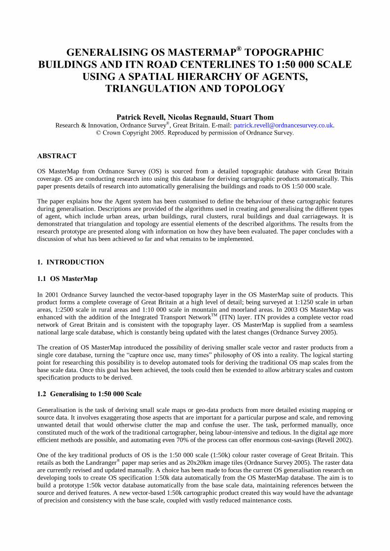
Figure 1. Flowline for the 1:50k generalisation prototype.
Figure 1 shows the prototype generalisation flowline, and the tasks between import and export for which the top level agent is responsible. The top level agent begins by delegating generalisation of the ITN road network to the road network agent, details of which are provided in section 3. The top level agent next identifies urban areas and rural building clusters, then further divides those settlements by the road network. These partitioning processes will be presented in section 4. Once the urban areas and rural building clusters have been identified, the top level agent delegates to urban area agents and rural building cluster agents for managing the difference types of problems found in these types of settlement. Details of the urban building generalisation can be found in section 5, while information on the rural building generalisation is provided in section 6. 3. ROAD NETWORK GENERALISATION The ITN road network traverses the entire map, it is difficult to break into independent sub-networks and has a low data volume compared to the topography layer. For these reasons it is most straightforward to generalise the road network in its entirety, without any initial partitioning. It is necessary to generalise the road network before any other feature classes, since it has a high level of interaction with the other features to be generalised, and later generalisation operations are very dependant on the roads being in their final position. The road network agent performs some basic tasks itself and delegates the more complex tasks to sub-agents. 3.1 Short Dead Ends Removing short dead ends from a topologically connected road network is a very simple generalisation operation. Each link is checked to see if it is a dead end, by testing both ends to see if they connect to the network. Dead ends shorter than the threshold value in the map specification are removed. This operation is performed by the road network agent. 3.2 Dual Carriageways The dual carriageway links in the road network can be selected using ITN attributes and the dual carriageways agent is assigned responsibility for generalising these links . Note that all of the dual carriageway links have a one-way direction attribute. 3.2.1 Detecting Twins : The first task is to identify the dual carriageway strokes, where a stroke represents the full extent of one side of a dual carriageway. It is not possible to use the ITN attribution for this task. After finding the starting link of a stroke, the next link is chosen by following the topology reference to the set of connecting links. The choice of �whether to step� and �to which link� is determined by �checking the rightmost link - if its one-way direction is forward, and its geometry is fairly straight ahead then step to this link, unless the junction is a stroke crossing stroke intersection�. This method of tracking has proved to identify strokes which can be correctly paired up in the next step. Once the data have been enhanced by identifying the strokes, these strokes are paired together according to the characteristics of their ends. They may have a coincident end point, or be attached through the road network, or be
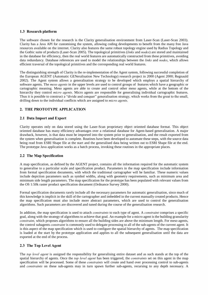
attached to another pair of strokes. Once the strokes have been paired, the responsibility for generalising any given pair of strokes is delegated to the stroke pair agent. The stroke pair agent is able to quickly reference the constituent links for a pair of strokes, and also store the type of end point connectivity for that pair. 3.2.2 Collapsing Twins : The stroke pair agent now must construct a centreline for the pair of strokes, such that the dual carriageway is represented by a single stroke in the generalised network. Collapsing a pair of lines into a centreline is commonly achieved using a skeleton algorithm. This step is assisted by the triangulation package developed at OS for use with Clarity (Regnauld 2005). A skeleton algorithm has been developed based on the triangulation, using similar principles as those described in (Ai and van Oosterom 2002) and this is applied to the pair of strokes. An example of the triangulation (in green) and the resulting centre line (in pink) is shown in Figure 2.
Figure 2. Collapsing pairs of strokes to single centrelines using triangulation.
Ordnance Survey © Crown Copyright. All rights reserved. Once the initial centreline has been calculated, the ends have to be tidied up. This involves extending and intersecting the new centreline to join with either an attached road section, or with a second merged centre line, depending on the type of paired end. 3.2.3 Reconnecting the Network : Once all the dual features have been satisfactorily collapsed, the stroke pair agents are activated to produce information about their connectivity with the surrounding road network. The two strokes from each agent are now removed from the network and the new centrelines are connected to rest of the network. The centrelines are structured so that there is a topological node at each new connection. This decomposes the centreline down into new links, which are assigned attributes from the closest of the original links. Using the new connectivity it is possible to generate a representation for the centrelines, depicting dual carriageways as a triple line symbol, as in the top right of Figure 3. Gaps in the central line can be used to convey the connectivity to one or both carriageways from any side roads. 3.3 Generating a Cartographic Representation The final operation performed by the road network agent is to transform the simplified network into road fill polygons, road casing lines and dead end lines. Modelling the cartographic representation of roads explicitly gives a result superior to applying a display style to the road network and makes interactive editing a very natural process. There is an efficiency advantage in calculating the representation only once, since whenever another feature needs to interact with the roads during generalisation, the representation can be quickly retrieved from the database. Buildings, forests and lakes often share their boundaries with the road casing, so these topological relationships can now be modelled explicitly. The algorithm begins by buffering all the Motorway links by the appropriate width in the map specification, then the buffers are combined in the database. Next the A Road links are processed in the same way, ensuring that the buffers do not overlap. The buffer size is doubled for any dual carriageway links. This is followed by the B Road and Minor Road links, terminating with the unclassified roads. This strategy ensures that the more important roads take priority in the depiction. The buffer polygons for each type of road are attributed for the type of road they represent, so they can be plotted with the appropriate coloured fill. During this processing, network dead ends are detected and the road fill polygons truncated to prevent curved dead ends. Line objects are created across each dead end.
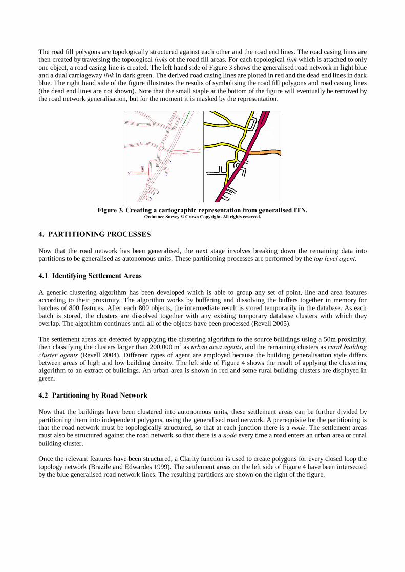
The road fill polygons are topologically structured against each other and the road end lines. The road casing lines are then created by traversing the topological links of the road fill areas. For each topological link which is attached to only one object, a road casing line is created. The left hand side of Figure 3 shows the generalised road network in light blue and a dual carriageway link in dark green. The derived road casing lines are plotted in red and the dead end lines in dark blue. The right hand side of the figure illustrates the results of symbolising the road fill polygons and road casing lines (the dead end lines are not shown). Note that the small staple at the bottom of the figure will eventually be removed by the road network generalisation, but for the moment it is masked by the representation.
Figure 3. Creating a cartographic representation from generalised ITN.
Ordnance Survey © Crown Copyright. All rights reserved. 4. PARTITIONING PROCESSES Now that the road network has been generalised, the next stage involves breaking down the remaining data into partitions to be generalised as autonomous units. These partitioning processes are performed by the top level agent. 4.1 Identifying Settlement Areas A generic clustering algorithm has been developed which is able to group any set of point, line and area features according to their proximity. The algorithm works by buffering and dissolving the buffers together in memory for batches of 800 features. After each 800 objects, the intermediate result is stored temporarily in the database. As each batch is stored, the clusters are dissolved together with any existing temporary database clusters with which they overlap. The algorithm continues until all of the objects have been processed (Revell 2005). The settlement areas are detected by applying the clustering algorithm to the source buildings using a 50m proximity, then classifying the clusters larger than 200,000 m2 as urban area agents, and the remaining clusters as rural building cluster agents (Revell 2004). Different types of agent are employed because the building generalisation style differs between areas of high and low building density. The left side of Figure 4 shows the result of applying the clustering algorithm to an extract of buildings. An urban area is shown in red and some rural building clusters are displayed in green. 4.2 Partitioning by Road Network Now that the buildings have been clustered into autonomous units, these settlement areas can be further divided by partitioning them into independent polygons, using the generalised road network. A prerequisite for the partitioning is that the road network must be topologically structured, so that at each junction there is a node. The settlement areas must also be structured against the road network so that there is a node every time a road enters an urban area or rural building cluster. Once the relevant features have been structured, a Clarity function is used to create polygons for every closed loop the topology network (Brazile and Edwardes 1999). The settlement areas on the left side of Figure 4 have been intersected by the blue generalised road network lines. The resulting partitions are shown on the right of the figure.
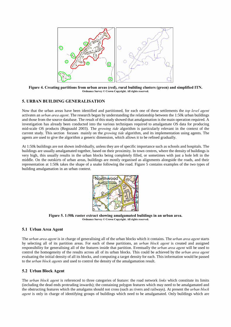
Figure 4. Creating partitions from urban areas (red), rural building clusters (green) and simplified ITN.
Ordnance Survey © Crown Copyright. All rights reserved.
5. URBAN BUILDING GENERALISATION Now that the urban areas have been identified and partitioned, for each one of these settlements the top level agent activates an urban area agent. The research began by understanding the relationship between the 1:50k urban buildings and those from the source database. The result of this study showed that amalgamation is the main operation required. A investigation has already been conducted into the various techniques required to amalgamate OS data for producing mid-scale OS products (Regnauld 2003). The growing tide algorithm is particularly relevant in the context of the current study. This section focuses mainly on the growing tide algorithm, and its implementation using agents. The agents are used to give the algorithm a generic dimension, which allows it to be refined gradually. At 1:50k buildings are not shown individually, unless they are of specific importance such as schools and hospitals. The buildings are usually amalgamated together, based on their proximity. In town centres, where the density of buildings is very high, this usually results in the urban blocks being completely filled, or sometimes with just a hole left in the middle. On the outskirts of urban areas, buildings are mostly organised as alignments alongside the roads, and their representation at 1:50k takes the shape of a snake following the road. Figure 5 contains examples of the two types of building amalgamation in an urban context.
Figure 5. 1:50k raster extract showing amalgamated buildings in an urban area.
Ordnance Survey © Crown Copyright. All rights reserved. 5.1 Urban Area Agent The urban area agent is in charge of generalising all of the urban blocks which it contains. The urban area agent starts by selecting all of its partition areas. For each of these partitions, an urban block agent is created and assigned responsibility for generalising all of the features inside that partition. Eventually the urban area agent will be used to control the homogeneity of the results across all of its urban blocks. This could be achieved by the urban area agent evaluating the initial density of all its blocks, and computing a target density for each. This information would be passed to the urban block agents and used to control the density of the amalgamation result. 5.2 Urban Block Agent The urban block agent is referenced to three categories of feature: the road network links which constitute its limits (including the dead ends protruding inwards); the containing polygon features which may need to be amalgamated and the obstructing features which the amalgams should not cross (such as rivers and railways). At present the urban block agent is only in charge of identifying groups of buildings which need to be amalgamated. Only buildings which are
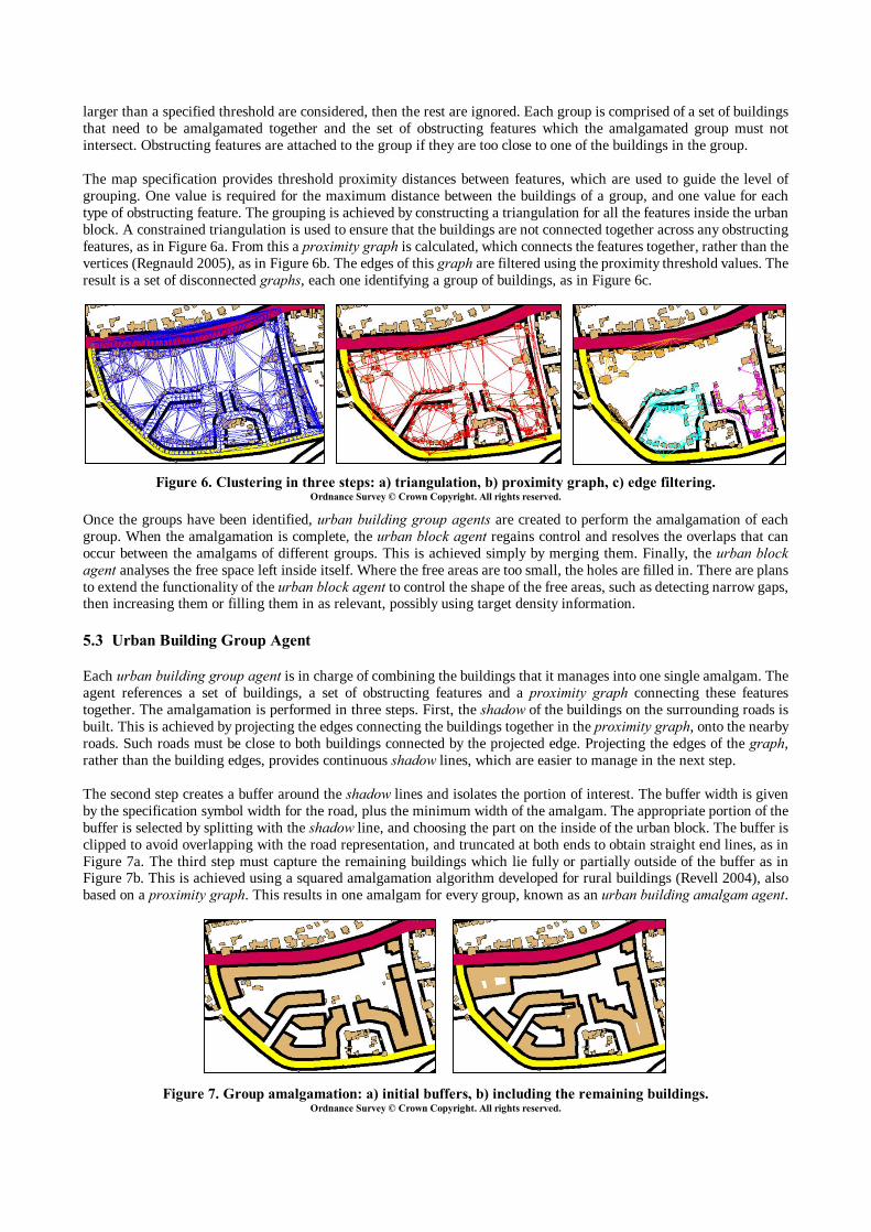
larger than a specified threshold are considered, then the rest are ignored. Each group is comprised of a set of buildings that need to be amalgamated together and the set of obstructing features which the amalgamated group must not intersect. Obstructing features are attached to the group if they are too close to one of the buildings in the group. The map specification provides threshold proximity distances between features, which are used to guide the level of grouping. One value is required for the maximum distance between the buildings of a group, and one value for each type of obstructing feature. The grouping is achieved by constructing a triangulation for all the features inside the urban block. A constrained triangulation is used to ensure that the buildings are not connected together across any obstructing features, as in Figure 6a. From this a proximity graph is calculated, which connects the features together, rather than the vertices (Regnauld 2005), as in Figure 6b. The edges of this graph are filtered using the proximity threshold values. The result is a set of disconnected graphs, each one identifying a group of buildings, as in Figure 6c.
Figure 6. Clustering in three steps: a) triangulation, b) proximity graph, c) edge filtering.
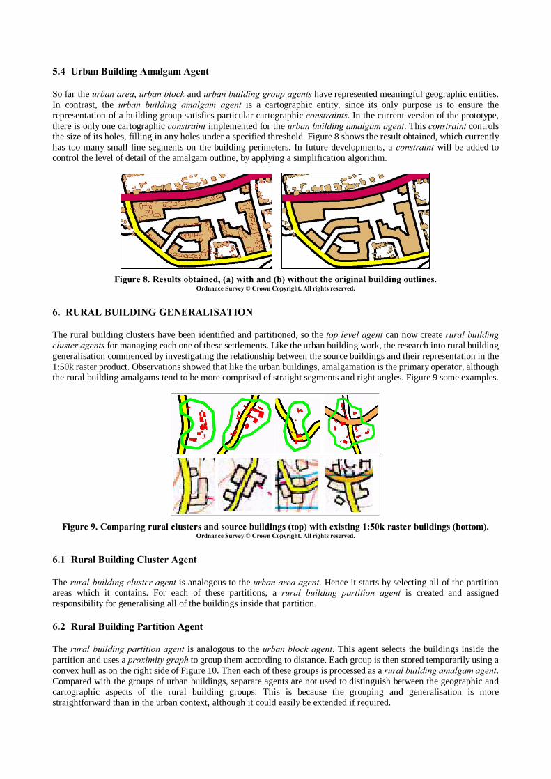
Ordnance Survey © Crown Copyright. All rights reserved. Once the groups have been identified, urban building group agents are created to perform the amalgamation of each group. When the amalgamation is complete, the urban block agent regains control and resolves the overlaps that can occur between the amalgams of different groups. This is achieved simply by merging them. Finally, the urban block agent analyses the free space left inside itself. Where the free areas are too small, the holes are filled in. There are plans to extend the functionality of the urban block agent to control the shape of the free areas, such as detecting narrow gaps, then increasing them or filling them in as relevant, possibly using target density information. 5.3 Urban Building Group Agent Each urban building group agent is in charge of combining the buildings that it manages into one single amalgam. The agent references a set of buildings, a set of obstructing features and a proximity graph connecting these features together. The amalgamation is performed in three steps. First, the shadow of the buildings on the surrounding roads is built. This is achieved by projecting the edges connecting the buildings together in the proximity graph, onto the nearby roads. Such roads must be close to both buildings connected by the projected edge. Projecting the edges of the graph, rather than the building edges, provides continuous shadow lines, which are easier to manage in the next step. The second step creates a buffer around the shadow lines and isolates the portion of interest. The buffer width is given by the specification symbol width for the road, plus the minimum width of the amalgam. The appropriate portion of the buffer is selected by splitting with the shadow line, and choosing the part on the inside of the urban block. The buffer is clipped to avoid overlapping with the road representation, and truncated at both ends to obtain straight end lines, as in Figure 7a. The third step must capture the remaining buildings which lie fully or partially outside of the buffer as in Figure 7b. This is achieved using a squared amalgamation algorithm developed for rural buildings (Revell 2004), also based on a proximity graph. This results in one amalgam for every group, known as an urban building amalgam agent.
Figure 7. Group amalgamation: a) initial buffers, b) including the remaining buildings. Ordnance Survey © Crown Copyright. All rights reserved.
a) b) c)
a) b)
5.4 Urban Building Amalgam Agent So far the urban area, urban block and urban building group agents have represented meaningful geographic entities. In contrast, the urban building amalgam agent is a cartographic entity, since its only purpose is to ensure the representation of a building group satisfies particular cartographic constraints. In the current version of the prototype, there is only one cartographic constraint implemented for the urban building amalgam agent. This constraint controls the size of its holes, filling in any holes under a specified threshold. Figure 8 shows the result obtained, which currently has too many small line segments on the building perimeters. In future developments, a constraint will be added to control the level of detail of the amalgam outline, by applying a simplification algorithm.
Figure 8. Results obtained, (a) with and (b) without the original building outlines.
Ordnance Survey © Crown Copyright. All rights reserved.
6. RURAL BUILDING GENERALISATION The rural building clusters have been identified and partitioned, so the top level agent can now create rural building cluster agents for managing each one of these settlements. Like the urban building work, the research into rural building generalisation commenced by investigating the relationship between the source buildings and their representation in the 1:50k raster product. Observations showed that like the urban buildings, amalgamation is the primary operator, although the rural building amalgams tend to be more comprised of straight segments and right angles. Figure 9 some examples.
Figure 9. Comparing rural clusters and source buildings (top) with existing 1:50k raster buildings (bottom).
Ordnance Survey © Crown Copyright. All rights reserved. 6.1 Rural Building Cluster Agent The rural building cluster agent is analogous to the urban area agent. Hence it starts by selecting all of the partition areas which it contains. For each of these partitions, a rural building partition agent is created and assigned responsibility for generalising all of the buildings inside that partition. 6.2 Rural Building Partition Agent The rural building partition agent is analogous to the urban block agent. This agent selects the buildings inside the partition and uses a proximity graph to group them according to distance. Each group is then stored temporarily using a convex hull as on the right side of Figure 10. Then each of these groups is processed as a rural building amalgam agent. Compared with the groups of urban buildings, separate agents are not used to distinguish between the geographic and cartographic aspects of the rural building groups. This is because the grouping and generalisation is more straightforward than in the urban context, although it could easily be extended if required.
a) b)
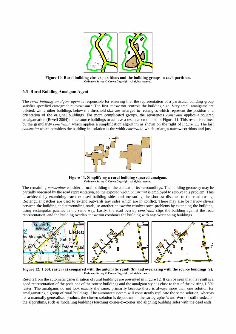
Figure 10. Rural building cluster partitions and the building groups in each partition.
Ordnance Survey © Crown Copyright. All rights reserved.
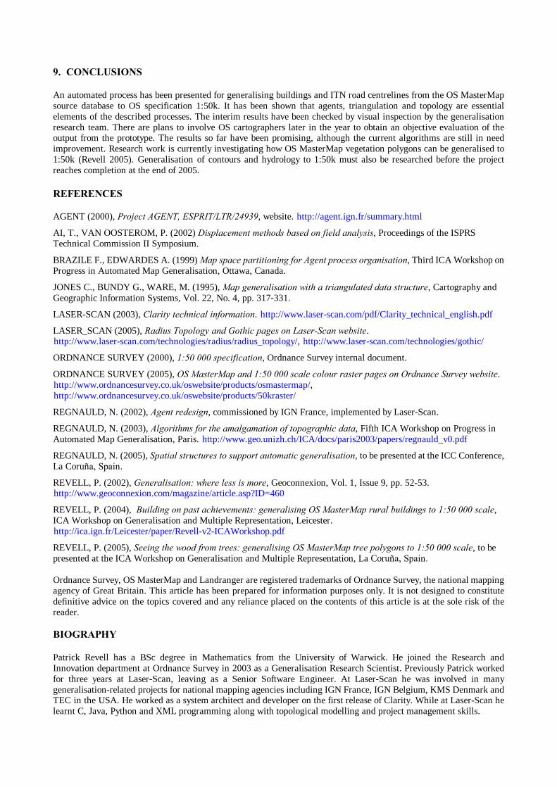
6.3 Rural Building Amalgam Agent The rural building amalgam agent is responsible for ensuring that the representation of a particular building group satisfies specified cartographic constraints. The first constraint controls the building size. Very small amalgams are deleted, while other buildings below the threshold size are enlarged to rectangles which represent the position and orientation of the original buildings. For more complicated groups, the squareness constraint applies a squared amalgamation (Revell 2004) to the source buildings to achieve a result as on the left of Figure 11. This result is refined by the granularity constraint, which applies a simplification algorithm as shown on the right of Figure 11. The last constraint which considers the building in isolation is the width constraint, which enlarges narrow corridors and juts.
Figure 11. Simplifying a rural building squared amalgam.
Ordnance Survey © Crown Copyright. All rights reserved. The remaining constraints consider a rural building in the context of its surroundings. The building geometry may be partially obscured by the road representation, so the exposed width constraint is employed to resolve this problem. This is achieved by examining each exposed building side, and measuring the shortest distance to the road casing. Rectangular patches are used to extend outwards any sides which are in conflict. There may also be narrow slivers between the building and surrounding roads, so another constraint resolves such problems by extending the building, using rectangular patches in the same way. Lastly, the road overlap constraint clips the building against the road representation, and the building overlap constraint combines the building with any overlapping buildings.
Figure 12. 1:50k raster (a) compared with the automatic result (b), and overlaying with the source buildings (c).
Ordnance Survey © Crown Copyright. All rights reserved. Results from the automatic generalisation of rural buildings are presented in Figure 12. It can be seen that the result is a good representation of the positions of the source buildings and the amalgam style is close to that of the existing 1:50k raster. The amalgams do not look exactly the same, primarily because there is always more than one solution for amalgamating a group of rural buildings. The automated system will consistently replicate the same solution, whereas for a manually generalised product, the chosen solution is dependant on the cartographer�s art. Work is still needed on the algorithms, such as modelling buildings touching corner-to-corner and aligning building sides with the dead ends.
a) c) b)
9. CONCLUSIONS An automated process has been presented for generalising buildings and ITN road centrelines from the OS MasterMap source database to OS specification 1:50k. It has been shown that agents, triangulation and topology are essential elements of the described processes. The interim results have been checked by visual inspection by the generalisation research team. There are plans to involve OS cartographers later in the year to obtain an objective evaluation of the output from the prototype. The results so far have been promising, although the current algorithms are still in need improvement. Research work is currently investigating how OS MasterMap vegetation polygons can be generalised to 1:50k (Revell 2005). Generalisation of contours and hydrology to 1:50k must also be researched before the project reaches completion at the end of 2005. REFERENCES AGENT (2000), Project AGENT, ESPRIT/LTR/24939, website. http://agent.ign.fr/summary.html
AI, T., VAN OOSTEROM, P. (2002) Displacement methods based on field analysis, Proceedings of the ISPRS Technical Commission II Symposium.
BRAZILE F., EDWARDES A. (1999) Map space partitioning for Agent process organisation, Third ICA Workshop on Progress in Automated Map Generalisation, Ottawa, Canada.
JONES C., BUNDY G., WARE, M. (1995), Map generalisation with a triangulated data structure, Cartography and Geographic Information Systems, Vol. 22, No. 4, pp. 317-331.
LASER-SCAN (2003), Clarity technical information. http://www.laser-scan.com/pdf/Clarity_technical_english.pdf
LASER_SCAN (2005), Radius Topology and Gothic pages on Laser-Scan website. http://www.laser-scan.com/technologies/radius/radius_topology/, http://www.laser-scan.com/technologies/gothic/
ORDNANCE SURVEY (2000), 1:50 000 specification, Ordnance Survey internal document.
ORDNANCE SURVEY (2005), OS MasterMap and 1:50 000 scale colour raster pages on Ordnance Survey website. http://www.ordnancesurvey.co.uk/oswebsite/products/osmastermap/, http://www.ordnancesurvey.co.uk/oswebsite/products/50kraster/
REGNAULD, N. (2002), Agent redesign, commissioned by IGN France, implemented by Laser-Scan.
REGNAULD, N. (2003), Algorithms for the amalgamation of topographic data, Fifth ICA Workshop on Progress in Automated Map Generalisation, Paris. http://www.geo.unizh.ch/ICA/docs/paris2003/papers/regnauld_v0.pdf
REGNAULD, N. (2005), Spatial structures to support automatic generalisation, to be presented at the ICC Conference, La Coruña, Spain.
REVELL, P. (2002), Generalisation: where less is more, Geoconnexion, Vol. 1, Issue 9, pp. 52-53. http://www.geoconnexion.com/magazine/article.asp?ID=460
REVELL, P. (2004), Building on past achievements: generalising OS MasterMap rural buildings to 1:50 000 scale, ICA Workshop on Generalisation and Multiple Representation, Leicester. http://ica.ign.fr/Leicester/paper/Revell-v2-ICAWorkshop.pdf
REVELL, P. (2005), Seeing the wood from trees: generalising OS MasterMap tree polygons to 1:50 000 scale, to be presented at the ICA Workshop on Generalisation and Multiple Representation, La Coruña, Spain. Ordnance Survey, OS MasterMap and Landranger are registered trademarks of Ordnance Survey, the national mapping agency of Great Britain. This article has been prepared for information purposes only. It is not designed to constitute definitive advice on the topics covered and any reliance placed on the contents of this article is at the sole risk of the reader. BIOGRAPHY Patrick Revell has a BSc degree in Mathematics from the University of Warwick. He joined the Research and Innovation department at Ordnance Survey in 2003 as a Generalisation Research Scientist. Previously Patrick worked for three years at Laser-Scan, leaving as a Senior Software Engineer. At Laser-Scan he was involved in many generalisation-related projects for national mapping agencies including IGN France, IGN Belgium, KMS Denmark and TEC in the USA. He worked as a system architect and developer on the first release of Clarity. While at Laser-Scan he learnt C, Java, Python and XML programming along with topological modelling and project management skills.