Embed Size (px)
Citation preview

Generalised nonlinear theory for one-portmicrowave active circuits
N.A. MansourW.R. Tinga
Indexing term: Microwave circuits and networks
Abstract: A nonlinear model characterising two-terminal microwave active circuits under dynamicand steady-state conditions is developed from ageneralised circuit approach. The model considersthe active circuit as a black box consisting of aone-port passive circuit and a one-port activedevice. The response of the active and passive cir-cuits to modulated time-dependent signals withslowly varying amplitude and phase is derived.The model takes into consideration the nonlineardependence of the active-device currents on RFvoltage amplitude and frequency; also it considersthe effects of nonlinearities of the passive circuiton frequency. This makes the model suitable forapplications which employ strongly modulatedsignals for which Van der Pol's cubic nonlinearitymodel fails.
1 Introduction
Microwave active circuits using solid-state active devicessuch as Impatt and Gunn diodes have established them-selves in the fields of generation [1, 2], amplification[3-11] and detection [12-17] of a frequency modulated(FM) or phase modulated (PM) signal. These deviceshave since been incorporated into power-combiningschemes [18-23] to achieve maximum power especiallyin the millimeter frequency bands.
Despite the fact that different physical phenomena areemployed (e.g. a combination of transit-time effects witheither the electron transfer or avalanche generation),there is a complete similarity from the circuit point ofview: all these active devices are two-terminal elementspresenting negative conductance to the external circuitry.
To optimise efficiency and economy, which are keyfigures of merit in power applications, these devices arestrongly driven into their nonlinear region. Consequentlyany detailed characterisation of the dynamic behaviour ofactive circuits, which is of primary importance to the de-signers, is very complex and requires extensive numericalcalculations. Moreover, information obtained fromdynamic studies on active circuits is even vital for design-ing circuits used in digital communication systems.
Paper 5515H (E12), received 17th May 1985Prof. Mansour is with Coal Research Laboratories, Energy, Mines andResources, PO Bag 1280, Devon, Alberta, Canada TOC 1EOProf. Tinga is, and Prof. Mansour is Adjunct Professor, with the Elec-trical Engineering Department, University of Alberta, Edmonton,Canada, T6G 2G7
Microwave active solid-state devices are usually verysmall compared with the guided wavelength so that theelectric and magnetic fields do not vary significantlyalong their dimensions. Therefore, conventional circuittheory can be used in the analysis of these devices evenup to the millimeter wavelength range. The deviceresponse to a single-frequency excitation, which may beeither RF voltage or current depending on the embed-ding circuitry, contains an appreciable number of harmo-nics, the amplitudes of which depend on the signalstrength. The higher harmonics, however, are greatlyattenuated by tuning the high-Q embedding circuitry tothe fundamental frequency. This enables the active deviceto be uniquely characterised at the signal frequency by anonlinear immittance dependent on the signal amplitudeand frequency. Consequently, equivalent-circuit represen-tation can be employed when investigating the active-circuit response to unmodulated carrier wave (CW)signals. The steady-state amplitude and phase of thedevice response at the signal frequency can be obtainedby solving nonlinear algebraic circuit equations.However, in many applications, some additional informa-tion is vital, e.g. stability and noise properties of thesteady-state solution, response of the active circuit tomodulated signals (in particular nonlinear and phase dis-tortion and amplitude modulation (AM) to PMconversion) and intermodulation characteristics of thedevice. This information cannot be obtained from exist-ing theories.
The oldest method for dynamic studies on one-portdevices is that developed by Van der Pol [24] fornegative-conductance oscillators. He approximated thecurrent response of the device i by
i = —<xv + yv* (1)
where v is the applied voltage and a, y are positive con-stants characterising the given device. Representing theembedding circuitry by a single tuned parallel resonantcircuit, Van der Pol arrived at a second-order nonlineardifferential equation for which a solution is sought in theform
v(t) = A(t) sin \_(bt (2)
Thus, the rapid time variation of v(t) is assumed to beharmonic (cb), and the slow variations of v(t) aredescribed by the unknown functions A(i) and 0(t) whichsatisfy the relationships
dA/dt <£ cbA d<j>/dt <$ cb (3)
There are a few serious shortcomings when applying Vander Pol's approach to active solid-state devices. First,solid-state devices are characterised by nonlinear conduc-tance as well as susceptance; Kuno [25] has extended
IEE PROCEEDINGS, Vol. 134, Pt. H, No. 5, OCTOBER 1987 411
this approach by including nonlinear inductance. Sec-ondly, because of the single tuned circuit representationof the embedding circuitry, the active solid-state micro-wave circuit, which usually operates in a wide frequencyband, cannot be well described. Finally, the active deviceis described by means of various constants, e.g. y, whichare rather general and cannot be accurately determinedfor a given device.
Many present dynamic studies are based on anapproach developed by Kurokawa [26] in 1969 for noiseand stability investigations on CW oscillators. Kurokawaexpresses the diode voltage and current in the form
v(t) = A(t) Re {expj[<bt + 0(0]}
He does not restrict the passive circuitry to a single tunedmodel. Instead, he uses a generalised admittance expres-sion in which the co-factor is replaced by the operator
COdt J dt
and the active device is represented by its large-signalimmittance. Expanding the immittance expressionaround a>, Kurokawa derives two first-order differentialequations for <f)(t) and A(t). Since the coefficients in theseequations are related to the device immittance, thisapproach can describe a particular device accurately. Thegreat potential of this approach lies in the study ofsteady-state CW operation and small noise disturbances.However, since the device nonlinearities are not fullytaken into account, this method is hardly suitable for thestudy of active devices exposed to strongly modulated ortransient signals.
In 1972, another approach was proposed by Gustafs-son, Hansson and Lundstrom [27]. Representing theactive circuit by a feedback model containing a nonlinearelement, they were able to apply a describing-functiontechnique. When dealing with strongly modulatedsignals, this technique is only slightly better than Kuro-kawa's approach. In the last few years little has beennoted in the literature in regard to nonlinear modelling oftwo-terminal microwave active circuits.
In the following Sections, a more general technique forthe characterisation of nonlinear microwave active cir-cuits will be developed- In this approach, the active andpassive parts of the microwave active circuit will be con-sidered as a black box (more general than that consideredby Kuno and the aforementioned techniques). This modelalso takes into consideration the effect of nonlinearities ofthe circuit on RF amplitude and on frequency up to anydesired order.
2 General circuit approach
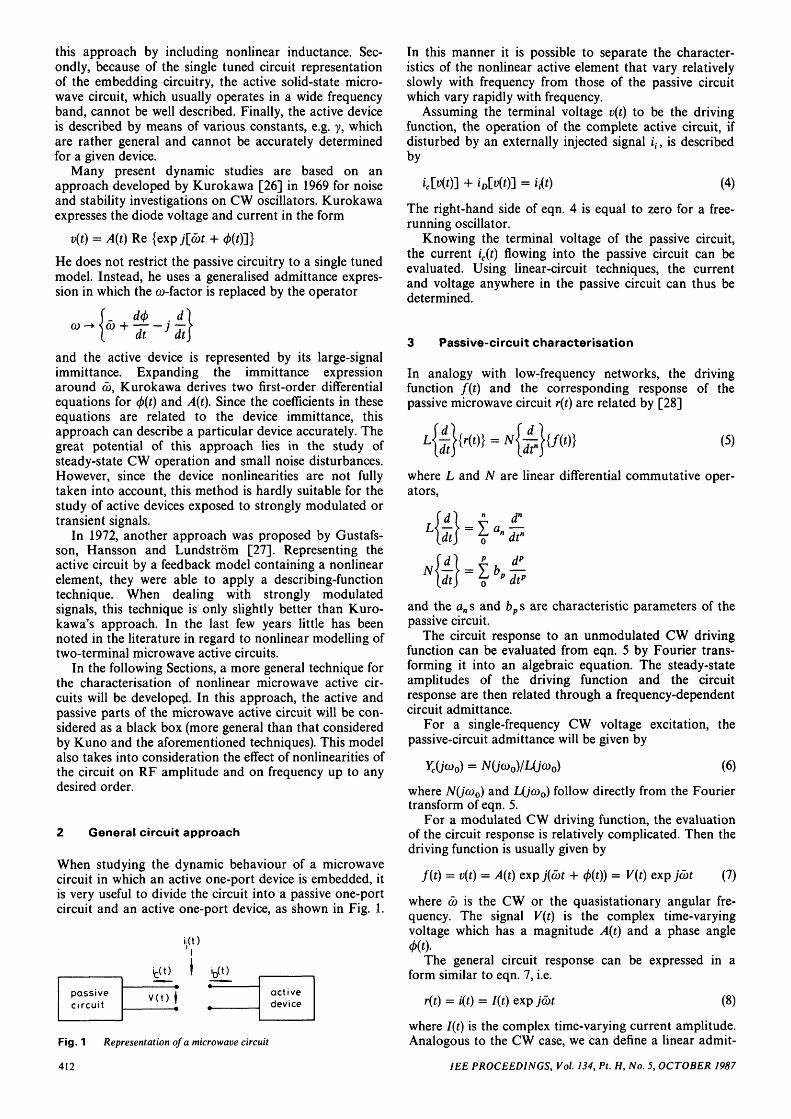
When studying the dynamic behaviour of a microwavecircuit in which an active one-port device is embedded, itis very useful to divide the circuit into a passive one-portcircuit and an active one-port device, as shown in Fig. 1.
iD(t)
passivecircuit
tft)V ( t ) f active
device
In this manner it is possible to separate the character-istics of the nonlinear active element that vary relativelyslowly with frequency from those of the passive circuitwhich vary rapidly with frequency.
Assuming the terminal voltage v(t) to be the drivingfunction, the operation of the complete active circuit, ifdisturbed by an externally injected signal it, is describedby
'cMO] + iflEKO] = *'i(0 (4)
The right-hand side of eqn. 4 is equal to zero for a free-running oscillator.
Knowing the terminal voltage of the passive circuit,the current ic(t) flowing into the passive circuit can beevaluated. Using linear-circuit techniques, the currentand voltage anywhere in the passive circuit can thus bedetermined.
3 Passive-circuit characterisation
In analogy with low-frequency networks, the drivingfunction f(t) and the corresponding response of thepassive microwave circuit r(t) are related by [28]
(5)
where L and N are linear differential commutative oper-ators,
d"
and the an s and bp s are characteristic parameters of thepassive circuit.
The circuit response to an unmodulated CW drivingfunction can be evaluated from eqn. 5 by Fourier trans-forming it into an algebraic equation. The steady-stateamplitudes of the driving function and the circuitresponse are then related through a frequency-dependentcircuit admittance.
For a single-frequency CW voltage excitation, thepassive-circuit admittance will be given by
o) = N(jco0)/L(jco0) (6)
where N(jco0) and L(jco0) follow directly from the Fouriertransform of eqn. 5.
For a modulated CW driving function, the evaluationof the circuit response is relatively complicated. Then thedriving function is usually given by
f(t) = v(t) = A(t) exp j(cot + </>(0) = V(t) exp jcbt (7)
where cb is the CW or the quasistationary angular fre-quency. The signal V(t) is the complex time-varyingvoltage which has a magnitude A(t) and a phase angle
The general circuit response can be expressed in aform similar to eqn. 7, i.e.
r(t) = i(t) = I(t) exp jcot (8)
Fig. 1 Representation of a microwave circuit
412
where I(t) is the complex time-varying current amplitude.Analogous to the CW case, we can define a linear admit-
1EE PROCEEDINGS, Vol. 134, Pt. H, No. 5, OCTOBER 1987
tance operator Yc\jco(t)~] for the nonCW case by
The complex amplitude of the current response is thengiven by
I(t)=Yc[jco(ty\{A(t)expj<t>(t)} (10)
The frequency operator can be defined by
(11)
where co(t) is the instantaneous frequency which for v(t)will be
co(t) = cb +dt
(12)
In many microwave applications, the amplitude A(t) andphase <j){t) usually change insignificantly within one RFperiod, i.e.
dA/dt ^ cbA dcf>/dt <̂ cb (13)
Accordingly, the admittance operator can be expandedinto a Taylor series about co and then I(t) will be given by
= | px {A(t) exp jcf>(t)} (14)
Eqn. 14 is known as the Carson-Fry series [28]. The con-vergence of this series was discussed by Stumpers [28] forFM signals. Stumpers pointed out that any terminatedseries used to approximate eqn. 14 must be discussedtogether with the remainder since the complete seriesmay not be convergent for frequencies far removed fromcb.
Rewriting eqn. 14 by separating the real and imagin-ary parts of Yc[Jco(ty], the current amplitude will be givenby
cb2) nS(co2)]
d(co2r J
n!{A(t)expjm}
where
[ty\ = G[co2{ty] ±jco(t)S[co2(t)']
G[co2{t)~\ and S[co2(t)] are conductance and capacitive(positive sign) or inductive (negative sign) susceptanceoperators, respectively. The convergence restrictionapplying to eqn. 14 also holds for eqn. 15. Since the fre-quency deviation (normally a few per cent) at microwavefrequencies is usually within the series convergence inter-val, a finite number of terms will approximate the currentamplitude with the desired accuracy for practical pur-poses.
4 Active-circuit model
The relation between the terminal voltage and thecurrent response of a nonlinear active circuit can beobtained from eqn. 5 by allowing the coefficients a0, . . . ,
1EE PROCEEDINGS, Vol. 134, Pt. H, No. 5, OCTOBER 1987
an and b0, . . . , bp to depend on the driving function.Expressing this dependence as a power series, eqn. 5becomes
at J
(.6)
where amh and bph are constants depending both on thenature of the embedding circuitry and the active device.For H — 0, the above equation simplifies to the relationdescribing passive circuits (eqn. 5), and for M = 0, P = 0and Amh = 0 for h > 0, the above relation is reduced to ageneralised Van der Pol equation for active devices. Fornonzero M, P and H, the current response of the activecircuit is generally a nonlinear function of the drivingfunction as well as its derivatives and its integrals. Eqn.16 describes the dynamics of RF active circuits on theassumption that the signal modulation has hardly anyeffect on the bias conditions.
In many applications (negative-conductance amplifiersand oscillators), single-carrier-frequency operation (as tothe power and energy flow) is the desired operationalmode. In practice, however, the terminal voltage is com-posed of a number of harmonic frequency components.Their amplitudes depend on the amplitude of the corre-sponding components of the nonlinear-device currentresponse and the impedance of the embedding circuitryat the particular harmonic frequency. Very often thedevice capacitance acts as a lowpass filter, drasticallyreducing the higher-harmonic voltage components at thedevice terminals. Then the single-carrier driving function,
w (17)
approximates the operating conditions of many activedevices very well. The quantities A(t) and (f)(t) are slowlyvarying functions of time, obeying the restrictions givenby eqn. 3; and no other restriction is imposed on thesefunctions. Thus a large variety of signals are described byeqn. 17, e.g. frequency- and amplitude-modulated signals,single- or multiple-frequency modulation, transientsignals and two or more signals with closely spacedcarrier frequencies.
In theoretical studies of active microwave circuits,single-frequency excitation, which considerably simplifiesthe mathematical treatment, is usually assumed. Onlyone exponential term of eqn. 17 (the one used in thepassive circuits) is considered in almost all studies. Innoise and stability investigations, this does not introduceany significant error. However, to properly describe thenonlinear operation of the active device with stronglymodulated signals, both the exponential terms have to beconsidered. No harmonic restrictions are imposed on thecircuit response, which is expressed in the form
(18)
-F
Here £ /*o denotes the summation of all terms with theexception of the bias term, and the complex amplitudewhich satisfies
= I*f(t) (19)
carries information on both the amplitude and the phaseof a particular current component.
413
The summation in vh from eqn. 16 is expanded usingeqn. 17, and if like terms are collected the summation invh can be written as
H H/2 H/2
HA*tty)]= Z Z «„. 2K 29A2\t)
h = 0 g=-H/2 h = \g\
x exp j2g[a>t + 0(0](H-D/2 (H-D/2
+ L, 2J a
g= - (H-D/2 h = \g\
x A2h+l(t) exp [j(2g + 1) • (d* + 0(0)]
(20)
Similarly, differentiating eqn. 18 'm' times and eqn. 17 'p'times yields
(21)
- F
and
= Es = - l .
(22)
In eqn. 20, the summations are carried out to the highestintegral number H/2 or (H — l)/2 and the coefficientsam,h,g
w i t n different gs are related to the coefficients amh
of eqn. 16.Substituting eqns. 20-22 into eqn. 16 yields
[ f H/2 H/2Z Z Z E K 2 u 9 m
/ *0 m = 0 l_0=-H/2 h = \g\
(H-l)/2 (H-D/2(am, 2h+l,2g+l A2h+i(t))
8= - (H -D/2 h = \g\
x (exp;[(2a +f+l)(bt + (2a
ifa + 4
[ T H/2I I E
s = - l . l p = 0 U = -
H/2 H/212h(
= -H/2 ft = |fll
s)a* + 2a0(O](H-D/2 (H-D/2
E E <g= - (H-D/2 h = |g|
x exp;[(2^ + s + + (2̂ +
(23)
The above set of nonlinear differential equations forcomplex current amplitudes describes the active-deviceresponse to a single-carrier driving function with noncon-stant amplitude. Even if all the parameters 'a' and '6'were known, the complexity of the above descriptionwould make it unsuitable for any numerical study. Thedescription of the active-device response becomes simplerif all passive circuit elements between the device terminalsand the active-device itself, namely all device packageparasitics, very often involving energy storage elements,
are included in the external passive circuitry. The trans-formation of the nonlinear-device quantities into the ter-minal quantities is then eliminated. Furthermore, sincethe external circuitry is assumed to present an infiniteadmittance at the device terminals at all frequencies otherthan the fundamental frequency, the current of this sim-plified active circuit does not contribute to higher-harmonic generation. Thus
am,H,g = 0 f o r | 0 | > O , | / i | > 0 (24)
and the equation set 23 is reduced to a set of uncoupleddifferential equations with constant coefficients. Thuseqn. 23 is reduced to
r M
Z Z am,0,L/?tO m = 0
of expi/a>r( jfcb +
[ 1 I" P ( H/2 H/2Z E ( I Is = - l l_p = O \g=-H\2 h = \g\
x (exp;[(20 + s)cbt
(H-D/2 (H-D/2
Z Zg= - (H-D/2 h = \g\
x (expj[{2g + s + l)cbt + (2g
e x p j s m
s)>>]
( 2 5 )
If, in the above equation, one considers the currentamplitudes of odd and even harmonics separately, for theodd order one gets
' 2 / + 1
[ P TH/2Z Z
p = 0 \_h = f
{ 2frp.2* + 2.2/+2^ (0exp;(2/ +
dry [ 2(26a)
and the corresponding expression for the even order is ofthe form
Ur =
{ P /(H-D/2
Z Z bP,2h-l,2f-lp=0 \ h=f
xA2h~\i) exp 0(2/- 1)0(0}
{ 2 e x p 7 ' W 1)0(0)
X | -JCO + —at
exp ~ (266)
where am> 0> 0 = am, bp< ht g = 0 for h > H a n d / > 0 in eqn.26a a n d / > 0 in eqn. 26b.
414 IEE PROCEEDINGS, Vol. 134, Pt. H, No. 5, OCTOBER 1987

Eqns. 26 can be regarded as generalised admittancerelations describing the current response of an activedevice to a single-carrier driving function with noncon-stant amplitude. The amplitudes of the current responseare nonlinear functions of the applied-voltage amplitude,its derivatives and integrals.
Knowing both sets of coefficients, i.e. a and b, thecurrent response of the active device could be evaluatedfor any amplitude and frequency of the driving function.Disregarding the fact that it may be very difficult to findthe appropriate sets of coefficients, the above descriptionof the active-device response is still extremely complex. Itwould lead to integrodifferential equations and is hardlyuseful for numerical studies.
Fortunately, the active-device description can be sig-nificantly simplified by the following choice of the a coef-ficients and still preserving the nonlinear dependence ofthe current on voltage amplitude and frequency,
= 0 for m > 0 (27)a0 = 1 a
Then, the square-bracketed [ ] differential operator ineqn. 26 is reduced to unity and the components of thecurrent response are given by
'2/+1
p H/2 r
= I I UP>2h>P=O h=f L 2 /
^2"(r)(exp;2/</)(t))
,2f+2A2h+2(t)(expj(2f +
d^p
( 2 8 a )
p (H-D/2
A/ LaP=O h=f
12/ i - l (0
x(exp;(2/-l)0(O)hd) + -
x (ex
A(t)(28b)
In this simpler description, the current response of anactive device is a nonlinear function of the voltage ampli-tude and its derivatives. Thus, a given set of b parameterswill accurately describe the device response in a more orless limited frequency range at large amplitudes of theapplied voltage. Using numerical methods based on thebicubic spline approximation [29], both the b-parameterevaluation and the current-response description for anyamplitude and frequency of the driving function can beaccomplished in a piece-wise manner.
5 Conclusions
In conclusion, we have derived two equations for thecurrent response of microwave passive and active circuits(eqns. 15 and 28) from basic circuit theory. In the deriva-tion of these responses, the nonlinearities of the activecircuit with RF voltage and frequency, and of the passivecircuit with frequency, are considered. These nonlin-earities are evident from the behaviour of the calculated
Impatt large-signal admittance reported by Gummel andScharfetter [30] and from the experimentally evaluateddata reported earlier [31]. The current responses togetherwith the RF current of the injected signal (substitutingeqns. 15 and 28 into eqn. 4) give the fundamental equa-tions representing the dynamic behaviour of a two-terminal microwave active circuit. This technique resultsin differential equations nonlinear in both frequency andRF amplitude. These equations have the advantage ofbeing able to characterise highly nonlinear active devices,e.g. Impatt diodes, which cannot be characterised by thesimplified cubic model of Van der Pol.
In the following paper in this issue (Nonlinear model-ling applied to one-port microwave active circuits [32]),the formulas derived here are used for the calculation ofthe dynamic behaviour of an Impatt-diode oscillator. Theactive- and passive-circuit parameters are determined byfitting device large-signal admittance data and the corre-sponding passive-circuit admittance data with bicubicand cubic splines, respectively. A technique for the solu-tion of nonlinear differential equations, which is difficultto obtain using an initial-value approach, is also present-ed and used to evaluate the transient response of anImpatt-diode oscillator.
6 References
1 SO, B.S., and GOUD, P.A.: 'Injection phase-locking properties ofbias-modulated IMPATT diode oscillators'. 8th International Con-ference Proceedings on Microwave and optical generation andamplification MOGA 70, Amsterdam, Netherlands, Sept. 1970
2 MARTIN, B., and HOBSON, G.S.: 'Angle modulation offrequency-locked Gunn oscillators', Electron. Lett., 1971, 7, (14), pp.399-401
3 JUDD, S.V.: 'Simple repeater for frequency-modulated signals usingtransferred-electron oscillators', ibid., 1968, 4, (2), p. 33
4 MASTALLI, P., RANDI, S., and VANNUCCHI, G.: 'A new micro-wave repeater for FM radio links', Alta Freq., 1968, 37, pp. 415-425
5 ISOBE, T., and TOKIDA, M.: 'Noise loading performance of aphase-locked IMPATT oscillator for multichannel FM signals',Proc. IEEE {Lett.), 1968, 56, pp. 873-875
6 ISOBE, T., and TOKIDA, M.: 'A new microwave amplifier formultichannel FM signals using a synchronized oscillator', IEEE J.Solid-State Circuits, 1969, SC-4, pp. 400-408
7 ISOBE, T., and TOKIDA, M.: 'Power amplification for FM andPM signals with synchronized IMPATT oscillators', IEEE Trans.,1970, MTT-18, pp. 906-911
8 KOHIYAMA, K., and MONMA, K.: 'A new type of all solid-state11 GHz band FM transmitter combining a Gunn diode and anIMPATT diode', Proc. IEEE {Lett.), 1969, 57, pp. 1232-1233
9 FLERI, D.A., and SOCCI, R.J.: 'Amplifying properties of Gunnoscillator in injection locked mode', ibid., 1969, 57, pp. 1205-1206
10 MARAZZI, E., and BELLARDO, A.: 'Thin-film injection-lockedoscillators and negative-resistance amplifiers for 2-GHz radio repea-ter', IEEE J. Solid-State Circuits, 1972, SC-7, pp. 23-32
11 TAKAYAMA, Y.: 'Power amplifier with IMPATT diodes in stableand injection-locked modes', IEEE Trans., 1972, MTT-20, pp.266-272
12 WOOD YARD, J.R.: 'Application of the autosynchronised oscillatorto frequency demodulation', Proc. Inst. Radio Eng., 1937, 25, pp.612-619
13 RUTHROFF, C.L.: 'Injection-locked-oscillator FM receiveranalysis', Bell Syst. Tech. J., 1968,47, pp. 1653-1661
14 OSBORNE, T.L., and ELMENDORF IV, C.H.: injection-lockedavalanche diode oscillator FM receiver', Proc. IEEE {Lett.), 1969,57, pp. 214-215
15 PRONI, E.: 'FM demodulator employing an injection-locked oscil-lator', Alta. Freq., 1969, 38, pp. 95-103
16 MURAKAMI, K.: 'A new phase-locked demodulator with injectionlocking', Electron. & Commun. Jpn., 1969, 52, pp. 119-120
17 HOBSON, G.S., and THOMAS, M.: 'Direct frequency demodu-lation with frequency-locked Gunn oscillators', Electron. Lett., 1971,7, (3), pp. 67-68
18 YEN, H.-C, and CHANG, K.: 'A 63-W W-band injection-lockedpulsed solid-state transmitter', IEEE Trans., 1981, MTT-29, pp.1292-1297
IEE PROCEEDINGS, Vol. 134, Pt. H, No. 5, OCTOBER 1987 415

19 CHANGE, K, THROWER, W.F., and HAYASHIBARA, G.M.:'Millimeter wave silicon IMPATT sources and combiners for the110-260GHz range', ibid., 1981, MTT-29, pp. 1278-1284
20 POTOCZNIAK, J.J., JACOBS, H., LOCASIO, C M , and G.NOVICK.: 'Power combiner with Gunn diode oscillators', ibid.,1982, MTT-30, pp. 724-728
21 MADIHIAN, M , and MIZUSHINE, S.: 'Combining the powersfrom multiple-device oscillators', ibid., 1982, MTT-30, pp. 1228-1233
22 THOREN, G.R., and VIROSTKO, M.J.: 'A high-power W-band(90-99 GHz) solid-state transmitter for high duty cycles and wideband width', ibid., 1983, MTT-31, pp. 183-188
23 MOONEY, D.W, and BAYUK, F.J.: 'Injection locking per-formance of a 41-GHz 10-W power combining amplifier', ibid., 1983,MTT-31, pp. 171-176
24 VAN DER POL, B.: 'Forced oscillations in a circuit with nonlinearresistance (Reception with reactive triode)', Philos. Mag., 1927, 3, pp.65-80
25 KUNO, H.J.: 'Analysis of nonlinear characteristics and transientresponse of IMPATT amplifiers', IEEE Trans., 1973, MTT-21, pp.694-702
26 KUROKAWA, K.: 'Some basic characteristics of broad band nega-tive resistance oscillator circuits', Bell Syst. Tech. J., 1969, 48, pp.1937-1955
27 GUSTAFSSON, L, HANSSON, G.M.B, and LUNDSTROM,K..J.: 'On the use of describing functions in the study of nonlinearactive circuits', IEEE Trans., 1972, MTT-20, pp. 402-409
28 STUMPERS, F.L.M.M.: 'Distortion IF frequency modulatedsignals in electrical networks', Commun. News, 1948, 9, pp. 82-92
29 AHLBERG, J.H, NELSON, E.N, and WALSH, J.L.: 'The theoryof splines and their applications' (Academic Press, New York, 1967)
30 SCHARFETTER, D.L., and GUMMEL, H.K.: 'Large-signalanalysis of silicon read-diode oscillator', IEEE Trans., 1969, ED-16,pp. 64-77
31 MANSOUR, N.A.: 'Nonlinear analysis of two terminal microwaveactive circuits'. PhD Thesis, Department of Electrical Engineering,University of Alberta, Edmonton, Canada, 1977
32 MANSOUR, N.A, and TINGA, W.R.: 'Nonlinear modellingapplied to one-port microwave active circuits', IEE Proc. H, Micro-waves, Antenna & Propag., 1987,134, (5), pp. 417-422
416IEE PROCEEDINGS, Vol. 134, Pt. H, No. 5, OCTOBER 1987


![A generalised approach to the propagation of uncertainty ...A generalised approach to the propagation of uncertainty in complex S-parameter measurements ... microwave source [6, 7]](https://img.pdfslide.us/doc/110x75/5e6e04de7e4bac30cc18b225/a-generalised-approach-to-the-propagation-of-uncertainty-a-generalised-approach.jpg)