Embed Size (px)
Citation preview
�
�������������������������� �������������������������������������������������������
�������������������������������������
���������������������������������������������
������ �� ��� ���� ����� ��������� ����� �������� ���� ��� � ��� ���� ��������
���������������� �������������������������������������������������
�������������������������������������������������
����������������� ��
�
�
�
�
������������ ���
a publisher's https://oatao.univ-toulouse.fr/28158
Joksimovi , Aleksandra and Carbonneau, Xavier and Crabé, Charline and Benichou, Emmanuel Generalised
Methodology for Sizing of Air Vehicles with Hybrid-Electric Propulsion. (2019) In: NATO AVT-RSY-323 Research
Symposium on Hybrid/Electric Aero-Propulsion Systems for Military Applications, 7 October 2019 - 9 October 2019
(Trondheim, Norway).
C2 - Restricted
STO-MP-AVT-323 PAPER NBR 13 - 1
NATO UNCLASSIFIED
Generalised Methodology for Sizing of Air Vehicles with Hybrid-Electric
Propulsion
Aleksandar Joksimović Institut Supérieur de l'Aéronautique et de l'Espace (ISAE-SUPAERO), Université de Toulouse,
31055 TOULOUSE Cedex 4
SERBIA
Xavier Carbonneau, Charline Crabé, Emmanuel Benichou Institut Supérieur de l'Aéronautique et de l'Espace (ISAE-SUPAERO), Université de Toulouse,
31055 TOULOUSE Cedex 4
FRANCE
[email protected], [email protected],
[email protected], [email protected]
Keywords: Hybrid/Electric Propulsion Systems Architectures, Aircraft Preliminary Sizing
ABSTRACT
In the context of increasing attention given to aircraft propulsive system electrification by the aeronautical
community, Department of Aerodynamics, Energetics and Propulsion at ISAE-SUPAERO is undertaking an
effort to develop a preliminary sizing tool for aeroplanes with propulsive architectures ranging between
conventional gas turbine and different hybrid-electric solutions. The baseline used to initiate this work is
semi-empirical handbook sizing method by Jan Roskam. The method is firstly extended by introducing a
generic propulsive power architecture space, described parametrically by an array of power hybridisation
parameters. Furthermore, a proposal of modified Breguet range equation is given for fuel weight iterations
including batteries. With these upgrades, a trial sizing run was performed on a Pilatus PC-12 test case to
verify the functioning of the developed tool. A more comprehensive study of an equivalent aeroplane
powered with various hybrid-electric solutions is then presented, along with an associated parametric study.
Mission performance results of all the hybrid architectures are inferior to the ones for the fuel-based
baseline, with the most promising solutions indicated by the results being series and parallel hybrid
architectures. While the tool produces qualitatively coherent results, the quantitative validity thereof is yet to
be ascertained. Notably, the hybrid range equation needs to be further placed under scrutiny and its
applicability for mission sizing of all the hybrid architectures of interest is to be validated. In the long run,
the work will look into other current limitations such as lack of possibility to consider battery recharge in the
mission calculations or lack of capability to perform sensitivity studies.
1.0 INTRODUCTION
1.1 Context
Rise in interest of the aeronautical community for aircraft electrification is observed by the day. The
phenomenon can be broken down into two major axes: electrification of nonpropulsive systems (e.g.
environmental control system (Sinnett, 2007)), or electrification of the propulsive system (NASEM,
2016). The latter is of particular interest for the potential it has for performance gain on the whole aircraft
level, e.g. by enabling distributed propulsion concepts (Kim, 2010) which could improve propulsive
efficiency relative to the state of the art and thus reduce mission fuel burn and environmental impact. An
increasing number of technology demonstrators for passenger-class aeroplanes announced for flight
testing (e.g. (Airbus, 2018) and (Sampson, 2018)) speaks for how keen the community is to pursue this
trend and to mature the necessary technologies. Several architectural options exist for propulsion
C2 - Restricted
Generalised Methodology for Sizing of Air Vehicles with Hybrid-Electric Propulsion
PAPER NBR 13 - 2 STO-MP-AVT-323
NATO UNCLASSIFIED
electrification, ranging from addition of electrical power to the gas turbine engine shaft, through different
hybrid solutions, all the way to fully electrically (battery) powered configurations. (NASEM, 2016) While
there are noteworthy challenges proper to electrical systems (e.g. inferior battery power densities
compared to kerosene or system-level thermal management issues) that will stand in the way of extensive
aeronautical applications for years to come, it is nevertheless of interest to develop tools and methods for
sizing and design aircraft with electrified propulsion. With correct sizing methodologies it will be possible
to lay groundwork for feasibility assessment of aircraft prone to electrification – from transport aeroplanes
with distributed propulsion to drones or drone swarms running on battery power. (Gohardani, 2013) In
recent years, Department of Aerodynamics, Energetics and Propulsion (DAEP) at ISAE-SUPAERO has
gotten engaged in this domain though activities on distributed propulsor aerodynamic modelling (Lagha
2019) and on hybrid-electric propulsive system integration on the whole aircraft level. The latter activity,
notably supported by “AEGIS” research grant to the department by SAFRAN Group, is the subject of this
paper.
1.2 Previous Work and Knowledge Gap
In contrast to the concept space of possible (hybrid-)electric propulsive system architectures being well-
defined (NASEM, 2016), the concept space or complete air vehicles with hybrid-electric propulsion is
scattered and heterogeneous, being comprised of plethora of discrete and unique solutions. ((Bijewitz et
al., 2016), (Brelje and Martins, 2019)) This stands as a counterpoint to the practical uniqueness of the
traditional aeroplane concept space, since a vast majority of these have historically been configured as a
“Tube and Wing” airframe with podded gas turbine propulsors. Historically it has been possible to think of
a comprehensive aeroplane preliminary sizing and design method no matter how “dispersed” the concept
space, which is not surprising given the virtual uniqueness of traditional aeroplane configuration. The
preliminary design philosophy outlined in Roskam (1985) is of particular interest for introducing a
distinction between a preliminary sizing, which defines a set of macroscopic dimensional parameters to
meet desired aircraft mission requirements, and a subsequent preliminary design, where a selected concept
is further elaborated within the scope narrowed by the preliminary sizing.
Several authors have given significant contribution to development of such method, aiming to size and
design hybrid-electric propulsive architecture on the whole vehicle level. Accumulated work by Bauhaus
Luftfahrt (Seitz et al. 2012) and SAFRAN Tech (Isikveren et al., 2018) presents valuable results on
performance of different hybrid-electric powered aircraft. Moreover, new metrics based on energy and
power such as Energy-Specific Air Range (ESAR) or Thrust Specific Power Consumption (TSPC) are
introduced as means of bridging the gap in performance assessment based on fuel-based engine paradigm
and concepts where alternative energy sources (electro-chemical or electrical) and propulsive architectures
could be used. (Seitz et al., 2012) A relevant application of these methods and figures of merit for
development of a new preliminary sizing method was undertaken in Pornet (2018), for a narrow-body
aeroplane with hybrid-electric propulsion application, which inspired the current work to an important
extent.
These works demonstrate that a preliminary sizing method capable of encompassing aircraft with both
fuel- and electric-driven propulsive systems is necessary for providing a comprehensive methodological
starting point for hybrid-electric air vehicles design space exploration and further disciplinary studies on
aero-propulsive physics. For this reason, DAEP has initiated an in-house development of one such
method, of which a very first version was presented in Elmousadik et al. (2018).
1.3 Objectives
The objective of the work presented in this paper is to set up a preliminary sizing methodology that would
C2 - Restricted
STO-MP-AVT-323 PAPER NBR 13 - 3
NATO UNCLASSIFIED
allow an efficient preliminary exploration of hybrid-electric-powered air vehicle design space. In the first
place, a general description of the design space is set forth as the main goal. The user shall be able to
choose an architecture of interest and to evaluate its performance for given top level requirements and
mission profile. Secondly, an application case shall be provided, in order to provide a first insight into the
feasibility of the developed process and preliminary assessment of the methodology.
2.0 METHODOLOGY OUTLINE
The methodology has its starting point in definition of a generic concept space for propulsive power
architectures. Once such a description is provided, the next step is to propose a range equation which
would take into account possibility of embarking electric energy source on board. With power and range
estimation methods in hand, a mass-performance loop (Roskam, 1985) is set up for a typical mission
profile, to yield constraint diagram and quantitative results for architectures of interest.
2.1 Generic Power Architecture
This first step followed a need to find adequate means for analytical description of propulsive architecture
design space ranging between conventional gas turbine propulsion, across various hybrid-electric solutions
and all the way to all electric propulsive solutions. (NASEM, 2016) Inspired by schematic/analytical
solutions for series- and parallel-hybrid architectures previously presented in Pornet (2018), a first
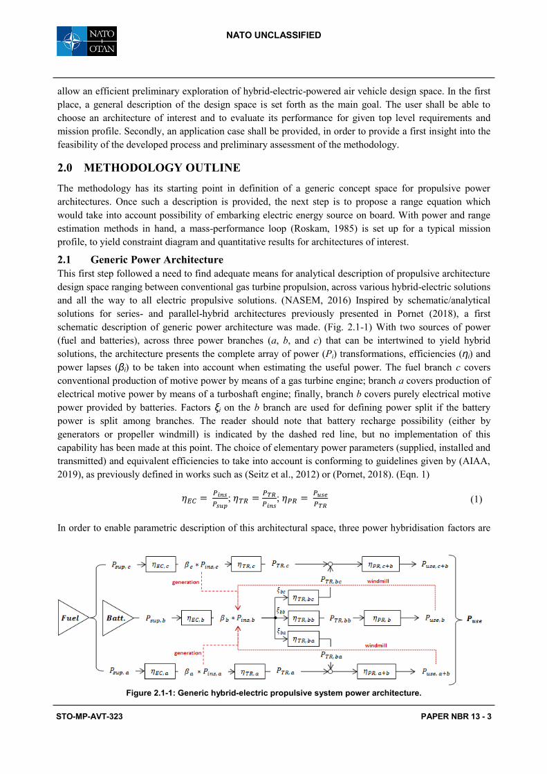
schematic description of generic power architecture was made. (Fig. 2.1-1) With two sources of power
(fuel and batteries), across three power branches (a, b, and c) that can be intertwined to yield hybrid
solutions, the architecture presents the complete array of power (Pi) transformations, efficiencies (ηi) and
power lapses (βi) to be taken into account when estimating the useful power. The fuel branch c covers
conventional production of motive power by means of a gas turbine engine; branch a covers production of
electrical motive power by means of a turboshaft engine; finally, branch b covers purely electrical motive
power provided by batteries. Factors ξi on the b branch are used for defining power split if the battery
power is split among branches. The reader should note that battery recharge possibility (either by
generators or propeller windmill) is indicated by the dashed red line, but no implementation of this
capability has been made at this point. The choice of elementary power parameters (supplied, installed and
transmitted) and equivalent efficiencies to take into account is conforming to guidelines given by (AIAA,
2019), as previously defined in works such as (Seitz et al., 2012) or (Pornet, 2018). (Eqn. 1)
;
;
(1)
In order to enable parametric description of this architectural space, three power hybridisation factors are
Figure 2.1-1: Generic hybrid-electric propulsive system power architecture.
C2 - Restricted
Generalised Methodology for Sizing of Air Vehicles with Hybrid-Electric Propulsion
PAPER NBR 13 - 4 STO-MP-AVT-323
NATO UNCLASSIFIED
proposed, inspired by degree of hybridisation for power parameter, as defined in Isikveren et al. (2014),
representing ratios between installed power on one of the respective branches and the total installed
power. (Eqn. 2)
(2)
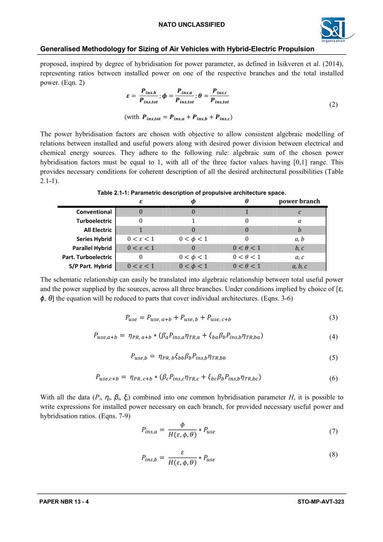
The power hybridisation factors are chosen with objective to allow consistent algebraic modelling of
relations between installed and useful powers along with desired power division between electrical and
chemical energy sources. They adhere to the following rule: algebraic sum of the chosen power
hybridisation factors must be equal to 1, with all of the three factor values having [0,1] range. This
provides necessary conditions for coherent description of all the desired architectural possibilities (Table
2.1-1).
Table 2.1-1: Parametric description of propulsive architecture space.
power branch
Conventional c
Turboelectric a
All Electric b
Series Hybrid a, b
Parallel Hybrid b, c
Part. Turboelectric a, c
S/P Part. Hybrid a, b, c
The schematic relationship can easily be translated into algebraic relationship between total useful power
and the power supplied by the sources, across all three branches. Under conditions implied by choice of [ε,
ϕ, θ] the equation will be reduced to parts that cover individual architectures. (Eqns. 3-6)
(3)
(4)
(5)
(6)
With all the data (Pi, ηi, βi, ξi) combined into one common hybridisation parameter H, it is possible to
write expressions for installed power necessary on each branch, for provided necessary useful power and
hybridisation ratios. (Eqns. 7-9)
(7)
(8)
C2 - Restricted
STO-MP-AVT-323 PAPER NBR 13 - 5
NATO UNCLASSIFIED
(9)
With:
( )
) (10)
This generic power relationship which takes into account elementary power transformations and losses
associated to processes and altitude effects is integrated into the mass-performance sizing loop which will
be presented in section 2.3.
While the ambition of such representation is to build a bridge between analytical quantitative analysis and
discrete architectural solution space, it is clear that quantitative nature of the equation is empirical, i.e. the
model is highly data-dependent for all that concerns parameters such as e.g. component efficiencies,
weights or battery power densities.
2.2 Range Equation
Constant battery mass as it discharges energy throughout mission will bear repercussions on range and
fuel weight estimation capabilities for hybrid-electric vehicles. To remedy this, a first attempt was made to
extend the conventional (i.e. for aeroplanes with fuel-based propulsion) Breguet range equation (Eqn. 11).
(
)
(11)
Where PSFC is the power-specific fuel consumption, and W0 and W1 are weights at start and end of cruise,
respectively. Using the same rationale as for derivation of the conventional range equation (i.e. cruise
conditions under hypothesis of constant lift-to-drag ratio and flight speed) an equivalent equation can be
derived for a battery-powered vehicle (Eqn. 12).
(12)
Where cb is the battery specific energy, η is the overall efficiency of the propulsion system, and Wbat and
W are battery weight and aircraft weight respectively. A hybrid energy system equation development
initiated through the W0/W1 term accounting. The idea is to see how much weight can be lost to the battery
presence, and then to add that effect at a later stage in order to obtain a complete weight accounting
capability. It is done by weighing the weight fraction by respective battery and fuel energy flows (Eqn.
13), which enables a simple distribution of power between purely fuel-produced power ( = 0) and
purely battery-produced power ( = 0).
( )
(13)
In this expression, is the fuel mass flow and is an equivalent fictitious parameter (Eqn. 14) which
deals with electric energy flow.
C2 - Restricted
Generalised Methodology for Sizing of Air Vehicles with Hybrid-Electric Propulsion
PAPER NBR 13 - 6 STO-MP-AVT-323
NATO UNCLASSIFIED
(14)
Replacing these back into Eqn. 13, and expressing respective useful powers along the fuel-based and
battery-based branches with the relations given by Eqns. 4 to 10, the following expression is obtained for
the conventional range:
(
) [
( )
] (15)
With Xf and Xe (Eqn. 16) being grouped efficiency, power hybridisation, specific energy and power lapse
terms.
[ ]
[ ]
(16)
With Eqn. 15 in hand, the user has a possibility to account for conventional range “lost” to the embarked
batteries and their constant mass. In turn, to account for how much range can be gained by the power
provided by the batteries, the same development is undertaken, this time starting with Eqn. 12, which
yields an expression for the range provided by the batteries (Eqn. 17).
(17)
Adding Eqn. 17 to Eqn. 15 yields the final range equation (Eqn. 18).
(
)
[ (
( )
)
]
(18)
While a hypothesis of linear addition of two contributions is rather simplistic and probably not
representative of performance to be expected in a real-life application, precedence was given to
constructing a first working version of the sizing tool, so this version of the equation was retained until
further refinement.
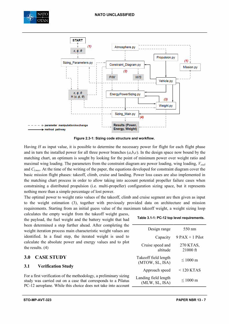
2.3 Workflow
The method is structured as a standard mission mass-performance loop calculation; the complete
workflow with associated process enumeration, illustrated with the sizing tool constituent modules, is
presented in Figure 2.3-1. It is initiated by introduction of top level requirements and mission parameters,
along with the propulsive architecture to be studied by selection of appropriate values of the power
hybridisation ratios (1). This information is then transferred to the constraint diagram calculation where
the matching chart us set up, which plots power over weight ratio as a function of the wing loading (2).
C2 - Restricted
STO-MP-AVT-323 PAPER NBR 13 - 7
NATO UNCLASSIFIED
Having H as input value, it is possible to determine the necessary power for flight for each flight phase
and in turn the installed power for all three power branches (a,b,c). In the design space now bound by the
matching chart, an optimum is sought by looking for the point of minimum power over weight ratio and
maximal wing loading. The parameters from the constraint diagram are power loading, wing loading, Vstall
and CLmax. At the time of the writing of the paper, the equations developed for constraint diagram cover the
basic mission flight phases: takeoff, climb, cruise and landing. Power loss cases are also implemented in
the matching chart process in order to allow taking into account potential propeller failure cases when
constraining a distributed propulsion (i.e. multi-propeller) configuration sizing space, but it represents
nothing more than a simple percentage of lost power.
The optimal power to weight ratio values of the takeoff, climb and cruise segment are then given as input
to the weight estimation (3), together with previously provided data on architecture and mission
requirements. Starting from an initial guess value of the maximum takeoff weight, a weight sizing loop
calculates the empty weight from the takeoff weight guess,
the payload, the fuel weight and the battery weight that had
been determined a step further ahead. After completing the
weight iteration process main characteristic weight values are
identified. In a final step, the iterated weight is used to
calculate the absolute power and energy values and to plot
the results. (4)
3.0 CASE STUDY
3.1 Verification Study
For a first verification of the methodology, a preliminary sizing
study was carried out on a case that corresponds to a Pilatus
PC-12 aeroplane. While this choice does not take into account
Figure 2.3-1: Sizing code structure and workflow.
Table 3.1-1: PC-12 top level requirements.
Design range 550 nm
Capacity 9 PAX + 1 Pilot
Cruise speed and
altitude
270 KTAS,
21000 ft
Takeoff field length
(MTOW, SL, ISA) ≤ 1000 m
Approach speed < 120 KTAS
Landing field length
(MLW, SL, ISA) ≤ 1000 m
C2 - Restricted
Generalised Methodology for Sizing of Air Vehicles with Hybrid-Electric Propulsion
PAPER NBR 13 - 8 STO-MP-AVT-323
NATO UNCLASSIFIED
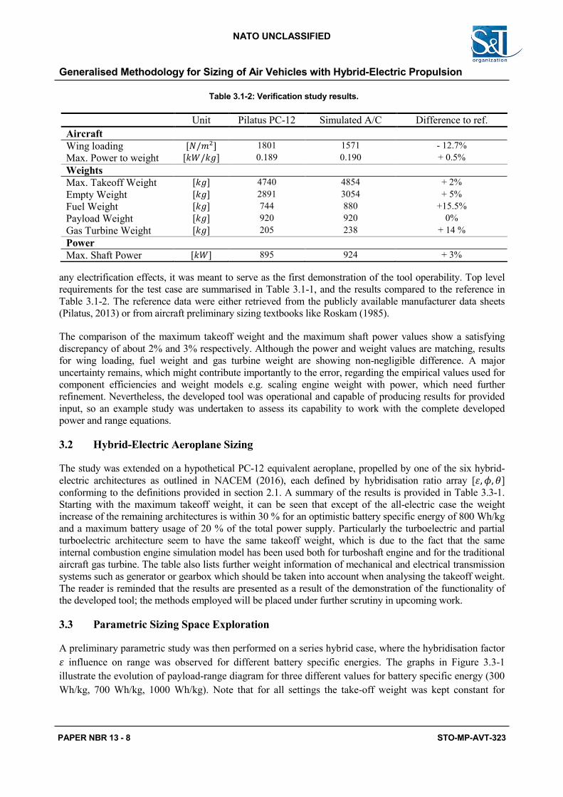
any electrification effects, it was meant to serve as the first demonstration of the tool operability. Top level
requirements for the test case are summarised in Table 3.1-1, and the results compared to the reference in
Table 3.1-2. The reference data were either retrieved from the publicly available manufacturer data sheets
(Pilatus, 2013) or from aircraft preliminary sizing textbooks like Roskam (1985).
The comparison of the maximum takeoff weight and the maximum shaft power values show a satisfying
discrepancy of about 2% and 3% respectively. Although the power and weight values are matching, results
for wing loading, fuel weight and gas turbine weight are showing non-negligible difference. A major
uncertainty remains, which might contribute importantly to the error, regarding the empirical values used for
component efficiencies and weight models e.g. scaling engine weight with power, which need further
refinement. Nevertheless, the developed tool was operational and capable of producing results for provided
input, so an example study was undertaken to assess its capability to work with the complete developed
power and range equations.
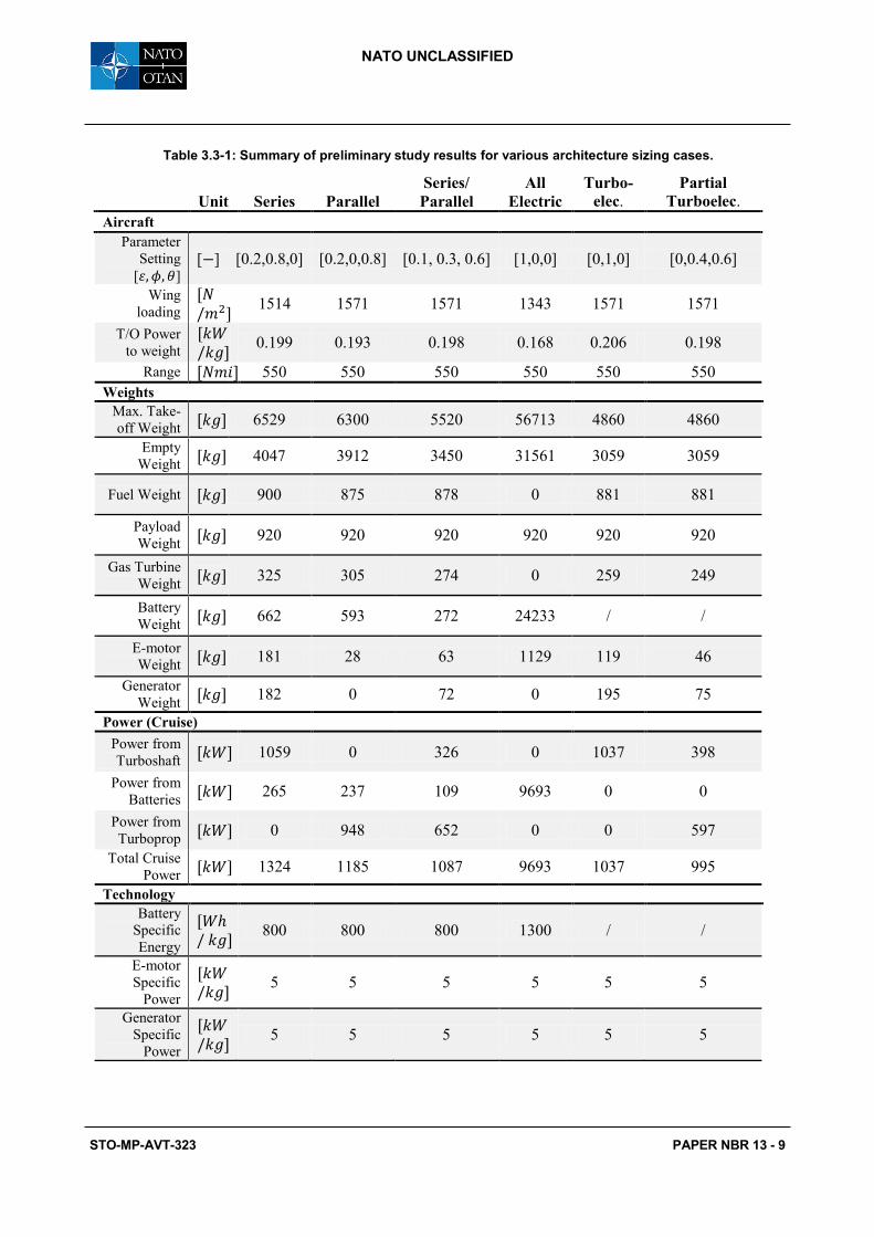
3.2 Hybrid-Electric Aeroplane Sizing
The study was extended on a hypothetical PC-12 equivalent aeroplane, propelled by one of the six hybrid-
electric architectures as outlined in NACEM (2016), each defined by hybridisation ratio array [ ]
conforming to the definitions provided in section 2.1. A summary of the results is provided in Table 3.3-1.
Starting with the maximum takeoff weight, it can be seen that except of the all-electric case the weight
increase of the remaining architectures is within 30 % for an optimistic battery specific energy of 800 Wh/kg
and a maximum battery usage of 20 % of the total power supply. Particularly the turboelectric and partial
turboelectric architecture seem to have the same takeoff weight, which is due to the fact that the same
internal combustion engine simulation model has been used both for turboshaft engine and for the traditional
aircraft gas turbine. The table also lists further weight information of mechanical and electrical transmission
systems such as generator or gearbox which should be taken into account when analysing the takeoff weight.
The reader is reminded that the results are presented as a result of the demonstration of the functionality of
the developed tool; the methods employed will be placed under further scrutiny in upcoming work.
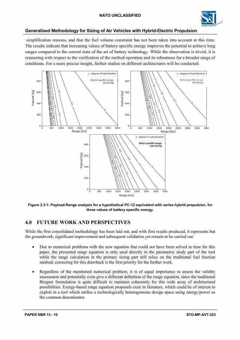
3.3 Parametric Sizing Space Exploration
A preliminary parametric study was then performed on a series hybrid case, where the hybridisation factor
influence on range was observed for different battery specific energies. The graphs in Figure 3.3-1
illustrate the evolution of payload-range diagram for three different values for battery specific energy (300
Wh/kg, 700 Wh/kg, 1000 Wh/kg). Note that for all settings the take-off weight was kept constant for
Table 3.1-2: Verification study results.
Unit Pilatus PC-12 Simulated A/C Difference to ref.
Aircraft
Wing loading 1801 1571 - 12.7%
Max. Power to weight 0.189 0.190 + 0.5%
Weights
Max. Takeoff Weight 4740 4854 + 2%
Empty Weight 2891 3054 + 5%
Fuel Weight 744 880 +15.5%
Payload Weight 920 920 0%
Gas Turbine Weight 205 238 + 14 %
Power
Max. Shaft Power 895 924 + 3%
C2 - Restricted
STO-MP-AVT-323 PAPER NBR 13 - 9
NATO UNCLASSIFIED
Table 3.3-1: Summary of preliminary study results for various architecture sizing cases.
Unit Series Parallel
Series/
Parallel
All
Electric
Turbo-
elec. Partial
Turboelec.
Aircraft
Parameter
Setting
[ ] [ ] [0.2,0.8,0] [0.2,0,0.8] [0.1, 0.3, 0.6] [1,0,0] [0,1,0] [0,0.4,0.6]
Wing
loading
1514 1571 1571 1343 1571 1571
T/O Power
to weight
0.199 0.193 0.198 0.168 0.206 0.198
Range 550 550 550 550 550 550
Weights
Max. Take-
off Weight 6529 6300 5520 56713 4860 4860
Empty
Weight 4047 3912 3450 31561 3059 3059
Fuel Weight 900 875 878 0 881 881
Payload
Weight 920 920 920 920 920 920
Gas Turbine
Weight 325 305 274 0 259 249
Battery
Weight 662 593 272 24233 / /
E-motor
Weight 181 28 63 1129 119 46
Generator
Weight 182 0 72 0 195 75
Power (Cruise)
Power from
Turboshaft 1059 0 326 0 1037 398
Power from
Batteries 265 237 109 9693 0 0
Power from
Turboprop 0 948 652 0 0 597
Total Cruise
Power 1324 1185 1087 9693 1037 995
Technology
Battery
Specific
Energy
800 800 800 1300 / /
E-motor
Specific
Power
5 5 5 5 5 5
Generator
Specific
Power
5 5 5 5 5 5
C2 - Restricted
Generalised Methodology for Sizing of Air Vehicles with Hybrid-Electric Propulsion
PAPER NBR 13 - 10 STO-MP-AVT-323
NATO UNCLASSIFIED
simplification reasons, and that the fuel volume constraint has not been taken into account at this time.
The results indicate that increasing values of battery specific energy improves the potential to achieve long
ranges compared to the current state of the art of battery technology. While the observation is trivial, it is
reassuring with respect to the verification of the method operation and its robustness for a broader range of
conditions. For a more precise insight, further studies on different architectures will be conducted.
Figure 3.3-1: Payload-Range analysis for a hypothetical PC-12 equivalent with series hybrid propulsion, for
three values of battery specific energy.
4.0 FUTURE WORK AND PERSPECTIVES
While the first consolidated methodology has been laid out, and with first results produced, it represents but
the groundwork; significant improvement and subsequent validation yet remain to be carried out:
Due to numerical problems with the new equation that could not have been solved in time for this
paper, the presented range equation is only used directly in the parametric study part of the tool
while the range calculation in the primary sizing part still relies on the traditional fuel fraction
method; correcting for this drawback is the first priority for the further work.
Regardless of the mentioned numerical problem, it is of equal importance to assess the validity
assessment and potentially even give a different definition of the range equation, since the traditional
Breguet formulation is quite difficult to maintain coherently for this wide array of architectural
possibilities. Exergy-based range equation proposals exist in literature, which could be of interest to
exploit in a tool which unifies a technologically heterogeneous design space using energy/power as
the common denominator.
C2 - Restricted
STO-MP-AVT-323 PAPER NBR 13 - 11
NATO UNCLASSIFIED
Including recharging capability for the batteries, in order to enable more versatile mission profiles.
Including nonpropulsive power off-takes.
Developing sensitivity analysis capabilities for the tool.
In the long run, developing optimisation capabilities for the tool, as for the time being the
architectural choice is uniquely a matter of user input.
It is worth mentioning that the tool is also conceived for tackling Boundary Layer Ingestion propulsion
related problems, which was judged to be beyond the scope of this paper. Further work equally includes
consolidation and upgrade of these aspects.
5.0 CONCLUSION
The paper presents a first attempt at creating a preliminary sizing tool for aeroplanes with propulsive
architectures ranging between typical gas turbines and different (hybrid) electric options, based on the classic
Roskam semi-empirical mass-performance loop method. To this purpose, a generic power architecture is
outlined, which in turn yields generic equation for determination of installed power needed on the different
power branches. The architecture is analytically described by an array of three power hybridisation ratios,
one for each propulsive power production scenario: mechanical (gas turbine engine), electrical (battery
driven propellers and electrical to mechanical (electrical power produced by a turboshaft). A simple
composite range equation is then given, in order to enable taking into account electrical energy sources
(batteries) along with fuel-based power. These corrections are introduced into conventional matching chart
method directly for the parametric studies, and for the time being indirectly for the basic sizing study,
through separate calculations of weight fractions to be used in the traditional Breguet equation.
Preliminary verification case shows decent match of obtained results to the reference Pilatus PC-12 data,
except for the fuel weight and wing loading; this discrepancy is strongly to be due to the nature of the
developed range equation. Results for different hybrid-electric architectures, the same mission and same
payload and range indicate the most performing architectures to be the parallel hybrid and series hybrid,
while all electric architecture underperforms by far, even with increased battery specific energy. First
preliminary studies on series hybrid architecture payload-range relationship show an expected degrading
effect of hybridisation relative to all-fuel alternative, which can be somewhat offset with higher battery
specific energy. While it yet remains to significantly improve the methodology, as well as the parameter
databases behind its semi-empirical models, its potential to enable quick and efficient design space
exploration at preliminary sizing level is already tangible.
Concerning potential military significance of the presented work, its flexibility with respect to mission
profiles makes it suitable for civilian and military aircraft applications alike. However, any such divergence
at this time would also require tempering with the equations, as well as significant performance database
upgrade. For example at this level of the tool maturity, surveillance-type drones are feasible as target
applications; for more different applications and mission than that, e.g. weapon-carrying vehicles, significant
upgrades will be needed.
6.0 ACKNOWLEDGMENTS
The authors would like to thank John Eshagh Saetlou for his valuable contribution to this work. The
gratitude is extended to SAFRAN Group for providing means that made this work possible through
“AEGIS” research grant, as well as to Dr. Askin T. Isikveren for his continuous encouragement and support
for this paper.
C2 - Restricted
Generalised Methodology for Sizing of Air Vehicles with Hybrid-Electric Propulsion
PAPER NBR 13 - 12 STO-MP-AVT-323
NATO UNCLASSIFIED
7.0 REFERENCES
Airbus (2018), “The future is electric”, available at:
https://www.airbus.com/newsroom/news/en/2018/07/the-future-is-electric.html (accessed on 1 July 2019)
Aircraft Electric Propulsion and Power (AEPP) Working Group (2019) Guidelines for Analysis of Hybrid
Electric Aircraft System Studies: Nomenclature, Pictographic Representations, Standalone and Combined
Properties and Attributes, Metrics, and Figures of Merit, AIAA, available at:
https://www.aiaa.org/docs/default-source/uploadedfiles/publications/standards/hybrid-
electric_properties_attributes.pdf?sfvrsn=c8eb8f11_0
Bijewitz, J., Seitz, A., Hornung, M. (2016),”A Review of Recent Aircraft Concepts Employing Synergistic
Propulsion-Airframe Integration”, paper presented at the Congress of the International Council of the
Aeronautical Sciences (ICAS), 26-29 September, Daejeon, Korea.
Brelje, B. J., Martins, J. R. R. A. (2019), Electric, Hybrid, and Turboelectric Fixed-Wing Aircraft: A Review
of Concepts, Models, and Design Approaches, Progress in Aerospace Sciences, 104, 1-19,
doi:10.1016/j.paerosci.2018.06.004
C. Pornet (2018), Conceptual Design Methods for Sizing and Performance of Hybrid-Electric Transport
Aircraft, PhD dissertation, Technische Universität München – Fakultät für Maschinenwesen, Munich,
Germany, available at: https://mediatum.ub.tum.de/1399547
Elmousadik, S., Ridard, V., Sécrieru, N., Joksimovic, A., Maury, C., Carbonneau, X. (2018), “New
Preliminary Sizing Methodology for a Commuter Airplane with Hybrid-Electric Distributed Propulsion”,
paper presented at Advanced Aircraft Efficiency in a Global Air Transport System (AEGATS) Conference,
23-25 October 2018, Toulouse, France.
Gohardani, A.S. (2013), A synergistic glance at the prospects of distributed propulsion technology and the
electric aircraft concept for future unmanned air vehicles and commercial/military aviation, Progress in
Aerospace Sciences 57, 25-70, https://doi.org/10.1016/j.paerosci.2012.08.001
Isikveren, A.T., Kaiser, S., Pornet, C., Vratny, P.C. (2014), Pre-design Strategies and Sizing Techniques for
Dual-Energy Aircraft, Aircraft engineering and aerospace technology, 86(6), 525-542, doi:10.1108/AEAT-
08-2014-0122
Isikveren, A.T., Fefermann, Y., Maury, C., Level, C., Zarati, K., (…) Thoraval, B. (2018), Pre-design of a
Commuter Transport Utilising Voltaic-Joule/Brayton Motive Power Systems, Aeronautical Journal -New
Series- 122(1248), 205-237. DOI: 10.1017/aer.2017.126
Kim, D.H. (2010), “Distributed Propulsion Vehicles”, paper presented at the 27th Congress of the
International Council of the Aeronautical Sciences (ICAS), 19-24 September, Nice, France.
Lagha M., Duplaa S., Binder N., Carbonneau X., Rodriguez B. (2019), “Similarity Study of Lightly Loaded
Shrouded Rotors for Distributed Propulsion”, paper presented at ASME Turbo Expo 2019, 17-21 June,
Phoenix, AZ, USA.
National Academies of Sciences, Engineering, and Medicine (2016), “Commercial Aircraft Propulsion and
Energy Systems Research: Reducing Global Carbon Emissions”, National Academies Press, Washington,
DC, USA. DOI: 10.17226/23490.
Pilatus (2013), “PC-12 NG Just the Facts”, available at: http://www.synerjet.com/assets/pc-12-
justthefacts.pdf (consulted 1 July 2019)
C2 - Restricted
STO-MP-AVT-323 PAPER NBR 13 - 13
NATO UNCLASSIFIED
Roskam, J. (1985), Airplane Design, Part I, Roskam Aviation and Engineering Corporation, Ottawa, USA.
Sampson, B. (2018), “Zunum confirms flight testing schedule for hybrid-electric aircraft”, available at:
https://www.aerospacetestinginternational.com/news/electric-hybrid/zunum-confirms-flight-testing-
schedule-for-hybrid-electric-aircraft.html (accessed on 1 July 2019)
Seitz, A., Schmitz, O., Isikveren, A.T., Hornung, M. (2012), “Electrically Powered Propulsion: Comparison
and Contrast to Gas Turbines”, paper presented at Deutscher Luft- und Raumfahrtkongress, 10-12
September, Berlin, Germany.
Sinnett, M. (2007), “787 No-Bleed Systems: Saving Fuel and Enhancing Operational Efficiencies”, Boeing
Aero Magazine Issue 28, The Boeing Company, available at:
https://www.boeing.com/commercial/aeromagazine/articles/qtr_4_07/article_02_1.html (accessed on 1st of
July 2019)
C2 - Restricted
Generalised Methodology for Sizing of Air Vehicles with Hybrid-Electric Propulsion
PAPER NBR 13 - 14 STO-MP-AVT-323
NATO UNCLASSIFIED