Embed Size (px)
Citation preview

GS 01R4B04-00E-E
PRINCIPLE OF MEASUREMENTMass flow measurement according to the Coriolis principle. For abrasive or highly corrosive fluids please contact your Yokogawa representative.
3 SeriesCoriolis Mass Flow and Density MeterFOUNDATION™ Fieldbus Communication
GS 01R04B05-00E-E©Copyright June 2005 (RYG19th edition, July 2017 (RYG
Rota Yokogawa GmbH & Co. KGRheinstr. 8D-79664 WehrGermany
GeneralSpecifications
RCCT39/XR RCCT34 - 39/IR RCCF31 + RCCS34 - 39/IR RCCS30LR-33
ROTAMASS is a Coriolis mass flowmeter with highly refined digital signal processing electronics, so that accurate and stable mass flow measurement is achieved.
ROTAMASS employs a flame-proof type converter case suitable for use in the hazardous area together with it’s intrinsic safety type detector.
ROTAMASS´s signal processing, housing protection and its detector´s special decoupling system against external loads and vibrations, realize high performance in real applications.
FOUNDATION™ Fieldbus is the digital communication line for field instruments, whose signal is internationally standardized by the Fieldbus Foundation organization.
The fieldbus bi-directional digital communication performance makes it possible for field instruments and control devices to constitute a complete on-line system, superseding the existing analog transmission lines. Also, the precise trans-mission of various process data of the field instruments is well established by the fieldbus multi-sensing function. Thus, based on FOUNDATION™ Fieldbus specifications, the ROTAMASS 3 series fieldbus models offer more flexible instrumentation through a greater level communication capability as well as cost reduction by multi-drop wiring with fewer cables.
GS 01R04B05-00E-E
Contents
Principle of measurement Page 1
Features Page 2
Intended Use Page 2
Performance specifications Page 3
Normal operating conditions Page 4
Mechanical specifications Page 6
Electrical specifications Page 6
Remote cable RCCY03 specification Page 6
CE Declaration Page 6
Hazardous area specifications Page 8
Planning and installation hints Page 12
Factory Setting Page 15
Ordering Information Page 15
Dimensions Page 16
Model-, suffix- and option- codes Page 24
Related instruments Page 29

GS 01R04B05-00E-E 19th edition July 22, 2017-00
2
All Rights Reserved. Copyright © 2005, Rota Yokogawa
PERFORMANCE SPECIFICATIONSModel- Remote detector RCCS30LR to 33: 2 tubes, low flow design - Remote detector RCCS34 to 39/XR : 2 tube design - Remote field-mount converter RCCF31- Integral type RCCT34 to 39/XR: 2 tube design
Fluid to be measured : Liquid, gas or slurry
Measurement Items : Mass flow, density, temperature and derived from these values: concentration, volume flow and net flow
Mass Flow MeasurementTable 1: measuring range
ModelRCCS30
LRRCCS30 RCCS31 RCCS32 RCCS33
Qmax t/h 0.04 0.094 0.3 0.6 1.5lb/h 88 207 661 1322 3307
Qnom t/h 0.021 0.045 0.17 0.37 0.95lb/h 46 99 374 815 2094
Model RCC34 RCC36 RCC38 RCC39RCC39
/IRRCC39
/XR
Qmaxt/h 5 17 50 170 300 600
lb/h 11023 37478 110231 374785 661386 1322773
Qnomt/h 3 10 32 100 250 500
lb/h 6613 22046 70547 220462 551155 1102311
Qnom is the water flow rate at about 1 bar pressure drop.The flowmeter has a default low cut of 0.05% of Qnom.
Accuracy of mass flow (refer to table 2): Liquid RCCS30LR - 39/XR: ± 0.1% of flow rate ± zero stability / flow rate *100% Gas (option /GA): ± 0.5% of flow rate ± zero stability / flow rate *100%
Accuracy of volume flow : SQRT ( (mass flow error in %)² + (density error in %)²)
Accuracy based on the frequency output includes the combined effects of repeatability, linearity and hysteresis.
Repeatability for liquids: ± 0.05% ± (zero stability/2) / flow rate *100%
Table 2 : Zero Stability
ModelRCCS30
LR RCCS30 RCCS31 RCCS32 RCCS33
kg/h 0.003 0.005 0.0085 0.019 0.048
lb/h 0.006 0.011 0.018 0.04 0.105
Model RCC34 RCC36 RCC38 RCC39 RCC39 /IR
RCC39 /XR
kg/h 0.15 0.5 1.6 5 13 25
lb/h 0.33 1.1 3.5 11 28.6 55
FEATURES • ROTAMASS is a flowmeter for nearly all fluids, including high viscosity liquids, slurries and multi- phase media with a certain gas content• Field-mount remote converter available
• Refined digital signal processing enables accurate and stable measurement• A special detector decoupling system makes the device highly independent from external loads or vibrations.• Simple flow path means self-draining, simple cleaning and suitable for use in hygenic industries.• High accuracy and high stability over a wide flow range • Accurate density measurement, up to +/- 0.0005 g/cm³• Temperature measurement• Concentration measurement for solutions, suspensions and emulsions (e.g. water cut, net oil computing)• Volume flow with reference density• Available in explosion proof versions (ATEX, FM, IECEx, EAC, INMETRO, NEPSI, KOSHA)• Wide process temperature range –200°C to 350°C • Microprocessor-based multifunction capability• EEPROM protects parameter settings and totalized values during power failure• High visibly LCD display• FOUNDATION™ Fieldbus communication • Optional intrinsicallyally safe FF-output• Various choice of tubes materials • EN, ASME or JIS flanges as standard, others on request• Interoperability FOUNDATION™ Fieldbus specifications ensures interoperability of the field instruments without the requirement for designated software for the instrument.• Reduction of Instrumentation Cost The multi-drop wiring on the fieldbus communication line contributes to the reduction of wiring costs.• 6 Analog input function blocks (AI) The ROTAMASS 3 series fieldbus model has 4 independent AI function blocks for mass flow, volume flow, density and temperature calculation. 2 AI function blocks for concentration measurement and net flow calculation are available as option.• 2 Integrator function blocks (IT) The ROTAMASS 3 series fieldbus model has 2 independent IT function blocks for mass, volume or net totalization. • Alarm function The ROTAMASS 3 series fieldbus model securely support various alarm functions, such as high/low alarm, notice of block error, etc. based on FOUNDATION™ Fieldbus specification.• Self-diagnostic function The reliable self-diagnostic function detects the measuring range failure, hardware failure, or parameter range violation.• Link master function The ROTAMASS 3 series fieldbus models support the Link Master function. This function enables backup of network manager and local control only by field devices.• Proportional-integral-derivative function block (PID) PID function block enables field devices to control processes. • Software download function The software download enables the update of communication software during operational conditions.
-1.0-0.9-0.8-0.7-0.6-0.5-0.4-0.3-0.2-0.1
00.10.20.30.40.50.60.70.80.91.0
0 50 100 150
Flow in % of Qnom
Erro
r in
%
F10.EPS

GS 01R04B05-00E-E 19th edition July 22, 2017-00
3
All Rights Reserved. Copyright © 2005, Rota Yokogawa
Pressure DependencyThe stiffness of the ROTAMASS tubes is slightly line pressure dependent. The static pressure effect of mass flow and density can be corrected by setting the static pressure manually via menu.
Table 3 : Static pressure effect on mass flow (if not corrected)
ModelRCCS30
LR RCCS30 RCCS31 RCCS32 RCCS33
% of rate per bar / (psi)
SH0.00000 /(0.0)
0.00000 /(0.0)
0.00012 /(0.00174)
0.00246 / (0.03568)
0.0035 / (0.0508)
HC ---- ---- ---- ---- ----
Model RCC34 RCC36 RCC38 RCC39 RCC39 /IR
% of rate per bar / (psi)
SL0.00081 / (0.01175)
0.00346 / (0.05018)
0.00950 / (0.1378)
0.01058 / (0.15345)
0.0047 / (0.0682)
HC0.00084 / (0.01218)
0.00336 /(0.04873)
0.00896 / (0.12995)
0.00808 / (0.11719)
0.00287 / (0.04163)
Model RCC39 /XR
% of rate per bar / (psi)
SL0.00740 / (0.1073)
HC ----
Density MeasurementAdjustment with water and air at calibration temperature.Measuring range: RCCS30LR - 38: 0.3 kg/l to 5 kg/l RCC39 -39/XR : 0.3 kg/l to 2 kg/lNo density measurement for gas applications.With option /K4 thermal stabilization is acquired.For further details about the option /K6 please refer to “special calibrations” on page 3.Calibration condition standard Density : 0.9 kg/l ≤ r ≤ 1.1 kg/l Temp. Fluid : 22.5°C ± 12.5°C Flow Rate : about 0.2 * Qnom as defined for each modelCalibration condition for /K6: Density : 0.7 kg/l ≤ r ≤ 1.65 kg/l Temp. Fluid : 20°C ≤ T ≤ 80°C Temp. Ambient : 20°C ± 3K Flow Rate : about 0.2 * Qnom as defined for each model
Table 4: Accuracy (at calibration conditions):
Model Standard Option /K4 Option /K6
RCCS30LR 0.02 g/cm³ *) ------ ------
RCCS30 0.008 g/cm³ *) ------ ------
RCCS31 0.004 g/cm³ 0.001 g/cm³ ------
RCCS32 0.004 g/cm³ 0.001 g/cm³ 0.0005 g/cm³
RCCS33 0.004 g/cm³ 0.001 g/cm³ 0.0005 g/cm³
RCC34 0.003 g/cm³ 0.001 g/cm³ 0.0005 g/cm³
RCC36 0.0022 g/cm³ 0.001 g/cm³ 0.0005 g/cm³
RCC38 0.0015 g/cm³ 0.001 g/cm³ 0.0005 g/cm³
RCC39 0.0015 g/cm³ 0.001 g/cm³ 0.0005 g/cm³
RCC39/IR 0.0015 g/cm³ ------ ------
RCC39/XR 0.0015 g/cm³ ------ ------ Repeatability: RCCS32-33, RCC34-39/XR : ± 0.0005 g/cm³ (Std, /K4)Static pressure effect: Compensated if static pressure is set in the menu.
Specification of high performance density measurement option /K6: Density calibration Density range : 0.3 to 2.5 kg/l Ambient temp. range : -10°C to 50°C (14°F to 122°F) Process temp. range Standard: -50°C to 150°C (58°F to 302°F) Process temp. range /HT: 150°C to 350°C (302°F to 662°F) Minimum flow rate for specified accuracy: - RCC36 to RCC39 : 700 kg/h (1543 lb/h) - RCC34 : 140 kg/h (308 lb/h) - RCCS33 : 90 kg/h (198 lb/h) - RCCS32 : 37 kg/h (81 lb/h) Maximum flow rate : Qnom Repeatability : ±0.0002 g/cm³ Temperature measurement: ±(0.5°C+0.002*abs(Tmedium-20°C)) (not /HT) ±(0.5°C+0.008*abs(Tmedium-20°C)) (/HT) Density accuracy : only for liquids, one phase Process temperature influence : ±0.000015 g/cm³ * abs(Tmedium-20°C)
Temperature Measurement Temperature measuring range of converter :Standard, /LT, /MT : -200°C to 230°C (-328°F to 448°F)Option /HT : 0°C to 350°C (32°F to 662°F)Accuracy:Standard (-70°C to 150°C / -94°F to 302°F) : ±(0.5°C+0.005*abs(Tmedium-20°C))Option /LT (-200°C to 150°C / -328°F to 302°F) : ±(1.0°C+0.008*abs(Tmedium-20°C))Option /MT (-70°C to 260°C / -94°F to 500°F) : ±(0.5°C+0.005*abs(Tmedium-20°C))Option /HT (0°C to 350°C / 32°F to 662°F) : ±(1.0°C+0.008*abs(Tmedium-20°C))For process temperatures more than 80°C (176°F) higher/lower than ambient temperature the detector should be insu-lated to maintain optimum accuracy.
Heat Tracing Heating with heat carrier, insulation and protection housing. Typically the max. surface temperature at the protection housing from inner heating is 40°C (at Tamb = 20°C). Above 150°C (302°F) process temperature insulation from the manufacturer is recommended. However up to 230°C (446°F) process temperature the customer can insulate the detector himself. For this case order option /S2.Option /T1 : only insulation and protection Option /T2 : insulation, protection and heating line Option /T3 : like /T2 but with ventilationProcess connection for the heat carrier fluid (see table 10):for D-type flanges : EN DN 15 PN 40 Form B1for A-type flanges : ANSI ½ - 150 lbs.for J-type flanges : JIS DN15 10KMax. pressure : PN 40Protection class : IP54, install roof protectedFor fluid temperatures below -70°C select option /LT.
Calibration for Liquids and Gases The ROTAMASS flowmeters are always factory calibrated with water. Calibration Conditions: - Water : 22.5°C ± 12.5°C (72.5°F ± 22.5°F)- Ambient temperature : 22.5°C ± 12.5°C (72.5°F ± 22.5°F)- Process pressure : 1 to 2 bar abs- Installation: RCCS30LR to RCC38 vertical RCC39 to RCCS39/XR horizontal All specifications are based on above mentioned calibration reference conditions, a flow calibration protocol is attached to each instrument.

GS 01R04B05-00E-E 19th edition July 22, 2017-00
4
All Rights Reserved. Copyright © 2005, Rota Yokogawa
Special Calibrations - Mass-/Volume flow calibration with factory certificate (option /K2): Calibration with water at customer specified flow values according calibration order sheet.- Mass-/Volume flow calibration with/DAkkS certificate EN17025 (option /K5): Calibration with water at customer specified flow values according calibration order sheet.- Density calibration with factory certificate (option /K6): Adjustment and check with 3 different fluids, fluid temperature influence adjustment for low ambient temperature influence and thermal treatment for long term density measurement stability, improved temperature measurement accuracy (see also page 12).
Dual Seal Approval (Option /DS)- Conform with ANSI/ISA-12.27.01.- To be ordered if compliance with ANSI/ISA 12.27.01 is required.- Up to ANSI class 900 line pressure.- Only with FM approval option.- For liquid application the leakage detection is realized by software in the converter.- For gas application options /GA and /RD (rupture disk) are mandatory. - Rupture disk is only for annunciation.
NORMAL OPERATING CONDITIONSAmbient Temperature Ranges - Remote detector RCCS3: Standard : -50°C to +80°C (-58°F to 176°F) Option /LT : -50°C to +80°C (-58°F to 176°F) Option /MT : -50°C to +80°C (-58°F to 176°F) Option /HT : -50°C to +65°C (-58°F to 149°F) (up to 280°C (536°F) medium temperature) -50°C to +55°C (-58°F to 131°F) (up to 350°C (662°F) medium temperature) Terminal box temperature should not exceed 100°C - Remote converter RCCF31 and integral type RCCT3: Display operating range : -20°C to +55°C (-4°F to 131°F) Electronic operating range : -40°C to +55°C (-40°F to 131°F) Cold start : above -30°C (-22°F) Where meters are mounted in direct sunlight, it is recom-mended to install a sunshade. This is particularly important in countries with high ambient temperatures.
Ambient Humidity Range : 0 to 95% RH
Process Temperature Ranges
Detector : - RCCS30LR to 33 : -50°C to 150°C (-58°F to 302°F) - RCCS30LR to 33 /MT : -50°C to 260°C (-58°F to 500°F) - RCCS34 to 39/XR : -70°C to 150°C (-94°F to 302°F) - RCCS34 to 39/XR /LT : -200°C to 150°C (-328°F to 302°F) - RCCS34 to 39/XR /MT : -70°C to 230°C (-94°F to 446°F) (Range 150°C - 230°C (302°F to 446°F) recommended with /T option)- RCCS34 to 39/IR /HT : 0°C to 350°C (32°F to 662°F) (only with /T option or with /S2 and customer insulation)- RCCS39/XR /HT : 0°C to 350°C (32°F to 662°F) (only with /S2 and customer insulation)Integral type :- RCCT34 to 39/XR : -50°C to 150°C (-58°F to 302°F)
For use in hazardous area see “Hazardous Area Specifications”
Heat Carrier Fluid Temperature Ranges(Option /T2 or /T3 only for remote type RCCS30LR to 39/IR)- Standard : 0°C to 150°C (32°F to 302°F) - With option /MT (RCCS30LR to 33) : 0°C to 200°C (32°F to 392°F) - With option /MT (RCCS34 to 39/IR) : 0°C to 230°C (32°F to 446°F) - With option /HT : 0°C to 350°C (32°F to 662°F)
Process Pressure RangeIn dependance of the process connections s. table 9.On request following maximum pressure up to 27°C (RT=Room Temp.):
Material wetted parts SH [bar] / (psi)
SL [bar] / (psi)
HC [bar] / (psi)
RCCS30LR 400 / (5801) ---- ----
RCCS30 400 / (5801) ---- ----
RCCS31 350 / (5076) ---- ----
RCCS32 285 / (4183) ---- ----
RCCS33 285 / (4183) ---- ----
RCCS34 / RCCT34 ---- 260 / (3770) 385 / (5583)
RCCS36 / RCCT36 ---- 210 / (3045) 315 / (4568)
RCCS38 / RCCT38 ---- 175 / (2538) 260 / (3770)
RCCS39 / RCCT39 ---- 135 / (1958) 260 / (3770)
RCCS39/IR / RCCT39/IR ---- 110 / (1595) 180 / (2610)
RCCS39/XR / RCCT39/XR ---- 95 / (1377) ----
For higher medium temperatures maximum tube pressure needs to be derated as follows : up to 50°C (122°F) : 4% derating 51 to 100°C (123.8°F to 212°F) : 11% derating 101 to 150°C (213.8°F to 302°F) : 20% derating 151 to 230°C (303.8°F to 446°F) : 30% derating 231 to 350°C (447.8°F to 662°F) : 38% deratingHigher pressure on request.Higher pressure on request.The maximum process pressure of a single instrument is given by the lower value either of the process connections (table 9) or tubes. The maximum temperature and process pressure range of an instrument are marked on the nameplate as TS and PS.The given temperature/pressure ranges are calculated and approved without corrosion or erosion effects. The customer is fully responsible of selecting proper materials which with-stand corrosive or erosive conditions. In case of heavy corrosion and/or erosion the instrument may not withstand the pressure and an incident may happen with human and/or environmental harm. Yokogawa will not take any liability regarding damage caused by corrosion / erosion. If corrosion / erosion may happen, the user has to check periodically if the necessary wall thickness is still in place.

GS 01R04B05-00E-E 19th edition July 22, 2017-00
5
All Rights Reserved. Copyright © 2005, Rota Yokogawa
Gas Content Range for Liquid/Gas Mixtures Gas content limit is defined as the amount of gas in a liquid/gas mixture which generates an error in the converter. The gas content limit is dependent on viscosity, surface tension and bubble size of the liquid/gas mixture. Furthermore it is highly flow rate dependent (the higher the flow rate, the lower the gas content range). The stated values are for a flow of 50% of Qnom and water/air without /HP:
Model Gas content limit
RCCS30LR to RCCS32 no limitation
RCCS33 non-Ex type no limitation
RCCS33 Ex type approx. 35%
RCC34 no limitation
RCC36 approx. 50%
RCC38 approx. 30%
RCC39 approx. 7%
RCC39/IR approx. 3%
RCC39/XR (with /HP) approx. 2%
With option /HP the gas content range are improved.With liquid/gas mixtures the specified mass flow accuracy will not be achieved.For short time aeration a function can be activated to keep the current outputs constant during the aeration time.
Secondary Containment
Model Typical rupture pressure
Option /J1 pressure test *)
RCCS30LR-33 65 bar / (942 psi) ---RCC34-36 120 bar / (1740 psi) 60 bar / (870 psi)RCC38 120 bar / (1740 psi) 40 bar / (580 psi)RCC39 80 bar / (1160 psi) 10 bar / (145 psi)RCC39/IR 50 bar / (725 psi) ---RCC39/XR on request ---RCC39/XR/HT 50 bar / (725 psi) ---
*) Pressure test with safety factor S=1.1If the detector housing is exposed to a pressure close to the rupture pressure it will deform and measurement will be strongly influenced. Therefore the pressure test of the hous-ing (option /J1) can only be done at the pressure where de-formation does not happen.
Other 2 Phase Flow, liquid/solid and liquid/liquidTwo phase flow can generate minus span errors. The errors are proportional to the difference in density between the 2 phases and the amount of the second phase. If the particles (or droplets) are very small no errors will be generated.
MECHANICAL SPECIFICATIONSProtection Class - RCCT3 : IP66/67- RCCF31 : IP66/67- RCCS3 : IP66/67
Materials- Detector housing : Stainless steel 304/1.4301- Detector terminal box : 316L/1.4404 - Detector gas filling plug: 1.4305- Detector insulation housing : Stainless steel 304/1.4301- Detector rupture disk (/RD) : 316L - Field- mount converter housing : Aluminium alloy with Polyurethane corrosion-resistant coating or epoxy coating (option /X1) - Field- mount converter mounting bracket: : Stainless steel 304/1.4301- Name plates : Stainless steel 304/1.4301 Coating Color- Converter case : Mint green
Wetted Parts- RCCs30LR to 33 : Measuring tubes : Ni-Alloy C-22/2.4602 Process connections : 316L / 1.4404- RCC34 to 39/IR : Measuring tubes and process connection : 316L / 1.4404/1.4435 or Measuring tubes and flange face : Ni-Alloy C-22/2.4602- RCC39/XR : Measuring tubes and process connection : 316L/1.4404/1.4435
Table 5 : Diameter of measuring tubes
TypeRCCS30
LRRCCS30 RCCS31 RCCS32 RCCS33
Inner diameter
mm 0.9 1.2 2.1 3 4.5
inches 0.035 0.047 0.083 0.118 0.177
Wall thickness
mm 0.15 0.2 0.25 0.25 0.4
inches 0.006 0.008 0.009 0.009 0.016
Type RCC34 RCC36 RCC38 RCC39RCC39
/IRRCC39
/XR
Inner diameter
mm 7.7 13.4 22.1 37.2 54.5 82.50
inches 0.303 0.528 0.870 1.485 2.146 3.248
Wall thickness
mm 0.89 1.24 1.65 2.6 2.9 3.2
inches 0.035 0.049 0.065 0.102 0.114 0.126
Chemical composition of wetted materials 316L/1.4404/1.4435 and Ni-Alloy C-22/2.4602 conform withANSI / NACE-MR0175 / ISO15156-2ANSI / NACE-MR0175 / ISO15156-3NACE MR0103For details please see RYG´s declaration about NACE conformity 8660001
Pressure Equipment Directive 2014/68/EUDetectors comply with Directive 2014/68/EU on Pressure Equipment for fluid group 1 and 2.Note: PED-compliance is not applicable for Rotamass assembled in the USA that are identifiable by nameplate containing “Assembled in USA with Foreign and Domestic Parts”.
CRN : CRN 0F12074.5 Approved process connections see table 12
Vibration Test : Acc. IEC 60068-2-64

GS 01R04B05-00E-E 19th edition July 22, 2017-00
6
All Rights Reserved. Copyright © 2005, Rota Yokogawa
ELECTRICAL SPECIFICATIONSPower Supply - AC- type : 90 V to 264 V 90 V to 250 V for use in hazardous area- DC- type : 20.5 V to 28.8 V Power consumption : max. 25 VA / 10 WExternal circuit breaker rating : 5 A, 250 V (The converter doesn’t feature an installed power switch).
Fuse on Base Board :- AC- type : 2 A, T, breaking capacity 1500A- DC- type : 2 A, T, breaking capacity 1500A
Isolation Resistance of ConverterWhen surge arrestors are removed- between power and ground terminal: 100 MΩ / 500 V DC- between power and I/O terminals : 20 MΩ / 100 V DC- between I/O terminals and ground : 20 MΩ / 100 V DC
Dielectric StrengthWhen surge arrestors are removed- between power and ground terminal : 1,500 V AC for 1 minute
Lightning ProtectionArresters (2000 A) are inside the converter for power supply lines.
Vibration TestAcc. IEC 60068-2-64
Electromagnetic CompatibilityAcc. IEC 61326-1: Class A, Table 2 IEC 61326-2-3 IEC 61000-3-2 IEC 61000-3-3
Safety Requirement Standards Acc. IEC 61010-1 IEC 61010-2-030 Overvoltage category II Pollution degree 2
Supply Voltage of Communication Line- 9 V to 32 V DC for general purpose and flame-proof (/KF3) type - 9 V to 24 V DC for intrinsic safe FF-output type (Entity model)- 9 V to 17.5 V DC for intrinsic safe FF-output type (FISCO model) No performance effect of power supply.
Output and Input SignalDigital communication signal based on FOUNDATION Fieldbus™ protocol.
Condition of Communication Line - Supply voltage: 9 to 32 V DC - Current draw: 15.0 mA (max)
Functional Specifications :- Functional specifications for Fieldbus communication conform to the standard specification (H1) of FOUNDATION™ Fieldbus.
Function Block :- Four AI function blocks: AI 1 monitors the mass flow rate AI 2 monitors the volume flow rate AI 3 monitors the density AI 4 monitors the temperature
- Two additional AI function blocks (with option /C): AI 5 monitors the measured concentration AI 6 monitors the net flow rate
- One PID block (for a model with /LC1 option)- Two IT function blocks: IT 1 totalized mass-, volume- or net flow rate IT 2 totalized mass-, volume- or net flow rate
Update Period :- Mass flow value: 100 ms- Density, temperature: 100 ms
Function Block Execution Time
Block name
Number Execution time
Note
AI 6 < 30 ms For mass flow, Volume flow, Density, Temperature, Concentration measurement, Net flow
PID 1 < 50 ms Applicable when option /LC1 is selected
IT 2 < 30 ms For mass total, Volume total, Net total
Link Master function :- Link Master (LM) function is supported. See ‘Ordering information’.

GS 01R04B05-00E-E 19th edition July 22, 2017-00
7
All Rights Reserved. Copyright © 2005, Rota Yokogawa
REMOTE CABLE RCCY03 SPECIFICATION3x Coaxial + 1 x 3 AWG20, shielded, twisted; overall shielding; flame propagation acc. IEC 60332-1.We recommend to use only the original cable provided by Yokogawa. In case of local cable purchasing, please contact Yokogawa for specification. Table 6 : Cable specifications
Model code Temperature range
Wire gauge Resistance of loop
Capacitance wire/wire
Capacitance wire/shield
Inductance wire/wire
RCCY031-50 to +105°C-58°F to 221°F
CoaxialAWG 20
37 Ω/km 70 Ω/km
120 nF/km145 nF/km
132 nF/km290 nF/km
0.175 mH/km0.70 mH/km
RCCY032-50 to +105°C-58°F to 221°F
CoaxialAWG 20
37 Ω/km 70 Ω/km
120 nF/km145 nF/km
132 nF/km290 nF/km
0.175 mH/km0.70 mH/km
RCCY033-50 to +105°C-58°F to 221°F
CoaxialAWG 20
37 Ω/km 70 Ω/km
120 nF/km145 nF/km
132 nF/km290 nF/km
0.175 mH/km0.70 mH/km
RCCY034 -50 to +105°C-58°F to 221°F
CoaxialAWG 20
37 Ω/km 70 Ω/km
120 nF/km145 nF/km
132 nF/km290 nF/km
0.175 mH/km0.70 mH/km
CE DECLARATIONPressure Equipment Directive 2014/68/EUDetectors comply with Directive 2014/68/EU on Pressure Equipment for fluid group 1 and 2.Note: PED- compliance is not applicable for Rotamass assembled in the USA that are identifiable by nameplate containing “Assembled in USA with Foreign and Domestic Parts”.
Electromagnetic CompatibilityAcc. IEC 61326-1: Class A, Table 2 IEC 61326-2-3 IEC 61000-3-2 IEC 61000-3-3
Safety Requirement Standards Acc. IEC 61010-1 IEC 61010-2-030 Overvoltage category II Pollution degree 2
Intended useRotamass 3 series Coriolis mass flow and density meter is intended to measure mass flow of fluids and gases while simultaneously also capturing their density and temperature. Yokogawa is not liable for damages or penalties caused by use deemed contrary to the Intended Use of the product.
Rotamass 3 series Coriolis mass flow and density meter is a tailor-made product that is specifically designed to both be installed and function within:- Large-scale fixed installations- Means of transport for persons or goods, excluding electric two-wheel vehicles which are not type-approvedThe EU Directive 2011/65/EU (RoHS II) does not apply to this product and is not part of its CE-Marking. This product must not be used beyond its Intended Use. Please consider the above if the intended installation location of your device is inside European Economic Area.

GS 01R04B05-00E-E 19th edition July 22, 2017-00
8
All Rights Reserved. Copyright © 2005, Rota Yokogawa
HAZARDOUS AREA SPECIFICATIONSATEX Remote detector RCCS30LR... 33 (Option /KS1):- KEMA 01ATEX 1075 X- Intrinsically safe- II 2G Ex ib IIB/IIC T1 ... T6 Gb- II 2D Ex ib IIIC Txxx Db (xxx = max. surface temperature see below)- Max. surface temperature : Standard : 150°C (302°F) /MT : 260°C (500°F) - Degree of protection : IP66/67- Ambient humidity : 0 to 95% RH- Ambient temperature range : -50°C to +80°C (-58°F to 176°F)- Process temperature range : Standard : -50°C to 150°C (-58°F to 302°F) Option /MT : -50°C to 260°C (-58°F to 500°F) - Heat carrier fluid temperature range Standard : 0°C to 150°C (32°F to 302°F) Option /MT : 0°C to 200°C (32°F to 392°F) Remote detector RCCS34 ... 39/XR (Option /KS1):- KEMA 01ATEX 1075 X- Intrinsically safe- II 2G Ex ib IIB/IIC T1 ... T6 Gb- II 2D Ex ib IIIC Txxx Db (xxx = max. surface temperature see below)- Max. surface temperature : Standard + /LT : 150°C (302°F) /MT : 220°C (500°F) /HT : 350°C (662°F)- Degree of protection : IP66/67- Ambient humidity : 0 to 95% RH- Ambient temperature range Standard , option /LT and option /MT : -50°C to +80°C (-58°F to 176°F) Option /HT (process temperature < 280°C (536°F) : -50°C to +65°C (-58°F to 149°F) Option /HT (process temperature < 350°C (662°F) : -50°C to +55°C (-58°F to 131°F)- Process temperature range : Standard : -50°C to 150°C (-58°F to 302°F) Option /LT : -200°C to 150°C (-328°F to 302°F) Option /MT : -50°C to 220°C (-58°F to 428°F) Option /HT : 0°C to 350°C (32°F to 662°F)- Heat carrier fluid temperature range Standard : 0°C to 150°C -32°F to 302°F) Option /MT : 0°C to 220°C (32°F to 428°F) Option /HT : 0°C to 350°C (32°F to 662°F)
Remote converter RCCF31 (option /KF3) :- KEMA 02ATEX 2183 X- Flame proof with Intrinsically safe connection to detector (ib)- II 2G Ex d [ib] IIC T6 Gb or Ex d e [ib] IIC T6 Gb- II 2G Ex d [ib] IIB T6 Gb or Ex d e [ib] IIB T6 Gb with option /HP- II 2D Ex tb [ib] IIIC T75°C Db- Max. surface temperature : 75°C (167°F)- Degree of protection : IP66/67- Power supply : 90 to 250 V AC, 50/60 Hz or 20.5 to 28.8 V DC- Power consumption : max. 25 VA / 10 W- Ambient humidity : 0 to 95% RH- Ambient temperature range: -40°C to +55°C (-40°F to 131°F)
Remote converter RCCF31 (Option /KF4) :- KEMA 02ATEX 2183 X- Flame proof with Intrinsically safe connection to detector (ib)- Additional intrinsic safe FOUNDATION™ fieldbus..- II 2 (1) G Ex d [ia Ga] [ib] IIC T6 Gb or Ex d e [ia Ga] [ib] IIC T6 Gb- II 2 (1) G Ex d [ia IIC Ga] [ib] IIB T6 Gb or Ex d e [ia IIC Ga] [ib] IIB T6 Gb with option /HP- II 2 (1) D Ex tb [ia Da] [ib] IIIC T75°C Db- Max. surface temperature : 75°C (167°F)- Degree of protection : IP66/67- Power supply : 90 to 250 V AC, 50/60 Hz or 20.5 to 28.8 V DC- Power consumption : max. 25 VA / 10 W- Ambient humidity : 0 to 95% RH- Ambient temperature range: -40°C to +55°C (-40°F to 131°F)
Integral type RCCT34 ... 39/XR (option /KF3) :- KEMA 02ATEX 2183 X- Flame proof with Intrinsically safe connection to detector (ib)- II 2G Ex d ib IIC T6...T3 Gb or Ex d e ib IIC T6...T3 Gb- II 2G Ex d ib IIB T6...T3 Gb or Ex d e ib IIB T6...T3 Gb with option /HP- II 2D Ex ib tb IIIC T150°C Db- Max. surface temperature : 150°C (302°F)- Degree of protection : IP66/67- Power supply : 90 to 250 V AC, 50/60 Hz or 20.5 to 28.8 V DC- Power consumption : max. 25 VA / 10 W- Ambient humidity : 0 to 95% RH- Ambient temperature range: -40°C to +55°C (-40°F to 131°F)
Integral type RCCT34 ... 39/XR (option /KF4) :- KEMA 02ATEX 2183 X- Flame proof with Intrinsically safe connection to detector (ib)- Additional intrinsic safe FOUNDATION™ fieldbus.- II 2 (1) G Ex d ib [ia Ga] IIC T6...T3 Gb or Ex d e ib [ia Ga] IIC T6...T3 Gb- II 2 (1) G Ex d ib [ia IIC Ga] IIB T6...T3 Gb or Ex d e ib [ia IIC Ga] IIB T6...T3 Gb with option /HP- II 2 (1) D Ex ib tb [ia Da] IIIC T150°C Db- Max. surface temperature : 150°C (302°F)- Degree of protection : IP66/67- Power supply : 90 to 250 V AC, 50/60 Hz or 20.5 to 28.8 V DC- Power consumption : max. 25 VA / 10 W- Ambient humidity : 0 to 95% RH- Ambient temperature range: -40°C to +55°C (-40°F to 131°F)- Process temperature range : -50°C to 150°C (-58°F to 302°F)
Electrical data remote detector RCCS30LR ... 33 :- Driving circuit : terminals D+ and D Ex ib IIC : Ui = 16 V; Ii = 53 mA; Pi = 0.212 W Li = 4.2 mH; Ci = negligible small Ex ib IIB : Ui = 16 V; Ii = 153 mA; Pi = 0.612 W Li = 4.2 mH; Ci = negligible small - Sensor circuits: terminals S1+ and S1- or S2+ and S2- Ex ib IIC : Ui = 16 V; Ii = 80 mA; Pi = 0.32 W Li = 4.2 mH; Ci = negligible small - Temperature sensor circuit : terminals TP1, TP2, TP3 Ex ib IIC : Ui = 16 V; Ii = 50 mA; Pi = 0.2 W Li = negligible small; Ci = negligible small

GS 01R04B05-00E-E 19th edition July 22, 2017-00
9
All Rights Reserved. Copyright © 2005, Rota Yokogawa
Electrical data remote detector RCCS34 ... 39/XR :- Driving circuit : terminals D+ and D Ex ib IIC : Ui = 16 V; Ii = 53 mA; Pi = 0.212 W Li = 3.2 mH; Ci = negligible small Ex ib IIB : Ui = 16 V; Ii = 153 mA; Pi = 0.612 W Li = 3.2 mH; Ci = negligible small - Sensor circuits: terminals S1+ and S1- or S2+ and S2- Ex ib IIC : Ui = 16 V; Ii = 80 mA; Pi = 0.32 W Li = 2.1 mH; Ci = negligible small - Temperature sensor circuit : terminals TP1, TP2, TP3 Ex ib IIC : Ui = 16 V; Ii = 50 mA; Pi = 0.2 W Li = negligible small; Ci = negligible small
Electrical data remote converter RCCF31 and converter of Intergral type RCCT3 :- Driving circuit : terminals D+ / D- Ex [ib] IIC : Uo = 14.5 V; Io = 47 mA; Po = 0.171 W Lo = 15 mH; Co = 0.65 µF Ex [ib] IIB : Uo = 11.7 V; Io = 124 mA; Po = 0.363 W Lo = 8 mH; Co = 10.3 µF - Sensor circuits: terminals S1+/ S1- or S2+ / S2- Ex [ib] IIB/IIC : Uo = 14.5 V; Io = 47 mA; Po = 0.171 W Ex [ib] IIC : Lo = 15 mH; Co = 0.65 µF Ex [ib] IIB : Lo = 60 mH; Co = 4.07 µF- Temperature sensor circuit : terminals TP1, TP2, TP3 Ex [ib] IIB/IIC : Uo = 13.3 V; Io =40 mA; Po = 0.133 W Ex [ib] IIC : Lo = 20 mH; Co =0.91 µF Ex [ib] IIB : Lo = 80 mH; Co =5.6 µF- Fieldbus output (only option /KF4) : FISCO model: Ex [ia] IIC: Ui = 17.5 V; Ii = 380 mA; Pi = 5.32 W Li = 1.6 µH; Ci = 2.7 nF Ex [ia] IIB: Ui = 17.5 V; Ii = 460 mA; Pi = 5.32 W Li = 1.6 µH; Ci = 2.7 nF Entity model: Ex [ia] IIC: Ui = 24 V; Ii = 250 mA; Pi = 1.2 W Li = 1.6 µH; Ci = 2.7 nF
For temperature classification see table 7.
FM (For USA and Canada)Remote detector RCCS30LR ... 39/XR (option /FS1) :- Intrinsically safe- AEx ia IIC, Class 1, Zone 0- IS Class I, Division 1, Groups A, B, C, D T6- DIP Class II / III, Division 1, Groups E, F, G- IP67 / NEMA 4X - Ambient temperature range : -50°C to +80°C (-58°F to 176°F)
Remote converter RCCF31 (option /FF3) :- Housing explosion proof- Provides Intrinsically safe detector circuits- AEx [ia] IIC, Class I, Zone 1, T6 - AEx [ia] IIB, Class I, Zone 1, T6 with option /HP- Class I, Division 1, Groups A, B, C, D- Class I, Division 1, Groups C, D with option /HP- Class II / III, Division 1, Groups E, F, G - AIS Class I / II / III, Division 1, Groups A, B, C, D, E, F, G - AIS Class I / II / III, Division 1, Groups C, D, E, F, G with option /HP- IP67 / NEMA 4X- Ambient temperature range : -40°C to +50°C (-40°F to 122°F)
Integral type RCCT34 ... 39/XR (option /FF3) :- Housing explosion proof- AEx d [ia] IIC, Class I, Zone 1, T6 - AEx d [ia] IIB, Class I, Zone 1, T6 with option /HP- Class I, Division 1, Groups A, B, C, D - Class I, Division 1, Groups C, D with option /HP- Class II / III, Division 1, Groups E, F, G - IP67 / NEMA 4X- Ambient temperature range : -40°C to +50°C
Process temperature range :- Standard : -50°C to 150°C / -58°F to 302°F- with option /LT : -200°C to 150°C / -328°F to 302°F- with option /MT (RCCS30LR...33) : -50°C to 260°C / -58°F to 500°F- with option /MT (RCC34...39/XR) : -50°C to 220°C / -58°F to 428°F- with option /HT : 0°C to 350°C / 32°F to 662°F
Heat carrier fluid temperature range :- Standard : 0°C to 150°C / 32°F to 302°F- with option /MT (RCCS30LR...33) : -50°C to 200°C / -58°F to 392°F- with option /MT (RCC34...39/XR) : -50°C to 220°C / -58°F to 428°F- with option /HT : 0°C to 350°C / 32°F to 662°F
Electrical data remote detector RCCS30LR ... 33 :- Driving circuit : terminals D+ and D Groups A-D: Ui = 16 V; Ii = 53 mA; Pi = 0.212 W Li = 4.2 mH; Ci = negligible small Groups C,D: Ui = 16 V; Ii = 153 mA; Pi = 0.612 W Li = 4.2 mH; Ci = negligible small - Sensor circuits: terminals S1+ and S1- or S2+ and S2- Ui = 16 V; Ii = 80 mA; Pi = 0.32 W Li = 4.2 mH;Ci = negligible small - Temperature sensor circuit : terminals TP1, TP2, TP3 Ui = 16 V; Ii = 50 mA; Pi = 0.2 W Li = negligible small; Ci = negligible small
Electrical data remote detector RCCS34 ... 39/XR :- Driving circuit : terminals D+ and D Groups A-D: Ui = 16 V; Ii = 53 mA; Pi = 0.212 W Li = 3.2mH; Ci = negligible small Groups C,D: Ui = 16 V; Ii = 153 mA; Pi = 0.612 W Li = 3.2mH; Ci = negligible small - Sensor circuits: terminals S1+ and S1- or S2+ and S2- Ui = 16 V; Ii = 80 mA; Pi = 0.32 W Li = 2.1 mH;Ci = negligible small - Temperature sensor circuit : terminals TP1, TP2, TP3 Ui = 16 V; Ii = 50 mA; Pi = 0.2 W Li = negligible small; Ci = negligible small
Electrical data remote converter RCCF31, and converter of Intergral type RCCT3 :- Driving circuit : terminals D+ / D- Uo = 14.5 V; Io = 47 mA; Po = 0.171 W Lo = 15 mH; Co = 0.65 µF - Driving circuit : terminals D+ / D- with option /HP Uo = 11.7 V; Io = 124 mA; Po = 0.363 W Lo = 8 mH; Co = 10.3 µF- Sensor circuits: terminals S1+/ S1- or S2+ / S2- Uo = 14.5 V; Io = 47 mA; Po = 0.171 W Lo = 15 mH; Co = 0.65 µF - Temperature sensor circuit : terminals TP1,TP2, TP3 Uo = 13.3 V; Io = 40 mA; Po = 0.133 W Lo = 20 mH; Co = 0.91 µF
The remote converter RCCF31 has a T6 temperature class rating for operation at ambient temperature up to +50°C / +122°F.Special conditions :- ROTAMASS with FM approval is only available with ANSI 1/2” NPT cable conduit connection “A”.- The flowmeter must be connected to the potential equalization system.- For AC-version maximum power supply is 250V AC. - Use conduit seals within 18 inches for power supply- and
IO- cable entries at RCCT3 / RCCF31For temperature classification see table 7.

GS 01R04B05-00E-E 19th edition July 22, 2017-00
10
All Rights Reserved. Copyright © 2005, Rota Yokogawa
IECEx APPROVALCertificate: IECEx KEM 06.0031XRemote detector RCCS30LR ... 33 (Option /ES1):- Intrinsically safe- Ex ib IIB/IIC T1 ... T6 Gb- Ex ib IIIC Txxx Db (xxx = max. surface temperature see below)- Max. surface temperature : Standard : 150°C (302°F) /MT : 260°C (500°F) - Degree of protection : IP66/67- Ambient humidity : 0 to 95% RH- Ambient temperature range : -50°C to +80°C (-58°F to 176°F)- Process temperature range : Standard : -50°C to 150°C (-58°F to 302°F) Option /MT : -50°C to 260°C (-58°F to 500°F) - Heat carrier fluid temperature range Standard : 0°C to 150°C (32°F to 302°F) Option /MT : 0°C to 200°C (32°F to 392°F) Remote detector RCCS34 ... 39/XR (Option /ES1):- Intrinsically safe- Ex ib IIB/IIC T1 ... T6 Gb- Ex ib IIIC Txxx Db (xxx = max. surface temperature see below)-Max. surface temperature : Standard + /LT : 150°C (302°F) /MT : 220°C (500°F) /HT : 350°C (662°F)- Degree of protection : IP66/67- Ambient humidity : 0 to 95% RH- Ambient temperature range Standard , option /LT and option /MT : -50°C to +80°C (-58°F to 176°F) Option /HT (process temperature < 280°C (536°F) : -50°C to +65°C (-58°F to 149°F) Option /HT (process temperature < 350°C (662°F) : -50°C to +55°C (-58°F to 131°F)- Process temperature range : Standard : -50°C to 150°C (-58°F to 302°F) Option /LT : -200°C to 150°C (-328°F to 302°F) Option /MT : -50°C to 220°C (-58°F to 428°F) Option /HT : 0°C to 350°C (32°F to 662°F)- Heat carrier fluid temperature range Standard : 0°C to 150°C (32°F to 302°F) Option /MT : 0°C to 220°C (32°F to 428°F) Option /HT : 0°C to 350°C (32°F to 662°F)
Remote converter RCCF31 (Option /EF3) :- Flame proof with Intrinsically safe connection to detector (ib)- Ex d [ib] IIC T6 Gb or Ex d e [ib] IIC T6 Gb- Ex d [ib] IIB T6 Gb or Ex d e [ib] IIB T6 Gb with option /HP- Ex tb [ib] IIIC T75°C Db- Max. surface temperature : 75°C (167°F)- Degree of protection : IP66/67- Power supply : 90 to 250 V AC, 50/60 Hz or 20.5 to 28.8 V DC- Power consumption : max. 25 VA / 10 W- Ambient humidity : 0 to 95% RH- Ambient temperature range: -40°C to +55°C (-40°F to 131°F)
Remote converter RCCF31 (option /EF4) :- Flame proof with Intrinsically safe connection to detector (ib)- Additional intrinsic FOUNDATION™ fieldbus.- Ex d [ia Ga] [ib] IIC T6 Gb or Ex d e [ia Ga] [ib] IIC T6 Gb- Ex d [ia IIC Ga] [ib] IIB T6 Gb or Ex d e [ia IIC Ga] [ib] IIB T6 Gb with option /HP- Ex tb [ia Da] [ib] IIIC T75°C Db- Max. surface temperature : 75°C (167°F)- Degree of protection : IP66/67
- Power supply : 90 to 250 V AC, 50/60 Hz or 20.5 to 28.8 V DC- Power consumption : max. 25 VA / 10 W- Ambient humidity : 0 to 95% RH- Ambient temperature range: -40°C to +55°C (-40°F to 131°F)
Integral type RCCT34 ... 39/XR (option /EF3) :- Flame proof with Intrinsically safe connection to detector (ib) Ex d e ib IIC T6...T3 Gb- Ex d ib IIB T6...T3 Gb or Ex d e ib IIB T6...T3 Gb with option /HP- Ex ib tb IIIC T150°C Db- Max. surface temperature : 150°C (302°F)- Degree of protection : IP66/67- Power supply : 90 to 250 V AC, 50/60 Hz or 20.5 to 28.8 V DC- Power consumption : max. 25 VA / 10 W- Ambient humidity : 0 to 95% RH- Ambient temperature range: -40°C to +55°C (-40°F to 131°F)
Integral type RCCT34 ... 39/XR (option /EF4) :- Flame proof with Intrinsically safe connection to detector (ib)- Additional intrinsic safe FOUNDATION™ fieldbus.- Ex d ib [ia Ga] IIC T6...T3 Gb or Ex d e ib [ia Ga] IIC T6...T3 Gb- Ex d ib [ia IIC Ga] IIB T6...T3 Gb or Ex d e ib [ia IIC Ga] IIB T6...T3 Gb with option /HP- Ex ib tb [ia Da] IIIC T150°C Db- Max. surface temperature : 150°C (302°F)- Degree of protection : IP66/67- Power supply : 90 to 250 V AC, 50/60 Hz or 20.5 to 28.8 V DC- Power consumption : max. 25 VA / 10 W- Ambient humidity : 0 to 95% RH- Ambient temperature range: -40°C to +55°C (-40°F to 131°F)- Process temperature range : -50°C to 150°C (-58°F to 302°F)
Electrical data remote detector RCCS30LR ... 33 :- Driving circuit : terminals D+ and D Ex ib IIC : Ui = 16 V; Ii = 53 mA; Pi = 0.212 W Li = 4.2 mH; Ci = negligible small Ex ib IIB : Ui = 16 V; Ii = 153 mA; Pi = 0.612 W Li = 4.2 mH; Ci = negligible small - Sensor circuits: terminals S1+ and S1- or S2+ and S2- Ex ib IIC : Ui = 16 V; Ii = 80 mA; Pi = 0.32 W Li = 4.2 mH; Ci = negligible small - Temperature sensor circuit : terminals TP1, TP2, TP3 Ex ib IIC : Ui = 16 V; Ii = 50 mA; Pi = 0.2 W Li = negligible small; Ci = negligible small
Electrical data remote detector RCCS34 ... 39/XR :- Driving circuit : terminals D+ and D Ex ib IIC : Ui = 16 V; Ii = 53 mA; Pi = 0.212 W Li = 3.2 mH; Ci = negligible small Ex ib IIB : Ui = 16 V; Ii = 153 mA; Pi = 0.612 W Li = 3.2 mH; Ci = negligible small - Sensor circuits: terminals S1+ and S1- or S2+ and S2- Ex ib IIC : Ui = 16 V; Ii = 80 mA; Pi = 0.32 W Li = 2.1 mH; Ci = negligible small - Temperature sensor circuit : terminals TP1, TP2, TP3 Ex ib IIC : Ui = 16 V; Ii = 50 mA; Pi = 0.2 W Li = negligible small; Ci = negligible small
Electrical data remote converter RCCF31 and converter of intergral type RCCT3 :- Driving circuit : terminals D+ / D- Ex [ib] IIC : Uo = 14.5 V; Io = 47 mA; Po = 0.171 W Lo = 15 mH; Co = 0.65 µF Ex [ib] IIB : Uo = 11.7 V; Io = 124 mA; Po = 0.363 W Lo = 8 mH; Co = 10.3 µF - Sensor circuits: terminals S1+/ S1- or S2+ / S2- Ex [ib] IIB/IIC :Uo = 14.5 V; Io = 47 mA; Po = 0.171 W Ex [ib] IIC : Lo = 15 mH; Co = 0.65 µF Ex [ib] IIB : Lo = 60 mH; Co = 4.0 7µF

GS 01R04B05-00E-E 19th edition July 22, 2017-00
11
All Rights Reserved. Copyright © 2005, Rota Yokogawa
- Temperature sensor circuit : terminals TP1, TP2, TP3 Ex [ib] IIB/IIC :Uo = 13.3 V; Io =40 mA; Po = 0.133 W Ex [ib] IIC : Lo = 20 mH; Co =0.91 µF Ex [ib] IIB : Lo = 80 mH; Co =5.6 µF- Fieldbus output (only option /EF4) : FISCO model: Ex [ia] IIC: Ui = 17.5 V; Ii = 380 mA; Pi = 5.32 W Li = 1.6 µH; Ci = 2.7 nF Ex [ia] IIB: Ui = 17.5 V; Ii = 460 mA; Pi = 5.32 W Li = 1.6 µH; Ci = 2.7 nF Entity model: Ex [ia] IIC: Ui = 24 V; Ii = 250 mA; Pi = 1.2 W Li = 1.6 µH; Ci = 2.7 nFFor temperature classification see table 7.
INMETRO APPROVAL (For Brazil)Certificate TÜV 11.0419 XRCCS3 with option /US1 same as IECEx /ES1RCCT3 with options /UF3 ... /UF4 same as IECEx /EF3 ... /EF4RCCF31 with options /UF3 ... /UF4 same as IECEx /EF3 ... /EF4Same parameters and specifications as IECEx approval.
NEPSI APPROVAL (For China)Certificate GYJ12.1381XRCCS3 with option /NS1, RCCT3 with options /NF3 ... /NF4, RCCF31 with options /NF3 ... /NF4 Same parameters and specifications as IECEx approval except NEPSI has no dust proof certification.
KOSHA APPROVAL (For Korea)Same parameters and specifications as IECEx approval.Meter with IECEx option must be ordered.
TS APPROVAL (For Taiwan)Certificate ML0412007041H6Same parameters and specifications as IECEx approval.Meter with IECEx option must be ordered.For export to Taiwan please contact your Yokogawa representative regarding Taiwan Safety Mark.
PESO APPROVAL (For India)Same parameters and specifications as ATEX approval.Meter with ATEX option must be ordered.
EAC APPROVAL (For Russia, Kazakhstan, Belorussia)Certificate RU C-DE.ГБ08.B.00208RCCS3 with option /GS1RCCT3 with options /GF3 or /GF4 RCCF31 with options /GF3 or /GF4 Same parameters and specifications as IECEx approval.
METROLOGICAL REGULATION IN CIS AND EAC COUNTRIESRussia, Kazakhstan, Uzbekistan, Belorussia and Turkmenistan are members of CIS.Rotamass has “Pattern Approval Certificate of Measuring Instruments” and is registered as a measuring instrument in Russia, Kazakhstan, Uzbekistan, Belorussia and Turkmenistan.Option /QR2 is for Kazakhstan.Option /QR3 is for Uzbekistan.For the Ukraine the test certificate of Rota Yokogawa is sufficient. Therefore no special option exists.Russia, Kazakhstan and Belorussia are covered by EAC.For export to CIS and EAC countries please contact yourYokogawa representative.
For customer insulation of RCCS30LR to 39/XR the following must be regarded :The table "with factory insulation" is calculated with 80 mm insulation and k-factor = 0.4 W/m2K.If your insulation data are worse than these use table "without insulation"
Table 7 : Temperature classification for ATEX, FM, IECEx, INMETRO, NEPSI and KOSHA certified flowmeter
RCCS30LR to RCCS33 without insulation
RCCS30LR to RCCS33 with factory insulation
Temp. class Max. ambient temperature
Max. process temperature
Max. ambient temperature
Max. process temperature
T6 50°C / 122°F 60°C / 140°F 60°C / 140°F 60°C / 140°F
T5 50°C / 122°F 80°C / 176°F 80°C / 176°F 90°C / 194°F
T480°C / 176°F50°C / 122°F
100°C / 212°F120°C / 248°F
80°C / 176°F 130°C / 266°F
T3 80°C / 176°F 180°C / 356°F 80°C / 176°F 180°C / 356°F
T2 80°C / 176°F 260°C / 500°F 80°C / 176°F 260°C / 500°F
T1 80°C / 176°F 260°C / 500°F 80°C / 176°F 260°C / 500°F
RCCS34 to RCCS39/XRwithout insulation
RCCS34 to RCCS39/XRwith factory insulation
RCCT34 to RCCT39/XR
Temp. class Max. ambient temperature
Max. process temperature
Max. ambient temperature
Max. process temperature
Max. ambient temperature
Max. process temperature
T6 40°C / 104°F 40°C / 104°F 65°C / 149°F 65°C / 149°F 55°C / 122°F 65°C / 149°F
T5 55°C / 131°F 55°C / 131°F 75°C / 167°F 75°C / 167°F 55°C / 122°F 80°C / 176°F
T480°C / 176°F40°C / 104°F
100°C / 212°F120°C / 248°F
70°C / 158°F 115°C / 239°F 55°C / 122°F 115°C / 239°F
T380°C / 176°F40°C / 104°F
160°C / 320°F180°C / 356°F
70°C / 158°F 180°C / 356°F 55°C / 122°F 150°C / 302°F
T2 80°C / 176°F 220°C / 428°F 65°C /149°F 275°C / 527°F 55°C / 122°F 150°C / 302°F
T1 80°C / 176°F 220°C / 428°F 45°C / 113°F 350°C / 662°F 55°C / 122°F 150°C / 302°F

GS 01R04B05-00E-E 19th edition July 22, 2017-00
12
All Rights Reserved. Copyright © 2005, Rota Yokogawa
PLANNING AND INSTALLATION HINTS
Design RangeIt is the responsibility of the user to use the instrument within the given design range. Erosion and corrosion influence the accuracy and may restrict the temperature / pressure range. Therefore corrosion and erosion should be avoided.
Installation The flowmeter can be installed vertically, horizontally or in any other position, as long as the measuring tubes are com-pletely filled with the measured liquid during measurement.
Redundant InstallationIf two flowmeters of the same size are installed in series mutual interference called cross talk may take place. Cross talk occurs due to the fact that both meters have the same resonance frequency. If serial installation is planned please contact your Yokogawa representative who can ensure that a frequency adjustment is made to one of the meters at the factory.
SizingThe measuring range and accuracy are virtually independent of fluid conditions and size of the connecting pipe. Select a suitable nominal size from pressure loss calculation. Check whether the measuring range and accuracy at minimal flow fit the application. The calculations of the pressure loss are based on newtonian fluids. For correct calculation please con-tact your local Yokogawa representative.
Sanitary Applications For sanitary applications select process connection S2, S4 or S8. The wetted surface will be Ra ≤ 1.6µm. However, if option /SF is selected the surface roughness will be Ra < 0.8µm and with /SF2 a certificate with a 3- point roughness measurement is delivered. The EHEDG certificate shows that ROTAMASS conforms to the EHEDG criteria regarding the capability to be cleaned by a CIP process. The evaluation does not include the process connections and seals.
CavitationTo avoid cavitation keep the back pressure of the fluid suf-ficiently above the vapor pressure of the fluid. For low viscous fluids following condition should be fulfilled at the given tem-perature:
pback > pvapor + 0.7*∆p
With ∆p = pressure loss
Long Term StabilityTo get stable deflection of the tubes by the coriolis forces the stiffness and therefore the wall thickness has to kept constant during measuring. With corrosion or erosion the meter factor is drifting with time and recalibration is necessary. Select the suitable resistant tube material for the process!
Recalibration ServiceYokogawa offers full recalibration service, if necessary with a certificate traceable to German national standards. Please contact your Yokogawa affiliate or directly Rota Yokogawa, Germany.
Heat Tracing and InsulationBasically the detector can be insulated by the customer.To be sure not to overheat the connection box choose one of /T options (insulation or heat tracing from Yokogawa) or /S2. For process temperatures between 150°C (302°F) and 230°C (446°F) (RCCS34 - 39/XR) or 260°C (500°F) (RCCS30LR - 33) choose /MT option and remote installation. If Rotamass detec-tor with /MT or /HT is not insulated, the accuracy specification can not be guaranteed. The converter should not be exceeded more than 50°C (122°F). Therefore never insulate the con-verter and keep the neck free from insulation too. Yokogawa will nottake any liability regarding customer insulation.
Relations between Options /MT, /HT, /S2 and /T ( /T1, /T2, /T3)The meters with high temperature options (/MT, /HT) can be insulated either by the customer by using option /S2 (prolonged neck) or by the factory through options /TThe /T options already include the option /S2 so that the /S2 option can not be selected in case of the /T options.If the meter is not properly insulated by the customer, the accuracy specification can not be guaranteed.
Installation above 100°C (212°F) Process TemperatureTo provide enough cooling the instrument should be installed vertically or horizontally with the converter down. This is recommended for size RCC36 and larger without /T option.
Installation below 0°C (32°F) Process TemperatureThe detector can be insulated to prevent ice capping either by the customer or by the manufacturer. Ask your Yokogawa representative for special insulation. If the customer wants to insulate by themselves a closed cell foam as insulation material is recommended to avoid water siphon. In this case option /S2 should be selected. For temperatures below -70°C (-94°F) option /LT is recommended (on request).
Zero Adjustment FunctionZero point can be adjusted by FF- communication when the fluid is stopped and the detector filled. To ensure no flow conditions isolation valves should be installed. To achieve the specified accuracy a zero should be performed at process conditions (temperature, pressure).
Pressure / Temperature dependencies of process connectionsSee also process pressure range in chapter ”Normal operation conditions”.
Concentration Measurement for LiquidsThe Standard Concentration Measurement (option /CST) is suitable for concentration measurement of emulsions or suspensions, where the density of the solid is assumed to be fix. It can also be used for (mainly low concentration) solutions if the two fluids are not strongly interacting. The density change of the liquid components due to temperature can normally be described with a linear or quadratic function with very high accuracy within the desired measurement range. The coefficients of these function (linear and quadratic thermal expansion coefficients) must be either known or have to be determined prior to using this function. For interacting liquids the Advanced Concentration Measurement options should be used, these options can be ordered using the appropriate /Cconcentration measurement option. For more information please see TI 01R04B04-04E-E “Concentration Measurement with ROTAMASS”.

GS 01R04B05-00E-E 19th edition July 22, 2017-00
13
All Rights Reserved. Copyright © 2005, Rota Yokogawa
Rupture DiskThe rupture disk is used as annunciation method in the case of tube rupture preferable for high pressure gas service. Prac-tically a tube rupture (Dual Seal) of ROTAMASS is not known to the manufacturer. For large sizes it cannot be expected that the full line pressure can be released via the rupture disk. If this is requested please contact Yokogawa for a special execution.
Explosion Proof Concept The detector is intrinsic safe Ex ib, the converter RCCT and RCCF31 are flame (explosion) proof. The driving power from converter to detector is limited and protected by an intrinsically safe barrier, which is part of the converter. The barrier is protecting the detector either for gas group IIC or IIB (option /HP).
Option /HPWith option /HP the detector driving power is higher which is benefit to 2 phase flow. This is also true for non hazardous applications.
Gas MeasurementFor gas applications please choose the option /GA.Density reading below 0.3 kg/l is not possible. Volume flow is calculated by using the fix density value stored in „Reference density“. Based on the selection of the gas density, the following volume flow rates can be calculated; standard, reference, normal. Besides, the corresponding volume flow rate units can be se-lected. Some functions are unavailable for gas measurement, including concentration measurement, empty pipe, slug or corrosion detection.Good and stress free installation is mandatory for a stable Zero. Attention to resonance phenomenons has to be taken if gas com-pressors are used in the pipe. Flow noise has to be avoided.
Overview density-/volume flow measurement:
Option Accuracy Certificate Description Application
Standard ± 0.0015 g/cm³ to± 0.008 g/cm³
Standard (mass flow) factory calibration certificate
- Standard adjustment with water and air- Density constants given in mass flow certificate
- Process medium and environment are approximately at room temperature, the density range is 0.9 kg/l to 1.1 kg/l
Option /K4 ± 0.001 g/cm³ Standard (mass flow) factory calibration certificate
- Thermal treatment of the sensor and special hardware design- Standard adjustment with water and air- Density constants given in mass flow certificate
- Improved volume flow accuracy- Process medium up to 150°C, for higher temperature select option /MT or /HT- Density range is 0.9 kg/l to 1.1 kg/l
Option /K6 ± 0.0005 g/cm³ Separate factory density calibration certificate
- Thermal treatment of the sensor and special hardware design - Density calibration with 3 different liquids- Individual adjustment of the fluid temperature dependency
- Density and concentration measurement in addition to the mass flow:- Process medium up to 150°C, for higher temperature select option /HT- Density range 0.3 kg/l to 2 kg/l- Best volume flow accuracy
Batch Process The specified mass flow accuracy applies if the batch process is >1 minute. For shorter batch time (Dt in s) the accuracy decreases with the quare root of 60/Dt.For short batches the opening and closing times of the valves have to be greater than 2 seconds.
Density Measurement There are 3 levels of density measurement. The standard ad-justment and /K4 delivers an accuracy up to 0.001 g/cm³, if the fluid density is around 1 kg/l. However, at elevated tempera-tures the density error may increase. For option /K4 the instru-ment is preheated ensuring long term stability. However, if high density stability is needed at high temperatures option /HT is recommended. Option /K6 includes preheating, a full calibration at 3 different densities, increased temperature measurement specification and individual adjustment of the fluid temperature dependency. Multiphase flow can generate higher deviations. The higher the density differences of the single components are the more likely it is that a negative density error is generated. Aeration has to be avoided fully to receive good density mea-surement. For more information please see TI 01R04B04-05E ”Density Measurement with ROTAMASS”.Note: Density specification under calibration condition only with flow direction “forward” according the arrow on the meter.

GS 01R04B05-00E-E 19th edition July 22, 2017-00
14
All Rights Reserved. Copyright © 2005, Rota Yokogawa
Table 9 : Pressure rating
Type of process connectionProcess Temperature
RT 3) 50°C 100°C 150°C 200°C 250°C 300°C 350°C A1 2) Flange acc. ASME B16.5 Class 150 19 bar 18.4 bar 16.2 bar 14.8 bar 13.7 bar 12.1 bar 10.2 bar 8.4 barA2 2) Flange acc. ASME B16.5 Class 300 49.6 bar 48.1 bar 42.2 bar 38.5 bar 35.7 bar 33.4 bar 31.6 bar 30.3 barA3 2) Flange acc. ASME B16.5 Class 600 excl. RCC39/XR 99.3 bar 96.2 bar 84.4 bar 77 bar 71.3 bar 66.8 bar 63.2 bar 60.7 barA3 2) Flange acc. ASME B16.5 Class 600 for RCC39/XR 95 bar 89 bar 80 bar 73 bar 67 bar 62 bar 59 bar 58 barA4 2) Flange acc. ASME B16.5 Class 900 without /DS 148.9 bar 144.3 bar 126.6 bar 115.5 bar 107 bar 100.1 bar 94.9 bar 91 bar
A4 2) 4) Flange acc. ASME B16.5 Class 900 with /DS 130 bar 126 bar 110.5 bar 100.8 bar 93.4 bar 87.4 bar 82.9 bar 79.4 barA5 2) Flange acc. ASME B16.5 Class 1500 excl. RCC36 248.2 bar 240.6 bar 211 bar 192.5 bar 178.3 bar 166.9 bar 158.1 bar 151.6 barA5 2) Flange acc. ASME B16.5 Class 1500 for RCC36 210 bar 203 bar 176 bar 160 bar 148 bar 140 bar 133 bar 128 barD2 1) Flange acc. EN 1092-1 PN 16 16 bar 15.7 bar 15.1 bar 13.7 bar 12.7 bar 11.9 bar 11.0 bar 10.5 barD4 1) Flange acc. EN 1092-1 PN 40 40 bar 39.2 bar 37.9 bar 34.4 bar 31.8 bar 29.9 bar 27.6 bar 26.4 barD5 1) Flange acc. EN 1092-1 PN 63 63 bar 61.8 bar 59.7 bar 54.3 bar 50.1 bar 47.1 bar 43.5 bar 41.7 barD6 1) Flange acc. EN 1092-1 PN 100 100 bar 98 bar 94.7 bar 86.1 bar 79.5 bar 74.7 bar 69.0 bar 66.1 barD7 1) Flange acc. EN 1092-1 PN 160 160 bar 156.9 bar 151.6 bar 137.9 bar 127.2 bar 119.6 bar 110.4 bar 105.9 barG9 1) Internal thread RCCS30LR ... 33 285 bar 271 bar 247 bar 227 bar 208 bar 183 bar ----------------------------
T9 1) Internal thread NPT RCCS30LR ... 33 285 bar 271 bar 247 bar 227 bar 208 bar 183 bar ----------------------------
G9 1) 4) Internal thread RCCS34 260 bar 251 bar 231 bar 208 bar 190 bar 178 bar 167 bar 160 barT9 1) 4) Internal thread NPT RCCS34 260 bar 251 bar 231 bar 208 bar 190 bar 178 bar 167 bar 160 bar
Process Temperatureup to 120°C 220°C 300°C 350°C
J1 1) Flange acc. JIS B 2220 10K 14 bar 12 bar 10 bar ------J2 1) Flange acc. JIS B 2220 20K 34 bar 31 bar 29 bar 26 bar
Process Temperatureup to 140°C *)
S2 1)
Pipe connection up to DN 40
acc. DIN 11851 DN 50 to DN 100
above DN 100
40 bar*) under the restriction using suitable gasket
materials25 bar
16 bar
Process Temperatureup to 150°C **)
S4 1) Clamp connection up to DN 50
acc. DIN 32676 above DN 5016 bar
**) under the restriction using suitable gasket materials
10 bar
S8 1) Clamp acc. Mini-Clamp up to 1/2” 16 bar
Clamp acc. Tri-Clamp® up to 2” above 2”
16 bar 10 bar
Type of process connectionProcess Temperature
RT 3) 120°F 210°F 300°F 390°F 480°F 570°F 660°FA1 2) Flange acc. ASME B16.5 Class 150 276 psi 267 psi 235 psi 215 psi 199 psi 175 psi 148 psi 122 psiA2 2) Flange acc. ASME B16.5 Class 300 719 psi 698 psi 612 psi 558 psi 518 psi 484 psi 458 psi 439 psiA3 2) Flange acc. ASME B16.5 Class 600 excl. RCC39/XR 1440 psi 1395 psi 1224 psi 1117 psi 1034 psi 969 psi 917 psi 880 psiA3 2) Flange acc. ASME B16.5 Class 600 for RCC39/XR 1378 psi 1291 psi 1160 psi 1059 psi 972 psi 899 psi 856 psi 841 psiA4 2) Flange acc. ASME B16.5 Class 900 without /DS 2160 psi 2093 psi 1836 psi 1675 psi 1552 psi 1452 psi 1376 psi 1320 psi
A4 2) 4) Flange acc. ASME B16.5 Class 900 with/DS 1885 psi 1827 psi 1602 psi 1461 psi 1354 psi 1267 psi 1202 psi 1151 psiA5 2) Flange acc. ASME B16.5 Class 1500 excl. RCC36 3600 psi 3490 psi 3060 psi 2792 psi 2586 psi 2421 psi 2293 psi 2199 psiA5 2) Flange acc. ASME B16.5 Class 1500 for RCC36 3046 psi 2944 psi 2553 psi 2321 psi 2147 psi 2031 psi 1929 psi 1856 psiD2 1) Flange acc. EN 1092-1 PN 16 232 psi 227 psi 219 psi 198 psi 184 psi 172 psi 159 psi 152 psiD4 1) Flange acc. EN 1092-1 PN 40 580 psi 568 psi 549 psi 499 psi 458 psi 433 psi 400 psi 382 psiD5 1) Flange acc. EN 1092-1 PN 63 914 psi 896 psi 865 psi 787 psi 726 psi 683 psi 630 psi 604 psiD6 1) Flange acc. EN 1092-1 PN 100 1450 psi 1421 psi 1373 psi 1248 psi 1152 psi 1083 psi 1000 psi 958 psiD7 1) Flange acc. EN 1092-1 PN 160 2320 psi 2275 psi 2198 psi 1999 psi 1844 psi 1734 psi 1600 psi 1535 psiG9 1) Internal thread RCCS30LR ... 33 4133 psi 3930 psi 3582 psi 3292 psi 3016 psi 2653 psi ----------------------------T9 1) Internal thread NPT RCCS30LR ... 33 4133 psi 3930 psi 3582 psi 3292 psi 3016 psi 2653 psi ----------------------------
G9 1) 4) Internal thread RCCS34 3770 psi 3640 psi 3350 psi 3016 psi 2755 psi 2581 psi 2422 psi 2320 psiT9 1) 4) Internal thread NPT RCCS34 3770 psi 3640 psi 3350 psi 3016 psi 2755 psi 2581 psi 2422 psi 2320 psi
Process Temperatureup to 248°F 428°F 572°F 662°F
J1 1) Flange acc. JIS B 2220 10K 1203 psi 174 psi 145 psi ------J2 1) Flange acc. JIS B 2220 20K 493 psi 449 psi 420 psi 377 psi
Process Temperatureup to 284°F) *)
S2 1)
Pipe connection up to DN 40
acc. DIN 11851 DN 50 to DN 100
above DN 100
580 psi*) under the restriction using suitable gasket
materials362 psi
232 psi
Process Temperatureup to 302°F **)
S4 1) Clamp connection up to DN 50acc. DIN 32676 above DN 50
232 psi
**) under the restriction using suitable gasket materials
145 psi
S8 1) Clamp acc. Mini-Clamp up to 1/2” 232 psi
Clamp acc. Tri-Clamp® up to 2” above 2”
232 psi145 psi
1) process connection material: 1.4404 / 1.4435 (equivalent to group 2.3 material AISI 316L acc. ASME B16.5)2) process connection material: 1.4401/1.4404 AISI 316/316L3) RT = Room Temperature; EN1092: -10°C to 50°C; ASME B16.5: -29°C to 38°C4) for option /DS max. pressure according A4. ASME class 900 13% derated

GS 01R04B05-00E-E 19th edition July 22, 2017-00
15
All Rights Reserved. Copyright © 2005, Rota Yokogawa
FACTORY SETTING
Parameter legend: (1) XD_SCALE: Defines the input values from the transducer block (input range of sensor) corresponding to 0% and 100% span values from the inside calculation of the AI function blocks. The values set as the mass flow span, volume flow span, density span and temperature span are stored in this parameter in the RCCT3/RCCF31. Concentration span and net flow span can be set in this parameter under option /Cxx. (2) OUT_SCALE: Output scaling parameter. Defines the output values corresponding to 0% and 100% span values from the inside calculation of the AI function blocks. (3) PV_FTIME: Time constant of the damping function within the AI blocks is set to 0 s. (4) L_TYPE: Determines if the values passed by the transducer block to the AI block may be used directly (Direct) or if the value is in different units and must be converted linearly (Indirect Linear) using the input range defined by XD_SCALE and the associated output range (OUT_SCALE).
ORDERING INFORMATION
1. Model, suffix codes, and optional codes2. Option /PS - Software Tag (PD_TAG) - Node Address - Operation Function Class: ‚Basic‘ or ‚Link Master‘ - Operating Range and Units (XD_SCALE) - Operating Damping Time (TB: PV_FTIME) - Operating Lowcut Value (TB: LOWCUT) - Output Scale and Units (OUT_SCALE) - Output Mode (L_TYPE): ‚Direct‘ or ‚Indirect‘ - TB Parameter LANGUAGE - TB Parameter DISP_SELECT_n - TB Parameter BI_DIRECTION
Alternatively, not in combination with /PS:3. Option /BT3 - Software Tag (PD_TAG) - Node Address
Item Settings
Tag number (Tag plate, option /BG) As specified in order 1)
Software tag (PD_TAG) Set to “FT1004” by default unless otherwise specified when ordered 2)
Node address Set to 0xF6 (246) by default unless otherwise specified when ordered 3)
1) Specified tag number is engraved on the stainless steel plate: Up to 16 letters using any alphanumeric and symbols of -,. and /. 2) Specified software tag number is entered in the amplifier memory: Up to 32 letters using any alphanumeric and symbols of -,. and /. 3) Range of node address: 0x00 to 0xFF (0 to 255).
Item Settings
Operation Functional Class Set to ‘BASIC” unless otherwise specified when ordered
Analog Input Function Block AI1 Mass Flow AI2 Volume Flow AI3 Density AI4 Temperature
Upper and lower operating range range and unit (XD_SCALE)
The range range will be set to the mass flow rate range specified on the order sheet (/PS) or to 0 to Qmax 1) if the order sheet is not supplied.
The range range will be set to the volume flow rate range specified on the order sheet (/PS) or to 0 to Qvmax 2) if the order sheet is notsupplied.
The range range will be set to the density range specified on the order sheet (/PS) or to 0 to 1.5 kg/l if the order sheet is not supplied.
The range range will be set to the temperature range specified on the order sheet (/PS) or to 0 to 150 °C if the order sheet is not supplied.
Upper and lower output range range and unit (OUT_SCALE)
Damping time constant (TB-Block) 3 s 3 s 3 s 3 s
Analog Input Function Block AI5 Concentration Measurement AI6 Net Flow
Upper and lower operating range range and unit (XD_SCALE)
The range range will be set to the concentration measurement range specified on the order sheet (/PS) or to 0 to 100 WT-% if the order sheet is not supplied. The unit depends on the selected concentration.
The range range will be set to the net flow rate range specified on the order sheet (/PS) or to 0 to Qmax *1 if the order sheet is not supplied.Upper and lower output range range and unit
OUT_SCALE)
Damping time constant (TB-Block) 10 s 3 s
Output mode (L-Type) “Direct” for all AI blocks unless otherwise specified when ordered
1) Qmax see table 1 2) Qvmax = Qmax * 3.3 for liquids

GS 01R04B05-00E-E 19th edition July 22, 2017-00
16
All Rights Reserved. Copyright © 2005, Rota Yokogawa
Note: The flange dimensions depend on size and pressure rating of the flange.
Model L1 L2 L3 H1 H2 H3 H4 W1 W2 Weight
RCCT34mm
(inches)see table 11 272 (10.7) 212 (8.35) 177 (6.97) 214 (8.43) 279 (11) 80 (3.15) 60 (2.36) 80 (3.15)
13-24 kg (29-53 lbs)
RCCT36mm
(inches)see table 11 400 (15.7) 266 (10.5) 230 (9.06) 214 (8.43) 279 (11) 80 (3.15) 76 (2.99) 90 (3.54)
18-38 kg (40-84 lbs)
RCCT38mm
(inches)see table 11 490 (19.3) 267 (10.5) 269 (10.6) 224 (8.82) 289 (11.4) 100 (3.94) 89 (3.5) 110 (4.33)
28-53 kg (62-117 lbs)
RCCT39mm
(inches)see table 11 850 (33.5) 379 (14.9) 370 (14.6) 240 (9.45) 306 (12) 135 (5.31) 129 (5.08) 160 (6.3)
63-106 kg (139-233 lbs)
Dimensions in mm (inches). Weights with smallest and biggest flanges.
DIMENSIONSIntegral Type RCCT34, RCCT36, RCCT38, RCCT39
L2
L3
H1
H3
H4
52(2
.05)
85 (3.35)
147 (5.79)
H2
266 (10.5)
32 (1.26) 50 (1.97) 30(1.18)
49 (1
.93)
Ø 12
3 (4
.84)
W1
L1 ± 5 (0.2)
122 (4.8) 144 (5.67)
W2
With Display
Without Display
147 (5.79)
266 (10.5)
32 (1.26) 30 (1.18) 30(1.18)
49(1
.93)
Ø 12
3 (4
.84)

GS 01R04B05-00E-E 19th edition July 22, 2017-00
17
All Rights Reserved. Copyright © 2005, Rota Yokogawa
Integral Type RCCT39/XR
L1 ± 5 (0.2) (see table 11)
128
0 (5
0.39
)
269(10.59)
R300
(11.81)
280
(11.
02)
280
(11.
02)
230(9.05)
52 (2.0
4)
240
(9.4
4)
380
(14.
96)
Weigth 293...374 kg (645-823 lbs)
Dimensions in mm (inches). Weights with smallest and biggest flanges
Integral Type RCCT39/IR-/V2
Dimensions in mm (inches). Weights with smallest and biggest flanges
(see table 11)
Weigth 98...152 kg (215... 334 lbs)
(21.
9)(1
2.87
)
(18.
43)
(10.
31)
(2.5
6)
(2.0
5)
(5.87)
(3.41)
(6.9
3)(6
.93)
(27.19)
(35.12)
(0.2)
(6.63)
(4.8
4)
(1.9
4)
(10.6)
(4.86) (5.74)
(1.94)(4.86)

GS 01R04B05-00E-E 19th edition July 22, 2017-00
18
All Rights Reserved. Copyright © 2005, Rota Yokogawa
Remote field-mount Converter RCCF31
201(
7.91
)
305
(12)
75 (2.95)
85 (3.34)
148 (5.82)
64 (2.5
1)12
0(4
.72)
17 (0
.66)
Ø12
3(4.
84)
91.6
(3.6
)
32(1.25)
29(1.14)
29(1.14)
Ø102 (4.01)
124(4.88)
122(4.80)
122
(4.8
0)
201(
7.91
)
305
(12)
75 (2.95)
85 (3.34)
148 (5.82)
64(2
.51)
120
(4.7
2)17
(0.6
6)
122
(4.8
0)
Ø102 (4.01)
Ø12
3 (4
.84)
91.6
(3.6
)
32(1.25)
29(1.14)
49(1.92)
144 (5.66) 122 (4.80)
Weight with bracket: 5.5 kg (12.1 lbs) (depends on type)
With Display
Without Display
Dimensions in mm (inches)

GS 01R04B05-00E-E 19th edition July 22, 2017-00
19
All Rights Reserved. Copyright © 2005, Rota Yokogawa
Remote Detector RCCS34, RCCS36, RCCS38, RCCS39
Note: The flange dimensions depend on size and pressure rating of the flange.
Model L1 L2 L3 H1 W1 W2 H4 H5 H6 Weight
RCCS34mm
(inches)see table 11 272 (10.7) 212 (8.35) 177 (6.97) 60 (2.36) 80 (3.15) 80 (3.15) 138 (5.43) 218 (8.58)
10-21 kg (22-46 lbs)
RCCS36mm
(inches)see table 11 400 (15.7) 266 (10.5) 230 (9.06) 76 (2.99) 90 (3.54) 80 (3.15) 138 (5.43) 218 (8.58)
15-35 kg (33-77 lbs)
RCCS38mm
(inches)see table 11 490 (19.3) 267 (10.5) 269 (10.6) 89 (3.5) 110 (4.33) 100 (3.94) 148 (5.82) 228 (8.97)
25-50 kg (55-110 lbs)
RCCS39mm
(inches)see table 11
850 (33.5)
379 (14.9) 370 (14.6) 129 (5.08) 160 (6.3) 135 (5.31) 166 (6.53) 245 (9.65)60-103 kg
(132-227 lbs)
Dimensions in mm (inches)..Weights with smallest and biggest flanges.
L1
± 3
s. ta
ble
11
150
110
111 (RCCS30LR)111 (RCCS30)99 (RCCS31)89 (RCCS32)55 (RCCS33)
180
150
210
Ø8,5
25 20 29
126
Ø89
25 57 46
Ø10
2 98
Option /PD Mounting set for DN50 tube Weight 6...18kg (13...40lbs)
L1 ± 5 (0.2)
L2
L3 W1
H1
H5
Ø102 (4.01)
98 (3
.85)
80(3
.14)
H6
W2
Ø102 (4.01)
H4
Option /S2
Dimensions in mm
Remote Detector RCCS30LR, RCCS30, RCCS31, RCCS32, RCCS33

GS 01R04B05-00E-E 19th edition July 22, 2017-00
20
All Rights Reserved. Copyright © 2005, Rota Yokogawa
Remote Detector RCCS39/IR- /V2
Dimensions in mm (inches). Weights with smallest and biggest flanges
Weight 95...149 kg (209...328 lbs)
(see table 11)(0.2)
(6.9
3)(6
.93)
(27.19)
(35.12)
(3.8
5)
(4.02)
(21.
9)
(21.
9)(1
0.47
)
(2.2
.8)
(4.02)
(7.3
2)
(6.63) Option /S2
Remote Detector RCCS39/XR
320
(12.
6)
Ø102 (4.01)
58
280
(11.
02)
280
(11.
02)
750 (29.52)
L1 ± 5 (0.2) (see table 11)
98 (3.8
6)
230(9.05)
238
(9.3
7)90
0(3
5.43
)
900
(35.
43)
Ø102
1140 (44.88)
(2.2
8)
(4.01)Weight 290...371 kg (639...815 lbs)
Option /S2
Dimensions in mm (inches). Weights with smallest and biggest flanges

GS 01R04B05-00E-E 19th edition July 22, 2017-00
21
All Rights Reserved. Copyright © 2005, Rota Yokogawa
Remote Detector RCCS39/XR with option /HT
280
(11.
02)
178
(7.0
)
683 (26.88)
1140 (44.88)
L1 ± 5 (0.2) (see table 11)
891
(35.
07)
317
(12.
48)
273(10.74)
280
(11.
02)
58
68 (2.6
8)Ø50
Ø102
Weight 290...370 kg
(1.96)
(4.01)
(2.2
8)
(639...815 lbs)
Option /S2
Dimensions in mm (inches). Weights with smallest and biggest flanges

GS 01R04B05-00E-E 19th edition July 22, 2017-00
22
All Rights Reserved. Copyright © 2005, Rota Yokogawa
Note: The flange dimensions depend on size and pressure rating of the flange.
Model L1 L4 L5 D1 D2 H6 H7 H8 H9 W3 Weight
RCCS34mm
(inches)see table 11
420 (16.53)
310 (12.20)
200 (7.87)
330 (12.99)
218 (8.58)
411 (16.81)
273 (10.74)
138 (5.43)
240 (9.44)
19-33 kg (42-73 lbs)
RCCS36mm
(inches)see table 11
540 (21.25)
439 (17.28)
250 (9.84)
380 (14.96)
218 (8.58)
464 (18.26)
326 (12.83)
138 (5.43)
260 (10.23)
27-50 kg (59-110 lbs)
RCCS38mm
(inches)see table 11
640 (25.19)
530 (20.86)
250 (9.84)
430 (16.92)
228 (8.97)
524 (20.62)
376 (14.80)
148 (5.82)
260 (10.23)
39-67 kg (86-147 lbs)
RCCS39mm
(inches)see table 11
1000 (39.37)
894 (35.19)
350 (13.77)
545 (21.45)
245 (9.65)
668 (26.29)
503 (19.80)
165 (6.49)
302 (11.88)
96-142 kg (211-312 lbs)
RCCS39/IRmm
(inches)see table 11
1050 (41.34)
944 (37.16)
350 (13.77)
677 (26.65)
266 (10.47)
944 (37.16)
625 (24.61)
193 (7.6)
342 (13.46)
138-195 kg (303-429 lbs)
Dimensions in mm (inches). Weights with smallest and biggest flanges including insulation cover and heat tracing. Standard heating connection according table 10.
H7
H8
H9
H6
D1
± 5
(0.2
)
D2
± 5
(0.2
)
Ø102 (4.01)
L5
L1 ± 5 (0.2)
W3
L4 ± 5 (0.2) Ventilationoption /T3
Heating connection
option /T2 or /T3
Process connection
Remote Detector RCCS34, RCCS36, RCCS38, RCCS39, RCCS39/IR- /V2 with option /T (Insulation / Heating)

GS 01R04B05-00E-E 19th edition July 22, 2017-00
23
All Rights Reserved. Copyright © 2005, Rota Yokogawa
Adapter 1/2” NPT - G1/2 (Option /AD2)
Table 10: Heat tracing connection types depending on process connection type
Process connection Standard heating connection *)
A ASME ½” - 150
D EN DN 15 PN 40
J JIS 10K DN15
S2 ; S4 EN DN 15 PN 40
S8 ASME ½” - 150
G9 EN DN 15 PN 40
T9 ASME ½” - 150
*) others on request
Weight in kg (lbs) without flangeWeight in kg (lbs) with flange
(01A1)/T1 /T2 /T3 /T1 /T2 /T38.7
(19.2)11.5
(25.3)12.5 (27.5)
9.5 (21)
12.3 (27.1)
13.3 (29.3)
N1 N2 ØD[mm (in.)]
B[mm (in.)]
ØC[mm (in.)]
L1[[mm (in.)]
L2[mm (in.)]
L [mm (in.)]
Weight[kg (lbs)]
1/2´´ NPT G1/2´´ 15 (0.59) 27 (1.06) 30 (1.18) 19 (0.74) 23 (0.90) 45 (1.77) 0.07 (0.003)
180 (7.08)
270 (10.62)
350
(13.
77)
134
(5.2
7)
299
(11.
77)42
5 (1
6.73
)
176 (6.93)
160 (6.29)
Ø102
(4.0
1)
L1 ± 3 (0.1) s. table 11
Heating connectionoption /T2 or /T3
Ventilation option /T3
Remote Detector RCCS30LR, RCCS30, RCCS31, RCCS32, RCCS33 with option /T (Insulation / Heating)
GS 01R04B05-00E-E 19th edition July 22, 2017-00
24
All Rights Reserved. Copyright © 2005, Rota Yokogawa
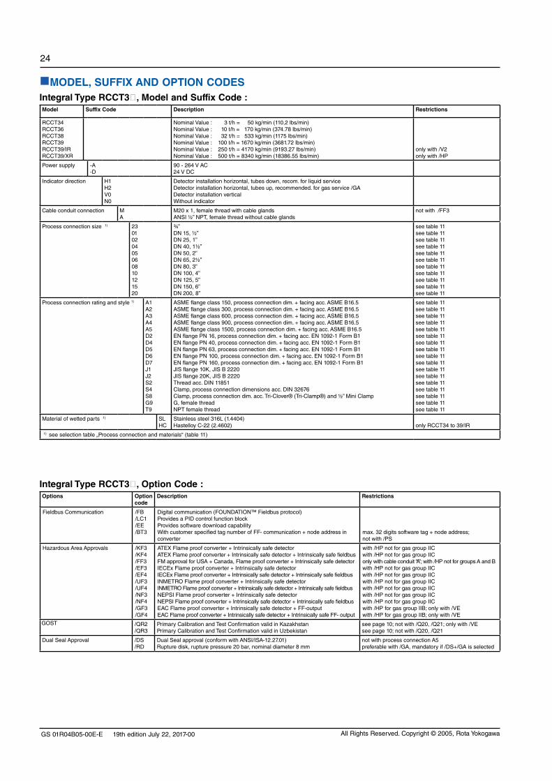
MODEL, SUFFIX AND OPTION CODESIntegral Type RCCT3, Model and Suffix Code :Model Suffix Code Description Restrictions
RCCT34RCCT36RCCT38RCCT39RCCT39/IRRCCT39/XR
Nominal Value : 3 t/h = 50 kg/min (110,2 lbs/min)Nominal Value : 10 t/h = 170 kg/min (374.78 lbs/min) Nominal Value : 32 t/h = 533 kg/min (1175 lbs/min)Nominal Value : 100 t/h = 1670 kg/min (3681.72 lbs/min)Nominal Value : 250 t/h = 4170 kg/min (9193.27 lbs/min)Nominal Value : 500 t/h = 8340 kg/min (18386.55 lbs/min)
only with /V2only with /HP
Power supply -A-D
90 - 264 V AC24 V DC
Indicator direction H1H2V0N0
Detector installation horizontal, tubes down, recom. for liquid serviceDetector installation horizontal, tubes up, recommended. for gas service /GADetector installation verticalWithout indicator
Cable conduit connection MA
M20 x 1, female thread with cable glandsANSI ½” NPT, female thread without cable glands
not with /FF3
Process connection size 1) 2301020405060810121520
¾”DN 15, ½”DN 25, 1”DN 40, 1½”DN 50, 2”DN 65, 2½”DN 80, 3”DN 100, 4”DN 125, 5”DN 150, 6”DN 200, 8”
see table 11see table 11see table 11see table 11see table 11see table 11see table 11see table 11see table 11see table 11see table 11
Process connection rating and style 1) A1A2A3A4A5D2D4D5D6D7J1J2S2S4S8G9T9
ASME flange class 150, process connection dim. + facing acc. ASME B16.5ASME flange class 300, process connection dim. + facing acc. ASME B16.5ASME flange class 600, process connection dim. + facing acc. ASME B16.5ASME flange class 900, process connection dim. + facing acc. ASME B16.5ASME flange class 1500, process connection dim. + facing acc. ASME B16.5EN flange PN 16, process connection dim. + facing acc. EN 1092-1 Form B1EN flange PN 40, process connection dim. + facing acc. EN 1092-1 Form B1EN flange PN 63, process connection dim. + facing acc. EN 1092-1 Form B1EN flange PN 100, process connection dim. + facing acc. EN 1092-1 Form B1EN flange PN 160, process connection dim. + facing acc. EN 1092-1 Form B1JIS flange 10K, JIS B 2220JIS flange 20K, JIS B 2220Thread acc. DIN 11851Clamp, process connection dimensions acc. DIN 32676Clamp, process connection dim. acc. Tri-Clover® (Tri-Clamp®) and ½” Mini ClampG, female threadNPT female thread
see table 11see table 11see table 11see table 11see table 11see table 11see table 11see table 11see table 11see table 11see table 11see table 11see table 11see table 11see table 11see table 11see table 11
Material of wetted parts 1) SLHC
Stainless steel 316L (1.4404)Hastelloy C-22 (2.4602) only RCCT34 to 39/IR
1) see selection table „Process connection and materials“ (table 11)
Integral Type RCCT3, Option Code :Options Option
codeDescription Restrictions
Fieldbus Communication /FB /LC1 /EE /BT3
Digital communication (FOUNDATION™ Fieldbus protocol)Provides a PID control function block Provides software download capability With customer specified tag number of FF- communication + node address in converter
max. 32 digits software tag + node address;not with /PS
Hazardous Area Approvals /KF3 /KF4 /FF3 /EF3 /EF4 /UF3 /UF4 /NF3/NF4/GF3/GF4
ATEX Flame proof converter + Intrinsically safe detector ATEX Flame proof converter + Intrinsically safe detector + Intrinsically safe fieldbus FM approval for USA + Canada, Flame proof converter + Intrinsically safe detector IECEx Flame proof converter + Intrinsically safe detector IECEx Flame proof converter + Intrinsically safe detector + Intrinsically safe fieldbus INMETRO Flame proof converter + Intrinsically safe detector INMETRO Flame proof converter + Intrinsically safe detector + Intrinsically safe fieldbusNEPSI Flame proof converter + Intrinsically safe detector NEPSI Flame proof converter + Intrinsically safe detector + Intrinsically safe fieldbus EAC Flame proof converter + Intrinsically safe detector + FF-outputEAC Flame proof converter + Intrinsically safe detector + Intrinsically safe FF- output
with /HP not for gas group IICwith /HP not for gas group IIC only with cable conduit “A”; with /HP not for groups A and B with /HP not for gas group IIC with /HP not for gas group IIC with /HP not for gas group IIC with /HP not for gas group IIC with /HP not for gas group IIC with /HP not for gas group IICwith /HP for gas group IIB; only with /VEwith /HP for gas group IIB; only with /VE
GOST /QR2/QR3
Primary Calibration and Test Confirmation valid in Kazakhstan Primary Calibration and Test Confirmation valid in Uzbekistan
see page 10; not with /Q20, /Q21; only with /VEsee page 10; not with /Q20, /Q21
Dual Seal Approval /DS/RD
Dual Seal approval (conform with ANSI/ISA-12.27.01)Rupture disk, rupture pressure 20 bar, nominal diameter 8 mm
not with process connection A5preferable with /GA, mandatory if /DS+/GA is selected

GS 01R04B05-00E-E 19th edition July 22, 2017-00
25
All Rights Reserved. Copyright © 2005, Rota Yokogawa
Integral Type RCCT3, Option Code (continued) :Options Option
codeDescription Restrictions
High Driving Power /HP High Driving Power; recommended for RCCT36 to 39, strongly recommended for RCCT39/IR 1) , Please see „ Hazardous Area Specifications“
mandatory for RCCT39/XR
Tag Number /BG With customer specified tag number on name plate max. 16 digits; numbers 0 to 9, latin alphabet, characters: +,- ,* , / and space
Flange Facing /DN /EN/FN /RJ
Flange with safety grooves acc. to EN 1092-1 form DFlange with spigot acc. to EN 1092-1 form EFlange with recess acc. to EN 1092-1 form FRing Type Joint Flanges
only for D2 to D6; not HConly for D2 to D6; not HConly for D2 to D6; not HConly for A3, A4, A5; not HC
Gas Measurement /GA Gas measurement, special factory adjustments and settings to be conform with ANSI/ISA-12.27.01 select /RD; not with /Q20
Special Calibration /K2 2)
/K4 /K5 2)
/K6
Custom 5 pts mass-/volume-flow calibration using water with factory certificate (traceable to German national standards)Density adjustment + thermal treatment; (accuracy: 0.001 g/cm³) Custom 10 pts mass-/volume-flow calibration using water with DAkkS certificate (according EN-17025:2005)Density calibration with 3 different fluids incl. individual temperature compensation with certificate (accuracy: 0.0005 g/cm³)
only RCCT34 to 39; not with /GA
only RCCT34 to 39; not with /GA
Certificates /P2/P3/P6/P8/H1/WP
/L2
/L3/L4
Certificate of compliance with the order acc. to EN 10204:2004 -2.1Test Report acc. to EN10204:2004-2.2(QIC) including the content of option /P2Material certificate acc. to EN 10204: 2004 -3.1Pressure test report measuring systemOil and fat free for wetted surface acc. to ASTM G93-03 level CWPS acc. DIN EN ISO 15609-1 (Welding Procedure Specification)WPQR acc. DIN EN ISO 15614-1 (Welding Procedure Qualification Record)WQC acc. DIN EN 287-1 (Welder Qualification Certificate)Calibration certificate level 2: Declaration and the Calibration Equipment List are issued Calibration certificate level 3: Declaration and the Primary Standard List are issued Calibration certificate level 4: Declaration and the Yokogawa Measuring Instruments Control System are issued
only for butt weld between process connection and flow divider
Sanitary Type /SF1
/SF2/SA/SE
Surface roughness Ra = 0.8 µm
As /SF1 + Test report roughness of wetted partsAs /SF2 + 3A- declaration of conformity and 3A- markAs /SF2 + EHEDG certificate
only RCCT34 to 39; not with RCCT34 /K4 and RCCT34 / K6; only process connections S2, S4, S8;as /SF1as /SF1, but not with process connection S2as /SF1, but not with process connection S2
Customer Presetting /PS Presetting sheet with customer data has to be issued with the order; not with /BT3
Housing Pressure Test /J1 Rupture pressure proof test and certificate (see page 4) not for RCCT39/XR
X-Ray Examination /RT X-ray examination of flange welding RCCT34 with /K4 or /K6 only one-sided; not with HC
PMI Certificate /PM6 PMI Test on wetted parts
Dye Penetrant Test /PT Dye Penetrant Test acc. DIN EN ISO 3452-1 at the weldings of the process connection, with certificate
Epoxy Coating /X1 Epoxy coating of converter housing
Concentration Measurement 3) /CST/C
Standard concentration measurementAdvanced concentration measurement, details see table „Advanced Concentration Measurement Options“
not with /GA, /Cnot with /GA, /CST
Version IR /V2 Version 2 always with RCCT39/IR
Delivery to Korea /KC With KC-mark for Korea
Eurasian Conformity /VE With EAC- mark combination with Hazardous Area Approval only with /GFDelivery to China /CN For delivery to China combination with Hazardous Area Approval only with /NFCable glands /AD2 2 pcs ANSI 1/2“ NPT / G1/2 adapter only with cable conduit “A”
Instruction Manuals /IE/ID/IF
Quantity of instruction manuals in EnglishQuantity of instruction manuals in GermanQuantity of instruction manuals in French
= 1 to 3 selectable 4)
= 1 to 3 selectable 4)
= 1 to 3 selectable 4)
Special order /Z Special design, must be specified separately.If /Z is selected, several Suffix of Model-Suffix Code can be changed to Z.
1) For gas application /GA RCCT39/XR can also be ordered without /HP.2) Calibration order sheet must be delivered with the order. This is available on the Flow Center Page at Coriolis/RCC3/Technical Information. Volume calibration: Mass flow calibration converted by density to volume flow.3) Measuring tube PAMI test is performed per delivery batch.3) For detailed information please see TI 01R04B04-04E-E. Concentration measurement is recommended with option /K6.4) If no instruction manual is selected, only a DVD with instruction manuals is shipped with the instrument. More than 3 manuals of one language on request.

GS 01R04B05-00E-E 19th edition July 22, 2017-00
26
All Rights Reserved. Copyright © 2005, Rota Yokogawa
Remote Detector RCCS3, Model and Suffix Code :Model Suffix Code Description Restrictions
RCCS30LRRCCS30RCCS31RCCS32RCCS33RCCS34RCCS36RCCS38RCCS39RCCS39/IRRCCS39/XR
Nominal Value : 0.021 t/h = 0.35 kg/min (0.77 lbs/min)Nominal Value : 0.045 t/h = 0.75 kg/min (1.65 lbs/min)Nominal Value : 0.17 t/h = 2.8 kg/min (6.17 lbs/min)Nominal Value : 0.37 t/h = 6.2 kg/min (13.66 lbs/min)Nominal Value : 0.95 t/h = 16 kg/min (35.27 lbs/min)Nominal Value : 3 t/h = 50 kg/min (110,2 lbs/min)Nominal Value : 10 t/h = 170 kg/min (374.78 lbs/min) Nominal Value : 32 t/h = 533 kg/min (1175 lbs/min)Nominal Value : 100 t/h = 1670 kg/min (3681.72 lbs/min)Nominal Value : 250 t/h = 4170 kg/min (9193.27 lbs/min)Nominal Value : 500 t/h = 8340 kg/min (18386.55 lbs/min)
only with /V2select affiliated RCCF31 with /HP
Cable conduit connection -M-A
M20 x 1, female thread with cable glandsANSI ½” NPT, female thread only with cable gland for detector connection
not with /FS1
Process connection size 1) 410123020405060810121520
¼”DN 15, ½” ¾”DN 25, 1”DN 40, 1½”DN 50, 2”DN 65, 2½”DN 80, 3”DN 100, 4”DN 125, 5”DN 150, 6”DN 200, 8”
see table 11see table 11see table 11see table 11see table 11see table 11see table 11see table 11see table 11see table 11see table 11see table 11
Process connection rating and style 1) A1A2A3A4A5D2D4D5D6D7J1J2S2S4S8G9T9
ASME flange class 150, process connection dim. + facing acc. ASME B16.5ASME flange class 300, process connection dim. + facing acc. ASME B16.5ASME flange class 600, process connection dim. + facing acc. ASME B16.5ASME flange class 900, process connection dim. + facing acc. ASME B16.5ASME flange class 1500, process connection dim. + facing acc. ASME B16.5EN flange PN 16, process connection dim. + facing acc. EN 1092-1 Form B1EN flange PN 40, process connection dim. + facing acc. EN 1092-1 Form B1EN flange PN 63, process connection dim. + facing acc. EN 1092-1 Form B1EN flange PN 100, process connection dim. + facing acc. EN 1092-1 Form B1EN flange PN 160, process connection dim. + facing acc. EN 1092-1 Form B1JIS flange 10K, JIS B 2220JIS flange 20K, JIS B 2220Thread acc. DIN 11851Clamp, process connection dimensions acc. DIN 32676Clamp, process connection dim. acc. Tri-Clover® (Tri-Clamp®) and ½” Mini ClampG female threadNPT female thread
see table 11see table 11see table 11see table 11see table 11see table 11see table 11see table 11see table 11see table 11see table 11see table 11see table 11see table 11see table 11see table 11see table 11
Material of wetted parts 1) SHSLHC
316L (1.4404) and Hastelloy C-22 (2.4602) for tubeStainless steel 316L (1.4404)Hastelloy C-22 (2.4602)
only RCCS30LR to 33only RCCS34 to 39/XRonly RCCS34 to 39/IR
1) see selection table „Process connection and materials“ (table 11)

GS 01R04B05-00E-E 19th edition July 22, 2017-00
27
All Rights Reserved. Copyright © 2005, Rota Yokogawa
Remote Detector RCCS3, Option Code :Options Option
codeDescription Restrictions
Hazardous Area Approvals 1) /KS1/FS1/ES1/US1/NS1/GS1
ATEX intrinsicallyally safe approvalFM intrinsicallyally safe approval for USA + CanadaIECEx intrinsicallyally safe approvalINMETRO intrinsicallyally safe approval for BrazilNEPSI intrinsicallyally safe approval for ChinaEAC intrinsicallyally safe approval
only with cable conduit “A”
only with /VE
GOST 1) /QR2/QR3
Primary Calibration and Test Confirmation valid in Kazakhstan Primary Calibration and Test Confirmation valid in Uzbekistan
see page 10; not with /Q20, /Q21; only with /VEsee page 10; not with /Q20, /Q21
Dual Seal Approval /DS/RD
Dual Seal approval (conform with ANSI/ISA-12.27.01)Rupture disk, rupture pressure 20 bar, nominal diameter 8 mm
only RCCS34 to 39/XR; not with process connection A5only RCCS34 to 39/XR, preferable with /GA, not with /T1, /T2, /T3, mandatory if /DS + /GA is selected
Tag Number /BG With customer specified tag number on name plate max. 16 digits
Flange Facing /DN
/EN
/FN
/RJ
Flange with safety grooves acc. to EN 1092-1 form D
Flange with spigot acc. to EN 1092-1 form E
Flange with recess acc. to EN 1092-1 form F
Ring Type Joint Flanges
only for D2 to D6; not HC, for RCCS30LR only for 01D4 or 01D6only for D2 to D6; not HC, for RCCS30LR only for 01D4 or 01D6only for D2 to D6; not HC, for RCCS30LR only for 01D4 or 01D6only for A3, A4, A5; not HC, for RCCS30LR only for 01A3 or 01A5
Gas Measurement /GA Gas measurement, special factory adjustments and settings select affiliated RCCF31 with /GA;to be conform with ANSI/ISA-12.27.01 select /RD; not with /Q20
Low temperature version /LT -200°C ≤ Tmedium ≤ 150°C (-328°F to 302°F) for RCCS34 to 39/XR; not with /MT, /HT, /Q01, /T1, /T2, /T3 ;in combination with Hazardous Area Approval only with /S2
Extended temperature range /MT -70°C ≤ Tmedium ≤ 230°C (-94°F to 446°F)-50°C ≤ Tmedium ≤ 260°C (-58°F to 500°F)
for RCCS34 to 39/XR; always with /S2 or /T1, /T2, /T3 ; for RCCS30LR to 33, always with /S2 or /T1, /T2, /T3
High temperature version /HT Tmedium up to 350°C (662°F) RCCS34 to 39/XR; only with/T1, /T2, /T3 or /S2 (cus-tomer insulation required); RCCS39/XR only with /S2;
Special Calibration /K2 3)
/K4 /K5 3)
/K6
Custom 5 pts mass-/volume-flow calibration using water with factory certificate (traceable to German national standards)Density adjustment + thermal treatment; (accuracy: 0.001 g/cm³) Custom 10 pts mass-/volume-flow calibration using water with DAkkS certificate (according EN-17025:2005)Density calibration with 3 different fluids incl. individual temperature compensation with certificate (accuracy: 0.0005 g/cm³)
only in combination with converter RCCF31
only RCCS31 to 39; not with /GAonly in combination with converter RCCF31
only RCCS32 to 39; not with /GA; not with /LT; not with /MT; only available if converter is also ordered
Certificates /P2/P3/P6/P8/H1/WP
/L2
/L3/L4
Certificate of compliance with the order acc. to EN 10204:2004 -2.1Test Report acc. to EN10204:2004-2.2(QIC) including the content of option /P2 Material certificate acc to EN 10204: 2004 -3.1Pressure test report measuring systemOil and fat free for wetted surface acc. to ASTM G93-03 level CWPS acc. DIN EN ISO 15609-1 (Welding Procedure Specification)WPQR acc. DIN EN ISO 15614-1 (Welding Procedure Qualification Record)WQC acc. DIN EN 287-1 (Welder Qualification Certificate)Calibration certificate level 2: Declaration and the Calibration Equipment List are issued Calibration certificate level 3: Declaration and the Primary Standard List are issued Calibration certificate level 4: Declaration and the Yokogawa Measuring Instruments Control System are issued
only for butt weld between process connection and flow divider
Sanitary Type /SF1
/SF2/SA/SE
Surface roughness Ra = 0.8 µm
As /SF1 + Test report roughness of wetted partsAs /SF2 + 3A- declaration of conformity and 3A- markAs /SF2 + EHEDG- certificate
only RCCS34 to 39; not with RCCS34 /K4, RCCS34 / K6 and RCCS34 /LT ; only process connections S2, S4, S8as /SF1as /SF1, but not with process connection S2as /SF1, but not with process connection S2
Mounting set /PD 2 inch pipe mounting set, recommended for RCCS30LR and RCCS30 only RCCS30LR to 33; not with /THousing Pressure Test /J1 Rupture pressure proof test and certificate (see page 4) not for RCCS30LR to 33 + RCCS39/XR
Customer insulation / Heating /S2 Terminal box on extension for high or low process temperature not with /T1, /T2, /T3
Factory Insulating / Heating /T1/T2/T3
InsulationInsulation + Heat carrier heatingInsulation + Heat carrier heating with ventilation (purge)
not for RCCS39/XRnot for RCCS39/XRnot for RCCS39/XR
X-Ray Examination /RT X-ray examination of flange welding RCCS30LR to 33 and RCCS34 with /K4, /K6 or /LT only one-sided; not with HC
PMI Certificate /PM4/PM6
PMI Test on wetted parts RCCS30LR to 33 4)
PMI Test on wetted parts RCCS34 to 39/XR not RCCS34 to 39/XRnot RCCS30LR to 33
Dye Penetrant Test /PT Dye Penetrant Test acc. DIN EN ISO 3452-1 at the weldings of the process connection, with certificate
Stainless steel cable gland /BS Cable gland stainless steel
Version IR /V2 Version 2 always with RCCS39/IR
Delivery to Korea /KC With KC-mark for Korea
Eurasian Conformity /VE With EAC- mark combination with Hazardous Area Approval only with /GS1Delivery to China /CN For meters which are delivered to China combination with Hazardous Area Approval only with /NS1Special order /Z Special design, must be specified separately.
If /Z is selected, several Suffix of Model-Suffix Code can be changed to Z.1) Select affiliated converter RCCF31 with the same approval type (e.g. ATEX).2) Calibration order sheet must be delivered with the order. This is available on the Flow Center Page at Coriolis/RCC3/Technical Information. Volume calibration: Mass flow calibration converted by density to volume flow.
3) Measuring tube PMI test is performed per delivery batch.

GS 01R04B05-00E-E 19th edition July 22, 2017-00
28
All Rights Reserved. Copyright © 2005, Rota Yokogawa
Remote field-mount Converter RCCF31, Model, Suffix and Option Code :Model Suffix Code Option
CodeDescription Restrictions
RCCF31 Remote field-mount converter to be connected to RCCS3;when ordered without detector combination option /NC must be selected
Power supply -A-D
90 - 264 V AC24 V DC
Indicator direction H2N0
With indicatorWithout indicator
Cable conduit connection MA
M20 x 1, female thread with cable glandsANSI ½” NPT, female thread, only cable gland for detector connection
not with /FF3
Fieldbus Communication /FB /LC1 /EE /BT3
Digital communication (Foundation™ Fieldbus protocol) Provides a PID control function block Provides software download capability With customer specified tag number of FF- communication + node address in converter
only with /LR or /SR
max. 32 digits software tag + node address ;not with /PS
Hazardous Area Approvals 1) /KF3 /KF4 /FF3 /EF3 /EF4 /UF3 /UF4/NF3/NF4/GF3/GF4
ATEX Flame proof converter + Intrinsically safe detector outputATEX Flame proof converter + Intrinsically safe detector + Intrinsically safe fieldbus FM approval for USA+Canada, Flame proof converter + Intrinsically safe detector IECEx Flame proof converter + Intrinsically safe detector IECEx Flame proof converter + Intrinsically safe detector + Intrinsically safe fieldbusINMETRO Flame proof converter + Intrinsically safe detector INMETRO Flame proof converter + Intrinsically safe detector + Intrinsically safe fieldbusNEPSI Flame proof converter + Intrinsically safe detector outputNEPSI Flame proof converter + Intrinsically safe detector + Intrinsically safe fieldbusEAC Flame proof converter + Intrinsically safe detector output + FF outputEAC Flame proof converter + Intrinsically safe detector output + Intrinsically safe FF- output
with /HP for gas group IIB with /HP for gas group IIB only with cable conduit “A”; with /HP not for groups A and B with /HP for gas group IIB with /HP for gas group IIB with /HP for gas group IIB with /HP for gas group IIB with /HP for gas group IIB with /HP for gas group IIB with /HP for gas group IIB, only with /VEwith /HP for gas group IIB, only with /VE
GOST 1) /QR2/QR3
Primary Calibration and Test Confirmation valid in Kazakhstan Primary Calibration and Test Confirmation valid in Uzbekistan
see page 10; not with /Q20, /Q21; only with /VEsee page 10; not with /Q20, /Q21
High Driving Power /HP High Driving Power, recommended for combination with RCCS36 to 39, strongly recommended for combination with RCCS39/IR, Please see „ Hazardous Area Specifications“
mandatory for combination with RCCS39/XR
Combined detector /LR/SR
In combination with RCCS30LRIn combination with RCCS30...RCCS39XR
Tag Number /BG With customer specified tag number on name plate max. 16 digits; numbers 0 to 9, latin alphabet, characters: +,- ,* , / and space
Gas Measurement /GA Gas measurement, special factory adjustments and settings select affiliated RCCS3 with /GA
Combination with RCCS39/XR /XR Combination with RCCS39/XR mandatory for combination with RCCS39/XR
No Combination /NC No combination with detector
Customer Presetting /PS Presetting sheet with customer data has to be issued with the order; not with /BT3
Epoxy Coating /X1 Epoxy coating of converter housing
Cable glands /AD2 2 pcs ANSI 1/2“ NPT / G1/2 adapter only with cable conduit “A”
Concentration Measurement 2) /CST/C
Standard concentration measurementAdvanced concentration measurement, details see table „Advanced Concentration Measurement Options“
not with /GA, /Cnot with /GA, /CST
Delivery to Korea /KC With KC-mark for Korea
Eurasian Conformity /VE With EAC- mark combination with Hazardous Area Approval only with /GFDelivery to China /CN For delivery to China combination with Hazardous Area Approval only with /NFCertificates /P2
/P3Certificate of compliance with the order acc. to EN 10204:2004 -2.1Test Report acc. to EN10204:2004-2.2(QIC) including the content of option /P2
Instruction Manuals /IE/ID/IF
Quantity of instruction manuals in EnglishQuantity of instruction manuals in GermanQuantity of instruction manuals in French
= 1 to 3 selectable 5)
= 1 to 3 selectable 5)
= 1 to 3 selectable 5)
Special order /Z Special design, must be specified separately.If /Z is selected, several Suffix of Model-Suffix Code can be changed to Z.
1) Select affiliated RCCS3 with the same approval type (e.g. /KF with /KS1).2) For detailed information please see TI 01R04B04-04E-E. Option /K6 of RCCS3 is recommended with concentration measurement. 3) If no instruction manual is selected, only a DVD with instruction manuals is shipped with the instrument. More than 3 manuals of one language on request.4) RCCF31 in combination with RCCS39/XR with gas application /GA can also be ordered without /HP.

GS 01R04B05-00E-E 19th edition July 22, 2017-00
29
All Rights Reserved. Copyright © 2005, Rota Yokogawa
Remote Cable RCCY03 to connect RCCF31/CR31 with RCCS3 Model, Suffix and Option Code :Model Suffix Code Option
CodeDescription Restrictions
RCCY031RCCY032RCCY033RCCY034
Length in “meter”Length in “feet”Length in “meter”Length in “feet”
max. ambient temperature 70°C (158°F); with /FFx or /FS1: 50°C (122°F)max. ambient temperature 70°C (158°F); with /FFx or /FS1: 50°C (122°F)max. ambient temperature 105°C (221°F); with /FFx or /FS1: 85°C (185°F)max. ambient temperature 105°C (221°F); with /FFx or /FS1: 85°C (185°F)
Cable ends -0-1
No termination, with one termination kitTerminated
Cable length L Enter the length max. 300m / 999ftthe following lengths can be ordered (e.g. 3m = L003):RCCY031-0: 3m, 5m, 10m, 15m, 30m, 50m, 100m, 150m, 200m, 250m, 300mRCCY031-1: 3m, 5m, 10m, 15m, 30m, 50mRCCY032-0: 10ft, 15ft, 30ft, 50ft, 100ft, 150ft, 300ft, 500ft, 1000ftRCCY032-1: 10ft, 15ft, 30ft, 50ft, 100ft, 150ftRCCY033-0: 3m, 5m, 10m, 15m, 30m, 50m, 100m, 150m, 300mRCCY033-1: 3m, 5m, 10m, 15m, 30m, 50mRCCY034-0: 10ft, 15ft, 30ft, 50ft, 100ft, 150ft, 300ft, 500ft, 1000ftRCCY034-1: 10ft, 15ft, 30ft, 50ft, 100ft, 150ft
Options:Hazardous area installation
Termination kitsDelivery to ChinaQuick delivery
/KS1/NS1/TK/CN/QD
Blue cable for Ex-i indicationBlue cable for Ex-i indication (China)Quantity of additional termination kitsFor meters which are delivered to ChinaDelivery within 24 hours from factory
only with /CN = 01 to 99combination with Hazardous Area Approval only with /NS1only L003, L005, L010
Advanced Concentration Measurement Options (others on request), recommended with Option /K6:Option Display Components Concentration
rangeTemp. range Source of concentration- / density table
/C00 --- --- --- --- Advanced concentration measurement function.There are no pre-defined concentration setups (coefficients are set to zero). The concentration coefficients will be set by customer making use of either FieldMate or the stand- alone concentration tool and manual entry by HHT. For more information, please contact your regional Yokogawa office.
/C01 °Brix Sugar / Water 0 - 85 °Brix 0 - 80°C(32 - 176°F)
PTB- Messages 100 5/90:„The density of watery Saccarose solutions after the introduction of the international tempera-ture scale of 1990 (ITS1990)“ Table 5
/C02 WT% NaOH / Water 2 - 50 WT% 0 - 100°C (32 - 212°F)
D´Ans-Lax, Handbook for chemists and physicists Vol.1, 3rd edition, 1967
/C03 WT% KOH / Water 0 - 60 WT% 54 - 100°C(129 - 212°F)
D´Ans-Lax, Handbook for chemists and physicists Vol.1, 3rd edition, 1967
/C04 WT% NH4NO3 / Water 1 - 50 WT% 0 - 80°C(32 - 176°F)
Data table on request
/C05 WT% NH4NO3 / Water 20 - 70 WT% 20 - 100°C (68 - 212°F)
Data table on request
/C06 1) WT% HCl / Water 22 - 34 WT% 20 - 40°C(68 - 104°F)
D´Ans-Lax, Handbook for chemists and physicists Vol.1, 3rd edition, 1967
/C07 WT% HNO3 / Water 50 - 67 WT% 10 - 60°C(50 - 140°F)
Data table on request
/C09 WT% H2O2 / Water 30 - 75 WT% 4 - 44°C(39.2 - 111.2°F)
Data table on request
/C10 WT% Ethylene Glycol / Water
10 - 50 WT% -20 - 40°C(-4 - 104°F)
Data table on request
/C11 WT% Amylum = starch / Water
33 - 43 WT% 35 - 45°C(95 - 113°F)
Data table on request
/C12 WT% Methanol / Water 35 - 60 WT% 0 - 40°C(32 - 104°F)
Data table on request
/C20 VOL% Alcohol / Water 55 - 100 VOL% 10 - 40°C(50 - 104°F)
Data table on request
/C21 °Brix Sugar / Water 40 - 80 °Brix 75 - 100°C(167 - 212°F)
Data table on request
/C30 WT% Alcohol / Water 66 - 100 WT% 15 - 40°C(59 - 104°F)
Standard Copersucar 1967
/C37 WT% Alcohol / Water 66 - 100 WT% 10 - 40°C(50 - 104°F)
Brazilian Standard ABNT
/C38 VOL% Alcohol / Water 73 - 100 VOL% 10 - 40°C(50 - 104°F)
Brazilian Standard ABNT
1) only with material HC
RELATED INSTRUMENTS
The customer should prepare instrument maintenance tool, terminator, fieldbus power supply etc.
Safety barrier for version with intrinsic safe FF-output (option /KF4, /EF4, /NF4, /GF4) See web page www.yokogawa.com/fbs/Interoperability/fbs-accessories-en.htm

GS 01R04B05-00E-E 19th edition July 22, 2017-00
30
All Rights Reserved. Copyright © 2005, Rota Yokogawa
Table 11 : Selection Table Process Connection and Materials, Installation Length in mmRCCS30LR
RCCS30-33
RCCS34RCCT34
RCCS36RCCT36
RCCS38RCCT38
RCCS39RCCT39
RCCS39/IRRCCT39/IR
RCCS39/XRRCCT39/XR
SH SH SL HC SL HC SL HC SL HC SL HC SL HC
Fla
ng
es a
cco
rdin
g to
AS
ME
B16
.5
01A1 ½“-150 240 240 370 ---- ---- ---- ---- ---- ---- ---- ---- ---- ---- ----
01A2 ½“-300 240 240 370 ---- ---- ---- ---- ---- ---- ---- ---- ---- ---- ----
01A3 ½“-600 250 250 380 ---- ---- ---- ---- ---- ---- ---- ---- ---- ---- ----
01A4 ½“-900 ---- ---- 400 ---- ---- ---- ---- ---- ---- ---- ---- ---- ---- ----
01A5 ½“-900/1500 270 270 400 ---- ---- ---- ---- ---- ---- ---- ---- ---- ---- ----
02A1 1“-150 ---- 240 370 390 500 ---- ---- ---- ---- ---- ---- ---- ---- ----
02A2 1“-300 ---- 240 370 390 500 ---- ---- ---- ---- ---- ---- ---- ---- ----
02A3 1“-600 ---- 260 390 390 520 ---- ---- ---- ---- ---- ---- ---- ---- ----
02A4 1“-900 ---- ---- 450 400 540 ---- ---- ---- ---- ---- ---- ---- ---- ----
02A5 1“-900/1500 ---- 320 450 400 540 ---- ---- ---- ---- ---- ---- ---- ---- ----
04A1 1½“-150 ---- 250 380 390 500 520 600 ---- ---- ---- ---- ---- ---- ----
04A2 1½“-300 ---- 250 380 390 510 520 600 ---- ---- ---- ---- ---- ---- ----
04A3 1½“-600 ---- 270 400 400 530 530 620 ---- ---- ---- ---- ---- ---- ----
04A4 1½“-900 ---- ---- 470 ---- 600 ---- 640 ---- ---- ---- ---- ---- ---- ----
04A5 1½“-900/1500 ---- 340 470 ---- 600 ---- ---- ---- ---- ---- ---- ---- ---- ----
05A1 2“-150 ---- ---- ---- 390 510 520 600 620 ---- ---- ---- ---- ---- ----
05A2 2“-300 ---- ---- ---- 390 510 520 600 620 ---- ---- ---- ---- ---- ----
05A3 2“-600 ---- ---- ---- 400 540 540 630 630 ---- ---- ---- ---- ---- ----
05A4 2“-900 ---- ---- ---- ---- 660 ---- 720 ---- ---- ---- ---- ---- ---- ----
05A5 2“-900/1500 ---- ---- ---- ---- 660 ---- ---- ---- ---- ---- ---- ---- ---- ----
06A1 2½“-150 ---- ---- ---- ---- ---- ---- 610 620 ---- ---- ---- ---- ---- ----
06A2 2½“-300 ---- ---- ---- ---- ---- ---- 610 620 ---- ---- ---- ---- ---- ----
06A3 2½“-600 ---- ---- ---- ---- ---- ---- 640 640 ---- ---- ---- ---- ---- ----
06A4 2½“-900 ---- ---- ---- ---- ---- ---- 760 ---- ---- ---- ---- ---- ---- ----
08A1 3“-150 ---- ---- ---- ---- ---- ---- 610 620 1000 1020 ---- ---- ---- ----
08A2 3“-300 ---- ---- ---- ---- ---- ---- 620 620 1000 1020 ---- ---- ---- ----
08A3 3“-600 ---- ---- ---- ---- ---- ---- 640 640 1000 1025 ---- ---- ---- ----
08A4 3“-900 ---- ---- ---- ---- ---- ---- 760 ---- ---- ---- ---- ---- ---- ----
10A1 4“-150 ---- ---- ---- ---- ---- ---- ---- ---- 1000 1020 1100 ---- ---- ----
10A2 4“-300 ---- ---- ---- ---- ---- ---- ---- ---- 1000 1020 1100 ---- ---- ----
10A3 4“-600 ---- ---- ---- ---- ---- ---- ---- ---- 1030 1030 1100 ---- ---- ----
12A1 5“-150 ---- ---- ---- ---- ---- ---- ---- ---- 1000 1020 1100 1100 ---- ----
12A2 5“-300 ---- ---- ---- ---- ---- ---- ---- ---- 1000 1020 1100 1100 ---- ----
12A3 5“-600 ---- ---- ---- ---- ---- ---- ---- ---- 1040 1040 1160 1110 ---- ----
15A1 6“-150 ---- ---- ---- ---- ---- ---- ---- ---- ---- ---- 1100 1100 1350 ----
15A2 6“-300 ---- ---- ---- ---- ---- ---- ---- ---- ---- ---- 1100 1100 1350 ----
15A3 6“-600 ---- ---- ---- ---- ---- ---- ---- ---- ---- ---- 1200 1120 1390 ----
20A1 8“-150 ---- ---- ---- ---- ---- ---- ---- ---- ---- ---- 1140 1100 1350 ----
20A2 8“-300 ---- ---- ---- ---- ---- ---- ---- ---- ---- ---- 1140 1100 1350 ----
20A3 8“-600 ---- ---- ---- ---- ---- ---- ---- ---- ---- ---- ---- ---- 1440 ----
Fla
ng
es a
cco
rdin
g to
EN
109
2-1
01D4 DN 15 PN 40 240 240 370 ---- ---- ---- ---- ---- ---- ---- ---- ---- ---- ----
01D6 DN 15 PN 100 250 250 380 ---- ---- ---- ---- ---- ---- ---- ---- ---- ---- ----
02D4 DN 25 PN 40 ---- 240 370 390 500 520 ---- ---- ---- ---- ---- ---- ---- ----
02D6 DN 25 PN 100 ---- 260 390 ---- 520 ---- ---- ---- ---- ---- ---- ---- ---- ----
04D4 DN 40 PN 40 ---- 240 370 390 500 520 600 ---- ---- ---- ---- ---- ---- ----
04D6 DN 40 PN 100 ---- 320 450 ---- 560 ---- 620 ---- ---- ---- ---- ---- ---- ----
05D4 DN 50 PN 40 ---- ---- ---- ---- 500 520 600 620 ---- ---- ---- ---- ---- ----
05D5 DN 50 PN 63 ---- ---- ---- ---- 520 ---- 620 ---- ---- ---- ---- ---- ---- ----
05D6 DN 50 PN 100 ---- ---- ---- ---- 590 ---- 660 ---- ---- ---- ---- ---- ---- ----
05D7 DN 50 PN 160 ---- ---- ---- ---- 590 ---- 660 ---- ---- ---- ---- ---- ---- ----
08D4 DN 80 PN 40 ---- ---- ---- ---- ---- ---- 610 620 1000 1020 ---- ---- ---- ----
08D5 DN 80 PN 63 ---- ---- ---- ---- ---- ---- 620 ---- 1000 ---- ---- ---- ---- ----08D6 DN 80 PN 100 ---- ---- ---- ---- ---- ---- 730 ---- 1000 ---- ---- ---- ---- ----10D2 DN 100 PN 16 ---- ---- ---- ---- ---- ---- ---- ---- 1000 ---- 1100 ---- ---- ----
10D4 DN 100 PN 40 ---- ---- ---- ---- ---- ---- ---- ---- 1000 1020 1100 ---- ---- ----
10D5 DN 100 PN 63 ---- ---- ---- ---- ---- ---- ---- ---- 1000 ---- 1100 ---- ---- ----
10D6 DN 100 PN 100 ---- ---- ---- ---- ---- ---- ---- ---- 1050 ---- 1100 ---- ---- ----
12D2 DN 125 PN 16 ---- ---- ---- ---- ---- ---- ---- ---- 1000 1020 1100 1100 ---- ----
12D4 DN 125 PN 40 ---- ---- ---- ---- ---- ---- ---- ---- 1000 1020 1100 1100 ---- ----
12D5 DN 125 PN 63 ---- ---- ---- ---- ---- ---- ---- ---- 1000 ---- 1100 1100 ---- ----
12D6 DN 125 PN 100 ---- ---- ---- ---- ---- ---- ---- ---- 1100 ---- 1140 1100 ---- ----
12D7 DN 125 PN 160 ---- ---- ---- ---- ---- ---- ---- ---- ---- ---- ---- 1100 ---- ----
15D2 DN 150 PN 16 ---- ---- ---- ---- ---- ---- ---- ---- ---- ---- 1100 1100 1350 ----
15D4 DN 150 PN 40 ---- ---- ---- ---- ---- ---- ---- ---- ---- ---- 1100 1100 1350 ----
15D5 DN 150 PN 63 ---- ---- ---- ---- ---- ---- ---- ---- ---- ---- 1140 ---- 1350 ----
15D6 DN 150 PN 100 ---- ---- ---- ---- ---- ---- ---- ---- ---- ---- 1180 ---- ---- ----
20D2 DN 200 PN 16 ---- ---- ---- ---- ---- ---- ---- ---- ---- ---- ---- ---- 1350 ----
20D4 DN 200 PN 40 ---- ---- ---- ---- ---- ---- ---- ---- ---- ---- ---- ---- 1350 ----
20D5 DN 200 PN 63 ---- ---- ---- ---- ---- ---- ---- ---- ---- ---- ---- ---- 1350 ----

GS 01R04B05-00E-E 19th edition July 22, 2017-00
31
All Rights Reserved. Copyright © 2005, Rota Yokogawa
Table 11 : Selection Table Process Connection and Materials, Installation Length in mm (continued)
RCCS30-33
RCCS34RCCT34
RCCS36RCCT36
RCCS38RCCT38
RCCS39RCCT39
RCCS39/IRRCCT39/IR
RCCS39/XRRCCT39/XR
SH SL HC SL HC SL HC SL HC SL HC SL HC
Fla
ng
es a
cco
rdin
g to
JIS
B 2
220
01J1 DN 15 10K ---- 240 370 ---- ---- ---- ---- ---- ---- ---- ---- ---- ---- ----01J2 DN 15 20K ---- 240 370 ---- ---- ---- ---- ---- ---- ---- ---- ---- ---- ----02J1 DN 25 10K ---- 240 370 390 500 ---- ---- ---- ---- ---- ---- ---- ---- ----02J2 DN 25 20K ---- 240 370 390 500 ---- ---- ---- ---- ---- ---- ---- ---- ----04J1 DN 40 10K ---- 240 370 390 500 520 600 ---- ---- ---- ---- ---- ---- ----04J2 DN 40 20K ---- 240 370 390 500 520 600 ---- ---- ---- ---- ---- ---- ----05J1 DN 50 10K ---- ---- ---- ---- 500 520 600 620 ---- ---- ---- ---- ---- ----05J2 DN 50 20K ---- ---- ---- ---- 500 520 600 620 ---- ---- ---- ---- ---- ----08J1 DN 80 10K ---- ---- ---- ---- ---- ---- 600 620 1000 1020 ---- ---- ---- ----08J2 DN 80 20K ---- ---- ---- ---- ---- ---- 610 620 1000 1020 ---- ---- ---- ----10J1 DN 100 10K ---- ---- ---- ---- ---- ---- ---- ---- 1000 1020 1100 ---- ---- ----10J2 DN 100 20K ---- ---- ---- ---- ---- ---- ---- ---- 1000 1020 1100 ---- ---- ----
12J1 DN 125 10K ---- ---- ---- ---- ---- ---- ---- ---- 1000 1020 1100 1100 ---- ----
12J2 DN 125 20K ---- ---- ---- ---- ---- ---- ---- ---- 1000 1020 1100 1100 ---- ----15J1 DN 150 10K ---- ---- ---- ---- ---- ---- ---- ---- ---- ---- 1100 1100 ---- ----15J2 DN 150 20K ---- ---- ---- ---- ---- ---- ---- ---- ---- ---- 1100 1100 ---- ----
Cla
mp
DIN
01S4 DN 15 ---- 240 ---- ---- ---- ---- ---- ---- ---- ---- ---- ---- ---- ----02S4 DN 25 ---- 240 370 ---- ---- ---- ---- ---- ---- ---- ---- ---- ---- ----04S4 DN 40 ---- 240 370 ---- 500 ---- ---- ---- ---- ---- ---- ---- ---- ----05S4 DN 50 ---- ---- ---- ---- 500 ---- 600 ---- ---- ---- ---- ---- ---- ----06S4 DN 65 ---- ---- ---- ---- ---- ---- 600 ---- ---- ---- ---- ---- ---- ----10S4 DN 100 ---- ---- ---- ---- ---- ---- ---- ---- 1000 ---- ---- ---- ---- ----
Tri-
Cla
mp
01S8 ½“ ---- 240 ---- ---- ---- ---- ---- ---- ---- ---- ---- ---- ---- ----02S8 1“ ---- 240 370 ---- ---- ---- ---- ---- ---- ---- ---- ---- ---- ----04S8 1½“ ---- 240 370 ---- 500 ---- ---- ---- ---- ---- ---- ---- ---- ----05S8 2“ ---- ---- ---- ---- 500 ---- 600 ---- ---- ---- ---- ---- ---- ----08S8 3“ ---- ---- ---- ---- ---- ---- 600 ---- ---- ---- ---- ---- ---- ----10S8 4“ ---- ---- ---- ---- ---- ---- ---- ---- 1000 ---- ---- ---- ---- ----
DIN
1185
1 02S2 DN 25 ---- 240 370 ---- ---- ---- ---- ---- ---- ---- ---- ---- ---- ----04S2 DN 40 ---- ---- ---- ---- 500 ---- ---- ---- ---- ---- ---- ---- ---- ----05S2 DN 50 ---- ---- ---- ---- ---- ---- 600 ---- ---- ---- ---- ---- ---- ----10S2 DN 100 ---- ---- ---- ---- ---- ---- ---- ---- 1000 ---- ---- ---- ---- ----
Th
read
41G9 G¼“ female ---- 260 ---- ---- ---- ---- ---- ---- ---- ---- ---- ---- ---- ----01G9 G½“ female ---- 260 390 ---- ---- ---- ---- ---- ---- ---- ---- ---- ---- ----23G9 G¾“ female ---- 260 390 ---- ---- ---- ---- ---- ---- ---- ---- ---- ---- ----41T9 NPT¼“ female ---- 260 ---- ---- ---- ---- ---- ---- ---- ---- ---- ---- ---- ----01T9 NPT½“ female ---- 260 390 ---- ---- ---- ---- ---- ---- ---- ---- ---- ---- ----23T9 NPT¾“ female ---- 260 390 ---- ---- ---- ---- ---- ---- ---- ---- ---- ---- ----

GS 01R04B05-00E-E 19th edition July 22, 2017-00
32
All Rights Reserved. Copyright © 2005, Rota Yokogawa
Table 11 : Selection Table Process Connection and Materials, Installation Length in inchRCCS30LR
RCCS30-33
RCCS34RCCT34
RCCS36RCCT36
RCCS38RCCT38
RCCS39RCCT39
RCCS39/IRRCCT39/IR
RCCS39/XRRCCT39/XR
SH SH SL HC SL HC SL HC SL HC SL HC SL HC
Fla
ng
es a
cco
rdin
g to
AS
ME
B16
.5
01A1 ½“-150 9.45 9.45 14.57 ---- ---- ---- ---- ---- ---- ---- ---- ---- ---- ----01A2 ½“-300 9.45 9.45 14.57 ---- ---- ---- ---- ---- ---- ---- ---- ---- ---- ----01A3 ½“-600 9.84 9.84 14.96 ---- ---- ---- ---- ---- ---- ---- ---- ---- ---- ----01A4 ½“-900 ---- ---- 15.75 ---- ---- ---- ---- ---- ---- ---- ---- ---- ---- ----
01A5 ½“-900/1500 10.63 10.63 15.75 ---- ---- ---- ---- ---- ---- ---- ---- ---- ---- ----02A1 1“-150 ---- 9.45 14.57 15.35 19.69 ---- ---- ---- ---- ---- ---- ---- ---- ----02A2 1“-300 ---- 9.45 14.57 15.35 19.69 ---- ---- ---- ---- ---- ---- ---- ---- ----02A3 1“-600 ---- 10.24 15.35 15.35 20.47 ---- ---- ---- ---- ---- ---- ---- ---- ----02A4 1“-900 ---- ---- 17.72 15.75 21.26 ---- ---- ---- ---- ---- ---- ---- ---- ----02A5 1“-900/1500 ---- 12.6 17.72 15.75 21.26 ---- ---- ---- ---- ---- ---- ---- ---- ----04A1 1½“-150 ---- 9.84 14.96 15.35 19.69 20.47 23.62 ---- ---- ---- ---- ---- ---- ----04A2 1½“-300 ---- 9.84 14.96 15.35 20.08 20.47 23.62 ---- ---- ---- ---- ---- ---- ----04A3 1½“-600 ---- 10.63 15.75 15.75 20.87 20.87 24.21 ---- ---- ---- ---- ---- ---- ----04A4 1½“-900 ---- ---- 18.5 ---- 23.62 ---- 25.2 ---- ---- ---- ---- ---- ---- ----04A5 1½“-900/1500 ---- 13.39 18.5 ---- 23.62 ---- ---- ---- ---- ---- ---- ---- ---- ----05A1 2“-150 ---- ---- ---- 15.35 20.08 20.47 23.62 24.21 ---- ---- ---- ---- ---- ----05A2 2“-300 ---- ---- ---- 15.35 20.08 20.47 23.62 24.21 ---- ---- ---- ---- ---- ----05A3 2“-600 ---- ---- ---- 15.75 21.26 21.26 24.8 24.8 ---- ---- ---- ---- ---- ----05A4 2“-900 ---- ---- ---- ---- 25.98 ---- 28.35 ---- ---- ---- ---- ---- ---- ----05A5 2“-900/1500 ---- ---- ---- ---- 25.98 ---- ---- ---- ---- ---- ---- ---- ---- ----06A1 2½“-150 ---- ---- ---- ---- ---- ---- 24.02 24.21 ---- ---- ---- ---- ---- ----06A2 2½“-300 ---- ---- ---- ---- ---- ---- 24.02 24.21 ---- ---- ---- ---- ---- ----06A3 2½“-600 ---- ---- ---- ---- ---- ---- 25.2 25.2 ---- ---- ---- ---- ---- ----06A4 2½“-900 ---- ---- ---- ---- ---- ---- 29.92 ---- ---- ---- ---- ---- ---- ----08A1 3“-150 ---- ---- ---- ---- ---- ---- 24.02 24.21 39.37 40.16 ---- ---- ---- ----08A2 3“-300 ---- ---- ---- ---- ---- ---- 24.21 24.21 39.37 40.16 ---- ---- ---- ----08A3 3“-600 ---- ---- ---- ---- ---- ---- 25.2 25.2 39.37 40.35 ---- ---- ---- ----08A4 3“-900 ---- ---- ---- ---- ---- ---- 29.92 ---- ---- ---- ---- ---- ---- ----10A1 4“-150 ---- ---- ---- ---- ---- ---- ---- ---- 39.37 40.16 43.31 ---- ---- ----10A2 4“-300 ---- ---- ---- ---- ---- ---- ---- ---- 39.37 40.16 43.31 ---- ---- ----10A3 4“-600 ---- ---- ---- ---- ---- ---- ---- ---- 40.55 40.55 43.31 ---- ---- ----12A1 5“-150 ---- ---- ---- ---- ---- ---- ---- ---- 39.37 40.16 43.31 43.31 ---- ----12A2 5“-300 ---- ---- ---- ---- ---- ---- ---- ---- 39.37 40.16 43.31 43.31 ---- ----12A3 5“-600 ---- ---- ---- ---- ---- ---- ---- ---- 40.94 40.94 45.67 43.31 ---- ----15A1 6“-150 ---- ---- ---- ---- ---- ---- ---- ---- ---- ---- 43.31 43.31 53.15 ----15A2 6“-300 ---- ---- ---- ---- ---- ---- ---- ---- ---- ---- 43.31 43.31 53.15 ----15A3 6“-600 ---- ---- ---- ---- ---- ---- ---- ---- ---- ---- 47.2 43.31 54.72 ----20A1 8“-150 ---- ---- ---- ---- ---- ---- ---- ---- ---- ---- 44.9 43.31 53.15 ----20A2 8“-300 ---- ---- ---- ---- ---- ---- ---- ---- ---- ---- 44.9 43.31 53.15 ----20A3 8“-600 ---- ---- ---- ---- ---- ---- ---- ---- ---- ---- ---- ---- 56.69 ----
Fla
ng
es a
cco
rdin
g to
EN
109
2-1
01D4 DN 15 PN 40 9.45 9.45 14.57 ---- ---- ---- ---- ---- ---- ---- ---- ---- ---- ----01D6 DN 15 PN 100 9.84 9.84 14.96 ---- ---- ---- ---- ---- ---- ---- ---- ---- ---- ----02D4 DN 25 PN 40 ---- 9.45 14.57 15.35 19.69 20.47 ---- ---- ---- ---- ---- ---- ---- ----02D6 DN 25 PN 100 ---- 10.24 15.35 ---- 20.47 ---- ---- ---- ---- ---- ---- ---- ---- ----04D4 DN 40 PN 40 ---- 9.45 14.57 15.35 19.69 20.47 23.62 ---- ---- ---- ---- ---- ---- ----04D6 DN 40 PN 100 ---- 12.6 17.72 ---- 22.05 ---- 24.41 ---- ---- ---- ---- ---- ---- ----05D4 DN 50 PN 40 ---- ---- ---- ---- 19.69 20.47 23.62 24.41 ---- ---- ---- ---- ---- ----05D5 DN 50 PN 63 ---- ---- ---- ---- 20.47 ---- 24.41 ---- ---- ---- ---- ---- ---- ----05D6 DN 50 PN 100 ---- ---- ---- ---- 23.23 ---- 25.98 ---- ---- ---- ---- ---- ---- ----05D7 DN 50 PN 160 ---- ---- ---- ---- 23.23 ---- 25.98 ---- ---- ---- ---- ---- ---- ----08D4 DN 80 PN 40 ---- ---- ---- ---- ---- ---- 24.02 24.41 39.37 40.16 ---- ---- ---- ----08D5 DN 80 PN 63 ---- ---- ---- ---- ---- ---- 24.41 ---- 39.37 ---- ---- ---- ---- ----08D6 DN 80 PN 100 ---- ---- ---- ---- ---- ---- 28.74 ---- 39.37 ---- ---- ---- ---- ----10D2 DN 100 PN 16 ---- ---- ---- ---- ---- ---- ---- ---- 39.37 ---- 43.31 ---- ---- ----10D4 DN 100 PN 40 ---- ---- ---- ---- ---- ---- ---- ---- 39.37 40.16 43.31 ---- ---- ----10D5 DN 100 PN 63 ---- ---- ---- ---- ---- ---- ---- ---- 39.37 ---- 43.31 ---- ---- ----10D6 DN 100 PN 100 ---- ---- ---- ---- ---- ---- ---- ---- 41.34 ---- 43.31 ---- ---- ----12D2 DN 125 PN 16 ---- ---- ---- ---- ---- ---- ---- ---- 39.37 40.16 43.31 43.31 ---- ----12D4 DN 125 PN 40 ---- ---- ---- ---- ---- ---- ---- ---- 39.37 40.16 43.31 43.31 ---- ----12D5 DN 125 PN 63 ---- ---- ---- ---- ---- ---- ---- ---- 39.37 ---- 43.31 43.31 ---- ----12D6 DN 125 PN 100 ---- ---- ---- ---- ---- ---- ---- ---- 43.31 ---- 44.88 43.31 ---- ----12D7 DN 125 PN 160 ---- ---- ---- ---- ---- ---- ---- ---- ---- ---- ---- 43.31 ---- ----15D2 DN 150 PN 16 ---- ---- ---- ---- ---- ---- ---- ---- ---- ---- 43.31 43.31 53.15 ----15D4 DN 150 PN 40 ---- ---- ---- ---- ---- ---- ---- ---- ---- ---- 43.31 43.31 53.15 ----15D5 DN 150 PN 63 ---- ---- ---- ---- ---- ---- ---- ---- ---- ---- 44.88 ---- 53.15 ----15D6 DN 150 PN 100 ---- ---- ---- ---- ---- ---- ---- ---- ---- ---- 46.46 ---- ---- ----20D2 DN 200 PN 16 ---- ---- ---- ---- ---- ---- ---- ---- ---- ---- ---- ---- 53.15 ----20D4 DN 200 PN 40 ---- ---- ---- ---- ---- ---- ---- ---- ---- ---- ---- ---- 53.15 ----20D5 DN 200 PN 63 ---- ---- ---- ---- ---- ---- ---- ---- ---- ---- ---- ---- 53.15 ----

GS 01R04B05-00E-E 19th edition July 22, 2017-00
33
All Rights Reserved. Copyright © 2005, Rota Yokogawa
Table 11 : Selection Table Process Connection and Materials, Installation Length in inch (continued)
RCCS30-33
RCCS34RCCT34
RCCS36RCCT36
RCCS38RCCT38
RCCS39RCCT39
RCCS39RCCT39/IR
RCCS39RCCT39/XR
SH SL HC SL HC SL HC SL HC SL HC SL HC
Fla
ng
es a
cco
rdin
g to
JIS
B 2
220
01J1 DN 15 10K ---- 9.45 14.57 ---- ---- ---- ---- ---- ---- ---- ---- ---- ---- ----01J2 DN 15 20K ---- 9.45 14.57 ---- ---- ---- ---- ---- ---- ---- ---- ---- ---- ----02J1 DN 25 10K ---- 9.45 14.57 15.35 19.69 ---- ---- ---- ---- ---- ---- ---- ---- ----02J2 DN 25 20K ---- 9.45 14.57 15.35 19.69 ---- ---- ---- ---- ---- ---- ---- ---- ----04J1 DN 40 10K ---- 9.45 14.57 15.35 19.69 20.47 23.62 ---- ---- ---- ---- ---- ---- ----04J2 DN 40 20K ---- 9.45 14.57 15.35 19.69 20.47 23.62 ---- ---- ---- ---- ---- ---- ----05J1 DN 50 10K ---- ---- ---- ---- 19.69 20.47 23.62 24.41 ---- ---- ---- ---- ---- ----05J2 DN 50 20K ---- ---- ---- ---- 19.69 20.47 23.62 24.41 ---- ---- ---- ---- ---- ----08J1 DN 80 10K ---- ---- ---- ---- ---- ---- 23.62 24.41 39.37 40.16 ---- ---- ---- ----08J2 DN 80 20K ---- ---- ---- ---- ---- ---- 24.02 24.41 39.37 40.16 ---- ---- ---- ----
10J1 DN 100 10K ---- ---- ---- ---- ---- ---- ---- ---- 39.37 40.16 43.31 ---- ---- ----10J2 DN 100 20K ---- ---- ---- ---- ---- ---- ---- ---- 39.37 40.16 43.31 ---- ---- ----12J1 DN 125 10K ---- ---- ---- ---- ---- ---- ---- ---- 39.37 40.16 43.31 43.31 ---- ----
12J2 DN 125 20K ---- ---- ---- ---- ---- ---- ---- ---- 39.37 40.16 43.31 43.31 ---- ----15J1 DN 150 10K ---- ---- ---- ---- ---- ---- ---- ---- ---- ---- 43.31 43.31 ---- ----15J2 DN 150 20K ---- ---- ---- ---- ---- ---- ---- ---- ---- ---- 43.31 43.31 ---- ----
Cla
mp
DIN
01S4 DN 15 ---- 9.45 ---- ---- ---- ---- ---- ---- ---- ---- ---- ---- ---- ----02S4 DN 25 ---- 9.45 14.57 ---- ---- ---- ---- ---- ---- ---- ---- ---- ---- ----
04S4 DN 40 ---- 9.45 14.57 ---- 19.69 ---- ---- ---- ---- ---- ---- ---- ---- ----
05S4 DN 50 ---- ---- ---- ---- 19.69 ---- 23.62 ---- ---- ---- ---- ---- ---- ----06S4 DN 65 ---- ---- ---- ---- ---- ---- 23.62 ---- ---- ---- ---- ---- ---- ----10S4 DN 100 ---- ---- ---- ---- ---- ---- ---- ---- 39.37 ---- ---- ---- ---- ----
Tri-
Cla
mp
01S8 ½“ ---- 9.45 ---- ---- ---- ---- ---- ---- ---- ---- ---- ---- ---- ----02S8 1“ ---- 9.45 14.57 ---- ---- ---- ---- ---- ---- ---- ---- ---- ---- ----04S8 1½“ ---- 9.45 14.57 ---- 19.69 ---- ---- ---- ---- ---- ---- ---- ---- ----05S8 2“ ---- ---- ---- ---- 19.69 ---- 23.62 ---- ---- ---- ---- ---- ---- ----08S8 3“ ---- ---- ---- ---- ---- ---- 23.62 ---- ---- ---- ---- ---- ---- ----10S8 4“ ---- ---- ---- ---- ---- ---- ---- ---- 39.37 ---- ---- ---- ---- ----
DIN
1185
1 02S2 DN 25 ---- 9.45 14.57 ---- ---- ---- ---- ---- ---- ---- ---- ---- ---- ----04S2 DN 40 ---- ---- ---- ---- 19.69 ---- ---- ---- ---- ---- ---- ---- ---- ----05S2 DN 50 ---- ---- ---- ---- ---- ---- 23.62 ---- ---- ---- ---- ---- ---- ----10S2 DN 100 ---- ---- ---- ---- ---- ---- ---- ---- 39.37 ---- ---- ---- ---- ----
Th
read
41G9 G¼“ female ---- 10.24 ---- ---- ---- ---- ---- ---- ---- ---- ---- ---- ---- ----01G9 G½“ female ---- 10.24 15.35 ---- ---- ---- ---- ---- ---- ---- ---- ---- ---- ----23G9 G¾“ female ---- 10.24 15.35 ---- ---- ---- ---- ---- ---- ---- ---- ---- ---- ----41T9 NPT¼“ female ---- 10.24 ---- ---- ---- ---- ---- ---- ---- ---- ---- ---- ---- ----01T9 NPT½“ female ---- 10.24 15.35 ---- ---- ---- ---- ---- ---- ---- ---- ---- ---- ----23T9 NPT¾“ female ---- 10.24 15.35 ---- ---- ---- ---- ---- ---- ---- ---- ---- ---- ----

GS 01R04B05-00E-E 19th edition July 22, 2017-00
34
All Rights Reserved. Copyright © 2005, Rota Yokogawa
Table 12 : CRN approved process connections
RCCS30 - 32
RCCS34RCCT34
RCCS36RCCT36
RCCS38RCCT38
RCCS39RCCT39
RCCS39/IRRCCT39/IR
RCCS39/XRRCCT39/XR
SH SL HC SL HC SL HC SL HC SL HC SL
Fla
ng
es a
cco
rdin
g to
AS
ME
B16
.5
01A1 ½“-150 X X ---- ---- ---- ---- ---- ---- ---- ---- ---- ----01A2 ½“-300 X X ---- ---- ---- ---- ---- ---- ---- ---- ---- ----01A3 ½“-600 X X ---- ---- ---- ---- ---- ---- ---- ---- ---- ----01A5 ½“-900/1500 X X ---- ---- ---- ---- ---- ---- ---- ---- ---- ----02A1 1“-150 X X X X ---- ---- ---- ---- ---- ---- ---- ----02A2 1“-300 X X X X ---- ---- ---- ---- ---- ---- ---- ----02A3 1“-600 X X ---- X ---- ---- ---- ---- ---- ---- ---- ----02A5 1“-900/1500 X X ---- X ---- ---- ---- ---- ---- ---- ---- ----04A1 1½“-150 X X X ---- X X ---- ---- ---- ---- ---- ----04A2 1½“-300 X X X X X X ---- ---- ---- ---- ---- ----04A3 1½“-600 X X ---- X ---- X ---- ---- ---- ---- ---- ----04A4 1½“-900 ---- ---- ---- ---- ---- X ---- ---- ---- ---- ---- ----04A5 1½“-900/1500 X X ---- X ---- ---- ---- ---- ---- ---- ---- ----05A1 2“-150 ---- ---- ---- X X X X ---- ---- ---- ---- ----05A2 2“-300 ---- ---- ---- X X X X ---- ---- ---- ---- ----05A3 2“-600 ---- ---- ---- X ---- X ---- ---- ---- ---- ---- ----05A4 2“-900 ---- ---- ---- ---- ---- X ---- ---- ---- ---- ---- ----05A5 2“-900/1500 ---- ---- ---- X ---- ---- ---- ---- ---- ---- ---- ----06A1 2½“-150 ---- ---- ---- ---- ---- X X ---- ---- ---- ---- ----06A2 2½“-300 ---- ---- ---- ---- ---- X X ---- ---- ---- ---- ----06A3 2½“-600 ---- ---- ---- ---- ---- X ---- ---- ---- ---- ---- ----06A4 2½“-900 ---- ---- ---- ---- ---- X ---- ---- ---- ---- ---- ----08A1 3“-150 ---- ---- ---- ---- ---- X X X X ---- ---- ----08A2 3“-300 ---- ---- ---- ---- ---- X X X X ---- ---- ----08A3 3“-600 ---- ---- ---- ---- ---- X ---- X ---- ---- ---- ----08A4 3“-900 ---- ---- ---- ---- ---- X ---- ---- ---- ---- ---- ----10A1 4“-150 ---- ---- ---- ---- ---- ---- ---- X X X X ----10A2 4“-300 ---- ---- ---- ---- ---- ---- ---- X X X X ----10A3 4“-600 ---- ---- ---- ---- ---- ---- ---- X ---- X ---- ----12A1 5“-150 ---- ---- ---- ---- ---- ---- ---- X X X X ----12A2 5“-300 ---- ---- ---- ---- ---- ---- ---- X X X X ----12A3 5“-600 ---- ---- ---- ---- ---- ---- ---- X ---- X ---- ----15A1 6“-150 ---- ---- ---- ---- ---- ---- ---- ---- ---- X X X15A2 6“-300 ---- ---- ---- ---- ---- ---- ---- ---- ---- X X X15A3 6“-600 ---- ---- ---- ---- ---- ---- ---- ---- ---- X ---- ----20A1 8“-150 ---- ---- ---- ---- ---- ---- ---- ---- ---- ---- ---- X20A2 8“-300 ---- ---- ---- ---- ---- ---- ---- ---- ---- ---- ---- X

GS 01R04B05-00E-E 19th edition July 22, 2017-00
35
All Rights Reserved. Copyright © 2005, Rota Yokogawa

GS 01R04B05-00E-E 19th edition July 22, 2017-00
36
All Rights Reserved. Copyright © 2005, Rota Yokogawa

GS 01R04B05-00E-E 19th edition July 22, 2017-00
37
All Rights Reserved. Copyright © 2005, Rota Yokogawa
REGISTERED TRADEMARKSHART® : Registered trademark of HART Communication Foundation, Austin, TX, USAMODBUS® : Registered trademark of MODBUS OrganizationFOUNDATION™ Fieldbus : Registered trademark of the Fieldbus FOUNDATION, Austin, TX, USATRI-CLAMP® : Registered trademark of Ladish & Co., Inc., Kenosha, USAFieldMate™ : Registered trademark of Yokogawa Electric Corporation
YOKOGAWA ELECTRIC CORPORATIONHeadquarters2-9-32, Nakacho, Musashino-shi, Tokyo, 180-8750 JAPANPhone : 81-422-52-5555
Branch Sales OfficesOsaka, Nagoya, Hiroshima, Kurashiki, Fukuoka, Kitakyusyu
YOKOGAWA CORPORATION OF AMERICAHead Office12530 West Airport Blvd, Sugar Land, Texas 77478, USAPhone : 1-281-340-3800 Fax : 1-281-340-3838
Georgia Office2 Dart Road, Newnan, Georgia 30265, USA Phone : 1-800-888-6400/ 1-770-253-7000 Fax : 1-770-254-0928
YOKOGAWA AMERICA DO SUL LTDA.Praca Acapulco, 31 - Santo Amaro, Sáo Paulo/SP, BRAZIL, CEP-04675-190Phone : 55-11-5681-2400 Fax : 55-11-5681-4434
YOKOGAWA EUROPE B. V.Euroweg 2, 3825 HD Amersfoort, THE NETHERLANDSPhone : 31-88-4641000 Fax : 31-88-4641111
YOKOGAWA ELECTRIC CIS LTD.Grokholskiy per 13 Building 2, 4th Floor 129090, Moscow, RUSSIAPhone : 7-495-737-7868 Fax : 7-495-737-7869
YOKOGAWA CHINA CO., LTD.3F Tower D Cartelo Crocodile Building, No.568 West Tianshan Road, Shanghai 200335, CHINAPhone : 86-21-62396262 Fax : 86-21-62387866
YOKOGAWA ELECTRIC KOREA CO., LTD.(Yokogawa B/D, Yangpyeong-dong 4-Ga), 21, Seonyu-ro 45-gil, Yeongdeungpo-gu,Seoul, 150-866, KOREAPhone : 82-2-2628-6000 Fax : 82-2-2628-6400
YOKOGAWA ENGINEERING ASIA PTE. LTD.5 Bedok South Road, Singapore 469270, SINGAPOREPhone : 65-6241-9933 Fax : 65-6241-2606
YOKOGAWA INDIA LTD.Plot No.96, Electronic City Complex, Hosur Road, Bangalore - 560 100, INDIAPhone : 91-80-4158-6000 Fax : 91-80-2852-1442
YOKOGAWA AUSTRALIA PTY. LTD.Tower A, 112-118 Talavera Road, Macquarie Park NSW 2113, AUSTRALIAPhone : 61-2-8870-1100 Fax : 61-2-8870-1111
YOKOGAWA MIDDLE EAST & AFRICA B.S.C.(C)P.O. Box 10070, Manama, Building 577, Road 2516, Busaiteen 225, Muharraq,Kingdom of BAHRAINPhone : 973-17358100 Fax : 973-17336100 Apr. '15