Embed Size (px)
Citation preview
PETROLEUM RESIDUE RECYCLING – P2R
ECOSLOPS
GENERAL SPECIFICATION OF
INSTRUMENTATION
REF. : EF11004
Doc. N° : 0000-FS-810
Rev. : 0
Page : 1/33
GENERAL SPECIFICATION OF INSTRUMENTATION
0 19/04/2011 FIRST ISSUE ER FT GGo
Revision Date Description By Check Approved
This document is the property of HEURTEY PETROCHEM HPC and has to be treated as strictly confidential. It must not be copied and shall not be disclosed to any third party.
PETROLEUM RESIDUE RECYCLING – P2R
ECOSLOPS
GENERAL SPECIFICATION OF
INSTRUMENTATION
REF. : EF11004
Doc. N° : 0000-FS-810
Rev. : 0
Page : 2/33
SOMMAIRE 1. Purpose..................................................................................................................................................... 6
2. International codes and standards............................................................................................................ 6
3. Definitions and abbreviations.................................................................................................................... 8
3.1. Definitions ................................................................................................................................................. 8
3.2. Acronyms / abbreviations.......................................................................................................................... 8
4. Utilities....................................................................................................................................................... 9
4.1. Electricity................................................................................................................................................... 9
4.2. Instrument Air............................................................................................................................................ 9
5. General Instrumentation Principles and Requirements .......................................................................... 10
5.1. Architecture and Interconnecting Principles ........................................................................................... 10
5.2. Signal Segregation and Routing ............................................................................................................. 10
5.3. Instrument, junction box and frame earthing .......................................................................................... 11
5.4. Design and installation of lightning protection ........................................................................................ 12
5.5. Instrumentation identification .................................................................................................................. 12
5.6. Area classification ................................................................................................................................... 12
5.7. Enclosure protection, environmental aspects, material and painting ..................................................... 13
5.8. Winterizing / tracing ................................................................................................................................ 13
5.9. Instrument process connections ............................................................................................................. 14
5.10. Units of measure..................................................................................................................................... 15
5.11. Failure Alarm........................................................................................................................................... 15
6. Instruments Specific Requirements ........................................................................................................ 16
6.1. Generalities ............................................................................................................................................. 16
6.2. Oxygen / CO Analyzers .......................................................................................................................... 16
6.3. Flow measurement ................................................................................................................................. 17
6.3.1. Differential pressure measurement ................................................................................................ 17
6.3.1.1. Primary elements ........................................................................................................................... 17
6.3.1.2. Differential pressure range............................................................................................................. 17
PETROLEUM RESIDUE RECYCLING – P2R
ECOSLOPS
GENERAL SPECIFICATION OF
INSTRUMENTATION
REF. : EF11004
Doc. N° : 0000-FS-810
Rev. : 0
Page : 3/33
6.3.1.3. Differential pressure instruments ................................................................................................... 17
6.3.2. Variable area flowmeter (Rotameter) ............................................................................................. 17
6.3.3. Electro-magnetic flow meters......................................................................................................... 18
6.3.4. Coriolis force mass flowmeter ........................................................................................................ 18
6.3.5. Vortex flow transmitters.................................................................................................................. 18
6.4. Level measurement ................................................................................................................................ 18
6.4.1. Differential pressure type ............................................................................................................... 18
6.4.2. Level gauges/magnetic level indication.......................................................................................... 18
6.4.3. Radar.............................................................................................................................................. 19
6.5. Pressure measurement........................................................................................................................... 19
6.5.1. Pressure transmitters ..................................................................................................................... 19
6.5.2. Pressure Gauges ........................................................................................................................... 19
6.6. Temperature measurement .................................................................................................................... 20
6.6.1. Thermowell ..................................................................................................................................... 20
6.6.2. Temperature transmitters and elements ........................................................................................ 20
6.6.3. Temperature gauges ...................................................................................................................... 20
6.7. Pressure Safety Valves........................................................................................................................... 20
6.8. Control valves and Self Acting Regulator ............................................................................................... 21
6.8.1. General........................................................................................................................................... 21
6.8.2. Self Acting regulator (Pressure Control Valve) .............................................................................. 21
6.8.3. Trim ................................................................................................................................................ 21
6.8.4. Packing........................................................................................................................................... 22
6.8.5. Accessories .................................................................................................................................... 22
6.9. Actuated on/off valves............................................................................................................................. 22
6.10. Rupture Disk (or Bursting disk) ............................................................................................................... 23
7. Cabling / glanding ................................................................................................................................... 23
7.1. Technical Requirements of Cables ......................................................................................................... 23
7.2. Conductor material.................................................................................................................................. 23
PETROLEUM RESIDUE RECYCLING – P2R
ECOSLOPS
GENERAL SPECIFICATION OF
INSTRUMENTATION
REF. : EF11004
Doc. N° : 0000-FS-810
Rev. : 0
Page : 4/33
7.3. Size of conductors/pairs/triads/quads..................................................................................................... 24
7.4. Minimum Insulation grade....................................................................................................................... 24
7.5. Core insulation ........................................................................................................................................ 24
7.6. Core twisting ........................................................................................................................................... 24
7.7. Collective / individual screen and drain wire........................................................................................... 24
7.8. Bedding, inner sheath ............................................................................................................................. 25
7.9. Mechanical protection ............................................................................................................................. 25
7.10. Outer sheath ........................................................................................................................................... 25
7.11. Cable Schedules ..................................................................................................................................... 26
7.12. Cable Tray/Ladders ................................................................................................................................ 26
7.13. Field Cabling I.S...................................................................................................................................... 26
7.14. Field Cabling non-I.S. ............................................................................................................................. 26
7.15. Field Cabling Termination and Junction boxes....................................................................................... 26
7.16. Equipment Room .................................................................................................................................... 27
7.16.1. Cabling General ............................................................................................................................. 27
7.16.2. Equipment Room Cabling I.S......................................................................................................... 27
7.16.3. Equipment Room cabling non-I.S .................................................................................................. 27
7.17. Power supplies AC and DC .................................................................................................................... 27
7.18. Glanding.................................................................................................................................................. 28
8. Identification ............................................................................................................................................ 28
8.1. Identification of Junction boxes............................................................................................................... 28
8.2. Cable between instrument and junction boxes or local control panel..................................................... 29
8.3. Multi-cable between junction box or local control panel and marshalling cabinet .................................. 29
8.4. Tagging of cables and wires ................................................................................................................... 29
9. Piping, tubing & fitting ............................................................................................................................. 30
9.1. Generalities ............................................................................................................................................. 30
9.2. Process Impulse Lines............................................................................................................................ 30
9.3. Valving .................................................................................................................................................... 30
PETROLEUM RESIDUE RECYCLING – P2R
ECOSLOPS
GENERAL SPECIFICATION OF
INSTRUMENTATION
REF. : EF11004
Doc. N° : 0000-FS-810
Rev. : 0
Page : 5/33
9.4. Fittings..................................................................................................................................................... 30
10. Field installation ...................................................................................................................................... 30
11. Packages ................................................................................................................................................ 31
11.1. P1 type packages ................................................................................................................................... 31
11.2. P2 type packages ................................................................................................................................... 31
11.3. Packages – Limit of supply ..................................................................................................................... 31
11.3.1. P1 type package............................................................................................................................. 31
11.3.2. P2 type package............................................................................................................................. 32
11.4. Special Cable .......................................................................................................................................... 32
11.5. Power supply........................................................................................................................................... 32
12. Calibration and conformity ...................................................................................................................... 32
13. Commissioning........................................................................................................................................ 32
13.1. Instruments ............................................................................................................................................. 32
13.2. Loops ...................................................................................................................................................... 33
14. Material Inspection .................................................................................................................................. 33
Appendix 1 – Vendor List
PETROLEUM RESIDUE RECYCLING – P2R
ECOSLOPS
GENERAL SPECIFICATION OF
INSTRUMENTATION
REF. : EF11004
Doc. N° : 0000-FS-810
Rev. : 0
Page : 6/33
1. PURPOSE
This specification covers the general requirements for design philosophy, procurement, installation, testing and inspection of all instrumentation and control equipment to ensure consistency and compliance for the P2R (Petroleum Recycling Residue) project.
P2R (Petroleum Recycling Residue) is an environmental friendly method of treating oily waste. It consists in treatment and upgrade of slops and sludge’s from ship origin.
This specification includes all mandatory technical requirements and will be used as a guide for preparing engineering drawings, erection and detailed specification sheets for all instruments.
This specification aims also to settle the requirements for the detailed engineering in instrumentation to be performed by the Subcontractor for this job, including instrumentation for equipment packages.
Where this specification does not contain a solution to a problem, specifications shall be developed by Vendor following good engineering practice and submitted for the Contractor approval.
2. INTERNATIONAL CODES AND STANDARDS
Instruments shall be designed in accordance with applicable standards of organizations in force in the specific contract.
Generally, references are made to the following documents for identification, design, installation and testing of instrumentation.
Reference Designation IEC 60 079 Electrical apparatus for explosive gas atmosphere IEC 60 245 Rubber insulated cables : Rates voltage up to and including 450/750 V IEC 60 331 Fire resisting characteristics of electrical cables IEC 60 332 Resistance of electrical cables to fire IEC 60228 Conductors of insulated cables IEC 60534 Industrial process control valves. Noise consideration IEC 60 584 Thermocouples – reference tables IEC 60 529 Degrees of protection provided by enclosure (IP code) IEC 60 754 Test on gases evolved during combustion of electric cables IEC 61 000 Electromagnetic compatibility (EMC) ISO/TR 3313 Measurement of fluid flow in close conduits – Guidelines on the effects of
flow pulsations on flow measurements instruments ISO 5167 Measurement of fluid flow by means of differential pressure devices IEC 60 751 Industrial platinum resistance thermometer sensors ISA S 5.1 Instrument symbols and identification ANSI / ISA 7.01.01 Quality standard for instrument air ISA S 7.4 Air pressure for pneumatic controllers, transmitters and transmission
systems ISA 20 Specification forms for process Measurement and control Instruments
Primary Elements and Control Valves
PETROLEUM RESIDUE RECYCLING – P2R
ECOSLOPS
GENERAL SPECIFICATION OF
INSTRUMENTATION
REF. : EF11004
Doc. N° : 0000-FS-810
Rev. : 0
Page : 7/33
ISA MC 96.1 Temperature Measurement thermocouples ISA S 75.01.01 Flow equation for sizing control valves ISA S 75.19.01 Hydrostatic testing of control valves FCI 70-2 Control valve seat leakage ANSI B16-5 Pipe flanges and flanged fittings ANSI B16-34 Valves flanged & w/butt-welding ends API 6D Specification for pipeline valves API RP 520 Sizing, selection and installation of pressure relieving devices in refineries API RP 521 Pressure relieving and depressuring systems API RP 526 Flanged steel pressure relief valves API RP 527 Seat tightness of pressure relief valves API RP 551 Process Measurement instrumentation API RP 555 Process analyzers API MPM 5.3 Metering : measurement of liquid HC by Turbine meters API MPM 5.6 Metering : measurement of liquid HC by Coriolis meters 94/9/EC (ATEX 100a/ATEX 95)
European directive 94/9/EC (23/03/94) on the approximation of the laws of the Member Sates concerning equipment and protective systems intended for use in potentially explosive atmosphere
1999/92/EC (ATEX 1185/ATE 1376)
European directive 1999/92/EC (16/12/99) on minimum requirements for improving the safety and health of workers potentially at risk from explosive atmospheres
ASME PTC 19.3 Temperature measurement ASME B16-36 Steel orifice flanges NACE MR 01-03 Materials resistant to sulphide Stress Cracking in Corrosive Petroleum
Refining Environments
The Vendor shall refer to latest editions, amendments and addenda to all regulations listed.
The installation of electrical instrument power supplies and medium voltage signal transmission or control systems must comply with the requirements specified in the latest IEC Recommendations.
The equipment and installation shall comply with all relevant statutory regulations current at the date of Works.
PETROLEUM RESIDUE RECYCLING – P2R
ECOSLOPS
GENERAL SPECIFICATION OF
INSTRUMENTATION
REF. : EF11004
Doc. N° : 0000-FS-810
Rev. : 0
Page : 8/33
3. DEFINITIONS AND ABBREVIATIONS
3.1. Definitions
COMPANY ECOSLOPS CONTRACTOR HEURTEY PETROCHEM (HPC) SUB-CONTRACTOR PAHNTOS IDF VENDOR – PACKAGE VENDOR Company that provides supply (goods and / or
documentation) and possible associated services defined in the purchase order to Contractor.
‘Shall’: The word ‘shall’ means that the requirement referred to is mandatory.
‘Should’: The word ‘should’ means that the requirement referred to is strongly
recommended.
‘Will’: Defines a future occurrence
‘May’: Defines an optional requirement
3.2. Acronyms / abbreviations AC Alternative current BMS Burner Management System CPU Control Process Unit CR Control Room DC Direct current DCS Distributed Control System DPDT Double Pole Double Trough ESD Emergency Shut Down EWS Engineering Work Station FAT Factory Acceptance Tests F&G Fire & Gas System HMI Human Machine Interface HVAC Heating Ventilation Air Conditioned I/O Input / Output IP Enclosure Ingress Protection IS Intrinsically Safe ITP Inspection & Test Plan ITR Instrument Technical Room MCC Motor Control Center OWS Operating Work Station P&ID Piping & Instrument Diagram PLC Programmable Logic Controller RTD Resistance Temperature Device SPDT Single Pole Double Trough UPS Uninterruptible Power Supply
PETROLEUM RESIDUE RECYCLING – P2R
ECOSLOPS
GENERAL SPECIFICATION OF
INSTRUMENTATION
REF. : EF11004
Doc. N° : 0000-FS-810
Rev. : 0
Page : 9/33
4. UTILITIES
4.1. Electricity A 400 VAC will be supplied by the COMPANY.
A distribution board will be designed and supplied by the CONTRACTOR.
This distribution board will give a non-UPS power supply for the no critical pumps, motors and devices. It will also be connected to an UPS. This UPS will power via a transformer 400/230 V the different critical equipments (ESD system / DCS system / Emergency lighting / HVAC…).
4.2. Instrument Air The P2R installation will be equipped with an air compressor supplied by the CONTRACTOR.
Operating pressure will normally be from 6 to 7 barg.
Instruments and actuators shall be designed to work at a minimum pressure of 4 barg.
The design pressure will be 10 barg.
Filter regulator, fitted with 2 pressure gauges (upstream and downstream the device) shall be installed for each air consumer.
Material of air tubing shall be PVC covered copper. Brass double ferrule fittings shall be used.
All pneumatic supplies must have a local isolating valve, mounted upstream the regulator assembly.
Pneumatic connections to instruments shall be ¼” NPT (or ½” NPT if necessary).
PETROLEUM RESIDUE RECYCLING – P2R
ECOSLOPS
GENERAL SPECIFICATION OF
INSTRUMENTATION
REF. : EF11004
Doc. N° : 0000-FS-810
Rev. : 0
Page : 10/33
5. GENERAL INSTRUMENTATION PRINCIPLES AND REQUIREMENTS
All instrumentation studies shall be performing with software SPI (In tools): Smart Plant Instrumentation.
This software includes:
- A data base - Instruments technical specifications - Loop diagrams - Schemes of cabling - Hook-up diagrams
5.1. Architecture and Interconnecting Principles The standard instrument loop architecture consists of field instruments connected to junction boxes. These junction boxes are connected to marshalling cabinet by means of multi-cores cables. Signals are then cross-wired into control system card-image termination boards in the systems cabinets.
Marshalling cabinets and systems cabinets are normally installed in technical room whereas junction boxes are located on field.
Safety and control process functions shall be done by different devices. Process connection points shall also be different.
5.2. Signal Segregation and Routing Instrumentation signals shall be segregated according to their nature and the system they belong to.
Routing of cables will be selected to minimize possible damage to the cables due to contamination or fire hazard.
Open tray or open conduit shall support cabling between the instrument and the field junction box, excepted when cables may be damage by mechanical or chemical contact. In this case, covers shall be installed.
Multi-cores cabling between the field junction box and the main control room will be routed overhead.
High and low voltages will not be combined in one multi-cores cable.
Spare wires in multi-core cables shall be connected to terminals.
Cabling shall include minimum 20% overall spares.
Electric instrument shall be distinctly separated from power and lighting cables.
The minimum distance between the instrument and the electrical routings shall be as follows: - 230 V distance ≥ 450 mm - 400 V distance ≥ 450 mm - 6.6 kV distance ≥ 600 mm
Cable crossing at the same height is forbidden.
PETROLEUM RESIDUE RECYCLING – P2R
ECOSLOPS
GENERAL SPECIFICATION OF
INSTRUMENTATION
REF. : EF11004
Doc. N° : 0000-FS-810
Rev. : 0
Page : 11/33
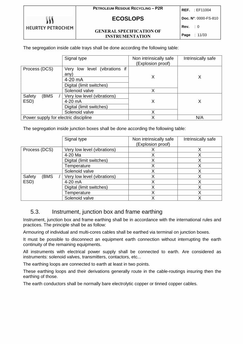
The segregation inside cable trays shall be done according the following table:
Signal type Non intrinsically safe (Explosion proof)
Intrinsically safe
Very low level (vibrations if any) 4-20 mA Digital (limit switches)
X
Process (DCS)
Solenoid valve X
X
Very low level (vibrations) 4-20 mA Digital (limit switches)
X Safety (BMS / ESD)
Solenoid valve X
X
Power supply for electric discipline X N/A
The segregation inside junction boxes shall be done according the following table:
Signal type Non intrinsically safe (Explosion proof)
Intrinsically safe
Very low level (vibrations) X X 4-20 Ma X X Digital (limit switches) X X Temperature X X
Process (DCS)
Solenoid valve X X Very low level (vibrations) X X 4-20 mA X X Digital (limit switches) X X Temperature X X
Safety (BMS / ESD)
Solenoid valve X X
5.3. Instrument, junction box and frame earthing Instrument, junction box and frame earthing shall be in accordance with the international rules and practices. The principle shall be as follow:
Armouring of individual and multi-cores cables shall be earthed via terminal on junction boxes.
It must be possible to disconnect an equipment earth connection without interrupting the earth continuity of the remaining equipments.
All instruments with electrical power supply shall be connected to earth. Are considered as instruments: solenoid valves, transmitters, contactors, etc...
The earthing loops are connected to earth at least in two points.
These earthing loops and their derivations generally route in the cable-routings insuring then the earthing of those.
The earth conductors shall be normally bare electrolytic copper or tinned copper cables.
PETROLEUM RESIDUE RECYCLING – P2R
ECOSLOPS
GENERAL SPECIFICATION OF
INSTRUMENTATION
REF. : EF11004
Doc. N° : 0000-FS-810
Rev. : 0
Page : 12/33
5.4. Design and installation of lightning protection No specific requirement for this point.
5.5. Instrumentation identification All instruments shall be clearly identified.
A permanent SS identification tag shall be attached to each field instrument.
Moreover, a traffolyte label with the tag number of the instrument shall be provided and mounted on the instrument support or close to the instrument and a second SS label with the tag number of the instrument shall be provided and mounted on the process isolation valve (when applicable) with a SS wire.
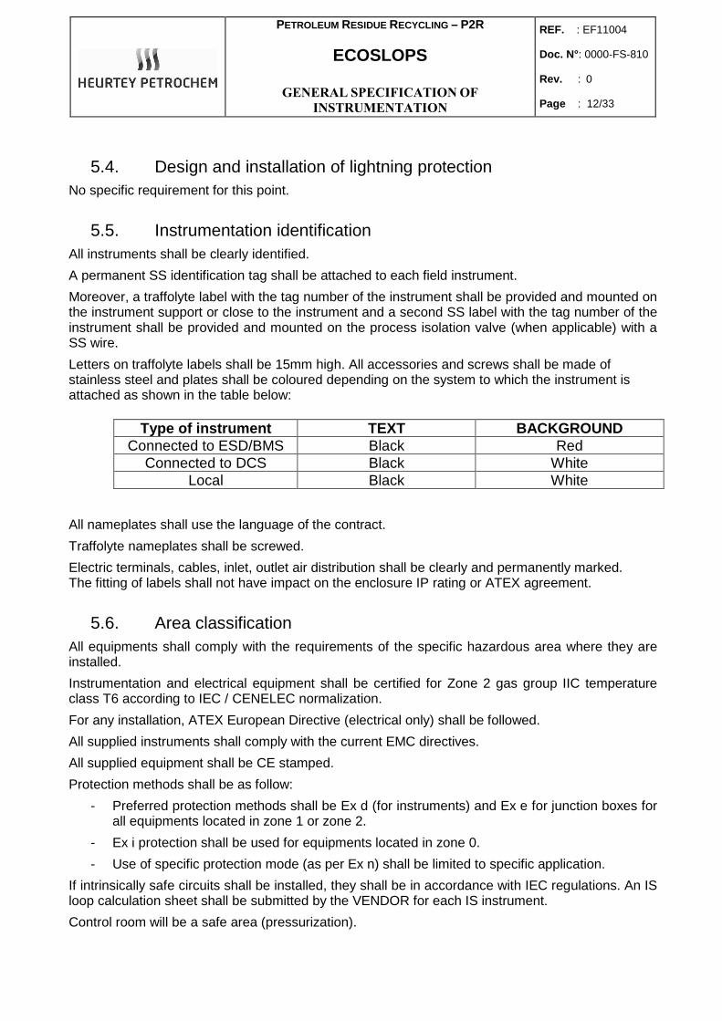
Letters on traffolyte labels shall be 15mm high. All accessories and screws shall be made of stainless steel and plates shall be coloured depending on the system to which the instrument is attached as shown in the table below:
Type of instrument TEXT BACKGROUND
Connected to ESD/BMS Black Red Connected to DCS Black White
Local Black White
All nameplates shall use the language of the contract.
Traffolyte nameplates shall be screwed.
Electric terminals, cables, inlet, outlet air distribution shall be clearly and permanently marked. The fitting of labels shall not have impact on the enclosure IP rating or ATEX agreement.
5.6. Area classification All equipments shall comply with the requirements of the specific hazardous area where they are installed.
Instrumentation and electrical equipment shall be certified for Zone 2 gas group IIC temperature class T6 according to IEC / CENELEC normalization.
For any installation, ATEX European Directive (electrical only) shall be followed.
All supplied instruments shall comply with the current EMC directives.
All supplied equipment shall be CE stamped.
Protection methods shall be as follow:
- Preferred protection methods shall be Ex d (for instruments) and Ex e for junction boxes for all equipments located in zone 1 or zone 2.
- Ex i protection shall be used for equipments located in zone 0.
- Use of specific protection mode (as per Ex n) shall be limited to specific application.
If intrinsically safe circuits shall be installed, they shall be in accordance with IEC regulations. An IS loop calculation sheet shall be submitted by the VENDOR for each IS instrument.
Control room will be a safe area (pressurization).
PETROLEUM RESIDUE RECYCLING – P2R
ECOSLOPS
GENERAL SPECIFICATION OF
INSTRUMENTATION
REF. : EF11004
Doc. N° : 0000-FS-810
Rev. : 0
Page : 13/33
5.7. Enclosure protection, environmental aspects, material and painting
Component parts of instruments shall be of material suitable for general refinery and chemical plant service, environmental and marine conditions (see site conditions).
All parts exposed to process fluid shall comply with the material defined in the piping service index for the corresponding piping class. Housings of transmitters shall be Epoxy or Polyurethane coated aluminium.
All field instruments shall be specified so that the operation is unaffected by ambient conditions: temperature extremes, freezing, excessive moisture, high humidity, dust, sun, heat, corrosive vapours or other adverse environmental conditions.
Design values of environmental conditions to be considered are stipulated in the technical attachments of each specific contract.
Depending on the location of equipments, one of the following enclosure protection degrees shall be selected for all instrumentation:
- Indoor IP 21
- Outdoor IP 65
Carbon steel shall never be used without protective paint (as per Manufacturer standard).
Site conditions:
The geographical locations of the P2R equipments are around the Mediterranean Sea.
The main conditions are: - Max ambient temperature : 43°C - Mini ambient temperature : -2°C - Seismicity - maximum acceleration for:
o Concrete structure : 5 m/s² o Metal structure : 8 m/s²
5.8. Winterizing / tracing Field instruments and accessories will be designed for operation at values of site conditions indicated in the specific contract.
Sun shade protection for each instrument will be supplied for transmitters equipped with LCD display and exposed directly to sun (last step of a skid, heater, etc…).
Process fluids in instruments and their connecting piping’s will be protected against the risk of freezing, crystallization or polymerization using tracing, heated enclosures or a seal liquid.
Each instrument system requiring heat shall be traced independently from process lines (except for pressure gauges) and other instrument systems.
PETROLEUM RESIDUE RECYCLING – P2R
ECOSLOPS
GENERAL SPECIFICATION OF
INSTRUMENTATION
REF. : EF11004
Doc. N° : 0000-FS-810
Rev. : 0
Page : 14/33
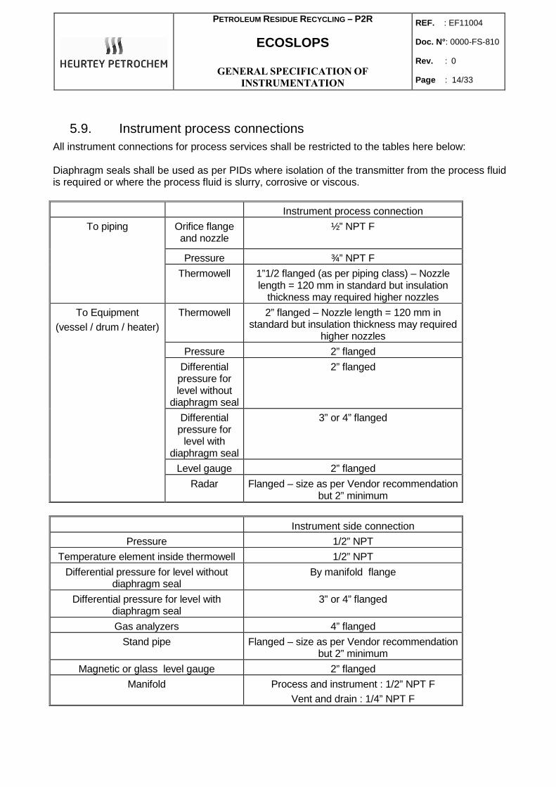
5.9. Instrument process connections All instrument connections for process services shall be restricted to the tables here below:
Diaphragm seals shall be used as per PIDs where isolation of the transmitter from the process fluid is required or where the process fluid is slurry, corrosive or viscous.
Instrument process connection
Orifice flange and nozzle
½” NPT F
Pressure ¾” NPT F
To piping
Thermowell 1”1/2 flanged (as per piping class) – Nozzle length = 120 mm in standard but insulation
thickness may required higher nozzles
Thermowell 2” flanged – Nozzle length = 120 mm in standard but insulation thickness may required
higher nozzles
Pressure 2” flanged
Differential pressure for level without
diaphragm seal
2” flanged
Differential pressure for
level with diaphragm seal
3” or 4” flanged
Level gauge 2” flanged
To Equipment (vessel / drum / heater)
Radar Flanged – size as per Vendor recommendation but 2” minimum
Instrument side connection
Pressure 1/2” NPT
Temperature element inside thermowell 1/2” NPT
Differential pressure for level without diaphragm seal
By manifold flange
Differential pressure for level with diaphragm seal
3” or 4” flanged
Gas analyzers 4” flanged
Stand pipe Flanged – size as per Vendor recommendation but 2” minimum
Magnetic or glass level gauge 2” flanged
Manifold Process and instrument : 1/2” NPT F Vent and drain : 1/4” NPT F
PETROLEUM RESIDUE RECYCLING – P2R
ECOSLOPS
GENERAL SPECIFICATION OF
INSTRUMENTATION
REF. : EF11004
Doc. N° : 0000-FS-810
Rev. : 0
Page : 15/33
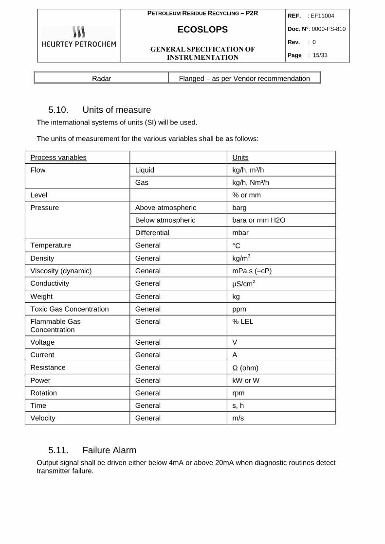
Radar Flanged – as per Vendor recommendation
5.10. Units of measure The international systems of units (SI) will be used.
The units of measurement for the various variables shall be as follows:
Process variables Units
Liquid kg/h, m³/h Flow
Gas kg/h, Nm³/h
Level % or mm
Above atmospheric barg
Below atmospheric bara or mm H2O
Pressure
Differential mbar
Temperature General °C
Density General kg/m3
Viscosity (dynamic) General mPa.s (=cP)
Conductivity General µS/cm2
Weight General kg
Toxic Gas Concentration General ppm
Flammable Gas Concentration
General % LEL
Voltage General V
Current General A
Resistance General Ω (ohm)
Power General kW or W
Rotation General rpm
Time General s, h
Velocity General m/s
5.11. Failure Alarm Output signal shall be driven either below 4mA or above 20mA when diagnostic routines detect transmitter failure.
PETROLEUM RESIDUE RECYCLING – P2R
ECOSLOPS
GENERAL SPECIFICATION OF
INSTRUMENTATION
REF. : EF11004
Doc. N° : 0000-FS-810
Rev. : 0
Page : 16/33
6. INSTRUMENTS SPECIFIC REQUIREMENTS
6.1. Generalities All instruments and accessories shall be chosen in the contractual VENDORS list (see appendix 1).
If Vendors propose to select an instrument which is not on the approved Vendor list, this will be highlighted to COMPANY in order to obtain COMPANY approval prior to procurement of instrument type.
All instrumentation shall conform to good engineering practice and procedures.
All sensors / transmitters and positionners shall be 4-20 mA, 24 Vdc.
All transmitters, positionners, limit switches and solenoid valves shall be connected by ISO M20 connection. ISO M25 will also be acceptable for the solenoid valves.
Cable-glands will be supplied by the CONTRACTOR when the electrical connections will be used. In this case, VENDOR shall supply plastic cap to avoid dust entry. But when spare connections exist, VENDOR shall supplied Stainless Steel explosion proof plugs.
Sensors / transmitters and valve electro-positionners shall be “Smart” type based on the HART protocol.
Most of instruments will work with vacuum conditions and shall be designed accordingly.
All transmitters, excepted of the temperature ones shall be equipped with a local LCD display.
Switches shall be avoided, excepted flame detection.
Mercury and asbestos are totally forbidden.
In case of dual transmitters (one for safety, one for control) for the same process measurement, they shall have the same range and span and the process connections will be fully independent, but shall also be close together to allow comparison of measurement.
6.2. Oxygen / CO Analyzers The measuring type “in situ” shall be used, with continue measure to ambient temperature from service temperature of furnace.
For the double measure of O2 and CO, a combination “in situ” probe in Zirconium oxide shall be used. Electronics shall be enclosed in a same housing. Measures of O2 and CO shall be readable on site.
O2/CO analyser shall be supplied with a calibration panel as per Vendor standard. Tubing and fittings shall be SS316.
Calibration bottles shall be supplied by the Vendor.
PETROLEUM RESIDUE RECYCLING – P2R
ECOSLOPS
GENERAL SPECIFICATION OF
INSTRUMENTATION
REF. : EF11004
Doc. N° : 0000-FS-810
Rev. : 0
Page : 17/33
6.3. Flow measurement Technology of flow instruments shall be chosen as per PIDs.
6.3.1. Differential pressure measurement
6.3.1.1. Primary elements
Concentric square edged orifice plates shall be used when possible on utilities fluids, as the standard primary element for all flow measurement of clean, non corrosive, non abrasive fluids and shall be calculated in accordance with standards ISO 5167.
The ß ration shall be between 0.3 and 0.7 for the primary elements.
Quadrant edged orifice plates are acceptable at low Reynolds numbers flow measurements (< 20.000).
Venturi or nozzle may be used only where the residual pressure drop must be very low.
Material of flow element shall be SS316 as a minimum.
6.3.1.2. Differential pressure range
The differential pressure ranges which may be used are 125, 250 mbar or 500 mbar.
The preferred range is 250 mbar.
The measured operating flow range shall be between 70 and 80% of calculated maximum flow range.
6.3.1.3. Differential pressure instruments
The square root calculation shall be done inside the transmitters (considering there is local indicator, for a direct reading of the flow).
Measuring elements shall be able to withstand pressure up to the rating of the body on either side without damaging the instrument or shifting the zero.
Differential flow transmitters shall be installed using SS manifold 5 valves.
Drain or vent connection will be provided.
6.3.2. Variable area flowmeter (Rotameter)
The armoured variable area flowmeter shall consist of an all metal metering tube with a magnetic type extension attached to a float.
Glass tube shall not be used.
Meter bodies are to be equipped with inlet and outlet float stops.
Connections shall be flanged, rating as per piping class.
Normal rotameter rangeability is 10 to 1 and meter will be selected so that normal flow falls at 50 to 60 % of maximum range.
PETROLEUM RESIDUE RECYCLING – P2R
ECOSLOPS
GENERAL SPECIFICATION OF
INSTRUMENTATION
REF. : EF11004
Doc. N° : 0000-FS-810
Rev. : 0
Page : 18/33
6.3.3. Electro-magnetic flow meters
Electro-magnetic flow meters are suitable for use for low resistivity liquids.
Connections shall be flanged, rating according to piping class.
6.3.4. Coriolis force mass flowmeter
Coriolis mass flowmeters may be used on almost any of the common process liquids, when wide rangeability and/or accuracy are required.
Measuring tubes shall be as per piping class.
If remote electronics is used, it shall be wired to sensor through a screened cable, supplied by VENDOR.
6.3.5. Vortex flow transmitters
Connections shall be flanged, rating and material connection according to piping class.
All electronics will be integrally mounted. Signal shall be standard with 2-wires system.
6.4. Level measurement Technology of level instruments shall be chosen as per PIDs.
6.4.1. Differential pressure type
For level measurement in atmospheric pressure tanks, a flanged hydrostatic pressure transmitter may be used.
Measuring elements shall be able to withstand pressure up to the rating of the body on either side without damaging the instrument or shifting the zero.
Differential pressure level transmitters shall be installed using SS manifold 5 valves.
Drain or vent connection will be provided.
6.4.2. Level gauges / magnetic level indication
Magnetic type indicators, with 2 colours flaps are preferred. The reading scale position shall be adjustable.
Magnetic type gauges shall be with SS 316 or 316L tube.
Visible length or indication shall cover, as a minimum, the range of the transmitter directly attached.
When level ranges exceed 2000 m, two or more devices will be installed to cover the specified range with an overlap of 50 mm minimum.
Reflex gauge glasses may be used for transparent process liquids and utility services. In this case, they shall be transparent type, without illuminators, and fitted with off-centered angle safety ball valves.
Mica shields will be provided in high steam service and with caustic fluids.
PETROLEUM RESIDUE RECYCLING – P2R
ECOSLOPS
GENERAL SPECIFICATION OF
INSTRUMENTATION
REF. : EF11004
Doc. N° : 0000-FS-810
Rev. : 0
Page : 19/33
6.4.3. Radar
Radar level transmitters may be probe guided microwaves or cone types, as per PIDs.
When radar level transmitters are mounted on a stand-pipe, this stand-pipe shall be supplied by the radar transmitter manufacturer.
If a stand-pipe is subject to the PED 97/23/CE, corresponding documentation shall be provided by the VENDOR.
The minimum stand-pipe diameter will be 2”, but may be higher as per Vendor recommendation.
6.5. Pressure measurement Over-range protection shall be provided for pressure instruments that may be subject to pressures that could damage or change the calibration of the instrument.
Elements in vacuum services shall be able to withstand full vacuum, regardless of range without taking a permanent set or going off calibration.
Instruments shall be equipped with pulsation dampeners externally adjustable when required by process conditions (pump outlet, etc…).
In services containing toxic, corrosive, slurred, viscous clogging or auto-ignitable material, diaphragm seal gauge protectors supplied integral with the pressure element or connected by sealed capillary tubing shall be used.
When it is not necessary to use capillaries or diaphragm, gage pressure instruments shall be provided with a 2-valves manifold.
When it is not necessary to use capillaries or diaphragm, differential pressure instruments shall be provided with:
- a 5-valves manifold, when the aim of the device is to measure a differential pressure - a 3-valves manifold when the aim of the device is to measure a so low relative
pressure than difference shall be made with the atmospheric pressure.
6.5.1. Pressure transmitters
For all instruments, primary measuring element material in contact with process fluid shall be SS 316 minimum.
Drain and vent shall be provided for each chamber.
6.5.2. Pressure Gauges
Primary measuring elements and movement shall be in SS minimum. Casing will also be in SS and equipped with a safety glass.
Pressure gauges shall have Bourdon tube, capsule or bellow measuring elements to meet the range requirements.
Bourdon tube pressure gauges shall be 100 mm diameter with white background and black figures. 150 mm dial shall be used fore capsule or bellow type.
Gauges cases shall be provided with suitable designed rupture disc or blow out back in the event of element rupture.
PETROLEUM RESIDUE RECYCLING – P2R
ECOSLOPS
GENERAL SPECIFICATION OF
INSTRUMENTATION
REF. : EF11004
Doc. N° : 0000-FS-810
Rev. : 0
Page : 20/33
The normal operating pressure shall be between 30 and 70% of the full scale measuring range.
Liquid filled pressure gauges shall be provided on pulsating service.
Range shall be selected from the following: - 0 to 1 / 1.6 / 2.5 / 4 / 6 / 10 / 16 / 25 / 40 / 60 barg - -1.013 to 0.6 / 1.5 / 3 / 6 bar
Accessories (siphons, pressure limiter, etc…) shall have ½” NPT connections and be SS316.
6.6. Temperature measurement 6.6.1. Thermowell
Temperature sensing elements will be installed in a thermowell except for special application as skin temperature measurement.
For thermowells, stress calculations shall be conformable to ASME PTC 19.3 standard and supplied by the manufacturer.
Thermowells will be threaded or flanged in accordance with CONTRACTOR standard.
All thermowells will be drilled from a solid bar stock stainless steel bar.
All test point thermowells shall be equipped with a screw cover or plug, complete with chain.
For pipes with a diameter below 4”, an increase in pipe diameter to 4” shall be made (as per CONTRACTOR standard).
6.6.2. Temperature transmitters and elements
Thermocouples and RTD detectors shall be supplied as a complete assembly. Converter shall be incorporated in the head, with a 4-20 mA output.
Thermocouples and RTD shall be mineral insulated, with a SS sheath.
Except for specific applications, RTD type Pt100, 3 wires shall be used for ranges between -200°C and 450°C.
Connection heads for thermocouples and RTD's will be of cast iron or aluminium and will be at least IP 65. Terminals will be identified. Hot junction will be ungrounded.
6.6.3. Temperature gauges
Indicating thermometers will be heavy-duty dial type, spring mounted head with every angle-type bi-metallic primary elements.
Pointer adjustment will be possible without removing the pointer from the shaft.
Minimum dial diameter will be 100 mm. Casing shall be of stainless steel suitable for mounting in threaded or flanged thermowells (as per CONTRACTOR standard).
6.7. Pressure Safety Valves The safety valves shall be conventional, balanced bellow or pilot operated type, according to the process conditions.
Semi-nozzle safety valves are allowed.
PETROLEUM RESIDUE RECYCLING – P2R
ECOSLOPS
GENERAL SPECIFICATION OF
INSTRUMENTATION
REF. : EF11004
Doc. N° : 0000-FS-810
Rev. : 0
Page : 21/33
Conventional safety valves shall be used as much as possible. Balanced and pilot-operated safety valves may be used for specific process conditions (variable back pressure, back pressure during discharge greater than 10% of the set pressure, etc…).
Relief valves will be designed (rating / construction material for body and bolting) according to the piping class. As a minimum, they will be flanged, bolted bonnet, metal-to-metal seated with a carbon steel body and stainless steel trim and spring.
For thermal relief valves, ¾” x 1” NPT screwed may be used.
Lifting levers shall be provided on steam service.
For all pressure safety valves, calculations shall be conformable to API RP 520 and supplied by the manufacturer. The valve size shall be based on size calculations for the worst of all cases that might cause the valve to blow. Noise and reaction forces calculations shall also appear on the sizing calculation sheets.
Valves accumulation factor shall be in accordance with the design codes used.
6.8. Control valves and Self Acting Regulator 6.8.1. General
Control valves shall be of the spring and diaphragm pneumatically actuated type.
The maximum noise level measured at 1 meter from the control valve shall not exceed 85 dBA.
For all control valves, calculations shall be conformable to ISA S75.01.01 and supplied by the manufacturer. Noise shall also appear on the sizing calculation sheets.
Control valves shall be able to open, shut off and move full stroke when operating with a differential pressure equal to the design pressure.
As a minimum requirement, control valve body and flange rating shall follow the piping class, with as a minimum, a carbon steel body and a SS316 trim.
Bonnets will be of the same material as the valve body and integral or bolted type construction with fully retained gasketing.
Control valves operating in toxic products will have bellow type packing.
All control valves will have a removable seat and plug, enclosed spring, position indicator, bolted packing gland and stainless steel identification tags.
Direction of flow shall be cast or stamped on the valve body.
Fail safe position shall be achieved through spring action.
The minimum allowable leakage for all control valves shall be class IV as per FCI70-2 standard, excepted when indicated on the PIDs.
6.8.2. Self Acting regulator (Pressure Control Valv e)
Self acting pressure regulators shall only be used in clean services and only in applications which do not need operator intervention.
6.8.3. Trim
The standard trim for control valves is SS316.
For steam applications, stellited trim shall be used.
PETROLEUM RESIDUE RECYCLING – P2R
ECOSLOPS
GENERAL SPECIFICATION OF
INSTRUMENTATION
REF. : EF11004
Doc. N° : 0000-FS-810
Rev. : 0
Page : 22/33
Hardened stainless steel or stellite shall be used in flashing services, fluids containing solid particles, high temperature steam and any services with a pressure drop greater than 10 bar.
6.8.4. Packing
The packing materials shall be PTFE base (temperature < 200°C) or graphite based (temperature comprised between 200 and 600°C).
It should not contain asbestos.
External lubricators or grease nipples shall not be used.
An extended bonnet may be used to keep the temperature at the stuffing box packing at an acceptable value.
6.8.5. Accessories
Positionners can easily be reversed by an internal adjustment.
Occasionally, split-range valve positionners require than one be reverse acting and one be direct acting.
Solenoid valves, when required, will be mounted between the positionner and the actuator.
Limit switches shall be of the “inductive” type.
The valve actuator and associated accessories shall be assembled, piped, aligned, tested and shipped as a unit by the valve manufacturer, according to the defined ITP.
6.9. Actuated on/off valves As a minimum requirement, safety valve body and flange rating shall follow the piping class, with as a minimum, a carbon steel body and a SS316 trim.
Torque calculations shall be supplied for each valve by the manufacturer. The actuators shall be sized with a safety coefficient of 1.5.
The type and action of safety valves will be defined by the PIDs. They will generally be full bore ball type to avoid pressure loss.
They shall be equipped with single acting spring return actuators.
The valve actuator and associated accessories shall be assembled, piped, aligned, tested and shipped as a unit by the valve manufacturer, according to the defined ITP.
All accessories (solenoid valves, limit switches, pressure regulators, gauges, etc…) shall be direct mounting on the valve and not remote mounting on SS panel, except when it is not possible.
Asbestos shall not be used for gland packing.
The minimum allowable leakage for all on/off valves shall be class IV, excepted when indicated on the PIDs.
Actuated valves shall normally be piloted by 24V dc solenoid valve.
Limit switches shall be of the “inductive” type.
PETROLEUM RESIDUE RECYCLING – P2R
ECOSLOPS
GENERAL SPECIFICATION OF
INSTRUMENTATION
REF. : EF11004
Doc. N° : 0000-FS-810
Rev. : 0
Page : 23/33
6.10. Rupture Disk (or Bursting disk) A rupture disk is usually specified using a MIN-MAX range of pressure at a specified temperature. When a MIN-MAX range is given by the Supplier, the other specific details necessary to specify are:
- The nominal burst pressure - The manufacturing range - The burst tolerance
The burst tolerance is always ±5% in accordance with all the rupture disk codes for stamped burst pressure equal to or greater than 40 PSIG (2.758 bar g) @ 22 ºC.
The burst tolerance varies, according to the particular disk design for stamped burst pressures below 40 PSIG @ 22 ºC.
Rupture disk shall be supplied with safety head and shall be equipped with a rupture electrical switch. Two supplementary disks shall be provided for each item as spare-parts.
7. CABLING / GLANDING
The cables used for general low voltage, and NIS shall be grey, and I.S. signal transmission shall be blue sheathed. The cables for thermocouples shall be in accordance with the international colour code according to IEC standards.
7.1. Technical Requirements of Cables All control cables shall be:
- Rodent resistant - Watertight - UV resistant - Direct sunlight exposure resistant - Aliphatic, Aromatics, Hydrocarbons resistant, mineral oils resistant, diesel oils resistant,
water resistant, glycol resistant, methanol resistant, etc … - Free Halogen, Low Smoke for all indoors cables (Technical Room, Control Room, …) - Armoured (for outdoor cables) - Un-armoured (for indoor cables) - Flame retardant as a minimum as per IEC 60 332 (Resistance of electrical cables to fire) or Fire resistant as per IEC 60-331 (Fire resisting characteristics of electric cables) for all inputs and outputs to F&G system.
7.2. Conductor material For single, pair, triad, quad, multi-cores, multi-pairs, multi-triads, the conductor material for each cable type shall be plain or metal-coated annealed copper.
All solid circular annealed copper conductors shall be class 1 (as defined in IEC 60 228 - Conductors of insulated cables).
All stranded circular annealed copper conductors shall be class 2 (as defined in IEC 60 228 - Conductors of insulated cables).
PETROLEUM RESIDUE RECYCLING – P2R
ECOSLOPS
GENERAL SPECIFICATION OF
INSTRUMENTATION
REF. : EF11004
Doc. N° : 0000-FS-810
Rev. : 0
Page : 24/33
7.3. Size of conductors/pairs/triads/quads
Type of cable Type of signal Section
Single pair/triad/quad - AI / AO / DI 0.88 mm²
Stranded conductor
Multi pairs/triads/quads - stranded conductor
- Thermocouple extension
- AI / AO / DI
1.00 mm²
0.5 mm²
Multi - Solid conductor - Thermocouple extension 0.5 mm²
Stranded conductor - DO 1.5 mm² minimum according to cable section calculation
7.4. Minimum Insulation grade The minimum insulation grade shall be:
- 250 V for Analogue (AI, AO) and Digital Input (DI) Signals - 1000 V for Digital Outputs (DO)
7.5. Core insulation For Flame Retardant cables, the core insulation shall be PVC.
For Fire Resistant or Halogen Free Low Smoke cables, cores shall be insulated with Silicon rubber or Polyethylene (XLPE).
For all cables, VENDOR shall supply data about resistance, capacitance and inductance.
7.6. Core twisting The insulated conductors shall be twisted to form a pair/triad/quad.
7.7. Collective / individual screen and drain wire All shields used for the different cables shall be Aluminum/polyester tape for Flame Retardant and copper/polyester tape for Fire Resistant, helically wound with minimum 30 % overlap.
The stranded tinned coated annealed copper drain wire(s) shall be 7 x 0.20 mm (cross section 0.5 mm²).
Shields shall equipped cables as per the following description:
PETROLEUM RESIDUE RECYCLING – P2R
ECOSLOPS
GENERAL SPECIFICATION OF
INSTRUMENTATION
REF. : EF11004
Doc. N° : 0000-FS-810
Rev. : 0
Page : 25/33
Type of cable Type of signal Individual
Screen
Overall
Screen
Single pair/triad/quad AI / AO / DI – IS & NIS - X
Multi pair/triad/quad AI / AO / DI - NIS - X
Multi pair/triad/quad AI / AO / DI - IS X X
Single pair/triad/quad Thermocouple extension
Very Low Voltage
Vibration
Displacement
- X
Multi pair/triad/quad Thermocouple extension
Very Low Voltage
Vibration
Displacement
X X
Notes:
- Multi-cores for Digital Output signal or for Power Supply cables (1.5, 2.5 and 4 mm²) shall not be screened. - IS : Intrinsically Safe - NIS : non intrinsically safe
7.8. Bedding, inner sheath
- Flame retardant : PVC - Fire resistant: Halogen Free Thermoplastic SHF1 - Free Halogen: Thermoplastic Halogen Free
7.9. Mechanical protection Pairs, triads, quad, multi-pairs, multi-triads, multi-cores cables laid indoors shall not be armored.
But unarmored cables shall be protected when potential mechanical damages are possible.
Cables laid indoor in Zone 1 or 2 of explosive areas shall be armored.
Pairs, triads, quads, multi-pairs, multi-triads, multi-cores cables laid outdoors shall be armored.
Armor shall be double steel tape, 0.2 mm thickness according to IEC 60228 (Conductors of insulated cables).
7.10. Outer sheath Outer sheath shall be rodent resistant, watertight, UV resistant, direct sunlight resistant, aliphatic hydrocarbon resistant… as per chapter 7.1 above.
It shall be in PVC for outdoor Flame Retardant or Fire Resistant cables and Halogen free Thermoplastic SHF1 for indoor Halogen Free cables.
PETROLEUM RESIDUE RECYCLING – P2R
ECOSLOPS
GENERAL SPECIFICATION OF
INSTRUMENTATION
REF. : EF11004
Doc. N° : 0000-FS-810
Rev. : 0
Page : 26/33
7.11. Cable Schedules All cables and tubes must be marked at both ends within one meter of the gland with cable markers.
7.12. Cable Tray/Ladders Physical location, aggressive environmental conditions and service must be considered when selecting the type of cable tray material and associated mechanical supports.
The sizing of tray must allow 30% spare capacity for future use. Cables should not be stacked more than two deep, and should be attached with plastic cable ties every 500 mm.
- Cable trays shall be of perforated type in steel galvanized.
- Cable tray sheet steel thickness shall be 1.5 mm as a minimum.
- Cable trays supports shall be in steel galvanized.
7.13. Field Cabling I.S Cables forming part of intrinsically safe systems shall be specified with the following requirements:
- The cable parameters L/R, C (L= inductance; R= resistance; C= capacitance) shall conform to the certificate requirements of the equipment to which they connect. These values shall be derived under fault condition in the cable which produces the worst case parameters.
- The limitations of cable parameters for intrinsically safe systems will be identified on the appropriate safety certificates supplied by the instrument manufacturers.
- The cable Vendor shall confirm actual cable parameters as required by the specification. - Screens shall only be earthed at the equipment room panel end to the I.S. earth bus bar,
but continuity must be maintained from the instrument where the screen must be installed.
7.14. Field Cabling non-I.S. Screens shall only be earthed at the equipment room panel end to the instrument earth bus bar, but continuity must be maintained from the instrument where the screen must be installed.
7.15. Field Cabling Termination and Junction boxes IS junction boxes shall have a particular “IS” marking.
Only one multi-core cable shall be connected to each junction box.
All cables shall enter the bottom part of JB only. No side or top entry is allowed.
As they are made of reinforced polyester, junction boxes shall be provided with 316 stainless steel gland plate for cable gland earthing.
The gland plate shall be earthed.
Dedicated terminals shall be used for overall and individual cable screen termination in JB.
Screwed type terminals shall be used.
Junction boxes and field panels shall be labelled using engraved Traffolyte plates or similar. Letters shall be 15mm high. All accessories and screws shall be made of stainless steel.
Plates shall be coloured as follows:
PETROLEUM RESIDUE RECYCLING – P2R
ECOSLOPS
GENERAL SPECIFICATION OF
INSTRUMENTATION
REF. : EF11004
Doc. N° : 0000-FS-810
Rev. : 0
Page : 27/33
JUNCTION BOXES TEXT BACKGROUND Process (DCS) - IS Black Blue
Process (DCS) - NIS Black White Safety (ESD) -IS Red Blue
Safety (ESD) - NIS Black Red
Notes: NIS: Non Intrinsically safe IS: Intrinsically safe
7.16. Equipment Room 7.16.1. Cabling General
All multi-core cables to and from the field shall be terminated in a marshalling cabinet prior to connection to any equipment room equipment or cabinets.
Wiring types between cabinets shall be as follows: - Digital signals : Twisted pair, screened - Analogue signals : Twisted pair, screened - DC Power Supplies : 2-core - AC Power Supplies : 3-core - Earthing : Single core
Segregation between I.S., non-I.S., power and general purpose cabling shall be maintained by use of separate trunking, cable tray or ladder rack.
7.16.2. Equipment Room Cabling I.S
Field I.S. multi-core cable shall be terminated on dedicated termination rails within the marshalling cabinet(s).
I.S. terminals shall be blue within the marshalling cabinets.
7.16.3. Equipment Room cabling non-I.S
Field non-I.S. multi-core cable shall be terminated on dedicated termination rails within the marshalling cabinet(s).
Non-I.S. terminals shall be grey within the marshalling cabinets.
All spare pairs shall be bonded to the Instrument earth bar within the marshalling cabinet.
7.17. Power supplies AC and DC AC power supply cable shall be 3 cores for AC and 2 cores for DC
Conductors shall be stranded and the minimum conductor size shall be 1.5 mm².
Supply cabling within the equipment room shall be PVC sheathed only.
Supply cabling for applications exterior to the equipment room shall be PVC with steel armour.
PETROLEUM RESIDUE RECYCLING – P2R
ECOSLOPS
GENERAL SPECIFICATION OF
INSTRUMENTATION
REF. : EF11004
Doc. N° : 0000-FS-810
Rev. : 0
Page : 28/33
7.18. Glanding Cable glands shall be certified for use in accordance with the equipment certification. In general Eex (e) glands shall be used except when connecting to ex (d) equipment where ex (d) glands shall be used.
Cable glands for armoured cable shall be of the type which includes facilities for securing and bonding the armour.
8. IDENTIFICATION
8.1. Identification of Junction boxes Each junction box shall bear the following identification: X-B-C-D-001 to X-B-C-D-999, where:
- X: Unit number
o 0 : Heating & Distillation + Burner Skid o 1 : Storage o 2 : P2R Utilities o 3 to 9 : Client Packages
- B: Junction box o non intrinsically safe = JB o Junction box intrinsically safe = JBI
- C: Instrument connected to o DCS system = D o ESD system = E o F&G system = F o Power supply for instrument = U o Instruments connected to package = X
- D: Signal type
o Analogue signal = M o Digital signal = C o Solenoid valve signal = S o Signal for temperature= T o Miscellaneous signal (Frequency, vibration) = X
However, serial numbering for field instrument junction boxes shall start from 001 to 999. Example:
- 0-JBIES-001 shall identify a junction box, intrinsically safe, used for solenoid signals connected to ESD.
- 3-JBES-002 shall identify a junction box for a package, non intrinsically safe, used for solenoid signals connected to ESD.
PETROLEUM RESIDUE RECYCLING – P2R
ECOSLOPS
GENERAL SPECIFICATION OF
INSTRUMENTATION
REF. : EF11004
Doc. N° : 0000-FS-810
Rev. : 0
Page : 29/33
8.2. Cable between instrument and junction boxes or local control panel
The required identification shall be instrument tag number with additional letter "C" or "CI" (when intrinsic safe loop) added just before the function letters. The cable tag number shall be indicated on the cable at both ends.
The instrument tag number + terminal number separated by a dash shall be indicated on each end of the wire in the cable at both ends.
Example:
Instrument Cable 2 wires in cable Junction box
FT001 CFT001 FT001-1 0JBDM001 FT001-2
8.3. Multi-cable between junction box or local control panel and marshalling cabinet
Multi-core/Multi-pair cable shall bear the same tag as the junction box where it is connected, and the letter, "C" shall replace "JB". For LCP, the letter “C” shall precede “LCP”. When cable is used within intrinsically safe circuit an "I" shall be added after the "C".
Example:
Junction box Multi-core/Multi-pair
0JBEM073 0CEM073
8.4. Tagging of cables and wires Cables shall be tagged at all termination points, and specifically when :
- leaving the instrument
- entering and exiting the JB
- entering and exiting the marshalling cabinets
- Terminating in the system cabinet.
Tags for outdoor cables shall be made of punched SS316L labels “PARTEX-PKS” type or similar attached with stainless steel fasteners, while indoor cables shall be PVC “PARTEX-PK” type or similar, with black text on white strap.
Use of slip-on pre-printed shrinkable sleeves shall be reserved for cable applications where risk of corruption of marking with dirt is very limited; it shall be subject to HPC approval.
Wires from indoor cables shall be tagged with colour coded rings “PARTEX-PY” type or equivalent. These rings shall be correctly sized for diameter; labelling text shall correspond to terminal numbers.
Wires from outdoor cables shall be tagged with flexible slip-on PARTEX-PO” type or equivalent; labelling text shall correspond to instrument tag and terminal number.
All cables used for earthing are identified by coloured sleeves.
PETROLEUM RESIDUE RECYCLING – P2R
ECOSLOPS
GENERAL SPECIFICATION OF
INSTRUMENTATION
REF. : EF11004
Doc. N° : 0000-FS-810
Rev. : 0
Page : 30/33
9. PIPING, TUBING & FITTING
9.1. Generalities Any piping system or process connection should be designed in accordance with the requirements of the service to which it connects (e.g. sterile service, high pressure etc.). This should include the wetted parts of the instrument concerned.
Pressurized impulse lines (e.g. steam pressure transmitters) must be run in 12 mm O.D 1.5 mm wall thickness, 316 stainless steel using compression fittings, double ferrule.
9.2. Process Impulse Lines Impulse tubing shall normally be high quality stainless steel fully annealed cold drawn, free from scratches, suitable for bending and flaring, tube to ASTM A-269 or equivalent. Tubing shall normally be 12 mm OD unless otherwise agreed.
Where instruments contain large inventories of process fluid, such as level transmitters, vents and drains shall be in accordance with the piping specification. For all other instrumentation, small volumes of process fluid may be vented and drained to atmosphere providing that safe disposal can be assured.
Instrument tubing shall be protected by steam tracing and insulated when the containing fluid is normally static and subject to freezing, or when it may become viscous at ambient temperature.
Impulse piping shall be in accordance with the appropriate Instrument hook-up. Material required for each hook-up shall be listed in the relevant schedules.
9.3. Valving Primary isolation shall normally be made by the Piping Department and shall be in accordance with the piping specification for the application.
Secondary isolation shall normally be made by the Instrument Department.
9.4. Fittings Instrument connections for impulse tubing shall normally be 12 mm OD.
Process impulse tube fittings shall be twin ferrule type AISI 316L.
10. FIELD INSTALLATION
All field instruments of any type including primary temperature elements, control valves; regulators etc ... shall be mounted in a position that will make them readily accessible from grade or an operating platform.
Connections and instrument mountings shall be oriented so that instruments or connecting piping will not obstruct or block aisles or platforms.
All instruments shall be located to provide maintenance access. In general, ready accessibility shall be defined as the device being mounted between 0.9 m and 1.7 m above grade or permanent operator platform and a person being able to reach all surfaces.
PETROLEUM RESIDUE RECYCLING – P2R
ECOSLOPS
GENERAL SPECIFICATION OF
INSTRUMENTATION
REF. : EF11004
Doc. N° : 0000-FS-810
Rev. : 0
Page : 31/33
If necessary, a primary temperature element or similar device may be considered accessible if it can be easily reached from a ladder or stairway which is permanent part of the steel structure.
In the case of devices mounted in the piping, the piping shall be so designed as to make the device accessible as defined above.
11. PACKAGES
Basically, two types of packages shall be considered:
11.1. P1 type packages The package is delivered with its instruments but without cables. However the cable trays and their related supports shall be provided until the package battery limit.
This type corresponds to packages with few instruments.
These packages are fully controlled by the PCS &/or ESD.
11.2. P2 type packages The package is equipped with its instruments, cables and cable routings. Instruments are wired and connected up to junction boxes.
This package type is foreseen for packages with many instruments whose control and safety logic is simple and does not exist as standard supply by the VENDOR or for packages considered as integral part of the facility process functions.
These packages are fully controlled by the PCS &/or ESD. The Package VENDOR shall provide the CONTRACTOR with a detailed functional analysis to be forwarded to the PCS &/or ESD contractor. The VENDOR shall be involved in the PCS &/or ESD FAT to validate the control and safety algorithms.
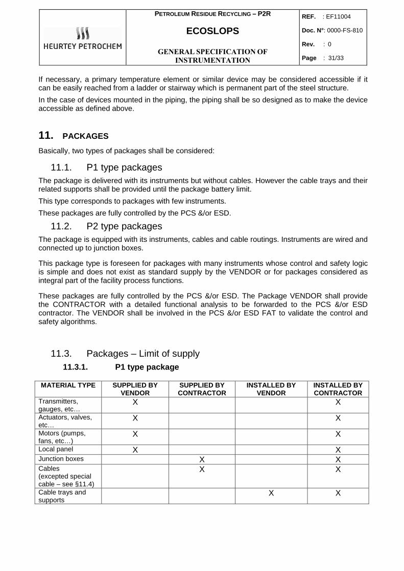
11.3. Packages – Limit of supply 11.3.1. P1 type package
MATERIAL TYPE SUPPLIED BY
VENDOR SUPPLIED BY CONTRACTOR
INSTALLED BY VENDOR
INSTALLED BY CONTRACTOR
Transmitters, gauges, etc…
X X
Actuators, valves, etc…
X X
Motors (pumps, fans, etc…)
X X
Local panel X X Junction boxes X X Cables (excepted special cable – see §11.4)
X X
Cable trays and supports
X X
PETROLEUM RESIDUE RECYCLING – P2R
ECOSLOPS
GENERAL SPECIFICATION OF
INSTRUMENTATION
REF. : EF11004
Doc. N° : 0000-FS-810
Rev. : 0
Page : 32/33
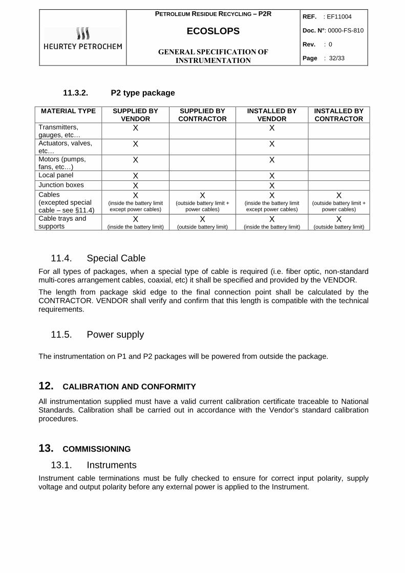
11.3.2. P2 type package MATERIAL TYPE SUPPLIED BY
VENDOR SUPPLIED BY CONTRACTOR
INSTALLED BY VENDOR
INSTALLED BY CONTRACTOR
Transmitters, gauges, etc…
X X
Actuators, valves, etc…
X X
Motors (pumps, fans, etc…)
X X
Local panel X X Junction boxes X X Cables (excepted special cable – see §11.4)
X (inside the battery limit except power cables)
X (outside battery limit +
power cables)
X (inside the battery limit except power cables)
X (outside battery limit +
power cables) Cable trays and supports
X (inside the battery limit)
X (outside battery limit)
X (inside the battery limit)
X (outside battery limit)
11.4. Special Cable For all types of packages, when a special type of cable is required (i.e. fiber optic, non-standard multi-cores arrangement cables, coaxial, etc) it shall be specified and provided by the VENDOR.
The length from package skid edge to the final connection point shall be calculated by the CONTRACTOR. VENDOR shall verify and confirm that this length is compatible with the technical requirements.
11.5. Power supply
The instrumentation on P1 and P2 packages will be powered from outside the package.
12. CALIBRATION AND CONFORMITY
All instrumentation supplied must have a valid current calibration certificate traceable to National Standards. Calibration shall be carried out in accordance with the Vendor’s standard calibration procedures.
13. COMMISSIONING
13.1. Instruments Instrument cable terminations must be fully checked to ensure for correct input polarity, supply voltage and output polarity before any external power is applied to the Instrument.

PETROLEUM RESIDUE RECYCLING – P2R
ECOSLOPS
GENERAL SPECIFICATION OF
INSTRUMENTATION
REF. : EF11004
Doc. N° : 0000-FS-810
Rev. : 0
Page : 33/33
13.2. Loops Once the Instrument check has been completed, all devices in the loop must be checked for compliance with the loop requirements. This may include, but not be limited to, local indicators, remote indicators, panel mimic displays, computer / system inputs and outputs, computer screen mimics and any software communications to other computer systems.
14. MATERIAL INSPECTION
CONTRACTOR reserves the right to inspect and witness testing of all instrumentation and electrical wiring prior to shipment from VENDOR'S factory. Before CONTRACTOR'S inspection, VENDOR'S engineers shall have carefully inspected, checked, and tested all instrumentation to verify full compliance with the drawings and specifications listed in the Requisition.
Particular attention shall be given (for package unit) to:
a. Accessibility.
b. Impulse line Hook-ups.
c. Straight length requirements for orifice plate and control valve installations.
d. Supporting arrangements.
e. General aspects such as the colour scheme for control panels, etc..
f. Colour coding, if applicable.
g. Quality of wiring/cabling.
h. In-line instruments.
i. Earthing connections.
j. Painting.
All instruments supplied by the VENDOR shall have calibration certificates signed by the engineer of the MANUFACTURER or his sub-supplier. These documents shall be available during inspection.
It shall be ensured that the MANUFACTURER has a competent person for the above duty.
A typical calibration certificate shall be submitted to the CONTRACTOR for approval. This certificate will be incorporated in the final manufacturing report.
If calibration certificates are not available, the inspector shall witness the calibration of not less than 20% of each type of instrument. This shall be increased to 100%, if discrepancies are found.
In a general way the VENDOR will supply before inspection of the instruments or equipments a document "functional test plan" and\or a procedure of inspection.
Every inspection of instruments or equipments will be validated by a written report.
In the case or instruments or special equipments should be inspected, the CONTRACTOR could bring specialized companies, such as:
- APAVE
- INERIS
- NORISKO
- Others...