Embed Size (px)
DESCRIPTION
Manual Rescate
Citation preview
General RescueManual
New Zealand Civil DefenceEmergency Management
August 2001

Page i
Table of ContentsFOREWORD........................................................................................................................................................ 1
EXPLANATION OF WARNING NOTES ..................................................................................................... 1URBAN SEARCH AND RESCUE ................................................................................................................. 2PHOTOGRAPHS.............................................................................................................................................. 2NZQA UNIT STANDARDS............................................................................................................................ 2
CHAPTER ONE RESCUE................................................................................................................................. 3
THE AIM OF RESCUE.................................................................................................................................... 3FUNCTIONS..................................................................................................................................................... 3THE PSYCHOLOGY OF RESCUE................................................................................................................ 4RESCUE WORKERS....................................................................................................................................... 5
Group 1 – Survivors ..................................................................................................................................... 5Group 2 – Untrained Personnel .................................................................................................................. 5Group 3 – Trained Personnel ...................................................................................................................... 6
PERSONAL TRAITS OF THE RESCUER .................................................................................................... 6PERSONAL BEHAVIOUR ............................................................................................................................. 7TEAM COMPOSITION................................................................................................................................... 8ACTIVATION .................................................................................................................................................. 8DEPLOYMENT................................................................................................................................................ 9COORDINATED INCIDENT MANAGEMENT SYSTEM.......................................................................... 9
CHAPTER TWO SAFETY IN TRAINING AND OPERATIONS............................................................. 11
INTRODUCTION........................................................................................................................................... 11THE RESPONSIBILITY FOR SAFETY ...................................................................................................... 11BASIC PRECAUTIONS ................................................................................................................................ 12RESCUE / SAFETY HARNESSES............................................................................................................... 13CASUALTY SAFETY ................................................................................................................................... 14SAFE WORKING IN A CONFINED SPACE.............................................................................................. 14MOVING IN AN UNKNOWN ENVIRONMENT....................................................................................... 16SEARCHING A DARKENED ROOM ......................................................................................................... 18VEHICLE SAFETY ....................................................................................................................................... 18EQUIPMENT SAFETY ................................................................................................................................. 19PUBLIC UTILITY HAZARDS ..................................................................................................................... 19
General ....................................................................................................................................................... 19Gas (CNG and LPG).................................................................................................................................. 20Water........................................................................................................................................................... 20Sewers......................................................................................................................................................... 21Electricity ................................................................................................................................................... 21
CORRECT LIFTING TECHNIQUES........................................................................................................... 22TEAM LIFTING............................................................................................................................................. 23
CHAPTER THREE RECONNAISSANCE.................................................................................................... 25
THE RESCUE PLAN ..................................................................................................................................... 25RECONNAISSANCE & RESCUE BY STAGES ........................................................................................ 25
Reconnaissance & Survey.......................................................................................................................... 26Elimination of Utilities............................................................................................................................... 27Primary Surface Search & Rescue ............................................................................................................ 27Exploration Of All Voids And Spaces........................................................................................................ 27

Page ii
Access By Selected Debris Removal.......................................................................................................... 28Termination by General Debris Removal ................................................................................................. 28
THE APPRECIATION PROCESS ................................................................................................................ 28Step One – Define The Problem ................................................................................................................ 28Step Two – State The Aim .......................................................................................................................... 29Step Three – Consider The Factors........................................................................................................... 29Step Four – Determine Courses Open ...................................................................................................... 29Step Five – Decide On Best Course .......................................................................................................... 30Step Six – Plan............................................................................................................................................ 30
CONTINUING ACTION ............................................................................................................................... 30CALLING AND LISTENING TECHNIQUES ............................................................................................ 31DAMAGE TO BUILDINGS.......................................................................................................................... 32TYPES OF BUILDINGS................................................................................................................................ 33
Light Timber Framed................................................................................................................................. 33Unreinforced Masonry............................................................................................................................... 33Reinforced Concrete Masonry (Blockwork).............................................................................................. 33Concrete Tilt-Up ........................................................................................................................................ 33Reinforced Concrete/Structural Steel........................................................................................................ 33
TYPES OF COLLAPSE................................................................................................................................. 34The ‘V’ Type Collapse................................................................................................................................ 34The ‘Lean To’ Collapse ............................................................................................................................. 35The ‘Horizontal/Pancake’ Type Collapse ................................................................................................. 35
PRECAUTIONS IN OPERATIONS ............................................................................................................. 36CRUSH INJURIES ......................................................................................................................................... 36DEBRIS CLEARANCE ................................................................................................................................. 37
When Debris Clearance Is Necessary ....................................................................................................... 37Methods Of Debris Clearance ................................................................................................................... 38Precautions In Operations......................................................................................................................... 38
BUILDING MARKING ................................................................................................................................. 39General Area Marking............................................................................................................................... 39
VICTIM MARKING ...................................................................................................................................... 42OTHER MARKINGS:.................................................................................................................................... 43THE DEAD ..................................................................................................................................................... 44
Identification And Removal ....................................................................................................................... 44Suspicious Circumstances.......................................................................................................................... 45Conduct At The Scene ................................................................................................................................ 45
CHAPTER FOUR ROPES, TAPES, KNOTS & LASHINGS – GENERAL INFORMATION............. 47
INTRODUCTION........................................................................................................................................... 47IDENTIFICATION......................................................................................................................................... 47RECORD SYSTEMS ..................................................................................................................................... 47ROPE ............................................................................................................................................................... 48TYPES OF ROPE ........................................................................................................................................... 48TERMINOLOGY ........................................................................................................................................... 48ROPE PACKAGING...................................................................................................................................... 51
Stuff Sacks................................................................................................................................................... 51Chaining ..................................................................................................................................................... 51
ROPE PACKAGING (CARRYING)............................................................................................................. 53CLIMBING TAPES........................................................................................................................................ 53
Construction ............................................................................................................................................... 54Size.............................................................................................................................................................. 54Abrasion...................................................................................................................................................... 54Tape Strength ............................................................................................................................................. 54The Use of Tape.......................................................................................................................................... 55Care and Maintenance............................................................................................................................... 55Safety........................................................................................................................................................... 55

Page iii
FLEXIBLE STEEL WIRE ROPES (SWR)................................................................................................... 57Safe Working Load (SWL) ......................................................................................................................... 57Construction ............................................................................................................................................... 57Precautions in Operations ......................................................................................................................... 58Inspection of Steel Wire Rope.................................................................................................................... 58Storage of Steel Wire Ropes....................................................................................................................... 59
VERTICAL LIFT KNOT ............................................................................................................................... 60CHAIR KNOT ................................................................................................................................................ 61
Chair Knot – Alternate Method ................................................................................................................. 61LASHINGS ..................................................................................................................................................... 62
Square Lashing........................................................................................................................................... 62Diagonal Lashing....................................................................................................................................... 63Round Lashing............................................................................................................................................ 63Figure of Eight Lashing ............................................................................................................................. 64
CHAPTER FIVE SYNTHETIC ROPES - KNOTS...................................................................................... 65
CONSTRUCTION.......................................................................................................................................... 65POLYAMIDE (NYLON) ............................................................................................................................... 66KERNMANTEL CONSTRUCTION............................................................................................................. 66STATIC KERNMANTEL ROPES ................................................................................................................ 67
Strength Vs Handling ................................................................................................................................. 67CHARACTERISTICS OF A SYNTHETIC FIBRE STATIC RESCUE ROPE.......................................... 68CARE AND MAINTENANCE...................................................................................................................... 68WASHING ROPES ........................................................................................................................................ 69INSPECTION.................................................................................................................................................. 70RETIRING A ROPE....................................................................................................................................... 71RATED STRENGTH AND SAFE WORKING LOAD ............................................................................... 72POLYAMIDE DYNAMIC CLIMBING ROPES.......................................................................................... 72SMALL DIAMETER KERNMANTEL CORDS ......................................................................................... 73OTHER SYNTHETIC FIBRE ROPES.......................................................................................................... 73
Materials..................................................................................................................................................... 73Rated Strength and Safe Working Load .................................................................................................... 73Care, Maintenance, and Safe Operations ................................................................................................. 74
KNOTS............................................................................................................................................................ 74Stopper Knot............................................................................................................................................... 74
KNOTS FOR SYNTHETIC FIBRE RESCUE ROPES................................................................................ 74Thumb Knot ................................................................................................................................................ 74Figure 8 Knots............................................................................................................................................ 75Figure 8 Knot (Single Figure 8) ................................................................................................................ 75Rethreaded Figure 8 .................................................................................................................................. 76Figure 8 Joining Knot (Figure 8 Bend)..................................................................................................... 76Double Figure 8 on a Bight (Anchor 8 or Industrial 8) ........................................................................... 77Round Turn and Two Half Hitches............................................................................................................ 77Alpine Butterfly .......................................................................................................................................... 78Double Fisherman’s Knot.......................................................................................................................... 79Prusik Knot................................................................................................................................................. 80Friction Hitch............................................................................................................................................. 81
CHAPTER SIX NATURAL FIBRE ROPES - KNOTS ............................................................................... 83
INTRODUCTION........................................................................................................................................... 83CONSTRUCTION.......................................................................................................................................... 83CARE AND MAINTENANCE...................................................................................................................... 84INSPECTION OF LAID ROPE..................................................................................................................... 85RATED STRENGTH AND SAFE WORKING LOAD (SWL)................................................................... 86ROPE PACKAGING...................................................................................................................................... 87WHIPPING ROPE ENDS .............................................................................................................................. 87

Page iv
KNOTS............................................................................................................................................................ 87General Purpose Knots.............................................................................................................................. 88
KNOT SAFETY.............................................................................................................................................. 92KNOT STRENGTH........................................................................................................................................ 92
CHAPTER SEVEN ANCHORS AND HOLDFASTS................................................................................... 93
INTRODUCTION........................................................................................................................................... 93NATURAL ANCHORS ................................................................................................................................. 93CONSTRUCTED ANCHORS ....................................................................................................................... 93
Picket Holdfasts.......................................................................................................................................... 93Buried Holdfasts......................................................................................................................................... 95Log And Picket Holdfasts........................................................................................................................... 96
IMPROVISED ANCHORS............................................................................................................................ 96PRECAUTIONS IN OPERATIONS ............................................................................................................. 96SELECTION OF ANCHORS ........................................................................................................................ 97SLING LOADING ANGLES......................................................................................................................... 97ATTACHMENT TO ANCHORS .................................................................................................................. 98KARABINERS ............................................................................................................................................... 99SHACKLES .................................................................................................................................................. 101SAFETY SUMMARY.................................................................................................................................. 102
CHAPTER EIGHT LADDERS ..................................................................................................................... 103
INTRODUCTION......................................................................................................................................... 103CONSTRUCTION........................................................................................................................................ 103EXTENSION LADDERS............................................................................................................................. 103STEPLADDERS ........................................................................................................................................... 104TERMINOLOGY ......................................................................................................................................... 105SINGLE RESCUER LADDER RAISE....................................................................................................... 106ERECTING AND EXTENDING THE LADDER (TWO RESCUERS) ................................................... 106ERECTING AND EXTENDING THE LADDER (THREE RESCUERS) ............................................... 107ANGLE OF LADDERS WHEN RAISED .................................................................................................. 108OVERLAPS .................................................................................................................................................. 108SECURING THE HEAD OF THE LADDER............................................................................................. 109SECURING THE FOOT OF THE LADDER ............................................................................................. 109HALVING LADDERS................................................................................................................................. 109LADDER CLIMBING.................................................................................................................................. 110HELPING A CASUALTY DOWN A LADDER........................................................................................ 111MAINTENANCE AND TESTING ............................................................................................................. 112
CHAPTER NINE CASUALTY HANDLING TECHNIQUES.................................................................. 113
INTRODUCTION......................................................................................................................................... 113TRIAGE......................................................................................................................................................... 114CASUALTY SORTING............................................................................................................................... 115CASUALTY TAGS...................................................................................................................................... 116STRETCHERS.............................................................................................................................................. 116FOLDING OR POLE STRETCHERS......................................................................................................... 117BLANKETING THE STRETCHER............................................................................................................ 118LOADING A STRETCHER ........................................................................................................................ 120
The Four Rescuer Method ....................................................................................................................... 120Blanket Lift (Four Or Six Rescuers)........................................................................................................ 121Clothing Lift (Three Rescuers) ................................................................................................................ 122Webbing Bands (Five Rescuers).............................................................................................................. 122Specialist Lifting/Loading Devices.......................................................................................................... 123
LASHING THE CASUALTY TO THE STRETCHER.............................................................................. 123Lashing - Lateral/Recovery Position....................................................................................................... 124

Page v
BOARD RESCUE STRETCHERS.............................................................................................................. 125Board Rescue Stretcher Lashing ............................................................................................................. 126Attaching Lowering Lines To The Board Rescue Stretcher ................................................................... 127
BASKET STRETCHERS............................................................................................................................. 127Blanketing A Basket Stretcher ................................................................................................................. 128Securing A Basket Stretcher With Securing Straps................................................................................. 128Securing A Basket Stretcher By Lashing................................................................................................. 129
WRAP AROUND STRETCHERS .............................................................................................................. 130MOVING A STRETCHER OVER UNEVEN GROUND.......................................................................... 131MOVING A STRETCHER IN CONFINED SPACES............................................................................... 132PASSING A STRETCHER OVER A GAP................................................................................................. 133
CHAPTER TEN IMPROVISED CASUALTY MOVEMENT.................................................................. 135
RESCUE TECHNIQUES USING NO EQUIPMENT................................................................................ 135ONE RESCUER HANDLING TECHNIQUES .......................................................................................... 135
One Rescuer Human Crutch.................................................................................................................... 135Pick-A-Back.............................................................................................................................................. 136Pack Strap Carry...................................................................................................................................... 136Fire-Fighter’s Crawl................................................................................................................................ 137Removal Down Stairs Method ................................................................................................................. 137
TWO RESCUER HANDLING TECHNIQUES ......................................................................................... 138Two Rescuer Human Crutch.................................................................................................................... 138Two-Handed Seat ..................................................................................................................................... 138Three-Handed Seat................................................................................................................................... 138Four-Handed Seat.................................................................................................................................... 139The ‘Fore and Aft’ Method ...................................................................................................................... 139
IMPROVISED STRETCHERS.................................................................................................................... 140Platform Stretchers .................................................................................................................................. 140Pole Stretchers ......................................................................................................................................... 140Bush Stretchers......................................................................................................................................... 141Ladders ..................................................................................................................................................... 141Chairs ....................................................................................................................................................... 142
CHAPTER ELEVEN LIFTING & LOWERING TECHNIQUES........................................................... 143
INTRODUCTION......................................................................................................................................... 143MECHANICAL LOWERING METHODS ................................................................................................ 143STRETCHER OPERATIONS...................................................................................................................... 144GUIDE AND SAFETY LINES.................................................................................................................... 144IMPROVISED SINGLE POINT LOWER .................................................................................................. 144TWO-POINT VERTICAL SUSPENSION.................................................................................................. 145FOUR-POINT HORIZONTAL SUSPENSION.......................................................................................... 147LADDER HINGE ......................................................................................................................................... 148LADDER SLIDE .......................................................................................................................................... 150LADDER DERRICK.................................................................................................................................... 152THE JIB......................................................................................................................................................... 154TRIPODS (OR GYNS)................................................................................................................................. 156
CHAPTER TWELVE PULLEY SYSTEMS, WINCHES & LIFTING EQUIPMENT......................... 159
PULLEY SYSTEMS .................................................................................................................................... 159TERMINOLOGY ......................................................................................................................................... 159TYPES OF PULLEYS.................................................................................................................................. 160CHARACTERISTICS OF A LIGHTWEIGHT RESCUE PULLEY......................................................... 161CONSTRUCTING PULLEY SYSTEMS.................................................................................................... 161TYPES OF PULLEY SYSTEMS................................................................................................................. 162MECHANICAL ADVANTAGE.................................................................................................................. 162

Page vi
IMPROVISED HOOK MOUSING ............................................................................................................. 163PRECAUTIONS IN OPERATIONS ........................................................................................................... 163LIFT / LOWER ROPE RESCUE DEVICES............................................................................................... 164
Pulley systems........................................................................................................................................... 164Drum systems ........................................................................................................................................... 165
OPERATIONAL USAGE – STANDARD PROCEDURES ...................................................................... 165TIRFOR STYLE WINCHES ....................................................................................................................... 166
The Tirfor Kit............................................................................................................................................ 167Precautions In Tirfor Operations ............................................................................................................ 167Safety Features Of Tirfor ......................................................................................................................... 168
THE RATCHET WINCH............................................................................................................................. 168VEHICLE-MOUNTED POWER WINCHES ............................................................................................. 169
Precautions In Operations....................................................................................................................... 169LEVERS........................................................................................................................................................ 171
Fulcrum Blocks ........................................................................................................................................ 171Lifting........................................................................................................................................................ 171
HYDRAULIC RESCUE EQUIPMENT...................................................................................................... 172
CHAPTER THIRTEEN LIGHTING, POWER & CUTTING EQUIPMENT ....................................... 173
GENERATORS ............................................................................................................................................ 173ELCB’S AND RCD’S .................................................................................................................................... 173POWER OUTPUT OF THE GENERATOR............................................................................................... 174PRECAUTIONS IN OPERATIONS ........................................................................................................... 175ELECTRICAL SAFETY PRECAUTIONS................................................................................................. 176GENERATOR MAINTENANCE & OPERATIONAL CHECKS ............................................................ 176GENERATOR STORAGE........................................................................................................................... 177LIGHTING.................................................................................................................................................... 177
Positioning Lighting................................................................................................................................. 178HAND TOOLS FOR CUTTING ................................................................................................................. 178
Bolt Cutters............................................................................................................................................... 178Hacksaw.................................................................................................................................................... 178Axe ............................................................................................................................................................ 179Handsaws ................................................................................................................................................. 179
CHAPTER FOURTEEN FIRES AND ELEMENTARY FIRE FIGHTING .......................................... 181
RESPONSIBILITY FOR FIRE FIGHTING ............................................................................................... 181THE CHEMISTRY OF FIRE....................................................................................................................... 181THE CHEMISTRY OF FIRE EXTINCTION............................................................................................. 182CLASSES OF FIRE...................................................................................................................................... 183STANDARD FIRE EXTINGUISHER OPERATING PROCEDURES: ................................................... 184FIRE HOSE REELS ..................................................................................................................................... 184ACTION TO BE TAKEN BY A PERSON DISCOVERING A FIRE ...................................................... 184WORKING AND MOVING IN SMOKE ................................................................................................... 185
CHAPTER FIFTEEN RESCUE TEAM EQUIPMENT ............................................................................ 187
PERSONAL EQUIPMENT.......................................................................................................................... 187RESCUE TEAM EQUIPMENT LIST (SUGGESTED ONLY)................................................................. 188
APPENDIX ....................................................................................................................................................... 189
INDEX OF PHOTOGRAPHS ON CD-ROM AND WEBSITE................................................................................ 189
Page 1
Foreword
The purpose of this manual is to provide a basic reference for rescue training, and
operations. It covers basic and general equipment, systems, and techniques,
rather than any specialised skill, and should be used in planning, training, and
operations.
Rescue, by its very nature, is a high-risk activity. The Ministry of Civil Defence
and Emergency Management accepts no responsibility for any accident caused by
misuse or misinterpretation of information contained in the manual.
As situations change, and improved techniques are developed, this manual will be
updated and amended.
The use of trade or brand names in this manual is not intended to be restrictive,
preferential, or promotional. Rather, trade names are used where descriptive
clarity is required.
EXPLANATION OF WARNING NOTES
Warning notes are included to bring your attention to specific safety and other
serious issues. Completion of the activities in this manual must not be taken as
having the necessary skills to teach, instruct, or advise on its contents.
WARNING NOTE:
Reading this manual alone cannot be considered adequate training.
Practical experience and strict adherence to safety standards and
procedures must be adhered to.
Page 2
WARNING NOTE:
Some of the techniques described in this manual are of an improvised
nature and involve the use of items of equipment, such as ladders, in other
than their normal operation.
These improvised techniques are included, as it is likely that they will have a
wide application in rescue operations during a disaster.
URBAN SEARCH AND RESCUE
New Zealand is moving towards the internationally accepted structure of Urban
Search And Rescue (USAR). Civil Defence general rescue is one of the core
activities of USAR Category 1 (Awareness).
It is intended that all Civil Defence Emergency Management volunteers will
complete the USAR Category 1 (Awareness) training as soon as practicable after
the resources are made available.
USAR Category 1 (Awareness) is a pre-requisite for Civil Defence general rescue
activities.
PHOTOGRAPHS
There is an additional folder on the CD Rom, and on the Ministry of Civil Defence
and Emergency Management Website (www.mcdem.govt.nz) that contains a
number of colour photographs of activities contained in this manual. These
compliment the information in the manual, and are available as teaching aids.
There is an index of the photographs included as Appendix I.
NZQA UNIT STANDARDSNew Zealand is using NZQA Unit Standards to formally recognise the skills and abilitiesof people. Many of the activities undertaken in the rescue field have Unit Standardsavailable.
Personnel interested in pursuing these Unit Standards should talk to the Civil DefenceEmergency Management Officer of their Organisation.
Page 3
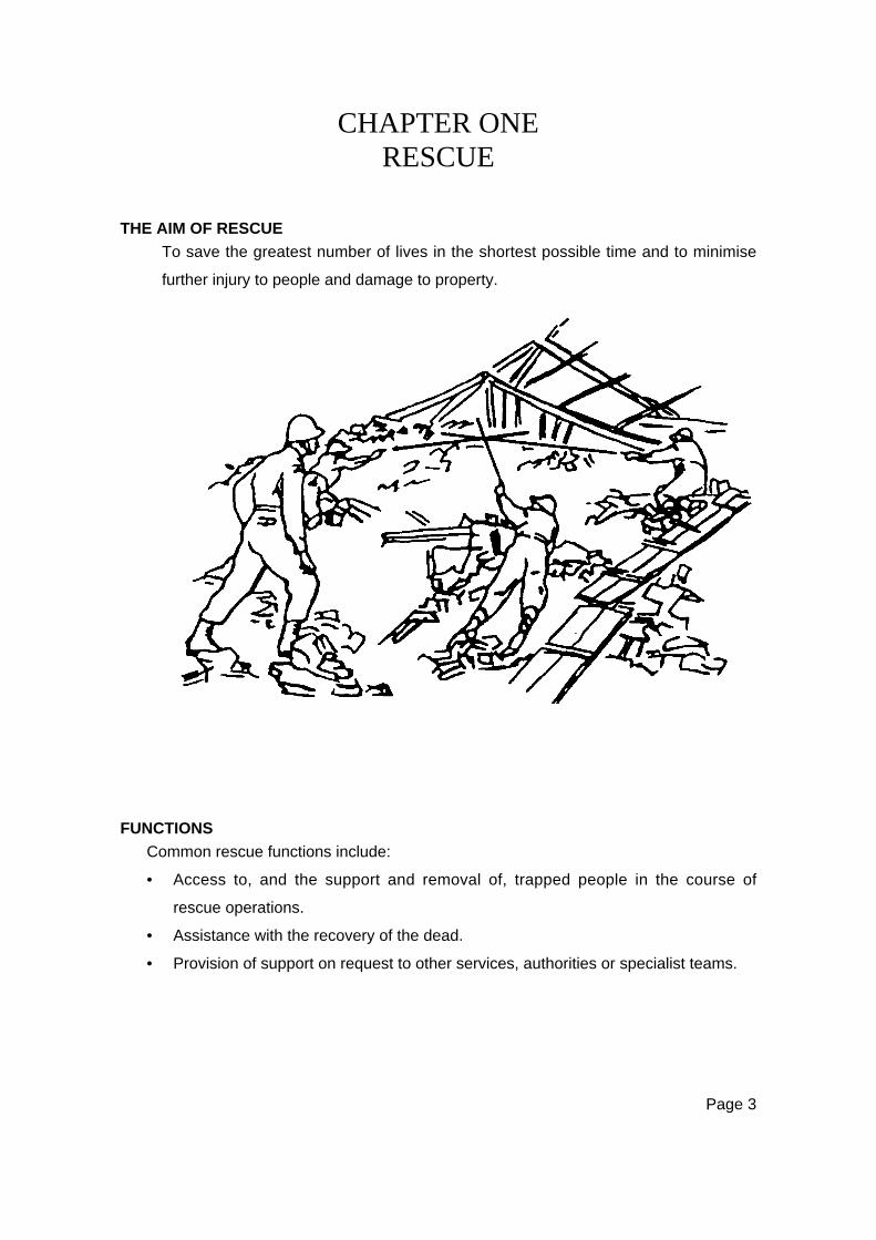
CHAPTER ONERESCUE
THE AIM OF RESCUE
To save the greatest number of lives in the shortest possible time and to minimise
further injury to people and damage to property.
FUNCTIONS
Common rescue functions include:
• Access to, and the support and removal of, trapped people in the course of
rescue operations.
• Assistance with the recovery of the dead.
• Provision of support on request to other services, authorities or specialist teams.
Page 4
WARNING NOTE:
In order to achieve the aim of rescue, all rescuers must be trained in
basic life sustaining first aid to recognised standards.
THE PSYCHOLOGY OF RESCUE
A moments reflection is all that is needed to realise that any situation requiring a
rescue operation, by definition is one which contains either dangerous or
potentially dangerous elements.
People tend to react differently to danger, but the most general responses are
anxiety and fear, perhaps the most powerful of all emotions. It must be
remembered that is not just the victim who faces the danger; in order to rescue the
victim the rescuer must first enter the site of the dangerous situation and face the
same danger. Even if the main danger has struck and passed, additional dangers
are still often present. The difference between the victim and the rescuer is that
the rescuer is better able to cope with, or handle, the situation. This is because
the rescuer has the knowledge and the resources to minimise risk and remedy the
situation.
It is normal to be anxious and feel fear in the face of danger. These are emotional
reactions common to both victim and rescuer. Many other emotional responses
may become manifest during a rescue situation—pity, disgust, contempt, pride,
concern, and many more. These are often exaggerated beyond all reason by the
urgency and pressures of the situation, thus lowering the efficiency of the overall
operation.
The rescuer must be aware of the psychological needs of the victims, not just their
physical needs, and be prepared to meet these psychological needs.

Page 5
RESCUE WORKERS
An event requiring rescue operations will usually create three categories of rescue
workers:
Group 1 – SurvivorsThe immediate reaction of survivors in a major incident, once they have discovered
that they are not injured, is to help their neighbours and families. They often do
not know what to do, but obviously it is a serious situation and thus they feel they
must do something.
These good intentions could aggravate the conditions of those being ‘helped’ to
the point where the loss of life may be greater than it should be. They could also
get in the way and interrupt the functioning of trained rescue teams. However,
uninjured and slightly injured survivors could well be the only hope of survival for
many victims (e.g. if toxic gases, dangerous chemicals, fire, or danger of fire exist
at the site of the emergency). The first group to commence rescue work at a site
consists of those survivors still physically capable of doing so. The potential for
good is enormous but the danger inherent in rescue work by untrained personnel
is also enormous.
Group 2 – Untrained PersonnelThe second ‘wave’ of rescue workers is drawn from people either witnessing the
event from the immediate vicinity, or are drawn to the site by curiosity and a desire
to assist the victims. Although not quite as emotionally involved as the survivors,
the danger inherent in utilising untrained personnel is still a factor which must be
considered. On the positive side, they often bring necessary resources with them
and can be effective if brought under control and properly supervised.
Unfortunately, a large number of the ‘curious’ are just that. They have no desire
to help, but just look. They get in the way, shout advice, and generally add to the
excitement of the site – the very thing that is least needed, especially from the
standpoint of victims.
Page 6
Group 3 – Trained PersonnelThe last group to arrive at the scene is the trained rescuers: Police, Fire, Civil
Defence, etc. It takes some time for various emergency services to mobilise and
arrive at the scene. The quicker they can arrive, the less time there will have
been for the first two groups to aggravate the situation and create more dangers to
surviving victims and themselves. The well-trained team will know what to do, and
how to utilise the available resources and untrained personnel in efficiently
carrying out the necessary tasks in a manner that will not further endanger anyone.
PERSONAL TRAITS OF THE RESCUER
Rescue work is not an easy task, nor is it necessarily a ‘glamorous’ one.
Certainly, not all people are suited to such work. Physical fitness, personality, and
emotional stability are all factors in determining one’s suitability.
Ideally, the rescuer will have the following qualities:
• Interest—A genuine interest in rescue work, not just because of peer
pressure, trying to impress, etc.
• Training—The will to continually undergo training to maintain a professional
standard.
• Cooperation—Rescue work is usually a team effort, hence cooperation with
others is vital.
• Dependability—The lives of victims, and team members rely on you.
• Initiative—The nature of rescue operations is such that it is often impossible to
closely supervise each team member. Each must be able to see what needs
doing, set priorities, and do the tasks at hand.
• Versatility—Each situation is unique. An individual must be able to apply a
wide range of skills and knowledge to new situations.
• Physical Fitness—Rescue work of any kind is physically demanding and often
continues for long periods. Any physical limitations must be recognised and
taken into consideration.
• Leadership Qualities—Required by all rescuers at various times and to
varying degrees. Through the capable leadership of trained rescuers, many
more untrained personnel may be utilised.

Page 7
• Control over Fears and Phobias—It is important that rescuers know what
they can and cannot do. Part of this knowledge consists of being aware of
any phobias. It is also vital that the leader of a rescue team knows of any
phobias in team members. Some phobias that could seriously affect a rescuer
and which may be identified in training are:
− The sight of blood (Hemophobia
− The fear of heights (Acrophobia)
− The fear confined spaces (Claustrophobia)
− The fear of water (Hydrophobia)
• Good Dress and Bearing—Appearance should instil confidence in others.
PERSONAL BEHAVIOUR
The conduct of individuals says a lot about their psychological makeup and
personality. The nature of rescue work is such that it is particularly important that
personal conduct does not aggravate matters, but rather assists in creating a
feeling that the situation is in competent hands, and everything possible is being
done to rescue and care for the victims.
A few of the more important general areas of conduct or behaviours follow:
• Attitude—A serious, professional attitude must be maintained to gain
confidence and support. Arrogance and superiority create instant antagonism.
Loud talking, joking, and horseplay reduce credibility; they create a feeling of
resentment and disgust and add to the confusion, thus hindering the work and
adding to the state of anxiety of the victims. Rescuers cannot consider
themselves ‘professional’ if they add to the confusion by loud shouting or
frantic gestures.
• Emotions—Emotions are hard to control in the best of circumstances. In a
disaster the control of emotions is a very difficult task but every effort must be
made to prevent emotions from influencing good judgement and competence.
Regardless of the excitement and the severity of the incident the rescuer must
be able to remain calm, and be sympathetic without becoming emotionally
involved.
Page 8
• Courtesy—Courtesy, tact, and good judgement are vital if the rescue task is to
be completed quickly and effectively. Courtesy must be given to all
concerned.
• Confidentiality—During rescue activities and training there may be times
when you will see and hear things which will be deemed confidential. It is
essential that you appreciate this and be ‘professional’ and do not discuss
these matters inappropriately.
TEAM COMPOSITION
Team composition will be determined by the various organisations within each
area on the basis of safe accomplishment of set tasks. Regardless of the team
composition, a team leader must be appointed. A team of 6 – 8 members is
required for effective general rescue teamwork.
ACTIVATION
Each team should have a callout system established, and have determined the
time necessary to ensure a full team response. This system should include such
details as:
• Who calls out the team
• Who will be responsible for them
• Where to report
• What functions the team will perform
• What equipment to take
• Likely duration of task or event.
Where possible, rescue team members should not be members of like
organisations or Emergency Services. If there is likely to be a conflict of interest
between organisations, rescue team members need to determine their priorities
and ensure that the Civil Defence Emergency Management Organisation is aware
of this.

Page 9
DEPLOYMENT
• On call-out, teams should state clearly to the organisation requesting their
support, details of accommodation and any feeding assistance that may be
required.
• If practicable, each team should be self-sufficient in the provision of food for
the first 24 hours.
COORDINATED INCIDENT MANAGEMENT SYSTEM
CIMS (the Coordinated Incident Management System) provides the model for
command, control, and coordination of an emergency response. It provides a
means of coordinating the efforts of agencies as they work towards the common
goal of stabilising an incident and protecting life, property, and the environment.
This is a separate course in its own right. For further information refer to the
Coordinated Incident Management System (CIMS) Manual – Teamwork in
E m e r g e n c y M a n a g e m e n t .

Page 11
CHAPTER TWOSAFETY IN TRAINING AND OPERATIONS
INTRODUCTION
The task of rescue involves the training of individuals and teams in a variety of
skills, some of which, unless properly carried out, may well prove dangerous to the
individual rescuer, the team, casualties, or bystanders. In all cases, the safety of
rescuers is of prime importance.
It is therefore necessary, particularly in the early stages of training and exercises,
to pay a great deal of attention to safety measures, and to emphasise the need to
strictly observe and enforce these measures.
WARNING NOTE:
All rescue training and operations must be carried out with due regard
to safe work practices, occupational health and safety requirements,
and codes of practice and guidelines.
Many of the safety precautions to be observed are merely common sense.
Unfortunately, they are so basic and simple they are often overlooked.
THE RESPONSIBILITY FOR SAFETY
Safety is the principal consideration in any rescue activity and it is the
responsibility of each rescuer to ensure that safety procedures and Occupational
Health and Safety requirements are followed, instructions observed, and
operations carried out with a minimum of risk.
There are a number of guidelines, codes of practice, regulations, and procedures
that relate to safety, and to operational aspects such as critical incident stress, and
risk management. These are constantly being amended and updated – it is the
responsibility of organisations to keep current.

Page 12
Additionally, individual services have procedures for the management of these
factors, and for laying out individual and organisational responsibilities. All of
these factors must be taken into account in the management of rescue activities.
This section covers the key points of safety in training and operations as they
affect the rescuer, the casualty, or the bystander. Specific safety points will be
covered with each rescue technique, as they affect the conduct of that rescue
technique.
BASIC PRECAUTIONS
Safety Officers should be appointed for any rescue activity. Team Leaders and
Safety Officers are responsible for safety at all times. The orders given by these
officers are to be obeyed without question or delay, as they are vital to safety.
Equipment must be regularly and carefully checked both before and after use.
Ropes can wear and rot, batteries can corrode equipment, and machinery can
break down. Faulty equipment can cost lives.
Any faulty or suspect equipment must be labelled immediately and removed for
repair or replacement (e.g. the rope that a rescuer used, but did not check, and
was damaged; may kill someone next time it is used).
Personnel ‘at risk’ by working at heights or depths must be protected by properly
established and monitored safety lines and systems.
Wherever possible, rescuers should adhere to standard techniques and practices.
In any rescue technique, safety limits and margins have been built in for casualty
and rescuer protection. These must never be ignored or exceeded.

Page 13
WARNING NOTE:
Under no circumstances is smoking permitted in the rescue environment.
Protective clothing and helmets are issued to each rescuer. Each has an obvious
safety application, and they must be properly used.
Helmets, in particular, must be worn at all times of risk, whether great or small.
They are designed to protect the wearer from a single impact, then be replaced.
They must never be mistreated by dropping, throwing, or being sat on. They
should never be exposed to the effects of UV for prolonged periods (e.g. by being
left on the back window-ledge of cars, or any other place).
All safety equipment must be maintained and replaced in accordance with the
manufacturer’s recommendations.
For training and operations, other items such as protective clothing, foul weather
gear, debris gloves, safety goggles, ear protection, and safety harnesses may be
issued. These are all for specific purposes, and must be treated and issued with
utmost care.
RESCUE / SAFETY HARNESSES
Personnel working at heights or in similar dangerous environments may require
the protection and safety of a harness. A properly fitted climbing, rescue, or
safety harness is recommended, and waist belts or safety lines are a minimum
requirement if harnesses are not available. A certified Karabiner should be used
for harness attachment with the rope or strop secured to the harness by this device
at an approved point.
Some industrial safety harnesses are not suitable for rescue, as the location of the
attachment points may be not suitable for rescue techniques. They are however,
Page 14
acceptable for low risk static situations. Competent advice should be obtained
before their purchase and use is required.
CASUALTY SAFETY
It must be obvious that the safety of casualties is important. Every effort including
the use of protective equipment must be made to ensure that casualties come to
no further harm once a rescue team arrives at the scene.
WARNING NOTE:
Horseplay or casual handling of casualties is unsafe and must not be tolerated.
For the sake of realism in training it is an advantage to use live casualties in
exercises and drills. Teams should bear in mind the added safety required when
dealing with heights, water, and contaminated areas, where dummy casualties
may be substituted. In most cases, it is only by handling live casualties in training
and exercises that rescuers will appreciate the problems they will encounter on
operations.
SAFE WORKING IN A CONFINED SPACE
WARNING NOTE:
Activities in a confined space must only be undertaken by appropriately trained
and qualified personnel.
In rescue operations, many environments may fall within the definition of confined
spaces as laid down in Standard AS/2865:1995 (Safe Work in Confined Spaces).
A confined space is defined as an enclosed or partially enclosed space which:
• Is at atmospheric pressure during occupancy

Page 15
• Is not intended or designed primarily as a place of work
• May have restricted means for entry and exit
• May have an atmosphere which contains potentially harmful levels of
contaminant
• Does not have a safe oxygen level
• May cause you to be buried.
Rescue activities in such environments must be carried out with particular regard
to the problems of breathing in dangerous atmospheres.
Page 16
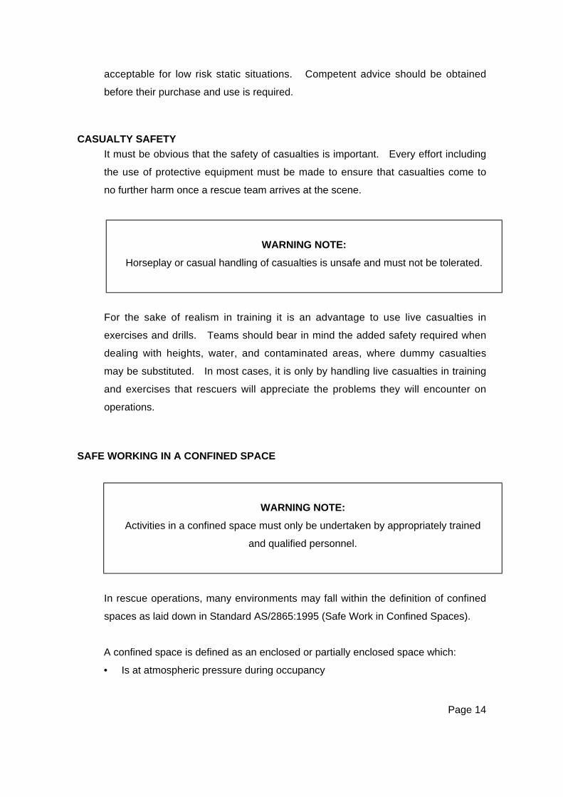
MOVING IN AN UNKNOWN ENVIRONMENT
When in strange surroundings and unable to see, the safest course of action is to
work by touch. The need for caution is obvious and accidents can be avoided by
remembering a few simple points:
The procedure for opening an outward opening door
when there may be fire on the other side.
The procedure for opening an inward opening door when
there may be fire on the other side.
While entering or leaving a smoke-filled room, crawl on
your hands and knees. In this position you are below
dangerous heated gases and the bulk of the smoke.
You will also be above toxic, heavier-than-air gases that
may have been generated by burning plastics and
natural materials.
Moving along a smoke-filled passageway in this manner
avoids lighter-than-smoke and heavier-than-air gases.
Page 17
.
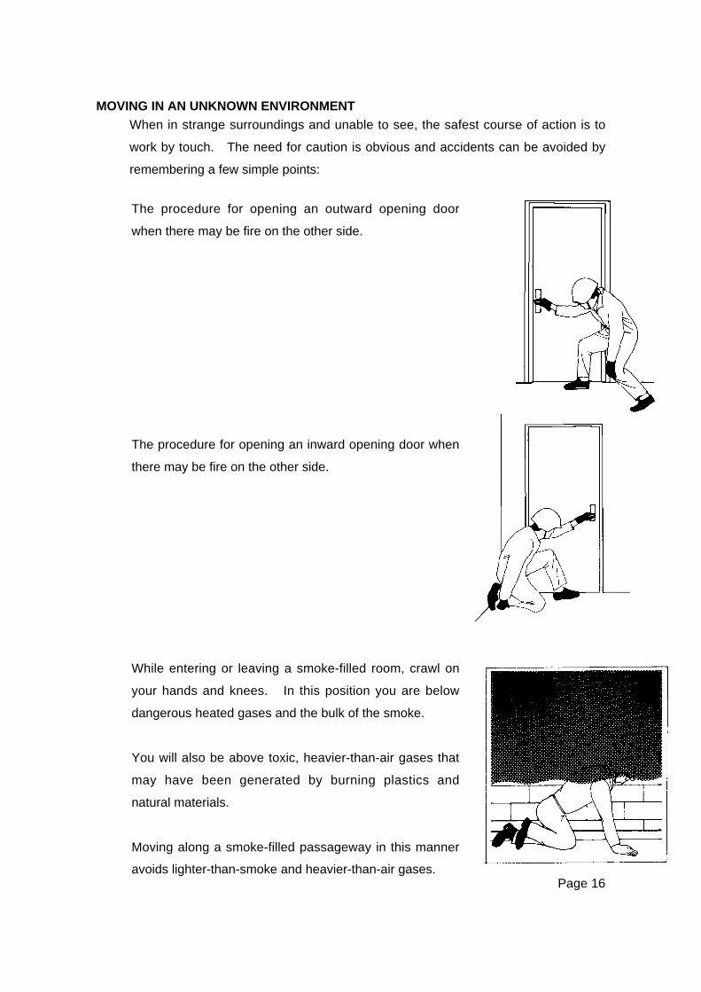
If you suspect fire is behind the door into a room, checkthe temperature of the door with the back of your hand.
If it is hot to touch, do not open the door, as the
temperature inside is excessive.
Shuffle, don’t walk. The weight of the body should be
kept poised on the rear foot until the advancing foot has
tested that it is safe to move forward; do not lift the feet
from the ground – they should slide forward as this will
help detect obstructions and dangers.
As you move forward raise your free hand in front of
your face, lightly clenched, with the back uppermost, to
feel for obstructions. If the back of your hand touches
a live electric wire, shock will throw it clear. Your hand
will not grasp the wire as it would if it were open.
When ascending or descending stairs, keep close to the
wall, since the treads will usually bear weight at this
point even though their centres may be weakened. If
there is any doubt as to their strength, allow only one
person on each flight at any one time. The balustrade
should be used with caution; it may have been
weakened and may collapse if any weight is applied to
it. If a stairway has been seriously damaged, use
sections of extension ladders to improvise a stairway.
Page 18
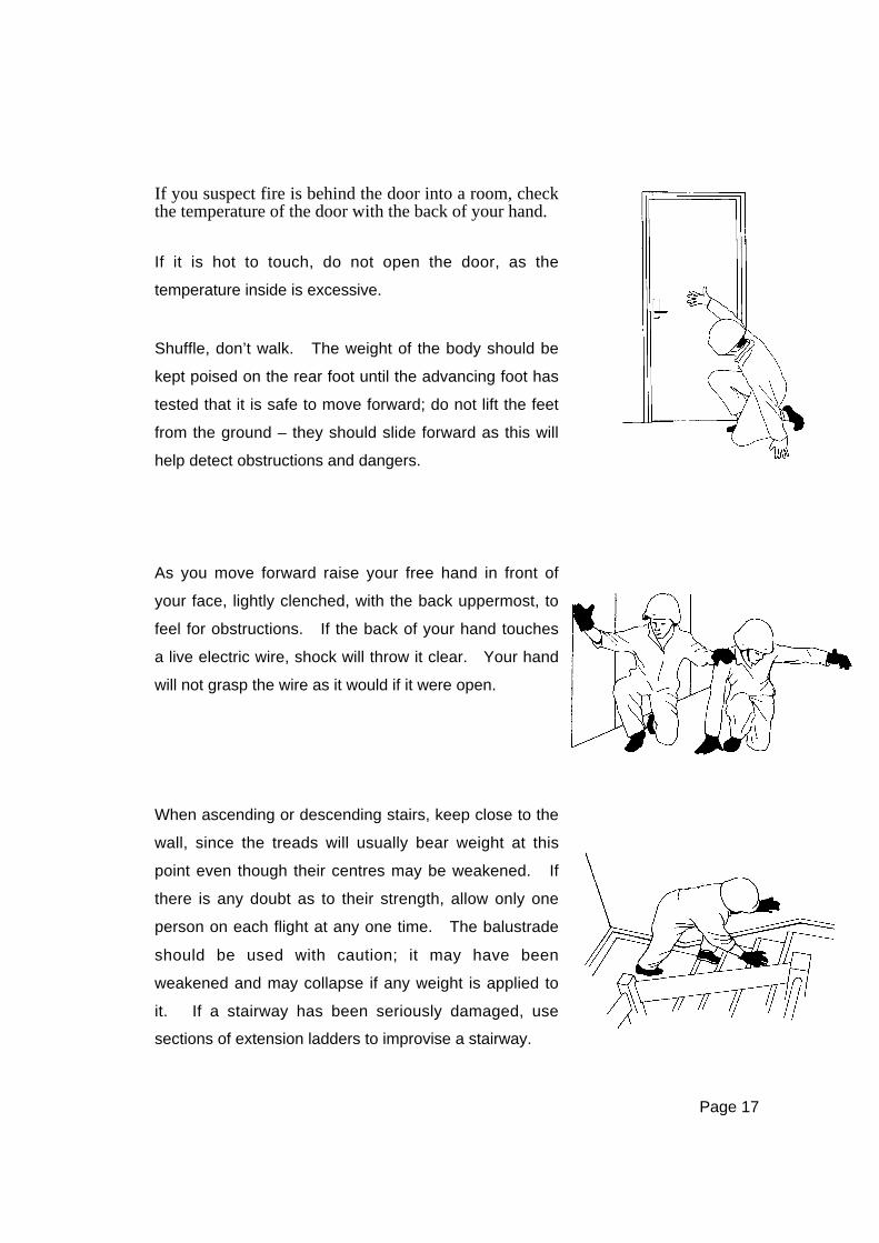
SEARCHING A DARKENED ROOM
• If a complete circuit is made in this way, in an average sized room, there should
be little danger of a victim being missed.
• As a final precaution, the room should be crossed diagonally to make sure that
no-one is lying in the centre.
• In a larger open-plan area (office, etc.), adopt this method with diagonals to the
centre of the room from each corner. Partitions and furniture will also hamper
movement.
VEHICLE SAFETY
Emergency vehicles must be driven by an authorised driver in accordance with the
Road Transport Act, particularly with regard to the use of warning lights and sirens.
Vehicles and trailers must be maintained in first class condition, and regular
checks and inspections should be routine.
Upon arrival at an accident scene, the rescue vehicle must be positioned with due
regard to the site hazards, and warning devices must be used to protect the team
and the vehicle.
The aim of a rescue team is to assist the public in time of need, and this should
always be kept in mind when the team is travelling to an emergency. Little can be
done for original casualties if the rescue team is involved in an accident en-route.
• Make a complete circuit
of the room, keeping
close to the wall.
• Feel under, and on,
objects (beds, etc).
• Open and feel inside
cupboards, wardrobes,
divans, and below other
pieces of furniture.

Page 19
EQUIPMENT SAFETY
All equipment should be used in close compliance with the manufacturers’
operating instructions, and the following basic safety rules for rescue tools and
equipment should be followed:
• Safety goggles and gloves must be worn when using power tools or hammering
pickets.
• Many items of equipment have been specifically designed for particular tasks.
Careful safety consideration must be given before any modification of
equipment, or method of use, is attempted.
• Only blades, fuel, oil, hydraulic fluid, and parts that are recommended by the
manufacturer should be used.
• Petrol driven motors must never be refuelled while they are hot, and they must
be kept apart from fuel supplies and casualties.
• All specific safety procedures for rescue equipment must be adhered to, and
regular and careful safety checks must be carried out both before and after
use.
PUBLIC UTILITY HAZARDS
GeneralAny emergency, from a vehicle accident to a disaster, can result in the rupture of
gas and water services, or the bringing down of electrical power lines.
All utility services must be treated with the utmost care, and where possible, either
the casualty removed from the source of danger, or the danger removed from the
proximity of the casualty.
In a disaster, rescuers must consider their own safety as more important than any
single casualty. The loss of a single rescuer could well affect the capability of the
team to conduct an effective rescue and save a large number of lives. This must
be weighed against the dangers involved in tackling a hazardous situation.
Page 20
Gas (CNG and LPG)Escaping gas creates the danger of explosion and the following safety precautions
must be observed:
• When entering a building, if you smell gas, turn off the supply and allow time
for the area to clear. Ventilation will greatly assist this.
• Never look for a leak with a match. Use soapy water, and if you find a leak,
turn off the supply immediately.
• Be extremely careful of leaking liquid propane or butane. Serious frostbite
burns will occur on contact with the liquid.
• If a cylinder is leaking liquid while lying on it’s side, stand the cylinder upright
before turning the cylinder off.
• If a line is broken and the supply cannot be turned off, the line can be crimped
with a pair of pliers.
• A leak that cannot be turned off can often be stopped by binding the area with
a wet cloth. This will freeze over and temporarily prevent any further leak.
Use thick gloves when attempting this.
• If it is not possible to stop the cylinder leaking, remove it to a safe place
outdoors, keeping people and ignition sources at least 20 metres away.
• If fire is present around a cylinder, keep the cylinder cool by hosing it with a
water spray.
• If a cylinder valve cannot be closed and the gas is burning, keep the cylinder
cool by hosing, but do not attempt to extinguish the flame as the build-up of
burned gases may explode if re-ignited.
• Never attempt to ignite a gas leak.
• Only intrinsically safe equipment should be used where gas is suspected.
• Never use power tools or oxy-acetylene torches in a confined area where gas
is suspected.
WaterWater from broken mains and other sources (e.g. rain, fire fighting water, etc.) may
enter areas where casualties could be trapped, especially in basement or other
underground areas. The appropriate precautions must be observed.
Page 21
SewersBroken sewers may create problems of flooding and escaping gas. Sewer gases
can be explosive as well as toxic. The following basic precautions must be
observed:
• Gas monitoring is essential for the safe handling of sewer gases.
• Take appropriate action prior to entering any area containing sewage.
• Never use an open flame.
• Endeavour to divert the flow away from the rescue area by building a dam or
other obstruction, or by pumping.
• Personal hygiene and public health issues must be addressed in the
appropriate manner.
ElectricityLive wires present a serious hazard to trapped casualties and rescue personnel,
therefore the following safety precautions should be observed at all times:
• Assume all electric wires are ‘live’. The fact that wires do not sputter or spark
is no indication that they are dead.
• Avoid pools of water close to live wires as they may be just as dangerous as
live wires.
• DO NOT attempt to cut any electrical wires.
• The supply to a damaged building should be switched off at the main switch,
normally located in the meter box. The fuses should be removed and
secured. Be aware; in some cases there may be more than one supply line to
an individual building.
WARNING NOTE:
Even when meter box switches are off and fuses are pulled, the building
will still be ‘live’ from the street supply to the meter box(es).
Expert assistance must be sought.
• Keep vehicles and personnel well clear of areas where wires are torn.
• Be particularly cautious at night when it is difficult to see wires. The technique
of holding the back of the hand out in front of your face is advised.
Page 22
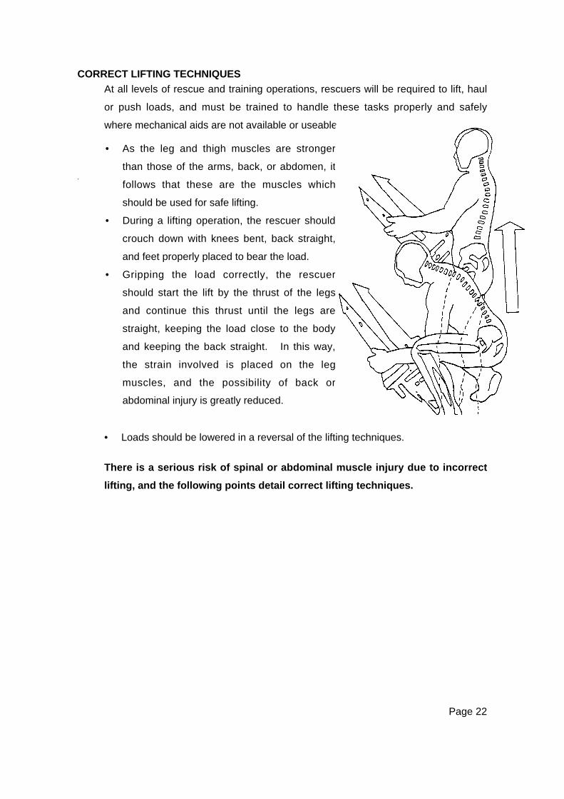
CORRECT LIFTING TECHNIQUES
At all levels of rescue and training operations, rescuers will be required to lift, haul
or push loads, and must be trained to handle these tasks properly and safely
where mechanical aids are not available or useable.
+
• Loads should be lowered in a reversal of the lifting techniques.
There is a serious risk of spinal or abdominal muscle injury due to incorrect
lifting, and the following points detail correct lifting techniques.
• As the leg and thigh muscles are stronger
than those of the arms, back, or abdomen, it
follows that these are the muscles which
should be used for safe lifting.
• During a lifting operation, the rescuer should
crouch down with knees bent, back straight,
and feet properly placed to bear the load.
• Gripping the load correctly, the rescuer
should start the lift by the thrust of the legs
and continue this thrust until the legs are
straight, keeping the load close to the body
and keeping the back straight. In this way,
the strain involved is placed on the leg
muscles, and the possibility of back or
abdominal injury is greatly reduced.

Page 23
TEAM LIFTING
Team lifting is carried out using the same individual techniques already described,
but with team discipline and control.
•••• When the team is in position with respect to the load, the leader gives the
preparatory order: PREPARE TO LIFT.
•••• Any rescuer not ready to lift must quickly call: STOP, and the Team Leader must
wait until all is in order. In the absence of any such dissent, the Team Leader will
give the executive order: LIFT.
• On this command, all rescuers lift their portion of the load by the technique
already described, slowly, and in unison.
•••• As with the individual technique, lowering a load is the reversal of the procedure
with the Team Leader using the commands: PREPARE TO LOWER and:
LOWER.

Page 25
CHAPTER THREERECONNAISSANCE
THE RESCUE PLAN
The success of rescue operations depends principally on the Team Leader
organising a quick and thorough reconnaissance of the situation, and then through
the appreciation process, developing a workable plan.
RECONNAISSANCE & RESCUE BY STAGES
No set of rules can be devised to give leaders specific guidance on how to tackle
every job, but by proceeding in stages in accordance with a regular plan they are
less liable to overlook important points and more likely to appreciate, and organise,
appropriate action.
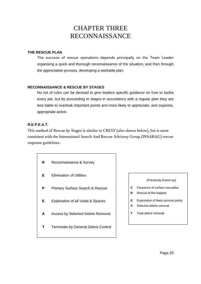
R.E.P.E.A.T.
This method of Rescue by Stages is similar to CREST (also shown below), but is more
consistent with the International Search And Rescue Advisory Group (INSARAG) rescue
response guidelines.
R Reconnaissance & Survey
E Elimination of Utilities(Previously known as)
P Primary Surface Search & Rescue C
R
Clearance of surface casualties
Rescue of the trapped
E Exploration of all Voids & Spaces E
S
Exploration of likely survival points
Selected debris removal
A Access by Selected Debris Removal T Total debris removal
T Terminate by General Debris Control
Page 26
Reconnaissance & SurveyThis is the initial activity undertaken upon arrival at a scene. It includes the resources
available to the Team, including personnel, equipment, local expertise, level of training,
size and complexity of task, etc. It also takes into account external factors including the
weather conditions, external and subsequent threats, structure, or building, in or near the
area, surface conditions, etc.
The assessment of the area, or site, that is searched for possible victims (surface
and/or buried) and the identification and evaluation of resources and hazards.
Information gained from this activity should be used to compile a “master” rescue plan of
the area or site, where victims, hazards, access, egress, etc. are shown.
Reconnaissance is an ongoing activity, and is not completed until the operation is
finished. Reconnaissance is:
C Continuous
A Accurate
R Rapid, and
T Thorough.
It is essential that every member of a rescue team be trained in reconnaissance.
In many instances the Team Leader will be responsible for a number of tasks, and
personnel deployed must be capable of conducting reconnaissance and of
reporting observations.
All sources should be exploited to obtain information regarding casualties,
damage, and likely hazards.
The reconnaissance summary should be aimed at an accurate assessment of:
• The number and location of casualties
• Dangerous situations such as gas, electricity, overhanging walls, unsafe
structural components, or anything else which may endanger rescue personnel
or survivors
• Access to the casualties or task and alternate exits

Page 27
• The extent and type of damage
• Appropriate services and support agencies
• Available resources, both personnel and equipment
• The time the task would take with available resources.
Elimination of UtilitiesAll utilities must be evaluated and controlled for the safety of all those involved. It
does not involve any treatment to, or rescue of, victims, as the main need is for
information at this stage. (It is expected that some rescue activities will be taking
place simultaneously.)
Primary Surface Search & RescueSurface, and lightly trapped, victims should be removed as quickly, and safely, as
possible.
Extreme care must be taken during this phase to ensure that rescuers do not become
victims. It is at this stage that many of the techniques in this manual will be put to use.
Where a number of structures have to be searched, it is vital to adopt a disciplined
Priority Structure Assessment (PSA). Also the hazard marking system, and the search
marking system must be applied at this stage.
Exploration Of All Voids And SpacesAll voids and accessible spaces created as a result of the event must be explored for live
victims.
Audible call systems can be used during this phase, e.g. line and hail search technique (as
described in Urban Search And Rescue (USAR) Category 1, Awareness).
WARNING NOTE:
Only suitably trained dog units, or specially trained rescue personnel
should be used in ‘void’ and ‘space’ searches.
General Rescue personnel should only enter void spaces
If visual contact with outside personnel can be maintained.
Page 28
Access By Selected Debris RemovalThe use of special tools and/or techniques may be necessary after locating a victim. It
may be necessary to remove only certain obstructions to gain access to the victim.
Information gained from the reconnaissance can be helpful during this phase.
Local knowledge and/or expertise will assist in the identification of possible victim
location, and also areas where structural safety is a concern. Experts might include
building wardens, survivors, engineers, etc.
Areas that have been identified by search dogs, or the use of electronic search
equipment will be given priority at this stage.
It would be unusual for heavy equipment to be used during this phase.
Termination by General Debris RemovalThis is usually conducted after all known victims have been recovered and accounted for.
An exception would be when information indicates the possibility of other victims
located where a large amount of debris is obstructing operations. The decision to use
heavy equipment during this phase must be given serious consideration, especially when
there is a possibility that live victims are still in the debris.
THE APPRECIATION PROCESS
The appreciation process is a simple method of problem solving which is effective
in rescue situations. It involves the logical assessment of the situation, and the
reconnaissance, and results in the formation of the workable plan.
The appreciation process consists of six steps:
Step One – Define The ProblemThe problem to be solved, or task to be accomplished must be clearly defined.
The problem may be too large or complex to be easily tackled, and may be divided
into a number of manageable elements, each with a set aim.
Page 29
Step Two – State The AimThe aim is a clear statement of what the team has to achieve in order to solve the
problem. The aim must be clear, concise, achievable, and expressed in positive
terms. The aim will form the mission statement in an operational briefing and
should be as simple as: “To rescue the casualty from the bottom of the lift shaft”.
Step Three – Consider The FactorsFactors are points relevant to the problem that has to be solved. Some factors
that may have to be considered in an operational situation are:
• Number and location of casualties
• Time and space
• Topography
• Weather
• Available resources, both personnel and equipment
• Support requirements and availability
• Communications
• Logistics
• Priority of tasks.
Each factor will lead to one or more logical deductions, so that the leader should
be in a position to say: “If this is the case – then…”
Factors in an appreciation may be set out as in the following example:
Factor The casualty’s legs are trapped under a heavy steel
beam.
Deduction The rescue team must use cutting and lifting equipment
to free the casualty.
Each factor should be thoroughly examined and care should be taken not to
introduce irrelevant facts into the examination.
Step Four – Determine Courses OpenAll possible courses that will attain the aim and that are practical must be
considered in the ‘Courses Open’ segment. Only facts dealt with in the ‘Factors’
should be considered and no new material should be introduced at this stage.
Page 30
Step Five – Decide On Best CourseAt this stage, a choice must be made from one of the possible solutions developed
by the appreciation process. If more than one workable solution is produced and
the best course is not obvious, the following criteria should be applied to each:
• Risk — Which solution carries the least risk factor in its execution, or the
consequence of failure?
• Simplicity — Which is the simplest course?
• Time — If urgency is a factor, which course can be completed in the shortest
time?
• Economy — In the terms of resources, which solution imposes the least
demand?
Step Six – PlanThe plan will result from the choice of the best course open. That is, it will be the
best solution to the problem with the most advantages and the least
disadvantages. The plan must be simple, and it must relate directly to the aim.
When completed, the plan should be checked against the following test questions:
• Is the reasoning sound?
• Is it set out in a logical order?
• Is everything relevant to the problem?
• Has anything relevant been left out?
• Is it free of uncertainties or ambiguities?
• Is it accurate (positions, timings and so on)?
• Has the aim been kept in mind throughout?
• Can the plan achieve the aim?
CONTINUING ACTION
Having made decisions and deployed personnel, Team Leaders must ensure
reconnaissance is continued with a view to allocating priorities for the further
deployment of resources.
Rescuers deployed on a particular building, damaged by blast or natural causes,
should make careful observation of how that building has collapsed. The art of
rescue lies in being able to identify and exploit to the maximum, all debris
Page 31
formations such as voids etc, which can be used to facilitate access to casualties
once their whereabouts have been fixed by firm information or inference.
Attempt to locate and identify the parts of the building and especially those parts in
which casualties are reported to be. This will provide a rough idea where
casualties might be found in relation to the various parts of the damaged structure.
At times such as this, a leader will need to call upon all accumulated experience
and training and combine them with effective decision-making.
CALLING AND LISTENING TECHNIQUES
When it is known that people are still missing, and rescuers are confronted with a
major structural collapse, the casualties may be trapped within voids or survival
spaces formed by the collapsing building. A ‘Calling and Listening’ period should
be introduced — this has, in the past, saved many lives.
The leader places available team members at suitable vantage points around the
area where people may be trapped, and then calls: SILENCE, SILENCE FOR
RESCUE.
Each member, as directed by the leader calls: RESCUE TEAM HERE, CAN YOU
HEAR ME? while the other members listen intently for any reply. If none is heard
it is a good plan to tap on a wall, or on any gas or water pipe, beam etc. running
into the debris, all of which are good conductors of sound, and again listen for an
answer.
On hearing a reply, each listener points to the place from which a sound came,
thus ‘pin pointing’ the position. Once contact has been established with a trapped
person, it must be maintained.
At night this procedure is best done by pointing in the direction of sounds with
torches. Rescuers must not be affected by peer pressure and must point to where
they think the sound comes from.
Page 32
Specialist resources such as trained dogs, heat sensors, fibre optic probes,
acoustic locators and the like should be utilised where available.
If casualties are located, their recovery will entail removing debris according to:
• The location of the casualty
• The nature of their injuries (if known)
• The layout of the building
• The way in which the building has collapsed.
Where it is not possible to account for all missing people, it may be necessary to
strip the site methodically. When debris has been relocated, the pile should be
suitably marked.
DAMAGE TO BUILDINGS
The type of construction of a building gives some indication of how it may collapse,
as a result of a blast, cyclonic wind, or earthquake. Most structures will contain
voids or spaces in which trapped people could remain alive for relatively long
periods. To know where these safe places may be, it is necessary to know the
broad characteristics of construction types.

Page 33
TYPES OF BUILDINGS
Buildings can be grouped into categories by the methods and materials used in
their construction:
• Light timber framed
• Unreinforced masonry
• Reinforced concrete masonry (blockwork)
• Concrete tilt-up
• Reinforced concrete/structural steel.
Light Timber Framed• Low rise
• Typically residential or school buildings
• Includes brick veneers.
Unreinforced Masonry• Brick or stone construction prior to mid-1930’s
• Could have concrete or timber floors
• May or may not be strengthened with steel or concrete elements.
Reinforced Concrete Masonry (Blockwork)• Typically low-rise (up to 3 storeys)
• 1960’s onwards.
Concrete Tilt-Up• Typically industrial buildings, but also newer medium-rise residential buildings.
Reinforced Concrete/Structural Steel• Ranges of different structural bracing systems (wall panels, moment resisting
frames)
• Concrete floors
• All eras/ all sizes.
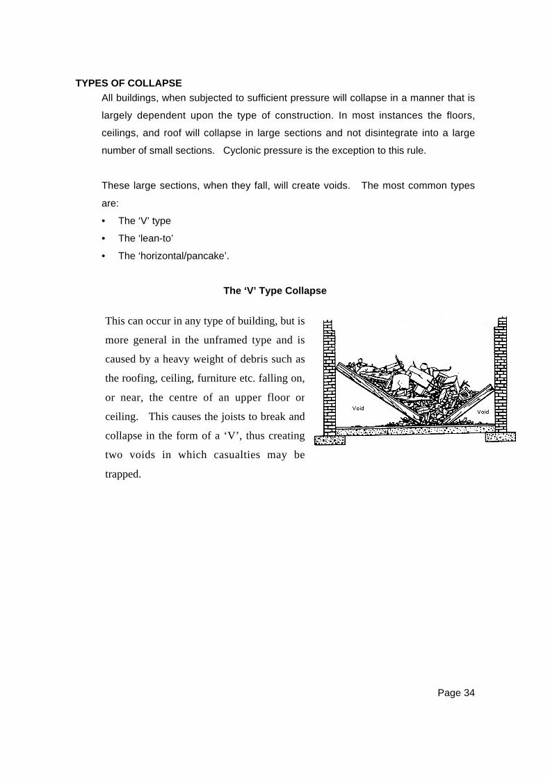
Page 34
TYPES OF COLLAPSE
All buildings, when subjected to sufficient pressure will collapse in a manner that is
largely dependent upon the type of construction. In most instances the floors,
ceilings, and roof will collapse in large sections and not disintegrate into a large
number of small sections. Cyclonic pressure is the exception to this rule.
These large sections, when they fall, will create voids. The most common types
are:
• The ‘V’ type
• The ‘lean-to’
• The ‘horizontal/pancake’.
The ‘V’ Type Collapse
This can occur in any type of building, but is
more general in the unframed type and is
caused by a heavy weight of debris such as
the roofing, ceiling, furniture etc. falling on,
or near, the centre of an upper floor or
ceiling. This causes the joists to break and
collapse in the form of a ‘V’, thus creating
two voids in which casualties may be
trapped.
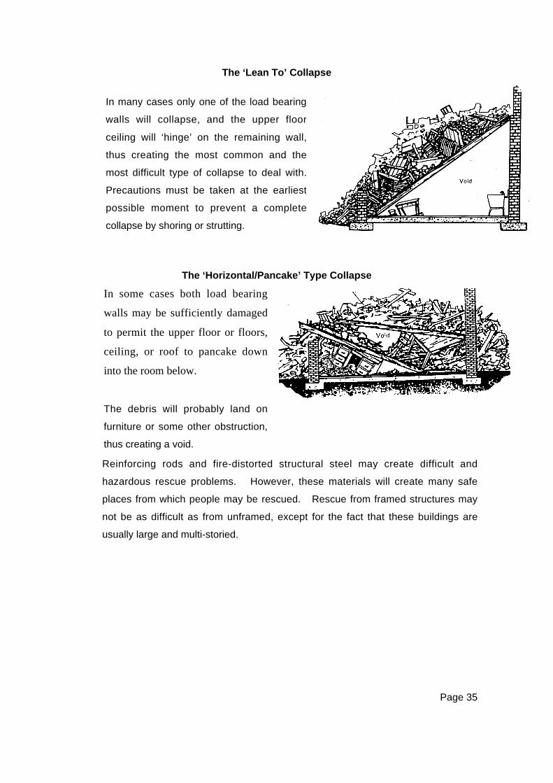
Page 35
The ‘Lean To’ Collapse
The ‘Horizontal/Pancake’ Type Collapse
Reinforcing rods and fire-distorted structural steel may create difficult and
hazardous rescue problems. However, these materials will create many safe
places from which people may be rescued. Rescue from framed structures may
not be as difficult as from unframed, except for the fact that these buildings are
usually large and multi-storied.
In many cases only one of the load bearing
walls will collapse, and the upper floor
ceiling will ‘hinge’ on the remaining wall,
thus creating the most common and the
most difficult type of collapse to deal with.
Precautions must be taken at the earliest
possible moment to prevent a complete
collapse by shoring or strutting.
In some cases both load bearing
walls may be sufficiently damaged
to permit the upper floor or floors,
ceiling, or roof to pancake down
into the room below.
The debris will probably land on
furniture or some other obstruction,
thus creating a void.
Page 36
PRECAUTIONS IN OPERATIONS
In the interest of safety to both the trapped and the rescuers, a thorough
appreciation must be made before any rescue operation is commenced. The main
safety considerations are as follows:
• Do not move any debris in contact with the collapse without assessing its
importance to the stability of the site.
• Always stabilise a collapse with shoring before entering a void.
• Entry and rescue procedures for confined spaces must comply with the
provisions of AS2865.
• Always appreciate the forces and their possible direction of movement in all
types of collapse.
• Pack and support vertically, horizontally, and laterally whenever and wherever
possible.
• In all materials used, consider their strength in relation to the loads to which
they will be subjected.
• Any disaster will invariably result in ruptured electrical water, gas, and sewer
lines and, although these will be primarily the responsibility of the public utility,
it is essential that rescue personnel be trained to deal with such problems in
the initial stages.
CRUSH INJURIES
It should be remembered that casualties may be found who have suffered severe
crush injuries. These people will be suffering from shock and their breathing
passages may be clogged by the dust contained in the debris. Rescuers must
take immediate steps to provide a clear airway for such casualties.
People trapped in debris and suffering from crush injuries need rapid and expert
medical attention. These victims should be treated, if possible, before release
from entrapment.
Page 37
DEBRIS CLEARANCE
Two methods by which people trapped under a pile of debris can be extracted are:
• By clearance of debris, ie: by removing the debris piece by piece until the
casualties are uncovered and freed.
• By the construction of tunnels and linking of voids.
If anyone survives at all, inside or under a large pile of debris after a building has
collapsed, it is because some heavy timber (a floor, or other portion of the
structure) has fallen or remained fixed, in such a way as to protect this person from
the main impact and weight of the debris. Furniture can sometimes protect a
casualty. Unless something of this kind has happened, it is unlikely that the
casualty will survive. This protection may be of a very unstable nature, and,
unless great care is exercised, it may collapse.
Internal collapse can be avoided only by disturbing the debris as little as possible
during rescue operations, and by making sure that, as one portion of the debris is
removed, the remainder is not dislodged and allowed to slide or fall.
Careful observance of these principles reduces the risk of further injury to trapped
people, resulting in greater speed in the rescue operation. The ideal is “speed
with safety”.
When Debris Clearance Is NecessaryIf no information is available regarding the approximate position of people trapped
in debris, rescue can usually be effected only by total debris clearance. The
essential difference between debris clearance as a rescue operation and debris
clearance to clear a site is that, so long as there is a reasonable chance of
recovering casualties by debris clearance, it must be proceeded with by rescue
teams with unremitting effort. Rescue services must continue at work until it is
certain that nobody is still alive, and that the responsible officer, according to local
arrangements, decides that operations can be discontinued.

Page 38
Methods Of Debris Clearance• When debris clearance is undertaken for rescue purposes, the debris should
be moved clear of the demolished building, and not merely from one part of the
site to another.
• Debris can be removed by hand or by using other receptacles found on the
site. In a confined space or over obstacles, it is best to form a human chain.
• It may sometimes be necessary when clearing debris, to cut a lane through it
to reach a casualty. Great care must be taken in so doing, to ensure that the
sides of the lane do not collapse. These can be made safe, where necessary,
by a simple form of timbering or strutting
Precautions In Operations• Exercise care in the use of edged tools in debris clearance.
• Debris close to casualties should always be removed by hand.
• Rescuers must wear gloves.
• Rescuers must not climb over debris during the clearing operation unless
absolutely necessary.
• Debris should be withdrawn only when it is certain that no further collapse will be
caused.
• Heavy equipment should be operated only at the direction of the officer in charge.
• Movement of major debris elements must be carefully coordinated.
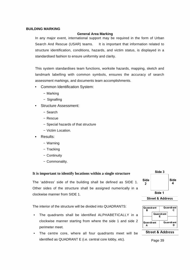
Page 39
BUILDING MARKING
General Area MarkingIn any major event, international support may be required in the form of Urban
Search And Rescue (USAR) teams. It is important that information related to
structure identification, conditions, hazards, and victim status, is displayed in a
standardised fashion to ensure uniformity and clarity.
This system standardises team functions, worksite hazards, mapping, sketch and
landmark labelling with common symbols, ensures the accuracy of search
assessment markings, and documents team accomplishments.
• Common Identification System:
− Marking
− Signalling
• Structure Assessment:
− Search
− Rescue
− Special hazards of that structure
− Victim Location.
•••• Results:
− Warning
− Tracking
− Continuity
− Commonality.
It is important to identify locations within a single structure
The ‘address’ side of the building shall be defined as SIDE 1.
Other sides of the structure shall be assigned numerically in a
clockwise manner from SIDE 1.
The interior of the structure will be divided into QUADRANTS:
• The quadrants shall be identified ALPHABETICALLY in a
clockwise manner starting from where the side 1 and side 2
perimeter meet.
• The centre core, where all four quadrants meet will be
identified as QUADRANT E (i.e. central core lobby, etc).
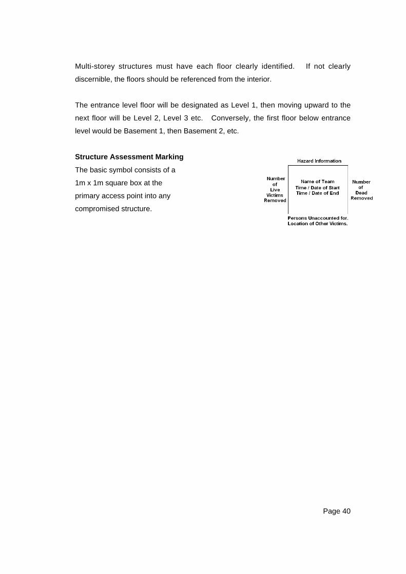
Page 40
Multi-storey structures must have each floor clearly identified. If not clearly
discernible, the floors should be referenced from the interior.
The entrance level floor will be designated as Level 1, then moving upward to the
next floor will be Level 2, Level 3 etc. Conversely, the first floor below entrance
level would be Basement 1, then Basement 2, etc.
Structure Assessment Marking
The basic symbol consists of a
1m x 1m square box at the
primary access point into any
compromised structure.

Page 41
Example Marking Box
Example Completed Marking Box
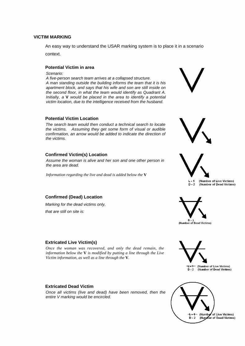
Page 42
VICTIM MARKING
An easy way to understand the USAR marking system is to place it in a scenario
context.
Potential Victim in area
Potential Victim Location
Confirmed Victim(s) Location
Confirmed (Dead) Location
Marking for the dead victims only,
that are still on site is:
Extricated Live Victim(s)
Extricated Dead Victim
Scenario:A five-person search team arrives at a collapsed structure.A man standing outside the building informs the team that it is hisapartment block, and says that his wife and son are still inside onthe second floor, in what the team would identify as Quadrant A.Initially, a V would be placed in the area to identify a potentialvictim location, due to the intelligence received from the husband.
The search team would then conduct a technical search to locatethe victims. Assuming they get some form of visual or audibleconfirmation, an arrow would be added to indicate the direction ofthe victims.
Assume the woman is alive and her son and one other person inthe area are dead.
Information regarding the live and dead is added below the V
Once the woman was recovered, and only the dead remain, theinformation below the V is modified by putting a line through the LiveVictim information, as well as a line through the V.
Once all victims (live and dead) have been removed, then theentire V marking would be encircled.
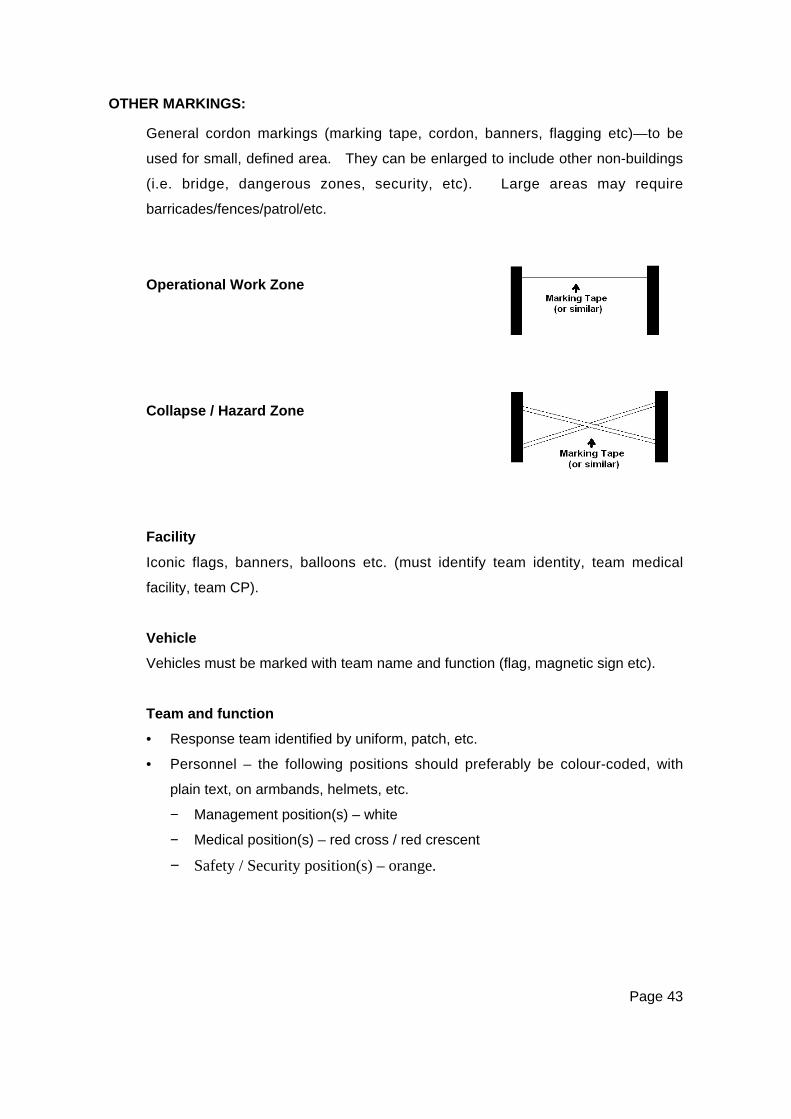
Page 43
OTHER MARKINGS:
General cordon markings (marking tape, cordon, banners, flagging etc)—to be
used for small, defined area. They can be enlarged to include other non-buildings
(i.e. bridge, dangerous zones, security, etc). Large areas may require
barricades/fences/patrol/etc.
Operational Work Zone
Collapse / Hazard Zone
Facility
Iconic flags, banners, balloons etc. (must identify team identity, team medical
facility, team CP).
Vehicle
Vehicles must be marked with team name and function (flag, magnetic sign etc).
Team and function
• Response team identified by uniform, patch, etc.
• Personnel – the following positions should preferably be colour-coded, with
plain text, on armbands, helmets, etc.
− Management position(s) – white
− Medical position(s) – red cross / red crescent
− Safety / Security position(s) – orange.
Page 44
THE DEAD
Identification And RemovalAlthough identification of the dead is a Police responsibility, routine procedures
may not be feasible in a major disaster. Police Disaster Victim Identification (DVI)
teams, located at various points around the country will be deployed to a disaster
area and may require Civil Defence Emergency Management assistance.
• In general, do not remove bodies from the position in which they were found
without the agreement of the Police.
• Nevertheless, a rescuer may be justified in moving a body:
− When rescuers would be put at risk if they had to re-enter the
damaged building or structure where the body is located.
− Where it is necessary in order to reach an injured person.
− Where the body itself might be affected by flooding, fire, or imminent
collapse of a building or structure.
• The exact position in which a body is found may be critical to the identification
of that person, particularly if there is extensive mutilation.
• Where bodies do not have to be removed from the building or structure for
reasons of safety, make a notebook entry of the location of the body and
advise the Police as soon as possible. If possible, do not leave the site until
the Police have arrived.
• Where, in the interests of safety, it is considered that bodies should be
removed from the exact location of where the body was found, then the
person finding the body must collect all necessary information (including any
identity obtained from survivors, and personal belongings found with the
body). This should be recorded and attached to the body.
Page 45
Suspicious Circumstances• If you are in any way suspicious as to the cause of death (suspecting either
murder or suicide), do not disturb the body and surrounding area, but record,
secure, and then notify the nearest Police.
• Where there is danger of further damage to the body, (by fire, flood, or
collapse of the building or structure, or danger to rescue workers and Police),
then the body may be removed to a safe place which can be secured.
• Give the Police all vital information (covering the location and position of the
body, cause of death, suspicions, circumstances, personal belongings, etc.)
included in a full report as soon as possible.
• Photographic records of the original position and surrounding area would be
most beneficial, where available.
Conduct At The Scene• In the presence of death, everyone should be respectful, subdued, and
orderly.
• There should be no attempt at humour.
• Although survivors may be shocked when seeing their relative or friend
covered, indicating death, DO cover a severely mutilated body.
• Otherwise, treat a body as you would a low priority casualty.

Page 47
CHAPTER FOURROPES, TAPES, KNOTS & LASHINGS –
GENERAL INFORMATION
INTRODUCTION
During a rescue operation, a variety of techniques involving ropes, tapes, knots
and lashings may be required.
IDENTIFICATION
A system of marking each end of a rope for identification of length, and with a
reference number to the rope history card, is recommended.
Colour Coding can be used to quickly identify ropes, and should be located at each
end of the rope. The suggested colour coding is:
• GREEN—OK to use for all activities.
• RED—not suitable for ‘life’ work.
Discard damaged rope immediately.
If faults are found during any rope inspection, immediate steps must be taken to
rectify the problem(s) in accordance with Standard—AS4142.3 (or EN1891).
RECORD SYSTEMS
All ropes should be clearly and permanently identified and a record kept of
individual items, their usage, inspection, and maintenance.
Suggested headings for a record system are as follows:
• Identity Number
• Item Description
• Purchase Date
• Usage Dates
•••• Description of Usage
• Inspection Date
Page 48
• Inspected By: (name)
• Maintenance Carried Out
• Signature.
ROPE
Rope is one of the most important tools of the rescue team. Rescuers will use a
range of rope types for specific applications. All types have their advantages and
disadvantages, but provided the rescuer has thorough knowledge of the
characteristics and capabilities of each type, all will give valuable service provided
they are appropriately cared for and maintained.
Whilst it is accepted that the Standard has not yet been adopted by all rescue
services, it is strongly recommended that only synthetic fibre, Kernmantel, and
static ropes which comply with AS4142.3, be used for life rescue purposes.
TYPES OF ROPE
The ropes in common use with rescue teams are:
• Synthetic fibre rope
• Climbing tape
• Natural fibre rope
• Flexible steel wire rope (SWR).
TERMINOLOGY
For the purpose of this manual, the following terms are used in reference to rope
and rope management. Other terms may be used in specific organisations.
AnchoringFastening a rope to some suitably secure object.
BelayingControlling a safety rope attached to personnel or equipment as a backup in case
of primary system failure.
BightA simple bend in which the rope does not cross itself.
Page 49
Breaking ForceThe averaged ultimate breaking point of rope.
Expressed in kilograms (kg) or in kilo-Newtons (kN) following rigorous testing.
Also referred to as Breaking Strain or Mean Breaking Load.
HaulingThe act of pulling on a rope.
Half-HitchThe closed loop on a rope; a simple fastening of a rope around some object by
winding and crossing one turn so that one section of the rope bites on the other
without actually knotting the rope.
KernmantelA style of construction of synthetic fibre rope, consisting of a core (kern) and a
sheath (mantel).
LoopA simple bend in which the rope crosses itself.
MarryingTwisting the running end around the standing part, in the same direction as the lay
of the rope.
MousingTying a piece of cord or wire across the jaws of a hook to prevent a rope or sling
from jumping out of the hook.
Parcelling / Edge ProtectionWrapping a section of the rope to prevent chafing against some object.
Paying Out / EasingReducing the tension on a rope so as to allow it to pay out or slacken.
ReevingThreading a rope through pulley blocks.
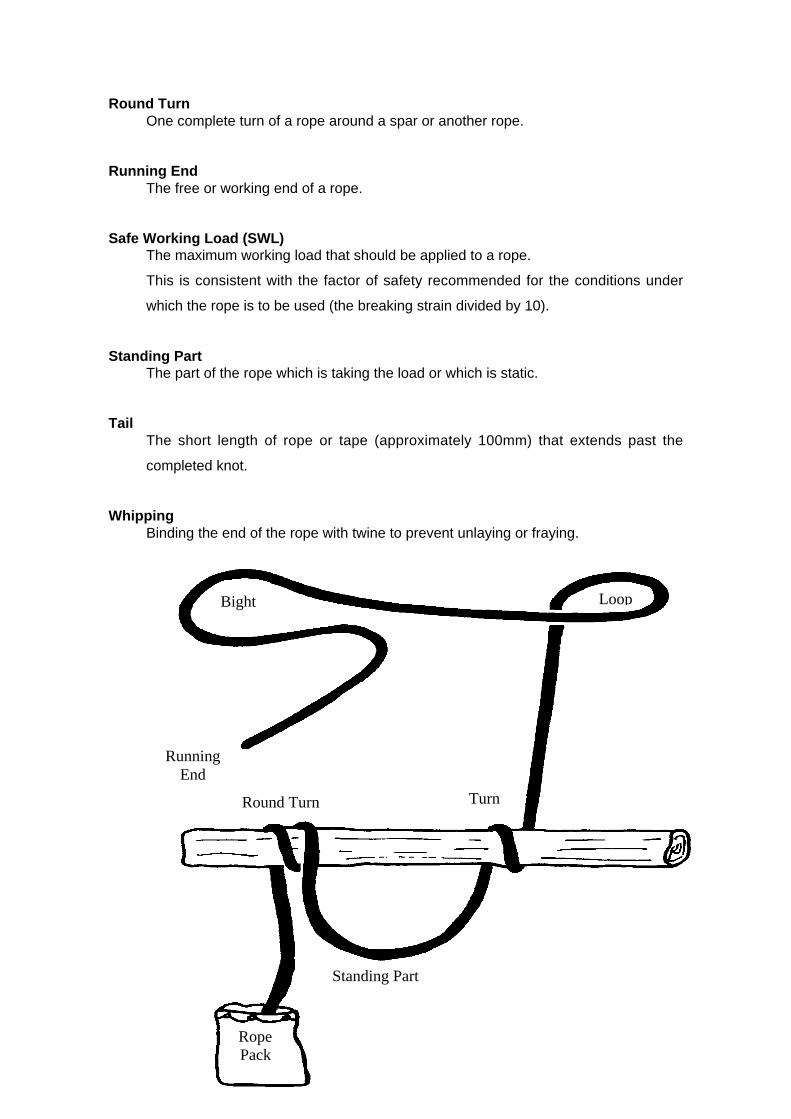
Page 50
Round TurnOne complete turn of a rope around a spar or another rope.
Running EndThe free or working end of a rope.
Safe Working Load (SWL)The maximum working load that should be applied to a rope.
This is consistent with the factor of safety recommended for the conditions under
which the rope is to be used (the breaking strain divided by 10).
Standing PartThe part of the rope which is taking the load or which is static.
TailThe short length of rope or tape (approximately 100mm) that extends past the
completed knot.
WhippingBinding the end of the rope with twine to prevent unlaying or fraying.
Bight Loop
RunningEnd
Round Turn Turn
Standing Part
RopePack

Page 51
ROPE PACKAGING
There are a number of techniques suited to the packaging of rescue ropes,
including:
•••• Stuff Sacks
•••• Chaining
• Hanking
• Coiling
Stuff SacksThese are the preferred method of storage and carriage for long length ropes, and
as the name implies, the rope is merely stuffed into the pack and gently tamped
down. The sacks can be simply bags, or packs with straps for carriage to the site,
and while they are expensive, rucksacks are best for most operations.
ChainingThis is a technique that can be used for ropes of any length,
which reduces the final length of the packaged rope. This is
useful when washing ropes in a washing machine or for
operational packaging. The rope can be chained as a single
length, or doubled and then re-doubled as shown.
Hanking the RopeThis is also effective for 50m or shorter lengths, and is quite
effective with doubled ropes.
• Grasp the rope about 2 metres from one end and at full
arm span distance, form bights in the rope, laying them on
alternate sides of your hand.
• Continue until 4 metres from the other end.
• Tie the next 2 metres around the bundle of rope just
beneath your hand working up towards your hand.

Page 52
• With the remaining 2 metres, push a bight through the
hole where your hand was (between where tied and the
doubled rope bight), invert it over the head of the hank
and pull tight.
To use, undo the bight and hold the hank
• Lay on ground
• Pull out as required.
CoilingRopes of up to 50m in length can be rapidly coiled and
finished off with turns. It should be noted that coiling will
severely kink a rope, and that hanking is preferred to coiling
at all times.
The coil can be secured as shown.
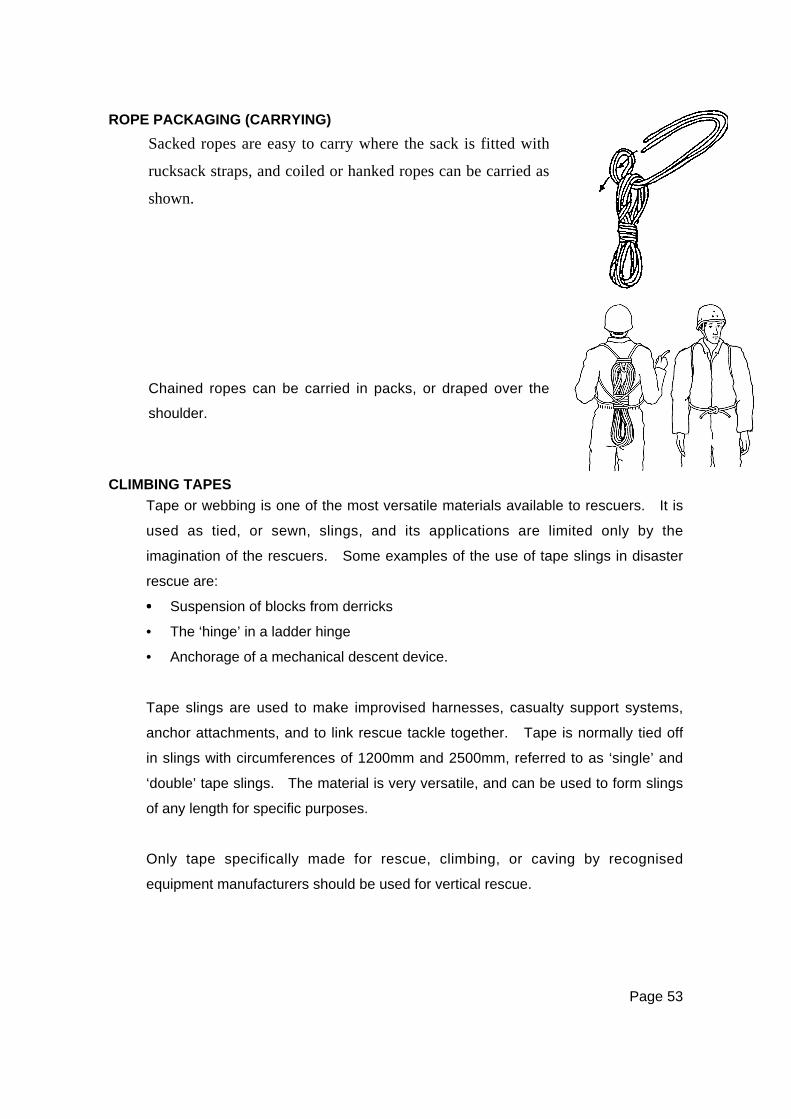
Page 53
ROPE PACKAGING (CARRYING)
CLIMBING TAPES
Tape or webbing is one of the most versatile materials available to rescuers. It is
used as tied, or sewn, slings, and its applications are limited only by the
imagination of the rescuers. Some examples of the use of tape slings in disaster
rescue are:
•••• Suspension of blocks from derricks
• The ‘hinge’ in a ladder hinge
• Anchorage of a mechanical descent device.
Tape slings are used to make improvised harnesses, casualty support systems,
anchor attachments, and to link rescue tackle together. Tape is normally tied off
in slings with circumferences of 1200mm and 2500mm, referred to as ‘single’ and
‘double’ tape slings. The material is very versatile, and can be used to form slings
of any length for specific purposes.
Only tape specifically made for rescue, climbing, or caving by recognised
equipment manufacturers should be used for vertical rescue.
Sacked ropes are easy to carry where the sack is fitted with
rucksack straps, and coiled or hanked ropes can be carried as
shown.
Chained ropes can be carried in packs, or draped over the
shoulder.
Page 54
ConstructionThere are two broad design categories of tape—flat and tubular. Both types are
actually flat in appearance. However, if tubular tape is viewed in cross section, it
forms a hollow tube. Standard tubular tape is normally the strongest and most
flexible form, and is therefore recommended for vertical rescue.
Tape is woven in many different ways, and the characteristics that can be effected
by the style of construction are: strength, elongation, abrasion resistance, and
ultra-violet resistance. All of these factors are affected by the fibre used and the
weave tension in particular. While a tape with a very tight weave will be strong,
knot retention and suppleness will be poor. Obviously, a good rescue tape is a
compromise of factors.
SizePolyamide is sized by a flat width, with 25mm and 50mm being the most
commonly used sizes. Smaller tape sizes may be used for some very specialised
techniques, but are not suitable or safe for general vertical rescue work.
AbrasionUnder certain circumstances, tape is liable to abrade or wear more rapidly than
rope, and it has no sheath for extra protection. Additional attention must be paid
to wear or friction areas, and tapes must be discarded when doubt exists as to its
safety.
Tape StrengthFor vertical rescue operations, only tape with a minimum rated strength of 1500kg
should be selected.
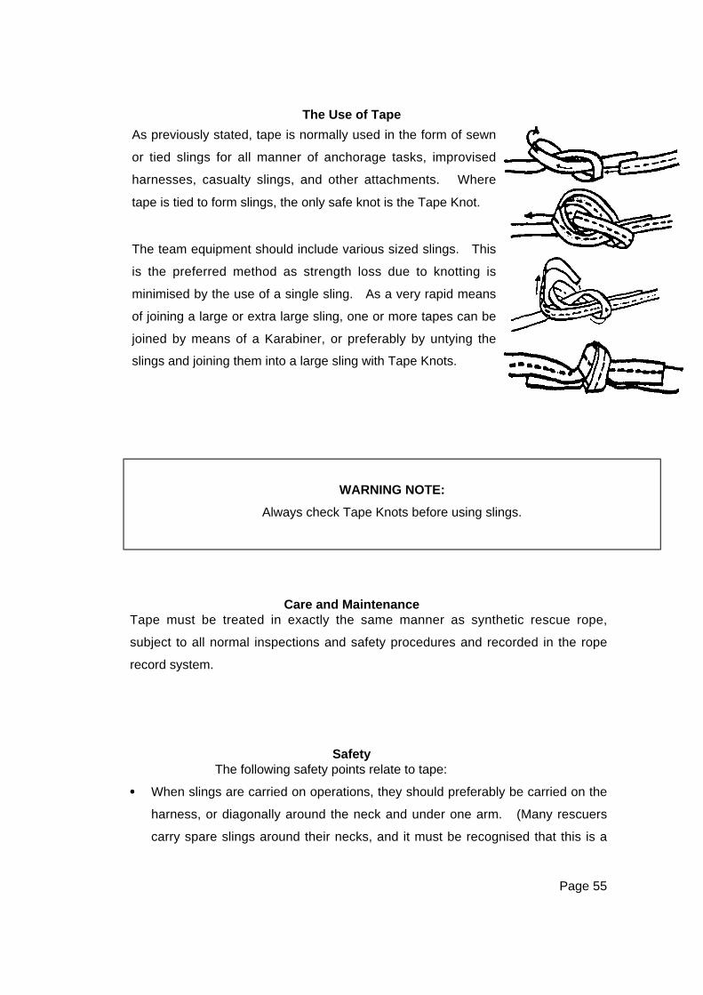
Page 55
The Use of Tape
WARNING NOTE:
Always check Tape Knots before using slings.
Care and MaintenanceTape must be treated in exactly the same manner as synthetic rescue rope,
subject to all normal inspections and safety procedures and recorded in the rope
record system.
SafetyThe following safety points relate to tape:
•••• When slings are carried on operations, they should preferably be carried on the
harness, or diagonally around the neck and under one arm. (Many rescuers
carry spare slings around their necks, and it must be recognised that this is a
As previously stated, tape is normally used in the form of sewn
or tied slings for all manner of anchorage tasks, improvised
harnesses, casualty slings, and other attachments. Where
tape is tied to form slings, the only safe knot is the Tape Knot.
The team equipment should include various sized slings. This
is the preferred method as strength loss due to knotting is
minimised by the use of a single sling. As a very rapid means
of joining a large or extra large sling, one or more tapes can be
joined by means of a Karabiner, or preferably by untying the
slings and joining them into a large sling with Tape Knots.
Page 56
potentially lethal practice; should the rescuer fall, the loose slings can snag,
resulting in serious or fatal injury.)
• Knots must be regularly checked for signs of overstrain or loosening, and
properly retied, or cut and retied, where necessary, with minimum tails of
100mm.
• All tape must be regularly and carefully inspected for signs of damage or
abrasion, and where damage is suspected, or serious abrasion has occurred,
the tape must be withdrawn from service. Where a sling has been subjected
to a severe loading, it may be seriously damaged but the damage may not be
obvious. ALL SUCH SLINGS MUST BE DESTROYED.
WARNING NOTE:
Home sewn slings are totally unsafe and have no place in the
rescue environment.
Tubular tape is preferred for rescue as it is less prone to damage on an edge or
rough area than is flat tape.
Tape must have the same care as rope. It should be protected from abrasion,
contamination, friction heat, and shock loading, and inspected before, during, and
after every use.
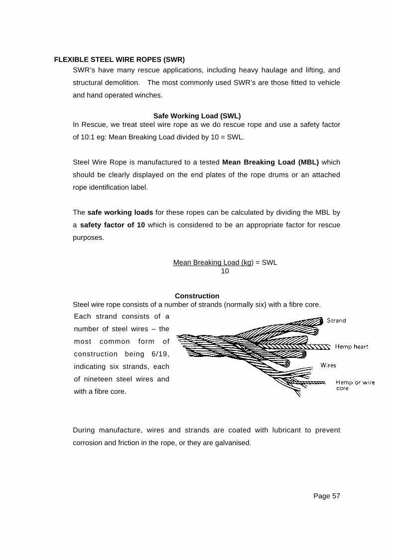
Page 57
FLEXIBLE STEEL WIRE ROPES (SWR)
SWR’s have many rescue applications, including heavy haulage and lifting, and
structural demolition. The most commonly used SWR’s are those fitted to vehicle
and hand operated winches.
Safe Working Load (SWL)In Rescue, we treat steel wire rope as we do rescue rope and use a safety factor
of 10:1 eg: Mean Breaking Load divided by 10 = SWL.
Steel Wire Rope is manufactured to a tested Mean Breaking Load (MBL) which
should be clearly displayed on the end plates of the rope drums or an attached
rope identification label.
The safe working loads for these ropes can be calculated by dividing the MBL by
a safety factor of 10 which is considered to be an appropriate factor for rescue
purposes.
Mean Breaking Load (kg) = SWL10
ConstructionSteel wire rope consists of a number of strands (normally six) with a fibre core.
During manufacture, wires and strands are coated with lubricant to prevent
corrosion and friction in the rope, or they are galvanised.
Each strand consists of a
number of steel wires – the
most common form of
construction being 6/19,
indicating six strands, each
of nineteen steel wires and
with a fibre core.
Page 58
Precautions in OperationsWire ropes should not be bent sharply at any point. As a general rule the smallest
diameter around which a SWR should be bent should be approximately ten times
the diameter of the rope – anything less than this will cause damaging and
uneven stresses on the rope: eg: 10mm rope needs a 100mm bend.
Inspection of Steel Wire RopeSWR’s should be regularly inspected in the following manner:
• Check the shackle used with the rope to see that it has not suffered distortion
or strain and that the shackle pin is in good condition; easily screwed home by
hand.
• Examine the thimble and the splice. The splicing cannot be seen as it is
covered by the wire binding or ‘serving’, but if the binding is loose or shows
signs of bulging, it is probable that the splice is starting to come undone.
• Wearing gloves, work along the rope, a hands breadth at a time, checking that
it is reasonably round, i.e. it has not been flattened or suffered distortion which
causes the wires to open and thus weaken the rope.
• Look for broken wires. A broken wire in a rope should always receive prompt
attention. Delay may lead to serious accidents and will certainly cause
damage to other wires. The method often used to deal with a broken wire,
nipping the wire off using pliers is not entirely safe as a small jagged end is left.
To save time and trouble, simply bend the wire backwards and forwards with
the fingers until it breaks, or, in the case of a short end, use a piece of wood to
bend the wire. In this way, the wire breaks inside, instead of outside the rope,
and the end is tucked away between the strands where it can do no harm.
• Look for kinks. When a rope has been kinked, the kink may pull, but when the
rope is stressed, and although it may appear reasonably sound, the structure
of the rope has been distorted and damaged. The length affected by the
kinking may only be small, but this becomes the weakest part of the rope. The
presence of a kink is best detected when the rope is lying slack on the ground.
Rope of any sort found defective should be labelled and placed apart from
good ropes until they can be examined by a competent person.

Page 59
Storage of Steel Wire RopesWire ropes should be stored under cover in a clean, dry place and in such a
manner that no part touches the ground. They must never be stored by laying on
concrete or other floors, as these have an adverse effect on the steel. Regular
inspection for the presence of corrosion is necessary.
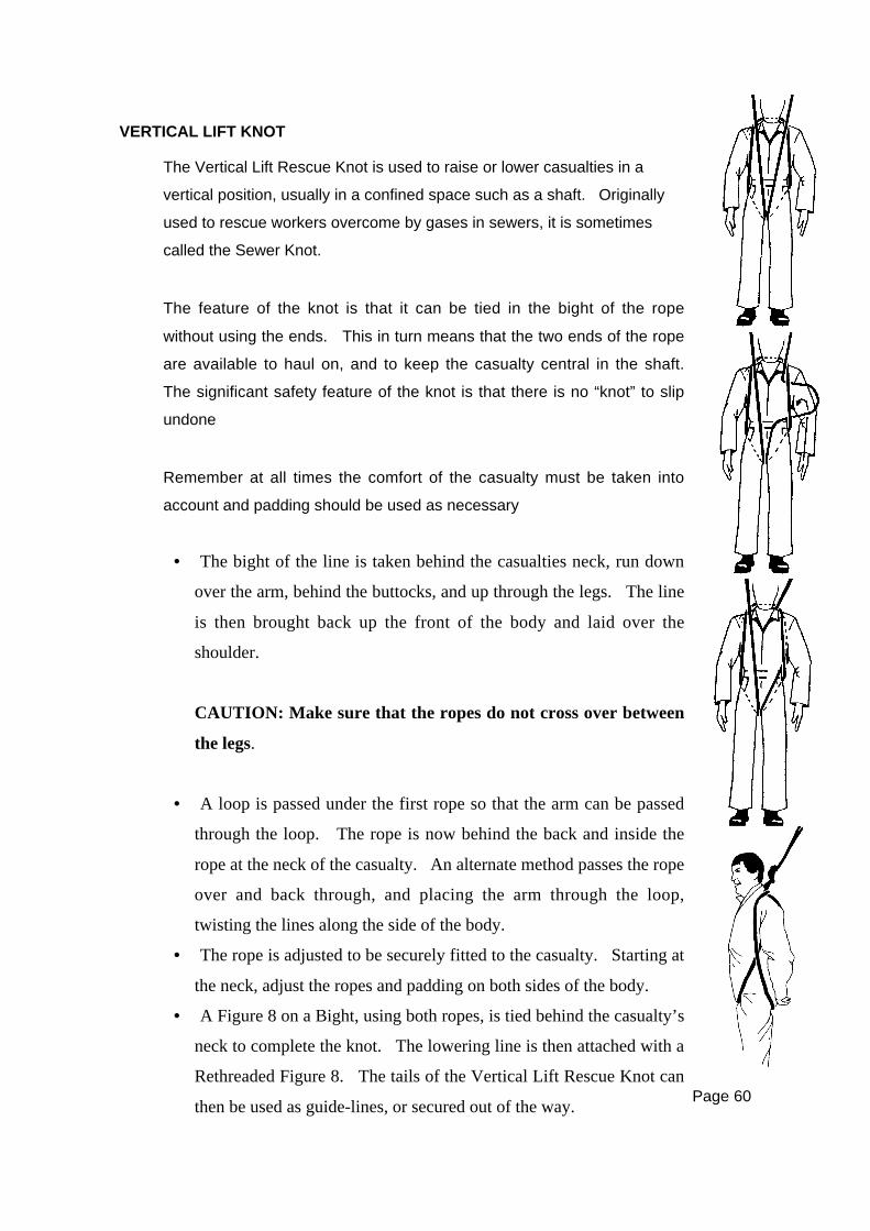
Page 60
VERTICAL LIFT KNOT
The Vertical Lift Rescue Knot is used to raise or lower casualties in a
vertical position, usually in a confined space such as a shaft. Originally
used to rescue workers overcome by gases in sewers, it is sometimes
called the Sewer Knot.
The feature of the knot is that it can be tied in the bight of the rope
without using the ends. This in turn means that the two ends of the rope
are available to haul on, and to keep the casualty central in the shaft.
The significant safety feature of the knot is that there is no “knot” to slip
undone
Remember at all times the comfort of the casualty must be taken into
account and padding should be used as necessary
• The bight of the line is taken behind the casualties neck, run down
over the arm, behind the buttocks, and up through the legs. The line
is then brought back up the front of the body and laid over the
shoulder.
CAUTION: Make sure that the ropes do not cross over between
the legs.
• A loop is passed under the first rope so that the arm can be passed
through the loop. The rope is now behind the back and inside the
rope at the neck of the casualty. An alternate method passes the rope
over and back through, and placing the arm through the loop,
twisting the lines along the side of the body.
• The rope is adjusted to be securely fitted to the casualty. Starting at
the neck, adjust the ropes and padding on both sides of the body.
• A Figure 8 on a Bight, using both ropes, is tied behind the casualty’s
neck to complete the knot. The lowering line is then attached with a
Rethreaded Figure 8. The tails of the Vertical Lift Rescue Knot can
then be used as guide-lines, or secured out of the way.
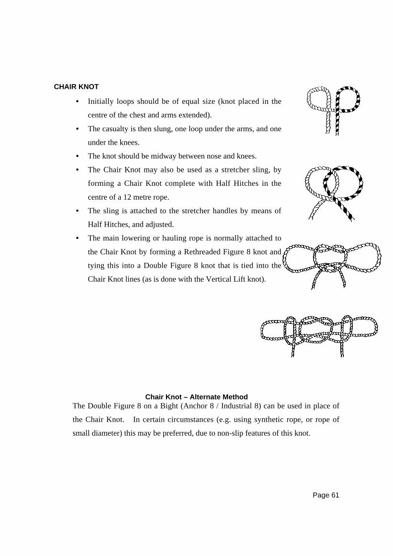
Page 61
CHAIR KNOT
Chair Knot – Alternate MethodThe Double Figure 8 on a Bight (Anchor 8 / Industrial 8) can be used in place of
the Chair Knot. In certain circumstances (e.g. using synthetic rope, or rope of
small diameter) this may be preferred, due to non-slip features of this knot.
• Initially loops should be of equal size (knot placed in the
centre of the chest and arms extended).
• The casualty is then slung, one loop under the arms, and one
under the knees.
• The knot should be midway between nose and knees.
• The Chair Knot may also be used as a stretcher sling, by
forming a Chair Knot complete with Half Hitches in the
centre of a 12 metre rope.
• The sling is attached to the stretcher handles by means of
Half Hitches, and adjusted.
• The main lowering or hauling rope is normally attached to
the Chair Knot by forming a Rethreaded Figure 8 knot and
tying this into a Double Figure 8 knot that is tied into the
Chair Knot lines (as is done with the Vertical Lift knot).

Page 62
LASHINGS
Lashing are mainly used to secure two or more poles firmly together. The form of
each type can best be understood by a careful study of the diagrams and appended
explanations.
Terminology
All poles or timbers in a vertical attitude or which will be raised vertically are
known as standards, while those used horizontally are referred to as ledgers.
Square LashingUsed to lash together two poles that touch and cross at right angles.• Start with a Clove Hitch
around the standard,
below the ledger ,
marrying the ends.
• Take the married ends up
and around both standard
and ledger as depicted by
the arrows.
• Repeat this circuit three
or four times, working
inwards on the standard
until the gap is filled,
keeping the rope as taut
as possible.
• Take three or four turns
around the whole lashing
between the poles, draw
taut, and finish with a
Clove Hitch on the
ledger.
• The square lashing
shown is shown from the
back.

Page 63
Diagonal LashingThis is used to lash together two poles that touch at an angle, especially when
their mode of use may cause them to spring apart.
Round LashingThis is used to lash together two poles that lie parallel to each other.
• Start with a Timber Hitch
a round bo th po les
horizontally, then take four
vertical turns and draw taut.
• Take four horizontal turns
and draw taut.
• Finally, put four turns over
the lashing, between the
poles, draw well taut, and
finish with a clove hitch.
• Insert spacing pieces about
50mm wide between the
poles.
• Start with a Clove Hitch
around one pole and
continue with 6 – 8 close
turns around both poles,
travelling upwards.
• Make two or three turns
around the lashing and
secure with a Clove Hitch on
the opposite pole to the
beginning of the lashing.
• Do not remove the spacing
pieces until the lashing is
completed.
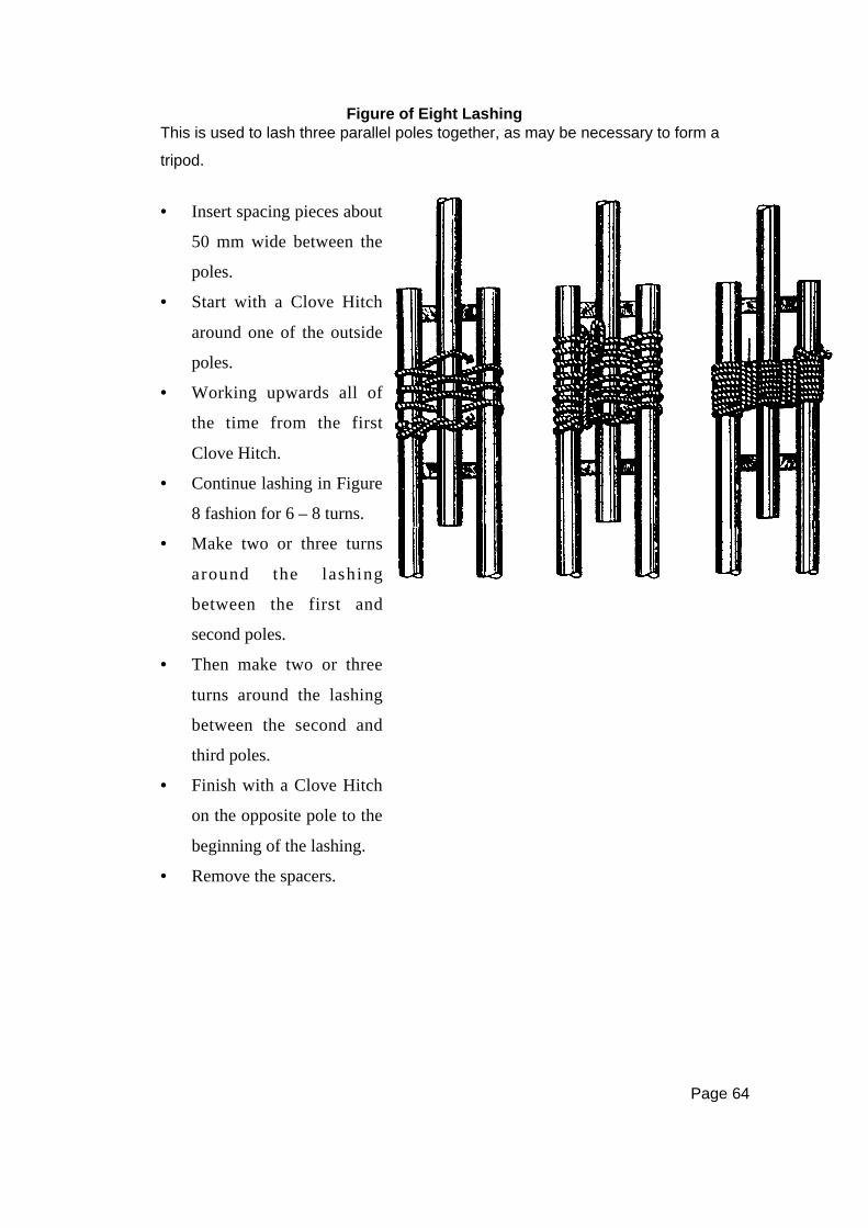
Page 64
Figure of Eight LashingThis is used to lash three parallel poles together, as may be necessary to form a
tripod.
• Insert spacing pieces about
50 mm wide between the
poles.
• Start with a Clove Hitch
around one of the outside
poles.
• Working upwards all of
the time from the first
Clove Hitch.
• Continue lashing in Figure
8 fashion for 6 – 8 turns.
• Make two or three turns
around the lashing
between the first and
second poles.
• Then make two or three
turns around the lashing
between the second and
third poles.
• Finish with a Clove Hitch
on the opposite pole to the
beginning of the lashing.
• Remove the spacers.
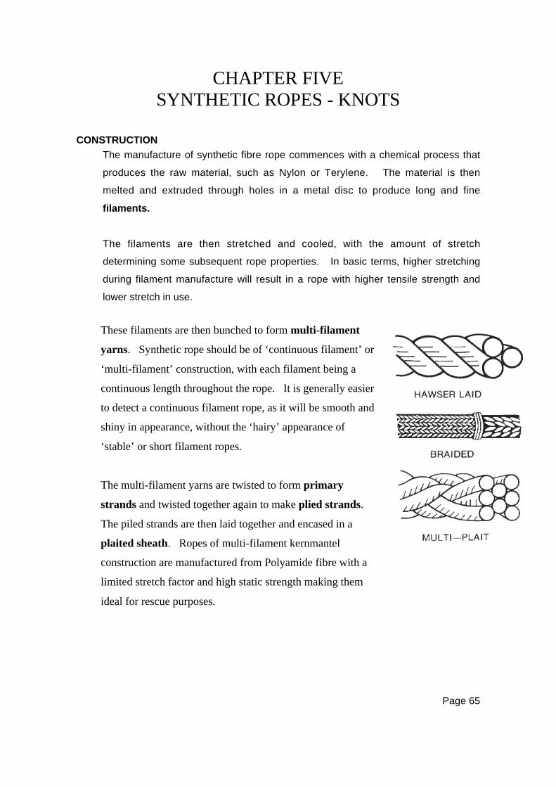
Page 65
CHAPTER FIVESYNTHETIC ROPES - KNOTS
CONSTRUCTION
The manufacture of synthetic fibre rope commences with a chemical process that
produces the raw material, such as Nylon or Terylene. The material is then
melted and extruded through holes in a metal disc to produce long and fine
filaments.
The filaments are then stretched and cooled, with the amount of stretch
determining some subsequent rope properties. In basic terms, higher stretching
during filament manufacture will result in a rope with higher tensile strength and
lower stretch in use.
These filaments are then bunched to form multi-filament
yarns. Synthetic rope should be of ‘continuous filament’ or
‘multi-filament’ construction, with each filament being a
continuous length throughout the rope. It is generally easier
to detect a continuous filament rope, as it will be smooth and
shiny in appearance, without the ‘hairy’ appearance of
‘stable’ or short filament ropes.
The multi-filament yarns are twisted to form primary
strands and twisted together again to make plied strands.
The piled strands are then laid together and encased in a
plaited sheath. Ropes of multi-filament kernmantel
construction are manufactured from Polyamide fibre with a
limited stretch factor and high static strength making them
ideal for rescue purposes.
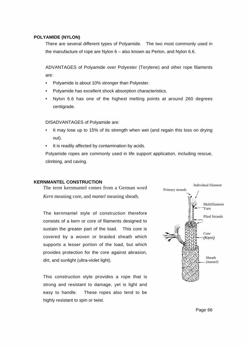
Page 66
POLYAMIDE (NYLON)
There are several different types of Polyamide. The two most commonly used in
the manufacture of rope are Nylon 6 – also known as Perlon, and Nylon 6.6.
ADVANTAGES of Polyamide over Polyester (Terylene) and other rope filaments
are:
• Polyamide is about 10% stronger than Polyester.
• Polyamide has excellent shock absorption characteristics.
• Nylon 6.6 has one of the highest melting points at around 260 degrees
centigrade.
DISADVANTAGES of Polyamide are:
• It may lose up to 15% of its strength when wet (and regain this loss on drying
out).
• It is readily affected by contamination by acids.
Polyamide ropes are commonly used in life support application, including rescue,
climbing, and caving.
KERNMANTEL CONSTRUCTION
MultifilamentYarn
Individual filamentPrimary strandsThe term kernmantel comes from a German word
Kern meaning core, and mantel meaning sheath.
The kernmantel style of construction therefore
consists of a kern or core of filaments designed to
sustain the greater part of the load. This core is
covered by a woven or braided sheath which
supports a lesser portion of the load, but which
provides protection for the core against abrasion,
dirt, and sunlight (ultra-violet light).
This construction style provides a rope that is
strong and resistant to damage, yet is light and
easy to handle. These ropes also tend to be
highly resistant to spin or twist.
Plied Strands
Core(Kern)
Sheath(mantel)
Page 67
STATIC KERNMANTEL ROPES
Elongation
A static rope is one designed with low elongation characteristics. These ropes
normally elongate around 3% under one person’s body weight, and not more than
10 to 20% at ultimate breaking point.
Elasticity
The stretch of a static rope is normally attributable to the elasticity of the rope
filaments. Static ropes have poor shock absorbing qualities, and any shock
loading subjects the rescuer’s body, the equipment in the system, and the anchor
system, to high impact forces.
Strength Vs HandlingStatic ropes tend to have thicker sheaths for greater core protection. The
increased sheath contributes more to the overall rope strength, but results in a
stiffer rope with poorer rope handling characteristics.
ADVANTAGES of static ropes are:
• Low stretch
• Resistance to abrasion
• High tensile strength
DISADVANTAGES of static ropes are:
• Poor capacity for shock absorption
• Stiffer handling and knotting.
WARNING NOTE:
All ropes used in a rescue system must have identical characteristics
to avoid unequal stretch and load reactions.
Page 68
CHARACTERISTICS OF A SYNTHETIC FIBRE STATIC RESCUE ROPE
The criteria for synthetic fibre ropes are laid down in Australian Standard
AS4142.3— 1993, (Fibre ropes—Part 3 Man-made fibre rope for static life rescue
lines):
• Minimum diameter 11mm
• Static kernmantel construction
• Minimum rated strength 3000kg
• 100% Polyamide (Nylon)
•••• Spin resistant
• Abrasion resistant
• Good handling and knotting properties
• Maximum 3% elongation at 80kg load
• Maximum 10% elongation at 375kg load
• Maximum 20% elongation at 3000kg load
• Contrasting core and sheath colours
• Coded with an identification tape in the core.
CARE AND MAINTENANCE
The following points should be observed:
• Avoid cutting a rope unless it is essential to do so. If it is necessary, ensure
the cut end is heat sealed as soon as possible to prevent fraying. (As a
temporary measure, tie a Figure 8 knot near the end of the rope or secure it
with adhesive tape.)
• Do not leave knots in a rope as they considerably reduce its strength by
seriously damaging the fibres.
• Always use proven knots and fastenings for ropes. Sharp bends or knots can
overload elements of the rope. Swayed eyes at rope ends should be avoided.
• Use the correct size sheave in pulleys. Any attempt to force a thick rope
through a smaller pulley will cause damage.
• Avoid shock-loading, sudden jerks or violent stress on the rope.
• Avoid stepping or walking on the rope as this will force damaging grit and dirt
into the fibres.
• Avoid passing a rope over a sharp edge or rough surface. If it is necessary to
do this, protect the rope with sacking or other material.
Page 69
• Ropes that have been hauled through mud, sand, or grit, should always be
cleaned after the work has been completed. This is best managed by washing
the rope in fresh, running water and following any manufacturer’s
recommendations.
• Do not dry ropes in front of a fire or other heat source. Spread the rope on a
ladder, laid horizontally off the ground in a cool, shady area to enable the air to
circulate freely around the rope.
• Store ropes under cover, off the floor, preferably in racks, in a place free from
extremes of temperature and out of contact with any contaminating materials.
• Damaged or defective ropes must be appropriately labelled and removed from
service immediately. Details must then be entered on the rope history record
card.
• Ropes should not be exposed to direct sunlight for prolonged periods as the
fibres will degrade due to ultra-violet radiation. If a rope has to be stored in an
exposed location, cover it with a tarpaulin or some other form of protection.
• Ensure no contact is made with contaminants such as grease, oil, petrol,
hydraulic fluid, acids, alkalis, and chemicals.
WASHING ROPES
Ropes should be washed when dirty to reduce the effect of grit abrasion on both
the rope and the equipment. The rope can be chained to prevent tangling.
Polyamide ropes can be washed in a washing machine, but the machine must be
set on the cold or warm setting (never on hot) and no washing agents or fabric
softeners should be used.
Where help is needed to clean a particularly dirty rope, refer to the rope
manufacturer’s specifications.
The washed rope can be pulled under a very slight tension through an in-line
descender to remove excess water, and the rope dried in a cool shady area with
good ventilation.
Page 70
INSPECTION
WARNING NOTE:
Load testing of ropes is not recommended as a safe practice.
All ropes should be inspected before, during, and after use. The inspection
should be carried out by visually examining the rope and by thoroughly feeling
the rope.
Visual examination should check for the following signs:• Discolouration Of The Filaments: Any changes in the original colour of the rope
filaments could indicate contamination by chemicals.
• Melting: Any smooth areas could indicate the rope has been damaged by heat
fusion.
• White Filaments: Where the sheath has been damaged, the white core filaments
may protrude.
• Size Uniformity: The rope may be damaged by mechanical impacts or over
stressing. This may be evidenced by a change in the obvious shape and
diameter of the rope.
• Abrasion: Excessive signs of abrasion may indicate the breaking of a sheath
bundle and localised weakness.
• Stiffness: Any inconsistency in the texture of a rope and its stiffness. A bight of
rope should have uniform radius around the bend, and inconsistencies may be
soft spots that indicate core damage.
Thoroughly feeling the rope should check for these additional signs:
− STIFFENED FILAMENTS: This indicates possible overloading or
contamination.
− CHANGES IN DIAMETER: Depressed irregularities in the rope diameter
(soft spots) may indicate core damage, while increases in the apparent
Page 71
diameter may be due to severe twisting of the core, or the protrusion of
core filaments through the sheath.
• Contamination: Presence of dirt or other materials.
RETIRING A ROPE
It is currently impossible to properly test a rope without destroying it, and the
decision to retire a rope from service must therefore be based on careful
inspection by a confident Rescue Instructor. The following guidelines will assist in
deciding when to retire a rescue rope:
• Abrasion. As a general rule when more than half of the sheath yarns are broken,or the abrasion ‘fuzz’ stands out from the sheath more than 25% of the ropediameter.
• Loading. Where the rope is known to have sustained a shock loading or to havebeen overloaded, it should be retired.
• Contamination. Unless the material with which the rope has come into contactwith is harmless, it should be considered as contaminated.
• Texture. A lack of uniformity of texture such as soft or hard spots.• Diameter. Variations in the observable diameter of the rope such as soft or hard
spots.• Sheath Protection. Where the white core filaments are visible through a hole in
the sheath, or where the core protrudes through the sheath as a white filament‘puff’.
Whilst some services may have a policy on the life or limit of use of a rope, the
bottom line with regard to rope retirement must be:
IF IN DOUBT, THROW IT OUT.
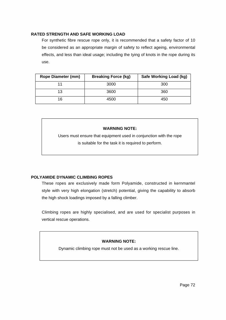
Page 72
RATED STRENGTH AND SAFE WORKING LOAD
For synthetic fibre rescue rope only, it is recommended that a safety factor of 10
be considered as an appropriate margin of safety to reflect ageing, environmental
effects, and less than ideal usage; including the tying of knots in the rope during its
use.
Rope Diameter (mm) Breaking Force (kg) Safe Working Load (kg)
11 3000 300
13 3600 360
16 4500 450
WARNING NOTE:
Users must ensure that equipment used in conjunction with the rope
is suitable for the task it is required to perform.
POLYAMIDE DYNAMIC CLIMBING ROPES
These ropes are exclusively made form Polyamide, constructed in kernmantel
style with very high elongation (stretch) potential, giving the capability to absorb
the high shock loadings imposed by a falling climber.
Climbing ropes are highly specialised, and are used for specialist purposes in
vertical rescue operations.
WARNING NOTE:
Dynamic climbing rope must not be used as a working rescue line.
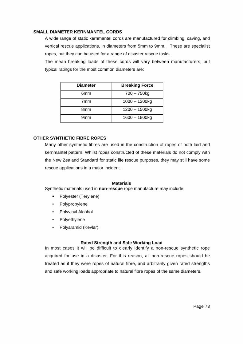
Page 73
SMALL DIAMETER KERNMANTEL CORDS
A wide range of static kernmantel cords are manufactured for climbing, caving, and
vertical rescue applications, in diameters from 5mm to 9mm. These are specialist
ropes, but they can be used for a range of disaster rescue tasks.
The mean breaking loads of these cords will vary between manufacturers, but
typical ratings for the most common diameters are:
Diameter Breaking Force
6mm 700 – 750kg
7mm 1000 – 1200kg
8mm 1200 – 1500kg
9mm 1600 – 1800kg
OTHER SYNTHETIC FIBRE ROPES
Many other synthetic fibres are used in the construction of ropes of both laid and
kernmantel pattern. Whilst ropes constructed of these materials do not comply with
the New Zealand Standard for static life rescue purposes, they may still have some
rescue applications in a major incident.
MaterialsSynthetic materials used in non-rescue rope manufacture may include:
•••• Polyester (Terylene)
• Polypropylene
• Polyvinyl Alcohol
• Polyethylene
• Polyaramid (Kevlar).
Rated Strength and Safe Working LoadIn most cases it will be difficult to clearly identify a non-rescue synthetic rope
acquired for use in a disaster. For this reason, all non-rescue ropes should be
treated as if they were ropes of natural fibre, and arbitrarily given rated strengths
and safe working loads appropriate to natural fibre ropes of the same diameters.
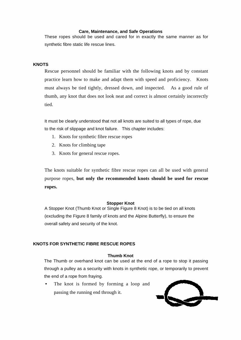
Page 74
Care, Maintenance, and Safe OperationsThese ropes should be used and cared for in exactly the same manner as for
synthetic fibre static life rescue lines.
KNOTS
Rescue personnel should be familiar with the following knots and by constant
practice learn how to make and adapt them with speed and proficiency. Knots
must always be tied tightly, dressed down, and inspected. As a good rule of
thumb, any knot that does not look neat and correct is almost certainly incorrectly
tied.
It must be clearly understood that not all knots are suited to all types of rope, due
to the risk of slippage and knot failure. This chapter includes:
1. Knots for synthetic fibre rescue ropes
2. Knots for climbing tape
3. Knots for general rescue ropes.
The knots suitable for synthetic fibre rescue ropes can all be used with general
purpose ropes, but only the recommended knots should be used for rescue
ropes.
Stopper KnotA Stopper Knot (Thumb Knot or Single Figure 8 Knot) is to be tied on all knots
(excluding the Figure 8 family of knots and the Alpine Butterfly), to ensure the
overall safety and security of the knot.
KNOTS FOR SYNTHETIC FIBRE RESCUE ROPES
Thumb KnotThe Thumb or overhand knot can be used at the end of a rope to stop it passing
through a pulley as a security with knots in synthetic rope, or temporarily to prevent
the end of a rope from fraying.
• The knot is formed by forming a loop and
passing the running end through it.
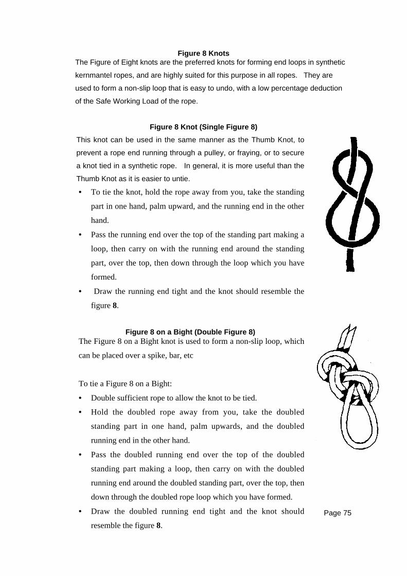
Page 75
Figure 8 KnotsThe Figure of Eight knots are the preferred knots for forming end loops in synthetic
kernmantel ropes, and are highly suited for this purpose in all ropes. They are
used to form a non-slip loop that is easy to undo, with a low percentage deduction
of the Safe Working Load of the rope.
Figure 8 Knot (Single Figure 8)
This knot can be used in the same manner as the Thumb Knot, to
prevent a rope end running through a pulley, or fraying, or to secure
a knot tied in a synthetic rope. In general, it is more useful than the
Thumb Knot as it is easier to untie.
• To tie the knot, hold the rope away from you, take the standing
part in one hand, palm upward, and the running end in the other
hand.
• Pass the running end over the top of the standing part making a
loop, then carry on with the running end around the standing
part, over the top, then down through the loop which you have
formed.
• Draw the running end tight and the knot should resemble the
figure 8.
Figure 8 on a Bight (Double Figure 8)The Figure 8 on a Bight knot is used to form a non-slip loop, which
can be placed over a spike, bar, etc
To tie a Figure 8 on a Bight:
• Double sufficient rope to allow the knot to be tied.
• Hold the doubled rope away from you, take the doubled
standing part in one hand, palm upwards, and the doubled
running end in the other hand.
• Pass the doubled running end over the top of the doubled
standing part making a loop, then carry on with the doubled
running end around the doubled standing part, over the top, then
down through the doubled rope loop which you have formed.
• Draw the doubled running end tight and the knot should
resemble the figure 8.
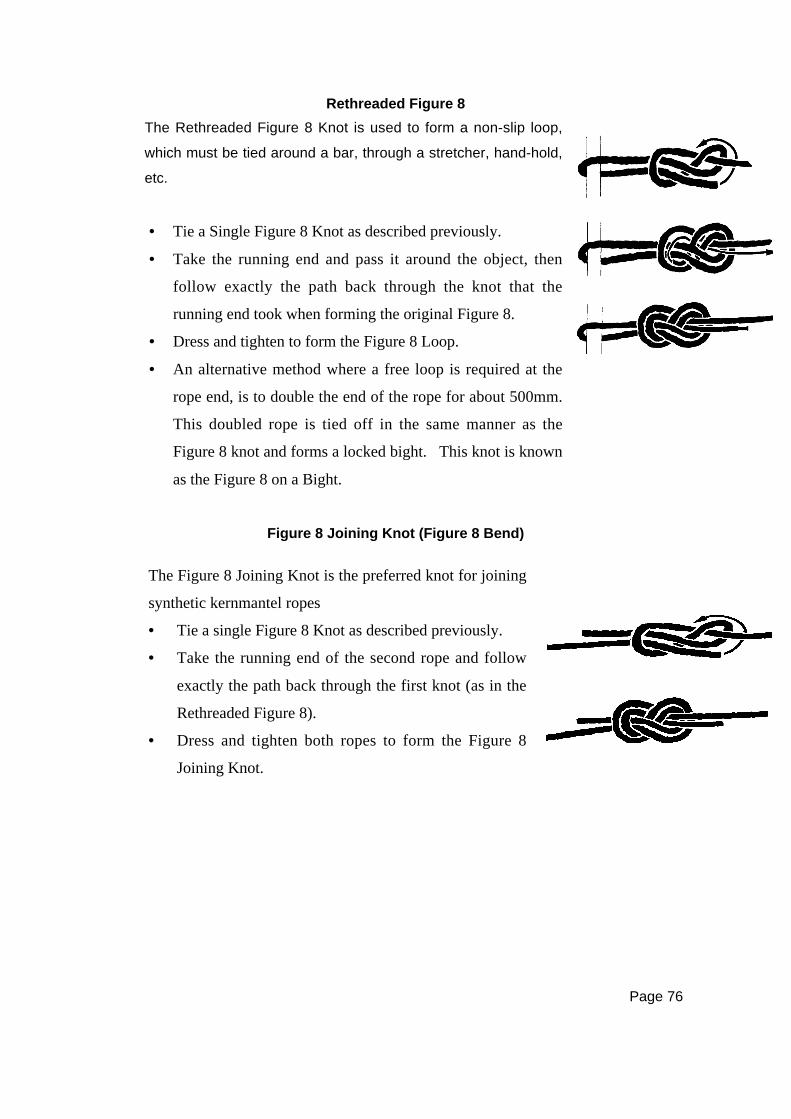
Page 76
Rethreaded Figure 8
Figure 8 Joining Knot (Figure 8 Bend)
The Rethreaded Figure 8 Knot is used to form a non-slip loop,
which must be tied around a bar, through a stretcher, hand-hold,
etc.
• Tie a Single Figure 8 Knot as described previously.
• Take the running end and pass it around the object, then
follow exactly the path back through the knot that the
running end took when forming the original Figure 8.
• Dress and tighten to form the Figure 8 Loop.
• An alternative method where a free loop is required at the
rope end, is to double the end of the rope for about 500mm.
This doubled rope is tied off in the same manner as the
Figure 8 knot and forms a locked bight. This knot is known
as the Figure 8 on a Bight.
The Figure 8 Joining Knot is the preferred knot for joining
synthetic kernmantel ropes
• Tie a single Figure 8 Knot as described previously.
• Take the running end of the second rope and follow
exactly the path back through the first knot (as in the
Rethreaded Figure 8).
• Dress and tighten both ropes to form the Figure 8
Joining Knot.

Page 77
Double Figure 8 on a Bight (Anchor 8 or Industrial 8)
Round Turn and Two Half Hitches
This is an exceptionally strong knot to form loops at the end
of a rope. It allows you to independently adjust the loops,
so that each loop can be used as an anchor point.
• To tie, start with a basic Fig 8 on the Bight, except do
not pass the Bight through the final loop.
• Form a new Bight in that end, and place this through the
final loop.
• Place the original Bight (single rope loop) over the
double and pull it down to the base of the knot.
• To check that it has been tied correctly, there should be
3 loops of rope around the base of the knot and 2
separate bights of rope coming out the end of the knot.
This knot is used for securing the running end of a rope to a spar
or ring, and is suited to both synthetic and natural fibre rope.
• It is formed by a round turn on the spar or ring, with two Half
Hitches on the standing part of the rope.
• It has the great advantage of allowing a load to be adjusted
using the round turn, then finally secured by forming the two
Half Hitches on the standing part.
• Extra round turns raise the breaking strain of this knot.
• Finish with a stopper knot.

Page 78
Alpine Butterfly
This is a very strong and useful knot for forming a locked loop at
any point of synthetic or natural fibre rope.
There is some confusion in literature as to what constitutes an
Alpine Butterfly.
The knots shown are correct in that they form a locked loop which
can sustain a three-way loading.
To tie the knot,
• Pass the running end around the palm two times, laying the
ropes beside each other, with a gap in between.
• Pass the rope around a third time, laying the rope between the
other two.
• Pick up the outside rope, pull out slightly to form a loop, and
pass the loop on top of the other two, and then down to pass
between the palm and the ropes.
• Pull the loop out from the palm.
• Slide the knot off the hand.
• Pull the ends and loop to dress and secure the knot.
An optional method of tying the Alpine Butterfly is:
• Pick up a Bight of rope.
• Twist the Bight twice in the same direction, holding each of
the crossovers.
• Pass the free end of the loop through the opening formed
between the two cross-overs.
• Cradle the knot in one hand.
• Pull on each side of the loop to dress and tighten the knot.
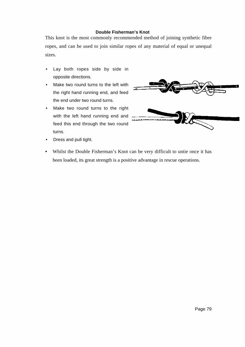
Page 79
Double Fisherman’s KnotThis knot is the most commonly recommended method of joining synthetic fibre
ropes, and can be used to join similar ropes of any material of equal or unequal
sizes.
• Whilst the Double Fisherman’s Knot can be very difficult to untie once it has
been loaded, its great strength is a positive advantage in rescue operations.
• Lay both ropes side by side in
opposite directions.
• Make two round turns to the left with
the right hand running end, and feed
the end under two round turns.
• Make two round turns to the right
with the left hand running end and
feed this end through the two round
turns.
• Dress and pull tight.

Page 80
Prusik KnotThe Prusik Knot is a method in which a cord sling can be attached to a rope to
provide an attachment loop or hand loop.
• It is now ready to use, in conjunction with a Karabiner, or similar device.
• To move the knot along the rope, remove the pressure, and slide the knot along
by pushing at the turns around the rope.
The position of the loop can be easily adjusted on the main rope.
The cord sling must be at least 3mm smaller in diameter than the
main rope for the knot to work, and the Prusik Knot must never be
shock loaded.
To tie the Prusik Knot,
• Form the loop by joining the ends of the cord with a Double
Fisherman’s Knot (as shown previously).
• Place the looped cord over the rope and pass one loop (the first
loop) inside the other part of the loop (the second loop).
• Pass the first loop through the second loop two more times (so
that there are three passes of the cord on each side).
• Pull the first loop evenly to ‘lock’ the turns around the rope.
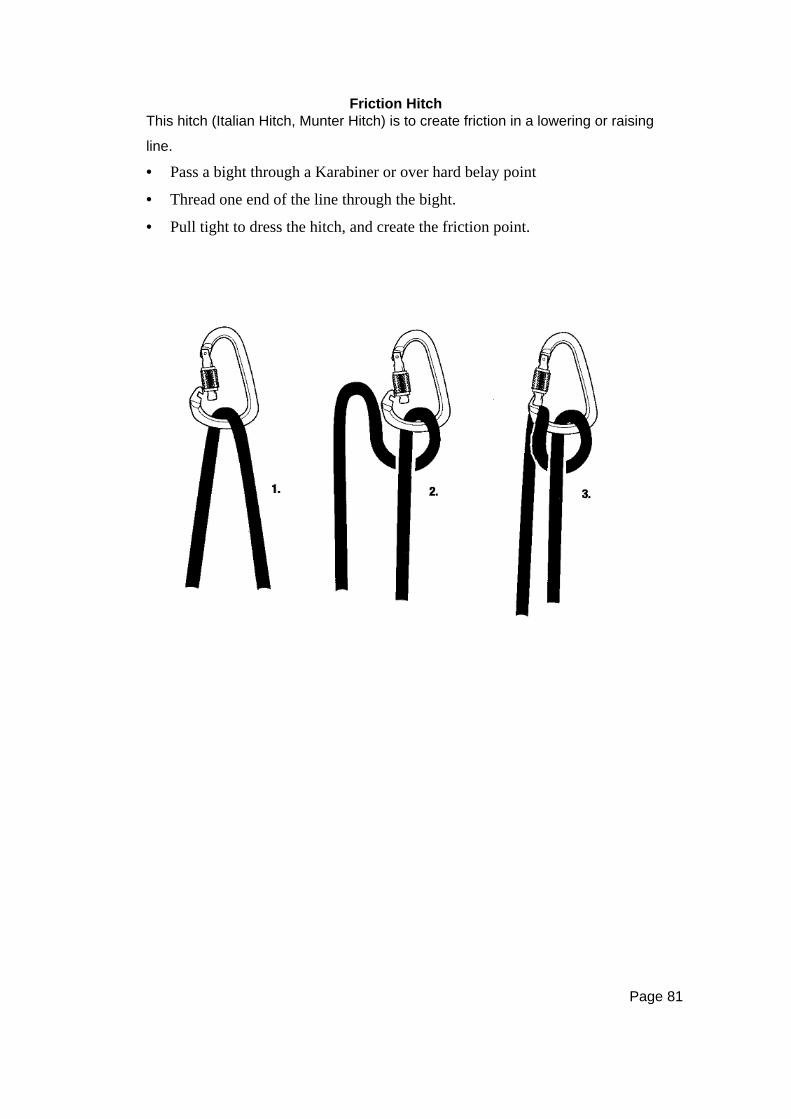
Page 81
Friction HitchThis hitch (Italian Hitch, Munter Hitch) is to create friction in a lowering or raising
line.
• Pass a bight through a Karabiner or over hard belay point
• Thread one end of the line through the bight.
• Pull tight to dress the hitch, and create the friction point.

Page 83
CHAPTER SIXNATURAL FIBRE ROPES - KNOTS
INTRODUCTION
WARNING NOTE:
Natural fibre ropes are only to be used for rescue as a last resort.
Ropes may be made from a variety of natural materials, the most common of
which are Manila, Sisal, Hemp, and Cotton. Manila and Sisal are hard fibres,
while Hemp and Cotton are soft fibres. Manila and Sisal were the two materials
used in the manufacture of natural fibre rope for rescue operations prior to the
adoption of the synthetic fibre rope standard.
The comparison of Manila and Sisal fibres follows:
•••• Sisal has a harder fibre and therefore makes a stiffer rope.
• New Sisal is white in colour, while Manila is light brown.
• Both fibres are similar in weight.
• Ropes made of both fibres have similar working loads.
• Sisal absorbs moisture more readily than Manila and deteriorates more rapidly.
CONSTRUCTION
Most natural fibre rope is constructed by taking a number of threads or fibres and
twisting them into yarns. The yarns are then twisted to make strands and the
strands (generally three in number) are laid together to make the finished rope.
The number of fibres in the yarns and the number of yarns determine the size of
the rope. This type of rope can be left-hand lay or more commonly right-hand lay,
which is termed ‘Plain’ or ‘Hawser Laid’ rope.

Page 84
CARE AND MAINTENANCE
•••• Avoid cutting a rope unless it is essential to do so. If it is necessary, ensure
the cut end is whipped (if laid rope) as soon as possible to prevent fraying. As
a temporary measure, a Figure 8 Knot can be tied near the end of the rope, or
adhesive tape applied.
• Avoid permanent knots in a rope as they considerably reduce its strength by
seriously damaging the fibres.
• Avoid, as far as possible, dragging the ropes over rough or sharp surfaces.
• Always use proven knots and fastenings for ropes. Sharp bends or knots can
cause some parts of the rope to become overloaded.
• Use correct pulleys, as an attempt to force thick rope through a narrow pulley
will cause damage to both elements. Additionally, use cordage blocks and
Steel Wire Rope SWR blocks for steel wire rope.
• Avoid shock loading or overloading of ropes or slings.
• Do not step on rope as this will introduce damaging grit and dirt into the fibres.
• Avoid passing a rope over a sharp edge. If this is unavoidable, pad the edge
to prevent damage to the rope.
• Ropes that have been worked through mud, sand, or grit should always be
cleaned after the work has been completed. This is best managed by washing
the rope with clean running water. No form of solvent or cleaning agent should
be used.
• Do not dry ropes in front of a fire or other heat source. Spread the rope on a
ladder, laid horizontally off the ground to enable the air to circulate freely
around the rope.
• Store all ropes under cover, off the floor, and preferably on storage racks. The
store should be free of extremes of temperature and from any source of
moisture which will particularly affect natural fibre rope.
• Keep all ropes out of contact with any contaminating material such as acids,
alkalis, solvents, and the like.
• Try to keep storage area free of rodents, and other vermin.
• If a rope has to be temporarily stored in an exposed location, it should be
covered with a tarpaulin or some other form of protection.
• Report damaged or defective items as soon as possible, enter details in the
record system and ensure the defect is remedied.
Page 85
• Regularly inspect the quality of whipping in laid rope. Repair these as
required.
• Ensure than natural fibre ropes are not exposed to sunlight for prolonged
periods of time, as they will degrade due to the ultra-violet radiation.
INSPECTION OF LAID ROPE
It is essential to have sufficient space to handle the full length of the rope in
systematic fashion, and to have good light. The entire length of the rope should
be inspected in sections of approximately 300mm at a time, by gently twisting
against the lay to expose the inner surfaces of the strands for inspection. Return
the strands to their original positions afterwards. The outer layer of the strands
must also be inspected.
Check the exterior of the rope for the following:
•••• Broken fibres – abrasions
• Cuts
• Soft spots – a sure sign of wear
•••• Decay or burns – heat or chemical
• Any other deformation or irregularity.
Check the interior of the rope for the following:
•••• Broken fibres
• Powdering – indicating internal damage or overloading
• Dry rot or mildew
•••• Change in colour
• Any odour of mildew, rot, etc.
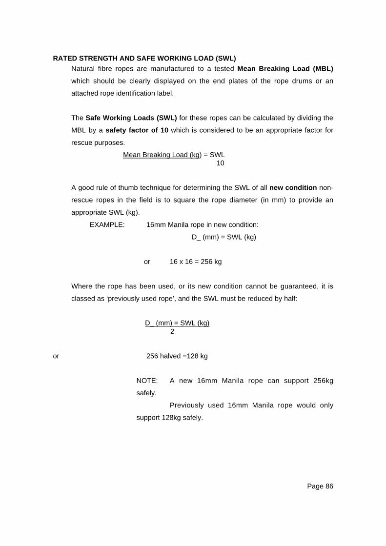
Page 86
RATED STRENGTH AND SAFE WORKING LOAD (SWL)
Natural fibre ropes are manufactured to a tested Mean Breaking Load (MBL)
which should be clearly displayed on the end plates of the rope drums or an
attached rope identification label.
The Safe Working Loads (SWL) for these ropes can be calculated by dividing the
MBL by a safety factor of 10 which is considered to be an appropriate factor for
rescue purposes.
Mean Breaking Load (kg) = SWL10
A good rule of thumb technique for determining the SWL of all new condition non-
rescue ropes in the field is to square the rope diameter (in mm) to provide an
appropriate SWL (kg).
EXAMPLE: 16mm Manila rope in new condition:
D_ (mm) = SWL (kg)
or 16 x 16 = 256 kg
Where the rope has been used, or its new condition cannot be guaranteed, it is
classed as ‘previously used rope’, and the SWL must be reduced by half:
D_ (mm) = SWL (kg) 2
or 256 halved =128 kg
NOTE: A new 16mm Manila rope can support 256kg
safely.
Previously used 16mm Manila rope would only
support 128kg safely.
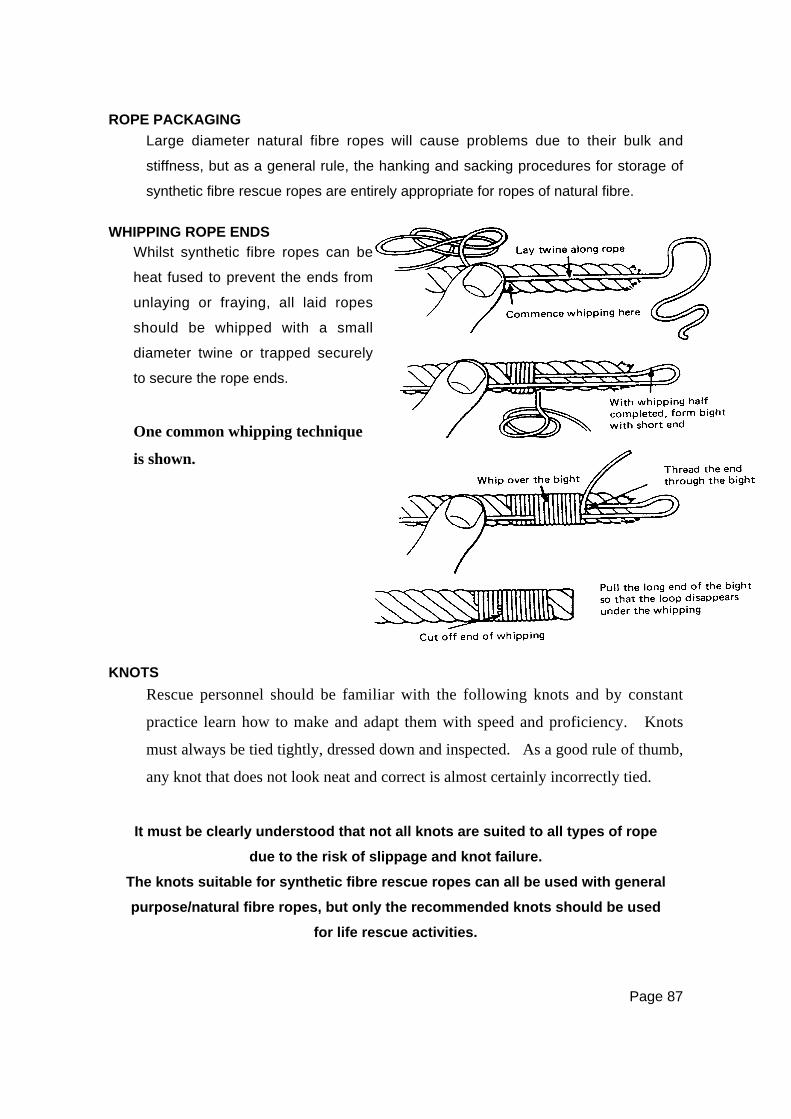
Page 87
ROPE PACKAGING
Large diameter natural fibre ropes will cause problems due to their bulk and
stiffness, but as a general rule, the hanking and sacking procedures for storage of
synthetic fibre rescue ropes are entirely appropriate for ropes of natural fibre.
WHIPPING ROPE ENDS
KNOTS
Rescue personnel should be familiar with the following knots and by constant
practice learn how to make and adapt them with speed and proficiency. Knots
must always be tied tightly, dressed down and inspected. As a good rule of thumb,
any knot that does not look neat and correct is almost certainly incorrectly tied.
It must be clearly understood that not all knots are suited to all types of rope
due to the risk of slippage and knot failure.
The knots suitable for synthetic fibre rescue ropes can all be used with general
purpose/natural fibre ropes, but only the recommended knots should be used
for life rescue activities.
Whilst synthetic fibre ropes can be
heat fused to prevent the ends from
unlaying or fraying, all laid ropes
should be whipped with a small
diameter twine or trapped securely
to secure the rope ends.
One common whipping technique
is shown.

Page 88
Stopper KnotA Stopper Knot (Thumb Knot or Single Figure 8 Knot) is to be tied on all knots, to
ensure the overall safety and security of the knot.
Thumb Knot
Figure 8 Knot (Single Figure 8)This knot can be used in the same manner as the Thumb Knot, to prevent a rope
end running through a pulley, or fraying, or to secure a knot tied in a synthetic
rope. In general, it is more useful than the Thumb Knot as it is easier to untie.
General Purpose KnotsHalf Hitch
The Thumb or overhand knot can be used at the end
of a rope to stop it passing through a pulley as a
security with knots in synthetic rope, or temporarily to
prevent the end of a rope from fraying.
• The knot is formed by forming a loop and passing
the running end through it.
To tie the knot:
• Hold the rope away from you, take the standing part in one
hand, palm upward, and the running end in the other hand.
• Pass the running end over the top of the standing part
making a loop, then carry on with the running end around
the standing part, over the top, then down through the loop
that you have formed.
• Draw the running end tight and the knot should resemble the
figure 8.
This is formed by passing the running end of a rope around a
spar (or around another rope) and under the standing part so
that when pulled, one part of the rope binds on the other.
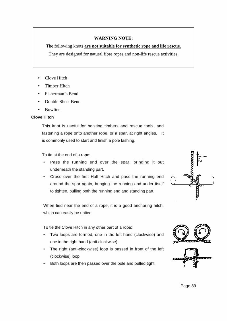
Page 89
WARNING NOTE:
The following knots are not suitable for synthetic rope and life rescue.
They are designed for natural fibre ropes and non-life rescue activities.
• Clove Hitch
• Timber Hitch
• Fisherman’s Bend
• Double Sheet Bend
• Bowline
Clove Hitch
This knot is useful for hoisting timbers and rescue tools, and
fastening a rope onto another rope, or a spar, at right angles. It
is commonly used to start and finish a pole lashing.
To tie at the end of a rope:
• Pass the running end over the spar, bringing it out
underneath the standing part.
• Cross over the first Half Hitch and pass the running end
around the spar again, bringing the running end under itself
to tighten, pulling both the running end and standing part.
When tied near the end of a rope, it is a good anchoring hitch,
which can easily be untied
To tie the Clove Hitch in any other part of a rope:
• Two loops are formed, one in the left hand (clockwise) and
one in the right hand (anti-clockwise).
• The right (anti-clockwise) loop is passed in front of the left
(clockwise) loop.
• Both loops are then passed over the pole and pulled tight
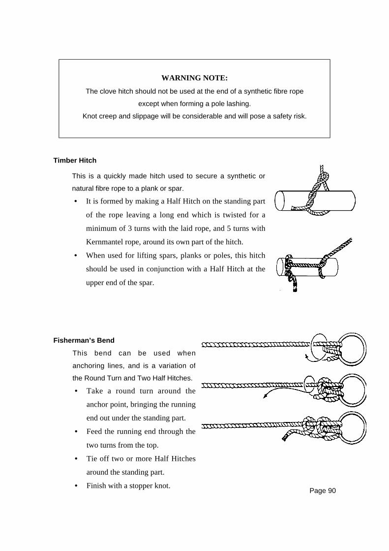
Page 90
WARNING NOTE:
The clove hitch should not be used at the end of a synthetic fibre rope
except when forming a pole lashing.
Knot creep and slippage will be considerable and will pose a safety risk.
Timber Hitch
Fisherman’s Bend
This is a quickly made hitch used to secure a synthetic or
natural fibre rope to a plank or spar.
• It is formed by making a Half Hitch on the standing part
of the rope leaving a long end which is twisted for a
minimum of 3 turns with the laid rope, and 5 turns with
Kernmantel rope, around its own part of the hitch.
• When used for lifting spars, planks or poles, this hitch
should be used in conjunction with a Half Hitch at the
upper end of the spar.
This bend can be used when
anchoring lines, and is a variation of
the Round Turn and Two Half Hitches.
• Take a round turn around the
anchor point, bringing the running
end out under the standing part.
• Feed the running end through the
two turns from the top.
• Tie off two or more Half Hitches
around the standing part.
• Finish with a stopper knot.

Page 91
Double Sheet Bend
• Pass the running end around both thicknesses of the thicker rope and pass under
its own standing part a second time.
• Ideally the running ends of both ropes are on the same side of the finished knot.
BowlineThe Bowline is a knot that is only safely suited to laid ropes.
A bowline is not safe for use with synthetic fibre ropes of
Kernmantel construction, due to the high risk of knot creep.
The Figure 8 Loop, or Figure 8 on the Bight, should be used for safety.
This bend is used for joining natural fibre laid ropes
regardless of their diameter.
• It is made by forming a bight in the thicker of
the two ropes and holding this in the left hand.
• Pass the running end of the smaller rope up
through the bight and around both thicknesses of
the thicker rope and pass under its own standing
part.
• Hold the rope in the left hand and form a small loop over
the top of the standing part.
• Hold the loop in place with the thumb of the left hand.
• Feed the running end through the back of the loop, round
the standing part and tuck the end back through the loop.
• Dress and pull tight.
• Adjust to the correct tension.
• Finish with a stopper knot.
Page 92
KNOT SAFETY
The following points relating to knot safety should be observed in all activities:
• Knots must be selected which are appropriate to the task and to the rope in
use. This is of particular importance with synthetic fibre Kernmantel ropes.
• Any knots tied, at or near, the end of a synthetic fibre rope can be protected
with a Thumb Knot tied on the inactive side of the knot to prevent slippage.
• Knots must be tied with a minimum tail of 100mm protruding from the knot.
• All knots must be monitored and checked throughout any operation.
• Knots must not be left permanently in a rope as they will deform the rope fibres
and weaken the rope.
• Due to the risk of knot creep and failure when forming knots in synthetic fibre
ropes, all tasks for which the Bowline may traditionally have been used, should
now be accomplished with one of the Figure 8 family of knots.
KNOT STRENGTH
It should be noted that the safety factor of 10, which is normally applied to ropes in
use, takes into account the reduction of strength caused by tying knots.
Page 93
CHAPTER SEVENANCHORS AND HOLDFASTS
INTRODUCTION
Anchors and holdfasts are used in rescue for the purpose of securing a line, rope,
or wire that will be under load. They fall into three main classes:
1. Natural – Trees and boulders
2. Constructed – Those that have to be set up (eg. by use of pickets and
lashings, anchor devices, buried baulks, or timber)
3. Improvised – Those found on the site, (eg. Reinforced concrete or metal
standards, metal framework of buildings, baulks of timber across door
openings, etc).
NATURAL ANCHORS
The most readily identifiable anchor points are trees, large rocks, and spikes of
rock. These must be carefully selected, with regard to load and direction of load.
These points should not be too close to risk areas, and must be tested by a
hauling crew before use.
CONSTRUCTED ANCHORS
Picket HoldfastsPickets are suitable as anchors, used as single pickets.
It is recommended they be placed into a holdfast
system. These can be arranged as:
• a 1 & 1 or
• a 2 & 1 or
• a 3 & 2 & 1 system,
according to the situation.
1 & 1
2 & 1
3 & 2 & 1
The following points should be observed:
• The pickets should be driven into the ground at
about 90 degrees to the line of pull, at an
approximate angle of 45 degrees from ground
level, leaning away from the load, and with two-
thirds of their length into the ground.
• The strongest picket should be nearest the load.
Page 94
• The lashings connecting the pickets should be at 90 degrees to the pickets and
should go from the head of the one in the front to ground level on the one
behind. This determines the distance between the pickets, which should be
more than 700mm apart.
• Anchor systems should be monitored at all times.
• As a rough guide to safe working loads a 1.5m x 25mm mild steel picket driven
into ground with good holding qualities will safely support a load of
approximately 350kg.
• As the number of pickets in the holdfast is increased, the load it will support is
increased by approximately 350kg for each picket.
NOTE: When using angle iron pickets, the V of the picket must face the load.
Padding must be used.
Placement of Pickets• Pickets are placed either using heavy hammers or impact drivers.
• They should be positioned and held by two rescuers, each holding one end of a
short cord taken around the picket in a Clove Hitch, whilst a third rescuer
hammers the picket into the ground.
• Rescuers must wear safety glasses / goggles and leather gloves.
• Pickets are often capped lengths of pipe with internal diameter greater than the
pickets.
• Some are fitted with handles and used in place of hammers to drive the picket
by sliding impact.
Picket Removal• Pickets can be removed from most placements with a large stilson or pipe
wrench.
• The wrench is fitted to the shaft of the picket and used to wind the picket
around and out of the ground as the rescuer exerts an upward pressure on the
wrench handle.
NOTE: For angle iron V pickets, reverse hammering, leverage or high lift jacks are
suitable for removal.
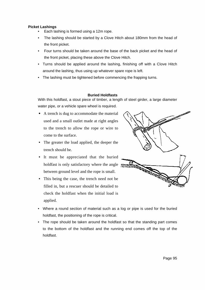
Page 95
Picket Lashings• Each lashing is formed using a 12m rope.
• The lashing should be started by a Clove Hitch about 180mm from the head of
the front picket.
• Four turns should be taken around the base of the back picket and the head of
the front picket, placing these above the Clove Hitch.
• Turns should be applied around the lashing, finishing off with a Clove Hitch
around the lashing, thus using up whatever spare rope is left.
• The lashing must be tightened before commencing the frapping turns.
Buried HoldfastsWith this holdfast, a stout piece of timber, a length of steel girder, a large diameter
water pipe, or a vehicle spare wheel is required.
• Where a round section of material such as a log or pipe is used for the buried
holdfast, the positioning of the rope is critical.
• The rope should be taken around the holdfast so that the standing part comes
to the bottom of the holdfast and the running end comes off the top of the
holdfast.
•••• A trench is dug to accommodate the material
used and a small outlet made at right angles
to the trench to allow the rope or wire to
come to the surface.
• The greater the load applied, the deeper the
trench should be.
• It must be appreciated that the buried
holdfast is only satisfactory where the angle
between ground level and the rope is small.
• This being the case, the trench need not be
filled in, but a rescuer should be detailed to
check the holdfast when the initial load is
applied.
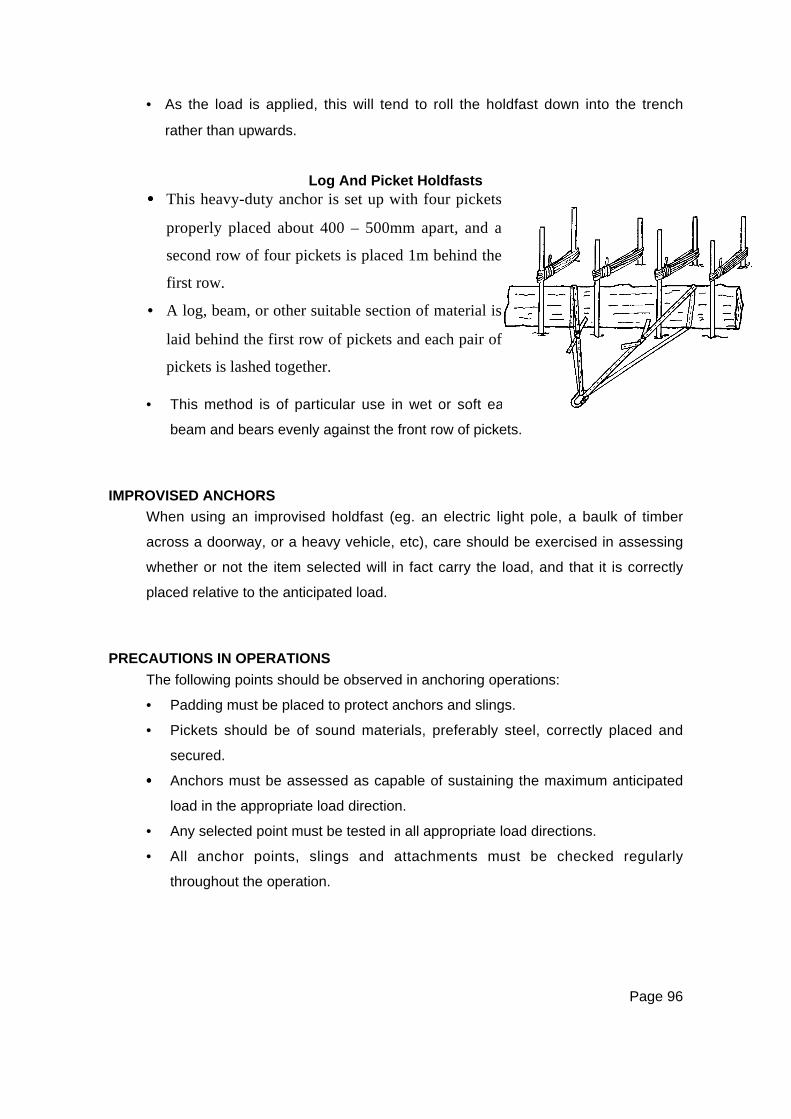
Page 96
• As the load is applied, this will tend to roll the holdfast down into the trench
rather than upwards.
Log And Picket Holdfasts
• This method is of particular use in wet or soft earth since the log acts as a
beam and bears evenly against the front row of pickets.
IMPROVISED ANCHORS
When using an improvised holdfast (eg. an electric light pole, a baulk of timber
across a doorway, or a heavy vehicle, etc), care should be exercised in assessing
whether or not the item selected will in fact carry the load, and that it is correctly
placed relative to the anticipated load.
PRECAUTIONS IN OPERATIONS
The following points should be observed in anchoring operations:
• Padding must be placed to protect anchors and slings.
• Pickets should be of sound materials, preferably steel, correctly placed and
secured.
•••• Anchors must be assessed as capable of sustaining the maximum anticipated
load in the appropriate load direction.
• Any selected point must be tested in all appropriate load directions.
• All anchor points, slings and attachments must be checked regularly
throughout the operation.
•••• This heavy-duty anchor is set up with four pickets
properly placed about 400 – 500mm apart, and a
second row of four pickets is placed 1m behind the
first row.
• A log, beam, or other suitable section of material is
laid behind the first row of pickets and each pair of
pickets is lashed together.
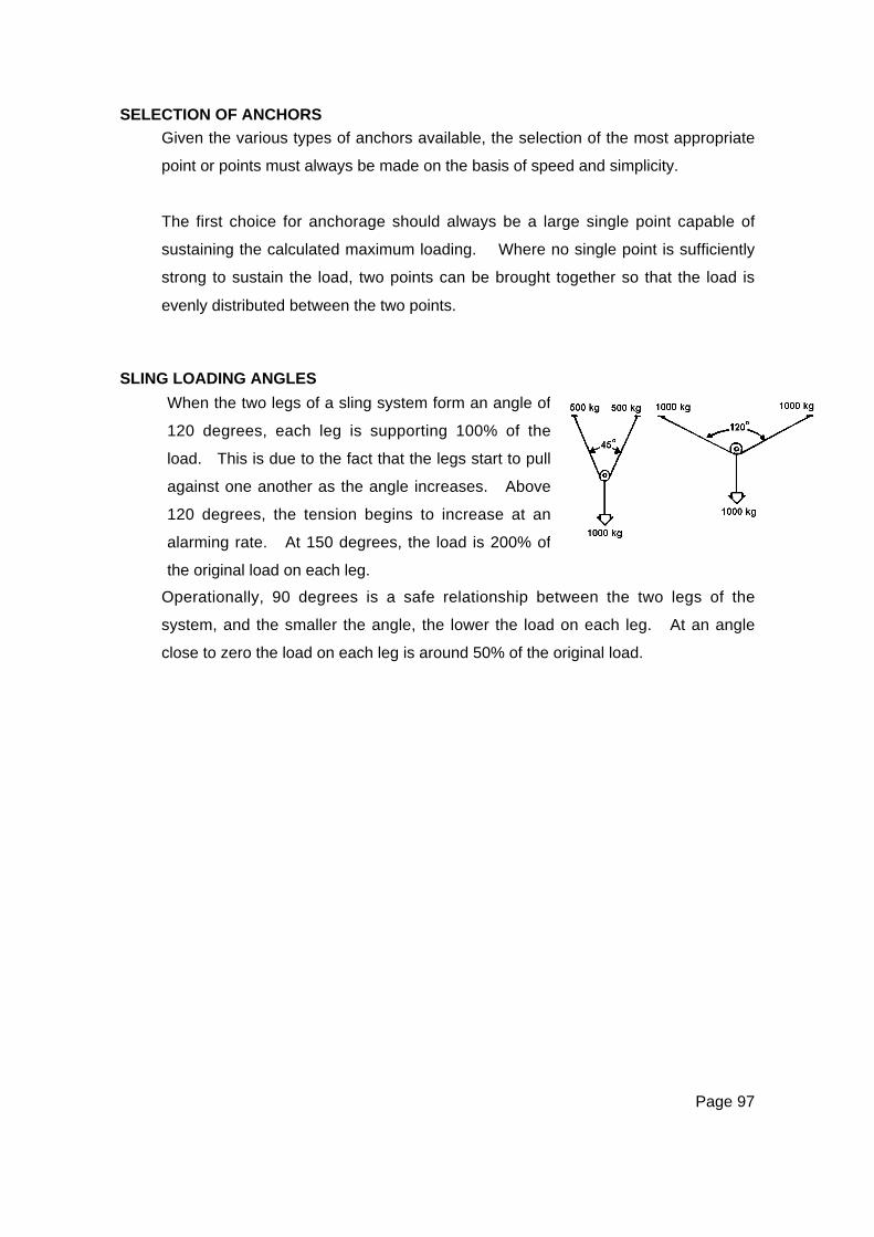
Page 97
SELECTION OF ANCHORS
Given the various types of anchors available, the selection of the most appropriate
point or points must always be made on the basis of speed and simplicity.
The first choice for anchorage should always be a large single point capable of
sustaining the calculated maximum loading. Where no single point is sufficiently
strong to sustain the load, two points can be brought together so that the load is
evenly distributed between the two points.
SLING LOADING ANGLES
Operationally, 90 degrees is a safe relationship between the two legs of the
system, and the smaller the angle, the lower the load on each leg. At an angle
close to zero the load on each leg is around 50% of the original load.
When the two legs of a sling system form an angle of
120 degrees, each leg is supporting 100% of the
load. This is due to the fact that the legs start to pull
against one another as the angle increases. Above
120 degrees, the tension begins to increase at an
alarming rate. At 150 degrees, the load is 200% of
the original load on each leg.
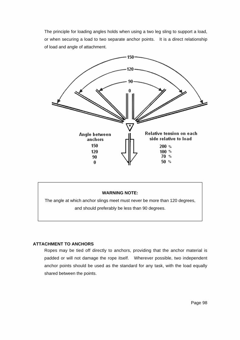
Page 98
The principle for loading angles holds when using a two leg sling to support a load,
or when securing a load to two separate anchor points. It is a direct relationship
of load and angle of attachment.
WARNING NOTE:
The angle at which anchor slings meet must never be more than 120 degrees,
and should preferably be less than 90 degrees.
ATTACHMENT TO ANCHORS
Ropes may be tied off directly to anchors, providing that the anchor material is
padded or will not damage the rope itself. Wherever possible, two independent
anchor points should be used as the standard for any task, with the load equally
shared between the points.

Page 99
Rescue anchors are most commonly set up with the load attached by means of
climbing tape slings and rescue rated Karabiner. In any single anchor point
system, two tape slings should be taken completely around the anchor, and
all four loop ends clipped into the Karabiner. Where multiple point systems
are set up, a single tape sling is acceptable for each point.
Heavy-duty anchor systems are set up using steel wire rope or webbing slings
taken around a padded anchor, and connected to the load by means of
appropriately rated shackles.
KARABINERS
Karabiners are manufactured from either high-tensile steel or alloy, and may have
either a plain opening gate, or one fitted with a screw locking device or autolocking
gate, which prevents the gate from accidental opening. Consequently, Karabiners
are referred to as snaplinks, screwgates, twistlocks, or autolocks.
NOTE: Auto-locking Karabiners are considered to be ‘Best Practice’ in
rescue situations.
Most manufacturers stamp the rated strength of the Karabiner into the metal for
easy reference. Rescue Karabiners should be of minimum rated strength of
2500kg.
Known as ‘karabs’, ‘biners’, or ‘snaplinks’ these are
the most common item of hardware used in vertical
rescue. They are normally a ‘D’ or modified ‘D’
shaped metal link, having a spring loaded opening
section (the gate) in one of the long sides. The
gate allows ropes and slings to be clipped into the
Karabiner for attachment purposes.
Page 100
WARNING NOTE:
Snaplink style Karabiners are NOT recommended for rescue.
As these devices are made of specialised steel or alloys, care should be taken not
to drop them or knock them on hard surfaces. Small stress points can be
introduced into the metal that may then cause deterioration of the device.
Accidental Gate OpeningThe main job of a Karabiner is to maintain its link with the other elements of the
rescue system. To do this, the Karabiner gate must remain securely closed. If it
does not, then the connecting elements will come apart and the system will fail.
There are several ways in which Karabiner gates may come open accidentally.
Among the most common situations are where:
• The Karabiner is pressed against an edge or surface, forcing the gate open.
• A rope or section of tape is pulled across the Karabiner gate, forcing it open.
Concerns With Screwgate KarabinersAny Karabiner that regularly becomes unlocked without apparent reason must be
withdrawn from service. Screw gate Karabiners are designed to be locked only to
finger tightness. In their concern for safety, and in some anxiety, people will tend
to over-tighten a Karabiner gate, and then be unable to unlock it. This most
commonly occurs when the gate is tightened while the Karabiner is under load,
and unlocking it is readily accomplished by again subjecting it to a similar load.
Karabiner UsageKarabiners are designed to be loaded along the major axis or spine. As
previously stated, the gate is the weakest point of a Karabiner, and any side
loading places an unnatural force on the Karabiner, severely reduces its strength,
and may cause it to fail.

Page 101
With some Karabiner designs, vibration can cause the gate locking sleeve to
unscrew. Karabiners should always be used in a manner which will ensure that
gravity will keep the sleeve in place.
WARNING NOTE:
Maximum strength is only achieved when the Karabiner gate is locked.
Karabiners must not be used unless the gate is properly closed and locked.
SHACKLES
WARNING NOTE:
Only the shackle pin should be used to secure the shackle.
The practice of replacing the proper pin with a nut and bolt is highly dangerous
and may cause the failure of the shackle.
There are two principal types of shackle: ‘D’ and ‘Bow’. With ‘D’
being the most commonly used in the rescue environment.
Almost all are made from a plain round steel bar and all are
secured by a round section steel pin, and all should comply with
New Zealand Standards.
The pin is located through one eye of the shackle and screws
directly into the other (threaded) eye to secure the attachment in
the shackle.
Shackles must be selected which are large enough to accept the
slings or other attachments, and which are appropriately rated for
the loading and the task.

Page 102
Safety In OperationThe following safety points should be noted:
• Shackles or pins that are worn more than 10% of the original diameter must be
removed from service and destroyed.
• Shackles or pins that have been bent, strained, deformed, or damaged must
not be used. They should be removed from service and destroyed.
• Screw shackle pins must be properly tightened and either moused or
monitored to ensure that the pins do not unscrew under load.
• Always use shackles of the correct size and shape for the task.
SAFETY SUMMARY
The three-point safety plan recommended for all anchorage operations is as
follows:
1. Select points which are suitable, strong and safe, and check angles between
anchors.
2. Ensure all connections are properly made and checked.
3. Monitor the anchor system at all times.
Page 103
CHAPTER EIGHTLADDERS
INTRODUCTION
Ladders are readily available at most rescue sites and during a disaster may be
used for improvised rescue techniques. It must be remembered however, that
ladders have been constructed to be used in a specified load bearing position, and
should normally be used in accordance with AN/NZS Standards.
CONSTRUCTION
Ladders come in a variety of styles, lengths, and materials. Aluminium, timber,
and fibreglass are the three most commonly in use.
EXTENSION LADDERS
Extension ladders are commonly in two sections, with the upper section sliding on
and between the stiles of the lower section. Latching devices are fitted to the
lower end of the upper section and operate on a movable shaft. Hauling ropes
are taken through a sheave fixed near the top of the lower section, brought down,
and fastened to hooks or cleats at the bottom of the upper section. One cleat is
attached to the latching device thus providing an endless line by means of which
the top section can be extended and the latching devices, which are mounted on
the upper section, can be engaged or released.
To easily distinguish them in the dark, the stiles of the top section should bear a
white line to indicate the limit of safety when extended for use.
Timber ladders are strengthened on the underside of the stiles by galvanised wire
or fibreglass which is stretched tautly in the groove along the edge of the strings
being secured top and bottom.
Timber ladders are further strengthened by cross ties from stile to stile at intervals.
Ladders should not be painted as paint could hide defects. A small section, at
each end, may be painted for identification purposes. Timber ladders may be
treated with linseed oil.
Defective ladders must be withdrawn from service and labelled: ‘Dangerous – Do not
use’, and either repaired or destroyed as soon as possible.
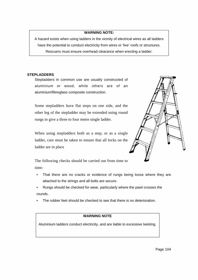
Page 104
WARNING NOTE:
A hazard exists when using ladders in the vicinity of electrical wires as all ladders
have the potential to conduct electricity from wires or ‘live’ roofs or structures.
Rescuers must ensure overhead clearance when erecting a ladder.
STEPLADDERS
• That there are no cracks or evidence of rungs being loose where they are
attached to the strings and all bolts are secure.
• Rungs should be checked for wear, particularly where the pawl crosses the
rounds.
• The rubber feet should be checked to see that there is no deterioration.
WARNING NOTE
Aluminium ladders conduct electricity, and are liable to excessive twisting.
Stepladders in common use are usually constructed of
aluminium or wood, while others are of an
aluminium/fibreglass composite construction.
Some stepladders have flat steps on one side, and the
other leg of the stepladder may be extended using round
rungs to give a three to four metre single ladder.
When using stepladders both as a step, or as a single
ladder, care must be taken to ensure that all locks on the
ladder are in place
The following checks should be carried out from time to
time:
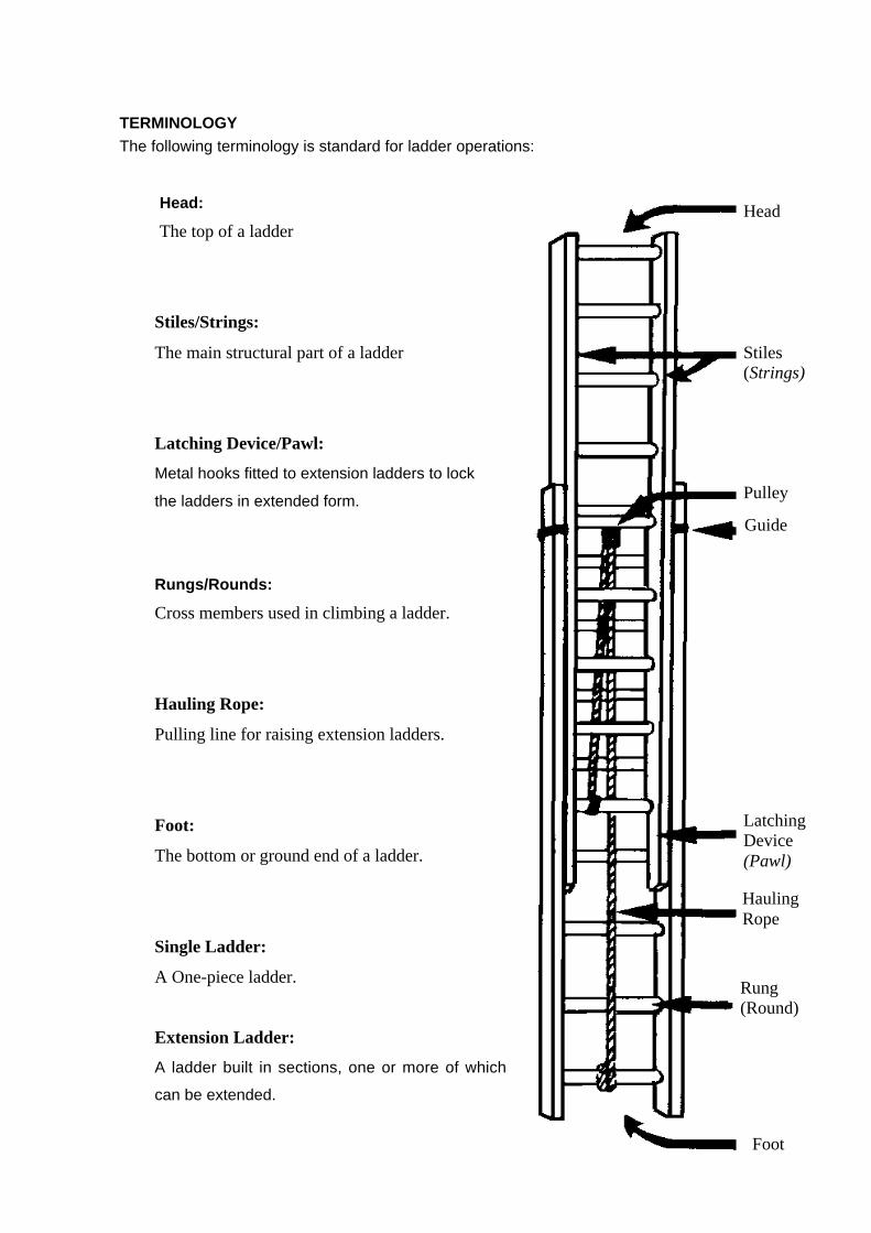
Page 105
TERMINOLOGY
The following terminology is standard for ladder operations:
Foot
LatchingDevice(Pawl)
HeadHead:
The top of a ladder
Stiles/Strings:
The main structural part of a ladder
Latching Device/Pawl:
Metal hooks fitted to extension ladders to lock
the ladders in extended form.
Rungs/Rounds:
Cross members used in climbing a ladder.
Hauling Rope:
Pulling line for raising extension ladders.
Foot:
The bottom or ground end of a ladder.
Single Ladder:
A One-piece ladder.
Extension Ladder:
A ladder built in sections, one or more of which
can be extended.
Rung(Round)
HaulingRope
Guide
Pulley
Stiles(Strings)
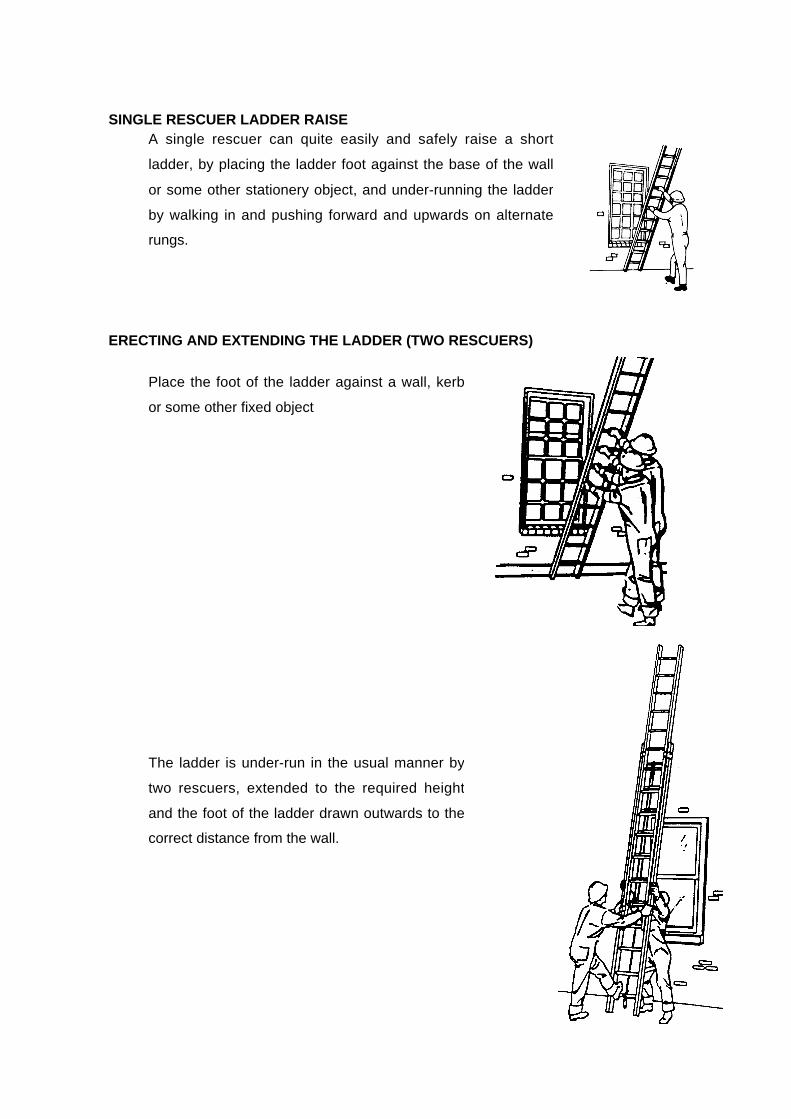
Page 106
SINGLE RESCUER LADDER RAISE
ERECTING AND EXTENDING THE LADDER (TWO RESCUERS)
A single rescuer can quite easily and safely raise a short
ladder, by placing the ladder foot against the base of the wall
or some other stationery object, and under-running the ladder
by walking in and pushing forward and upwards on alternate
rungs.
Place the foot of the ladder against a wall, kerb
or some other fixed object
The ladder is under-run in the usual manner by
two rescuers, extended to the required height
and the foot of the ladder drawn outwards to the
correct distance from the wall.

Page 107
ERECTING AND EXTENDING THE LADDER (THREE RESCUERS)
Ideally three rescuers are required to form a ladder team.
• One person is responsible for the foot of the ladder, both in
carrying and positioning where necessary.
• The others support the uppermost stile of the ladder on
their shoulders.
• On arrival at the site, one person places the foot of the
ladder with the reinforcing wires uppermost (if not
uppermost, turn ladder over) as near as possible to its
required position and anchors it by ‘footing’. The others,
working on their respective sides, raise the ladder from the
underneath side to the vertical position assisted by the first
person.
• The others face the ladder, each ‘footing’ it, and then the
first person, pulling on the hauling ropes, extends the
ladder to the required height ensuring that the latching
device is properly engaged on the rung.
• The ladder is then laid back by the first person, who walks
backward until the top of the ladder comes to rest where
required is: against sill, wall etc.
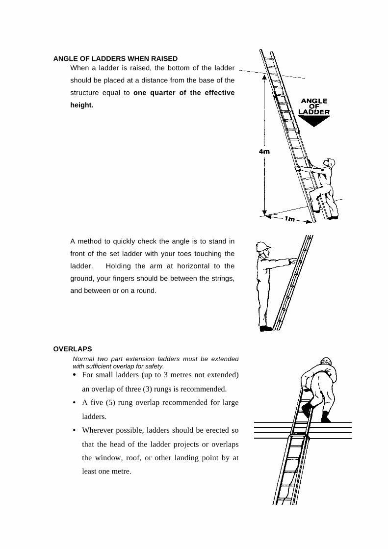
Page 108
ANGLE OF LADDERS WHEN RAISED
OVERLAPS
When a ladder is raised, the bottom of the ladder
should be placed at a distance from the base of the
structure equal to one quarter of the effective
height.
A method to quickly check the angle is to stand in
front of the set ladder with your toes touching the
ladder. Holding the arm at horizontal to the
ground, your fingers should be between the strings,
and between or on a round.
Normal two part extension ladders must be extendedwith sufficient overlap for safety.•••• For small ladders (up to 3 metres not extended)
an overlap of three (3) rungs is recommended.
• A five (5) rung overlap recommended for large
ladders.
• Wherever possible, ladders should be erected so
that the head of the ladder projects or overlaps
the window, roof, or other landing point by at
least one metre.
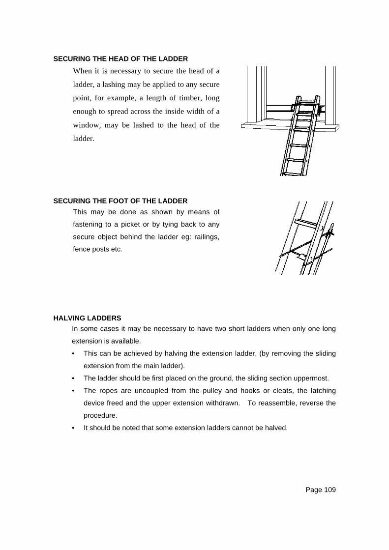
Page 109
SECURING THE HEAD OF THE LADDER
SECURING THE FOOT OF THE LADDER
HALVING LADDERS
In some cases it may be necessary to have two short ladders when only one long
extension is available.
• This can be achieved by halving the extension ladder, (by removing the sliding
extension from the main ladder).
• The ladder should be first placed on the ground, the sliding section uppermost.
• The ropes are uncoupled from the pulley and hooks or cleats, the latching
device freed and the upper extension withdrawn. To reassemble, reverse the
procedure.
• It should be noted that some extension ladders cannot be halved.
When it is necessary to secure the head of a
ladder, a lashing may be applied to any secure
point, for example, a length of timber, long
enough to spread across the inside width of a
window, may be lashed to the head of the
ladder.
This may be done as shown by means of
fastening to a picket or by tying back to any
secure object behind the ladder eg: railings,
fence posts etc.
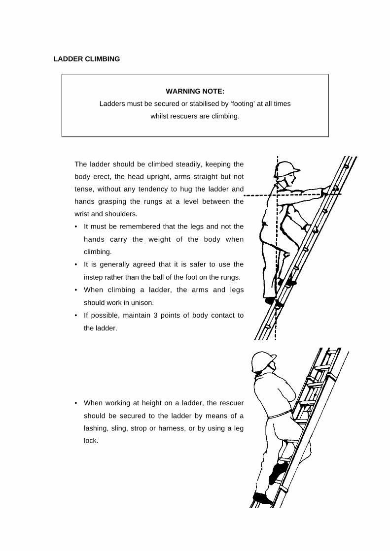
Page 110
LADDER CLIMBING
WARNING NOTE:
Ladders must be secured or stabilised by ‘footing’ at all times
whilst rescuers are climbing.
The ladder should be climbed steadily, keeping the
body erect, the head upright, arms straight but not
tense, without any tendency to hug the ladder and
hands grasping the rungs at a level between the
wrist and shoulders.
• It must be remembered that the legs and not the
hands carry the weight of the body when
climbing.
• It is generally agreed that it is safer to use the
instep rather than the ball of the foot on the rungs.
• When climbing a ladder, the arms and legs
should work in unison.
• If possible, maintain 3 points of body contact to
the ladder.
• When working at height on a ladder, the rescuer
should be secured to the ladder by means of a
lashing, sling, strop or harness, or by using a leg
lock.
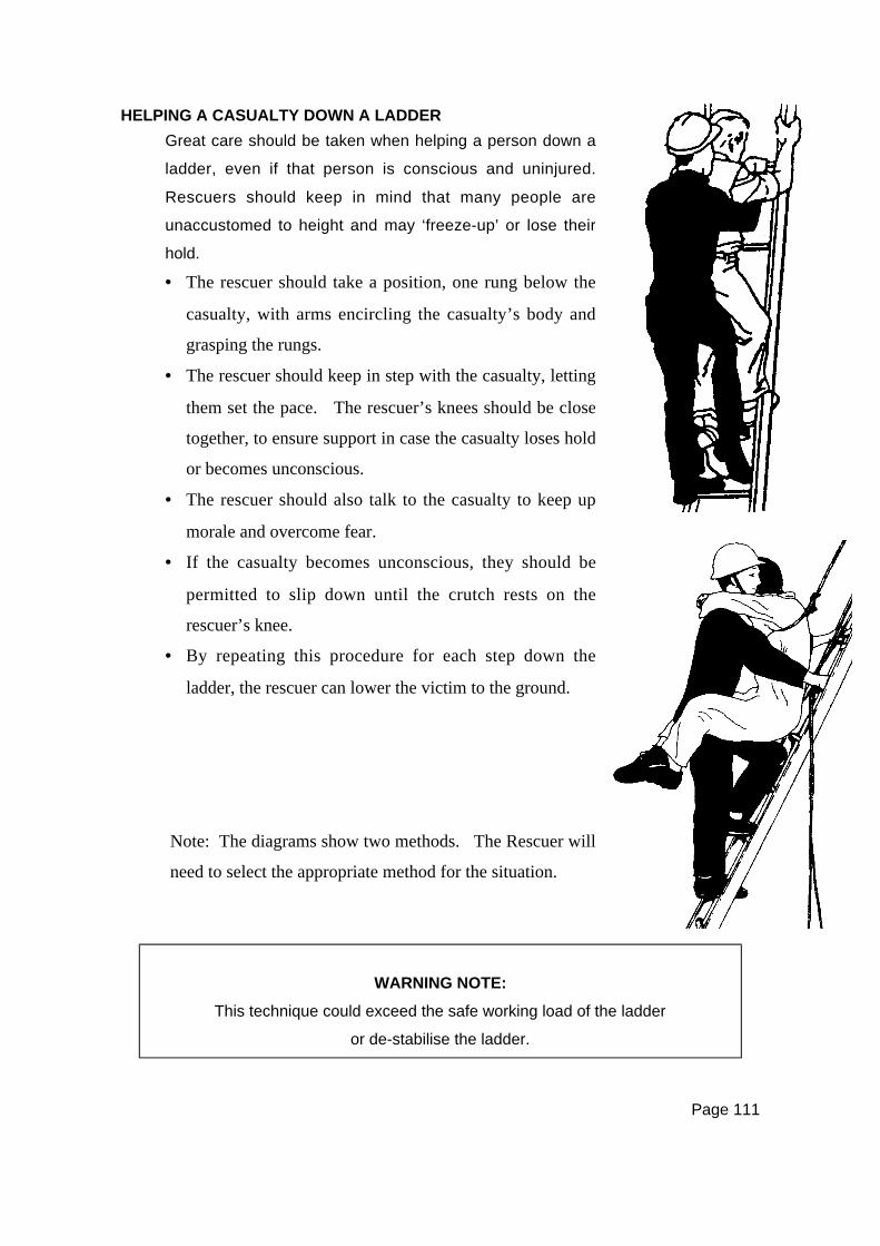
Page 111
HELPING A CASUALTY DOWN A LADDER
WARNING NOTE:
This technique could exceed the safe working load of the ladder
or de-stabilise the ladder.
Great care should be taken when helping a person down a
ladder, even if that person is conscious and uninjured.
Rescuers should keep in mind that many people are
unaccustomed to height and may ‘freeze-up’ or lose their
hold.
• The rescuer should take a position, one rung below the
casualty, with arms encircling the casualty’s body and
grasping the rungs.
• The rescuer should keep in step with the casualty, letting
them set the pace. The rescuer’s knees should be close
together, to ensure support in case the casualty loses hold
or becomes unconscious.
• The rescuer should also talk to the casualty to keep up
morale and overcome fear.
• If the casualty becomes unconscious, they should be
permitted to slip down until the crutch rests on the
rescuer’s knee.
• By repeating this procedure for each step down the
ladder, the rescuer can lower the victim to the ground.
Note: The diagrams show two methods. The Rescuer will
need to select the appropriate method for the situation.

Page 112
MAINTENANCE AND TESTING
Extension ladders must be regularly and carefully checked for damage or defects,
in accordance with the relevant Standards. Particular attention must be paid to
those ladders that are stored on vehicle roof racks and thereby exposed to the
weather regularly.
The ladder should be visually inspected for cracks in the timber, the security of the
rungs and reinforcing wires, and for general appearance.
Pulleys, latching devices and extension guides should be checked for lubrication
and security, and the latching device pivot points and pulleys lubricated as
necessary. Hauling ropes should be checked and replaced as necessary.
Ladders should never be painted as the paint can cover quite serious cracks and
defects. Better that timber ladders be left in a natural condition, and regularly
oiled with linseed oil, which will keep the ladder flexible, and prevent water damage
or rot.
Page 113
CHAPTER NINECASUALTY HANDLING TECHNIQUES
INTRODUCTION
Rescues will be conducted under almost every conceivable adverse condition.
The method used for casualty removal will depend on the location of the casualty
and the type of injury sustained. In some rescue operations, casualties will have
to be lowered from the upper floors of buildings; in others, hoisted from below
through holes in floors, or removed by a combination of those techniques. Where
casualties are handled by rescue personnel, care must be taken to ensure that
further aggravation of injuries does not occur.
All rescuers must be aware that the safety of the casualty is paramount even when
immediate evacuation from a hazardous environment is necessary.
A careful assessment must be made of the casualties’ injuries, condition, and
possible entrapment, and a final check must be made to ensure that the casualty is
actually ready to move and is not caught or entangled in some unseen object.
WARNING NOTE:
The importance of first aid training cannot be over-stated.
All rescue personnel must hold a current first aid qualification.
After removal, many casualties will have to be carried over piles of debris and
uneven ground before being handed over to the ambulance service or first aid
station. Whilst speed of removal is important, it must be consistent with safety and
proper handling to prevent further injury.
Page 114
The method used will depend on the immediate situation, the condition of
casualties, types of injuries, and available equipment. Rescue leaders should
conduct frequent exercises in the removal of casualties, using live people as
casualties to give team members understanding and confidence in the various
methods, enabling them to make decisions promptly in times of emergency.
As important as learning methods; rescuers should experience the physical effort
required in transporting casualties, either by stretchers or by some improvised
method. The transportation of casualties over long distances is a very tiring task
and requires fit personnel.
TRIAGE
Where multiple casualties need attention, the rescuer will be required to select
casualties for treatment and rescue by order of priority. This selection or sorting
of casualties is known as Triage.
Rescuers may be called upon to perform the triage role at a rescue site as a
specific task, or this may be a part of the overall reconnaissance element of a
rescue.
While moving fairly quickly from casualty to casualty, the rescuer performing triage
must:
• Quickly assess the condition of casualties and label them.
• Place any unconscious person in a lateral recovery position – care for airway,
breathing, and circulation.
• Temporarily control any serious bleeding – by the use of bystanders or other
rescuers as necessary.
• Choose the casualties with the greatest chance of survival.
It must be noted that it will sometimes be necessary to treat and rescue casualties
of relatively low priority in order to access and clear the way for treatment of high
priority casualties. Additionally, the principle of ‘remove the casualty from the
risk or remove the risk from the casualty’ should be adopted where a site
hazard presents a risk to casualties being treated prior to rescue.
Page 115
CASUALTY SORTING
Priorities are displayed using a colour code system:
•••• Red
Those victims who need immediate advanced medical treatment (within 1 hour)
to survive. These victims would have first priority for transport to a medical
facility, if available.
•••• Yellow
These victims have serious injuries, but are not life threatening. They will
survive without advanced medical treatment and their situation can be
maintained through proper basic emergency care.
•••• Green
Minor injuries that can be dealt with by first aid, or can wait for some time without
treatment.
•••• Black
Deceased, or who are unlikely to survive given the situation.
WARNING NOTE
These colour codes may constantly change, as the assessment of the
casualties and their injuries is an ongoing process.
The victim’s colour code may change as the situation changes (e.g. the
availability of transport, medical supplies, etc).
In a major incident, be prepared to wait some time without either advanced
care on-site, or transport to an appropriate facility.

Page 116
CASUALTY TAGS
Any tagging system may be used for casualties during a disaster, providing the
method undertaken is easily understood by all of those concerned with its use.
The type of casualty tag to be used during a disaster should, where possible, be
predetermined and arrangements made to hold adequate stocks of tags for use.
STRETCHERS
The Four categories of stretcher in most common use are:
• Folding or Pole stretcher
• Basket stretcher—incorrectly referred to as the Stokes Litter, or Ferno-
Washington.
• Wrap-around stretchers
• Board Rescue stretchers.

Page 117
FOLDING OR POLE STRETCHERS
WARNING NOTE
These stretchers are not suitable for lowers,
and are only appropriate for casualty movement on the flat.
The folding stretcher must be set up, as follows
before a casualty can be transferred to it:
• Unfasten the straps that hold the stretcher
closed.
• Spread open the stretcher and lock the
spreaders in place by pushing on each bar
with your foot, until it locks into place.
• Do not use your hands as they can be
pinched by the hinges.
• Where it is possible that the centre hinge of
the spreader bar may be snagged, causing the
hinge to unlock and collapse the stretcher, a
securing rope should be used.
• A short length of rope can be tied from one
stretcher handle to the centre hinge and then to
the other stretcher handle in ‘V’ pattern.
• The Clove Hitch or Round Turn and Two Half
Hitches is ideal for all three knots of this rig.
Page 118
BLANKETING THE STRETCHER
Before a casualty is placed on a stretcher, it should be covered with a blanket so
that no contact is made with the canvas bed portion. This adds to comfort, keeps
the casualty warm, and to a large degree helps immobilise any fractures that may
have been sustained. Depending on the weather, and the supply of available
blankets, one or two blankets can be used. In very warm weather a cotton bed
sheet or sheets may be used instead of blankets.
Single Blanket Method
• Lay one open blanket diagonally down the
stretcher with the corner of the blanket in the
centre of the top of the stretcher, and about
150mm overlapping.
• Place the casualty on the blanket with the
head level with the top.
• Fold over and tuck in the lower half of the
blanket.
• Do likewise with the top half.

Page 119
Blanketing – Lateral/Recovery Position
• Roll a blanket end to end and position it on the stretcher so that the roll is used
to pad the patient’s back.
• A second blanket is placed on the stretcher in a similar manner with the rolled
portion on the opposite side, and the blanket folded over the patient and tucked
under the first roll.
In addition to warmth, comfort, and
immobilisation, the blanket is used for
padding to keep the patient in the required
lateral/recovery position.
The following is the recommended method:
Page 120
LOADING A STRETCHER
• Loading a stretcher is an important part of casualty handling.
• Correct methods are essential for the well being of the casualty to prevent
aggravation of injuries.
• Final checks must be made by hand to ensure that a casualty is actually free to
lift before a lift is executed.
WARNING NOTE:
The casualty’s head and neck must be supported at all times.
The Four Rescuer Method
When using four rescuers to load a stretcher and wherespinal injuries are not suspected, the following method canbe used:•••• The stretcher is made ready and placed near the
casualty’s head or feet.
• The leader details three others to kneel down on one
knee on one side of the casualty (casualty lying flat on
back). They all have the knee up closest to the
casualty’s head.
• The leader kneels near the casualty’s hip on the opposite
side to the three others and eases the casualty on to one
side.
• The other three place their hands and arms underneath
the casualty and the leader lowers the casualty onto their
arms.
• The leader gives the order: Prepare To Lift and, if no
one dissents, follows it with: Lift, whereupon all four
lift.
• If necessary, the casualty can be briefly supported on the
rescuers knees. The leader then places the stretcher
under the casualty.
• Final orders are: Prepare To Lower, then: Lower.
• The three rescuers, assisted by the leader, lower the
casualty on to the stretcher.
Page 121
Blanket Lift (Four Or Six Rescuers)
• The sides of the blanket are rolled up close to the casualty’s body to provide
handgrips for the bearers.
• On the order from the leader, the casualty is lifted waist high, and carried to the
stretcher.
• On the order from the leader, the casualty is lowered onto the stretcher.
• The blanketing is then completed with one blanket, leaving the lifting blanket in
position.
• This ‘blanket carry’ can also be used as an improvised stretcher for carries
over moderate distances.
WARNING NOTE:
Suspected spinal injured casualties can be safely transported by this method
with correct immobilisation of the spine and with particular attention paid
to the head and neck.
This is an effective method for loading or moving a
casualty in a confined space.
• Make a stretcher ready using one blanket.
• Roll a blanket lengthways for half of its width
and lay the rolled section along the side of the
casualty (casualty flat on back).
• The leader then directs two (or three) rescuers
to kneel down on each side of the casualty.
• The rescuers on one side ease the casualty over
on one side and the rolled section of the blanket
is pushed well underneath the casualty.
• With the rolled up section of the blanket now
under the centre of the casualty, the casualty is
eased over in the opposite direction and the
blanket is unrolled. The casualty should now be
lying flat on their back.

Page 122
Clothing Lift (Three Rescuers)
• Roll the casualty’s clothes together along the centre of the body.
• Three rescuers take up the position on the opposite side of the casualty to the
stretcher and position their hands.
• The normal commands are given (Prepare To Lift, etc) and the casualty is
gently placed on the stretcher.
Webbing Bands (Five Rescuers)
This is an emergency method which can be
used when the casualty’s injuries are not too
severe, and time is critical.
• Blanket a stretcher and place it close to
the side of the casualty.
• Tie the casualty’s hands together with a
triangular bandage or similar material if
unconscious.
In some cases it may be necessary to transport a
casualty some distance to a place where a stretcher
can be loaded. Webbing bands can greatly assist
this operation. While there are many configurations
that can be used, one suggestion is:
• The bands are placed in position by pushing the
long steel handle under the natural body hollows
and see-sawing the bands into the requires
position, i.e. under the buttocks and shoulders.
• After bands are correctly positioned, the handles of
each band are centred above the middle of the
casualty and the five rescuers take up position.
Page 123
Specialist Lifting/Loading Devices Specialist lifting/loading/extraction devices such as timber or synthetic spinal
boards, scoop stretchers, and spinal immobilisation devices or harnesses are
readily available from rescue equipment suppliers.
These devices should always be used in compliance with manufacturers’
specifications and recommendations, and following appropriate specialist training.
LASHING THE CASUALTY TO THE STRETCHER
In many cases, casualties will have to be firmly secured to the stretcher to enable it
to be handled in different places. No hard or fast rule can be laid down as to
when the casualty should or should not be lashed in, however, the nature of the
rescue should in itself provide the answer. If in doubt, lash the casualty in.
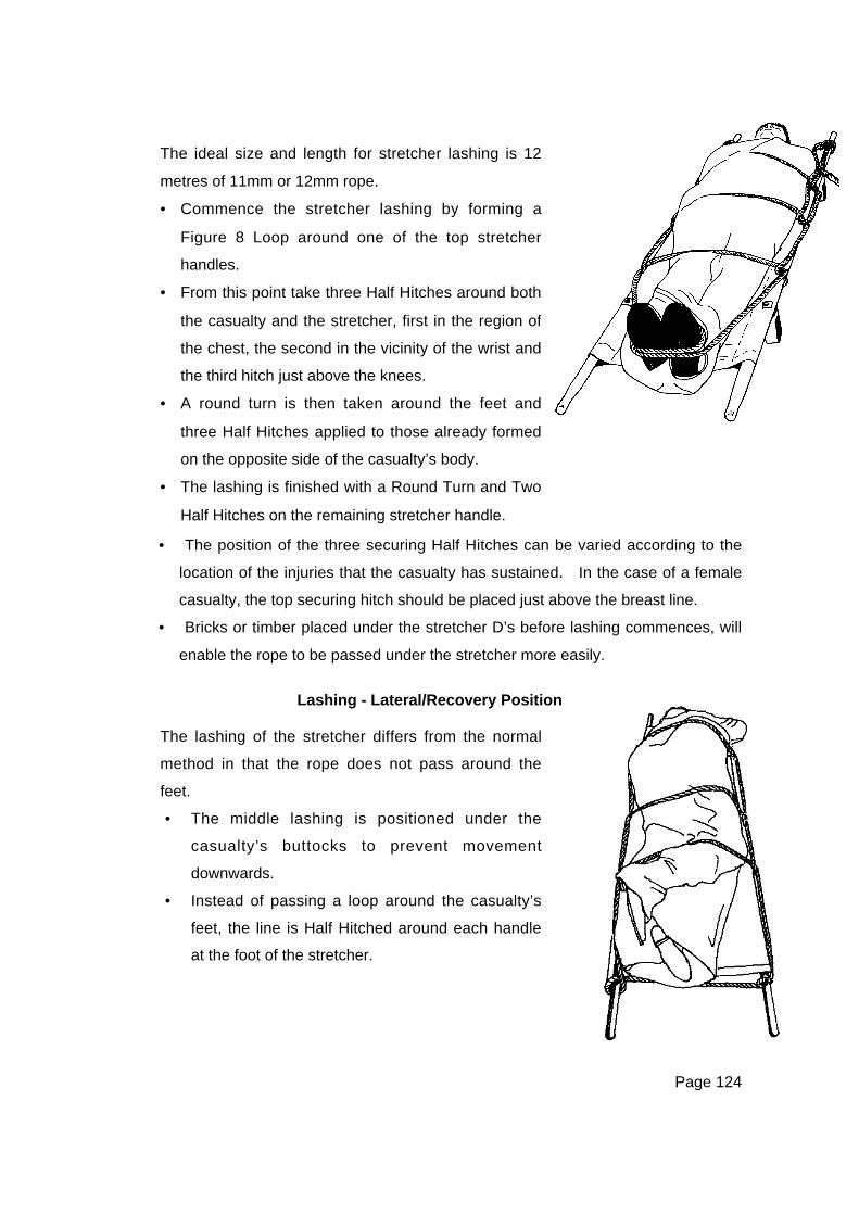
Page 124
• The position of the three securing Half Hitches can be varied according to the
location of the injuries that the casualty has sustained. In the case of a female
casualty, the top securing hitch should be placed just above the breast line.
• Bricks or timber placed under the stretcher D’s before lashing commences, will
enable the rope to be passed under the stretcher more easily.
Lashing - Lateral/Recovery Position
The ideal size and length for stretcher lashing is 12
metres of 11mm or 12mm rope.
• Commence the stretcher lashing by forming a
Figure 8 Loop around one of the top stretcher
handles.
• From this point take three Half Hitches around both
the casualty and the stretcher, first in the region of
the chest, the second in the vicinity of the wrist and
the third hitch just above the knees.
• A round turn is then taken around the feet and
three Half Hitches applied to those already formed
on the opposite side of the casualty’s body.
• The lashing is finished with a Round Turn and Two
Half Hitches on the remaining stretcher handle.
The lashing of the stretcher differs from the normal
method in that the rope does not pass around the
feet.
• The middle lashing is positioned under the
casualty’s buttocks to prevent movement
downwards.
• Instead of passing a loop around the casualty’s
feet, the line is Half Hitched around each handle
at the foot of the stretcher.

Page 125
BOARD RESCUE STRETCHERS
WARNING NOTE:
A rope lashing system should be used at all times other than when
the stretcher is moved over smooth and flat ground.
WARNING NOTE
Care must be taken if this stretcher is used for lowering
as the high centre of gravity can cause the stretcher to invert,
particularly when using the two-point suspension method.
Many organisations have Board Rescue
Stretchers available. This type of
stretcher has a number of advantages for
the rescue environment:
• Providing protection for the patient
from underneath.
• A number of handholds.
• Relatively inexpensive.
• This stretcher is suitable for patient
transport and some rescue techniques.
• A footplate is usually used to prevent
the patient sliding downwards if the
stretcher is tilted towards the vertical
position.

Page 126
Board Rescue Stretcher Lashing
NOTE: Some Board Rescue Stretchers have runners underneath and some
runners have slots in them for the rope to pass through. This has the advantage
of minimising ropes being scraped on the ground or building edges.
• Form a hitch by passing the line between the board and where the line passes
under the board. Tighten gently.
• This is repeated across the casualty’s wrists and again just above the
casualty’s knees.
• A complete round turn is taken around the feet.
• The rope is then taken up the other side of the board forming hitches on each
turn of the lashing.
• Complete with a round turn and 2 Half Hitches on the handhold opposite where
the lashing was started.
The patient should be lashed to the Board Rescue
Stretcher whenever it is going to be lowered. This may
also be necessary if carrying the patient in rough or
difficult terrain eg: rubble, confined spaces, and the
stretcher does not come with webbing or nylon straps.
A 12m rescue line is used to lash the Board Rescue
Stretcher.
The process is as follows:
• Begin with a Rethreaded Figure 8 through the top
most handhold or hole (depending on the design of
the stretcher this may be on the top or bottom edge,
or along the sides).
• Pass the line down the side of the board.
• Take a complete turn under the board and back
across the casualty’s chest.
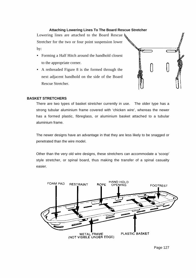
Page 127
Attaching Lowering Lines To The Board Rescue Stretcher
BASKET STRETCHERS
There are two types of basket stretcher currently in use. The older type has a
strong tubular aluminium frame covered with ‘chicken wire’, whereas the newer
has a formed plastic, fibreglass, or aluminium basket attached to a tubular
aluminium frame.
The newer designs have an advantage in that they are less likely to be snagged or
penetrated than the wire model.
Other than the very old wire designs, these stretchers can accommodate a ‘scoop’
style stretcher, or spinal board, thus making the transfer of a spinal casualty
easier.
Lowering lines are attached to the Board Rescue
Stretcher for the two or four point suspension lower
by:
• Forming a Half Hitch around the handhold closest
to the appropriate corner.
• A rethreaded Figure 8 is the formed through the
next adjacent handhold on the side of the Board
Rescue Stretcher.
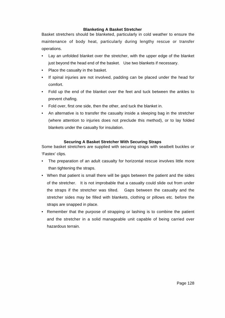
Page 128
Blanketing A Basket StretcherBasket stretchers should be blanketed, particularly in cold weather to ensure the
maintenance of body heat, particularly during lengthy rescue or transfer
operations.
• Lay an unfolded blanket over the stretcher, with the upper edge of the blanket
just beyond the head end of the basket. Use two blankets if necessary.
• Place the casualty in the basket.
• If spinal injuries are not involved, padding can be placed under the head for
comfort.
• Fold up the end of the blanket over the feet and tuck between the ankles to
prevent chafing.
• Fold over, first one side, then the other, and tuck the blanket in.
• An alternative is to transfer the casualty inside a sleeping bag in the stretcher
(where attention to injuries does not preclude this method), or to lay folded
blankets under the casualty for insulation.
Securing A Basket Stretcher With Securing StrapsSome basket stretchers are supplied with securing straps with seatbelt buckles or
‘Fastex’ clips.
• The preparation of an adult casualty for horizontal rescue involves little more
than tightening the straps.
• When that patient is small there will be gaps between the patient and the sides
of the stretcher. It is not improbable that a casualty could slide out from under
the straps if the stretcher was tilted. Gaps between the casualty and the
stretcher sides may be filled with blankets, clothing or pillows etc. before the
straps are snapped in place.
• Remember that the purpose of strapping or lashing is to combine the patient
and the stretcher in a solid manageable unit capable of being carried over
hazardous terrain.
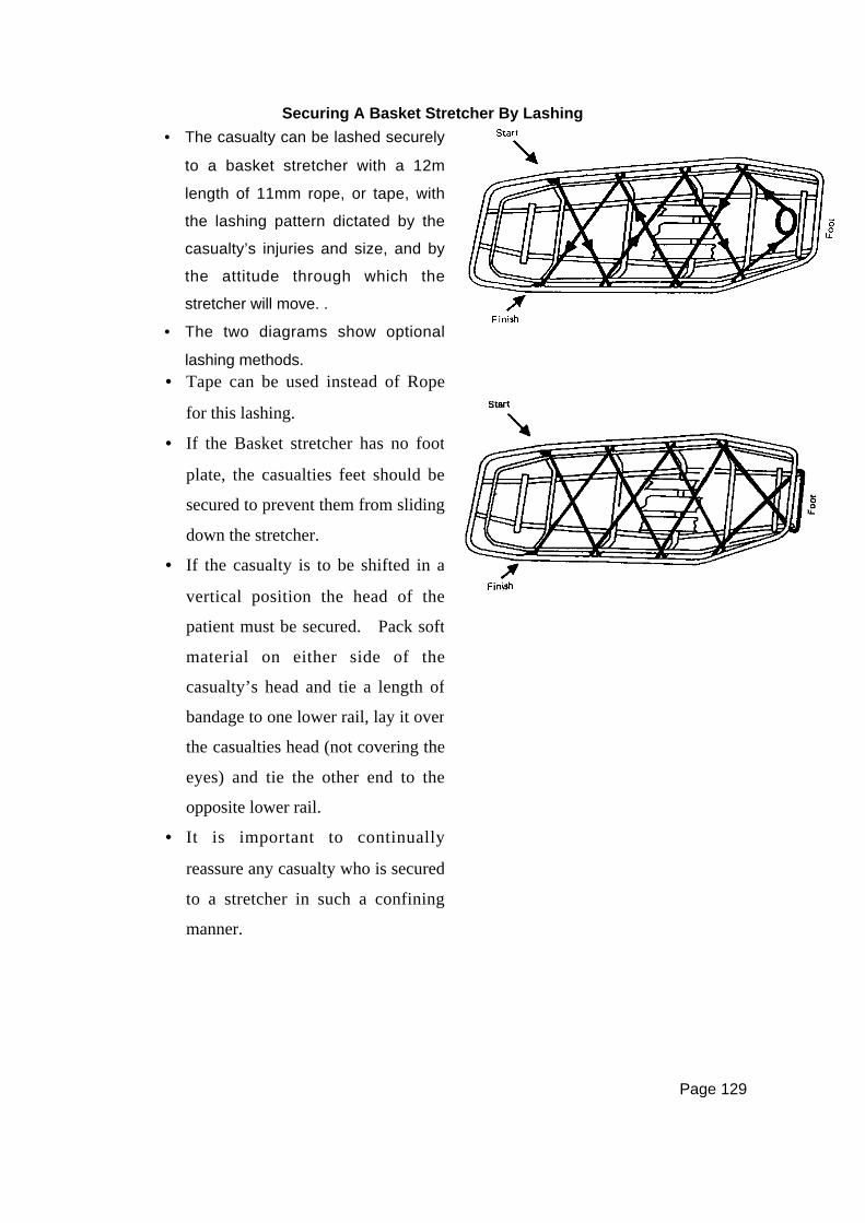
Page 129
Securing A Basket Stretcher By Lashing
• The casualty can be lashed securely
to a basket stretcher with a 12m
length of 11mm rope, or tape, with
the lashing pattern dictated by the
casualty’s injuries and size, and by
the attitude through which the
stretcher will move. .
• The two diagrams show optional
lashing methods.• Tape can be used instead of Rope
for this lashing.
• If the Basket stretcher has no foot
plate, the casualties feet should be
secured to prevent them from sliding
down the stretcher.
• If the casualty is to be shifted in a
vertical position the head of the
patient must be secured. Pack soft
material on either side of the
casualty’s head and tie a length of
bandage to one lower rail, lay it over
the casualties head (not covering the
eyes) and tie the other end to the
opposite lower rail.
• It is important to continually
reassure any casualty who is secured
to a stretcher in such a confining
manner.
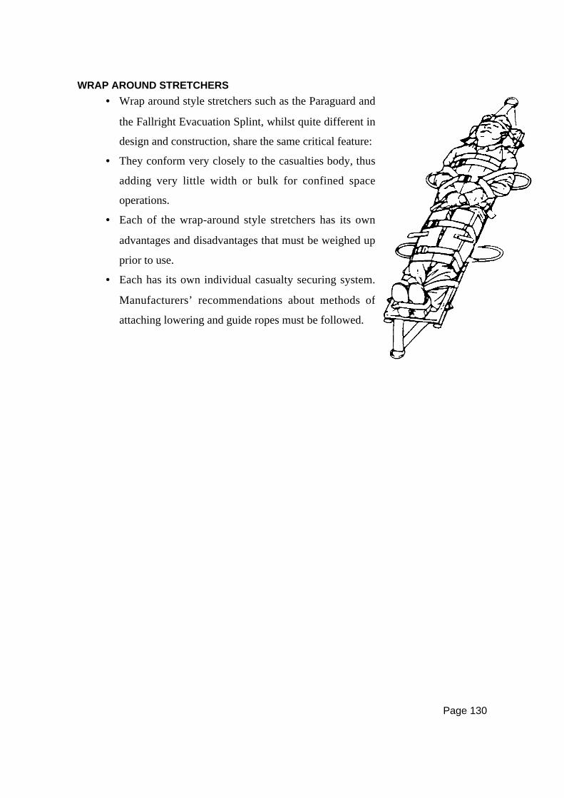
Page 130
WRAP AROUND STRETCHERS
• Wrap around style stretchers such as the Paraguard and
the Fallright Evacuation Splint, whilst quite different in
design and construction, share the same critical feature:
• They conform very closely to the casualties body, thus
adding very little width or bulk for confined space
operations.
• Each of the wrap-around style stretchers has its own
advantages and disadvantages that must be weighed up
prior to use.
• Each has its own individual casualty securing system.
Manufacturers’ recommendations about methods of
attaching lowering and guide ropes must be followed.
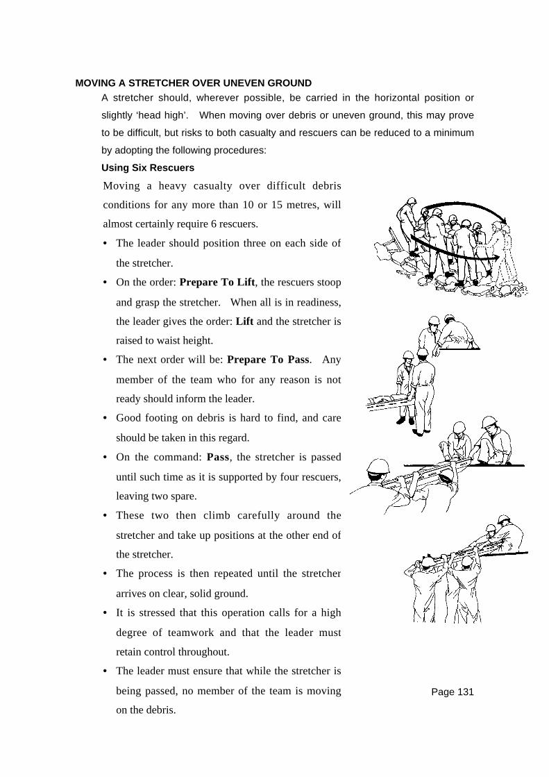
Page 131
MOVING A STRETCHER OVER UNEVEN GROUND
A stretcher should, wherever possible, be carried in the horizontal position or
slightly ‘head high’. When moving over debris or uneven ground, this may prove
to be difficult, but risks to both casualty and rescuers can be reduced to a minimum
by adopting the following procedures:
Using Six Rescuers
Moving a heavy casualty over difficult debris
conditions for any more than 10 or 15 metres, will
almost certainly require 6 rescuers.
• The leader should position three on each side of
the stretcher.
• On the order: Prepare To Lift, the rescuers stoop
and grasp the stretcher. When all is in readiness,
the leader gives the order: Lift and the stretcher is
raised to waist height.
• The next order will be: Prepare To Pass. Any
member of the team who for any reason is not
ready should inform the leader.
• Good footing on debris is hard to find, and care
should be taken in this regard.
• On the command: Pass, the stretcher is passed
until such time as it is supported by four rescuers,
leaving two spare.
• These two then climb carefully around the
stretcher and take up positions at the other end of
the stretcher.
• The process is then repeated until the stretcher
arrives on clear, solid ground.
• It is stressed that this operation calls for a high
degree of teamwork and that the leader must
retain control throughout.
• The leader must ensure that while the stretcher is
being passed, no member of the team is moving
on the debris.
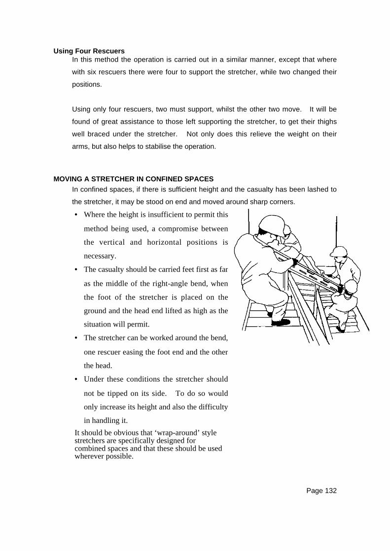
Page 132
Using Four RescuersIn this method the operation is carried out in a similar manner, except that where
with six rescuers there were four to support the stretcher, while two changed their
positions.
Using only four rescuers, two must support, whilst the other two move. It will be
found of great assistance to those left supporting the stretcher, to get their thighs
well braced under the stretcher. Not only does this relieve the weight on their
arms, but also helps to stabilise the operation.
MOVING A STRETCHER IN CONFINED SPACES
In confined spaces, if there is sufficient height and the casualty has been lashed to
the stretcher, it may be stood on end and moved around sharp corners.
• Where the height is insufficient to permit this
method being used, a compromise between
the vertical and horizontal positions is
necessary.
• The casualty should be carried feet first as far
as the middle of the right-angle bend, when
the foot of the stretcher is placed on the
ground and the head end lifted as high as the
situation will permit.
• The stretcher can be worked around the bend,
one rescuer easing the foot end and the other
the head.
• Under these conditions the stretcher should
not be tipped on its side. To do so would
only increase its height and also the difficulty
in handling it.
It should be obvious that ‘wrap-around’ stylestretchers are specifically designed forcombined spaces and that these should be usedwherever possible.

Page 133
PASSING A STRETCHER OVER A GAP
A large gap which has to be
negotiated by rescuers can be
overcome by laying an extension
ladder across it being mindful of
ladder load ratings, and, if possible,
placing a decking of boards over
the rungs.
Shorter gaps, such as in floors etc,
can be patched, using timber from
the site or possibly the short ladder.
Still smaller gaps can be traversed
in a similar way to that described
for moving over debris.


Page 135
CHAPTER TENIMPROVISED CASUALTY MOVEMENT
RESCUE TECHNIQUES USING NO EQUIPMENT
This subject is covered under two headings:
1. One Rescuer Handling Techniques
2. Two Rescuer Handling Techniques
It must be clearly understood that the following techniques are for use in an
emergency and that seriously injured casualties should, where possible, be
placed on a stretcher.
Conditions such as fire or imminent danger of building collapse, may however
dictate that removal from the scene is the first priority. In some cases this may
even take precedence over life sustaining first aid.
ONE RESCUER HANDLING TECHNIQUES
One Rescuer Human Crutch
WARNING NOTE:
All single rescuer techniques involve the risk of Injury to the rescuer.
For this method to work, the casualty must be conscious and
capable of giving the rescuer some assistance.
• Demonstration clearly indicates how the single rescuer
human crutch is effected.
• Note the position of the rescuer’s hands, one holding the
casualty’s wrist and the other taking a firm grip of the
clothes at the waist on the far side of the body.
• The injured side of the casualty should be closest to the
rescuer.

Page 136
Pick-A-Back
WARNING NOTE:
The rescuer effecting a pick-a-back or firefighter’s crawl carry runs a significant
risk of back injury and must take appropriate safety precautions.
Pack Strap CarryThis is used on the conscious casualty with no fractures of the extremities.
This is an effective method when conducted correctly.
• When the casualty has been loaded (must be
conscious), care should be taken to ensure they are
supported well up on the rescuer’s hips with the
body literally draped across the rescuer’s back.
• Turn your back to the
standing casualty.
• Bring their arms over your
shoulders to cross your
chest.
• Keep their arms straight as
possible, the armpits over
your shoulders.
• Hold casualty’s wrists, bend,
and pull the person onto
your back.
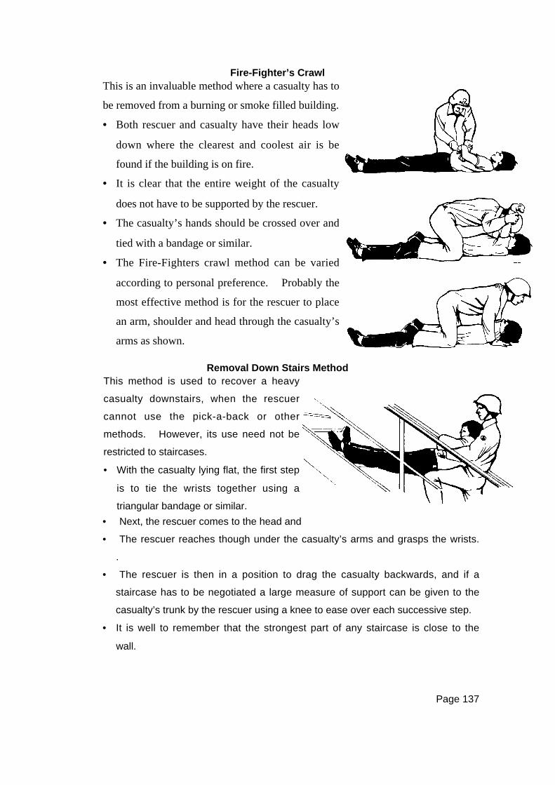
Page 137
Fire-Fighter’s Crawl
Removal Down Stairs Method
• Next, the rescuer comes to the head and lifts the casualty into sitting position.
• The rescuer reaches though under the casualty’s arms and grasps the wrists.
.
• The rescuer is then in a position to drag the casualty backwards, and if a
staircase has to be negotiated a large measure of support can be given to the
casualty’s trunk by the rescuer using a knee to ease over each successive step.
• It is well to remember that the strongest part of any staircase is close to the
wall.
This is an invaluable method where a casualty has to
be removed from a burning or smoke filled building.
• Both rescuer and casualty have their heads low
down where the clearest and coolest air is be
found if the building is on fire.
• It is clear that the entire weight of the casualty
does not have to be supported by the rescuer.
• The casualty’s hands should be crossed over and
tied with a bandage or similar.
• The Fire-Fighters crawl method can be varied
according to personal preference. Probably the
most effective method is for the rescuer to place
an arm, shoulder and head through the casualty’s
arms as shown.
This method is used to recover a heavy
casualty downstairs, when the rescuer
cannot use the pick-a-back or other
methods. However, its use need not be
restricted to staircases.
• With the casualty lying flat, the first step
is to tie the wrists together using a
triangular bandage or similar.
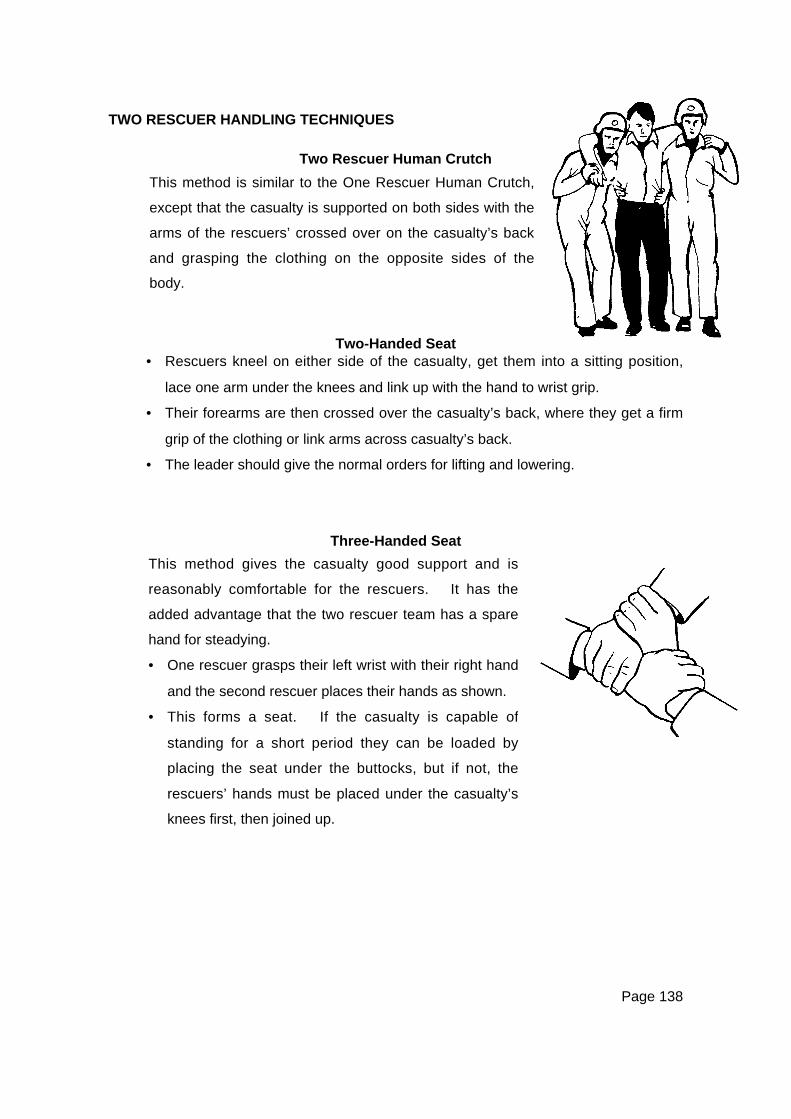
Page 138
TWO RESCUER HANDLING TECHNIQUES
Two Rescuer Human Crutch
Two-Handed Seat• Rescuers kneel on either side of the casualty, get them into a sitting position,
lace one arm under the knees and link up with the hand to wrist grip.
• Their forearms are then crossed over the casualty’s back, where they get a firm
grip of the clothing or link arms across casualty’s back.
• The leader should give the normal orders for lifting and lowering.
Three-Handed Seat
This method is similar to the One Rescuer Human Crutch,
except that the casualty is supported on both sides with the
arms of the rescuers’ crossed over on the casualty’s back
and grasping the clothing on the opposite sides of the
body.
This method gives the casualty good support and is
reasonably comfortable for the rescuers. It has the
added advantage that the two rescuer team has a spare
hand for steadying.
• One rescuer grasps their left wrist with their right hand
and the second rescuer places their hands as shown.
• This forms a seat. If the casualty is capable of
standing for a short period they can be loaded by
placing the seat under the buttocks, but if not, the
rescuers’ hands must be placed under the casualty’s
knees first, then joined up.

Page 139
Four-Handed Seat
The ‘Fore and Aft’ Method
This is a method where each rescuer grasps their left
wrist and the hands are joined up.
This provides a comfortable seat for the casualty and
places a minimum strain on the rescuers. However,
the casualty must be sufficiently conscious to hold on.
This is perhaps the most suitable way in which two
rescuers can handle an unconscious casualty.
• The casualty is prepared in the same way as for the
removal down stairs method ie: the wrists are tied
together.
• The first rescuer stoops at the rear of the casualty.
Reaching under the casualty’s arms, the first
rescuer grips the casualty’s wrists.
• The second rescuer stoops between the casualty’s
legs grasping them underneath the knees.
• The standard lift orders are given and the casualty
is lifted into the carrying position.
• Should the casualty have a leg injury, the effects of
this can be minimised by the front rescuer crossing
the casualty’s legs over, then carrying them to one
side.
• The advantage of this method is that the rescuer
supporting the casualty’s feet has a free hand with
which to open doors, clear debris, etc
It is again stressed that the foregoing one and two
rescuer techniques are generally confined to
emergencies where removal from the scene is the
first priority.
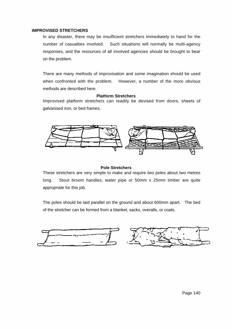
Page 140
IMPROVISED STRETCHERS
In any disaster, there may be insufficient stretchers immediately to hand for the
number of casualties involved. Such situations will normally be multi-agency
responses, and the resources of all involved agencies should be brought to bear
on the problem.
There are many methods of improvisation and some imagination should be used
when confronted with the problem. However, a number of the more obvious
methods are described here.
Platform StretchersImprovised platform stretchers can readily be devised from doors, sheets of
galvanised iron, or bed frames.
Pole StretchersThese stretchers are very simple to make and require two poles about two metres
long. Stout broom handles, water pipe or 50mm x 25mm timber are quite
appropriate for this job.
The poles should be laid parallel on the ground and about 600mm apart. The bed
of the stretcher can be formed from a blanket, sacks, overalls, or coats.
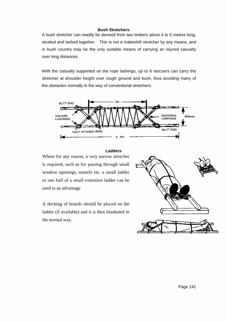
Page 141
Bush StretchersA bush stretcher can readily be devised from two timbers about 4 to 5 metres long,
strutted and lashed together. This is not a makeshift stretcher by any means, and
in bush country may be the only suitable means of carrying an injured casualty
over long distances.
With the casualty supported on the rope lashings, up to 8 rescuers can carry the
stretcher at shoulder height over rough ground and bush, thus avoiding many of
the obstacles normally in the way of conventional stretchers.
LaddersWhere for any reason, a very narrow stretcher
is required, such as for passing through small
window openings, tunnels etc. a small ladder
or one half of a small extension ladder can be
used to an advantage
A decking of boards should be placed on the
ladder (if available) and it is then blanketed in
the normal way.

Page 142
Chairs
A strong style kitchen chair can be used for
carries of casualties without serious injuries.

Page 143
CHAPTER ELEVENLIFTING & LOWERING TECHNIQUES
INTRODUCTION
In any disaster occurring in an urban environment, it can be assumed that large
numbers of casualties could be trapped in upper floors of buildings, in basements
or other depths, or many other difficult or inaccessible areas. In each case, the
method of rescue will be dictated by the circumstances and this chapter attempts
to provide some of the alternative methods of rescue often used. The simple
option of carrying a casualty up or down an inside stairway must never be
overlooked.
It must be stressed that the techniques included here are very basic. More
technical systems (requiring a higher level of training and expertise) can be used in
many circumstances.
Additionally, a number of improvised techniques are included in this chapter.
They are, in the main, those simple techniques which utilise materials found or
acquired on a disaster site, and which can readily be used to effect rescues.
MECHANICAL LOWERING METHODS
Basic vertical rescues can readily be carried out using equipment such as
Karabiners, descenders, and climbing tape. These techniques are best effected
using 11mm static rescue rope.
Page 144
STRETCHER OPERATIONS
The recovery of an injured person requires the bringing together of a wide range of
rescue skills with the use of rescue stretchers. Where any doubt exists as to
the casualty’s injuries, a stretcher must be used.
Depending on the injuries, terrain and conditions, a casualty can be recovered in a
horizontal or a vertical attitude. Wherever possible, it is recommended that
casualties be recovered in a horizontal attitude.
GUIDE AND SAFETY LINES
Two guide lines may be attached to stretchers during lowering operations to
prevent the stretcher from spinning, and in order to clear obstacles. These guide
lines are attached to the head and the foot of the stretcher for maximum control.
Rescuers controlling guide lines should wear gloves. Safety lines should be
attached to the stretcher as an added safety measure and belayed from above.
IMPROVISED SINGLE POINT LOWER
This improvised method should only be used when, because of fire or other
emergency combined with a lack of equipment, immediate evacuation of the
casualty is imperative.
The technique uses an 11mm rescue rope and a casualty support knot or a
stretcher, and consists of taking two round turns around a sound anchor point as a
belay.
The rope should be paid out hand-over-hand and the rescuers must wear gloves.
A more satisfactory single point lower technique can be achieved with a
mechanical descender.
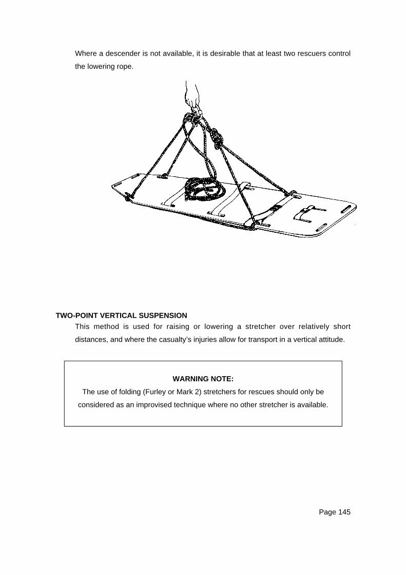
Page 145
Where a descender is not available, it is desirable that at least two rescuers control
the lowering rope.
TWO-POINT VERTICAL SUSPENSION
This method is used for raising or lowering a stretcher over relatively short
distances, and where the casualty’s injuries allow for transport in a vertical attitude.
WARNING NOTE:
The use of folding (Furley or Mark 2) stretchers for rescues should only be
considered as an improvised technique where no other stretcher is available.
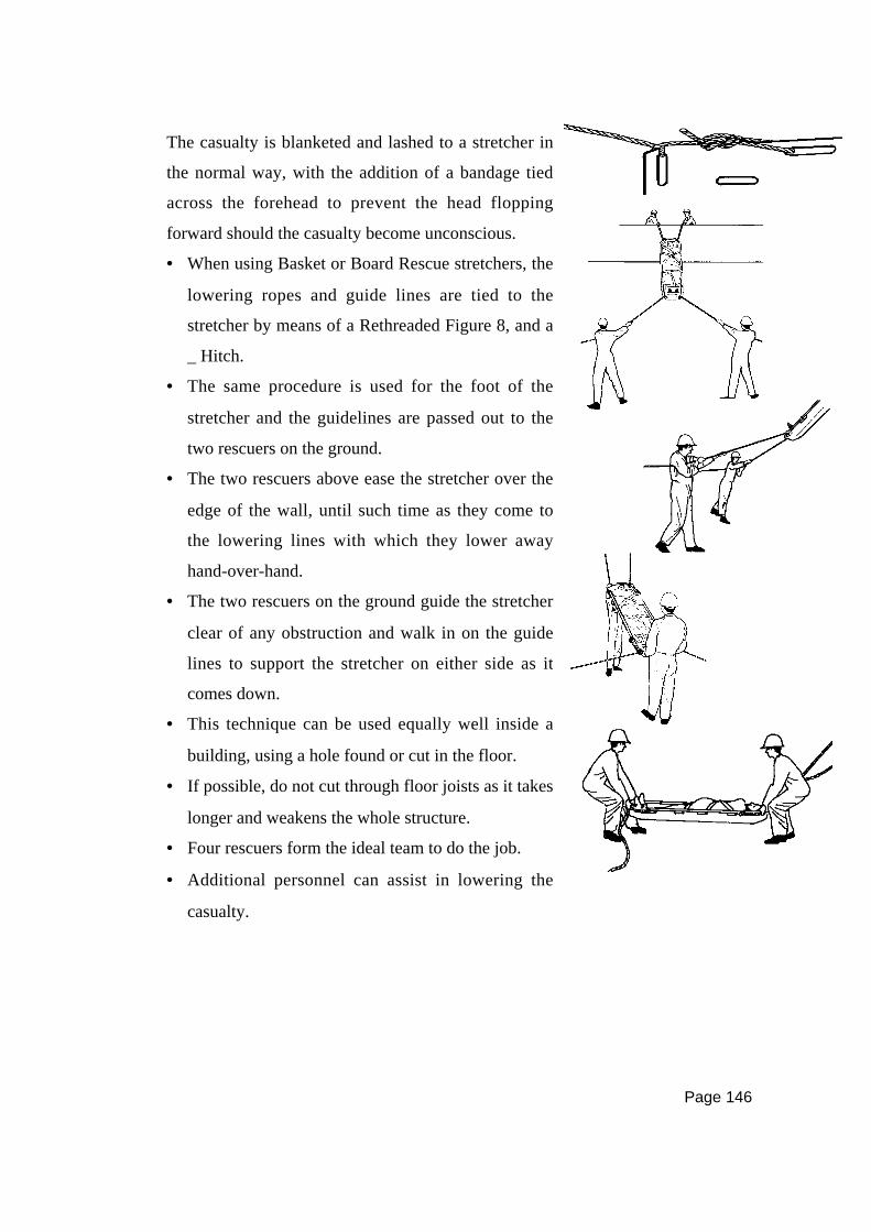
Page 146
The casualty is blanketed and lashed to a stretcher in
the normal way, with the addition of a bandage tied
across the forehead to prevent the head flopping
forward should the casualty become unconscious.
• When using Basket or Board Rescue stretchers, the
lowering ropes and guide lines are tied to the
stretcher by means of a Rethreaded Figure 8, and a
_ Hitch.
• The same procedure is used for the foot of the
stretcher and the guidelines are passed out to the
two rescuers on the ground.
• The two rescuers above ease the stretcher over the
edge of the wall, until such time as they come to
the lowering lines with which they lower away
hand-over-hand.
• The two rescuers on the ground guide the stretcher
clear of any obstruction and walk in on the guide
lines to support the stretcher on either side as it
comes down.
• This technique can be used equally well inside a
building, using a hole found or cut in the floor.
• If possible, do not cut through floor joists as it takes
longer and weakens the whole structure.
• Four rescuers form the ideal team to do the job.
• Additional personnel can assist in lowering the
casualty.
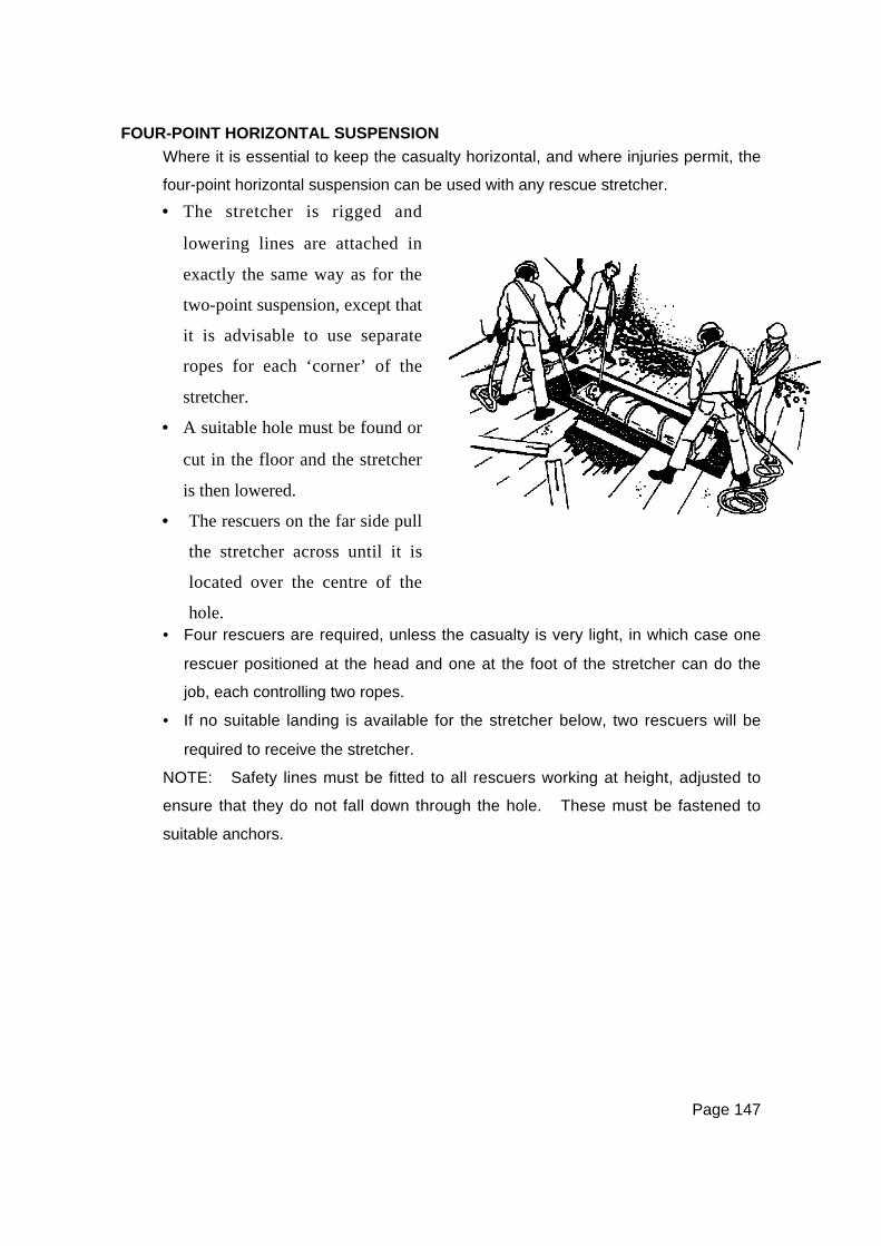
Page 147
FOUR-POINT HORIZONTAL SUSPENSION
Where it is essential to keep the casualty horizontal, and where injuries permit, the
four-point horizontal suspension can be used with any rescue stretcher.
• Four rescuers are required, unless the casualty is very light, in which case one
rescuer positioned at the head and one at the foot of the stretcher can do the
job, each controlling two ropes.
• If no suitable landing is available for the stretcher below, two rescuers will be
required to receive the stretcher.
NOTE: Safety lines must be fitted to all rescuers working at height, adjusted to
ensure that they do not fall down through the hole. These must be fastened to
suitable anchors.
• The stretcher is rigged and
lowering lines are attached in
exactly the same way as for the
two-point suspension, except that
it is advisable to use separate
ropes for each ‘corner’ of the
stretcher.
• A suitable hole must be found or
cut in the floor and the stretcher
is then lowered.
• The rescuers on the far side pull
the stretcher across until it is
located over the centre of the
hole.
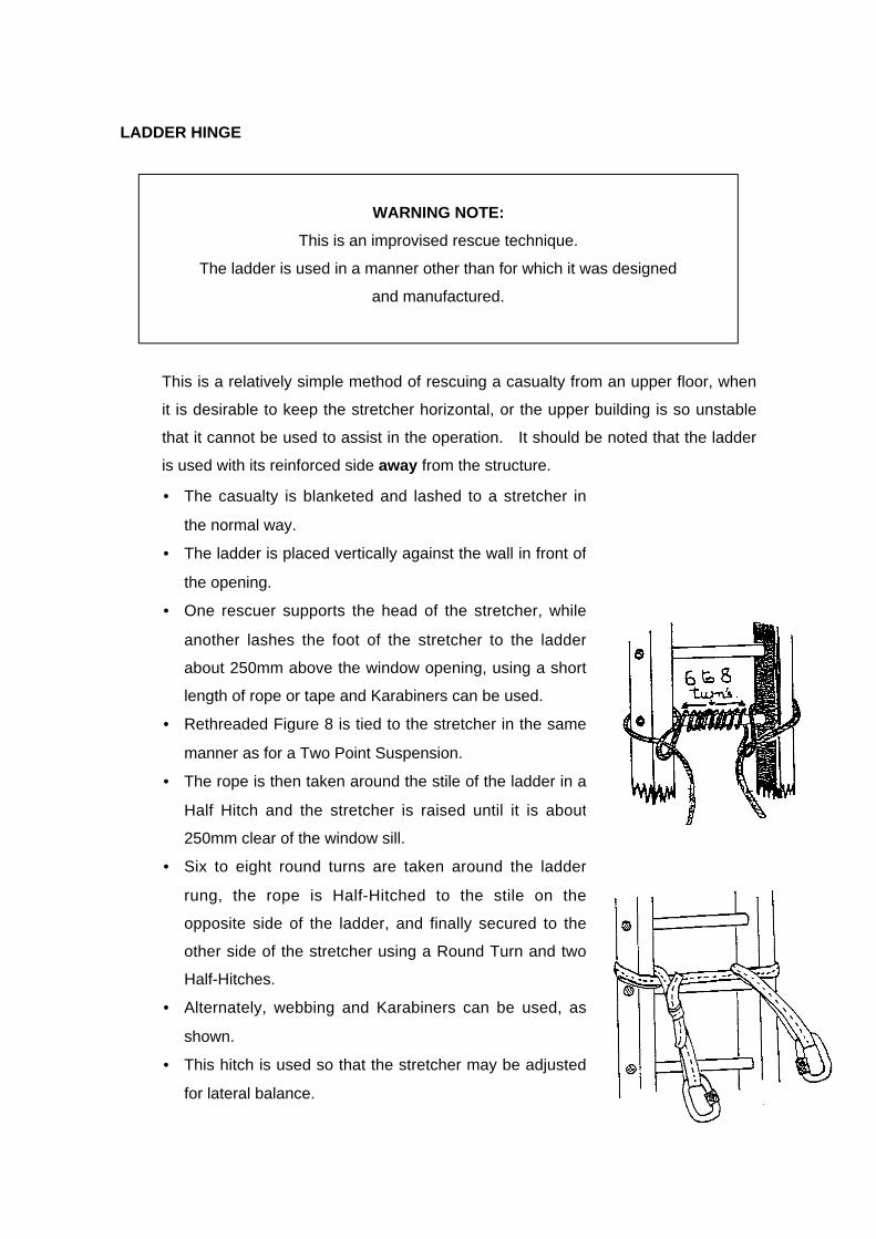
Page 148
LADDER HINGE
WARNING NOTE:
This is an improvised rescue technique.
The ladder is used in a manner other than for which it was designed
and manufactured.
This is a relatively simple method of rescuing a casualty from an upper floor, when
it is desirable to keep the stretcher horizontal, or the upper building is so unstable
that it cannot be used to assist in the operation. It should be noted that the ladder
is used with its reinforced side away from the structure.
• The casualty is blanketed and lashed to a stretcher in
the normal way.
• The ladder is placed vertically against the wall in front of
the opening.
• One rescuer supports the head of the stretcher, while
another lashes the foot of the stretcher to the ladder
about 250mm above the window opening, using a short
length of rope or tape and Karabiners can be used.
• Rethreaded Figure 8 is tied to the stretcher in the same
manner as for a Two Point Suspension.
• The rope is then taken around the stile of the ladder in a
Half Hitch and the stretcher is raised until it is about
250mm clear of the window sill.
• Six to eight round turns are taken around the ladder
rung, the rope is Half-Hitched to the stile on the
opposite side of the ladder, and finally secured to the
other side of the stretcher using a Round Turn and two
Half-Hitches.
• Alternately, webbing and Karabiners can be used, as
shown.
• This hitch is used so that the stretcher may be adjusted
for lateral balance.

Page 149
WARNING NOTE:
Where timber ladders are used for ladder hinge or ladder slide techniques,
the ladders must be reinforced with wire or fibreglass to support the stiles.
• Lowering lines are attached to the head end
of the stretcher, and when all is secure, the
word is passed to the leader who gives the
orders: Prepare To Lower and then: Lower.
• The stretcher is passed out of the window by
hand until the head end can be supported by
the lowering lines.
• Two rescuers remain close to where the
ladder has been footed, ensuring no side-
sway develops.
• One rescuer then walks backwards, hand-
over-hand with each rung, controlling the
speed of the whole operation.
• The stretcher should finally come to rest on
top of the ladder flat on the ground, from
where it can be quickly disconnected and
the casualty removed to safety.
NOTE: this method can also be readily used
to raise a casualty.

Page 150
LADDER SLIDE
•
• • .
• •
• •
• •
• •
• •
WARNING NOTE:
In the ladder slide technique, the ladder is used in a manner other than that for
which it was designed and manufactured. This is an improvised technique.
As the load on the centre of the span will be close to 150kg, the span must be
propped by one or two rescuers, or shored.
• The casualty is blanketed and
lashed to a stretcher, and two
lowering lines are secured to the
head end.
• The ladder is placed in position by
three rescuers at as steep an angle
as possible.
• One rescuer foots the ladder and
one or two act as human props.
• The rescuer climbs the ladder.
• The foot of the stretcher is passed
out onto the ladder.
• The stretcher is then moved down
the ladder until such time as the
head end passes clear of the
opening.
• The stretcher is slid down the
ladder, guided by the rescuer.
NOTE: This is a technique that can
also be used to raise a casualty to
safety.

Page 151
Some specific points to be observed with the Ladder Slide are:
• Where a timber ladder is used, it must be reinforced with wire or fibreglass stile
supports.
• Where a basket stretcher is used on an alloy ladder, there will be very little
friction, providing a rapid descent.
• The ladder must be set at as steep an angle possible for safety.
• Where ladders are extended to provide sufficient reach, the overlap should be
lashed with short rope or cord.
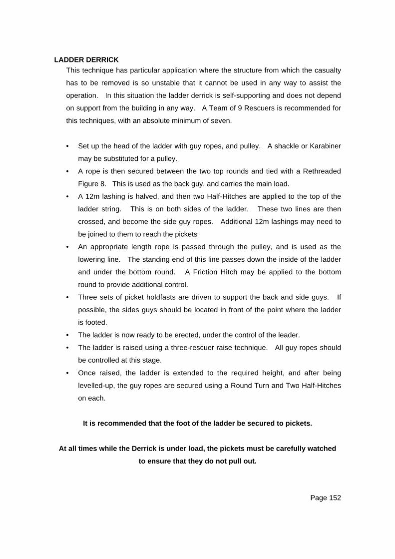
Page 152
LADDER DERRICK
This technique has particular application where the structure from which the casualty
has to be removed is so unstable that it cannot be used in any way to assist the
operation. In this situation the ladder derrick is self-supporting and does not depend
on support from the building in any way. A Team of 9 Rescuers is recommended for
this techniques, with an absolute minimum of seven.
• Set up the head of the ladder with guy ropes, and pulley. A shackle or Karabiner
may be substituted for a pulley.
• A rope is then secured between the two top rounds and tied with a Rethreaded
Figure 8. This is used as the back guy, and carries the main load.
• A 12m lashing is halved, and then two Half-Hitches are applied to the top of the
ladder string. This is on both sides of the ladder. These two lines are then
crossed, and become the side guy ropes. Additional 12m lashings may need to
be joined to them to reach the pickets
• An appropriate length rope is passed through the pulley, and is used as the
lowering line. The standing end of this line passes down the inside of the ladder
and under the bottom round. A Friction Hitch may be applied to the bottom
round to provide additional control.
• Three sets of picket holdfasts are driven to support the back and side guys. If
possible, the sides guys should be located in front of the point where the ladder
is footed.
• The ladder is now ready to be erected, under the control of the leader.
• The ladder is raised using a three-rescuer raise technique. All guy ropes should
be controlled at this stage.
• Once raised, the ladder is extended to the required height, and after being
levelled-up, the guy ropes are secured using a Round Turn and Two Half-Hitches
on each.
It is recommended that the foot of the ladder be secured to pickets.
At all times while the Derrick is under load, the pickets must be carefully watched
to ensure that they do not pull out.
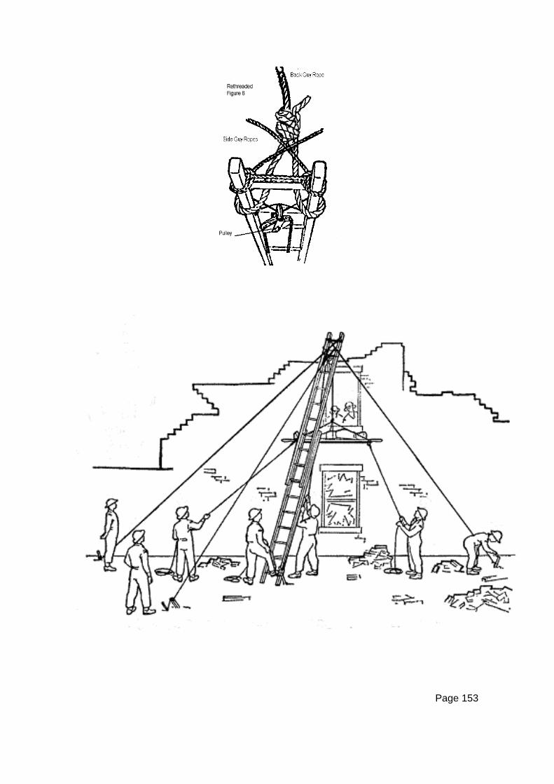
Page 153

Page 154
THE JIB• The jib consists of a pole projecting about one
metre horizontally out from a structure. A
snatch block or pulley, with a lowering line
passed through, is attached to the end. It is a
quick method of lowering stretchers in a
horizontal position.
• The material used for the jib must be strong
enough to allow the one metre projection to bear
all weight.
• Before pushing the jib pole out, the pulley must
be secured by tying a pulley to the pole.
• Alternatively, the pulley can be safely and
rapidly secured to the jib by means of tape
slings and a Karabiner.
• It is important that the lowering rope is passed
through the block or pulley, in such a way that
the running end goes directly to the lowering
party, and the standing part goes to the
stretcher. The rope should not cross.
• The pole must then be firmly lashed into
position, making sure that the pulley is in the
centre of the opening and not more than 1m out
from the wall in order to reduce leverage on the
jib.
• It is important that the pole be lashed as near as
possible to the point where it passes over the
wall as side strains will often be set up during
the lowering operation.
• The other end of the pole must be secured.
• Remember this end of the pole will tend to lift,
and this must be borne in mind when selecting
an anchorage.
Page 155
• It is not necessary that the pole should be at right angles to the wall or that it
should be in the horizontal plane, (eg: the inside end of the pole could be
anchored down to a floor joist, if it were solid).
• The casualty is blanketed and lashed in the usual way and secured to the rope
end in the appropriate manner.
• Two guide lines are attached to the stretcher and passed down to the rescuers
on the ground.
• A friction-lowering device is secured to an appropriate anchor point and the
lowering operation is controlled by a rescuer letting rope out slowly and
carefully through the device.
• When a lowering device is not available, at least two, preferably three,
rescuers will be required on the lowering rope.
• When all is ready, the weight is taken on the lowering rope and the two
rescuers up top ease the casualty out through the opening, feet first.
• As soon as possible the rescuers on the guide lines swing the stretcher around
parallel to the structure and lowering commences.
• Where necessary, the guide line rescuers can pull the stretcher out to a clear
landing space as it comes down.
• They should walk in on their lines so as to be ready to take hold of the
stretcher as it comes in reach.
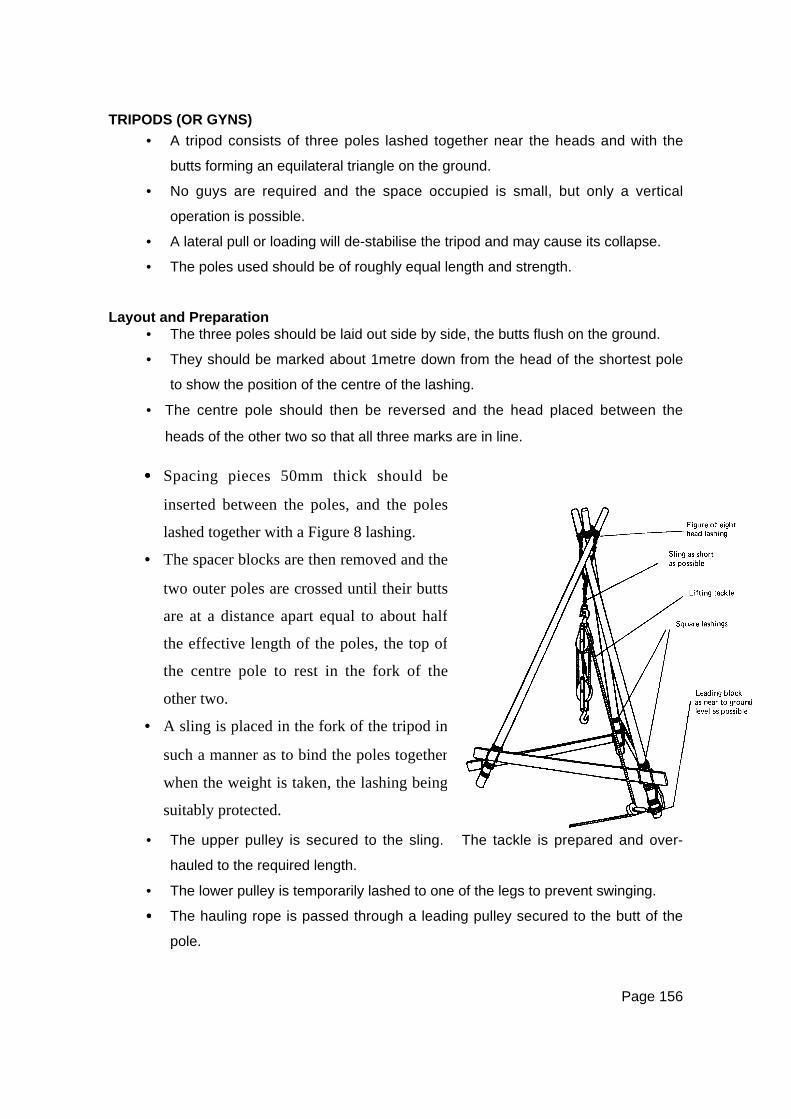
Page 156
TRIPODS (OR GYNS)
• A tripod consists of three poles lashed together near the heads and with the
butts forming an equilateral triangle on the ground.
• No guys are required and the space occupied is small, but only a vertical
operation is possible.
• A lateral pull or loading will de-stabilise the tripod and may cause its collapse.
• The poles used should be of roughly equal length and strength.
Layout and Preparation• The three poles should be laid out side by side, the butts flush on the ground.
• They should be marked about 1metre down from the head of the shortest pole
to show the position of the centre of the lashing.
• The centre pole should then be reversed and the head placed between the
heads of the other two so that all three marks are in line.
• The upper pulley is secured to the sling. The tackle is prepared and over-
hauled to the required length.
• The lower pulley is temporarily lashed to one of the legs to prevent swinging.
•••• The hauling rope is passed through a leading pulley secured to the butt of the
pole.
•••• Spacing pieces 50mm thick should be
inserted between the poles, and the poles
lashed together with a Figure 8 lashing.
• The spacer blocks are then removed and the
two outer poles are crossed until their butts
are at a distance apart equal to about half
the effective length of the poles, the top of
the centre pole to rest in the fork of the
other two.
• A sling is placed in the fork of the tripod in
such a manner as to bind the poles together
when the weight is taken, the lashing being
suitably protected.

Page 157
Raising• The head of the tripods should be lifted as far as possible by hand and the
centre pole brought in to form an equilateral triangle.
• The butts should be evenly spaced at a distance apart equal to about half the
height from the butt to the lashing. They must all be on the same level or the
weight will be distributed unevenly, and the tripod must be placed so that its
head is as near as possible over the centre of gravity of the load.
SecuringWhether a load is suspended or not, the tripod should not be left standing unless
the butts are secured against slipping.

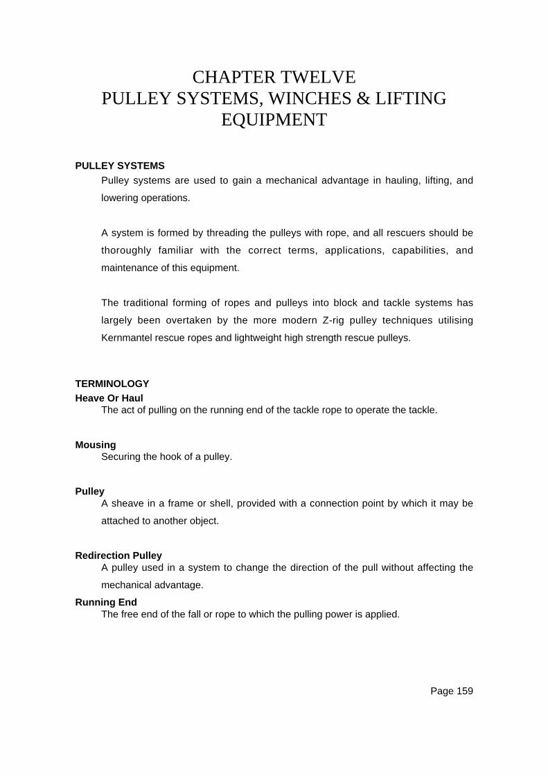
Page 159
CHAPTER TWELVEPULLEY SYSTEMS, WINCHES & LIFTING
EQUIPMENT
PULLEY SYSTEMS
Pulley systems are used to gain a mechanical advantage in hauling, lifting, and
lowering operations.
A system is formed by threading the pulleys with rope, and all rescuers should be
thoroughly familiar with the correct terms, applications, capabilities, and
maintenance of this equipment.
The traditional forming of ropes and pulleys into block and tackle systems has
largely been overtaken by the more modern Z-rig pulley techniques utilising
Kernmantel rescue ropes and lightweight high strength rescue pulleys.
TERMINOLOGY
Heave Or HaulThe act of pulling on the running end of the tackle rope to operate the tackle.
MousingSecuring the hook of a pulley.
PulleyA sheave in a frame or shell, provided with a connection point by which it may be
attached to another object.
Redirection PulleyA pulley used in a system to change the direction of the pull without affecting the
mechanical advantage.
Running EndThe free end of the fall or rope to which the pulling power is applied.
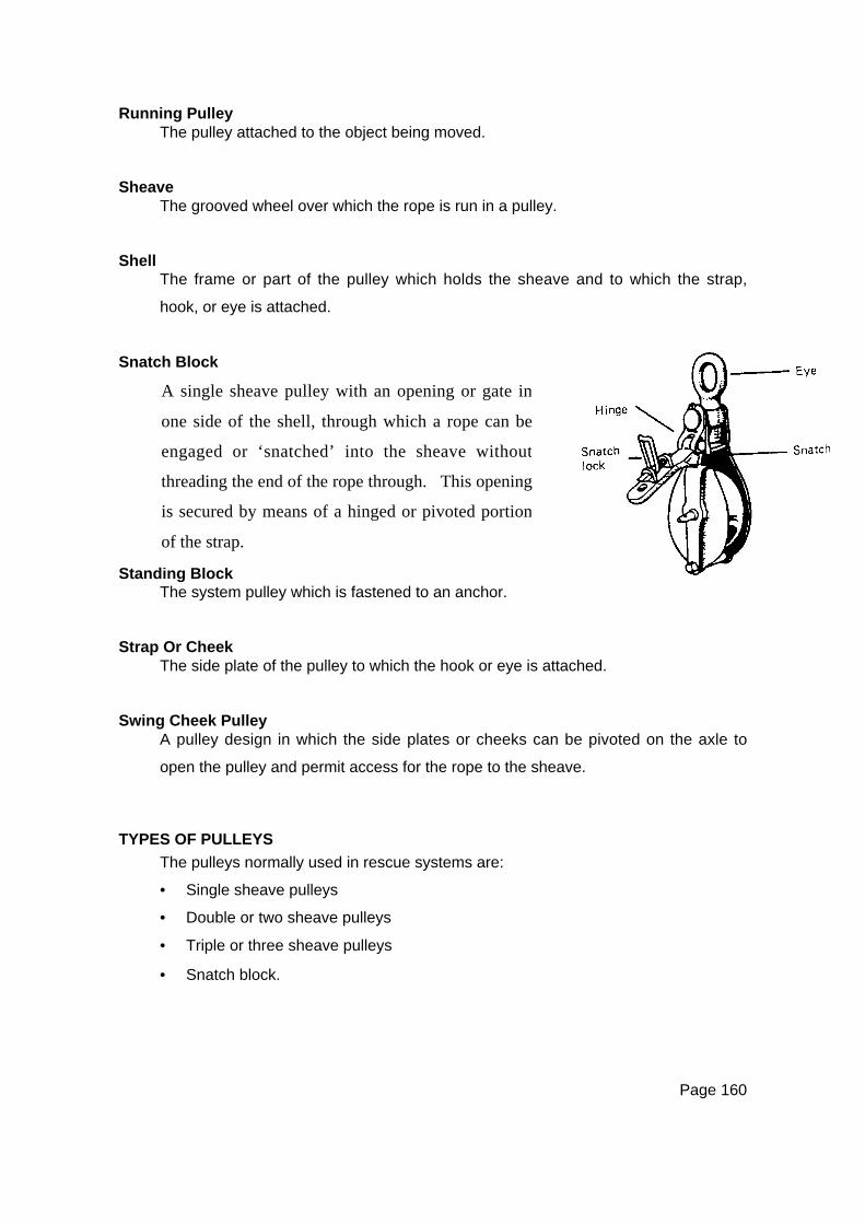
Page 160
Running PulleyThe pulley attached to the object being moved.
SheaveThe grooved wheel over which the rope is run in a pulley.
ShellThe frame or part of the pulley which holds the sheave and to which the strap,
hook, or eye is attached.
Snatch Block
Standing BlockThe system pulley which is fastened to an anchor.
Strap Or CheekThe side plate of the pulley to which the hook or eye is attached.
Swing Cheek PulleyA pulley design in which the side plates or cheeks can be pivoted on the axle to
open the pulley and permit access for the rope to the sheave.
TYPES OF PULLEYS
The pulleys normally used in rescue systems are:
• Single sheave pulleys
• Double or two sheave pulleys
• Triple or three sheave pulleys
• Snatch block.
A single sheave pulley with an opening or gate in
one side of the shell, through which a rope can be
engaged or ‘snatched’ into the sheave without
threading the end of the rope through. This opening
is secured by means of a hinged or pivoted portion
of the strap.
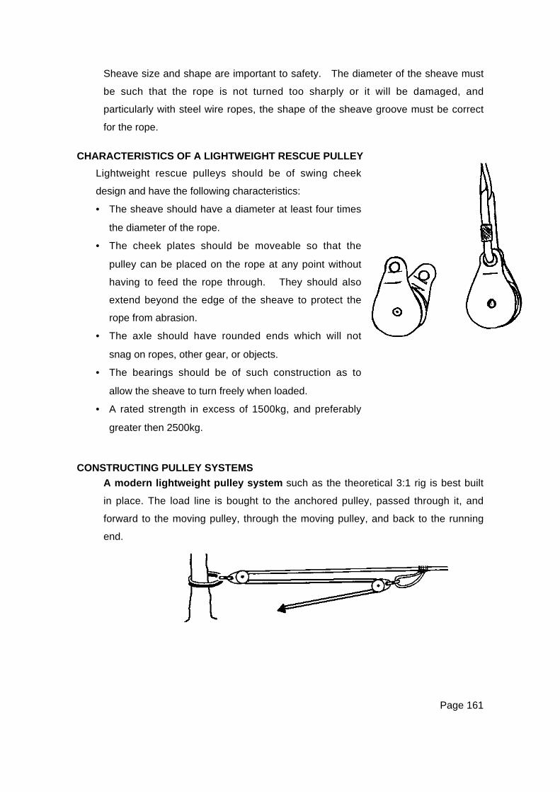
Page 161
Sheave size and shape are important to safety. The diameter of the sheave must
be such that the rope is not turned too sharply or it will be damaged, and
particularly with steel wire ropes, the shape of the sheave groove must be correct
for the rope.
CHARACTERISTICS OF A LIGHTWEIGHT RESCUE PULLEY
CONSTRUCTING PULLEY SYSTEMS
A modern lightweight pulley system such as the theoretical 3:1 rig is best built
in place. The load line is bought to the anchored pulley, passed through it, and
forward to the moving pulley, through the moving pulley, and back to the running
end.
Lightweight rescue pulleys should be of swing cheek
design and have the following characteristics:
• The sheave should have a diameter at least four times
the diameter of the rope.
• The cheek plates should be moveable so that the
pulley can be placed on the rope at any point without
having to feed the rope through. They should also
extend beyond the edge of the sheave to protect the
rope from abrasion.
• The axle should have rounded ends which will not
snag on ropes, other gear, or objects.
• The bearings should be of such construction as to
allow the sheave to turn freely when loaded.
• A rated strength in excess of 1500kg, and preferably
greater then 2500kg.

Page 162
TYPES OF PULLEY SYSTEMS
A lifting system is one in which the load is attached to the running (lowest) pulley,
and with the running end of the fall coming off the standing or upper pulley. When
calculating the capability of a lifting system, it must be realised that the only returns
between the pulleys assist in the lift, and that the running end does not help the lift
at all.
Power is applied to the running end, and in the opposite direction to the direction in
which the load is to be moved.
A hauling system is one in which the running end of the fall comes off the running
pulley (to which the load is attached), and the standing pulley is made fast to an
anchor of appropriate capability.
MECHANICAL ADVANTAGE
The Theoretical Mechanical Advantage (TMA) of a pulley system can be
calculated by counting the number of sheaves or the number of returns in the
system. For a system involving five sheaves, the TMA would be expressed as
being 5 to 1 (or 5:1).
The Actual Mechanical Advantage (AMA) is less than the theoretical one due to
the amount of friction caused by the ropes passing over the sheaves or contacting
each other in the returns. The actual efficiency of the pulleys in the system is also
taken into account.
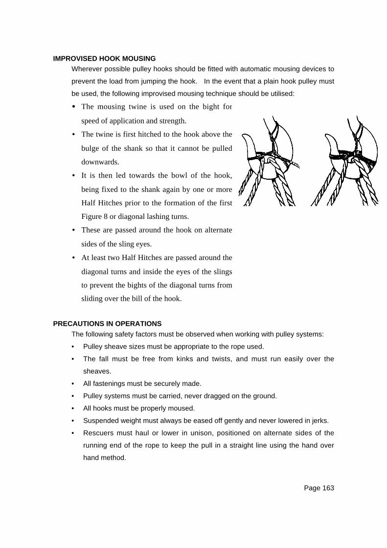
Page 163
IMPROVISED HOOK MOUSING
Wherever possible pulley hooks should be fitted with automatic mousing devices to
prevent the load from jumping the hook. In the event that a plain hook pulley must
be used, the following improvised mousing technique should be utilised:
PRECAUTIONS IN OPERATIONS
The following safety factors must be observed when working with pulley systems:
• Pulley sheave sizes must be appropriate to the rope used.
• The fall must be free from kinks and twists, and must run easily over the
sheaves.
• All fastenings must be securely made.
• Pulley systems must be carried, never dragged on the ground.
• All hooks must be properly moused.
• Suspended weight must always be eased off gently and never lowered in jerks.
• Rescuers must haul or lower in unison, positioned on alternate sides of the
running end of the rope to keep the pull in a straight line using the hand over
hand method.
•••• The mousing twine is used on the bight for
speed of application and strength.
• The twine is first hitched to the hook above the
bulge of the shank so that it cannot be pulled
downwards.
• It is then led towards the bowl of the hook,
being fixed to the shank again by one or more
Half Hitches prior to the formation of the first
Figure 8 or diagonal lashing turns.
• These are passed around the hook on alternate
sides of the sling eyes.
• At least two Half Hitches are passed around the
diagonal turns and inside the eyes of the slings
to prevent the bights of the diagonal turns from
sliding over the bill of the hook.
Page 164
• The returns near the pulleys should not be touched when they are moving, as
the rescuer’s hand may be trapped by the rope and drawn into the pulley.
• Not more than one tackle should ever be attached to either the load or the
anchor sling.
• Pulleys must be well maintained, carefully handled, and kept free or dirt and
grit, with all working parts sufficiently oiled to ensure free movement.
• Snatch blocks or single sheave blocks should be used on the running end of
the system as redirection pulleys wherever possible. This will change the
direction of haul to the horizontal, so that the rescue crew can work to best
advantage.
• When using snatch blocks, check safety pins are secured.
• All anchor points should be capable of supporting the total load involved.
LIFT / LOWER ROPE RESCUE DEVICES
A number of pre-rigged lift/lower rescue devices are readily available on the
commercial rescue market. These systems operate either as traditional pulley
rigs, or as friction drums or capstans. The devices are therefore easily
categorised as either pulley systems or drum systems.
Pulley systemsThese rigs are identical in design and operating principles to conventionally reeved
pulleys, with the most common configuration being a 4:1 TMA. Several models
are fitted with a rope brake cam in the shell of the anchored pulley, allowing for the
final rope return to be secured between hauls. This cam can be ‘tripped’ by an
accessory cord for lowering operations. Devices such as the Rescue Master
operate on the same principle but use a special inertial brake pulley.
Systems such as the ‘Haulsafe’ and the ‘Rescuemate’ utilise lightweight rescue
pulleys, and can readily be rigged with a length of rope that is appropriate to the
most common application within the agency’s area of operations. The entire kit
can then be stored and carried in a rope pack ready for deployment on all
lift/lower/haul tasks.

Page 165
Drum systemsDrum controlled systems such as the ‘Griptech’ and the ‘Rollgliss’ provide friction
for a controlled lower by means of the number of turns of rope formed around a
rolling drum. They can be used with or without a travelling pulley, and in general
provide a lower theoretical advantage for lifting/hauling than do the pulley systems.
OPERATIONAL USAGE – STANDARD PROCEDURES
• The device should be constructed with a length of rope which is sufficient for
normal applications in the area of response. This must take into account the
rope required to form the returns required for the specific device.
• When used for life rescue purposes, the device should be rigged with rope that
complies with New Zealand Standard AS4142.3:1993 - Static Rescue Lifelines.
• The devices must be used strictly in accordance with the manufacturer’s
guidelines.
• These systems can be anchored overhead for direct lift/lower operations, or
can be used for horizontal hauling. When used horizontally, additional care
must be taken to ensure that the device is clear of all contact.
• Safety brakes or cams must be active or fitted for all lift/haul operations.
• Standard procedures must be followed with respect to anchoring, crew
operations, commands, and the wearing of gloves.
WARNING NOTE:
For all mechanical winches, when SWR is under load, a heavy blanket or
similar should be placed across the rope so as to identify rope location
and in case of failure of rope will assist as a rope brake.
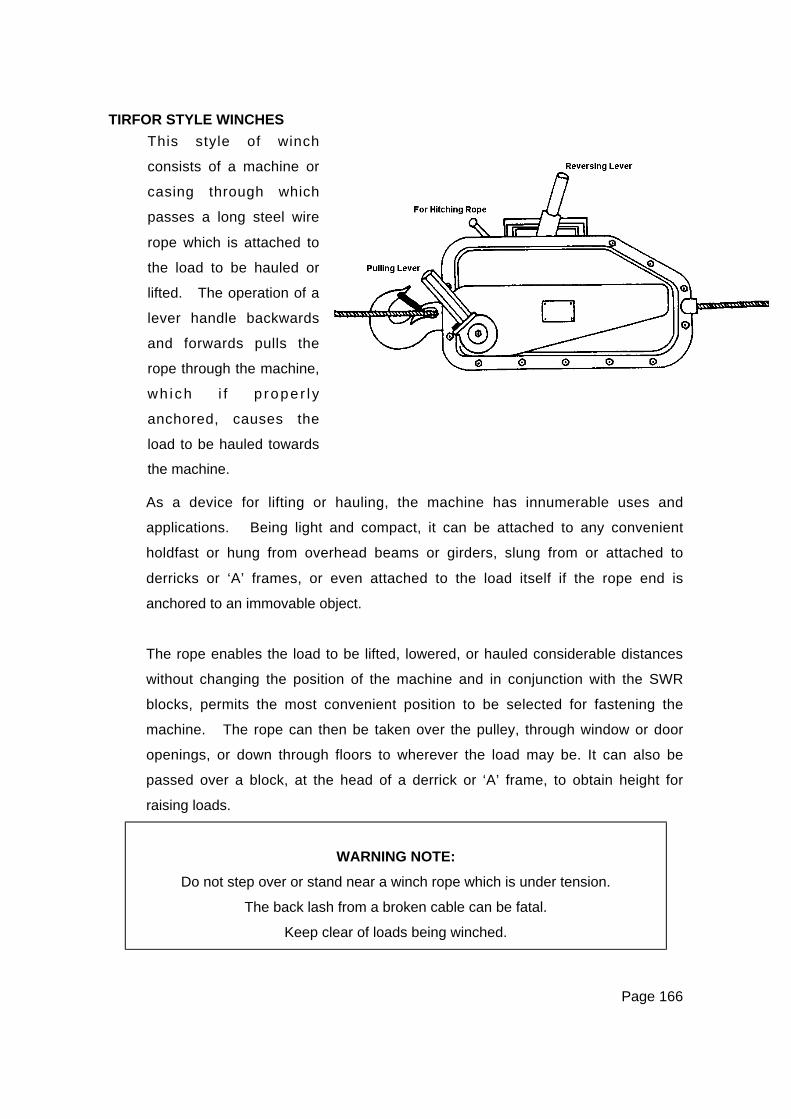
Page 166
TIRFOR STYLE WINCHES
As a device for lifting or hauling, the machine has innumerable uses and
applications. Being light and compact, it can be attached to any convenient
holdfast or hung from overhead beams or girders, slung from or attached to
derricks or ‘A’ frames, or even attached to the load itself if the rope end is
anchored to an immovable object.
The rope enables the load to be lifted, lowered, or hauled considerable distances
without changing the position of the machine and in conjunction with the SWR
blocks, permits the most convenient position to be selected for fastening the
machine. The rope can then be taken over the pulley, through window or door
openings, or down through floors to wherever the load may be. It can also be
passed over a block, at the head of a derrick or ‘A’ frame, to obtain height for
raising loads.
WARNING NOTE:
Do not step over or stand near a winch rope which is under tension.
The back lash from a broken cable can be fatal.
Keep clear of loads being winched.
This style of winch
consists of a machine or
casing through which
passes a long steel wire
rope which is attached to
the load to be hauled or
lifted. The operation of a
lever handle backwards
and forwards pulls the
rope through the machine,
wh ich i f p rope r l y
anchored, causes the
load to be hauled towards
the machine.

Page 167
The Tirfor Kit
The Tirfor winch kit consists of:
• A pulling and lifting winch unit complete with a swivel hook to enable it to be
secured.
• A detachable telescopic tubular steel handle for operating the unit.
• A length of flexible steel wire rope fitted with a hook at one end, the other end
being tapered and fused. (This rope is coiled on to a reel for convenience in
carriage).
The machine unit consists of a steel casing enclosing two pairs of automatic jaws
which grip the steel wire rope passing through the casing. These two pairs of
jaws are moved in opposite directions by means of linkages when the handle is
operated backwards and forwards. This alternating operation of the handle
results in a hauling or lifting movement in the rope.
WARNING NOTE:
Tirfor style winches must be operated and maintained in accordance with
manufacturers’ guidelines.
Precautions In Tirfor OperationsIf a single operator cannot move the load with the telescopic operating handle fully
extended; the load is too great for the machine and a steel wire rope block should
be used to increase the mechanical advantage.
• The operating handle must not be extended in any additional way.
• Always use slings and anchors of sufficient strength to withstand the load.
• Keep the wire rope wound on to the reel when not in use.
• Never allow any kinks in the rope to enter the machine as this causes internal
damage.
• Only use the wire rope supplied with the machine.
• Never anchor the machine by the tip of the hook; always use slings.
• Never apply tension to the running end of the rope.
• Never step or stand over a wire rope under tension, and remain clear of the
likely whip back areas, should the rope break.

Page 168
Safety Features Of TirforTirfor style winches have three safety features incorporated in their design:
• The clutch lever cannot be engaged whilst the machine is under load.
• If the strain on the lifting lever becomes too much for one rescuer, it can be
assumed that the machine has reached its safe working load.
• If the safe working limit of the machine is exceeded, there are three shear pins
in the shaft of the pulling lever. If rope and machine are in good condition,
these pins will fail before more serious damage can occur. Spare shear pins
should be carried in the hollow handle of the machine. No special tools are
required for replacement. The new pins are inserted, the load immediately
eased, and blocks added to the system for greater advantage.
THE RATCHET WINCH
This low cost, readily available, hand operated winch, is a useful tool for rescue,
but should not be viewed as a replacement for the Tirfor style winch.
The winch has a handle that cranks a drum via a pawl and ratchet system, thus
winding the wire onto the drum. Forward and reverse are achieved by a spring-
loaded control of the pawl. The wire rope length and the winch capacity will vary
from model to model and must be confirmed prior to use.
WARNING NOTE:
Some cheap ratchet winches are of very poor quality and capability.
A careful check should be made prior to use, and the
manufacturer’s guidelines must be followed closely.
Page 169
VEHICLE-MOUNTED POWER WINCHES
WARNING NOTE:
Never use vehicle mounted power winches to retrieve casualties.
The human body pulls apart often before the winch is overloaded.
Power winches are available in many types and variations, and each has its own
particular characteristics and attributes. In all cases, the manufacturers instructions
must be read carefully prior to use.
Precautions In Operations• Always be aware of the manufacturer’s specifications and safe working loads
and operate the winch within those parameters.
• Do not step over or stand near a winch rope while under tension, the back lash
from a broken cable can be fatal.
• Do not hook the winch rope back over itself, as this reduces the Safe Working
Load by up to 50 percent and damages the rope. Use an approved chain,
wire or synthetic fibre sling.
• Wear gloves at all times when handling the cable. Frayed cable can inflict
serious wounds.
• Do not handle the cable closer then 750mm from the drum when winching in.
A loose wire may snag the glove and draw the rescuer’s hand into the winch.
• Do not winch with less than five turns of cable around the drum.
• Do not use the winch for lifting casualties.
• Replace damaged wire ropes immediately.
• Most winches have a shear pin, which is designed to shear if the winch is
overloaded. The shear pin should only be replaced with a genuine
replacement pin.
• When winching, always pull in as straight a line as possible.
• Before applying a load to a new wire rope, it should be run out to the last five
wraps on the drum and spooled on to the winch under a load.
Page 170
• Always take out slack in the rope before applying full power to the winch.
Sudden jerks may exceed safe working loads.
• With a Power Take Off (PTO) winch, do not release the vehicle clutch rapidly, it
could shear the safety pin.
• Do not slip the vehicle clutch.
• Always wind the cable tightly. A good method for winding the cable, is to
extend it fully, attach it to a holdfast, and then pull the vehicle with the brakes
slightly applied. Wind the entire cable with this load.
The Power Take Off Winch (Mechanical Spool)The PTO mechanical winch is operated from the power take off, attached to the
gear box through a shaft, to the winch mounted on the front bumper bar of the
vehicle. Winch speed is controlled by varying the engine speed.
The Power Take Off Winch (Mechanical Capstan)This winch is mechanically the same to operate as the PTO spool winch, but
differs in the ‘spooling’ method. The capstan is a tapered, vertically positioned
drum around which a turn or two of the winch rope is taken. When the operator
applies pressure to the running end of the rope, the turning capstan causes the
rope to be recovered and thus winching occurs.
The Electrically Powered Spool WinchThe electric winch is one which the spool or drum is driven by an electric motor,
similar to a vehicle starter motor, through a gear train. The electric motor is
connected by heavy duty cables directly to the vehicle battery.
In most modern winches, a remote control switch to operate all winch functions is
supplied and is on a lead long enough to reach back to the drivers seat or to a safe
position clear of the cable and the load. A simple ‘push-pull’ clutch is fitted, so
that the drum can free spool to permit faster run out of the winch rope by hand to
the hook up point.
Although the winch will operate without the engine running, it is inadvisable to do
so unless absolutely necessary, due to the load the winch imposes on the battery.
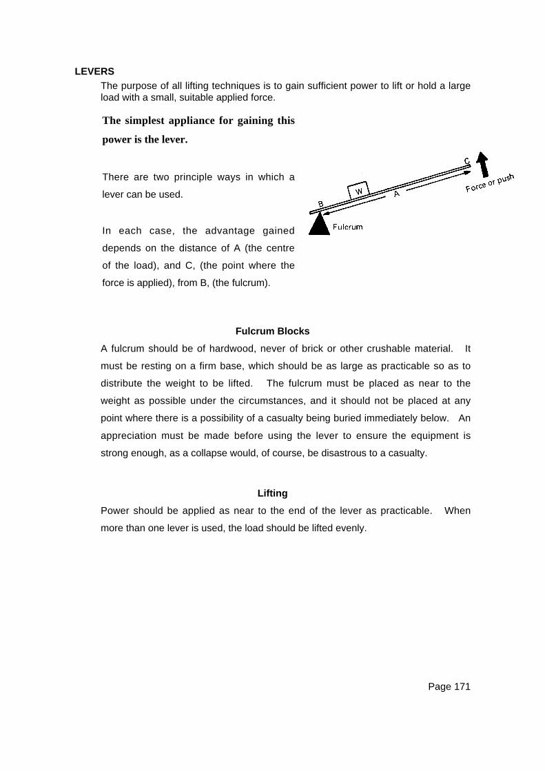
Page 171
LEVERS
The purpose of all lifting techniques is to gain sufficient power to lift or hold a largeload with a small, suitable applied force.
Fulcrum Blocks
A fulcrum should be of hardwood, never of brick or other crushable material. It
must be resting on a firm base, which should be as large as practicable so as to
distribute the weight to be lifted. The fulcrum must be placed as near to the
weight as possible under the circumstances, and it should not be placed at any
point where there is a possibility of a casualty being buried immediately below. An
appreciation must be made before using the lever to ensure the equipment is
strong enough, as a collapse would, of course, be disastrous to a casualty.
Lifting
Power should be applied as near to the end of the lever as practicable. When
more than one lever is used, the load should be lifted evenly.
The simplest appliance for gaining this
power is the lever.
There are two principle ways in which a
lever can be used.
In each case, the advantage gained
depends on the distance of A (the centre
of the load), and C, (the point where the
force is applied), from B, (the fulcrum).

Page 172
HYDRAULIC RESCUE EQUIPMENT
WARNING NOTE:
Hydraulic rescue equipment should only be used by appropriately trained and
qualified personnel.
Hydraulic equipment provides a tremendous mechanical advantage, which is
available in the form of a ram or spreader attachment which can be coupled to a
standard type of hydraulic pump. The power per weight of equipment can be
readily appreciated by the fact that a very basic pump and ram, weighing
approximately 9kg, can lift a load of 10 tonnes or more.
The advantage of using hydraulic equipment is that a comparatively small force
can be greatly increased. This is due to the fact that when a force is applied to a
fluid, it is transmitted equally and undiminished in all directions throughout the
fluid.
Hydraulic tools may be available to rescue teams in either hand-operated or
power or air-operated models.

Page 173
CHAPTER THIRTEENLIGHTING, POWER & CUTTING EQUIPMENT
GENERATORS
Numerous brands and types of generators are available commercially, but all are
basically similar in construction. They have a frame or case, and for safety
reasons are fitted with some form of Earth Leakage Circuit Breaker (ELCB) or
Residual Current Device (RCD) and a motor driven alternator to produce 240 volts
AC (Alternating Current). The ability of the alternator to deliver current is
measured by its power output rating in WATTS. This is a power rating that is also
often rated in KILOWATTS (kW), ie:
1 Kilowatt = 1000 Watts
ELCB’S and RCD’S
These are commonly used methods to describe the same thing. All portable
generators are built to minimise the possibility of electric shock.
For portable single-phase generators, an acceptable safe configuration is either:
•••• Option One
Floating (Isolated) Windings, without an ELCB/RCD.
With an isolated winding there is no loss of power in the event of a single fault
in the generator or in the load. Nor is there any indication of such fault.
Accordingly, it is ideal for lighting. A person touching ‘live parts’ will receive no
shock.
•••• Option Two
Polarised (Frame Connected) Windings, with an ELCB/RCD
With a frame connected winding plus RCD, a single fault on load-side
equipment will trip the RCD and cause loss of power. A person touching the
‘live parts’ will receive a minor shock, but will be protected by the RCD.

Page 174
Portable ELCBs/RCDs must be tested three (3) monthly as per AS3760. Other
devices must be tested twelve (12) monthly. If frequently used in harsh or severe
environments they should be tested at three (3) monthly intervals using the
procedures set out in AS3760.
POWER OUTPUT OF THE GENERATOR
Rescuers must know how to describe the amount of power that a particular
appliance will draw so as not to overload the generator.
• Lights and heating appliances are normally rated in Watts.
Therefore when using lights only, it is a simple matter to add the wattage of the
number of lights being used and subtract the figure from the generator capacity
to calculate the power still available.
Example: 3 banks of lights, each drawing 500 Watts are being used:
TOTAL WATTAGE IS 1500 WATTS
Therefore, if a generator was rated at 2500 WATTS or 2.5kW, it can be
seen that there is still 1000 Watts capacity left in the generator.
• Appliances using electric motors (eg: drills, chain saws, refrigerators, fans etc.)
often indicate the amount of current drawn from the generator, not the power.
This is usually found on a compliance plate on the appliance and is rated
Amps.
Example: An electric chain saw is rated at 5 Amps, the power it draws
from the generator is:
POWER (IN WATTS) = 240 VOLTS x 5 AMPS = 1200 WATTS
It can be seen that this particular chainsaw can be run from a 2500
Watt (2.5 kW) generator, but not from a 1000 Watt (1.0kW) generator.
• Rescue teams should calculate the power rating of each appliance likely to be
used and clearly mark this figure in Watts on the appliance to save time and
possible overload problems during an emergency.
Page 175
WARNING NOTE:
Motor starting current is approximately five times the rated full load current
of electric motors. When selecting generators for motor starting,
this factor should be considered to avoid overloads.
PRECAUTIONS IN OPERATIONS
Any combination of heat, petrol, and electricity, creates a potentially dangerous
situation.
The following list of precautions should be observed when operating any
generator.
• Do not place combustible material on or near the generator.
• Operate the generator on a stable, level surface to prevent fuel spillage,
excessive vibration, and oil starvation.
• During use, keep the generator at least 1 metre away from buildings and other
equipment.
• Avoid placing anything around the generator, or covering it up. Generators
are normally air-cooled and require a free flow of air to prevent overheating.
• Always stop the engine before refuelling.
• Be careful not to spill fuel on the generator. If fuel is spilt, wipe the machine
dry before starting the engine.
• Do not fill the fuel tank above the designated level.
• Do not smoke when refuelling, or expose the process to naked flame.
• Keep a suitable fire extinguisher nearby and upwind of the generator at all
times.
• Do not operate the generator in or near locations with poor ventilation such as
tunnels, under houses, inside tents, etc. Carbon Monoxide poisoning can
rapidly result from a build up of exhaust gases.

Page 176
ELECTRICAL SAFETY PRECAUTIONS
The electrical output of a generator is lethal. The following safety points should be
observed:
• Keep the generator dry. Exercise great care when operating in wet conditions.
• Never connect a generator to a household system.
• Coiled leads should be completely unwound before use.
• On-the-job surveillance of all electrical equipment, particularly leads, continues
to be the rule. Checks must be made when stowing or withdrawing equipment
from storage.
• Multiple outlets on floating generators are permitted if all equipment is double
insulated or ‘equipotential’ bound.
• All inspection and testing of electrical equipment shall be carried out by a
licensed electrician and in accordance with AS3760.
• All electrical equipment, including generators, leads, and fittings should be
tested by a licensed electrician within each twelve (12) month period. The
equipment mentioned must be tagged to indicate the date of inspection and
name of the person inspecting.
GENERATOR MAINTENANCE & OPERATIONAL CHECKS
Before operating any generator, read the manufacturers instruction and:
• Check sump oil level
• Ensure the correct fuel is used
• Use correct starting procedures.
• Generators must be properly maintained to the manufacturers specifications if
reliable and long service is to be expected.
• Generators should be run regularly under load.
Page 177
GENERATOR STORAGE
Many generators used by emergency services have periods where they may not
be used for some considerable time.
If this is the case:
• Store the generator with the piston in the compression stroke, thus closing both
the inlet and exhaust valves and also closing the breaker points.
− This procedure prevents corrosion of the combustion chamber, corrosion
of the contact points and prevents the valves from sticking open when
next the generator needs to be started. The compression stroke can be
found by pulling the starter cord or turning the starter pulley until it
becomes hard to turn (the piston is rising on the compression stroke),
then continuing to turn the pulley until just before the top of the piston
stroke.
• Drain the fuel from both the tank and the carburettor.
− Fuel left for long periods in the carburettor can cause a chemical reaction
that adversely affects carburettor components.
LIGHTING
Working at night can increase the dangers involved with rescue work due to
shadows, glare, and poor vision associated with artificial lighting systems.
Rescuers should experience night rescue situations in training and experiment with
various lighting arrangements, so as to eliminate as much as possible the three
hazards mentioned.

Page 178
Positioning LightingLittle in the way of guidance can be given when lighting the rescue scene because
all scenes vary greatly, but the following points are valid for most situations:
• Position lights as high as possible to illuminate the area required.
• If working at heights, do not shine lights from below to illuminate the situation.
For example, rescuers on roof tops can suffer a temporary and unsafe loss of
night vision by looking down into lights.
• If lights cannot be positioned above the scene, use hand lights or helmet
mounted lights only, controlled by the rescuers working at that height.
• A rescuer who is temporary blinded or suffering a loss of night vision for any
reason, should stay still and not move until night vision returns.
• A rescue scene is better illuminated with a soft, medium density light for
movement within the area, with the particular work scene being illuminated with
higher intensity lights such as spotlights.
• Position lights so that large shadows are minimised.
• Keep lighting leads away from any dangerous area where damage is likely to
occur.
HAND TOOLS FOR CUTTING
Bolt CuttersBolt cutters come in a variety of sizes and styles, but most are capable of cutting
through 8mm mild steel. This makes the tool valuable for debris clearance, in
reinforced concrete and the removal of padlocks and security grills in areas where
it is suspected casualties may be.
HacksawA hacksaw can be used in many situations. Always cut at right angles to the job.
Use a wedge to alleviate pressure on the blade. Cut as close as possible to a
supported section of the metal.
Cutting may be assisted by using a solution of 6:1 water/detergent to lubricate
hacksaw cuts.

Page 179
AxeAn axe can be used to cut timber or sheet metal. When used to cut sheet metal
as an improvised measure, the axe should be driven into the sheet so that the
blade penetrates to approximately half the depth of the cutting surface. The
handle should be pulled upwards so that the head is almost parallel with the metal.
A second rescuer should drive the axe head down with a sledgehammer while the
first guides it with the handle.
HandsawsOther types of handsaws such as the bow saw, general purpose saw, rip saw, etc.
all have a part to play in the rescue tool kit and should not be neglected.
Remember to train with hand tools, because in a disaster they may be all that you
will have.

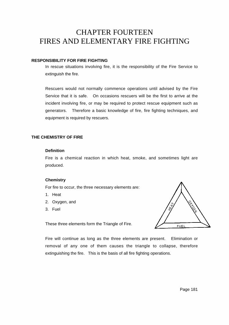
Page 181
CHAPTER FOURTEENFIRES AND ELEMENTARY FIRE FIGHTING
RESPONSIBILITY FOR FIRE FIGHTING
In rescue situations involving fire, it is the responsibility of the Fire Service to
extinguish the fire.
Rescuers would not normally commence operations until advised by the Fire
Service that it is safe. On occasions rescuers will be the first to arrive at the
incident involving fire, or may be required to protect rescue equipment such as
generators. Therefore a basic knowledge of fire, fire fighting techniques, and
equipment is required by rescuers.
THE CHEMISTRY OF FIRE
Definition
Fire is a chemical reaction in which heat, smoke, and sometimes light are
produced.
Chemistry
For fire to occur, the three necessary elements are:
1. Heat
2. Oxygen, and
3. Fuel
These three elements form the Triangle of Fire.
Fire will continue as long as the three elements are present. Elimination or
removal of any one of them causes the triangle to collapse, therefore
extinguishing the fire. This is the basis of all fire fighting operations.
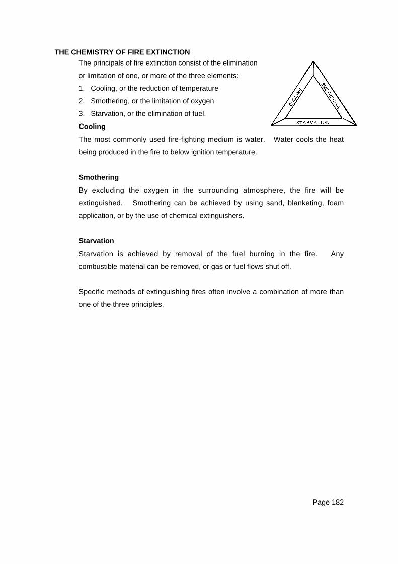
Page 182
THE CHEMISTRY OF FIRE EXTINCTION
The principals of fire extinction consist of the elimination
or limitation of one, or more of the three elements:
1. Cooling, or the reduction of temperature
2. Smothering, or the limitation of oxygen
3. Starvation, or the elimination of fuel.
Cooling
The most commonly used fire-fighting medium is water. Water cools the heat
being produced in the fire to below ignition temperature.
Smothering
By excluding the oxygen in the surrounding atmosphere, the fire will be
extinguished. Smothering can be achieved by using sand, blanketing, foam
application, or by the use of chemical extinguishers.
Starvation
Starvation is achieved by removal of the fuel burning in the fire. Any
combustible material can be removed, or gas or fuel flows shut off.
Specific methods of extinguishing fires often involve a combination of more than
one of the three principles.

Page 183
CLASSES OF FIRE
Fires are classified according to the nature of the fuel involved. There are
currently six classes of fire as shown in the following table.
CLASS
ACombustible solids
Carbonaceous solids such aswood, paper, plastics, andclothing.
CLASS
BFlammable and combustibleliquids
Petroleum based liquids suchas petrol, oil, alcohol, andthinners.
CLASS
CFlammable gases
Gases in either vapour orliquefied form such aspropane, butane, methane, oracetylene
CLASS
DCombustible metalsFires of this type require specialextinguishers and expert advice
Metals such as magnesium,sodium, potassium, oraluminium powder.
CLASS
EElectrical Fires
Fires that involve energised or‘live’ electrical equipment orservices.
CLASS
FCooking oils and fats
Grease, fats and cooking oils.

Page 184
STANDARD FIRE EXTINGUISHER OPERATING PROCEDURES:
The following procedure is in line with current practice:
P Pull the pin
T Test the extinguisher is going to operate
A Aim at the base of the fire
S Squeeze the operating trigger
S Sweep the flames off the fuel.
FIRE HOSE REELS
Hose reels can be operated by a single rescuer. The basic procedure is:
• Ensure that the nozzle or jet is in the closed position.
• Turn on the main valve (most reels have a device that only charges the
nozzle when the valve is opened).
• Pull the hose off the drum, towards the fire.
• Open the nozzle or valve, and direct the stream of water at the base of the
fire.
ACTION TO BE TAKEN BY A PERSON DISCOVERING A FIRE
The following standard procedure is recommended:
• Assess the situation
• Raise the alarm
• Evacuate the immediate area
• Call the Fire Service
• Attack the fire – only if safe to do so
• Always work in pairs.
Page 185
WORKING AND MOVING IN SMOKE
Working in smoke is extremely dangerous and should be avoided. Rescuers
working under these conditions should wear self-contained breathing apparatus,
and should be protected by safety lines.
Under emergency conditions, rescuers may have to enter a smoke-affected area
to conduct a rescue or to leave the site. On these occasions, rescuers must
keep close to the floor, work in pairs, and be monitored by rescuers outside in the
clear air.
Refer also to Chapter 2, Moving in an unknown environment, for further
information that may be relevant.

Page 187
CHAPTER FIFTEENRESCUE TEAM EQUIPMENT
PERSONAL EQUIPMENTAll rescue personnel must be equipped with the following protective equipment as aminimum requirement:Personal Equipment
• Overalls With some form of identification showing the
organisation to which the person belongs.
• Safety Helmet Complete with chinstrap. Colour to be uniform within
team.
• Footwear Leather safety boots or shoes with non-slip soles.
• Debris Gloves Palm to be leather.
• Goggles To give good all round protection from dust and debris.
• Personal Safety Line Minimum length of 4 metres of at least 8 mm line.
• Torch (or Helmet Lamp) With spare batteries & bulbs.
• First Aid Personal First Aid kit (1 x Triangular & 2 x Field
Dressings, 4 pr x Surgical Gloves).
Helmet Markings
• Team Leader 2 red bands (reflective) around the helmet.
• Deputy Team Leader 1 red band (reflective) around the helmet.
• All Team Members An option would be to have 1 reflective band around the
helmet, as well as the Civil Defence logo and the
member’s name.
Optional Identification, etc.
• Reflective Jerkin An option to other means of identification.
• Other badges, logos, etc. Should be kept to a minimum to avoid confusion for
team members, and to assist recognition from all angles.
The team member is responsible for all equipment issued to them, and shouldreport damage immediately.
Page 188
RESCUE TEAM EQUIPMENT LIST (SUGGESTED ONLY)
The following list is a guide to the minimum equipment necessary to equip a 6 – 8person basic rescue team (extra to personal equipment listed previously):
Item Quantity
Personal Equipment
Boots Safety Boots or shoes 8
First Aid / Medical Surgical Gloves (4 pr per person)
1 x Triangular Bandage,
2 x Field Dressing
32
8
16
Gloves Leather Debris 8
Goggles Eye protection 10
Helmet Safety Helmet (suitably marked) 8
Lines Personal (4+m x 8+mm) 8
Mask Dust, moulded type 8
Overalls Heavy Duty Cotton 8
Torch (or Head Lamp) 1 each as applicable 8
Team Equipment
Blankets Wool / wool mix, hemmed, standard single size 8
Ladder Extension (wooden, 4m x 7m) 1
Lines Lashing (12mm x 12m) 8
Masks Dust, moulded type 10
Pickets 5
Stretcher Board Rescue
Basket type (high impact plastic)
Furley / NATO / Field type
2
1
2
Tools Crowbar
Wood saw (general purpose)
Hacksaw with spare blades
Sledgehammer (3.5 kg)
1
1
1
1
Torch (or Head Lamp) Spares 2

Page 189
APPENDIX
Index of Photographs on CD-ROM and Website
Chapter 1 nil
Chapter 2 Stair Climb
Chapter 3 nil
Chapter 4 Bight of a RopeChair Knot (5)Vertical Lift Knot (7)
Chapter 5 Alpine Butterfly (8)Double Figure 8 on a Bight (4)Double Fisherman’s Knot (8)Figure 8 Joining Knot (4)Figure 8 on a Bight (2)Friction Hitch (4)Kernmantel Rope (2)Prusik Knot (5)Rethreaded Figure 8 (5)Round Turn & 2 Half-Hitches (4)Tape Knot (5)Thumb Knot
Chapter 6 Thumb KnotTimber Hitch (5)
Chapter 7 3,2,1 PicketAutolock DescendersKarabinersFriction DevicesMallionPulleysRacksStretcher Karabiner
Chapter 8 Ladder Angle CheckLadder ClimbingLadder Leg LockLadder Picketing

Page 190
Ladder Raise 3 Rescuers (3)Ladder Step OffLadder Tie Off – Top
Chapter 9 4 Person Lift (3)Blanket Lift (2)Board Lashing (2)Board Lowering LineClothing LiftFour Person LiftNATO stretchers (5)
Chapter 10 1 Person Walk2 Person Assisted Walk3 Handed Seat4 Handed SeatFiremans CrawlFore and Aft Carry (2)Improvised Ladder StretcherImprovised Chair LiftPack Strap-Piggy BackPack Strap CarryStair Carry
Chapter 11 2 Point Lower4 Point Lower (5)Basket Stretcher (4)Ladder Hinge (5)Ladder Slide (3)
Chapter 12 nil
Chapter 13 nil
Chapter 14 nil
Chapter 15 nil