Embed Size (px)
Citation preview
GENERAL REFERENCE MANUAL
Preface
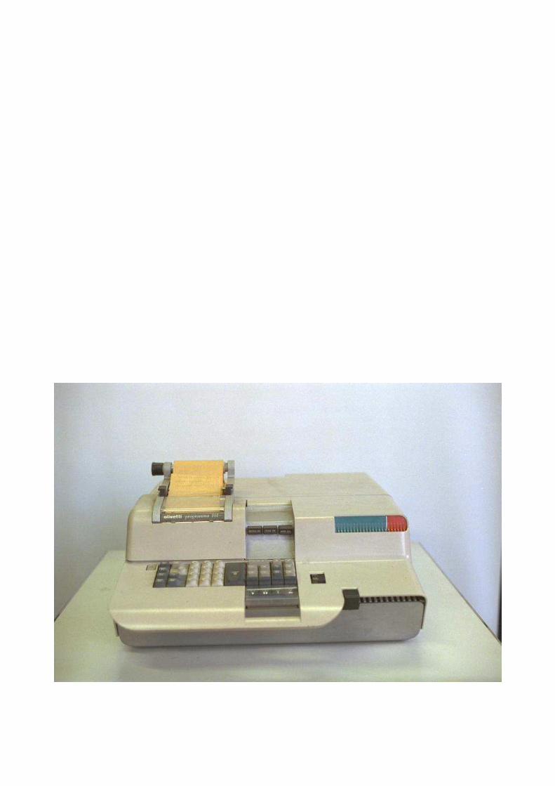
Programma 101 is a completely self-contained desk-
top machine capable of operating in manual mode as a
high speed electronic printing calculator, in program
mode as an automatic computer with the ability to
follow stored instructions, or in a combination of the
two modes.
This manual discusses the operation and capabilities of
Programma 101 in all of its modes. It is divided into a
description of the computer, an explanation of its
program language, and a brief presentation of the
procedures and techniques for its programming and
use.
Contents Page Computer Components . . . . . . . . . . . 6 Memory . . . . . . . . . . . . . . . . 7 Keyboard . . . . . . . . . . . . . . . 11 Decimal Wheel . . . . . . . . . . . . . . 15 Split Register . . . . . . . . . . . . . 16 General Operations . . . . . . . . . . . 17 Start-S . . . . . . . . . . . . . . . 17 Clear . . . . . . . . . . . . . . . . 17 Print . . . . . . . . . . . . . . . . 17 Vertical Spacing . . . . . . . . . . . 17 Data Transfer Operations. . . . . . . . . 18 To A. . . . . . . . . . . . . . . . . . . 18 From M . . . . . . . . . . . . . . . . . 19 Exchange. . . . . . . . . . . . . . . . . 20 D-R Exchange. . . . . . . . . . . . . . . 21 Decimal Part To M . . . . . . . . . . . . 22 Arithmetic Operations . . . . . . . . . . 23 Addition. . . . . . . . . . . . . . . . . 24 Subtraction . . . . . . . . . . . . . . . 25 Multiplication. . . . . . . . . . . . . . 26 Division . . . . . . . . . . . . . . . . 27 Square Root . . . . . . . . . . . . . . . 28 Absolute Value . . . . . . . . . . . . . 29 Jump Operations . . . . . . . . . . . . . 30 Unconditional Jumps . . . . . . . . . . . 31 Conditional Jumps . . . . . . . . . . . . 32 Constants . . . . . . . . . . . . . . . . 34 Constants in Registers . . . . . . . . . 34 Constants as Instructions . . . . . . . . 35 Computer Utilization . . . . . . . . . . 36 To Record a Program . . . . . . . . . . . 36 Read/Record D and E . . . . . . . . . . . 37 To Print a Program. . . . . . . . . . . . 37 To Use a Program . . . . . . . . . . . . 38 Automatic Internal Checks . . . . . . . . 38 Manual Mode . . . . . . . . . . . . . . . 39 Computer Exercise . . . . . . . . . . . . 40 Changing The Ribbon . . . . . . . . . . . 42 Insertion of Paper Roll . . . . . . . . . 43 Programming Techiques . . . . . . . . . . 44 Rounding Techniques . . . . . . . . . . . 45 Instruction-Data Storage. . . . . . . . . 47 Counters. . . . . . . . . . . . . . . . . 50 Packing a Register. . . . . . . . . . . . 51 The Domino Technique. . . . . . . . . . . 52 Chaining. . . . . . . . . . . . . . . . . 53 Sample Program. . . . . . . . . . . . 54-60
Computer Components
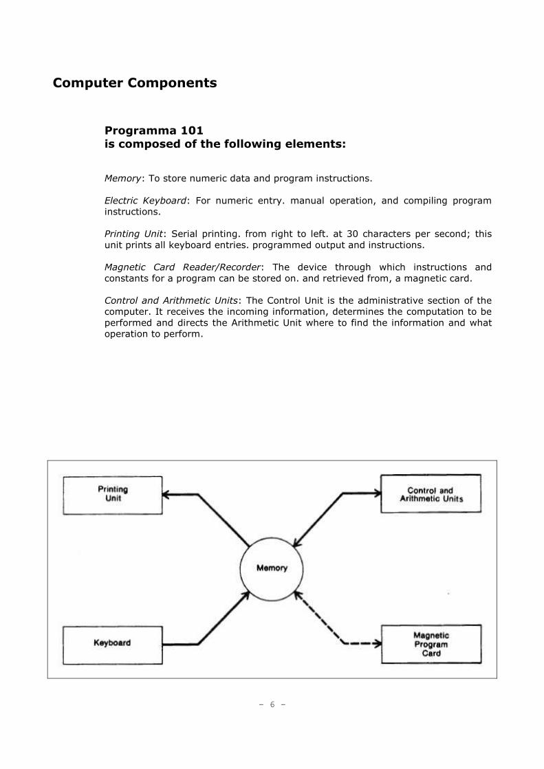
Programma 101
is composed of the following elements:
Memory: To store numeric data and program instructions.
Electric Keyboard: For numeric entry. manual operation, and compiling program
instructions.
Printing Unit: Serial printing. from right to left. at 30 characters per second; this
unit prints all keyboard entries. programmed output and instructions.
Magnetic Card Reader/Recorder: The device through which instructions and
constants for a program can be stored on. and retrieved from, a magnetic card.
Control and Arithmetic Units: The Control Unit is the administrative section of the
computer. It receives the incoming information, determines the computation to be
performed and directs the Arithmetic Unit where to find the information and what
operation to perform.
- 6 -
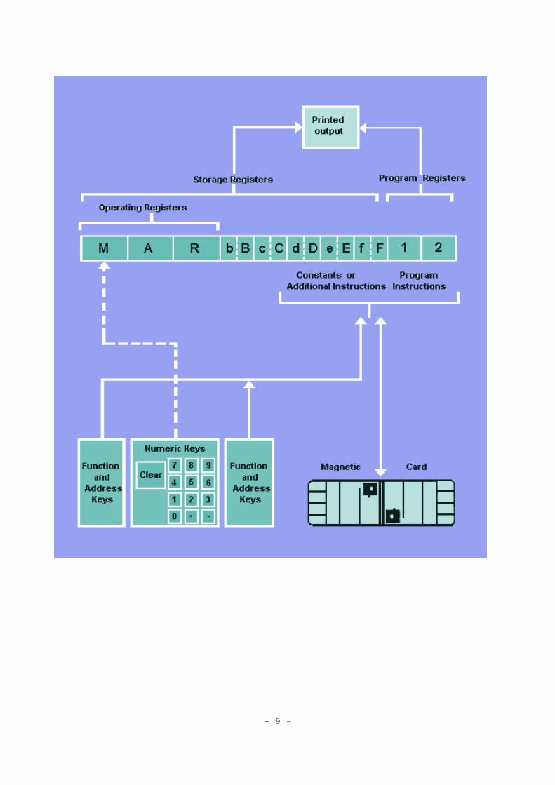
Memory
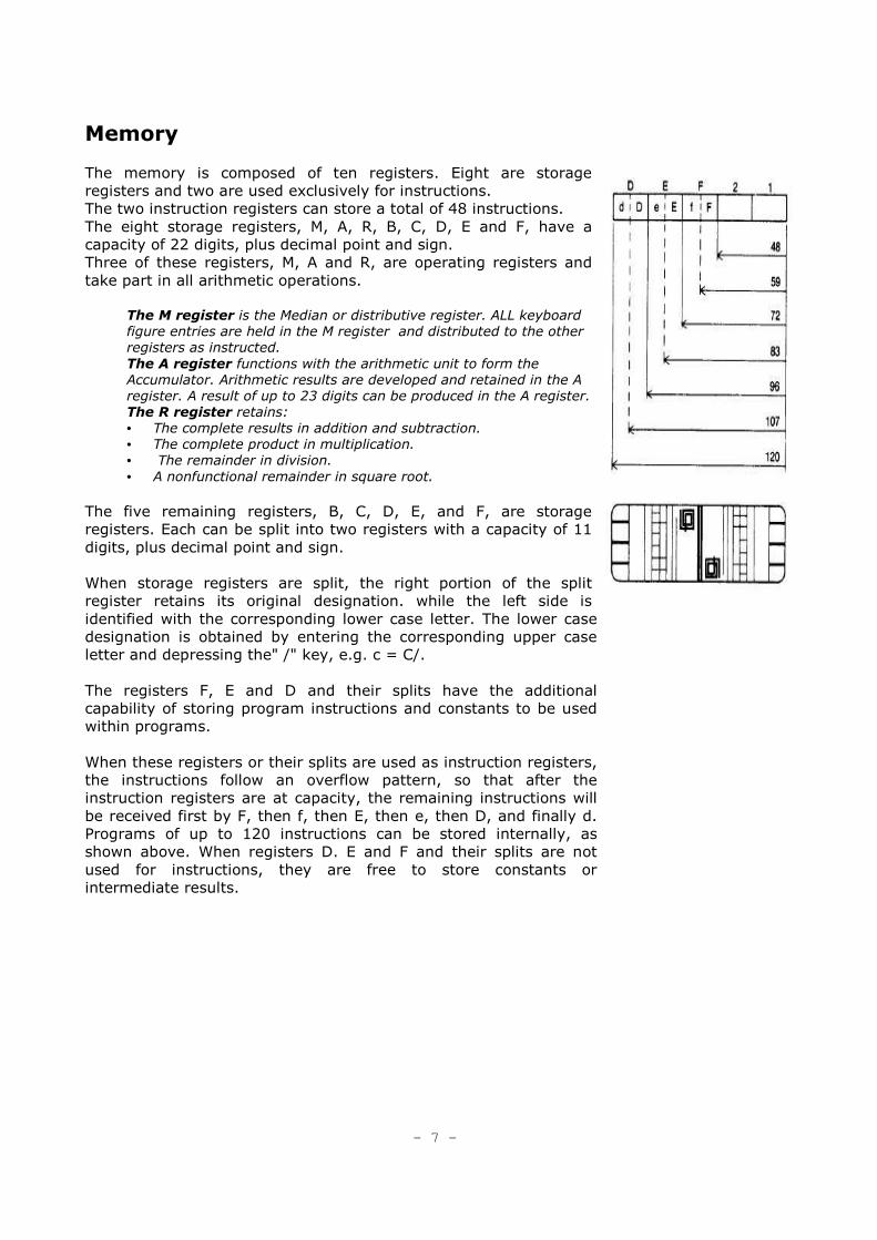
The memory is composed of ten registers. Eight are storage
registers and two are used exclusively for instructions.
The two instruction registers can store a total of 48 instructions.
The eight storage registers, M, A, R, B, C, D, E and F, have a
capacity of 22 digits, plus decimal point and sign.
Three of these registers, M, A and R, are operating registers and
take part in all arithmetic operations.
The M register is the Median or distributive register. ALL keyboard
figure entries are held in the M register and distributed to the other
registers as instructed.
The A register functions with the arithmetic unit to form the
Accumulator. Arithmetic results are developed and retained in the A
register. A result of up to 23 digits can be produced in the A register.
The R register retains:
• The complete results in addition and subtraction.
• The complete product in multiplication.
• The remainder in division.
• A nonfunctional remainder in square root.
The five remaining registers, B, C, D, E, and F, are storage
registers. Each can be split into two registers with a capacity of 11
digits, plus decimal point and sign.
When storage registers are split, the right portion of the split
register retains its original designation. while the left side is
identified with the corresponding lower case letter. The lower case
designation is obtained by entering the corresponding upper case
letter and depressing the" /" key, e.g. c = C/.
The registers F, E and D and their splits have the additional
capability of storing program instructions and constants to be used
within programs.
When these registers or their splits are used as instruction registers,
the instructions follow an overflow pattern, so that after the
instruction registers are at capacity, the remaining instructions will
be received first by F, then f, then E, then e, then D, and finally d.
Programs of up to 120 instructions can be stored internally, as
shown above. When registers D. E and F and their splits are not
used for instructions, they are free to store constants or
intermediate results.
- 7 -
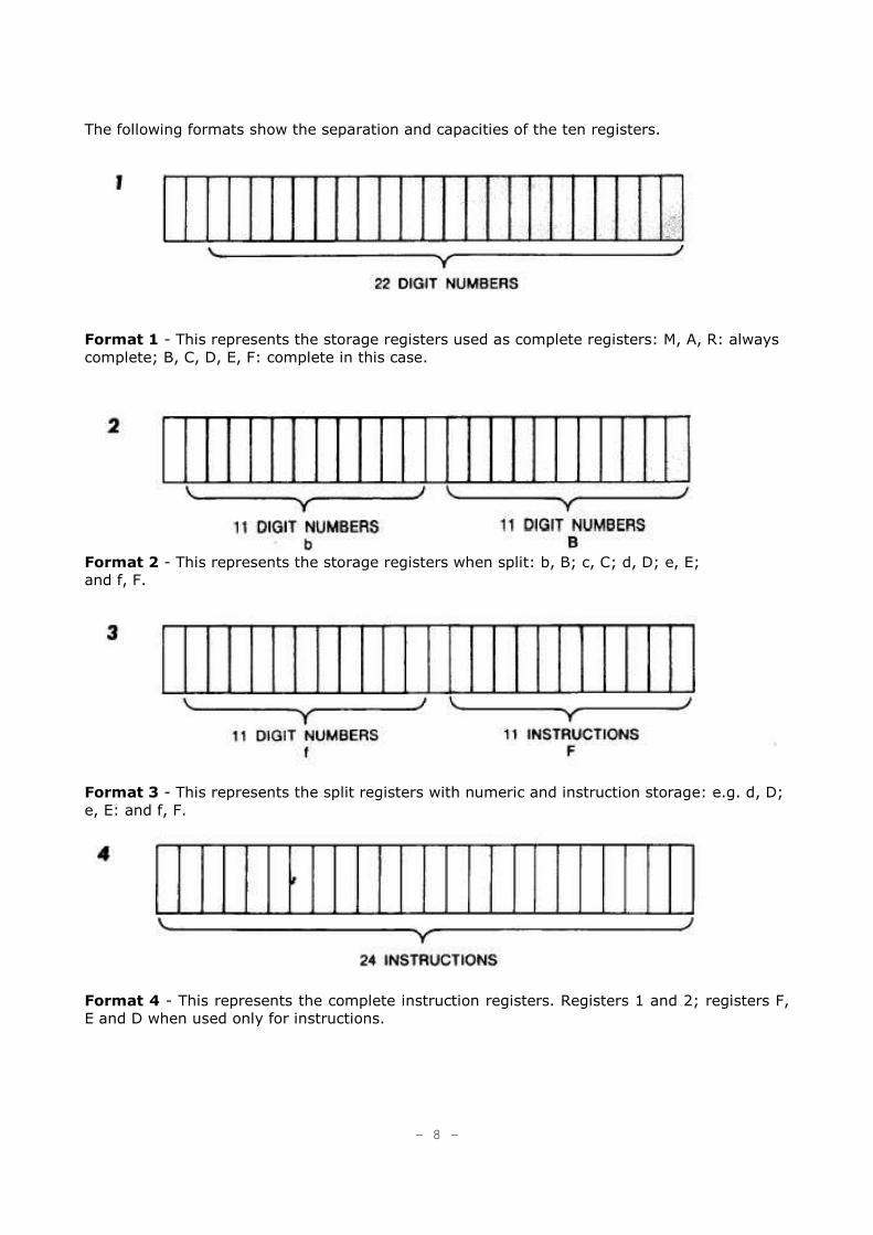
The following formats show the separation and capacities of the ten registers.
Format 1 - This represents the storage registers used as complete registers: M, A, R: always
complete; B, C, D, E, F: complete in this case.
Format 2 - This represents the storage registers when split: b, B; c, C; d, D; e, E;
and f, F.
Format 3 - This represents the split registers with numeric and instruction storage: e.g. d, D;
e, E: and f, F.
Format 4 - This represents the complete instruction registers. Registers 1 and 2; registers F,
E and D when used only for instructions.
- 8 -
- 9 –
-10-
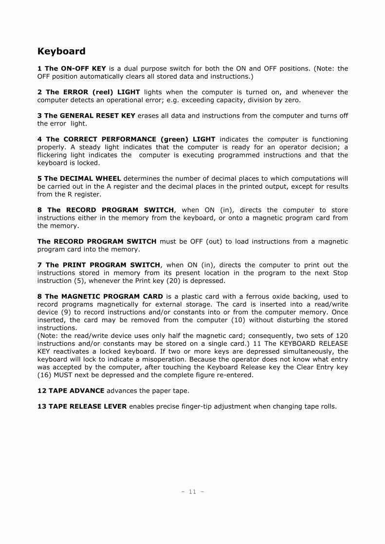
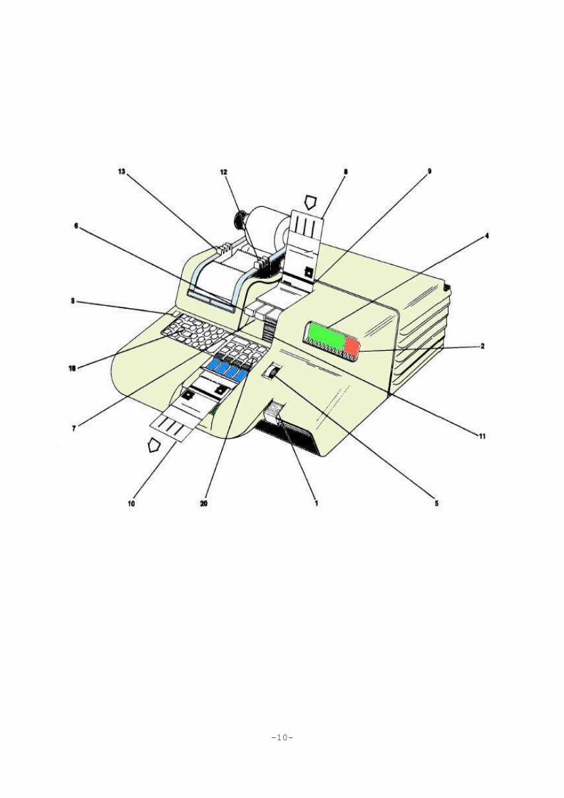
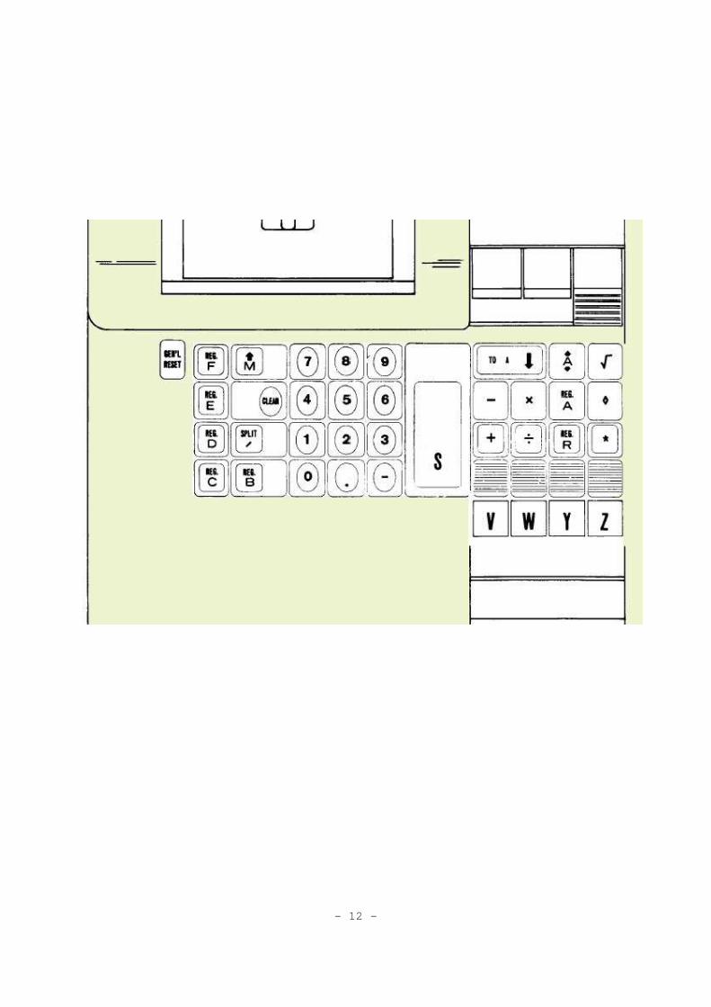
Keyboard
1 The ON-OFF KEY is a dual purpose switch for both the ON and OFF positions. (Note: the
OFF position automatically clears all stored data and instructions.)
2 The ERROR (reel) LIGHT lights when the computer is turned on, and whenever the
computer detects an operational error; e.g. exceeding capacity, division by zero.
3 The GENERAL RESET KEY erases all data and instructions from the computer and turns off
the error light.
4 The CORRECT PERFORMANCE (green) LIGHT indicates the computer is functioning
properly. A steady light indicates that the computer is ready for an operator decision; a
flickering light indicates the computer is executing programmed instructions and that the
keyboard is locked.
5 The DECIMAL WHEEL determines the number of decimal places to which computations will
be carried out in the A register and the decimal places in the printed output, except for results
from the R register.
8 The RECORD PROGRAM SWITCH, when ON (in), directs the computer to store
instructions either in the memory from the keyboard, or onto a magnetic program card from
the memory.
The RECORD PROGRAM SWITCH must be OFF (out) to load instructions from a magnetic
program card into the memory.
7 The PRINT PROGRAM SWITCH, when ON (in), directs the computer to print out the
instructions stored in memory from its present location in the program to the next Stop
instruction (5), whenever the Print key (20) is depressed.
8 The MAGNETIC PROGRAM CARD is a plastic card with a ferrous oxide backing, used to
record programs magnetically for external storage. The card is inserted into a read/write
device (9) to record instructions and/or constants into or from the computer memory. Once
inserted, the card may be removed from the computer (10) without disturbing the stored
instructions.
(Note: the read/write device uses only half the magnetic card; consequently, two sets of 120
instructions and/or constants may be stored on a single card.) 11 The KEYBOARD RELEASE
KEY reactivates a locked keyboard. If two or more keys are depressed simultaneously, the
keyboard will lock to indicate a misoperation. Because the operator does not know what entry
was accepted by the computer, after touching the Keyboard Release key the Clear Entry key
(16) MUST next be depressed and the complete figure re-entered.
12 TAPE ADVANCE advances the paper tape.
13 TAPE RELEASE LEVER enables precise finger-tip adjustment when changing tape rolls.
- 11 -
- 12 -
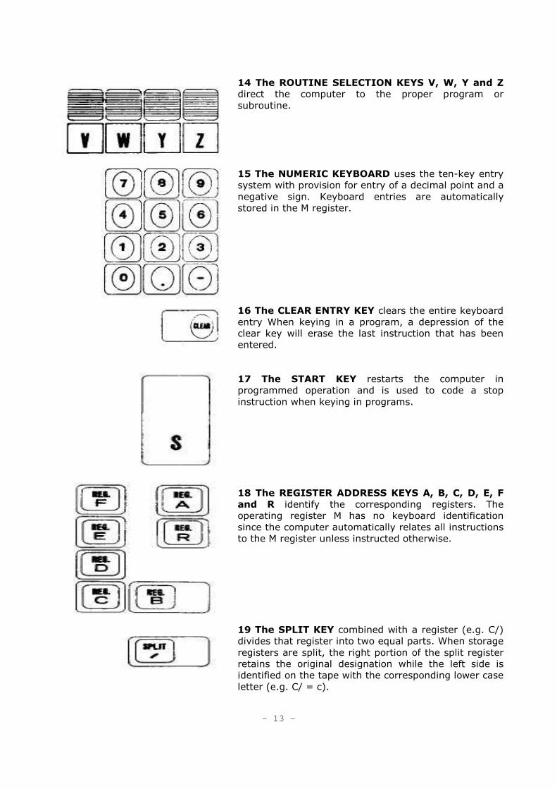
14 The ROUTINE SELECTION KEYS V, W, Y and Z
direct the computer to the proper program or
subroutine.
15 The NUMERIC KEYBOARD uses the ten-key entry
system with provision for entry of a decimal point and a
negative sign. Keyboard entries are automatically
stored in the M register.
16 The CLEAR ENTRY KEY clears the entire keyboard
entry When keying in a program, a depression of the
clear key will erase the last instruction that has been
entered.
17 The START KEY restarts the computer in
programmed operation and is used to code a stop
instruction when keying in programs.
18 The REGISTER ADDRESS KEYS A, B, C, D, E, F
and R identify the corresponding registers. The
operating register M has no keyboard identification
since the computer automatically relates all instructions
to the M register unless instructed otherwise.
19 The SPLIT KEY combined with a register (e.g. C/)
divides that register into two equal parts. When storage
registers are split, the right portion of the split register
retains the original designation while the left side is
identified on the tape with the corresponding lower case
letter (e.g. C/ = c).
- 13 -
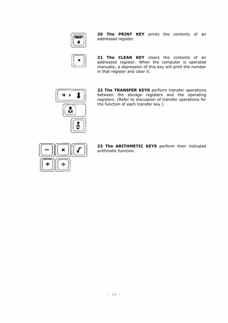
20 The PRINT KEY prints the contents of an
addressed register.
21 The CLEAR KEY clears the contents of an
addressed register. When the computer is operated
manually, a depression of this key will print the number
in that register and clear it.
22 The TRANSFER KEYS perform transfer operations
between the storage registers and the operating
registers. (Refer to discussion of transfer operations for
the function of each transfer key.)
23 The ARITHMETIC KEYS perform their indicated
arithmetic function.
- 14 -

Decimal Wheel
As it affects COMPUTATION:
The Decimal Wheel determines the number of decimal places to which
the result of a calculation in the A register will be carried out. The
Decimal Wheel has the following effect on these operations.
ADDITION, SUBTRACTION,
MULTIPLICATION:
After the computation, the result in the A
register is truncated according to the
number of decimal places indicated by the
setting of the Decimal Wheel. The complete
result is retained in the R register.
DIVISION: The quotient is retained in the A register and
is carried out only to the number of decimal
places indicated by the setting of the
Decimal Wheel.
The decimally correct remainder is retained
in the R register.
SQUARE ROOT: The root is retained in the A register and is
extracted to the number of decimal places
indicated by the setting 01 the Decimal
Wheel.
The R registerr contains a non-functional
remainder.
As it effects KEYBOARD ENTRIES:
When entering decimal numbers, the Decimal Point key is touched in its
proper position; e.g. to enter 12.6, enter 1. then 2, then touch the
Decimal Point key, and finally enter 6.
To enter numbers less than 1, a zero must be entered before the decimal
point; e.g.07 would be entered as 0.07.
Regardless of the setting of the Decimal Wheel, the complete figure
entered on the keyboard will be printed when the Start key or an
operation key is touched.
As it affects OUTPUT PRINTING:
All printed output, except that of the R register, is truncated to the setting
of the Decimal Wheel.
As it affects TRANSFER OPERATIONS:
Regardless of the setting of the Decimal Wheel, the complete figure in the
selected register will be transferred.
- 15 -
Split Register
/As was pointed out in the preceding pages, each of the B, C, 0, E and F registers can
be split into two parts, each with a capacity of 11 digits plus decimal point and sign. The left
part of the register is identified with the lower case letter corresponding to its companion's
designation. The lower case designation is obtained by entering the corresponding upper case
letter and touching the "I" key, e.g. c = C/o The right side of the split register retains its
original upper case letter designation.
The computer has built-in self-regulating circuitry that alerts the operator with an error light if
an attempt has been made to transfer a value larger than 11 digits to a split register, or to
split a register that already contains a value greater than 11 digits.
Nevertheless. a register can be used as both a whole and a split register at varying times
throughout a program by using the clear (*) instruction before shifting from whole to split or
vice versa. For example:
In phase one of a program, register B is used as a split register (b,B); then in phase two.
register B is to be used as a whole register:
1. At the end of phase 1, a B/* instruction frees the left side of the register so that in phase 2, it can be used in conjunction with the right side as a whole register.
2. At the end of phase 2, a B* instruction frees the whole register so that it can be used as a split register when the program starts again with phase 1.
- 16 –
General Operations
S Start-S
The instruction "S" (used in creating a program) directs the computer to stop and release the
keyboard for the entry of figures or the selection of a subroutine. After figure entry, the
program is restarted by touching the Start key (5).
The program can also be restarted by touching a Routine Selection key. When the "S"
instruction stops the program, the computer may also be operated in the manual mode
without disturbing the program instructions in memory. Any figures entered on the keyboard
before depression of Start or an operation key will be printed automatically.
* Clear
The clear operation "*" directs the computer to clear the selected register. The M and R
registers can not be cleared with this instruction.
When the computer is operated manually this key will also cause it to print the contents of the
selected register.
EXAMPLE: Assume register B contains 3.14159 prior to the execution of a B* instruction.
After execution of the instruction the register is blank. Note that the contents of other
registers are not affected.
______________________
M A R B
BEFORE 5.12 1.00 0.11 3.14159
B*
AFTER 5.12 1.00 0.11
The print "�" operation directs the computer to print the con~nts of the selected register
while retaining them in the register. The number of decimal places in the printed result is
controlled by the Decimal Wheel.
EXAMPLE:
A� results 2.71828 A�
B/� results 1.77245 b�
/� Vertical Spacing
The instruction "/�" directs the computer to advance the tape one vertical space, without
printing. - 17 -
Data Transfer Operations
� To A
An instruction containing the operation “ �" directs the computer to transfer the contents of the addressed register to A while retaining them in the original register. The contents of M and
R are not affected. The previous contents of A are destroyed. The setting of the Decimal Wheel
has no effect on this operation. ___________________________________________________ _____________________________ INSTRUCTION RESULT______________________________________
� M �A
R� R �A
A� Inoperative
b� b �A
B� B �A
c� c �A
C� C �A
d� d �A
D� D �A
e� e �A
E� E �A
f � f �A
F� F �A ___________________________________________________ ___________________________ EXAMPLE: Decimal Wheel set at 2.
___________________________
M A R B
BEFORE 24 36.05 48.123 12.00
R�
AFTER 24 48.123 48.123 12.00 ___________________________________________________ _____________________________ An example of using this instruction manually to transfer a value entered on the keyboara to
the A register would be to enter a figure on the keyboard (e.g. 1.141421) and then depress
the � key. After the � key is depressed, the data will be transferred to A and the computer
will print the number and the instruction, e.g. 1.141421 �. However, if the number had been
in a register (e.g. B) and that register were directed to transfer to A, the computer would print
only the instruction, e.g. B �.
- 18 -
� From M
An Insrruction containing the operation "�“ directs the computer to transfer the contents of
M to the addressed register while retaining them in M. The contents of registers A and R are
unaffected by this instruction. The original contents of the addressed register are destroyed.
The setting of the Decimal Wheel has no effect on this operation. ___________________________________________________ _____________________________ INSTRUCTION RESULT____________________________________________
� Inoperative
R � Inoperative
A � See discussion of Constants as instructions
b � M �b
B � M�B
c � M�c
C � M �C
d � M�d
D � M �D
e � M �e
E � M�E
f � M �f
F � M�F ___________________________________________________ ___________________________ EXAMPLE: Decimal Wheel set at 2.
____________________________
M A R B
BEFORE 19.333 5.00 16.00 30.00
B�
AFTER 19.333 5.00 16.00 19.333 ___________________________________________________ _____________________________ An example of using this instruction manually to store a number (e.g. 19.333) in the B
register would be to enter 19.333 on the keyboard and then depress the B and � keys. When
the � key is depressed, the data will be transferred to B and the computer will print both the
number and the instruction executed (e.g. 19.333 B�). If B/� were then manually
performed, the same value would be transferred from M to b and the instructions would print
on the tape to indicate that the number previously entered was also transferred to b (e.g.
b�).
- 19 -
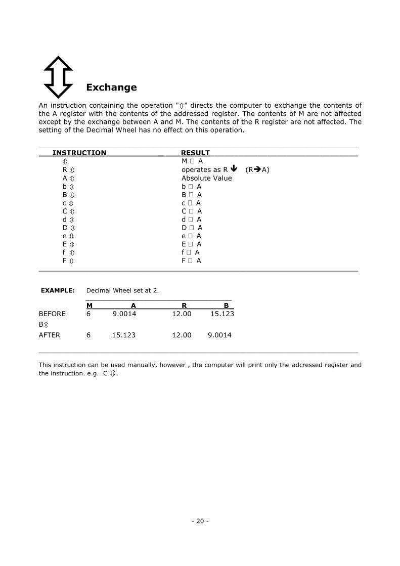
� Exchange
An instruction containing the operation "�" directs the computer to exchange the contents of
the A register with the contents of the addressed register. The contents of M are not affected
except by the exchange between A and M. The contents of the R register are not affected. The
setting of the Decimal Wheel has no effect on this operation.
___________________________________________________________________________________
INSTRUCTION _ RESULT_______________________________
� M ⇔ A R � operates as R � (R�A)
A � Absolute Value
b � b ⇔ A B � B ⇔ A c � c ⇔ A C � C ⇔ A d � d ⇔ A D � D ⇔ A e � e ⇔ A E � E ⇔ A f � f ⇔ A F � F ⇔ A
___________________________________________________________________________________
EXAMPLE: Decimal Wheel set at 2.
______________________________________
M A R B _
BEFORE 6 9.0014 12.00 15.123
B�
AFTER 6 15.123 12.00 9.0014
___________________________________________________________________________________
This instruction can be used manually, however , the computer will print only the adcressed register and
the instruction. e.g. C �.
- 20 -
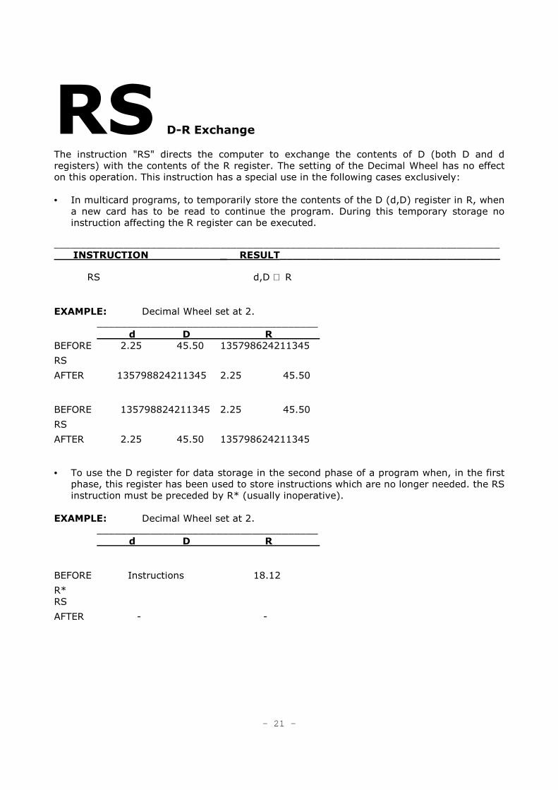
RS D-R Exchange
The instruction "RS" directs the computer to exchange the contents of D (both D and d
registers) with the contents of the R register. The setting of the Decimal Wheel has no effect
on this operation. This instruction has a special use in the following cases exclusively:
• In multicard programs, to temporarily store the contents of the D (d,D) register in R, when
a new card has to be read to continue the program. During this temporary storage no
instruction affecting the R register can be executed. ___________________________________________________________________________________
INSTRUCTION _ RESULT_________________________________
RS d,D ⇔ R
EXAMPLE: Decimal Wheel set at 2.
_____________________________________
d D R
BEFORE 2.25 45.50 135798624211345
RS
AFTER 135798824211345 2.25 45.50
BEFORE 135798824211345 2.25 45.50
RS
AFTER 2.25 45.50 135798624211345
• To use the D register for data storage in the second phase of a program when, in the first
phase, this register has been used to store instructions which are no longer needed. the RS
instruction must be preceded by R* (usually inoperative).
EXAMPLE: Decimal Wheel set at 2.
_____________________________________
d D R
BEFORE Instructions 18.12
R*
RS
AFTER - -
- 21 -
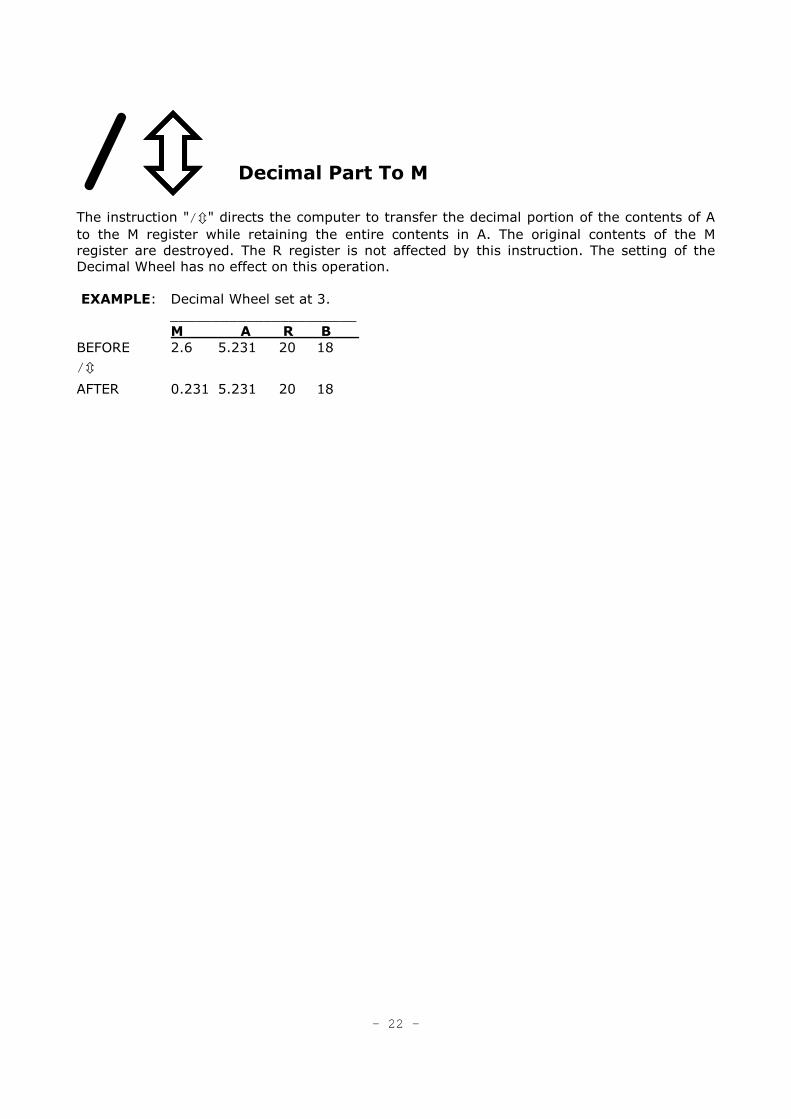
/���� Decimal Part To M
The instruction "/ �" directs the computer to transfer the decimal portion of the contents of A
to the M register while retaining the entire contents in A. The original contents of the M
register are destroyed. The R register is not affected by this instruction. The setting of the
Decimal Wheel has no effect on this operation.
EXAMPLE: Decimal Wheel set at 3.
______________________
M A R B
BEFORE 2.6 5.231 20 18
/ �
AFTER 0.231 5.231 20 18
- 22 -
Arithmetic Operations
All arithmetic operations are performed in the operating registers M, A and R. An arithmetic
operation is performed in two phases:
1. The contents of the selected register are automatically transferred to the M
register. The M register is selected automatically if no other register Is Indicated.
2. The operation Is carried out in the M, A and R registers
Programma 101 can perform these arithmetic operations: +, -, X, +, V. and absolute value.
Figures are accepted and computed algebraically. A negative value is entered by depressing
the negative key at any time during the entry of a figure. If there is no negative indication. the
computer will accept the figure as positive.
The Subtract operation key is separate from the numeric keyboard and is used exclusively for
subtraction.
These operations are described in detail in the following pages.
- 23 -
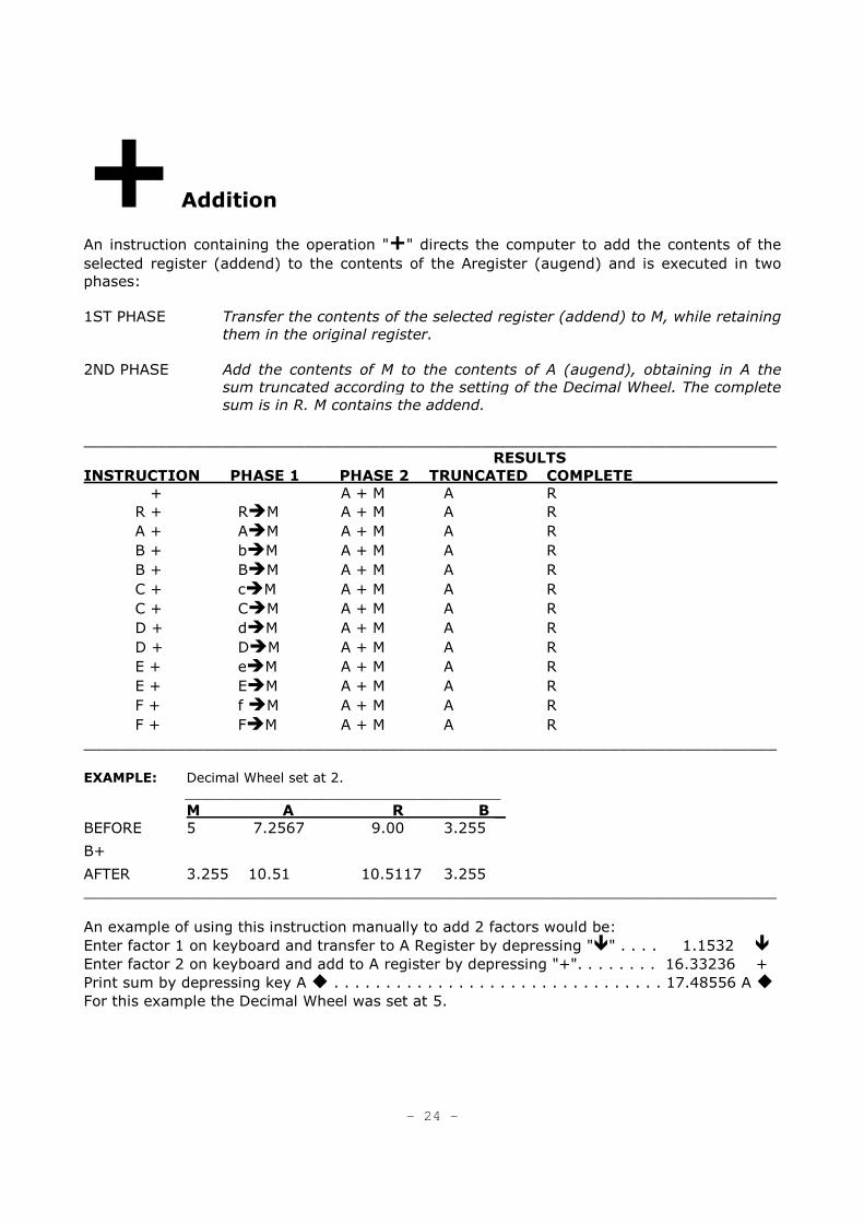
+ Addition
An instruction containing the operation "+" directs the computer to add the contents of the
selected register (addend) to the contents of the Aregister (augend) and is executed in two
phases:
1ST PHASE Transfer the contents of the selected register (addend) to M, while retaining
them in the original register.
2ND PHASE Add the contents of M to the contents of A (augend), obtaining in A the
sum truncated according to the setting of the Decimal Wheel. The complete
sum is in R. M contains the addend.
___________________________________________________________________________
RESULTS
INSTRUCTION PHASE 1 PHASE 2 TRUNCATED COMPLETE______________
+ A + M A R
R + R�M A + M A R
A + A�M A + M A R
B + b�M A + M A R
B + B�M A + M A R
C + c�M A + M A R
C + C�M A + M A R
D + d�M A + M A R
D + D�M A + M A R
E + e�M A + M A R
E + E�M A + M A R
F + f �M A + M A R
F + F�M A + M A R
___________________________________________________________________________
EXAMPLE: Decimal Wheel set at 2.
______________________________________
M A R B _
BEFORE 5 7.2567 9.00 3.255
B+
AFTER 3.255 10.51 10.5117 3.255
___________________________________________________________________________
An example of using this instruction manually to add 2 factors would be:
Enter factor 1 on keyboard and transfer to A Register by depressing "�" . . . . 1.1532 �
Enter factor 2 on keyboard and add to A register by depressing "+". . . . . . . . 16.33236 +
Print sum by depressing key A � . . . . . . . . . . . . . . . . . . . . . . . . . . . . . . . . 17.48556 A �
For this example the Decimal Wheel was set at 5.
- 24 -
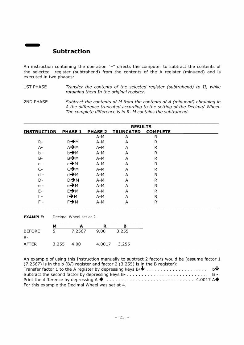
- Subtraction
An instruction containing the operation "-" directs the computer to subtract the contents of
the selected register (subtrahend) from the contents of the A register (minuend) and is
executed in two phaaes:
1ST PHASE Transfer the contents of the selected register (subtrahend) to II, while
ratalnlng them In the original register.
2ND PHASE Subtract the contents of M from the contents of A (minuend) obtaining in
A the difference truncated according to the setting of the Decima/ Wheel.
The complete difference is in R. M contains the subtrahend.
___________________________________________________________________________
RESULTS
INSTRUCTION PHASE 1 PHASE 2 TRUNCATED COMPLETE ____________
A-M A R
R- R�M A-M A R
A- A�M A-M A R
b - b�M A-M A R
B- B�M A-M A R
c - c�M A-M A R
C- C�M A-M A R
d - d�M A-M A R
D- D�M A-M A R
e - e�M A-M A R
E- E�M A-M A R
f - f�M A-M A R
F - F�M A-M A R
___________________________________________________________________________
EXAMPLE: Decimal Wheel set at 2.
______________________________________
M A R B _
BEFORE 5 7.2567 9.00 3.255
B-
AFTER 3.255 4.00 4.0017 3.255
___________________________________________________________________________
An example of using this Instruction manually to subtract 2 factors would be (assume factor 1
(7.2567) is in the b (B/) register and factor 2 (3.255) is in the B register):
Transfer factor 1 to the A register by depressing keys B/� . . . . . . . . . . . . . . . . . . . . . b�
Subtract the second factor by depressing keys B- . . . . . . . . . . . . . . . . . . . . . . . . . . . . B -
Print the difference by depressing A � . . . . . . . . . . . . . . . . . . . . . . . . . . . . . . 4.0017 A�
For this example the Decimal Wheel was set at 4.
- 25 -
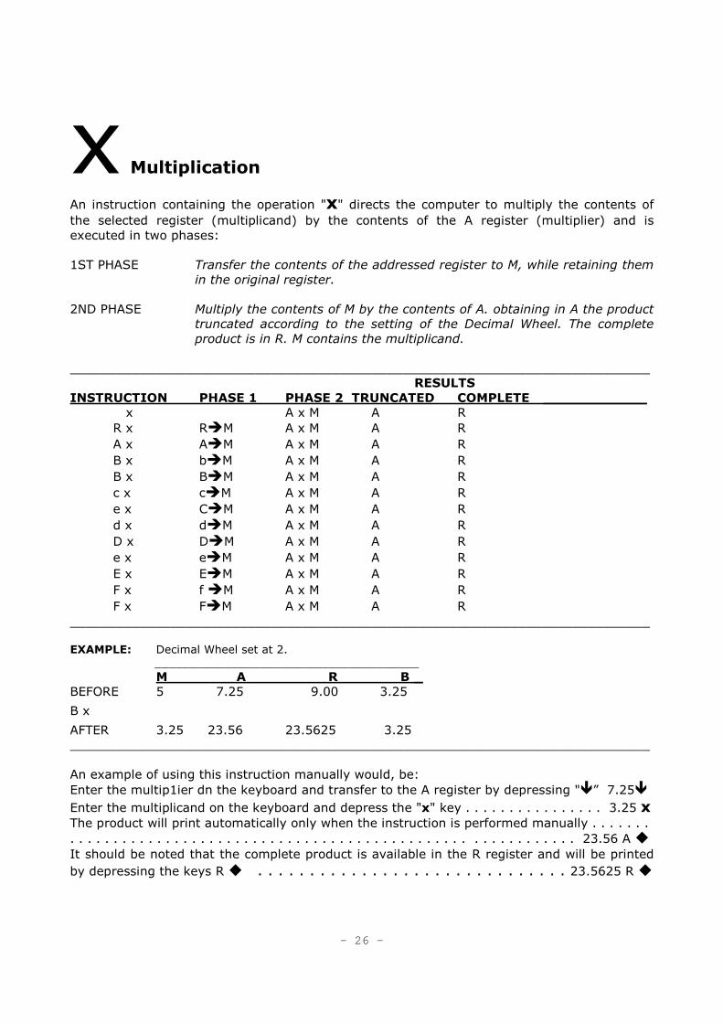
x Multiplication
An instruction containing the operation "x" directs the computer to multiply the contents of
the selected register (multiplicand) by the contents of the A register (multiplier) and is
executed in two phases:
1ST PHASE Transfer the contents of the addressed register to M, while retaining them
in the original register.
2ND PHASE Multiply the contents of M by the contents of A. obtaining in A the product
truncated according to the setting of the Decimal Wheel. The complete
product is in R. M contains the multiplicand.
___________________________________________________________________________
RESULTS
INSTRUCTION PHASE 1 PHASE 2 TRUNCATED COMPLETE ____________
x A x M A R
R x R�M A x M A R
A x A�M A x M A R
B x b�M A x M A R
B x B�M A x M A R
c x c�M A x M A R
e x C�M A x M A R
d x d�M A x M A R
D x D�M A x M A R
e x e�M A x M A R
E x E�M A x M A R
F x f �M A x M A R
F x F�M A x M A R
___________________________________________________________________________ EXAMPLE: Decimal Wheel set at 2.
______________________________________
M A R B _
BEFORE 5 7.25 9.00 3.25
B x
AFTER 3.25 23.56 23.5625 3.25
___________________________________________________________________________
An example of using this instruction manually would, be:
Enter the multip1ier dn the keyboard and transfer to the A register by depressing "�” 7.25�
Enter the multiplicand on the keyboard and depress the "x" key . . . . . . . . . . . . . . . . 3.25 x The product will print automatically only when the instruction is performed manually . . . . . . .
. . . . . . . . . . . . . . . . . . . . . . . . . . . . . . . . . . . . . . . . . . . . . . . . . . . . . . . . . . 23.56 A �
It should be noted that the complete product is available in the R register and will be printed
by depressing the keys R � . . . . . . . . . . . . . . . . . . . . . . . . . . . . . . 23.5625 R �
- 26 -
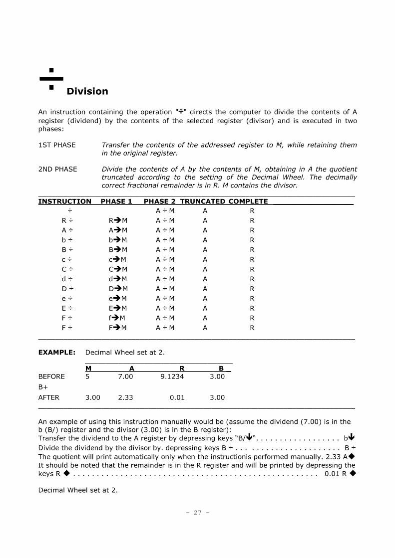
÷÷÷÷ Division
An instruction containing the operation "÷÷÷÷" directs the computer to divide the contents of A
register (dividend) by the contents of the selected register (divisor) and is executed in two
phases:
1ST PHASE Transfer the contents of the addressed register to M, while retaining them
in the original register.
2ND PHASE Divide the contents of A by the contents of M, obtaining in A the quotient
truncated according to the setting of the Decimal Wheel. The decimally
correct fractional remainder is in R. M contains the divisor.
___________________________________________________________________________
INSTRUCTION PHASE 1 PHASE 2 TRUNCATED COMPLETE _________________
÷ A ÷ M A R
R ÷ R�M A ÷ M A R
A ÷ A�M A ÷ M A R
b ÷ b�M A ÷ M A R
B ÷ B�M A ÷ M A R
c ÷ c�M A ÷ M A R
C ÷ C�M A ÷ M A R
d ÷ d�M A ÷ M A R
D ÷ D�M A ÷ M A R
e ÷ e�M A ÷ M A R
E ÷ E�M A ÷ M A R
F ÷ f�M A ÷ M A R
F ÷ F�M A ÷ M A R
___________________________________________________________________________
EXAMPLE: Decimal Wheel set at 2.
___________________________________
M A R B _
BEFORE 5 7.00 9.1234 3.00
B+
AFTER 3.00 2.33 0.01 3.00
___________________________________________________________________________
An example of using this instruction manually would be (assume the dividend (7.00) is in the
b (B/) register and the divisor (3.00) is in the B register):
Transfer the dividend to the A register by depressing keys “B/�“. . . . . . . . . . . . . . . . . . b�
Divide the dividend by the divisor by. depressing keys B ÷ . . . . . . . . . . . . . . . . . . . . . . B ÷ The quotient will print automatically only when the instructionis performed manually. 2.33 A�
It should be noted that the remainder is in the R register and will be printed by depressing the
keys R � . . . . . . . . . . . . . . . . . . . . . . . . . . . . . . . . . . . . . . . . . . . . . . . . . . . . 0.01 R �
Decimal Wheel set at 2.
- 27 -
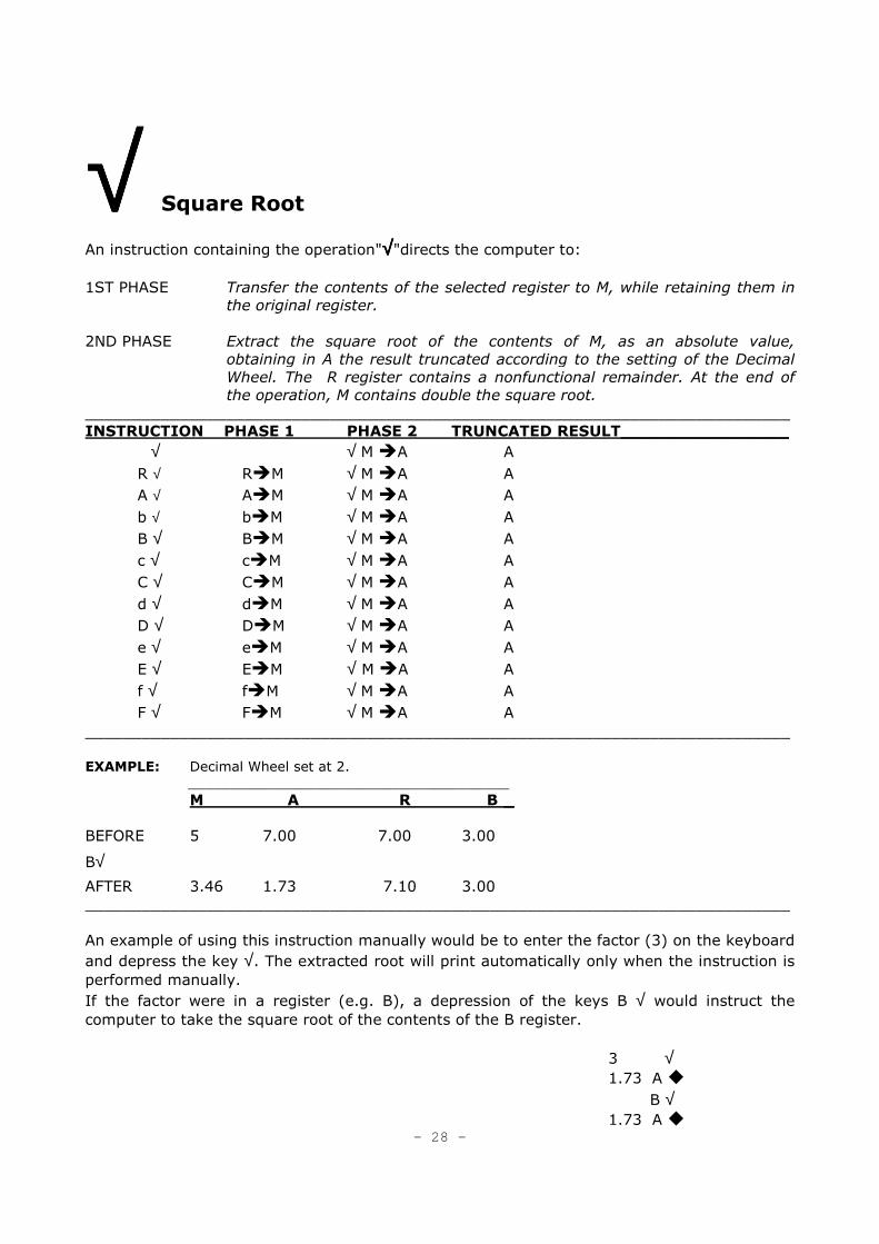
√√√√ Square Root
An instruction containing the operation"√√√√"directs the computer to:
1ST PHASE Transfer the contents of the selected register to M, while retaining them in
the original register.
2ND PHASE Extract the square root of the contents of M, as an absolute value,
obtaining in A the result truncated according to the setting of the Decimal
Wheel. The R register contains a nonfunctional remainder. At the end of
the operation, M contains double the square root.
___________________________________________________________________________
INSTRUCTION PHASE 1 PHASE 2 TRUNCATED RESULT________________
√ √ M �A A
R √ R�M √ M �A A
A √ A�M √ M �A A
b √ b�M √ M �A A
B √ B�M √ M �A A
c √ c�M √ M �A A
C √ C�M √ M �A A
d √ d�M √ M �A A
D √ D�M √ M �A A
e √ e�M √ M �A A
E √ E�M √ M �A A
f √ f�M √ M �A A
F √ F�M √ M �A A
___________________________________________________________________________
EXAMPLE: Decimal Wheel set at 2.
______________________________________
M A R B _
BEFORE 5 7.00 7.00 3.00
B√
AFTER 3.46 1.73 7.10 3.00
___________________________________________________________________________
An example of using this instruction manually would be to enter the factor (3) on the keyboard
and depress the key √. The extracted root will print automatically only when the instruction is
performed manually.
If the factor were in a register (e.g. B), a depression of the keys B √ would instruct the computer to take the square root of the contents of the B register.
3 √ 1.73 A �
B √ 1.73 A �
- 28 -
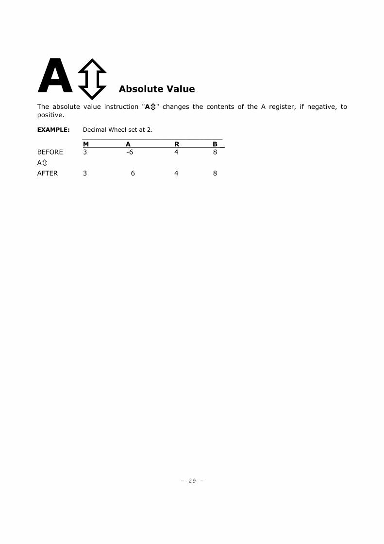
A���� Absolute Value
The absolute value instruction "A����" changes the contents of the A register, if negative, to
positive. EXAMPLE: Decimal Wheel set at 2.
______________________________________
M A R B _
BEFORE 3 -6 4 8
A�
AFTER 3 6 4 8
- 29 -
Jump Operations
The Jump operation directs the computer to depart from the normal sequence of step-by-step
instructions and jump to a pre-selected point in the program.
These instructions provide both internal and external (manual) decision capability and are
useful to:
• Create "loops" that allow repetitive sequences in a program to be executed.
• Select alternate routines or subroutines at the discretion of the operator.
• Automatically "branch" to alternate routines or subroutines according to the value
in the "A" register.
The jump operation requires two related instructions:
1. Point of origin: where to start the jump, Interrupting the sequence.
2. Reference point: where the jump will arrive, restarting the sequence.
There are two types of jump instructions:
• Unconditional jumps
• Conditional Jumps
- 30 -
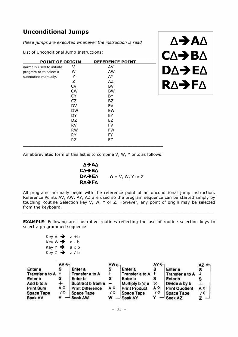
Unconditional Jumps
these jumps are executed whenever the instruction is read
List of Unconditional Jump Instructions:
____________________________________________________
______POINT OF ORIGIN REFERENCE POINT_______
normally used to initiate V AV
program or to select a W AW
subroutine manually. Y AY
Z AZ
CV BV
CW BW
CY BY
CZ BZ
DV EV
DW EW
DY EY
DZ EZ
RV FV
RW FW
RY FY
RZ FZ
_______________________________________________________
An abbreviated form of this list is to combine V, W, Y or Z as follows:
∆ ∆ ∆ ∆����A∆∆∆∆ C∆∆∆∆����B∆∆∆∆ D∆∆∆∆����E∆ ∆∆ ∆∆ ∆∆ ∆ = V, W, Y or Z R∆∆∆∆����F∆∆∆∆
All programs normally begin with the reference point of an unconditional jump instruction.
Reference Points AV, AW, AY, AZ are used so the program sequence can be started simply by
touching Routine Selection key V, W, Y or Z. However, any point of origin may be selected
from the keyboard.
___________________________________________________________________________
EXAMPLE: Following are illustrative routines reflecting the use of routine selection keys to
select a programmed sequence:
Key V � � � � a +b
Key W � � � � a - b
Key Y � � � � a x b
Key Z � � � � a / b
- 31 -
∆ ∆ ∆ ∆����A∆∆∆∆ C∆∆∆∆����B∆∆∆∆ D∆∆∆∆����E∆∆∆∆ R∆∆∆∆����F∆∆∆∆
Conditional Jumps
these jumps choose one of two alternatives by testing the
contents of the A register for the fol/owing condition:
If the contents of the A register are:
GREATER THAN 0 - the program jumps to the corresponding
Reference Point.
ZERO OR LESS - the program continues with the next
instruction in sequence.
List of Conditional Jump Instructions:
____________________________________________________
______POINT OF ORIGIN REFERENCE POINT_______
/V aV
/W aW
/Y aY
/Z aZ
cV bV
cW bW
cY bY
cZ bZ
dV eV
dW eW
dY eY
dZ eZ
rV fV
rW fW
rY fY
rZ fZ
_______________________________________________________
The lower case letters shown in the above lists are obtained by entering the corresponding
upper case letter and touching the “/" key, e.g. r = R/.
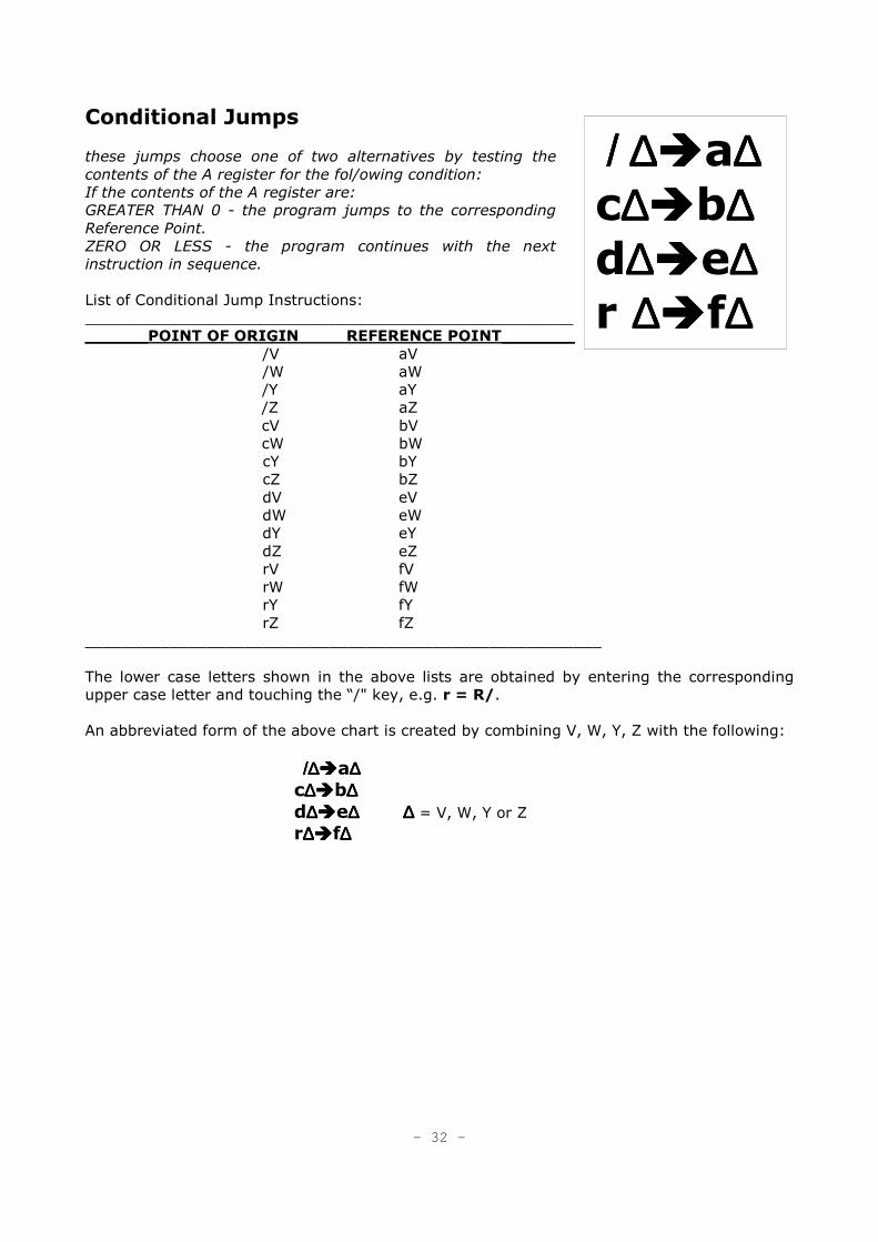
An abbreviated form of the above chart is created by combining V, W, Y, Z with the following:
/∆ /∆ /∆ /∆����a∆∆∆∆ c∆∆∆∆����b∆∆∆∆ d∆∆∆∆����e∆ ∆∆ ∆∆ ∆∆ ∆ = V, W, Y or Z r∆∆∆∆����f∆∆∆∆
- 32 -
/ ∆ / ∆ / ∆ / ∆����a∆∆∆∆ c∆∆∆∆����b∆∆∆∆ d∆∆∆∆����e∆∆∆∆ r ∆∆∆∆����f∆∆∆∆
The Conditional Jump can not directly differentiate between a negative value and zero. If the A
register has a negative value, the distinction may be made by a two-test procedure:
1. The value of A is tested. If the jump occurs, this value is positive; if the jump does not
occur, the A���� (absolute value) instruction is executed.
2. The value of A is again tested. If the jump occurs, the value is negative. If the jump does
not occur the value is zero. If necessary, the program can re-establish the initial algebraic
condition of A.
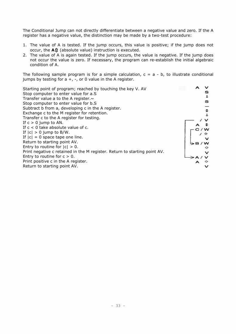
The following sample program is for a simple calculation, c = a - b, to illustrate conditional
jumps by testing for a +, -, or 0 value in the A register.
Starting point of program; reached by touching the key V. AV
Stop computer to enter value for a.S
Transfer value a to the A register.~
Stop computer to enter value for b.S
Subtract b from a, developing c in the A register.
Exchange c to the M register for retention.
Transfer c to the A register for testing.
If c > 0 jump to AN.
If c < 0 take absolute value of c.
If |c| > 0 jump to B/W.
If |c| = 0 space tape one line.
Return to starting point AV.
Entry to routine for |c| > 0.
Print negative c retained in the M register. Return to starting point AV.
Entry to routine for c > 0.
Print positive c in the A register.
Return to starting point AV.
- 33 -
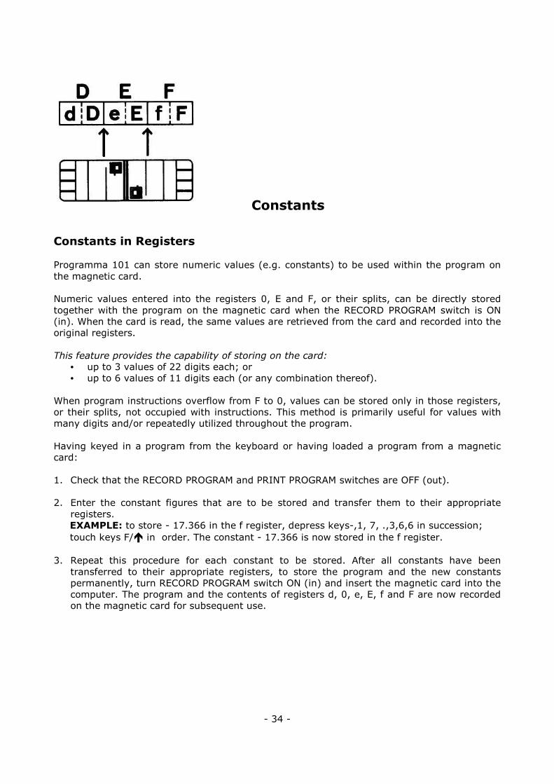
Constants
Constants in Registers
Programma 101 can store numeric values (e.g. constants) to be used within the program on
the magnetic card.
Numeric values entered into the registers 0, E and F, or their splits, can be directly stored
together with the program on the magnetic card when the RECORD PROGRAM switch is ON
(in). When the card is read, the same values are retrieved from the card and recorded into the
original registers.
This feature provides the capability of storing on the card:
• up to 3 values of 22 digits each; or
• up to 6 values of 11 digits each (or any combination thereof).
When program instructions overflow from F to 0, values can be stored only in those registers,
or their splits, not occupied with instructions. This method is primarily useful for values with
many digits and/or repeatedly utilized throughout the program.
Having keyed in a program from the keyboard or having loaded a program from a magnetic
card:
1. Check that the RECORD PROGRAM and PRINT PROGRAM switches are OFF (out).
2. Enter the constant figures that are to be stored and transfer them to their appropriate
registers.
EXAMPLE: to store - 17.366 in the f register, depress keys-,1, 7, .,3,6,6 in succession;
touch keys F/� in order. The constant - 17.366 is now stored in the f register.
3. Repeat this procedure for each constant to be stored. After all constants have been transferred to their appropriate registers, to store the program and the new constants
permanently, turn RECORD PROGRAM switch ON (in) and insert the magnetic card into the
computer. The program and the contents of registers d, 0, e, E, f and F are now recorded
on the magnetic card for subsequent use.
- 34 -
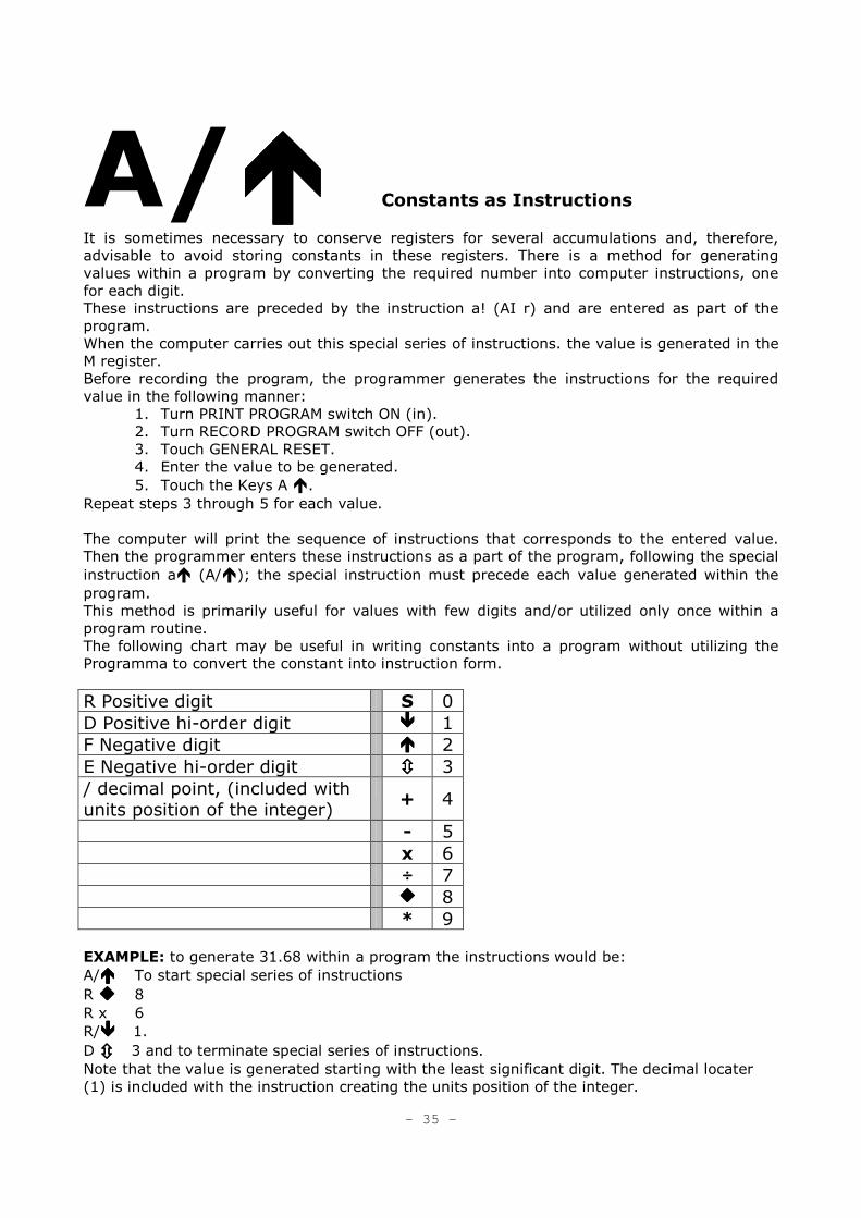
A/���� Constants as Instructions
It is sometimes necessary to conserve registers for several accumulations and, therefore,
advisable to avoid storing constants in these registers. There is a method for generating
values within a program by converting the required number into computer instructions, one
for each digit.
These instructions are preceded by the instruction a! (AI r) and are entered as part of the
program.
When the computer carries out this special series of instructions. the value is generated in the
M register.
Before recording the program, the programmer generates the instructions for the required
value in the following manner:
1. Turn PRINT PROGRAM switch ON (in). 2. Turn RECORD PROGRAM switch OFF (out). 3. Touch GENERAL RESET. 4. Enter the value to be generated. 5. Touch the Keys A �.
Repeat steps 3 through 5 for each value.
The computer will print the sequence of instructions that corresponds to the entered value.
Then the programmer enters these instructions as a part of the program, following the special
instruction a� (A/�); the special instruction must precede each value generated within the
program.
This method is primarily useful for values with few digits and/or utilized only once within a
program routine.
The following chart may be useful in writing constants into a program without utilizing the
Programma to convert the constant into instruction form.
R Positive digit S 0
D Positive hi-order digit ���� 1
F Negative digit ���� 2
E Negative hi-order digit ���� 3
/ decimal point, (included with units position of the integer)
+ 4
- 5
x 6
÷÷÷÷ 7
���� 8
* 9
EXAMPLE: to generate 31.68 within a program the instructions would be:
A/���� To start special series of instructions
R ���� 8
R x 6
R/� � � � 1.
D � � � � 3 and to terminate special series of instructions.
Note that the value is generated starting with the least significant digit. The decimal locater
(1) is included with the instruction creating the units position of the integer.
- 35 -
Computer Utilization
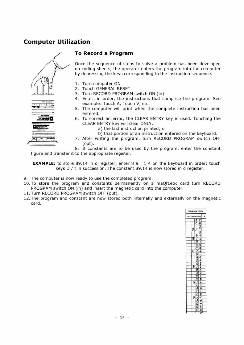
To Record a Program
Once the sequence of steps to solve a problem has been developed
on coding sheets, the operator enters the program into the computer
by depressing the keys corresponding to the instruction sequence.
1. Turn computer ON
2. Touch GENERAL RESET 3. Turn RECORD PROGRAM switch ON (in). 4. Enter, in order, the instructions that comprise the program. See
example: Touch A, Touch V, etc.
5. The computer will print when the complete instruction has been
entered.
6. To correct an error, the CLEAR ENTRY key is used. Touching the CLEAR ENTRY key will clear ONLY:
a) the last instruction printed; or b) that portion of an instruction entered on the keyboard.
7. After writing the program, turn RECORD PROGRAM switch OFF
(out).
8. If constants are to be used by the program, enter the constant
figure and transfer it to the appropriate register.
EXAMPLE: to store 89.14 in d register, enter 8 9 . 1 4 on the keyboard in order; touch
keys D / t in succession. The constant 89.14 is now stored in d register.
9. The computer is now ready to use the completed progrem.
10. To store the program and constants permanently on a maQf1etic card turn RECORD
PROGRAM switch ON (in) and insert the magnetic card into the computer.
11. Turn RECORD PROGRAM switch OFF (out). 12. The program and constant are now stored both internally and externally on the magnetic
card.
- 36 -
Read/Record D and E
Constants and instructions: 1) can be entered from the keyboard directly into registers E and
D; 2) can be recorded from only registers E and D onto a card; or; 3) read from a card only
into registers E and D, without affecting the contents of other program registers. This
technique can be utilized most effectively for the creation and use of subroutine or module
programs.
1. 1 To enter instructions from the keyboard directly into registers E and D, completely by-
passing instruction registers 1 and 2, and storage register F:
Turn computer ON;
Touch GENERAL RESET;
Turn RECORD PROGRAM switch ON (in);
Turn PRINT PROGRAM switch ON (in);
Enter, in order, the instructions that comprise the subroutine or modular program;
The instructions will be received first by E, then e, than D, then d (if the maximum
capacity of 48 instructions are utilized).
2. If the information in the D and E registers is to be recorded onto a magnetic card:
BOTH the RECORD PROGRAM switch and the PRINT PROGRAM switch must be ON (in);
Insert magnetic card;
The transfer of information will be from the D and E registers of the memory to the
program card.
3. If the contents of a card are to be read only into the D and E registers: The PRINT PROGRAM switch is tumed ON (in) and the program card is inserted: Information is read
into the D and E registers exclusively;
The contents of the other registers are unaffected.
To Print a Program
Once a program has been recorded on a magnetic card, the entire sequence of instructions
forming the program can be printed out. This is normally used to analyze a new program to
insure correct entry, or to locate an error in the program.
1. To locate the initial instruction of a program, insert the program card.
2. Turn PRINT PROGRAM ON (in); touch the Print key (0). 3. The computer will print the instructions in their programmed sequence.
4. The computer will stop at each Stop (S) instruction. To continue the printing of the
instructions, touch the Print key (����).
5. When the entire program has been printed, turn PRINT PROGRAM OFF (out). To locate an
error within a program, after the Error light has gone on, follow steps 2 through 5 above.
This prints. the instructions from the present location in the program. The ihstructiofl
immediately preceding the first printed instruction caused the activation of the Error light.
- 37 -
To Use a Program
1. Turn computer ON.
2. Touch GENERAL RESET. 3. Turn RECORD PROGRAM and PRINT PROGRAM switches OFF (out). 4 Set DECIMAL WHEEL
to desired position.
4. Insert the program card into the computer. The program card can be removed from the
computer at any time, since the program is transferred directly to the memory. If the
program is to be repeated, the program card need not be reinserted since the program
remains in the computer.
5. Depress the proper ROUTINE SELECTION key. 6. Operations will occur as explained in the operating procedure. The keyboard will lock
during computations. When variable factors are to be entered, the program will stop and
the keyboard will be unlocked to permit data entry.
Automatic Internal Checks
Programma 101 provides a system of automatic internal checks to assure the operator that all
components are functioning properly. The red ERROR light is the visual indication that a mis-
operation has been detected.
When a magnetic program card is misread, the error indicated is usually either the result of a
damaged or dirty card, or the improper insertion of the card.
examine the physical condition of the card and if there is
no evidence of damage, reinsert the card properly.
The following mis-operations are indicated by the Error light:
• Capacity exceeded by computation. The original contents of registers A and R are
destroyed.
• Capacity of a split register exceeded by a transfer. The transfer is not performed.
• Division by zero.
• Keyboard entry capacity exceeded. To repeat the entry correctly, the clear entry key must
first be depressed.
• An erroneous attempt has been made to store data and instructions in the same register.
(See discussion of storage of data and instructions in the same register).
the following steps provide the information basic to the analysis of the above errors:
• print out all registers
• print out program from point of error (the instruction immediately preceding the first
printed instruction is the operation that caused the error)
• print out the complete program
- 38 -
Manual Mode
Programma 101 can be operated manually as an electronic calculator. The rules given in the
preceding pages for computer instructions apply also to manual operations with the following
exceptions:
1. The results of multiplication, division and square root will be printed automatically.
2. The results of addition and subtraction will be printed only by touching the keys A and ����
in sequence.
3. The * key when touched will cause both printing and clearing of the selected register
(except M and R).
The computer can also be operated manually. while it is being used in program mode. at any
stop instruction in the program. In this case, the operator should be careful when entering
figures in the registers not to affect the contents of the registers used by the program.
- 39 -
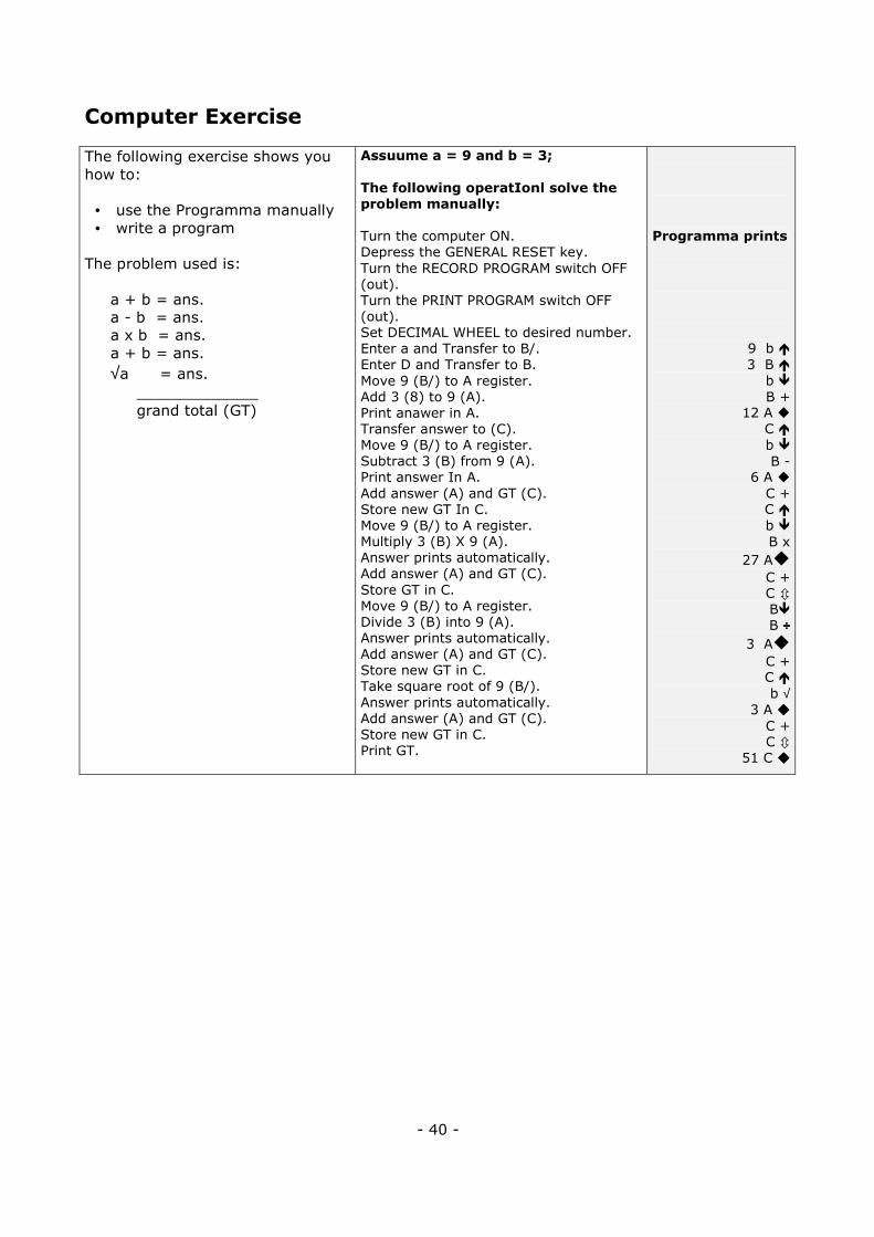
Computer Exercise
The following exercise shows you
how to:
• use the Programma manually
• write a program
The problem used is:
a + b = ans.
a - b = ans.
a x b = ans.
a + b = ans.
√a = ans. _____________
grand total (GT)
Assuume a = 9 and b = 3;
The following operatIonl solve the
problem manually:
Turn the computer ON.
Depress the GENERAL RESET key.
Turn the RECORD PROGRAM switch OFF
(out).
Turn the PRINT PROGRAM switch OFF
(out).
Set DECIMAL WHEEL to desired number.
Enter a and Transfer to B/.
Enter D and Transfer to B.
Move 9 (B/) to A register.
Add 3 (8) to 9 (A).
Print anawer in A.
Transfer answer to (C).
Move 9 (B/) to A register.
Subtract 3 (B) from 9 (A).
Print answer In A.
Add answer (A) and GT (C).
Store new GT In C.
Move 9 (B/) to A register.
Multiply 3 (B) X 9 (A).
Answer prints automatically.
Add answer (A) and GT (C).
Store GT in C.
Move 9 (B/) to A register.
Divide 3 (B) into 9 (A).
Answer prints automatically.
Add answer (A) and GT (C).
Store new GT in C.
Take square root of 9 (B/).
Answer prints automatically.
Add answer (A) and GT (C).
Store new GT in C.
Print GT.
Programma prints
9 b �
3 B �
b �
B + 12 A �
C �
b �
B - 6 A �
C + C �
b �
B x
27 A�
C + C � B� B ÷÷÷÷
3 A�
C + C �
b √ 3 A ����
C + C � 51 C ����
- 40 -
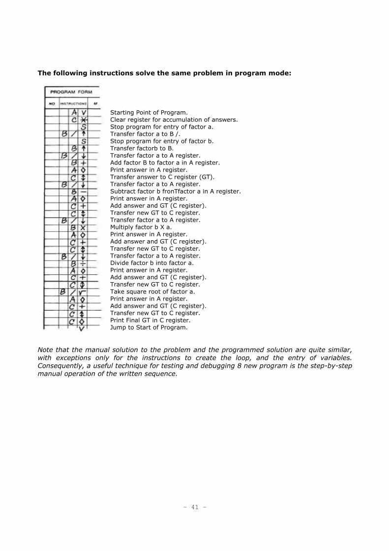
The following instructions solve the same problem in program mode:
Starting Point of Program.
Clear register for accumulation of answers.
Stop program for entry of factor a.
Transfer factor a to B /.
Stop program for entry of factor b.
Transfer factorb to B.
Transfer factor a to A register.
Add factor B to factor a in A register.
Print answer in A register.
Transfer answer to C register (GT).
Transfer factor a to A register.
Subtract factor b fronTfactor a in A register.
Print answer in A register.
Add answer and GT (C register).
Transfer new GT to C register.
Transfer factor a to A register.
Multiply factor b X a.
Print answer in A register.
Add answer and GT (C register).
Transfer new GT to C register.
Transfer factor a to A register.
Divide factor b into factor a.
Print answer in A register.
Add answer and GT (C register).
Transfer new GT to C register.
Take square root of factor a.
Print answer in A register.
Add answer and GT (C register).
Transfer new GT to C register.
Print Final GT in C register.
Jump to Start of Program.
Note that the manual solution to the problem and the programmed solution are quite similar,
with exceptions only for the instructions to create the loop, and the entry of variables.
Consequently, a useful technique for testing and debugging 8 new program is the step-by-step
manual operation of the written sequence.
- 41 -
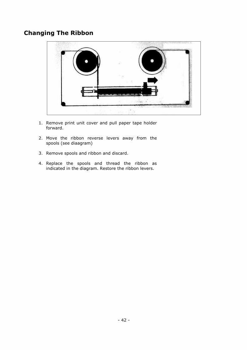
Changing The Ribbon
1. Remove print unit cover and pull paper tape holder
forward.
2. Move the ribbon reverse levers away from the
spools (see diaagram)
3. Remove spools and ribbon and discard.
4. Replace the spools and thread the ribbon as
indicated in the diagram. Restore the ribbon levers.
- 42 -
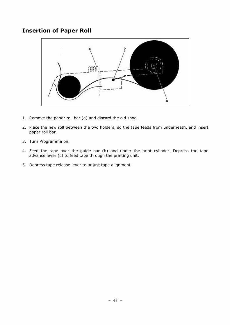
Insertion of Paper Roll
1. Remove the paper roll bar (a) and discard the old spool.
2. Place the new roll between the two holders, so the tape feeds from underneath, and insert
paper roll bar.
3. Turn Programma on.
4. Feed the tape over the guide bar (b) and under the print cylinder. Depress the tape advance lever (c) to feed tape through the printing unit.
5. Depress tape release lever to adjust tape alignment.
- 43 -
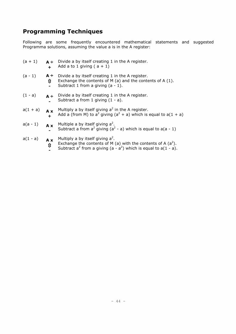
Programming Techniques
Following are some frequently encountered mathematical statements and suggested
Programma solutions, assuming the value a is in the A register:
(a + 1)
(a - 1)
(1 - a)
a(1 + a)
a(a - 1)
a(1 - a)
A ÷÷÷÷ +
A ÷÷÷÷ ���� -
A ÷÷÷÷ -
A x
+
A x
-
A x
���� -
Divide a by itself creating 1 in the A register.
Add a to 1 giving ( a + 1)
Divide a by itself creating 1 in the A register.
Exchange the contents of M (a) and the contents of A (1).
Subtract 1 from a giving (a - 1).
Divide a by itself creating 1 in the A register.
Subtract a from 1 giving (1 - a).
Multiply a by itself giving a2 in the A register.
Add a (from M) to a2 giving (a2 + a) which is equal to a(1 + a)
Multiple a by itself giving a2.
Subtract a from a2 giving (a2 - a) which is equal to a(a - 1)
Multiply a by itself giving a2.
Exchange the contents of M (a) with the contents of A (a2).
Subtract a2 from a giving (a - a2) which is equal to a(1 - a).
- 44 -
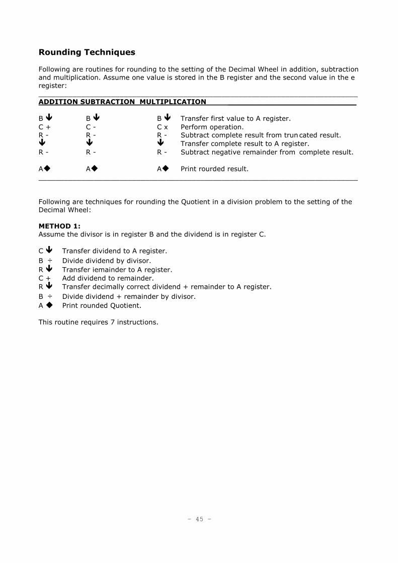
Rounding Techniques
Following are routines for rounding to the setting of the Decimal Wheel in addition, subtraction
and multiplication. Assume one value is stored in the B register and the second value in the e
register:
___________________________________________________________________________
ADDITION SUBTRACTION MULTIPLICATION ___________________________
B � B � B � Transfer first value to A register.
C + C - C x Perform operation.
R - R - R - Subtract complete result from trun cated result.
� � � Transfer complete result to A register.
R - R - R - Subtract negative remainder from complete result.
A� A� A� Print rourded result.
___________________________________________________________________________
Following are techniques for rounding the Quotient in a division problem to the setting of the
Decimal Wheel:
METHOD 1:
Assume the divisor is in register B and the dividend is in register C.
C � Transfer dividend to A register.
B ÷ Divide dividend by divisor.
R � Transfer iemainder to A register.
C + Add dividend to remainder.
R � Transfer decimally correct dividend + remainder to A register.
B ÷ Divide dividend + remainder by divisor.
A � Print rounded Quotient.
This routine requires 7 instructions.
- 45 -
METHOD 2:
Assume the divisor is in register B and the dividend is in register A.
A + Double dividend.
B ÷ Divide doubled dividend by the divisor.
A/ � Special series to generate 2 in the M register.
D/ �
÷ Divide doubled quotient by 2.
R + Round off.
A � Print rounded quotient.
This routine requires 7 instructions.
Following is a technique for rounding to some position lower than the setting of the Decimal
Wheel, e.g., round to 2 places when the Decimal Wheel is at 5. At the point where the routine
begins, assume the operation has been completed and the value to be rounded is in the A
register.
D/x Multiply the contents of the A register by 102 to shift decimal.
/� Transfer the decimal portion of the contents of A to M;
+ Add decimal portion to contents of A.
/� Transfer the decimal portion of the contents of A to M.
- Subtract decimal portion from the contents of A.
D/÷ Divide the contents of the A register by 102 to shift the decimal.
A � Print rounded answer.
This routine requires 7 instructions and 1 register containing a constant 10n where n is equal
to the position to which rounding is desired.
- 46 -
Instruction - Data Storage
Storage of data and instructions in the same half of a register. A technique has been
developed which allows the storage of both a number and program instructions in the same
half of a register (F, f, E, e, D, d).
This technique permits the programmer to address a register having both a number and
instructions in it, and perform any transfer, arithmetic, print or clear operation with the
number - without disturbing the instructions in that register and without getting an error light.
The number, which may be either a constant or accumulation, must precede the instructions
and must not exceed the space allotted for it. For this purpose, the registers should be
considered as 24 digit registers with the upper half (F, E, D) containing positions 1-12 and the
lower half (f, e, d) containing positions 13-24. A two digit number in the upper half of a
register would thus occupy positions 1 and 2. A two digit number in the lower half would
occupy positions 13 and 14.
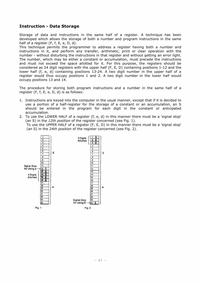
The procedure for storing both program instructions and a number in the same half of a
register (F, f, E, e, D, d) is as follows:
1. Instructions are keyed into the computer in the usual manner, except that if it is decided to
use a portion of a half-register for the storage of a constant or an accumulation, an S
should be entered in the program for each digit in the constant or anticipated
accumulation.
2. To use the LOWER HALF of a register (f, e, d) in this manner there must be a 'signal stop'
(an S) in the 12th position of the register concerned (see Fig. 1).
To use the UPPER HALF of a register (F, E, D) in this manner there must be a 'signal stop'
(an S) in the 24th position of the register concerned (see Fig. 2).
- 47 -
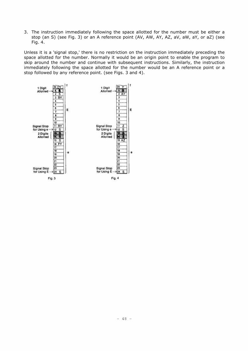
3. The instruction immediately following the space allotted for the number must be either a
stop (an S) (see Fig. 3) or an A reference point (AV, AW, AY, AZ, aV, aW, aY, or aZ) (see
Fig. 4.
Unless it is a 'signal stop,' there is no restriction on the instruction immediately preceding the
space allotted for the number. Normally it would be an origin point to enable the program to
skip around the number and continue with subsequent instructions. Similarly, the instruction
immediately following the space allotted for the number would be an A reference point or a
stop followed by any reference point. (see Figs. 3 and 4).
- 48 -
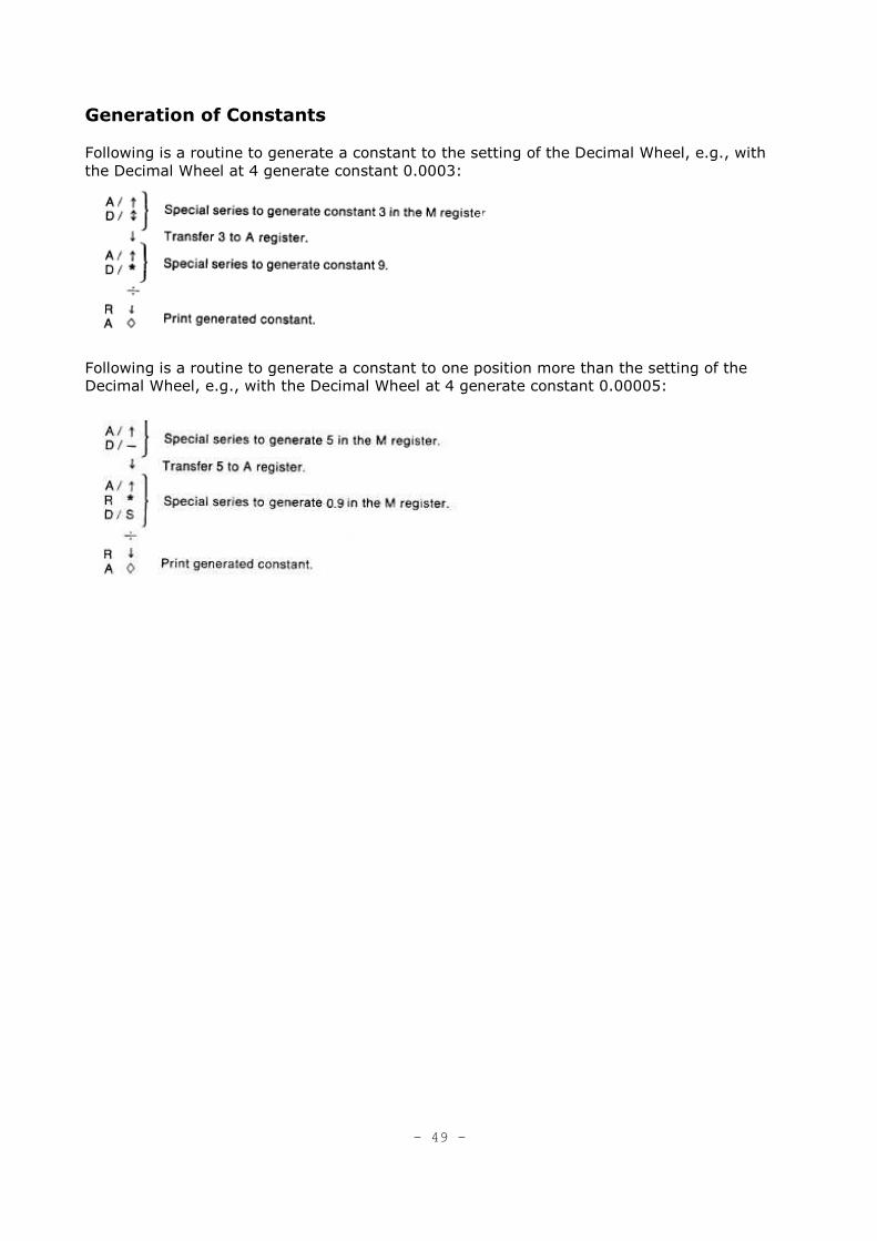
Generation of Constants
Following is a routine to generate a constant to the setting of the Decimal Wheel, e.g., with
the Decimal Wheel at 4 generate constant 0.0003:
Following is a routine to generate a constant to one position more than the setting of the
Decimal Wheel, e.g., with the Decimal Wheel at 4 generate constant 0.00005:
- 49 -
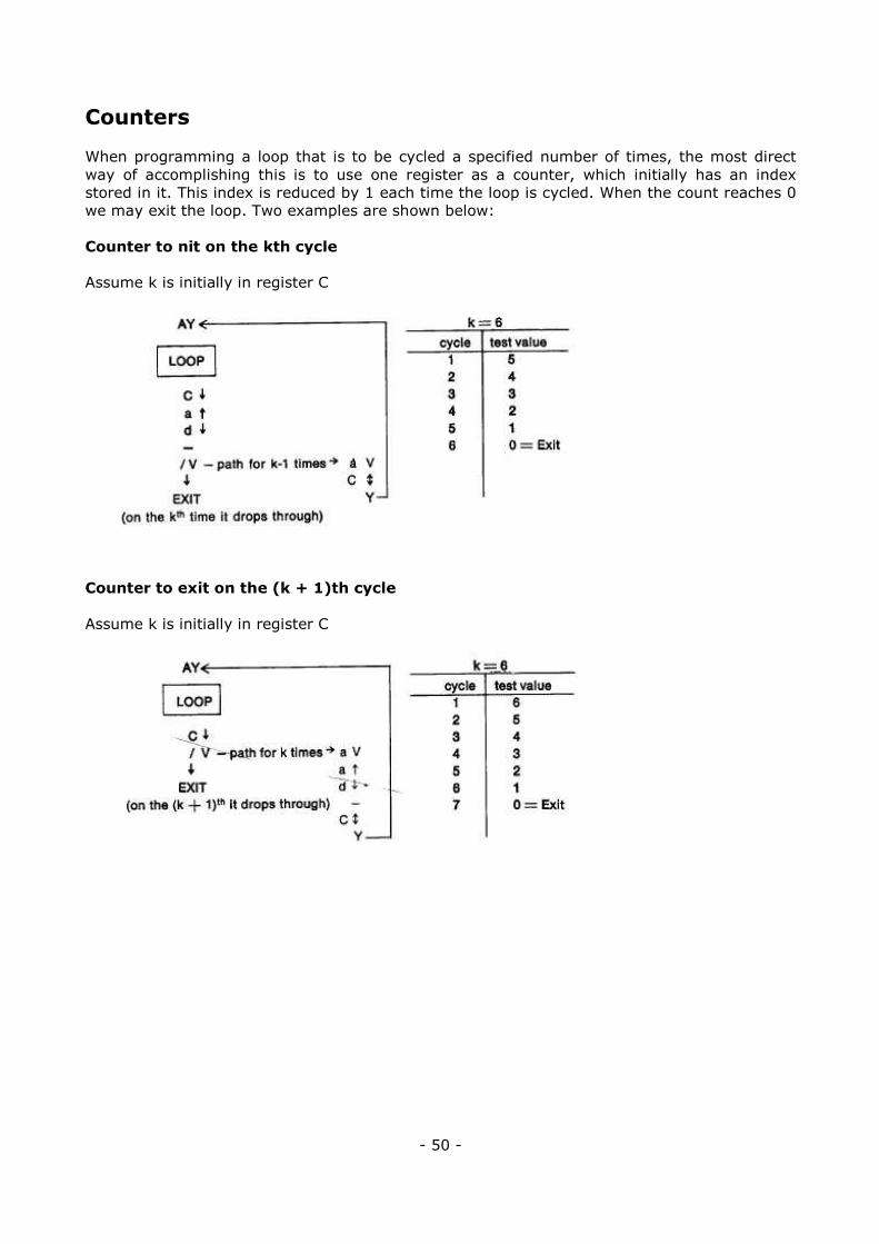
Counters
When programming a loop that is to be cycled a specified number of times, the most direct
way of accomplishing this is to use one register as a counter, which initially has an index
stored in it. This index is reduced by 1 each time the loop is cycled. When the count reaches 0
we may exit the loop. Two examples are shown below:
Counter to nit on the kth cycle
Assume k is initially in register C
Counter to exit on the (k + 1)th cycle
Assume k is initially in register C
- 50 -
Packing a Register
This routine illustrates the concept of "packing" a register. Frequently, it becomes necessary to
store a group of constants in just one register. The following routine exemplifies how each of
the constants might be stored in one register and isolated for manipulation. Let us assume
that we wish to store the constants .453, .281, .397, and .024 all in one register. This can be
accomplished by creating the compound number 453281397.024 and storing it in the D
register. Note that each of the constants must have the same number of digits. The generated
number 1000 will enable us to isolate each of the three digit constants contained within the
compound number.
Set decimal wheel to 3.
A V
D � Bring compound number to A.
A/� Generate the constant 1000 in the M register.
R/S
R S
R S
D �
÷ Divide.
D � Store remaining portion of compound number in D.
R � Isolated number to A.
S Enter some factor.
x Multiply.
A � Print result.
/� Vertical up space.
V Return to AV.
- 51 -
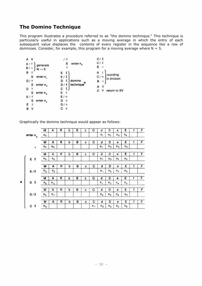
The Domino Technique
This program illustrates a procedure referred to as "the domino technique." This technique is
particularly useful in applications such as a moving average in which the entry of each
subsequent value displaces the contents of every register in the sequence like a row of
dominoes. Consider, for example, this program for a moving average where N = 5. Graphically the domino technique would appear as follows:
- 52 -
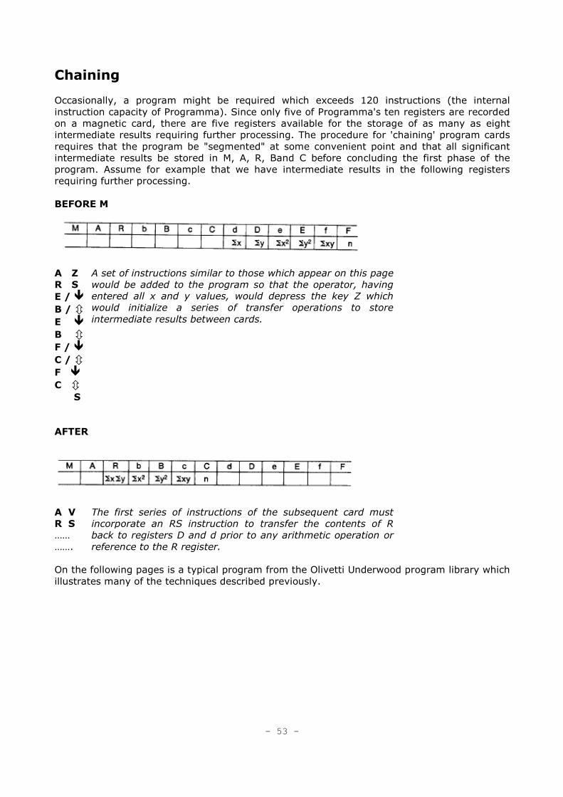
Chaining
Occasionally, a program might be required which exceeds 120 instructions (the internal
instruction capacity of Programma). Since only five of Programma's ten registers are recorded
on a magnetic card, there are five registers available for the storage of as many as eight
intermediate results requiring further processing. The procedure for 'chaining' program cards
requires that the program be "segmented" at some convenient point and that all significant
intermediate results be stored in M, A, R, Band C before concluding the first phase of the
program. Assume for example that we have intermediate results in the following registers
requiring further processing.
BEFORE M
A Z
R S
E / �
B / � E �
B � F / �
C / � F �
C � S
A set of instructions similar to those which appear on this page
would be added to the program so that the operator, having
entered all x and y values, would depress the key Z which
would initialize a series of transfer operations to store
intermediate results between cards.
AFTER
A V
R S
……
…….
The first series of instructions of the subsequent card must
incorporate an RS instruction to transfer the contents of R
back to registers D and d prior to any arithmetic operation or
reference to the R register.
On the following pages is a typical program from the Olivetti Underwood program library which
illustrates many of the techniques described previously.
- 53 -
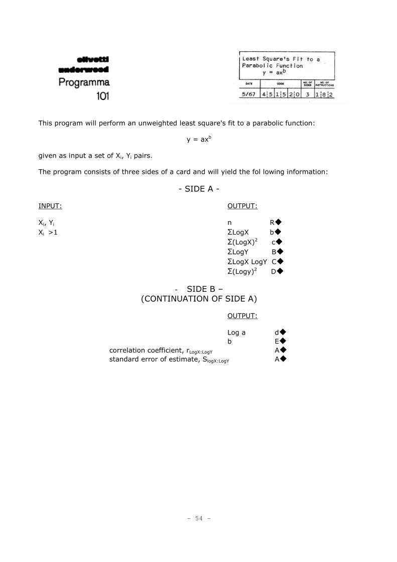
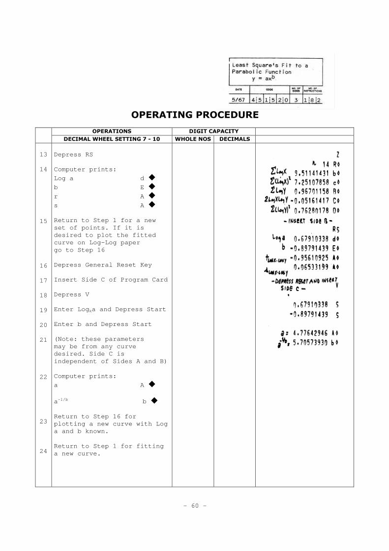
This program will perform an unweighted least square's fit to a parabolic function:
y = axb
given as input a set of Xi, Yi pairs.
The program consists of three sides of a card and will yield the fol lowing information:
- SIDE A -
INPUT: OUTPUT:
Xi, Yi n R�
Xi >1 ΣLogX b�
Σ(LogX)2 c�
ΣLogY B�
ΣLogX LogY C�
Σ(Logy)2 D�
- SIDE B – (CONTINUATION OF SIDE A)
OUTPUT:
Log a d�
b E�
correlation coefficient, rLogX:LogY A�
standard error of estimate, SlogX:LogY A�
- 54 -
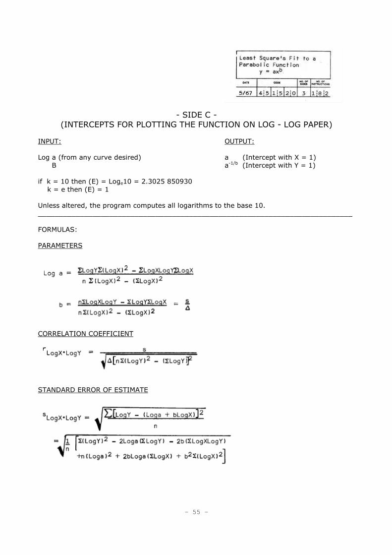
- SIDE C -
(INTERCEPTS FOR PLOTTING THE FUNCTION ON LOG - LOG PAPER)
INPUT: OUTPUT:
Log a (from any curve desired) a (Intercept with X = 1)
B a-1/b (Intercept with Y = 1)
if k = 10 then (E) = Loge10 = 2.3025 850930
k = e then (E) = 1
Unless altered, the program computes all logarithms to the base 10.
___________________________________________________________________________
FORMULAS:
PARAMETERS
CORRELATION COEFFICIENT
STANDARD ERROR OF ESTIMATE
- 55 -
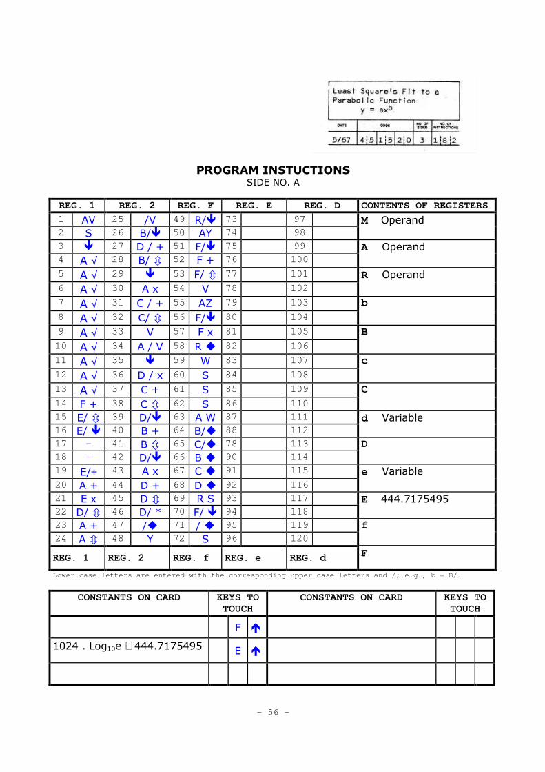
PROGRAM INSTUCTIONS SIDE NO. A
REG. 1 REG. 2 REG. F REG. E REG. D CONTENTS OF REGISTERS
1 AV 25 /V 49 R/� 73 97 2 S 26 B/� 50 AY 74 98
M Operand
3 � 27 D / + 51 F/� 75 99
4 A √ 28 B/ � 52 F + 76 100 A Operand
5 A √ 29 � 53 F/ � 77 101
6 A √ 30 A x 54 V 78 102 R Operand
7 A √ 31 C / + 55 AZ 79 103
8 A √ 32 C/ � 56 F/� 80 104
b
9 A √ 33 V 57 F x 81 105
10 A √ 34 A / V 58 R � 82 106
B
11 A √ 35 � 59 W 83 107
12 A √ 36 D / x 60 S 84 108
c
13 A √ 37 C + 61 S 85 109
14 F + 38 C � 62 S 86 110
C
15 E/ � 39 D/� 63 A W 87 111 16 E/ � 40 B + 64 B/� 88 112
d Variable
17 - 41 B � 65 C/� 78 113 18 - 42 D/� 66 B � 90 114
D
19 E/÷ 43 A x 67 C � 91 115
20 A + 44 D + 68 D � 92 116 e Variable
21 E x 45 D � 69 R S 93 117
22 D/ � 46 D/ * 70 F/ � 94 118 E 444.7175495
23 A + 47 /� 71 / � 95 119
24 A � 48 Y 72 S 96 120 f
REG. 1 REG. 2 REG. f REG. e REG. d F
Lower case letters are entered with the correspondi ng upper case letters and /; e.g., b = B/.
CONSTANTS ON CARD KEYS TO TOUCH
CONSTANTS ON CARD KEYS TO TOUCH
F �
1024 . Log10e ≅ 444.7175495
E �
- 56 -
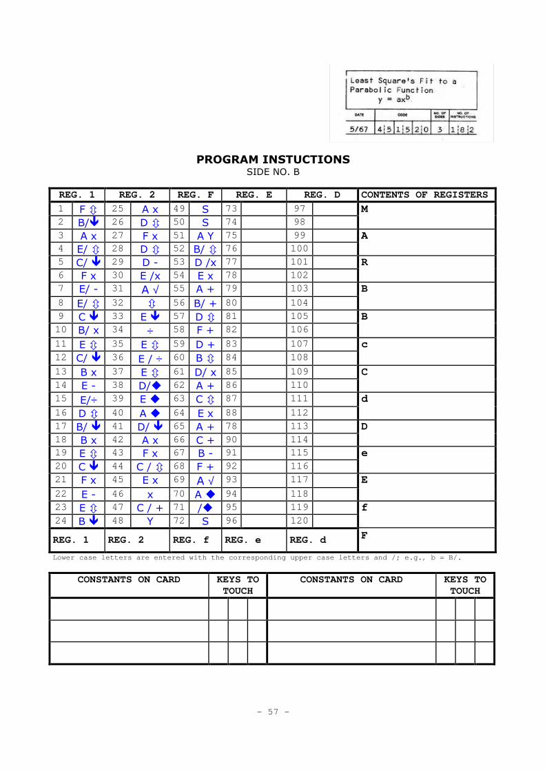
PROGRAM INSTUCTIONS SIDE NO. B
REG. 1 REG. 2 REG. F REG. E REG. D CONTENTS OF REGISTERS
1 F � 25 A x 49 S 73 97 2 B/� 26 D � 50 S 74 98
M
3 A x 27 F x 51 A Y 75 99 4 E/ � 28 D � 52 B/ � 76 100
A
5 C/ � 29 D - 53 D /x 77 101 6 F x 30 E /x 54 E x 78 102
R
7 E/ - 31 A √ 55 A + 79 103
8 E/ � 32 � 56 B/ + 80 104
B
9 C � 33 E � 57 D � 81 105 10 B/ x 34 ÷ 58 F + 82 106
B
11 E � 35 E � 59 D + 83 107
12 C/ � 36 E / ÷ 60 B � 84 108 c
13 B x 37 E � 61 D/ x 85 109
14 E - 38 D/� 62 A + 86 110 C
15 E/÷ 39 E � 63 C � 87 111
16 D � 40 A � 64 E x 88 112
d
17 B/ � 41 D/ � 65 A + 78 113
18 B x 42 A x 66 C + 90 114 D
19 E � 43 F x 67 B - 91 115
20 C � 44 C / � 68 F + 92 116 e
21 F x 45 E x 69 A √ 93 117
22 E - 46 x 70 A � 94 118
E
23 E � 47 C / + 71 /� 95 119
24 B � 48 Y 72 S 96 120 f
REG. 1 REG. 2 REG. f REG. e REG. d F
Lower case letters are entered with the correspondi ng upper case letters and /; e.g., b = B/.
CONSTANTS ON CARD KEYS TO TOUCH
CONSTANTS ON CARD KEYS TO TOUCH
- 57 -
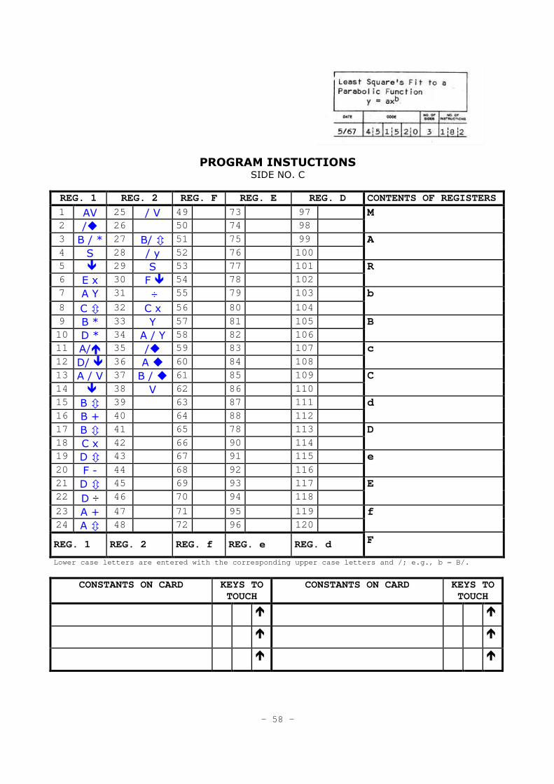
PROGRAM INSTUCTIONS SIDE NO. C
REG. 1 REG. 2 REG. F REG. E REG. D CONTENTS OF REGISTERS
1 AV 25 / V 49 73 97 2 /� 26 50 74 98
M
3 B / * 27 B/ � 51 75 99 4 S 28 / y 52 76 100
A
5 � 29 S 53 77 101 6 E x 30 F � 54 78 102
R
7 A Y 31 ÷ 55 79 103
8 C � 32 C x 56 80 104
b
9 B * 33 Y 57 81 105 10 D * 34 A / Y 58 82 106
B
11 A/� 35 /� 59 83 107
12 D/ � 36 A � 60 84 108 c
13 A / V 37 B / � 61 85 109
14 � 38 V 62 86 110 C
15 B � 39 63 87 111 16 B + 40 64 88 112
d
17 B � 41 65 78 113
18 C x 42 66 90 114 D
19 D � 43 67 91 115
20 F - 44 68 92 116 e
21 D � 45 69 93 117 22 D ÷ 46 70 94 118
E
23 A + 47 71 95 119 24 A � 48 72 96 120
f
REG. 1 REG. 2 REG. f REG. e REG. d F
Lower case letters are entered with the correspondi ng upper case letters and /; e.g., b = B/.
CONSTANTS ON CARD KEYS TO TOUCH
CONSTANTS ON CARD KEYS TO TOUCH
� �
� �
� �
- 58 -
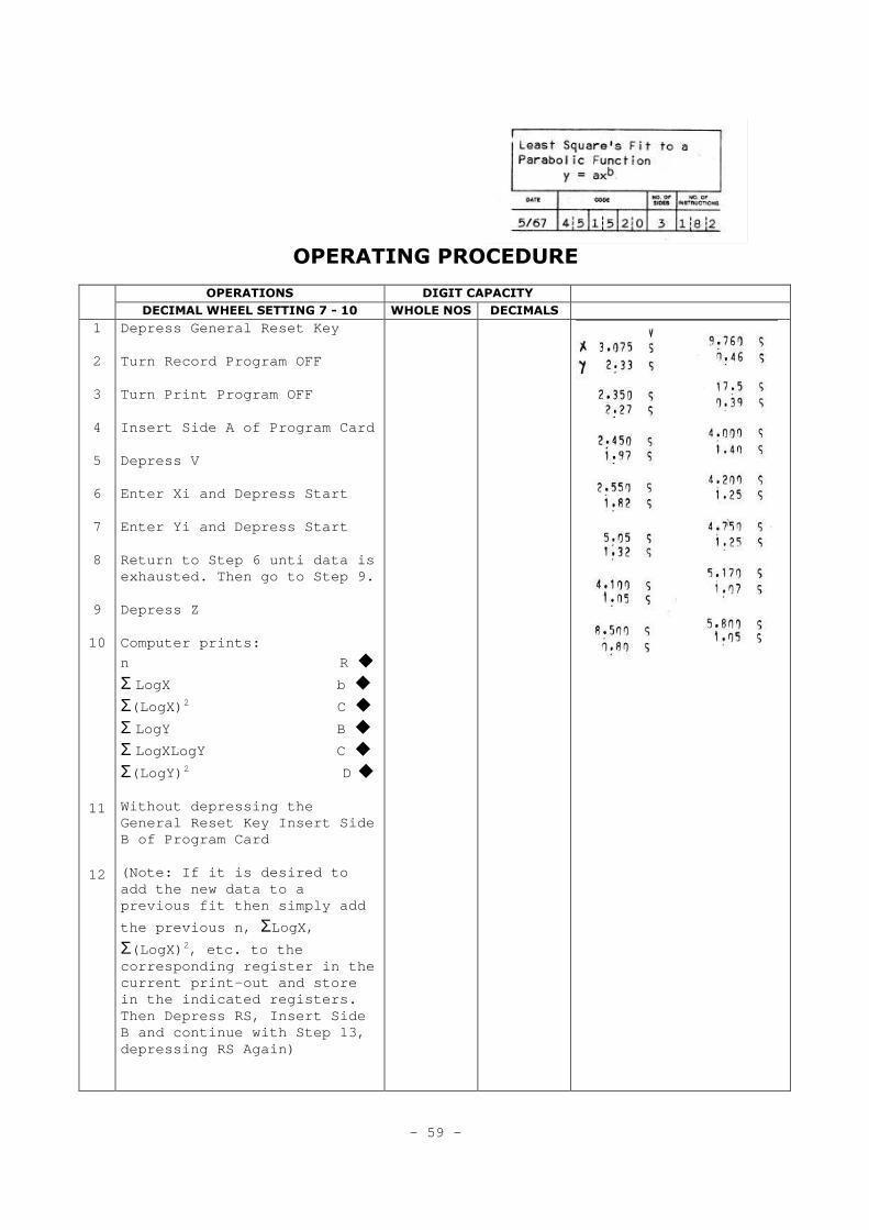
OPERATING PROCEDURE
OPERATIONS DIGIT CAPACITY DECIMAL WHEEL SETTING 7 - 10 WHOLE NOS DECIMALS
1
2
3
4
5
6
7
8
9
10
11
12
Depress General Reset Key Turn Record Program OFF Turn Print Program OFF Insert Side A of Program Card Depress V Enter Xi and Depress Start Enter Yi and Depress Start Return to Step 6 unti data is exhausted. Then go to Step 9. Depress Z Computer prints:
n R �
Σ LogX b �
Σ(LogX) 2 C �
Σ LogY B �
Σ LogXLogY C �
Σ(LogY) 2 D � Without depressing the General Reset Key Insert Side B of Program Card (Note: If it is desired to add the new data to a previous fit then simply add
the previous n, ΣLogX,
Σ(LogX) 2, etc. to the corresponding register in the current print-out and store in the indicated registers. Then Depress RS, Insert Side B and continue with Step 13, depressing RS Again)
- 59 -
OPERATING PROCEDURE
OPERATIONS DIGIT CAPACITY DECIMAL WHEEL SETTING 7 - 10 WHOLE NOS DECIMALS
13
14
15
16
17
18
19
20
21
22
23
24
Depress RS Computer prints:
Log a d �
b E �
r A �
s A � Return to Step 1 for a new set of points. If it is desired to plot the fitted curve on Log-Log paper go to Step 16 Depress General Reset Key Insert Side C of Program Card Depress V Enter Log ka and Depress Start Enter b and Depress Start (Note: these parameters may be from any curve desired. Side C is independent of Sides A and B) Computer prints:
a A �
a–1/b b � Return to Step 16 for plotting a new curve with Log a and b known. Return to Step 1 for fitting a new curve.
- 60 -
Index A Register, 7, 18,20
Absolute Value, 29
Accumulator, 7
Addition, 24
Addresses, Register, 13
Arithmetic Keys, 14
Arithmetic Operations, 23-29
Arithmetic Unit, 6
Automatic Internal Checks,
16, 38
B Register, 7,9
b Register, 7, 9
Branching, 30
C Register, 7, 9
c Register, 7, 9
Capacity
memory, 7
register, 7
printing, 7
Card, Magnetic Program,
9, 11, 36, 38
Card Reader/Recorder, 6
Chaining Program Cards, 53
Clear Entry Key, 13, 36
Clear Key, 14
Clear Operation, 17
Combination Mode, 39
Conditional Jumps, 32
Constants
entry, 34
generation of, 35, 49
in a program, 35
storage of, in registers, 34
Control Unit, 6
Correct Performance Light, 11
Counters, 50
D Register, 7, 9, 21,37
d Register, 7, 9, 21, 37
D-R Exchange, 21, 53
Decimal
handling, 15
point key, 13
wheel, 11, 15
Decimal Part to M, 22, 47, 51
Division, 27
Domino Technique, 52
E Register, 7, 37
e Register, 7, 37
Error
detection, 37, 38
light, 11
Exchange, 20
External Storage, 36, 53
F Register, 7, 9
f Register, 7, 9
From M, 19
General Reset Key, 11
Green Light, 11
Instructions
program, 17-29
to enter, 36
Instruction-Data Storage, 47
Instruction Registers, 8
Jumps, 30
conditional, 32, 33
instructions, 31, 32
unconditional, 31
Keyboard diagram, 12
function of, 11
locked,11
release key, 11
Loops, 30-33
M Register
capacity of, 7
function of, 7,22,23
Magnetic Program Card, 11
Magnetic Card Reader/
Recorder, 6
Manual Mode, 39
Median Register, 7
Memory, 7
Numeric Entry, 13
Numeric Keyboard, 13
On/Off Key, 11
Operating Registers, 7 Operations
arithmetic, 23-29
transfer, 18-22
Packing a Register, 51
Paper Roll, 43
Print Key, 14, 17
Print Program
how to, 37
switch, 11
Printing Unit, 6
Program
creating a, 36, 41
operating a, 38
recording a, 36
Program Mode, 38
R Register, 7, 21, 23, 53
Read/Record D and E, 47
Read/Record Magnetic Card, 6
Read/Write Device, 11
Record Program
how to, 36
switch, 11
Register Address Keys, 13
Register Format, 8, 9 Remainder
in division, 27
in square root, 28
Ribbon Changing, 42
Rounding, 45
Routine Selection Keys, 13
Split Key, 13
function of, 16
Split Registers, 7, 16
Square Root, 28
Start Instruction Key, 13, 17 Stop
Instruction Key, 17 Storage
Registers, 7
Sub-Routine, 30, 37
Subtraction, 25
Tape Advance, 11
Tape Release Lever, 11
Test Instructions, 32, 33
To A, 18
Transfer Keys, 14
Transfer Operations, 18
Unconditional Jumps, 31 Vertical
Space, 17
Zero
division by, 11, 38
testing for, 33
olivetti canada Limited 1390 Don Mills Road, Don Mills, Ontario 447-3351
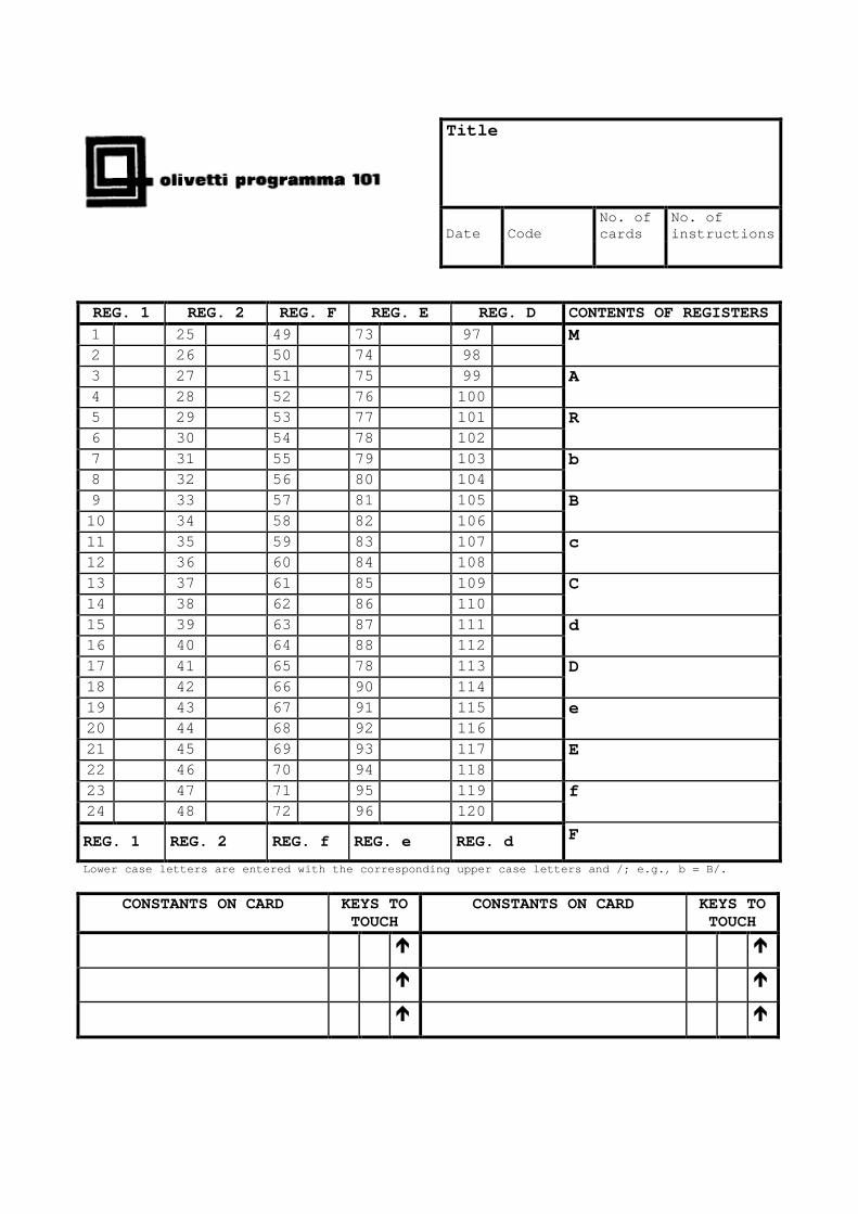
Title
Date Code No. of cards
No. of instructions
REG. 1 REG. 2 REG. F REG. E REG. D CONTENTS OF REGISTERS
1 25 49 73 97 2 26 50 74 98
M
3 27 51 75 99 4 28 52 76 100
A
5 29 53 77 101 6 30 54 78 102
R
7 31 55 79 103 8 32 56 80 104
b
9 33 57 81 105 10 34 58 82 106
B
11 35 59 83 107 12 36 60 84 108
c
13 37 61 85 109 14 38 62 86 110
C
15 39 63 87 111 16 40 64 88 112
d
17 41 65 78 113 18 42 66 90 114
D
19 43 67 91 115 20 44 68 92 116
e
21 45 69 93 117 22 46 70 94 118
E
23 47 71 95 119 24 48 72 96 120
f
REG. 1 REG. 2 REG. f REG. e REG. d F
Lower case letters are entered with the correspondi ng upper case letters and /; e.g., b = B/.
CONSTANTS ON CARD KEYS TO TOUCH
CONSTANTS ON CARD KEYS TO TOUCH
� �
� �
� �