Embed Size (px)
Citation preview
GeneralSpecifications
<<Contents>> <<Index>>
µR20000Recorder
GS 04P02B01-01E
GS 04P02B01-01E©Copyright Aug. 2005(YK)7th Edition June, 2013(KP)
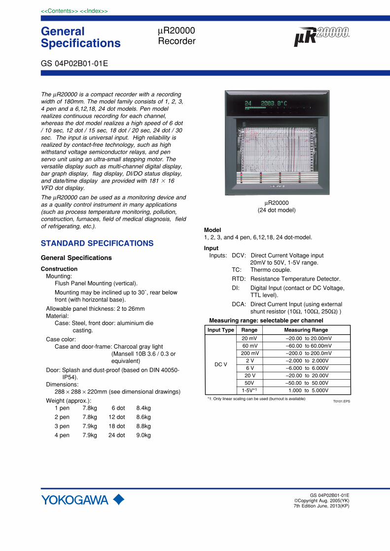
The µR20000 is a compact recorder with a recordingwidth of 180mm. The model family consists of 1, 2, 3,4 pen and a 6,12,18, 24 dot models. Pen modelrealizes continuous recording for each channel,whereas the dot model realizes a high speed of 6 dot/ 10 sec, 12 dot / 15 sec, 18 dot / 20 sec, 24 dot / 30sec. The input is universal input. High reliability isrealized by contact-free technology, such as highwithstand voltage semiconductor relays, and penservo unit using an ultra-small stepping motor. Theversatile display such as multi-channel digital display,bar graph display, flag display, DI/DO status display,and date/time display are provided with 181 16VFD dot display.
The µR20000 can be used as a monitoring device andas a quality control instrument in many applications(such as process temperature monitoring, pollution,construction, furnaces, field of medical diagnosis, fieldof refrigerating, etc.).
STANDARD SPECIFICATIONS
General Specifications
ConstructionMounting:
Flush Panel Mounting (vertical).
Mounting may be inclined up to 30˚, rear belowfront (with horizontal base).
Allowable panel thickness: 2 to 26mmMaterial:
Case: Steel, front door: aluminium die casting.
Case color:Case and door-frame: Charcoal gray light
(Mansell 10B 3.6 / 0.3 orequivalent)
Door: Splash and dust-proof (based on DIN 40050- IP54).Dimensions:
288 × 288 × 220mm (see dimensional drawings)
Weight (approx.):1 pen 7.8kg 6 dot 8.4kg
2 pen 7.8kg 12 dot 8.6kg
3 pen 7.9kg 18 dot 8.8kg
4 pen 7.9kg 24 dot 9.0kg
µR20000(24 dot model)
Model1, 2, 3, and 4 pen, 6,12,18, 24 dot-model.
InputInputs: DCV: Direct Current Voltage input 20mV to 50V, 1-5V range.
TC: Thermo couple.
RTD: Resistance Temperature Detector.
DI: Digital Input (contact or DC Voltage,TTL level).
DCA: Direct Current Input (using externalshunt resistor (10Ω, 100Ω, 250Ω) )
Measuring range: selectable per channel
T0101.EPS
Input Type Range Measuring Range
DC V
20 mV 60 mV 200 mV
2 V 6 V 20 V50V
1-5V*1
–20.00 to 20.00mV–60.00 to 60.00mV–200.0 to 200.0mV–2.000 to 2.000V–6.000 to 6.000V–20.00 to 20.00V
–50.00 to 50.00V 1.000 to 5.000V
*1: Only linear scaling can be used (burnout is available)
2
All Rights Reserved. Copyright © 2005, Yokogawa Electric Corporation GS 04P02B01-01E
<<Contents>> <<Index>>
7th Edition
*2: R, S, B, K, E, J, T, N: IEC584-1(1995), DIN IEC584, JIS C1602-1995*3: W: W-5% Re/W-26% Re(Hoskins Mfg. Co.), ASTM E988*4: L: Fe-CuNi, DIN43710, U: Cu-CuNi, DIN43710*5: WRe: W-3% Re/W-25% Re(Hoskins Mfg. Co.)*6: Pt100: JIS C1604-1997, IEC751-1995, DIN IEC751-1996 JPt100: JIS C1604-1989, JIS C1606-1989 Measuring current: i=1mA T0201.EPS
Input Range Measuring Range ˚C
TC
R*2
S*2
B*2
K*2
E*2
J*2
T*2
N*2
W*3
L*4
U*4
WRe*5
Pt100*6
JPt100*6
DCV input
Contactinput
0.0 to 1760.0˚C 0.0 to 1760.0˚C 0.0 to 1820.0˚C –200.0 to 1370.0˚C –200.0 to 800.0˚C –200.0 to 1100.0˚C –200.0 to 400.0˚C 0.0 to 1300.0˚C 0.0 to 2315.0˚C –200.0 to 900.0˚C –200.0 to 400.0˚C 0.0 to 2400.0˚C –200.0 to 600.0˚C –200.0 to 550.0˚C
Measuring Range ˚F
32 to 3200˚F 32 to 3200˚F 32 to 3308˚F –328 to 2498˚F–328.0 to 1472.0˚F–328.0 to 2012.0˚F–328.0 to 752.0˚F 32 to 2372˚F 32 to 4199˚F–328.0 to 1652.0˚F–328.9 to 752.0˚F 32 to 4352˚F–328.0 to 1112.0˚F–328.0 to 1022.0˚F
OFF: 2.4V less ON: 2.4V or greater
Contact input ON/OFF
RTD*6
DI
Measurement Interval: Pen model: 125ms / channel
Dot printing model: 1s / 6 dot, 2.5s / 12-24 dot 2.5s / 6 dot, 5s / 12 dot, 10s /
18-24 dot (AD integration time is 100ms)
A / D Integration Time:AUTO / FIX selectable
AUTO: 20ms (50Hz) or 16.7ms (60Hz), auto-matically selected depending on thepower supply frequency.
FIX: 20ms (50Hz), 16.7ms (60Hz) or 100ms(50 / 60Hz)*1 can be selected.
*1 100ms integration time: only for dot printing model (not available for 1s / 6 dot measure- ment interval)
TC Burnout:ON / OFF selectable (per channel).
Burnout upscale / downscale selectable (perchannel)
Normal: less than 2kΩ, burnout: more than 10MΩ.
Measuring current: approx. 10µA.
1-5V Burnout: Burnout: less than 0.2V
Filter:Pen model:
Signal damping: ON / OFF selectable per channel
Time constant : 2, 5, 10secDot printing model:
Moving average: ON / OFF selectable per channel
Moving average cycle: 2 to 16
Computation:Differential computation:
Between any two channels, howeverreference channel number must be smallerthan measuring channel number.Available for DCV, TC, and RTD range.Both channels must have same range.
Linear scaling:
Available for DCV, TC , RTD and DI range.
Scaling range: –20000 to 30000
Data display & printout range: –19999 to 30000
Decimal point: User selectable
Unit: User settable, up to 6 characters (alphanumerical & special characters).
Square root:
Available for DCV range.
Scaling range: –20000 to 30000
Data display & printout range: –19999 to 30000
Decimal point: User selectable
Unit: User settable, up to 6 characters (alphanumerical & special characters).
Low level cut off: 0.0 to 5.0% of recording span
Bias addition: –10.0 to 10.0% of recording span
Recording and PrintingRecording Method:
Pen model: Disposable felt pens, Plotter pen
Dot printing model: 6 color wire dot.
Pen Offset Compensation:ON / OFF selectable (Pen model only)
Effective Recording Width: 180mmChart:
Plain-paper Z-fold chart (20m)
Step Response Time (pen):Approx. 1.5s /IEC 61143 method
Recording Period:Pen model:
Continuous for each channel.
Dot printing model*:
Max. 6 channel / 10sec(the shortest record- ing period)
7 to 12 channels / 15sec(the shortest recording period)
13 to 18 channels / 20sec(the shortest recording period)19 to 24 channels / 30sec(the shortest
recording period)25 to 48 channels / 60sec(the shortest
recording period)
* The model with /M1 option includes analog recording of mathematical channel.
AUTO / FIX selectable
AUTO: Analog recording interval is de-pending on the chart speed
June 28, 2013-00
3<<Contents>> <<Index>>
All Rights Reserved. Copyright © 2005, Yokogawa Electric Corporation GS 04P02B01-01E 7th Edition
FIX: Analog recording interval is set to the shortest period
Chart Speed:Pen model: 5 to 12000mm/h (82 increments)
Dot printing model: 1 to 1500mm/h (1mm step)
Chart Speed Change:Speed 1, speed 2 change by remote controlsignals (option)
Chart Speed Accuracy:Within ± 0.1% (for recordings longer than1000mm, related to the grid of the chart paper)
Relation between Chart Speed and Printout:(Pen-model)
5 to 9mm/h10 to 1500mm/h
1600 to 12000mm/h
T0301.EPS
Chart Speed • Periodic Printout
NAAvailable
NA
AvailableAvailable
NA
• Alarm Printout• Message Printout• Chart Speed Change Time Printout
(6,12 dot model)
1 to 9mm/h 10 to 100mm/h 101 to 1500mm/h
T0302.EPS
Chart Speed• PeriodicPrintout
• Channel No. or Tag No.
• Alarm Printout• Message Printout• Chart SpeedChange Time Printout
AvailableAvailable
NA
NAAvailable
NA
AvailableAvailable
NA
(18,24 dot model)
T0302-2.EPS
Chart Speed• Alarm Printout• Message Printout• Chart Speed• Change Time Printout
•Channel No. or Tag No.
• Periodic Printout
1 to 9mm/h 10 to 50mm/h 51 to 1500mm/h
AvailableAvailable
NA
AvailableAvailable
NA
NAAvailable
NA
Relation between chart speed and printing intervals ofperiodic printouts (For AUTO interval setting):(Pen-model)
T0303.EPS
Chart Speed
5 to 9mm/h10 to 18mm/h20 to 36mm/h40 to 72mm/h75 to 135mm/h
150 to 180mm/h200 to 320mm/h360 to 1500mm/h
more than 1600mm/h
Printing Interval ofPeriodic Printout
NAEvery 8 hoursEvery 4 hoursEvery 2 hoursEvery hourEvery 30 minutesEvery 20 minutesEvery 10 minutesNA
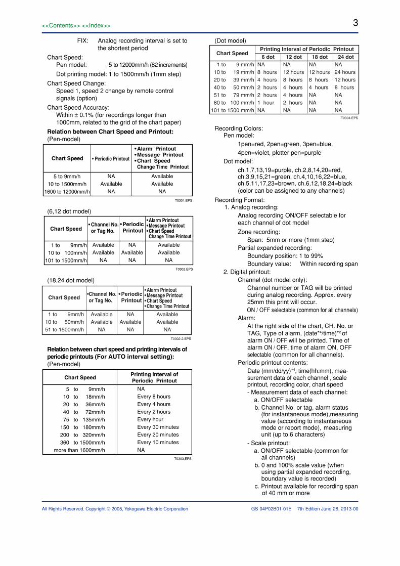
(Dot model)
T0304.EPS
Chart SpeedPrinting Interval of Periodic Printout6 dot 12 dot 18 dot 24 dot
1 to 9 mm/h 10 to 19 mm/h 20 to 39 mm/h 40 to 50 mm/h 51 to 79 mm/h 80 to 100 mm/h101 to 1500 mm/h
NA8 hours4 hours2 hours2 hours1 hourNA
NA12 hours8 hours4 hours4 hours2 hoursNA
NA12 hours8 hours4 hoursNANANA
NA24 hours12 hours8 hoursNANANA
Recording Colors:Pen model:
1pen=red, 2pen=green, 3pen=blue,4pen=violet, plotter pen=purple
Dot model:ch.1,7,13,19=purple, ch.2,8,14,20=red,ch.3,9,15,21=green, ch.4,10,16,22=blue,ch.5,11,17,23=brown, ch.6,12,18,24=black(color can be assigned to any channels)
Recording Format: 1. Analog recording: Analog recording ON/OFF selectable for each channel of dot model
Zone recording:Span: 5mm or more (1mm step)
Partial expanded recording:Boundary position: 1 to 99%Boundary value: Within recording span
2. Digital printout:Channel (dot model only):
Channel number or TAG will be printedduring analog recording. Approx. every25mm this print will occur.
ON / OFF selectable (common for all channels)Alarm:
At the right side of the chart, CH. No. orTAG, Type of alarm, (date*4/time)*2 ofalarm ON / OFF will be printed. Time ofalarm ON / OFF, time of alarm ON, OFFselectable (common for all channels).
Periodic printout contents:Date (mm/dd/yy)*4, time(hh:mm), mea-surement data of each channel , scaleprintout, recording color, chart speed- Measurement data of each channel: a. ON/OFF selectable
b. Channel No. or tag, alarm status (for instantaneous mode),measuring value (according to instantaneous mode or report mode), measuring unit (up to 6 characters)
- Scale printout: a. ON/OFF selectable (common for
all channels) b. 0 and 100% scale value (when
using partial expanded recording, boundary value is recorded)
c. Printout available for recording span of 40 mm or more
June 28, 2013-00
4
All Rights Reserved. Copyright © 2005, Yokogawa Electric Corporation GS 04P02B01-01E
<<Contents>> <<Index>>
7th Edition
- Recording color: Only for pen model (OFF selectable)
- Periodic print interval:
a. Using internal timer b. Standard time 00:00 to 23:00(on the hour)
c. Print interval setting (AUTO/MAN)*5
AUTO: Automatically set as chart speed MAN: 10, 12, 15, 20, 30 minute, 1, 2, 3, 4, 6, 8, 12, 24 hour - Periodic printout mode:
Selectable from Instantaneous value mode / report mode/OFF mode a. Instantaneous value mode:
Measuring value for each channel b. Report mode: Selectable from MIN, MAX, AVE, MIX(MIN/MAX/AVE), SUM, INST Report interval: Same as periodic printout interval c. OFF mode: Periodic printout is not executed.
Message printout:With panel key or remote control option,up to 5 messages can be printed.Contents: (Date*4/time)*1 and message(up to 16 characters).
Record start time:(Date*4/time)*2 will be printed whenrecording starts, ON / OFF selectable.
Chart speed printout:(Date*4/time)*2 when chart speed ischanged will be printed, ON / OFFselectable.
List printout*3:Listings of range and alarm setting, etc.will be printed.
Manual printout*3:With panel key or remote control option,measuring value will be printed.
SET UP List printout*3:Listings of settings in SET UP Mode willbe printed.
*1 Selectable from hh:mm, hh:mm:ss, mm/ddhh:mm, mm/dd hh:mm:ss, mm/dd/yy hh:mm:ss,OFF.
*2 Selectable from hh:mm, hh:mm:ss, mm/ddhh:mm, mm/dd hh:mm:ss, mm/dd/yy hh:mm:ss
*3 During printout trend recording will beinterrupted.
*4 Selectable from mm.dd.yy, yy/mm/dd, mm/dd/yy, dd/mm/yy or dd.mm.yy
*5 According to print settings all the items arenot printed.
DisplayDisplay Method:
VFD 181 × 16 dot matrix
15 display screens can be selected from the any of followings (default display is 6 screens)
- 1 channel digital display*1,*4: AUTO*2/MAN*3
- 2 channel digital display*1,*4: AUTO*2/MAN*3
- 3 channel digital display*4,*5: AUTO*2/MAN*3
- 4 channel digital display*4: Channel No., alarm type, measuring value, with measuring unit (3digits)*6 are displayed
- 6 channel digital display*4: Channel No., alarm type, measuring value are displayed (only for dot model)
- 12 channel digital display*4: measuring value are displayed (only for 12, 18, 24 dot model) - 1 channel digital display*4 + 1 channel bar graph display: AUTO*2/MAN*3
- 1 channel digital display*4 + 4 channel bar graph display (only for pen model): AUTO*2/MAN*3
- 2 channel digital*4 + 2 channel bar graph display: AUTO*2/MAN*3
- 4 channel bar graph display (only for 4 pen model)
- Flag display
- DI/DO display (Available for model with /R1 or /A1, /A2, /A3, /A4, /A5 option)
- Alarm status*1
- Date/time display (mm/dd/yy hh:mm)+Chart speed display*1
- Status display*1
- System display
- Display Off (light out)*1
- Split display: Upper/lower position display
- Tag 1 channel digital display*1,*4: AUTO*2/MAN*3
- Tag 2 channel digital display*4: AUTO*2/MAN*3
- Tag 1 channel digital display*4 + 1 channel bar graph display: AUTO*2/MAN*3
- Tag 1 channel digital display + 4 channel bar graph display*4 (4 pen model only)
- Batch name .... For the model with /BT1 option
Status display: Recording in progress (RECORD)
Shared alarm display (ALARM)
Alarm occurrence No. display (1 to 24)
Chart end indicator (CHART END)....For the model with /F1 option
Computation in progress(MATH).......For the model with /M1 option
Key lock display (KEY LOCK)
*1 The displays can be specified for split display.
*2 AUTO: Channel No., alarm type, measuring value,and measuring unit (6 digits) are displayed in orderof channel No.
For 2 channel digital display + 2 channel bar graphdisplay, the unit display is 3 digits.
No unit display for 3 channel digital display
*3 MAN: The same contents of AUTO for the specified channel are displayed.
*4 Display updated interval can be selected from
June 28, 2013-00
5<<Contents>> <<Index>>
All Rights Reserved. Copyright © 2005, Yokogawa Electric Corporation GS 04P02B01-01E 7th Edition
AUTO / MAN.
AUTO: 1s / 2s / 3s / 4s / 5s
MAN: 2s (pen model), same as measurement interval (dot model)
*5 The display can be specified only for split display.
*6 For computation channel display, the unit display is 2 digits
Power SupplyRated Power Voltage:
100 to 240VAC, automatically selected dependingon the power supply voltage
Usable power voltage ranges:90 to 132, 180 to 264VAC
Rated Power Frequency:50 / 60 Hz, automatically selected
Power Consumption: (approx.)
T0401.EPS
1-4 pen6-24 dot
Maximum
55VA55VA
240VACPower Source
25VA*23VA*
100VACPower Source
17VA*17VA*
* : In Balance
AlarmNumber of alarm levels:
Up to four levels for each channel
Alarm types: High and low, limits, differential high and low limits, high and low rate-of-change limits and delay high and low
Alarm delay time: 1 to 3600s
Interval time of rate-of-change alarms:
The measurement interval times 1 to 15
Display:Alarm value is indicated as a point on the bar graph.
In occurring an alarm: - On bar graph display, a point indicator is flashing.
- On digital display, an alarm type indicator is shown.
- A channel number of occurring alarm is displayed.
- Shared alarm display
Hysteresis:0.0 to 1.0% (0.1% step) of recording span (onlyHigh, Low alarm, common for all channels and alllevels).
Alarm indication when ALARM ACK-key is pressed:Non-hold-type:
Alarm display is not affected when theALARM ACK-key is pressed.
Hold-type:
When alarm occurs, alarm indicator will startflashing. After ALARM ACK-key is pressed,indicator will show status of the alarm.
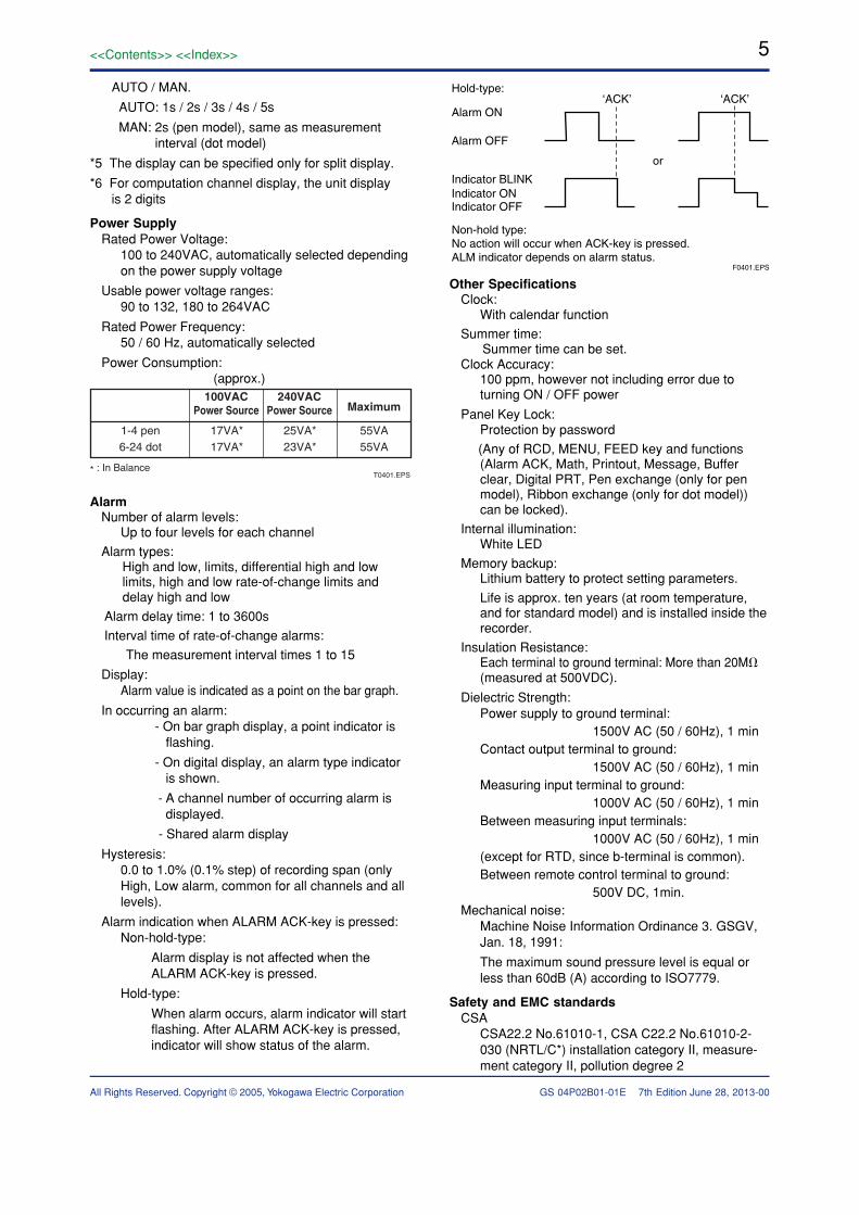
F0401.EPS
Alarm ON
Hold-type:
Alarm OFF
Indicator BLINK
Non-hold type:No action will occur when ACK-key is pressed.ALM indicator depends on alarm status.
or
Indicator ONIndicator OFF
‘ACK’ ‘ACK’
Other SpecificationsClock:
With calendar function
Summer time: Summer time can be set.Clock Accuracy:
100 ppm, however not including error due toturning ON / OFF power
Panel Key Lock:Protection by password
(Any of RCD, MENU, FEED key and functions(Alarm ACK, Math, Printout, Message, Bufferclear, Digital PRT, Pen exchange (only for penmodel), Ribbon exchange (only for dot model))can be locked).
Internal illumination:White LED
Memory backup:Lithium battery to protect setting parameters.
Life is approx. ten years (at room temperature,and for standard model) and is installed inside therecorder.
Insulation Resistance:Each terminal to ground terminal: More than 20M(measured at 500VDC).
Dielectric Strength:Power supply to ground terminal:
1500V AC (50 / 60Hz), 1 minContact output terminal to ground:
1500V AC (50 / 60Hz), 1 minMeasuring input terminal to ground:
1000V AC (50 / 60Hz), 1 minBetween measuring input terminals:
1000V AC (50 / 60Hz), 1 min(except for RTD, since b-terminal is common).Between remote control terminal to ground:
500V DC, 1min.Mechanical noise:
Machine Noise Information Ordinance 3. GSGV,Jan. 18, 1991:
The maximum sound pressure level is equal orless than 60dB (A) according to ISO7779.
Safety and EMC standardsCSA
CSA22.2 No.61010-1, CSA C22.2 No.61010-2-030 (NRTL/C*) installation category II, measure-ment category II, pollution degree 2
June 28, 2013-00
6
All Rights Reserved. Copyright © 2005, Yokogawa Electric Corporation GS 04P02B01-01E
<<Contents>> <<Index>>
7th Edition
* For marking that includes NRTL, a mark with“US” (USA) printed on the right side of the CSAmark, and “C” (Canada) printed on the left sideappears on this instrument.
CEEMC directive:
EN61326-1 compliance, Class A, Table 2(For use in industrial locations)
EN61000-3-2 compliant
EN61000-3-3 compliant
EN55011 compliant, Class A, Group 1
Low voltage directive:
EN61010-1, EN61010-2-030 compliant,installation category II measurementcategory II, pollution degree 2
EMC Regulatory Arrangement in Australia andNew Zealand: EN55011 compliance, Class A, Group 1
Normal Operating ConditionsPower voltage: 90 to 132, 180 to 264VACPower frequency: 50Hz ± 2%, 60Hz ± 2%Ambient temperature: 0 to 50˚CAmbient humidity: 20 to 80% RH (at 5 to 40˚C)Vibration: 10 to 60Hz, 0.2m/s2 or lessShock: Not acceptableMagnetic field: Less than 400A/m (DC and 50, 60Hz)Noise:
Normal Mode (50 / 60Hz):
DCV Peak value including signal mustbe less than 1.2 times themeasuring range.
TC Peak value including signal mustbe less than 1.2 times themeasuring thermal electromotiveforce.
RTD less than 50mV.Common Mode (50 / 60Hz):
Less than 250VAC rms. for the whole rangeMaximum noise voltage between channels
(50 / 60Hz) :250VAC rms or less for pen model and6,12 dot model200VAC rms or less for 18, 24 dot model*When /N2 (3 leg RTD) option is speci-fied,200VAC rms or less for 6 dot,100VAC rms or less for 12, 18, and 24dot model
Operating Position:Frontwards: 0˚ Backwards: Within 30˚ from horizontal
Warm-up Time:Min. 30 minutes after power has been turned ON.
Altitude: 2000m or less
June 28, 2013-00
7<<Contents>> <<Index>>
All Rights Reserved. Copyright © 2005, Yokogawa Electric Corporation GS 04P02B01-01E 7th Edition
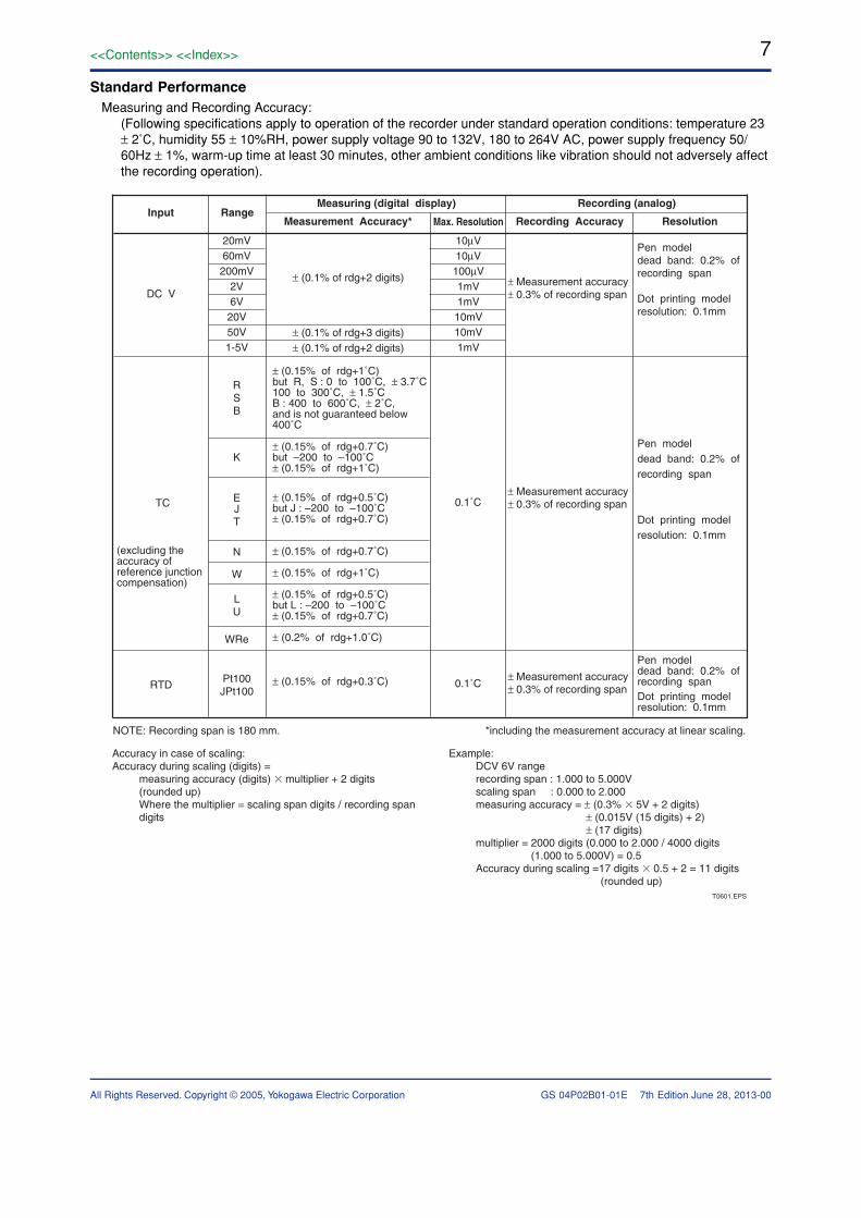
Standard PerformanceMeasuring and Recording Accuracy:
(Following specifications apply to operation of the recorder under standard operation conditions: temperature 23± 2˚C, humidity 55 ± 10%RH, power supply voltage 90 to 132V, 180 to 264V AC, power supply frequency 50/60Hz ± 1%, warm-up time at least 30 minutes, other ambient conditions like vibration should not adversely affectthe recording operation).
DC V
10µV10µV100µV1mV1mV10mV10mV1mV
20mV60mV
200mV2V6V
20V50V1-5V
± (0.1% of rdg+2 digits)
± (0.1% of rdg+3 digits)± (0.1% of rdg+2 digits)
Pen modeldead band: 0.2% of recording span
Dot printing modelresolution: 0.1mm
± Measurement accuracy ± 0.3% of recording span
± Measurement accuracy ± 0.3% of recording span
± Measurement accuracy ± 0.3% of recording span
TC
RTD
RSB
K
E 0.1˚C
0.1˚C
JT
N
W
LU
Pt100JPt100
± (0.15% of rdg+1˚C)but R, S : 0 to 100˚C, ± 3.7˚C100 to 300˚C, ± 1.5˚CB : 400 to 600˚C, ± 2˚C,and is not guaranteed below400˚C
± (0.15% of rdg+0.7˚C)but –200 to –100˚C± (0.15% of rdg+1˚C)
± (0.15% of rdg+0.3˚C)
± (0.15% of rdg+0.5˚C)but J : –200 to –100˚C± (0.15% of rdg+0.7˚C)
± (0.15% of rdg+0.7˚C)
± (0.15% of rdg+1˚C)
± (0.15% of rdg+0.5˚C)but L : –200 to –100˚C± (0.15% of rdg+0.7˚C)
± (0.2% of rdg+1.0˚C)
Pen modeldead band: 0.2% of recording span
Dot printing modelresolution: 0.1mm
Pen modeldead band: 0.2% of recording spanDot printing modelresolution: 0.1mm
(excluding the accuracy of reference junction compensation)
Input RangeMax. ResolutionMeasurement Accuracy*
Measuring (digital display)
ResolutionRecording Accuracy
Recording (analog)
NOTE: Recording span is 180 mm. *including the measurement accuracy at linear scaling.
T0601.EPS
Accuracy in case of scaling:Accuracy during scaling (digits) = measuring accuracy (digits) multiplier + 2 digits (rounded up) Where the multiplier = scaling span digits / recording span digits
Example: DCV 6V range recording span : 1.000 to 5.000V scaling span : 0.000 to 2.000 measuring accuracy = ± (0.3% 5V + 2 digits) ± (0.015V (15 digits) + 2) ± (17 digits) multiplier = 2000 digits (0.000 to 2.000 / 4000 digits (1.000 to 5.000V) = 0.5 Accuracy during scaling = 17 digits 0.5 + 2 = 11 digits (rounded up)
WRe
June 28, 2013-00
8
All Rights Reserved. Copyright © 2005, Yokogawa Electric Corporation GS 04P02B01-01E
<<Contents>> <<Index>>
7th Edition
Maximum Allowable Input Voltage:± 10VDC (cont.) for 200mVDC ranges or less andTC, RTD, DI ranges
± 60VDC (cont.) for 2VDC or more
Reference Junction Compensation:INT / EXT selectable (per channel)
Reference Junction Compensation Accuracy(when measuring 0 ˚C or up):
Type R, S, B, W, WRe: ± 1 ˚C
Type K, J, E, T, N, L, U: ± 0.5 ˚C
Input Resistance:10M or more (TC, 20mV, 60mV, 200mV range)
Approx. 1M (2V range or more).
Input Source Resistance:DCV, TC: 2k or less
RTD: 10 or less / wire (The resistance of allthree wires must be equal)
Input Bias Current:10nA or less (except when burnout is specified).
Maximum Common Mode Voltage:250VAC rms (50 / 60Hz)
Maximum Differential Noise between Channels:250VAC rms (50 / 60Hz) or less for pen modeland 6,12 dot model
200VAC rms (50 / 60Hz) or less for 18, 24 dotmodel
*When /N2 (3 leg RTD) option is specified,
200VAC rms (50 / 60Hz) or less for 6 dot,
100VAC rms (50 / 60Hz) or less for 12, 18, and 24 dot model
Interference between Channels:120dB (Input external resistance 500, thedeviation in the case that 60V is applied toanother channel)
Common Mode Rejection Ratio:120dB (50/60Hz ± 0.1%, 500 imbalancebetween ‘–’ terminal and ground)
Normal Mode Rejection Ratio:40dB (50 / 60Hz ± 0.1%)
Effect of Operating ConditionsEffect of Ambient Temperature:
Effect of ambient temperature variation of 10˚C.
Digital display: Within ± (0.1% of rdg+1 digit)
Recording: Within Digital display ± 0.2% of recording span (excluding RJC error)
Effect of Power Supply:Effect of variation within 90 to 132V or 180 to264VAC in rated power supply voltage:
(50 or 60Hz)
Digital display: Within ± 1 digit
Recording: Within ± 0.1% of recording span
Effect of rated power frequency variation of ± 2Hz
(at 100VAC):
Digital display: Within ± (0.1% of rdg+1 digit)
Recording: Same as digital display
Effect of Magnetic Field:Effect of AC (50 / 60Hz) or DC 400A/m field:
Digital display: Within ± (0.1% of rdg+10 digits)
Recording: Less than ± 0.5% of recording span
Effect of Input Source Resistance:Effect of Input Source Resistance variation of
+1k :
DCV range:
200mV or lower range: Within ± 10 µV
2V or higher range: Within –0.1% of rdg
TC range:
Within ± 10 µV
RTD range:
- Effect of 10 per wire (resistances of threewires must be equal):
Digital display: Within ± (0.1% of rdg+1 digit)
Recording: Within Digital display ± 0.1% of recording span
- Effect of difference of three wires:
Digital display: 0.1˚C per 40 m (approx.) for Pt100 range.
Effect of Operating Position:Digital display: Within ± (0.1% of rdg+1 digit) (within 30˚ backwards)
Recording: Within Digital display ± 0.1% of recording span (within 30˚ backwards)
Vibration:Effect when sine-wave motion of frequency 10 to60Hz and acceleration of 0.2m/s2 is applied to theinstrument in the direction of three axes for twohours:
Digital display: Within ± (0.1% of rdg+1 digit)
Recording: Within Digital display ± 0.1% ofrecording span
Transport and Storage ConditionsNo malfunction will occur under these conditions,however when returning to normal operation condi-tions, calibration might be necessary.Temperature: –25˚C to 60˚CHumidity: 5 to 95% RH (no condensation)Vibration: 10 to 60Hz, 4.9m/s2
Shock: 392m/s2 or less (while beingpacked)
June 28, 2013-00
9<<Contents>> <<Index>>
All Rights Reserved. Copyright © 2005, Yokogawa Electric Corporation GS 04P02B01-01E 7th Edition
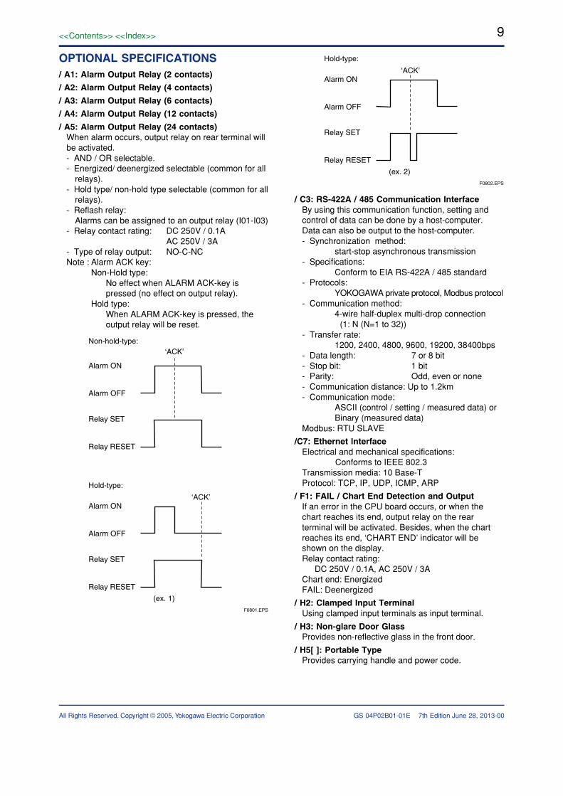
OPTIONAL SPECIFICATIONS/ A1: Alarm Output Relay (2 contacts)
/ A2: Alarm Output Relay (4 contacts)
/ A3: Alarm Output Relay (6 contacts)
/ A4: Alarm Output Relay (12 contacts)
/ A5: Alarm Output Relay (24 contacts)When alarm occurs, output relay on rear terminal willbe activated.- AND / OR selectable.- Energized/ deenergized selectable (common for all
relays).- Hold type/ non-hold type selectable (common for all
relays).- Reflash relay:
Alarms can be assigned to an output relay (I01-I03)- Relay contact rating: DC 250V / 0.1A
AC 250V / 3A- Type of relay output: NO-C-NCNote : Alarm ACK key:
Non-Hold type:No effect when ALARM ACK-key ispressed (no effect on output relay).
Hold type:When ALARM ACK-key is pressed, theoutput relay will be reset.
F0801.EPS
‘ACK’
‘ACK’
(ex. 1)
Alarm ON
Non-hold-type:
Hold-type:
Alarm OFF
Relay SET
Relay RESET
Alarm ON
Alarm OFF
Relay SET
Relay RESET
F0802.EPS
‘ACK’
(ex. 2)
Hold-type:
Alarm ON
Alarm OFF
Relay SET
Relay RESET
/ C3: RS-422A / 485 Communication InterfaceBy using this communication function, setting andcontrol of data can be done by a host-computer.Data can also be output to the host-computer.- Synchronization method:
start-stop asynchronous transmission- Specifications:
Conform to EIA RS-422A / 485 standard- Protocols:
YOKOGAWA private protocol, Modbus protocol- Communication method:
4-wire half-duplex multi-drop connection (1: N (N=1 to 32))- Transfer rate:
1200, 2400, 4800, 9600, 19200, 38400bps- Data length: 7 or 8 bit- Stop bit: 1 bit- Parity: Odd, even or none- Communication distance: Up to 1.2km- Communication mode:
ASCII (control / setting / measured data) orBinary (measured data)
Modbus: RTU SLAVE
/C7: Ethernet lnterfaceElectrical and mechanical specifications: Conforms to IEEE 802.3Transmission media: 10 Base-TProtocol: TCP, IP, UDP, ICMP, ARP
/ F1: FAIL / Chart End Detection and OutputIf an error in the CPU board occurs, or when thechart reaches its end, output relay on the rearterminal will be activated. Besides, when the chartreaches its end, ‘CHART END’ indicator will beshown on the display.Relay contact rating:
DC 250V / 0.1A, AC 250V / 3AChart end: EnergizedFAIL: Deenergized
/ H2: Clamped Input TerminalUsing clamped input terminals as input terminal.
/ H3: Non-glare Door GlassProvides non-reflective glass in the front door.
/ H5[ ]: Portable TypeProvides carrying handle and power code.
June 28, 2013-00
10
All Rights Reserved. Copyright © 2005, Yokogawa Electric Corporation GS 04P02B01-01E
<<Contents>> <<Index>>
7th Edition
/ M1: Mathematical Functions - Computation channel recording
Pen model: Measurement and computation channel can be assigned to 1-4pen.
Dot model: ON/OFF selectable for each channel
Zone recording
Partial expanded recording
- Alarm for computation channel
Number of levels: Up to four levels for every channel (High and low limits, delay High and low)
- Number of computation channel: 8 (pen model)
24 (dot model)
- Computation expression: Up to 120 characters can be used
- Types:
Four arithmetic operations, square root,
absolute, common logarithm, exponential,
power, relational operations (>, , <, , ,),
logic operations (AND, OR, NOT, XOR)
- Constant*: Up to 30 constants can be used
- Number of communication digital input*:
Pen model: 8
Dot model: 24
- Remote input*:Up to 5 remote inputs status(I/O) can be used in computation expression
* It cannot be used in statistical computation expression.
Statistical computation The following computation can be executed for the specified internal timer
- Types of statistics: MAX, MIN, AVE, SUM, MAX- MIN (Totalization)
- Type of interval timer: 3 type
Timer types: Interval of periodic printout, absolute time, relative time
/ N1: Cu10, Cu25 RTD inputThis option allows Cu10 and Cu25 RTD inputs to beadded to the standard input types.
Cu10, Cu25 Measurement Range
T0902.EPS
Input Type
Cu10(GE)Cu10(L&N)Cu10(WEED)Cu10(BAILEY)Cu10 : α = 0.00392 at 20˚CCu10 : α = 0.00393 at 20˚CCu25*: α = 0.00425 at 0˚C
Measurement Range
–200.0 to 300.0˚C(–328.0 to 572.0˚F)RTD
* Measuring current i = 1mA
Measurement / Recording Accuracy
T1001.EPS
Input Type
Cu10(GE)Cu10(L&N)Cu10(WEED)Cu10(BAILEY)Cu10 : α = 0.00392 at 20˚CCu10 : α = 0.00393 at 20˚C
Cu25 : α = 0.00425 at 0˚C
Recording Accuracy
± Measurement accuracy ± 0.3% of recording span
MeasurementAccuracy
± (0.4% of rdg + 1.0˚C)
± (0.3% of rdg + 0.8˚C)
/ N2: 3 Leg Isolated RTD InputA, B, b legs are isolated input type
/N3: Expansion InputsThis option allows 14 types inputs such as Pt50,PR40-20, PLATINEL inputs to be supported besidesthe standard input types.
/N3 Measurement Range
T1002.EPS
Input Measuring Range
TC
0.0 to 1900.0˚C 0.0 to 1400.0˚C 0.0 to 1310.0˚C 0.0 to 2400.0˚C 0.0 to 1300.0˚C 0.0 to 300.0K–200.0 to 550.0˚C –200.0 to 600.0˚C–200.0 to 250.0˚C –60.0 to 180.0˚C –70.0 to 200.0˚C 0.0 to 300.0K –50.0 to 150.0˚C –50.0 to 150.0˚C
32 to 3452˚F 32 to 2552˚F 32 to 2390˚F 32 to 4352˚F 32 to 2372˚F
— –328.0 to 1022.0˚F –328.0 to 1112.0˚F –328.0 to 482.0˚F –76.0 to 356.0˚F –94.0 to 392.0˚F
— –58.0 to 302.0˚F –58.0 to 302.0˚F
RTD(Measuring contact i=1mA)
PR40-20 PLATINEL
NiNiMoW/WRe26
Type N(AWG14)Kp vs Au7Fe
Pt25Pt50
Ni100(SAMA)Ni100(DIN)
Ni120J263*BCu53
Cu100*1
*1: Cu100: α = 0.00425 at 0˚C
Measurement / Recording Accuracy
T1003.EPS
Input Recording Accuracy
± Measurement accuracy ± 0.3% of recording span
MeasuringAccuracy
Not guaranteed± (0.9% of rdg+3.2˚C)± (0.9% of rdg+1.3˚C)± (0.9% of rdg+0.4˚C)± (0.25% of rdg+2.3˚C)± (0.25% of rdg+0.7˚C)within ± 15.0˚C± (0.2% of rdg+2.0˚C)± (0.2% of rdg+1.3˚C)± 4.5K± 2.5K± (0.15% of rdg+0.6˚C)± (0.3% of rdg+0.6˚C)
± (0.15% of rdg+0.4˚C)
± 3.0K± 1.0K± (0.15% of rdg+0.8˚C)± (0.2% of rdg+1.0˚C)
PR40-20*1 0 to450˚C 450 to 750˚C 750 to 1100˚C 1100 to 1900˚CPLATINELNiNiMoW/WRe26 0 to 400˚C 400 to 2400˚CType N(AWG14)Kp vs Au7Fe 0 to 20K 20 to 300KPt25Pt50Ni100(SAMA)Ni100(DIN)Ni120J263*B 0 to 40K 40 to 300KCu53Cu100
*1: PR40-20 : No reference junction compensation ( 0˚C fix)
June 28, 2013-00
11<<Contents>> <<Index>>
All Rights Reserved. Copyright © 2005, Yokogawa Electric Corporation GS 04P02B01-01E 7th Edition
/ P1 : 24VDC/AC Power SupplyRated power supply: 24VDC/ACAllowable power supply voltage range:
21.6 to 26.4 VDC/ACDielectric strength:
Power supply to ground terminal: 1000VAC Power Consumption: (approx.)
T1004.EPS
Supply Voltage
24VDC24VAC (50/60Hz)
Max.
9VA*17VA*
1-4 pen
10VA*18VA*
6 dot
* In Balance
35VA45VA
/ R1: Remote Control5 are selectable from the below mentioned remotecontrols.
Number of settings SignalRecording start / stop 1 edgeChart speed change 1 levelMessage printout start*1 5 triggerManual printout start 1 triggerAlarm ACK 1 triggerTime adjustment 1 trigger (Adjusting the time to a preset time)Computation start / stop*2 1 edgeComputation reset*2 1 triggerBatch comment switch*3 1 levelPriorty remote recording*3 1 level
*1 Up to 5 messages can be set*2 / M1 option is necessary*3 Available for the model with /BT1 option
/ CC1: Calibration correctionCorrects the mesurement value of each channelusing segment linearizer approximation.Number of segment points: 2 to 16Setting method: Bias, Abolute valueTarget Channel: Measurement channelTarget range:
Input range (DCV, TC, RTD)Linear scaling range (DCV, TC, RTD, 1-5V)But, DI, Differentioal computation and square rootare not included.
/BT1: Header printoutBatch name, comment, time, chart speed are printedin record Start/Stop.Message printout including measured value/compu-tation value is available.- Printout contents:
Batch name: Batch number-Lot number (ON/OFF selectable)
Batch number: Up to 26 characters can be setLot number: 4 digits/6 digits/OFF selectable
Start/Stop comment: Up to 64 characters 5 lines can be set
Start/Stop time: ON/OFF selectable Start/Stop chart speed: ON/OFF selectable
- Message printout: Printout contents (message format: ON/OFF selectable)
ON: any (date/time, message (up to 16characters), measured value) can beselected (up to 69 characters)
OFF: Date/time + message (up to 16 charac-ters)
APPLICATION SOFTWAREWith Ethernet (/C7), RS-422A/485 (/C3), or Interfaceunit, µR20000 setting can be configured.
• RXA10 Configuration Software*System requirements
OS: Windows 2000 SP4 / Windows XPHome Edition SP3 / Windows XPProfessional SP3 (excluding WindowsXP Professional x64 Edition) / WindowsVista Home Premium SP1, SP2(excluding the 64-bit edition) / WindowsVista Business SP1, SP2 (excluding the64-bit edition) / Windows 7 HomePremium (32-bit and 64-bit editions) /Windows 7 Professional (32-bit and 64-bit editions)
Processor:When Using Windows 2000 or Windows XP
CPU: Pentium III 600 MHz or higher (800 MHzPentium III or higher recommended).
Memory: 512 MB or more.Hard disk: Free disk space of 10 MB or more.
When Using Windows VistaCPU: Pentium IV, 3.0 GHz or fasterMemory: 1 GB or more.Hard disk: Free disk space of 200 MB or more.
When Using Windows 732-bit edition:CPU: Intel Pentium IV, 3.0 GHz or faster x64
or x86 processorMemory: 2 GB or more.64-bit edition:CPU: Intel x64 processor that is equivalent to
Intel Pentium IV, 3.0 GHz or fasterMemory: 2 GB or more.Hard disk: Free disk space of 200 MB or more.
CD-ROM drive: A CD-ROM drive supported by theOS.
Mouse: A mouse supported by the OS.Monitor:When Using Windows 2000 or Windows XP
A monitor supported by the OS of 1024 768 dpior higher and 32K colors or more (64 Kcolors recommended).
When Using Windows Vista or Windows 7A monitor supported by the OS of 1024 768 dpi
or higher and 65,536 colors or more.
June 28, 2013-00
12
All Rights Reserved. Copyright © 2005, Yokogawa Electric Corporation GS 04P02B01-01E
<<Contents>> <<Index>>
7th Edition
Main functions (as a package):Configuration software:
Configuration via communication:Configures the station, excluding thecommunication setting, or sets it in setmode.
* Note This software applies for µR20000 from R2.01 version.
June 28, 2013-00
11–––––211
6, 12, 18, 24 dot
1–11111211
4 pen
1–111–1211
3 pen
1–11––1211
2 pen
1–1–––1211
RedGreenBlueVioletPurple
Z-fold chart6 color ribbon cassette
Disposable felt-pen cartridge
Plotter penMounting bracketsInstruction Manual (CD-ROM)Operation Manual
1 penName
T1101.EPS
STANDARD ACCESSORIES
OSDescription
Windows 2000/XP/Vista/7
Windows 2000/XP/Vista/7
RXA10 Configuration software*RXA10 Configuration software* (With interface unit)
RXA10-01
RXA10-02
ModelCode
Model CodesModelcode
Suffix code
Option code
Description
437101437102437103437104437106437112437118437124Language -2Option
µR20000 1 pen recorderµR20000 2 pen recorderµR20000 3 pen recorderµR20000 4 pen recorderµR20000 6 dot recorderµR20000 12 dot recorderµR20000 18 dot recorderµR20000 24 dot recorder
*1: only one of /A1, /A2, /A3, /A4, /A5 can be selected *2: /A4 and /F1 can not be specified together for pen model *3: /A5 and /F1 can not be specified together *4: /A5 can be specified only for dot model *5: /C3 and /C7 can not be specified together *6: /H2 and /N2 can not be specified together *7: /N2 can be specified only for dot model *8: 14 types inputs: Pt50 RTD, PR40-20, PLTINEL TC etc.*9: /H5[ ] and /P1 can not be specified together*10: /H5[ ] (D-power cord UL, CSA, st'd, F-Power cord VDE st'd,
R-Power cord SAA st'd, J-Power cord BS st'd, H-Power cord GB st'd)
*11: Available from firmware version R1.21
* Configuration software can be used for both µR10000 / µR20000. This software applies for µR20000 from R2.01 version. This software applies for Windows Vista from R3.03 version. This software applies for Windows7 from R3.04.01 version.
/A1/A2/A3/A4/A5
/C3/C7
/F1/H2/H3
/M1/N1/N2/N3
/R1
English/German*11/French*11, degF & DSTAlarm output relay (2 contacts) *1
Alarm output relay (4 contacts) *1
Alarm output relay (6 contacts) *1
Alarm output relay (12 contacts) *1*2
Alarm output relay (24 contacts) *1*3*4
/BT1 Header printoutRS-422A/485 Interface *5
Ethernet communication interface *5
FAIL / Chart end detection and output *2*3
Clamped input terminal *6
Non-glare door glass/H5[ ]*10 Portable Type *9
Mathematical ComputationsCu10, Cu25 RTD input 3 leg RTD (dot printing model only) *6*7
Expansion inputs *8
/P1 24VDC/AC power supply *9
Remote controls (5 contacts)
/CC1 Calibration Correction
• Interface unit (attached with RXA10configuration software)
Method of power supply: Power supply fromµR20000
Connector type: D-Sub 9-pin plug (male)Electrical and mechanical specifications: Conforms to EIA-574 (9-pin EIA-232
(RS232))RS422A/485 communication interface (/C3) andinterface unit cannot work together.
13<<Contents>> <<Index>>
All Rights Reserved. Copyright © 2005, Yokogawa Electric Corporation GS 04P02B01-01E 7th Edition June 28, 2013-00
Name
Z-fold chart6 color ribbon cassette
Disposable felt-pen cartridge
Plotter penMounting brackets
Shunt resistor
SPARES/OPTIONAL ACCESSORIES
RedGreenBlueVioletPurple
SpecificationModel Code(Parts No.)
(for screw input terminal)
(for clamped input terminal)
B9573ANB9906JAB9902AMB9902ANB9902APB9902AQB9902ARB9900BX4159 204159 214159 224389 204389 21
4389 22
10 (sales unit)1 (sales unit)1 (sales unit, 3 pieces/unit)1 (sales unit, 3 pieces/unit) 1 (sales unit, 3 pieces/unit) 1 (sales unit, 3 pieces/unit) 1 (sales unit, 3 pieces/unit) 2 (sales unit)250Ω ± 0.1%100Ω ± 0.1%10Ω ± 0.1%250Ω ± 0.1%100Ω ± 0.1%10Ω ± 0.1%
T1102.EPS
• Microsoft, MS and Windows are registered trademarks of Microsoft Corporation USA.• Pentium are registered trademarks of Intel Corporation.• Ethernet is a registered trademark of XEROX Corporation.• Modbus is a registered trademark of AEG Schneider• Other company and/or product names are registered trade mark of their manufactures.
14
All Rights Reserved. Copyright © 2005, Yokogawa Electric Corporation GS 04P02B01-01E
<<Contents>> <<Index>>
7th Edition
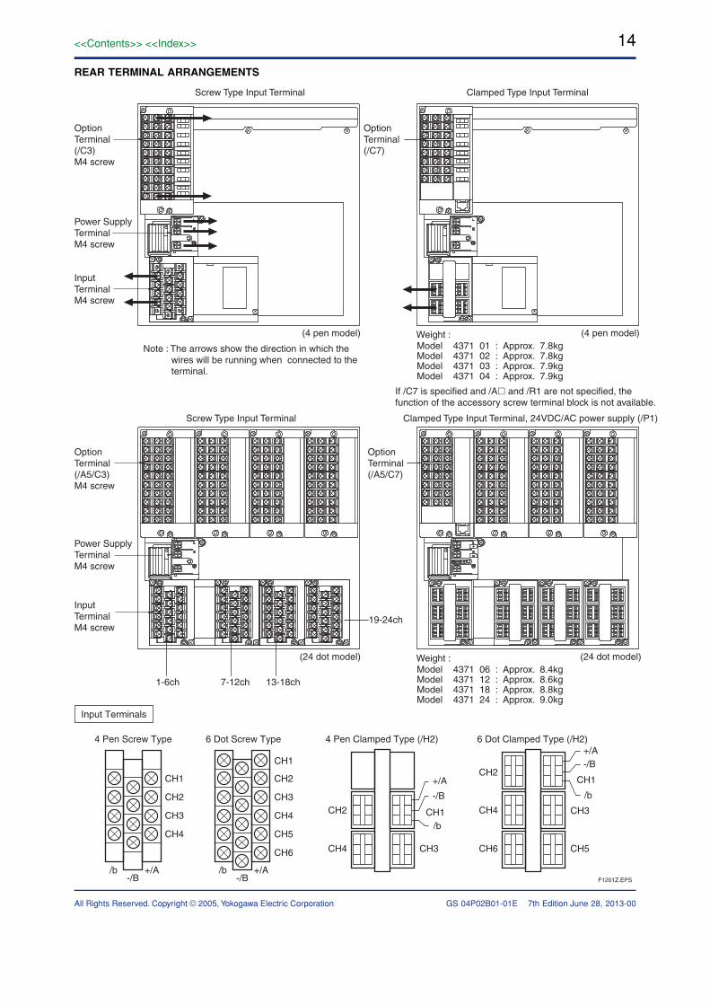
REAR TERMINAL ARRANGEMENTS
Input Terminals
4 Pen Screw Type
CH1
CH2
CH3
CH4
/b +/A-/B
6 Dot Screw Type 4 Pen Clamped Type (/H2)
CH2
CH1
CH3CH2
CH4 CH3
CH1
+/A
-/B
/b
6 Dot Clamped Type (/H2)
CH4
CH2
CH6 CH5
CH3
CH1
+/A-/B
/b
CH4
CH5
CH6
/b +/A-/B F1201Z.EPS
Note : The arrows show the direction in which the wires will be running when connected to the terminal.
(4 pen model)
InputTerminalM4 screw
Power SupplyTerminalM4 screw
OptionTerminal(/C3)M4 screw
Screw Type Input Terminal
(4 pen model)
Clamped Type Input Terminal
Weight :Model 4371 01 : Approx. 7.8kgModel 4371 02 : Approx. 7.8kgModel 4371 03 : Approx. 7.9kgModel 4371 04 : Approx. 7.9kg
OptionTerminal(/C7)
(24 dot model) (24 dot model)Weight :Model 4371 06 : Approx. 8.4kgModel 4371 12 : Approx. 8.6kgModel 4371 18 : Approx. 8.8kgModel 4371 24 : Approx. 9.0kg
Screw Type Input Terminal Clamped Type Input Terminal, 24VDC/AC power supply (/P1)
If /C7 is specified and /A and /R1 are not specified, the function of the accessory screw terminal block is not available.
InputTerminalM4 screw
1-6ch 7-12ch 13-18ch
19-24ch
Power SupplyTerminalM4 screw
OptionTerminal(/A5/C3)M4 screw
OptionTerminal(/A5/C7)
June 28, 2013-00
15<<Contents>> <<Index>>
All Rights Reserved. Copyright © 2005, Yokogawa Electric Corporation GS 04P02B01-01E 7th Edition June 28, 2013-00
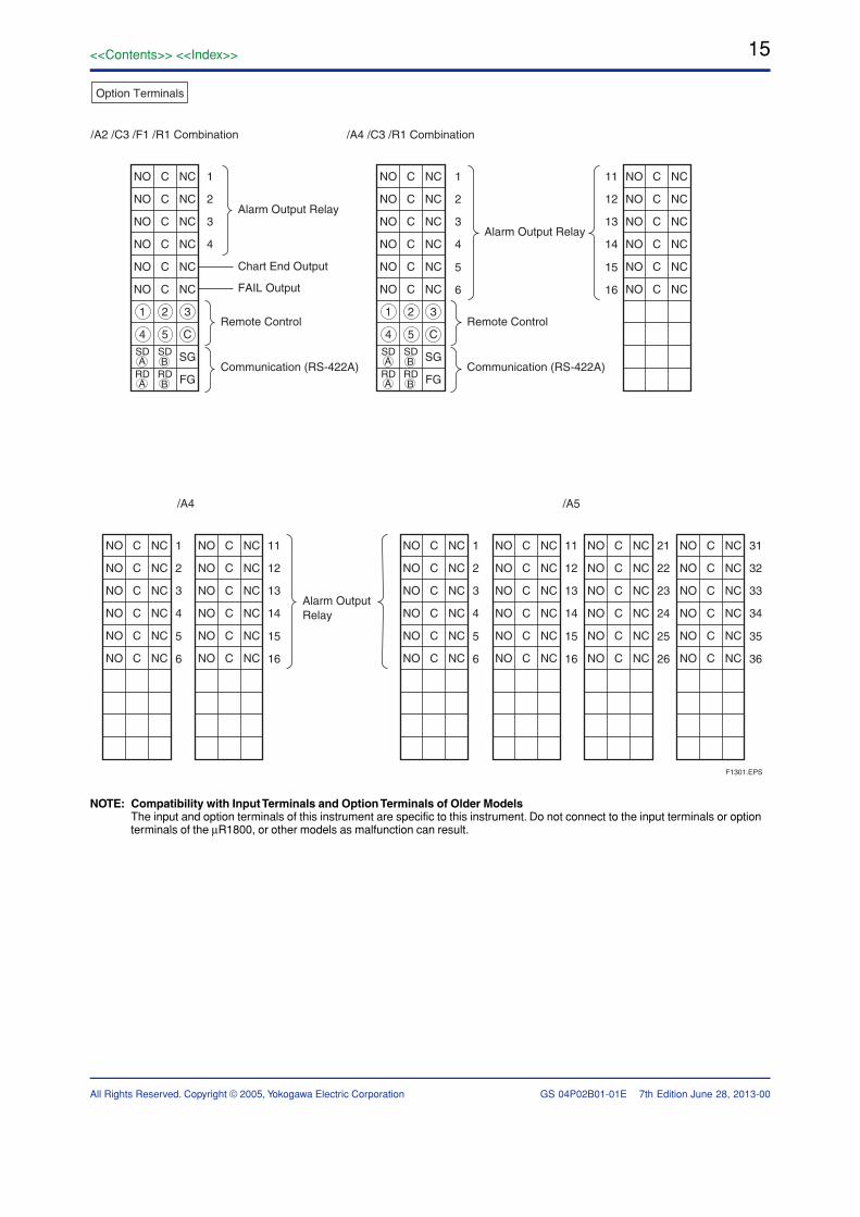
Option Terminals
NO C NC
NO C NC
NO C NC
NO C NC
1
2
3
4
1
2
3
4
5
6
1
2
3
4
5
6
11
12
13
14
15
16
NO C NC
NO C NC
1 2 3
4 5 CSD SD SG
RD RD FG
A B
A B
Alarm Output Relay
Remote Control
Communication (RS-422A)
Alarm Output Relay
Alarm Output Relay
Remote Control
Communication (RS-422A)
Chart End Output
FAIL Output
/A2 /C3 /F1 /R1 Combination
/A4 /A5
NO C NC
NO C NC
NO C NC
NO C NC
NO C NC
NO C NC
1 2 3
4 5 C
SD SD SG
RD RD FG
A B
A B
NO C NC
NO C NC
NO C NC
NO C NC
NO C NC
NO C NC
NO C NC
NO C NC
NO C NC
NO C NC
NO C NC
NO C NC
11
12
13
14
15
16
NO C NC
NO C NC
NO C NC
NO C NC
NO C NC
NO C NC
1
2
3
4
5
6
NO C NC
NO C NC
NO C NC
NO C NC
NO C NC
NO C NC
11
12
13
14
15
16
NO C NC
NO C NC
NO C NC
NO C NC
NO C NC
NO C NC
21
22
23
24
25
26
NO C NC
NO C NC
NO C NC
NO C NC
NO C NC
NO C NC
31
32
33
34
35
36
NO C NC
NO C NC
NO C NC
NO C NC
NO C NC
NO C NC
/A4 /C3 /R1 Combination
F1301.EPS
NOTE: Compatibility with Input Terminals and Option Terminals of Older ModelsThe input and option terminals of this instrument are specific to this instrument. Do not connect to the input terminals or optionterminals of the µR1800, or other models as malfunction can result.
16
All Rights Reserved. Copyright © 2005, Yokogawa Electric Corporation GS 04P02B01-01E
<<Contents>> <<Index>>
7th Edition
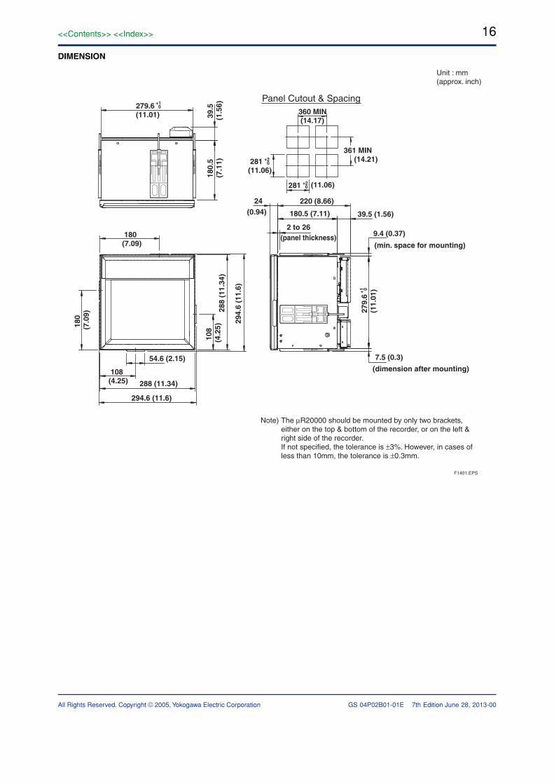
DIMENSION
Note) The µR20000 should be mounted by only two brackets, either on the top & bottom of the recorder, or on the left & right side of the recorder. If not specified, the tolerance is ±3%. However, in cases of less than 10mm, the tolerance is ±0.3mm.
Unit : mm(approx. inch)
Panel Cutout & Spacing360 MIN (14.17)
281(11.06)
180(7.09)
108(4.25)
180
(7.0
9)
108
(4.2
5)
(11.06)
(0.94)
+2 0
279.
6(1
1.01
)+1 0
281 +2 0
361 MIN (14.21)
54.6 (2.15)
288 (11.34)
294.6 (11.6)
288
(11.
34)
294.
6 (1
1.6)
220 (8.66)
180.5 (7.11) 39.5 (1.56)
9.4 (0.37)2 to 26
(panel thickness)(min. space for mounting)
7.5 (0.3)
(dimension after mounting)
24
F1401.EPS
39.
5(1
.56)
180.
5(7
.11)
279.6(11.01)
+1 0
June 28, 2013-00
17<<Contents>> <<Index>>
All Rights Reserved. Copyright © 2005, Yokogawa Electric CorporationSubject to change without notice.
GS 04P02B01-01E 7th Edition
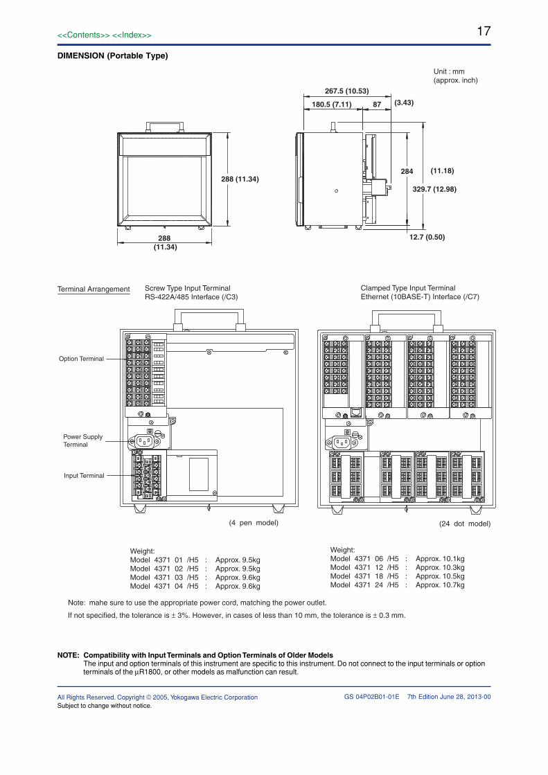
DIMENSION (Portable Type)
Unit : mm(approx. inch)
267.5 (10.53)
Terminal Arrangement
Weight:Model 4371 01 /H5 : Approx. 9.5kgModel 4371 02 /H5 : Approx. 9.5kgModel 4371 03 /H5 : Approx. 9.6kgModel 4371 04 /H5 : Approx. 9.6kg
Weight:Model 4371 06 /H5 : Approx. 10.1kgModel 4371 12 /H5 : Approx. 10.3kgModel 4371 18 /H5 : Approx. 10.5kgModel 4371 24 /H5 : Approx. 10.7kg
Note: mahe sure to use the appropriate power cord, matching the power outlet.
Screw Type Input TerminalRS-422A/485 Interface (/C3)
180.5 (7.11) 87 (3.43)
284 (11.18)
329.7 (12.98)
12.7 (0.50)
288 (11.34)
288 (11.34)
Clamped Type Input TerminalEthernet (10BASE-T) Interface (/C7)
Option Terminal
Power SupplyTerminal
Input Terminal
(4 pen model) (24 dot model)
If not specified, the tolerance is ± 3%. However, in cases of less than 10 mm, the tolerance is ± 0.3 mm.
June 28, 2013-00
NOTE: Compatibility with Input Terminals and Option Terminals of Older ModelsThe input and option terminals of this instrument are specific to this instrument. Do not connect to the input terminals or optionterminals of the µR1800, or other models as malfunction can result.


![Fountain Pen Care - Lanier Pens · 2020. 7. 8. · Fountain Pen Care Taking care of your fountain pen[s] is not very difficult. A pen loves to be used! Ink in a fountain pen will](https://img.pdfslide.us/doc/110x75/60c85572981a226ffa2dcb6d/fountain-pen-care-lanier-pens-2020-7-8-fountain-pen-care-taking-care-of-your.jpg)