Embed Size (px)
Citation preview
WP.AFD.05 July 22, 2009
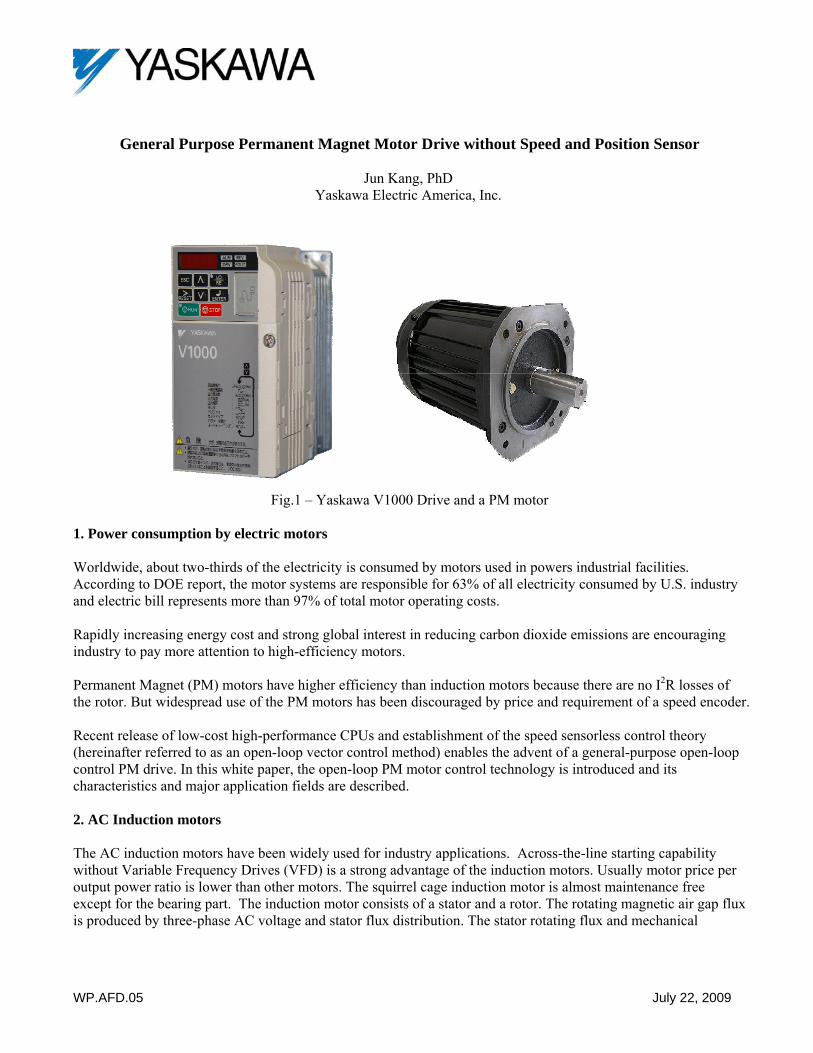
General Purpose Permanent Magnet Motor Drive without Speed and Position Sensor
Jun Kang, PhD Yaskawa Electric America, Inc.
Fig.1 – Yaskawa V1000 Drive and a PM motor
1. Power consumption by electric motors Worldwide, about two-thirds of the electricity is consumed by motors used in powers industrial facilities. According to DOE report, the motor systems are responsible for 63% of all electricity consumed by U.S. industry and electric bill represents more than 97% of total motor operating costs. Rapidly increasing energy cost and strong global interest in reducing carbon dioxide emissions are encouraging industry to pay more attention to high-efficiency motors. Permanent Magnet (PM) motors have higher efficiency than induction motors because there are no I2R losses of the rotor. But widespread use of the PM motors has been discouraged by price and requirement of a speed encoder. Recent release of low-cost high-performance CPUs and establishment of the speed sensorless control theory (hereinafter referred to as an open-loop vector control method) enables the advent of a general-purpose open-loop control PM drive. In this white paper, the open-loop PM motor control technology is introduced and its characteristics and major application fields are described. 2. AC Induction motors The AC induction motors have been widely used for industry applications. Across-the-line starting capability without Variable Frequency Drives (VFD) is a strong advantage of the induction motors. Usually motor price per output power ratio is lower than other motors. The squirrel cage induction motor is almost maintenance free except for the bearing part. The induction motor consists of a stator and a rotor. The rotating magnetic air gap flux is produced by three-phase AC voltage and stator flux distribution. The stator rotating flux and mechanical
WP.AFD.05 July 22, 2009
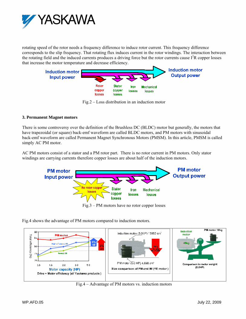
rotating speed of the rotor needs a frequency difference to induce rotor current. This frequency difference corresponds to the slip frequency. That rotating flux induces current in the rotor windings. The interaction between the rotating field and the induced currents produces a driving force but the rotor currents cause I2R copper losses that increase the motor temperature and decrease efficiency.
Fig.2 – Loss distribution in an induction motor
3. Permanent Magnet motors There is some controversy over the definition of the Brushless DC (BLDC) motor but generally, the motors that have trapezoidal (or square) back-emf waveform are called BLDC motors, and PM motors with sinusoidal back-emf waveform are called Permanent Magnet Synchronous Motors (PMSM). In this article, PMSM is called simply AC PM motor. AC PM motors consist of a stator and a PM rotor part. There is no rotor current in PM motors. Only stator windings are carrying currents therefore copper losses are about half of the induction motors.
Fig.3 – PM motors have no rotor copper losses
Fig.4 shows the advantage of PM motors compared to induction motors.
Total efficiency (%)
Fig.4 – Advantage of PM motors vs. induction motors
WP.AFD.05 July 22, 2009
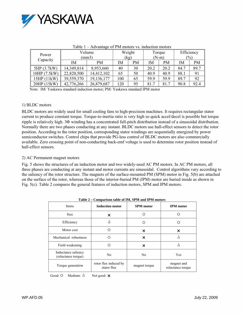
Table 1 – Advantage of PM motors vs. induction motors Volume (mm3)
Weight (kg)
Torque (N-m)
Efficiency (%) Power
Capacity IM PM IM PM IM PM IM PM
5HP (3.7kW) 14,349,814 8,953,660 40 30 20.2 20.2 84.7 89.7 10HP (7.5kW) 22,820,500 14,412,102 65 50 40.9 40.9 88.1 91 15HP (11kW) 39,559,370 19,136,177 100 65 59.9 59.9 89.7 92 20HP (15kW) 42,776,266 26,879,687 120 95 81.7 81.7 90.8 92.4
Note: IM: Yaskawa standard induction motor; PM: Yaskawa standard IPM motor
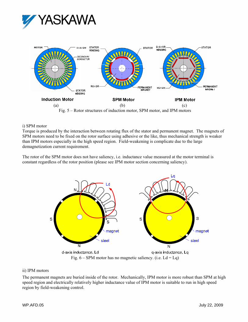
1) BLDC motors BLDC motors are widely used for small cooling fans to high-precision machines. It requires rectangular stator current to produce constant torque. Torque-to-inertia ratio is very high so quick accel/decel is possible but torque ripple is relatively high. 3Φ winding has a concentrated full-pitch distribution instead of a sinusoidal distribution. Normally there are two phases conducting at any instant. BLDC motors use hall-effect sensors to detect the rotor position. According to the rotor position, corresponding stator windings are sequentially energized by power semiconductor switches. Control chips that provide PG-less control of BLDC motors are also commercially available. Zero crossing point of non-conducting back-emf voltage is used to determine rotor position instead of hall-effect sensors. 2) AC Permanent magnet motors Fig. 5 shows the structures of an induction motor and two widely-used AC PM motors. In AC PM motors, all three phases are conducting at any instant and motor currents are sinusoidal. Control algorithms vary according to the saliency of the rotor structure. The magnets of the surface-mounted PM (SPM) motor in Fig. 5(b) are attached on the surface of the rotor, whereas those of the interior-buried PM (IPM) motor are buried inside as shown in Fig. 5(c). Table 2 compares the general features of induction motors, SPM and IPM motors.
Table 2 – Comparison table of IM, SPM and IPM motors
Items Induction motor SPM motor IPM motor
Size Efficiency ∆
Motor cost
Mechanical robustness ∆
Field weakening ∆
Inductance saliency (reluctance torque) No No Yes
Torque generation rotor flux induced by stator flux magnet torque magnet and
reluctance torque
Good: Medium: ∆ Not good:
WP.AFD.05 July 22, 2009
(a) (b) (c)
Fig. 5 – Rotor structures of induction motor, SPM motor, and IPM motors i) SPM motor Torque is produced by the interaction between rotating flux of the stator and permanent magnet. The magnets of SPM motors need to be fixed on the rotor surface using adhesive or the like, thus mechanical strength is weaker than IPM motors especially in the high speed region. Field-weakening is complicate due to the large demagnetization current requirement. The rotor of the SPM motor does not have saliency, i.e. inductance value measured at the motor terminal is constant regardless of the rotor position (please see IPM motor section concerning saliency).
Fig. 6 – SPM motor has no magnetic saliency. (i.e. Ld = Lq)
ii) IPM motors The permanent magnets are buried inside of the rotor. Mechanically, IPM motor is more robust than SPM at high speed region and electrically relatively higher inductance value of IPM motor is suitable to run in high speed region by field-weakening control.
WP.AFD.05 July 22, 2009
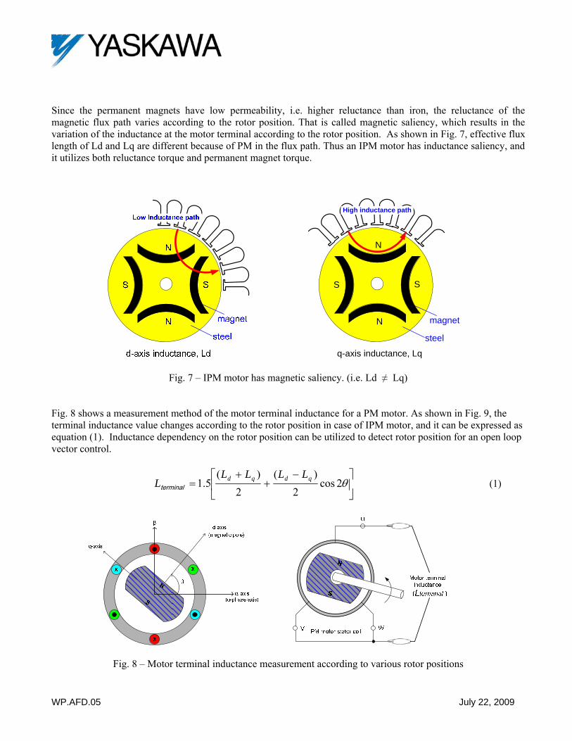
Since the permanent magnets have low permeability, i.e. higher reluctance than iron, the reluctance of the magnetic flux path varies according to the rotor position. That is called magnetic saliency, which results in the variation of the inductance at the motor terminal according to the rotor position. As shown in Fig. 7, effective flux length of Ld and Lq are different because of PM in the flux path. Thus an IPM motor has inductance saliency, and it utilizes both reluctance torque and permanent magnet torque.
q-axis inductance, Lq
N
SS
N magnet
steel
High inductance path
Fig. 7 – IPM motor has magnetic saliency. (i.e. Ld ≠ Lq) Fig. 8 shows a measurement method of the motor terminal inductance for a PM motor. As shown in Fig. 9, the terminal inductance value changes according to the rotor position in case of IPM motor, and it can be expressed as equation (1). Inductance dependency on the rotor position can be utilized to detect rotor position for an open loop vector control.
⎥⎦
⎤⎢⎣
⎡ −+
+= θ2cos
2)(
2)(
5.1 qdqd LLLLLterminal (1)
Fig. 8 – Motor terminal inductance measurement according to various rotor positions
WP.AFD.05 July 22, 2009
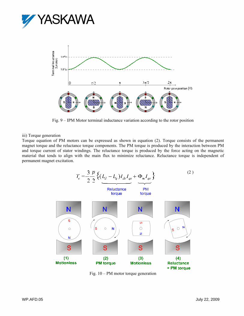
Fig. 9 – IPM Motor terminal inductance variation according to the rotor position iii) Torque generation Torque equation of PM motors can be expressed as shown in equation (2). Torque consists of the permanent magnet torque and the reluctance torque components. The PM torque is produced by the interaction between PM and torque current of stator windings. The reluctance torque is produced by the force acting on the magnetic material that tends to align with the main flux to minimize reluctance. Reluctance torque is independent of permanent magnet excitation.
(2 )
NS
Fig. 10 – PM motor torque generation
WP.AFD.05 July 22, 2009
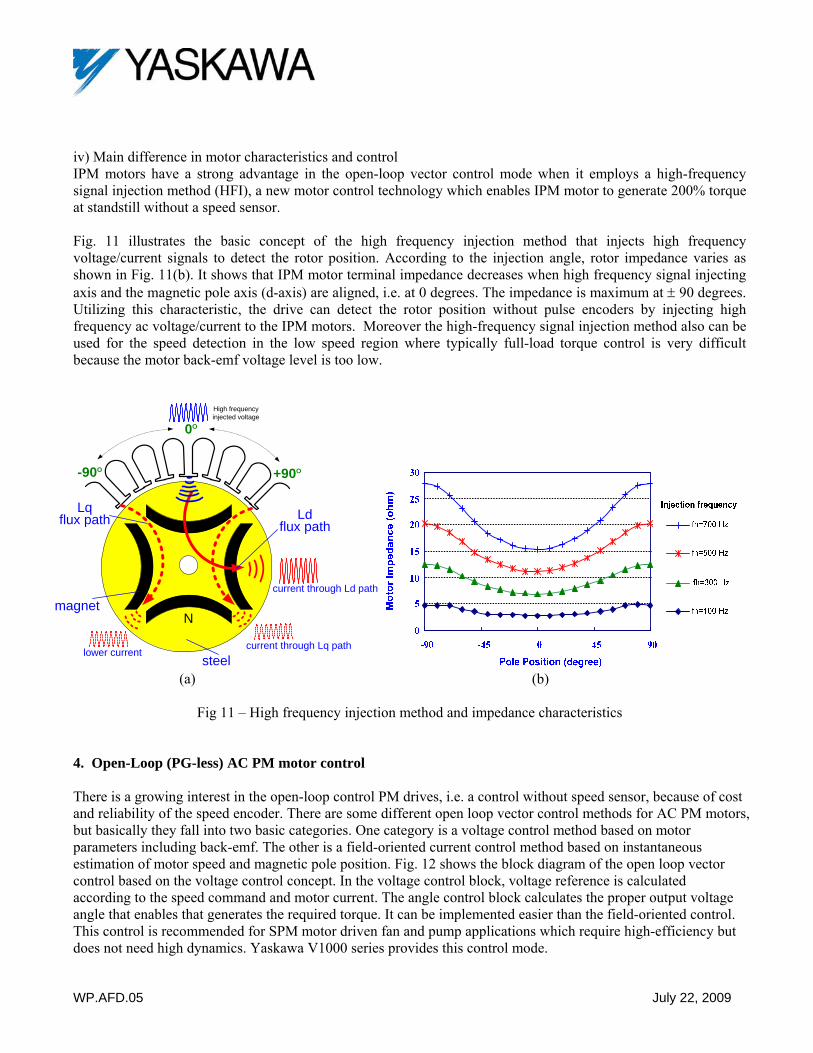
iv) Main difference in motor characteristics and control IPM motors have a strong advantage in the open-loop vector control mode when it employs a high-frequency signal injection method (HFI), a new motor control technology which enables IPM motor to generate 200% torque at standstill without a speed sensor. Fig. 11 illustrates the basic concept of the high frequency injection method that injects high frequency voltage/current signals to detect the rotor position. According to the injection angle, rotor impedance varies as shown in Fig. 11(b). It shows that IPM motor terminal impedance decreases when high frequency signal injecting axis and the magnetic pole axis (d-axis) are aligned, i.e. at 0 degrees. The impedance is maximum at ± 90 degrees. Utilizing this characteristic, the drive can detect the rotor position without pulse encoders by injecting high frequency ac voltage/current to the IPM motors. Moreover the high-frequency signal injection method also can be used for the speed detection in the low speed region where typically full-load torque control is very difficult because the motor back-emf voltage level is too low.
+90O
Nmagnet
steel
-90O
0O
Ld flux path
Lq flux path
lower current
High frequency injected voltage
current through Ld path
current through Lq path
(a) (b)
Fig 11 – High frequency injection method and impedance characteristics
4. Open-Loop (PG-less) AC PM motor control There is a growing interest in the open-loop control PM drives, i.e. a control without speed sensor, because of cost and reliability of the speed encoder. There are some different open loop vector control methods for AC PM motors, but basically they fall into two basic categories. One category is a voltage control method based on motor parameters including back-emf. The other is a field-oriented current control method based on instantaneous estimation of motor speed and magnetic pole position. Fig. 12 shows the block diagram of the open loop vector control based on the voltage control concept. In the voltage control block, voltage reference is calculated according to the speed command and motor current. The angle control block calculates the proper output voltage angle that enables that generates the required torque. It can be implemented easier than the field-oriented control. This control is recommended for SPM motor driven fan and pump applications which require high-efficiency but does not need high dynamics. Yaskawa V1000 series provides this control mode.

WP.AFD.05 July 22, 2009
Fig. 13 shows the block diagram of the field-oriented PG-less control method. The main control blocks consist of a speed estimator, a speed controller, and a current controller. The field-oriented control can be used for applications that need good speed and torque control capabilities. It needs strong computing power to keep tracking magnetic pole-position during operation. It is also sensitive to motor parameters. The motor that has a high impedance saliency ratio such as an IPM motor is very helpful to increase control accuracy collaborating with the high frequency injection method. It has good speed control dynamics with torque limit capability. Yaskawa A1000 series provides both the voltage control method and the field-oriented current control method.
dI
*qV*
dV
eθ
*qV *
dVqI
dI
qI
Fig. 12 – Open loop vector control with voltage control algorithm
estω
estω
*qI
*dI
*qI *
dI
*qV
*dV
*qV *
dV
estω
Fig. 13 – Open loop vector control with current and speed control algorithms
WP.AFD.05 July 22, 2009
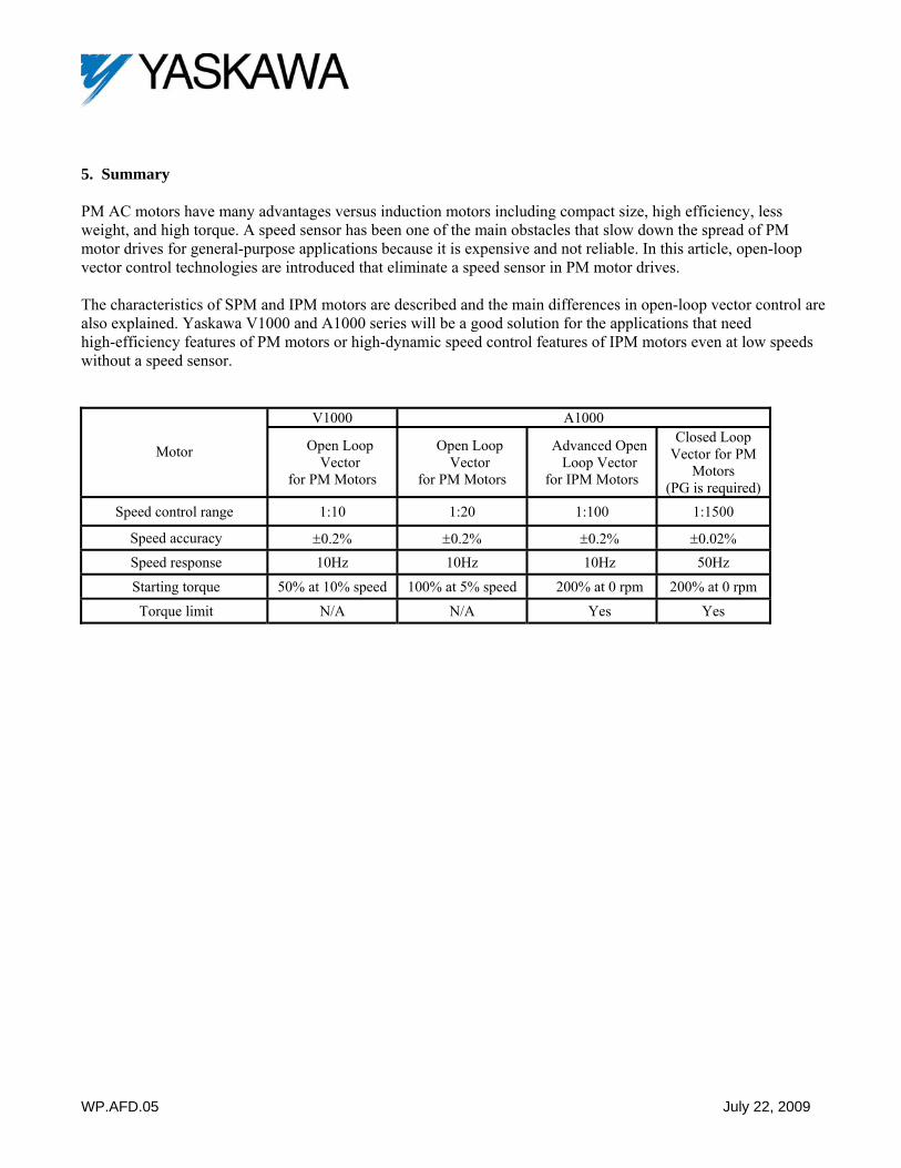
5. Summary PM AC motors have many advantages versus induction motors including compact size, high efficiency, less weight, and high torque. A speed sensor has been one of the main obstacles that slow down the spread of PM motor drives for general-purpose applications because it is expensive and not reliable. In this article, open-loop vector control technologies are introduced that eliminate a speed sensor in PM motor drives. The characteristics of SPM and IPM motors are described and the main differences in open-loop vector control are also explained. Yaskawa V1000 and A1000 series will be a good solution for the applications that need high-efficiency features of PM motors or high-dynamic speed control features of IPM motors even at low speeds without a speed sensor.
V1000 A1000
Motor Open Loop Vector
for PM Motors
Open Loop Vector
for PM Motors
Advanced Open Loop Vector
for IPM Motors
Closed Loop Vector for PM
Motors (PG is required)
Speed control range 1:10 1:20 1:100 1:1500
Speed accuracy ±0.2% ±0.2% ±0.2% ±0.02% Speed response 10Hz 10Hz 10Hz 50Hz
Starting torque 50% at 10% speed 100% at 5% speed 200% at 0 rpm 200% at 0 rpm
Torque limit N/A N/A Yes Yes