Embed Size (px)
Citation preview
General Principles ofDesign, & SafetyDrawing
Office : Phone : F-126, (Lower Basement), Katwaria Sarai, New Delhi-110016 011-26522064Mobile : E-mail:
Web : 8130909220, 9711853908 [email protected], [email protected]
iesmasterpublications.com, iesmaster.org
New Patternfor
UPSC ESE Exam
First Edition : 2016
Second Edition (Revised) : 2017
Typeset at : IES Master Publication, New Delhi-110016
IES MASTER PUBLICATIONF-126, (Lower Basement), Katwaria Sarai, New Delhi-110016
Phone : 011-26522064, Mobile : 8130909220, 9711853908
E-mail : [email protected], [email protected]
Web : iesmasterpublications.com, iesmaster.org
All rights reserved.
Copyright © 2017, by IES MASTER Publications. No part of this booklet may bereproduced, or distributed in any form or by any means, electronic, mechanical,photocopying, recording, or otherwise or stored in a database or retrieval system withoutthe prior permission of IES MASTER, New Delhi. Violates are liable to be legallyprosecuted.
PREFACE
IES Master PublicationNew Delhi, 2017
Giving life to an engineer’s dream for the betterment of society involves Design, Drawing and Safety. Withthe increasing complexities of economy, as well as the ensuing disruption in IT, besides the stringent safetyrules, this inter-disciplinary subject has become challenging to comprehend from exam point of view.
Looking at the nature of Engineering Services Examination (ESE), and the level of questions being asked,the conventional approach of preparing through theory and examples does not serve the purpose. This bookattempts to provide logical reasoning through mathematical analysis, gives a clear insight into the concepts,and paints a complete picture in front of your eyes. For students to discover the extent of their learning,practice questions have been provided at the end of this book.
In their endeavour to give students the best, Mr. Bipin Thakur has shared his subject knowledge of Designand Safety, and Mr. Himadri Shekhar (Aahil) that of Drawing in this book in an easy to understandlanguage that gives in a complete clarity of thought. As a result, what students get is their collective wisdomthat breaks free the constraints of engineering students in appreciating the General Principles of Design,Drawing and Safety.
As you navigate through this book, a slew of diagrams, flow charts, mind maps and tables, pack a tangothat your eyes can relish on. This book is an ESE aspirant’s delight that communicates, connects, and buildsupon the exam preparedness right up to the standards of the UPSC.
Section Description Page No.
Preface (iii)
Engineering Drawing 01-134
Chapter 1 INTRODUCTION TO ENGINEERING DRAWING 1 – 08
1.1 Introduction …(1)
1.2 Drawing Sheets : [IS 10711 : 2001] …(1)
1.3 Drawing Board : [IS 1444 : 1989] …(2)
1.4 Scales …(3)
1.5 Mini Drafter …(3)
1.6 T-Square …(3)
1.7 Set Square …(3)
1.8 Protactor …(4)
1.9 Compass …(4)
1.10 Dividers …(5)
1.11 Drawing Pencil …(5)
1.12 French Curves …(5)
1.13 Layout of a Drawing Sheet …(6)
Chapter 2 LINES, LETTERING AND DIMENSIONING 09 – 21
2.1 Lines : [IS 10714 (Part 20) : 2001 and SP46 : 2003] …(9)
2.2 Lettering [IS 9609 : 2001] …(10)
2.3 Dimensioning [IS 11669 : 1986] …(11)
2.4 Methods of Dimensioning …(12)
2.5 Arrangement of Dimensions …(13)
2.6 Dimensioning of Various Objects …(13)
2.7 Symbols and Abbreviations Used in Dimensioning …(15)
2.8 General Rules of Dimensioning …(15)
CONTENTS
Contents (v)
Chapter 3 GEOMETRICAL CONSTRUCTIONS 22 – 26
3.1 Introduction …(22)
3.2 Basic Geometrical Shapes …(22)
Chapter 4 SCALES 27 – 34
4.1 Introduction …(34)
4.2 Representative Fraction (R.F.) …(27)
4.3 Units of Length and their Conversion …(28)
4.4 Types of Scales …(28)
Chapter 5 ENGINEERING CURVES 35 – 62
5.1 Introduction …(35)
5.2 Conic Sections or Conics …(35)
5.3 Special Curves …(42)
5.4 Plane Curves …(42)
5.5 Space Curves …(56)
Chapter 6 THEORY OF PROJECTIONS 63 – 74
6.1 Introduction …(63)
6.2 Projejction Methods …(63)
Chapter 7 PROJECTIONS OF POINTS 75 – 83
7.1 Introduction …(75)
7.2 Locations of a Point …(76)
7.3 Summary …(81)
Chapter 8 PROJECTIONS OF LINES 84 – 99
8.1 Introduction …(84)
8.2 Bis Conventions for Projection of Lines …(84)
8.3 Different orientation of lines and their projections …(84)
8.4 Traces of a line …(94)
8.5 Auxiliary Plane Projection Method …(95)
Chapter 9 PROJECTION OF PLANES 100 – 106
9.1 Introduction …(100)
9.2 Orientation of Planes and their Projections …(100)
Chapter 10 PROJECTIONS OF SOLIDS 107 – 119
10.1 Introduction …(107)
(vi) Contents
10.2 Right Solid …(107)
10.3 Frustums and Truncated Solid …(108)
10.4 Orientation of Solid and their Projections …(109)
10.5 Suspended Solids …(112)
10.6 Section of Solids …(113)
10.7 Intersection of Surfaces of Solids …(114)
Chapter 11 DEVELOPMENT OF SURFACES 120 – 134
11.1 Introduction …(120)
11.2 Methods of Development of Lateral Surfaces …(121)
11.3 Isometric Projection …(128)
Engineering Design 135-186
Chapter 1 INTRODUCTION 135 – 141
1.1 Types of Engineering Design …(135)
1.2 Importance of Engineering Design …(136)
1.3 The Design Process …(136)
Chapter 2 CONCEPTUAL DESIGN 142 – 158
2.1 Introduction …(142)
2.2 Problem Definition …(142)
2.3 Gather Information …(148)
2.4 Concept Generation …(148)
2.5 Evaluation Method …(154)
Chapter 3 EMBODIMENT DESIGN 159 – 163
3.1 Introduction …(159)
3.2 Product Architecture …(159)
3.3 Configuration Design …(162)
3.4 Parametric Design …(162)
Chapter 4 DETAIL DESIGN 164 – 164
4.1 Introduction …(164)
4.2 Product Lifecycle Management (PLM) …(164)
Contents (vii)
Chapter 5 PROBLEM-SOLVING TOOLS 164 – 175
5.1 Introduction …(164)
5.2 Problem Definition …(165)
5.3 Cause Finding …(166)
5.4 Solution Planning and Implementation …(168)
Engineering Safety 187-237
Chapter 1 INTRODUCTION 187 – 191
1.1 Safety …(187)
1.2 What is an Accidents …(187)
1.3 Accident Causation Theories …(188)
Chapter 2 HAZARD AND HAZARD ANALYSIS 191 – 199
2.1 Introduction …(191)
2.2 Hazard Analysis Methods and Techniques …(192)
2.3 Hazard Control …(198)
Chapter 3 RISK ANALYSIS AND MANAGEMENT 199 – 203
3.1 Risk Management …(199)
3.2 Risk Analysis Process and Methods …(201)
3.3 Role of ‘it’ in Health and Safety Management …(202)
3.4 Social Dimension of Risk-Contemporary Thinking …(202)
3.5 Evaulating Risk in Design …(202)
3.6 Risk Control Measures …(203)
Chapter 4 HUMAN FACTORS IN SAFETY 203 – 206
4.1 Job Stress …(203)
4.2 Occuptational Stressors and Workplace Stress Effects …(203)
4.3 Physical Stress Influencing Factors …(204)
4.4 Human Operator’s Stress Characteristics …(204)
4.5 Worksite Analysis Program for Human Factors …(205)
Chapter 5 SAFETY MANAGEMENT PRINCIPLES 206 – 213
5.1 Introduction …(206)
5.2 Safety Management Principles …(207)
5.3 Responsibilities Non-Safety Managers …(208)
(viii) Contents
5.4 Safety Committees …(208)
5.5 Improving the Workplace Ergonomics …(209)
5.6 Safety Audit …(210)
5.7 Safety Survey …(212)
5.8 Emergency Preparedness and Response Planning (EPRP) in MajorAccident Hazard Factories …(212)
Chapter 6 INITIATIVES TOWARDS SAFETY – GOI 213 – 221
6.1 Existing Set-up of Occupational Safety and Healthin the Workplace in India …(213)
6.2 Government Bodies Dealing with OSH Regulations …(214)
6.3 National Level Autonomous Bodies/OrganizationsConnected with Occupational Safety & Health …(215)
6.4 12th Five Year Plan Schemes in Respect to Safety …(216)
6.5 Existing Scenario of Occupational Safety and Healthin Various Segments of Unorganised Sector …(217)
6.6 Relevant Legislation in India …(220)
Chapter 7 MISCELLANEOUS 222 – 223
7.1 Occupational Health Problem …(222)
7.2 International Labour Organization …(223)
7.3 OSHA [Occupational Safety and Health Administration] …(223)
GLOSSARY 224-228
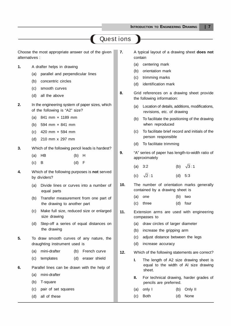
INTRODUCTION TO ENGINEERING DRAWING | 7
Choose the most appropriate answer out of the givenalternatives :
1. A drafter helps in drawing
(a) parallel and perpendicular lines
(b) concentric circles
(c) smooth curves
(d) all the above
2. In the engineering system of paper sizes, whichof the following is “A2” size?
(a) 841 mm × 1189 mm
(b) 594 mm × 841 mm
(c) 420 mm × 594 mm
(d) 210 mm x 297 mm
3. Which of the following pencil leads is hardest?
(a) HB (b) H
(c) B (d) F
4. Which of the following purposes is not servedby dividers?
(a) Divide lines or curves into a number ofequal parts
(b) Transfer measurement from one part ofthe drawing to another part
(c) Make full size, reduced size or enlargedsize drawing
(d) Step-off a series of equal distances onthe drawing
5. To draw smooth curves of any nature, thedraughting instrument used is
(a) mini-drafter (b) French curve
(c) templates (d) eraser shield
6. Parallel lines can be drawn with the help of
(a) mini-drafter
(b) T-square
(c) pair of set squares
(d) all of these
Questions
7. A typical layout of a drawing sheet does notcontain
(a) centering mark
(b) orientation mark
(c) trimming marks
(d) identification mark
8. Grid references on a drawing sheet providethe following information:
(a) Location of details, additions, modifications,revisions, etc. of drawing
(b) To facilitate the positioning of the drawingwhen reproduced
(c) To facilitate brief record and initials of theperson responsible
(d) To facilitate trimming
9. “A” series of paper has length-to-width ratio ofapproximately
(a) 3:2 (b) 3 :1
(c) 2 :1 (d) 5:3
10. The number of orientation marks generallycontained by a drawing sheet is
(a) one (b) two
(c) three (d) four
11. Extension arms are used with engineeringcompasses to
(a) draw circles of larger diameter
(b) increase the gripping arm
(c) adjust distance between the legs
(d) increase accuracy
12. Which of the following statements are correct?
I. The length of A2 size drawing sheet isequal to the width of Al size drawingsheet.
II. For technical drawing, harder grades ofpencils are preferred.
(a) only I (b) Only II
(c) Both (d) None
8 | ENGINEERING DRAWING
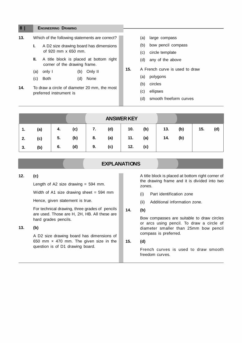
13. Which of the following statements are correct?
I. A D2 size drawing board has dimensionsof 920 mm x 650 mm.
II. A title block is placed at bottom rightcorner of the drawing frame.
(a) only I (b) Only II
(c) Both (d) None
14. To draw a circle of diameter 20 mm, the mostpreferred instrument is
(a) large compass
(b) bow pencil compass
(c) circle template
(d) any of the above
15. A French curve is used to draw
(a) polygons
(b) circles
(c) ellipses
(d) smooth freeform curves
1. (a)
2. (c)
3. (b)
4. (c)
5. (b)
6. (d)
7. (d)
8. (a)
9. (c)
10. (b)
11. (a)
12. (c)
13. (b)
14. (b)
ANSWER KEY
15. (d)
12. (c)
Length of A2 size drawing = 594 mm.
Width of A1 size drawing sheet = 594 mm
Hence, given statement is true.
For technical drawing, three grades of pencilsare used. Those are H, 2H, HB. All these arehard grades pencils.
13. (b)
A D2 size drawing board has dimensions of650 mm × 470 mm. The given size in thequestion is of D1 drawing board.
EXPLANATIONS
A title block is placed at bottom right corner ofthe drawing frame and it is divided into twozones.
(i) Part identification zone
(ii) Additional information zone.
14. (b)
Bow compasses are suitable to draw circlesor arcs using pencil. To draw a circle ofdiameter smaller than 25mm bow pencilcompass is preferred.
15. (d)
French curves is used to draw smoothfreedom curves.