Embed Size (px)
Citation preview
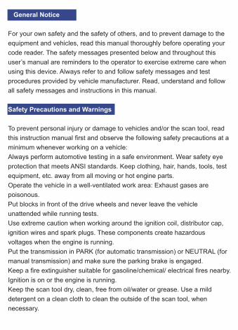
General Notice
For your own safety and the safety of others, and to prevent damage to the
equipment and vehicles, read this manual thoroughly before operating your
code reader. The safety messages presented below and throughout this
user’s manual are reminders to the operator to exercise extreme care when
using this device. Always refer to and follow safety messages and test
procedures provided by vehicle manufacturer. Read, understand and follow
all safety messages and instructions in this manual.
Safety Precautions and Warnings
To prevent personal injury or damage to vehicles and/or the scan tool, read
this instruction manual first and observe the following safety precautions at a
minimum whenever working on a vehicle:
Always perform automotive testing in a safe environment. Wear safety eye
protection that meets ANSI standards. Keep clothing, hair, hands, tools, test
equipment, etc. away from all moving or hot engine parts.
Operate the vehicle in a well-ventilated work area: Exhaust gases are
poisonous.
Put blocks in front of the drive wheels and never leave the vehicle
unattended while running tests.
Use extreme caution when working around the ignition coil, distributor cap,
ignition wires and spark plugs. These components create hazardous
voltages when the engine is running.
Put the transmission in PARK (for automatic transmission) or NEUTRAL (for
manual transmission) and make sure the parking brake is engaged.
Keep a fire extinguisher suitable for gasoline/chemical/ electrical fires nearby.
Ignition is on or the engine is running.
Keep the scan tool dry, clean, free from oil/water or grease. Use a mild
detergent on a clean cloth to clean the outside of the scan tool, when
necessary.
Warranty and Servic Limited One Year Warranty
We warrants to its customers that this product will be free from all defects in
materials and workmanship for a period of one (1) year from the date of the
original purchase, subject to the following terms and conditions:
1) The sole responsibility of our company under the Warranty is limited to
either the repair or, at the option of our company, replacement of the scan
tool at no charge with Proof of Purchase. The sales receipt may be used for
this purpose.
2) This warranty does not apply to damages caused by improper use,
accident, flood, lightning, or if the product was altered or repaired Center.
3) We shall not be liable for any incidental or consequential damages
arising from the use, misuse, or mounting of the scan tool. Some states do
not allow limitations on how long an implied warranty lasts, so the above
limitations may not apply to you.
1.1 On-Board Diagnostics (OBD) II
1 General Information
The first generation of On-Board Diagnostics (called OBD I) was
developed by the California Air Resources Board (ARB) and
implemented in 1988 to monitor some of the emission control
components on vehicles. As technology evolved and the desire to
improve the On-Board Diagnostic system increased, a new generation
of On-Board Diagnostic system was developed. This second generation
of On-Board Diagnostic regulations is called “OBD II”.The OBD II
system is designed to monitor emission control systems and key engine
components by performing either continuous or periodic tests of specific
components and vehicle conditions. When a problem is detected, the
OBD II system turns on a warning lamp (MIL) on the vehicle instrument
panel to alert the driver typically by the phrase of “Check Engine” or
“Service Engine Soon”.
The system will also store important information about the detected
malfunction so that a technician can accurately find and fix the problem.
Here below follow
three pieces of such valuable information:
1) Whether the Malfunction Indicator Light (MIL) is commanded ‘on’ or
‘off’;
2) Which, if any, Diagnostic Trouble Codes (DTCs) are stored;
3) Readiness Monitor status.
1.2 Location of the Data Link Connector
The DLC (Data Link Connector or Diagnostic Link Connector) is the
standardized 16-cavity connector where diagnostic code readers
interface with the vehicle’s on-board computer. The DLC is usually
located 12 inches from the center of the instrument panel (dash), under
or around the driver’s side for most vehicles. If Data Link Connector is
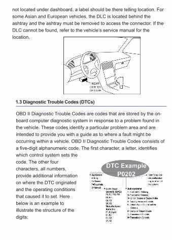
not located under dashboard, a label should be there telling location. For
some Asian and European vehicles, the DLC is located behind the
ashtray and the ashtray must be removed to access the connector. If the
DLC cannot be found, refer to the vehicle’s service manual for the
location.
1.3 Diagnostic Trouble Codes (DTCs)
OBD II Diagnostic Trouble Codes are codes that are stored by the on-
board computer diagnostic system in response to a problem found in
the vehicle. These codes identify a particular problem area and are
intended to provide you with a guide as to where a fault might be
occurring within a vehicle. OBD II Diagnostic Trouble Codes consists of
a five-digit alphanumeric code. The first character, a letter, identifies
which control system sets the
code. The other four
characters, all numbers,
provide additional information
on where the DTC originated
and the operating conditions
that caused it to set. Here
below is an example to
illustrate the structure of the
digits:
1.4 OBD II Monitor Readiness Statuses
�OBD II systems must indicate whether or not the vehicle’ s PCM’ � s
monitor system has completed testing on each component.
Components that have been tested will be reported as “Ready”, or
“complete”, meaning they have been tested by the OBD II system. The
purpose of recording readiness states is to allow inspectors to
determine if vehicle’ s OBD II system has tested all the components
and/or systems.�The power train control module (PCM) sets a monitor
to “Ready” or “Complete”, it will remain in this state. A number of
factors, including erasing of diagnostic trouble codes (DTCs) with a
scan tool or a disconnected battery, can result in Readiness Monitors
being set to “Not ready”. Since the three continuous monitors are
constantly evaluating, they will be reported as “Ready” all of the time. If
testing of a particular supported non-continuous monitor has not been
completed, the monitor status will be reported as “Not Complete” or
“Not Ready” .
In order for the OBD monitor system to become ready, the vehicle
should be driven under a variety of normal operating conditions. These
operating conditions may include a mix of highway driving and stop and
go, city type driving, and at least one overnight-off period. For specific
information on getting your vehicle’ s OBD monitor system ready,
please consult your vehicle owners manual.
2 Use the scan tool
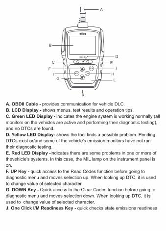
2.1 Tool Descriptions
This section illustrates external features, ports and connectors of the
code reader.
2.2 Accessory Descriptions
This section lists the accessories that go with the code reader. If you
find any of the following items missing from your package, contact your
local dealer for assistance.
1 User’s Guide - provides operation instructions for the usage of the
code reader.
2 USB Cable- provides connection between the code reader and a
computer to upgrade the tool.
2.3 Technical Specifications
2.4 Accessories Included
User manual
USB cable
OBDII/EOBD Code Reader
3 Getting Started3.1 Connecting to Vehicle
3 Getting Started
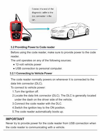
Before using the code reader, make sure to provide power to the code
reader.
The unit operates on any of the following sources:
● 12-volt vehicle power
● USB connection to personal computer.
3.2 Providing Power to Code reader
3.2.1 Connecting to Vehicle Power
The code reader normally powers on whenever it is connected to the
data link connector (DLC).
To connect to vehicle power:
1.Turn the ignition off.
2.Locate the data link connector (DLC). The DLC is generally located
under the dash on the driver side of the vehicle.
3.Connect the code reader with the DLC.
4.Switch the ignition key to the ON position.
5.The code reader automatically boots up.
IMPORTANT
Never try to provide power for the code reader from USB connection when
the code reader is communicating with a vehicle.
3.2.2 Connecting to Personal Computer with USB Cable
The code reader also receives power through the USB port when it is
connected to a PC for updating software and transferring saved files.
To connect to PC:
1.Insert the small end of the USB cable to the USB port at the right
side of the code reader and the large end to a computer.
2.Press the power switch of the code reader to power it on.
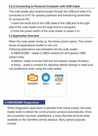
3.3 Application Overview
When the code reader boots up, the Home screen opens. This screen
shows all applications loaded on the unit.
Following applications are preloaded into the code reader:
● OBDII/EOBD – leads to OBDII screens for all 9 generic OBD
system tests.
● Battery– leads to screen that test and display voltage of battery.
● Setup – leads to screens for adjusting default settings to meet your
own preference when using the code reader.
When Diagnostics application is selected from Home screen, the code
reader starts to detect the communication protocol automatically. Once
the connection has been established, a menu that lists all of the tests
available on the identified vehicle displays. Menu options typically
include:
4 OBDII/EOBD Diagnostics
● Read Codes
● Freeze Frame Data
● Erase Codes
● Live Data
● I/M Readiness
● Vehicle Information
● Unit of measure
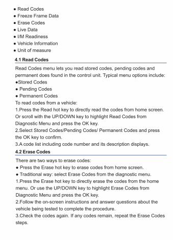
4.1 Read Codes
Read Codes menu lets you read stored codes, pending codes and
permanent does found in the control unit. Typical menu options include:
●Stored Codes
● Pending Codes
● Permanent Codes
To read codes from a vehicle:
1.Press the Read hot key to directly read the codes from home screen.
Or scroll with the UP/DOWN key to highlight Read Codes from
Diagnostic Menu and press the OK key.
2.Select Stored Codes/Pending Codes/ Permanent Codes and press
the OK key to confirm.
3.A code list including code number and its description displays.
4.2 Erase Codes
There are two ways to erase codes:
● Press the Erase hot key to erase codes from home screen.
● Traditional way: select Erase Codes from the diagnostic menu.
1.Press the Erase hot key to directly erase the codes from the home
menu. Or use the UP/DOWN key to highlight Erase Codes from
Diagnostic Menu and press the OK key.
2.Follow the on-screen instructions and answer questions about the
vehicle being tested to complete the procedure.
3.Check the codes again. If any codes remain, repeat the Erase Codes
steps.

Freeze Frame menu displays freeze frame data, a snapshot of critical
vehicle operating conditions automatically recorded by the on-board
computer at the time of the DTC set. It is a good function to help
determine what caused the fault.
To view freeze frame data:
1.Select View Freeze Frame from the Diagnostic Menu. Details of freeze
frame data displays.
2.Use the up and down arrow keys to scroll through data to select lines.
If no freeze frame detected, the message “No freeze frame data stored!”
is displayed.
3. Use the ESC key to return to Diagnostic Menu.
4.3 Live Data
Live Data menu lets you view real time PID data from the electronic
control module.
4.3.1 Complete Data Set
The Complete Data Set function allows real time viewing of the vehicle’s
electronic control unit’s PID data, including sensor data, operation of
switches, solenoids and relays.
8. Select YES to view the definition of each parameter; pick ESC key to
return to the previous menu.
4.3.2 Unit of Measure
Unit of Measure allows you to switch from English and Metric.
4.4 View Freeze Frame
4.5 Read I/M Readiness Status Data
I/M Readiness option allows to view a snapshot of the operations for the
emission system on OBDII/EOBD vehicles.
I/M Readiness is a useful function used to check if all monitors are OK
or N/A. The vehicle’s computer performs tests on the emission system
during normal driving conditions. After a specific amount of drive time
(each monitor has specific driving conditions and time required), the
computer’s monitors decide if the vehicles emission system is working
correctly.
When the monitor’s status is:
● OK - vehicle was driven enough to complete the monitor.
● INC (Incomplete) - vehicle was not driven enough to complete the
monitor.
● N/A (Not Applicable) - vehicle does not support that monitor.
There are two types of I/M Readiness tests:
●Since DTCs Cleared - shows status of the monitors since the DTCs
were last cleared.
● This Drive Cycle - shows status of monitors since the start of the
current drive cycle.
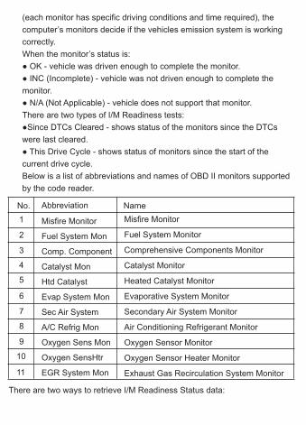
Below is a list of abbreviations and names of OBD II monitors supported
by the code reader.
No. Abbreviation Name
1
2
3
4
5
6
7
8
9
10
11
Misfire Monitor
Fuel System Mon
Comp. Component
Catalyst Mon
Htd Catalyst
Evap System Mon
Sec Air System
A/C Refrig Mon
Oxygen Sens Mon
Oxygen SensHtr
EGR System Mon
Misfire Monitor
Fuel System Monitor
Comprehensive Components Monitor
Catalyst Monitor
Heated Catalyst Monitor
Evaporative System Monitor
Secondary Air System Monitor
Air Conditioning Refrigerant Monitor
Oxygen Sensor Monitor
Oxygen Sensor Heater Monitor
Exhaust Gas Recirculation System Monitor
There are two ways to retrieve I/M Readiness Status data:
● One-click I/M readiness key
● Typical way: select I/M Readiness from Diagnostic Menu
NOTE
●To review I/M Readiness status, make sure that the ignition key is
switched to ON with the engine off.
●Not all monitors are supported by all vehicles.
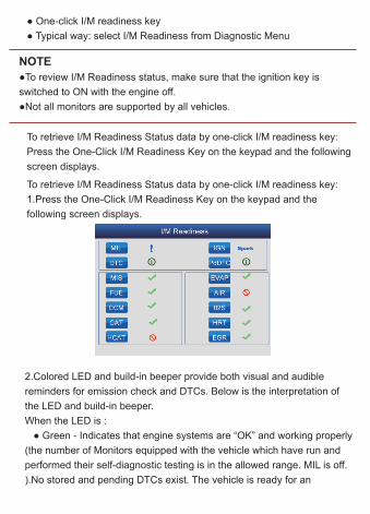
To retrieve I/M Readiness Status data by one-click I/M readiness key:
Press the One-Click I/M Readiness Key on the keypad and the following
screen displays.
2.Colored LED and build-in beeper provide both visual and audible
reminders for emission check and DTCs. Below is the interpretation of
the LED and build-in beeper.
When the LED is :
● Green - Indicates that engine systems are “OK” and working properly
(the number of Monitors equipped with the vehicle which have run and
performed their self-diagnostic testing is in the allowed range. MIL is off.
).No stored and pending DTCs exist. The vehicle is ready for an
To retrieve I/M Readiness Status data by one-click I/M readiness key:
1.Press the One-Click I/M Readiness Key on the keypad and the
following screen displays.
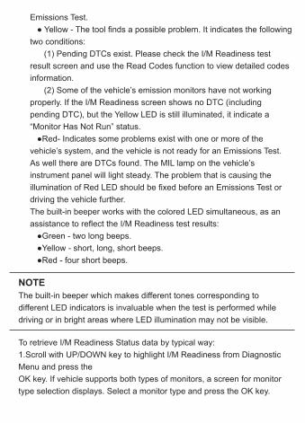
Emissions Test.
● Yellow - The tool finds a possible problem. It indicates the following
two conditions:
(1) Pending DTCs exist. Please check the I/M Readiness test
result screen and use the Read Codes function to view detailed codes
information.
(2) Some of the vehicle’s emission monitors have not working
properly. If the I/M Readiness screen shows no DTC (including
pending DTC), but the Yellow LED is still illuminated, it indicate a
“Monitor Has Not Run” status.
●Red- Indicates some problems exist with one or more of the
vehicle’s system, and the vehicle is not ready for an Emissions Test.
As well there are DTCs found. The MIL lamp on the vehicle’s
instrument panel will light steady. The problem that is causing the
illumination of Red LED should be fixed before an Emissions Test or
driving the vehicle further.
The built-in beeper works with the colored LED simultaneous, as an
assistance to reflect the I/M Readiness test results:
●Green - two long beeps.
●Yellow - short, long, short beeps.
●Red - four short beeps.
NOTE
The built-in beeper which makes different tones corresponding to
different LED indicators is invaluable when the test is performed while
driving or in bright areas where LED illumination may not be visible.
To retrieve I/M Readiness Status data by typical way:
1.Scroll with UP/DOWN key to highlight I/M Readiness from Diagnostic
Menu and press the
OK key. If vehicle supports both types of monitors, a screen for monitor
type selection displays. Select a monitor type and press the OK key.
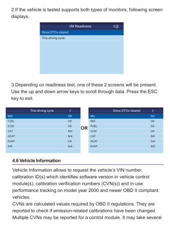
2.If the vehicle is tested supports both types of monitors, following screen
displays.
I/M Readiness
Since DTCs cleared
This driving cycle
1/2
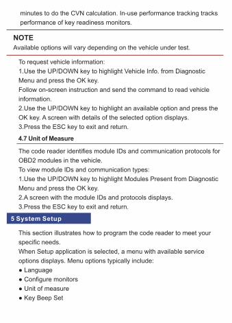
3.Depending on readiness test, one of these 2 screens will be present.
Use the up and down arrow keys to scroll through data. Press the ESC
key to exit.
This driving cycle
MIS
FUEL
CCM
CAT
HCAT
EVAP
AIR
1
OK
OK
OK
INC
N/A
OK
N/A
Since DTCs cleared
MIL
MIS
FUEL
CCM
CAT
HCAT
EVAP
1
NO
OK
OK
OK
INC
N/A
INC
OR
4.6 Vehicle Information
Vehicle Information allows to request the vehicle’s VIN number,
calibration ID(s) which identifies software version in vehicle control
module(s), calibration verification numbers (CVN(s)) and in-use
performance tracking on model year 2000 and newer OBD II compliant
vehicles.
CVNs are calculated values required by OBD II regulations. They are
reported to check if emission-related calibrations have been changed.
Multiple CVNs may be reported for a control module. It may take several
minutes to do the CVN calculation. In-use performance tracking tracks
performance of key readiness monitors.
NOTE
Available options will vary depending on the vehicle under test.
To request vehicle information:
1.Use the UP/DOWN key to highlight Vehicle Info. from Diagnostic
Menu and press the OK key.
Follow on-screen instruction and send the command to read vehicle
information.
2.Use the UP/DOWN key to highlight an available option and press the
OK key. A screen with details of the selected option displays.
3.Press the ESC key to exit and return.
4.7 Unit of Measure
The code reader identifies module IDs and communication protocols for
OBD2 modules in the vehicle.
To view module IDs and communication types:
1.Use the UP/DOWN key to highlight Modules Present from Diagnostic
Menu and press the OK key.
2.A screen with the module IDs and protocols displays.
3.Press the ESC key to exit and return.
5 System Setup
This section illustrates how to program the code reader to meet your
specific needs.
When Setup application is selected, a menu with available service
options displays. Menu options typically include:
● Language
● Configure monitors
● Unit of measure
● Key Beep Set
● Diag Beep Set
● Tool self-test
● Update Mode
5.1 Select Language
Selecting Language opens a screen that allows you to choose system
language.
5.2 Configure Monitors
This menu allows the users to configure the monitors required to test
spark ignition and compression ignition, the number of monitors to pass
diagnosis, and restore the default settings. Menu options typically
include:
● Spark IGN Required Monitors
● Compression IGN Required Monitors
● Allowed INC Monitors
● Reset Factory Default
There are two different types of monitors: continuous and non-
continuous. Continuous monitors are different in design from the non-
continuous monitors. Continuous monitors are being constantly tested
and evaluated by the car’s computer while the car is running.
Conversely, the non-continuous monitors require certain conditions to be
met before a test or series of tests can be completed.
Continuous Monitors:
● Misfire
● Fuel System
● Comprehensive Component
Non-Continuous Monitors:
NOTE
Non-continuous monitors are different for spark ignition cars (gasoline
engines) and compression ignition card (diesel engines).
Spark ignition vehicles (Gas)
● Catalyst (CAT)
● Heated Catalyst
● Evaporative (EVAP) System
● Secondary Air System
● Oxygen (O2) Sensor
● Oxygen Sensor Heater
● EGR (Exhaust Gas Recirculation) and/or VVT System
Compression ignition vehicles (Diesel)
● NMHC Catalyst
● NOx/SCR After treatment
● Boost Pressure
● Exhaust Gas Sensor
● PM Filter
● EGR and/or VVT System
To configure monitors:
1.Use the UP/DOWN key to highlight Configure Monitors from Setup
menu and press the OK key to confirm.
5.2.1 Spark IGN Required Monitors
In this menu, the operators can configure monitors for spark ignition cars
(gasoline engines).
To configure spark IGN required monitors:
1.Use the UP/DOWN key to highlight Spark IGN Required Monitors from
menu and press the OK key to confirm.
2.The custom monitors selection screen displays.
Use the ESC key to select or deselect a monitor. Press the OK key to
confirm.
NOTE
The number to the upper right corner of display indicates the total number
of optional monitors and sequence of currently selected monitor.
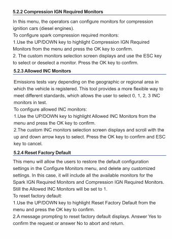
5.2.2 Compression IGN Required Monitors
In this menu, the operators can configure monitors for compression
ignition cars (diesel engines).
To configure spark compression required monitors:
1.Use the UP/DOWN key to highlight Compression IGN Required
Monitors from the menu and press the OK key to confirm.
2. The custom monitors selection screen displays and use the ESC key
to select or deselect a monitor. Press the OK key to confirm.
5.2.3 Allowed INC Monitors
Emissions tests vary depending on the geographic or regional area in
which the vehicle is registered. This tool provides a more flexible way to
meet different standards, which allows the user to select 0, 1, 2, 3 INC
monitors in test.
To configure allowed INC monitors:
1.Use the UP/DOWN key to highlight Allowed INC Monitors from the
menu and press the OK key to confirm.
2.The custom INC monitors selection screen displays and scroll with the
up and down arrow keys to select. Press the OK key to confirm and ESC
key to cancel.
5.2.4 Reset Factory Default
This menu will allow the users to restore the default configuration
settings in the Configure Monitors menu, and delete any customized
settings. In this case, it will include all the available monitors for the
Spark IGN Required Monitors and Compression IGN Required Monitors.
Still the Allowed INC Monitors will be set to 1.
To reset factory default:
1.Use the UP/DOWN key to highlight Reset Factory Default from the
menu and press the OK key to confirm.
2.A message prompting to reset factory default displays. Answer Yes to
confirm the request or answer No to abort and return.
5.3 Unit of measure
Unit of measure opens a dialog box that allows you to choose between
US customary or metric units of measure.
To change the unit setup:
1.Scroll the UP/DOWN keys to highlight Unit of Measure from Setup
menu and press the OK key.
2.Press the UP/DOWN arrow key select an item and press the OK key to
save and return.
Key beep set opens a dialog box that allows you to turn on/off the built-in
speaker for key pressing.
To set the key beep:
1.Use the UP/DOWN key to highlight Key beep set from Setup menu and
press the OK key.
2.Press the UP/DOWN arrow key select an item and press the OK key to
save and return.
5.5 Diag Beep Set
5.4 Key Beep Set
Key beep set opens a dialog box that allows you to turn on/off the built-in
speaker when performing diagnostics.
To set the Diag. beep:
1.Use the UP/DOWN key to highlight Key Beep Set from Setup menu
and press the OK key.
2.Press the UP/DOWN key to select an item and press the OK key to
save and return.
5.6 Tool Self-test
Key beep set opens a dialog box that allows you to check if the LCD
display and the operation of keypad and LED are working correctly.
Typical menu includes:
● Display Test
● Keypad Test
● LED Test
5.6.1 Display Test
Selecting Display Test option opens a screen that allows you to check the
functionality of the display.
To test the display:
1.Use the UP/DOWN key to highlight Display Test from Setup menu and
press the OK key to start test.
2.Check if there are any missing spots in the LCD screen.
3.To quit the test, press the ESC key.
5.6.2 Keypad Test
Selecting Key Test option opens a screen that allows you to check the
functionality of the keypad.
To test the keypad:
1.Use the UP/DOWN key to highlight Keyboard Test from Setup menu
and press the OK key.
2.Press any key to start test. Key name or scroll direction should show
on display when you press a key. Double press ESC to return.
5.6.3 LED Test
Selecting LED Test option opens a screen that allows you to check the
functionality of the LED.
To test the LED:
1.Use the UP/DOWN key to highlight LCD Test from Setup menu and
press the OK key to start test.
2.Scroll with the up and down arrow keys to select the desired LED
lamps to check. The LED should turn on/off according to the selected
commands.
3.To quit the test, press the ESC key.
5.7 Update Mode
This function allows you enter the update model automatically. For
details, please refer to 7.1.
6 Tool Information
Selecting About option opens a screen that shows information about
your code reader, such as serial number and software version.
To view information of your code reader:
1.Use the UP/DOWN key to highlight About from home menu and press
the OK key.
2.A screen with detailed information of the code reader displays.
To update the code reader, you need following tools:
● OBDII/EOBD Code Reader
● Update Tool
● PC or laptop with USB Ports and Internet explorer
● USB cable
To be able to use update tool, PC or laptop must meet the following
minimum requirements:
● Operation System: All Windows systems, Win 98 to Win 10.
● CPU: Intel P or better
● RAM: 64MB or better
● Hard Disk Space: 30MB or better
● Display: 800*600 pixel, 16 byte true color display or better
● Internet Explorer 4.0 or newer
Update Procedure
1) Download the update tool and update files from our website
www.udiagtech.com and save the applications and files in computer
disk.
2) Unzip the update tool file. Follow instructions on computer screento
install the tool and driver.
7. Updating Introduction
7.1 Updating the Code Reader
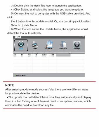
3) Double click the desk Top icon to launch the application.
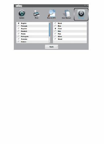
4) Click Setting and select the language you want to update.
5) Connect the tool to computer with the USB cable provided. And
click
the ? button to enter update model. Or, you can simply click select
Setup> Update Mode
6) When the tool enters the Update Mode, the application would
detect the tool automatically.
NOTE
After entering update mode successfully, there are two different ways
for you to update the device.
●The update tool will detect these local files automatically and display
them in a list. Ticking one of them will lead to an update process, which
eliminates the need to download any file.
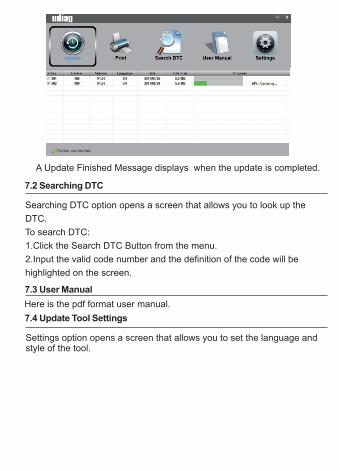
Settings option opens a screen that allows you to set the language and style of the tool.
7.4 Update Tool Settings
A Update Finished Message displays when the update is completed.
7.2 Searching DTC
Searching DTC option opens a screen that allows you to look up the
DTC.
To search DTC:
1.Click the Search DTC Button from the menu.
2.Input the valid code number and the definition of the code will be
highlighted on the screen.
7.3 User Manual
Here is the pdf format user manual.