Embed Size (px)
Citation preview

Burners
LOW NOx Radiant flame burners
RAD-NxT (E3319 rev. 01 - 17/02/2010)

¾¾ In accordance to the internal policy of constant quali-ty improvement, ESA-PYRONICS reserves the right tomodify the technical characteristics of the present docu-ment at any time and without warning.
¾¾ It is possible to download technical sheets whichhave been updated to the latest revision from the www.esapyronics.com website.
¾¾ The RAD-NxT products have been designed, manu-factured and tested according to the most correct con-struction practices and following the applicable require-ments described in UNI EN 746-2-2010 “Industrial hea-ting process equipment - Part 2: Safety requirements forcombustion and for the handling and processing offuels’. We emphasize that the burners described in thisdata sheet are provided as independent units and areexcluded from the scope of the Machine Directive2006/42/EC not having any mobile items that are notexclusively manual.
¾¾ Certified in conformity with the UNI EN ISO 9001Norm by DNV GL.
¾¾ For ESA-PYRONICS, the NxT symbol has the follo-wing two meanings which are connected to each other:
NEXT GENERATION, or new generation burners that
maintain functionality, reliability and performance.
NOx TECHNOLOGY energy saving and low polluting
emissions.
RAD-NxT - E3319 rev. 01 - 17/02/10
www.esapyronics.com 2
GENERAL WARNINGS:
¾¾ All installation, maintenance, ignition and setting mustbe performed by qualified staff, respecting the norms
present at the time and place of the installation.
¾¾ To avoid damage to people and things, it is essentialto observe all the points indicated in this handbook. The
reported indications do not exonerate the Client/User
from observing general or specific laws concerning acci-
dents and environmental safeguarding.
¾¾ The operator must wear proper DPI clothing (shoes,helmets...) and respect the general safety, prevention
and precaution norms.
¾¾ To avoid the risks of burns or high voltage electrocu-tion, the operator must avoid all contact with the burner
and its control devices during the ignition phase and
while it is running at high temperatures.
¾¾ All ordinary and extraordinary maintenance must beperformed when the system is stopped.
¾¾ To assure correct and safe use of the combustionplant, it is of extreme importance that the contents of this
document be brought to the attention of and be meticu-
lously observed by all personnel in charge of controlling
and working the devices.
¾¾ The functioning of a combustion plant can be dange-rous and cause injuries to persons or damage to equip-
ment. Every burner must be provided with certified com-
bustion safety and supervision devices.
¾¾ The burner must be installed correctly to prevent anytype of accidental/undesired heat transmission from the
flame to the operator or the equipment.
¾¾ The performances indicated in this technical docu-ment regarding the range of products are a result of
experimental tests carried out at ESA-PYRONICS. The
tests have been performed using ignition systems, flame
detectors and supervisors developed by ESA-PYRO-
NICS. The respect of the above mentioned functioning
conditions cannot be guaranteed if equipment, which is
not present in the ESA-PYRONICS catalogue, is used.
CONTACTS / SERVICE:
To dispose of the product, abide by the local legislations
regarding it.
DISPOSAL:
ESA S.p.A.
Via Enrico Fermi 40
24035 Curno (BG) - Italy
Tel +39.035.6227411
Fax +39.035.6227499
ESA Belgium
Zoning Industriel, 4ème rue
B-6040 Jumet - Belgium
Tel +32.71.256970
Fax +32.71.256979
www.esapyronics.com
GENERAL NOTES:
CERTIFICATIONS:
The products conform to the requests for the Euroasia market
(Russia, Belarus and Kazakhstan).

RAD-NxT - E3319 rev. 01 - 17/02/10
www.esapyronics.com 3
APPLICATIONS
The RAD-NxT are gas burners for direct heating.These
burners allow for radiant heat transfer without any reper-
cussions caused by the effect of the flame. According to
the size and working conditions, this type of burner can
be supplied for natural gas, LPG or other types of fuels
having different heating capacities (on request). The
RAD-NxT burners guarantee a substantial decrease in
pollutant emissions (CO & NOx) as well as lower con-
sumption compared with traditional burners, thanks to
their design which has been optimized for the use of pre-
heated air up to 500°C.
¾¾Reheat Furnaces.
¾¾Batch Anneal Furnaces.
¾¾Forging Furnaces.
¾¾Continuous Strip Heating Furnaces.
¾¾Drying Ovens.
¾¾Aluminum Melting Furnaces.
¾¾Galvanizing Furnaces.
¾¾Tube Upsetters.
¾¾Glass Bending and Melting.
¾ ¾ Sinter Hoods and Clay Calcining.
CARATTERISTICS
GENERAL:
¾¾Capacity: from 250 to 750 kW
¾¾Functioning with various types of fuel gases:CH4/LPG/Propane/etc.
¾¾Functioning with preheated air: 500°C
¾¾Limit temperature: 1.350°C
¾¾Air and gas pressure to the burner: 50 mbar
¾¾Flow ratio: 1:6
¾¾Flame velocity: 50-60 m/s
¾¾Low CO e NOx.
MATERIAL COMPOSITION:
¾¾Mixer body: Cast iron G25
¾¾Collector: Cast iron G25
¾¾Fixing flange: Cast iron G25
¾¾Refractory block: Refractory cement Tmax=1650°C
¾¾Flame proof tube: AISI304
¾¾Combustion head: AISI310
F3319I03
F3319I04

RAD-NxT - E3319 rev. 01 - 17/02/10
www.esapyronics.com 4
CAPACITY PARAMETERS
DESCRIPTION
The RAD-NxT burner ignition takes place via a high ten-
sion discharge which is created by an electrode, or by a
pilot flame; the detection takes place via UV rays. All the
accessories related to igntion and detection are not inclu-
ModelCapacity
kW (*)
Flame
diameter mm
Flame projection
mmIgnition Detection
RAD-25 250 400 100 PBC-FR/DSE UV-HT
RAD-35 350 500 120 PBC-FR/DSE UV-HT
RAD-45 450 650 150 PBC-FR/DSE UV-HT
RAD-55 550 850 180 PBC-FR/DSE UV-HT
RAD-65 650 1000 200 PBC-FR/DSE UV-HT
RAD-75 750 1200 220 PBC-FR/DSE UV-HT
FLUE GAS RECIRCULATION
COMBUSTION AIR INLET
GAS INLET
D3319I01
ded in the supply. The adoption of flame control systems
is strongly suggested in all the plants operating at tem-
peratures lower than 750°C (Regulation UNI EN746/2).
The flame and diameter projections are approximate and
refer to methane gas, placed in open air, functional in stoi-
chiometric ratio and at nominal capacity.
The RAD-NxT burners are LOW NOx and apply the most
updated technical improvements so as to guarantee low
NOx and CO emissions, remaining however, functional
even at low chamber temperatures, during ignition with
plant still cold. They create a very high heat exchange
between the furnace and the charge, due to the strong
turbulence of the flame and its radiant component.
(*) In the burner capacity, the preheated air enthalpic contribution is not included.

RAD-NxT - E3319 rev. 01 - 17/02/10
www.esapyronics.com 5
ParameterBurner model
RAD-25 RAD-35 RAD-45 RAD-55 RAD-65 RAD-75
Burner capacity (2% O2) [kW] 250 350 450 550 650 750
Comburent air flow [Nm3/h] 275 385 495 605 715 825
Comburent air temperature [°C] 500
Gas flow [Nm3/h] 25 35 45 55 65 75
Burner inlet air pressure [mbar] 50
Burner inlet gas pressure [mbar] 50Maximum power
BURNER PERFOMANCES
¾¾MIN/MAX functioning
¾¾Chamber temperature 1200°C
¾¾NOx < 250 mg/Nm3 [O2 = 2% ref.]
¾¾air temperature: 500°C
MAXIMUM CAPACITY
ParameterBurner model
RAD-25 RAD-35 RAD-45 RAD-55 RAD-65 RAD-75
Burner capacity (2% O2) [kW] 50 70 90 110 130 150
Comburent air flow [Nm3/h] 55 77 99 121 143 165
Comburent air temperature [°C] 500
Gas flow [Nm3/h] 5 7 9 11 13 15
Burner inlet air pressure [mbar] 2
Burner inlet gas pressure [mbar] 2
Min. power
MINIMUM CAPACITY
The flame capacity and characteristics refer to a bur-
ner fed by natural gas (8600kcal/Nm3), placed in a
combustion chamber at zero pressure at sea level
and functional with 10% ecxess air.
RAD-NxT - E3319 rev. 01 - 17/02/10
www.esapyronics.com 6
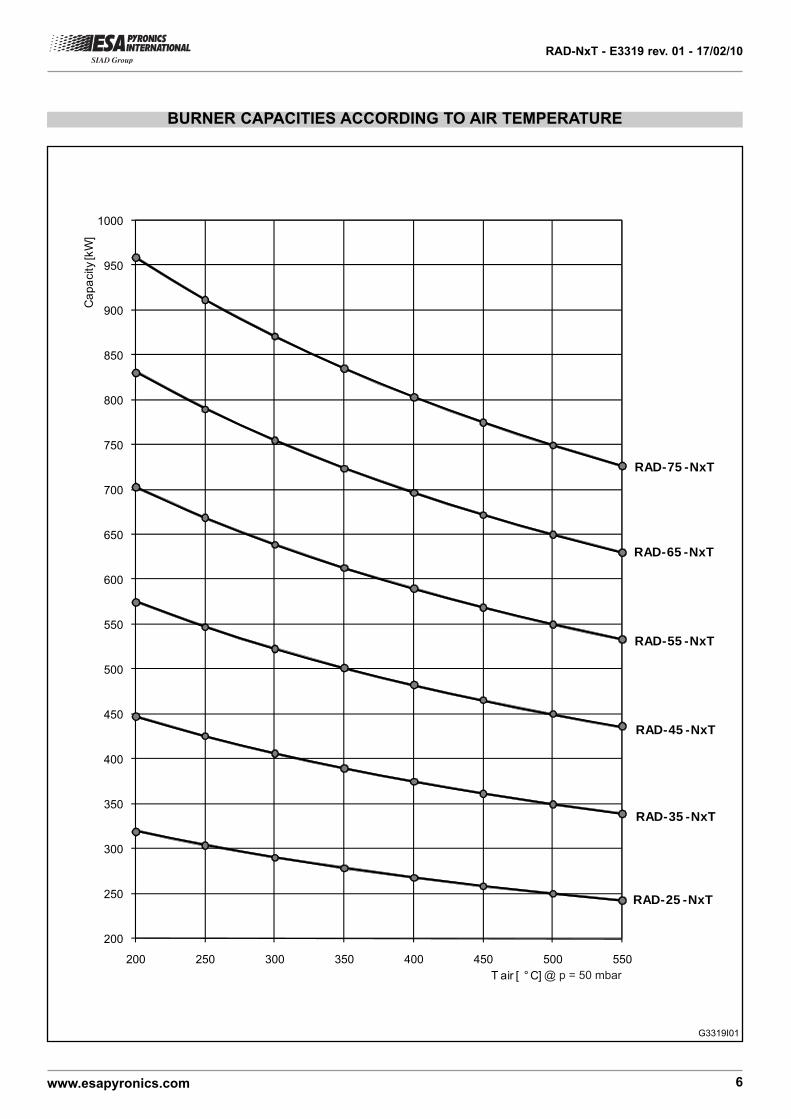
BURNER CAPACITIES ACCORDING TO AIR TEMPERATURE
RAD-25 -NxT
RAD-35 -NxT
RAD-45 -NxT
RAD-65 -NxT
RAD-55 -NxT
RAD-75 -NxT
200
250
300
350
400
450
500
550
600
650
700
750
800
850
900
950
1000
200 250 300 350 400 450 500 550
Ca
pa
city
[kW
]
T air [ ° C] @ p = 50 mbar
G3319I01

RAD-NxT - E3319 rev. 01 - 17/02/10
www.esapyronics.com 7
NOx EMMISSION TABLE
30
40
50
60
70
80
90
100
700 800 900 1000 1100 1200 1300
NO
x [p
pm
] O
2
ref
3%
T furnace [°C]
NOx - Tair=500°C
NOx - Tair=400°C
NOx - Tair=300°C
0
10
20
30
40
50
60
70
80
90
100
700 800 900 1000 1100 1200 1300
NO
x [p
pm
] O
2
ref
3%
°T furnace [ C]
NOx - Tair=500°C
NOx - Tair=400°C
NOx - Tair=300°C
STANDARD FLAME COMBUSTION
ULTRA LOW NOx FLAMELESS COMBUSTION
G3319I03
G3319I02

RAD-NxT - E3319 rev. 01 - 17/02/10
www.esapyronics.com 8
G3319I05
1
10
100
10 100 1000
RA
D-3
5-N
xT
RA
D-2
5-N
xT
RA
D-5
5-N
xT
RA
D-6
5-N
xT
RA
D-7
5-N
xT
RA
D-4
5-N
xT
Total air flow (burner) @ 500 °C P.S.= 1 [Nm3/h]
Burn
er
inle
t gas p
ressure
[m
bar]
CAPACITY CHART
1
10
100
10 100 1000
RA
D-3
5-N
xT
RA
D-2
5-N
xT
RA
D-5
5-N
xT
RA
D-6
5-N
xT
RA
D-7
5-N
xT
RA
D-4
5-N
xT
G3319I04
Natural gas flow @ 20 °C P.S.=0,6 [Nm3/h]
Bu
rne
r in
let
ga
s p
ressu
re [
mb
ar]
RAD-NxT - E3319 rev. 01 - 17/02/10
www.esapyronics.com 9
01
02
06
07
08
03 04
14
05
12
11
10
13
09
15 16
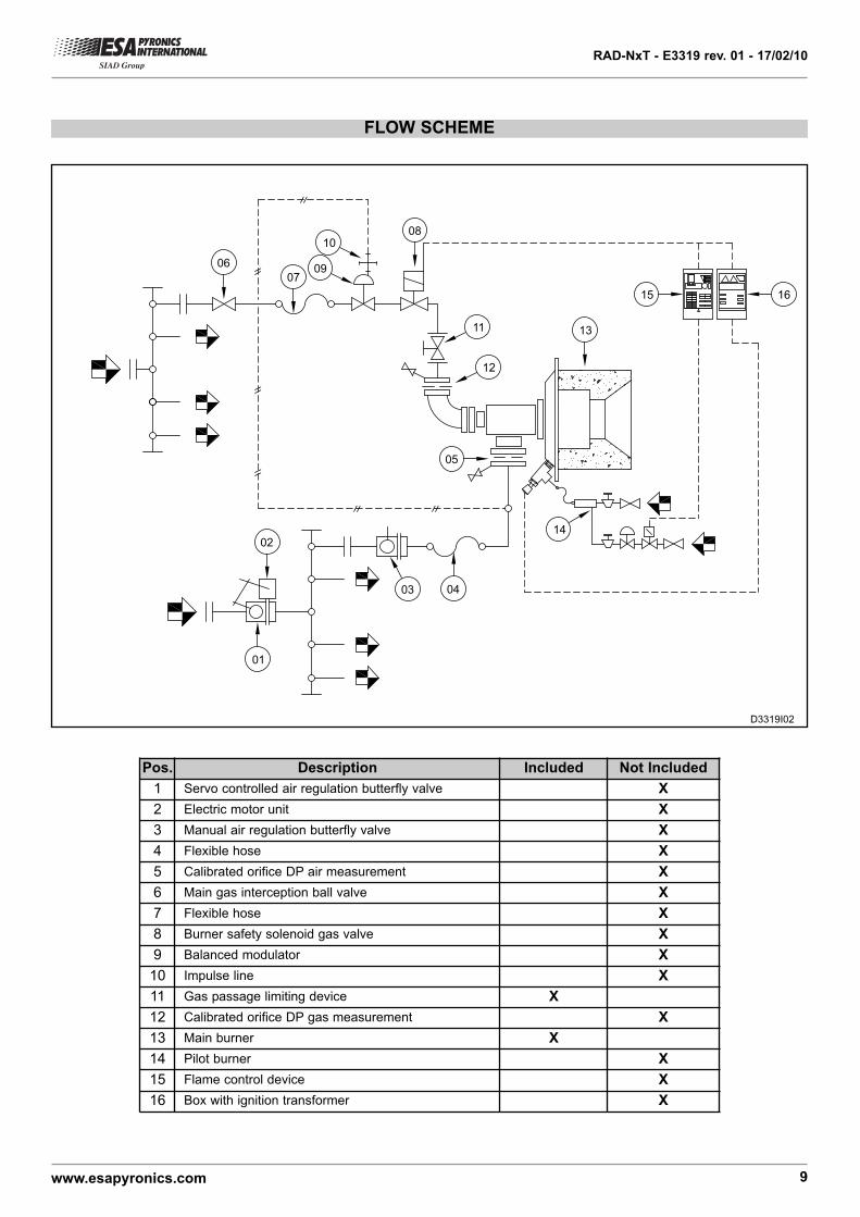
FLOW SCHEME
Pos. Description Included Not Included
1 Servo controlled air regulation butterfly valve X
2 Electric motor unit X
3 Manual air regulation butterfly valve X
4 Flexible hose X
5 Calibrated orifice DP air measurement X
6 Main gas interception ball valve X
7 Flexible hose X
8 Burner safety solenoid gas valve X
9 Balanced modulator X
10 Impulse line X
11 Gas passage limiting device X
12 Calibrated orifice DP gas measurement X
13 Main burner X
14 Pilot burner X
15 Flame control device X
16 Box with ignition transformer X
D3319I02

RAD-NxT - E3319 rev. 01 - 17/02/10
www.esapyronics.com 10
WARNINGS
¾¾ The RAD-NxT burner series are to be used in fixedinstallations. If mobile installations are necessary (bell
furnaces etc...), take into consideration that possible
damage to silicon carbide tubes could be caused due to
the movement of the actual furnace.
¾¾ Burner ignition must always be done at minimumpower, and then modulating towards the maximum, thus
facilitating the ignitions and reducing output overpressu-
res.
¾¾ The passing from minimum to maximum power, andvice versa, must be done gradually and not immediate-
ly.
¾¾ For all applications at low temperatures (upto 750°C),the burner ignition and the fuel gas solenoid valve com-
mands must be carried out using a certified burner con-
trol device.
¾¾ To avoid possible damage to the burners, make surethat the blower does not blow air fouled by combustion
products, oil, solvents or other. To prevent these pheno-
mena from taking place, if possible, install the blower or
suction duct outside of the establishment and far from
the exhaust pipes.
¾¾ Check that the feeding lines are correctly connected
after installation. Before switching on the burner, check
that the comburent air and fuel gas pressures are cor-
rect.
¾¾ If there should be problems with other devices duringthe burner start-up phase, use a connector with anti
disturbance filter to connect the high tension cable to the
ignition electrode.
¾¾ Avoid carrying out burner ignitions too close to eachother, so as not to overheat the ignition system’s com-
mand devices (solenoid valves and tarnsformers).
¾¾ Prewash time lapse + first safety time lapse + min. of5 sec. = time lapse between one ignition and another.
(However, do not attempt more than 2 ignitions during a
30sec. time lapse
¾¾ Make sure the power supply is TURNED OFF whenintervening on the burner and its devices. In case of bur-
ner malfunctioning, follow the indications in the
‘Maintenance’ chapter of the present manual or contact
ESA-PYRONICS assistance.
¾¾ Any modification or repair done by third parties cancompromise the application safety and automatically
cause the general warranty conditions to expire. Contact
ESA-PYRONICS assistance.
INSTALLATION
Place the burner in the appropriate housing on the furna-ce roof, fixing the braces pos.01 and blocking nutspos.02 in the appropriate housings pos.03 created fromthe burner plate.
Adjust the burner height acting on the braces until thebottom part of the refractory block pos.04 is perfectly in
FURNACE ROOF SURFACE
TILE MUST BE FLUSH WITHINTERIOR WALL SURFACE
CERAMIC FIBER FILL(COMPRESSED WITH TAPE)
1
2
3
4
D3319I03
line against the furnace wall. Make sure the burner posi-tion is perfectly flat.
Insert fibre compressed ceramic cuscion with adhesivetape between the block pos.04 and the furnace wall,making sure that no empty spaces are created duringburner installation.

RAD-NxT - E3319 rev. 01 - 17/02/10
www.esapyronics.com 11
IGNITION - SETTING
The procedures indicated in the following chapter must
be carried out by expert technicians. The non-observan-
ce of the instructions given can provoke dangerous con-
ditions.
1 - Check that the blower output combustion air and fuel
gas pressures are within the allowed range.
2 - Regulate the working and intervention pressures of
the combustion plant safety devices, whether there is one
for each burner or just one general device for the whole
combustion plant, such as: gas pressure reducers, block
valve, relief valve, pressure switches, etc. Simulate the
intervention of all the safety devices, including the inter-
vention of the safety overtemperature, checking that all
the fuel block devices react correctly.
3 - Place the motorized air regulation valve in the maxi-
mum opening position and regulate the burner inlet air
pressures, referring to the values indicated in the “Burner
Perfomance” chapter for the maximum potential on page
5.
4 - Place the motorized air regulation valve in the mini-
mum opening position and regulate its opening to obtain
(in burner inlet) the pressures concerning the minimum
power.
5 - Activate the burner control device and attempt igniting
the burner until it switches on. During the ignition
attempts, act on the gas regulation valve and, starting
from the totally closed position, open it gradually until
obtaining burner ignition.
6 - Place the motorized air regulation valve at its maxi-
mum opening and regulate, via the gas regulation valve,
the maximum fuel flow, and if necessary, checking the dif-
ferential pressure created on the calibrated gas flange.
7 - Check again that, at minimum and maximum power,
the burner inlet air pressures correspond to the data indi-
cated in the “CAPACITY PARAMETERS” chapter. They
may differ according to whether the burner is on or off.
8 - If necessary, with all the burners running at the same
power, analyse combustion products in the chamber
(where posssible).
9 - Repeatedly attempt ignition at minimum burner power,
with maximum amplitude, to check the ignition reliability
and the flame stability during regulation.

RAD-NxT - E3319 rev. 01 - 17/02/10
www.esapyronics.com 12
GENERAL MAINTENANCE PLAN
Operation Type Advised time Note
Pilot burner high tension electrode
connectorO annual
Check integrity of outer plastic and oxidi
zation of the internal electrode terminal
Ignition electrode O annual Replace if the Kantal terminal is worn.
Pilot burner O annualCheck settings and ignition electrode
and detection.
Integrirty of refractory block and
internal burner partsE annual
From the inside check that there are no
cracks in the refractory material each time
the plant is switched off for maintenance.
UV scanner glass cleaning O every semesterReduce to quarterly check in dusty envi-
ronments
UV scanner replacement O10.000 h.
of functioningIn any case, every two years.
Gasket replacement on gas side (**) E annual See note.
Burner settings O annualRepeat the steps in the ‘IGNITION AND
SETTING’ chapter.
NOTE:
Key: O = ordinary / E = extraordinary
(*) it is suggested that the gaskets on the gas side are replaced after every disassembly of the gas feeding line.
(**) use high temperature gaskets
RAD-NxT - E3319 rev. 01 - 17/02/10
www.esapyronics.com 13
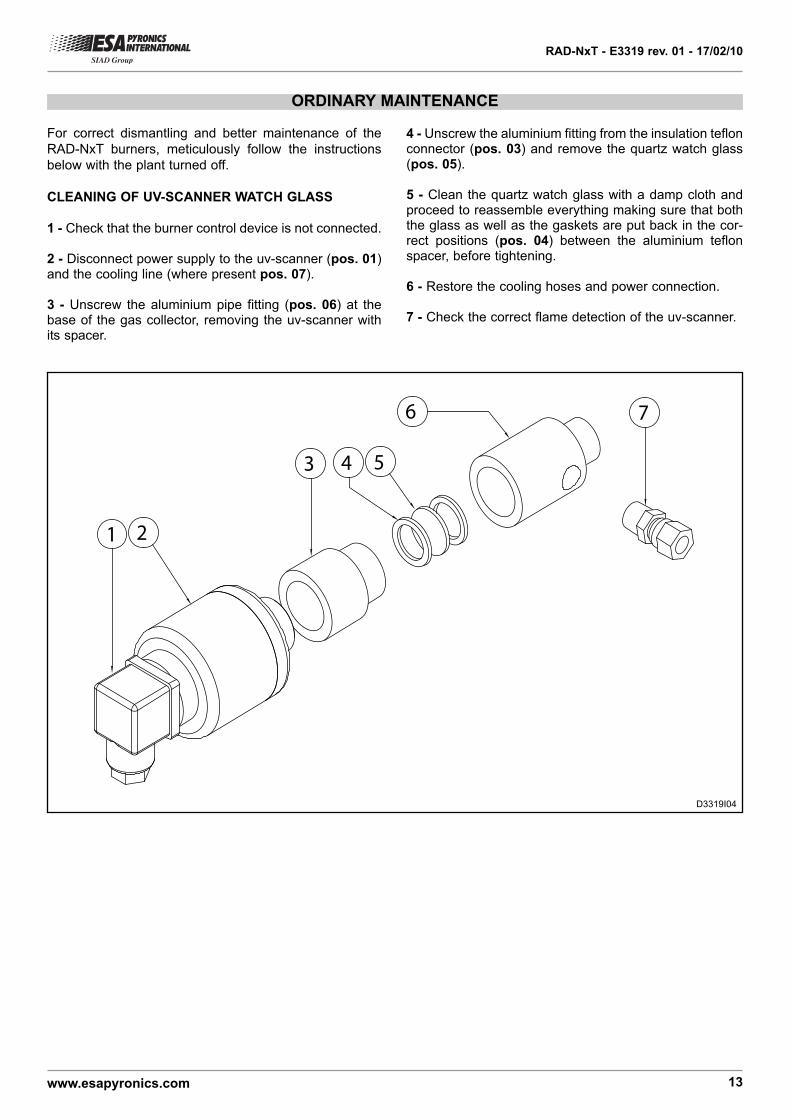
ORDINARY MAINTENANCE
For correct dismantling and better maintenance of the
RAD-NxT burners, meticulously follow the instructions
below with the plant turned off.
CLEANING OF UV-SCANNER WATCH GLASS
1 - Check that the burner control device is not connected.
2 - Disconnect power supply to the uv-scanner (pos. 01)and the cooling line (where present pos. 07).
3 - Unscrew the aluminium pipe fitting (pos. 06) at thebase of the gas collector, removing the uv-scanner withits spacer.
1 2
3 4 5
6 7
4 - Unscrew the aluminium fitting from the insulation teflonconnector (pos. 03) and remove the quartz watch glass(pos. 05).
5 - Clean the quartz watch glass with a damp cloth andproceed to reassemble everything making sure that boththe glass as well as the gaskets are put back in the cor-rect positions (pos. 04) between the aluminium teflonspacer, before tightening.
6 - Restore the cooling hoses and power connection.
7 - Check the correct flame detection of the uv-scanner.
D3319I04

RAD-NxT - E3319 rev. 01 - 17/02/10
www.esapyronics.com 14
For correct dismantling and better maintenance of the
ENM-NxT burners, meticulously follow the instructions
below with the plant turned off.
BURNER IN LOCKOUT
In burner lockout conditions, refer to the burner con-
trol device indications and to the relative manual so
as to idenitfy the cause. Below the main cases are
indicated:
¾¾Illegal flame detection: lockout due to the detection of
an illegal flame during the phases that precede the igni-
tion or following shut off. The causes are to be found in
the detection system (broken probe or presence of humi-
dity), or else in the gas drawn by the safety solenoid
valve which allows the burner to remain on.
EXTRAORDINARY MAINTENANCE
¾¾Ignition failed: lockout due to no flame formation
during start-up. The causes are to be found in the igni-
tion system (no spark, broken or badly positioned elec-
trodes), in the bad regulation of fuel or comburent flow or
in the detection system (broken probe or interrupted
cables). Specifically, in the first two cases, the flame
does not ignite, whilst in the last case, the flame forms
but the burner control device is unable to detect it.
¾¾Flame signal loss: lockout due to flame signal loss
during the normal functioning of the burner. The causes
are to be found in the bad regulation of fuel or comburent
flow (rapid flow variations, regulation out of allowed
range) or in the detection system (broken, dirty, or badly
positioned probes).

RAD-NxT - E3319 rev. 01 - 17/02/10
www.esapyronics.com 15
OVERALL DIMENSIONS - RAD-NxT
Ø530
Nr.4 "U
"slots 18
45°
UV scanner(NOT INCLUDED)Ø"N"
Pilot burner(NOT INCLUDED)
Ø "L""U
" slo
t h
eig
ht
= 43
290
"C"
Ø600
"G""F1"
AIR
IN
LE
T Ø
"A"
GA
S I
NLE
T Ø
"B"
"E"
"D"
"F2"
RAD-NxT-GA version
RAD-NxT-F version
Burner Model øA øB (*)C
mm
D
mm
E
mm
F1
mm
F2
mm
H
mm
Pilot
Socket
ø L
Pilot
ø M
UV
ø N
Mass
Kg
RAD-25-NxT DN100 Rp 1.1/4” 244 469 532 187 149 222 Rp 1” Rp 3/4” Rp 3/4” 299
RAD-35-NxT DN100 Rp 1.1/4” 244 469 532 187 149 222 Rp 1” Rp 3/4” Rp 3/4” 299
RAD-45-NxT DN150 Rp 1.1/2” 244 469 532 187 149 222 Rp 1” Rp 3/4” Rp 3/4” 249
RAD-55-NxT DN150 Rp 1.1/2” 244 469 532 187 149 222 Rp 1” Rp 3/4” Rp 3/4” 249
RAD-65-NxT DN150 Rp 2” 244 469 532 185 147 222 Rp 1” Rp 3/4” Rp 3/4” 249
RAD-75-NxT DN200 Rp 2” 244 469 532 185 147 222 Rp 1” Rp 3/4” Rp 3/4” 249
(*) On request, burner with counter flange type to be welded.
D3319I05

RAD-NxT - E3319 rev. 01 - 17/02/10
www.esapyronics.com 16
ORDERING INITIALS - COMPLETE BURNER
- --- -RAD NxT --
(1) Special applications done according to the gas characteristics.
(2) For ULTRA LOW NOx emissions.
Model
RAD-35-NxT
RAD-45-NxT
RAD-55-NxT
...(see. capacity tab.)
35
45
55
.....
Fuel
Natural gas
LPG
Poor gas (1)
CH4
GPL
GP
Gas adjuster
With gas adjuster
Without gas adjuster
GA
F
Ignition
Pilot
Ignition electrode
Without ignition
P
E
NI
Flanging type
ESA flange
According to client
drawing
E
C
Flame detection
UV - scanner
Without flame detection
UVND
01
01 02 03 04 05 06 07
02
0307
Combustion system
Standard combustion
Flameless combustion
F
FL(2)
06
04
05