Embed Size (px)
Citation preview
ASSEMBLY INSTRUCTIONS
PK009
SPRUNG BOGIE KITHELJAN
CLASS 35 HYMEKPenBits Model Railways
www.penbits.co.uk
c/o 12 Fieldside, Long Wittenham, ABINGDON, Oxon, OX14 4QB

23333334445556679
101114212431343640434649
Table of Contents
Table of ContentsGeneral Notes
A Few Words …SafetyThe Instructions
File FormatStructurePrinting
The EtchesTagsSlotsDegree of EtchingCuspsFolds
SolderingSpring WindingWarranties
Heljan Class 35: HolesHeljan Bo-Bo Locos: Pivot FramesBearing CarriersHeljan Class 35 BolsterHeljan Class 35 SubframeHeljan Hymek: Preparing the LocomotiveHeljan 4-wheel bogies: Fitting WheelsetsHeljan Class 35: Springs, Bogie Assembly and Rolling TestHeljan Class 35: Cosmetic Bogie DetailModifying the Heljan Drive UnitHeljan Class 35: Pickups and PowerHeljan Class 35: Final Assembly
Table of Contents 3/51
(c) PenBits Model Railways, All Rights Reserved 27/09/2021
General NotesA Few Words …SafetyThe Instructions
File FormatStructurePrinting
The EtchesTagsSlotsDegree of EtchingCuspsFolds
SolderingSpring WindingWarranties
A Few Words …These advices, taken, several moons since, from John Lythgoe's instructions for his FormilModel Engineering Dyna-drive kits, have proved to be useful and enduring tenets:
"Proceed with patience and due care at ALL stages and a free-running locomotiveshould result.""Allow sufficient time to spread the conversion over a number of modelling sessions.""Work in good light conditions. Use an anglepoise-type lamp if possible. A self-supported magnifier is a useful aid."
SafetyOur kits are intended to be assembled by adult modellers, with some workshop experienceand awareness, who are able to exercise due care and attention when handling thematerials and carrying out the various operations involved. Many of the metal componentshave sharp edges. Chemical products used in assembly can be injurious through contactwith skin or eyes, ingestion or inhalation. Some processes involve high temperatures. Theuser should be aware of and follow the manufacturers' or suppliers' safety data andinstructions for all tools, materials and products.
The Instructions
File Format
The instructions are available on line in both HTML and pdf formats. The HTMLversions have one page for each major section, whilst the pdf versions have a
single file for each kit.
Structure
General Notes 4/51
(c) PenBits Model Railways, All Rights Reserved 27/09/2021
We've divided up the instructions into "narrative" paragraphs, like this one, whichindicate what is being accomplished by a particular stage,
"instruction" paragraphs, like this one, with the tick-box; "box-ticking" not ourfavourite activity perhaps but nonetheless can be useful, on a printed copy, for
recording progress and making sure nothing is forgotten,
and "advisory" paragraphs, like this one, which pass on techniques that we founduseful but aren't necessarily the best way, or the only way, of achieving a result.
Printing
We have introduced a "Check List" for some of the kits, which contains the texts ofall the instruction paragraphs for the kit. This is a great deal more compact for
printing than the full instructions, and perhaps more suitable for the workshop. The CheckLists are available only from the on-line copy of the instructions, from this Index Page.
We intend the Full Instructions to be viewed 'on-screen'. If you did need any of thediagrams or pictures in the workshop, you could download and print them individually
(from the HTML instruction pages) to complement the Check List.
The pdf files can be printed in full or in parts to your own printer using your pdfviewer. Full printouts in booklet form can also be produced using third party services.
For more information visit our Printing the pdf Files page.
If you wish to print out sections of the HTML instructions, they are formatted instandard HTML/CSS but, even so, the print function in some browsers does a better
job of rendering them than others. We find that 'Print' function of the Google Chromebrowser produces a good printed result: it also gives the option of 'Save as PDF', which isa convenient way of creating a single portable file, including all the illustrations, which youcan view or print on any device.
If your printer can produce half-size A5 prints (two per A4 sheet) or, better still,double-sided A5 booklet printing, using those options can save a great deal of paper.
The Etches
Tags
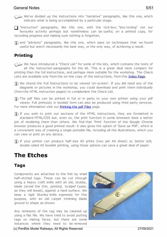
Components are attached to the fret by smallhalf-etched tags. These can be cut throughusing a heavy craft knife with an old, stubby,blade (avoid the thin, pointed, 'scalpel' types,as they will break), against a hard surface. Wekeep a rigid Stanley knife expressly for thispurpose, with an old carpet trimming bladeground to shape as shown.
Any remnants of the tag may be cleaned upusing a flat file. We have tried to avoid puttingtags on mating faces, but there are someinstances where they need to be removed
General Notes 5/51
(c) PenBits Model Railways, All Rights Reserved 27/09/2021
thoroughly.
Slots
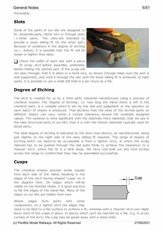
Some of the parts of our kits are designed tofit, perpendicularly, either into or through slotsi n other parts. The slots are intended toprovide a loose sliding fit for the other part.Because of variations in the degree of etching(q.v., below), it is possible that the fit will belooser or tighter than ideal.
Check the width of each slot with a pieceof scrap etch before assembly, preferably
before folding the slotted part. If the scrap willnot pass through, hold it in pliers or a hand vice, as shown (though make sure the part iswell supported), and work it through the slot until the loose sliding fit is achieved. In tightspots, it is possible to use a small drill held in a pin chuck as a file.
Degree of Etching
The etch is created for us by a third party industrial manufacturer using a process ofchemical erosion. The 'Degree of Etching', i.e. how long the metal sheet is left in thechemical bath, is a variable which is set by the skill and judgement of the operator aseach batch of sheets is produced. That dictates that the sizes of the etched parts ondifferent sheets can vary, within a certain tolerance, around the nominally designedvalues. The variation is more significant with the relatively thick materials, that we use inthe main structural parts of our kits, than it is with the thinner materials typically used fordetail parts.
The ideal degree of etching is indicated by the slots (see above), as manufactured, beingjust slightly on the tight side of the easy sliding fit required. The range of degree ofetching which we deem to be acceptable is from a 'lighter' etch, in which the scrapmaterial has to be pushed through the slot quite firmly to achieve the clearance, to a'heavier' etch, where the fit is a little loose. We have test built our kits from etchesacross this range to confirm that they may be assembled successfully.
Cusps
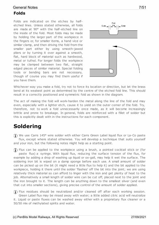
The chemical erosion process works equallyfrom each side of the metal, resulting in theedges of the etch having shaped 'cusps' as inthe diagram here. On edges which will bevisible on the finished model, it is good practiceto file the edges of the metal flat. Many of theedges on our kits are hidden from view.
Where edges form joints with othercomponents, on a 'lighter' etch the edges mayneed to be filed to a flat surface to achieve a fit, whereas with a 'heavier' etch one mightleave more of the cusps in place. In places which can't be reached by a file, e.g. in acutecorners of the etch, the cusp may be pared away with a sharp knife.
General Notes 6/51
(c) PenBits Model Railways, All Rights Reserved 27/09/2021
Folds
Folds are indicated on the etches by half-etched lines. Unless stated otherwise, all foldsare made at 90° with the half-etched line onthe inside of the fold. Most folds may be madeby holding the larger part of the workpiece inthe fingers or, for smaller items, a hand vice orsimilar clamp, and then driving the fold from thesmaller part either by using smooth-jawedpliers or by turning it over against a smooth,flat, hard block of material such as hardwood,metal or tufnol. For longer folds the workpiecemay be clamped between two flat, straightedged pieces of similar material. Special foldingtools or bending bars are not necessary,though of course you may find them useful ifyou have them.
Whichever way you make a fold, try not to force its location or direction, but let the brassbend at its weakest point as determined by the centre of the etched fold line. This shouldresult in a correctly positioned and symmetric fold as shown in the diagram.
The act of making the fold will work-harden the metal along the line of the fold and mayeven, especially with a lighter etch, cause it to yield on the outer corner of the fold. Try,therefore, not to work a fold unnecessarily once made, as it will become increasinglybrittle and prone to breakage. In general, folds are reinforced with a fillet of solder butthis is explicitly dealt with in the instructions for each component.
SolderingWe use Carrs 145° wire solder with either Carrs Green Label liquid flux or La-Co pasteflux, except where stated otherwise. You will develop a technique that suits yourself
and your iron, but the following notes might help as a starting point.
Flux can be applied to the workpiece using a brush, a pointed cocktail stick or (forpaste flux) a syringe. With liquid flux, reducing the surface tension of the flux, for
example by adding a drop of washing up liquid or ox-gall, may help it wet the surface. Thesoldering iron bit is wiped on a damp sponge before each use. A small amount of soldercan be picked up on the bit (it might need a little flux to help it) and the bit applied to theworkpiece, holding it there until the solder 'flashes' off the bit into the joint; we are usingrelatively thick material so can afford to linger with the iron and get plenty of heat to thejob. Alternatively a small length of solder wire can be cut off, placed next to the joint andthe iron brought to it. The length can be anything down to the smallest sliver (and eventhat cut into smaller sections), giving precise control of the amount of solder applied.
Flux residues should be neutralized and/or cleaned off after each working session.Green Label flux may be rinsed away with water; a little added citric acid will neutralize
it. Liquid or paste fluxes can be washed away either with a proprietary flux cleaner or a50/50 mix of methylated spirits and water.
General Notes 7/51
(c) PenBits Model Railways, All Rights Reserved 27/09/2021
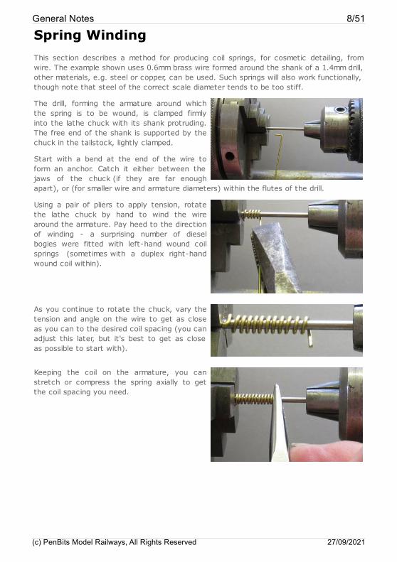
Spring WindingThis section describes a method for producing coil springs, for cosmetic detailing, fromwire. The example shown uses 0.6mm brass wire formed around the shank of a 1.4mm drill,other materials, e.g. steel or copper, can be used. Such springs will also work functionally,though note that steel of the correct scale diameter tends to be too stiff.
The drill, forming the armature around whichthe spring is to be wound, is clamped firmlyinto the lathe chuck with its shank protruding.The free end of the shank is supported by thechuck in the tailstock, lightly clamped.
Start with a bend at the end of the wire toform an anchor. Catch it either between thejaws of the chuck (if they are far enoughapart), or (for smaller wire and armature diameters) within the flutes of the drill.
Using a pair of pliers to apply tension, rotatethe lathe chuck by hand to wind the wirearound the armature. Pay heed to the directionof winding - a surprising number of dieselbogies were fitted with left-hand wound coilsprings (sometimes with a duplex right-handwound coil within).
As you continue to rotate the chuck, vary thetension and angle on the wire to get as closeas you can to the desired coil spacing (you canadjust this later, but it's best to get as closeas possible to start with).
Keeping the coil on the armature, you canstretch or compress the spring axially to getthe coil spacing you need.
General Notes 8/51
(c) PenBits Model Railways, All Rights Reserved 27/09/2021
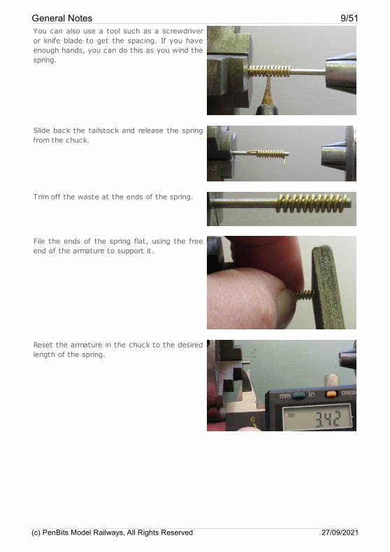
You can also use a tool such as a screwdriveror knife blade to get the spacing. If you haveenough hands, you can do this as you wind thespring.
Slide back the tailstock and release the springfrom the chuck.
Trim off the waste at the ends of the spring.
File the ends of the spring flat, using the freeend of the armature to support it.
Reset the armature in the chuck to the desiredlength of the spring.
General Notes 9/51
(c) PenBits Model Railways, All Rights Reserved 27/09/2021

Cut the spring slightly overlength and file thecut end flat using the armature as a supportand length gauge.
Little beauties. Results improve with practice -all very therapeutic!
WarrantiesThe procedures described in our instructions require the proprietary locomotive to bedismantled and some of its components to be modified. The manufacturer's warranty willalmost certainly be rendered void by carrying out the modifications. The user shouldensure that the locomotive is free running and has no warranty issues before commencingwork.
Please follow the manufacturer's instructions for the dismantling of the locomotive.
Our instructions guide you in making modifications to components of the locomotive andfitting the kit. The modifications, the kit and the instructions have been tested by the kitdesigner and others to confirm that they are practical, serviceable and, when used asintended, produce a working locomotive whose performance will bring much pleasure.However, as the fitting of the kit by the user is out of our direct control, we can make nowarranty, expressed or implied, as to the performance and continued serviceability of thelocomotive following modification.
General Notes 10/51
(c) PenBits Model Railways, All Rights Reserved 27/09/2021
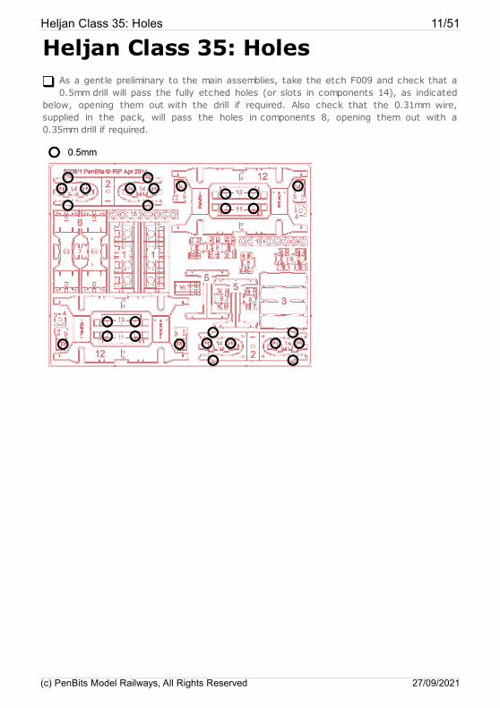
Heljan Class 35: HolesAs a gentle preliminary to the main assemblies, take the etch F009 and check that a0.5mm drill will pass the fully etched holes (or slots in components 14), as indicated
below, opening them out with the drill if required. Also check that the 0.31mm wire,supplied in the pack, will pass the holes in components 8, opening them out with a0.35mm drill if required.
Heljan Class 35: Holes 11/51
(c) PenBits Model Railways, All Rights Reserved 27/09/2021
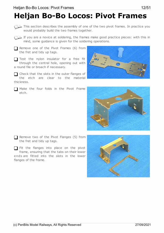
Heljan Bo-Bo Locos: Pivot FramesThis section describes the assembly of one of the two pivot frames. In practice youwould probably build the two frames together.
If you are a novice at soldering, the frames make good practice pieces: with this inmind, some guidance is given for the soldering operations.
Remove one of the Pivot Frames (6) fromthe fret and tidy up tags.
Test the nylon insulator for a free fitthrough the central hole, opening out with
a round file or broach if necessary.
Check that the slots in the outer flanges ofthe etch are clear to the material
thickness.
Make the four folds in the Pivot Frameetch.
Remove two of the Pivot Flanges (5) fromthe fret and tidy up tags.
Fit the flanges into place on the pivotframe, ensuring that the tabs on their lower
ends are fitted into the slots in the lowerflanges of the frame.
Heljan Bo-Bo Locos: Pivot Frames 12/51
(c) PenBits Model Railways, All Rights Reserved 27/09/2021
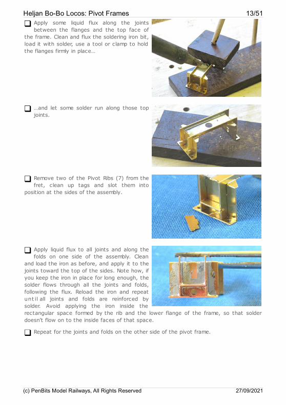
Apply some liquid flux along the jointsbetween the flanges and the top face of
the frame. Clean and flux the soldering iron bit,load it with solder, use a tool or clamp to holdthe flanges firmly in place…
…and let some solder run along those topjoints.
Remove two of the Pivot Ribs (7) from thefret, clean up tags and slot them into
position at the sides of the assembly.
Apply liquid flux to all joints and along thefolds on one side of the assembly. Clean
and load the iron as before, and apply it to thejoints toward the top of the sides. Note how, ifyou keep the iron in place for long enough, thesolder flows through all the joints and folds,following the flux. Reload the iron and repeatunt il all joints and folds are reinforced bysolder. Avoid applying the iron inside therectangular space formed by the rib and the lower flange of the frame, so that solderdoesn't flow on to the inside faces of that space.
Repeat for the joints and folds on the other side of the pivot frame.
Heljan Bo-Bo Locos: Pivot Frames 13/51
(c) PenBits Model Railways, All Rights Reserved 27/09/2021
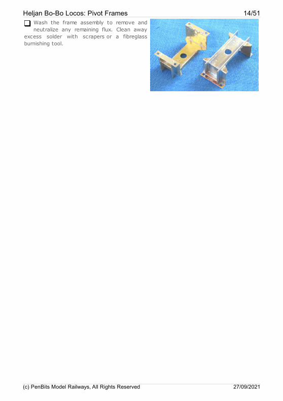
Wash the frame assembly to remove andneutralize any remaining flux. Clean away
excess solder with scrapers or a fibreglassburnishing tool.
Heljan Bo-Bo Locos: Pivot Frames 14/51
(c) PenBits Model Railways, All Rights Reserved 27/09/2021
Bearing CarriersThis stage of the assembly is fixing the subframe bearings into the bearing carriersand folding up the carriers around the bearings. The carriers are located on the fret
in two frames, each of which folds up into a jig to help to fix the bearings in the correctplace. The carriers are a little fiddly, but worth spending time to get right as they are oneof the main functional parts of the suspension.
We find it useful to use two containers to store separately the components of eachbogie; 1kg margarine tubs, for example. Within them we have 35mm film cannisters,
one for each axle, to keep the components for each wheelset together. We mark thecontainers and cannisters to match the id marks etched on to the subframes, bolsters andbearing carriers as explained below.
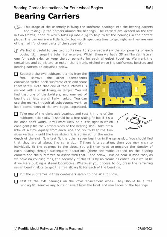
Separate the two subframe etches from thefret. Remove the other components
contained within each subframe etch and storethem safely. Note that one of the subframes ismarked with a small triangular dimple. You willfind that one of the bolsters, and one set ofbearing carriers, are similarly marked. You canuse the marks, through all subsequent work, tokeep components of the two bogies separated.
Take one of the eight axle bearings and test it in one of thesubframe axle slots. It should be a free sliding fit but if it's a
bit loose don't worry. It will more likely be a little tight in whichcase gently file the vertical sides of the bearing slot - take off alittle at a time equally from each side and try to keep the twosides vertical - until the free sliding fit is achieved for the entiredepth of the slot. Now test fit the other seven bearings in the same slot. You should findthat they are all about the same size. If there is a variation, then you may wish toindividually fit the bearings to the slots. You will then need to preserve the identity ofeach bearing through subsequent operations (there are marks etched on the bearingcarriers and the subframes to assist with that - see below). But do bear in mind that, aswe have no coupling rods, the accuracy of this fit is by no means as critical as it would beif we were building a steam locomotive. Whatever you choose to do, dress the remainingseven bearing slots to get the free sliding fit for each of the bearings.
Put the subframes in their containers safely to one side for now.
Test fit the axle bearings on the 2mm replacement axles. They should be a freerunning fit. Remove any burrs or swarf from the front and rear faces of the bearings.
Bearing Carrier Instructions for Four-wheel Bogies 15/51
(c) PenBits Model Railways, All Rights Reserved 27/09/2021
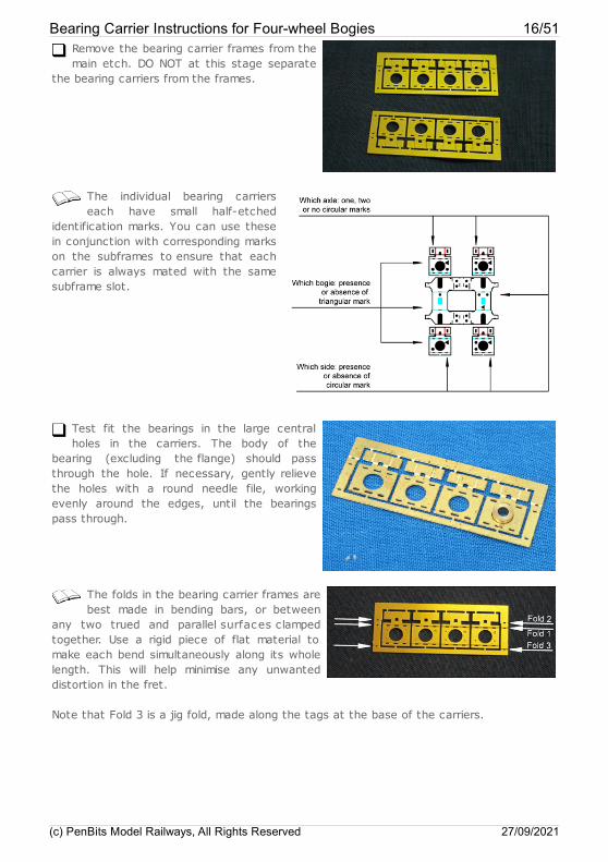
Remove the bearing carrier frames from themain etch. DO NOT at this stage separate
the bearing carriers from the frames.
The individual bearing carrierseach have small half-etched
identification marks. You can use thesein conjunction with corresponding markson the subframes to ensure that eachcarrier is always mated with the samesubframe slot.
Test fit the bearings in the large centralholes in the carriers. The body of the
bearing (excluding the flange) should passthrough the hole. If necessary, gently relievethe holes with a round needle file, workingevenly around the edges, until the bearingspass through.
The folds in the bearing carrier frames arebest made in bending bars, or between
any two trued and parallel surfaces clampedtogether. Use a rigid piece of flat material tomake each bend simultaneously along its wholelength. This will help minimise any unwanteddistortion in the fret.
Note that Fold 3 is a jig fold, made along the tags at the base of the carriers.
Bearing Carrier Instructions for Four-wheel Bogies 16/51
(c) PenBits Model Railways, All Rights Reserved 27/09/2021
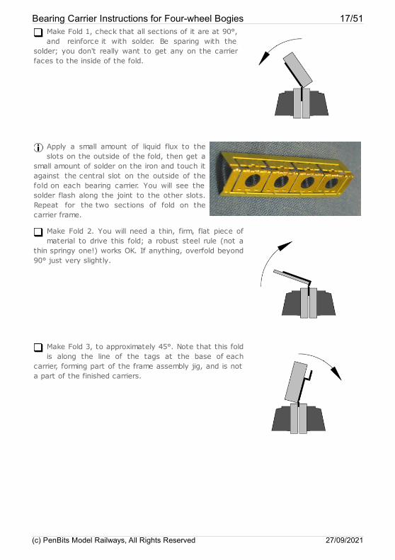
Make Fold 1, check that all sections of it are at 90°,and reinforce it with solder. Be sparing with the
solder; you don't really want to get any on the carrierfaces to the inside of the fold.
Apply a small amount of liquid flux to theslots on the outside of the fold, then get a
small amount of solder on the iron and touch itagainst the central slot on the outside of thefold on each bearing carrier. You will see thesolder flash along the joint to the other slots.Repeat for the two sections of fold on thecarrier frame.
Make Fold 2. You will need a thin, firm, flat piece ofmaterial to drive this fold; a robust steel rule (not a
thin springy one!) works OK. If anything, overfold beyond90° just very slightly.
Make Fold 3, to approximately 45°. Note that this foldis along the line of the tags at the base of each
carrier, forming part of the frame assembly jig, and is nota part of the finished carriers.
Bearing Carrier Instructions for Four-wheel Bogies 17/51
(c) PenBits Model Railways, All Rights Reserved 27/09/2021
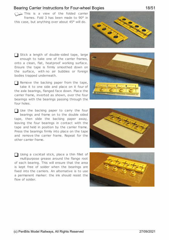
This is a view of the folded carrierframes. Fold 3 has been made to 90° in
this case, but anything over about 45° will do.
Stick a length of double-sided tape, largeenough to take one of the carrier frames,
onto a clean, flat, heatproof working surface.Ensure the tape is firmly smoothed down onthe surface, with no air bubbles or foreignbodies trapped underneath.
Remove the backing paper from the tape,take it to one side and place on it four of
the axle bearings, flanged face down. Place thecarrier frame, inverted as shown, over the fourbearings with the bearings passing through thefour holes.
Use the backing paper to carry the fourbearings and frame on to the double sided
tape, then slide the backing paper away,leaving the four bearings in contact with thetape and held in position by the carrier frame.Press the bearings firmly into place on the tapeand remove the carrier frame. Repeat for theother carrier frame.
Using a cocktail stick, place a thin fillet ofmultipurpose grease around the flange root
of each bearing. This will ensure that the areais kept free of solder when the bearings arefixed into the carriers. An alternative is to usea permanent marker: the ink should resist theflow of solder.
Bearing Carrier Instructions for Four-wheel Bogies 18/51
(c) PenBits Model Railways, All Rights Reserved 27/09/2021
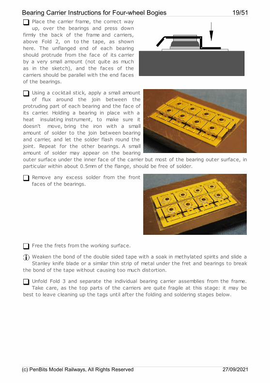
Place the carrier frame, the correct wayup, over the bearings and press down
firmly the back of the frame and carriers,above Fold 2, on to the tape, as shownhere. The unflanged end of each bearingshould protrude from the face of its carrierby a very small amount (not quite as muchas in the sketch), and the faces of thecarriers should be parallel with the end facesof the bearings.
Using a cocktail stick, apply a small amountof flux around the join between the
protruding part of each bearing and the face ofits carrier. Holding a bearing in place with aheat insulating instrument, to make sure itdoesn't move, bring the iron with a smallamount of solder to the join between bearingand carrier, and let the solder flash round thejoint. Repeat for the other bearings. A smallamount of solder may appear on the bearingouter surface under the inner face of the carrier but most of the bearing outer surface, inparticular within about 0.5mm of the flange, should be free of solder.
Remove any excess solder from the frontfaces of the bearings.
Free the frets from the working surface.
Weaken the bond of the double sided tape with a soak in methylated spirits and slide aStanley knife blade or a similar thin strip of metal under the fret and bearings to break
the bond of the tape without causing too much distortion.
Unfold Fold 3 and separate the individual bearing carrier assemblies from the frame.Take care, as the top parts of the carriers are quite fragile at this stage: it may be
best to leave cleaning up the tags until after the folding and soldering stages below.
Bearing Carrier Instructions for Four-wheel Bogies 19/51
(c) PenBits Model Railways, All Rights Reserved 27/09/2021
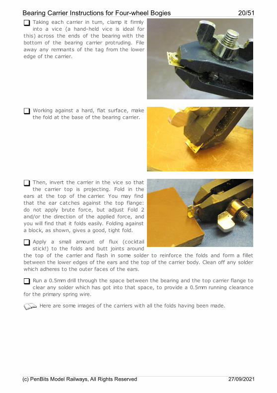
Taking each carrier in turn, clamp it firmlyinto a vice (a hand-held vice is ideal for
this) across the ends of the bearing with thebottom of the bearing carrier protruding. Fileaway any remnants of the tag from the loweredge of the carrier.
Working against a hard, flat surface, makethe fold at the base of the bearing carrier.
Then, invert the carrier in the vice so thatthe carrier top is projecting. Fold in the
ears at the top of the carrier. You may findthat the ear catches against the top flange:do not apply brute force, but adjust Fold 2and/or the direction of the applied force, andyou will find that it folds easily. Folding againsta block, as shown, gives a good, tight fold.
Apply a small amount of flux (cocktailstick!) to the folds and butt joints around
the top of the carrier and flash in some solder to reinforce the folds and form a filletbetween the lower edges of the ears and the top of the carrier body. Clean off any solderwhich adheres to the outer faces of the ears.
Run a 0.5mm drill through the space between the bearing and the top carrier flange toclear any solder which has got into that space, to provide a 0.5mm running clearance
for the primary spring wire.
Here are some images of the carriers with all the folds having been made.
Bearing Carrier Instructions for Four-wheel Bogies 20/51
(c) PenBits Model Railways, All Rights Reserved 27/09/2021
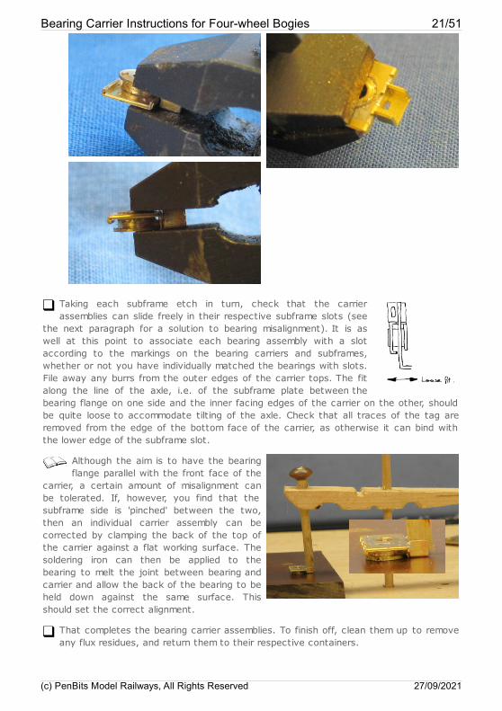
Taking each subframe etch in turn, check that the carrierassemblies can slide freely in their respective subframe slots (see
the next paragraph for a solution to bearing misalignment). It is aswell at this point to associate each bearing assembly with a slotaccording to the markings on the bearing carriers and subframes,whether or not you have individually matched the bearings with slots.File away any burrs from the outer edges of the carrier tops. The fitalong the line of the axle, i.e. of the subframe plate between thebearing flange on one side and the inner facing edges of the carrier on the other, shouldbe quite loose to accommodate tilting of the axle. Check that all traces of the tag areremoved from the edge of the bottom face of the carrier, as otherwise it can bind withthe lower edge of the subframe slot.
Although the aim is to have the bearingflange parallel with the front face of the
carrier, a certain amount of misalignment canbe tolerated. If, however, you find that thesubframe side is 'pinched' between the two,then an individual carrier assembly can becorrected by clamping the back of the top ofthe carrier against a flat working surface. Thesoldering iron can then be applied to thebearing to melt the joint between bearing andcarrier and allow the back of the bearing to beheld down against the same surface. Thisshould set the correct alignment.
That completes the bearing carrier assemblies. To finish off, clean them up to removeany flux residues, and return them to their respective containers.
Bearing Carrier Instructions for Four-wheel Bogies 21/51
(c) PenBits Model Railways, All Rights Reserved 27/09/2021
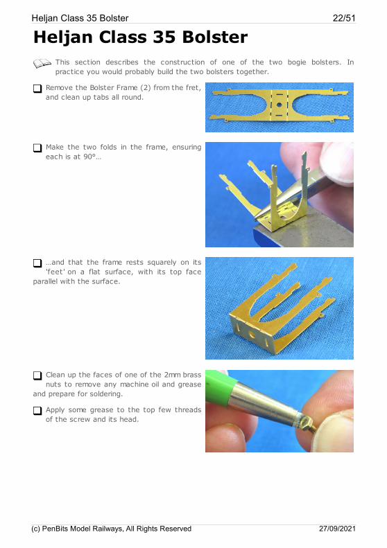
Heljan Class 35 BolsterThis section describes the construction of one of the two bogie bolsters. Inpractice you would probably build the two bolsters together.
Remove the Bolster Frame (2) from the fret,and clean up tabs all round.
Make the two folds in the frame, ensuringeach is at 90°…
…and that the frame rests squarely on its'feet ' on a flat surface, with its top face
parallel with the surface.
Clean up the faces of one of the 2mm brassnuts to remove any machine oil and grease
and prepare for soldering.
Apply some grease to the top few threadsof the screw and its head.
Heljan Class 35 Bolster 22/51
(c) PenBits Model Railways, All Rights Reserved 27/09/2021
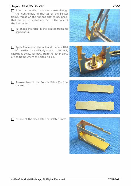
From the outside, pass the screw throughthe central hole in the top of the bolster
frame, thread on the nut and tighten up. Checkthat the nut is central and flat to the face ofthe bolster top.
Re-check the folds in the bolster frame forsquareness.
Apply flux around the nut and run in a filletof solder immediately around the nut,
keeping it away, for now, from the outer partsof the frame where the sides will go.
Remove two of the Bolster Sides (3) fromthe fret.
Fit one of the sides into the bolster frame…
Heljan Class 35 Bolster 23/51
(c) PenBits Model Railways, All Rights Reserved 27/09/2021
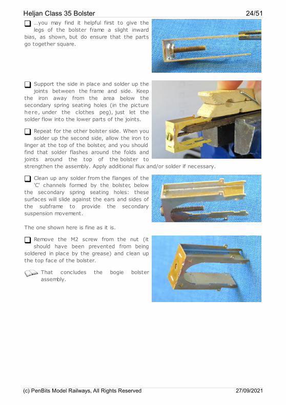
…you may find it helpful first to give thelegs of the bolster frame a slight inward
bias, as shown, but do ensure that the partsgo together square.
Support the side in place and solder up thejoints between the frame and side. Keep
the iron away from the area below thesecondary spring seating holes (in the picturehere, under the clothes peg), just let thesolder flow into the lower parts of the joints.
Repeat for the other bolster side. When yousolder up the second side, allow the iron to
linger at the top of the bolster, and you shouldfind that solder flashes around the folds andjoints around the top of the bolster tostrengthen the assembly. Apply additional flux and/or solder if necessary.
Clean up any solder from the flanges of the'C' channels formed by the bolster, below
the secondary spring seating holes: thesesurfaces will slide against the ears and sides ofthe subframe to provide the secondarysuspension movement.
The one shown here is fine as it is.
Remove the M2 screw from the nut (itshould have been prevented from being
soldered in place by the grease) and clean upthe top face of the bolster.
That concludes the bogie bolsterassembly.
Heljan Class 35 Bolster 24/51
(c) PenBits Model Railways, All Rights Reserved 27/09/2021
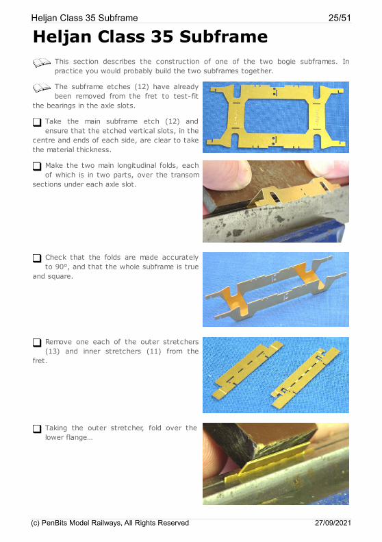
Heljan Class 35 SubframeThis section describes the construction of one of the two bogie subframes. Inpractice you would probably build the two subframes together.
The subframe etches (12) have alreadybeen removed from the fret to test-fit
the bearings in the axle slots.
Take the main subframe etch (12) andensure that the etched vertical slots, in the
centre and ends of each side, are clear to takethe material thickness.
Make the two main longitudinal folds, eachof which is in two parts, over the transom
sections under each axle slot.
Check that the folds are made accuratelyto 90°, and that the whole subframe is true
and square.
Remove one each of the outer stretchers(13) and inner stretchers (11) from the
fret.
Taking the outer stretcher, fold over thelower flange…
Heljan Class 35 Subframe 25/51
(c) PenBits Model Railways, All Rights Reserved 27/09/2021
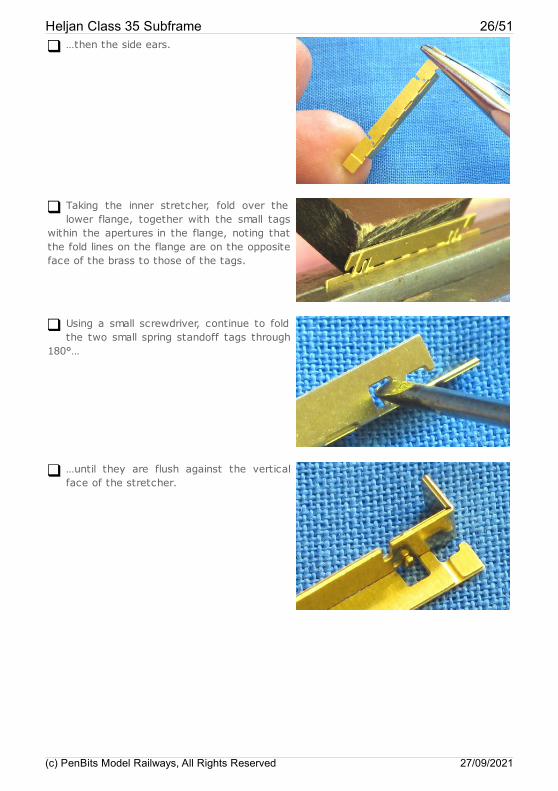
…then the side ears.
Taking the inner stretcher, fold over thelower flange, together with the small tags
within the apertures in the flange, noting thatthe fold lines on the flange are on the oppositeface of the brass to those of the tags.
Using a small screwdriver, continue to foldthe two small spring standoff tags through
180°…
…until they are flush against the verticalface of the stretcher.
Heljan Class 35 Subframe 26/51
(c) PenBits Model Railways, All Rights Reserved 27/09/2021
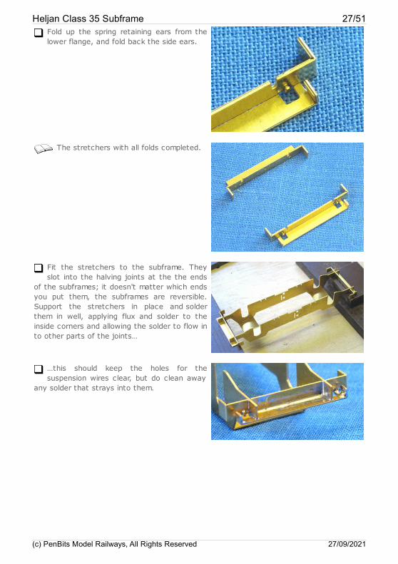
Fold up the spring retaining ears from thelower flange, and fold back the side ears.
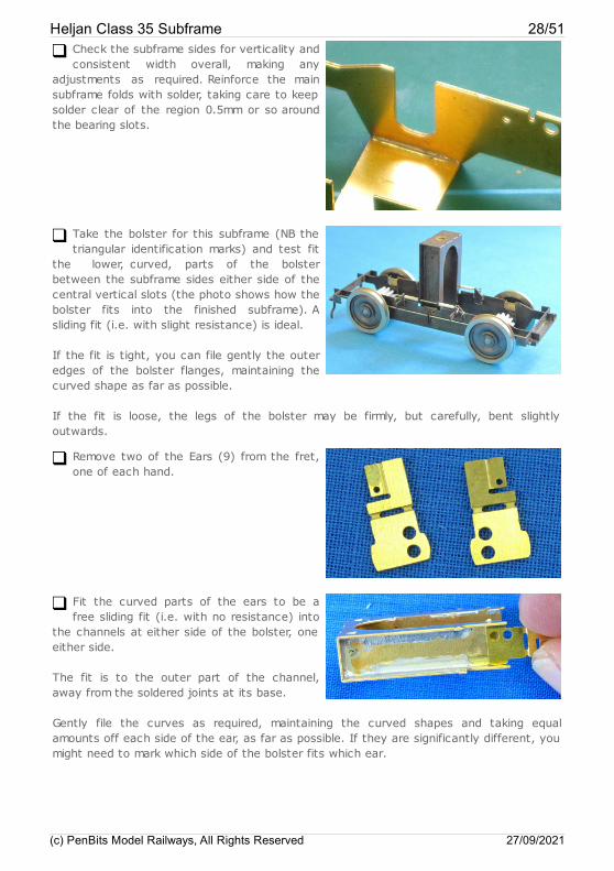
The stretchers with all folds completed.
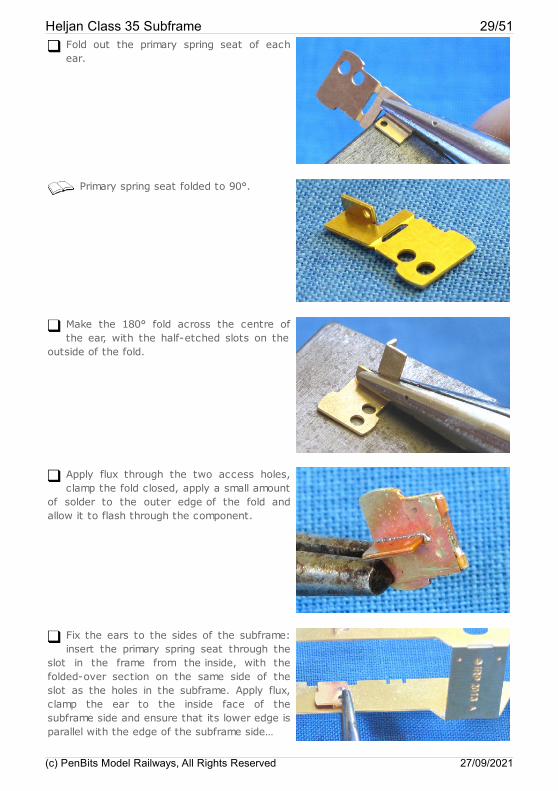
Fit the stretchers to the subframe. Theyslot into the halving joints at the the ends
of the subframes; it doesn't matter which endsyou put them, the subframes are reversible.Support the stretchers in place and solderthem in well, applying flux and solder to theinside corners and allowing the solder to flow into other parts of the joints…
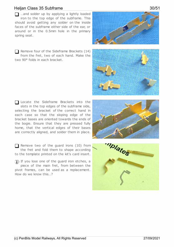
…this should keep the holes for thesuspension wires clear, but do clean away
any solder that strays into them.
Heljan Class 35 Subframe 27/51
(c) PenBits Model Railways, All Rights Reserved 27/09/2021
Check the subframe sides for verticality andconsistent width overall, making any
adjustments as required. Reinforce the mainsubframe folds with solder, taking care to keepsolder clear of the region 0.5mm or so aroundthe bearing slots.
Take the bolster for this subframe (NB thetriangular identification marks) and test fit
the lower, curved, parts of the bolsterbetween the subframe sides either side of thecentral vertical slots (the photo shows how thebolster fits into the finished subframe). Asliding fit (i.e. with slight resistance) is ideal.
If the fit is tight, you can file gently the outeredges of the bolster flanges, maintaining thecurved shape as far as possible.
If the fit is loose, the legs of the bolster may be firmly, but carefully, bent slightlyoutwards.
Remove two of the Ears (9) from the fret,one of each hand.
Fit the curved parts of the ears to be afree sliding fit (i.e. with no resistance) into
the channels at either side of the bolster, oneeither side.
The fit is to the outer part of the channel,away from the soldered joints at its base.
Gently file the curves as required, maintaining the curved shapes and taking equalamounts off each side of the ear, as far as possible. If they are significantly different, youmight need to mark which side of the bolster fits which ear.
Heljan Class 35 Subframe 28/51
(c) PenBits Model Railways, All Rights Reserved 27/09/2021
Fold out the primary spring seat of eachear.
Primary spring seat folded to 90°.
Make the 180° fold across the centre ofthe ear, with the half-etched slots on the
outside of the fold.
Apply flux through the two access holes,clamp the fold closed, apply a small amount
of solder to the outer edge of the fold andallow it to flash through the component.
Fix the ears to the sides of the subframe:insert the primary spring seat through the
slot in the frame from the inside, with thefolded-over section on the same side of theslot as the holes in the subframe. Apply flux,clamp the ear to the inside face of thesubframe side and ensure that its lower edge isparallel with the edge of the subframe side…
Heljan Class 35 Subframe 29/51
(c) PenBits Model Railways, All Rights Reserved 27/09/2021
…and solder up by applying a lightly loadediron to the top edge of the subframe. This
should avoid getting any solder on the insidefaces of the subframe either side of the ear, oraround or in the 0.5mm hole in the primaryspring seat.
Remove four of the Sideframe Brackets (14)from the fret, two of each hand. Make the
two 90° folds in each bracket.
Locate the Sideframe Brackets into theslots in the top edges of the subframe side,
selecting the bracket of the correct hand ineach case so that the sloping edge of thebracket bases are oriented towards the ends ofthe bogie. Ensure that they are pressed fullyhome, that the vertical edges of their basesare correctly aligned, and solder them in place.
Remove two of the guard irons (10) fromthe fret and fold them to shape according
to the template printed on the kit's card insert.
If you lose one of the guard iron etches, apiece of the main fret, from between the
pivot frames, can be used as a replacement.How do we know this…?
Heljan Class 35 Subframe 30/51
(c) PenBits Model Railways, All Rights Reserved 27/09/2021
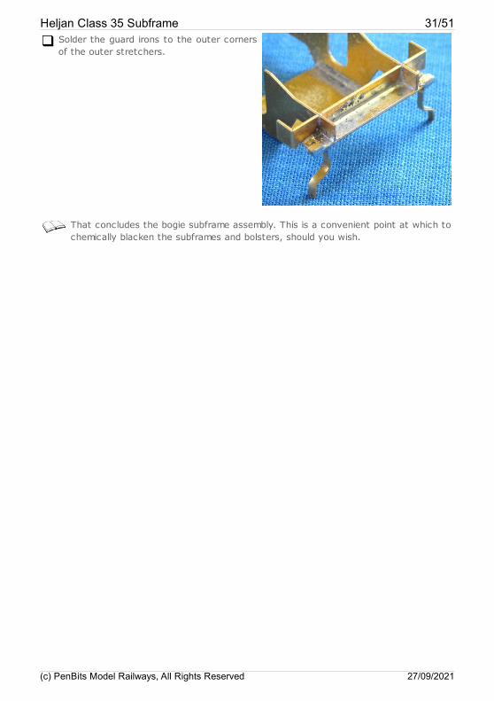
Solder the guard irons to the outer cornersof the outer stretchers.
That concludes the bogie subframe assembly. This is a convenient point at which tochemically blacken the subframes and bolsters, should you wish.
Heljan Class 35 Subframe 31/51
(c) PenBits Model Railways, All Rights Reserved 27/09/2021
Heljan Hymek: Preparing theLocomotive
In this section, we dismantle the loco to remove the bogies and fit the etched PivotFrames into the chassis block.
Following the manufacturers' recommendations for running-in, ensure that thelocomotive is performing smoothly and to your satisfaction generally. Deal with any
issues now, especially those covered by warranty or your basic statutory rights ascustomer, before making any modifications.
Separate the body moulding from thechassis block of the locomotive according
to the manufacturer's instructions.
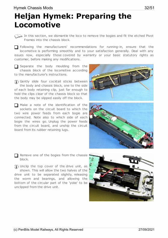
Gently slide four cocktail sticks betweenthe body and chassis block, one to the side
of each body retaining clip, just far enough tohold the clips clear of the chassis block so thatthe body may be slipped easily off the block.
Make a note of the identification of thesockets on the circuit board to which the
two wire power feeds from each bogie areconnected. Note also to which side of eachbogie the wires go. Unplug the power feedsfrom the circuit board, and unship the circuitboard from its rubber retaining lugs.
Remove one of the bogies from the chassisblock.
Unclip the top cover of the drive unit, asshown. This will allow the two halves of the
drive unit to be separated slightly, releasingthe worm and bearings, and allowing thebottom of the circular part of the 'yoke' to beunclipped from the drive unit.
Hymek Chassis Mods 32/51
(c) PenBits Model Railways, All Rights Reserved 27/09/2021
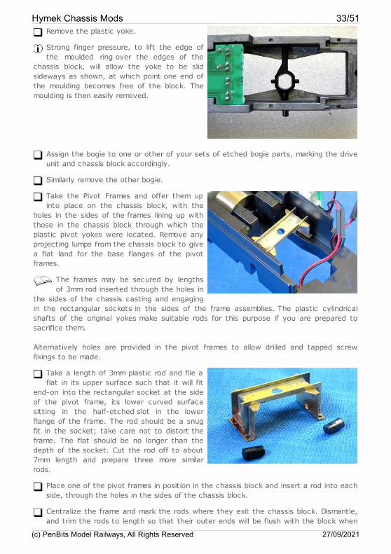
Remove the plastic yoke.
Strong finger pressure, to lift the edge ofthe moulded ring over the edges of the
chassis block, will allow the yoke to be slidsideways as shown, at which point one end ofthe moulding becomes free of the block. Themoulding is then easily removed.
Assign the bogie to one or other of your sets of etched bogie parts, marking the driveunit and chassis block accordingly.
Similarly remove the other bogie.
Take the Pivot Frames and offer them upinto place on the chassis block, with the
holes in the sides of the frames lining up withthose in the chassis block through which theplastic pivot yokes were located. Remove anyprojecting lumps from the chassis block to givea flat land for the base flanges of the pivotframes.
The frames may be secured by lengthsof 3mm rod inserted through the holes in
the sides of the chassis casting and engagingin the rectangular sockets in the sides of the frame assemblies. The plastic cylindricalshafts of the original yokes make suitable rods for this purpose if you are prepared tosacrifice them.
Alternatively holes are provided in the pivot frames to allow drilled and tapped screwfixings to be made.
Take a length of 3mm plastic rod and file aflat in its upper surface such that it will fit
end-on into the rectangular socket at the sideof the pivot frame, its lower curved surfacesitting in the half-etched slot in the lowerflange of the frame. The rod should be a snugfit in the socket; take care not to distort theframe. The flat should be no longer than thedepth of the socket. Cut the rod off to about7mm length and prepare three more similarrods.
Place one of the pivot frames in position in the chassis block and insert a rod into eachside, through the holes in the sides of the chassis block.
Centralize the frame and mark the rods where they exit the chassis block. Dismantle,and trim the rods to length so that their outer ends will be flush with the block when
Hymek Chassis Mods 33/51
(c) PenBits Model Railways, All Rights Reserved 27/09/2021

the frame is centrally positioned.
Repeat for the other pivot frame.
Hymek Chassis Mods 34/51
(c) PenBits Model Railways, All Rights Reserved 27/09/2021
Heljan 4-wheel bogies: FittingWheelsets
Four 2mm diameter plain-ended axles are required. Pin-pointed ends should beremoved. If you are using ready-assembled wheelsets it will be necessary to remove
at least one of the wheels from the axle.
For discussion on the possible choices of wheels, see the Wheels and Axles section of theTechnical Description page on the website.
Clip the top covers on to the drive units. This will prevent the units from falling apartwhile you then spring off the bottom covers to access the wheelsets.
Remove the four OO wheelsets from the drive units, dismantle them and recover thefour final drive gears.
We use one of the axles to check for lateral play. It is important that there issufficient play, for the subsequent free-running of the loco: a little loose is better
than a little tight.
Take one of the axles, slide on its bearing carriers and fit its wheels to the correctback-to-back measurement.
Test fit the axle in the bogie subframe to determine the amount of lateral play. Thereshould be just a little; enough to allow the wheelset to tilt such that the wheel on one
side is raised about 1mm with respect to that on the other, and to allow the wheels tospin freely.
If there is too much play, strip down the wheelset and insert 2mm washers (half- and full-thickness washers are provided on the main fret), between the axle bearings and thewheels, as required.
If there is insufficient lateral play, even with no washers fitted, then strip down thewheelset and reduce the inner width of the wheel bosses accordingly.
Record the washer configuration you arrived at and dismantle the wheelset. If you hadto reduce the inner wheel bosses, repeat the operation on the remaining wheels.
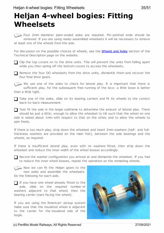
Now we can fit the Heljan gears to thenew axles and assemble the wheelsets.
Do the following for each axle.
If you have one wheel already fitted to theaxle, slide on the required number of
washers adjacent to that wheel, then thebearing carrier (ears facing the wheel).
If you are using the 'American' pickup systemmake sure that the insulated wheel is adjacentto the carrier for the insulated side of thebogie.
Heljan 4-wheel bogies: Fitting Wheelsets 35/51
(c) PenBits Model Railways, All Rights Reserved 27/09/2021

Slide one of the Heljan final drive gears into position centrally on the axle. The gearshould be a tight fit on to the axle, sufficient to transmit drive forces without slipping.
Take care to ensure that the gear is centrally located on the axle.
Slide the bearing carriers, then any washers required, on to the axle.
Fit the wheels to the axle to the correct back-to-back measurement.
Test fit the axle in its slot to confirm that there is sufficient lateral play.
Lubricate the bearings with a light machine oil and ensure that the oil is taken in to allthe axle-bearing interfaces.
That completes the assembly of the wheelsets.
Heljan 4-wheel bogies: Fitting Wheelsets 36/51
(c) PenBits Model Railways, All Rights Reserved 27/09/2021
Heljan Class 35: Springs, BogieAssembly and Rolling Test
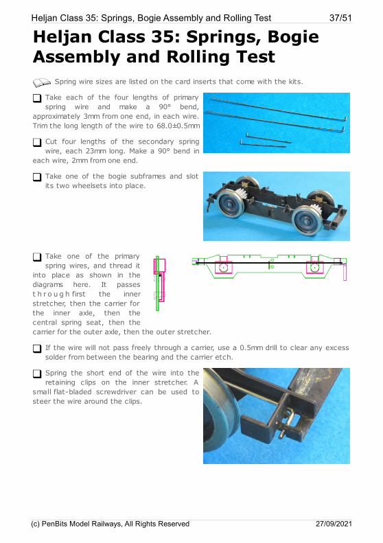
Spring wire sizes are listed on the card inserts that come with the kits.
Take each of the four lengths of primaryspring wire and make a 90° bend,
approximately 3mm from one end, in each wire.Trim the long length of the wire to 68.0±0.5mm
Cut four lengths of the secondary springwire, each 23mm long. Make a 90° bend in
each wire, 2mm from one end.
Take one of the bogie subframes and slotits two wheelsets into place.
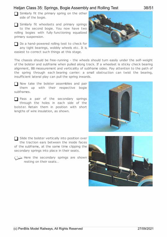
Take one of the primaryspring wires, and thread it
into place as shown in thediagrams here. It passest h r o u g h first the innerstretcher, then the carrier forthe inner axle, then thecentral spring seat, then thecarrier for the outer axle, then the outer stretcher.
If the wire will not pass freely through a carrier, use a 0.5mm drill to clear any excesssolder from between the bearing and the carrier etch.
Spring the short end of the wire into theretaining clips on the inner stretcher. A
small flat-bladed screwdriver can be used tosteer the wire around the clips.
Heljan Class 35: Springs, Bogie Assembly and Rolling Test 37/51
(c) PenBits Model Railways, All Rights Reserved 27/09/2021
Similarly fit the primary spring on the otherside of the bogie.
Similarly fit wheelsets and primary springsto the second bogie. You now have two
rolling bogies with fully functioning equalizedprimary suspension.
Do a hand-powered rolling test to check forany tight bearings, wobbly wheels etc. It is
easiest to correct such things at this stage.
The chassis should be free-running - the wheels should turn easily under the self-weightof the bolster and subframe when pulled along track. If a wheelset is sticky check bearingalignment, BB measurement and verticality of subframe sides. Pay attention to the path ofthe spring through each bearing carrier: a small obstruction can twist the bearing,insufficient lateral play can pull the spring inwards.
Now take the bolster assemblies and pairthem up with their respective bogie
subframes.
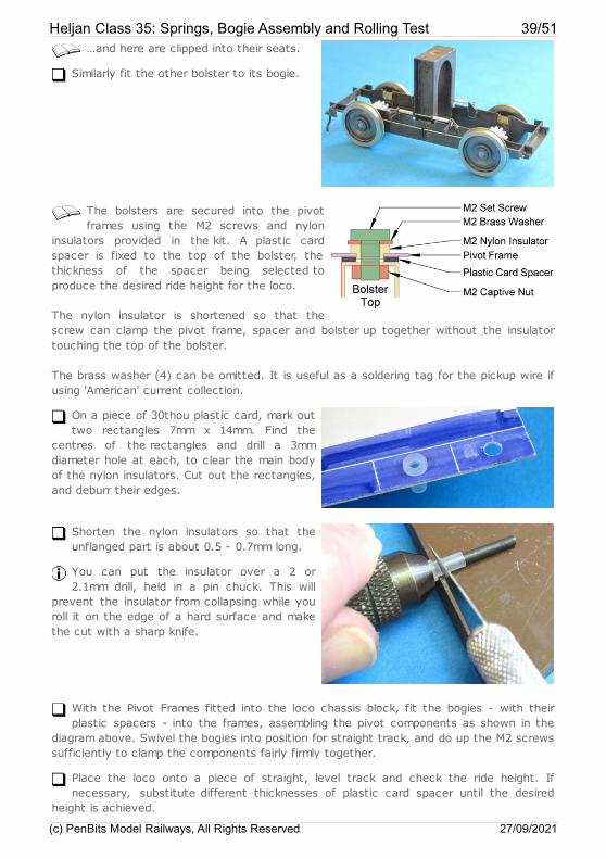
Pass a pair of the secondary springsthrough the holes in each side of the
bolster. Retain them in position with shortlengths of wire insulation, as shown.
Slide the bolster vertically into position overthe traction ears between the inside faces
of the subframe, at the same time clipping thesecondary springs into place in their seats.
Here the secondary springs are shownresting on their seats…
Heljan Class 35: Springs, Bogie Assembly and Rolling Test 38/51
(c) PenBits Model Railways, All Rights Reserved 27/09/2021
…and here are clipped into their seats.
Similarly fit the other bolster to its bogie.
The bolsters are secured into the pivotframes using the M2 screws and nylon
insulators provided in the kit. A plastic cardspacer is fixed to the top of the bolster, thethickness of the spacer being selected toproduce the desired ride height for the loco.
The nylon insulator is shortened so that thescrew can clamp the pivot frame, spacer and bolster up together without the insulatortouching the top of the bolster.
The brass washer (4) can be omitted. It is useful as a soldering tag for the pickup wire ifusing 'American' current collection.
On a piece of 30thou plastic card, mark outtwo rectangles 7mm x 14mm. Find the
centres of the rectangles and drill a 3mmdiameter hole at each, to clear the main bodyof the nylon insulators. Cut out the rectangles,and deburr their edges.
Shorten the nylon insulators so that theunflanged part is about 0.5 - 0.7mm long.
You can put the insulator over a 2 or2.1mm drill, held in a pin chuck. This will
prevent the insulator from collapsing while youroll it on the edge of a hard surface and makethe cut with a sharp knife.
With the Pivot Frames fitted into the loco chassis block, fit the bogies - with theirplastic spacers - into the frames, assembling the pivot components as shown in the
diagram above. Swivel the bogies into position for straight track, and do up the M2 screwssufficiently to clamp the components fairly firmly together.
Place the loco onto a piece of straight, level track and check the ride height. Ifnecessary, substitute different thicknesses of plastic card spacer until the desired
height is achieved.
Heljan Class 35: Springs, Bogie Assembly and Rolling Test 39/51
(c) PenBits Model Railways, All Rights Reserved 27/09/2021
Ride height is normally set to give a nominal buffer height of around 13.8mm aboverail level. You may well find that there is a variation in the order of 0.5mm over the
four buffers, just in the way that they've been fitted to the loco. You might also wish toput the body back on to the loco and check for maximum height overall, and then reflecton whether the manufacturer has got the buffers in the right place. Ultimately, working totenths of millimetres, it will be a judgement call as to exactly where the correct rideheight lies.
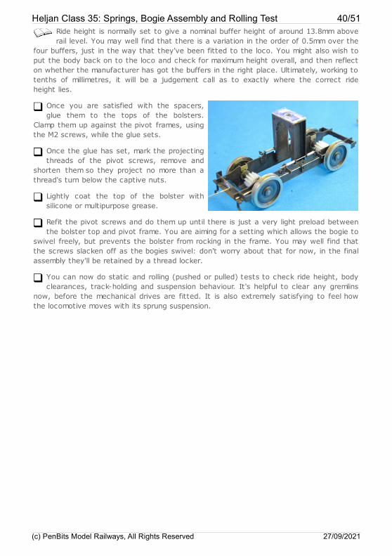
Once you are satisfied with the spacers,glue them to the tops of the bolsters.
Clamp them up against the pivot frames, usingthe M2 screws, while the glue sets.
Once the glue has set, mark the projectingthreads of the pivot screws, remove and
shorten them so they project no more than athread's turn below the captive nuts.
Lightly coat the top of the bolster withsilicone or multipurpose grease.
Refit the pivot screws and do them up until there is just a very light preload betweenthe bolster top and pivot frame. You are aiming for a setting which allows the bogie to
swivel freely, but prevents the bolster from rocking in the frame. You may well find thatthe screws slacken off as the bogies swivel: don't worry about that for now, in the finalassembly they'll be retained by a thread locker.
You can now do static and rolling (pushed or pulled) tests to check ride height, bodyclearances, track-holding and suspension behaviour. It's helpful to clear any gremlins
now, before the mechanical drives are fitted. It is also extremely satisfying to feel howthe locomotive moves with its sprung suspension.
Heljan Class 35: Springs, Bogie Assembly and Rolling Test 40/51
(c) PenBits Model Railways, All Rights Reserved 27/09/2021

Heljan Class 35: Cosmetic BogieDetail
This section deals with fitting the side frames to the etched bogie subframe, addingthe etched representations of brake gear if desired. You will possibly be keen to get
the loco running, so the final fit of the sideframes and of the brake gear can be postponedto the very end of the build, if you wish. However, it is probably as well to do the first fitof the sideframes and alignment of the outriggers as part of the unpowered testing.
Unplug the four sideframe mouldings from the drive units. Mark the rear faces of thetwo from the bogie having the triangular symbol, so that their locations on the loco
are uniquely identified.
Shorten the two mounting turrets on eachsideframe to 3.5mm.
File away the thickened pull rods at theends of each sideframe moulding until they
have virtually no thickness.
Mount the sideframes on the bogies, engaging their turrets on to the etchedoutriggers. Make final adjustments to the length of the turrets so that the inside faces
of the sideframes sit flush against the faces of the bogie stretcher ends when the turretsare pushed fully home on the outriggers (taking the opportunity to correct any bowing ofthe mouldings).
Check the alignment of the top edges of the sideframes with the base of the chassisblock. This can be adjusted by firmly, but carefully, twisting the outriggers up or
down, with small pliers.
File a small chamfer on the top inside edge of each turret, to allow the secondarysprings to be inserted or removed once the sideframe has been glued in place.
It is at this point that you may wish to postpone the following operations to theend of the build, after you have the loco running.
Heljan have provided no brake shoes or hangers on the sideframe mouldings. Evenwhen looking at the real locos, they are virtually invisible from most viewpoints.
However, when we prepared our test build, there seemed to be something missing and sowe have included representations of the brake gear on the production etch. On fitting,given that we have had to allow extra clearances between shoe and tread for the model,they have indeed proved still to be virtually invisible. We suggest that they are, at thevery least, optional. You can leave them until the very end of your build, and make up
Heljan Class 35: Cosmetic Bogie Detail 41/51
(c) PenBits Model Railways, All Rights Reserved 27/09/2021
your own mind: assembly instructions follow here.
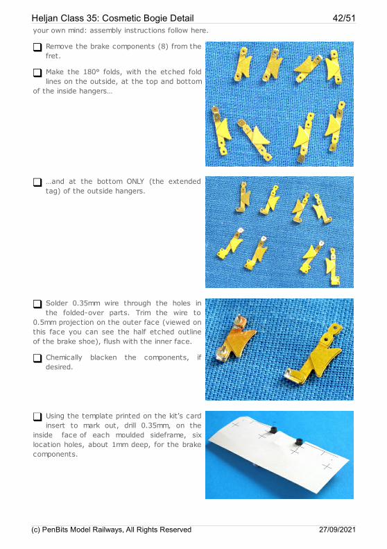
Remove the brake components (8) from thefret.
Make the 180° folds, with the etched foldlines on the outside, at the top and bottom
of the inside hangers…
…and at the bottom ONLY (the extendedtag) of the outside hangers.
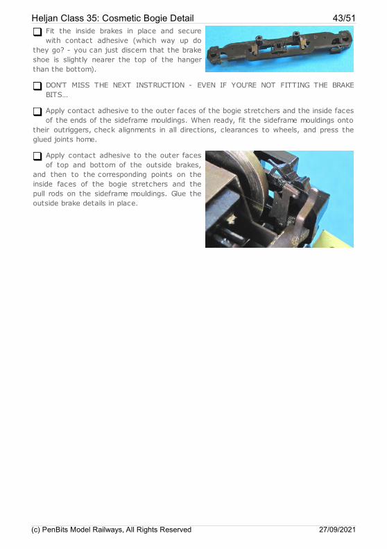
Solder 0.35mm wire through the holes inthe folded-over parts. Trim the wire to
0.5mm projection on the outer face (viewed onthis face you can see the half etched outlineof the brake shoe), flush with the inner face.
Chemically blacken the components, ifdesired.
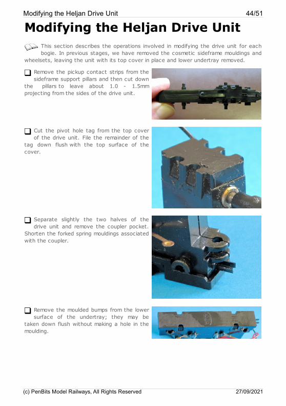
Using the template printed on the kit's cardinsert to mark out, drill 0.35mm, on the
inside face of each moulded sideframe, sixlocation holes, about 1mm deep, for the brakecomponents.
Heljan Class 35: Cosmetic Bogie Detail 42/51
(c) PenBits Model Railways, All Rights Reserved 27/09/2021
Fit the inside brakes in place and securewith contact adhesive (which way up do
they go? - you can just discern that the brakeshoe is slightly nearer the top of the hangerthan the bottom).
DON'T MISS THE NEXT INSTRUCTION - EVEN IF YOU'RE NOT FITTING THE BRAKEBITS…
Apply contact adhesive to the outer faces of the bogie stretchers and the inside facesof the ends of the sideframe mouldings. When ready, fit the sideframe mouldings onto
their outriggers, check alignments in all directions, clearances to wheels, and press theglued joints home.
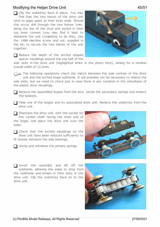
Apply contact adhesive to the outer facesof top and bottom of the outside brakes,
and then to the corresponding points on theinside faces of the bogie stretchers and thepull rods on the sideframe mouldings. Glue theoutside brake details in place.
Heljan Class 35: Cosmetic Bogie Detail 43/51
(c) PenBits Model Railways, All Rights Reserved 27/09/2021
Modifying the Heljan Drive UnitThis section describes the operations involved in modifying the drive unit for eachbogie. In previous stages, we have removed the cosmetic sideframe mouldings and
wheelsets, leaving the unit with its top cover in place and lower undertray removed.
Remove the pickup contact strips from thesideframe support pillars and then cut down
the pillars to leave about 1.0 - 1.5mmprojecting from the sides of the drive unit.
Cut the pivot hole tag from the top coverof the drive unit. File the remainder of the
tag down flush with the top surface of thecover.
Separate slightly the two halves of thedrive unit and remove the coupler pocket.
Shorten the forked spring mouldings associatedwith the coupler.
Remove the moulded bumps from the lowersurface of the undertray; they may be
taken down flush without making a hole in themoulding.
Modifying the Heljan Drive Unit 44/51
(c) PenBits Model Railways, All Rights Reserved 27/09/2021
Clip the undertray back in place. You mayfind that the two halves of the drive unit
tend to gape apart at their inner ends. Shouldthis occur, drill through the two halves 1mm,along the line of the stud and socket in theirtop inner corners (you may find it best todismantle the unit completely to do this). Usethe 14BA machine screw and nut, supplied inthe kit, to secure the two halves of the unittogether.
Reduce the depth of the arched shapedspacer mouldings around the top half of the
axle slots in the drive unit (highlighted white in the photo here), aiming for a nominaloverall width of 12.2mm.
The following operations check the match between the axle centres of the driveunit and the etched bogie subframe. It will probably not be necessary to relieve the
axle slots, but we need to check just in case there is any variation in the wheelbase ofthe plastic drive mouldings.
Remove the assembled bogies from the loco. Unclip the secondary springs and removethe bolsters.
Take one of the bogies and its associated drive unit. Remove the undertray from thedrive unit.
Orientate the drive unit, with the socket forthe cardan shaft facing the inner end of
the bogie, and place the drive unit over theaxles.
Check that the arched mouldings on thedrive unit have been reduced sufficiently to
fit loosely between the axle bearings.
Unclip and withdraw the primary springs.
Invert the assembly and lift off thesubframe, allowing the axles to drop from
the subframe and remain in their slots in thedrive unit. Clip the undertray back on to thedrive unit.
Modifying the Heljan Drive Unit 45/51
(c) PenBits Model Railways, All Rights Reserved 27/09/2021
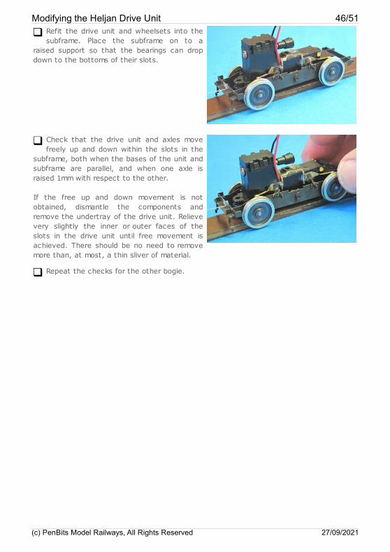
Refit the drive unit and wheelsets into thesubframe. Place the subframe on to a
raised support so that the bearings can dropdown to the bottoms of their slots.
Check that the drive unit and axles movefreely up and down within the slots in the
subframe, both when the bases of the unit andsubframe are parallel, and when one axle israised 1mm with respect to the other.
If the free up and down movement is notobtained, dismantle the components andremove the undertray of the drive unit. Relievevery slightly the inner or outer faces of theslots in the drive unit until free movement isachieved. There should be no need to removemore than, at most, a thin sliver of material.
Repeat the checks for the other bogie.
Modifying the Heljan Drive Unit 46/51
(c) PenBits Model Railways, All Rights Reserved 27/09/2021
Heljan Class 35: Pickups andPower
There are several options for arranging power pickups and you may have your ownpreference. However, as space is rather constrained in this bogie design, we
describe here the method that we came up with and applied successfully.
Remove the undertrays and wheelsets from the drive unit.
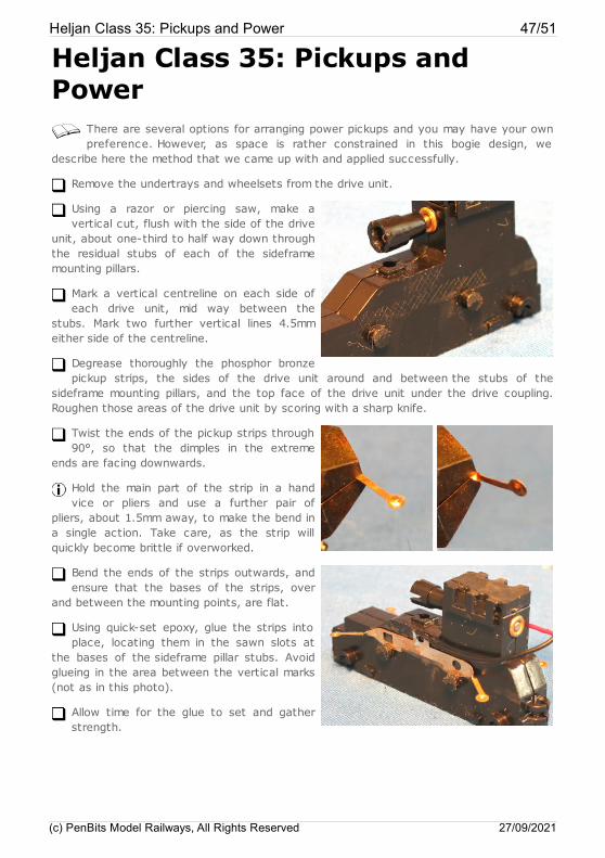
Using a razor or piercing saw, make avertical cut, flush with the side of the drive
unit, about one-third to half way down throughthe residual stubs of each of the sideframemounting pillars.
Mark a vertical centreline on each side ofeach drive unit, mid way between the
stubs. Mark two further vertical lines 4.5mmeither side of the centreline.
Degrease thoroughly the phosphor bronzepickup strips, the sides of the drive unit around and between the stubs of the
sideframe mounting pillars, and the top face of the drive unit under the drive coupling.Roughen those areas of the drive unit by scoring with a sharp knife.
Twist the ends of the pickup strips through90°, so that the dimples in the extreme
ends are facing downwards.
Hold the main part of the strip in a handvice or pliers and use a further pair of
pliers, about 1.5mm away, to make the bend ina single action. Take care, as the strip willquickly become brittle if overworked.
Bend the ends of the strips outwards, andensure that the bases of the strips, over
and between the mounting points, are flat.
Using quick-set epoxy, glue the strips intoplace, locating them in the sawn slots at
the bases of the sideframe pillar stubs. Avoidglueing in the area between the vertical marks(not as in this photo).
Allow time for the glue to set and gatherstrength.
Heljan Class 35: Pickups and Power 47/51
(c) PenBits Model Railways, All Rights Reserved 27/09/2021
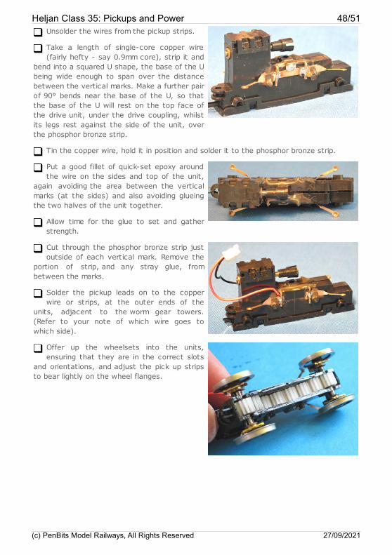
Unsolder the wires from the pickup strips.
Take a length of single-core copper wire(fairly hefty - say 0.9mm core), strip it and
bend into a squared U shape, the base of the Ubeing wide enough to span over the distancebetween the vertical marks. Make a further pairof 90° bends near the base of the U, so thatthe base of the U will rest on the top face ofthe drive unit, under the drive coupling, whilstits legs rest against the side of the unit, overthe phosphor bronze strip.
Tin the copper wire, hold it in position and solder it to the phosphor bronze strip.
Put a good fillet of quick-set epoxy aroundthe wire on the sides and top of the unit,
again avoiding the area between the verticalmarks (at the sides) and also avoiding glueingthe two halves of the unit together.
Allow time for the glue to set and gatherstrength.
Cut through the phosphor bronze strip justoutside of each vertical mark. Remove the
portion of strip, and any stray glue, frombetween the marks.
Solder the pickup leads on to the copperwire or strips, at the outer ends of the
units, adjacent to the worm gear towers.(Refer to your note of which wire goes towhich side).
Offer up the wheelsets into the units,ensuring that they are in the correct slots
and orientations, and adjust the pick up stripsto bear lightly on the wheel flanges.
Heljan Class 35: Pickups and Power 48/51
(c) PenBits Model Railways, All Rights Reserved 27/09/2021

Re-fit the undertrays to the drive units,securing the wheelsets in place.
Heljan Class 35: Pickups and Power 49/51
(c) PenBits Model Railways, All Rights Reserved 27/09/2021
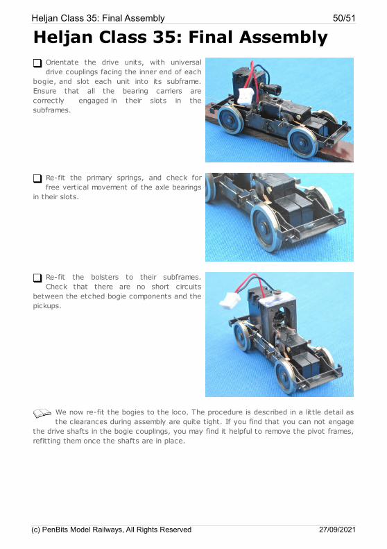
Heljan Class 35: Final AssemblyOrientate the drive units, with universaldrive couplings facing the inner end of each
bogie, and slot each unit into its subframe.Ensure that all the bearing carriers arecorrectly engaged in their slots in thesubframes.
Re-fit the primary springs, and check forfree vertical movement of the axle bearings
in their slots.
Re-fit the bolsters to their subframes.Check that there are no short circuits
between the etched bogie components and thepickups.
We now re-fit the bogies to the loco. The procedure is described in a little detail asthe clearances during assembly are quite tight. If you find that you can not engage
the drive shafts in the bogie couplings, you may find it helpful to remove the pivot frames,refitting them once the shafts are in place.
Heljan Class 35: Final Assembly 50/51
(c) PenBits Model Railways, All Rights Reserved 27/09/2021
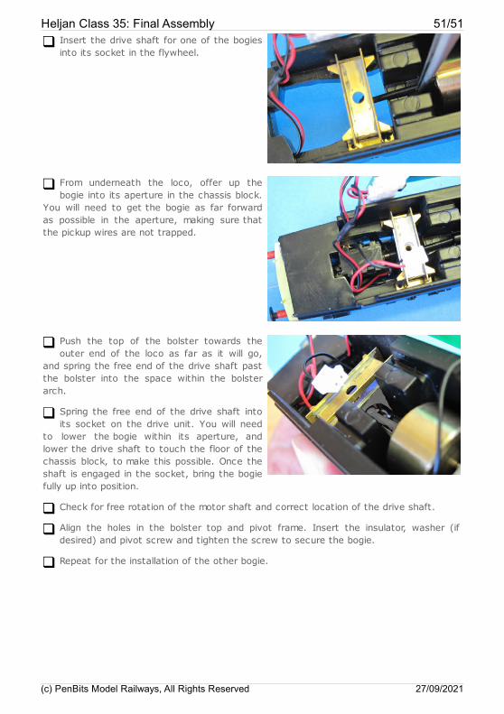
Insert the drive shaft for one of the bogiesinto its socket in the flywheel.
From underneath the loco, offer up thebogie into its aperture in the chassis block.
You will need to get the bogie as far forwardas possible in the aperture, making sure thatthe pickup wires are not trapped.
Push the top of the bolster towards theouter end of the loco as far as it will go,
and spring the free end of the drive shaft pastthe bolster into the space within the bolsterarch.
Spring the free end of the drive shaft intoits socket on the drive unit. You will need
to lower the bogie within its aperture, andlower the drive shaft to touch the floor of thechassis block, to make this possible. Once theshaft is engaged in the socket, bring the bogiefully up into position.
Check for free rotation of the motor shaft and correct location of the drive shaft.
Align the holes in the bolster top and pivot frame. Insert the insulator, washer (ifdesired) and pivot screw and tighten the screw to secure the bogie.
Repeat for the installation of the other bogie.
Heljan Class 35: Final Assembly 51/51
(c) PenBits Model Railways, All Rights Reserved 27/09/2021
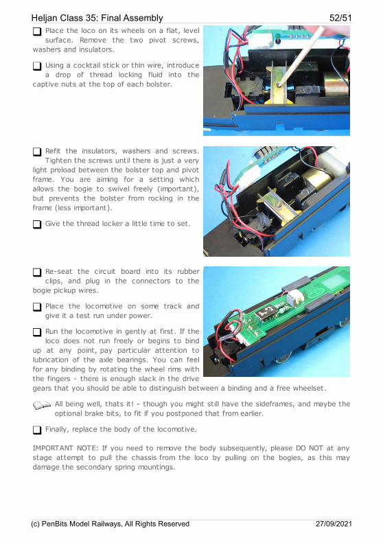
Place the loco on its wheels on a flat, levelsurface. Remove the two pivot screws,
washers and insulators.
Using a cocktail stick or thin wire, introducea drop of thread locking fluid into the
captive nuts at the top of each bolster.
Refit the insulators, washers and screws.Tighten the screws until there is just a very
light preload between the bolster top and pivotframe. You are aiming for a setting whichallows the bogie to swivel freely (important),but prevents the bolster from rocking in theframe (less important).
Give the thread locker a little time to set.
Re-seat the circuit board into its rubberclips, and plug in the connectors to the
bogie pickup wires.
Place the locomotive on some track andgive it a test run under power.
Run the locomotive in gently at first. If theloco does not run freely or begins to bind
up at any point, pay particular attention tolubrication of the axle bearings. You can feelfor any binding by rotating the wheel rims withthe fingers - there is enough slack in the drivegears that you should be able to distinguish between a binding and a free wheelset.
All being well, thats it! - though you might still have the sideframes, and maybe theoptional brake bits, to fit if you postponed that from earlier.
Finally, replace the body of the locomotive.
IMPORTANT NOTE: If you need to remove the body subsequently, please DO NOT at anystage attempt to pull the chassis from the loco by pulling on the bogies, as this maydamage the secondary spring mountings.
Heljan Class 35: Final Assembly 52/51
(c) PenBits Model Railways, All Rights Reserved 27/09/2021