Embed Size (px)
Citation preview
CHAPTER 2
GENERAL MAINTENANCE EQUIPMENT
As an ABF, you are routinely assigned tasksrequiring the use of hand or power tools. It is to youradvantage to become familiar with the tools you willuse to accomplish these tasks. The right tool for theright job is an old, but time proven, proverb.
SAFETY is paramount when you are usingtools— power or hand operated. Special care shouldbe used with all wood or metal cutting tools. Eyegoggles must be in place before cutting tools are used.
Power tools are more dangerous thannonpowered tools. Use power tools only if you arefamiliar with them and have been checked out ontheir use and proper operation by a competentauthority.
Tools and Their Uses, NAVEDTRA 10085-B2,contains more detailed information on the varioustools the ABF will use.
COMMON HAND TOOLS
LEARNING OBJECTIVES: Identify thecommon hand tools used by the ABF. Explainthe use and care of hand tools.
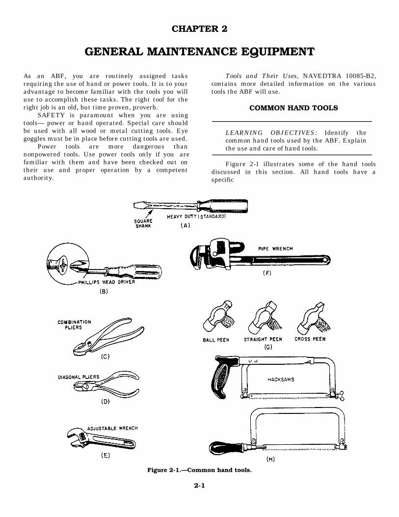
Figure 2-1 illustrates some of the hand toolsdiscussed in this section. All hand tools have aspecific
Figure 2-1.—Common hand tools.
2-1
purpose and should be used only on the objects theyare designed for. When you use a hand tool for otherpurposes, you usually damage both the tool and theobject it is used on. Use screwdrivers to drive andremove screws. Do not use them to scrape paint, as apry bar or chisel, and certainly never use them to testan electrical circuit.
STANDARD SCREWDRIVER
Three main parts make up the construction of thestandard screwdriver (fig. 2-1, view A), the handle,the shank, and the end. The end (called the blade) fitsinto the screw slot. When using a screwdriver, selectthe proper size blade for the job intended. A blade toolarge or too small causes the screwdriver blade andthe screwhead to become damaged. At least 75 per-cent of the screw slot should be filled by the blade forproper fit.
PHILLIPS HEADSCREWDRIVER
A Phillips head screwdriver (fig. 2-1, view B)differs in construction from a standard screwdriveronly in that the tip is shaped to fit the special cavity inthe Phillips screwhead. A standard screwdriver mustnever be used in a Phillips screwhead as damage willoccur to it. The Phillips cavity should be filled com-pletely by the selected driver for proper fit.
HAMMER
The hammer (fig. 2-1. view G) most used by theABF is the ball peen. The ball peen hammer is usedfor working metals, such as chiseling rivets and shear-ing metal.
COMBINATION PLIERS
Combination pliers (fig. 2-1, view C) are manu-factured with straight serrated jaws for gripping ob-jects. The pivots, with which the jaws are attached, areadjustable to fit different size objects. Pliers shouldnot be used to grasp the shanks of screwdrivers to gaingreater twisting force.
DIAGONAL PLIERS
Diagonal pliers (fig. 2-1, view D) are used onlyfor cutting small material such as wire or cotter pins.They are designed specifically for cutting. They
should NOT be used for grasping objects such as nutsand bolts.
ADJUSTABLE WRENCHES
An adjustable wrench (fig. 2-1, view E) is notintended to replace an open-end wrench, but it isuseful in working in restricted areas. In addition, itcan be adjusted to fit odd-sized nuts or bolts. Thiswrench is often called a knuckle buster because me-chanics frequently suffer the consequences of using itimproperly.
PIPE WRENCHES
A pipe wrench (fig. 2-1, view F) is primarily usedfor rotating round stock and/or various pipes and pip-ing. The most common pipe wrench is the Stillson. Ithas two jaws that have serrated teeth to provide agripping ability. The larger jaw is a fixed jaw. Thesmaller jaw is adjustable and the weaker of the twojaws. Whenever a Stillson wrench is used, it should beapplied in such a manner that the fixed jaw providesthe twisting force. These wrenches also come in vary-ing lengths, which makes the jaw sizes vary. A Still-son wrench should never be used on machinedsurfaces, as the teeth tend to mar or otherwise ruin themetal.
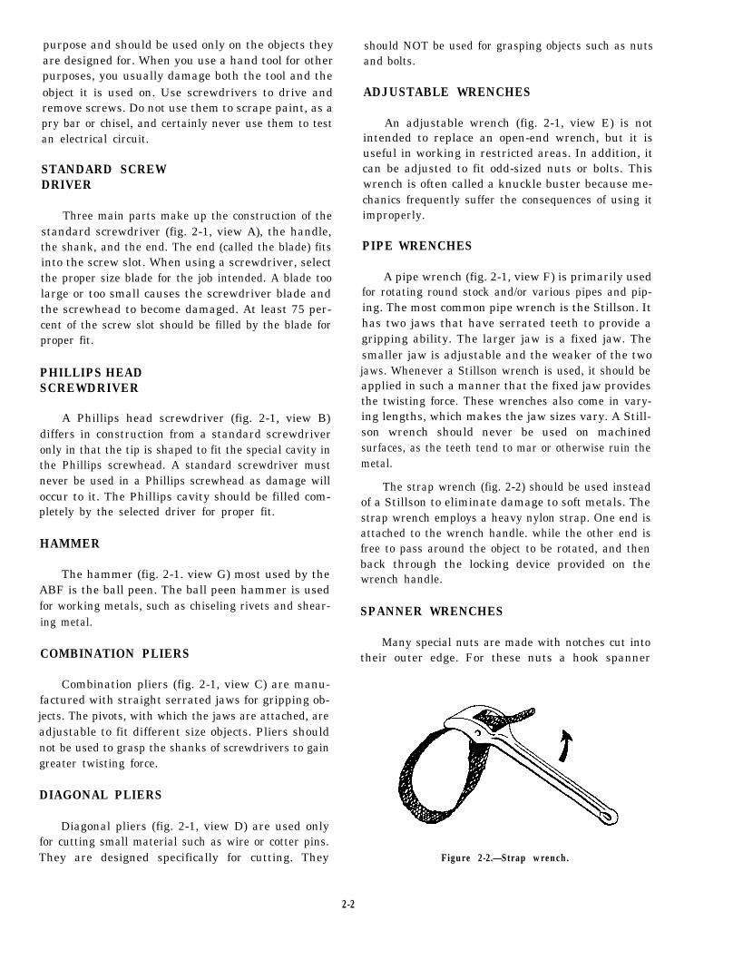
The strap wrench (fig. 2-2) should be used insteadof a Stillson to eliminate damage to soft metals. Thestrap wrench employs a heavy nylon strap. One end isattached to the wrench handle. while the other end isfree to pass around the object to be rotated, and thenback through the locking device provided on thewrench handle.
SPANNER WRENCHES
Many special nuts are made with notches cut intotheir outer edge. For these nuts a hook spanner
Figure 2-2.—Strap wrench.
2-2
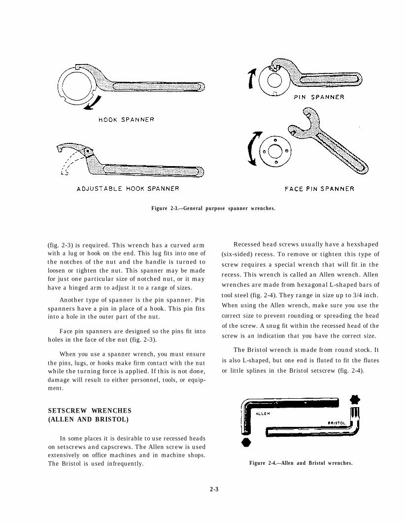
(fig. 2-3) is required. This wrench has a curved armwith a lug or hook on the end. This lug fits into one ofthe notches of the nut and the handle is turned toloosen or tighten the nut. This spanner may be madefor just one particular size of notched nut, or it mayhave a hinged arm to adjust it to a range of sizes.
Another type of spanner is the pin spanner. Pinspanners have a pin in place of a hook. This pin fitsinto a hole in the outer part of the nut.
Face pin spanners are designed so the pins fit intoholes in the face of the nut (fig. 2-3).
When you use a spanner wrench, you must ensurethe pins, lugs, or hooks make firm contact with the nutwhile the turning force is applied. If this is not done,damage will result to either personnel, tools, or equip-ment.
SETSCREW WRENCHES(ALLEN AND BRISTOL)
In some places it is desirable to use recessed headson setscrews and capscrews. The Allen screw is usedextensively on office machines and in machine shops.The Bristol is used infrequently.
Figure 2-3.—General purpose spanner wrenches.
Recessed head screws usually have a hexshaped
(six-sided) recess. To remove or tighten this type of
screw requires a special wrench that will fit in the
recess. This wrench is called an Allen wrench. Allen
wrenches are made from hexagonal L-shaped bars of
tool steel (fig. 2-4). They range in size up to 3/4 inch.
When using the Allen wrench, make sure you use the
correct size to prevent rounding or spreading the head
of the screw. A snug fit within the recessed head of the
screw is an indication that you have the correct size.
The Bristol wrench is made from round stock. It
is also L-shaped, but one end is fluted to fit the flutes
or little splines in the Bristol setscrew (fig. 2-4).
Figure 2-4.—Allen and Bristol wrenches.
2-3
SOCKET WRENCH
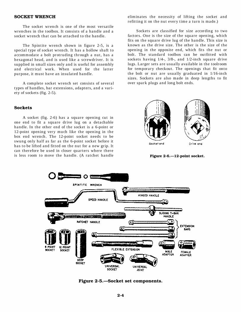
The socket wrench is one of the most versatilewrenches in the toolbox. It consists of a handle and asocket wrench that can be attached to the handle.
The Spintite wrench shown in figure 2-5, is aspecial type of socket wrench. It has a hollow shaft toaccommodate a bolt protruding through a nut, has ahexagonal head, and is used like a screwdriver. It issupplied in small sizes only and is useful for assemblyand electrical work. When used for the latterpurpose, it must have an insulated handle.
A complete socket wrench set consists of severaltypes of handles, bar extensions, adapters, and a vari-ety of sockets (fig. 2-5).
Sockets
A socket (fig. 2-6) has a square opening cut inone end to fit a square drive lug on a detachablehandle. In the other end of the socket is a 6-point or12-point opening very much like the opening in thebox end wrench. The 12-point socket needs to beswung only half as far as the 6-point socket before ithas to be lifted and fitted on the nut for a new grip. Itcan therefore be used in closer quarters where thereis less room to move the handle. (A ratchet handle
eliminates the necessity of lifting the socket andrefitting it on the nut every time a turn is made.)
Sockets are classified for size according to twofactors. One is the size of the square opening, whichfits on the square drive lug of the handle. This size isknown as the drive size. The other is the size of theopening in the opposite end, which fits the nut orbolt. The standard toolbox can be outfitted withsockets having 1/4-, 3/8-, and 1/2-inch square drivelugs. Larger sets are usually available in the toolroomfor temporary checkout. The openings that fit ontothe bolt or nut are usually graduated in 1/16-inchsizes. Sockets are also made in deep lengths to fitover spark plugs and long bolt ends.
Figure 2-6.—12-point socket.
Figure 2-5.—Socket set components.
2-4
Socket Handles
There are four types of handles used with thesesockets. (See fig. 2-5) Each type has special advan-tages, and the experienced worker chooses the onesuited for the job at hand. The square driving lug onthe socket wrench handles has a spring-loaded ballthat fits into a recess in the socket receptacle. Thismated ball-recess feature keeps the socket engagedwith the drive lug during normal usage. A slight pullon the socket, however, disassembles the connection.
RATCHET.— The ratchet handle has a reversinglever that operates a pawl (or dog) inside the head ofthe tool. Pulling the handle in one direction causes thepawl to engage in the ratchet teeth and turn the socket.Moving the handle in the opposite direction causesthe pawl to slide over the teeth, permitting the handleto back up without moving the socket. This allowsrapid turning of the nut or bolt after each partial turnof the handle. With the reversing lever in one position,the handle is used for tightening. In the other position,it is used for loosening.
HINGED HANDLE.— The hinged handle is alsovery convenient. To loosen tight nuts, swing the han-dle at right angles to the socket. This gives the greatestpossible leverage. After loosening the nut to the pointwhere it turns easily, move the handle into the verticalposition, and then turn the handle with the fingers.
SLIDING T-BAR HANDLE.— When using thesliding bar or T-handle, the head can be positionedanywhere along the sliding bar. Select the positionthat is needed for the job at hand.
SPEED HANDLE.— The speed handle isworked like the wood-worker’s brace. After the nutsare first loosened with the sliding bar handle or theratchet handle, the speed handle can be used to re-move the nuts more quickly. In many instances thespeed handle is not strong enough to be used forbreaking loose or tightening the nut. The speed socketwrench should be used carefully to avoid damagingthe nut threads.
Accessories
To complete the socket wrench set, there are sev-eral accessory items. Extension bars of differentlengths are made to extend the distance from thesocket to the handle. A universal joint allows the nutto be turned with the wrench handle at an angle.
Universal sockets are also available. The use of uni-versal joints, bar extensions, and universal sockets incombination with appropriate handles makes it possi-ble to form a variety of tools that will reach otherwiseinaccessible nuts and bolts.
Another accessory item is an adapter that allowsyou to use a handle having one size of drive and asocket having a different size drive. For example, a3/8- by 1/4-inch adapter makes it possible to turn all1/4-inch square drive sockets with any 3/8-inchsquare drive handle.
HACKSAW
The hacksaw is a handy portable metal cuttingtool that can be used for cutting sheet metal, bolts, andpipe. A hacksaw cuts on the push stroke only; theblade should be installed in the frame with the teethfacing away from the handle. Figure 2-1, view H,shows two types of hacksaws with the blade in theproper position.
CHISELS
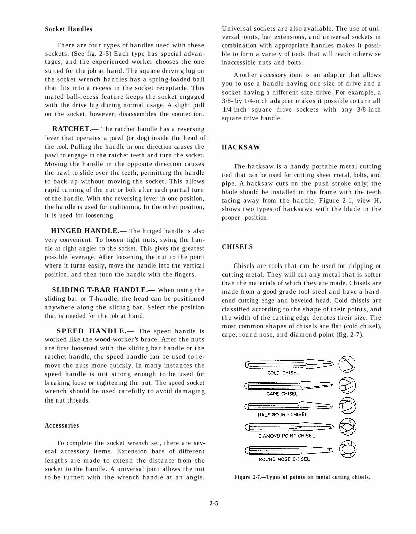
Chisels are tools that can be used for chipping orcutting metal. They will cut any metal that is softerthan the materials of which they are made. Chisels aremade from a good grade tool steel and have a hard-ened cutting edge and beveled head. Cold chisels areclassified according to the shape of their points, andthe width of the cutting edge denotes their size. Themost common shapes of chisels are flat (cold chisel),cape, round nose, and diamond point (fig. 2-7).
Figure 2-7.—Types of points on metal cutting chisels.
2-5
The type of chisel most commonly used is the flatcold chisel, which serves to cut rivets, split nuts, chipcastings, and thin metal sheets. The cape chisel isused for special jobs like cutting keyways, narrowgrooves, and square corners. Round-nose chiselsmake circular grooves and chip inside corners with afillet. Finally, the diamond-point is used for cuttingV-grooves and sharp comers.
As with other tools there is a correct techniquefor using a chisel. Select a chisel that is large enoughfor the job. Be sure to use a hammer that matches thechisel; that is, the larger the chisel, the heavier thehammer. A heavy chisel will absorb the blows of alight hammer and will do virtually no cutting.
As a general rule, hold the chisel in the left handwith the thumb and first finger about 1-inch from thetop. It should be held steadily but not tightly. Thefinger muscles should be relaxed, so if the hammerstrikes the hand it will permit the hand to slide downthe tool and lessen the effect of the blow. Keep theeyes on the cutting edge of the chisel, not on thehead, and swing the hammer in the same plane asthe body of the chisel. If you have a lot of chiseling todo, slide a piece of rubber hose over the chisel. Thiswill lessen the shock to your hand.
When using a chisel for chipping, always weargoggles to protect your eyes. If other personnel areworking close by, ensure they are protected fromflying chips by erecting a screen or shield to containthe chips. Remember that the time to take theseprecautions is before you start the job.
FILES
A toolkit for nearly every rating in the Navy isnot complete unless it contains an assortment of files.There are several different types of files in commonuse, and each type may range in length from 3 to 18inches.
Grades
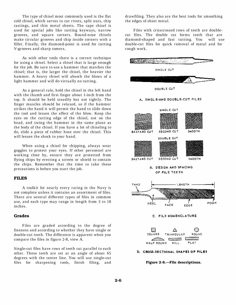
Files are graded according to the degree offineness and according to whether they have single ordouble-cut teeth. The difference is apparent when youcompare the files in figure 2-8, view A.
Single-cut files have rows of teeth cut parallel to eachother. These teeth are set at an angle of about 65degrees with the center line. You will use single-cutfiles for sharpening tools, finish filing, and
drawfiling. They also are the best tools for smoothingthe edges of sheet metal.
Files with crisscrossed rows of teeth are double-cut files. The double cut forms teeth that arediamond-shaped and fast cutting. You will usedouble-cut files for quick removal of metal and forrough work.
Figure 2-8.—File descriptions.
2-6
Files are also graded according to the spacing andsize of their teeth, or their coarseness and fineness.Some of these grades are pictured in figure 2-8, viewB. In addition to the three grades shown, you may usesome DEAD SMOOTH files, which have very fineteeth, and some ROUGH files with very coarse teeth.The fineness or coarseness of file teeth is also influ-enced by the length of the file. The length of a fileis the distance from the tip to the heel, and doesnot include the tang (fig. 2-8, view C). When you havea chance, compare the actual size of the teeth of a6-inch, single-cut smooth file and a 12-inch, single-cutsmooth file. You will notice the 6-inch file has moreteeth per inch than the 12-inch file.
Shapes
Files come in different shapes. Therefore, in se-lecting a file for a job, the shape of the finished workmust be considered. Some of the cross-sectionalshapes are shown in figure 2-8, view D.
TRIANGULAR files are tapered (longitudinally)on all three sides. They are used to file acute internalangles and to clear out square comers. Special trian-gular files are used to file saw teeth.
MILL files are tapered in both width and thick-ness. One edge has no teeth and is known as a SAFEEDGE. Mill files are used for smoothing lathe work,drawfiling, and other fine, precision work. Mill filesare always single-cut.
FLAT files are general-purpose files and may beeither single- or double-cut. They are tapered in widthand thickness. HARD files, not shown, are somewhatthicker than flat files. They taper slightly in thickness,but their edges are parallel.
The flat or hard files most often used are thedouble-cut for rough work and the single-cut, smoothfile for finish work.
SQUARE files are tapered on all four sides andare used to enlarge rectangular-shaped holes andslots. ROUND files serve the same purpose for roundopenings. Small, round files are often called “rattail”files.
The HALF ROUND file is a general-purpose tool.The rounded side is used for curved surfaces and theflat face on flat surfaces. When you file an insidecurve use a round or half round file whose curve mostnearly matches the curve of the work.
Kits of small files, often called Swiss pattern orjewelers files, are used to fit parts of delicate mecha-
nisms and for filing work on instruments. Handlethese small files carefully because they break easily.
TAPS AND DIES
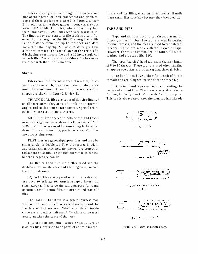
Taps and dies are used to cut threads in metal,plastics, or hard rubber. The taps are used for cuttinginternal threads, and the dies are used to cut externalthreads. There are many different types of taps.However, the most common are the taper, plug, bot-toming, and pipe taps (fig. 2-9).
The taper (starting) hand tap has a chamfer lengthof 8 to 10 threads. These taps are used when startinga tapping operation and when tapping through boles.
Plug hand taps have a chamfer length of 3 to 5threads and are designed for use after the taper tap.
Bottoming hand taps are used for threading thebottom of a blind hole. They have a very short cham-fer length of only 1 to 1 1/2 threads for this purpose.This tap is always used after the plug tap has already
Figure 2-9.—Types of common taps.
2-7
been used. Both the taper and plug taps should pre-cede the use of the bottoming hand tap.
Pipe taps are used for pipe fittings and otherplaces where extremely tight fits are necessary. Thetap diameter, from end to end of the threaded portion,increases at the rate of 3/4 inch per foot. All thethreads on this tap do the cutting, as compared to thestraight taps where only the nonchamfered portiondoes the cutting.
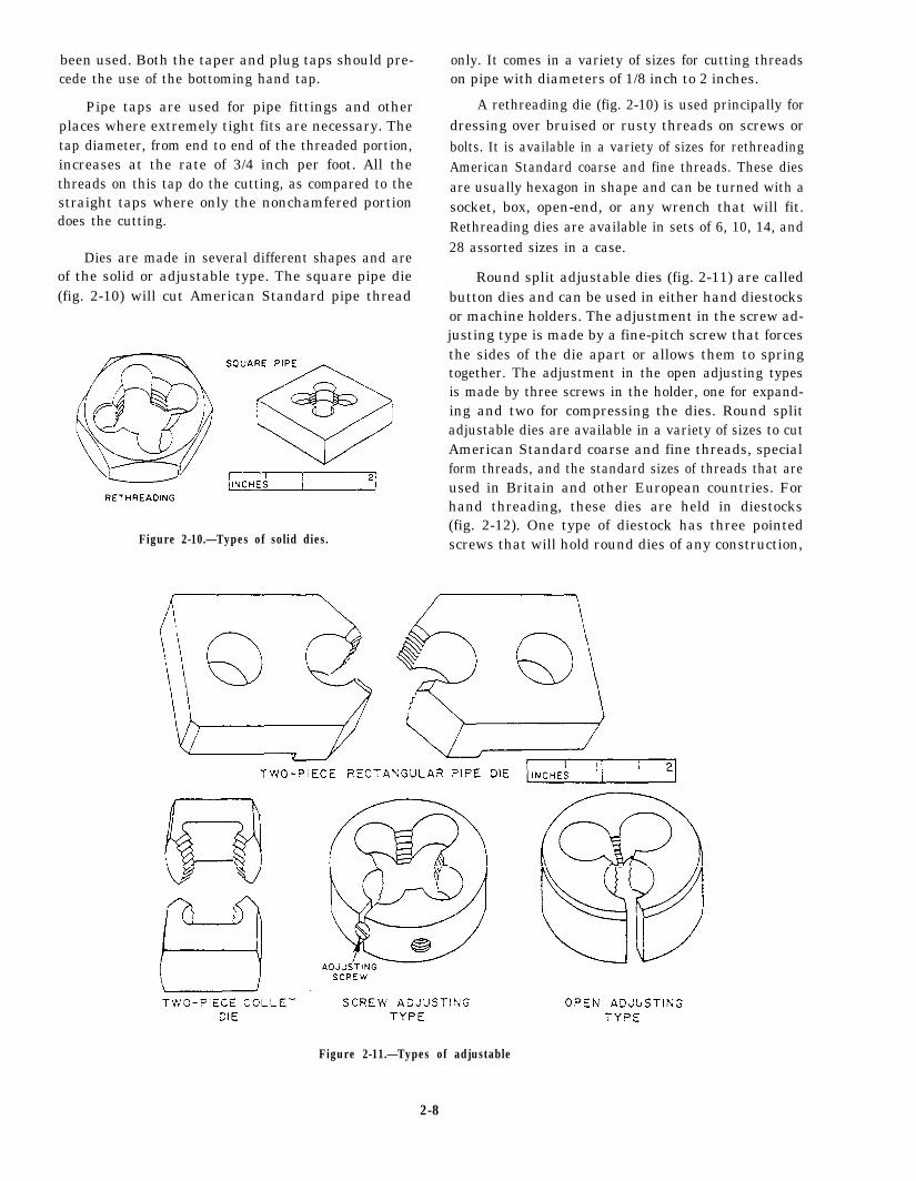
Dies are made in several different shapes and areof the solid or adjustable type. The square pipe die(fig. 2-10) will cut American Standard pipe thread
Figure 2-10.—Types of solid dies.
only. It comes in a variety of sizes for cutting threadson pipe with diameters of 1/8 inch to 2 inches.
A rethreading die (fig. 2-10) is used principally fordressing over bruised or rusty threads on screws orbolts. It is available in a variety of sizes for rethreadingAmerican Standard coarse and fine threads. These diesare usually hexagon in shape and can be turned with asocket, box, open-end, or any wrench that will fit.Rethreading dies are available in sets of 6, 10, 14, and28 assorted sizes in a case.
Round split adjustable dies (fig. 2-11) are calledbutton dies and can be used in either hand diestocksor machine holders. The adjustment in the screw ad-justing type is made by a fine-pitch screw that forcesthe sides of the die apart or allows them to springtogether. The adjustment in the open adjusting typesis made by three screws in the holder, one for expand-ing and two for compressing the dies. Round splitadjustable dies are available in a variety of sizes to cutAmerican Standard coarse and fine threads, specialform threads, and the standard sizes of threads that areused in Britain and other European countries. Forhand threading, these dies are held in diestocks(fig. 2-12). One type of diestock has three pointedscrews that will hold round dies of any construction,
Figure 2-11.—Types of adjustable
2-8
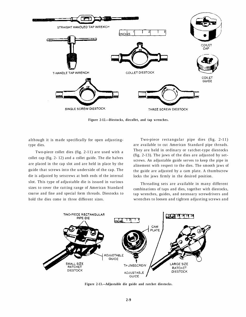
Figure 2-12.—Diestocks, diecollet, and tap wrenches.
although it is made specifically for open adjusting-type dies.
Two-piece collet dies (fig. 2-11) are used with acollet cap (fig. 2- 12) and a collet guide. The die halvesare placed in the cap slot and are held in place by the
guide that screws into the underside of the cap. The
die is adjusted by setscrews at both ends of the internal
slot. This type of adjustable die is issued in varioussizes to cover the cutting range of American Standardcoarse and fine and special form threads. Diestocks tohold the dies come in three different sizes.
Two-piece rectangular pipe dies (fig. 2-11)are available to cut American Standard pipe threads.They are held in ordinary or ratchet-type diestocks(fig. 2-13). The jaws of the dies are adjusted by set-screws. An adjustable guide serves to keep the pipe inalinement with respect to the dies. The smooth jaws ofthe guide are adjusted by a cam plate. A thumbscrewlocks the jaws firmly in the desired position.
Threading sets are available in many differentcombinations of taps and dies, together with diestocks,tap wrenches, guides, and necessary screwdrivers andwrenches to loosen and tighten adjusting screws and
Figure 2-13.—Adjustable die guide and ratchet diestocks.
2-9
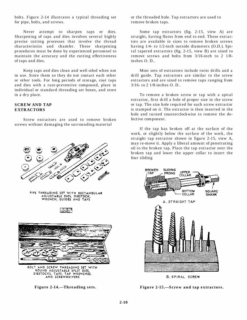
bolts. Figure 2-14 illustrates a typical threading setfor pipe, bolts, and screws.
Never attempt to sharpen taps or dies.Sharpening of taps and dies involves several highlyprecise cutting processes that involve the threadcharacteristics and chamfer. These sharpeningprocedures must be done by experienced personnel tomaintain the accuracy and the cutting effectivenessof taps and dies.
Keep taps and dies clean and well oiled when notin use. Store them so they do not contact each otheror other tools. For long periods of storage, coat tapsand dies with a rust-preventive compound, place inindividual or standard threading set boxes, and storein a dry place.
SCREW AND TAPEXTRACTORS
Screw extractors are used to remove brokenscrews without damaging the surrounding material
Figure 2-14.—Threading sets.
or the threaded hole. Tap extractors are used toremove broken taps.
Some tap extractors (fig. 2-15, view A) arestraight, having flutes from end to end. These extrac-tors are available in sizes to remove broken screwshaving 1/4- to 1/2-inch outside diameters (O.D.). Spi-ral tapered extractors (fig. 2-15, view B) are sized toremove screws and bolts from 3/16-inch to 2 1/8-inches O. D..
Most sets of extractors include twist drills and adrill guide. Tap extractors are similar to the screwextractors and are sized to remove taps ranging from3/16- to 2 1/8-inches O. D..
To remove a broken screw or tap with a spiralextractor, first drill a hole of proper size in the screwor tap. The size hole required for each screw extractoris stamped on it. The extractor is then inserted in thehole and turned counterclockwise to remove the de-fective component.
If the tap has broken off at the surface of thework, or slightly below the surface of the work, thestraight tap extractor shown in figure 2-15, view A,may re-move it. Apply a liberal amount of penetratingoil to the broken tap. Place the tap extractor over thebroken tap and lower the upper collar to insert thefour sliding
Figure 2-15.—Screw and tap extractors.
2-10
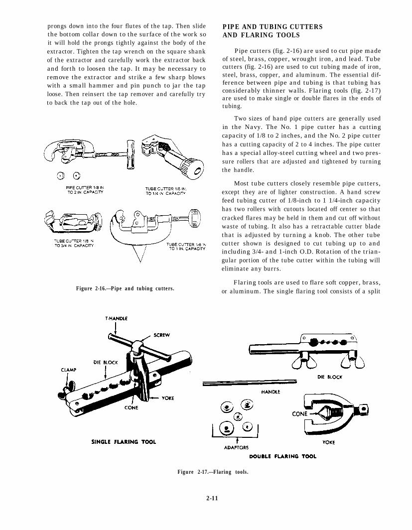
prongs down into the four flutes of the tap. Then slidethe bottom collar down to the surface of the work soit will hold the prongs tightly against the body of theextractor. Tighten the tap wrench on the square shankof the extractor and carefully work the extractor backand forth to loosen the tap. It may be necessary toremove the extractor and strike a few sharp blowswith a small hammer and pin punch to jar the taploose. Then reinsert the tap remover and carefully tryto back the tap out of the hole.
Figure 2-16.—Pipe and tubing cutters.
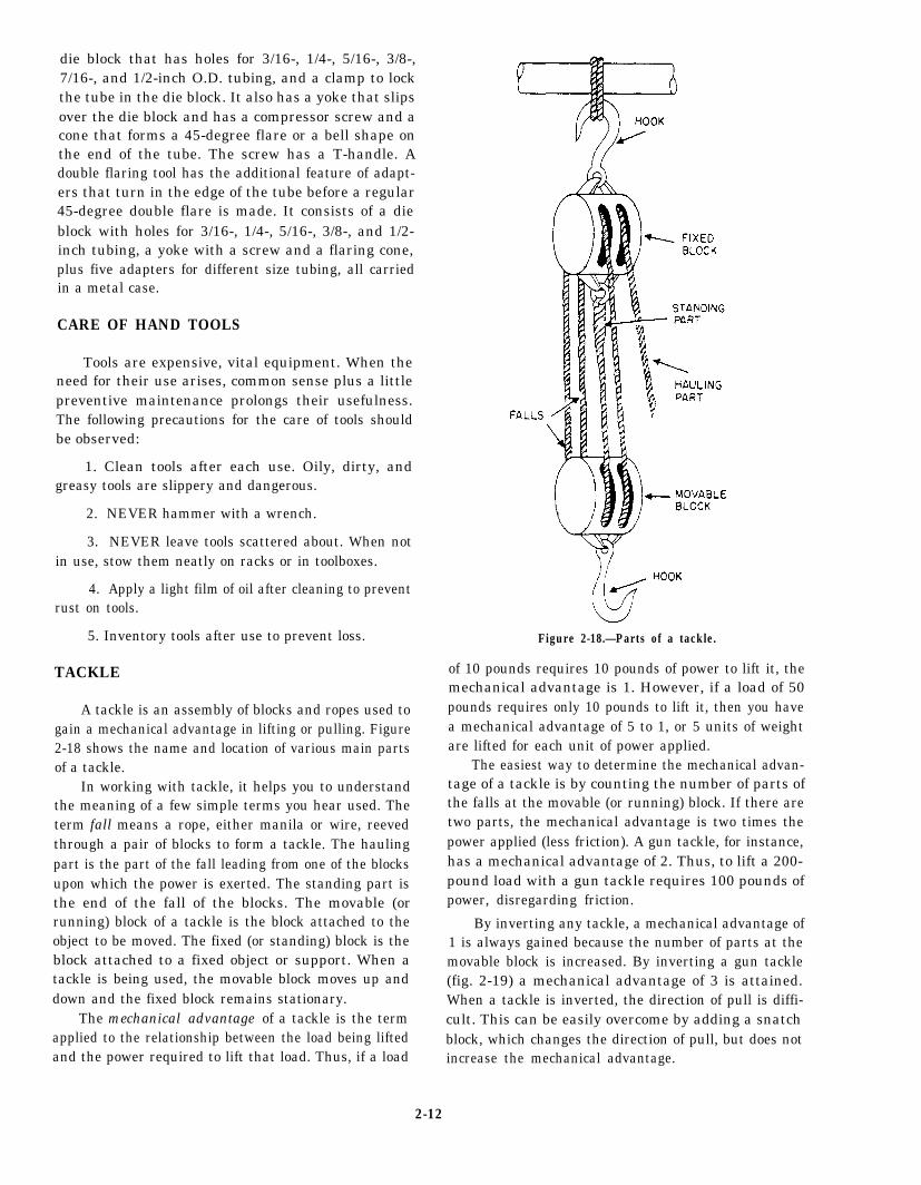
PIPE AND TUBING CUTTERSAND FLARING TOOLS
Pipe cutters (fig. 2-16) are used to cut pipe madeof steel, brass, copper, wrought iron, and lead. Tubecutters (fig. 2-16) are used to cut tubing made of iron,steel, brass, copper, and aluminum. The essential dif-ference between pipe and tubing is that tubing hasconsiderably thinner walls. Flaring tools (fig. 2-17)are used to make single or double flares in the ends oftubing.
Two sizes of hand pipe cutters are generally usedin the Navy. The No. 1 pipe cutter has a cuttingcapacity of 1/8 to 2 inches, and the No. 2 pipe cutterhas a cutting capacity of 2 to 4 inches. The pipe cutterhas a special alloy-steel cutting wheel and two pres-sure rollers that are adjusted and tightened by turningthe handle.
Most tube cutters closely resemble pipe cutters,except they are of lighter construction. A hand screwfeed tubing cutter of 1/8-inch to 1 1/4-inch capacityhas two rollers with cutouts located off center so thatcracked flares may be held in them and cut off withoutwaste of tubing. It also has a retractable cutter bladethat is adjusted by turning a knob. The other tubecutter shown is designed to cut tubing up to andincluding 3/4- and 1-inch O.D. Rotation of the trian-gular portion of the tube cutter within the tubing willeliminate any burrs.
Flaring tools are used to flare soft copper, brass,or aluminum. The single flaring tool consists of a split
Figure 2-17.—Flaring tools.
2-11
die block that has holes for 3/16-, 1/4-, 5/16-, 3/8-,7/16-, and 1/2-inch O.D. tubing, and a clamp to lockthe tube in the die block. It also has a yoke that slipsover the die block and has a compressor screw and acone that forms a 45-degree flare or a bell shape onthe end of the tube. The screw has a T-handle. Adouble flaring tool has the additional feature of adapt-ers that turn in the edge of the tube before a regular45-degree double flare is made. It consists of a dieblock with holes for 3/16-, 1/4-, 5/16-, 3/8-, and 1/2-inch tubing, a yoke with a screw and a flaring cone,plus five adapters for different size tubing, all carriedin a metal case.
CARE OF HAND TOOLS
Tools are expensive, vital equipment. When theneed for their use arises, common sense plus a littlepreventive maintenance prolongs their usefulness.The following precautions for the care of tools shouldbe observed:
1. Clean tools after each use. Oily, dirty, andgreasy tools are slippery and dangerous.
2. NEVER hammer with a wrench.
3. NEVER leave tools scattered about. When notin use, stow them neatly on racks or in toolboxes.
4. Apply a light film of oil after cleaning to preventrust on tools.
5. Inventory tools after use to prevent loss.
TACKLE
A tackle is an assembly of blocks and ropes used togain a mechanical advantage in lifting or pulling. Figure2-18 shows the name and location of various main partsof a tackle.
In working with tackle, it helps you to understandthe meaning of a few simple terms you hear used. Theterm fall means a rope, either manila or wire, reevedthrough a pair of blocks to form a tackle. The haulingpart is the part of the fall leading from one of the blocksupon which the power is exerted. The standing part isthe end of the fall of the blocks. The movable (orrunning) block of a tackle is the block attached to theobject to be moved. The fixed (or standing) block is theblock attached to a fixed object or support. When atackle is being used, the movable block moves up anddown and the fixed block remains stationary.
The mechanical advantage of a tackle is the termapplied to the relationship between the load being liftedand the power required to lift that load. Thus, if a load
Figure 2-18.—Parts of a tackle.
of 10 pounds requires 10 pounds of power to lift it, themechanical advantage is 1. However, if a load of 50pounds requires only 10 pounds to lift it, then you havea mechanical advantage of 5 to 1, or 5 units of weightare lifted for each unit of power applied.
The easiest way to determine the mechanical advan-tage of a tackle is by counting the number of parts ofthe falls at the movable (or running) block. If there aretwo parts, the mechanical advantage is two times thepower applied (less friction). A gun tackle, for instance,has a mechanical advantage of 2. Thus, to lift a 200-pound load with a gun tackle requires 100 pounds ofpower, disregarding friction.
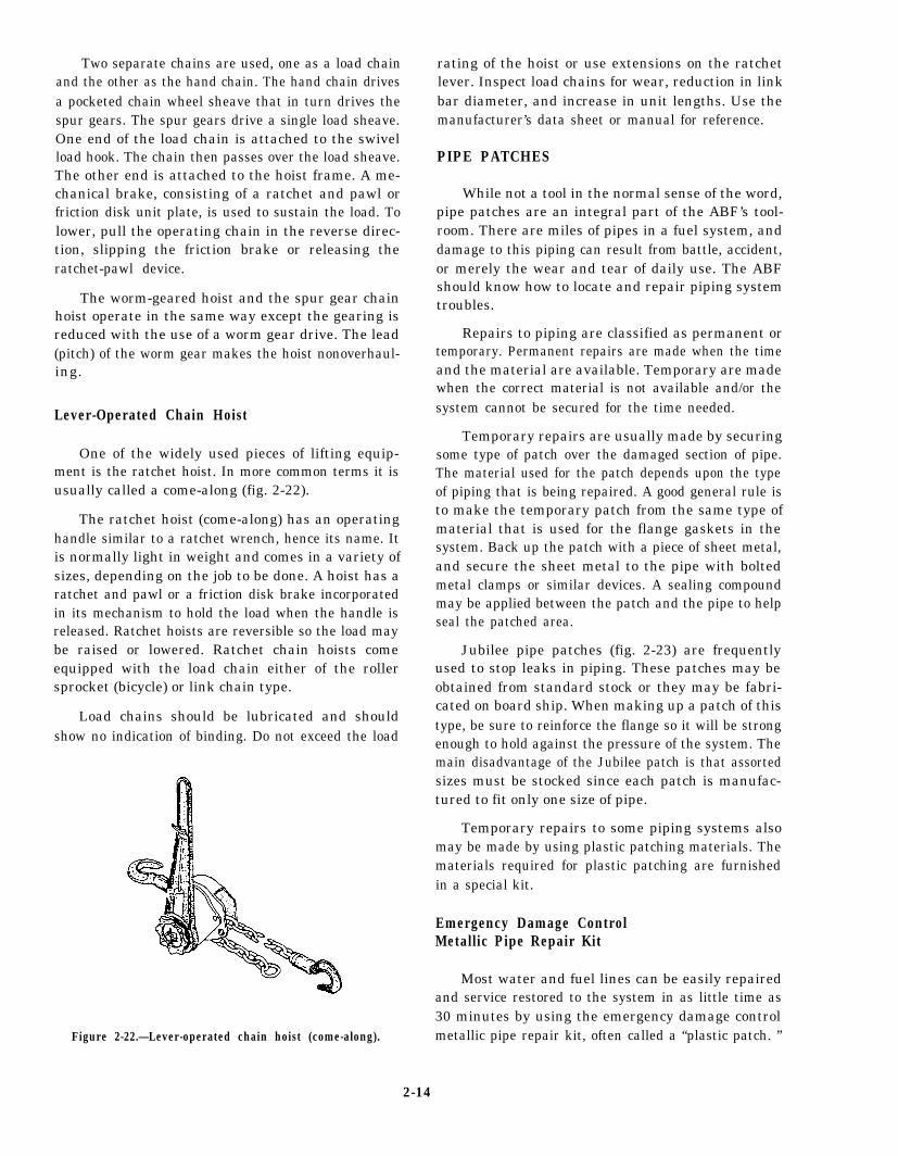
By inverting any tackle, a mechanical advantage of1 is always gained because the number of parts at themovable block is increased. By inverting a gun tackle(fig. 2-19) a mechanical advantage of 3 is attained.When a tackle is inverted, the direction of pull is diffi-cult. This can be easily overcome by adding a snatchblock, which changes the direction of pull, but does notincrease the mechanical advantage.
2-12
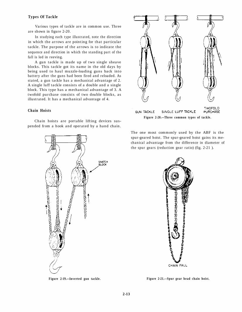
Types Of Tackle
Various types of tackle are in common use. Threeare shown in figure 2-20.
In studying each type illustrated, note the directionin which the arrows are pointing for that particulartackle. The purpose of the arrows is to indicate thesequence and direction in which the standing part of thefall is led in reeving.
A gun tackle is made up of two single sheaveblocks. This tackle got its name in the old days bybeing used to haul muzzle-loading guns back intobattery after the guns had been fired and reloaded. Asstated, a gun tackle has a mechanical advantage of 2.A single luff tackle consists of a double and a singleblock. This type has a mechanical advantage of 3. Atwofold purchase consists of two double blocks, asillustrated. It has a mechanical advantage of 4.
Chain Hoists
Chain hoists are portable lifting devices sus-pended from a hook and operated by a hand chain.
Figure 2-19.—Inverted gun tackle.
Figure 2-20.—Three common types of tackle.
The one most commonly used by the ABF is thespur-geared hoist. The spur-geared hoist gains its me-chanical advantage from the difference in diameter ofthe spur gears (reduction gear ratio) (fig. 2-21 ).
Figure 2-21.—Spur gear head chain hoist.
2-13
Two separate chains are used, one as a load chainand the other as the hand chain. The hand chain drivesa pocketed chain wheel sheave that in turn drives thespur gears. The spur gears drive a single load sheave.One end of the load chain is attached to the swivelload hook. The chain then passes over the load sheave.The other end is attached to the hoist frame. A me-chanical brake, consisting of a ratchet and pawl orfriction disk unit plate, is used to sustain the load. Tolower, pull the operating chain in the reverse direc-tion, slipping the friction brake or releasing theratchet-pawl device.
The worm-geared hoist and the spur gear chainhoist operate in the same way except the gearing isreduced with the use of a worm gear drive. The lead(pitch) of the worm gear makes the hoist nonoverhaul-ing.
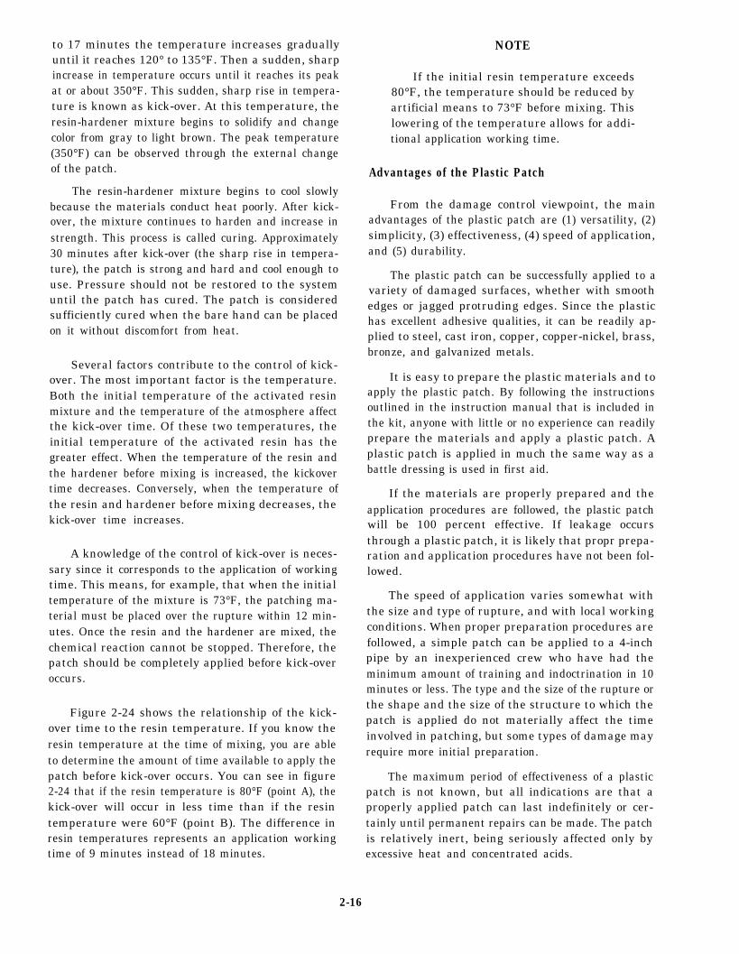
Lever-Operated Chain Hoist
One of the widely used pieces of lifting equip-ment is the ratchet hoist. In more common terms it isusually called a come-along (fig. 2-22).
The ratchet hoist (come-along) has an operatinghandle similar to a ratchet wrench, hence its name. Itis normally light in weight and comes in a variety ofsizes, depending on the job to be done. A hoist has aratchet and pawl or a friction disk brake incorporatedin its mechanism to hold the load when the handle isreleased. Ratchet hoists are reversible so the load maybe raised or lowered. Ratchet chain hoists comeequipped with the load chain either of the rollersprocket (bicycle) or link chain type.
Load chains should be lubricated and shouldshow no indication of binding. Do not exceed the load
Figure 2-22.—Lever-operated chain hoist (come-along).
rating of the hoist or use extensions on the ratchetlever. Inspect load chains for wear, reduction in linkbar diameter, and increase in unit lengths. Use themanufacturer’s data sheet or manual for reference.
PIPE PATCHES
While not a tool in the normal sense of the word,pipe patches are an integral part of the ABF’s tool-room. There are miles of pipes in a fuel system, anddamage to this piping can result from battle, accident,or merely the wear and tear of daily use. The ABFshould know how to locate and repair piping systemtroubles.
Repairs to piping are classified as permanent ortemporary. Permanent repairs are made when the timeand the material are available. Temporary are madewhen the correct material is not available and/or thesystem cannot be secured for the time needed.
Temporary repairs are usually made by securingsome type of patch over the damaged section of pipe.The material used for the patch depends upon the typeof piping that is being repaired. A good general rule isto make the temporary patch from the same type ofmaterial that is used for the flange gaskets in thesystem. Back up the patch with a piece of sheet metal,and secure the sheet metal to the pipe with boltedmetal clamps or similar devices. A sealing compoundmay be applied between the patch and the pipe to helpseal the patched area.
Jubilee pipe patches (fig. 2-23) are frequentlyused to stop leaks in piping. These patches may beobtained from standard stock or they may be fabri-cated on board ship. When making up a patch of thistype, be sure to reinforce the flange so it will be strongenough to hold against the pressure of the system. Themain disadvantage of the Jubilee patch is that assortedsizes must be stocked since each patch is manufac-tured to fit only one size of pipe.
Temporary repairs to some piping systems alsomay be made by using plastic patching materials. Thematerials required for plastic patching are furnishedin a special kit.
Emergency Damage ControlMetallic Pipe Repair Kit
Most water and fuel lines can be easily repairedand service restored to the system in as little time as30 minutes by using the emergency damage controlmetallic pipe repair kit, often called a “plastic patch. ”
2-14
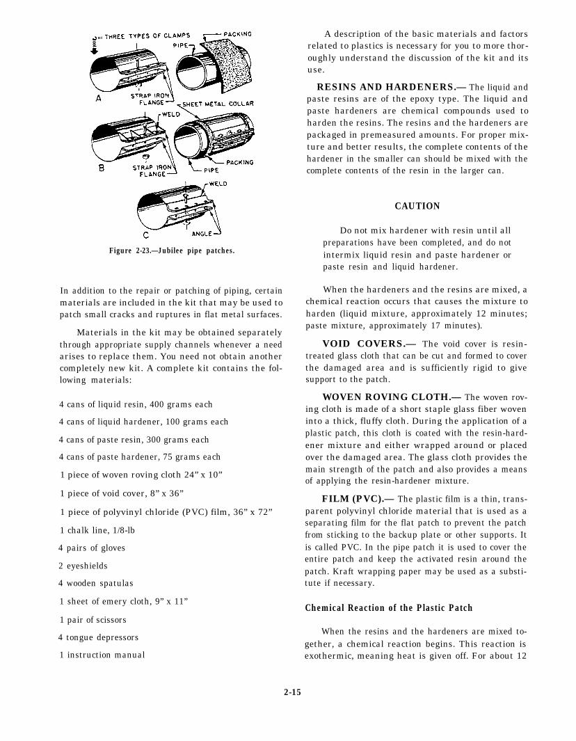
Figure 2-23.—Jubilee pipe patches.
In addition to the repair or patching of piping, certainmaterials are included in the kit that may be used topatch small cracks and ruptures in flat metal surfaces.
Materials in the kit may be obtained separatelythrough appropriate supply channels whenever a needarises to replace them. You need not obtain anothercompletely new kit. A complete kit contains the fol-lowing materials:
4 cans of liquid resin, 400 grams each
4 cans of liquid hardener, 100 grams each
4 cans of paste resin, 300 grams each
4 cans of paste hardener, 75 grams each
1 piece of woven roving cloth 24” x 10”
1 piece of void cover, 8” x 36”
1 piece of polyvinyl chloride (PVC) film, 36” x 72”
1 chalk line, 1/8-lb
4 pairs of gloves
2 eyeshields
4 wooden spatulas
A description of the basic materials and factorsrelated to plastics is necessary for you to more thor-oughly understand the discussion of the kit and itsuse.
RESINS AND HARDENERS.— The liquid andpaste resins are of the epoxy type. The liquid andpaste hardeners are chemical compounds used toharden the resins. The resins and the hardeners arepackaged in premeasured amounts. For proper mix-ture and better results, the complete contents of thehardener in the smaller can should be mixed with thecomplete contents of the resin in the larger can.
CAUTION
Do not mix hardener with resin until allpreparations have been completed, and do notintermix liquid resin and paste hardener orpaste resin and liquid hardener.
When the hardeners and the resins are mixed, achemical reaction occurs that causes the mixture toharden (liquid mixture, approximately 12 minutes;paste mixture, approximately 17 minutes).
VOID COVERS.— The void cover is resin-treated glass cloth that can be cut and formed to coverthe damaged area and is sufficiently rigid to givesupport to the patch.
WOVEN ROVING CLOTH.— The woven rov-ing cloth is made of a short staple glass fiber woveninto a thick, fluffy cloth. During the application of aplastic patch, this cloth is coated with the resin-hard-ener mixture and either wrapped around or placedover the damaged area. The glass cloth provides themain strength of the patch and also provides a meansof applying the resin-hardener mixture.
FILM (PVC).— The plastic film is a thin, trans-parent polyvinyl chloride material that is used as aseparating film for the flat patch to prevent the patchfrom sticking to the backup plate or other supports. Itis called PVC. In the pipe patch it is used to cover theentire patch and keep the activated resin around thepatch. Kraft wrapping paper may be used as a substi-tute if necessary.
1 sheet of emery cloth, 9” x 11”Chemical Reaction of the Plastic Patch
1 pair of scissors
4 tongue depressorsWhen the resins and the hardeners are mixed to-
gether, a chemical reaction begins. This reaction is1 instruction manual exothermic, meaning heat is given off. For about 12
2-15
to 17 minutes the temperature increases graduallyuntil it reaches 120° to 135°F. Then a sudden, sharpincrease in temperature occurs until it reaches its peakat or about 350°F. This sudden, sharp rise in tempera-ture is known as kick-over. At this temperature, theresin-hardener mixture begins to solidify and changecolor from gray to light brown. The peak temperature(350°F) can be observed through the external changeof the patch.
The resin-hardener mixture begins to cool slowlybecause the materials conduct heat poorly. After kick-over, the mixture continues to harden and increase instrength. This process is called curing. Approximately30 minutes after kick-over (the sharp rise in tempera-ture), the patch is strong and hard and cool enough touse. Pressure should not be restored to the systemuntil the patch has cured. The patch is consideredsufficiently cured when the bare hand can be placedon it without discomfort from heat.
Several factors contribute to the control of kick-over. The most important factor is the temperature.Both the initial temperature of the activated resinmixture and the temperature of the atmosphere affectthe kick-over time. Of these two temperatures, theinitial temperature of the activated resin has thegreater effect. When the temperature of the resin andthe hardener before mixing is increased, the kickovertime decreases. Conversely, when the temperature ofthe resin and hardener before mixing decreases, thekick-over time increases.
A knowledge of the control of kick-over is neces-sary since it corresponds to the application of workingtime. This means, for example, that when the initialtemperature of the mixture is 73°F, the patching ma-terial must be placed over the rupture within 12 min-utes. Once the resin and the hardener are mixed, thechemical reaction cannot be stopped. Therefore, thepatch should be completely applied before kick-overoccurs.
Figure 2-24 shows the relationship of the kick-over time to the resin temperature. If you know theresin temperature at the time of mixing, you are ableto determine the amount of time available to apply thepatch before kick-over occurs. You can see in figure2-24 that if the resin temperature is 80°F (point A), thekick-over will occur in less time than if the resintemperature were 60°F (point B). The difference inresin temperatures represents an application workingtime of 9 minutes instead of 18 minutes.
NOTE
If the initial resin temperature exceeds80°F, the temperature should be reduced byartificial means to 73°F before mixing. Thislowering of the temperature allows for addi-tional application working time.
Advantages of the Plastic Patch
From the damage control viewpoint, the mainadvantages of the plastic patch are (1) versatility, (2)simplicity, (3) effectiveness, (4) speed of application,and (5) durability.
The plastic patch can be successfully applied to avariety of damaged surfaces, whether with smoothedges or jagged protruding edges. Since the plastichas excellent adhesive qualities, it can be readily ap-plied to steel, cast iron, copper, copper-nickel, brass,bronze, and galvanized metals.
It is easy to prepare the plastic materials and toapply the plastic patch. By following the instructionsoutlined in the instruction manual that is included inthe kit, anyone with little or no experience can readilyprepare the materials and apply a plastic patch. Aplastic patch is applied in much the same way as abattle dressing is used in first aid.
If the materials are properly prepared and theapplication procedures are followed, the plastic patchwill be 100 percent effective. If leakage occursthrough a plastic patch, it is likely that propr prepa-ration and application procedures have not been fol-lowed.
The speed of application varies somewhat withthe size and type of rupture, and with local workingconditions. When proper preparation procedures arefollowed, a simple patch can be applied to a 4-inchpipe by an inexperienced crew who have had theminimum amount of training and indoctrination in 10minutes or less. The type and the size of the rupture orthe shape and the size of the structure to which thepatch is applied do not materially affect the timeinvolved in patching, but some types of damage mayrequire more initial preparation.
The maximum period of effectiveness of a plasticpatch is not known, but all indications are that aproperly applied patch can last indefinitely or cer-tainly until permanent repairs can be made. The patchis relatively inert, being seriously affected only byexcessive heat and concentrated acids.
2-16
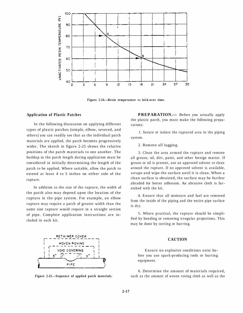
Figure 2-24.—Resin temperature vs kick-over time.
Application of Plastic Patches
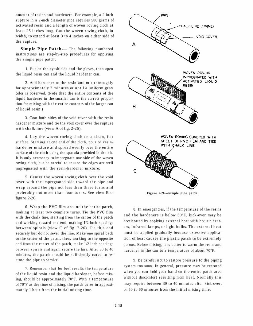
In the following discussion on applying differenttypes of plastic patches (simple, elbow, severed, andothers) you can readily see that as the individual patchmaterials are applied, the patch becomes progressivelywider. The sketch in figure 2-25 shows the relativepositions of the patch materials to one another. Thebuildup in the patch length during application must beconsidered in initially determining the length of thepatch to be applied. Where suitable, allow the patch toextend at least 4 to 5 inches on either side of therupture.
In addition to the size of the rupture, the width ofthe patch also may depend upon the location of therupture in the pipe system. For example, an elbowrupture may require a patch of greater width than thesame size rupture would require in a straight sectionof pipe. Complete application instructions are in-cluded in each kit.
Figure 2-25.—Sequence of applied patch materials.
PREPARATION.— Before you actually applythe plastic patch, you must make the following prepa-rations:
1. Secure or isolate the ruptured area in the pipingsystem.
2. Remove all lagging.
3. Clean the area around the rupture and removeall grease, oil, dirt, paint, and other foreign matter. Ifgrease or oil is present, use an approved solvent to cleanaround the rupture. If no approved solvent is available,scrape and wipe the surface until it is clean. When aclean surface is obtained, the surface may be furtherabraded for better adhesion. An abrasive cloth is fur-nished with the kit.
4. Ensure that all moisture and fuel are removedfrom the inside of the piping and the entire pipe surfaceis dry.
5. Where practical, the rupture should be simpli-fied by bending or removing irregular projections. Thismay be done by cutting or burring.
CAUTION
Ensure no explosive conditions exist be-fore you use spark-producing tools or burringequipment.
6. Determine the amount of materials required,such as the amount of woven roving cloth as well as the
2-17
amount of resins and hardeners. For example, a 2-inchrupture in a 2-inch diameter pipe requires 500 grams ofactivated resin and a length of woven roving cloth atleast 25 inches long. Cut the woven roving cloth, inwidth, to extend at least 3 to 4 inches on either side ofthe rupture.
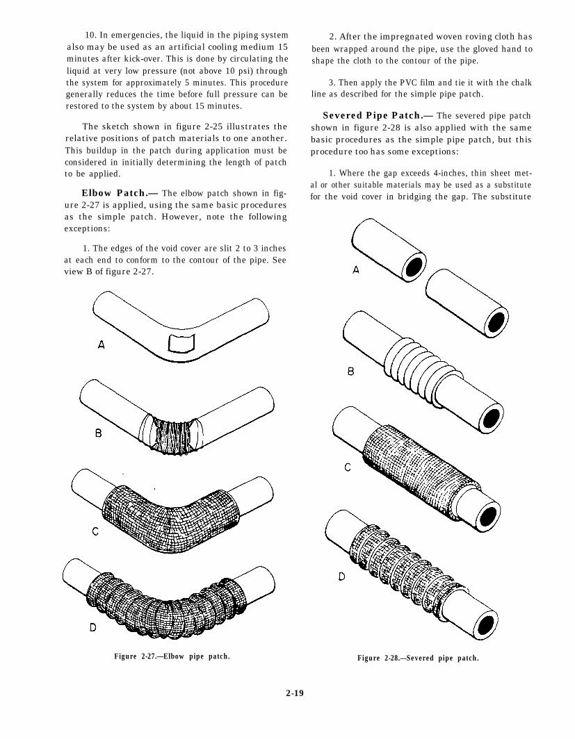
Simple Pipe Patch.— The following numberedinstructions are step-by-step procedures for applyingthe simple pipe patch;
1. Put on the eyeshields and the gloves, then openthe liquid resin can and the liquid hardener can.
2. Add hardener to the resin and mix thoroughlyfor approximately 2 minutes or until a uniform graycolor is observed. (Note that the entire contents of theliquid hardener in the smaller can is the correct propor-tion for mixing with the entire contents of the larger canof liquid resin.)
3. Coat both sides of the void cover with the resinhardener mixture and tie the void cover over the rupturewith chalk line (view A of fig. 2-26).
4. Lay the woven roving cloth on a clean, flatsurface. Starting at one end of the cloth, pour on resin-hardener mixture and spread evenly over the entiresurface of the cloth using the spatula provided in the kit.It is only necessary to impregnate one side of the wovenroving cloth, but be careful to ensure the edges are wellimpregnated with the resin-hardener mixture.
5. Center the woven roving cloth over the voidcover with the impregnated side toward the pipe andwrap around the pipe not less than three turns andpreferably not more than four turns. See view B offigure 2-26.
6. Wrap the PVC film around the entire patch,making at least two complete turns. Tie the PVC filmwith the chalk line, starting from the center of the patchand working toward one end, making 1/2-inch spacingsbetween spirals (view C of fig. 2-26). Tie this endsecurely but do not sever the line. Make one spiral backto the center of the patch, then, working to the oppositeend from the center of the patch, make 1/2-inch spacingsbetween spirals and again secure the line. After 30 to 40minutes, the patch should be sufficiently cured to re-store the pipe to service.
7. Remember that for best results the temperatureof the liquid resin and the liquid hardener, before mix-ing, should be approximately 70°F. With a temperatureof 70°F at the time of mixing, the patch cures in approxi-mately 1 hour from the initial mixing time.
Figure 2-26.—Simple pipe patch.
8. In emergencies, if the temperature of the resinsand the hardeners is below 50°F, kick-over may beaccelerated by applying external heat with hot air heat-ers, infrared lamps, or light bulbs. The external heatmust be applied gradually because excessive applica-tion of heat causes the plastic patch to be extremely
porous. Before mixing, it is better to warm the resin andhardener in the can to a temperature of about 70°F.
9. Be careful not to restore pressure to the pipingsystem too soon. In general, pressure may be restoredwhen you can hold your hand on the entire patch areawithout discomfort resulting from heat. Normally this
may require between 30 to 40 minutes after kick-over,or 50 to 60 minutes from the initial mixing time.
2-18
10. In emergencies, the liquid in the piping systemalso may be used as an artificial cooling medium 15minutes after kick-over. This is done by circulating theliquid at very low pressure (not above 10 psi) throughthe system for approximately 5 minutes. This proceduregenerally reduces the time before full pressure can berestored to the system by about 15 minutes.
The sketch shown in figure 2-25 illustrates therelative positions of patch materials to one another.This buildup in the patch during application must beconsidered in initially determining the length of patchto be applied.
Elbow Patch.— The elbow patch shown in fig-ure 2-27 is applied, using the same basic proceduresas the simple patch. However, note the followingexceptions:
1. The edges of the void cover are slit 2 to 3 inchesat each end to conform to the contour of the pipe. Seeview B of figure 2-27.
2. After the impregnated woven roving cloth hasbeen wrapped around the pipe, use the gloved hand toshape the cloth to the contour of the pipe.
3. Then apply the PVC film and tie it with the chalkline as described for the simple pipe patch.
Severed Pipe Patch.— The severed pipe patchshown in figure 2-28 is also applied with the samebasic procedures as the simple pipe patch, but thisprocedure too has some exceptions:
1. Where the gap exceeds 4-inches, thin sheet met-al or other suitable materials may be used as a substitutefor the void cover in bridging the gap. The substitute
Figure 2-27.—Elbow pipe patch.
2-19
Figure 2-28.—Severed pipe patch.
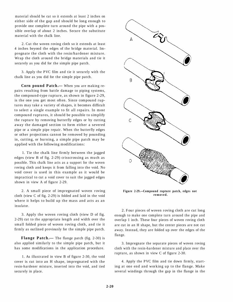
material should be cut so it extends at least 2 inches oneither side of the gap and should be long enough toprovide one complete turn around the pipe with a pos-sible overlap of about 2 inches. Secure the substitutematerial with the chalk line.
2. Cut the woven roving cloth so it extends at least4 inches beyond the edges of the bridge material. Im-pregnate the cloth with the resin/hardener mixture.Wrap the cloth around the bridge materials and tie itsecurely as you did for the simple pipe patch.
3. Apply the PVC film and tie it securely with thechalk line as you did for the simple pipe patch.
Corn pound Patch.— When you are making re-pairs resulting from battle damage to piping systems,the compound-type rupture, as shown in figure 2-29,is the one you get most often. Since compound rup-tures may take a variety of shapes, it becomes difficultto select a single example to fit all repairs. In mostcompound ruptures, it should be possible to simplifythe rupture by removing butterfly edges or by cuttingaway the damaged section to form either a severedpipe or a simple pipe repair. When the butterfly edgesor other projections cannot be removed by poundingin, cutting, or burning, a simple pipe patch may beapplied with the following modifications:
1. Tie the chalk line firmly between the jaggededges (view B of fig. 2-29) crisscrossing as much aspossible. This chalk line acts as a support for the wovenroving cloth and keeps it from falling into the void. Novoid cover is used in this example as it would beimpractical to cut a void cover to suit the jagged edgesshown in view A of figure 2-29.
2. A small piece of impregnated woven rovingcloth (view C of fig. 2-29) is folded and laid in the voidwhere it helps to build up the mass and acts as aninsulator.
3. Apply the woven roving cloth (view D of fig.2-29) cut to the appropriate length and width over thesmall folded piece of woven roving cloth, and tie itfirmly as outlined previously for the simple pipe patch.
Flange Patch.— The flange patch (fig. 2-30) isalso applied similarly to the simple pipe patch, but ithas some modifications in the application procedure.
1. As illustrated in view B of figure 2-30, the voidcover is cut into an H shape, impregnated with theresin-hardener mixture, inserted into the void, and tiedsecurely in place.
Figure 2-29.—Compound rupture patch, edges notremoved.
2. Four pieces of woven roving cloth are cut longenough to make one complete turn around the pipe andoverlap 1 inch. These four pieces of woven roving clothare cut in an H shape, but the center pieces are not cutaway. Instead, they are folded up over the edges of theflange.
3. Impregnate the separate pieces of woven rovingcloth with the resin-hardener mixture and place over therupture, as shown in view C of figure 2-30.
4. Apply the PVC film and tie down firmly, start-ing at one end and working up to the flange. Makeseveral windings through the gap in the flange in the
2-20
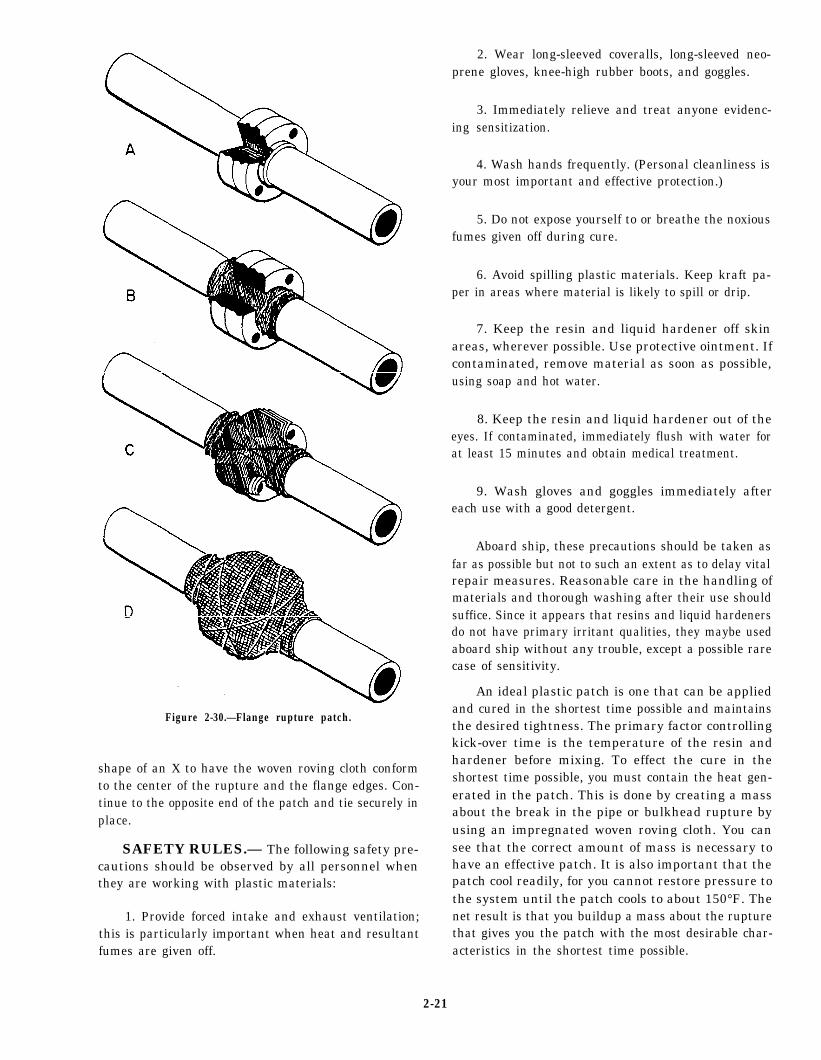
Figure 2-30.—Flange rupture patch.
shape of an X to have the woven roving cloth conformto the center of the rupture and the flange edges. Con-tinue to the opposite end of the patch and tie securely inplace.
SAFETY RULES.— The following safety pre-cautions should be observed by all personnel whenthey are working with plastic materials:
1. Provide forced intake and exhaust ventilation;this is particularly important when heat and resultantfumes are given off.
2. Wear long-sleeved coveralls, long-sleeved neo-prene gloves, knee-high rubber boots, and goggles.
3. Immediately relieve and treat anyone evidenc-ing sensitization.
4. Wash hands frequently. (Personal cleanliness isyour most important and effective protection.)
5. Do not expose yourself to or breathe the noxiousfumes given off during cure.
6. Avoid spilling plastic materials. Keep kraft pa-per in areas where material is likely to spill or drip.
7. Keep the resin and liquid hardener off skinareas, wherever possible. Use protective ointment. Ifcontaminated, remove material as soon as possible,using soap and hot water.
8. Keep the resin and liquid hardener out of theeyes. If contaminated, immediately flush with water forat least 15 minutes and obtain medical treatment.
9. Wash gloves and goggles immediately aftereach use with a good detergent.
Aboard ship, these precautions should be taken asfar as possible but not to such an extent as to delay vitalrepair measures. Reasonable care in the handling ofmaterials and thorough washing after their use shouldsuffice. Since it appears that resins and liquid hardenersdo not have primary irritant qualities, they maybe usedaboard ship without any trouble, except a possible rarecase of sensitivity.
An ideal plastic patch is one that can be appliedand cured in the shortest time possible and maintainsthe desired tightness. The primary factor controllingkick-over time is the temperature of the resin andhardener before mixing. To effect the cure in theshortest time possible, you must contain the heat gen-erated in the patch. This is done by creating a massabout the break in the pipe or bulkhead rupture byusing an impregnated woven roving cloth. You cansee that the correct amount of mass is necessary tohave an effective patch. It is also important that thepatch cool readily, for you cannot restore pressure tothe system until the patch cools to about 150°F. Thenet result is that you buildup a mass about the rupturethat gives you the patch with the most desirable char-acteristics in the shortest time possible.
2-21
PORTABLE POWER TOOLS
LEARNING OBJECTIVES: Identify portablepower tools used by the ABF. Explain the useand care of power tools. State the safety precau-tions required when using power tools.
ABFs are frequently required to use portablepower tools in the maintenance of assigned areas thatare exposed to the weather. Power tools, when usedproperly and efficiently, are an enormous time andmanpower saver, especially when a large painted orrusted surface requires scaling and represervation.Before using electric portable tools, be sure the propervoltage is supplied. This information can be found
Figure 2-31.—Portable electric sander.
on the nameplate permanently attached to the tool.Electric tools of all types used in the Navy are re-quired to have a proper ground capability. If doubtexists whether or not a good ground has been estab-lished, request the services of an Electrician’s Mate tocheck it out before applying power to the tool.NEVER VARY the manufacturer’s recommendedvoltage. SAFETY IS PARAMOUNT.
When pneumatic tools are used, the air supplypressure specified on the nameplate should always bemaintained. Insufficient air pressure causes the tool tofunction improperly. Excessive air pressure results indamage to the tool and the person operating the toolmay not be able to control it properly.
REMEMBER that tools can cut through rust,paint, metal, arms, and legs. Give your full attentionwhile operating any power tool and never distractanyone who is using power equipment.
PORTABLE ELECTRIC DRILL
The electric drill is a versatile item of equipment.It is probably used more than any other portable elec-tric tool. It can be used for drilling holes in wood ormetals, mixing paint, and buffing small items with theproper attachments, as well as a variety of other uses.
The average size electric drill has a 1/4-inch ca-pacity, with a three-fingered chuck tightened with achuck key. The chuck key is usually taped to theelectric cord about 18 inches from the drill itself toallow it to be used in the chuck without being re-moved from the cord. Heavier drills are larger inappearance and weight but have larger motors and
Figure 2-32.—Pneumatic chipping hammer.
2-22
chucks. In general, the larger the drill (and motor), theslower the rpm, which provides the needed extratorque to twist a greater size drill bit.
CAUTION
Unplug the drill before attempting totighten or remove drill bits.
PORTABLE ELECTRIC ORNEUMATIC OPERATED SANDER
The power sander (fig. 2-31) is one of the mostdesirable tools for scaling rust, removing paint, andsmoothing decks and bulkheads before painting. Thedesign of the portable power sander is much like thatof the electric drill motor with the addition of thesanding disk attached at right angles. The average sizedisk sander used in the Navy is either 7 or 9 inches.
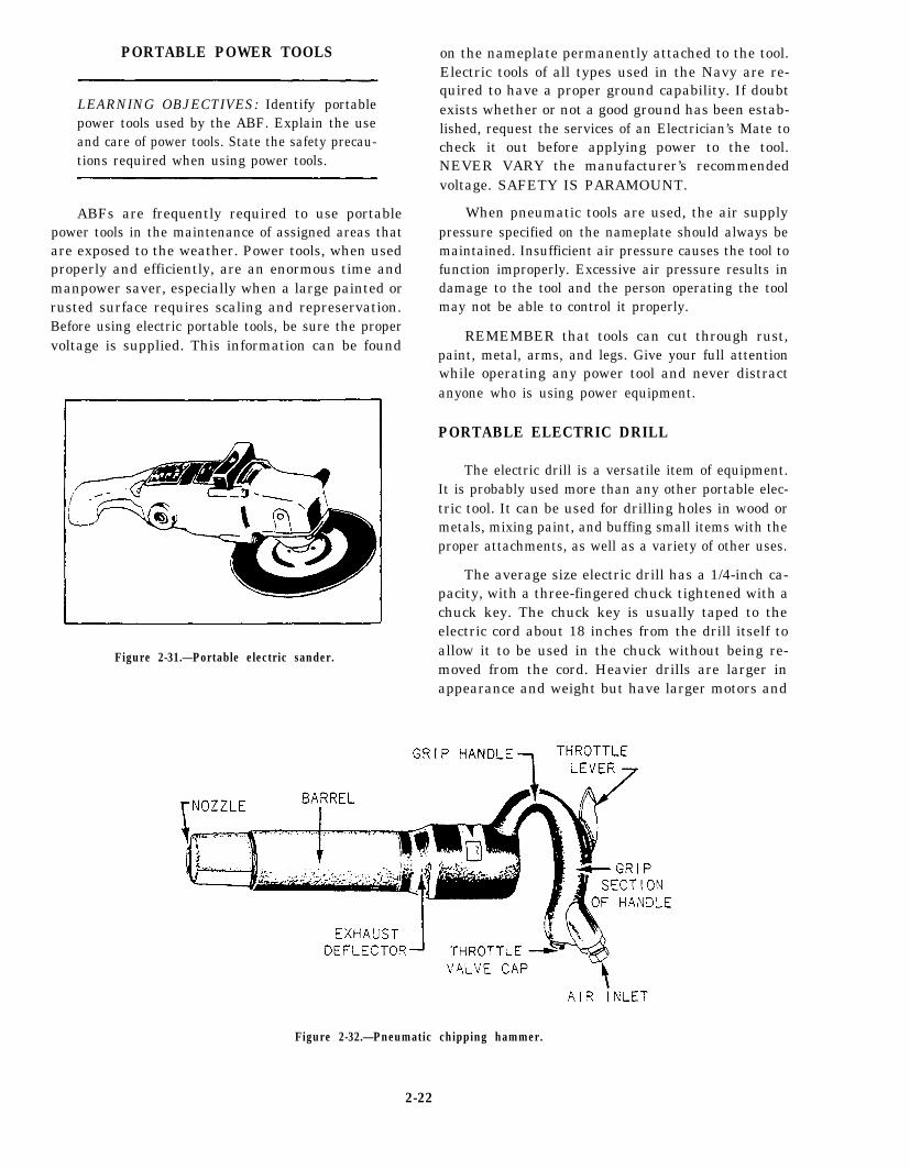
PNEUMATIC CHIPPINGHAMMER
The pneumatic chipping hammer (fig. 2-32) isanother tool useful to the ABF when scaling largeareas in preparation for repainting. Air pressure sup-ply should be maintained to the manufacturer’s rec-ommended working pressures found on the nameplateattached to the tool. Never point the pneumatic chip-ping hammer at another person or yourself while airpressure is supplied to the tool. Personal injury couldoccur if the chisel was expelled at high speed from thescaling hammer.
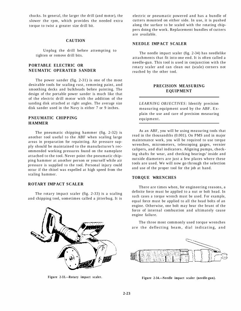
ROTARY IMPACT SCALER
The rotary impact scaler (fig. 2-33) is a scalingand chipping tool, sometimes called a jitterbug. It is
electric or pneumatic powered and has a bundle ofcutters mounted on either side. In use, it is pushedalong the surface to be scaled with the rotating chip-pers doing the work. Replacement bundles of cuttersare available.
NEEDLE IMPACT SCALER
The needle impact scaler (fig. 2-34) has needlelikeattachments that fit into one end. It is often called aneedle-gun. This tool is used in conjunction with therotary scaler and can clean out (scale) corners notreached by the other tool.
PRECISION MEASURINGEQUIPMENT
LEARNING OBJECTIVES: Identify precisionmeasuring equipment used by the ABF. Ex-plain the use and care of precision measuringequipment.
As an ABF, you will be using measuring tools thatread in the thousandths (0.001). On PMS and in majormaintenance work, you will be required to use torquewrenches, micrometers, telescoping gages, verniercalipers, and dial indicators. Aligning pumps, check-ing shafts for wear, and checking bearings’ inside andoutside diameters are just a few places where thesetools are used. We will now go through the selectionand use of the proper tool for the job at hand.
TORQUE WRENCHES
There are times when, for engineering reasons, adefinite force must be applied to a nut or bolt head. Insuch cases a torque wrench must be used. For example,equal force must be applied to all the head bolts of anengine. Otherwise, one bolt may bear the brunt of theforce of internal combustion and ultimately causeengine failure.
The three most commonly used torque wrenchesare the deflecting beam, dial indicating, and
Figure 2-33.—Rotary impact scaler.
2-23
Figure 2-34.—Needle impact scaler (needle-gun).
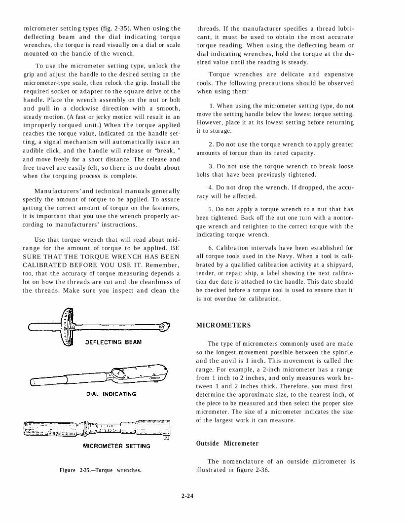
micrometer setting types (fig. 2-35). When using thedeflecting beam and the dial indicating torquewrenches, the torque is read visually on a dial or scalemounted on the handle of the wrench.
To use the micrometer setting type, unlock thegrip and adjust the handle to the desired setting on themicrometer-type scale, then relock the grip. Install therequired socket or adapter to the square drive of thehandle. Place the wrench assembly on the nut or boltand pull in a clockwise direction with a smooth,steady motion. (A fast or jerky motion will result in animproperly torqued unit.) When the torque appliedreaches the torque value, indicated on the handle set-ting, a signal mechanism will automatically issue anaudible click, and the handle will release or “break, ”and move freely for a short distance. The release andfree travel are easily felt, so there is no doubt aboutwhen the torquing process is complete.
Manufacturers’ and technical manuals generallyspecify the amount of torque to be applied. To assuregetting the correct amount of torque on the fasteners,it is important that you use the wrench properly ac-cording to manufacturers’ instructions.
Use that torque wrench that will read about mid-range for the amount of torque to be applied. BESURE THAT THE TORQUE WRENCH HAS BEENCALIBRATED BEFORE YOU USE IT. Remember,too, that the accuracy of torque measuring depends alot on how the threads are cut and the cleanliness ofthe threads. Make sure you inspect and clean the
Figure 2-35.—Torque wrenches.
threads. If the manufacturer specifies a thread lubri-cant, it must be used to obtain the most accuratetorque reading. When using the deflecting beam ordial indicating wrenches, hold the torque at the de-sired value until the reading is steady.
Torque wrenches are delicate and expensivetools. The following precautions should be observedwhen using them:
1. When using the micrometer setting type, do notmove the setting handle below the lowest torque setting.However, place it at its lowest setting before returningit to storage.
2. Do not use the torque wrench to apply greateramounts of torque than its rated capacity.
3. Do not use the torque wrench to break loosebolts that have been previously tightened.
4. Do not drop the wrench. If dropped, the accu-racy will be affected.
5. Do not apply a torque wrench to a nut that hasbeen tightened. Back off the nut one turn with a nontor-que wrench and retighten to the correct torque with theindicating torque wrench.
6. Calibration intervals have been established forall torque tools used in the Navy. When a tool is cali-brated by a qualified calibration activity at a shipyard,tender, or repair ship, a label showing the next calibra-tion due date is attached to the handle. This date shouldbe checked before a torque tool is used to ensure that itis not overdue for calibration.
MICROMETERS
The type of micrometers commonly used are madeso the longest movement possible between the spindleand the anvil is 1 inch. This movement is called therange. For example, a 2-inch micrometer has a rangefrom 1 inch to 2 inches, and only measures work be-tween 1 and 2 inches thick. Therefore, you must firstdetermine the approximate size, to the nearest inch, ofthe piece to be measured and then select the proper sizemicrometer. The size of a micrometer indicates the sizeof the largest work it can measure.
Outside Micrometer
The nomenclature of an outside micrometer isillustrated in figure 2-36.
2-24
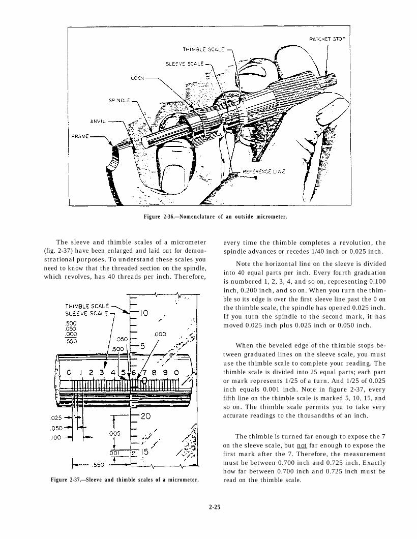
Figure 2-36.—Nomenclature of an outside micrometer.
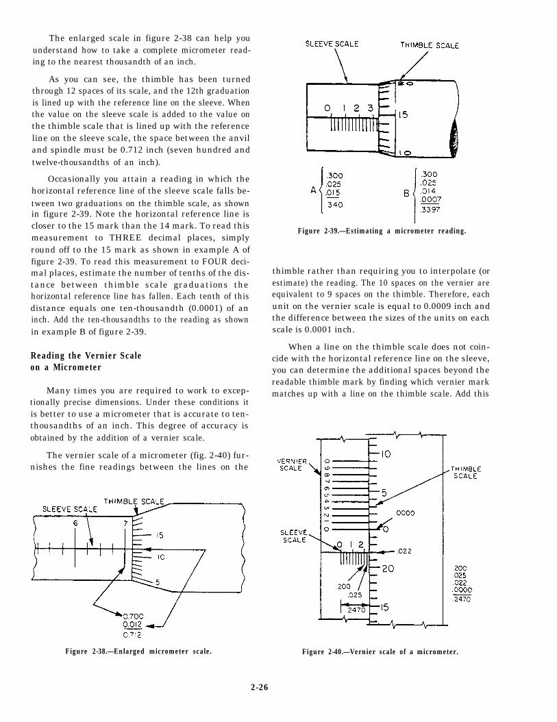
The sleeve and thimble scales of a micrometer every time the thimble completes a revolution, the(fig. 2-37) have been enlarged and laid out for demon-strational purposes. To understand these scales youneed to know that the threaded section on the spindle,which revolves, has 40 threads per inch. Therefore,
Figure 2-37.—Sleeve and thimble scales of a micrometer.
spindle advances or recedes 1/40 inch or 0.025 inch.
Note the horizontal line on the sleeve is dividedinto 40 equal parts per inch. Every fourth graduationis numbered 1, 2, 3, 4, and so on, representing 0.100inch, 0.200 inch, and so on. When you turn the thim-ble so its edge is over the first sleeve line past the 0 onthe thimble scale, the spindle has opened 0.025 inch.If you turn the spindle to the second mark, it hasmoved 0.025 inch plus 0.025 inch or 0.050 inch.
When the beveled edge of the thimble stops be-tween graduated lines on the sleeve scale, you mustuse the thimble scale to complete your reading. Thethimble scale is divided into 25 equal parts; each partor mark represents 1/25 of a turn. And 1/25 of 0.025inch equals 0.001 inch. Note in figure 2-37, everyfifth line on the thimble scale is marked 5, 10, 15, andso on. The thimble scale permits you to take veryaccurate readings to the thousandths of an inch.
The thimble is turned far enough to expose the 7on the sleeve scale, but not far enough to expose thefirst mark after the 7. Therefore, the measurementmust be between 0.700 inch and 0.725 inch. Exactlyhow far between 0.700 inch and 0.725 inch must beread on the thimble scale.
2-25
The enlarged scale in figure 2-38 can help youunderstand how to take a complete micrometer read-ing to the nearest thousandth of an inch.
As you can see, the thimble has been turnedthrough 12 spaces of its scale, and the 12th graduationis lined up with the reference line on the sleeve. Whenthe value on the sleeve scale is added to the value onthe thimble scale that is lined up with the referenceline on the sleeve scale, the space between the anviland spindle must be 0.712 inch (seven hundred andtwelve-thousandths of an inch).
Occasionally you attain a reading in which thehorizontal reference line of the sleeve scale falls be-tween two graduations on the thimble scale, as shownin figure 2-39. Note the horizontal reference line iscloser to the 15 mark than the 14 mark. To read thismeasurement to THREE decimal places, simplyround off to the 15 mark as shown in example A offigure 2-39. To read this measurement to FOUR deci-mal places, estimate the number of tenths of the dis-tance between thimble scale graduations thehorizontal reference line has fallen. Each tenth of thisdistance equals one ten-thousandth (0.0001) of aninch. Add the ten-thousandths to the reading as shownin example B of figure 2-39.
Reading the Vernier Scaleon a Micrometer
Many times you are required to work to excep-tionally precise dimensions. Under these conditions itis better to use a micrometer that is accurate to ten-thousandths of an inch. This degree of accuracy isobtained by the addition of a vernier scale.
The vernier scale of a micrometer (fig. 2-40) fur-nishes the fine readings between the lines on the
Figure 2-38.—Enlarged micrometer scale.
Figure 2-39.—Estimating a micrometer reading.
thimble rather than requiring you to interpolate (orestimate) the reading. The 10 spaces on the vernier areequivalent to 9 spaces on the thimble. Therefore, eachunit on the vernier scale is equal to 0.0009 inch andthe difference between the sizes of the units on eachscale is 0.0001 inch.
When a line on the thimble scale does not coin-cide with the horizontal reference line on the sleeve,you can determine the additional spaces beyond thereadable thimble mark by finding which vernier markmatches up with a line on the thimble scale. Add this
Figure 2-40.—Vernier scale of a micrometer.
2-26
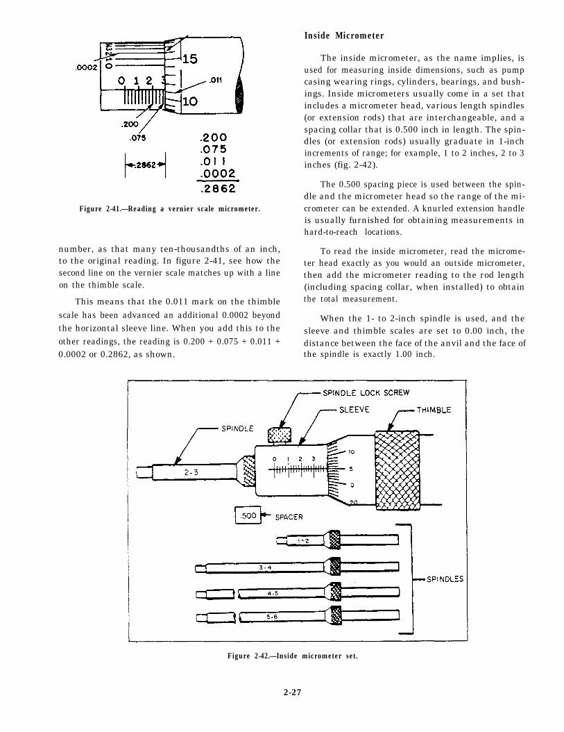
Figure 2-41.—Reading a vernier scale micrometer.
number, as that many ten-thousandths of an inch,to the original reading. In figure 2-41, see how thesecond line on the vernier scale matches up with a lineon the thimble scale.
This means that the 0.011 mark on the thimblescale has been advanced an additional 0.0002 beyondthe horizontal sleeve line. When you add this to theother readings, the reading is 0.200 + 0.075 + 0.011 +0.0002 or 0.2862, as shown.
Inside Micrometer
The inside micrometer, as the name implies, isused for measuring inside dimensions, such as pumpcasing wearing rings, cylinders, bearings, and bush-ings. Inside micrometers usually come in a set thatincludes a micrometer head, various length spindles(or extension rods) that are interchangeable, and aspacing collar that is 0.500 inch in length. The spin-dles (or extension rods) usually graduate in 1-inchincrements of range; for example, 1 to 2 inches, 2 to 3inches (fig. 2-42).
The 0.500 spacing piece is used between the spin-dle and the micrometer head so the range of the mi-crometer can be extended. A knurled extension handleis usually furnished for obtaining measurements inhard-to-reach locations.
To read the inside micrometer, read the microme-ter head exactly as you would an outside micrometer,then add the micrometer reading to the rod length(including spacing collar, when installed) to obtainthe total measurement.
When the 1- to 2-inch spindle is used, and thesleeve and thimble scales are set to 0.00 inch, thedistance between the face of the anvil and the face ofthe spindle is exactly 1.00 inch.
Figure 2-42.—Inside micrometer set.
2-27
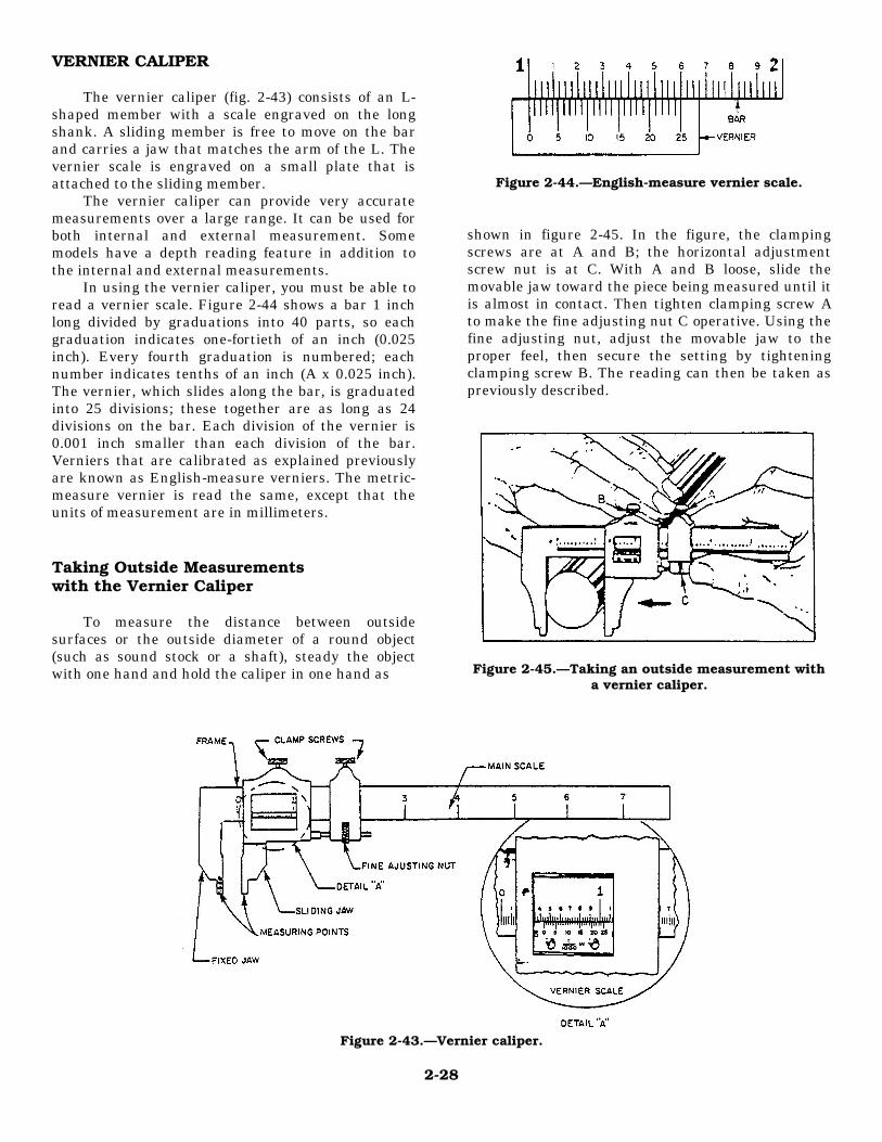
VERNIER CALIPER
The vernier caliper (fig. 2-43) consists of an L-shaped member with a scale engraved on the longshank. A sliding member is free to move on the barand carries a jaw that matches the arm of the L. Thevernier scale is engraved on a small plate that isattached to the sliding member.
The vernier caliper can provide very accuratemeasurements over a large range. It can be used forboth internal and external measurement. Somemodels have a depth reading feature in addition tothe internal and external measurements.
In using the vernier caliper, you must be able toread a vernier scale. Figure 2-44 shows a bar 1 inchlong divided by graduations into 40 parts, so eachgraduation indicates one-fortieth of an inch (0.025inch). Every fourth graduation is numbered; eachnumber indicates tenths of an inch (A x 0.025 inch).The vernier, which slides along the bar, is graduatedinto 25 divisions; these together are as long as 24divisions on the bar. Each division of the vernier is0.001 inch smaller than each division of the bar.Verniers that are calibrated as explained previouslyare known as English-measure verniers. The metric-measure vernier is read the same, except that theunits of measurement are in millimeters.
Taking Outside Measurementswith the Vernier Caliper
To measure the distance between outsidesurfaces or the outside diameter of a round object(such as sound stock or a shaft), steady the objectwith one hand and hold the caliper in one hand as
Figure 2-44.—English-measure vernier scale.
shown in figure 2-45. In the figure, the clampingscrews are at A and B; the horizontal adjustmentscrew nut is at C. With A and B loose, slide themovable jaw toward the piece being measured until itis almost in contact. Then tighten clamping screw Ato make the fine adjusting nut C operative. Using thefine adjusting nut, adjust the movable jaw to theproper feel, then secure the setting by tighteningclamping screw B. The reading can then be taken aspreviously described.
Figure 2-45.—Taking an outside measurement witha vernier caliper.
Figure 2-43.—Vernier caliper.
2-28
Taking Inside Measurementswith the Vernier Caliper
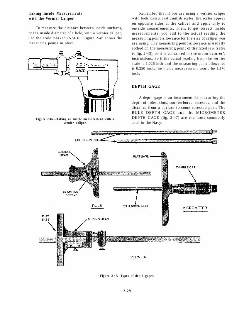
To measure the distance between inside surfaces,or the inside diameter of a hole, with a vernier caliper,use the scale marked INSIDE. Figure 2-46 shows themeasuring points in place.
Figure 2-46.—Taking an inside measurement with avernier caliper.
Remember that if you are using a vernier caliperwith both metric and English scales, the scales appearon opposite sides of the caliper and apply only tooutside measurements. Then, to get correct insidemeasurements, you add to the actual reading themeasuring point allowance for the size of caliper youare using. The measuring point allowance is usuallyetched on the measuring point of the fixed jaw (referto fig. 2-43), or it is contained in the manufacturer’sinstructions. So if the actual reading from the vernierscale is 1.026 inch and the measuring point allowanceis 0.250 inch, the inside measurement would be 1.276inch.
DEPTH GAGE
A depth gage is an instrument for measuring thedepth of holes, slots, counterbores, recesses, and thedistance from a surface to some recessed part. TheRULE DEPTH GAGE and the MICROMETERDEPTH GAGE (fig. 2-47) are the most commonlyused in the Navy.
Figure 2-47.—Types of depth gages.
2-29
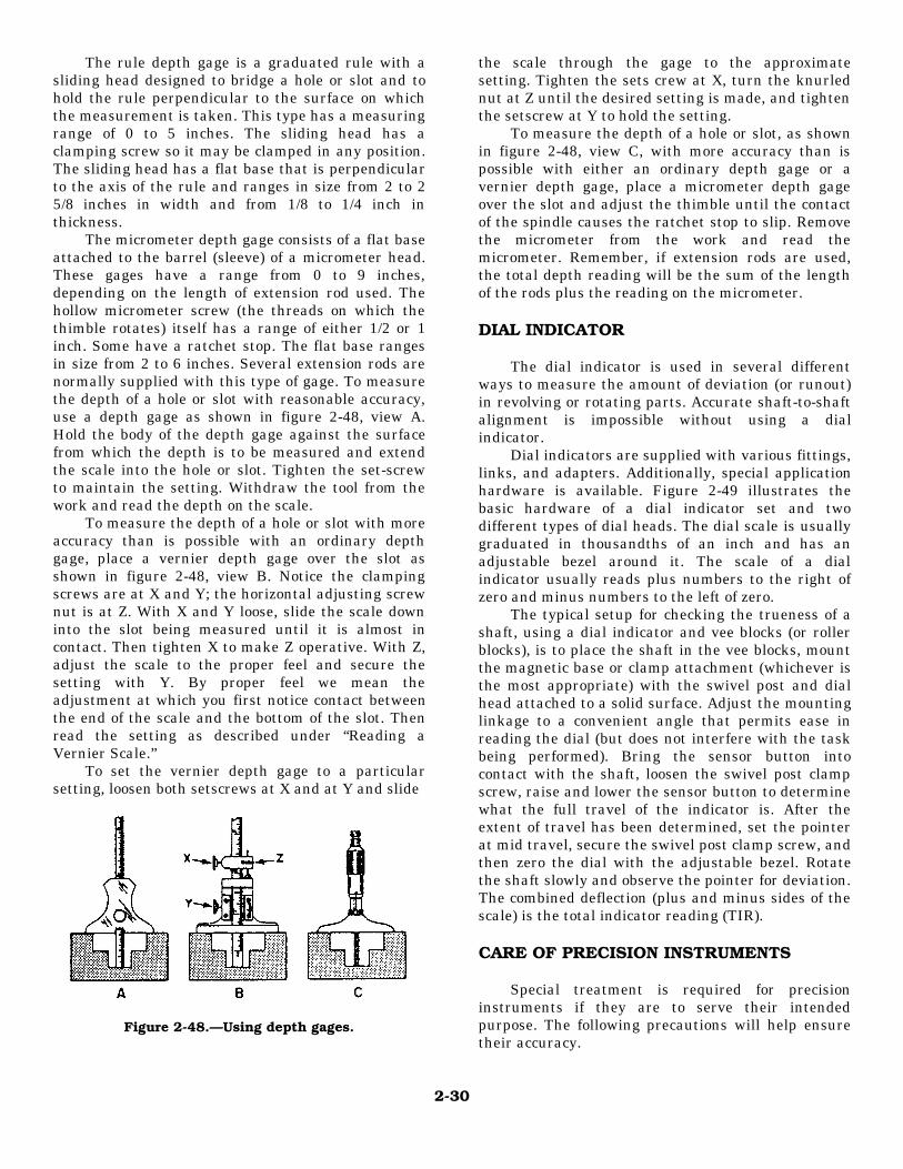
The rule depth gage is a graduated rule with asliding head designed to bridge a hole or slot and tohold the rule perpendicular to the surface on whichthe measurement is taken. This type has a measuringrange of 0 to 5 inches. The sliding head has aclamping screw so it may be clamped in any position.The sliding head has a flat base that is perpendicularto the axis of the rule and ranges in size from 2 to 25/8 inches in width and from 1/8 to 1/4 inch inthickness.
The micrometer depth gage consists of a flat baseattached to the barrel (sleeve) of a micrometer head.These gages have a range from 0 to 9 inches,depending on the length of extension rod used. Thehollow micrometer screw (the threads on which thethimble rotates) itself has a range of either 1/2 or 1inch. Some have a ratchet stop. The flat base rangesin size from 2 to 6 inches. Several extension rods arenormally supplied with this type of gage. To measurethe depth of a hole or slot with reasonable accuracy,use a depth gage as shown in figure 2-48, view A.Hold the body of the depth gage against the surfacefrom which the depth is to be measured and extendthe scale into the hole or slot. Tighten the set-screwto maintain the setting. Withdraw the tool from thework and read the depth on the scale.
To measure the depth of a hole or slot with moreaccuracy than is possible with an ordinary depthgage, place a vernier depth gage over the slot asshown in figure 2-48, view B. Notice the clampingscrews are at X and Y; the horizontal adjusting screwnut is at Z. With X and Y loose, slide the scale downinto the slot being measured until it is almost incontact. Then tighten X to make Z operative. With Z,adjust the scale to the proper feel and secure thesetting with Y. By proper feel we mean theadjustment at which you first notice contact betweenthe end of the scale and the bottom of the slot. Thenread the setting as described under “Reading aVernier Scale.”
To set the vernier depth gage to a particularsetting, loosen both setscrews at X and at Y and slide
Figure 2-48.—Using depth gages.
the scale through the gage to the approximatesetting. Tighten the sets crew at X, turn the knurlednut at Z until the desired setting is made, and tightenthe setscrew at Y to hold the setting.
To measure the depth of a hole or slot, as shownin figure 2-48, view C, with more accuracy than ispossible with either an ordinary depth gage or avernier depth gage, place a micrometer depth gageover the slot and adjust the thimble until the contactof the spindle causes the ratchet stop to slip. Removethe micrometer from the work and read themicrometer. Remember, if extension rods are used,the total depth reading will be the sum of the lengthof the rods plus the reading on the micrometer.
DIAL INDICATOR
The dial indicator is used in several differentways to measure the amount of deviation (or runout)in revolving or rotating parts. Accurate shaft-to-shaftalignment is impossible without using a dialindicator.
Dial indicators are supplied with various fittings,links, and adapters. Additionally, special applicationhardware is available. Figure 2-49 illustrates thebasic hardware of a dial indicator set and twodifferent types of dial heads. The dial scale is usuallygraduated in thousandths of an inch and has anadjustable bezel around it. The scale of a dialindicator usually reads plus numbers to the right ofzero and minus numbers to the left of zero.
The typical setup for checking the trueness of ashaft, using a dial indicator and vee blocks (or rollerblocks), is to place the shaft in the vee blocks, mountthe magnetic base or clamp attachment (whichever isthe most appropriate) with the swivel post and dialhead attached to a solid surface. Adjust the mountinglinkage to a convenient angle that permits ease inreading the dial (but does not interfere with the taskbeing performed). Bring the sensor button intocontact with the shaft, loosen the swivel post clampscrew, raise and lower the sensor button to determinewhat the full travel of the indicator is. After theextent of travel has been determined, set the pointerat mid travel, secure the swivel post clamp screw, andthen zero the dial with the adjustable bezel. Rotatethe shaft slowly and observe the pointer for deviation.The combined deflection (plus and minus sides of thescale) is the total indicator reading (TIR).
CARE OF PRECISION INSTRUMENTS
Special treatment is required for precisioninstruments if they are to serve their intendedpurpose. The following precautions will help ensuretheir accuracy.
2-30
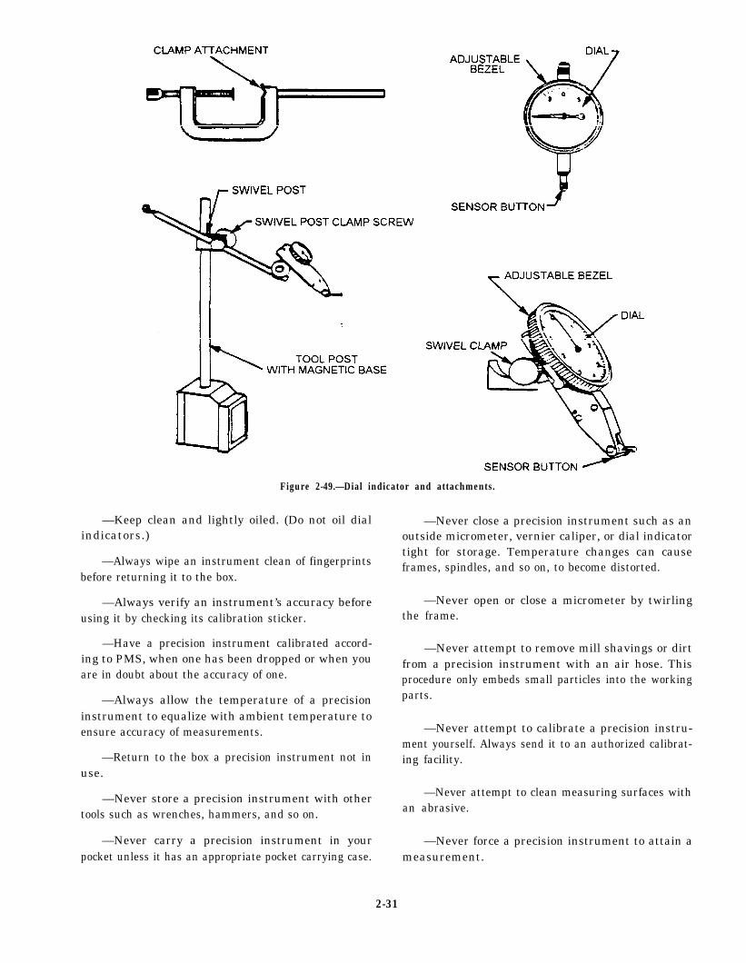
Figure 2-49.—Dial indicator and attachments.
—Keep clean and lightly oiled. (Do not oil dialindicators.)
—Always wipe an instrument clean of fingerprintsbefore returning it to the box.
—Always verify an instrument’s accuracy beforeusing it by checking its calibration sticker.
—Have a precision instrument calibrated accord-ing to PMS, when one has been dropped or when youare in doubt about the accuracy of one.
—Always allow the temperature of a precisioninstrument to equalize with ambient temperature toensure accuracy of measurements.
—Return to the box a precision instrument not inuse.
—Never store a precision instrument with othertools such as wrenches, hammers, and so on.
—Never carry a precision instrument in yourpocket unless it has an appropriate pocket carrying case.
—Never close a precision instrument such as anoutside micrometer, vernier caliper, or dial indicatortight for storage. Temperature changes can causeframes, spindles, and so on, to become distorted.
—Never open or close a micrometer by twirlingthe frame.
—Never attempt to remove mill shavings or dirtfrom a precision instrument with an air hose. Thisprocedure only embeds small particles into the workingparts.
—Never attempt to calibrate a precision instru-ment yourself. Always send it to an authorized calibrat-ing facility.
—Never attempt to clean measuring surfaces withan abrasive.
—Never force a precision instrument to attain ameasurement.
2-31
—Never attempt to take readings on operatingmachinery.
We have to understand that even with the best tools,it is the person behind the tool who makes things work.
ABFs can take measurements accurately and newparts to be installed can be on hand. If the one whofinally assembles the pump does not know how totorque a casing or pipe flange, he or she can destroyall the hard work and money that have been put intothe job. For maintenance and repair on all equipment,use the appropriate technical manuals.
CORROSION CONTROL
LEARNING OBJECTIVES: Describe the typesof corrosion the ABF will confront. Identifytheir signs and explain the corrective action.
The most effective repair protection is prevention.A thorough maintenance program continuously carriedout prevents most equipment failure. With higherstrength and closer tolerances being demanded of met-als, equipment would rapidly become inoperable with-out regular anticorrosion maintenance.
Corrosion endangers the equipment by reducing thestrength and changing the mechanical characteristics ofthe metals used in its construction. Materials are de-signed to carry certain loads and withstand givenstresses as well as to provide an extra margin of strengthfor safety. Corrosion can weaken the structure, therebyreducing or eliminating this safety factor.
Corrosion may take place over the entire surface ofa metal from chemical reaction with the surroundingenvironment. It may be electrochemical in nature be-tween two metallic materials or two points on the sur-face of the same alloy, differing in chemical activity.The presence of moisture is essential in both types ofattacks. The most familiar example of corrosion is rustfound on iron or steel.
All metals are affected to some extent by the atmos-phere. Water and water vapor containing salt combinewith oxygen in the atmosphere and produce the mainsource of corrosion. There are many forms of corrosion;the form of corrosion depends upon the metal involved,atmospheric conditions, and the corrosion-producingagents present. For this discussion, we may considercorrosion as three general types-surface, galvanic, andintergranular corrosion.
SURFACE CORROSION
The effect of the atmosphere produces a corrosionthat appears on the surface of a metal as a generalroughening, etching, or pitting. Iron rust is the mostcommon example of surface corrosion.
Although aluminum, magnesium, and other nonfer-rous metals do not rust, these metals are subject tosurface corrosion. Surface corrosion on unpainted alu-minum alloy is evident as white or gray powdery depos-its on the metal surface. The condition is first indicatedby the powdery residue deposited on the area of contact;later pitting and searing appear on the aluminum sur-face, and finally complete deterioration of the alumi-num. Corrosion on painted aluminum-alloy surfacescannot be recognized by either the roughened surfaceor by the powdery deposit. Instead, the paint or platingappears to lift off the surface, indicated by a blisteredappearance and/or discoloration that results from thepressure of the underlying accumulation of the corro-sion products.
Surface corrosion on magnesium alloys can be rec-ognized by powdered or roughened surfaces. Magne-sium corrosion products are white and quite largecompared to the size of the base metal being corroded.The deposits have a tendency to raise slightly, and thecorrosion spreads rapidly. When white, puffy areas arediscovered on magnesium, prompt attention is requiredto prevent the corrosion from penetrating entirelythrough the structure. This can occur in a very shorttime.
It has been generally established that surface cor-rosion is caused by moisture in the air. Since this typeof corrosion is visible, it can be detected in its earlystages by close visual inspection. Surface corrosioncan be prevented or retarded by protecting the metalsurface with a plating or paint and by keeping theplating or paint in good condition.
GALVANIC CORROSION
Galvanic (or electrolytic) corrosion occurs whentwo different metals are connected and exposed to anelectrolyte such as water, especially salt water. Whenaluminum pieces are attached with steel bolts or screws,galvanic corrosion may occur between the aluminumand steel in the presence of moisture. An electricalpotential is setup, current flows between the two metals,and an effect similar to that which occurs in batteries isproduced. Galvanic corrosion can usually be recog-nized by the presence of a buildup of corrosion productsat the joint between two metals. Preventive measuresinclude painting and plating.
2-32
INTERGRANULAR CORROSION
The third type of corrosion, intergranular, is notvisible on the surface and is very dangerous. It spreadsthrough the interior of the metal along the grain bounda-ries, reducing the strength and destroying the ability ofthe metal to be formed or shaped. Among the metalsaffected by this type of corrosion are stainless steel,certain magnesium alloys, and the copper-bearing alu-minum alloys.
Intergranular corrosion occurs in certain grades ofstainless steel when the steel is heated as in welding.Brittleness results, and later the metal cracks near theweld. For this reason, a post-weld heat treatment isneeded before you reinstall stainless steel parts thathave been welded.
As an ABF, you are going to be concerned mainlywith the first two types of corrosion, surface andgalvanic. With this in mind, remember that rust onsteel and the white powder on aluminum or magne-sium are produced by corrosion. These products,along with dirt and salt, pick up moisture from the airand hold it in contact with the metal, which speeds upthe corrosive action.
CORROSION REPAIR
There are many factors that affect the type, speed,cause, and seriousness of metal corrosion. Some ofthese corrosion factors can be controlled; others cannot.Preventive maintenance factors, such as inspection,cleaning, painting, and preservation, are within the con-trol of the operating activity.
When you first find corrosion on equipment or astructure, the first step you take should be the safe andcomplete removal of the corrosion deposits or replace-ment of the affected part. Whether you remove thecorrosion or replace the part depends upon the degreeof corrosion, the extent of damage, the capability torepair or replace, and the availability of replacementparts. Any parts that have been damaged by corrosionshould be replaced if continued use is likely to result instructural failure. Areas to be treated to eliminate cor-rosion deposits must be clean, unpainted, and free fromoil and grease. Chips, burrs, flakes of residue, andsurface oxides must be removed. However, be carefulto avoid removing too much of the uncorroded surfacemetal. Corrosion deposit removal must be complete.Failure to clean away surface debris permits the corro-sion process to continue even after the affected areashave been refinished.
When corrosion is present, any protective paintfilms must first be removed to ensure that the entire
corroded area is visible. After you remove corrosion,the extent of damage must be assessed. It is at thispoint that you determine whether to repair or replacethe affected part or to perform a corrosion correctiontreatment. The correction treatment involves neutral-izing any residual corrosion materials that may re-main in pits and crevices, and restoring permanentprotective coatings and paint finishes.
CORROSION PREVENTION
Corrosion can be controlled by maintaining a dryenvironment using suitable moisture barriers or dryingagents. CLEAN, DRY METALS DO NOT COR-RODE. Therefore, when moisture and dirt are perma-nently removed from metal surfaces, the tendency ofsuch surfaces to corrode is usually eliminated. Thus, itfollows that the major problem in the prevention ofcorrosion consists of adequately removing moisture anddirt from the surface of the metal to be protected andcovering these surfaces to prevent recontamination.
Consistent preventive maintenance is the mostpractical method of controlling metal corrosion. Main-tenance such as cleaning, painting, and preservationshows great savings in labor and materials by eliminat-ing costly repairs and replacements required when cor-rosion has been permitted to go unarrested.
To effectively remove oil, grease, dirt, and otherundesirable foreign deposits, you should use certaincleaning agents, such as soaps, solvents, emulsioncompounds, and chemicals. When you work withthese agents, you should follow the correct methodand sequence of procedure in applying them. You alsomust follow the accepted safety regulations and healthprecautions in the use and handling of the variouscleaning agents. The important factors bearing on thechoice of cleaning materials are the type and surfacesto be cleaned, such as painted or unpainted surfaces,and whether they are exterior or interior parts.
Uses of Paint
To prevent corrosion of metal (or deterioration ofwood surfaces), you should repaint damaged or wornsurfaces as soon as practical. Repaint no more often thanis necessary for preservation. In the Navy, paint is usedprimarily for the preservation of surfaces. It seals thepores of wood and steel, arrests decay, and helps preventthe formation of rust. Paint also serves a variety of otherpurposes. It is valuable as an aid to cleanliness andsanitation, both because of its antiseptic properties andbecause it provides a smooth, washable surface. Paintalso is used to reflector to absorb light or to redistribute
2-33
light. For example, light-colored paint is used in theinterior of the ship to distribute natural and artificiallight to the best advantage. These same properties ofreflection and absorption, incidentally, make camou-flage painting possible. For these and other reasons, theNavy uses a great deal of paint.
Recommended Painting Procedures
As you know, there are many kinds of paint. Forexample, you cannot use the same type of paint on thedeck, topside, and bulkheads in the captain’s cabin.There is a different paint made for almost every pur-pose. Detailed instructions on the proper paint to use foreach job may be found in the applicable NAVSEAinstructions.
The most important single factor in securing goodpaint performance is proper surface preparation. Dirt,oil, grease, and rust or mill scale must be removedcompletely, and the surface must be thoroughly dry.
Equipment used to prepare surfaces includes handtools, power tools, sandblasters and shot blasters, soap(or detergents) and water, and various paint and varnishremovers.
Each year the Navy spends thousands of dollarsdeveloping and testing finishes for specific surfaces.Consequently, you have the best material available. Ifyou prepare the surface properly, use the recom-mended finish, and apply the finish correctly, you canhave a first-rate job that lasts a long time. Do not useany material not provided by or methods not recom-mended by the Navy.
Lubrication and Inspection
Preservation of equipment and spare parts is a con-tinuous job aboard a ship. The moist salt air causes rustto form in a very short time. The operation and mainte-nance manual for each particular item will indicate thetype of preservation to be used and which parts shouldbe painted.
Moving parts must be kept free of corrosion byapplication of the proper lubricant. Parts that cannot bepainted and that are not used very often should be coatedwith a preservative compound that is readily removablewith solvents or can be wiped off. Dirt and rust shouldbe removed carefully before applying preservatives orlubricants.
Such items as webbing and rubber goods requireno preservative; however, they should be stowed in aclean, dry place when not in use. These items aresubject to deterioration because of age and should beinspected frequently. When the over-age date
(stamped on the webbing) is reached, the materialshould be discarded and replaced.
BLUEPRINTS AND DRAWINGS
LEARNING OBJECTIVE: Describe the infor-mation contained in blueprints, charts, anddrawings.
All ABFs must be able to read blueprints anddrawings. As you advance in rating, you are expectedto be able to make sketches and drawings.
A sketch is made freehand and shows rough out-lines and only those details that are necessary to visu-alize a system or an object. A drawing is similar to asketch, but it is made with mechanical drawing instru-ments and is drawn to scale.
A blueprint is a duplicate of a drawing or sketch.Usually, only accurate drawings are blueprinted.These blueprints are furnished by the manufacturersof the machinery and equipment installed and usedaboard ship, and also by the personnel concerned withthe building and maintenance of the ship.
Mechanical drawing is a special language and isdefined as follows: “A language which uses lines, sym-bols, dimensions, and notations to accurately describethe form, size, kind of material, finish, and constructionof an object.”
Blueprints are the link between the engineers whodesign equipment and the people who build, maintain.and repair it. In a comparatively little space, they givea great deal of information in a universal languageeasily understood.
Of the many types of blueprints you may use aboardship, the simplest one is the plan view. This blueprintshows the position, location, and use of the various partsof the ship. You may use plan views to find your dutyand battle stations, the sick bay, the barbershop, andother parts of the ship.
In addition to plan views, you will find aboard shipother blueprints called assembly prints. These printsshow various kinds of machinery and mechanicalequipment. Assembly prints show the various parts ofthe mechanism, how the parts fit together, and theirrelation to each other.
Individual mechanisms, such as motors and pumps,are shown on unit or subassembly prints. These showlocation. shape. size, and relationships of the parts ofthe subassembly or unit. Assembly and subassembly
2-34

prints are used to learn operation and maintenance ofmachines, systems, and equipment.
Additional detailed information aboutmechanical drawing and the reading of prints anddrawings is contained in Blueprint Reading andSketching, NAVEDTRA 10077-F1.
PLANNED MAINTENANCE SYSTEM
LEARNING OBJECTIVES: Describe the 3-Msystems’ purpose. Explain how the ABF willuse the 3-M systems.
Heads up thinking and asking questions canmake your work as an ABF run smoothly. On a day-to-day basis, you come in contact with PMS. The PMS(Planned Maintenance System) weekly schedule
displays the planned maintenance scheduled to bedone in your work center for a specific week. Theweekly PMS schedule is posted in each work center.It is used by the work center supervisor to assign andmonitor the accomplishment of the required PMStasks by work center personnel.
The following is a list of the contents of weekly PMSschedules (fig. 2-50).
1. Work center code.
2. Date of current week.
3. Division officer’s approval signature.
4. MIP code minus the date code.
Figure 2-50.—Weekly PMS schedule.
2-35
5. A list of applicable components.
6. Maintenance responsibilities assigned, byname, to each line item of equipment.
7. The periodicity codes of maintenance require-ments to be performed, listed by columns for each day.
8. Outstanding major repairs, applicable PMS re-quirements, and all situation requirements.
As with any system, things change; as they do,there must be a way to communicate. In PMS the wayis called the PMS FBR (Feedback Report, OPNAV4790/7B Form). The PMS FBR is used by fleet per-sonnel to notify the NAVSEACEN and/or the TY-COM, as applicable, of matters related to PMS. TheFBR is a five-part form composed of an original andfour copies. Instructions for preparation and submis-sion of the form are printed on the back of the lastcopy. These forms are obtained through the NavySupply System. They are to be prepared, submitted,and processed in two major categories.
The two major categories of FBRs are category Aand category B. These are defined as follows:
Category A of FBR is nontechnical in nature andis intended to meet PMS needs that do not requiretechnical review. Consequently, to reduce responsetime, the ship’s 3-M coordinator submits directly tothe NAVSEACEN these FBRs, which pertain to theneed for replacement of missing MIPs and MRCs.
Category B FBRs are technical in nature. They aresubmitted by the ship’s 3-M coordinator to the appli-cable TYCOM and pertain to the following:
1. Technical discrepancies inhibiting PMS per-formance. These discrepancies can exist in “documen-tation, equipment design, maintainability, reliability, orsafety procedures as well as operational deficiencies inPMS support (parts, tools, and test equipment). Dis-crepancies in technical manuals are reported by way ofthe TMDER (Technical Manual Deficiency/EvaluationReport), NAVSEA 4160/1.
2. Notification of shift of maintenance responsibil-ity from one work center to another.
3. TYCOM assistance in the clarification of 3-Minstructions.
CAUTION
When the reason for submission of a PMSFBR involves safety of personnel or potentialor actual damage to equipment and relates tothe technical requirements of PMS, the FBR isconsidered URGENT. Urgent FBRs are for-warded by a naval message, containing a PMSfeedback serial number, to the NAVSEACENwith information copies to the cognizantSYCOM/NAVMEDCOM/NAVSAFECEN.The message must describe the unsafe proce-dures or conditions and must identify theMIP/MRC involved. A follow-up PMS FBRmay be submitted to amplify information con-tained in the message. It must contain referenceto the message and the FBR serial numberindicated in the message subject.
For complete information on PMS, consult theSHIPS’ 3-M MANUAL, OPNAVINST 4790.4.
QUALITY ASSURANCE (QA)PROGRAM
LEARNING OBJECTIVES: Describe the pur-pose of the Quality Assurance Program. Ex-plain the areas in which it will apply tomaintenance performed by the ABF.
A Quality Assurance Program is essential to en-sure consistent, quality repairs and maintenance ofshipboard equipment. The QA Program is intended toimprove force readiness through the implementationof a formalized plan that sets forth minimum require-ments to be accomplished for nonnuclear mainte-nance and repair actions performed by forces afloat.The Quality Assurance Manual (Forces Afloat),COMNAVAIRPAC/LANTINST 9090.1, providesthe plan and contains the necessary guidance to estab-lish an effective and viable QA Program.
The QA Program is important to the ABF becauseJP-5 piping, valves, tanks, pumps, filters, and mostother equipment related to the JP-5 system are in-cluded in its coverage. Do not confuse the QA Pro-gram, which is designed to ensure qualitymaintenance on equipment, with Quality Surveil-lance, which is used to ensure high quality fuel isdelivered to aircraft.
2-36
The QA Program is intended to achieve qualitywork through internal audits and in-process inspec-tions. In-process is defined as that period of timeduring which the fabrication, maintenance, and/or re-pair task is being accomplished. For forces afloat, thein-process inspection control document is the control-led work package (CWP).
A CWP is developed to ensure a quality productwill result from in-process fabrication, maintenance,and repair tasks. There are two primary objectives aCWP must accomplish; first, it must provide the qual-ity control techniques and all the technical informa-tion needed to accomplish the work properly.Secondly, it must provide objective quality evidence(OQE), so when the work is completed, a documentedrecord exists to show the work was done correctly andto specified standards.
The typical CWP consists of references, variousenclosures that include applicable QA forms, materialrequirements, prerequisites, safety precautions, gen-eral notes, and a step-by-step work sequence, includ-ing tests and inspections, with signature requirements.Each CWP will cover the entire scope of the workprocess and will be able to stand close examinationbased solely on its contents.
SAFETY PRECAUTIONS
LEARNING OBJECTIVE: State the ABF’s re-sponsibility in observing safety precautions.
Many personnel confront dangers in their work-day lives, and a number of safety precautions apply toall personnel at one time or another. A shipboardenvironment “introduces factors affecting safety thatare not found ashore. Underway refueling, multishipexercises, storms, and other situations require person-nel at sea to be constantly vigilant. An accident at seacan involve all hands in a matter of seconds. Everyonemust be continually alert to hazardous conditions.Navy Safety Precautions for Forces Afloat, OPNAV-INST 5100.19, provides a general reference for man-datory and advisory safety precautions.
You need not learn each safety precaution byheart, but you should know what each means and whyit should be observed. Although most of the precau-tions given here are from a shipboard viewpoint,many of them apply equally well ashore. The hazardspresented by improperly grounded electrical tools, for
example, are the same everywhere. Remember: Acci-dents seldom just happen, they are caused. Anotherpoint to remember is never let familiarity breed con-tempt. Hundreds of people have been injured by acci-dents, and many have died because of their injuries.Most of those accidents could have been preventedhad the personnel involved heeded the proper safetyprecautions.
It is the responsibility of supervisory personnel toensure that subordinates are instructed in and carryout the applicable safety precautions for their workand work areas. You are responsible for knowing,understanding, and observing all safety precautionsthat apply to your work and work area. In addition,YOU are responsible for the following:
—You shall report for work rested and emotionallyprepared for the tasks at hand.
—You shall use normal reasoning in all your func-tions, equal with the work at hand.
—You shall report any unsafe condition, or anyequipment or material that you consider unsafe, and anyunusual or developing hazards.
—You shall warn others whom you believe to beendangered by known hazards or by failure to observesafety precautions, and of any unusual or developinghazards.
—You shall report to your supervisor any accident,injury, or evidence of impaired health occurring in thecourse of work.
—You shall wear or use the protective clothingand/or equipment of the type required, approved, andsupplied for the safe performance of your duties.
—You shall report for work suitably clothed foryour assigned tasks.
Suitable clothing is that normally worn by mem-bers of the trade or profession. Certain hair styles arehazardous around machinery and open flame and mayinterfere with vision or use of breathing devices. Hairshall be suitably restrained in caps or nets. Safetyshoes or foot protection devices, including nonspark-ing and nonslip shoes, shall be worn when hazards soindicate. Jewelry, loose scarves, and ties shall not beworn when they might subject the wearer to additionalhazards. Anyone requiring eye correction, hearingaids, or prosthetic devices to assure prompt percep-tion and avoidance of hazards must use such deviceswhile at work.
2-37

SUMMARY All you have learned in this chapter is to help youmaintain and repair your equipment safely and obtain
In this chapter, you have learned about basic hand quality results. However, there is no way to teach integ-and power tools, precision tools, the Planned Mainte- rity to an individual. You will often be required tonance System, the Quality Assurance Program, and perform maintenance or repairs alone. Do quality work.general safety. Your life, and the lives of others may depend on it!
2-38