Embed Size (px)
Citation preview

Page 1 of 17
1.1.1.1. General instructions:
Thank you for purchasing a MS5308 LCR digital bridge meter.
The MS5308 LCR digital bridge meter is a professional
instrument for measuring inductance, capacitance and resistance.
It has many features, such as automatic identification, automatic
measurement range, high measurement accuracy and speed, wide
measuring range and so on. An ordinary multimeter only provides DC mode for resistance
measurement, while the MS5308 provides both AC and DC
measurement modes. A variety of test frequencies up to 100Khz
can be provided for inductance, capacitance and resistance in AC
mode to meet the actual needs better.
Correct usage can ensure that the instrument will work precisely
for a long time. Please read the instructions carefully before using
and operate the instrument strictly in accordance with the
instructions .
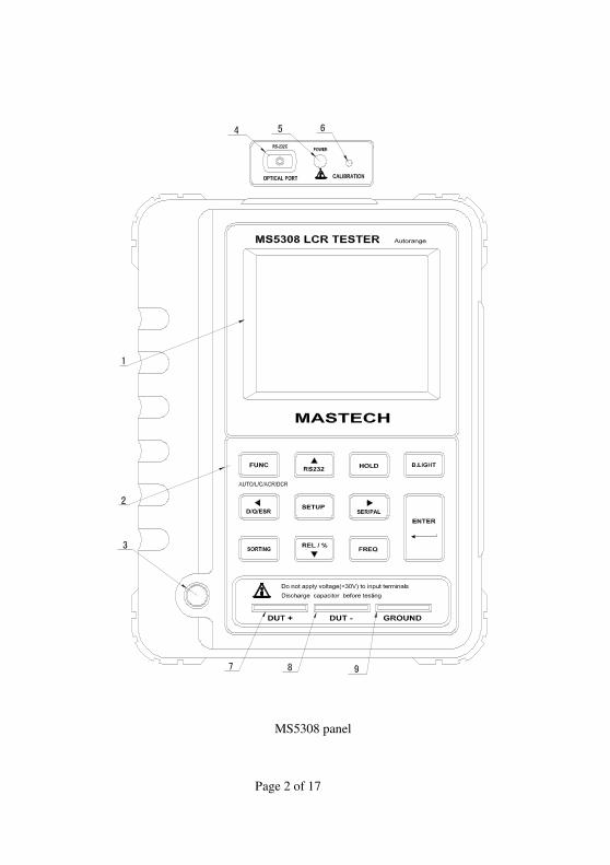
1.1.... Panel description
1 Display
2 Functional buttons area
3 Power switch
4 IR Port
5 External power port
6 Calibration button port
7 DUT + jack
8 DUT - jack
9 Shielding grounding jack
1.2....Inspection
When you get a new LCR meter, please check the instrument and
its accessories. If something is damaged or missed, please contact
the store you bought the instrument from for adjustment or
replacement.
1.3 Accessories
MS5308 LCR digital bridge meter Kelvin test clip (one pair)
SMD test probe IR data line
Upper computer program CD External power supply
Page 2 of 17
MS5308 panel

Page 3 of 17
2. Safety instructions:
Operating environment and condition:
Elevation <2000 m
Relative humidity (RH) ≦ 80%RH
Operating temperature 0 – 40°C
Note: DO NOT input voltage at the measurement port. When
measuring capacitance, please discharge first then measure,
otherwise, the meter will be damaged.
Storage and maintenance: Do not use alcohol or other solvents
to clean the meter. If it will not be used for long time, please
remove battery and put the meter in a dry and clean
environment.
3. Description:
3.1 Definition Description
APO: Auto power off
LCR: This character showing on the LCD means that the tester
works in automatic identification mode
LP: Inductance parallel connection measurement mode
Ls: Inductance series connection measurement mode
CP: Capacitance parallel connection measurement mode
Cs: Capacitance series connection measurement mode
RP: Resistance parallel connection measurement mode
Rs: Resistance series connection measurement mode
DCR: Resistance DC measurement mode
D: Wastage factor
Q: Quality factor
θ: Phase angle value
ESR: Equivalent resistance
DUT: Object for measuring
3.1 Impedance parameter description (see Figure Ⅰ)
Z= Rs+jXs ∠=|Z| θ Rs-=|Z|Cosθ Xs= |Z|Sinθ
Xs /Rs=Tanθ θ=Tan-1 (Xs /Rs)
If θ > 0, it means that the measured object is resistant, if θ < 0, it

Page 4 of 17
means that that the measured object is capacitive.
3.2 Series-parallel connection mode description
This meter has series and parallel measurement modes. When the
capacitance value of the measured object is large or inductance
value is small, use the series mode for more accurate results.
When the capacitance value of the measured object is small or
inductance value is large, use the parallel mode for more accurate
results. This meter can select the measurement mode
automatically according to the measured object.
4. Functional characteristics description:
1. 19,999 (main)/1,999 (secondary) dual LCD display
2. LCR measures with automatic identification and automatic
measurement range
3. L\C\R single measurement selection
4. Resistance measurement in DCR mode
5. D/Q/θ/ESR display on the secondary display
6. Series or parallel measurement modes are selectable
7. Comparison function under single measurement
8. Test frequency 100/120/1k/10k/100k is selectable in AC mode
9. The selection feature for measured components with the same
series
10. Battery power display, auto power off if meter is not operated
for 5 minutes.
11. With infrared transmission interface, the meter is secure
(supporting hot plug). With special software, the meter is easily
managed.
12. See table 1-3 for measurement accuracy and scope
Remarks: This accuracy is the measurement standard. In
DUT jack, the meter-specific probe should be used if required.
Measurement with probe may be influenced by external
environment. To avoid inaccurate measurements, please keep
away from strong magnetic sources.

Page 5 of 17
Table 1 Resistance measurement scope
Note: This accuracy is the measurement standard when D
<0.1, if D> 0.1, it should be multiplied by the extraction
of a root of 1 + D2
Measurem Measurement Measureme Resolutio Accuracy
RS/RP
100Hz/120 200.00Ω 0.01Ω 1.0%+5d
100Hz/120 2.0000KΩ 0.1Ω 0.3%+5d
100Hz/120 20.000KΩ 1Ω 0.3%+5d
100Hz/120 200.00KΩ 0.01kΩ 0.5%+5d
100Hz/120 2.0000MΩ 0.1kΩ 1.0%+5d
100Hz/120 20.000MΩ 1kΩ 1.0%+5d
100Hz/120 200.00MΩ 0.1MΩ 2.0%+5d
1kHz 20.000Ω 0.001Ω 1.0%+5d
1kHz 200.00Ω 0.01Ω 0.3%+5d
1kHz 2.0000KΩ 0.1Ω 0.3%+5d
1kHz 20.000KΩ 1Ω 0.3%+5d
1kHz 200.00KΩ 0.01kΩ 0.5%+5d
1kHz 2.0000MΩ 0.1kΩ 1.0%+5d
1kHz 20.000MΩ 1kΩ 2.0%+5d
1kHz 200.0MΩ 0.1MΩ 5.0%+5d
10kHz 20.000Ω 0.001Ω 1.0%+5d
10kHz 200.00Ω 0.01Ω 0.5%+5d
10kHz 2.0000KΩ 0.1Ω 0.3%+5d
10kHz 20.000KΩ 1Ω 0.5%+5d
10kHz 200.00KΩ 0.01kΩ 1.0%+5d
100kHz 20.000Ω 0.001Ω 1.0%+5d
100kHz 200.00Ω 0.01Ω 1.0%+5d
100kHz 2.0000KΩ 0.1Ω 1.0%+5d
100kHz 20.000KΩ 1Ω 2.0%+5d

Page 6 of 17
Table 2 Capacitance measurement scope
Note: This accuracy is the measurement standard. When D
<0.1, if D> 0.1, it should be multiplied by the extraction of a
root of 1 + D2
Measurem Measurement Measure Resoluti Accuracy
CS/CP
100Hz/120 20.000nF 1pF 1.0%+5d
100Hz/120 200.00nF 0.01nF 0.5%+5d
100Hz/120 2000.0nF 0.1nF 0.5%+5d
100Hz/120 20.000uF 1nF 0.5%+5d
100Hz/120 200.00uF 0.01uF 1.0%+5d
100Hz/120 2000.0uF 0.1uF 2.0%+5d
100Hz/120 20.00mF 0.1mF 2.0%+5d
1kHz 2000.0pF 0.1pF 1.0%+5d
1kHz 20.000nF 1pF 1.0%+5d
1kHz 200.00nF 0.01nF 0.5%+5d
1kHz 2000.0nF 0.1nF 0.5%+5d
1kHz 20.000uF 1nF 0.5%+5d
1kHz 200.00uF 0.01uF 1.0%+5d
1kHz 2000.0uF 0.1uF 1.0%+5d
10kHz 200.00 0.01pF 1.0%+5d
10kHz 2000.0pF 0.1pF 1.0%+5d
10kHz 20.000nF 1pF 1.0%+5d
10kHz 200.00nF 0.01nF 1.5%+5d
10kHz 2000.0nF 0.1nF 2.0%+5d
100kHz 200.00 0.01pF 2.0%+5d
100kHz 2000.0pF 0.1pF 1.0%+5d
100kHz 20.000nF 1pF 2.0%+5d
100kHz 200.00nF 0.01nF 5.0%+5d

Page 7 of 17
Table 3. Inductance measurement scope
Note: This accuracy is the measurement standard. When D
<0.1, if D> 0.1, it should be multiplied by the extraction
Measurem Measurement Measureme Resoluti Accuracy
LS/LP
100Hz/120 20.000mH 1uH 1.0%+5d
100Hz/120 200.00mH 0.01mH 0.5%+5d
100Hz/120 2000.0mH 0.1mH 0.5%+5d
100Hz/120 20.000H 1mH 0.5%+5d
100Hz/120 200.00H 0.01H 1.0%+5d
100Hz/120 2000.0H 0.1H 1.0%+5d
100Hz/120 20.000kH 1H 2.0%+5d
1kHz 2000.0uH 0.1uH 1.0%+5d
1kHz 20.000mH 1uH 0.5%+5d
1kHz 200.00mH 0.01mH 0.5%+5d
1kHz 2000.0mH 0.1mH 1.0%+5d
1kHz 20.000H 1mH 1.0%+5d
1kHz 200.00H 0.01H 2.0%+5d
1kHz 2000.0H 0.1H 5.0%+5d
10kHz 200.00 uH 0.01uH 1.0%+5d
10kHz 2000.0uH 0.1uH 0.5%+5d
10kHz 20.000mH 1uH 0.5%+5d
10kHz 200.00mH 0.01mH 1.5%+5d
10kHz 2000.0mH 0.1mH 2.0%+5d
10kHz 20.000H 0.001H 5.0%+5d
100kHz 20.000 uH 0.001uH 1.0%+5d
100kHz 200.00 uH 0.01uH 2.0%+5d
100kHz 2000.0uH 0.1uH 2.0%+5d
100kHz 20.000mH 1uH 2.0%+5d
100kHz 200.00mH 0.01mH 5.0%+5d
Page 8 of 17
of a root of 1 + D2
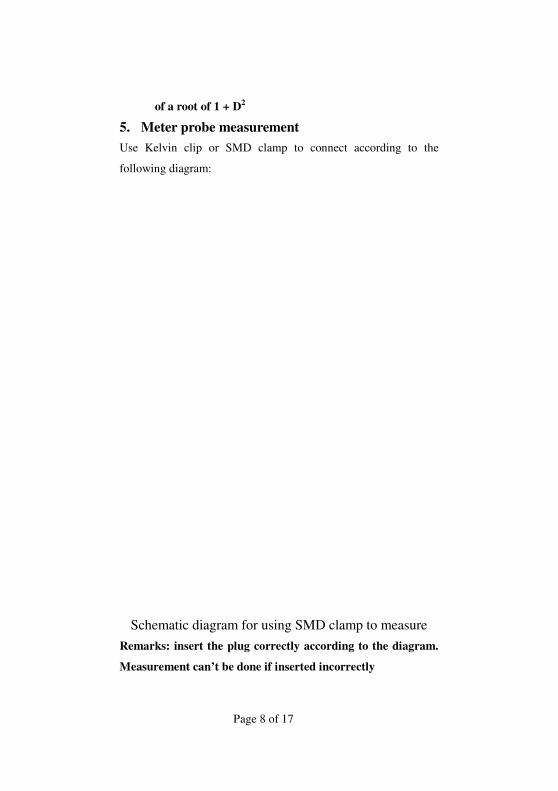
5. Meter probe measurement
Use Kelvin clip or SMD clamp to connect according to the
following diagram:
Schematic diagram for using SMD clamp to measure
Remarks: insert the plug correctly according to the diagram.
Measurement can’t be done if inserted incorrectly

Page 9 of 17
Schematic diagram for using Kelvin clip to measure
Remarks: insert the plug correctly according to the diagram.
Measurement can’t be done if inserted incorrectly.
Page 10 of 17
6 Measurement operation description:
6.1. Automatic measurement:
When the instrument is turned on, the instrument will enter
automatic identification mode by default. At this time, insert the
object to be measured to the measurement side. The instrument
will automatically recognize that the object to be measured is
capacitive resistance or inductor and display the measurement
value in the main display, and display a corresponding
D/Q/θ/value in the secondary display. In this mode, you can
change measurement frequency by operating Frequency.
6.2. Single measurement
When the instrument is turned on, the instrument will enter
automatic identification mode by default. At this time, you can
select L, C, R, DCR and other single measurement modes by
operating Function button. Read the measurement value on the
LCD display after inserting the object to be measured and
selecting the proper mode. In L, C, R mode, you can change the
measurement frequency by operating Frequency button, and you
also can operate Series/Parallel buttons to select parallel
connection measurement or series connection measurement.
6.3. Comparison and selection
When the instrument is turned on, the instrument will be switched
to single measurement mode for the objects to be selected.
Connect the sample objects to be selected at measurement port. At
this time, you can operate Comparison button to enter
comparison and selection mode. PASS or FAIL, will display on
the main display and the measurement value of current object will
display on the secondary display. In this state, press Setup button
Page 11 of 17
to select parameters, and the sample value and error will display
on the LCD. You can modify sample value and error by operating
direction arrows. Select the modification item by operating Ok
button, and confirm the settings. Press Comparison button again
to quit selection mode.
6.4. Deviation proportion measurement
When the instrument is turned on, the instrument will switch to
single measurement mode for the objects to be tested. Insert
reference object in measurement port, press Relevant
Measurement button to save the current vale (DCUR) as reference
value (DREF). At this time, REL will display on the LCD. Insert
the object for measuring in the measurement port and press
Relevant Measurement button again. At this time, REL will
flash on the LCD the reference value will display on the main
display, and the deviation proportion REL% will display on the
secondary display, REL%=(DCUR-DREF)/DREF*100%. When DCUR
is more than two times of DREF, OL% will display on the
secondary display. Press Relevant Measurement button for more
than 2 seconds to quit the measurement state.
6.5 Data Hold function: press Hold button to stop reading
measurement value and show the current measurement value on
the main display continuously. At this time, only Communication
and Backlight keys are available. Press the Hold key again to
return normal measurement mode.
7. Additional functions
7.1 Auto power off function: To prolong battery life, when the
external power supply is not used, APO will display on the LCD,
which means that auto power off is available. The instrument will
automatically power off without any operation for 5 minutes.
Page 12 of 17
7.2 Backlight function: backlight will be enabled when you press
Backlight button. Press Backlight button again to turn off the
backlight. The backlight will turn off automatically after it is on
for 60 seconds.
7.3 Battery power detection function: The meter has a battery
power detection function. Battery power includes four levels and
displays on the LCD screen. When displays for battery,
please replace battery. This meter uses 8 × 1.5V SIZEAA battery.
Batteries with the same model should be used for battery
replacement. Please remember that you can’t use the meter until
the rear cover is tightened.
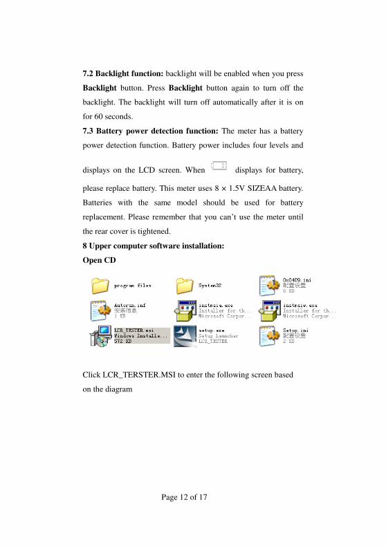
8 Upper computer software installation:
Open CD
Click LCR_TERSTER.MSI to enter the following screen based
on the diagram
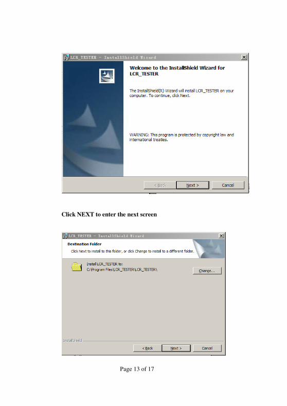
Page 13 of 17
Click NEXT to enter the next screen

Page 14 of 17
Click change to select the position to be changed
Click OK to enter the next screen based on the diagram
Click NEXT
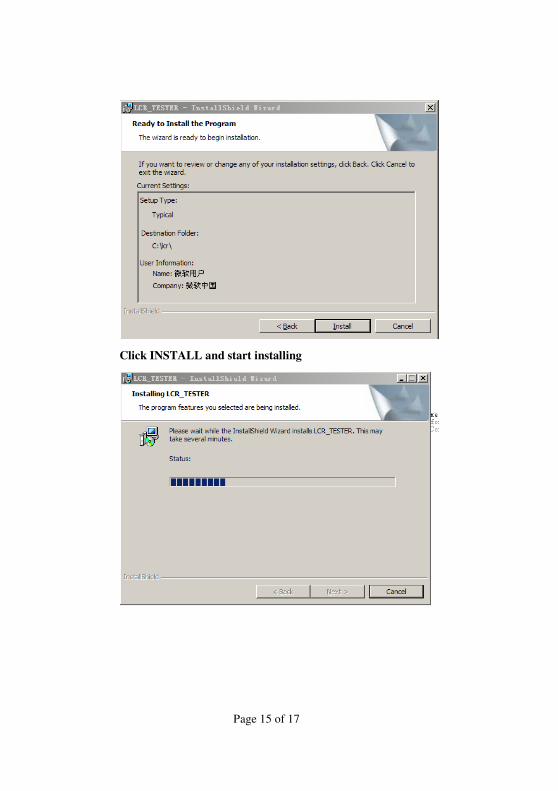
Page 15 of 17
Click INSTALL and start installing
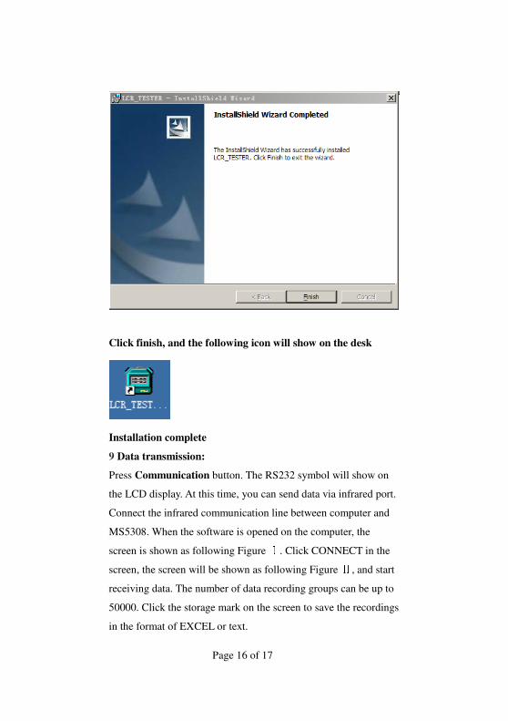
Page 16 of 17
Click finish, and the following icon will show on the desk
Installation complete
9 Data transmission:
Press Communication button. The RS232 symbol will show on
the LCD display. At this time, you can send data via infrared port.
Connect the infrared communication line between computer and
MS5308. When the software is opened on the computer, the
screen is shown as following Figure . Click CONNECT in the Ⅰscreen, the screen will be shown as following Figure , and start Ⅱreceiving data. The number of data recording groups can be up to
50000. Click the storage mark on the screen to save the recordings
in the format of EXCEL or text.

Page 17 of 17
Screen Ⅰ
Screen Ⅱ