Embed Size (px)
Citation preview
General Information Safety precautions…………………………………………….. 2 Packaging………………………………………………………. 2 Disposal………………………………………………………… 2
The Training Apparatus Equipment………………………………………………………. 3 Parts List………………………………………………………… 4 Parts List………………………………………………………… 5 Hardware………………………………………………………… 6
Assembly 1. Assembly instructions………………………………………. 7 2. Mounting the front foot………………………………………. 8 3. Mounting the back foot………………………………………. 8 4. Mounting the pedal…………………………………………… 9 5. Mounting the support cover…………………………………. 9 6. Mounting the saddle…………………………………………. 10 7. Mounting the handbar post………………………………….. 11 8. Mounting the tension control………………………………... 12 9. Mounting the handlebar post………………………………... 12 10. Mounting the computer…………………………………….. 12
The Computer 1. LCD display and computer functions………………………. 13 Using computer………………………………………….………. 13
Training Information Information………………………………………………….……. 14
Other Useful Information Parts list…………………………………………………….…….. 15 Guarantee……………………..…………………………….……. 16
1
General Information SAFETY PRECAUTIONS The training device is intended for use at home. The device fulfils the requirements DIN EN 957-1/5 class HC and has been examined by the TüV-GS (safety standards authority). The device has been tested to this norm with a constant load of a body weight of 150 kg. The CE mark relates to the electromagnetic compatibility (EC guideline 89/336/EWG and EN55081-1). If this device is used incorrectly (e.g. excessive training, jerky movements, without warming up before hand, incorrect setting, etc.) damage to health cannot be ruled out! TRAINING DEVICES OF CLASS C ARE NOT SUITABLE FOR THERAPEUTIC PURPOSES! Before beginning training, a general fitness check should be carried out by your doctor and any cardiac, circulatory or orthopedic problems clarified. PACKAGING Environmentally friendly, recyclable materials: ✎ Outer packaging of cardboard ✎ Form parts of foamed, CFC-free polystyrene (PS) ✎ Foils and bag of polyethylene (PE) ✎ Tension bands of polypropylene (PP) DISPOSAL Please undertake environmentally correct disposal!
2
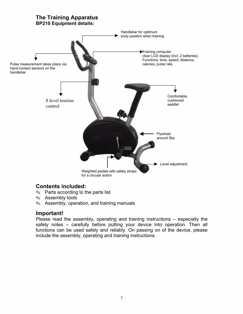
The Training Apparatus BP210 Equipment details:
Handlebar for optimumbody position when training
Training computer clear LCD display (incl. 2 batteries).Functions: time, speed, distance, calories, pulse rate. Pulse measurement takes place via
hand-contact sensors on the handlebar
8 level tension control
Comfortable, cushioned saddle!
Flywheel around 5kg
Level adjustment
Weighted pedals with safety straps for a circular action
Contents included: ✎ Parts according to the parts list ✎ Assembly tools ✎ Assembly, operation, and training manuals
Important! Please read the assembly, operating and training instructions – especially the safety notes – carefully before putting your device into operation. Then all functions can be used safely and reliably. On passing on of the device, please include the assembly, operating and training instructions.
3
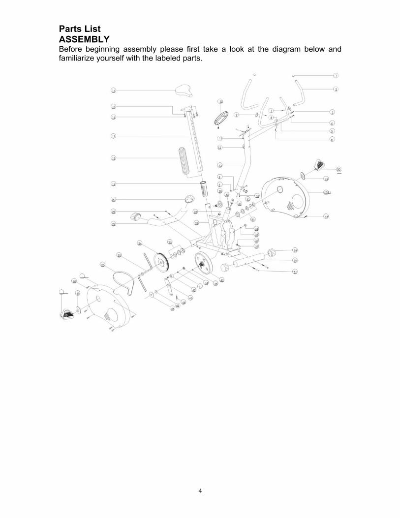
Parts List ASSEMBLY Before beginning assembly please first take a look at the diagram below and familiarize yourself with the labeled parts.
4
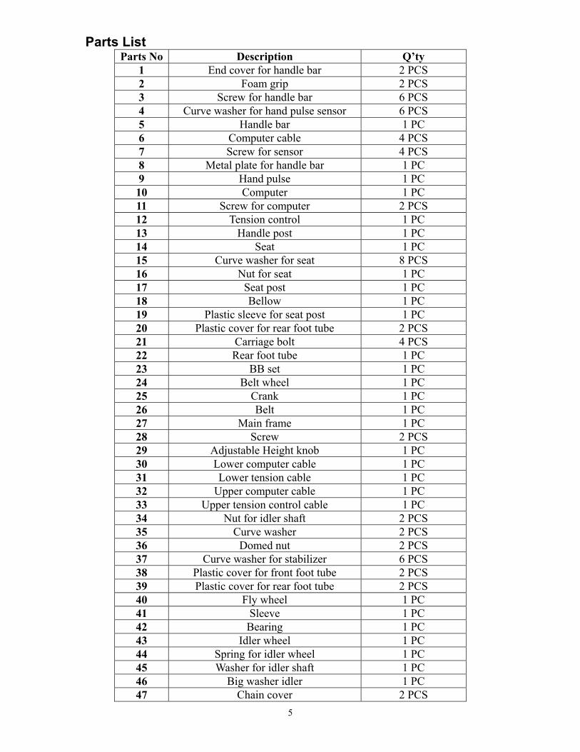
Parts List Parts No Description Q’ty
1 End cover for handle bar 2 PCS 2 Foam grip 2 PCS 3 Screw for handle bar 6 PCS 4 Curve washer for hand pulse sensor 6 PCS 5 Handle bar 1 PC 6 Computer cable 4 PCS 7 Screw for sensor 4 PCS 8 Metal plate for handle bar 1 PC 9 Hand pulse 1 PC 10 Computer 1 PC 11 Screw for computer 2 PCS 12 Tension control 1 PC 13 Handle post 1 PC 14 Seat 1 PC 15 Curve washer for seat 8 PCS 16 Nut for seat 1 PC 17 Seat post 1 PC 18 Bellow 1 PC 19 Plastic sleeve for seat post 1 PC 20 Plastic cover for rear foot tube 2 PCS 21 Carriage bolt 4 PCS 22 Rear foot tube 1 PC 23 BB set 1 PC 24 Belt wheel 1 PC 25 Crank 1 PC 26 Belt 1 PC 27 Main frame 1 PC 28 Screw 2 PCS 29 Adjustable Height knob 1 PC 30 Lower computer cable 1 PC 31 Lower tension cable 1 PC 32 Upper computer cable 1 PC 33 Upper tension control cable 1 PC 34 Nut for idler shaft 2 PCS 35 Curve washer 2 PCS 36 Domed nut 2 PCS 37 Curve washer for stabilizer 6 PCS 38 Plastic cover for front foot tube 2 PCS 39 Plastic cover for rear foot tube 2 PCS 40 Fly wheel 1 PC 41 Sleeve 1 PC 42 Bearing 1 PC 43 Idler wheel 1 PC 44 Spring for idler wheel 1 PC 45 Washer for idler shaft 1 PC 46 Big washer idler 1 PC 47 Chain cover 2 PCS
5
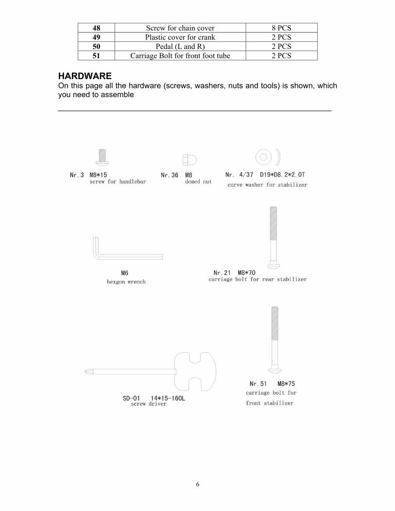
48 Screw for chain cover 8 PCS 49 Plastic cover for crank 2 PCS 50 Pedal (L and R) 2 PCS 51 Carriage Bolt for front foot tube 2 PCS
HARDWARE On this page all the hardware (screws, washers, nuts and tools) is shown, which you need to assemble
6
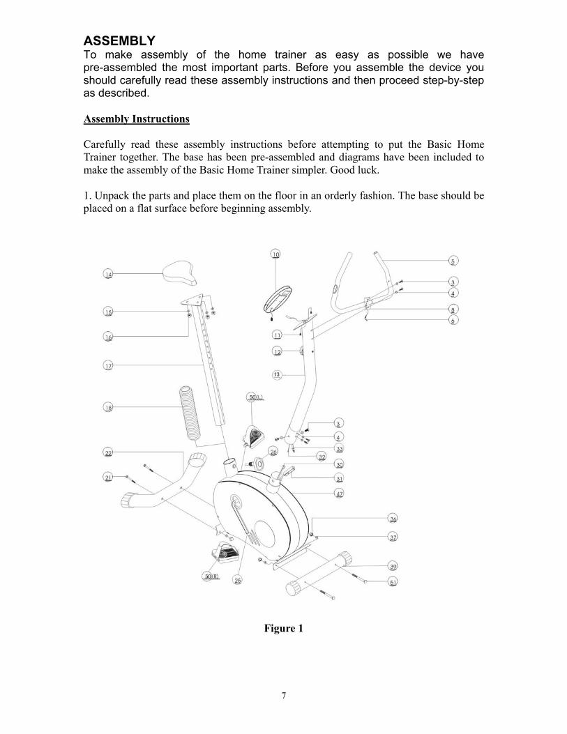
ASSEMBLY To make assembly of the home trainer as easy as possible we have pre-assembled the most important parts. Before you assemble the device you should carefully read these assembly instructions and then proceed step-by-step as described. Assembly Instructions Carefully read these assembly instructions before attempting to put the Basic Home Trainer together. The base has been pre-assembled and diagrams have been included to make the assembly of the Basic Home Trainer simpler. Good luck. 1. Unpack the parts and place them on the floor in an orderly fashion. The base should be placed on a flat surface before beginning assembly.
Figure 1
7
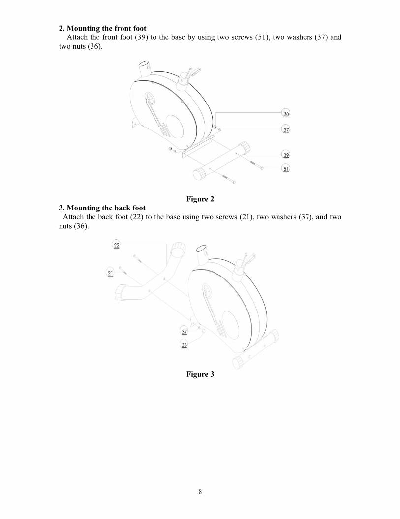
2. Mounting the front foot Attach the front foot (39) to the base by using two screws (51), two washers (37) and
two nuts (36).
Figure 2
3. Mounting the back foot Attach the back foot (22) to the base using two screws (21), two washers (37), and two
nuts (36).
Figure 3
8
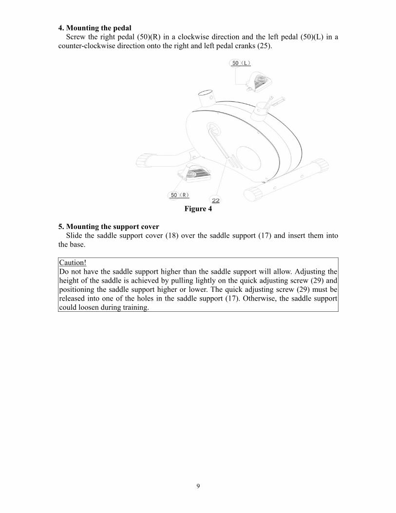
4. Mounting the pedal Screw the right pedal (50)(R) in a clockwise direction and the left pedal (50)(L) in a
counter-clockwise direction onto the right and left pedal cranks (25).
Figure 4
5. Mounting the support cover
Slide the saddle support cover (18) over the saddle support (17) and insert them into the base. Caution! Do not have the saddle support higher than the saddle support will allow. Adjusting the height of the saddle is achieved by pulling lightly on the quick adjusting screw (29) and positioning the saddle support higher or lower. The quick adjusting screw (29) must be released into one of the holes in the saddle support (17). Otherwise, the saddle support could loosen during training.
9
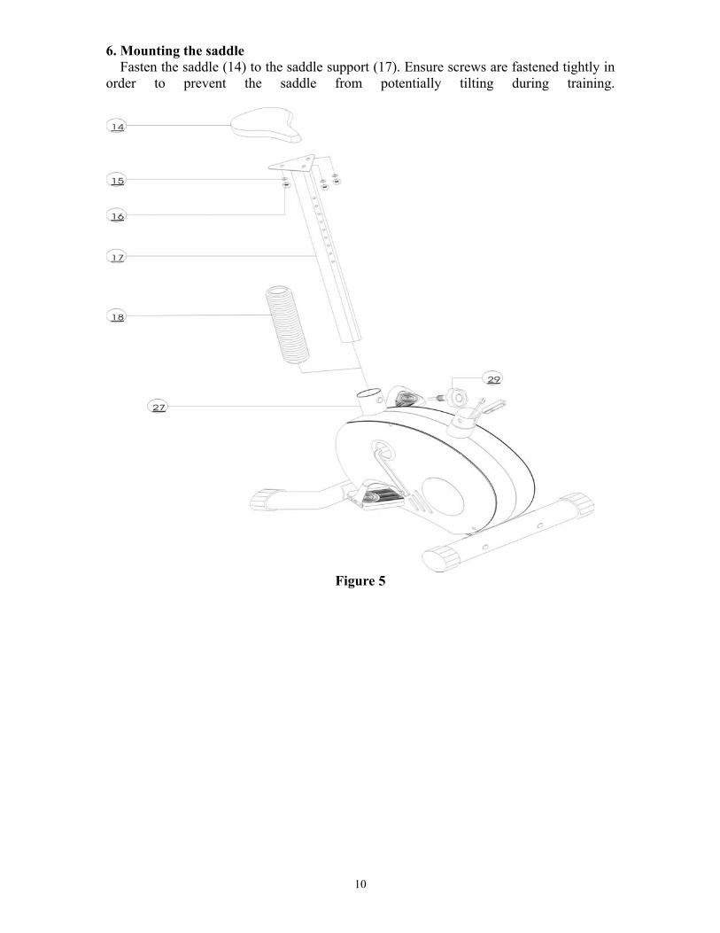
6. Mounting the saddle Fasten the saddle (14) to the saddle support (17). Ensure screws are fastened tightly in
order to prevent the saddle from potentially tilting during training.
Figure 5
10
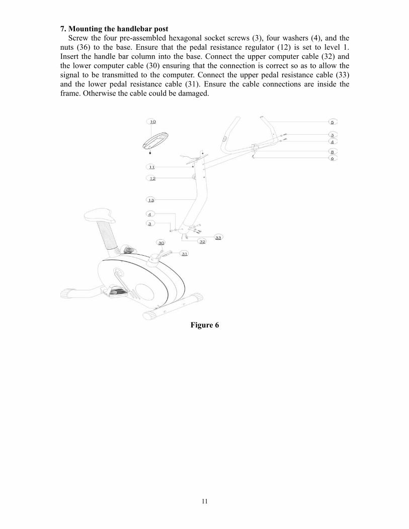
7. Mounting the handlebar post Screw the four pre-assembled hexagonal socket screws (3), four washers (4), and the
nuts (36) to the base. Ensure that the pedal resistance regulator (12) is set to level 1. Insert the handle bar column into the base. Connect the upper computer cable (32) and the lower computer cable (30) ensuring that the connection is correct so as to allow the signal to be transmitted to the computer. Connect the upper pedal resistance cable (33) and the lower pedal resistance cable (31). Ensure the cable connections are inside the frame. Otherwise the cable could be damaged.
Figure 6
11
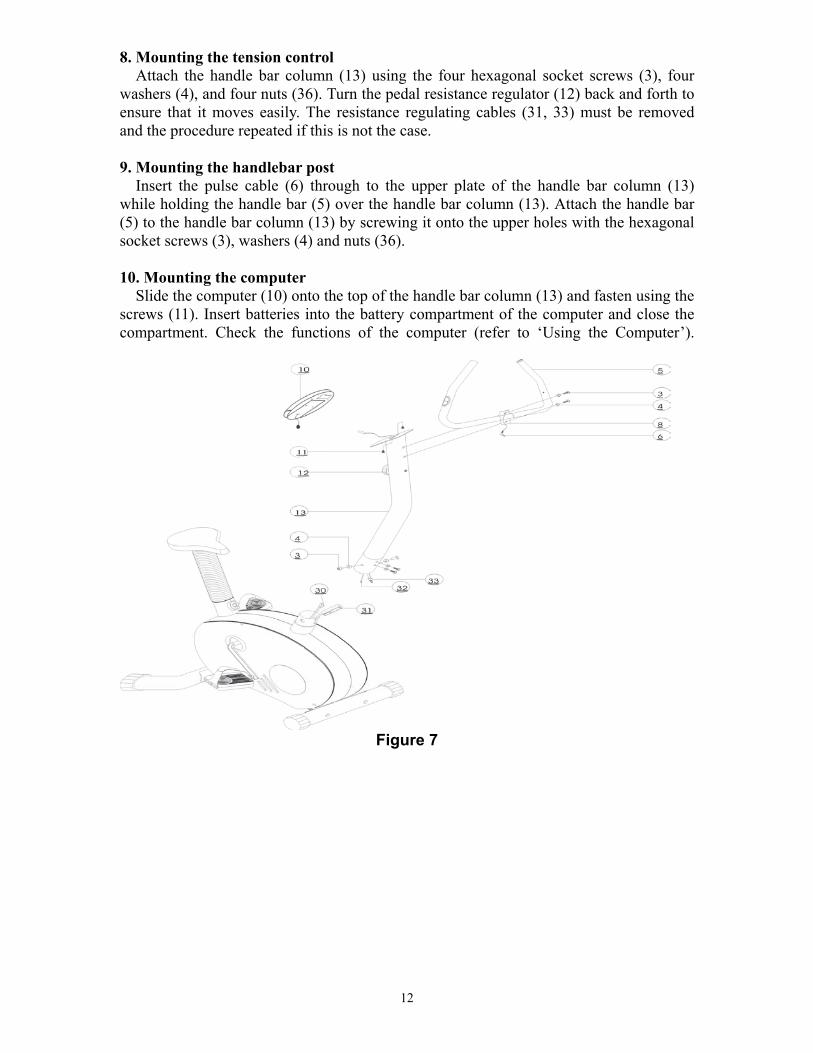
8. Mounting the tension control Attach the handle bar column (13) using the four hexagonal socket screws (3), four
washers (4), and four nuts (36). Turn the pedal resistance regulator (12) back and forth to ensure that it moves easily. The resistance regulating cables (31, 33) must be removed and the procedure repeated if this is not the case. 9. Mounting the handlebar post
Insert the pulse cable (6) through to the upper plate of the handle bar column (13) while holding the handle bar (5) over the handle bar column (13). Attach the handle bar (5) to the handle bar column (13) by screwing it onto the upper holes with the hexagonal socket screws (3), washers (4) and nuts (36). 10. Mounting the computer
Slide the computer (10) onto the top of the handle bar column (13) and fasten using the screws (11). Insert batteries into the battery compartment of the computer and close the compartment. Check the functions of the computer (refer to ‘Using the Computer’).
Figure 7
12
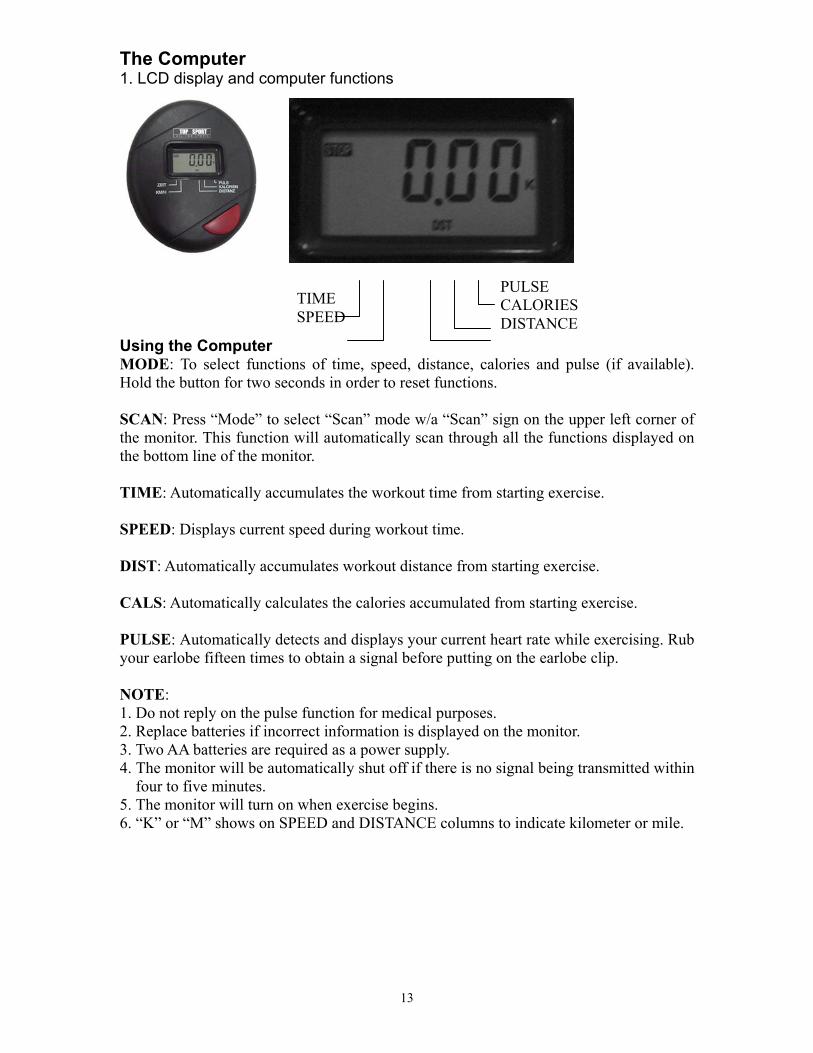
The Computer 1. LCD display and computer functions
Using the Computer MODE: To select functions of time, speed, distance, calories and pulse (if available). Hold the button for two seconds in order to reset functions. SCAN: Press “Mode” to select “Scan” mode w/a “Scan” sign on the upper left corner of the monitor. This function will automatically scan through all the functions displayed on the bottom line of the monitor. TIME: Automatically accumulates the workout time from starting exercise. SPEED: Displays current speed during workout time. DIST: Automatically accumulates workout distance from starting exercise. CALS: Automatically calculates the calories accumulated from starting exercise. PULSE: Automatically detects and displays your current heart rate while exercising. Rub your earlobe fifteen times to obtain a signal before putting on the earlobe clip. NOTE: 1. Do not reply on the pulse function for medical purposes. 2. Replace batteries if incorrect information is displayed on the monitor. 3. Two AA batteries are required as a power supply. 4. The monitor will be automatically shut off if there is no signal being transmitted within
four to five minutes. 5. The monitor will turn on when exercise begins. 6. “K” or “M” shows on SPEED and DISTANCE columns to indicate kilometer or mile.
TIME SPEED
PULSE CALORIES DISTANCE
13
Training Information Information: Generally speaking, any healthy person can start fitness training. Keep in mind, however, that you cannot make up for a long period of neglect in a short time. Physical fitness, increased endurance and well being can easily be achieved through a suitable training program. Your level of fitness will improve after only a relatively short period of regular training and this keeps your heart, circulatory system and locomotors system in shape. Your oxygen absorption capability will also improve. Further positive changes occur within the metabolic system. The important thing is that you tailor your training to your own body and not overdo it. Keep in mind that sports are supposed to be fun. WE STRONGLY RECOMMEND THAT YOU CONSULT YOUR PHYSICIAN BEFORE YOU BEGIN TRAINING.
14
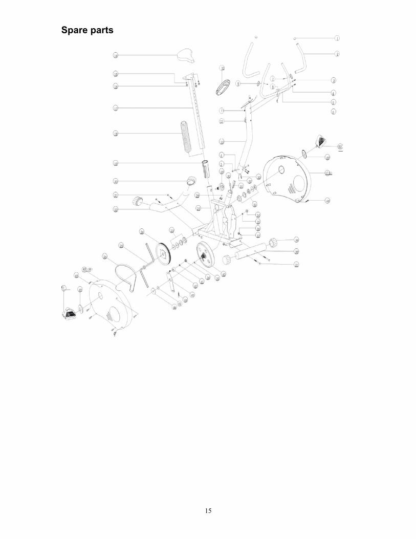
Spare parts
15