Embed Size (px)
Citation preview

GENERAL INFORMATION
SERVICE RULES 1 . Use genuine Honda or Honda-recommended parts and lubricants or their equivalents. Parts that do not meet Honda's
design specifications may cause damage to the scooter. 2. Use the special tools designed for this product to avoid damage and incorrect assembly. 3. Use only metric tools when servicing the scooter. Metric bolts, nuts and screws are not interchangeable with English
fasteners. 4. Install new gaskets, 0-rings, cotter pins, and lock plates when reassembling. 5. When tightening bolts or nuts, begin with the larger diameter or inner bolt first. Then tighten to the specified torque
diagonally in incremental steps unless a particular sequence is specified. 6. Clean parts in cleaning solvent upon disassembly. Lubricate any sliding surfaces before reassembly. ( 7. After reassembly, check all parts for proper installation and operation. 8. Route all electrical wires as shown in the Cable and Harness Routing (page 1 -1 5).
MODEL IDENTIFICATION
)
(
1 -2
GENERAL INFORMATION
SERIAL NUMBERS The Vehicle Identification Number (V.I.N) is stamped on the left side of r--------------------, the frame.
The engine serial number is stamped on the left side of the b.elt case.
The carburetor identification numbers are stamped on the left side of the carburetor body.
VEHICLE IDENTIFICATION NUMBER
1 -3
GENERAL INFORMATION
LABELS The color label is attached as shown. When ordering color-coded parts, ,--------------------, always specify the designated color code.
COLOR LABEL
The safety certification label is attached on the left side of the frame.
SAFETY CERTIFICATION LABEL
The Emission Control Information Label (After '05 model only) is ,------------------, attached on the right side of the frame.
EMISSION CONTROL INFORMATION LABEL
1 -4
GENERAL INFORMATION
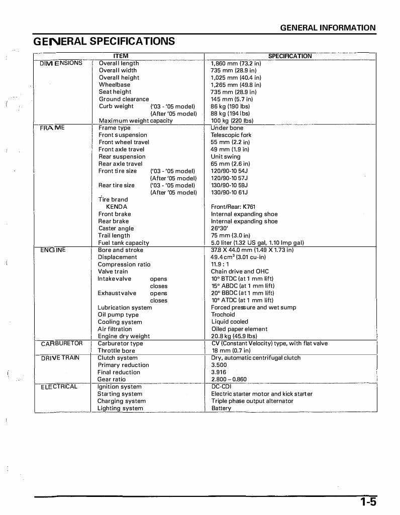
G ENERAL SPECIFICATIONS
ITEM SPECIFICATION DIMENSIONS Overal l length 1 ,860 mm (73.2 in)
Overal l width 735 mm (28.9 in) Overal l height 1 ,025 mm (40.4 in) Wheelbase 1 ,265 mm (49.8 in) Seat height 735 mm (28.9 in) Ground clearance 145 mm (5.7 in) Curb weight ('03 - '05 model) 86 kg (190 lbs)
(After '05 model) 88 kg ( 1941bs) Maximum weight capacity 100 kg (220 lbs)
FRAME Frame type Under bone Front suspension Telescopic fork Front wheel travel 55 mm (2.2 in) Front axle travel 49 mm (1.9 in) Rear suspension Unit swing Rear axle travel 65 mm (2.6 in) Front tire size ('03 - '05 model) 1 20/90-10 5 4J
(After '05 model) 1 20/90-10 57J Rear tire size ('03 - '05 model) 130/90-10 59J
(After '05 model) 130/90-10 61J Tire brand
KENDA Front/Rear: K761 Front brake Internal expanding shoe Rear brake Internal expanding shoe Caster angle 26'30' Trail length 75 mm (3.0 in) Fuel tank capacity 5.0 liter (1.32 US gal, 1.10 Imp gal)
ENGINE Bore and stroke 37.8 X 44.0 mm (1.49 X 1.73 in) Displacement 49.4 em' (3.01 cu-in) Compression ratio 11.9 : 1 Valve train Chain drive and OHC Intake valve opens 10' BTDC (at 1 mm lift)
closes 15' ABDC (at 1 mm lift) Exhau st valve opens 20' BBDC (at 1 mm lift)
closes 10' ATDC (at 1 mm lift) Lubrication system Forced pressure and wet sump Oil pump type Trochoid Cooling system Liquid cooled Air filtration Oiled paper element Engine dry weight 20.8 kg (45.9 lbs)
CARBURETOR Carburetor type CV (Constant Velocity) type, with flat valve Throttle bore 18 mm (0.7 in)
DRI VE TRAIN Clutch system Dry, automatic centrifugal clutch Primary reduction 3.500 Final reduction 3.91 6 Gear ratio 2.800 - 0.860
E LECTRICAL Ignition system DC-CD I Starting system Electric starter motor and kick starter Charging system Triple phase output alternator Lighting system Battery
1 -5
GENERAL INFORMATION
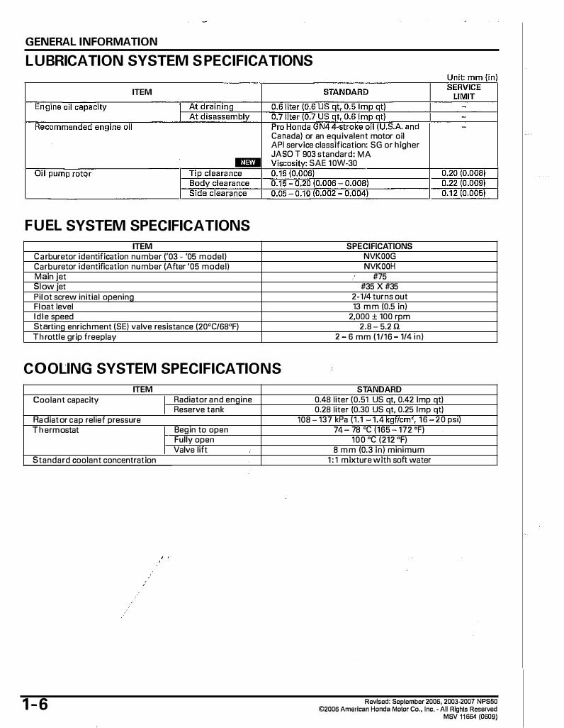
LUBRICATION SYSTEM S PECIFICATIONS
ITEM
Canada) or an equivalent motor oil API service classification: SG or higher JASO T 903 standard: MA
SAE 10W-30
F U EL SYSTEM SPECIFICATIONS
ITEM SPECIFICATIONS Carburetor identification number ('03 - '05 model) NVKOOG Carburetor identification number (After '05 model) NVKOOH Main jet #75 Slow jet #35 X #35 Pilot screw initial opening 2-1/4 turns out Float level 13 mm (0.5 in) Id le speed 2,000 ± 100 rpm Starting enrichment (SE) valve resistance (20'C/68'F) 2.8 5.2!1 Th rottle grip freeplay 2 6 mm (1/16 1/4 in)
COOLING SYSTEM SPECIFICATIONS
ITEM Coolant capacity I Radiator and engine
Reserve tank Radiator cap relief pressure 108 T h ermostat Begin to open
Fully open Valve lift
Standard coolant concentration
1-6
STANDARD 0.48 liter (0.51 US qt, 0.42 Imp qt) 0.28 liter (0.30 US qt, 0.25 Imp qt)
137 kPa (1.1 1.4 kgf/cm<, 16 20 psi) 74 78 'C (165 172 'F)
100 'C (212 'F) 8 mm (0.3 in) minimum
1 : 1 mixture with soft water
Revised: September 2006, 2003·2007 NPS50 ©2006 American Honda Motor Co,, Inc.· All Rights Reserved
MSV 11664 (0609)
GENERAL INFORMATION
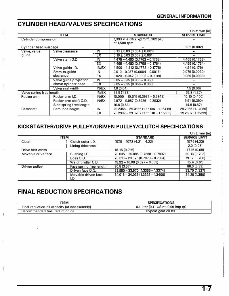
CYLINDER HEAD/VALVES SPECIFICATIONS Unit· mm (in)
ITEM STANDARD SERVICE LIMIT Cylinder compression 1,393 kPa (14.2 kgf/cm', 202 psi) -
at 1,500 rpm Cylinder head warpage - 0.05 (0.002) Valve, valve Valve clearance IN 0.10 ± 0.03 (0.004 ± 0.001) guide EX 0.19 + 0.03 (0.007 + 0.001 ) -
Valve stem O.D. IN 4.475 4.490 (0.1762 0.1768) 4.465 (0.1758) EX 4.465 - 4.480 (0.1758 - 0.1764) 4.455 (0.1 754)
Valve guide I .D. I N/EX 4.500 4.512 (0.1772 0.1776) 4.54 (0.179) Stem-to-guide I N 0.01 0 - 0.037 (0.0004 0.001 5) 0.075 (0.0030) clearance EX 0.020 - 0.047 (0.0008 - 0.0019) 0.085 (0.0033) Valve guide projection IN 9.05 9.35 (0.356 0.368) above cylinder head EX 9.05 - 9.35 (0.356 - 0.368) -Valve seat width IN/EX 1.0 (0.04) 1.5 (0.06)
Valve spring free length I N/EX 33.5 ( 1.32) I 32.2 (1.27) Rocker arm Rocker arm I . D. IN/EX I 10.000 10.015 (0.3937 0.3943) 10.10 (0.400)
Rocker arm shaft 0.0. IN/EX 9.972 - 9.987 (0.3926 - 0.3932) 9.91 (0.390) Side spring free length 16.0 (0.63) 14.5 (0.57)
Camshaft Cam lobe height IN 29.2365 - 29.3165 (1.1 5104 - 1.15419) 29.2065 (1.14986)
I EX 29.2907 29.3707 (1.15318 1.1 5633) 29.2607 (1 .15199)
KICKSTARTER/DRIVE PULLEY /DRIVEN PULLEY /CLUTCH SPECIFICATIONS Unit· mm (in)
ITEM I STANDARD SERVICE LIMIT Clutch Clutch outer I. D. 107.0 - 107.2 (4.21 - 4.22) 107.5 (4.23)
I Lining thickness I 2.0 (0.08) Drive belt width 18.15 (0.715) 17.15 (0.68) Movable drive face Bushing I.D. 20.035 20.085 (0.7888 0.7907) 20.13 (0.793)
Boss O.D. 20.010 - 20.025 (0.7878 - 0.7884) 19.97 (0.786) Weight roller O.D. 15.92 1 6.08 (0.627 0.633) I 15.4 (0.61)
Driven pulley Face spring free length 90.8 (3.57) 86.0 (3.39) Driven face D.O. I 33.950 33.970 (1.3366 1.3374) 33.70 (1.327) Movable driven face 34.01 5 - 34.035 ( 1.3392 - 1.3400) 34.29 (1.350) I. D.
FINAL REDUCTION SPECIFICATIONS
ITEM SPECIFICATIONS Final reduction ail capacity (at disassembly) 0.1 liter (0.11 US qt, 0.09 Imp qt) Recommended final reduction oil Hypaid gear ail #90
1 -7

GENERAL INFORMATION
CRANKSHAFT /PISTON/CYLINDER SPECIFICATIONS Unit· mm (in)
ITEM STANDARD SERVICE LIMIT Crankshaft Connecting rod side clearance 0.1 0 - 0.40 (0.004- 0.016) 0.60 (0.024)
Connecting rod radial clearance 0.004 0.016 (0.0002 0.0006) 0.05 (0.002) Runout - 0.10 (0.004)
Cylinder J.D. 37.800 37.810 (1.4882 1.4886) 37.840 (1.4898) Out-of-round - 0.05 (0.002) Taper 0.05 (0.002) Warpage 0.05 (0.002)
Piston, piston Piston O.D. 37.775 37.795 (1.4872 1.4880) 37.72 (1.485) pin, piston Piston D. D. measurement point 10 mm (0.4 in) from bottom of skirt -rings Piston pin bore I. D. 10.002 10.008 (0.3938 0.3940) 10.04 (0.395)
Piston pin O.D. 9.994- 10.000 (0.3935 0.3937) 9.98 (0.393) Piston-to-piston pin clearance 0.002 0.014 (0.0001 0.0006) 0.04 (0.002) Piston ring-to- Top 0.020 0.050 (0.0008 0.0020) 0.08 (0.003) ring groove clear- Second O.Q15 0.050 (0.0006 0.0020) 0.08 (0.003) a nee Piston ring end Top 0.05 - 0. 1 5 (0.002 0.006) 0.40 (0.016) gap Second 0.05 0.17 (0.002 0.007) 0.40 (0.016)
Oil 0. 1 0 - 0.60 (0.004 0.024) o.80 (0.031 I (side rail)
Cylinder-to-piston clearance 0.005 - 0.035 (0.0002 - 0.0014) 0.08 (0.003) Connecting rod small end J.D. 10.013 10.028 (0.3942 0.3948) 10.05 (0.396) Connecting rod-to-piston pin clearance 0.013 - 0.034 (0.0005 - 0.0013) 0.06 (0.002)
FRONT WHEEL/BRAKE/SUSPENSION/STEERING SPECIFICATIONS Unit" mm (in)
ITEM STANDARD SERVICE LIMIT Minimum tire tread depth 0.8 (0.03) Cold tire pressure 175 kPa (1 .75 kgf/cm', 25 psi) -
Axle runout I 0.20 (0.008) Wheel rim runout Radial - 2.0 (0.08)
Axial 2.0 (0.08) Brake Front brake lever free play 10 - 20 (3/8 - 13/16) -
Drum J.D. 95.0 (3.74) 95.5 (3.76) Lining thickness 3.5 (0.14) 1.0 (0.04)
Fork Spring free length 128.5 (5.06) 125.9 (4.96)
REAR WHEEL/BRAKE/SUSPENSION SPECIFICATIONS Unit· mm (in)
ITEM STANDARD SERVICE LIMIT Minimum tire tread depth 0.8 (0.03) Cold tire pressure 175 kPa (1.75 kgf/cm', 25 psi) -Wheel rim runout Radial 2.0 (0.08)
Axial 2.0 (0.08) Brake Rear brake lever free play 10 20 (3/8 13/16)
Drum J.D. 95.0 (3.74) 95.5 (3.76) Lining thickness 3.5 (0.14) 1.0 (0.04)
1 -8

GENERAL INFORMATION
BATTERY /CHARGING SYSTEM SPECIFICATIONS
ITEM SPECIFICATIONS Battery Capacity 12V 6 Ah
Current leakage 0.1 rnA max. Voltage (20 'C/68 'F) Fully charged 13.0 - 13.2V
Needs charging Below 12.3V Charging current Normal 0.6AI5 - 10h
Quick 3AI1 h Alternator Capacity 190 W/5,000 rpm
Charging coil resistance (20 'C/68 'F) 0.05 o.sn
IGNITION SYSTEM SPECIFICATIONS
ITEM SPECIFICATIONS Spark plug Standard CR8EH-9 (NGK), U24FER9 (DEN SO) ('03 - '05 For cold climate (below 5 'C/41 'F) CR7EH-9 (NGK), U22FER9 (DENSO) model) For extended high speed riding CR9EH-9 (NGI<), U27FER9 (DENSO) Spark plug Standard CR8EH-9 (NGK) (After '05 For cold climate (below 5 'C/41 'F) CR7EH-9 (NGI<) model) For extended high speed riding CR9EH-9 (NGI<) Spark plug gap 0.80 0.90 mm (0.031 0.035 in) Ignition coil peak voltage 80 V minimum Ignition pulse generator peak voltage 0.7 V minimum Ignition timing ("F" mark) 10' BTDC at 2,000 rpm Throttle position I Resistance (20 'C/68 'F) 4 6 kn sensor I Input voltage 4.7 5.3 V
LIGHTS/METERS/SWITCHES SPECIFICATIONS
ITEM Bulbs Headlight (high/low beam)
Brake/tail light Front turn signal light Rear turn signal light Turn signal indicator Speedometer light High beam indicator Water temperature indicator Fuel reserve indicator
Fuse Main fuse Sub fuse
ECT sensor resistance I At 50 'C/122 'F
Fuel pump I At 130 'C /266 'F
I Resistance (20 'C/68 'F) 1 Flow capacity
SPECIFICATIONS 12V-35/35W X 2
12V-27/8W 1 2V-23W X 2 12V-23W X 2
1 2V-3.4W 1 2V-1.7W 1 2V-1.7W
LED LED 20A
10A X 2 690 - 860 Q
68 83 Q 2.6 - 3.2 Q
100 em (3.4 US oz, 3.5 Imp oz) minimum/minute
1 -9
GENERAL INFORMATION
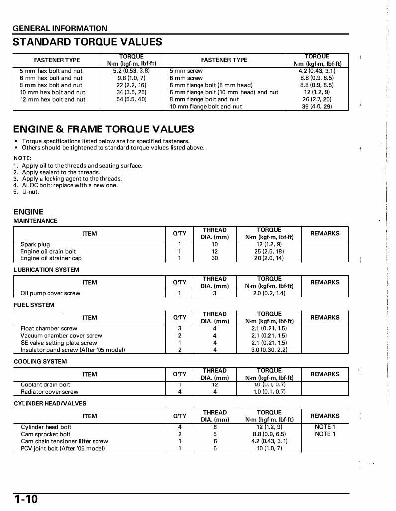
STANDARD TORQUE VALU ES
TORQUE TORQUE FASTENER TYPE
N·m (kgf·m, lbf.ft) FASTENER TYPE
N·m (kgf·m, lbf.ft) 5 mm hex bolt and nut 5.2 (0.53, 3.8) 5 mm screw 6 mm hex bolt and nut 9.8 (1.0, 7) 6 mm screw 8 mm hex bolt and nut 22 (2.2, 16) 6 mm flange bolt (8 m m head) 10 mm hex bolt and nut 34 (3.5, 25) 6 mm flange bolt (10 mm head) and nut 12 mm hex bolt and nut 54 (5.5, 40) 8 mm flange bolt and nut
10 mm flange bolt and nut
ENGINE & FRAME TORQUE VALUES • Torque specifications listed below are for specified fasteners. • Others should be tightened to standard torque values listed above.
NOTE: 1 . Apply oil to the threads and seating surface. 2. Apply sealant to the threads. 3. Apply a locking agent to the threads. 4. ALOC bolt: replace with a new one. 5. U-nut.
ENGINE MAINTENANCE
Spark plug Engine oil drain bolt Engine oil strainer cap
L UBRICATION SYSTEM
Oil pump cover screw
FUEL SYSTEM
Float chamber screw
ITEM
ITEM
ITEM
Vacuum chamber cover screw SE valve setting plate screw Insulator band screw (After '05 model)
COOLING SYSTEM
ITEM
Coolant drain bolt Radiator cover screw
CYLINDER HEAD/VALVES
ITEM
Cylinder head bolt Cam sprocket bolt Cam chain tensioner lifter screw PCV joint bolt (After '05 model)
1 -1 0
Q'TY THREAD
DIA. (mm) 1 10 1 12 1 30
Q'TY THREAD
DIA. (mm) 1 3
Q'TY THREAD
DIA. (mm) 3 4 2 4 1 4 2 4
Q'TY THREAD
DIA. (mm) 1 12 4 4
Q'TY THREAD
DIA. (mm) 4 6 2 5 1 6 1 6
TORQUE N·m (kgf·m, lbf.ft)
12 (1.2, 9) 25 (2.5, 18) 20 (2.0, 14)
TORQUE N·m (kgf·m, lbf.ft)
2.0 (0.2, 1.4)
TORQUE N·m (kgf·m, lbf·ft)
2.1 (0.21, 1.5) 2.1 (0.21 , 1.5) 2.1 (0.21, 1.5) 3.0 (0.30, 2.2)
TORQUE N·m (kgf·m, lbf·ft)
1.0 (0.1, 0.7) 1.0 (0.1 ' 0.7)
TORQUE N·m (kgf·m, lbf·ft)
12 (1.2, 9) 8.8 (0.9, 6.5)
4.2 (0.43, 3.1) 10 (1.0, 7)
4.2 (0.43, 3.1 ) 8.8 (0.9, 6.5) 8.8 (0.9, 6.5)
1 2 (1.2, 9) 26 (2.7, 20) 39 (4.0, 29)
REMARKS
REMARKS
REMARKS
REMARKS
REMARKS
NOTE 1 NOTE 1
GENERAL INFORMATION
KICKSTARTER/DRIVE PULLEY /DRIVEN PULLEY/CLUTCH
ITEM I Q'TV I THREAD I TORQUE REMARKS
DIA. (mm) N·m (kgf·m, lbf·ft) Clutch outer nut I 1 I 10 I 39 (4.0, 29) Drive pulley face nut 1 12 32 (3.3, 24) NOTE 1
FINAL REDUCTION
ITEM Q'TV THREAD I TORQUE I REMARKS DIA. (mm) N·m (kgf·m, lbf·ft)
Final reduction oil check bolt 1 8 I 1 3 (1.3, 9) I ALTERNATOR/STARTER
ITEM Q'TV THREAD TORQUE
REMARKS DIA. (mm) N·m (kgf·m, lbf·ft)
Stator bolt 3 6 12 (1.2, 9) Flywheel nut 1 1 2 44 (4.5, 33) Radiator cooling fan bolt 3 6 7.8 (0.8, 5.8)
CRANKSHAFT /PISTON/CYLINDER
ITEM Q'TV THREAD I TORQUE REMARKS
DIA. (mm) N·m (l<gf·m, lbf·ft) Crankcase bolt 9 6 I 12 (1.2, 9) NOTE 1
LIGHTS/METERS/SWITCHES
ITEM Q'TV THREAD TORQUE REMARKS
DIA. (mm) N·m (kgf·m, lbf·ft) ECT sensor 1 PT 1/8 9.8 (1.0, 7) NOTE 2
Insulator clamp ('03 - '05 model): 5 + 1 mm (0.2 + 0.04 in)
,t='\ � II n� A�
FRAME ENGINE MOUNTING
ITEM Q'TV THREAD TORQUE REMARKS
DIA. (mm) N·m (kgf·m, lbf·ft) Engine hanger link bolt (frame side) 2 10 39 (4.0, 29) Engine mounting nut (engine side) 1 10 49 (5.0, 36) NOTE 5
FRONT WHEEL/BRAKE/SUSPENSION/STEERING
ITEM Q'TV THREAD TORQUE REMARKS
DIA. (mm) N·m (kgf·m, lbf·ft) Front axle nut 1 10 44 (4.5, 33) NOTE 5 Front brake arm nut 1 5 5.4 (0.55, 4.0) Handle post nut 1 1 0 42 (4.3, 3 1 ) NOTE 5 Steering stem lock nut 1 BC1 69 (7.0, 51 )
REAR WHEEL/BRAKE/SUSPENSION
ITEM Q'TV THREAD TORQUE REMARKS
DIA. (mm) N·m (kgf·m, lbf·ft) Rear axle nut 1 14 1 18 (1 2.0, 87) NOTE 1, 5 Rear brake arm bolt 1 5 4.9 (0.5, 3.6) NOTE 4 Rear shock absorber mounting bolt (UPPER) 1 10 38 (3.9, 28)
(LOWER) 1 8 26 (2.7, 20)
1 -1 1

GENERAL INFORMATION
LIGHTS/METERS/SWITCHES
ITEM Q'TY THREAD TORQUE
REMARKS DIA. (mm) N·m (l<gf·m, lbf.ft) Turn signal light mounting nut 4 10 9.8 (1.0, 7)
OTHERS
ITEM Q'TY THREAD TORQUE
REMARKS DIA. (mm) N·m (kgf·m, lbf.ft)
Front/rear frame assembly bolt 4 10 44 (4.5, 33)
1 -1 2
LUBRICATION & SEAL POINTS
ENGINE
LOCATION ECT sensor threads
Crankcase mating surface Transmission case mating surface Kickstarter spindle seating surface Kickstarter driven gear seating surface/friction spring sliding surface Final shaft seating surface (belt case side) Countershaft seating surface Rocker arm sliding and slipper surface Valve stem (valve guide sliding surface) Camshaft cam lobes
D riven face bearing
O i l pump drive, driven gear teeth and sliding sur-face O i l pump driven gear sliding surface of stator base Camshaft bearing Rocker arm shaft sliding surface Cylinder head bolt threads and seating surfaces (6 X 119 mm) P iston pin outer surface P iston and cylinder sliding surfaces P iston ring groove, pin hole of piston Cam sprocket bolt threads and seating surfaces D rive pulley face nut threads and seating surface P iston ring whole surface Each transmission gear teeth Crankcase bolt threads and seating surface Connecting rod big end bearing Connecting rod small end hole Crankshaft main journal bearings Cam chain Oi l seal lips and outer surfaces Cam sprocket gear teeth Each D-ring whole surface
GENERAL INFORMATION
MATERIAL REMARKS Liquid sealant Do not apply sealant to the (Three Bond 12078 or equiv- sensor threads head. alent) See page 13-11
See page 11-11 Molybdenum Apply 0.2 - 0.5g. disulfide paste
Molybdenum Apply 0.3 - 0.5g. disulfide grease Apply 0.5 - 1.0g. Molybdenum disulfide oil (a mixture of 1/2 engine oil and 1/2 molybde-num disulfide grease) Multi-purpose grease
Engine oil
Fill up 3 cc.
Fill up 2 cc per each bearing.
1 -1 3
GENERAL INFORMATION
FRAME
LOCATION MATERIAL REMARKS Front wheel dust seal lips Multi-purpose Speedometer gear teeth grease Front brake panel dust seal lips Brake cams Brake panel anchor pins Fork spring taper area I Apply grease 6.5 - Bg. Fork rebound spring Fork guide bush ing inner surface Fork dust seal lips Fork dust seal-to-snap ring area Fill up 1.5 - 2g. Throttle grip pipe flange cable groove Brake lever pivots Steering stem bearings and race sliding surface Apply 3 - 5g per each bearing. Main stand pivot Front/rear brake cam felt seal Engine oil Rear axle nut threads and seating surface Throttle cable casing inside Cable lubricant Brake cable casing inside Handlebar grip rubber inside H onda bond A or Air cleaner connecting h ose-to-housing mating area equivalent
1 -1 4

CABLE & HARNESS ROUTING
'03 - '05 MODEL:
LEFT HANDLEBAR SWITCH WIRE
FRONT BRAKE CABLE
RIGHT HANDLEBAR SWITCH WIRE
TURN SIGNAL INDICATOR WIRE
SPEEDOMETER CABLE
� C�J FRONT
GENERAL INFORMATION
REAR BRAKE LIGHT SWITCH WIRE
REAR BRAKE CABLE
HANDLEBAR
SPEEDOMETER STAY
A: RIGHT HANDLEBAR SWITCH WIRE B: FRONT BRAKE LIGHT SWITCH WIRE C: THROTTLE CABLE D: FRONT BRAKE CABLE E: REAR BRAKE LIGHT SWITCH WIRE F: LEFT HANDLEBAR SWITCH WIRE G: REAR BRAKE CABLE H: SPEEDOMETER LIGHT WIRE
1 -1 5

GENERAL INFORMATION
AFTER '05 MODEL:
RIGHT H AN DLEBAR SWITCH WIRE
TURN SIGNAL INDICATOR WIRE
REAR BRAKE CABLE
SPEEDOMETER CABLE
1 -1 6
LEFT HANDLEBAR �"IITr·� WIRE
REAR BRAKE LIGHT SWITCH WIRE
REAR BRAKE CABLE
SPEEDOMETER STAY
A: RIGHT HANDLEBAR SWITCH WIRE B: FRONT BRAKE LIGHT SWITCH WIRE C: THROTTLE CABLE D: FRONT BRAKE CABLE E: REAR BRAKE LIGHT SWITCH WIRE F: LEFT HANDLEBAR SWITCH WIRE G: REAR BRAKE CABLE H : SPEEDOMETER LIGHT WIRE
'03 - '05 MODEL:
SPEEDOMETER CABLE
CLAMP (ATWHITE TAPE) WIRE A, B, E, F, H, I, I<
FRONT BRAKE CABLE
FRONT BRAKE CABLE
REAR BRAI<E CABLE
SPEEDOMETER CABLE
GENERAL INFORMATION
GROUND CABLE
STAY
A: RIGHT HAN DLEBAR SWITCH WIRE B: FRONT BRAKE LIGHT SWITCH WIRE C: THROTTLE CABLE D: FRONT BRAKE CABLE E: LEFT HANDLEBAR SWITCH WIRE F: REAR BRAKE LIGHT SWITCH WIRE G: REAR BRAKE CABLE H: SPEEDOMETER LIGHT WIRE
c
1: WATER TEMPERATURE INDICATOR WIRE J: SPEEDOMETER CABLE 1<: TURN SIGNAL I N DICATOR LIGHT WIRE
1 - 1 7
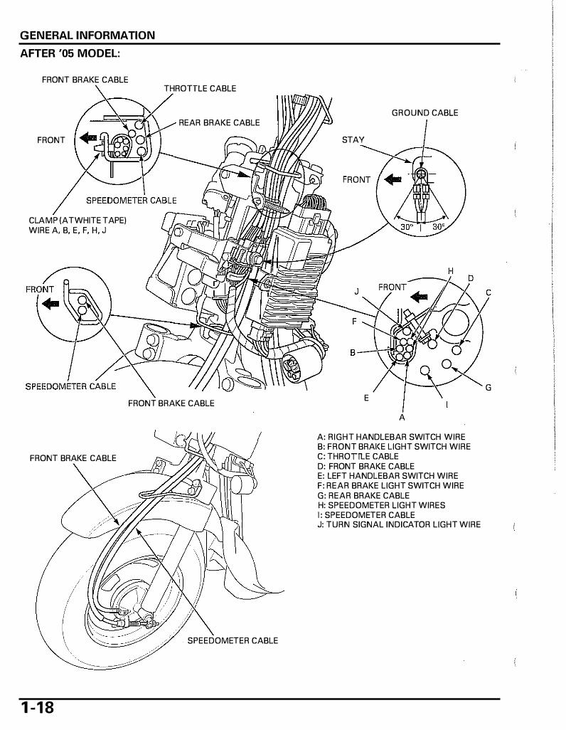
GENERAL INFORMATION
AFTER '05 MODEL:
FRONT BRAKE CABLE
FRONT
CLAMP (ATWHITE TAPE) WIRE A. B, E, F, H, J
FRONT BRAKE CABLE
1 -1 8
THROTTLE CABLE
REAR BRAKE CABLE
FRONT BRAKE CABLE
SPEEDOMETER CABLE
GROUND CABLE
STAY
E
A: RIGHT HANDLEBAR SWITCH WIRE B: FRONT BRAI< E LIGHT SWITCH WIRE C: THROTTLE CABLE D: FRONT BRAKE CABLE E: LEFT HANDLEBAR SWITCH WIRE F: REAR BRAKE LIGHT SWITCH WIRE G: REAR BRAKE CABLE H: SPEEDOMETER LIGHT WIRES 1: SPEEDOMETER CABLE J: TURN SIGNAL INDICATOR LIGHT WIRE
c
G

ENGINE CONTROL (EC;�M��=-, j'�'"'
HORN WIRES
/"\ HEADLIGHT/H ORN TURN SIGNAL LIGHT 6P CONNECTOR WIRE CONNECTORS
GENERAL INFORMATION
RESISTOR
THROTTLE CABLE
FRONT
FRONT
1 - 1 9
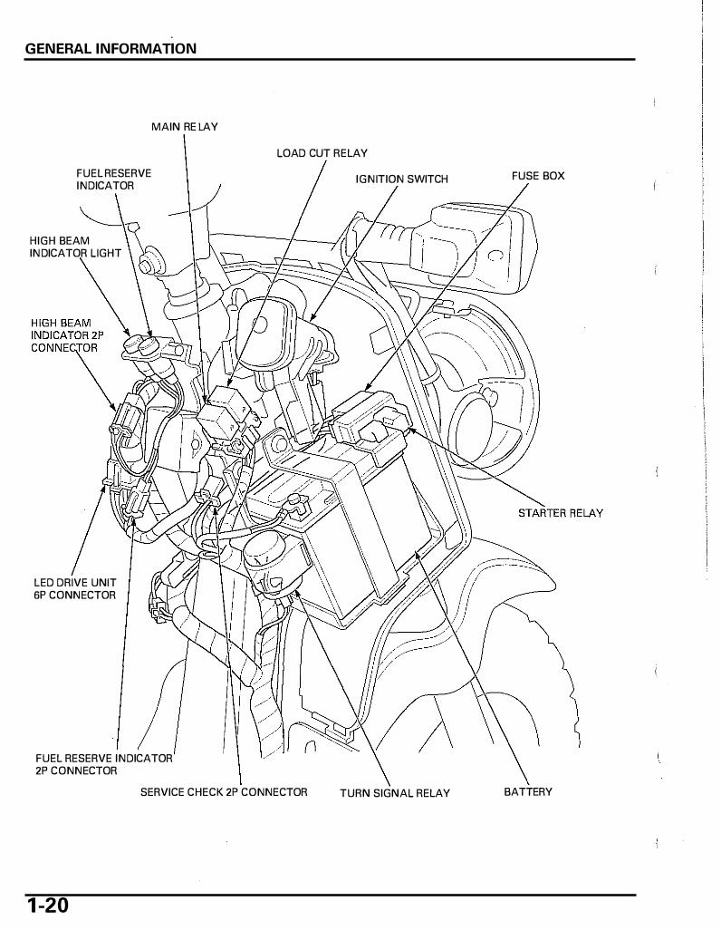
GENERAL INFORMATION
FUEL RESERVE INDICATOR
HIGH BEAM IN DICATOR LIGHT
LED DRIVE UNIT 6P CONNECTOR
MAIN RELAY
FUEL RESERVE INDICATOR 2P CONNECTOR
LOAD CUT RELAY
IGNITION SWITCH
SERVICE CHECK 2P CONNECTOR TURN SIGNAL RELAY
1 -20
FUSE BOX
BATIERY

'03 - '05 MODEL:
FUEL FILTER
THROTTLE CABLE AIR SUPPLY HOSE
AFTER '05 MODEL:
FUEL FILTER
THROTTLE CABLE AIR SUPPLY HOSE
FUEL HOSE
FUEL HOSE
GENERAL INFORMATION
20'
FUEL PUMP WIRE
FU EL FILTER
20'
1 -2 1
GENERAL INFORMATION
'03 - '05 MODEL:
FUEL TANK
REAR BRAI< E CABLE
AFTER '05 MODEL:
FUEL TANK
REAR BRAKE CABLE
1 -22
UNDER COVER
·-·---, 2oJ:'--::rf· =· :jj::__:::,__ AIR SUPPLY HOSE
THROTTLE CABLE
FUEL RESERVE SENSOR 3P CONNECTOR
MAIN WIRE HARNESS
UNDER COVER
AIR SUPPLY HOSE (WITH HOSE PLUG)
FUEL RESERVE SENSOR 3P CONNECTOR
MAIN WIRE HARNESS
GENERAL INFORMATION
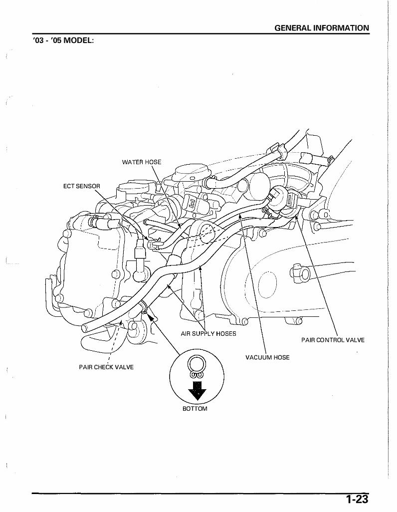
'03 - '05 MODEL:
ECT SEN SOR
PAIR CON TROL VALVE
VACUUM HOSE
PAIR CHECK VALVE
BOTTOM
1 -23
GENERAL INFORMATION
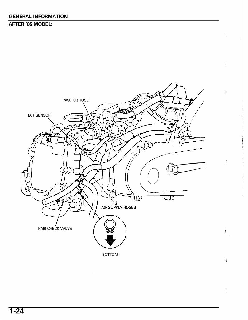
AFTER '05 MODEL:
WATER HOSE
ECT SENSOR
0 w===
PAIR CHECK VALVE
BOTTOM
1 -24
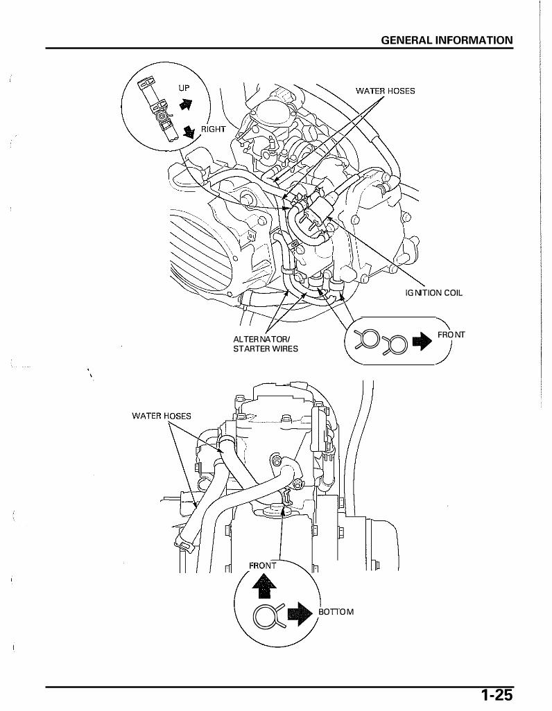
ALTERNATOR/ STARTER WIRES
a+ BOTIO M
GENERAL INFORMATION
IGNITION COIL
JOn+ FRONT
1 -25
GENERAL INFORMATION
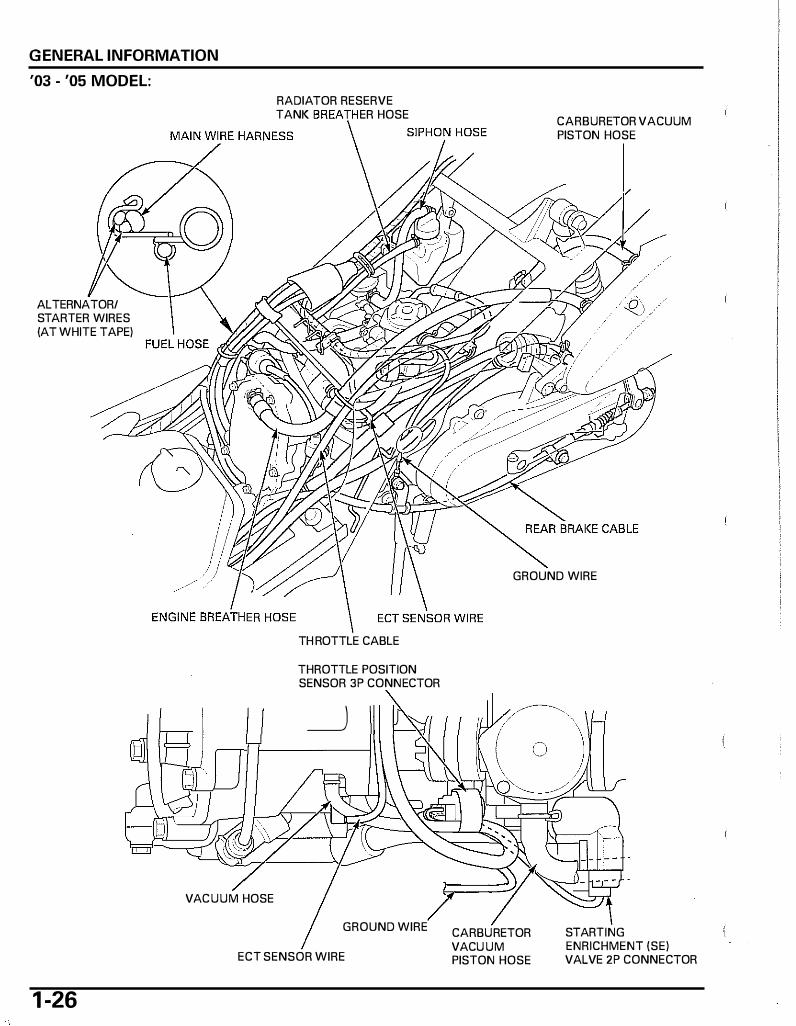
'03 - '05 MODEL:
ALTERNATOR/ STARTER WIRES (AT WHITE TAPE)
VACUUM HOSE
RADIATOR RESERVE TANK ER HOSE
TH ROTTLE CABLE
THROTTLE POSITION SENSOR 3P CONNECTOR
_j
GROUND WIRE
ECT SENSOR WIRE
1 -26
CARBURETOR VACUUM PISTON HOSE
GROUND WIRE
CARBURETOR VACU UM PISTON HOSE
STARTING ENRICHMENT (SE) VALVE 2P CONNECTOR

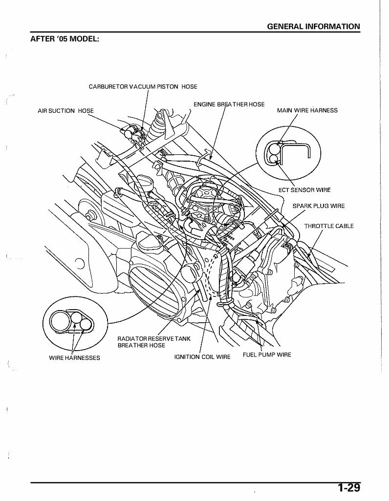
AFTER '05 MODEL:
ALTERNATOR/ STARTER WIRES (AT WHITE TAPE)
RADIATOR RESERVE TAN K BREA HOSE
GENERAL INFORMATION
AIR SUCTION HOSE
MAIN WIRE HARN ESS <::IP�lnN HOSE
GROUND WIRE
EN GINE BREATHER HOSE ECT SENSOR WIRE
THROTTLE CABLE
THROTTLE POSITION SEN SOR 3P CONN ECTOR
__j
ECT SEN SOR WIRE CARBURETOR VACUUM PISTON HOSE
STARTING EN RICHMENT (SE) VALVE 2P CONN ECTOR
1 -27

GENERAL INFORMATION
'03 - '05 MODEL:
CARBURETOR VACUUM PISTON HOSE ENGINE BREATHER H OS E MAIN WIRE HARNESS
WIRE HARNESSES
RADIATOR RESERVE TANK BREATHER HOSE
RADIATOR RESERVE TANK BREATHER HOSE
IGNITION COIL WIRE FUEL PUMP WIRE
RADIATOR RESERVE TANK BREATHER HOSE FUEL HOSE
1 -28
SPARK PLUG WIRE
GENERAL INFORMATION
AFTER '05 MODEL:
CARBURETOR VACUUM PISTON HOSE
AIR SUCTION HOSE
WIRE HARNESSES
RADIATOR RESERVE TAN I< BREATHER HOSE
ENGINE BR ATHER HOSE MAIN WIRE HARNESS
IGNITION COIL WIRE FUEL PUMP WIRE
1 -29
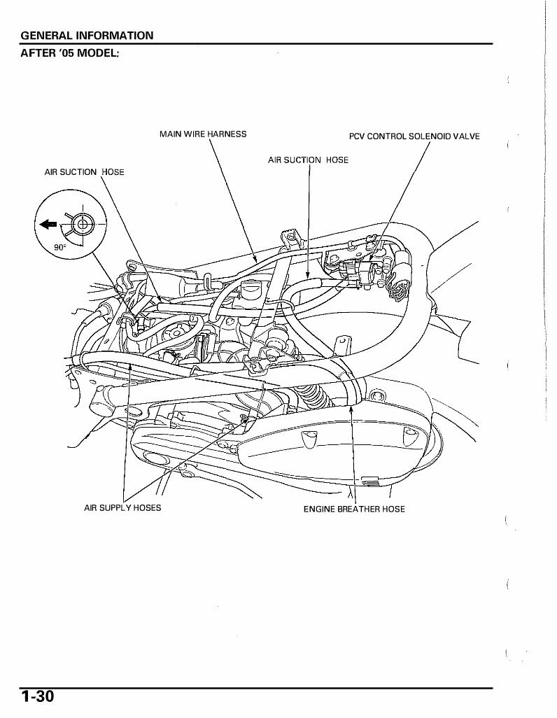
GENERAL INFORMATION
AFTER '05 MODEL:
AIR SUCTION
MAIN WIRE HARNESS PCV CONTROL SOLENOID VALVE
AIR SUPPLY H OSES ENGINE BREATH ER H OSE
1 -30

'03 - '05 MODEL:
8
AFTER '05 MODEL:
AIR SUCTION H OSES
GENERAL INFORMATION
A: RIGHT TURN SIGNAL LIGHT WIRES
8: LEFT TURN SIGNAL LIGHT WIRES
TAIL LIGHT WIRES
A
A 8
A
A: RIGHT TURN SIGNAL LIGHT WIRES
8: LEFT TURN SIGNAL LIGHT WIRES
TAIL LIGHT WIRES
A
8
1 -3 1

GENERAL INFORMATION
REAR BRAKE CABLE
1 -32
ENGINE BREATHER DRAIN H OSE
··'/
'\=: IC
!LJC /�
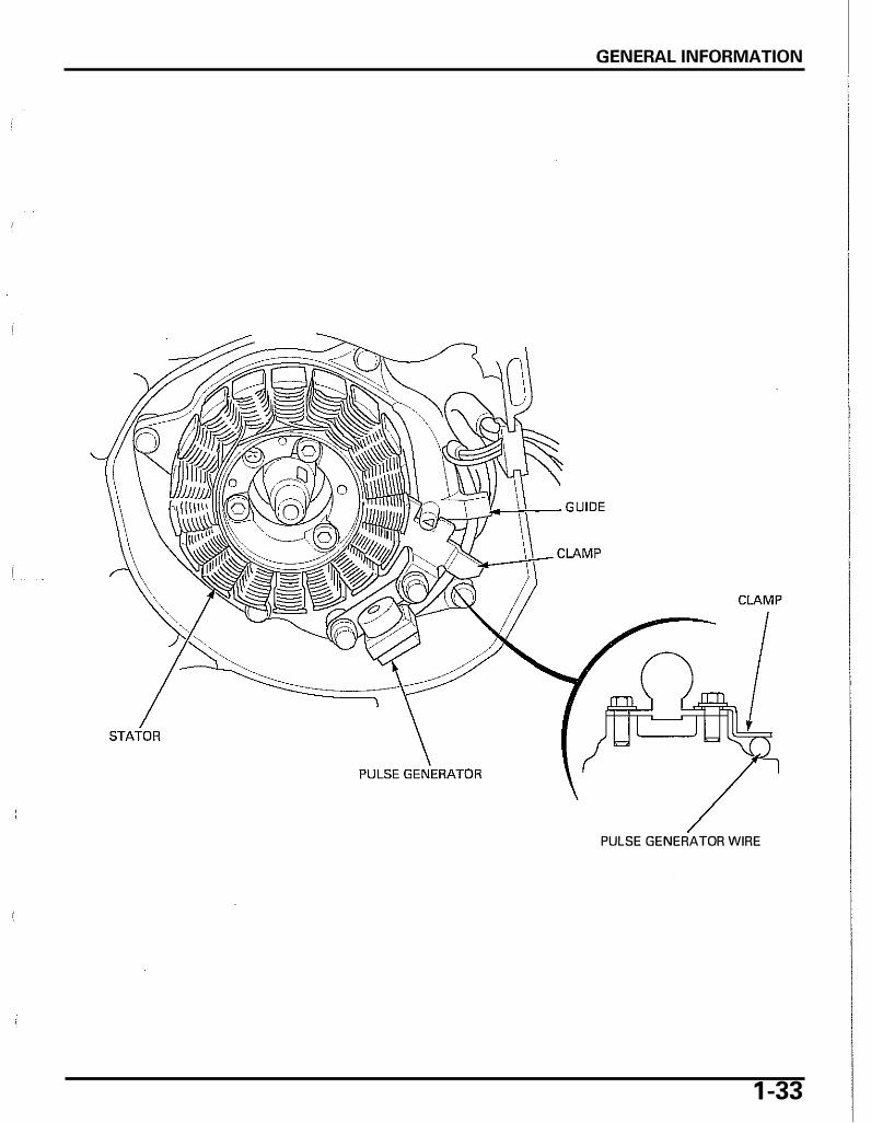
GENERAL INFORMATION
PULSE GENERATOR WIRE
1 -33
GENERAL INFORMATION
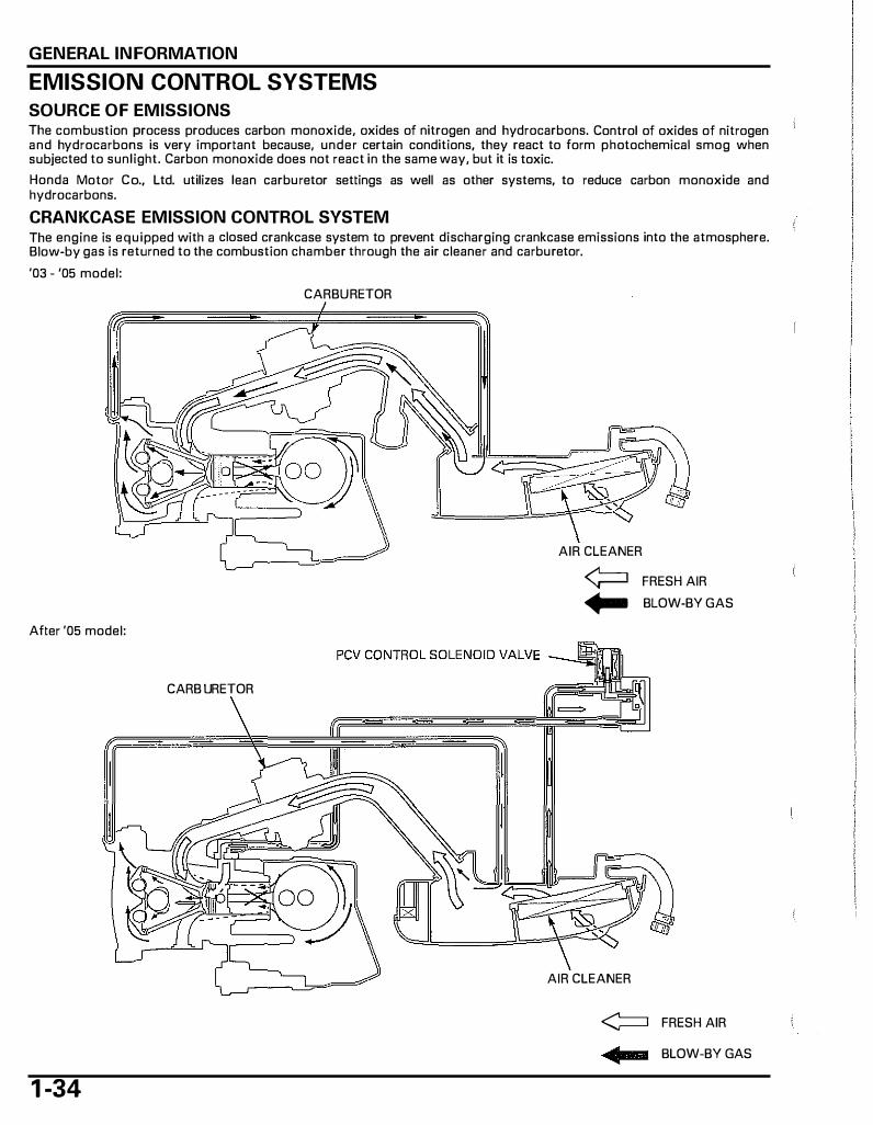
EMISSION CONTROL SYSTEMS
SOURCE OF EMISSIONS Th e combustion process produces carbon monoxide, oxides of nitrogen and hydrocarbons. Control of oxides of nitrogen and hydrocarbons is very important because, under certain conditions, th ey react to form photochemical smog when subjected to sunlight. Carbon monoxide does not react in th e same way, but it is toxic.
Honda Motor Co., Ltd. utilizes lean carburetor settings as well as other systems, to reduce carbon monoxide and hydrocarbons.
CRANKCASE EMISSION CONTROL SYSTEM Th e engine is equipped with a closed crankcase system to prevent discharging crankcase emissions into th e atmosphere. Blow-by gas is returned to th e combustion chamber through th e air cleaner and carburetor.
'03 - '05 model:
CARBURETOR
After '05 model:
CARBURETOR
1 -34
AIR CLEANER
¢::1 FRESH AIR ... BLOW-BY GAS
AIR CLEANER
<::= FRESH AIR
• BLOW-BY GAS
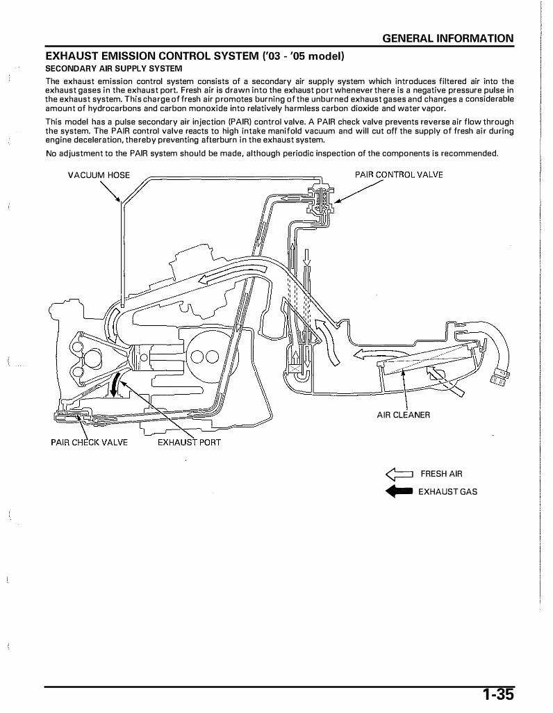
EXHAUST EMISSION CONTROL SYSTEM ('03 - '05 model) SECONDARY AIR SUPPLY SYSTEM
GENERAL INFORMATION
The exhaust emission control system consists of a secondary air supply system which introduces filtered air into the exhaust gases in the exhaust port. Fresh air is drawn into the exhaust port whenever there is a negative pressure pulse in the exhaust system. This charge of fresh air promotes burning of the unburned exhaust gases and changes a considerable amount of hydrocarbons and carbon monoxide into relatively harmless carbon dioxide and water vapor.
This model has a pulse secondary air injection (PAIR) control valve. A PAIR check valve prevents reverse air flow through the system. The PAIR control valve reacts to high intake manifold vacuum and will cut off the supply of fresh air during engine deceleration, thereby preventing afterburn in the exhaust system.
No adjustment to the PAIR system should be made, although periodic inspection of the components is recommended.
VACUUM HOSE �
AIR CLEANER
¢=::1 FRESH AIR
... EXHAUST GAS
1 -35

GENERAL INFORMATION
EXHAUST EMISSION CONTROL SYSTEM (After '05 model) SECONDARY AIR SUPPLY SYSTEM
The secondary air supply system introduces filtered air into the exhaust gases in the exhaust port. Fresh air is drawn into the exhaust port whenever there is a negative pressure pulse in the exhaust system. This charge of fresh air promotes burning of the unburned exhaust gases and changes a considerable amount of hydrocarbons and carbon monoxide into relatively harmless carbon dioxide and water vapor.
No adjustment to the PAIR system should be made, although periodic inspection of the components is recommended.
AIR CLEAN ER
PAIR CHECK VALVE <;=:::J FRESH AIR
EXHAUST PORT • EXHAUST GAS
OXIDATION CATALYTIC CONVERTER
This scooter is equipped with an oxidation catalytic converter.
This oxidation catalytic converter is in the exhaust system. Through chemical reactions, it converts H C and CO in the engine's exhaust to carbon dioxide (COz ) and water vapor.
NOISE EMISSION CONTROL SYSTEM TAMPERING WITH THE N OISE CONTROL SYSTEM IS PROHIBITED: U.S. Federal law prohibits, or Canadian provincial law may prohibit the fallowing acts or the causing thereof: ( 1 ) The removal or rendering inoperative by any person, ather tan far purposes of maintenance, repair or replacement, of any device or element of design incorporated into any vehicle far the purpose of noise control prior to its sale or delivery to the ultimate customer or while it is in use; (2) the use of the vehicle after such device or element of design has been removed or rendered inoperative by any person.
AMON G THOSE ACTS PRESUMED TO CONSTITUTE TAMPERIN G ARE THE ACTS LISTED BELOW:
1 . Removal of, or puncturing of the muffler, baffles, header pipes or any ather component which conducts exhaust gases. 2. Removal of, or puncturing of any part of the intake system. 3. Lack of proper maintenance. 4. Replacing any moving parts of the vehicle, or parts of the exhaust or intake system, which parts other then those
specified by the manufacturer
1 -36
2. TECHNICAL FEATURES
PCV (Positive Crankcase Ventilation) (After '05 model) ........................................... 2-2
2-1
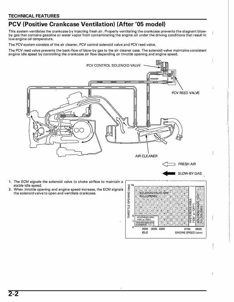
TECHNICAL FEATURES
PCV (Positive Crankcase Ventilation) (After '05 model) This system ventilates the crankcase by injecting fresh air. Properly ventilating the crankcase prevents the stagnant blowby gas that contains gasoline o r water vapor from contaminating the engine oil under the driving conditions that result in low engine oil temperature.
The PCV system consists of the air cleaner, PCV control solenoid valve and PCV reed valve.
The PCV reed valve prevents the back-flow of blow-by gas to the air cleaner case. The solenoid valve maintains consistent engine idle speed by controlling the crankcase air flow depending on throttle opening and engine speed.
AIR CLEANER
PCV REED VALVE
¢::::J FRESH AIR
• BLOW-BY GAS
1 . The ECM signals the solenoid valve to choke airflow to maintain a ,--------------------, sta ble idle speed.
2. When throttle opening and engine speed increase, the ECM signals the solenoid valve to open and ventilate crankcase.
2-2
"' "' z z w 0. 0
� "' F' s
0 2000 3000 3300 IDLE
:� "' ;;
�� i� 6700 6800
ENGINE SPEED (rpm)

3. FRAME/BODY PANELS/EXHAUST SYSTEM
BODY PANEL LOCATIONS ........................... 3-2
SERVICE INFORMATION ······························ 3-3
TROUBLESHOOTING···································· 3-3
SEAT······························································· 3-4
SEAT RAIL······················································ 3-5
INNER COVER················································ 3-5
FRONT COVER ···············································3-6
FLOOR STEP ···················································3-7
UNDER COVER···············································3-8
REAR FENDER ················································3-8
MUFFLER ························································3-9
-
3-1
FRAME/BODY PANELS/EXHAUST SYSTEM
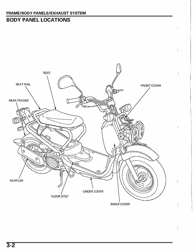
BODY PANEL LOCATIONS
SEAT RAIL FRONT COVER
MUFFLER
INNER COVER
3-2
FRAME/BODY PANELS/EXHAUST SYSTEM
SERVICE INFORMATION
GENERAL • This section covers removal and installation of the body panels, exhaust system and seat rail. • Always replace the exhaust pipe gasket with a new one after loosening or removing the exhaust pipe joint nuts. • When installing the exhaust system, loosely install all of the muffler fasteners. Always tighten the exhaust joint first,
then tighten the mounting fasteners. If you tighten the mounting fasteners first, the exhaust pipe may not seat properly. • Always i nspect the exhaust system for leaks after installation.
TROU BLESHOOTING Excessive exhaust noise • Broken exhaust system • Exhaust gas leak
Poor performance • Deformed exhaust system • Exhaust gas leak • Clogged muffler
3-3

FRAME/BODY PANELS/EXHAUST SYSTEM
SEAT
3-4
REMOVAL Open the seat by unhooking the seat hook. SEAT
Remove the two nuts and seat. SEAT
INSTALLATION Install the seat to the frame hooks and seat hinges ,--------------------, by aligning the seat hinge tabs with the frame hook HOD I<
grooveS as shown.
Tighten the nuts securely.
Close the seat.
FRAME/BODY PANELS/EXHAUST SYSTEM
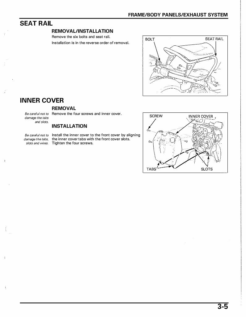
SEAT RAIL
REMOVAL/INSTALLATION Remove the six bolts and seat rail.
Installation is in the reverse order of removal.
INNER COVER
REMOVAL Be careful not to Remove the four screws and inner cover. damage the tabs
and slots.
INSTALLATION
Be careful not to Install the inner cover to the front cover by aligning damage the tabs, the inner cover tabs with the front cover slots.
slots and wires. Tighten the four screws.
SCREW
I ""'
SLOTS
3-5
FRAME/BODY PANELS/EXHAUST SYSTEM
FRONT COVER
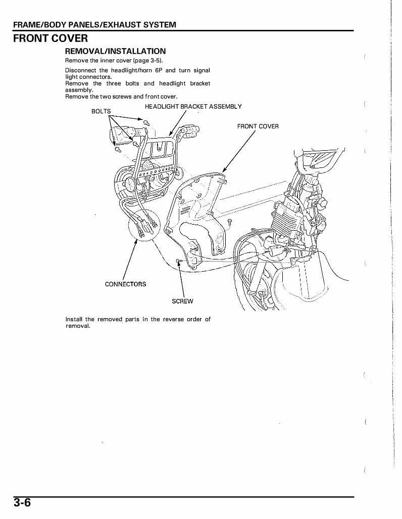
REMOVAL/INSTALLATION Remove the inner cover (page 3-5).
Disconnect the headlight/horn 6P and turn signal light connectors. Remove the three bolts and headlight bracket assembly. Remove the two screws and front cover.
HEADLIGHT BRACKET ASSEMBLY
3-6
BOLTS
Install the removed parts in the reverse order of removal.
FRONT COVER

FRAME/BODY PANELS/EXHAUST SYSTEM
FLOOR STEP
REMOVAL Remove the following:
- Seat rail (page 3-5). - Inner cover (page 3-5).
Remove the front mud guard. Remove the four screws, eight bolts/washers and floor step.
FRONT MUD GUARD
SCREWS
INSTALLATION Be careful not to Install the floor step onto the frame.
damage the wires, Install and tighten the eight bolts/washers and four cables and hoses. screws.
Be careful not to deform the mud
guard.
Install the mud guard by aligning its tabs with the floor step slots as shown.
Install the following: - Inner cover( page 3-5). - Seat rail (page 3-5).
BOLTS/WASH ERS
SLOT
3-7

FRAME/BODY PANELS/EXHAUST SYSTEM
UNDER COVER
REMOVAL/INSTALLATION Remove the following:
- Floor step (page 3-7). - Fuel tank (page 6-28).
Be careful not to Open the fuel pump lid by releasing its hooks. damage the hooks. Disconnect the fuel pump 2P connector.
Release the main wire harness and throttle cable from the guide of the under cover.
Be careful not to Remove the brake cable clamp bolt/washer while damage the brake holding the clamp.
cable. Remove the under cover.
Route the wire har- Install the removed parts in the reverse order of ness, cables and removal.
hoses properly (page 1-15).
REAR FENDER
REMOVAL/INSTALLATION
(
2P CONNECTOR
BOLT/WASHER
BRAKE CABLE TH ROTTLE CABLE
Release the carburetor vacuum hose from the ,--------------------, clamp. CARBURETOR VACUUM HOSE
3-8
Remove the bolt, bolts/washers and rear fender. � Installation is in the reverse order of removal. ��..._,� REA\END:R �--�-�_-_.:::_-•. ···-_:
)---='�,.--�-- �". (� �\j � ,:� o\;:. . t
-,
BOLT BOLTS/WASHERS
MUFFLER
The muffler protector can be serviced
with the muffler installed on the
engine.
FRAME/BODY PANELS/EXHAUST SYSTEM
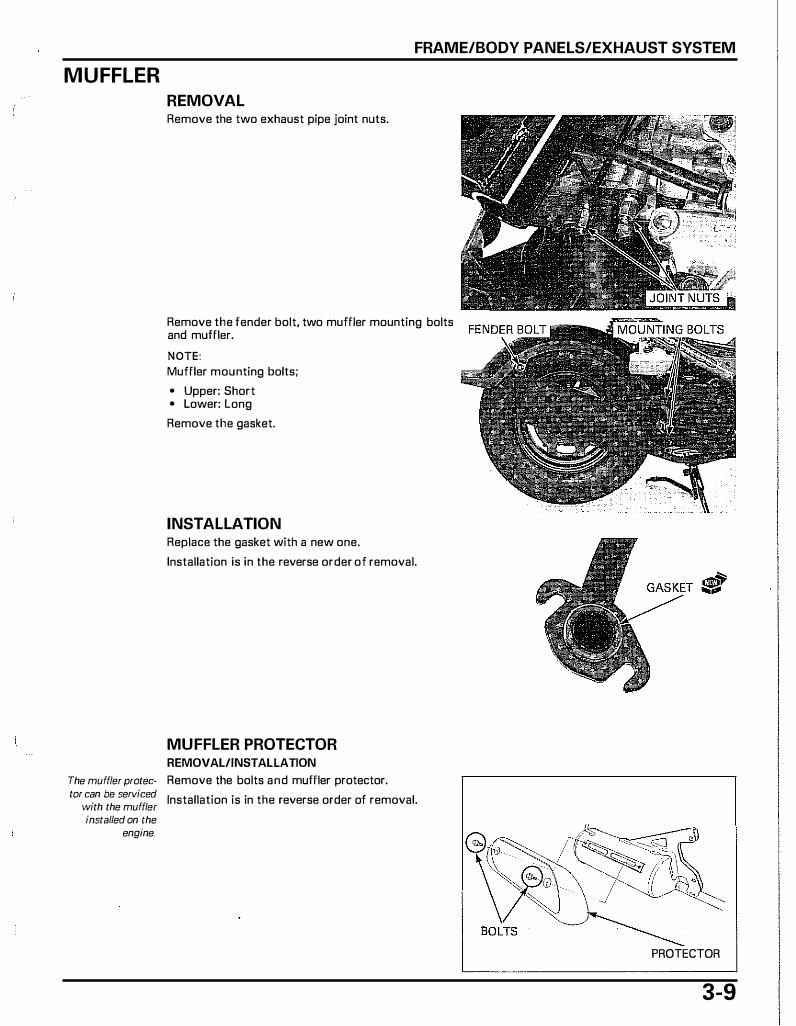
REMOVAL Remove the two exhaust pipe joint nuts.
Remove the fender bolt, two muffler mounting bolts and muffler.
NOTE: Muffler mounting bolts;
• Upper: Short • Lower: Long
Remove the gasket.
INSTALLATION Replace the gasket with a new one.
Installation is in the reverse order of removal.
MUFFLER PROTECTOR REMOVAL/INSTALlATION Remove the bolts and muffler protector.
Installation is in the reverse order of removal.
PROTECTOR
3-9

4. MAINTENANCE
..
SERVICE INFORMATION .............................. 4-2 COOLING SYSTEM ······································4-13
MAINTENANCE SCHEDULE························· 4-3 SECONDARY AIR SUPPLY SYSTEM ('03 - '05 modell············································4-14
FUEL LINE ...................................................... 4·4
SECONDARY AIR SUPPLY SYSTEM THROTTLE OPERATION································ 4-4 (After '05 model) ··········································4-15
AIR CLEANER················································· 4-5 BRAKE SHOES WEAR··································4-15
ENGINE BREATHER ...................................... 4-6 BRAKE SYSTEM ···········································4-16
SPARK PLUG ················································· 4-6 BRAKE LOCK OPERATION ··························4-16
VALVE CLEARANCE······································ 4-8 HEADLIGHT AIM ··········································4-17
ENGINE OIL·················································· 4-10 SUSPENSION ···············································4-17
ENGINE OIL STRAINER SCREEN ............... 4-12 NUTS, BOLTS, FASTENERS························4-18
ENGINE IDLE SPEED ··································· 4-12 WHEELS/TIRES ············································4-18
RADIATOR COOLANT ································· 4-13 STEERING HEAD BEARINGS ······················4-19
4-1
M AINTENANCE
SERVICE INFORMATION
GENERAL • Support the scooter with its centerstand o n a level surface before starting any work. • Gasoline is extremely flammable and is explosive under certain conditions. • Work in a well ventilated area. Smoking o r allowing flames or sparks in the work area or where the gasoline is stored
can cause a fire or explosion. • If the engine must be running to do some work, make sure the area is well ventilated. Never run the engine in an
enclosed area. • The exhaust contains poisonous carbon monoxide gas that may cause loss of consciousness and may lead to death.
Run the engine in an open area o r with an exhaust evacuation system in an enclosed area.
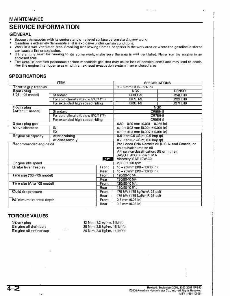
SPECIFICATIONS
ITEM SPECIFICATIONS Throttle grip freeplay 2 6 mm (1/16 1/4 in) Spark plug NGK DENSO ('03- '05 model) Standard CRBEH-9 U24FER9
For cold climate (below 5°C/41°F) CR7EH-9 U22FER9 For extended high speed riding CR9EH-9 U27FER9
Spark plug NGK (After '05 model) Standard CRBEH-9
For cold climate (below 5°C/41°F) CR7EH-9 For extended high speed riding CR9EH-9
Spark plug gap 0.80 - 0.90 mm (0.031 - 0.035 in) Valve clearance IN 0.10 + 0.03 mm (0.004 + 0.001 in)
EX 0.19 ± 0.03 mm (0.007 ± 0.001 in) Engine oil capacity After draining 0.6 liter (0.6 US qt, 0.5 Imp qt)
At disassembly 0.7 liter (0.7 US qt, 0.6 1mp qt) Recommended engine oil Pro Honda GN4 4-stroke oii (U.S.A. and Canada) or
an equivalent motor oil API service classification: SG or higher JASO T 903 standard: MA .. Viscosity: SAE 1 OW-30
Engine idle speed 2,000 + 100 rpm Brake lever free play Front 10 20 mm (3/8 13/16 in)
Rear 10 20 mm (3/8 13/16 in) Tire size ('03- '05 model) Front 1 20/90-10 54J
Rear 130/90-10 59J Tire size (After '05 model) Front 120/90-10 57J
Rear 1 30/90-10 61 J Cold tire pressure Front 175 kPa (1.75 kgf/cm2, 25 psi)
Rear 175 kPa (1.75 kgf/cm', 25 psi) Minimum tire tread depth Front 0.8 mm (0.03 in)
Rear 0.8 mm (0.03 in)
TORQUE VALUES
Spark plug Engine oil drain bolt Engine oil strainer cap
12 N·m (1.2 kgf·m, 9 1bf·ft) 25 N·m (2.5 kgf·m, 1 8 lbf·ft) 20 N·m (2.0 kgf·m, 14 1bf·ft)
4-2 Revised: September 2006, 2003-2007 NPS50 ©2006 American Honda Motor Co., Inc.- All Rights Reserved
MSV 11664 (0609)
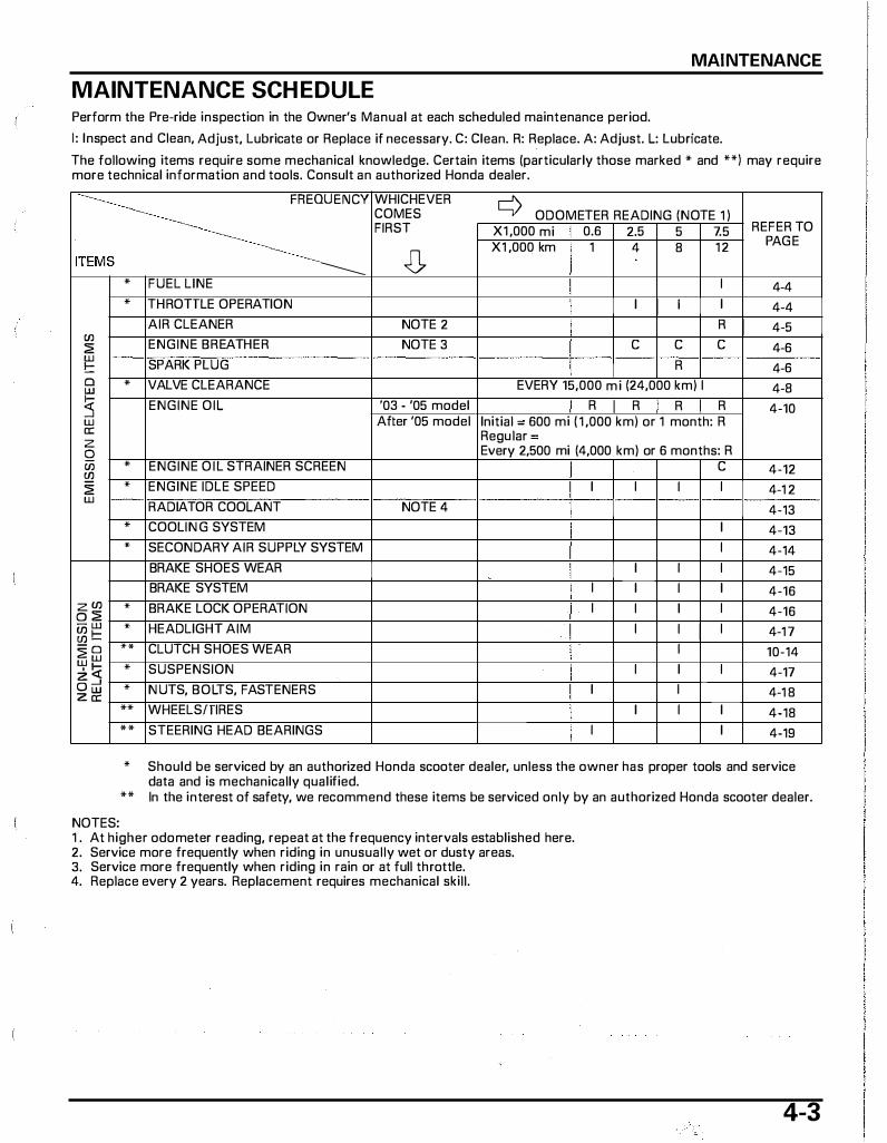
MAINTENANCE
MAINTENANCE SCH EDULE Perform the Pre-ride inspection in the Owner's Manual at each scheduled maintenance period.
1: Inspect and Clean, Adjust, Lubricate or Replace if necessary. C: Clean. R: Replace. A: Adjust. L: Lubricate.
The following items require some mechanical knowledge. Certain items (particularly those marked * and **) may require more technical information and tools. Consult an authorized Honda dealer.
·:., ·· ········· ·····... '''Q"''" ITEMS -------* FUEL LINE
* THROTILE OPERATION
AIR CLEANER Cll
ENGINE BREATHER � UJ
SPARK PLUG !::: 0 * VALVE CLEARANCE UJ � ENGINE OIL
UJ a: z Q Cll * ENGINE O IL STRAINER SCREEN � � * ENGINE IDLE SPEED UJ
RADIATOR COOLANT
* COOLIN G SYSTEM * SECONDARY AIR SUPPLY SYSTEM
BRAKE SHOES WEAR
BRAKE SYSTEM zCil * BRAKE LOCK OPERATION 0� - w * HEADLIGHT AIM Cllf--Cll-�0 ** CLUTCH SHOES WEAR UJUJ
·!;( * SUSPENSION z--' Ow * N UTS, BOLTS, FASTENERS Za:
** WHEELSfTIRES
** STEERING HEAD BEARINGS
WHICHEVER COMES FIRST
0 NOTE 2
NOTE 3
'03 - '05 model After '05 model
NOTE 4
¢ ODOMETER READING (NOTE 1 ) X1 ,000 mi 0.6 2.5 5 7.5 REFER TO
X1 ,000 km 1 4 8 1 2 PAGE
I 4-4 I I I I 4-4
R I 4-5 c c c 4-6
R 4-6 EVERY 15,000 mi (24,000 km) I 4-8
I R I R I R I R 4-10 Initial - 600 mi ( 1 ,000 km) or 1 month: R Regular = Every 2,500 mi (4,000 km) or 6 months: R
c 4-12 I I I I 4-1 2
4-13 I 4-13 I 4-14
I I I 4-15 I I I I 4-16 I I I I 4-16
I I I I 4-1 7 I 10-14
I I I 4-17 I I 4-1 8
I I I 4-18 I I 4-19
* Should be serviced by an authorized Honda scooter dealer, unless the owner has proper tools and service data and is mechanically qualified.
** In the interest of safety, we recommend these items be serviced only by an authorized Honda scooter dealer.
NOTES: 1 . At higher odometer reading, repeat at the frequency intervals established here. 2. Service more frequently when riding in unusually wet or dusty areas. 3. Service more frequently when riding in rain or at full throttle. 4. Replace every 2 years. Replacement requires mechanical skill.
4-3
MAINTENANCE
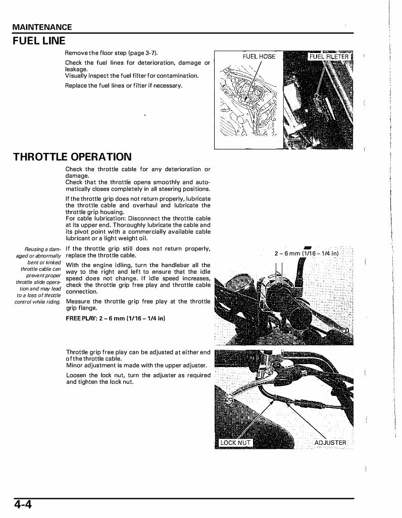
FUEL LINE Remove the floor step (page 3-7).
Check the fuel lines for deterioration, damage or leakage. Visually inspect the fuel filter for contamination.
Replace the fuel lines or filter if necessary.
THROTTLE OPERATION
Reusing a damaged or abnormally
bent or kinked throttle cable can
prevent proper throttle slide opera
tion and may lead to a loss of throttle
Check the throttle cable for any deterioration or damage. Check that the throttle opens smoothly and automatically closes completely in all steering positions.
If the throttle grip does not return properly, lubricate the throttle cable and overhaul and lubricate the throttle grip housing. For cable lubrication: Disconnect the throttle cable at its upper end. Thoroughly lubricate the cable and its pivot point with a commercially available cable lubricant or a light weight oil.
If the throttle grip sti ll does not return properly, replace the throttle cable.
With the engine idling, turn the handlebar all the way to the right and left to ensure that the idle speed does not change. I f idle speed increases, check the throttle grip free play and throttle cable connection.
control while riding. Measure the throttle grip free play at the throttle grip flange.
4-4
FREE PLAY: 2 - 6 mm (1/16 - 1/4 in)
Throttle grip free play can be adjusted at either end of the throttle cable. Minor adjustment is made with the upper adjuster.
Loosen the lock nut, turn the adjuster as required and tighten the lock nut.
1111111 2 - 6 mm (1/1 6 - 1 /4 in)
ADJUSTER
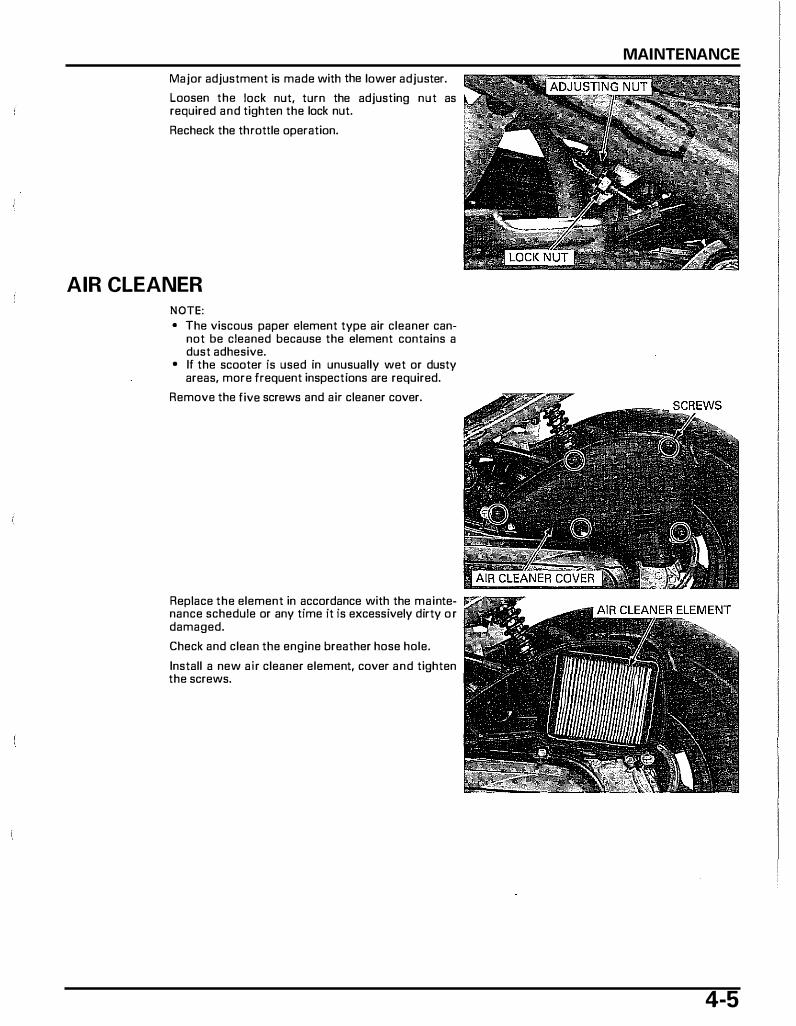
Major adjustment is made with the lower adjuster.
Loosen the lock nut, turn the adjusting nut as required and tighten the lock nut.
Recheck the throttle operation.
AIR CLEANER NOTE: • The viscous paper element type air cleaner can
not be cleaned because the element contains a dust adhesive.
• If the scooter is used in unusually wet or dusty areas, more frequent inspections are required.
Remove the five screws and air cleaner cover.
Replace the element in accordance with the maintenance schedule or any time it is excessively dirty o r damaged.
Check and clean the engine breather hose hole.
Install a new air cleaner element, cover and tighten the screws.
MAINTENANCE
4-5
MAINTENANCE
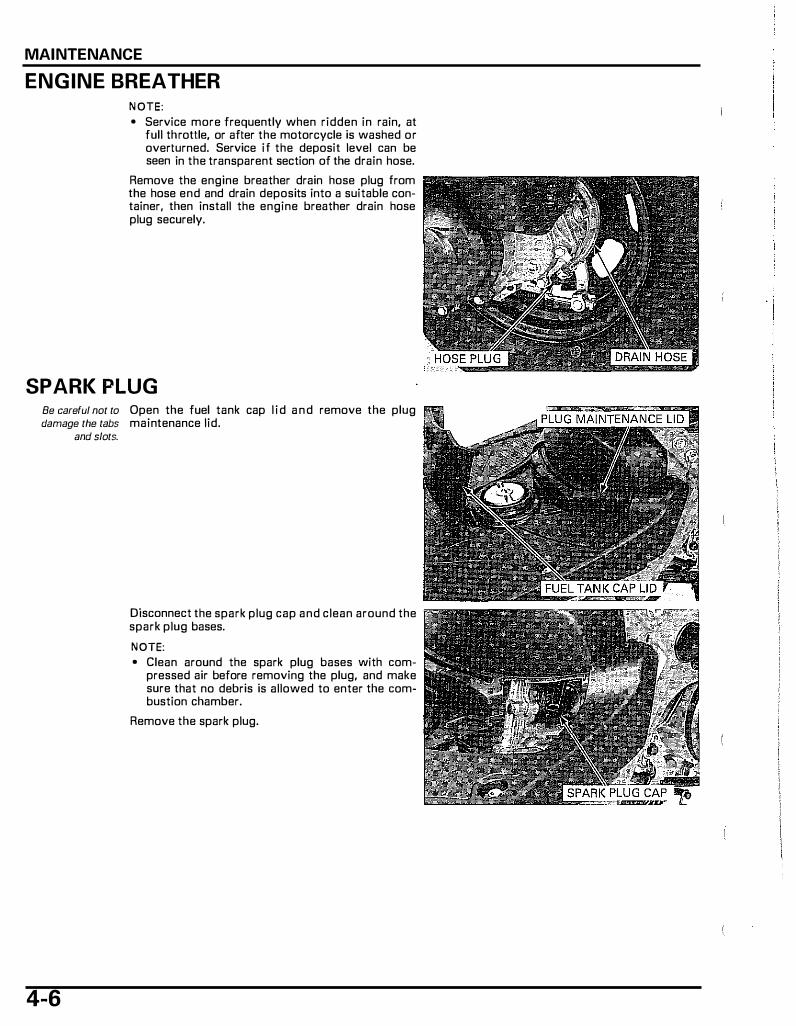
ENGINE BREATHER NOTE: • Service more frequently when ridden in rain, at
full throttle, or after the motorcycle is washed or overturned. Service if the deposit level can be seen in the transparent section of the drain hose.
Remove the engine breather drain hose plug from the hose end and drain deposits into a suitable container, then install the engine breather drain hose plug securely.
SPARK PLUG Be careful not to Open the fuel tank cap l id and remove the plug damage the tabs maintenance lid.
and slots.
4-6
Disconnect the spark plug cap and clean around the spark plug bases.
NOTE: • Clean around the spark plug bases with com
pressed air before removing the plug, and make sure that no debris is allowed to enter the combustion chamber.
Remove the spark plug.
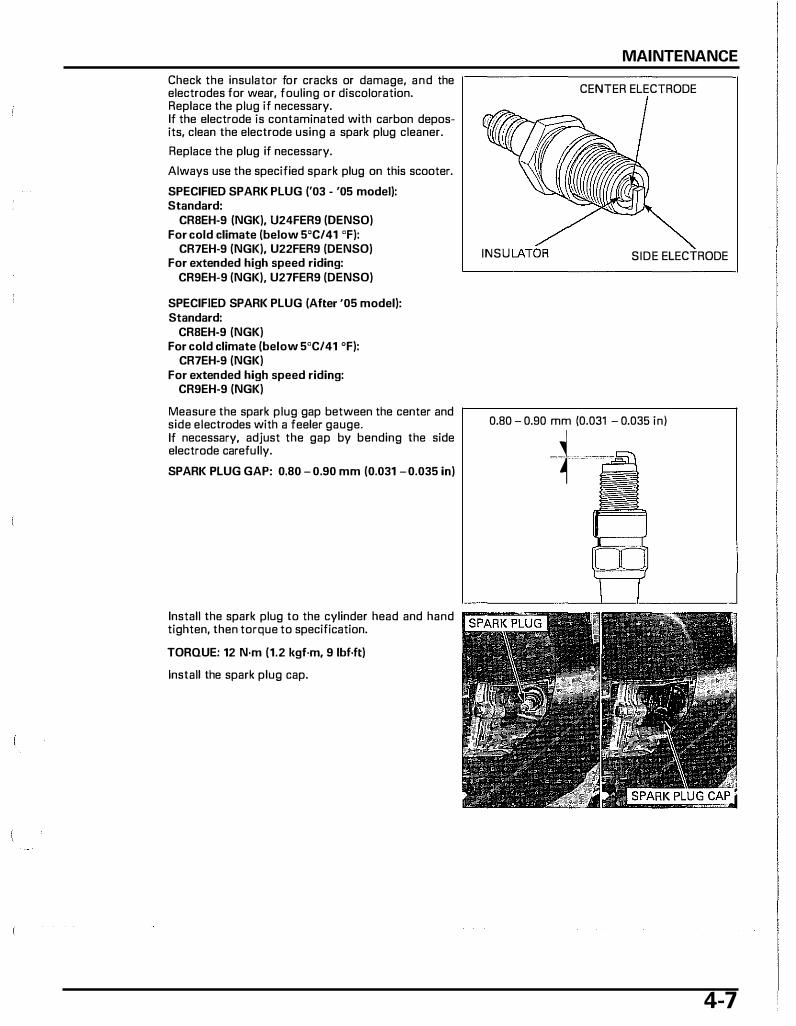
Check the insulator for cracks or damage, and the electrodes for wear, fouling o r discoloration. Replace the plug if necessary. If the electrode is contaminated with carbon deposits, clean the electrode using a spark plug cleaner.
Replace the plug if necessary.
Always use the specified spark plug on this scooter.
SPECIFIED SPARK PLUG ('03 - '05 model): Standard:
CRBEH-9 (NGK), U24FER9 (DENSO) For cold climate (below 5'C/41 'F):
CR7EH-9 (NGK), U22FER9 (DENSO) For extended high speed riding:
CR9EH-9 (NGK). U27FER9 (DENSO)
SPECIFIED SPARK PLUG (After '05 model): Standard:
CRBEH-9 (NGK) For cold climate (below 5'C/41 'F):
CR7EH-9 (NGK) For extended high speed riding:
CR9EH-9 (NGK)
Measure the spark plug gap between the center and side electrodes with a feeler gauge. If necessary, adjust the gap by bending the side electrode carefully.
SPARK PLUG GAP: 0.80 - 0.90 mm (0.031 -0.035 in)
Install the spark plug to the cylinder head and hand tighten, then torque to specification.
TORQUE: 12 N·m (1.2 kgf·m, 9 lbf·ft)
Install the spark plug cap.
MAINTENANCE
CENTER ELECTRODE
INSU SIDE ELECTRODE
0.80 - 0.90 mm (0.031 - 0.035 in)
��, ' E\
4-7
MAINTENANCE
Be careful not to Install the plug maintenance lid. damage the tabs Close the fuel tank cap lid.
and slots.
VALVE CLEARANCE
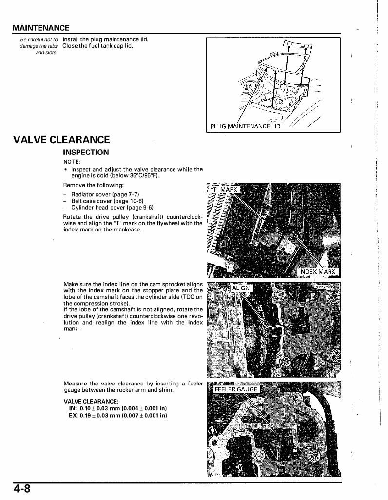
INSPECTION NOTE:
4-8
• Inspect and adjust the valve clearance while the engine is cold (below 35"C/95"F).
Remove the following:
- Radiator cover (page 7-7) - Belt case cover (page 1 0-6) - Cylinder head cover (page 9-6)
Rotate the drive pulley (crankshaft) counterclockwise and align the "T" mark on the flywheel with the index mark on the crankcase.
Make sure the index line on the cam sprocket aligns with the index mark on the stopper plate and the lobe of the camshaft faces the cylinder side (TDC on the compression stroke). If the lobe of the camshaft is not aligned, rotate the drive pulley (crankshaft) counterclockwise one revolution and realign the index line with the index marie
Measure the valve clearance by inserting a feeler gauge between the rocker arm and shim.
VALVE CLEARANCE: IN: 0.10 ± 0.03 mm (0.004 ± 0.001 in) EX: 0.19 ± 0.03 mm (0.007 ± 0.001 in)
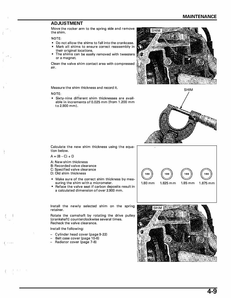
ADJUSTMENT Move the rocker arm to the spring side and remove the shim.
NOTE: • Do nat allow the shims to fall into the crankcase. • Mark a l l shims to ensure correct reassembly in
their original locations. • The shims can be easily removed with tweezers
or a magnet.
Clean the valve shim contact area with compressed air.
Measure the shim thickness and record it.
NOTE: • Sixty-nine different shim thicknesses are avail
able in increments of 0.025 mm (from 1 .200 m m t o 2.900 m m ) .
Calculate the new shim thickness using t h e equation below.
A = (8 - C) + D
A: New shim thickness B: Recorded valve clearance C: Specified valve clearance D: Old shim thickness
• Make sure of the correct shim thickness by measuring the sh im with a micrometer.
• Reface the valve seat if carbon deposits result in a calculated d imension of over 2.900 mm.
Install the newly selected shim on the spring retainer.
Rotate the camshaft by rotating the drive pulley (crankshaft) counterclockwise several times. Recheck the valve clearance.
Install the following:
- Cylinder head cover (page 9-22) - Belt case cover (page 1 0-6) - Radiator cover (page 7-8)
MAINTENANCE
SHIM
e e e e 1.80 mm 1.825 m m 1.85 m m 1 .875 m m
4-9

MAINTENANCE
E NGINE OIL OIL LEVEL CHECK Start the engine and let it idle for 3-5 minutes.
Stop the engine and wait 2-3 minutes.
Support the scooter with its centerstand on a level surface. Remove the oil filler cap/dipstick and wipe the oil from the dipstick with a clean cloth.
Insert the dipstick without screwing it in, remove it ,---------;---;-----------,
4- 1 0
and check the oil level.
If the oil level is below or near the lower level line on the dipstick, add the recommended oil to the upper level.
RECOMMENDED ENGINE OIL: Pro Honda GN4 4-stroke oil (U.S.A. and Canada) or an equivalent motor oil API service classification: SG or higher JASO T 903 standard: MA @�!#jiM Viscosity: SAE 10W�30
NOTE: • Other viscosities shown in the chart may be used
when the average temperature in your riding area is within the indicated range.
Reinstall the oil filler cap/dipstick.
For engine oil change, page 4-1 1 .
UPPER ..._ LEVEL
LOWER LEVEL
-20 0 20 40 60 BO 100 120"F
Revised: September 2006, 2003-2007 NPS50 ©2006 American Handa Motor Co., Inc. - All Rights Reserved
MSV 11664 (0609)
I I
OIL CHANGE NOTE: • Change the oil with the engine warm and the
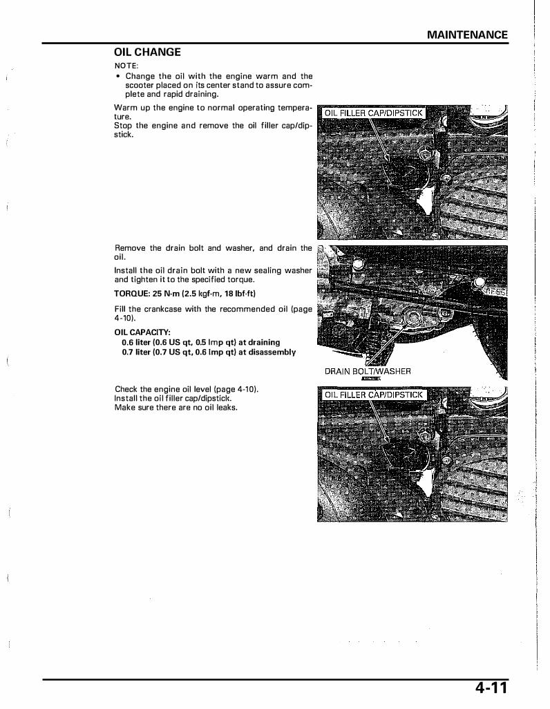
scooter placed on its center stand to assure com� plete and rapid draining.
Warm up the engine to normal operating tempera- l'(ji'L'Ri'.U�::\Pi[};STi'CK ture. Stop the engine and remove the oil filler cap/dipstick.
Remove the drain bolt and washer, and drain the oil.
Install the oil drain bolt with a new sealing washer and tighten it to the specified torque.
TORQUE: 25 N-m (2.5 l<gf·m, 18 lbf.ft)
Fill the crankcase with the recommended oil (page 4-10).
OIL CAPACITY: 0.6 liter (0.6 US qt, 0.5 Imp qt) at draining 0.7 liter (0.7 US qt, 0.6 1mp qt) at disassembly
Check the engine oil level (page 4-1 0). Install the oil filler cap/dipsticl<. Make sure there are no oil leaks.
MAINTENANCE
4-1 1
MAINTENANCE
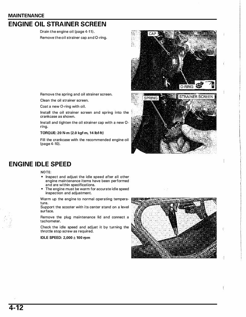
ENGINE OIL STRAINER SCREEN Drain the engine oi l (page 4-1 1 ) .
Remove the o i l strainer cap and 0-ring.
Remove the spring and oil strainer screen.
Clean the oil strainer screen.
Coat a new D-ring with oil.
Install the oi l strainer screen and spring i nto the crankcase as shown.
Install and tighten the oil strainer cap with a new 0-ring.
TORQUE: 20 N·m (2.0 kgf·m, 14 lbf.ft)
Fill the crankcase with the recommended engine oil (page 4-10).
ENGINE IDLE SPEED
4-1 2
NOTE: • Inspect and adjust the idle speed after all other
engine maintenance items have been performed and are within specifications.
• The engine must be warm for accurate idle speed inspection and adjustment.
Warm up the engine to normal operating temperature. Support the scooter with its center stand on a level surface.
Remove the plug maintenance lid and connect a tachometer.
Check the idle speed and adjust it by turning the throttle stop screw as required.
IDLE SPEED: 2,000 ± 100 rpm

Disconnect the tachometer and install the plug maintenance lid removed parts.
RADIATOR COOLANT Support the scooter with its center stand on a level surface.
Check the coolant level of the reserve tank with the engine running at normal operating temperature. The level should be between the "UPPER" and "LOWER" level lines with the scooter upright on a level surface.
If the level is low, remove the reserve tank cap and fill the tank to the "UPPER" level l ine with a 1 :1 mixture of distilled water and antifreeze (coolant mixture preparation: page 7-5).
I NOTICE I Using coolant with silicate inhibitors may cause pre- L:;��;:,i�:i:;,.:o::;� mature wear of water pump seals or blockage of radiator passages. Using tap water may cause engine damage.
Check to see if there are any coolant leaks when the coolant level decreases very rapidly. If the reserve tank becomes completely empty, there is the possibility of air getting into the cooling system (page 7-7).
COOLING SYSTEM
MAINTENANCE
4-1 3
MAINTENANCE
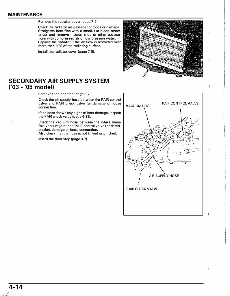
Remove the radiator cover (page 7-7).
Check the radiator air passage for clogs or damage. Straighten bent fins with a small, flat blade screwdriver and remove insects, mud or ather obstructions with compressed air o r low pressure water. Replace the radiator if the air flow is restricted over more than 20% of the radiating surface.
Install the radiator cover (page 7-8).
S ECONDARY AIR SUPPLY SYSTEM ('03 - '05 model)
Remove the floor step (page 3-7).
Check the air supply hose between the PAIR control valve and PAIR check valve for damage or loose connection. VACU UM HOSE
If the hose shows any signs of heat damage, inspect the PAIR check valve (page 6-23).
Check the vacuum hose between the intake manifold vacuum joint and PAIR control valve for deterioration, damage or loose connection. Also check that the hose is not kinked or pinched.
Install the floor step (page 3-7).
PAIR CONTROL VALVE
AIR SUPPLY HOSE
PAIR CHECI< VALVE
4- 1 4

SECONDARY AIR SU PPLY SYSTEM (After '05 model)
Remove the floor step (page 3-7).
Check the air supply hose between the air cleaner housing and PAIR check valve for damage or loose connection.
If the hose shows any signs of heat damage, inspect the PAIR check valve (page 6-23).
Install the floor step (page 3-7).
I I
PAIR CHECI< VALVE
BRAKE SHOES WEAR Check the brake shoes and brake drum if the arrow ro;;n;rr. on the indicator plate aligns with the "6'' mark on the brake panel when the brake lever is squeezed.
NOTE: • If no adjustment remains before the wear indica
tor l imit is reached, this indicates excessive wear and the brake shoes need to be replaced.
Refer to page 14-11 for front brake shoes replacement.
Refer to page 1 5-4 for rear brake shoes replacement.
MAINTENANCE
AIR SUPPLY HOSE
MAINTENANCE
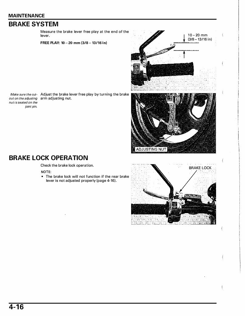
BRAKE SYSTEM Measure the brake lever free play at the end of the lever.
FREE PLAY: 10 - 20 mm (3/8 - 13/16 in)
Make sure the cut- Adjust the brake lever free play by turning the brake out on the adjusting arm adjusting nut. nut is seated on the
joint pin.
BRAKE LOCK OPERATION
4- 1 6
Check the brake lock operation.
NOTE: • The brake lock will not function if the rear brake
lever is not adjusted properly (page 4-16).
1 0 - 20 mm (3/8 - 13/16 in)
BRAKE LOCK
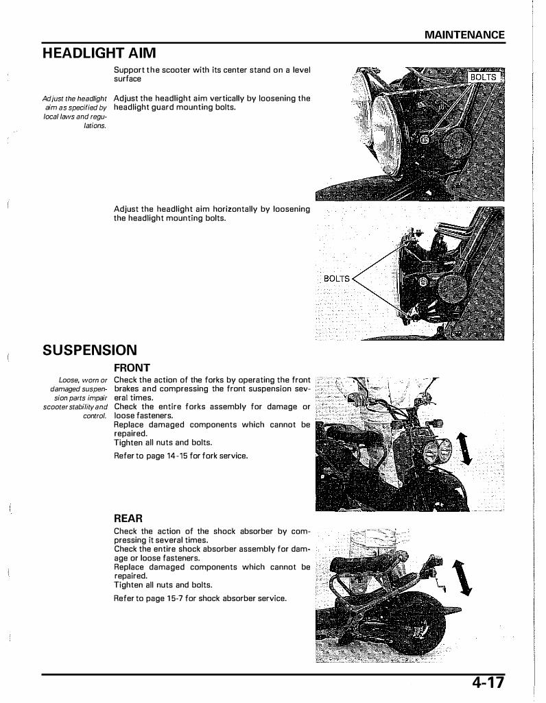
H EADLIGHT AIM Support the scooter with its center stand on a level surface
Adjust the headlight Adjust the headlight aim vertically by loosening the aim as specified by headlight guard mounting bolts.
local Jaws and regu-lations.
Adjust the headlight aim horizontally by loosening the headlight mounting bolts.
SUSPENSION
FRONT Loose, worn or Check the action of the forks by operating the front
damaged suspen- brakes and compressing the front suspension sevsion parts impair era\ times.
scooter stability and Check the entire forks assembly for damage or control. loose fasteners.
Replace damaged components which cannot be repaired. Tighten all nuts and bolts.
Refer to page 14-15 for fork service.
REAR Check the action of the shock absorber by compressing it several times. Check the entire shock absorber assembly for damage or loose fasteners. Replace damaged components which cannot be repaired. Tighten all nuts and bolts.
Refer to page 1 5-7 for shock absorber service.
MAINTENANCE
4-1 7
MAINTENANCE
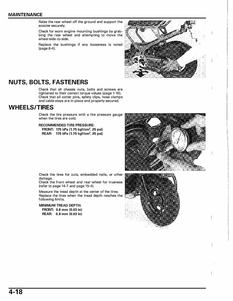
Raise the rear wheel off the ground and support the scooter securely.
Check for worn engine mounting bushings by grabbing the rear wheel and attempting to move the wheel side-to-side.
Replace the bushings if any looseness is noted (page 8-4).
NUTS, BOLTS, FASTENERS Check that all chassis nuts, bolts and screws are tightened to their correct torque values (page 1-10). Check that all cotter pins, safety clips, hose clamps and cable stays are in place and properly secured.
WHEELS/TIRES
4-1 8
Check the tire pressure with a tire pressure gauge when the tires are cold.
RECOMMENDED TIRE PRESSURE: FRONT: 175 I<Pa (1.75 kgf/cm2, 25 psi) REAR: 175 kPa (1.75 l<gf/cm2, 25 psi)
Check the tires for cuts, embedded nails, or other damage. Check the front wheel and rear wheel for trueness (refer to page 14-7 and page 1 5-4).
Measure the tread depth at the center of the tires. Replace the tires when the tread depth reaches the following limits.
MINIMUM TREAD DEPTH: FRONT: 0.8 mm (0.03 in) REAR: 0.8 mm (0.03 in)
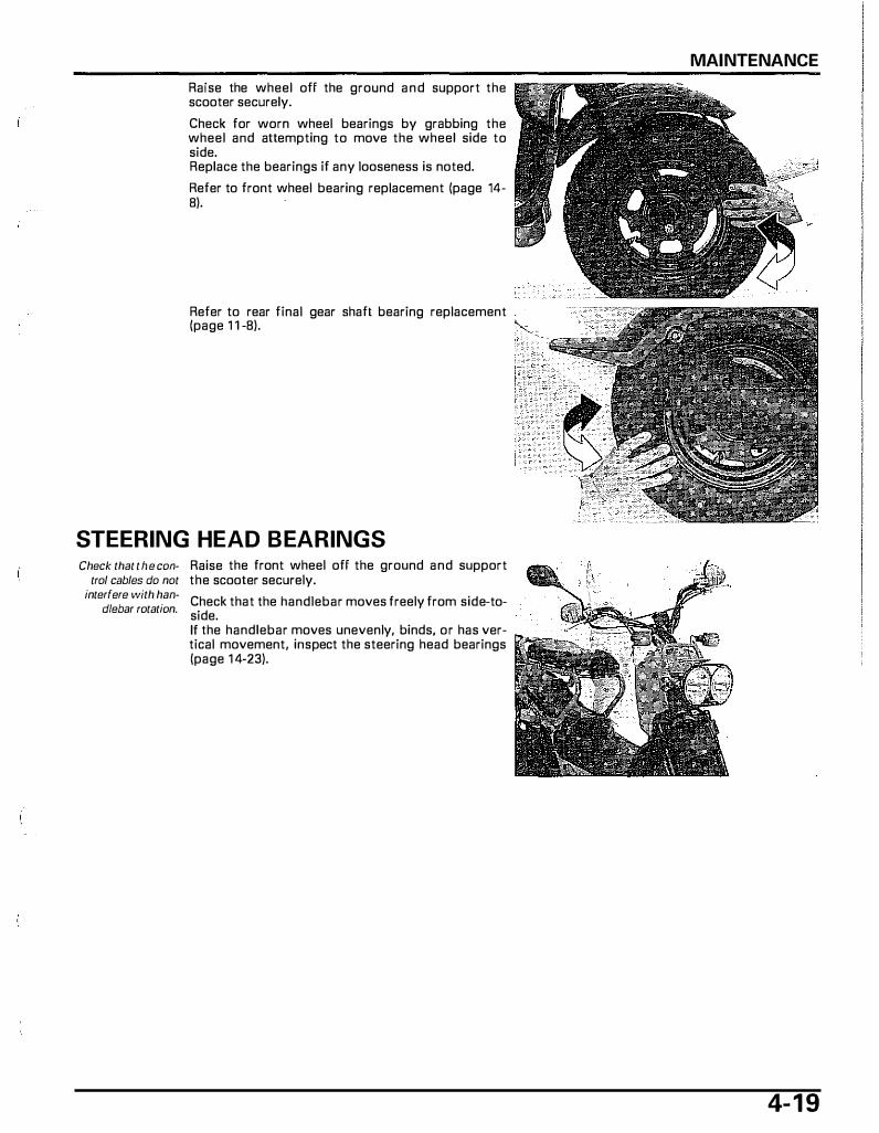
Raise the wheel off the ground and support the scooter securely.
Check for worn wheel bearings by grabbing the wheel and attempting to move the wheel side to side. Replace the bearings if any looseness is noted.
Refer to front wheel bearing replacement (page 14-8).
Refer to rear final gear shaft bearing replacement (page 1 1 -8).
STEERING HEAD BEARINGS Check that the con
trol cables do not interfere with han
dlebar rotation.
Raise the front wheel off the ground and support the scooter securely.
Check that the handlebar moves freely from side-toside. If the handlebar moves unevenly, binds, or has vertical movement, inspect the steering head bearings (page 1 4-23).
MAINTENANCE
4- 1 9
5. LUBRICATION SYSTEM
.. LUBRICATION SYSTEM DIAGRAM ············· 5-2 TROUBLESHOOTING . . . . . . . . . . . . . . . . . . . . . . . . . . . . . . . . . . . . ,5-3
SERVICE INFORMATION . . . . . . . . . . . . . . . . . . . . . . . . . . . . . . 5-3 OIL PUMp . . . . . . . . . . . . . . . . . . . . . . . . . . . . . . . . . . . . . . . . . . . . . . . . . . . . . . . . 5-4
5-1

LUBRICATION SYSTEM
LUBRICATION SYSTEM DIAGRAM
CRAN !<SHAFT ROCKER ARM SHAFT
•
PISTON
ROCKER ARM
OIL STRAINER
5-2
LUBRICATION SYSTEM
SERVICE INFORMATION
GENERAL
A CAUTION Used engine oil may cause skin cancer if repeatedly left in contact with the skin for prolonged periods, Although this is unl ikely unless you handle used oil on a daily basis, it is still advisable to thoroughly wash your hands with soap and water as soon as possible after handling used oi l .
• The oil pump can be serviced with the engine installed i n the frame. • The service procedures i n this section must be performed with the engine oil drained. • When removing and installing the oil pump, use care not to altow dust or dirt to enter the engine. • If any portio n of the oil p um p is worn beyond the specified service limits, replace the oil pump as an assembly. • After the oil pump has been installed, check that there are no oil leaks.
SPECIFICATIONS Unit· mm (In)
ITEM STANDARD SERVICE LIMIT Engine oil capacity I At draining 0.6 liter (0,6 US qt, 0.5 1mp qt) -
At disassembly 0.7 liter (0.7 US qt, 0.61mp qt) Recommended engine oi l Pro Honda GN4 4-stroke oi l (U.S.A. and Canada) or an equivalent
motor oil API service classification: SG or higher JASO T 903 standard: MA EIB Viscosity: SAE 1 OW-30
O i l pump rotor Tip clearance 0.15 (0.006) Body clearance 0,1 5 - 0.20 (0.006 - 0.008) Side clearance 0.05 0.10 (0.002 0.0041
TORQUE VALUES
Oil pump cover screw 2.0 N·m (0.2 kgf·m, 1.4 1bf·!tl
TROUBLESHOOTING Engine oil level too low • O i l consumption • External oil leak • Wor n piston ring or incorrect piston ring installation • Worn cylinder • Worn valve guide or seal
Oil contamination • O i l not changed often enough • Fau lty cylinder head gasket • Worn piston ring
Revised: September 2006, 2003�2007 NPS50 ©2006 American Honda Motor Co., Inc. - All Rights Reserved MSV 11664 (0609)
0.20 (0.008) 0.22 (0.009) 0.12 (0.0051
5-3
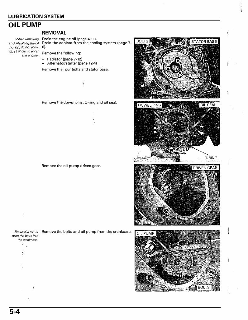
LU BRICATION SYSTEM
OIL PUMP
When removing and installing the oil pump, do not alfow dust or dirt to enter
the engine.
REMOVAL Drain the engine oi l (page 4-1 1 ) . Drain the coolant from the cooling system (page 7-6).
Remove the following:
- Radiator (page 7-12) - Alternator/starter (page 1 2-4)
Remove the four bolts and stator base.
Remove the dowel pins, D-ring and oil seal.
Remove the oi l pump d riven gear.
Be careful not to Remove the bolts and oi l pump from the crankcase. drop the bolts into
the crankcase.
5-4
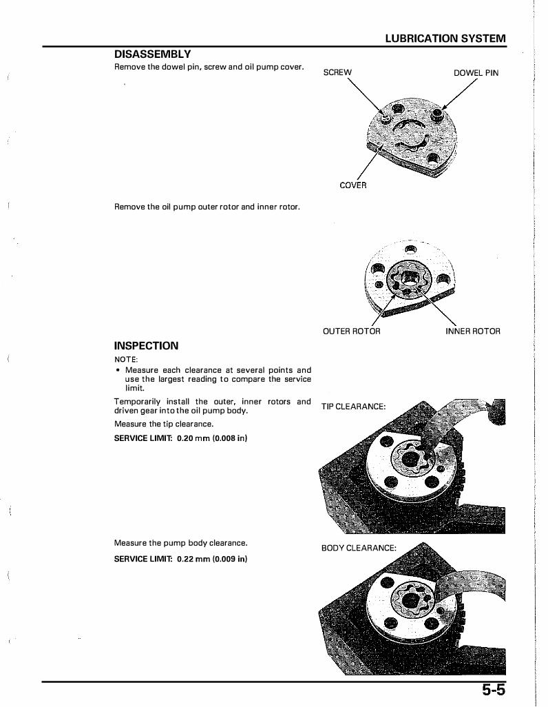
DISASSEMBL V Remove the dowel pin, screw and oil pump cover.
Remove the oil pump outer rotor and inner rotor.
INSPECTION NOTE: • Measure each clearance at several points and
use the largest reading to compare the service l imit.
Temporarily install the outer, inner rotors and driven gear into the oil pump body.
Measure the tip clearance.
SERVICE LIMIT: 0.20 mm (0.008 in)
Measure the pump body clearance.
SERVICE LIMIT: 0.22 mm (0.009 in)
LUBRICATION SYSTEM
SCREW DOWEL PIN
OUTER ROTOR INNER ROTOR
TIP CLEARANCE:
BODY CLEARANCE:
LUBRICATION SYSTEM
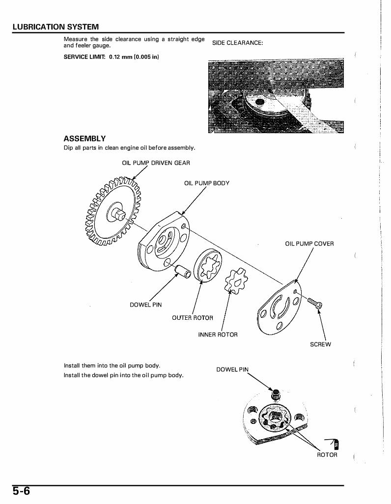
Measure the side clearance using a straight edge and feeler gauge.
SERVICE LIMIT: 0.12 mm (0.005 in)
ASSEMBLY Dip all parts in clean engine oil before assembly.
OIL PUMP DRIVEN GEAR
SIDE CLEARANCE:
OIL PUMP BODY
DOWEL PIN
INNER ROTOR
Install them into the oil pump body. DOWEL PIN
Install the dowel pin i nto the oil pump body. �-til -w::�
5 -6
OIL PUMP COVER
SCREW
-, ROTOR
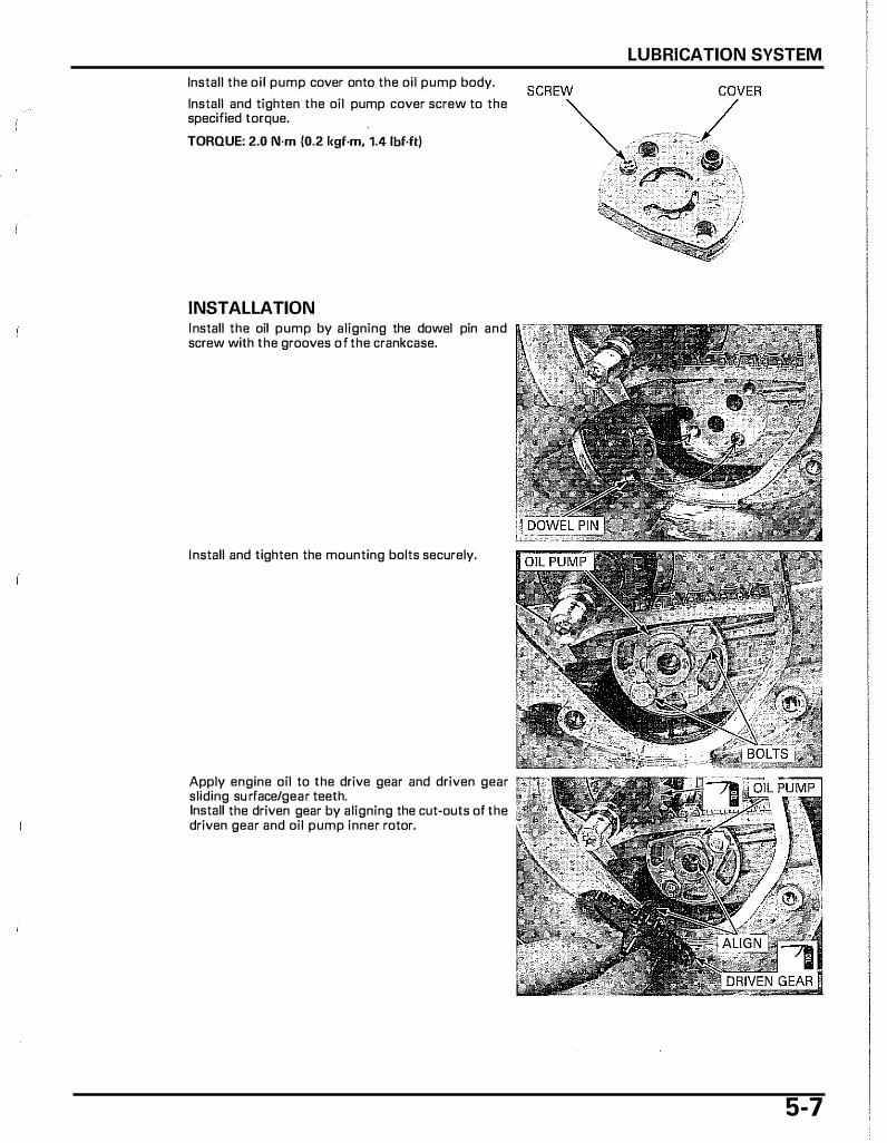
Install the oi l pump cover onto the oil pump body.
Install and tighten the oil pump cover screw to the specified torque.
TORQUE: 2.0 N·m (0.2 i<gf·m, 1.4 lbf.ft)
INSTALLATION Install the oil pump by aligning the dowel pin and screw with the grooves of the crankcase.
Install and tighten the mounting bolts securely.
Apply engine oil to the drive gear and driven gear sliding su rface/gear teeth. Install the driven gear by aligning the cut-outs of the driven gear and oil pump inner rotor.
LUBRICATION SYSTEM
5-7

LUBRICATION SYSTEM
5-8
Apply engine oil to a new oil seal l ip and install it into the stator base. Coat a new D-ring with oil and install it into the stator base.
Apply engine oil to the oil pump driven gear sliding surface of the stator base.
Install the dowel pins into the crankcase.
Install the stator base on the crankcase and tighten ..,. ..... ...,. the four bolts securely.
Install the following:
- Alternator/starter (page 1 2-5) - Radiator (page 7-13)
Fill and bleed the cooling system (page 7-7).
After installation, fill the crankcase with the recommended engine oi l (page 4-10) and check that there are no oil leaks.
COMPONENT LOCATIONs . . . . . . . . . . . . . . . . . . . . . . . . . . . 6-2
SERVICE INFORMATION . . . . . . . . . . . . . . . . . . . . . . . . . . . . . . 6-3
TROUBLESHOOTING . . . . . . . . . . . . . . . . . . . . . . . . . . . . . . . . . . . . 6-4
AIR CLEANER HOUSING . . . . . . . . . . . . . . . . . . . . . . . . . . . . . . 6-5
CARBURETOR REMOVAL . . . . . . . . . . . . . . . . . . . . . . . . . . . . . 6-7
CARBURETOR DISASSEMBLY . . . . . . . . . . . . . . . . . . . . . 6-8
CARBURETOR ASSEMBLy . . . . . . . . . . . . . . . . . . . . . . . . . 6-12
CARBURETOR INSTALLATION . . . . . . . . . . . . . . . . . . 6-15
6. FUEL SYSTEM
PILOT SCREW ADJUSTMENT ('03 - 'OS model) . . . . . . . . . . . . . . . . . . . . . . . . . . . . . . . . . . . . . . . . . . . . 6-18
PILOT SCREW ADJUSTMENT {After '05 model) . . . . . . . . . . . . . . . . . . . . . . . . . . . . . . . . . . . . . . . . . . 6-19
HIGH ALTITUDE ADJUSTMENT {After '05 model) . . . . . . . . . . . . . . . . . . . . . . . . . . . . . . . . . . . . . . . . . . 6-20
STARTING ENRICHMENT {SE) VALVE . . . . . . . 5-21
SECONDARY AIR SUPPLY SYSTEM . . . . . . . . . . 6-22
PCV CONTROL SOLENOID VALVE/ PCV REED VALVE {After '05 model) . . . . . . . . . . . 6-24
FUEL TANK . . . . . . . . . . . . . . . . . . . . . . . . . . . . . . . . . . . . . . . . . . . . . . . . . . . 6-28
I ..
6-1

FUEL SYSTEM
COMPONENT LOCATIONS
AFTER '05 MODEL:
6-2
SERVICE INFORMATION
GENERAL
FUEL SYSTEM
• Work in a well ventilated area. Smoking or allowing flames or sparks in the work area or where gasoline is stored can cause a fire or explosion.
• For fuel pump inspection, refer to page 1 9-18. • For throttle sensor inspection, refer to page 17-8. • When disassembling fuel system parts, note the locations of the 0-rings. Replace them with new ones on reassembly. • Before disassembling the carburetor, place a suitable container under the carburetor drain hose. Loosen the screw and
drain the carburetor. • After removing the carburetor, wrap the intake port of the engine with a shop towel or cover it with pieces of tape to
prevent any foreign material from dropping into the engine.
SPECIFICATIONS
ITEM I Carburetor identification number ( '03 - '05 model) Carburetor identification number (Alter '05 model) Main jet Slow jet Pilot screw initial opening Float level Idle speed Starting enrichment (SE) valve resistance (20°C/68°F) Throttle grip free play
TORQUE VALUES
Float chamber screw Vacuum chamber cover screw SE valve setting plate screw Insulator band screw (Alter '05 model)
TOOLS
Carburetor float level gauge 07401-0010000
I
2.1 N·m (0.21 kgf·m, 1.5 lbf·lt) 2.1 N·m (0.21 kgf·m, 1.5 1bf·lt) 2.1 N·m (0.21 kgf·m, 1.5 lbf·lt) 3.0 N·m (0.30 kgf·m, 2.2 lbf·lt)
Pilot screw wrench 071<MA-MS60101
or 07MMA-MT3010B or 07MMA-MT3010A (U.S.A. only)
SPECIFICATIONS NVKOOG NVKOOH
#75 #35 X #35
2-1/4 turns out 13 mm (0.5 in)
2,000 ± 100 rpm 2.8 5.2 !.l
2 - 6 mm (1/16 - 1 /4 in)
6-3
FUEL SYSTEM
TROUBLESHOOTING Engine won't start • No fuel in tank • No fuel to carburetor
- Clogged fuel filter - Clogged fuel hose - Clogged fuel cap breather hole - Faulty fuel pump (page 1 9-18)
• Too much fuel getting to the engine - Clogged air cleaner - Flooded carburetor
• Intake air leak • Contaminated/deteriorated fuel • Faulty starting enrichment (SE) valve • Clogged starting enrichment (SE) circuit • Clogged carburetor slow circuit • Improper throttle operation • No spark at plug (faulty ignition system - page 17-5)
Engine stall, hard to start, rough idling • Restricted fuel l ine • Fuel mixture too lean/rich • Contaminated/deteriorated fuel • Intake air leak • Misadjusted idle speed • Misadjusted pilot screw • Clogged fuel filler cap breather hole • Clogged air cleaner • Clogged slow circuit • Faulty starting enrichment (SE) valve • Faulty foot level • Faulty fuel pump (page 19-18) • Faulty ECT sensor (page 1 9-1 5) • Faulty ignition system (page 17-5)
Lean mixture • Clogged fuel jets • Faulty float valve • Float level too low • Restricted fuel l ine • Clogged carburetor vacuum hose • Clogged fuel filler cap breather hole • Intake air leak • Faulty diaphragm/vacuum piston • Faulty fuel pump (page 1 9-18)
Rich mixture • Clogged air jet • Faulty float valve • Float level too high • Starting enrichment {SE) valve stucl< open • Clogged air cleaner • Flooded carburetor
Backfiring or misfiring during acceleration • Fuel mixture too lean • Faulty ignition system (page 17-5)
Afterburn when engine braldng is used • Lean mixture in slow circuit • Faulty ignition system (page 17-5) • Faulty pulse secondary air injection (PAIR) system
- Faulty PAIR control valve - Faulty PAIR check valve - Clogged hose of the PAIR system
6-4
AIR ClEANER HOUSING
REMOVAL/INSTALLATION {'03 - '05 model)
Refer to page 4-5 for air cleaner
element replacement.
Remove the floor step (page 3-7).
Remove the rear fender bolt. Disconnect the engine breather and vacuum piston hoses from the air cleaner housing.
Release the engine breather drain hose from the clamp. Remove the air cleaner housing mounting bolts.
Loosen the connecting hose band screw and disconnect the connecting hose from the carburetor.
Disconnect the air supply hose.
Remove the PAIR control valve from the joint hose and stay. Remove the air cleaner housing assembly.
Route the hoses Installation is in the reverse order of removal. properly.
FUEL SYSTEM
6-5

FUEL SYSTEM
Refer to page 4-5
REMOVAL/INSTALLATION (After '05 model)
for air cleaner Remove the floor step (page 3-7). element
replacement. Remove the rear fender bolt. Disconnect the engine breather, air suction and vacuum piston hoses from the air cleaner housing.
Release the engine breather drain hose from the clamp. Remove the air cleaner housing mounting bolts.
Loosen the connecting hose band screw and disconnect the connecting hose from the carburetor.
Disconnect the open air and air supply hoses.
Remove the air cleaner housing assembly.
Route the hoses Installation is in the reverse order of removal. properly.
6-6
FUEL SYSTEM
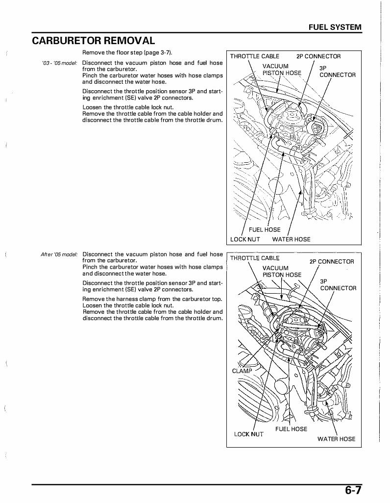
CARBURETOR REMOVAL Remove the floor step {page 3-7).
THROTILE CABLE 2P CONNECTOR '03 � '05 model: Disconnect the vacuum piston hose and fuel hose
from the carbu retor. Pinch the carburetor water hoses with hose clamps and disconnect the water hose.
Disconnect the throttle position sensor 3P and starting enrichment (SE) valve 2P connectors.
Loosen the throttle cable lock nut. Remove the throttle cable from the cable holder and disconnect the throttle cable from the throttle drum.
FUEL HOSE
LOCK NUT WATER HOSE
3P CONNECTOR
Affer '05 model: Disconnect the vacuum piston hose and fuel hose r-T_H
_R_O_TI_L
_E
_C_A_B_L_E--------------,
from the carburetor. 2P CONNECTOR Pinch the carburetor water hoses with hose clamps VACUUM and disconnect the water hose. PISTON HOSE Disconnect the throttle position sensor 3P and starting enrichment (SE) valve 2P connectors.
Remove the harness clamp from the carburetor top. Loosen the throttle cable lock nut. Remove the throttle cable from the cable holder and disconnect the throttle cable from the throttle drum.
FUEL HOSE
3P CONNECTOR
WATER HOSE
6-7
FUEL SYSTEM
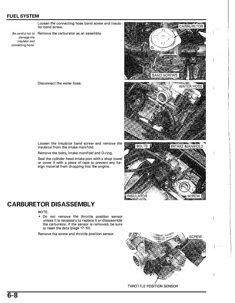
Loosen the connecting hose band screw and insulator band screw.
Be careful not to Remove the carburetor as an assembly. damage the
insulator and connecting hose.
Disconnect the water hose.
Loosen the insulator band screw and remove the insulator from the intake manifold.
Remove the bolts, intake manifold and D-ring.
Seal the cylinder head intake port with a shop towel or cover it with a piece of tape to prevent any foreign material from dropping into the engine.
CARBURETOR DISASSEMBLY
6-8
NOTE: • Do not remove the throttle position sensor
unless it is necessary to replace it or disassemble the carburetor. If the sensor is removed, be sure to reset the data (page 17-10).
Remove the screw and throttle position sensor.
THROTTLE POSITION SENSOR

STARTING ENRICHMENT (SE) VALVE
Remove the SE valve cover, screw, set plate and SE valve.
FUEL SYSTEM
COVER
SE VALVE
Inspect the SE valve and needle for stepped wear or damage. VALVE
VACUUM CHAMBER The vacuum Remove the screws while holding the vacuum
chamber cover is chamber cover. under spring Remove the harness clamp stay (After '05 model
pressure. only).
Remove the vacuum chamber cover, spring and diaphragm/vacuum piston assembly.
Check the piston for smooth operation up and down in the carburetor body.
r�· '\ . '.·'"
/""· o;,�.\�\. .
. . j �tiff':? �.::<�3-::\tff
(>
NEEDLE
VACUUM CHAMBER COVER
SPRING
6-9
FUEL SYSTEM
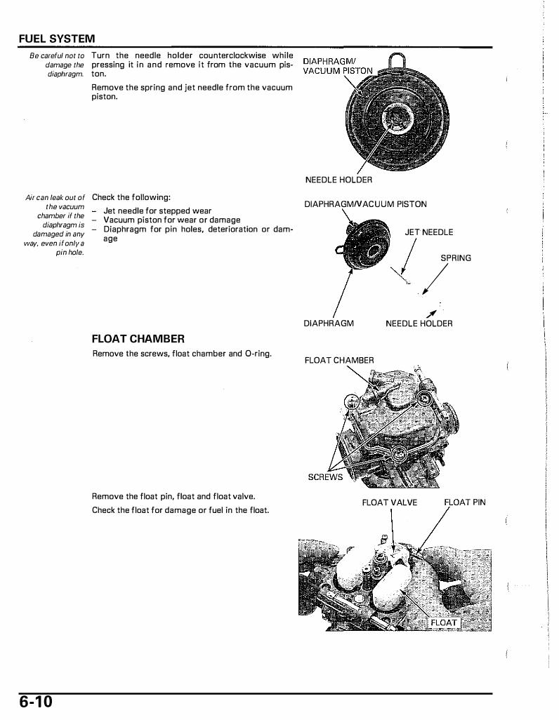
Be careful nat to Turn the needle holder counterclockwise while damage the pressing it in and remove it from the vacuum pisdiaphragm. ton.
Remove the spring and jet needle from the vacuum piston.
Air can leak out of Check the following: the vacuum
chamber if the diaphragm is
damaged in any way, even if only a
pin hole.
6-1 0
Jet needle for stepped wear - Vacuum piston for wear or damage - Diaphragm for pin holes, deterioration or dam-
age
FLOAT CHAMBER
Remove the screws, float chamber and 0-ring.
Remove the float pin, float and float valve.
Check the float for damage or fuel in the float.
NEEDLE HOLDER
DIAPHRAGMNACUUM PISTON
DIAPHRAGM
FLOAT CHAMBER
JET NEEDLE I SPRING '( / /
NEEDLE HOLDER
FLOAT VALVE T PIN
Handle the jets with care. They can
easily be scored or scratched.
Damage to the pilot screw seat will
occur if the pilot screw is tightened
against the seat.
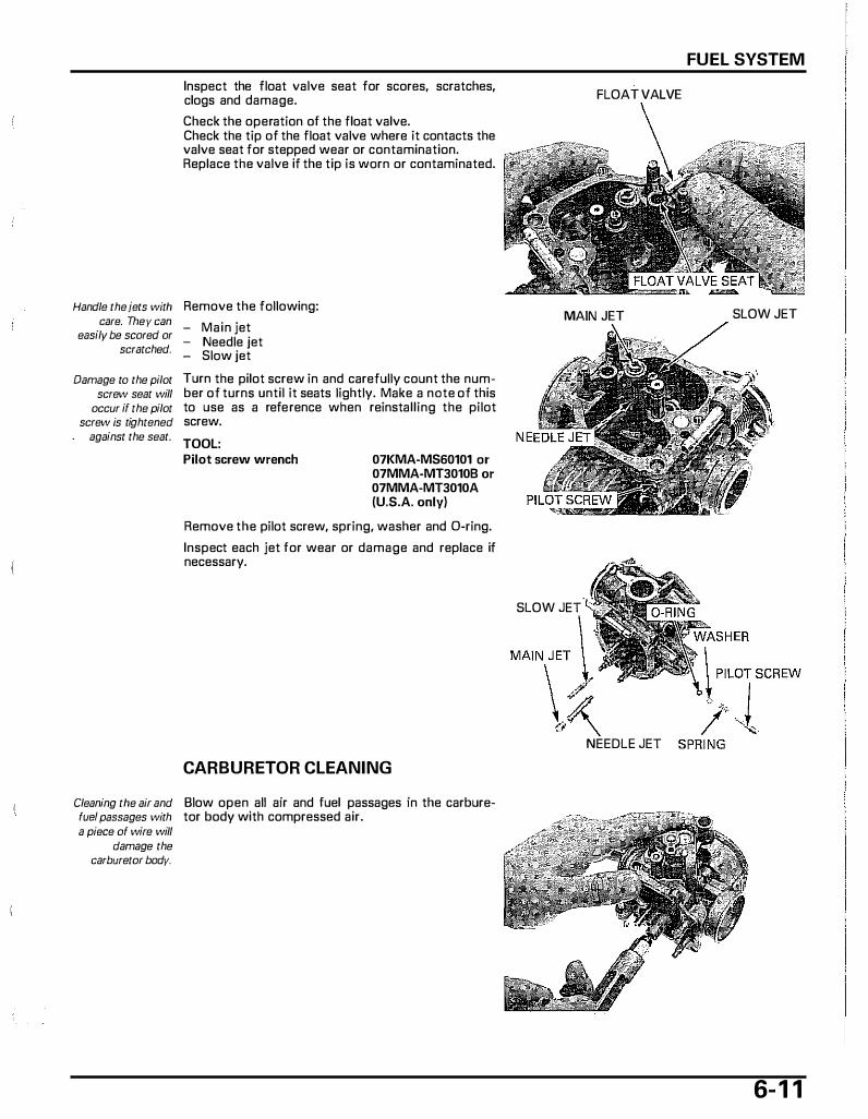
Inspect the float valve seat for scores, scratches, clogs and damage.
Check the operation of the float valve. Check the tip of the float valve where it contacts the valve seat for stepped wear or contamination. Replace the valve if the tip is warn or contaminated.
Remove the fallowing:
- Main jet - Needle jet - Slaw jet
Turn the pilot screw in and carefully count the number of turns until it seats lightly. Make a nate of this to use as a reference when reinstalling the pilot screw.
TOOL: Pilot screw wrench 07KMA-MS60101 or
07MMA-MT3010B or 07MMA-MT3010A (U.S.A. only)
Remove the pilot screw, spring, washer and D-ring.
Inspect each jet for wear or damage and replace if necessary.
CARBURETOR CLEANING
Cleaning the air and Blow open all air and fuel passages in the carburefue/ passages with tar body with compressed air. a piece of wire will
damage the carburetor body.
FUEL SYSTEM
FLOAT VALVE
MAIN JET SLOW JET
SLOW JET
""' "") \� NEEDLE JET
6- 1 1
FUEL SYSTEM
CARBURETOR ASSEMBLY
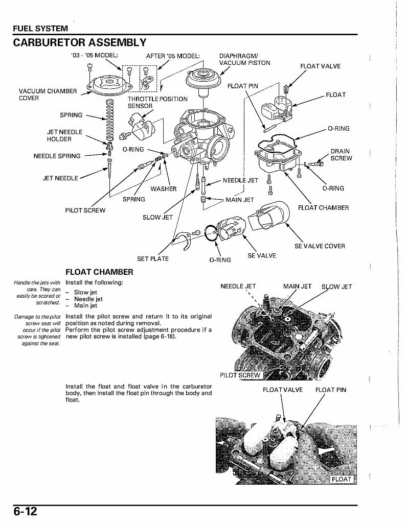
SPRING
JET NEEDLE HOLDER �
NEEDLE SPRING �
JET NEEDLE ---------�
Handle the jets with care. They can
easily be scored or scratched.
PILOT SCREW
FLOAT CHAMBER Install the following:
Slow jet - Needle jet - Main jet
SET PLATE
Damage to the pilot Install the pilot screw and return it to its original screw seat will position as noted during removal.
occur if the pilot Perform the pilot screw adjustment procedure if a screw is tightened new pilot screw is installed (page 6-18).
against the seat.
6- 12
Install the float and float valve i n the carburetor body, then install the float pin through the body and float.
FLOAT VALVE
FLOAT
SE VALVE COVER
NEEDLE JET JET '
'
FLOAT VALVE FLOAT PIN
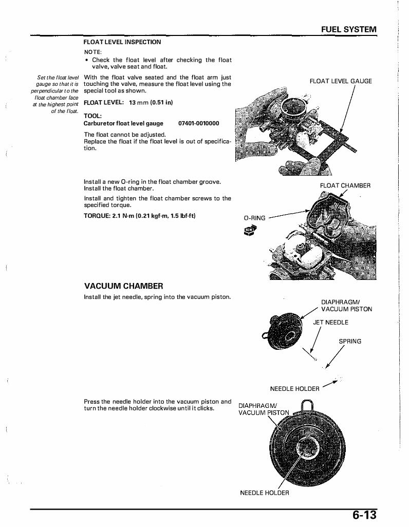
FLOAT LEVEL INSPECTION
NOTE: • Check the float level after checking the float
valve, valve seat and float.
Set the float level With the float valve seated and the float arm just gauge so that it fs touching the valve, measure the float level using the
perpendicular to the special tool as shown. float chamber face
at the highest point FLOAT LEVEL: 13 m m (0.51 in) of the float.
TOOL: Carburetor float level gauge 07401-0010000
The float cannot be adjusted. Replace the float if the float level is aut of specification.
Install a new 0-ring in the float chamber groove. Install the float chamber.
Install and tighten the float chamber screws to the specified torque.
TORQUE: .2.1 N·m (0.21 kgf·m, 1.5 lbf·ft)
VACUUM CHAMBER
Install the jet needle, spring into the vacuum piston.
Press the needle holder into the vacuum piston and turn the needle holder clockwise until it clicks.
D-RING
!$'!" ....
FUEL SYSTEM
FLOAT LEVEL GAUGE
FLOAT CHAMBER
DIAPHRAGM/ VACUU M PISTON
JET NEEDLE I SPRING
"\. / NEEDLE HOLDER ...--'
NEEDLE HOLDER
6-1 3
FUEL SYSTEM
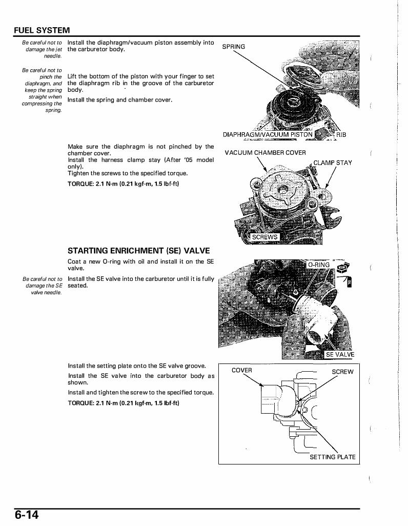
Be careful not to Install the diaphragm/vacuum piston assembly into damage the jet the carburetor body.
needle.
Be careful not to pinch the
diaphragm, and keep the spring
straight when compressing the
spring.
Lift the bottom of the piston with your finger to set the diaphragm rib in the groove of the carburetor body.
Install the spring and chamber cover.
Make sure the diaphragm is not pinched by the chamber cover. Install the harness clamp stay (After '05 model only). Tighten the screws to the specified torque.
TORQUE: 2.1 N·m (0.21 kgf·m, 1.5 lbf.ft)
STARTING ENRICHMENT (SE) VALVE
Coat a new 0-ring with oil and install it on the SE valve.
Be careful not to Install the SE valve into the carburetor until it is fully damage the SE seated.
valve needle.
6-1 4
Install the setting plate onto the SE valve groove.
Install the SE va lve into the carburetor body as shown.
Install and tighten the screw to the specified torque.
TORQUE: 2.1 N·m (0.21 l<gf·m, 1.5 lbf·ft)
SPRING
VACUUM CHAMBER COVER
COVER SCREW
SETTING PLATE

Install the throttle position sensor (page 1 7-9).
CARBURETOR INSTALLATION Coat a new D-ring with oil and i nstall it into the i ntake manifold groove. Install the intake manifold by tightening the bolts.
Install the insulator by aligning the groove of the insulator with the tab of the intake manifold. Tighten the insulator band screw.
Connect the water hose and remove the hose clamp.
FUEL SYSTEM
THROTTLE POSITION SENSOR
6- 1 5

FUEL SYSTEM
Install the carburetor body between the insulator and connecting hose.
Align the tab of the carburetor with the tab of the insulator.
'03 - '05 model: Tighten the band screws securely.
5 ± 1 mm (0.2 ± 0.04 in)
After '05 model: Tighten the band screws to the specified torque.
TORQUE: 3.0 N·m (0.30 kgf·m, 2.2 lbf.ft)
'03 · '05model: Connect the throttle cable to the throttle drum and ,-------------------., install it to the cable holder. THROTILE CABLE 2P CONNECTOR
6-1 6
Loosely tighten the throttle cable adjusting nut. 3P
Connect the throttle position sensor 3P connector and starting enrichment (SE) valve 2P connector.
Connect the fuel hose, vacuum piston hose and water hose to the carburetor. Remove the hose clamp.
After installing the carburetor, check for the following:
- Coolant level (page 4-13) - Engine idle speed (page 4-1 2) - Throttle grip free play (page 4-4)
If the throttle position sensor is removed, be sure to reset the data (page 17-10).
Install the floor step (page 3-7).
CONNECTOR
FUEL HOSE
LOCK NUT WATER HOSE
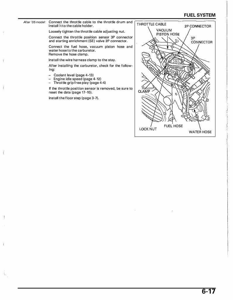
After '05 model: Connect the throttle cable to the throttle drum and i nstall it to the cable holder.
Loosely tighten the throttle cable adjusting nut.
Connect the throttle position sensor 3P connector and starting enrichment (SE) valve 2P connector.
Connect the fuel hose, vacuum piston hose and water hose to the carburetor. Remove the hose clamp.
Install the wire harness clamp to the stay.
After installing the carburetor, check for the following:
- Coolant level (page 4-13) - Engine idle speed (page 4-12) - Throttle grip free play (page 4-4)
If the throttle position sensor is removed, be sure to reset the data (page 17-10).
Install the floor step (page 3-7).
FUEL SYSTEM
THROTTLE CABLE 2P CONNECTOR
FUEL HOSE
WATER HOSE
6-1 7
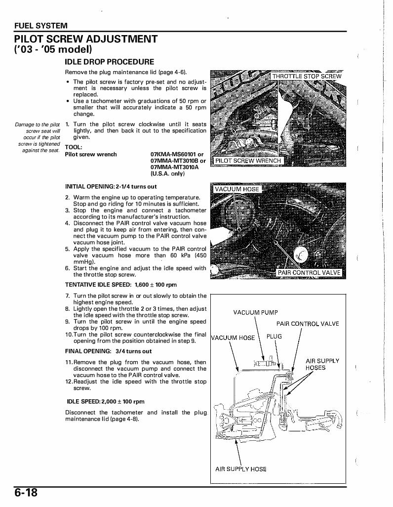
FUEL SYSTEM
PILOT SCREW ADJUSTMENT ('03 - '05 model)
Damage to the pilot screw seat will
occur if the pilot screw is tightened
against the seat.
6- 1 8
IDLE DROP PROCEDURE
Remove the plug maintenance lid (page 4-6).
• The pilot screw is factory pre-set and no adjustment is necessary unless the pilot screw is replaced.
• Use a tachometer with graduations of 50 rpm or smaller that will accurately indicate a 50 rpm change.
1. Turn the pilot screw clockwise until it seats lightly, and then back it out to the specification given.
TOOL: Pilot screw wrench 071<MA-MS60101 or
07MMA-MT3010B or 07MMA-MT3010A (U.S.A. only)
INITIAL OPENING: 2-1/4 turns out
2. Warm the engine up to operating temperature. Stop and go riding for 1 0 minutes is sufficient.
3. Stop the engine and connect a tachometer according to its manufacturer's instruction.
4. Disconnect the PAIR control valve vacuum hose and plug it to keep air from entering, then connect the vacuum pump to the PAIR control valve vacuum hose joint.
5. Apply the specified vacuum to the PAIR control valve vacuum hose more than 60 kPa (450 mmHg).
6. Start the engine and adjust the idle speed with the throttle stop screw.
TENTATIVE IDLE SPEED: 1,600 ± 100 rpm
7. Turn the pilot screw in or out slowly to obtain the highest engine speed.
B. Lightly open the throttle 2 or 3 times, then adjust the idle speed with the throttle stop screw.
9. Turn the pilot screw in until the engine speed drops by 1 00 rpm.
1 0.Turn the pilot screw counterclockwise the final opening from the position obtained in step 9.
FINAL OPENING: 3/4 turns out
1 1 . Remove the plug from the vacuum hose, then disconnect the vacuum pump and connect the vacuum hose to the PAIR control valve.
12. Readjust the idle speed with the throttle stop screw.
IDLE SPEED: 2,000 ± 100 rpm
Disconnect the tachometer and install the plug. maintenance l id (page 4-8).

PILOT SCREW ADJUSTMENT (After '05 model)
Damage to the pilot screw seat will
occur if the pilot screw is tightened
against the seat.
IDLE DROP PROCEDURE
Remove the plug maintenance lid (page 4-6).
• The pilot screw is factory pre-set and no adjustment is necessary unless the pilot screw is replaced.
• Use a tachometer with graduations of 50 rpm or smaller that will accurately indicate a 50 rpm change.
1. Turn the pilot screw clockwise until it seats lightly, and then back it out to the specification given.
TOOL: Pilot screw wrench 07l<MA-MS60101 or
07MMA-MT3010B or 07MMA-MT3010A (U.S.A. only)
INITIAL OPENING:2-1/4 turns out
2. Warm the engine up to operating temperature. Stop and go riding for 1 0 minutes is sufficient.
3. Stop the engine and connect a tachometer according to its manufacturer's instruction.
4. Start the engine and adjust the idle speed with the throttle stop screw.
TENTATIVE IDLE SPEED: 1,600 ± 100 rpm
5. Turn the pilot screw in or out slowly to obtain the highest engine speed.
6. Lightly open the throttle 2 or 3 times, then adjust the idle speed with the throttle stop screw.
7. Turn the pilot screw in until the engine speed drops by 100 rpm.
8. Turn the pilot screw counterclockwise to final opening from the position obtained in step 7.
FINAL OPENING: 3/4 turns out
9. Readjust the idle speed with the throttle stop screw.
IDLE SPEED:2,000 ± 100 rpm
Disconnect the tachometer and install the plug maintenance lid (page 4-8).
�; •
' '
' '
' '
' '
' '
FUEL SYSTEM
6- 1 9

FUEL SYSTEM
HIGH ALTITUDE ADJUSTMENT (After '05 model)
This adjustment must be made at
high altitude to ensure proper high altitude operation.
When the vehicle is to be operated continuously above 2,000 m (6,500 feet), the carburetor must be readjusted as described below to improve driveability and decrease exhaust emissions.
Replace the standard main jet with the high altitude type.
HIGH ALTITUDE MAIN JET: #72
Warm up the engine to operating temperature. Ride the scooter for approximately 10 minutes.
TOOL: Pilot screw wrench 07KMA-MS60101 or
07MMA-MT3010B or 07MMA-MT3010A (U.S.A. only)
HIGH ALTITUDE PILOT SCREW OPENING: 1/4 tum in from the factory preset position
Adjust the idle speed with the throttle stop screw.
IDLE SPEED: 2,000 ± 100 rpm
Do not attach the Attach the Vehicle Emission Control Information label to any part Update Label on the left side of the rear frame as
that can be easily shown. removed from the See Service Letter No. 1 32 for information on
vehicle. obtaining the label.
6-20
I NOTICE I Sustained operation at an altitude lower than 1,500 m (5,000 feet) with the carburetor adjusted for high altitude settings may cause the engine to idle roughly and stall in traffic. It may also cause engine damage due to overheating.
r;:·. · /
' \
\ \
\ \
\
MAIN JET
\ \
UPDATE LABEL
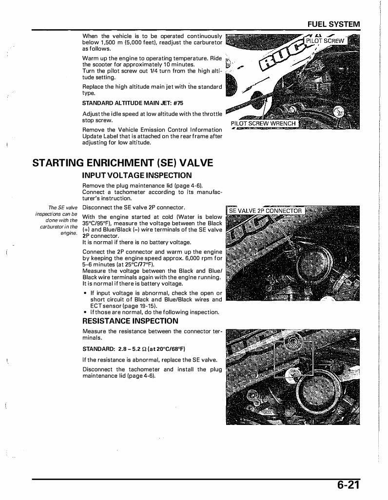
When the vehicle is to be operated continuously below 1 ,500 m (5,000 feet), readjust the carburetor as follows.
Warm up the engine to operating temperature. Ride � the scooter for approximately 1 0 minutes. fd·' - / Turn the pilot screw out 1/4 turn from the high altitude setting.
Replace the high altitude main jet with the standard type.
STANDARD ALTITUDE MAIN JET: #75
Adjust the idle speed at low altitude with the throttle stop screw.
Remove the Vehicle Emission Control I nformation Update Label that is attached on the rear frame after adjusting for low altitude.
STARTING ENRICHMENT (SE) VALVE
INPUT VOLTAGE INSPECTION
Remove the plug maintenance lid (page 4-6). Connect a tachometer according to its manufacturer's instruction.
The SE valve Disconnect the SE valve 2P connector. inspectfons can be
dane with the carburetor in the
engine.
With the engine started at cold (Water is below 35"C/95"F), measure the voltage between the Black (+) and Blue/Black (-) wire terminals of the SE valve 2P connector. It is normal if there is no battery voltage.
Connect the 2P connector and warm up the engine by keeping the engine speed approx. 6,000 rpm for 5-6 minutes (at 25"Cn7"F). Measure the voltage between the Black and Blue/ Black wire terminals again with the engine running. It is normal if there is battery voltage.
• If input voltage is abnormal, check the open or short circuit of Black and Blue/Black wires and ECT sensor (page 19-15).
• If those are normal, do the following inspection.
RESISTANCE INSPECTION
Measure the resistance between the connector terminals.
STANDARD: 2.8 - 5.2 Q (at 20"C/68"F)
If the resistance is abnormal, replace the SE valve.
Disconnect the tachometer and install the plug maintenance lid (page 4-6).
FUEL SYSTEM
6-21
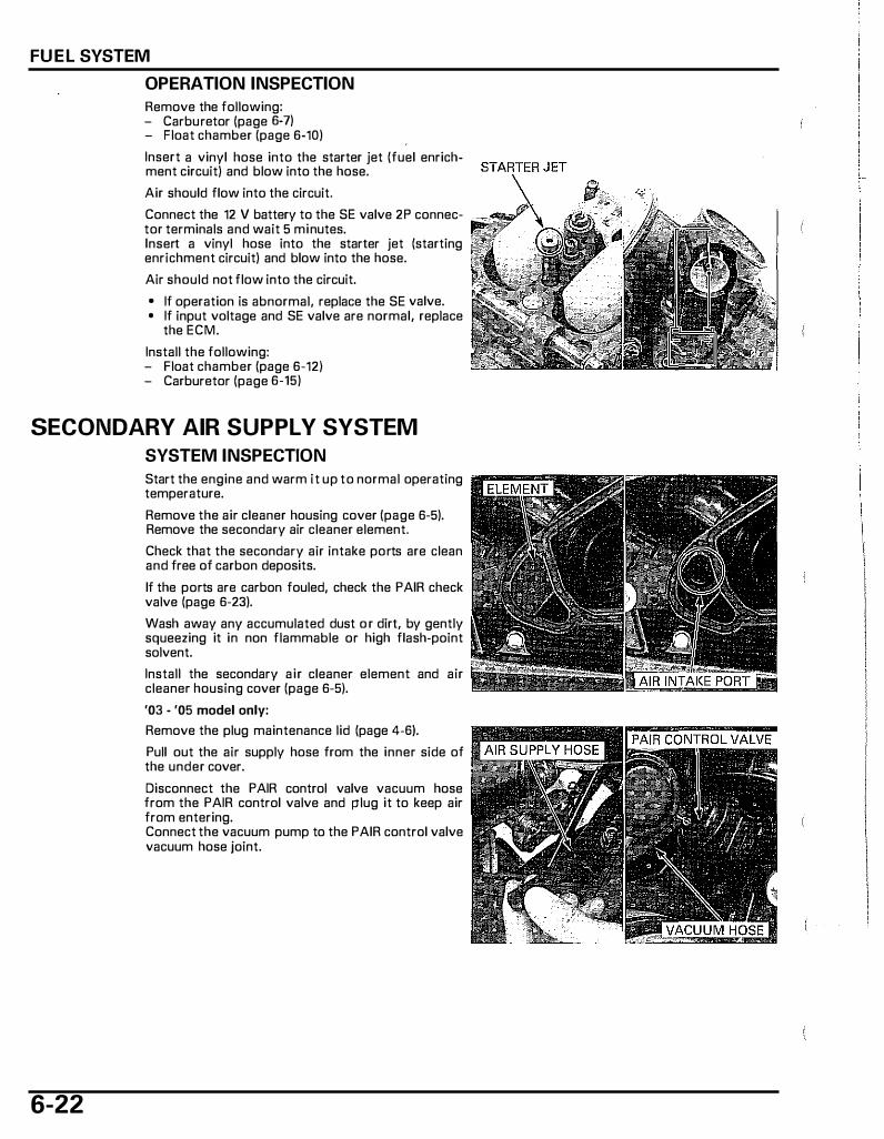
FUEL SYSTEM
OPERATION INSPECTION
Remove the following: - Carburetor (page 6-7) - Float chamber (page 6-10)
Insert a vinyl hose into the starter jet (fuel enrichment circuit) and blow into the hose.
Air should flow into the circuit.
Connect the 12 V battery to the SE valve 2P connector terminals and wait 5 minutes. Insert a vinyl hose into the starter jet (starting enrichment circuit) and blow into the hose.
Air should not flow into the circuit.
• If operation is abnormal, replace the SE valve. • If input voltage and SE valve are normal, replace
the ECM.
Install the following: - Float chamber (page 6-12) - Carburetor (page 6-15)
SECONDARY AIR SUPPLY SYSTEM
SYSTEM INSPECTION
6-22
Start the engine and warm it up to normal operating temperature.
Remove the air cleaner housing cover (page 6-5). Remove the secondary air cleaner element.
Check that the secondary air intake ports are clean and free of carbon deposits.
If the ports are carbon fouled, check the PAIR check valve (page 6-23).
Wash away any accumulated dust o r dirt, by gently squeezing it in non flammable or high flash�point solvent.
Install the secondary air cleaner element and air cleaner housing cover (page 6-5).
'03 - '05 model only:
Remove the plug maintenance lid (page 4-6).
Pull out the air supply hose from the inner side of the under cover.
Disconnect the PAIR control valve vacuum hose from the PAIR control valve and plug it to keep air from entering. Connect the vacuum pump to the PAIR control valve vacuum hose joint.
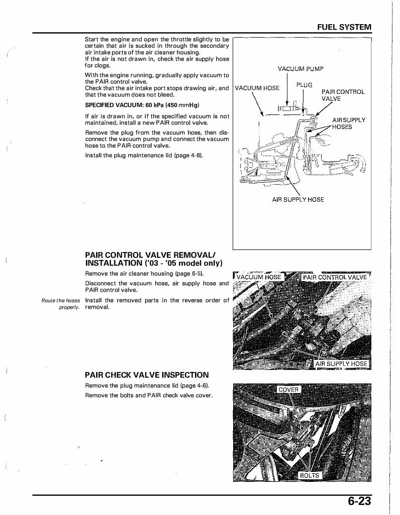
Start the engine and open the throttle slightly to be certain that air is sucked in through the secondary air intake ports of the air cleaner housing. If the air is not drawn in, check the air supply hose for clogs.
With the engine running, gradually apply vacuum to the PAIR control valve. Check that the air intake port stops drawing air, and that the vacuum does not bleed.
·
SPECIFIED VACUUM: 60 kPa (450 mmHg)
If air is drawn in, or if the specified vacuum is not maintained, install a new PAIR control valve.
Remove the plug from the vacuum hose, then disconnect the vacuum pump and connect the vacuum hose to the PAIR control valve.
Install the plug maintenance lid (page 4-8).
PAIR CONTROL VALVE REMOVAL! INSTALLATION ('03 - '05 model only)
Remove the air cleaner housing (page 6-5).
Disconnect the vacuum hose, air supply hose and PAIR control valve.
Route the hoses Install the removed parts in the reverse order of property. removal.
PAIR CHECK VALVE INSPECTION
Remove the plug maintenance lid (page 4-6).
Remove the bolts and PAIR checlc valve cover.
FUEL SYSTEM
6-23
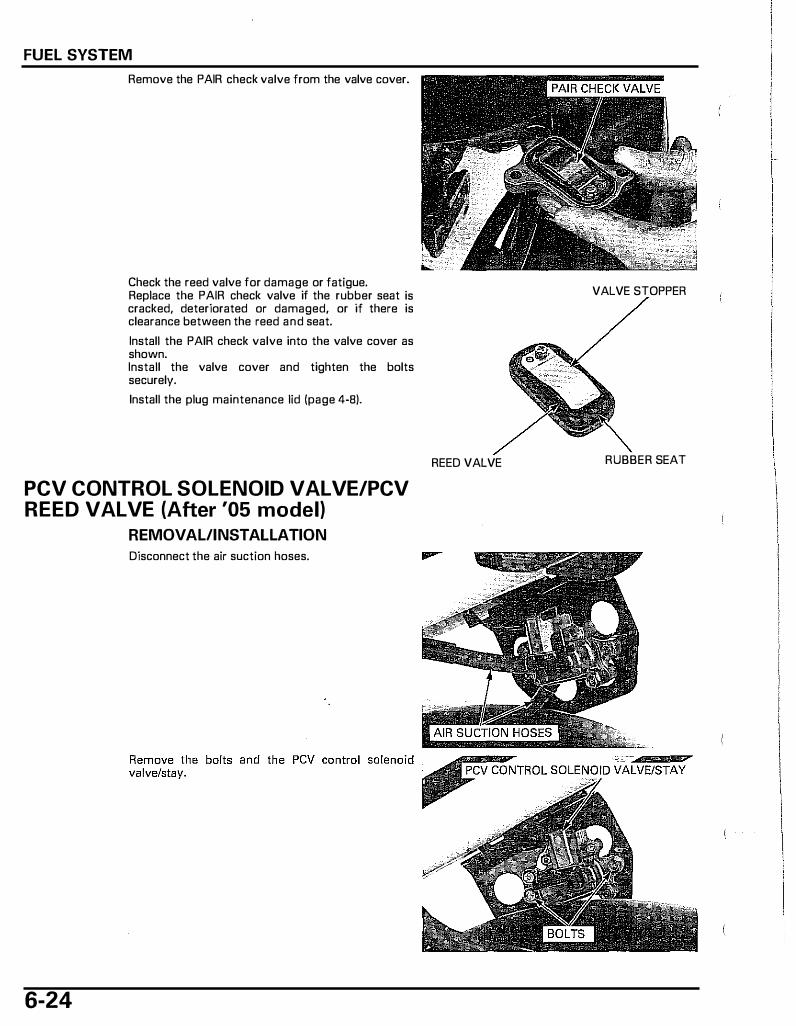
FUEL SYSTEM
Remove the PAIR check valve from the valve cover.
Check the reed valve for damage or fatigue. Replace the PAIR check valve if the rubber seat is cracked, deteriorated or damaged, or if there is clearance between the reed and seat.
Install the PAIR check valve into the valve cover as shown. Install the valve cover and tighten the bolts securely.
Install the plug maintenance lid (page 4-B).
PCV CONTROL SOLENOID VALVE/PCV REED VALVE (After '05 model)
REMOVAL/INSTALLATION
Disconnect the air suction hoses.
6-24
VALVE STOPPER
REED VALVE RUBBER SEAT

Disconnect the PCV control solenoid valve 2P con- �- -
nectar. 2P
Remove the bolts and PCV solenoid valve from the PCV reed valve case.
Remove the 0-ring from the solenoid valve.
Remove the bolts and cover from the case.
COVER
FUEL SYSTEM
-PCV CONTROL SOLENOID VALVE
BOLTS
CASE
BOLTS
Remove the PCV reed valve from the case.
Install the PCV reed valve to the case securely. PCV REED VALVE
CASE
6-25
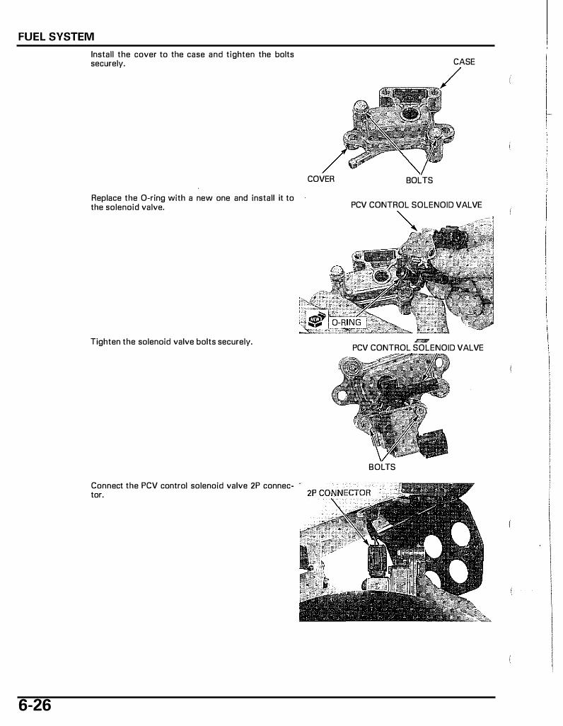
FUEL SYSTEM
6-26
Install the cover to the case and tighten the bolts securely.
Replace the 0-ring with a new one and install it to the solenoid valve.
Tighten the solenoid valve bolts securely.
Connect the PCV control solenoid valve 2P connector.
COVER
CASE
BOLTS
PCV CONTROL SOLENOID VALVE
4mU PCV CONTROL SOLENOID VALVE
BOLTS
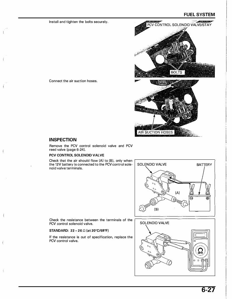
Install and tighten the bolts securely.
Connect the air suction hoses.
INSPECTION
Remove the PCV control solenoid valve and PCV reed valve (page 6-24).
PCV CONTROL SOLENOID VALVE
Check that the air should flow (AI to (B), only when the 12V battery is connected to the PCV control solenoid valve terminals.
FUEL SYSTEM
SOLENOID VALVE/STAY
SOLENOID VALVE BATTERY """
Check the resistance between the terminals of the �===============� PCV control solenoid valve.
STANDARD: 22 - 26 l1 (at 20"C/6B"F)
lf the resistance is out of specification, replace the PCV control valve.
SOLENOID VALVE
6-27

FUEL SYSTEM
PCV REED VALVE
Check the followings:
- PCV reed valve for wear or damage - Valve seat for wear or damage - Valve stopper for damage
Check the no clearance between the PCV reed valve and valve seat.
Replace the PCV reed valve as an assembly, if necessary.
FUEL TANK
REMOVAL/INSTALLATION
6-28
Remove the floor step (page 3-7).
Disconnect the fuel reserve sensor 3P connector.
Lift the fuel tank and pinch the fuel hose.
Disconnect the fuel hose from the fuel filter and remove the fuel tank.
VALVE STOPPER
RUBBER SEAT PCV REED VALVE
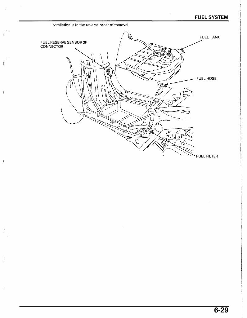
FUEL RESERVE SENSOR 3P CONNECTOR
FUEL SYSTEM
FUEL TANK
FUEL HOSE
FUEL FILTER
6-29

7. COOLI NG SYSTEM
SYSTEM FLOW PATTERN . . . . . . . . . . . . . . . . . . . . . . . . . . . . 7-2 COOLANT REPLACEMENT · · · · · · · · · · · · · · · · · · · · · · · · · · · ·7-6 .. SERVICE INFORMATION · · · · · · · · · · · · · · · · · · · · · · · · · · · · · · 7-3
TROUBLESHOOTING · · · · · · · · · · · · · · · · · · · · · · · · · · · · · · · · · · · · 7-4 I WATER PUMP/THERMOSTAT · · · · · · · · · · · · · · · · · · · · · ·7-8
RADIATOR · · · · · · · · · · · · · · · · · · · · · · · · · · · · · · · · · · · · · · · · · · · · · · · · · · · ·7-12
COOLANT SYSTEM TESTING · · · ·· · · · · · · · · · · · · · · · · · 7-5 RADIATOR RESERVE TANK · · · · · · · · · · · · · · · · · · · · · · · ·7-14
7-1
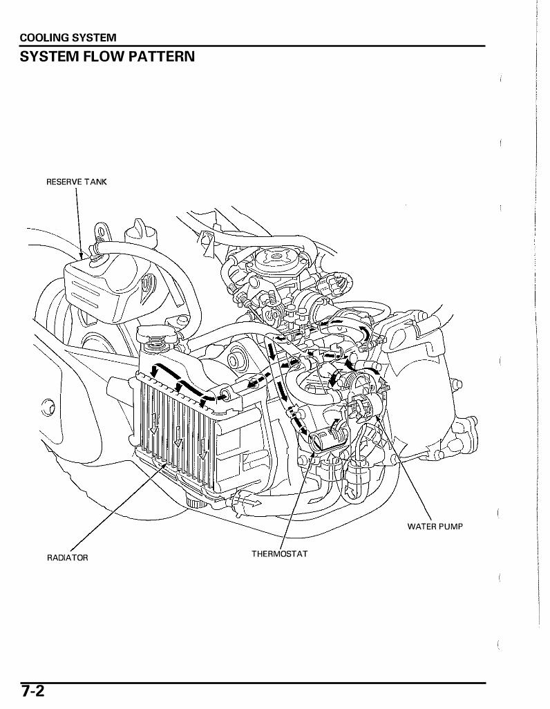
COOLING SYSTEM
SYSTEM FLOW PATTERN
RESERVE TANK
WATER PUMP
RADIATOR THERMOSTAT
7-2

COOLING SYSTEM
SERVICE INFORMATION
GENERAL
Removing the radiator cap while the engine is hot can allow the coolant to spray out, seriously scalding you. Always let the engine and radiator cool down before removing the radiator cap.
I NOTICE I Using coolant with silicate corrosion inhibitors may cause premature wear of water pump seals or blockage of radiator passages. Using tap water may cause engine damage.
• Add coolant at the reserve tank. Do not remove the radiator cap except to refill or drain the system. • All cooling system services can be done with the engine in the frame. • Avoid spilling coolant on painted surfaces. • After servicing the system, check for leaks with a cooling system tester. • When the coolant temperature exceeds 120 oc (248 °F), the coolant temperature indicator will blink. The ECM will then
control the ignition and reduce engine speed to 9 mph ( 1 5 km/h). At this time, check the cooling system and engine for leaks or damage. If everything is OK, then check the coolant indicator circuit and thermosensor (page 1 9-15).
• This scooter features a magnetic-coupling water pump.
SPECIFICATIONS
ITEM Coolant capacity
Radiator cap relief pressure Thermostat
Standard coolant concentration
TORQUE VALUES
Radiator drain bolt Radiator cover screw
I I STANDARD
Radiator and engine 0.48 liter (0.51 US qt, 0.42 Imp qt) Reserve tank 0.28 liter (0.30 US qt, 0.25 Imp qt)
108 - 1 37 kPa (1.1 - 1.4 kgf/cm2, 1 6 - 20 psi) Begin to open Fully open Valve lift
1.0 N·m (0.1 kgf·m, 0.7 lbf·ft) 1.0 N·m (0.1 kgf·m, 0.7 lbf·ft)
74 78 "C (165 172 °F) 100 "C (212 °F)
8 mm (0.3 in) minimum 1:1 mixture with soft water
7-3
COOLING SYSTEM
TROUBLESHOOTING Engine temperature too high • Thermostat stuck closed • Faulty radiator cap • Insufficient coolant • Passage blocked in radiator, hoses or water jacket • Air in system • Faulty water pump • Faulty ECT sensor
Engine temperature too low • Faulty ECT sensor • Thermostat stuck open
Coolant leak • Deteriorated O�rings • Faulty radiator cap • Damaged or deteriorated cylinder head gasket • Loose hose connection or clamp • Damaged or deteriorated hoses
7-4
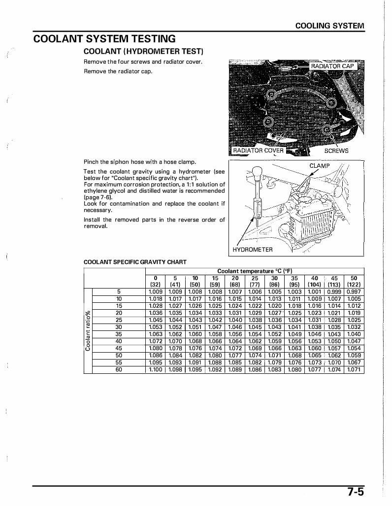
COOLANT SYSTEM TESTING
COOLANT (HYDROMETER TEST)
Remove the four screws and radiator cover.
Remove the radiator cap.
Pinch the siphon hose with a hose clamp.
Test the coolant gravity using a hydrometer (see below for "Coolant specific gravity chart"). For maximum corrosion protection, a 1 : 1 solution of ethylene glycol and distilled water is recommended (page 7-6). Look for contamination and replace the coolant if necessary.
Install the removed parts in the reverse order of removal.
COOLANT SPECIFIC GRAVITY CHART
COOLING SYSTEM
HYDROMETER
Coolant temperature oc (°F) 0 5 10 1 5 20 25 30 35 40 45 50
(32) (41) (50) (59) (68) (77) (86) (95) ( 104) (113) (122) 5 1.009 1.oo9 1 1.008 1.oo8 1 1.001 1.006 1.005 1.003 1.001 0.999 0.997 10 1.018 1.017 1.017 1.016 1.o15 1 1.014 1.013 1.011 1.oos 1 1.001 1.005 1 5 1.028 1.027 1.026 1.025 1.024 1.022 1.020 1.018 1.016 1 1.014 1.012
� 0 20 1.036 1.035 1.034 1.033 1.031 1.029 1.027 " 1.025 1.023 1.021 1.019 .Q 25 1.045 1.044 1.043 1.042 1.040 1.038 1 1.036 1.034 1.031 1.028 1.025 1§ 30 1 1.053 1.052 1 1.051 1.047 1 .046 1.045 1.043 1.041 1.038 1.035 1.032 �
35 1.063 1.062 1.060 1.058 1 1.056 1.054 1.052 1.049 1.046 1.043 1.040 c 3! 0 40 1.072 1.070 1.068 1.066 1.064 1.062 1.059 1.056 1.053 1 1.o5o 1 1.047 0 45 1.080 1.078 1.076 1.074 1.072 1.069 1.066 1.063 1 1.o6o 1.057 1.054 u
50 1.086 1.084 1.082 1.080 1.077 1.074 1 1.011 1.068 1.065 1.062 1.059 55 1.095 1 1.093 1.091 1.088 1.085 1.082 1 1.079 1.076 1.073 1.070 1.067 60 1 1.100 1 1.098 1 1.095 1.092 1 1.089 1.086 I 1.083 1.080 1.077 1.074 1.071
7-5
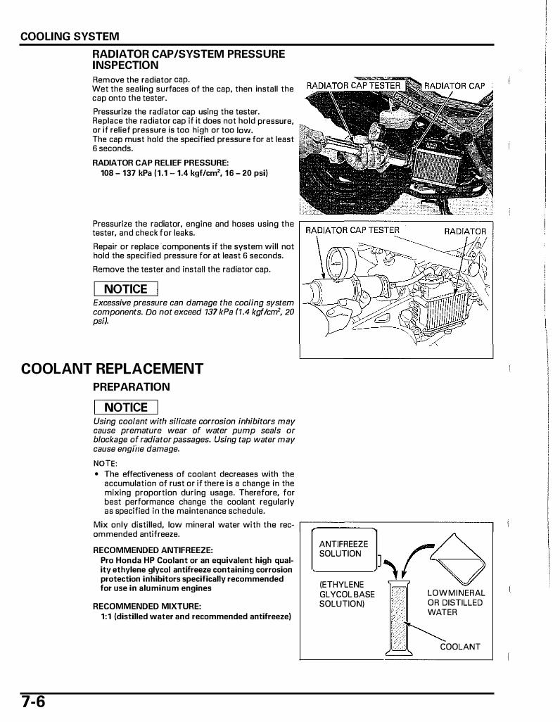
COOLING SYSTEM
RADIATOR CAP/SYSTEM PRESSURE INSPECTION
Remove the radiator cap. Wet the sealing surfaces of the cap, then install the cap onto the tester.
Pressurize the radiator cap using the tester. Replace the radiator cap if it does not hold pressure, or if relief pressure is too high or too low. The cap must hold the specified pressure for at least 6 seconds.
RADIATOR CAP RELIEF PRESSURE: 108 - 137 kPa (1.1 - 1.4 kgf/cm2, 16 - 20 psi)
Pressurize the radiator, engine and hoses using the tester, and check for leaks.
Repair or replace -components if the system will not hold the specified pressure for at least 6 seconds.
Remove the tester and install the radiator cap.
I NOTICE I Excessive pressure can damage the cooling system components. Do not exceed 137 kPa (1.4 kgf!cm', 20 psi).
COOLANT REPLACEMENT
PREPARATION
I NOTICE I Using coolant with silicate corrosion inhibitors may cause premature wear of water pump seals or blockage of radiator passages. Using tap water may cause engi'ne damage.
NOTE: • The effectiveness of coolant decreases with the
accumulation of rust or if there is a change in the mixing proportion during usage. Therefore, for best performance change the coolant regularly as specified in the maintenance schedule.
Mix only distilled, low mineral water with the rec- r---;:::::::::::::::::::::::::::::::::::::::----------� om mended antifreeze.
7-6
RECOMMENDED ANTIFREEZE: Pro Honda HP Coolant or an equivalent high quality ethylene glycol antifreeze containing corrosion protection inhibitors specifically recommended for use in aluminum engines
RECOMMENDED MIXTURE: 1:1 (distilled water and recommended antifreeze)
ANTIFREEZE SOLUTION
(ETHYLENE GLYCOL BASE SOLUTION)
LOW MINERAL OR DISTILLED WATER
COOLANT
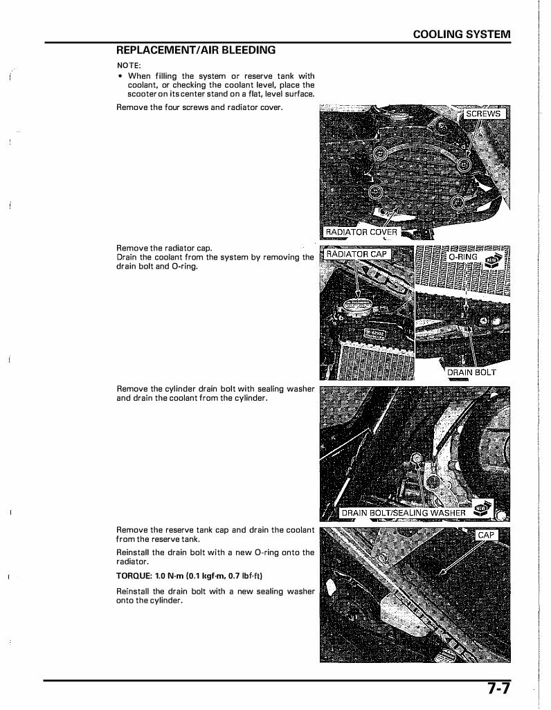
REPLACEMENT I AIR BLEEDING
NOTE: • When filling the system or reserve tank with
coolant, or checking the coolant level, place the scooter on its center stand on a flat, level surface.
Remove the four screws and radiator cover.
Remove the radiator cap. Drain the coolant from the system by removing the drain bolt and 0-ring.
Remove the cylinder drain bolt with sealing washer and drain the coolant from the cylinder.
Remove the reserve tank cap and drain the coolant from the reserve tank.
Reinstall the drain bolt with a new 0-ring onto the radiator.
TORQUE: 1.0 N·m {0.1 1<gf·m, 0.7 lbf.ft)
Reinstall the drain bolt with a new sealing washer onto the cylinder.
COOLING SYSTEM
7-7
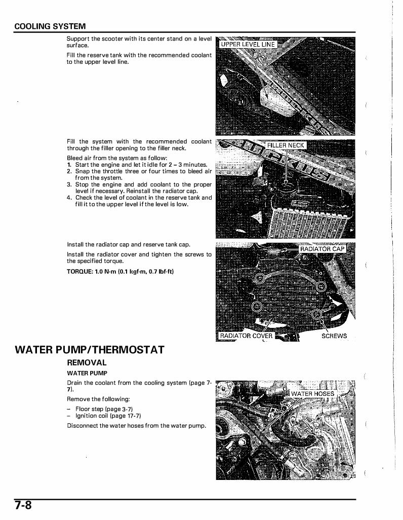
COOLING SYSTEM
Support the scooter with its center stand on a level surface.
Fill the reserve tank with the recommended coolant to the upper level line.
Fill the system with the recommended coolant through the filler opening to the filler neck.
Bleed air from the system as follow: 1. Start the engine and let it idle for 2 - 3 minutes. 2. Snap the throttle three or four times to bleed air
from the system. 3. Stop the engine and add coolant to the proper
level if necessary, Reinstall the radiator cap. 4. Check the level of coolant in the reserve tank and
fill it to the upper level if the level is low.
Install the radiator cap and reserve tank cap.
Install the radiator cover and tighten the screws to the specified torque.
TORQUE: 1.0 N·m (0.1 l<gf·m, 0.7 1bf·ft)
WATER PUMP/THERMOSTAT
REMOVAL
7-8
WATER PUMP
Drain the coolant from the cooling system {page 7-7).
Remove the following:
- Floor step (page 3-7) - Ignition coil (page 17-7)
Disconnect the water hoses from the water pump.
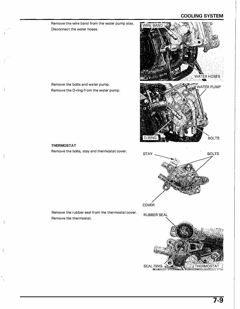
Remove the wire band from the water pump stay.
Disconnect the water hoses.
Remove the bolts and water pump.
Remove the D-ring from the water pump.
THERMOSTAT
Remove the bolts, stay and thermostat cover.
Remove the rubber seal from the thermostat cover.
Remove the thermostat.
COOLING SYSTEM
STAY
COVER
RUBBER SEAL
7-9
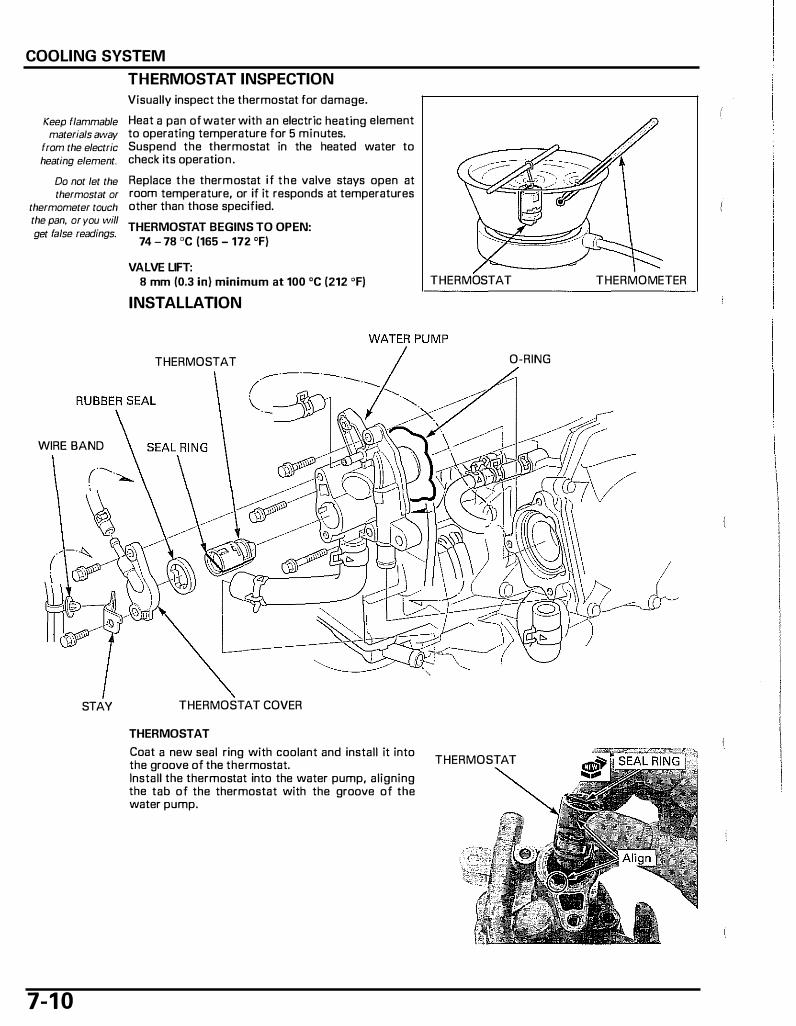
COOLING SYSTEM
Keep flammable materials away
from the electric heating element.
Do not let the thermostat or
thermometer touch the pan, or you will get false readings.
WIRE BAND
STAY
7-1 0
THERMOSTAT INSPECTION
Visually inspect the thermostat for damage.
Heat a pan of water with an electric heating element to operating temperature for 5 minutes. Suspend the thermostat in the heated water to check its operation.
Replace the thermostat if the valve stays open at room temperature, or if it responds at temperatures other than those specified.
THERMOSTAT BEGINS TO OPEN: 74 - 78 "C (165 - 172 "F)
VALVE LIFT: 8 mm (0.3 in) minimum at 100 "C (212 "F)
INSTALLATION
THERMOSTAT
THERMOSTAT COVER
THERMOSTAT
Coat a new seal ring with coolant and install it into the groove of the thermostat. Install the thermostat into the water pump, aligning the tab of the thermostat with the groove of the water pump.
THERMOSTAT THERMOMETER
0-RING
THERMOSTAT

I nstall a new rubber seal i nto the thermostat cover groove. RUBBER SEAL
!$.!, ......
I nstall the thermostat housing cover, stay and tighten the bolts securely. STAY
WATER PUMP
Clean the inside of the outer magnet and the water pump magnet, and check that no nuts or bolts are magnetically attached to the magnet.
Coat a new D-ring with engine oil and install it into the groove of the water pump.
Install the water pump into the cylinder head and tighten the bolts securely.
COVER
COOLING SYSTEM
BOLTS
7- 1 1

COOLING SYSTEM
Connect the water hoses.
Install the wire band onto the stay.
Connect the water hoses.
Install the following:
- Ignition coil (page 17-7) - Floor step (page 3-7)
Fill and bleed the cooling system (page 7-8).
RADIATOR
REMOVAL
Drain the coolant from the cooling system (page 7-7).
Disconnect the siphon hose and water hoses from the radiator.
Remove the rear fender and radiator mounting bolts.
Be careful not to Remove the radiator from the water pipe. damage the radiator fins while servicing
the radiator.
7 - 1 2
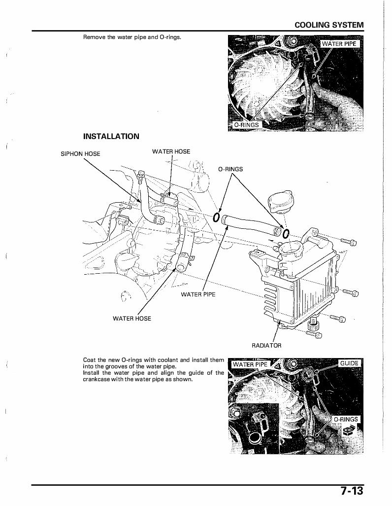
COOLING SYSTEM
Remove the water pipe and 0-rings.
INSTALLATION
SIPHON HOSE WATER HOSE
0-RINGS
WATER HOSE
RADIATOR
Coat the new 0-rings with coolant and install them ll"'���"""""'''l i nto the grooves of the water pipe. Install the water pipe and align the guide of the crankcase with the water pipe as shown.
7-13
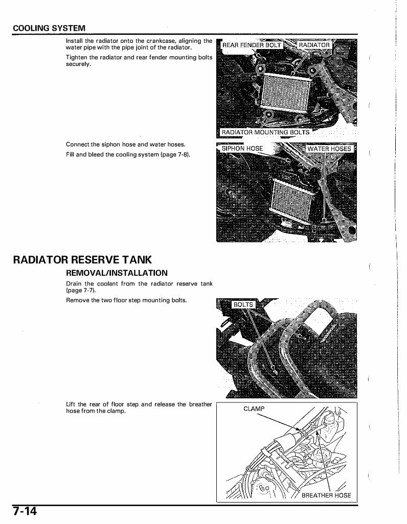
COOLING SYSTEM
Install the radiator onto the crankcase, aligning the water pipe with the pipe joint of the radiator.
Tighten the radiator and rear fender mounting bolts securely.
Connect the siphon hose and water hoses.
Fill and bleed the cooling system (page 7-B).
RADIATOR RESERVE TANK
REMOVAL/INSTALLATION
7-14
Drain the coolant from the radiator reserve tank (page 7-7).
Remove the two floor step mounting bolts.
Lift the rear of floor step and release the breather ,--------------------, hose from the clamp.
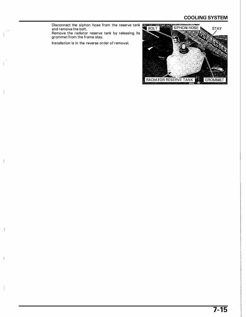
Disconnect the siphon hose from the reserve tank and remove the bolt. Remove the radiator reserve tank by releasing its grommet from the frame stay.
Installation is in the reverse order of removal.
COOLING SYSTEM
7- 1 5

8. ENGINE REMOVAL/INSTALLATION
COMPONENT LOCATIONS······· .................... 8-2
SERVICE INFORMATION ······························ 8-3
ENGINE REMOVAL ········································8-4
ENGINE INSTALLATION································8-7 .. I
8-1
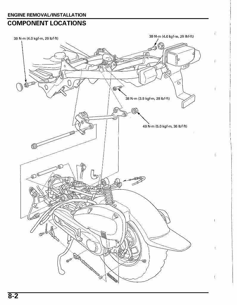
ENGINE REMOVAL/INSTALLATION
COMPONENT LOCATIONS
39 N·m (4.0 kgf·m, 29 lbf.ft)
() 38 N·m (3.9 kgf·m, 28 lbf.ft)
49 N·m (5.0 kgf·m, 36 lbf.ft)
8-2
ENGINE REMOVAL/INSTALLATION
SERVICE INFORMATION
GENERAL • During engine removal and installation, support the scooter using a hoist or equivalent. • Support the engine using a jack or other adjustable support to ease of engine mounting bolt removal. • When removing/installing the engine, tape the frame around the engine beforehand .for frame protection. • The following components require engine removal for service.
- Crankshaft/piston/cylinder (page 1 3-3) • The following components can be serviced with the engine installed in the frame.
- Kick starter/drive pulley/driven pulley/clutch (page 1 0-3) - Final reduction (page 1 1 -3) - Alternator/starter (page 1 2-3) - Cylinder head/valves (page 9-3) - Water pump (page 7-3) - Carburetor (page 6-7) - Oil pump (page 5-4)
SPECIFICATION
ITEM SPECIFICATIONS Engine dry weight 20.8 kg (45.9 lbs) Coolant capacity Radiator and engine 0.48 l iter (0.51 US qt, 0.42 Imp qt) Engine oil capacity At draining
At disassembly
TORQUE VALUES
Engine hanger link bolt (frame side) Engine mounting nut (engine side) Rear shock absorber mounting bolt (upper)
0.6 liter (0.6 US qt, 0.5 Imp qt) 0.7 liter (0.7 US qt, 0.6 Imp qt)
39 N·m (4.0 kgf·m, 29 lbf.ft) 49 N·m (5.0 kgf·m, 36 lbf.ft) 38 N·m (3.9 kgf·m, 28 lbf.ft)
U-nut
8-3
ENGINE REMOVAL/INSTALLATION
ENGINE REMOVAL Remove the floor step (page 3-7).
Drain the engine oil (page 4-11 ). Drain the coolant from the cooling system (page 7-7).
I NOTICE I Install the radiator cover to prevent the radiator fin from damage.
Remove the bolts, clamps and ground wire.
Remove the rear brake arm adjusting nut, joint pin and spring.
Remove the brake cable from the cable holder.
'03 - '05 model: Disconnect the ECT sensor, throttle position sensor 3P and SE valve 2P connectors.
ECTSENSOR CONNECTOR
3P CONNECTOR
2P CONNECTOR
After '05 model: Disconnect the ECT sensor, throttle position sensor ,---3-
P_
C_
O_N_N_E_C_T_O_R-------------,
3P and SE valve 2P connectors. HARNESS CLAMP
Remove the wire harness clamp from the stay.
8-4
ECTSENSOR CONNECTOR 2P CONNECTOR

Disconnect the siphon hose, fuel hose and th rottle cable.
Disconnect the engine breather hose and ignition coil wire connectors. Pull out the air supply hose from the inner side of the under cover.
Place a floor jack or other adjustable support under the frame.
Remove the rear shock absorber upper mounting bolt.
ENGINE REMOVAL/INSTALLATION
AIR SUPPLY HOSE
8-5
ENGINE REMOVAL/INSTALLATION
After '05 model Disconnect the air suction hoses from the PCV con- �
8-6
only: trol solenoid valve.
Remove the engine mounting nut.
Pull out the engine mounting bolt, then remove the engine from the frame.
Move the joint tubes inside and remove the mounting collar from the engine.
Check the bushings for wear, deterioration or damage.
Remove the pivot caps, bolts and engine hanger link.
" PCV CONTROL SOLENOID VALVE
Check the rubber stopper and bushings for damage, wear or deterioration.
ENGINE INSTALLATION NOTE: • Before installing the engine, route the wires,
hoses and cables properly (page 1- 15). • The jack height must be continually adjusted to
relieve stress from the mounting fasteners.
I nstall the engine hanger link, aligning the rubber stopper with the frame.
ENGINE REMOVAL/INSTALLATION
Install and tighten the engine hanger link bolts to ��" =� : =-_ the specified torque.
TORQUE: 39 N·m (4.0 l<gf·m, 29 lbf.ft)
Install the pivot caps.
I nstall the joint tubes and collar as shown.
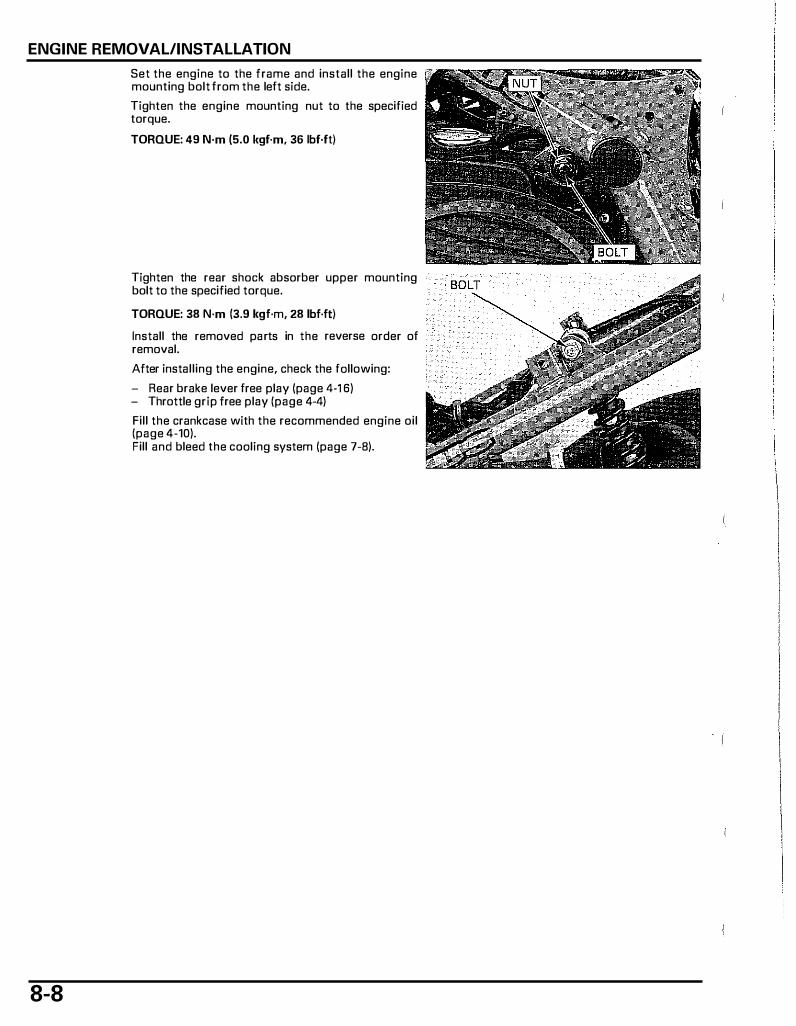
ENGINE REMOVAL/INSTALLATION
8-8
Set the engine to the frame and install the engine mounting bolt from the left side.
Tighten the engine mounting nut to the specified torque.
TORQUE: 49 N·m (5.0 kgf·m, 36 lbf·ft)
Tighten the rear shock absorber upper mounting bolt to the specified torque.
TORQUE: 38 N·m (3.9 l<gf·m, 28 lbf·ft)
Install the removed parts in the reverse order of removal.
After installing the engine, check the fallowing:
- Rear brake lever free play (page 4·1 6) - Throttle grip free play (page 4-4)
Fill the crankcase with the recommended engine oil (page 4-10). Fill and bleed the coaling system (page 7-8).

9. CYLINDER HEAD/VALVES
COMPONENT LOCATIONS·· ......................... 9-2
SERVICE INFORMATION ······························ 9-3
TROUBLESHOOTING···································· 9-5
CYLINDER COMPRESSION TEST················· 9-6
CYLINDER HEAD COVER REMOVAL ··········· 9-6
CAMSHAFT/ROCKER ARMS REMOVAL ····· 9-7
CYLINDER HEAD REMOVAL ······················ 9-10
CYLINDER HEAD DISASSEMBLY ···············9-11
VALVE GUIDE REPLACEMENT ................... 9.13
.. VALVE SEAT INSPECTION/REFACING ······9-14 I I
CYLINDER HEAD ASSEMBLY ·····················9-17
CYLINDER HEAD INSTALLATION···············9-18
CAMSHAFT /ROCKER ARM INSTALLATION·············································9-19
CYLINDER HEAD COVER INSTALLATION·············································9-22
9-1

CYLINDER HEAD/VALVES
COMPONENT LOCATIONS
12 N·m ( 1 .2 kgf·m, 9 1bf.ft)
8.8 N·m (0.9 kgf·m, 6.5 lbf.ft)
9-2
1 0 N·m ( 1 .0 kgf·m, 7 1bf.ft)
AFTER '05 MODEL:
4.2 N·m (0.43 kgf·m, 3.1 lbf.ft)
!1:::0 .
. .
. .
. .
. .
.
.
. .
. .
, _ _ _ _ _ .. .. .. .. .. . .. .. .. .. .. .. .. .. .. :
'03 - '05 MODEL: r-- -.. .. .. .. .. .. .. .. .
.. .. ..
'03 - '05 MODEL:
. . .
. . .
. .
• .
. .
. .
. .
. . .

CYLINDER HEAD/VALVES
SERVICE INFORMATION
GENERAL • This section covers service of the cylinder head, valves, rocker arms and camshaft. • The cylinder head and valves can be serviced with the engine installed in the frame. • When disassembling, mark and store the disassembled parts to ensure that they are reinstalled in their original loca
tions. • Clean all disassembled parts with cleaning solvent and dry them by blowing them off with compressed air before
i nspection. • Camshaft and rocker arm lu bricating oil is fed through oil passages in the cylinder head. Clean the oil passages before
assembling the cylinder head. • Be careful not to damage the mating surfaces when removing the cylinder head cover and cylinder head.
SPECIFICATIONS Unit· mm (in)
ITEM STANDARD SERVICE LIMIT Cylinder compression 1 ,393 kPa (14.2 kgf/cm', 202 psi)
at 1 ,500 rpm Cylinder head warpage 0.05 (0.002) Valve, valve Valve clearance IN I 0.10 ± 0.03 (0.004 ± 0.001) -guide EX 0.19 ± 0.03 (0.007 ± 0.001 )
Valve stem O.D. IN 4.475 - 4.490 (0.1762 - 0.1768) 4.465 (0.1758) EX 4.465 4.480 (0.1758 0.1764) 4.455 (0.1754)
Valve guide I.D. I I N/EX 4.500 - 4.512 (0.1772 - 0.1776) 4.54 (0.179) Stem-to-guide I N 0.010 0.037 (0.0004 0.0015) 0.075 (0.0030) clearance EX 0.020 - 0.047 (0.0008 - 0.0019) 0.085 (0.0033) Valve guide projection IN 9.05 9.35 (0.356 0.368) above cylinder head EX 9.05 - 9.35 (0.356 - 0.368) -Valve seat width I N/EX I 1.0 (0.04) 1.5 (0.06)
Valve spring free length IN/EX 33.5 (1.32) 32.2 ( 1.27) Rocker arm Rocker arm l.D. IN/EX 10.000 - 10.015 (0.3937 - 0.3943) 10.10 (0.400)
Rocker arm shaft O.D. I IN/EX 9.972 - 9.987 (0.3926 0.3932) 9.91 (0.390) Side spring free length 1 6.0 (0.63) 14.5 (0.57)
Camshaft Cam lobe height I IN 29.2365 29.3165 ( 1.15104- 1.15419) 29.2065 (1.14986)
I EX 29.2907 - 29.3707 (1.15318 - 1. 1 5633) 29.2607 (1.15199)
TORQUE VALUES
Cylinder head bolt Cam sprocket bolt
1 2 N·m (1.2 kgf·m, 9 lbf·ft) 8.8 N·m (0.9 kgf·m, 6.5 lbf·ft) 4.2 N·m (0.43 kgf·m, 3.1 lbf·ft) 12 N·m (1.2 kgf·m, 9 lbf·ft)
Apply oil to the threads and flange surface. Apply oil to the threads and flange surface.
Cam chain tensioner lifter screw Spark plug PCV joint bolt (After '05 model) 10 N·m (1 .0 kgf·m, 7 lbf·ft)
9-3

CYLINDER HEAD/VALVES
TOOLS
Valve spring compressor 07757-0010000
Flat cutter, 22 mm (32" IN) 07780-0012601
or equivalent commercially available in U.S.A.
Interior cutter, 17 mm (60" EX) 07780-0014600
or equivalent commercially available in U.S.A.
Valve guide driver, 4.5 m m 07HMD-ML00101
9-4
Seat cutter, 20.5 mm (45" IN) 07780-0011000
or equivalent commercially available in U.S.A.
Flat cutter, 20 mm (32" EX) 07780-0013200
(9 u o r equivalent commercially available in U.S.A.
Cutter holder, 4.5 m m 07781 -0010600
or equivalent commercially available in U.S.A.
Valve guide reamer, 4.508 mm 07HMH-ML00101
or 07HMH-ML0010B or 07HMH-ML0010A (U.S.A. only)
Seat cutter, 17 mm (45" EX) 07780-0011100
or equivalent commercially available in U.S.A.
Interior cutter, 20.5 mm (60" IN) 07780-0014300
or equivalent commercially available in U.S.A.
Valve spring compressor attachment 07GME-KT70200
Cam chain tensioner stopper 070MG-0010100
or 07AMG-001A100 (U.S.A. only)
CYLINDER HEAD/VALVES
TROU BLESHOOTING • Engine top-end problems usually affect engine performance. These problems can be diagnosed by a compression test
or by tracing engine noises to the top-end with a sounding rod or stethoscope. • If the performance is poor at low speeds, check for white smoke in the engine breather drain hose. If the hose is smoky,
check for a seized piston ring (page 13-8).
Compression too low, hard starting or poor performance at low speed • Valves:
- Incorrect valve clearance - Burned or bent valve - Incorrect valve timing - Broken valve spring - Uneven valve seating
• Cylinder head: - Leaking or damaged head gasket - Warped or cracked cylinder head - Loose spark plug
• Worn cylinder, piston or piston rings (page 1 3-8)
Compression too high, overheating or l<nocking • Excessive carbon build-up on piston head or on combustion chamber
Excessive smoke • Worn valve stem or valve guide • Damaged stem seal • Worn cylinder, piston or piston rings (page 1 3-8)
Excessive noise • Incorrect valve clearance • Sticking valve or broken valve spring • Worn or damaged camshaft • Worn or damaged cam chain • Worn cam sprocket teeth • Worn rocker arm and/or shaft • Worn or damaged cam chain tensioner • Worn cylinder, piston or piston rings (page 1 3-8)
Rough idle • Low cylinder compression • Incorrect carburetor setting {page 6-3)
9-5

CYLINDER HEAD/VALVES
CYLINDER COMPRESSION TEST Warm up the engine to normal operating temperature. Stop the engine and remove the spark plug cap and spark plug (page 4-6).
Connect a compression gauge to the spark plug hole.
To avoid discharging Open the throttle all the way and crank the engine the battery. do not with the kick starter or electric starter u ntil the operate the starter gauge reading stops rising.
motor for more The maximum reading is usually reached within 4 -than 7 seconds. 7 seconds when using electric starter.
COMPRESSION PRESSURE: 1,393 kPa (14.2 kg/em', 202 psi) at 1 ,500 rpm
Low compression can be caused by: - Blown cylinder head gasket - Improper valve adjustment - Valve leakage - Worn piston ring or cylinder
High compression can be caused by: - Carbon deposits in the combustion chamber or
on piston head
CYLINDER HEAD COVER REMOVAL
9-6
Remove the fuel tank (page 6-28).
Disconnect the engine breather and air supply hoses. Remove the bolts and cylinder head cover.
Remove the 0-rings from the cylinder head cover. 0-RINGS
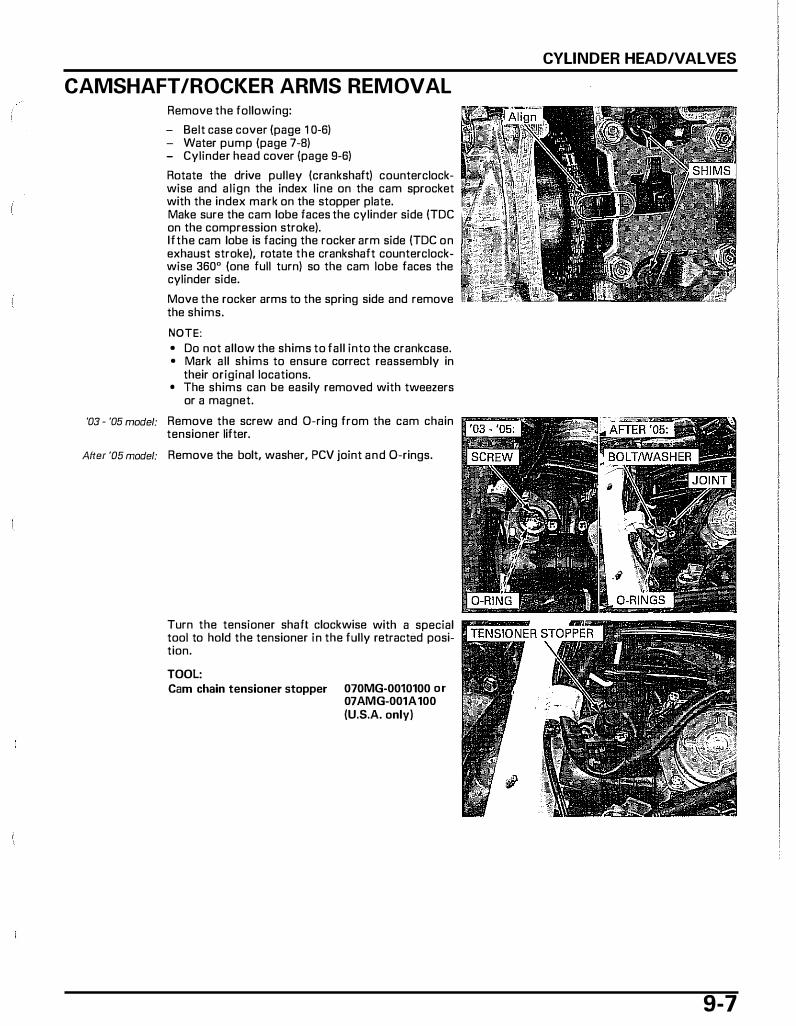
CAMSHAFT /ROCKER ARMS REMOVAL Remove the following:
- Belt case cover (page 1 0-6) - Water pump (page 7-8) - Cylinder head cover (page 9-6)
Rotate the drive pulley (crankshaft) counterclockwise and align the index line on the cam sprocket with the index mark on the stopper plate. Make sure the cam lobe faces the cylinder side (TDC on the compression stroke). lfthe cam lobe is facing the rocker arm side (TDC on exhaust stroke), rotate the crankshaft counterclockwise 360" (one full turn) so the cam lobe faces the cylinder side.
Move the rocker arms to the spring side and remove the shims.
NOTE: • Do not allow the shims to fall into the crankcase. • Mark all shims to ensure correct reassembly in
their original locations. • The shims can be easily removed with tweezers
or a magnet.
'03 - '05 model: Remove the screw and D-ring from the cam chain r.'��..., tensioner lifter.
After '05 model: Remove the bolt, washer, PCV joint and 0-rings.
Turn the tensioner shaft clockwise with a special tool to hold the tensioner in the fully retracted position.
TOOL: Cam chain tensioner stopper 070MG-0010100 or
07 AMG-001A 100 (U.S.A. only)
CYLINDER HEAD/VALVES
9-7
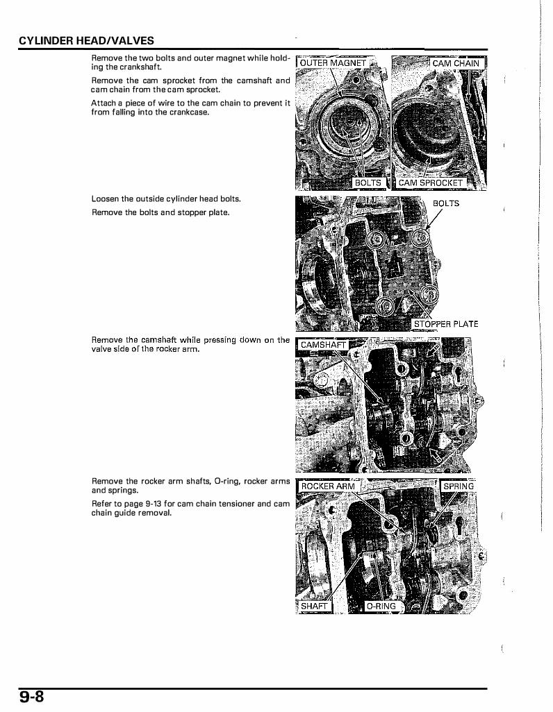
CYLINDER HEAD/VALVES
9-8
Remove the two bolts and outer magnet while hold-ing the crankshaft.
Remove the cam sprocket from the camshaft and cam chain from the cam sprocket.
Attach a piece of wire to the cam chain to prevent it from falling into the crankcase.
Loosen the outside cylinder head bolts.
Remove the bolts and stopper plate.
Remove the rocker arm shafts, D-ring, rocker arms and springs.
Refer to page 9-13 for cam chain tensioner and cam chain guide removal.
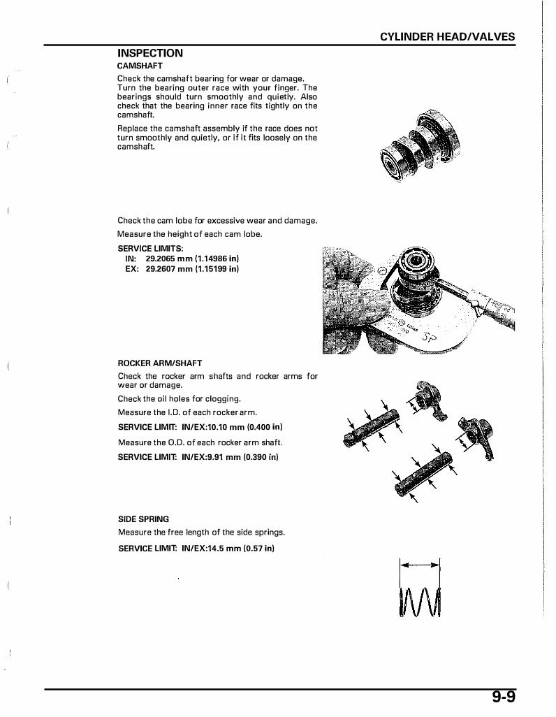
INSPECTION CAMSHAFT
Check the camshaft bearing for wear or damage. Turn the bearing outer race with your finger. The bearings should turn smoothly and quietly. Also check that the bearing inner race fits tightly on the camshaft.
Replace the camshaft assembly if the race does not turn smoothly and quietly, or if it fits loosely on the camshaft.
Check the cam lobe for excessive wear and damage.
Measure the height of each cam lobe.
SERVICE LIMITS: IN: 29.2065 mm (1.14986 in) EX: 29.2607 mm (1.15199 in)
ROCKER ARM/SHAFT
Check the rocker arm shafts and rocker arms for wear or damage.
Check the oil holes for clogging.
Measure the I. D. of each rocker arm.
SERVICE LIMIT: IN/EX:10.10 mm (0.400 in)
Measure the O.D. of each rocker arm shaft.
SERVICE LIMIT: IN/EX:9.91 mm (0.390 in)
SIDE SPRING
Measure the free length of the side springs.
SERVICE LIMIT: IN/EX:14.5 mm (0.57 in)
CYLINDER HEAD/VALVES
ll\1\ 9-9
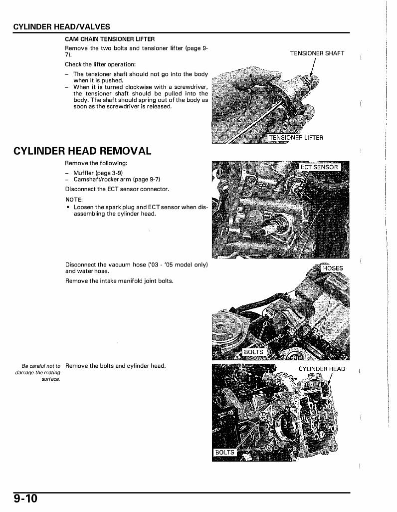
CYLINDER HEAD/VALVES
CAM CHAIN TENSIONER LIFTER
Remove the two bolts and tensioner lifter (page 9-7).
Check the lifter operation:
- The tensioner shaft should not go into the body when it is pushed.
- When it is turned clockwise with a screwdriver, the tensioner shaft should be pulled i nto the body. The shaft should spring out of the body as soon as the screwdriver is released.
CYLINDER HEAD REMOVAL Remove the following:
- Muffler (page 3-9) - Camshaft/rocker arm (page 9-7)
Disconnect the ECT sensor connector.
NOTE: • Loosen the spark plug and ECT sensor when dis
assembling the cylinder head.
Disconnect the vacuum hose ('03 - '05 model only) and water hose.
Remove the intake manifold joint bolts.
Be careful not to Remove the bolts and cylinder head. damage the mating
surface.
9 - 1 0
TENSIONER SHAFT

Remove the gasket and dowel pins.
Remove the 0-ring from the i ntake manifold groove.
CYLINDER HEAD DISASSEMBLY
To prevent loss of tension, do not
compress the valve springs more than
Remove the spark plug and ECT sensor from the cylinder head.
Remove the valve spring cotters using the special tools.
TOOL: necessary to Valve spring compressor
remove the cotters. Valve spring compressor attachment
07757·0010000
07GME-KT70200
Mark all parts during disassembly so they can be placed
back in their original locations.
Remove the valve spring compressor, then remove the following:
- Retainers - Valve springs - Spring seats - Valves - Stem seals
SPARK PLUG
CYLINDER HEAD/VALVES
D-RING
GASKET
VALVE SPRING COMPRESSOR
9-1 1
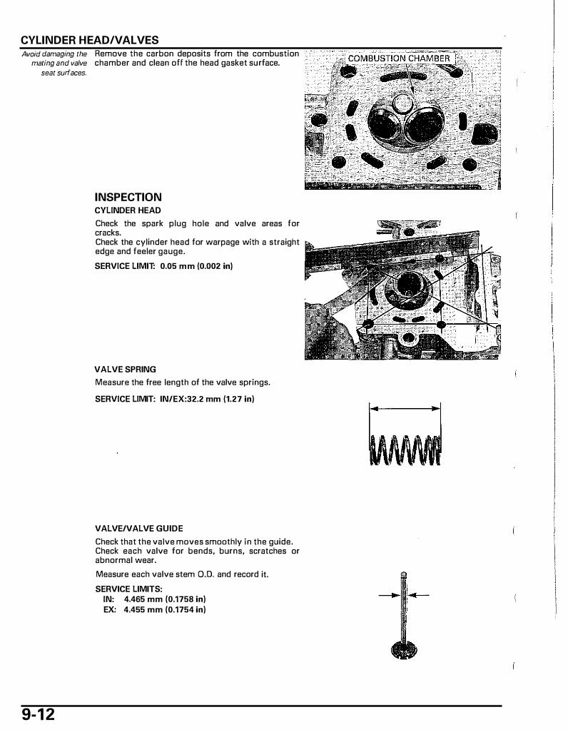
CYLINDER HEAD/VALVES Avoid damaging the Remove the carbon deposits from the combustion
mating and valve chamber and clean off the head gasket surface. seat surfaces.
9-1 2
INSPECTION CYLINDER HEAD
Check the spark plug hole and valve areas for cracks. Check the cylinder head for warpage with a straight edge and feeler gauge.
SERVICE LIMIT: 0.05 mm (0.002 in)
VALVE SPRING
Measure the free length of the valve springs.
SERVICE LIMIT: IN/EX:32.2 mm (1.27 in)
VALVE/VALVE GUIDE
Check that the valve moves smoothly in the guide. Check each valve for bends, burns, scratches or abnormal wear.
Measure each valve stem D.O. and record it.
SERVICE LIMITS: IN: 4.465 mm (0.1758 in) EX: 4.455 mm (0.1754 in)
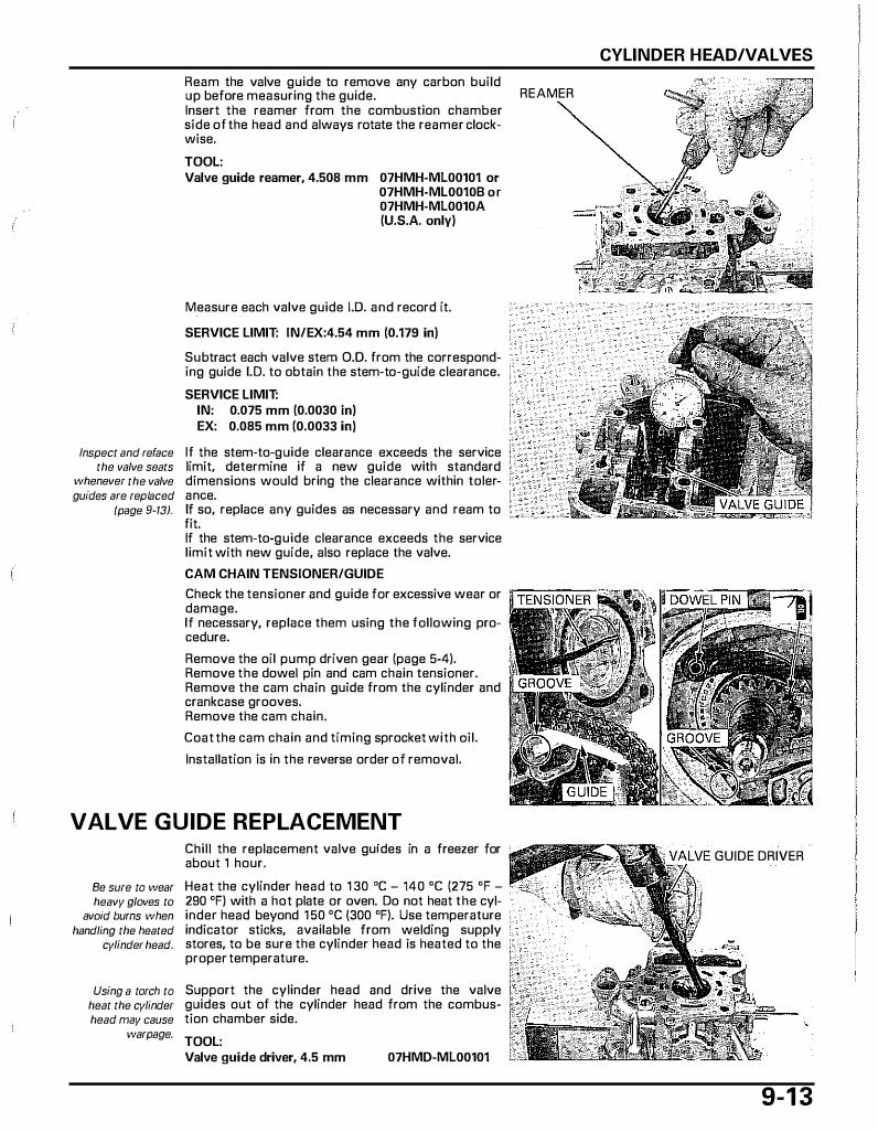
Ream the valve guide to remove any carbon build up before measuring the guide. REAMER Insert the reamer from the combustion chamber side of the head and always rotate the reamer clock-wise.
TOOL: Valve guide reamer, 4.508 mm 07HMH-ML00101 or
07HMH-ML0010B or 07HMH-ML0010A {U.S.A. only)
M_easure each valve guide 1.0. and record it.
SERVICE LIMIT: IN/EX:4.54 mm {0.179 in)
Subtract each valve stem 0.0. from the corresponding guide I. D. to obtain the stem-to-guide clearance.
SERVICE LIMIT: IN: 0.075 mm {0.0030 in) EX: 0.085 mm {0.0033 in)
Inspect and reface If the stem-to-guide clearance exceeds the service the valve seats limit, determine if a new guide with standard
whenever the valve dimensions would bring the clearance within tolerguides are replaced a nee.
(page 9-13). If so, replace any guides as necessary and ream to fit. If the stem-to-guide clearance exceeds the service limit with new guide, also replace the valve.
CAM CHAIN TENSIONER/GUIDE
Check the tensianer and guide far excessive wear or damage. If necessary, replace them using the fallowing procedure.
Remove the oil pump driven gear {page 5-4). Remove the dowel pin and cam chain tensianer. Remove the cam chain guide from the cylinder and crankcase grooves. Remove the cam chain.
Coat the cam chain and timing sprocket with ail.
Installation is in the reverse order of removal.
VALVE GUIDE REPLACEMENT
Be sure to wear heavy gloves to
avoid burns when handling the heated
cylinder head.
Using a torch to heat the cylinder head may cause
warpage.
Chill the replacement valve guides in a freezer far about 1 hour.
Heat the cylinder head to 1 30 'C - 140 'C {275 'F -290 'F) with a hot plate or oven. Do not heat the cylinder head beyond 1 50 'C {300 'F). Use temperature indicator sticks, available from welding supply stares, to be sure the cylinder head is heated to the proper temperature.
Support the cylinder head and drive the valve guides out of the cylinder head from the combustion chamber side.
TOOL: Valve guide driver, 4.5 mm 07HMD-ML00101
CYLINDER HEAD/VALVES
GUIDE DRIVER
9-1 3
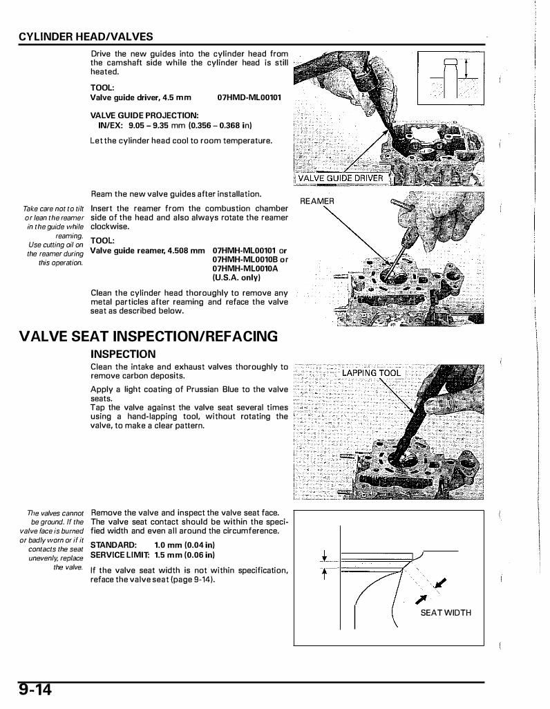
CYLINDER HEAD/VALVES
Drive the new guides into the cylinder head from the camshaft side while the cylinder head is still heated.
TOOL: Valve guide driver, 4.5 mm 07HMD-ML00101
VALVE GUIDE PROJECTION: IN/EX: 9.05 - 9.35 mm (0.356 - 0.368 in)
Let the cylinder head cool to room temperature.
Ream the new valve guides after installation.
Take care not to tilt Insert the reamer from the combustion chamber or lean the reamer side of the head and also always rotate the reamer in the guide while clockwise.
reaming. Use cutting oil on the reamer during
this operation.
TOOL: Valve guide reamer, 4.508 mm 07HMH-ML00101 or
07HMH-ML0010B or 07HMH-ML0010A (U.S.A. only)
Clean the cylinder head thoroughly to remove any metal particles after reaming and reface the valve seat as described below.
VALVE SEAT INSPECTION/REFACING
INSPECTION
The valves cannot be ground. ff the
valve face is burned or badly worn or if it
contacts the seat unevenly. replace
the valve.
9-14
Clean the intake and exhaust valves thoroughly to remove carbon deposits.
Apply a light coating of Prussian Blue to the valve seats. Tap the valve against the valve seat several times using a hand-lapping tool, without rotating the valve, to make a clear pattern.
Remove the valve and inspect the valve seat face. The valve seat contact should be within the specified width and even all around the circumference.
STANDARD: 1.0 mm (0.04 in) SERVICE LIMIT: 1.5 mm (0.06 in)
If the valve seat width is not within specification, reface the valve seat (page 9-14).
REAMER
// � SEAT WIDTH
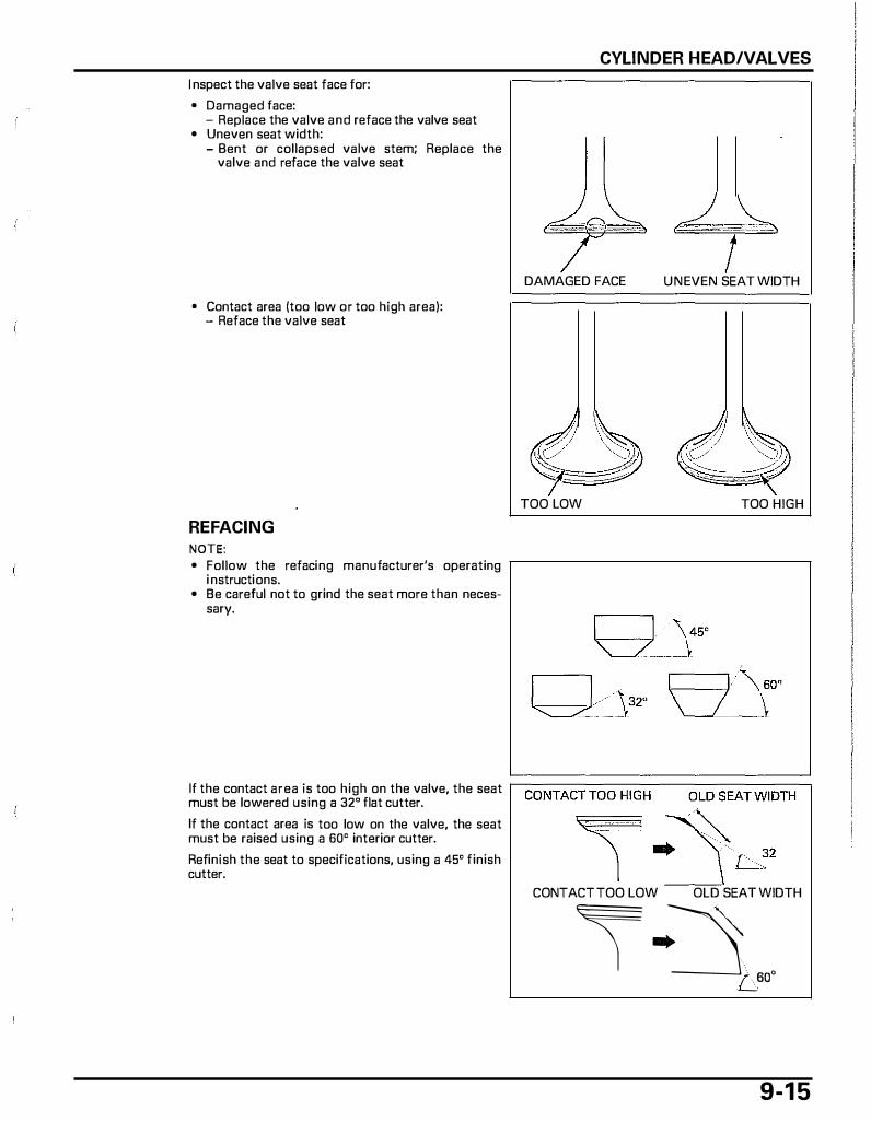
I nspect the valve seat face for:
• Damaged face: - Replace the valve and reface the valve seat
• Uneven seat width: - Bent or collapsed valve stem; Replace the
valve and reface the valve seat
• Contact area (too low or too high area): - Reface the valve seat
REF ACING NOTE: • Follow the refacing manufacturer's operating
i nstructions. • Be careful not to grind the seat more than neces
sary.
CYLINDER HEAD/VALVES
DAMAGED FACE
jj � � ·" � TOO LOW
UNEVEN SEAT WIDTH
J/ 1\ /j ��-, \(�. ····� �'( TOO HIGH
If the contact area is too high on the valve, the seat �c=o=N=T=A=C=T=T=o=o=H=IG=H===O=L=O=S=E=A=T=W=l=D=T=H� must be lowered using a 32° flat cutter.
If the contact area is too low on the valve, the seat must be raised using a 60° interior cutter.
Refinish the seat to specifications, using a 45° finish cutter. ����
CONTACT TOO LOW OLD SEAT WIDTH
� -�[ooo 9-1 5
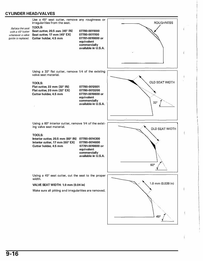
CYLINDER HEAD/VALVES
Use a 45° seat cutter, remove any roughness or irregularities from the seat.
Reface the seat TOOLS:
with a 45°cutter Seat cutter, 20.5 mm {45° IN)
whenever a valve Seat cutter, 17 mm (45° EX) guide is replaced. Cutter holder, 4.5 mm
07780-0011000 07780-0011100 07781-0010600 or equivalent commercially available in U.S.A.
Using a 32° flat cutter, remove 114 of the existing valve seat material.
TOOLS: Flat cutter, 22 mm (32° IN) Flat cutter, 20 mm (32° EX) Cutter holder, 4.5 mm
07780-0012601 07780-0013200 07781-0010600 or equivalent commercially available in U.S.A.
Using a 60° interior cutter, remove 1/4 of the exist- �================�
9-1 6
ing valve seat material.
TOOLS: Interior cutter, 20.5 mm (60° IN) Interior cutter, 17 mm (60° EX) Cutter holder, 4.5 mm
07780-0014300 07780-0014600 07781-0010600 or equivalent commercially available in U.S.A.
\ soo--.6 Using a 45° seat cutter, cut the seat to the proper �================� width.
VALVE SEAT WIDTH: 1.0 mm (0.04 in)
Make sure all pitting and i rregularities are removed.
�-0 mm (0.039 in)

Excessive lapping After cutting the seat, apply lapping compound to pressure mav the valve face, and lap the valve using light pres
deform or damage sure. the seat, Change the angle of the lapping tool frequently to
Do not allow lap- prevent uneven seat wear, ping compound to After lapping, wash any residual compound off the enter the guides. cylinder head and valve and recheck the seat con
tact.
CYLINDER HEAD ASSEMBLY
SPARK PLUG
EXHAUST VALVE
Blow through al l oil passages in the cylinder head with compressed air. Apply engine oil to the inner surface of new stem seals. Install the spring seats and stem seals. Lubricate the valve stem sliding surface with molybdenum oil solution. Insert the valves into the guide while turning it slowly to avoid damage to the stem seals.
CYLINDER HEAD/VALVES
LAPPING TOOL
ECT SENSOR
SPRING
SPRING SEAT
STEM SEAL
VALVE GUIDE
SPRING
RETAIN>..a \� IE�-. \ SPRING SEAT
Ill . STEM SEAL ttt
9- 1 7

CYLINDER HEAD/VALVES
Install the valve springs with the tightly wound coils facing the combustion chamber. Install the spring retainers.
Grease the cotters Install the valve spring cotters using the special to ease installation. tools.
To prevent loss of tension, do not
compress the valve spring more than
necessary to remove the cotters.
TOOLS: Valve spring compressor Valve spring compressor
attachment
07757-0010000
07GME-KT70200
Support the cylinder head so the valve heads will not contact anything that cause damage. Tap the valve stems gently with two plastic hammers as shown to seat the cotters firmly.
CYLINDER HEAD INSTALLATION
9-1 8
Clean the mating surface of the cylinder and cylinder head. Install the cam chain, cam chain guide and tensioner (page 9-13).
Install the dowel pins and a new gasket onto the cylinder. Coat a new D-ring with oil and install it into the groove of the intake manifold.
COMBUSTION CHAMBER
__.... lAAMNI
VALVE SPRING COMPRESSOR
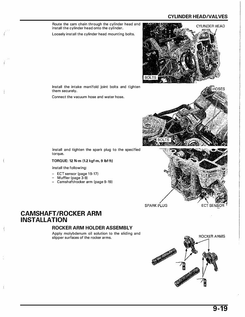
Route the cam chain through the cylinder head and install the cylinder head onto the cylinder. Loosely install the cylinder head mounting bolts.
Install the intake manifold joint bolts and tighten them securely. Connect the vacuum hose and water hose.
Install and tighten the spark plug to the specified torque. TORQUE: 12 N·m (1.2 kgf·m, 9 lbf.ft) Install the following: - ECT sensor (page 1 9-17) - M uffler (page 3-9) - Camshaft/rocker arm (page 9-19)
CAMSHAFT /ROCKER ARM INSTALLATION
ROCKER ARM HOLDER ASSEMBLY Apply molybdenum oil solution to the sliding and slipper surfaces of the rocker arms.
CYLINDER HEAD/VALVES
9-19
CYLINDER HEAD/VALVES
Install the rocker a rms and side springs as shown. Coat a new D-ring with oil .
Install the intake Apply engine oi l to the sliding surfaces of the rocker shaft with the cut- arm shafts and install it with a new 0-ring to the cylout facing outside. inder head.
9-20
Apply oi l to the camshaft bearings. Apply molybdenum oil solution to the cam lobes. Install the camshaft with the cam lobe facing the cylinder side while pressing down the valve side of the rocker arms.
Apply engine oil to the cylinder head bolt threads and seating surfaces. Install the stopper plate onto the cylinder head as shown. Install the bolts and tighten them in a crisscross pattern in two or three steps to the specified torque. TORQUE: 12 N·m (1.2 kgf·m, 9 lbf·ftl
If the cylinder head is removed, tighten the outside cylinder head bolts.
Turn the drive pulley (crankshaft) counterclockwise and align the "T" mark on the flywheel with the index mark on the crankcase while holding the cam chain. Make sure the cam lobe faces the cylinder side (TDC on the compression stroke). Install the cam sprocket onto the cam chain, aligning the index l ine on the cam sprocket with the index mark on the stopper plate.
Apply engine oil to the cam sprocket bolt threads and seating suriaces. Apply engine oil to the cam sprocket gear teeth. Clean the inside of the outer magnet and check that no nuts or bolts are attached to the magnet. Install the outer magnet and bolts. Tighten the bolts to the specified torque while holding the crankshaft. TORQUE: 8.8 N·m (0.9 kgf·m, 6.5 lbf·ft)
Install the valve shims in their original locations noted during the removal.
Turn the tensianer shaft clockwise with a special tool to hold the tensioner in the fully retracted position.
TOOL: Cam chain tensioner stopper 070MG-0010100
Install a new gasket to the cam chain tensioner lifter. Install the cam chain tensioner on the cylinder and tighten the bolts securely.
'03 • '05 model: Remove the special tool to cancel the lock of the tensianer lifter. Coat a new 0-ring with oil. Install and tighten the lifter screw to the specified torque. TORQUE: 4.2 N·m (0.43 l<gf·m, 3.1 lbf·ft)
CYLINDER HEAD/VALVES
9-21
CYLINDER HEAD/VALVES
After '05 model: Remove the special tool to cancel the lock of the tensioner l ifter. Coat new 0-rings with oil. Install new 0-rings to the PCV joint and cam chain tensioner l ifter groove. Install the PCV joint to the cam chain tensioner.
After '05 model: Install the bolt and washer. Tighten the bolt to the specified torque. TORQUE: 10 N·m (1.0 lcgf·m, 7 lbf.ft) Make sure the index line on the cam sprocket aligns with the index mark on the stopper plate when the "T" mark on the flywheel is aligned with the index mark on the crankcase. Install the following: - Water pump (page 7-10) - Belt case cover (page 10-6)
CYLINDER HEAD COVER INSTALLATION
9-22
Clean the gasket g roove of the cylinder head cover. Coat the new 0-rings with oil and install them into the grooves of the cylinder head cover.
Install the cylinder head cover to the cylinder head. Install the bolts and tighten them in a crisscross pattern in two or three steps. Connect the engine breather and air supply hoses. Install the fuel tank (page 6-28).
0-RINGS �., ...... ,
1 0. KICKSTARTER/DRIVE PULLEY/DRIVEN PULLEY/CLUTCH
COMPONENT LOCATIONs ......................... 10-2 KICKSTARTER .............................................. 10-6
SERVICE INFORMATION ···························· 10 -3 DRIVE PULLEY··············································10-9
TROUBLESHOOTING .................................. 10-5 I CLUTCH/DRIVEN PULLEY·························10 -12 ..: BELT CASE COVER ····································· 10-6
1 0- 1
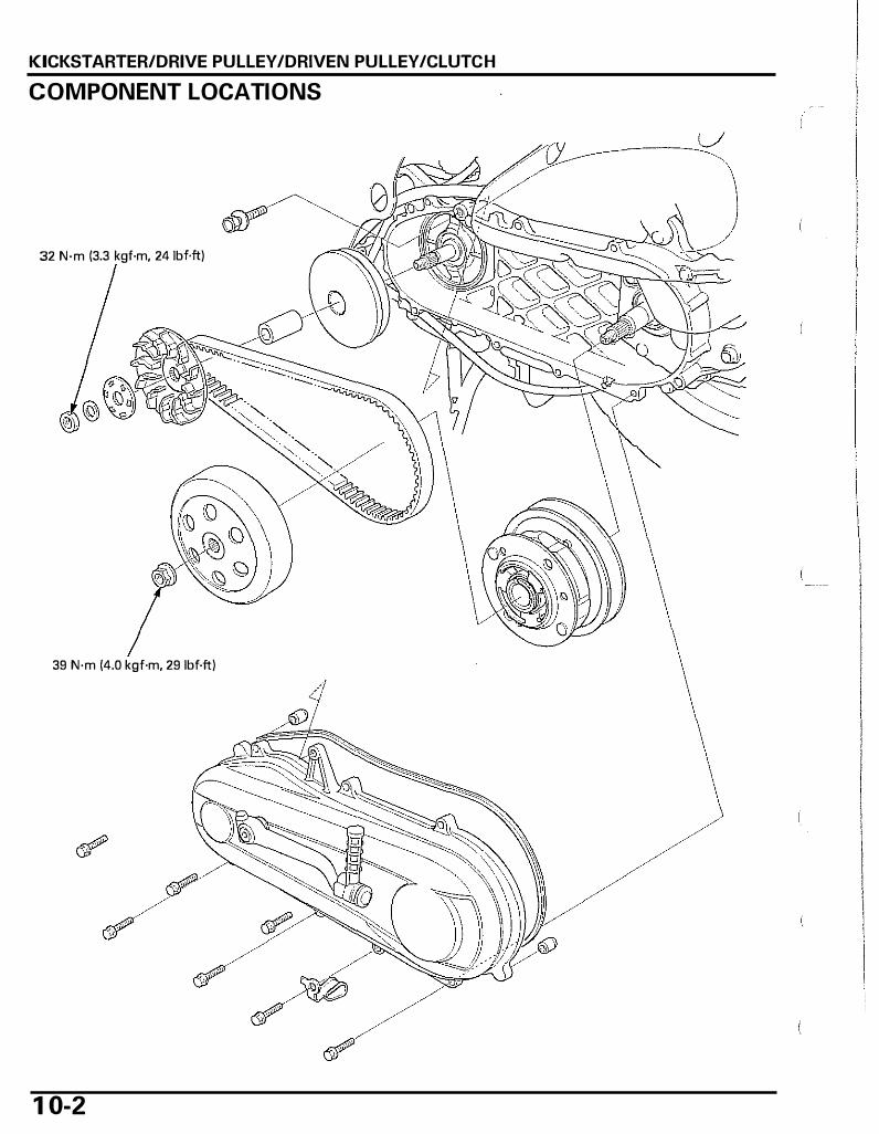
KICKSTARTER/DRIVE PULLEY/DRIVEN PULLEY/CLUTCH
COMPONENT LOCATIONS
./Jl -------':::L/
32 N·m (3.3 kgf·m, 24 1bf.ft)
39 N·m (4.0 kgf·m, 29 lbf.ft)
1 0-2

KICKSTARTER/DRIVE PULLEY /DRIVEN PULLEY /CLUTCH
SERVICE INFORMATION
GENERAL
• This section covers maintenance of the kickstarter, drive pulley, driven pulley and clutch. • These services can be done with the engine installed in the frame. • Avoid getting grease and oil on the V-belt and pulley drive faces in order to prevent belt slippage. • Do not apply grease to the movable drive face and weight rollers.
SPECIFICATIONS
ITEM STANDARD I Clutch I Clutch outer I. D. 1 07.0 1 07.2 (4.21 4.22) I I Lining thickness - I Drive belt width 1 8. 1 5 (0.715) I Movable drive face Bushing I.D. 20.035 - 20.085 (0.7888 - 0.7907) I
Boss O.D. 20.010 20.025 (0.7878 0.7884) Weight roller O.D. 1 5.92 - 1 6.08 (0.627 - 0.633)
Driven pulley Face spring face length 90.8 (3.57) Driven face O.D. 33.950 - 33.970 ( 1.3366 - 1.3374) Movable driven face I. D. 34.015 34.035 ( 1.3392 1.3400)
TORQUE VALUES
Unit· mm (in) SERVICE LIMIT
1 07.5 (4.23) 2.0 (0.08)
1 7. 1 5 (0.68) 20.13 (0.793) 19.97 (0.786)
1 5.4 (0.61 ) 86.0 (3.39)
33.70 ( 1.327) 34.29 (1.350)
Drive pulley face nut Clutch outer nut
32 N·m (3.3 kgf·m, 24 lbf.ft) 39 N·m (4.0 kgf·m, 29 lbf.ft)
Apply oil to the threads and flange surface
1 0-3
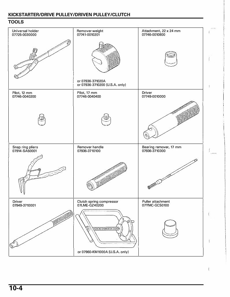
KICKSTARTER/DRIVE PULLEY /DRIVEN PULLEY /CLUTCH
TOOLS
Universal holder 07725-0030000
Pilot, 12 mm 07746-0040200
Snap ring pliers 07914-SA50001
Driver 07949-3710001
1 0-4
Remover weight 07741-0010201
or 07936-371020A or 07936-3710200 (U.S.A. only)
Pilot, 17 mm 07746-0040400
Remover handle 07936-3710100
Clutch spring compressor 07LME-GZ40200
or 07960-KM 1000A (U.S.A. only)
Attachment, 22 x 24 mm 07746-0010800
Driver 07749-0010000
Bearing remover, 17 mm 07936-3710300
Puller attachment 07YMC-GCS0100
TROU BLESHOOTING Engine starts but scooter won't move • Worn drive belt • Damaged ramp plate • Worn or damaged clutch shoe • Broken driven face spring Engine stalls or scooter creeps • Broken clutch shoe spring
KICKSTARTER/DRIVE PULLEY /DRIVEN PULLEY /CLUTCH
Poor performance at high speed or lack of power • Worn drive belt • Weak driven face spring • Worn weight rollers • Contaminated pulley faces
1 0-5
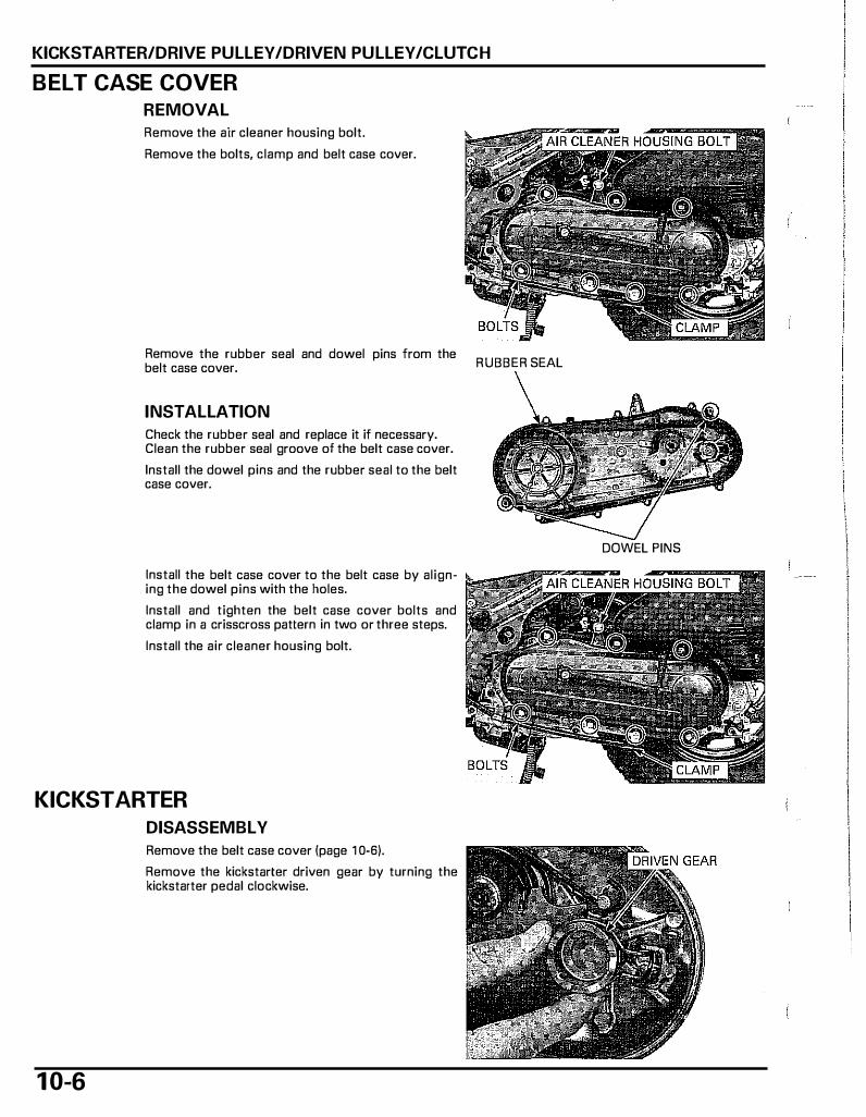
KICKSTARTER/DRIVE PULLEY /DRIVEN PULLEY /CLUTCH
BELT CASE COVER
REMOVAL
Remove the air cleaner housing bolt. Remove the bolts, clamp and belt case cover.
Remove the rubber seal and dowel pins from the belt case cover.
INSTALLATION
Check the rubber seal and replace it if necessary. Clean the rubber seal groove of the belt case cover. Install the dowel pins and the rubber seal to the belt case cover.
Install the belt case cover to the belt case by aligning the dowel pins with the holes. Install and tighten the belt case cover bolts and clamp in a crisscross pattern in two or three steps. Install the air cleaner housing bolt.
KICKSTARTER
DISASSEMBLY
1 0-6
Remove the belt case cover (page 1 0-6).
Remove the kickstarter driven gear by turning the kickstarter pedal clockwise.
RUBBER SEAL
DOWEL PINS
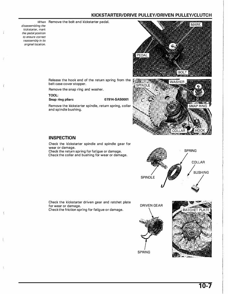
KICKSTARTER/DRIVE PULLEY/DRIVEN PULLEY/CLUTCH
When Remove the bolt and kickstarter pedal. disassembling the
kickstarter, mark the pedal position to ensure correct reassemblv in its original location.
Release the hook end of the return spring from the belt case cover stopper. Remove the snap ring and washer. TOOL: Snap ring pliers 07914-SA50001
Remove the kickstarter spindle, return spring, collar and spindle bushing.
INSPECTION
Check the kickstarter spindle and spindle gear for wear or damage. Check the return spring for fatigue or damage. Check the collar and bushing for wear or damage.
Check the kickstarter driven gear and ratchet plate for wear or damage. Check the friction spring for fatig ue or damage.
SPRING
SPINDLE
DRIVEN GEAR
SPRING
1 0-7

KICKSTARTER/DRIVE PULLEY /DRIVEN PULLEY /CLUTCH
Check the journals of the belt case cover for wear or damage.
ASSEMBLY
COLLAR
RETURN SPRING
KICKSTARTER SPINDLE STARTER DRIVEN GEAR
1 0-8
Install the spindle bushing and collar onto the belt case cover. Install the return spring as shown. Apply molybdenum paste 0.2 - 0.5 gram to the kickstarter spindle sliding surface. Install the kickstarter spindle to the belt case cover and hook the return spring end to the groove of the kickstarter spindle.
WASHER
GROOVE
KICKSTARTER PEDAL
SNAP RING
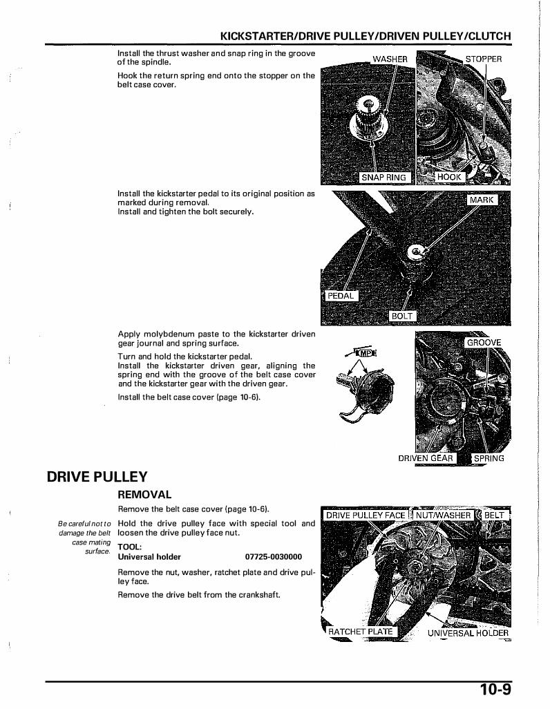
KICKSTARTER/DRIVE PULLEY /DRIVEN PULLEY /CLUTCH
Install the thrust washer and snap ring in the groove of the spindle. Hook the return spring end onto the stopper on the belt case cover.
Install the kickstarter pedal to its original position as marked during removal. Install and tighten the bolt securely.
Apply molybdenum paste to the kickstarter driven gear journal and spring surface. Turn and hold the kickstarter pedal. Install the kickstarter driven gear, aligning the spring end with the groove of the belt case cover and the kickstarter gear with the driven gear. Install the belt case cover (page 10-6).
DRIVE PULLEY
REMOVAL
Remove the belt case cover (page 10-6).
Be careful not to Hold the drive pulley face with special tool and damage the belt loosen the drive pulley face nut.
case mating surface. TOOL:
Universal holder 07725-0030000
Remove the nut, washer, ratchet plate and drive pulley face. Remove the drive belt from the crankshaft.
1 0-9

KICKSTARTER/DRIVE PULLEY/DRIVEN PULLEY/CLUTCH
1 0- 1 0
Remove the movable drive face assembly while holding the back of the ramp plate. Remove the drive face boss from the movable drive face assembly.
Remove the ramp plate and weight rollers.
INSPECTION
DRIVE BELT
Check the d rive belt for cracks, separation, abnormal or excessive wear. Measure the drive belt width. SERVICE LIMIT: 17.15 mm (0.68 in)
WEIGHT ROLLER
Check each roller for wear or damage. Measure the weight roller O.D. SERVICE LIMIT: 15.4 mm (0.61 in)
RAMP PLATE WEIGHT ROLLER

KICKSTARTER/DRIVE PULLEY /DRIVEN PULLEY /CLUTCH
MOVABLE DRIVE FACE
Check the d rive face boss far wear or damage. Measure the boss O.D. SERVICE LIMIT: 19.97 mm (0.786 in) Measure the face bushing I. D.
SERVICE LIMIT: 20.13 mm (0.793 in)
ASSEMBLY
Clean any oil and grease from the pulley faces and weight rollers. Install the weight rollers on the movable drive face. Install the ramp plate.
INSTALLATION
WEIGHT ROLLER
Clean any oil and grease from the pulley faces and 11""'...,_,_�..,·-�..,.,."""" the drive belt. Install the drive face bass into the movable drive face assembly. Install the movable drive face assembly onto the crankshaft while holding the ramp plate. Install the drive belt onto the drive face boss.
RAMP PLATE
Install the drive pulley face, ratchet plate and P""!"'"""'"".'!,..""'""!"'"!"'"F��'!'"'!'=;::�"T72�?:::::=:""1111111 washer. Apply oil to the drive pulley face nut threads and seating surface, then install the nut. Hold the drive pulley face with the special tool and tighten the nut to the specified torque. TOOL: Universal holder 07725-0030000
TORQUE: 32 N-m (3.3 l<gf·m, 24 lbf·ft) Install the belt case cover (page 1 0-6).
1 0- 1 1
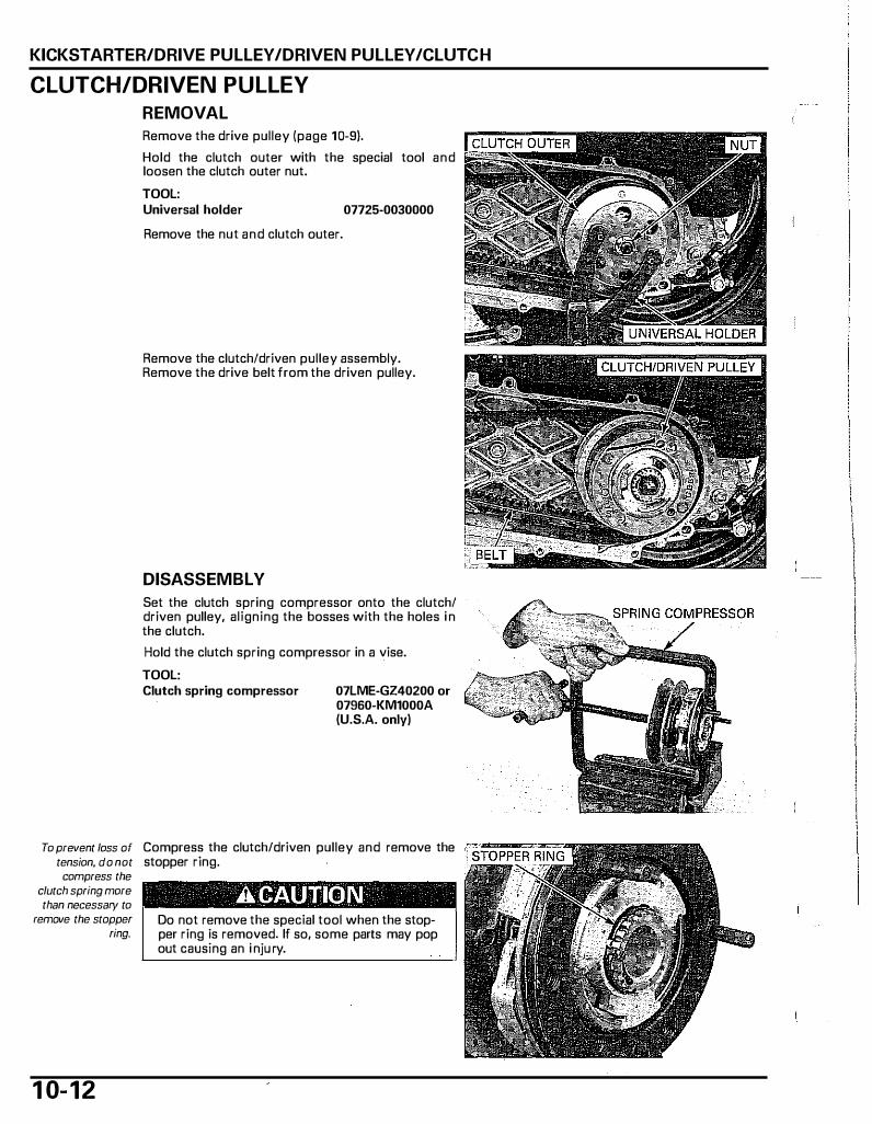
KICKSTARTER/DRIVE PULLEY/DRIVEN PULLEY/CLUTCH
CLUTCH/DRIVEN PULLEY
REMOVAL
To prevent loss of tension, do not compress the
clutch spring more than necessary to
remove the stopper ring.
1 0- 1 2
Remove the drive pulley (page 10-9).
Hold the clutch outer with the special tool and loosen the clutch outer nut. TOOL: Universal holder 07725-0030000
Remove the nut and clutch outer.
Remove the clutch/driven pulley assembly. Remove the drive belt from the driven pulley.
DISASSEMBLY
Set the clutch spring compressor onto the clutch/ driven pulley, aligning the bosses with the holes i n the clutch. Hold the clutch spring compressor in a vise. TOOL: Clutch spring compressor 07LME-GZ40200 or
07960-KM1000A (U.S.A. only)
Compress the clutch/driven pulley and remove the stopper ring.
A CAUTION Do not remove the special tool when the stopper ring is removed. If so, some parts may pop out causing an i nju ry.
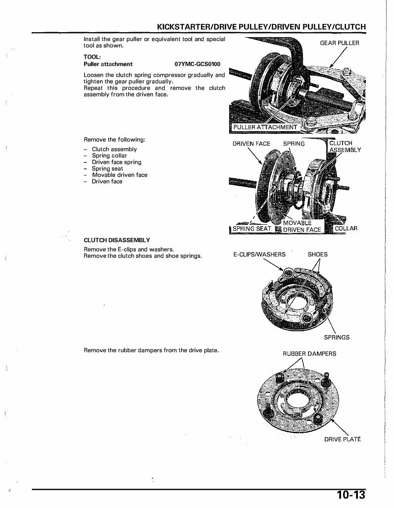
KICKSTARTER/DRIVE PULLEY /DRIVEN PULLEY /CLUTCH
Install the gear puller or equivalent tool and special tool as shown. TOOL: Puller attachment 07YMC-GCS0100
GEAR PULLER
Loosen the clutch spring compressor gradually and llllllllllllllilillllo tighten the gear puller gradually. Repeat this procedure and remove the clutch assembly from the driven face.
Remove the following: Clutch assembly
- Spring collar - Driven face spring - Spring seat - Movable driven face - Driven face
CLUTCH DISASSEMBLY
Remove the E-clips and washers. Remove the clutch shoes and shoe springs.
Remove the rubber dampers from the drive plate.
E-CLIPS/WASHERS SHOES
SPRINGS
RUBBER DAMPERS
DRIVE
1 0- 1 3

KICKSTARTER/DRIVE PULLEY/DRIVEN PULLEY/CLUTCH
1 0- 1 4
INSPECTION
CLUTCH OUTER
Check the clutch outer for wear or damage. Measure the clutch outer 1.0. SERVICE LIMIT: 107.5 mm (4.23 in)
CLUTCH SHOE LINING
Check the clutch shoe for wear or damage. Measure the thickness of each shoe.
SERVICE LIMIT: 2.0 mm (0.08 in)
DRIVEN FACE SPRING
Measure the driven face spring free length.
SERVICE LIMIT: 86.0 mm (3.39 in)
DRIVEN FACE/MOVABLE DRIVEN FACE
Check the driven face for scratches, scoring or damage. Measure the driven face boss 0.0. SERVICE LIMIT: 33.70 mm (1.327 in)
Check the movable driven face for scratches, scoring or damage. Check the guide grooves for stepped wear or damage. Measure the movable driven face 1.0. SERVICE LIMIT: 34.29 mm (1.350 in)
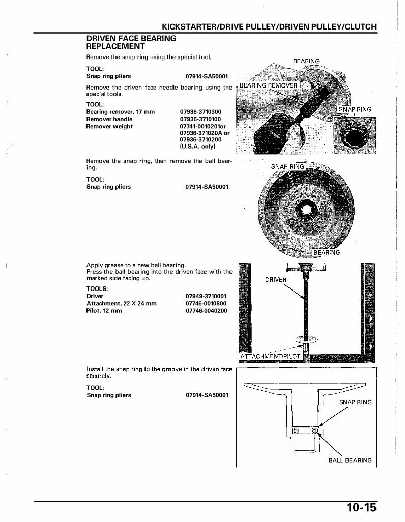
KICKSTARTER/DRIVE PULLEY/DRIVEN PULLEY/CLUTCH
DRIVEN FACE BEARING REPLACEMENT
Remove the snap ring using the special tool. TOOL: Snap ring pliers 07914-SA50001 ������� Remove the driven face needle bearing_ using the �:: special tools. TOOL: Bearing remover, 17 mm Remover handle Remover weight
07936-3710300 07936-3710100 07741-0010201or 07936-371020A or 07936-3710200 (U.S.A. only)
Remove the snap ring, then remove the ball bearing. TOOL: Snap ring pliers 07914-SA50001
Apply grease to a new ball bearing. Press the ball bearing into the driven face with the marked side facing up. TOOLS: Driver Attachment, 22 X 24 mm Pilot, 12 mm
TOOL: Snap ring pliers
07949-3710001 07746-0010800 07746-0040200
07914-SA50001 SNAP RING
BALL BEARING
1 0- 1 5

KICKSTARTER/DRIVE PULLEY /DRIVEN PULLEY /CLUTCH
1 0- 1 6
Apply grease to a new needle bearing. Press the needle bearing into the driven face with the marked side facing up. TOOLS: Driver Attachment, 22 X 24 mm Pilot, 17 mm
07749-0010000 07746-0010800 07746-0040400
Install the snap ring to the groove of the driven face securely. TOOL: Snap ring pliers 07914-SA50001
ASSEMBLY
DRIVER
ATTACHMENT
PILOT
Clean any oil and g rease from the pulley faces and clutch outer.
RUBBER DAMPERS
DRIVE PLATE
SPRING COLLAR
�� CLUTCH SHOE SPRINGS
\ � NEEDLE BEARING
BALL BEARING E-CLIP
SNAP RINGS
DRIVEN FACE
MOVABLE DRIVEN FACE
SPRING SEAT
DRIVEN FACE SPRING
Install the rubber dampers onto the drive plate. RUBBER DAMPERS
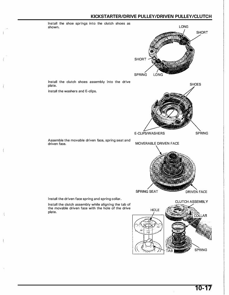
KICKSTARTER/DRIVE PULLEY /DRIVEN PULLEY /CLUTCH
Install the shoe springs into the clutch shoes as shown.
Install the clutch shoes assembly into the drive plate. Install the washers and E-clips.
LONG
SHORT
SPRING
E-CLJPS/WASHERS
Assemble the movable driven face, spring seat and driven face. MOVERABLE DRIVEN FACE
SHORT
SHOES
SPRING
I nstall the driven face spring and spring collar. Install the clutch assembly while aligning the tab of the movable driven face with the hole of the drive plate.
CLUTCH ASSEMBLY
1 0- 1 7

KICKSTARTER/DRIVE PULLEY /DRIVEN PULLEY /CLUTCH
To prevent loss of tension, do not
compress the clutch spring more than necessary to install the stopper
ring.
Be careful not to damage the spline.
1 0- 1 8
Set the clutch spring compressor over the clutch/ driven pulley assembly and compress the driven face spring.
TOOL: Clutch spring compressor 07LME-GZ40200 or
07960-KM1000A (U.S.A. only)
Align the spline of the driven face with the spline of the drive plate while compressing the clutch spring compressor.
Install the stopper ring securely.
Remove the clutch/driven pulley assembly from the spring compressor.
INSTALLATION
Rotate the movable driven face clockwise and install the drive belt into the driven pulley.
Do not get any oil and grease on the driven face inside.
Install the clutch/driven pulley assembly onto the drives haft.
Clean any oil and grease from the inside of the clutch outer.
Install the clutch outer and clutch outer nut.
Hold the clutch outer with the special tool and tighten the clutch outer nut to the specified torque.
TOOL: Universal holder 07725-0030000
TORQUE: 39 N·m (4.0 kgf·m, 29 lbf.ft)
Install the drive pulley (page 1 0-1 1 ).
COMPONENT LOCATIONs ......................... 11-2
SERVICE INFORMATION ··· · · · · · · · · · · · · · · · ·········· 11-3
TROUBLESHOOTING ···· · · · · · · · · · · · · · · · · ·············· 11-4
FINAL REDUCTION OIL ·· · · · · · · · · · · · · · ·· · · · · · · · · · · · · · · 11-5
1 1 . FI NAL REDUCTION
FINAL REDUCTION DISASSEMBLY···· · · · · · · · ·11-5
BEARING REPLACEMENT ·· · · · · · · · · · · · · · · · · · · · · ·····11-8
FINAL REDUCTION ASSEMBLY·· · · · · · · · · · · · ·····11-9
1 1 -1
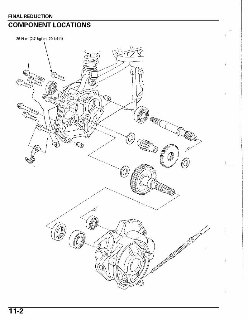
FINAL REDUCTION
LOCATIONS COMPONENT
26 ·m · N 12 7 kgf·m, 20 lbf.ft)
1 1 -2

SERVICE INFORMATION
GENERAL • This section covers maintenance of the final reduction. • These services can be done with the engine installed in the frame.
FINAL REDUCTION
• When installing the drive shaft, be sure to use the special tool; position the special tool against the bearing inner race and pull the drive shaft i nto the bearing.
SPECIFICATIONS
ITEM Final reduction oi l capacity (at disassembly) Recommended final reduction oil
TORQUE VALUES
Final reduction oil check bolt TOOLS
Bearing remover weight 07741-0010201
or 07936-371020A or 07936-3710200 (U.S.A. only)
Pilot, 12 mm 07746-0040200
1 3 N·m (1.3 kgf·m, 9 lbf·ft)
Attachment, 32 x 35 mm 07746-0010100
Pilot, 17 mm 07746-0040400
SPECIFICATIONS 0.1 l iter (0.11 US qt, 0.09 1mp qt)
Hypoid gear oil #90
Attachment, 37 x 40 mm 07746-0010200
�} \�. _:::/:'
Driver 07749-0010000
1 1 -3
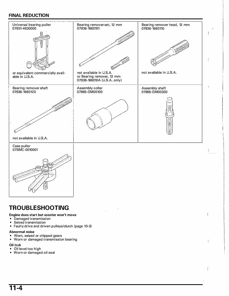
FINAL REDUCTION
Universal bearing puller 07931-4630000
or equivalent commercially available in U.S.A.
Bearing remover shaft 07936-1660120
not available in U.S.A.
Case puller 07SMC-0010001
TROUBLESHOOTING Engine does start but scooter won't move • Damaged transmission • Seized transmission
Bearing remover set, 12 mm 07936-1660101
'
not available in U.S.A. or Bearing remover, 12 mm 07936-166010A (U.S.A. only)
Assembly collar 07965-GM00100
• Faulty drive and driven pulleys/clutch (page 10-3) Abnormal noise • Worn, seized or chipped gears • Worn or damaged transmission bearing Oil leak • Oil level too high • Worn or damaged oil seal
1 1 -4
Bearing remover head, 12 mm 07936-1660110
not available in U.S.A.
Assembly shaft 07965-GM00300
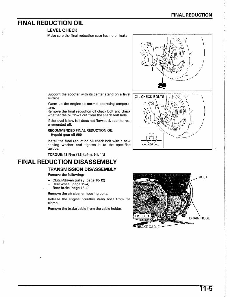
FINAL REDUCTION OIL
LEVEL CHECK Make sure the final reduction case has no oil leaks.
FINAL REDUCTION
Support the scooter with its center stand on a level �===============� surface. Warm up the engine to normal operating temperature. Remove the final reduction oil check bolt and check whether the oil flows out from the check bolt hole. If the level is low (oil does not flow out), add the rec· om mended oil. RECOMMENDED FINAL REDUCTION OIL:
Hypoid gear oil #90
Install the final reduction oil check bolt with a new sealing washer and tighten it to the specified torque. TORQUE: 13 N·m (1.3 kgf·m, 9 1bf.ft)
FINAL REDUCTION DISASSEMBLY
TRANSMISSION DISASSEMBLY Remove the following: - Clutch/driven pulley (page 1 0-12) - Rear wheel (page 1 5-4) - Rear brake (page 1 5-4)
Remove the a ir cleaner housing bolts. Release the engine breather drain hose from the clamp. Remove the brake cable from the cable holder.
BOLT
DRAIN HOSE
1 1 -5

FINAL REDUCTION
1 1 -6
Remove the seven bolts and hose clamp. Remove the transmission case and drain all oil to the suitable container from the transmission case.
Remove the dowel pins. Clean any sealant from the transmission case mating su rface.
Remove the thrust washers and countershaft. Remove the final gear shaft, counter gear and side washer. Clean the transmission case mating surface.
DRIVESHAFT REMOVAL Remove the driveshaft using the special tool.
TOOL: Case puller 07SMG-0010001 Remove the driveshaft oil seal and bearing.
COUNTERSHAFT FINAL GEAR SHAFT
OIL SEAUBEARING
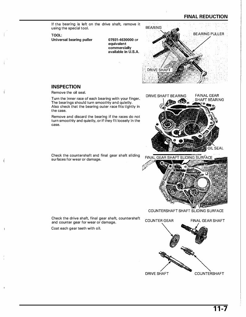
If the bearing is left on the drive shaft, remove it using the special tool. TOOL: Universal bearing puller
INSPECTION Remove the oil seal.
07931-4630000 or equivalent commercially available in U.S.A.
Turn the inner race of each bearing with your finger. The bearings should turn smoothly and quietly. Also check that the bearing outer race fits tightly in the case. Remove and discard the bearing if the races do not turn smoothly and quietly, or if they fit loosely in the case.
Check the countershaft and final gear shaft sliding surfaces for wear or damage.
Check the drive shaft, final gear shaft, countershaft and counter gear for wear or damage. Coat each gear teeth with oil.
FINAL REDUCTION
BEARING PULLER
DRIVE SHAFT BEARING
·�;. �{:
COUNTERSHAFT SHAFT SLIDING SURFACE
COUNTER G EAR FINAL GEAR SHAFT
'I DRIVE SHAFT COUNTERSHAFT
1 1 -7

FINAL REDUCTION
BEARING REPLACEMENT
DRIVE SHAFT DRIVE SHAFT BEARING (6203)
FINAL GEAR SHAFT BEARING (6203UU)
OIL SEAL FINAL GEAR SHAFT
�___][_____J_J_�/
Be careful not to Remove the final gear shaft oil seal and bearing. damage the trans-mission case mat-
ing surface.
1 1-8
OIL SEAL
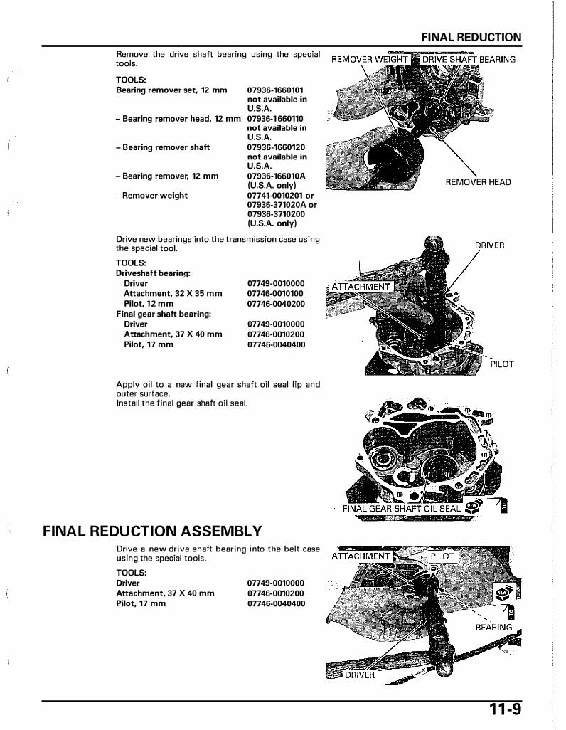
Remove the drive shaft bearing using the special tools. TOOLS: Bearing remover set, 12 mm 07936-1660101
not available in U.S.A.
- Bearing remover head, 12 mm 07936-1 660110 not available in U.S.A.
- Bearing remover shaft 07936-1660120
- Bearing remover, 12 mm
- Remover weight
not available in U.S.A. 07936-166010A (U.S.A. only) 07741-0010201 or 07936-371020A or 07936-3710200 (U.S.A. only)
Drive new bearings into the transmission case using the special tool. TOOLS: Driveshaft bearing:
Driver Attachment, 32 X 35 mm Pilot, 12 mm
Final gear shaft bearing: Driver Attachment, 37 X 40 mm Pilot, 17 mm
07749-0010000 07746-0010100 07746-0040200
07749-0010000 07746-0010200 07746-0040400
Apply oil to a new final gear shaft oil seal lip and outer surface. Install the final gear shaft oil seal.
FINAL REDUCTION ASSEMBLY Drive a new drive shaft bearing i nto the belt case using the special tools. TOOLS: Driver Attachment, 37 X 40 mm Pilot, 17 mm
07749-0010000 07746-0010200 07746-0040400
FINAL REDUCTION
REMOVER HEAD
PILOT
1 1 -9
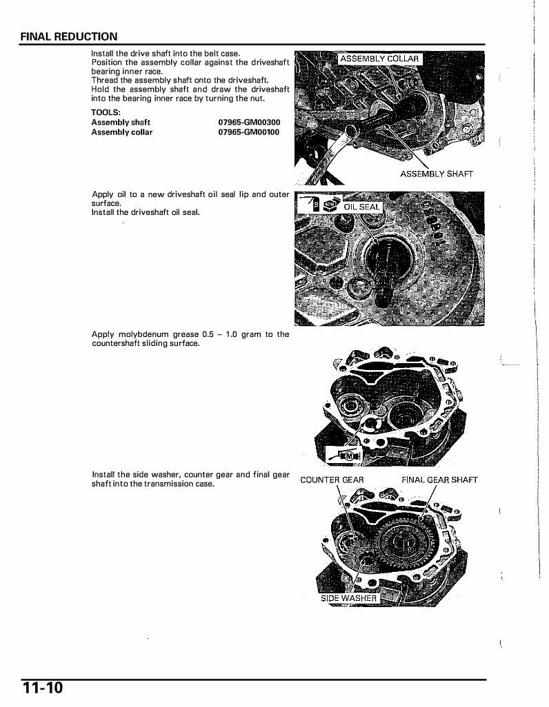
FINAL REDUCTION
1 1 - 1 0
Install the drive shaft into the belt case. Position the assembly collar against the d riveshaft bearing inner race. Thread the assembly shaft onto the driveshaft. Hold the assembly shaft and draw the driveshaft into the bearing inner race by turning the nut. TOOLS: Assembly shaft Assembly collar
07965-GM00300 07965-GM00100
Apply oil to a new driveshaft oi l seal l ip and outer surface. Install the driveshaft ail seal.
Apply molybdenum grease 0.5 - 1 .0 gram to the countershaft sliding surface.
Install the side washer, counter gear and final gear shaft into the transmission case. COUNTER GEAR

Install the countershaft i nto the transmission case. Install the thrust washers onto the countershaft and final gear shaft.
Apply sealant to the transmission case mating surface as shown.
Install the dowel pins. Apply molybdenum grease 0.5 - 1 .0 gram to the countershaft sliding surface. Apply molybdenum grease 0.3 - 0.5 gram to the final gear shaft sliding surface.
Install the transmission case.
FINAL REDUCTION
COUNTER SHAFT
1 1 - 1 1

FINAL REDUCTION
1 1 - 1 2
Install the clamp, bolts and tighten them i n a crisscross pattern in two or three steps.
Install the air cleaner housing and tighten the bolt securely. Install the engine breather drain hose into the clamp. Install the brake cable through the cable holder. Install the following: - Rear brake (page 1 5-6) - Rear wheel (page 1 5-4) - Clutch/driven pulley (page 1 0-18)
Fi l l the final reduction with the recommended final reduction oil (page 1 1 -5).
1 2. ALTERNATOR/STARTER
COMPONENT LOCATIONS························· 12-2 ALTERNATOR/STARTER·····························12-4
SERVICE INFORMATION ···························· 12-3
I
Ill
1 2-1
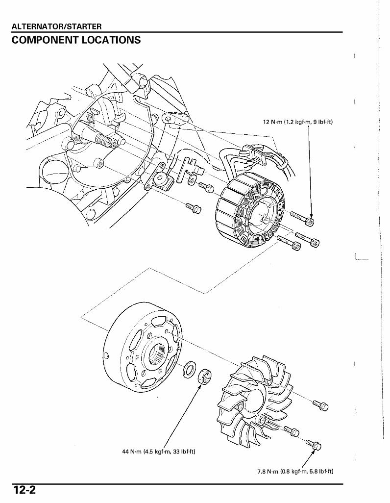
ALTERNATOR/STARTER
COMPONENT LOCATIONS
1 2 N·m ( 1 .2 1cgf·m, 9 lbf.ft)
44 N·m (4.5 kgf·m, 33 lbf.ft)
7.8 N·m (0.8 kgf·m, 5.8 lbf.ft)
1 2-2

SERVICE INFORMATION
GENERAL
ALTERNATOR/STARTER
• Always turn the ignition switch to "OFP' before servicing the alternator/starter. The a lternator/starter could suddenly start when the ignition switch is turned to "ON", causing serious injury.
• This section covers the removal and installation of the flywheel, alternator/starter and ignition pulse generator. • These services can be done with the engine installed i n the frame. • Refer to page 16-8 for alternator/starter inspection.
TORQUE VALUES
Flywheel nut Stator bolts Radiator cooling fan bolt
TOOLS
Universal holder 07725-0030000
44 N·m (4.5 kgf·m, 33 lbf.ft) 12 N·m (1.2 kgf·m, 9 lbf.ft) 7.8 N·m (0.8 kgf·m, 5.8 lbf.ft)
Flywheel puller 07733-0010000
or 07933-0010000 (U.S.A. only)
1 2-3
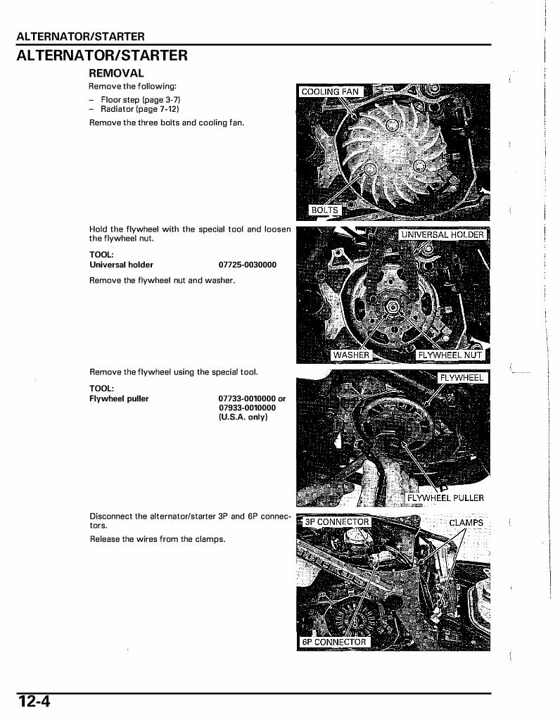
ALTERNATOR/STARTER
ALTERNATOR/STARTER
REMOVAL
1 2-4
Remove the following: - Floor step (page 3-7) - Radiator (page 7-12) Remove the three bolts and cooling fan.
Hold the flywheel with the special tool and loosen the flywheel nut. TOOL: Universal holder 07725-0030000
Remove the flywheel nut and washer.
Remove the flywheel using the special tool.
TOOL: Flywheel puller 07733-0010000 or
07933-0010000 (U.S.A. only)
Disconnect the alternator/starter 3P and 6P connec- "r�coNNEcTOR tors. I Release the wires from the clamps.

Remove the wire band from the water pump stay. Remove the grommet from the crankcase groove. Remove the two bolts, clamp and ignition pulse generator. Remove the three bolts and stator.
Remove the woodruff key from the crankshaft. INSTALLATION Clean any oi l from the tapered portion of the crankshaft and flywheel. Install the woodruff key in the crankshaft key groove.
Install the stator and tighten the bolts to the specified torque.
TORQUE: 12 N·m (1.2 kgf·m, 9 lbf·ft) Install the grommet to the crankcase groove properly. Install the ignition- pulse generator and wire clamp properly as shown. Tighten the bolts securely. Route the alternator/sfarter wires under the guide of the stator base. Install the wire band to the water pump stay.
Route and clamp the alternator/starter wire properly (page 1-1 5).
Connect the alternator/starter 3P and 6P connectors.
ALTERNATOR/STARTER
1 2-5
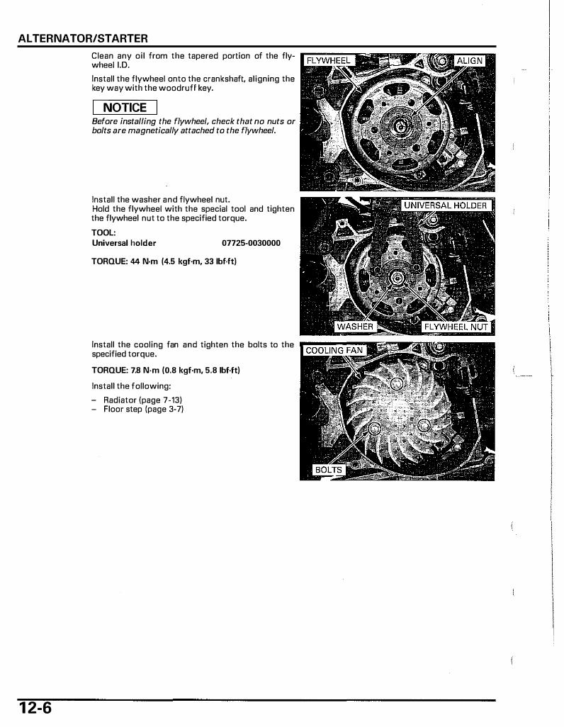
ALTERNATOR/STARTER
1 2-6
Clean any oi l from the tapered portion of the flywheei i.D. Install the flywheel onto the crankshaft, aligning the key way with the woodruff key.
I NOTICE I Before installing the flywheel, check that no nuts or bolts are magnetically attached to the flywheel.
Install the washer and flywheel nut. Hold the flywheel with the special tool and tighten the flywheel nut to the specified torque. TOOL: Universal holder 07725-0030000
TORQUE: 44 N-m (4.5 kgf-m, 33 lbf·ft)
Install the cooling fan and tighten the bolts to the specified torque. TORQUE: 7.8 N-m (0.8 kgf·m, 5.8 lbf·ft)
Install the following: - Radiator (page 7-13) - Floor step (page 3-7)

1 3 . CRAN KSHAFT/PI STON/CYLINDER
COMPONENT LOCATIONs ......................... 13-2
SERVICE INFORMATION ···························· 13-3
TROUBLESHOOTING·································· 13-4
CRANKCASE SEPARATION·························13-5
CRANKSHAFT /PISTON························ ········13-5
CRANKCASE ASSEMBLY ··························13-11
1 3- 1
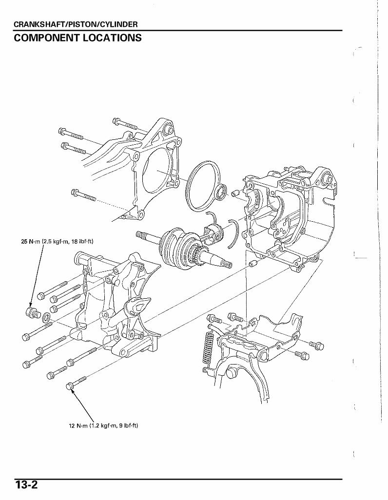
CRANKSHAFT /PISTON/CYLINDER
COMPONENT LOCATIONS
1 3-2
12 N·m .2 kgf·m, 9 lbf.ft)
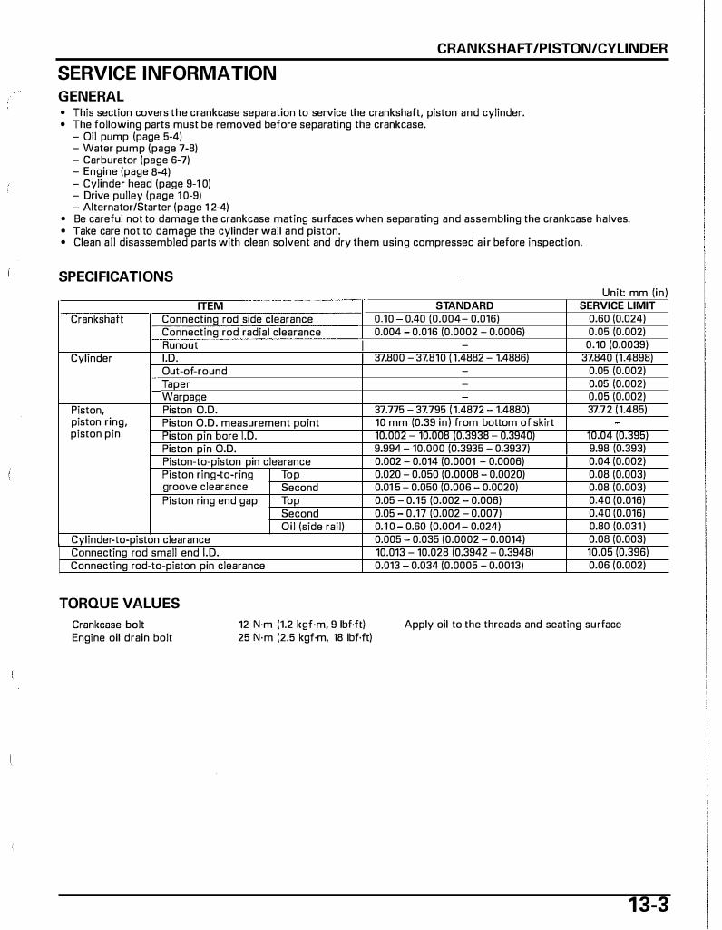
CRANKSHAFT /PISTON/CYLINDER
SERVICE INFORMATION
GENERAL • This section covers the crankcase separation to service the crankshaft, piston and cylinder. • The following parts must be removed before separating the crankcase.
- Oil pump (page 5-4) - Water pump (page 7-8) - Carburetor (page 6-7) - Engine (page 8-4) - Cylinder head (page 9-1 0) - Drive pulley (page 1 0-9) - Alternator/Starter (page 1 2-4)
• Be careful not to damage the crankcase mating surfaces when separating and assembling the crankcase halves. • Take care not to damage the cylinder wall and piston. • Clean al l disassembled parts with clean solvent and dry them using compressed a ir before inspection.
SPECIFICATIONS
ITEM Crankshaft Connecting rod side clearance
Connecting rod radial clearance Runout I
Cylinder I.D. I Out-of-round Taper Warpage
Piston, Piston 0.0. piston ring, Piston O.D. measurement point piston pin Piston pin bare 1.0.
Piston pin O.D. Piston-to-piston pin clearance Piston ring-to-ring Top groove clearance Second Piston ring end gap Top
Second Oil (side rail)
Cylinder-to-piston clearance Connecting rod small end I. D. Connecting rod-to-piston pin clearance
TORQUE VALUES
Crankcase bolt Engine oil drain bolt
12 N·m (1.2 kgf·m, 9 lbf·ft) 25 N·m (2.5 kgf·m, 18 lbf·ft)
Unit· mm (in) STANDARD SERVICE LIMIT
0.10 0.40 (0.004- 0.016) 0.60 (0.024) 0.004 - 0.016 (0,0002 - 0.0006) 0.05 (0.002)
- 0.10 (0.0039) 37.800 - 37.810 ( 1.4882 - 1.4886) 37.840 (1.4898)
- 0.05 (0.002) - 0.05 (0.002)
0.05 (0.002) 37.775 - 37.795 ( 1.4872 - 1.4880) 37.72 (1.485) 10 mm (0.39 in) from bottom of skirt 10.002 - 10.008 (0.3938 - 0.3940) 10.04 (0.395) 9.994 - 10.000 (0.3935 - 0.3937) I 9.98 (0.393) 0.002 - 0.014 (0.0001 - 0.0006) I 0.04 (0.002) 0.020 - 0.050 (0.0008 - 0.0020) 0.08 (0.003) 0.01 5 - 0.050 (0.006 - 0.0020) 0.08 (0.003) 0.05 - 0.15 (0.002 - 0.006) 0.40 (0.016) 0.05 0.17 (0.002 - 0.007) 0.40 (0.016) 0.1 0 - 0.60 (0.004- 0.024) 0.80 (0.031 ) 0.005 0.035 (0.0002 - 0.0014) 0.08 (0.003) 10.013 - 10.028 (0.3942 - 0.3948) 10.05 (0.396) 0.013 0.034 (0.0005 - 0.0013) 0.06 (0.002)
Apply oil to the threads and seating surface
1 3-3
CRANKSHAFT /PISTON/CYLINDER
TROUBLESHOOTING Compression too low, hard starting or poor performance at low speed • Worn, stuck or broken piston ring • Worn or damaged cylinder and piston • Cylinder head/valve problem (page 9-3)
Compression too high, overheating or knocking • Excessive carbon build-up on piston head or on combustion chamber Excessive smoke • Worn cylinder, piston or piston ring • Improper installation of piston rings • Scored or scratched piston or cylinder wall • Cylinder head/valve problem (page 9-3)
Abnormal noise • Worn piston pin or piston pin hole • Worn connecting rod small end • Worn cylinder, piston or piston rings • Worn crankshaft bearing • Worn connecting rod big end bearing
1 3-4

CRANKSHAFT /PISTON/CYLINDER
CRANKCASE SEPARATION Remove the engine from the frame (page 8-4).
Remove the following: - Cylinder head/cam chain (page 9-10) - Oil pump (page 5-41 - Drive pulley (page 10-9)
Remove the four bolts and belt case. Remove the rubber seal. Remove the four bolts and center stand from the crankcase.
Remove the drain bolt and sealing washer. Loosen the crankcase bolts in a crisscross pattern in twa or three steps. Remove the crankcase bolts.
Be careful not to Place the front crankcase facing down and separate damage the crank- the front and rear crankcase halves.
case mating sur-face.
Remove the dowel pins and ail seal. Clean any sealant from the crankcase mating sur- · DOWEL PINS face.
CRANKSHAFT /PISTON
CRANKSHAFT REMOVAL Separate the front and rear crankcase halves. Remove the crankshaft and piston from the front crankcase. Remove the set rings.
1 3-5
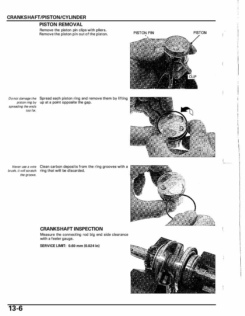
CRANKSHAFT /PISTON/CYLINDER
PISTON REMOVAL Remove the piston pin clips with pliers. Remove the piston pin out of the piston.
Do not damage the Spread each piston ring and remove them by lifting piston ring by up at a point opposite the gap.
spreading the ends too far.
Never use a wire Clean carbon deposits from the ring grooves with a brush, it will scratch ring that will be discarded.
the groove.
1 3-6
CRANKSHAFT INSPECTION Measure the connecting rod big end side clearance with a feeler gauge. SERVICE LIMIT: 0.60 mm (0.024 in)
PISTON PIN PISTON
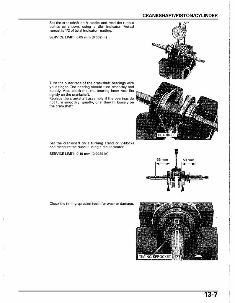
Set the crankshaft on V-blocks and read the runout points as shown, using a dial indicator. Actual run out is 1/2 of total indicator reading. SERVICE LIMIT: 0.05 mm (0.002 in)
Turn the outer race of the crankshaft bearings with your finger. The bearing should turn smoothly and quietly. Also check that the bearing inner race fits tightly on the crankshaft. Replace the crankshaft assembly if the bearings do not turn smoothly, quietly, or if they fit loosely on the crankshaft.
Set the crankshaft on a turning stand or V-blocks and measure the runout using a dial indicator. SERVICE LIMIT: 0.10 mm (0.0039 in)
Check the timing sprocket teeth for wear or damage.
CRANKSHAFT /PISTON/CYLINDER
55 mm 50 mm
1 3-7
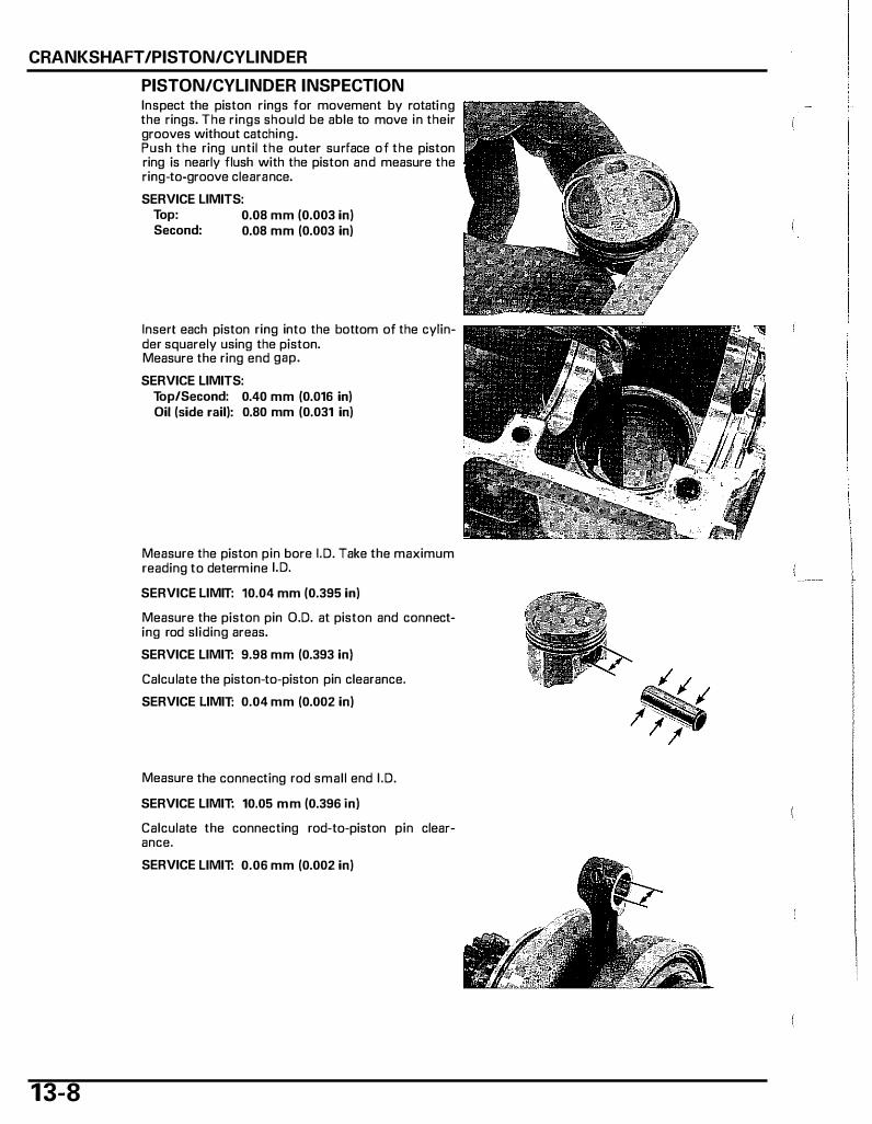
CRANKSHAFT /PISTON/CYLINDER
1 3-8
PISTON/CYLINDER INSPECTION Inspect the piston rings for movement by rotating the rings. The rings should be able to move in their grooves without catching. Push the ring until the outer surface of the piston ring is nearly flush with the piston and measure the ring-to-groove clearance. SERVICE LIMITS:
Top: 0.08 mm (0.003 in) Second: 0.08 mm (0.003 in)
Insert each piston ring into the bottom of the cylinder squarely using the piston. Measure the ring end gap. SERVICE LIMITS:
Top/Second: 0.40 mm (0.016 in) Oil (side rail): 0.80 mm (0.031 in)
Measure the piston pin bore I. D. Take the maximum reading to determine I. D.
SERVICE LIMIT: 10.04 mm (0.395 in)
Measure the piston pin O.D. at piston and connecting rod sliding areas. SERVICE LIMIT: 9.98 mm (0.393 in)
Calculate the piston-to-piston pin clearance. SERVICE LIMIT: 0.04 mm (0.002 in)
Measure the connecting rod small end I . D.
SERVICE LIMIT: 10.05 mm (0.396 in)
Calculate the connecting rod-to-piston pin clearance. SERVICE LIMIT: 0.06 mm (0.002 in)
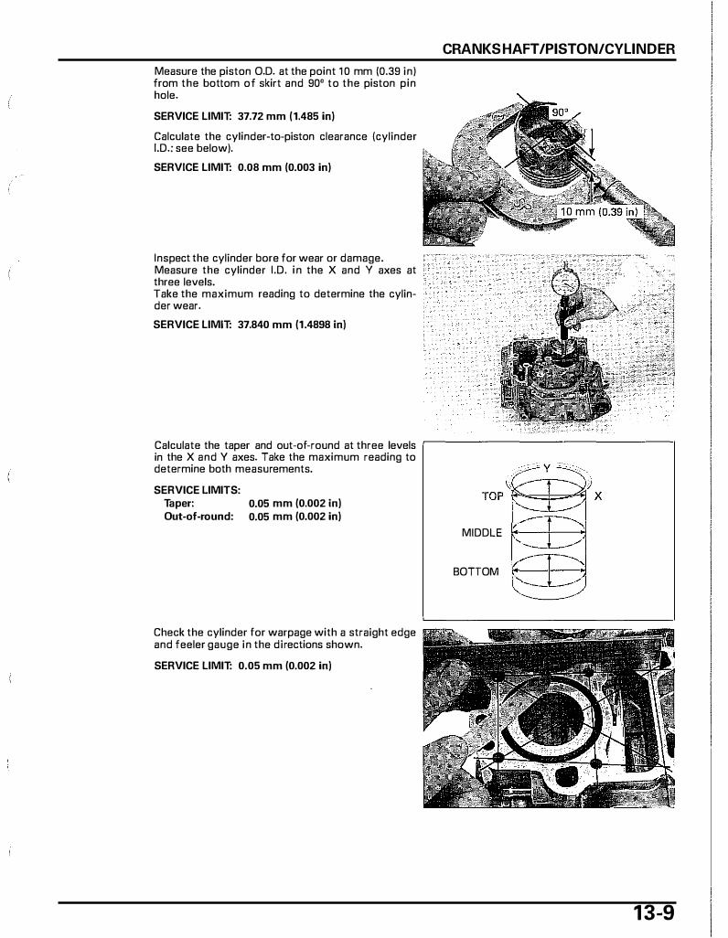
Measure the piston O.D. at the point 1 0 mm (0.39 in) from the bottom of skirt and 90° to the piston pin hole. SERVICE LIMIT: 37.72 mm (1.485 in)
Calculate the cylinder-to-piston clearance {cylinder I.D.: see below). SERVICE LIMIT: 0.08 mm (0.003 in)
Inspect the cylinder bore for wear or damage. Measure the cylinder I.D. in the X and Y axes at three levels. Take the maximum reading to determine the cylinder wear. SERVICE LIMIT: 37.840 mm (1.4898 in)
CRANKSHAFT /PISTON/CYLINDER
Calculate the taper and out-of-round at three levels ,--------------------, in the X and Y axes. Take the maximum reading to determine both measurements. SERVICE LIMITS:
Taper: Out-of-round:
0.05 mm (0.002 in) 0.05 mm (0.002 in)
Check the cylinder for warpage with a straight edge and feeler gauge in the directions shown. SERVICE LIMIT: 0.05 mm (0.002 in)
MIDDLE
BOTTOM
1 3-9
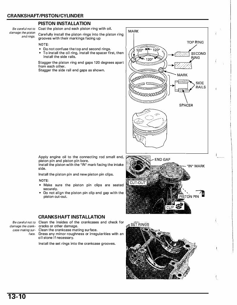
CRANKSHAFT /PISTON/CYLINDER
PISTON INSTALLATION Be careful not to Coat the piston and each piston ring with oil.
damage the piston Carefully install the piston rings into the piston ring and rings. grooves with their markings facing up
NOTE: • Do not confuse the top and second rings. • To install the oil ring, install the spacer first, then
install the side rails. Stagger the piston ring end gaps 1 20 degrees apart from each other. Stagger the side rail end gaps as shown.
Apply engine oil to the connecting rod small end, piston pin and piston pin bore. Install the piston with the "IN" mark facing the intake side. Install the piston pin and new piston pin clips. NOTE: • Make sure the piston pin clips are seated
securely. • Do not align the piston pin clip end gap with the
piston cut-out.
CRANKSHAFT INSTALLATION Be careful not to Clean the insides of the crankcases and check for
damage the crank- cracks or other damage. case mating sur- Clean the crankcase mating surface.
1 3- 1 0
face. Dress any minor roughness or irregularities with an oil stone if necessary. Install the set rings into the crankcase grooves.
MARK
"IN" MARK

Apply engine ail to the connecting rod big end bearing (3 cm3), crankshaft main journal bearings (2 cm3 each), cylinder wall, piston and piston ring outer surface. Install the piston with the " IN" mark facing the intake side while compressing the piston rings with your fingers. Align the crankshaft bearing g rooves with the set rings.
I NOTICE I While installing the piston, being careful not to damage the top surface of the cylinder, especially around the cylinder bore.
CRANKCASE ASSEMBLY Apply oil to a new crankshaft oil seal lip and outer surface. Install the crankshaft oil seal until it is flush with the crankcase surface. Install the dowel pins into the front crankcase.
Apply sealant to the rear crankcase mating surface as shown.
Install the rear crankcase aver the front crankcase.
13-1 1
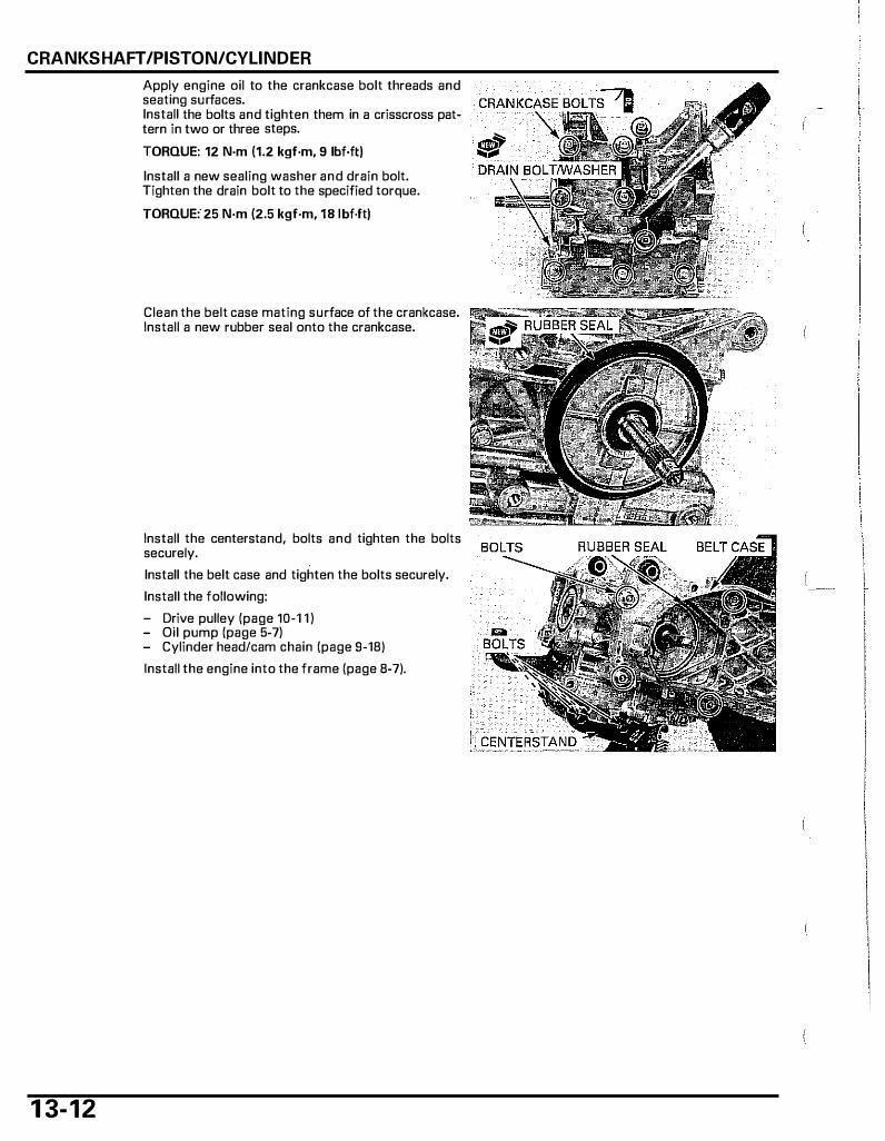
CRANKSHAFT /PISTON/CYLINDER
1 3- 1 2
Apply engine oil to the crankcase bolt threads and seating surfaces. Install the bolts and tighten them in a crisscross pattern in two or three steps. TORQUE: 12 N·m (1.2 kgf·m, 9 lbf·ft) Install a new sealing washer and drain bolt. Tighten the drain bolt to the specified torque. TORQUE: 25 N·m (2.5 kgf·m, 18 lbf·ft)
Clean the belt case mating surface of the crankcase. Install a new rubber seal onto the crankcase.
Install the centerstand, bolts and tighten the bolts securely. Install the belt case and tighten the bolts securely. Install the following: - Drive pulley (page 10-1 1 ) - Oil pump (page 5-7) - Cylinder head/cam chain (page 9-18) Install the engine into the frame (page 8-7).
14. FRONT WHEEL/BRAKE/SUSPENSION/STEERING
COMPONENT LOCATIONs . . . . . . . . . . . . . . . . . . . . . . . . . 1 4-2 FRONT BRAKE . . . . . . . . . . . . . . . . . . . . . . . . . . . . . . . . . . . . . . . . . .. . 14-1 1
SERVICE INFORMATION . . . . . . . . . . . . . . . . . . . . . . . . . . . . 14-3 FORK . . . . . . . . . . . . . . . . . . . . . . . . . . . . . . . . . . . . . . . . . . . . . . . . . . . . . . . . . . . 1 4-15
TROUBLESHOOTING . . . . . . . . . . . . . . . . . . . . . . . . . . . . . . . . . . 14-6 HANDLEBAR . . . . . . . . . . . . . . . . . . . . . . . . . . . . . . . . . . . . . . . . . . . . . . . 14-19
FRONT WHEEL . . . . . . . . . . . . . . . . . . . . . . . . . . . . . . . . . . . . . . . . . . . . 14-7 STEERING STEM . . . . . . . . . . . . . . . . . . . . . . . . . . . . . . . . . . . . . . . . 14-23
I ..
1 4-1

FRONT WHEEl/BRAKE/SUSPENSION/STEERING
COMPONENT LOCATIONS
44 N·m (4.5 kgf·m, 33 lbf.ft) 42 N·m (4.3 kgf·m, 31 lbf.ft)
1 4-2
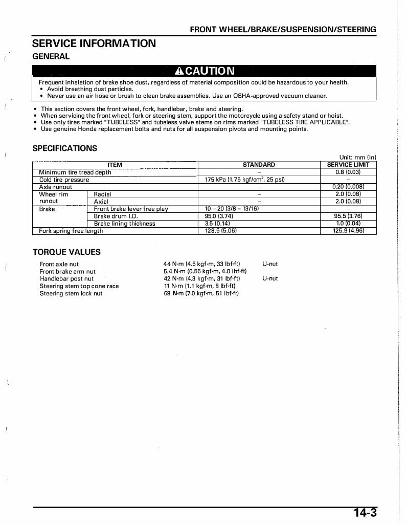
SERVICE INFORMATION
GENERAL
FRONT WHEEL/BRAKE/SUSPENSION/STEERING
A CAUTIO N Frequent inhalation of brake shoe dust, regardless of material composition could be hazardous to your health. • Avoid breathing dust particles. • Never use an air hose or brush to clean brake assemblies. Use an OSHA-approved vacuum cleaner.
• This section covers the front wheel, fork, handlebar, brake and steering. • When servicing the front wheel, fork or steering stem, support the motorcycle using a safety stand or hoist. • Use only tires marked "TUBELESS" and tubeless valve stems on rims marked "TUBELESS TIRE APPLICABLE". • Use genuine Honda replacement bolts and nuts for all suspension pivots and mounting points.
SPECIFICATIONS
ITEM STANDARD Minimum tire tread depth -
Cold tire pressure 175 kPa (1.75 kgf/cm', 25 psi) Axle runout Wheel rim Radial -
run out Axial -
Brake Front brake lever free play 10 - 20 (3/8 - 13/16) Brake drum J .D. Brake lining thickness
Fork spring free length
TORQUE VALUES
Front axle nut Front brake arm nut Handlebar post nut Steering stem top cone race Steering stem lock nut
I 95.0 (3.74) I 3.5 (0.14)
128.5 (5.06)
44 N·m (4.5 kgf·m, 33 lbf.ft) 5.4 N·m (0.55 kgf·m, 4.0 l bf.ft) 42 N·m (4.3 kgf·m, 31 lbf·ft) 11 N·m (1.1 kgf·m, 8 lbf·ft) 69 N·m (7.0 kgf·m, 51 l bf·ft)
U-nut
U-nut
Unit" mm (in) SERVICE LIMIT
0.8 (0.03) -
0.20 (0.008) 2.0 (0.08) 2.0 (0.08)
-
95.5 (3.76) 1.0 (0.04)
125.9 (4.96)
1 4-3
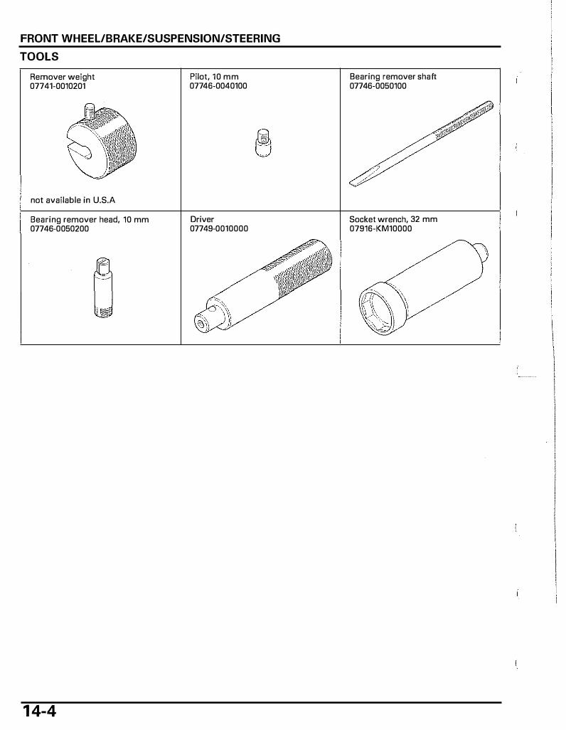
FRONT WHEEL/BRAKE/SUSPENSION/STEERING
TOOLS
Remover weight 07741-0010201
not available in U.S.A
Bearing remover head, 10 mm 07746-0050200
1 4-4
Pilot, 10 mm 07746-0040100
Driver 07749-0010000
Bearing remover shaft 07746-0050100
Socket wrench, 32 mm 07916-KM10000
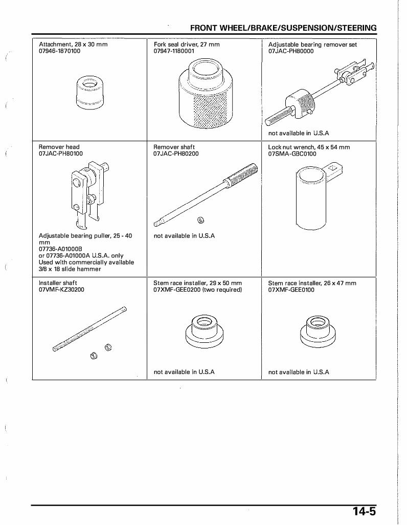
Attachment, 28 x 30 m m 07946-1870100
Remover head 07JAC-PH80100
Adjustable bearing puller, 25 - 40 mm 07736-A01000B or 07736-A01000A U.S.A. only Used with commercial ly available 3/8 x 18 slide hammer
Installer shaft 07VM F-KZ30200
FRONT WHEEL/BRAKE/SUSPENSION/STEERING
Fork seal driver, 27 mm 07947-1180001
Remover shaft 07JAC-PH80200
not available in U.S.A
Stem race installer, 29 x 50 mm 07XMF-GEE0200 (two required)
not available in U.S.A
Adjustable bearing remover set 07 JAC-PH80000
not available in U.S.A
Lock nut wrench, 45 x 54 mm 07SMA-GBC0100
__ ,,._,.__," <l>/
�� ,
Stem race installer, 26 x 47 mm 07XMF·GEE0100
not available in U.S.A
1 4-5
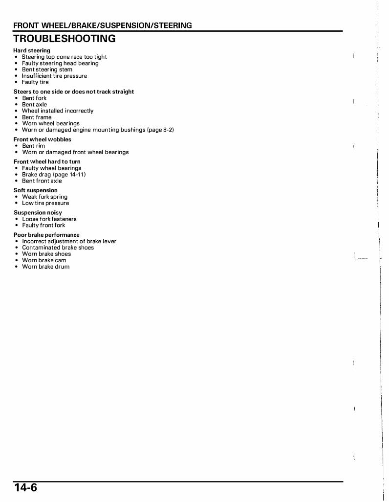
FRONT WHEEL/BRAKE/SUSPENSION/STEERING
TROUBLESHOOTING Hard steering • Steering top cone race too tight • Fau lty steering head bearing • Bent steering stem • Insufficient tire pressure • Faulty tire
Steers to one side or does not track straight • Bent fork • Bent axle • Wheel installed incorrectly • Bent frame • Worn wheel bearings • Worn or damaged engine mounting bushings (page 8-2)
Front wheel wobbles • Bent rim • Worn or damaged front wheel bearings
Front wheel hard to turn • Faulty wheel bearings • Brake drag (page 14-1 1 ) • Bent front axle
Soft suspension • Weak fork spring • Low tire pressure
Suspension noisy • Loose fork fasteners • Faulty front fork
Poor bral(e performance • Incorrect adjustment of brake lever • Contaminated brake shoes • Worn brake shoes • Worn brake cam • Worn brake drum
1 4-6
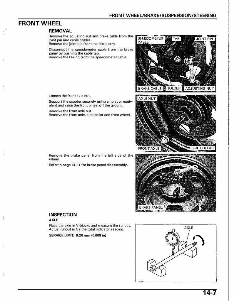
FRONT WHEEL/BRAKE/SUSPENSION/STEERING
FRONT WHEEL
REMOVAL Remove the adjusting nut and brake cable from the joint pin and cable holder. Remove the joint pin from the brake arm.
Disconnect the speedometer cable from the brake panel by pushing the cable tab. Remove the 0-ring from the speedometer cable.
Loosen the front axle nut.
Support the scooter securely using a hoist or equivalent and raise the front wheel off the ground.
Remove the front axle nut. Remove the front axle, side collar and front wheel.
Remove the brake panel from the left side of the wheel.
Refer to page 14-1 1 for brake panel disassembly.
INSPECTION AXLE
Place the axle in V-blocks and measure the runout. Actual runout is 1/2 the total indicator reading.
SERVICE LIMIT: 0.20 mm (0.008 in)
1 4-7
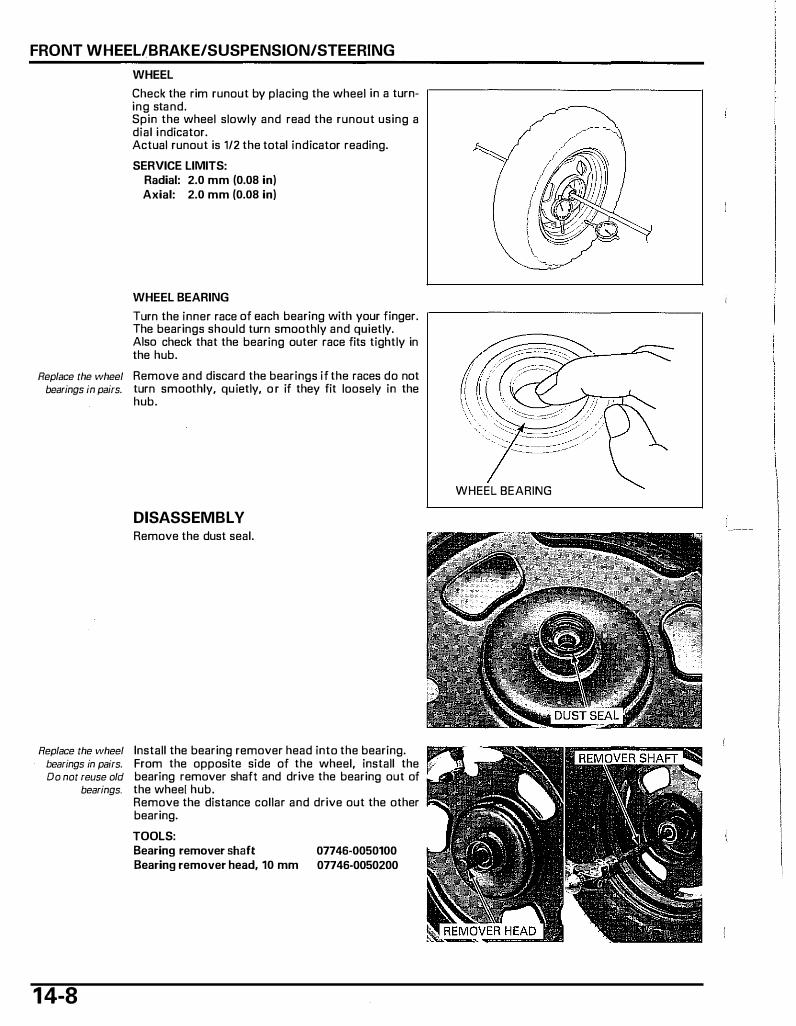
FRONT WHEEL/BRAKE/SUSPENSION/STEERING
WHEEL
Check the rim runout by placing the wheel in a turn- ,--------------------, ing stand. Spin the wheel slowly and read the runout using a dial indicator. Actual runout is 1/2 the total indicator reading.
SERVICE LIMITS: Radial: 2.0 mm (0.08 in) Axial: 2.0 mm (0.08 in)
WHEEL BEARING
Turn the inner race of each bearing with your finger. ,--------------------, The bearings should turn smoothly and quietly. Also check that the bearing outer race fits tightly in the hub.
Replace the wheel Remove and discard the bearings if the races do not bearings in pairs. turn smoothly, quietly, o r if they fit loosely in the
hub.
DISASSEMBLY Remove the dust seal.
Replace the wheel Install the bearing remover head into the bearing. bearings in pairs. From the opposite side of the wheel, install the Do not reuse old bearing remover shaft and drive the bearing out of
bearings. the whee[ hub.
1 4-8
Remove the distance collar and drive out the other bearing.
TOOLS: Bearing remover shaft Bearing remover head, 10 mm
07746-0050100 07746-0050200
WHEEL BEARING

FRONT WHEEL/BRAKE/SUSPENSION/STEERING
ASSEMBLY
DISTANCE COLLAR
BEARING (6200U)
Pack the new bearing cavities with grease.
Drive a new left bearing (brake drum side) squarely with the sealed side facing up until it is fully seated.
Install the distance collar.
Drive a new right bearing squarely with the sealed side facing up until it is fully seated using the special tools.
TOOLS: Driver Attachment, 28 X 30 mm Pilot, 10 mm
07749-0010000 07946-1870100 07746-0040100
Apply grease to new dust seal lips. Install the dust seal into the left wheel hub until it is flush with the wheel hub.
BEARING (6200U)
1 4-9
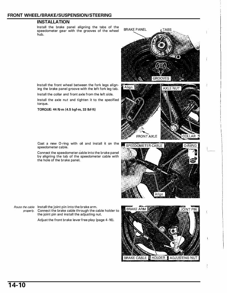
FRONT WHEEl/BRAKE/SUSPENSION/STEERING
INSTAllATION Install the brake panel aligning the tabs of the speedometer gear with the grooves of the wheel hub.
BRAKE PANEL
Install the front wheel between the fork legs align- 111!"'-ing the brake panel g roove with the left fork leg tab.
Install the collar and front axle from the left side.
Install the axle nut and tighten it to the specified torque.
TORQUE: 44 N·m (4.5 l<gf·m, 33 lbf·ft)
Coat a new 0-ring with oil and install it on the speedometer cable.
Connect the speedometer Cable into the brake panel by aligning the tab of the speedometer cable with the hole of the brake panel.
Route the cable Install the joint pin into the brake arm. properly. Connect the brake cable through the cable holder to
the joint pin and install the adjusting nut.
Adjust the front brake lever free play (page 4-16).
1 4- 1 0
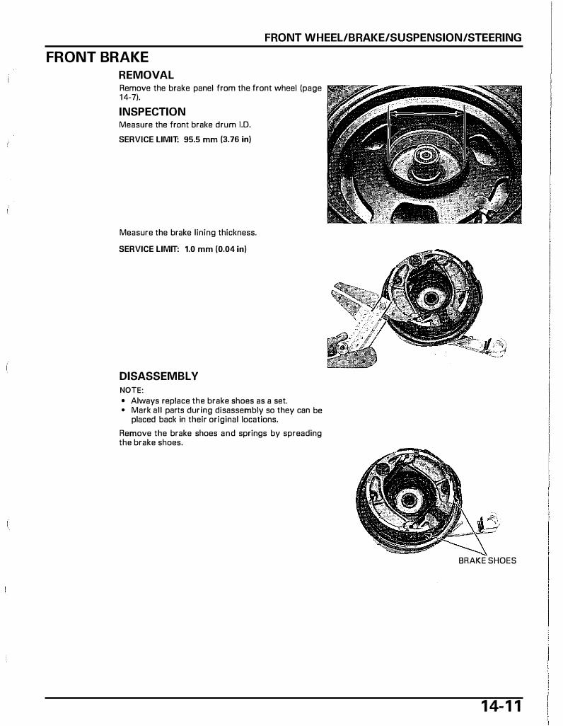
FRONT WHEEL/BRAKE/SUSPENSION/STEERING
FRONT BRAKE
REMOVAL Remove the brake panel from the front wheel (page 1 4-7).
INSPECTION Measure the front brake drum 1.0. SERVICE LIMIT: 95.5 mm (3.76 in)
Measure the brake lining thickness.
SERVICE LIMIT: 1.0 mm (0.04 in)
DISASSEMBLY NOTE: • Always replace the brake shoes as a set. • Mark all parts during disassembly so they can be
placed back in their original locations.
Remove the brake shoes and springs by spreading the brake shoes.
BRAKE SHOES
1 4- 1 1
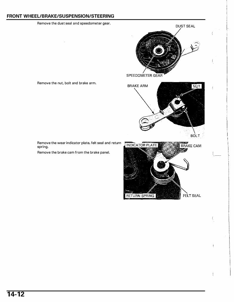
FRONT WHEEL/BRAKE/SUSPENSION/STEERING
1 4- 1 2
Remove the dust seal and speedometer gear.
Remove the nut, bolt and brake arm.
Remove the wear indicator plate, felt seal and return spring.
Remove the brake cam from the brake panel.
DUST SEAL
BRAKE ARM
BOLT

FRONT WHEEL/BRAKE/SUSPENSION/STEERING
ASSEMBLY
FELT SEAL
RETURN SPRING BRAKE ARM
Apply grease to the brake cam. Install the brake cam into the brake panel.
Apply oil to the felt seal and install it to the brake cam.
Install the return spring, aligning its end with the brake panel hole as shown.
Install the wear indicator onto the brake cam by aligning its wide tooth with the wide groove of the brake cam.
SPEEDOMETER GEAR
DUST SEAL
SHOES
1 4- 1 3
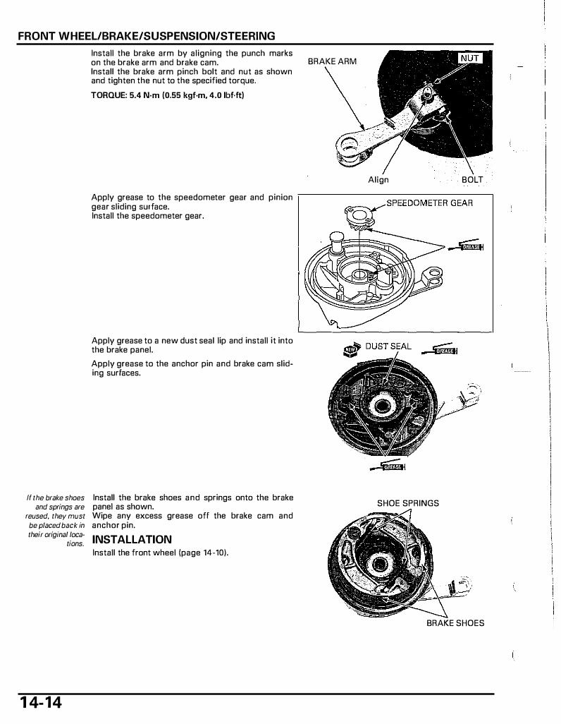
FRONT WHEEL/BRAKE/SUSPENSION/STEERING
If the brake shoes and springs are
reused, they must be placed back in their original loca-
tions.
1 4-14
Install the brake arm by aligning the punch marks on the brake arm and brake cam. Install the brake arm pinch bolt and nut as shown and tighten the nut to the specified torque.
TORQUE: 5.4 N·m (0.55 kgf·m, 4.0 lbf.ft)
Apply grease to the speedometer gear and pinion gear sliding surface. Install the speedometer gear.
Apply grease to a new dust seal lip and install it into the brake panel.
Apply grease to the anchor pin and brake cam sliding surfaces.
Install the brake shoes and springs onto the brake panel as shown. Wipe any excess grease off the brake cam and anchor pin.
INSTALLATION Install the front wheel (page 14-10).
BRAKE ARM
Align BOLT
SHOE SPRINGS
BRAKE SHOES
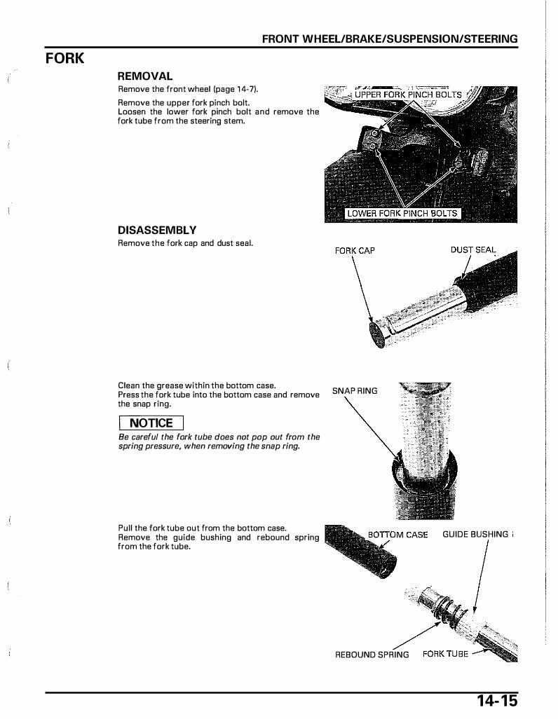
FORK
FRONT WHEEL/BRAKE/SUSPENSION/STEERING
REMOVAL Remove the front wheel (page 1 4-7).
Remove the upper fork pinch bolt. Loosen the lower fork pinch bolt and remove the fork tube from the steering stem.
DISASSEMBL V Remove the fork cap and dust seal.
Clean the grease within the bottom case. Press the fork tube into the bottom case and remove the snap ring.
I NOTICE I Be careful the fork tube does not pop out from the spring pressure, when removing the snap ring.
Pull the fork tube out from the bottom case. Remove the guide bushing and rebound spring from the fork tube.
SNAP RING
GUIDE BUSHING ;
REBOUND SPRING
1 4- 1 5
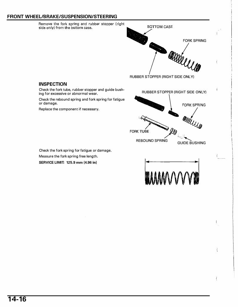
FRONT WHEEL/BRAKE/SUSPENSION/STEERING
1 4- 1 6
INSPECTION Check the fork tube, rubber stopper and guide bushing for excessive or abnormal wear.
Check the rebound spring and fork spring for fatigue or damage.
Replace the component if necessary.
Check the fork spring for fatigue or damage.
Measure the fork spring free length.
SERVICE LIMIT: 125.9 mm (4.96 in)
FORK SPRING
RUBBER STOPPER (RIGHT SIDE ONLY)
RUBBER STOPPER (RIGHT SIDE ONLY)
� l ''"'""" , ,
FORK TUBE � c 1 � "-.._ REBOUND SPRING GUIDE BUSHING
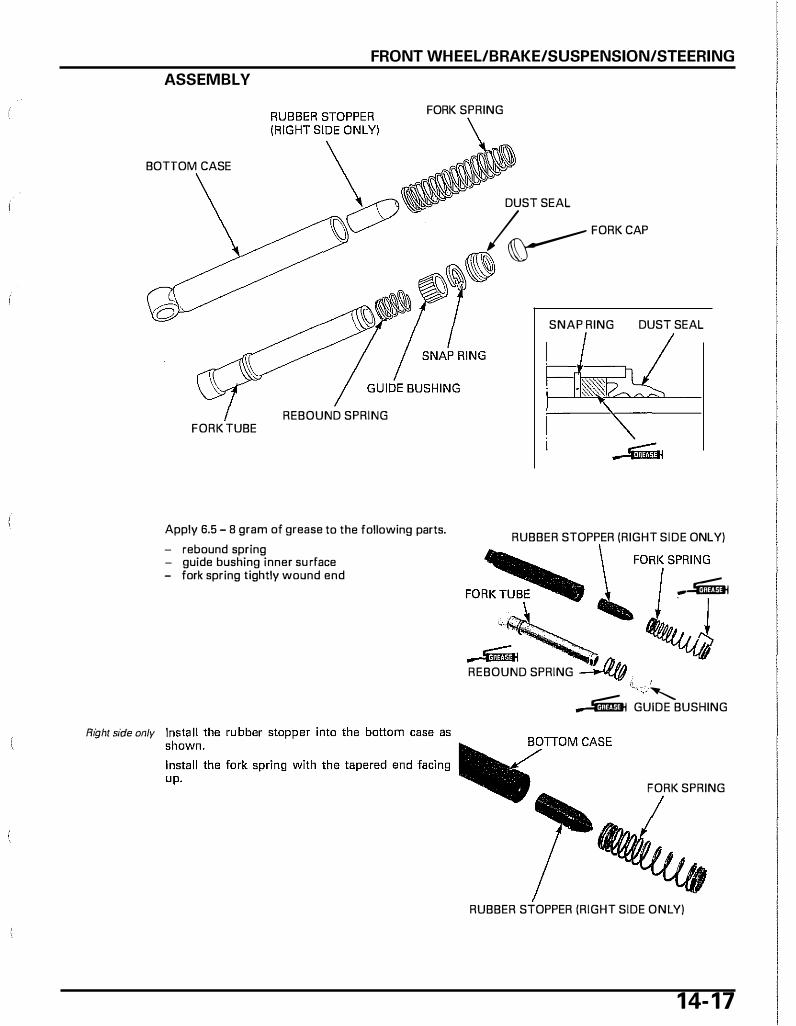
FRONT WHEEL/BRAKE/SUSPENSION/STEERING
ASSEMBLY
FORK SPRING
BOTTOM CASE
Right side only
DUST SEAL � � FORK CAP
[3 , 0
REBOUND SPRING FORK TUBE
Apply 6.5 - 8 gram of grease to the following parts.
- rebound spring - guide bushing inner su rface - fork spring tightly wound end
SNAP RING DUST SEAL
RUBBER STOPPER (RIGHT SIDE ONLY) �.. lFORK SPRING
FOR K TU� -�
_;.,fl .. REBOUND SPRING -"L(f! ! ' -� GUIDE BUSHING
FORK SPRING
RUBBER STOPPER (RIGHT SIDE ONLY)
1 4- 1 7
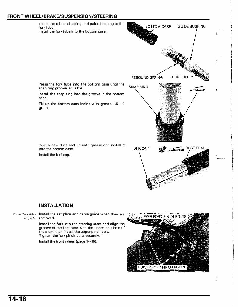
FRONT WHEEL/BRAKE/SUSPENSION/STEERING
Install the rebound spring and guide bushing to the fork tube. Install the fork tube into the bottom case.
Press the fork tube into the bottom case u ntil the snap ring groove is visible.
Install the snap ring into the groove in the bottom case.
Fill up the bottom case inside with grease 1 .5 - 2 gram.
Coat a new dust seal lip with grease and install it into the bottom case.
Install the fork cap.
INSTALLATION
Route the cables Install the set plate and cable guide when they are properly. removed.
1 4- 1 8
Install the fork into the steering stem and align the groove of the fork tube with the upper bolt hole of the stem, then install the upper pinch bolt. Tighten the fork pinch bolts securely.
Install the front wheel I page 14·10).
G U IDE BUSHING
REBOUND FORK TUBE
SNAP RING
� -� DUST SEAL
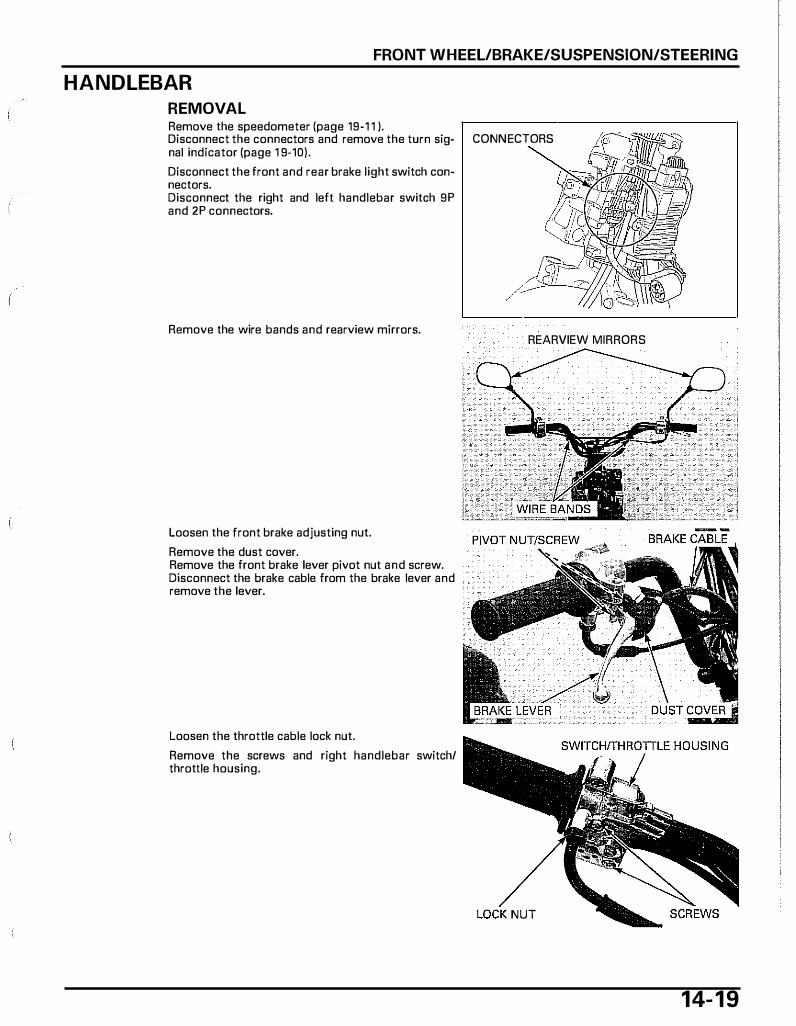
FRONT WHEEL/BRAKE/SUSPENSION/STEERING
HANDLEBAR
REMOVAL Remove the speedometer (page 19-1 1 ). Disconnect the connectors and remove the turn sig- CONNECTORS nal indicator (page 1 9-10).
Disconnect the front and rear brake light switch connectors. Disconnect the right and left handlebar switch 9P and 2P connectors.
Remove the wire bands and rearview mirrors.
Loosen the front brake adjusting nut.
Remove the dust cover. Remove the front brake lever pivot nut and screw. Disconnect the brake cable from the brake lever and remove the lever.
Loosen the throttle cable lock nut.
Remove the screws and right handlebar switch/ throttle housing.
REARVIEW MIRRORS
NUT
14- 1 9
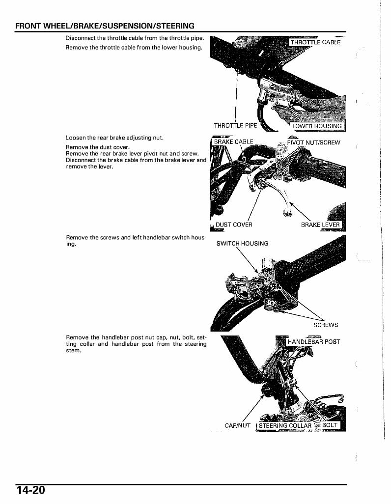
FRONT WHEEL/BRAKE/SUSPENSION/STEERING
1 4-20
Disconnect the throttle cable from the throttle pipe.
Remove the throttle cable from the lower housing.
Loosen the rear brake adjusting nut.
Remove the dust cover. Remove the rear brake lever pivot nut and screw. Disconnect the brake cable from the brake lever and remove the lever.
Remove the screws and left handlebar switch housing.
Remove the handlebar post nut cap, nut, bolt, setting collar and handlebar post from the steering stem.
It DUST COVER
SWITCH HOUSING
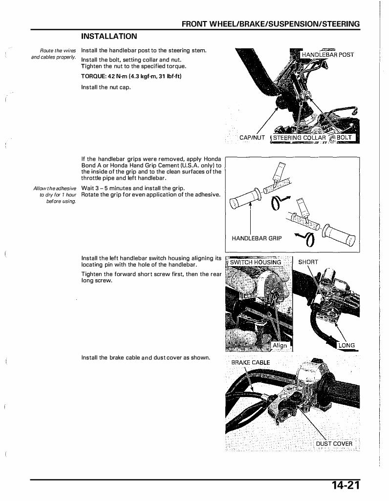
FRONT WHEEL/BRAKE/SUSPENSION/STEERING
INSTALLATION
Route the wires Install the handlebar post to the steering stem. and cables properly. Install the bolt, setting collar and nut.
Tighten the nut to the specified torque.
TORQUE: 42 N·m (4.3 kgf·m, 31 lbf·ft)
Install the nut cap.
If the handlebar grips were removed, apply Honda Bond A or Honda Hand Grip Cement (U.S.A. only) to the inside of the grip and to the clean surfaces of the throttle pipe and left handlebar.
Allow the adhesive Wait 3 - 5 minutes and install the grip. to dry for 1 hour Rotate the grip for even application of the adhesive.
before using.
CAP/NUT
HANDLEBAR GRIP
Install the left handlebar switch housing aligning its �������-:--�:;:�----__J locating pin with the hole of the handlebar.
Tighten the forward short screw first, then the rear long screw.
Install the brake cable and dust cover as shown.
DUST COVER
14-2 1
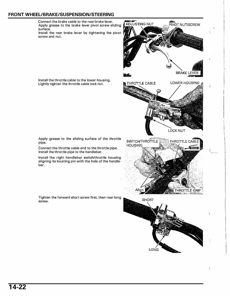
FRONT WHEEL/BRAKE/SUSPENSION/STEERING
1 4-22
Connect the brake cable to the rear brake lever. Apply grease to the brake lever pivot screw sliding surface. Install the rear bral<e lever by tightening the pivot screw and nut.
Install the throttle cable to the lower housing. Lightly tighten the th rottle cable lock nut.
Apply grease to the sliding surface of the throttle pipe.
Connect the throttle cable end to the throttle pipe. Install the throttle pipe to the handlebar.
Install the right handlebar switch/throttle housing aligning its locating pin with the hole of the handlebar.
Tighten the forward short screw first, then rear long screw.

FRONT WHEEL/BRAKE/SUSPENSION/STEERING
Apply grease to the pivot screw sliding surface.
Connect the brake cable to the front brake lever. Install the brake lever by tightening the pivot screw and nut.
Install the dust cover.
Tighten the brake cable lock nut securely.
Route the wires Install the wire bands. and cables properly. Install the rearview mirrors.
PIVOT NUT/SCREW �
REARVIEW MIRRORS
Connect the right and left handlebar switch 9P and illilllli����������i88--l,
2P connectors. Connect the front and rear brake light switch connectors.
Install the turn signal indicator (page 1 9-10) and connect the connectors. Install the speedometer (page 1 9-1 1 ).
Adjust the front and rear brake lever free play (page 4-1 6). Adjust the throttle grip free play (page 4-4).
STEERING STEM
REMOVAL
Remove the following:
- Front wheel (page 1 4-7) - Fork (page 14-15) - Handlebar (page 14-19)
Remove the bolts and front fender.
Remove the stem cover.
STEM COVER
1 4-23

FRONT WHEEL/BRAKE/SUSPENSION/STEERING
Remove the steering stem lock nut using the special tool.
TOOL: Socket wrench, 32 mm 07916-KM10000
Remove the lock washer.
Loosen the top cone race using the special tool.
TOOL: lock nut wrench, 45 X 54 mm 07SMA-GBC0100
Hold the steering stem and remove the steering top cone race.
Remove the upper bearing.
Remove the steering stem and lower bearing.
BEARING REPLACEMENT Always replace the Remove the upper/lower bearing outer races using bearings and races the special tools.
as a set
1 4-24
TOOlS: Not available in U.S.A.
Adjustable bearing remover set 07JAC-PHBOOOO -Remover head 07JAC-PH80100 -Remover shaft -Remover weight
U.S.A. only Adjustable bearing puller, 25 - 40 mm
Slide hammer, 3/8 X 16
07JAC-PH80200 07741-0010201
07736-A010008 or 07736-A01000A Commercially available

FRONT WHEEL/BRAKE/SUSPENSION/STEERING
Install a new lower bearing outer race using the special tools as shown.
TOOLS: Stem race installer, 29 X SO mm 07XMF-GEE0200
(two required) not available in U.S.A.
Installer shaft 07VMF-KZ30200
Install a new upper bearing outer race using the special tools as shown.
TOOLS: Stem race installer, 26 X 47 mm 07XMF-GEE0100
not available in U.S.A.
Stem race installer, 29 X SO mm 07XMF-GEE0200
Installer shaft
not available in U.S.A. 07VMF-KZ30200
Install the steering stem lock nut onto the steering stem to prevent the threads from being damaged when removing the bottom cone race from the steering stem.
Remove the lower bearing inner race with a chisel or equivalent tool, being careful not to damage the steering stem.
Apply grease to a new lower bearing inner race and press it to the steering stem using the special tool.
TOOL: Fork seal driver, 27 mm 07947-1180001
BOTIOM CONE RACE
FORK SEAL
1 4-25

FRONT WHEEL/BRAKE/SUSPENSION/STEERING
1 4-26
INSTALLATION
LOCK NUT STEM COVER
LOCI< WASHER """ � / /1 TOP CONE RACE � �
UPPER BEARING � /
UPPER OUTER RA�-
// .::Jt'§§'&--lr-� / / •" //
STEERING STEM
Fill up each new bearing and inner race with grease ll""...,...,.,...,...,.,�"!ii-� 3 - 5 gram. Install the lower bearing onto the stem. Insert the steering stem into the steering head pipe.
Install the upper bearing and top cone race.
Tighten the steering top cone race to the specified torque using the special tool.
TOOL: Loci< nut wrench, 45 X 54 mm 07SMA·GBC0100
TORQUE: 11 N·m (1 .1 kgf·m, B lbf.ft)
NUT WRENCH
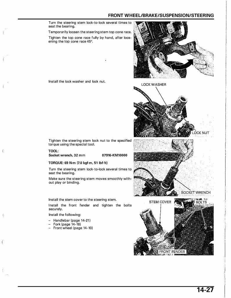
FRONT WHEEL/BRAKE/SUSPENSION/STEERING
Turn the steering stem lock-to-lack several times to seat the bearing.
Temporarily loosen the steering stem top cone race.
Tighten the top cone race fully by hand, after loosening the top cone race 45°.
Install the lock washer and lock nut. LOCI< WASHER
Tighten the steering stem lock nut to the specified �T''" ' ' - - - ,._ torque using the special tool.
TOOL: Socket wrench, 32 mm 07916-KMlOOOO
TORQUE: 69 N·m (7.0 ltgf·m, 51 lbf·ft)
Turn the steering stem lock-to-lock several times to �� ..... ,;.: seat the bearing.
Make sure the steering stem moves smoothly without play or binding.
Install the stem cover to the steering stem.
I nstall the front fender and tighten the bolts securely.
Install the following:
- Handlebar !page 14-21 ) - Fork lpage 14-18) - Front wheel ipage 14-10)
1 4-27
1 5. REAR WHEEL/BRAKE/SUSPEN SION
COMPONENT LOCATIONS························· 15-2 REAR WHEEL················································15-4
SERVICE INFORMATION ···························· 15-3 REAR BRAKE ················································15-4
TROUBLESHOOTING·································· 15-3 REAR SHOCK ABSORBER ···························15-7
El,
1 5- 1
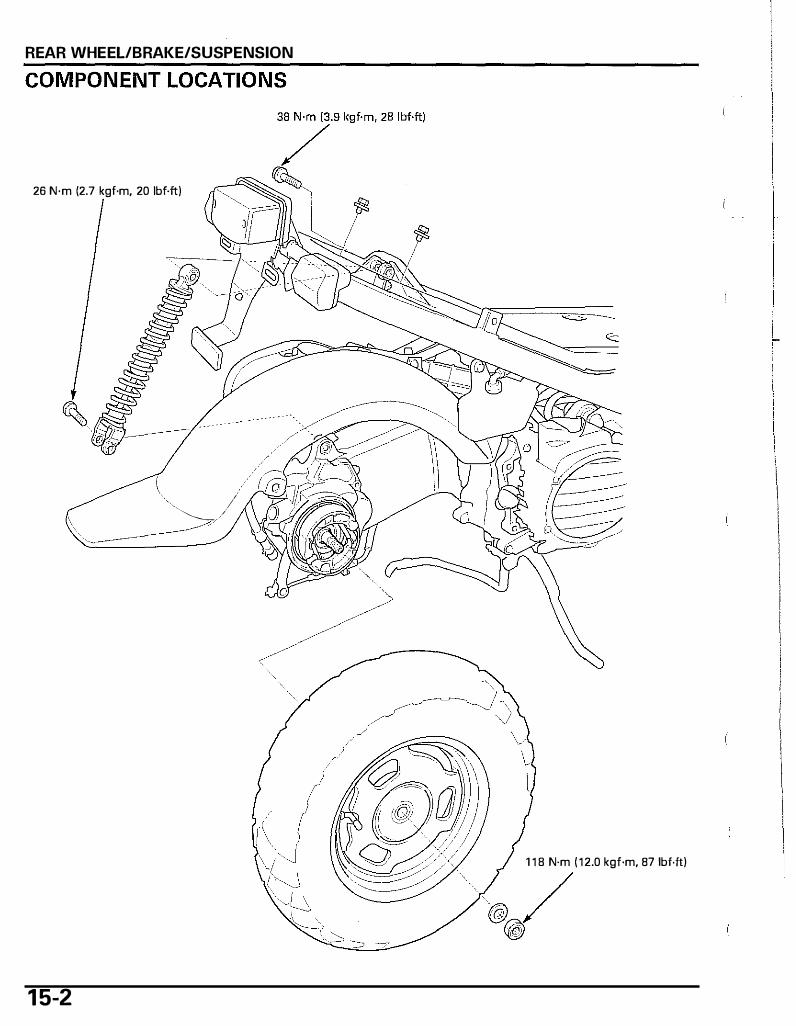
REAR WHEEL/BRAKE/SUSPENSION
26 N·m (2.7 kgf·m, 20 lbf.ft)
\. /
� / \ �
1 5-2
1 1 8 N·m ( 1 2.0 kgf·m, B7 1bf.ft)
@ / �
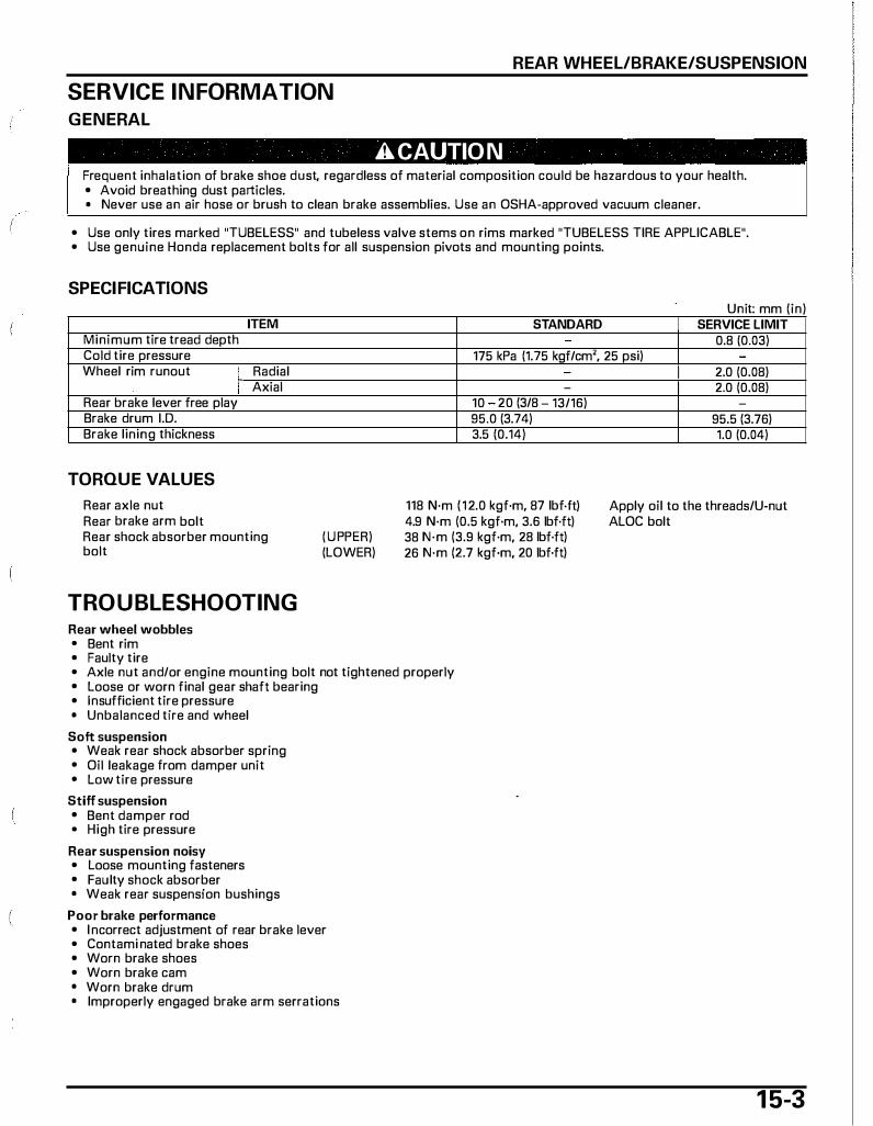
SERVICE INFORMATION
GENERAL
REAR WHEEL/BRAKE/SUSPENSION
A CAUTIO N Frequent inhalation of brake shoe dust, regardless of material composition could be hazardous to your health. • Avoid breathing dust particles. • Never use an air hose or brush to clean brake assemblies. Use an OSHA-approved vacuum cleaner.
• Use only tires marked "TUBELESS" and tubeless valve stems on rims marked "TUBELESS TIRE APPLICABLE". • Use genuine Honda replacement bolts for all suspension pivots and mounting points.
SPECIFICATIONS Unit' mm (in)
ITEM STANDARD SERVICE LIMIT Minimum tire tread depth 0.8 (0.03) Cold tire pressure 175 kPa (1.75 kgf/cm', 25 psi) -
Wheel rim runout I Radial I Axial
Rear brake lever free play Brake drum J.D. Brake lining thickness
TORQUE VALUES
Rear axle nut Rear brake arm bolt Rear shock absorber mounting bolt
TROUBLESHOOTING Rear wheel wobbles • Bent rim • Faulty tire
(UPPER) (LOWER)
-
10 20 (3/8 13/16) 95.0 (3.74) 3.5 (0.14)
118 N·m ( 1 2.0 kgf·m, 87 lbf.ft) 4.9 N·m (0.5 kgf·m, 3.6 lbf·ft) 38 N·m (3.9 kgf·m, 28 lbf·ft) 26 N·m (2.7 kgf·m, 20 lbf·ft)
• Axle nut and/or engine mounting bolt not tightened properly • Loose or worn final gear shaft bearing • Insufficient tire pressure • Unbalanced tire and wheel
Soft suspension • Weak rear shock absorber spring • Oil leakage from damper unit • Low tire pressure
Stiff suspension • Bent damper rod • High tire pressure
Rear suspension noisy • Loose mounting fasteners • Faulty shock absorber • Weak rear suspension bushings
Poor brake performance • I ncorrect adjustment of rear brake lever • Contami nated brake shoes • Worn brake shoes • Worn brake cam • Worn brake drum • Improperly engaged brake arm serrations
I 2.0 (0.08) I 2.0 (0.08)
95.5 (3.76) 1.0 (0.04)
Apply oil to the threads/U-nut ALOC bolt
1 5-3

REAR WHEEL/BRAKE/SUSPENSION
R EAR WHEEL
INSPECTION Check the wheel rim runout using dial i ndicators. Actual runout is 1 /2 the total indicator readings.
SERVICE liMITS: Radial: 2.0 mm (0.08 in) Axial: 2.0 mm (0.08 in)
REMOVAL Place the scooter on its center stand.
Remove the muffler (page 3-9).
Remove the rear axle nut, washer and rear wheel.
INSTALLATION Install the rear wheel onto the final gear shaft, aligning the spline. Install the washer onto the final gear shaft.
Apply oil to the threads and seating surface of the rear axle nut. Tighten the rear axle nut to the specified torque.
TORQUE: 118 N·m {12.0 l<gf·m, 87 lbf·ft)
Install the muffler (page 3-9).
REAR BRAKE Remove the rear wheel (page 1 5-4).
INSPECTION Measure the rear brake drum I. D.
SERVICE liMIT: 95.5 mm (3.76 in)
Measure the brake lining thickness.
SERVICE liMIT: 1.0 mm (0.04 in)
1 5-4
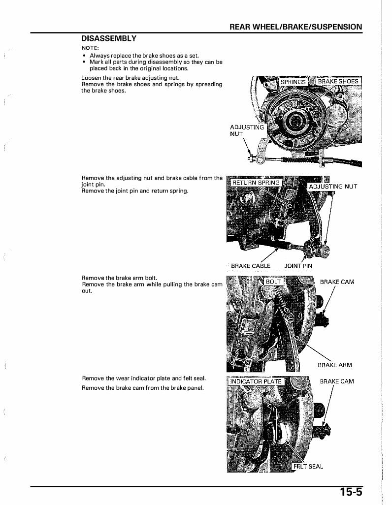
DISASSEMBLY NOTE: • Always replace the brake shoes as a set. • Mark all parts during disassembly so they can be
placed back in the original locations.
Loosen the rear brake adjusting nut. Remove the brake shoes and springs by spreading the brake shoes.
Remove the adjusting nut and brake cable from the joint pin. Remove the joint pin and return spring.
Remove the brake arm bolt. Remove the brake arm while pulling the brake cam out.
Remove the wear indicator plate and felt seal.
Remove the brake cam from the brake panel.
REAR WHEEL/BRAKE/SUSPENSION
NUT
1 5-5
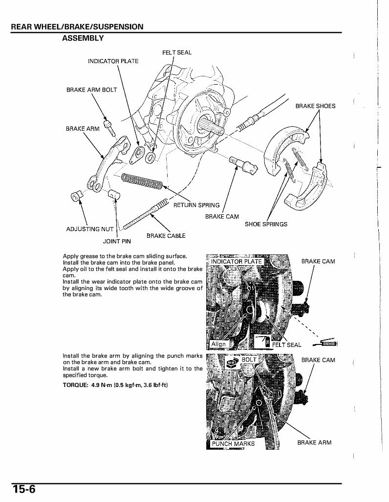
REAR WHEEL/BRAKE/SUSPENSION
1 5-6
ASSEMBLY
FELT SEAL
BRAKE ARM BOLT
JOINT PIN
Apply grease to the brake cam sliding su rface. Install the brake cam into the brake panel. Apply oil to the felt seal and install it onto the brake cam. Install the wear indicator plate onto the brake cam by aligning its wide tooth with the wide groove of the brake cam.
Install the brake arm by aligning the punch marks on the brake arm and brake cam. Install a new brake arm bolt and tighten it to the specified torque.
TORQUE: 4.9 N·m (0.5 kgf·m, 3.6 lbf·ft)
BRAKE SHOES
CAM
BRAKE ARM
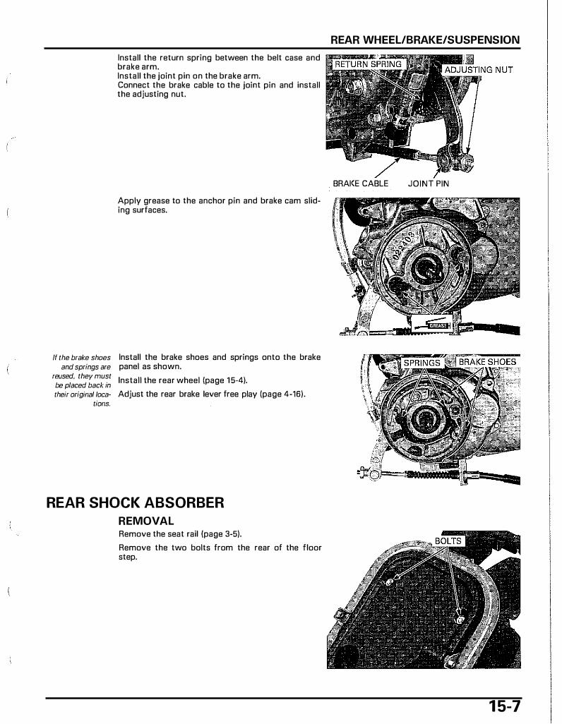
ff the brake shoes and springs are
reused, they must be placed back in their original loca-
tions.
Install the return spring between the belt case and brake arm. Install the joint pin on the brake arm. Connect the brake cable to the joint pin and install the adjusting nut.
Apply grease to the anchor pin and brake cam sliding surfaces.
Install the brake shoes and springs onto the brake panel as shown.
Install the rear wheel (page 1 5-4).
Adjust the rear brake lever free play (page 4-16).
REAR SHOCK ABSORBER
REMOVAL Remove the seat rail (page 3-5).
Remove the two bolts from the rear of the floor step.
REAR WHEEL/BRAKE/SUSPENSION
BRAI<E CABLE JOINT PIN
1 5-7
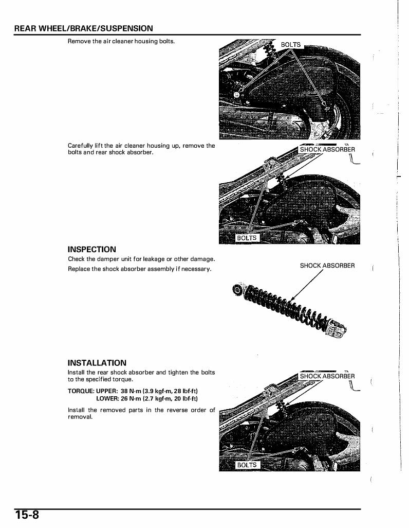
REAR WHEEL/BRAKE/SUSPENSION
1 5-8
Remove the air cleaner housing bolts.
Carefully lift the air cleaner housing up, remove the bolts and rear shock absorber.
INSPECTION Check the damper unit for leakage or other damage.
Replace the shock absorber assembly if necessary.
INSTALLATION Install the rear shocl< absorber and tighten the bolts to the specified torque.
TORQUE: UPPER: 38 N·m (3.9 kgf·m, 28 lbf.ft) lOWER: 26 N·m (2.7 kgf·m, 20 lbf.ft)
Install the removed parts in the reverse order of removal.
�
SHOCK ABSORBER
L
SHOCK ABSORBER
�
SHOCK ABSORBER
\\__
1 6. BATTERY/CHARGING SYSTEM
SYSTEM DIAGRAM····································· 16-2
SERVICE INFORMATION ···························· 16-3
TROUBLESHOOTING·································· 16-5
BATTERY······················································ 16-6
CHARGING SYSTEM INSPECTION ............. 16-7
ALTERNATOR CHARGING COIL ·················16-8
ENGINE CONTROL MODULE (ECM}···········16-9
MAIN RELAY···············································16-11
1 6- 1
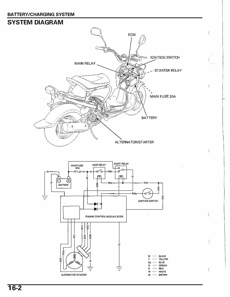
BATTERY/CHARGING SYSTEM
SYSTEM DIAGRAM
G
1 6-2
ECM 0
MAIN RELAY
BATTERY
ALTERNATOR/STARTER
MAIN FUSE MAIN RELAY 2DA
Ar�Rml
� RIG ---J>4--4-- RIG�
:J_____Jt��A/B"_Qj I
ENGINE CONTROL MODUlE (ECM)
ALTERNATOR/STARTER
-� � IGNITION SWITCH
81 BLACK Y •·•·•·• YELLOW Bu •·•·•·• BLUE G •••·•·• GREEN A RED W ....... WHITE Br ·••··•· BROWN

SERVICE INFORMATION
GENERAL
A WARNING
BATTERY/CHARGING SYSTEM
• The battery gives off explosive gases; keep sparks, flames and cigarettes away. Provide adequate ventilation when charging.
• The battery contains sulfuric acid (electrolyte). Contact with skin or eyes may cause severe burns. Wear protective clothing and a face shield. - If electrolyte gets on your skin, flush with water. - If electrolyte gets in your eyes, flush with water for at least 1 5 minutes and call a physician immediately.
• Electrolyte is poisonous. - If swallowed, drink large quantities of water or milk and call your local Poison Control Center or a call a physician
immediately.
NOTICE I • Always turn off the ignition switch before disconnecting any electrical component. • Some electrical components may be damaged if terminals or connectors are connected or disconnected while the igni-
tion switch is in the ON position and current is present.
• For extended storage, remove the battery, give it a full charge, and store it in a cool, dry space. • For a battery remaining in a stored scooter, disconnect the negative battery cable from the battery. • The battery sealing caps should not be removed. Attempting to remove the sealing caps from the cells may damage the
battery. • The maintenance free (MF) battery must be replaced when it reaches the end of its service life. • The battery can be damaged if overcharged or undercharged, or if left to discharge for long period. These same condi
tions contribute to shortening the "life span" of the battery. Even under normal use, the performance of the battery deteriorates after 2-3 years.
• Battery voltage may recover after battery charging, but under heavy load, battery voltage will drop quickly and eventually die out. For this reason, the charging system is often suspected as the problem. Battery overcharging often results from problems in the battery itself, which may appear to be an overcharging symptom. If one of the battery cells is shorted and battery voltage does not increase, the regulator/rectifier in the ECM supplies excess voltage to the battery. Under these conditions, the electrolyte level goes down quickly.
• Before troubleshooting the charging system, check for proper use and maintenance of the battery. Check if the battery is frequently under heavy load, such as having the turn signal light and taillight on for long periods of time without riding the scooter.
• The battery will self-discharge when the scooter is not in use. For this reason, charge the battery every 2 weeks to prevent sulfation from occurring.
• Filling a new battery with electrolyte will produce some voltage, but in order to achieve its maximum performance, always charge the battery. Also, the battery life is lengthened when it is initially charged.
• When checking the charging system, always follow the steps in the troubleshooting flow chart (page 1 6-5). • This scooter has alternator/starter. The alternator/starter has alternator and starter motor functions. • The regulator/rectifier is located in the ECM. • The alternator/starter service may be done with the engine in the frame. For alternator/starter removal/installation, See
page 1 2-4.
BATTERY CHARGING
• This model comes with a maintenance free (MF) battery. Remember the following about M F batteries - Use only the electrolyte that comes with the battery. - Use all of the electrolyte. - Seal the battery properly. - Never open the seals after installation.
• For battery charging, do not exceed the charging current and time specified on the battery. Using excessive cu rrent or extending the charging time may damage the battery.
BATTERY TESTING
Refer to the battery tester's Operation Manual for the recommended battery testing procedure. The recommended battery tester puts a "load" on the battery so the actual battery condition of the load can be measured.
Recommended battery tester: BM-210-AH (U.S.A. only), BM-210 or BATTERY MATE (MTPOB-0192, U.S.A. only) or equivalent
1 6-3
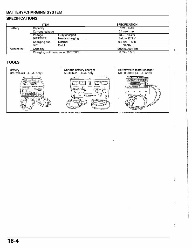
BATTERY /CHARGING SYSTEM
SPECIFICATIONS
ITEM Battery I Capacity
Cu rrent leakage Voltage Fully charged I20'C/6B'FI Needs charging Charging cur- Normal rent Quick
Alternator Capacity Charging coil resistance I20'C/68'F)
TOOLS
Battery BM-210-AH I U.S.A. only)
1 6-4
Christie battery charger MC1012/2 (U.S.A. only)
SPECIFICATION 12V 6 Ah
0.1 rnA max. 13.0 13.2 v Below 1 2.3 V 0.6 A/5 10 h
3A/1 h 190W/5,000 rpm
0.05 0.5 Q
BatteryMate tester/charger MTPOB-0192 (U.S.A. only)
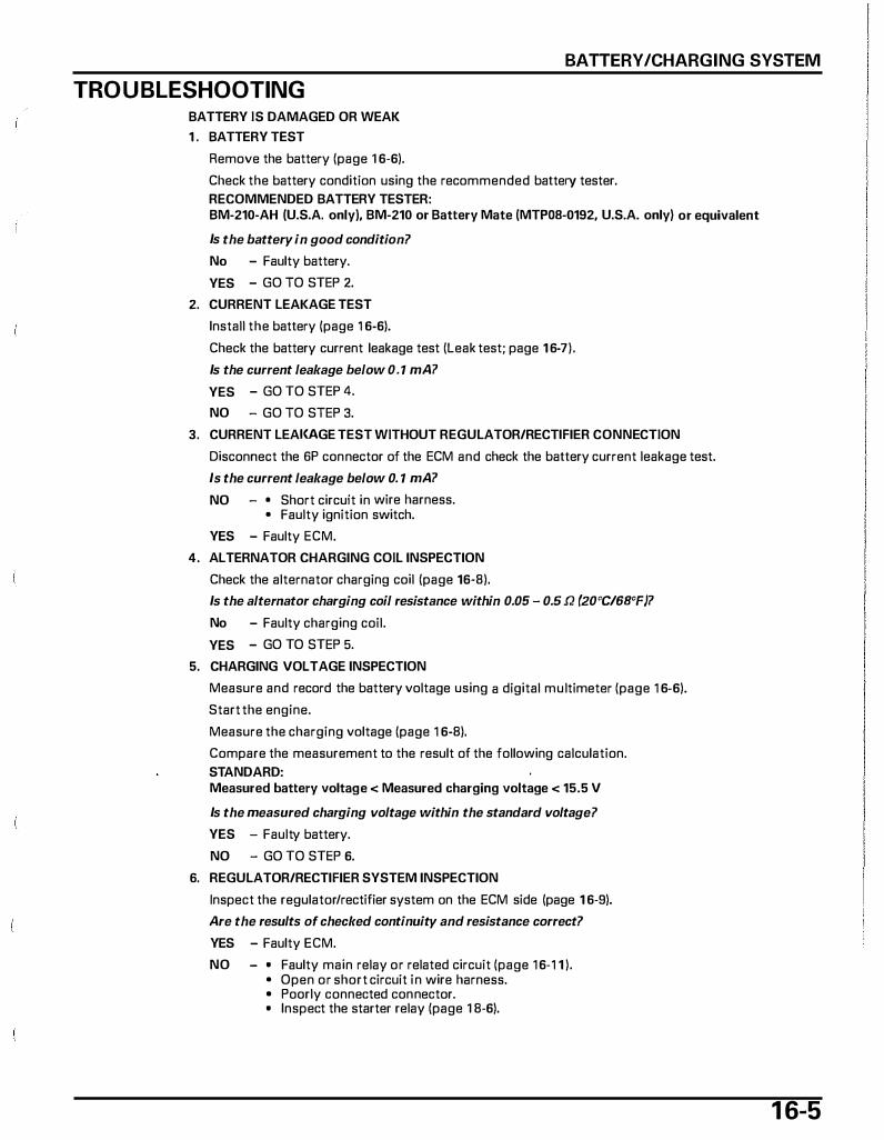
BATTERY/CHARGING SYSTEM
TROUBLESHOOTING BATTERY IS DAMAGED OR WEAK
1 . BATTERY TEST
Remove the battery (page 1 6-6).
Check the battery condition using the recommended battery tester. RECOMMENDED BATTERY TESTER: BM-210-AH (U.S.A. only), BM-210 or Battery Mate (MTPOB-0192, U.S.A. only) or equivalent
Is the battery in good condition?
No - Faulty battery.
YES - GO TO STEP 2.
2. CURRENT LEAKAGE TEST
Install the battery (page 1 6-6).
Check the battery current leakage test (Leak test; page 1 6-7).
Is the current leakage below 0.1 mA7
YES - GO TO STEP 4.
NO - GO TO STEP 3.
3. CURRENT LEAKAGE TEST WITHOUT REGULATOR/RECTIFIER CONNECTION
Disconnect the 6P connector of the ECM and check the battery current leakage test.
Is the current leakage below 0. 1 mA7
NO - • Short circuit in wire harness. • Faulty ignition switch.
YES - Faulty ECM.
4. ALTERNATOR CHARGING COIL INSPECTION
Check the alternator charging coil (page 16-8).
Is the alternator charging coil resistance within 0.05 - 0.5 Q (20'C/68'F)7
No - Faulty charging coil.
YES - GO TO STEP 5.
5. CHARGING VOLTAGE INSPECTION
Measure and record the battery voltage using a digital multimeter (page 1 6-6).
Start the engine.
Measure the charging voltage (page 1 6-8).
Compare the measurement to the result of the following calculation. STANDARD: Measured battery voltage < Measured charging voltage < 15.5 V
Is the measured charging voltage within the standard voltage?
YES - Faulty battery.
NO - GO TO STEP 6.
6. REGULATOR/RECTIFIER SYSTEM INSPECTION
Inspect the regulator/rectifier system on the ECM side (page 1 6-9).
Are the results of checked continuity and resistance correct?
YES - Faulty ECM.
NO - o Faulty main relay or related circuit (page 1 6-1 1 ). • Open or short circuit in wire harness. • Poorly connected connector. o Inspect the starter relay (page 1 8-6).
1 6-5
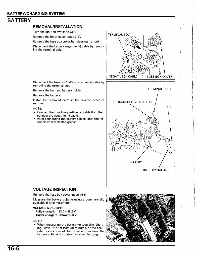
BATTERY/CHARGING SYSTEM
BATTERY
REMOVAL/INSTALLATION
Turn the ignition switch to OFF.
Remove the inner cover (page 3-5).
Remove the fuse box cover by releasing its hook.
Disconnect the battery negative (-) cable by removing the terminal bolt.
Disconnect the fuse box/battery positive (+) cable by �================�
1 6-6
removing the terminal bolt.
Remove the bolt and battery holder.
Remove the battery.
Install the removed parts in the reverse order of removal.
NOTE: • Connect the fuse box/positive (+) cable first, then
connect the negative (-) cable. • After connecting the battery cables, coat the ter
minals with dielectric grease.
VOLTAGE INSPECTION
Remove the fuse box cover (page 1 6-6).
Measure the battery voltage using a commercially available digital multimeter.
VOLTAGE (20"C/68"F): Fully charged: 13.0 - 13.2 V Under charged: Below 12.3 V
NOTE: • When measuring the battery voltage after charg
ing, leave it for at least 30 minutes, o r the accurate results cannot be obtained because the battery voltage fluctuates just after charging.
TERMINAL BOLT
FUSE BOX/POSITIVE (+) CABLE
BOLT
BATIERY
BATIERY HOLDER

BATTERY TESTING
Refer to the instructions that are appropriate to the battery testing equipment available to you.
TOOL: Battery tester BM-210-AH, BM-210 or BATTERY
MATE (MTPOB-0192, U.S.A. only) or equivalent
BATTERY CHARGING (U.S.A. only)
Refer to the instructions that are appropriate to the battery charging equipment available to you.
TOOL: Battery charger Christie battery charger (MC1012/2,
U.S.A. only) or BATTERY MATE (MTPOS-0192, U.S.A. only) or equivalent
CHARGING SYSTEM INSPECTION
CURRENT LEAKAGE TEST
Turn the ignition switch to OFF and disconnect the negative (-) cable from the battery. Connect the ammeter (+) probe to the negative (-) cable and the ammeter (-) probe to the battery negative (-) terminal. With the ignition switch turned to OFF, measure the current leakage.
NOTE: • When measuring curT-ent using a tester, set it to a
high range, and then bring the range down to an appropriate level. Current flow higher than the range selected may blow aut the fuse in the tester.
• While measuring current, do not turn the ignition switch to ON. A sudden surge of current switch may blow out the fuse in the tester.
SPECIFIED CURRENT LEAKAGE: 0.1 rnA max.
If current leakage exceeds the specified value, a shorted circuit is the probable cause. Locate the short by disconnecting connections one by one and measuring the current.
BATTERY/CHARGING SYSTEM
1 6-7
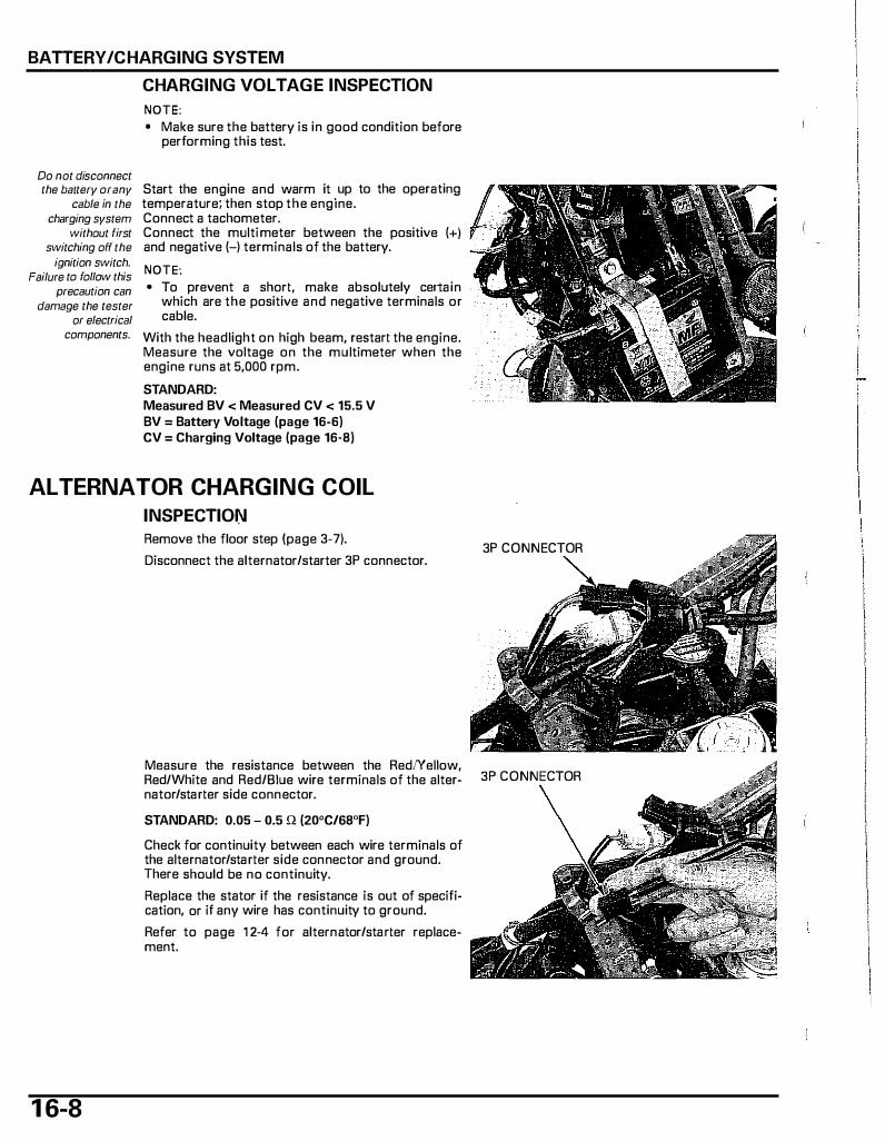
BATTERY /CHARGING SYSTEM
Do not disconnect
CHARGING VOLTAGE INSPECTION
NOTE: • Make sure the battery is in good condition before
performing this test.
the battery orany Start the engine and warm it up to the operating cable in the temperature; then stop the engine.
charging system Connect a tachometer. without first Connect the multi meter between the positive (+)
switching off the and negative (-) terminals of the battery. ignition switch.
Failure to follow this NOTE: precaution can
damage the tester or electrical
components.
• To prevent a short, make absolutely certain which are the positive and negative terminals or cable.
With the headlight on high beam, restart the engine. Measure the voltage on the multimeter when the engine runs at 5,000 rpm.
STANDARD: Measured BV < Measured CV < 15.5 V BV = Battery Voltage (page 16-6) CV = Charging Voltage (page 16·8)
ALTERNATOR CHARGING COIL
INSPECTIOI:\I
Remove the floor step (page 3-7).
Disconnect the alternator/starter 3P connector. 3P CONNECTOR
Measure the resistance between the RedNellow, Red/White and Red/Blue wire terminals of the alter- 3P CONNECTOR
1 6-8
nator/starter side connector.
STANDARD: 0.05 - 0.5 n (20°C/68°F)
Check for continuity between each wire terminals of the alternator/starter side connector and ground. There should be no continuity.
Replace the stator if the resistance is out of specification, or if any wire has continuity to ground.
Refer to page 1 2-4 for alternator/starter replacement.
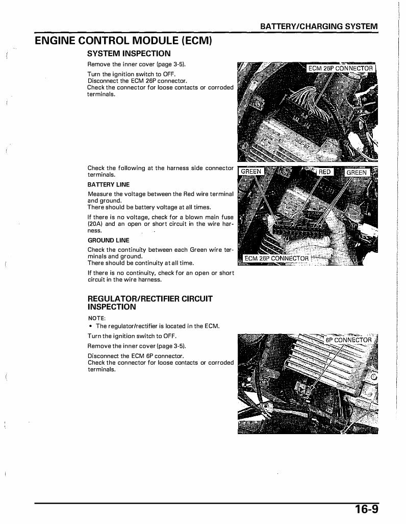
ENGINE CONTROL MODULE (ECM)
SYSTEM INSPECTION
Remove the inner cover {page 3-5).
Turn the ignition switch to OFF. Disconnect the ECM 26P connector. Check the connector for loose contacts or corroded terminals.
Check the following at the harness side connector terminals.
BATTERY LINE
Measure the voltage between the Red wire terminal and ground. There should be battery voltage at all times.
If there is no voltage, check for a blown main fuse (20A) and an open or short circuit in the wire harness.
GROUND LINE
Check the continuity between each Green wire terminals and ground. There should be continuity at all time.
If there is no continuity, check for an open or short circuit in the wire harness.
REGULATOR/RECTIFIER CIRCUIT INSPECTION
NOTE: • The regulator/rectifier is located in the ECM.
Turn the ignition switch to OFF.
Remove the inner cover {page 3-5).
Disconnect the ECM 6P connector. Check the connector for loose contacts or corroded terminals.
BATTERY/CHARGING SYSTEM
1 6-9
BATTERY/CHARGING SYSTEM
1 6- 1 0
Check the following at the harness side connector terminals.
BATTERY LINE
Measure the voltage between the Red wire terminal and ground. When the ignition switch is turned to OFF, there is no voltage and when the ignition switch is turned to ON, there should be voltage. If the measurements are abnormal, inspect the main relay (page 1 6-1 1 ).
GROUND LINE
Check the continuity between the Green wire termi-nal and ground. l,::.i�:;:� There should be continuity at all time.
If there is no continuity, check for an open or short circuit in the wire harness.
CHARGING COIL LINE
Measure the resistance between the Red/yellow, Red/white and Red/blue wire terminals.
STANDARD: 0.05 - 0.5 Q (20 "C/68 "F)
IGNITION SWITCH CIRCUIT INSPECTION
Remove the front cover (page 3-6).
Turn the ignition switch to OFF.
Disconnect the ignition switch 3P connector. Measure the voltage between the Red/b'lue wire terminal and ground. There should be battery voltage at all time.
If there is no voltage, check the following: - Open or short circuit in wire harness. - ECM battery line (page 1 6-1 0).
Disconnect the ECM 26P connector.
Check the continuity of the Red/green wire terminals between the ignition switch 3P connector and ECM 26P connector. There should be continuity.
REMOVAL/INSTALLATION
Remove the inner cover (page 3-5).
Turn the ignition switch to OFF. Disconnect the ECM 6P and 26P connectors. Remove the bolts and ECM.
Installation is in the reverse order of removal.
MAIN RELAY
SYSTEM INSPECTION
NOTE: • Make sure the battery line and ignition switch cir
cuit of the ECM is normal, before performing this inspection.
Remove the inner cover (page 3-5).
Remove the main relay.
1 . Main Relay Power Voltage Inspection
Turn the ignition switch to OFF. Measure the voltage between the Red wire terminal and ground.
Is there battery voltage?
BATTERY/CHARGING SYSTEM
NO - • Check for an open or short circuit in '----.,.,.. the wire harness.
• Check for a blown main fuse (20A).
YES - GO TO STEP 2.
1 6- 1 1
BATTERY/CHARGING SYSTEM
2. Main Relay Operation Voltage Inspection
Turn the ignition switch to ON. Measure the voltage between the Red/green wire terminal and ground.
Is there battery voltage?
NO - • Check for an open or short circuit in the wire harness.
• Check the ignition switch (page 1 9-20)
• Check for loose or poor contact of related terminals.
YES - GO TO STEP 3.
3. Main Relay Circuit Voltage Inspection
Turn the ignition switch to ON. Measure the voltage between the Red/green (+) and Green/white (-) wire terminals.
Is there battery voltage?
NO - • Check for an open or short circuit in '----=
1 6- 1 2
the wire harness. If it is normal, check the ECM ground line.
YES - GO TO STEP 4.
4. Starter Relay Circuit Inspection
Turn the ignition switch to OFF. Disconnect the ECM 6P connector. Check the continuity between the Red/black wire terminal at the main relay connector and the Red wire terminal at the ECM 6P connector.
Does continuity exist?
NO - • Check for an open or short circuit in the wire harness.
• Check the starter relay (page 18-6).
YES - Correct.
OPERATING INSPECTION
Check for continuity between the A and B terminals.
There is usually no continuity; there should be continuity when the battery is connected to C (+) and D (-) terminals.
INSTALLATION
Installation is i n the reverse order of removal.
D
c
A
B

SYSTEM DIAGRAM····· ................................ 17-2
SERVICE INFORMATION ···························· 17-3
TROUBLESHOOTING·································· 17-4
IGNITION SYSTEM INSPECTION ··············· 17-5
1 7. IG N ITION SYSTEM
IGNITION COIL ·············································17-7
IGNITION TIMING ········································17-7
THROTTLE POSITION SENSOR ··················17-8
1 7-1

IGNITION SYSTEM
SYSTEM DIAGRAM
"' j_
1 7-2
THROTILE POSITION SENSOR IGNITION SWITCH
' · MAIN FUSE 20A
BATIERY
IGNITION COIL
SPARK PLUG
IGNITION PULSE GENERATOR
MAIN FUSE 20A
ENGINE CONTROL MODULE (ECM)
IGNITION SWITCH
ENGINE STOP SWITCH
BVA � e--- BIIW----�
IGNITION PULSE GENERATOR
SERVICE CHECK CONNECTOR
THROlTLE SENSOR 81 •·•·•·• BLACI( Y ····•·• YELLOW
.t SPARK PLUG
"" ....... BLUE
G GREEN R ....... RED
w ....... WHITE
IGNITION SYSTEM
SERVICE INFORMATION
GENERAL
• Some electrical components may be damaged if terminals or connectors are connected or disconnected while the igni� tion switch is turned to ON and current is present.
• When servicing the ignition system, always follow the steps in the troubleshooting sequence on (page 17-4). • The ignition timing cannot be adjusted since the Engine Control Module (ECM) is factory preset. • The ECM may be damaged if dropped. Also, if the connector is disconnected when current is flowing, the excessive
voltage may damage the ECM. Always turn the ignition switch to OFF before servicing. • A faulty ignition system is often related to poorly connected or corroded connectors. Check those connections before
proceeding. • Although the engine control module is controlling ignition timing according to engine speed, ignition timing is assisted
also with the signal from the throttle position sensor and ECT sensor. • Use a spark plug of the correct heat range. Using a spark plug with an incorrect heat range can damage the engine. • For ignition switch and ECT sensor inspection, refer to page 1 9-20 and page 19-15. • For ignition pulse generator (alternator stator) removal/installation, refer to page 1 2-4.
SPECIFICATION
ITEM Spark plug Standard ('03 - '05 For cold climate (below 5 'C/41 'F) model) For extended high speed riding Spark plug Standard (After '05 For cold climate (below 5 'C/41 'F) model) For extended high speed riding Spark plug gap Ignition coil peak voltage Ignition pulse generator peak voltage Ignition timing ("F" mark) Throttle position sensor I Resistance (20 'C/68 'F)
I Input voltage
TOOLS
Peak voltage adaptor 07HGJ-0020100
with commercially available digital multimeter ( impedance 10 MQ/DCV minimum)
Ignition Mate peak voltage tester (U.S.A. only)
SPECIFICATIONS CR8EH-9 (NGK), U24FER9 (DENSO) CR7EH-9 (NGK), U22FER9 (DENSO) CR9EH-9 (NGK), U27FER9 (DENSO)
CR8EH-9 (NGK) CR7EH-9 (NGK) CR9EH-9 (NGK)
0.80 - 0.90 m m (0.031 - 0.035 in) 80 V minimum 0.7 V minimum
10'BTDC at 2,000 rpm 4 - 6kQ
4.7 5.3 v
1 7-3
IGNITION SYSTEM
TROUBLESHOOTING • Inspect the following before diagnosing the system.
- Faulty spark plug - Loose spark plug cap or spark plug wire connection - Water got into the spark plug cap (leaking the ignition coil secondary voltage)
• Temporarily exchange the ignition coil with the other good one and perform the spark test. If there is spark, the exchanged ignition coil is faulty.
No spark at plug
Unusual condition Probable cause (check in numerical order) Ignition coil Low peak voltage. 1. Incorrect peak voltage adapter connections. (System is primary normal if measured voltage is over the specifications voltage with reverse connections).
2. The multi meter impedance is too low; below 10 MQ/ DCV.
3. Cranking speed is too low. (Battery is undercharged.) 4. The sampling timing of the tester and measured pulse
were not synchronized (system is normal if measured voltage is over the standard voltage at least once). (Does not apply to Imrie tester).
5. Poorly connected connectors or an open circuit in igni-tion system.
6. Faulty ignition coil. 7. Faulty ECM (in case when above No. 1 - 6 are normal).
No peak voltage. 1. Incorrect peak voltage adapter connections. {System is normal if measured voltage is over the specifications with reverse connections).
2. Battery is under charged. (Voltage drops largely when the engine is started.)
3. Short circuit in engine stop switch wire. 4. Faulty ignition switch or engine stop switch. 5. Loose or poorly connected ECM connectors. 6. Open circuit or poor connection in ground wire of the
ECM. 7. Faulty peale voltage adapter. 8. Faulty ignition pulse generator (Measure peak voltage). 9. Faulty ECM (in case when above No.1 - 8 are normal).
Peak voltage is normal, but no 1. Faulty spark plug or leaking ignition coil secondary cur-spark jumps at the plug. rent.
2. Faulty ignition coil. Ignition pulse Low peak voltage. 1. The multi meter impedance is too low; below 10 MQ/ generator DCV.
2. Cranking speed is too slow. (Battery is undercharged.) 3. The sampling timing of the tester and measured pulse
were not synchronized (system is normal if measured voltage is over the standard voltage at least once).
4. Faulty ignition pulse generator (in case when above No.1 - 3 are normal).
No peak voltage. 1. Faulty peak voltage adapter or Imrie tester. 2. Faulty ignition pulse generator.
1 7-4
IGNITION SYSTEM INSPECTION NOTE: • If there is no spark at the plug, check all connec
tions for loose or poor contact before measuring the peak voltage.
• Use a commercially available digital multimeter (impedance 1 0 MQ/DCV minimum).
• The display value differs depending upon the internal impedance of the multimeter.
IGNITION SYSTEM
Connect the peak voltage adapter to the digital .--------------------, multi meter, or use the peak voltage tester.
TOOLS: lgnitionMate peal< voltage tester (U.S.A. only) or Peak voltage adaptor 07HGJ-0020100
(not available in U.S.A.) with commercially available digital multimeter (impedance 10 MQ/DCV minimum) or lgnitionMate peak voltage tester, MTP-08-0193 (U.S.A. only)
IGNITION COIL PRIMARY PEAK VOLTAGE
NOTE: • Check all system connections before i nspection.
If the system is disconnected, incorrect peak voltage might be measured.
• Check cylinder compression and check that the spark plug is i nstalled correctly.
Remove the floor step (page 3-7).
Disconnect the spark plug cap from the spark plug. Connect a known-good spark plug to the spark plug cap and ground the spark plug to the cylinder as done in a spark test.
With the ignition coil primary wire connected, connect the peale voltage adapter or tester probes to the ignition coil.
TOOLS: lgnitionMate peak voltage tester (U.S.A. only) or Peak voltage adaptor 07HGJ-0020100
(not available in U.S.A.) with commercially available digital multimeter (impedance 10 MQ/DCV minimum) or lgnitionMate peal< voltage tester, MTP-08-0193 (U.S.A. only)
CONNECTION: Black/yellow (+) - Body ground (-)
PEAK VOLTAGE ADAPTOR
Turn the ignition switch to ON and the engine stop ""n"..,"'"'"" switch to " o. ".
1 7-5
�GNITION SYSTEM
Avoid touching the spark plug and
tester probes to prevent electric
shock.
1 7-6
Cranl< the engine with the kiclcstarter and measure the ignition coil primary peak voltage.
PEAK VOLTAGE: 80 V minimum
If the peak voltage is lower than specified value, follow the checks described in the troubleshooting chart (page 1 7-4).
Install the removed parts in the reverse order of removal.
IGNITION PULSE GENERATOR PEAl< VOLTAGE
NOTE: • Check all system connections before inspection.
If the system is disconnected, incorrect peak voltage might be measured.
• Check cylinder compression and make sure the spark plug is installed correctly.
Remove the inner cover (page 3-5).
Turn the ignition switch to OFF. Disconnect the engine control module (ECM) 26P connector.
Connect the peak voltage adapter o r tester probes to the wire harness side connector terminal and body ground.
TOOLS: lgnitionMate peak voltage tester (U.S.A. only) or Peal< voltage adaptor 07HGJ-0020100
(not available in U.S.A.) with commercially available digital multimeter (impedance 10 MQ/DCV minimum) or lgnitionMate peak voltage tester, MTP-08-0193 (U.S.A. only)
CONNECTION: Blue/yellow (+) - Body ground H Crank the engine with the kickstarter and measure the ignition pulse generator peak voltage.
PEAK VOLTAGE: 0.7 V minimum
If the peak voltage measured at the ECM connector is abnormal, measure the peak voltage at the pulse generator connector.
Remove the floor step (page 3-7).
Disconnect the alternator/starter 6P connector and connect the peak voltage tester or adaptor probes to the connector terminals of the pulse generator/ starter side. In the same manner as at the ECM connector, measure the peak voltage and compare it to the voltage measured at the ECM connector.
• If the peak voltage measured at the ECM is abnormal and the one measured at the alternator/starter is normal, the wire harness has an open or short circuit, or loose connection.
• If the peak voltage is lower than standard value, follow the checks described in the troubleshooting chart (page 1 7-4).
Install the removed parts in the reverse order of removal.
IGNITION COIL
REMOVAL/INSTALLATION
Remove the floor step (page 3-7).
Disconnect the spark plug cap from the plug. Disconnect the ignition coil wire connectors. Remove the bolt and ignition coil.
Installation is in the reverse order of removal.
IGNITION TIMING NOTE: • The ignition timing cannot be adjusted since the
ECM is factory preset. • If the ignition timing is incorrect, inspect the
pulse generator and ECM.
IGNITION SYSTEM
6P CONNECTOR
Warm up the engine to normal operating tempera- ,-------------------., ture. Stop the engine and remove the radiator cover (page 7-7) and plug maintenance lid (page 4-6).
1 7-7
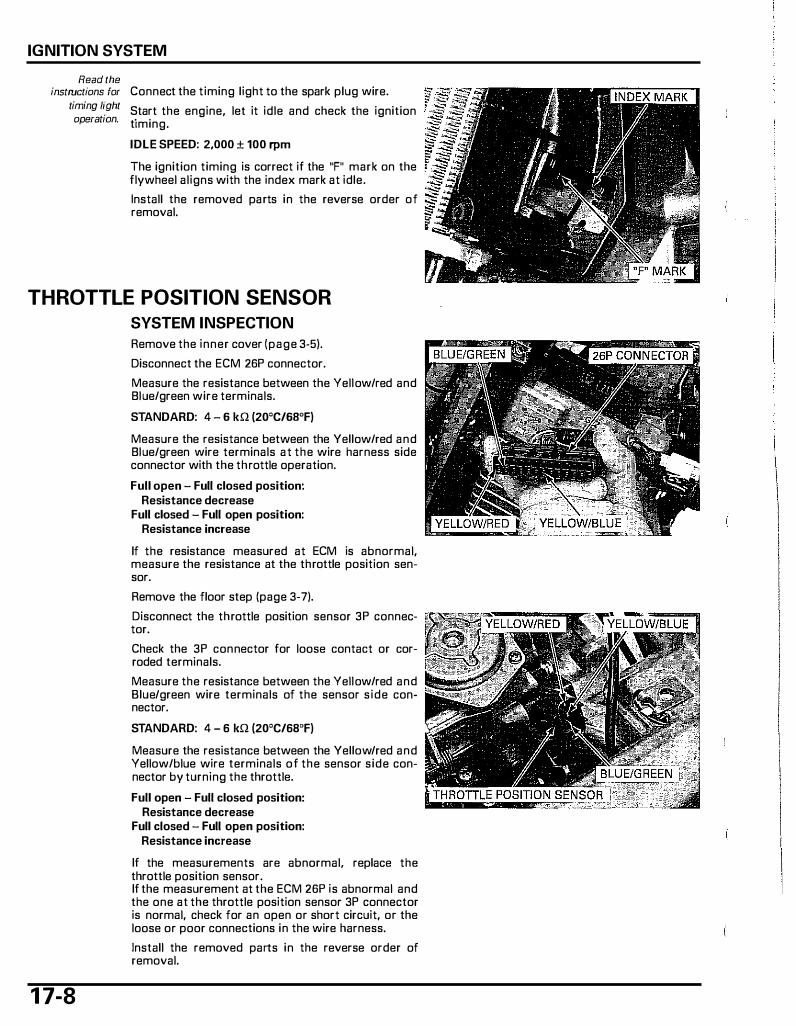
IGNITION SYSTEM
Read the instructions for Connect the timing light to the spark plug wire.
timing fight Start the engine, let it idle and check the ignition operation. timing.
IDLE SPEED: 2,000 ± 100 rpm
The ignition timing is correct if the "F" mark on the flywheel aligns with the index mark at idle.
Install the removed parts in the reverse order of removal.
THROTTLE POSITION SENSOR
SYSTEM INSPECTION
1 7-8
Remove the inner cover {page 3�5).
Disconnect the ECM 26P connector.
Measure the resistance between the Yellow/red and Blue/green wire terminals.
STANDARD: 4 - 6 kQ (20'C/6B'F)
Measure the resistance between the Yellow/red and Blue/green wire terminals at the wire harness side connector with the throttle operation.
Full open - Full closed position: Resistance decrease
Full closed - Full open position: Resistance increase
If the resistance measured at ECM is abnormal, measure the resistance at the throttle position sensor.
Remove the floor step (page 3-7).
Disconnect the throttle position sensor 3P connector.
Check the 3P connector for loose contact or corroded terminals.
Measure the resistance between the Yellow/red and Blue/green wire terminals of the sensor side connector.
STANDARD: 4 - 6 kQ (20'C/68'F)
Measure the resistance between the Yellow/red and Yellow/blue wire terminals of the sensor side connector by turning the throttle.
Full open - Full closed position: Resistance decrease
Full closed - Full open position: Resistance increase
If the measurements are abnormal, replace the throttle position sensor. If the measurement at the ECM 26P is abnormal and the one at the throttle position sensor 3P connector is normal, check for an open or short circuit, or the loose or poor connections in the wire harness.
Install the removed parts in the reverse order of removal.

INPUT VOLTAGE INSPECTION
Remove the floor step (page 3-7).
Disconnect the throttle position sensor 3P connector.
Turn the ignition switch to ON and engine stop switch to " n". Measure the input voltage between the Yellow/red (+) and Blue/green (-) wire terminals of the wire harness side connector.
STANDARD: 4.7 - 5.3 V
If the input voltage is abnormal, o r if there is no input voltage, check for an open o r short circuit i n the wire harness, or loose o r poor ECM connector contact, or battery line and ignition switch circuit of the ECM (page 1 6-9).
If the above check is normal, replace the ECM.
Install the floor step (page 3-7).
REMOVAL/INSTALLATION
Remove the floor step (page 3-7).
Disconnect the throttle position sensor 3P connector. Remove the screw and throttle position sensor from the carburetor.
Install the throttle position sensor by aligning the g roove of the throttle position sensor with the flat of the throttle shaft.
I NOTICE I The throttle position sensor may be damaged if you do nat install it correctly.
Install and tighten the screw securely. Connect the throttle position sensor 3P connector.
Install the floor step (page 3-7).
IGNITION SYSTEM
1 7-9
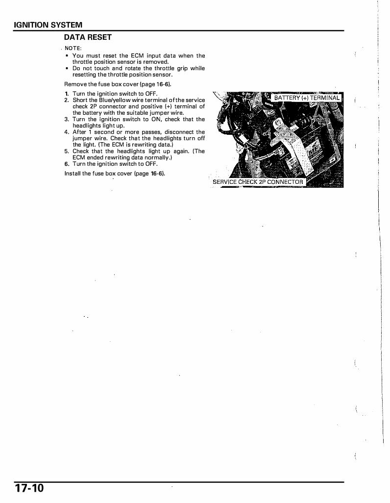
IGNITION SYSTEM
1 7- 1 0
DATA RESET
NOTE: • You must reset the ECM input data when the
throttle position sensor is removed. • Do not touch and rotate the throttle grip while
resetting the throttle position sensor.
Remove the fuse box cover (page 1 6-6).
1. Turn the ignition switch to OFF. 2. Short the Blue/yellow wire terminal ofthe service
check 2P connector and positive (+) terminal of the battery with the suitable jumper wire.
3. Turn the ignition switch to ON, check that the headlights light up.
4. After 1 second or more passes, disconnect the jumper wire. Check that the headlights turn off the light. (The ECM is rewriting data.)
5. Check that the headlights light up again. (The ECM ended rewriting data normally.)
6. Turn the ignition switch to OFF.
Install the fuse box cover (page 16-6).
SYSTEM DIAGRAM ..................................... 18-2
SERVICE INFORMATION ···························· 18-3
TROUBLESHOOTING·································· 18-4
1 8. ELECTRIC STARTER
STARTER RELAY ··································· ·······18-6
ENGINE CONTROL MODULE (ECM}···········18-8
1 8-1
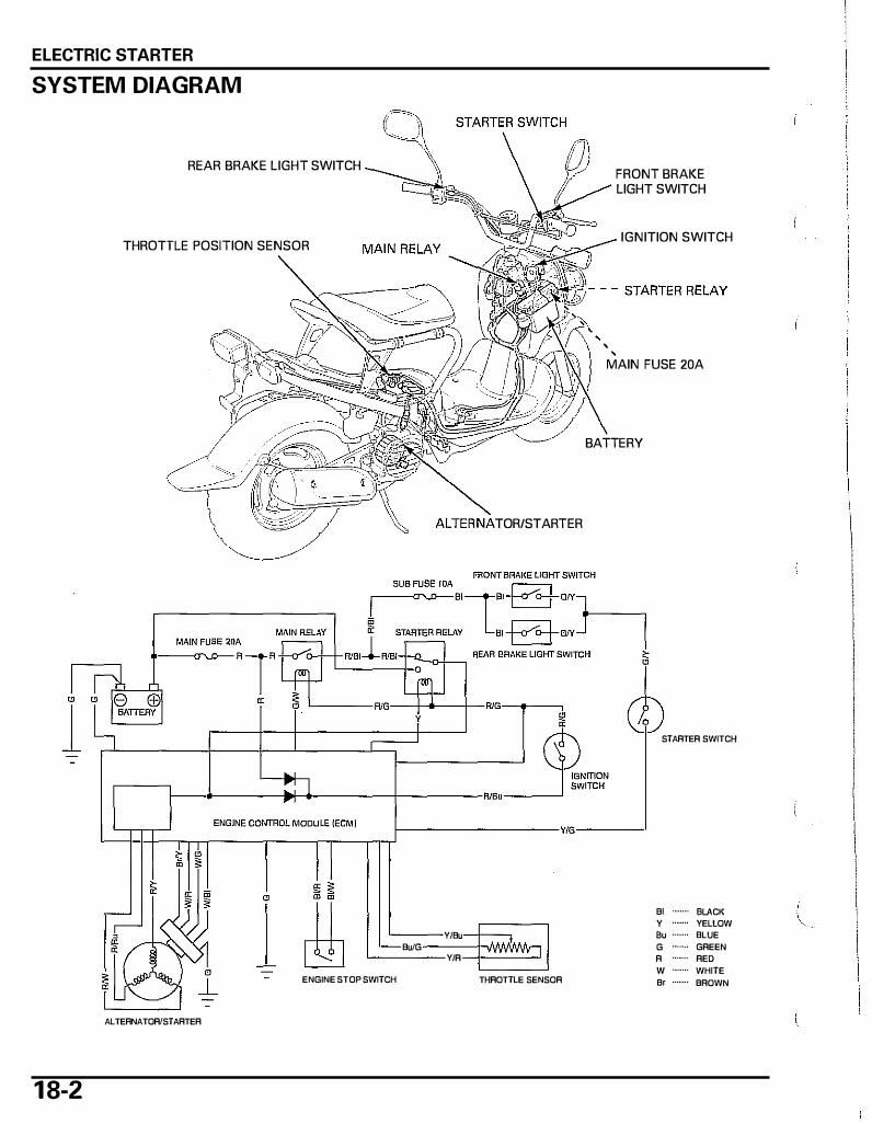
ELECTRIC STARTER
SYSTEM DIAGRAM
REAR BRAKE LIGHT SWITCH
THROTTLE POSITION SENSOR
TOR/STARTER
L ---- RJG--+_._-+-RIG-.---,
' '
FRONT BRAKE LIGHT SWITCH
IGNITION SWITCH
MAIN FUSE 20A
BATTERY
;=t:������:���:LI----��--�:e��----���-��:�-�yt-���������-
-1 � =' I RIB"=-_]1�
STARTER SWITCH
ENGINE CONTROL MODU LE (ECM) L=f=J=f=�rrTT_=-::_::::_::::.,:_.:=_:::_::::;_=;:::::_::,,.,J----------vto-----"
Bl ....... BLACK y YELLOW
Y/Bu "" ....... BLUE
Bu/G G ....... GREEN Y/R R ....... RED
w ....... WHITE ENGINE STOP SWITCH THROTTLE SENSOR Be ....... BROWN
ALTERNATOR!STARTER
1 8-2
\.
ELECTRIC STARTER
SERVICE INFORMATION
GENERAL
• Some electrical components may be damaged if terminals or connectors are connected or disconnected while the igni-tion switch is turned to ON and current is present.
• When servicing the electric starter, always follow the steps in the troubleshooting sequence on (page 1 8:4). • This scooter has adopted an alternator/starter that functions like bath an alternator and starter motor. • A weal< battery may be unable to turn the starter quickly enough, or supply adequate ignition current. • For the a lternator/starter removal/installation, See page 1 2-4. • Refer to page 1 8-6 and page 16-1 1 to check the stator and main relay. • Refer to page 1 9-20, page 1 9-22 and page 1 9-22 to check the ignition switch, starter switch and brake light switch.
1 8-3

E LECTRIC STARTER
TROUBLESHOOTING
1 8-4
Alternator/Starter does not turn (Flywheel does not turn)
1. Fuse Inspection
Check for a blown main fuse (20A) and sub fuses ( 1 0A).
Is either fuse blown?
YES - Replace the fuse.
NO - GO TO STEP 2.
2. Battery Inspection
Check if the battery is fully charged and is in good condition. Also check that there is no loose terminals or connections.
Is the battery in good condition?
YES - GO TO STEP 3.
NO - Fully charge or replace the battery.
3. Starter Relay Operation Check
With the ignition switch turned to ON, squeeze the brake lever, push the starter switch and checldor a "Click" sound from the starter relay.
Is a "Click" heard?
YES - GO TO STEP 4.
NO - GO TO STEP 9.
4. Battery Ground Circuit Inspection
Check the battery ground circuit at the ECM (page 16-9). Check for continuity between the Green wire terminals of the wire harness and body ground.
Does continuity exist?
YES - GO TO STEP 5.
NO - Open circuit in the Green wire between the ECM 6P and 26P connector and battery.
5. Stator Coil Inspection
Check the stator coil resistance at the ECM side (page 1 6-B).
Is the resistance held within the standard?
YES - GO TO STEP 6.
NO - • Open circuit in the Red/yellow, Red/blue and Red/white wires between the ECM BP con-nector and alternator 3P connector.
• Faulty stator coil. • Loose or poorly connected stator related connector.
6. Starter Relay Circuit Inspection
Inspect the starter relay circuit at the ECM (page 18-6).
Is the starter relay circuit in good condition?
YES - GO TO STEP 7.
NO - • Open circuit in the Red wire between the ECM 6P connector and starter relay.
7. Starter Relay Inspection
Check the operation of the starter relay (page 1 8-6).
Is the starter relay in good condition?
YES - • GO TO STEP 8. (if from step 6) • GO TO STEP 10. (if from step 9)
NO - Faulty starter relay.

ELECTRIC STARTER
8. Angle Sensor Circuit Inspection
I nspect the angle sensor circuit at the pulse generator/starter 6P connector side (page 18-8).
Does continuity exist?; Is the voltage normal?
NO - • Open circuit in the Green wire between the pulse generator/starter 6P connector and ground.
• Open circuit in the Brown/yellow, White/red, White/green and White/black wires between the pulse generator/starter 6P connector and ECM 26P connector.
• Faulty ECM.
YES - Faulty angle sensor ( replacement of stator assembly required).
9. Starter Switch Circuit Inspection
Inspect the starter switch circuit at the ECM side (page 1 8-8).
Is the starter switch circuit normal?
YES - GO TO STEP 7.
NO - • Open circuit in the Green/yellow wire between the brake light switch and starter switch. • Faulty starter switch. • Open circuit in Yellow/green wire between the starter switch and ECM. • Loose or poorly connected connector of starter switch circuit.
10. Starter Relay Battery Voltage Line Inspection
Inspect the starter relay battery voltage line {page 18-6).
Is the battery voltage tine normal?
YES - GO TO STEP 1 1 .
N O - • Open circuit i n the Red/green wire between the starter relay and ignition switch. • Loose or poorly connected connector.
1 1 . Starter Relay Ground Line
Inspect the starter relay coil ground line (page 1 8-7).
Is the starter relay ground circuit in good condition?
YES - Replace the ECM and inspect again.
NO - Open circuit in the Yellow wire between the starter relay and ECM.
1 8-5
ELECTRIC STARTER
STARTER RELAY
REMOVAL/INSTALLATION
1 8-6
Remove the inner cover (page 3-5).
Disconnect the battery negative (-) cable and remove the fuse box cover (page 1 6-6).
Remove the terminal bolt and disconnect the fuse box/battery positive (+) cable. Remove the starter relay from the fuse box.
Install the removed parts in the reverse order of removal.
OPERATION INSPECTION
Remove the starter relay. Check for continuity between the A and D terminals. There should be continuity at the terminals. There should be no continuity when the battery is connected to E (+) and C (-) terminals of the starter relay.
Check for continuity between the A and B terminals. There should be no continuity at the terminals. There should be continuity when the battery is connected to E (+) and C (-) terminals of the starter relay.
RELAY CIRCUIT INSPECTION
NOTE: • Make sure the main relay and relative circuit is
normal before performing this inspection.
Remove the starter relay. Connect the fuse box/battery positive (+) cable and negative (-) cable.
BATTERY VOLTAGE LINE
Measure the voltage between the Red/green wire terminal of the starter relay connector and ground.
If battery voltage is present only when the ignition switch is turned to ON, the circuit is normal.
A
c
D E B
FUSE BOX
�D c:J 1n o
� m RED/GREEN YELLOW
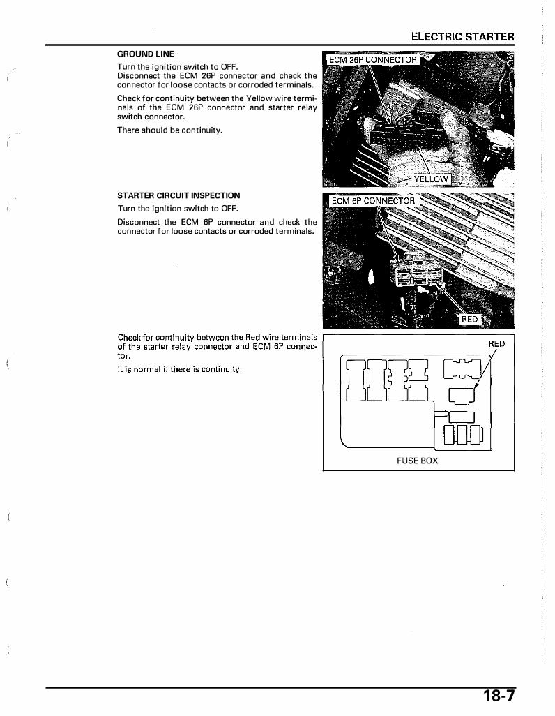
GROUND LINE
Turn the ignition switch to OFF. Disconnect the ECM 26P connector and check the connector for loose contacts or corraded terminals.
Check for continuity between the Yellow wire terminals of the ECM 26P connector and starter relay switch connector.
There should be continuity.
STARTER CIRCUIT INSPECTION
Turn the ignition switch to OFF.
Disconnect the ECM 6P connector and check the connector for loose contacts or corroded terminals.
[][]) FUSE BOX
1 8-7

ELECTRIC STARTER
ENGINE CONTROL MODULE (ECM)
STARTER SWITCH CIRCUIT INSPECTION
1 8-8
NOTE: • Make sure the brake light circuit is normal before
performing this i nspection (page 19-22).
Remove the front cover (page 3-6).
Disconnect the ECM 26P connector and brake light switch connectors.
Check for continuity between the Yellow/green wire terminal of the ECM 26P connector and the G reen/ yellow wire terminal of the brake light switch connectors.
There is usually no continuity, there should be continuity when pushing the starter switch.
ANGLE SENSOR CIRCUIT INSPECTION
Remove the floor step (page 3-7).
Disconnect the pulse alternator/starter 6P connector and check the connector for loose contacts of corroded terminals.
Check for continuity between the Green wire terminal of the harness side and ground. There should be continuity.
Turn the ignition switch to ON. Measure the voltage between the following terminals of harness side:
STNDARD: Brown/yellow(+) and Green(-) terminals:about 10 V White/red(+) and Green(-) terminals: about 8.5 V White/green(+) and Green(-) terminals: about 8.5 V White/black(+) and Green(-) terminals: about 8.5 V
6P CONNECTOR

1 9. LIGHTS/METERS/SWITCH ES
SYSTEM LOCATION· . . . . . . . . . . . . . . . . . . . . . . . . . . . . . . . . . . . 19-2 FUEL RESERVE INDICATOR/ FUEL RESERVE SENSOR · · · · · · · · · · · · · · · · · · · · · · · · · · ·19-12
SERVICE INFORMATION · · · · · · · · · · · · · · · · · · · · · · · · ·· · · 19-3 COOLANT TEMPERATURE INDICATOR/
HEADLIGHTS . . . . . . . . . . . . . . . . . . . . . . . . . . . . . . . . . . . . . . . . . . . . . . . 1 9-4 ECT SENSOR · · · · · · · · · · · · · · · · · · · · · · · · · · · · · · · · · · · · · · · · · · · · · · 19-15
TURN SIGNAL LIGHT · · · · · · · · · · · · · · · · · · · · · · · · · · · · · · · · · · 19-6 FUEL PUMP · · · · · · · · · · · · · · · · · · · · · · · · · · · · · · · · · · · · · · · · · · · · · · · ·19-18
BRAKE/TAIL LIGHT . . . . . . . . . . . . . . . . . . . . . . . . . . . . . . . . . . . . . 19-8 IGNITION SWITCH · · · · · · · · · · · · · · · · · · · · · · · · · · · · · · · · · · · · · 19-20
TURN SIGNAL INDICATOR· · · · · · · · · · · · · · · · · · · · · · · 19-10 HANDLEBAR SWITCHES · · · · · · · · · · · · · · · · · · · · · · · · · · · 19-21
HIGH BEAM INDICATOR · · · · · · · · · · · · · · · · · · · · · · · · · · · 19-10 BRAKE LIGHT SWITCH · · · · · · · · · · · · · · · · · · · · · · · ·· · · · · · 19-22
SPEEDOMETER · · · · · · · · · · · · · · · · · · · · · · · · · · · · · · · · · · · · · · · · · 19-1 1 HORN · · · · · · · · · · · · · · · · · · · · · · · · · · · · · · · · · · · · · · · · · · · · · · · · · · · · · · · · · · 19-23
LOAD CUT RELAY · · · · · · · · · · · · · · · · · · · · · · · · · · · · · · · · · · · · · ·19-23
El I
1 9-1
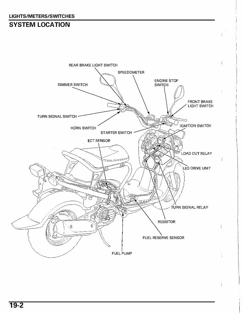
LIGHTS/METERS/SWITCHES
SYSTEM LOCATION
REAR BRAKE LIGHT SWITCH
SPEEDOMETER
ENGINE STOP
TURN SIGNAL SWITCH
HORN SWITCH STARTER SWITCH
FUEL RESERVE SENSOR
FUEL PUMP
1 9-2
FRONT BRAKE LIGHT SWITCH
DRIVE UNIT
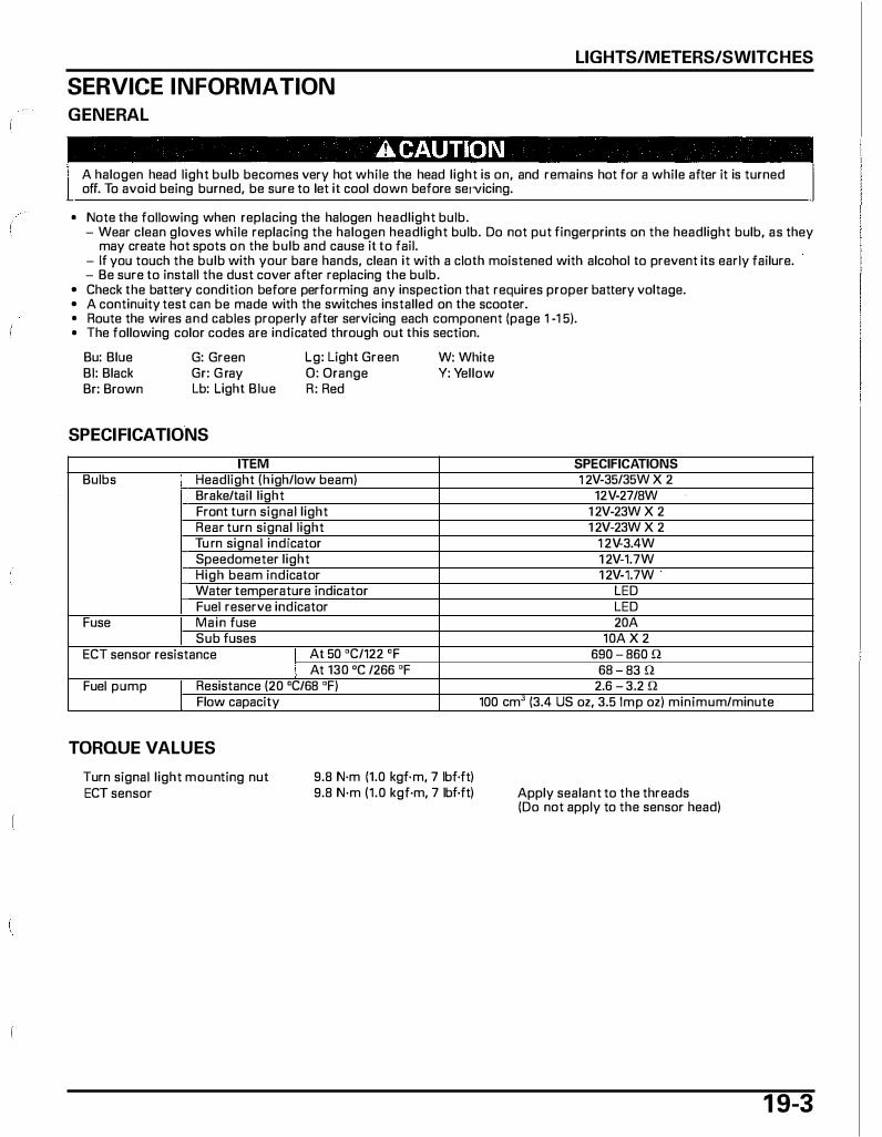
LIGHTS/METERS/SWITCHES
SERVICE INFORMATION
GENERAL
A halogen head light bulb becomes very hot while the head light is on, and remains hot for a while after it is turned off. To avoid being burned, be sure to let it cool down before seJVicing.
• Note the following when replacing the halogen headlight bulb. - Wear clean gloves while replacing the halogen headlight bulb. Do not put fingerprints on the headlight bulb, as they
may create hot spots on the bulb and cause it to fail. - If you touch the bulb with your bare hands, clean it with a cloth moistened with alcohol to prevent its early failure. - Be sure to install the dust cover after replacing the bulb.
• Check the battery condition before performing any inspection that requires proper battery voltage. • A continuity test can be made with the switches installed on the scooter. • Route the wires and cables properly after servicing each component (page 1 -1 5). • The following color codes are indicated through out this section.
Bu: Blue Bl: Black Br: Brown
G: Green Gr: G ray Lb: Light Blue
Lg: Light Green 0: Orange R: Red
SPECIFICATIONS
ITEM Bulbs Headlight (high/low beam)
Brake/tail light Front turn signal light Rear turn signal light Tu rn signal indicator Speedometer light High beam indicator Water temperature indicator Fuel reserve indicator
Fuse Main fuse Sub fuses
ECT sensor resistance I At 50 °C/122 °F
Fuel pump I At 130 oc /266 OF
Resistance (20 °C/68 °F)
W: White Y: Yellow
SPECIFICATIONS 1 2V-35/35W X 2
12V-27/8W 1 2V-23W X 2 1 2V-23W X 2
1 2V-3.4W 1 2V-1.7W 1 2V-1.7W .
LED LED 20A
10A X 2 690 - 860 n
68 83 n 2.6 - 3.2 n
I Flow capacity 100 em' (3.4 US oz, 3.5 Imp oz) minimum/minute
TORQUE VALUES
Turn signal light mounting nut ECT sensor
9.8 N·m (1.0 kgf·m, 7 lbf·ft) 9.8 N·m (1.0 kgf·m, 7 lbf·ft) Apply sealant to the threads
(Do not apply to the sensor head)
1 9-3

LIGHTS/METERS/SWITCHES
HEADLIGHTS
1 9-4
HEADLIGHT BULB REPLACEMENT
A CAUTION A halogen headlight bulb becomes very hot while the headlight is on, and remains hot for a while after it is turned off. To avoid being burned, be sure to let it cool down before servicing.
Disconnect the headlight 3P connector.
Remove the dust cover from the headlight.
Unhook the bulb retainer and replace the headlight ,---------------------, bulb with a new one.
I NOTICE I Avoid touching a halogen headlight bulb. Fingerprints can create hot spots that can cause a bulb to break. DUST COVER If you touch the bulb with your bare hands, clean it with a cloth moistened with alcohol to prevent it from early fai lure.
Install the bulb into the headlight and hook the bulb retainer properly.
Install the dust cover properly to the headlight with the "TOP" mark facing up.
Connect the headlight 3P connector.
BULB
"TOP" MARK
INSPECTION
NOTE: • The headlights can turn on after starting the
engine. • Make sure that the fallowing items are normal
before this inspection. - Sub fuse ( 1 DA) - Starter relay operation (page 18-6) - Dimmer switch (page 1 9-22)
3P CONNECTOR
RETAINER
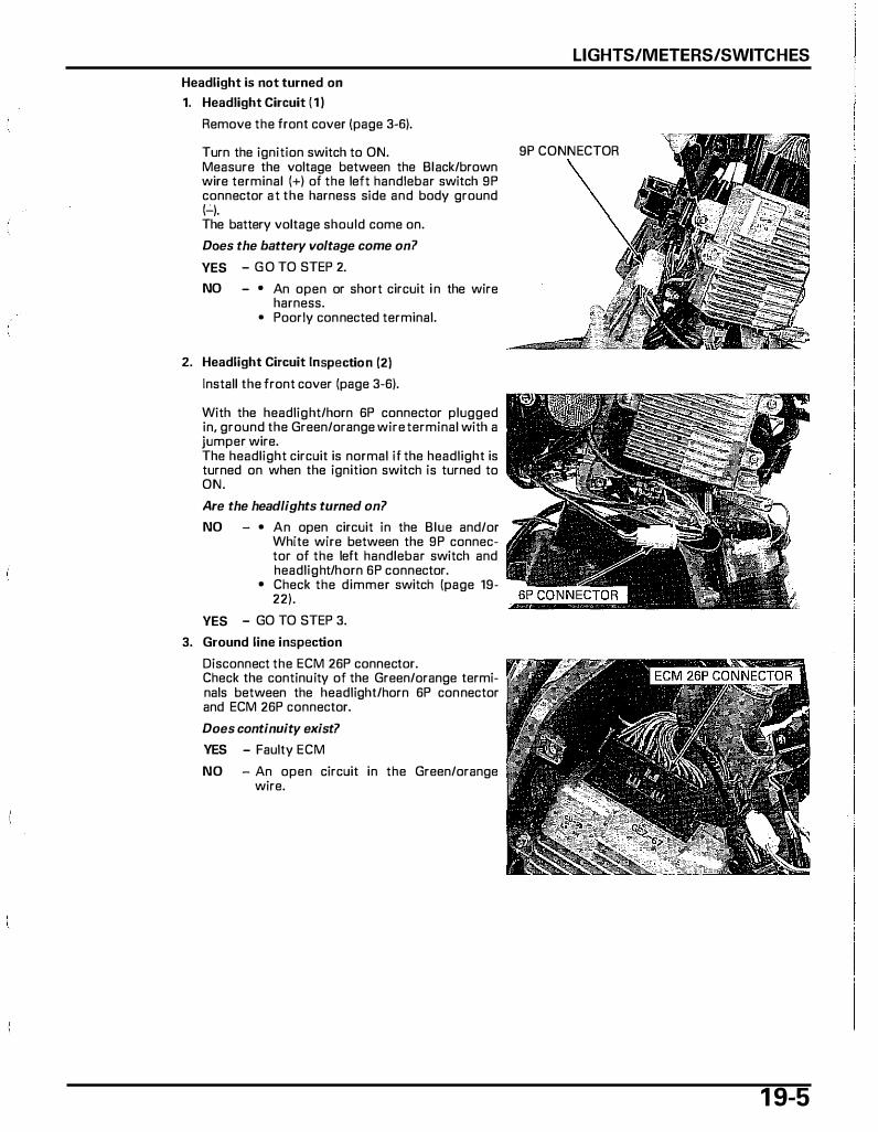
LIGHTS/METERS/SWITCHES
Headlight is not turned on
1. Headlight Circuit { 1 )
Remove the front cover {page 3-6).
Turn the ignition switch to ON. 9P CONNECTOR Measure the voltage between the Black/brown wire terminal {+) of the left handlebar switch 9P connector at the harness side and body ground (-'-). The battery voltage should come on.
Does the battery voltage come on 7
YES - G O TO STEP 2.
NO - • An open or short circuit in the wire harness.
• Poorly connected terminal.
2. Headlight Circuit Inspection {2)
Install the front cover {page 3-6).
With the headlight/horn 6P connector plugged in, ground the Green/orange wire terminal with a jumper wire. The headlight circuit is normal if the headlight is turned on when the ignition switch is turned to ON.
Are the headlights turned on?
NO - • An open circuit in the Blue and/or White wire between the 9P connector of the left handlebar switch and headlight/horn 6P connector.
• Check the dimmer switch {page 19-22).
YES - GO TO STEP 3.
3. Ground line inspection
Disconnect the ECM 26P connector. Check the continuity of the Green/orange terminals between the headlight/horn 6P connector and ECM 26P connector.
Does continuity exist?
YES - Faulty ECM
NO - An open circuit in the Green/orange wire.
1 9-5
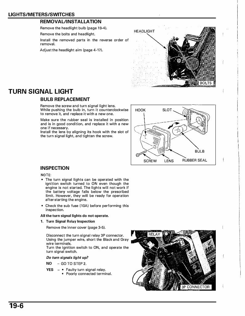
LIGHTS/METERS/SWITCHES
REMOVAL/INSTALLATION
Remove the headlight bulb (page 1 9-4).
Remove the bolts and headlight.
Install the removed parts in the reverse order of removal.
Adjust the headlight aim (page 4-17).
TURN SIGNAL LIGHT
1 9-6
BULB REPLACEMENT
Remove the screw and turn signal light lens. While pushing the bulb in, turn it cou nterclockwise to remove it, and replace it with a new one.
Make sure the rubber seal is installed in position and is in good condition, and replace it with a new one if necessary. Install the lens by aligning its hook with the slot of the turn signal light, and tighten the screw.
INSPECTION
NOTE: • The turn signal lights can be operated with the
ignition switch turned to ON even though the engine is not started. The lights will not work if the battery voltage falls below the prescribed limit. However, they will be ready for operation after starting the engine.
• Check the sub fuse ( 1 0A) before performing this inspection.
All the turn signal lights do not operate.
1 . Turn Signal Relay Inspection
Remove the inner cover (page .3-5).
Disconnect the turn signal relay 3P connector. Using the jumper wire, short the Black and Gray wire terminals. Turn the ignition switch to ON, and operate the turn signal switch.
Do turn signals tight up?
NO - GO TO STEP 2.
YES - • Faulty turn signal relay. • Poorly connected terminal.
HEADLIGHT
HOOK SLOT
BULB
SCREW LENS RUBBER SEAL
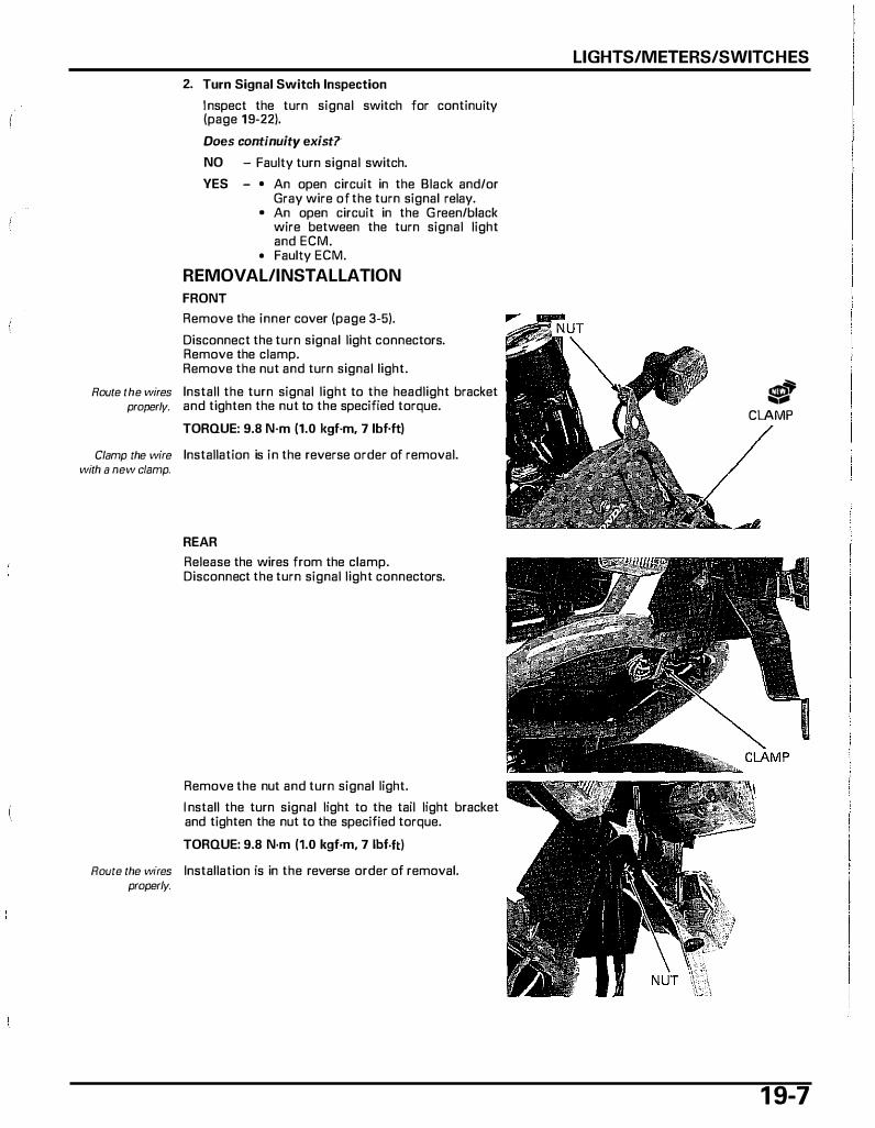
2. Turn Signal Switch Inspection
I nspect the turn signal switch for continuity (page 19-22).
Does continuity exist?·
NO - Faulty turn signal switch.
YES - • An open circuit in the Black and/or Gray wire of the turn signal relay.
• An open circuit in the G reen/black wire between the turn signal light and ECM.
• Faulty ECM.
REMOVAL/INSTALLATION
FRONT
Remove the inner cover (page 3-5).
Disconnect the turn signal light connectors. Remove the clamp. Remove the nut and turn signal light.
Route the wires Install the turn signal light to the headlight bracket properly. and tighten the nut to the specified torque.
TORQUE: 9.8 N·m (1.0 kgf·m, 7 lbf.ft)
Clamp the wire Installation is in the reverse order of removal. with a new clamp.
REAR
Release the wires from the clamp. Disconnect the turn signal light connectors.
Remove the nut and turn signal light.
I nstall the turn signal light to the tail light bracket and tighten the nut to the specified torque.
TORQUE: 9.8 N·m (1.0 kgf·m, 7 lbf.ft)
Route the wfres Installation is in the reverse order of removal. properly.
LIGHTS/METERS/SWITCHES
� s CLAMP
1 9-7
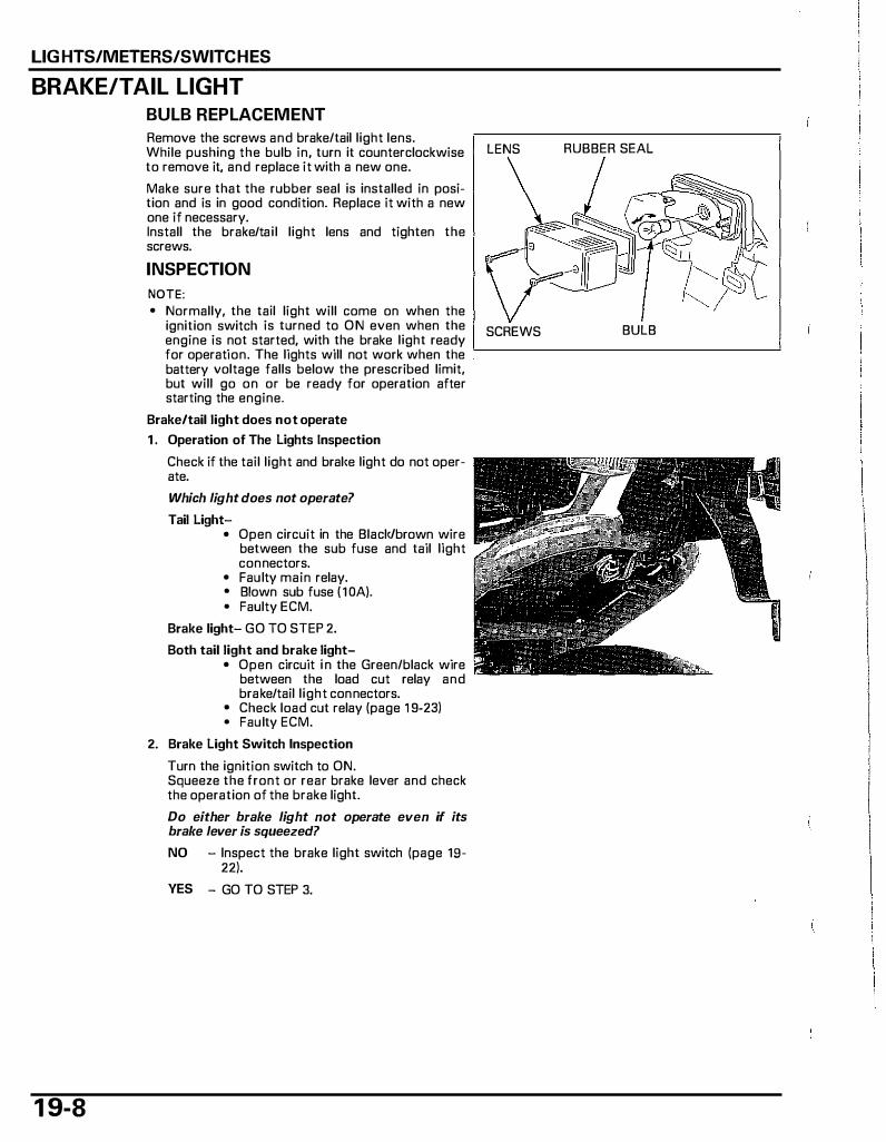
LIGHTS/METERS/SWITCHES
BRAKE/TAIL LIGHT
1 9-8
BULB REPLACEMENT
Remove the screws and brake/tail light lens. While pushing the bulb in, turn it counterclockwise LENS to remove it, and replace it with a new one.
Make sure that the rubber seal is installed in position and is in good condition. Replace it with a new one if necessary. Install the brake/tai l light lens and tighten the screws.
INSPECTION
NOTE: • Normally, the tail light will come on when the
ignition switch is turned to ON even when the SCREWS engine is not started, with the brake light ready for operation. The lights will not work when the battery voltage falls below the prescribed limit, but will go on or be ready for operation after starting the engine.
Brake/tail light does not operate
1 . Operation of The Lights Inspection
Check if the tail light and bral<e light do not operate.
Which light does not operate?
Tail Light-• Open circuit in the Black/brown wire
between the sub fuse and tail light connectors.
• Faulty main relay. • Blown sub fuse (1 0A). • Faulty ECM.
Brake light- GO TO STEP 2.
Both tail light and brake light-• Open circuit i n the Green/black wire
between the load cut relay and brake/tail l ight connectors.
• Check load cut relay (page 1 9-23) • Faulty ECM.
2. Brake Light Switch Inspection
Turn the ignition switch to ON. Squeeze the front or rear brake lever and check the operation of the brake light.
Do either brake light not operate even if its brake lever is squeezed?
NO - Inspect the brake light switch (page 19-22).
YES - GO TO STEP 3.
RUBBER SEAL
BULB
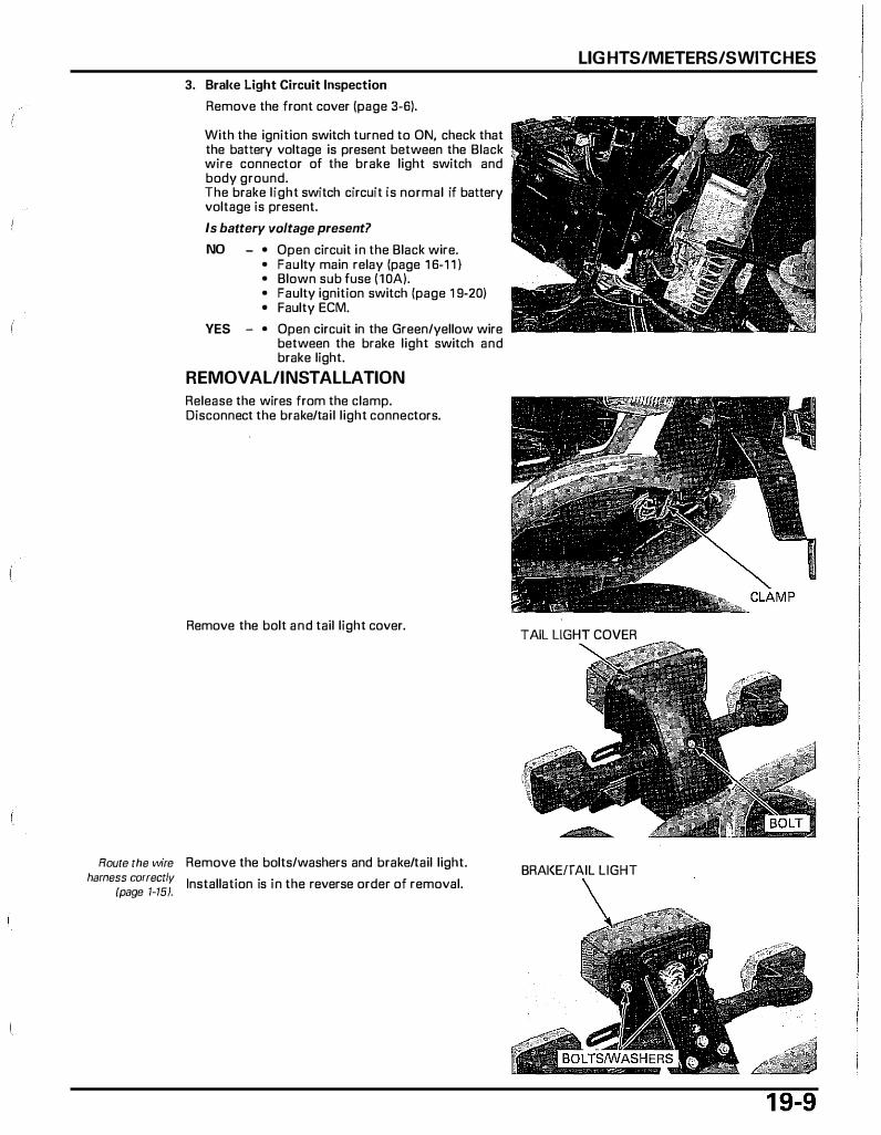
3. Bral<e Light Circuit Inspection
Remove the front cover (page 3-6).
With the ignition switch turned to ON, check that the battery voltage is present between the Black wire connector of the brake light switch and body ground. The brake light switch circuit is normal if battery voltage is present.
Is battery voltage present?
NO - • Open circuit in the Black wire. • Faulty main relay (page 1 6-1 1 ) • Blown sub fuse ( 10A). • Faulty ignition switch (page 1 9-20) • Faulty ECM.
YES - • Open circuit in the Green/yellow wire between the brake light switch and brake light.
REMOVAL/INSTALLATION
Release the wires from the clamp. Disconnect the brake/tail light connectors.
Remove the bolt and tail light cover.
Route the wire Remove the bolts/washers and brake/tail light. harness correctly Installation is in the reverse order of removal.
(page 1-15).
LIGHTS/METERS/SWITCHES
TAIL LIGHT COVER
BRAI<EfTAIL LIGHT
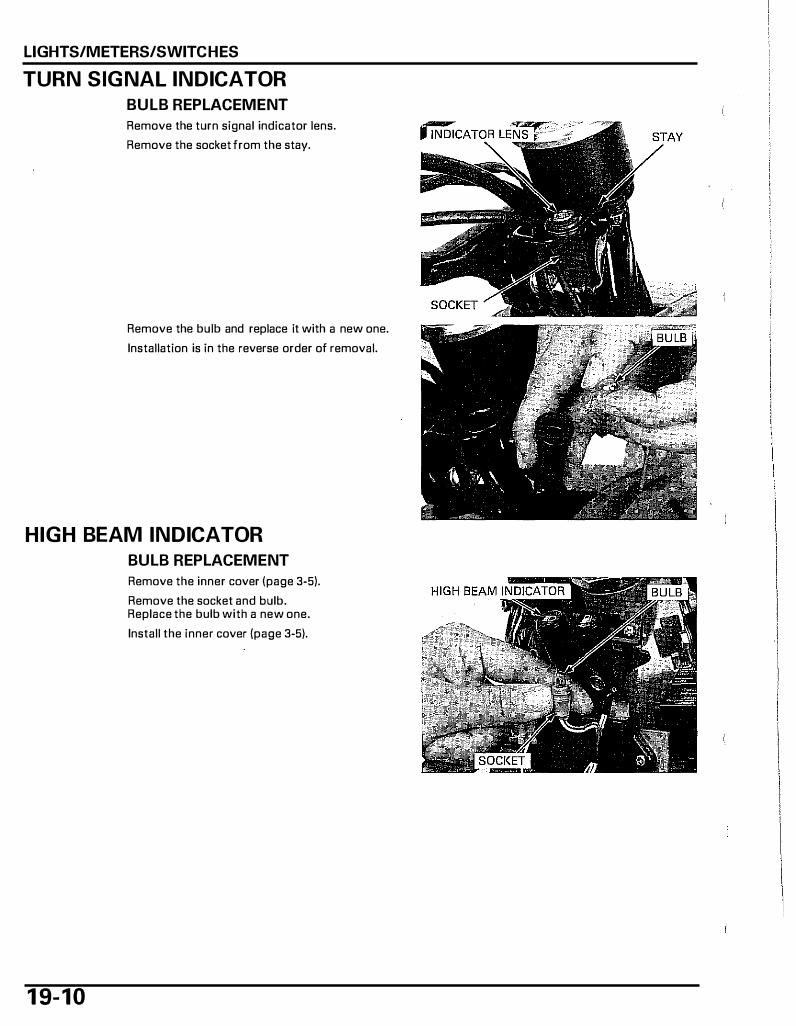
LIGHTS/METERS/SWITCHES
TURN SIGNAL INDICATOR
BULB REPLACEMENT
Remove the turn signal indicator lens.
Remove the socket from the stay.
Remove the bulb and replace it with a new one.
Installation is in the reverse order of removal.
HIGH BEAM INDICATOR
BULB REPLACEMENT
1 9- 1 0
Remove the inner cover I page 3-5).
Remove the socket and bulb. Replace the bulb with a new one.
Install the inner cover I page 3-5).
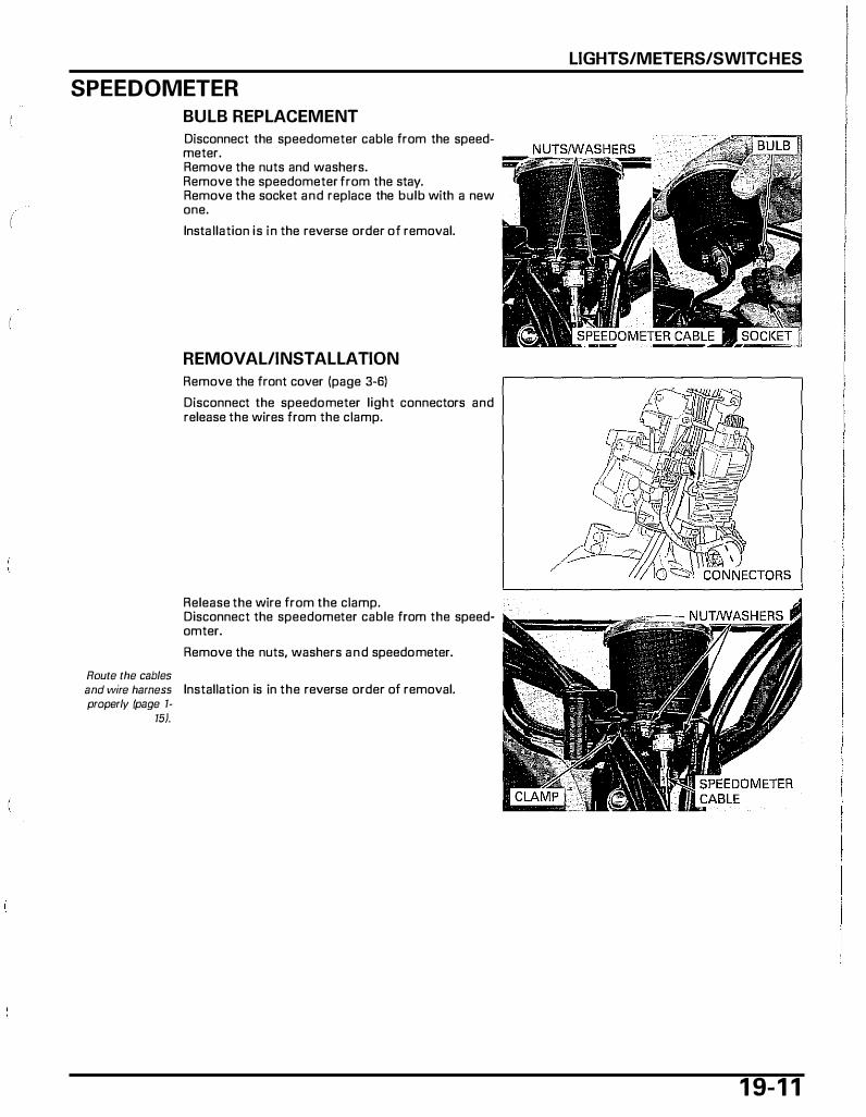
SPEEDOMETER
Route the cables
BULB REPLACEMENT
Disconnect the speedometer cable from the speedmeter. Remove the nuts and washers. Remove the speedometer from the stay. Remove the socket and replace the bulb with a new one.
lnsta llation is in the reverse order of removal.
REMOVAL/INSTALLATION
Remove the front cover (page 3-6)
Disconnect the speedometer light connectors and release the wires from the clamp.
Release the wire from the clamp. Disconnect the speedometer cable from the speedomter.
Remove the nuts, washers and speedometer.
and wire harness Installation is in the reverse order of removal. properly (page 1-
15).
LIGHTS/METERS/SWITCHES
1 9- 1 1

LIGHTS/METERS/SWITCHES
FUEL RESERVE INDICATOR/FUEL RESERVE SENSOR
1 9- 1 2
LED DRIVE UNIT BATTERY/GROUND LINE INSPECTION
NOTE: • Make sure the following items are normal, before
performing this inspection - Main fuse (20A). sub fuse (1 OA) - Main relay (page 1 6-1 1 ), Load cut relay (page
1 9-23) - Ignition switch (page 1 9-20) - ECM (page 1 6-9)
Remove the inner cover (page 3-5).
Turn the ignition switch to ON.
Measure the voltage between the Black wire terminal of the LED drive unit 6P connector and Ground.
There should be battery voltage only when the ignition switch turns to ON.
If there is no voltage, check for an open or short circuit in the wire harness.
Check the continuity of G reen/black wire between the LED drive unit and load cut relay.
There should be continuity.
SYSTEM INSPECTION
NOTE: • Make sure the battery and ground line of the LED
drive unit is normal, before performing this inspection.
When the fuel reserve indicator does not light.
1 . Fuel Reserve Sensor Line Inspection
Ground the Blue/white wire terminal of the LED drive unit 6P connector with a jumper wire. Turn the ignition switch to ON, check that the fuel reserve indicator lights.
Does the indicator light?
NO - GO TO STEP 2.
YES - • An open circuit in the Blue/white wire between the LED drive unit 6P and fuel reserve sensor.
• An open circuit in the Green/blaclc wire between the fuel reserve sensor and load cut relay.
• Faulty fuel reserve sensor.

2. Fuel Indicator Line Inspection
Ground the Blue/white wire terminal of the 6P Black connector with a jumper wire. Measure the voltage between the Light green (+) and Green/white (-) wire terminals of the fuel reserve indicator 2P connector.
Is there approx. 3V7
NO - Faulty LED drive unit.
YES - Faulty LED.
When the indicator always lights during a operation
1 . Resistor Line Inspection (1)
Turn the ignition switch to ON. Measure the voltage between the Black wire terminal of the resistor 2P connector and Ground.
Does the voltage exist?
NO - Open circuit in the Black wire between the resistor 2P connector and main wire harness.
YES - GO TO STEP 3.
2. Resistor Line Inspection (2)
Check the continuity of Blue/white wire between the resistor and LED drive u nit.
Is there continuity?
NO - Open circuit in wire harness
YES - GO TO STEP 3.
3. Resistor Inspection
Disconnect the resistor 2P connector. Measure the resistance between the Black and Green wire terminals of the resistor 2P connector. STANDARD: 64 - 72 lill (20'C/68'F)
Is the resistance within the standard?
NO - Faulty resistor
YES - • Short circuit in the Blue/white wire. • Faulty fuel reserve sensor.
LIGHTS/METERS/SWITCHES
1 9- 1 3

LIGHTS/METERS/SWITCHES
1 9- 1 4
FUEl RESERVE SENSOR REMOVAl
Remove the floor step (page 3-7).
Disconnect the fuel reserve sensor 3P connector.
Release the wire from the clamp.
Remove the retainer by turning it counterclockwise.
Remove the fuel reserve senso.r, being careful not to
deform or damage the sensor.
Remove the rubber seal.
FUEl RESERVE SENSOR INSTAllATION
Install a new rubber seal to the fuel reserve sensor. Install the sensor by aligning its groove with fuel tank tab.
Install the retainer by turning it clockwise and make sure the arrow on the retainer align with the arrow on the fuel tank.
Clamp the wire.
Connect the fuel reserve sensor 3P connector.
Install the floor step (page 3-7).

COOLANT TEMPERATURE INDICATOR/ ECT SENSOR
NOTE: • When the coolant temperature exceeds 1 20 oc
(248 "F), the coolant temperature indicator will blink. The ECM will then control the ignition and reduce engine speed to 9 mph ( 1 5 km/h). At this time, check the cooling system and engine far leaks or damage. If everything is OK, check the following.
• Make sure the battery and ground line of the LED drive unit is normal (page 19-15), before performing this inspection.
SYSTEM INSPECTION
When the coolant temperature indicator does not light.
1 . Coolant Temperature Indicator Circuit Inspection (1 )
Remov� the inner cover (page 3-5).
Ground the Light green/red wire terminal of the LED drive unit 6P connector with a jumper wire. Turn the ignition switch to ON, check that the indicator lights.
Does the indicator light?
NO - GO TO STEP 2.
YES - GO TO STEP 3.
2. Coolant Temperature Inspection (2)
Indicator
Remove the front cover (page 3-6).
Circuit
Ground the Light green/red wire terminal of the LED drive unit 6P connector with a jumper wire. Measure the voltage between the Pink (+) and Green/blue H wire terminals of the water temperature indicator connectors.
Is there approx. 3V7
NO - GO TO STEP 3.
YES - Faulty LED
LIGHTS/METERS/SWITCHES
COOLANT TEMPERATURE INDICATOR
6P CON
1 9- 1 5

LIGHTS/METERS/SWITCHES
1 9- 1 6
3. ECT Sensor Circuit Inspection
Remove the floor step (page 3-7).
Warm up the engine to normal operating temperature. Stop the engine and disconnect the ECT sensor connector White wire. Ground the white wire with a suitable jumper wire. Start the engine and make sure the indicator lights after 10 seconds.
Does the indicator light?
NO - • An open circuit in the White wire between the ECM and ECT sensor.
• An open circuit in the Light green/red wire between the LED drive unit and ECM.
• Faulty LED drive unit • Faulty ECM.
YES - Inspect the ECT sensor (page 19-17).
When the indicator always lights during a operation
1 . Coolant Temperature Indicator Circuit Inspection (short circuit)
Remove the inner cover (page 3-5).
Turn the ignition switch to ON (engine not started) and check that the indicator lights.
Does the indicator lights?
NO - GO TO STEP 2.
YES - Short circuit of Light green/red wire between the LED drive unit and ECM.
2. ECT Sensor Circuit Inspection
Remove the floor step (page 3-7).
Disconnect the ECT sensor White wire connector. Ground the White wire with a suitable jumper wire. Start the engine, check that the i ndicator lights.
Does the indicator light?
NO - • An open circuit of White wire between the ECM and ECT sensor.
• Faulty ECM.
YES - Inspect the ECT sensor (page 19-17) .
COOLANT TEMPERATURE INDICATOR

Keep all flammable materials away
from the electric heating
element. Wear
ECT SENSOR INSPECTION
Remove the floor step (page 3-7). Drain the coolant from the cooling system (page 7-6).
Disconnect the ECT sensor connector and remove the ECT sensor.
Suspend the ECT sensor in a pan of coolant ( 1 :1 mixture) on an electric heating element and measure the resistance between the ECT sensor terminal and body as the coolant heats up.
NOTE: protective clothing, insulated gloves •
and eye protection.
Soak the ECT sensor in coolant up to its threads with at least 40 mm (1 .57 in) from the bottom of the pan to the bottom of the sensor.
• Keep the temperature constant for 3 minutes before testing. A sudden change of temperature will result in incorrect reading. Do not let the thermometer or ECT sensor touch the pan.
Measure the resistance between the ECT sensor terminal and its threads.
Temperature 50"C (122"F) 130"C (266"F) Resistance 690 860 Q 68 83 Q
If the resistance is out of above range, replace the ECT sensor.
Apply sealant to the ECT sensor threads. Do not apply sealant to the sensor head. I nstall and tighten the ECT sensor.
TORQUE: 10 N·m (1.0 kgf·m, 7 lbf·ft)
Connect the ECT sensor connector.
Fill and bleed the cooling system (page 7-7). Install the floor step (page 3-7).
LIGHTS/METERS/SWITCHES
ECT SENSOR
1 9- 1 7
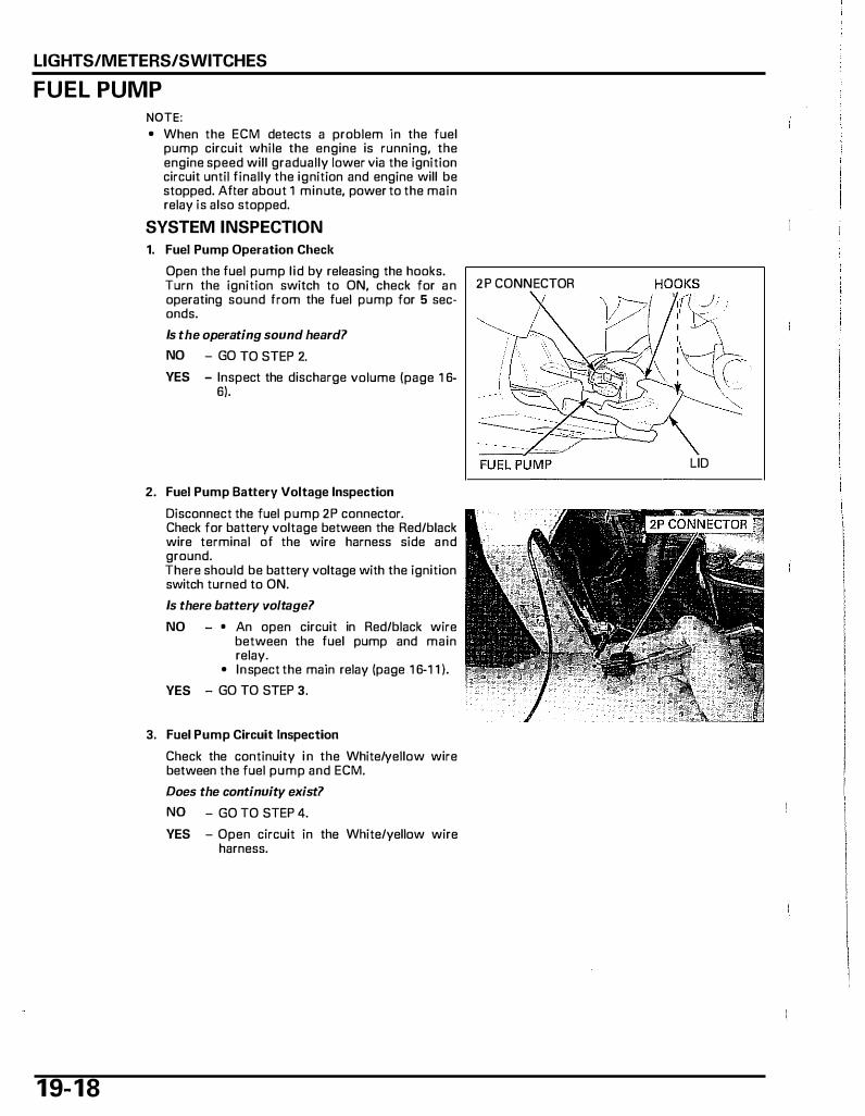
LIGHTS/METERS/SWITCHES
FUEL PUMP
1 9- 1 8
NOTE: • When the ECM detects a problem in the fuel
pump circuit while the engine is running, the engine speed will gradually tower via the ignition circuit until finally the ignition and engine will be stopped. After about 1 minute, power to the main relay is also stopped.
SYSTEM INSPECTION
1. Fuel Pump Operation Check
Open the fuel pump l id by releasing the hooks. Turn the ignition switch to ON, check for an 2P CONNECTOR operating sound from the fuel pump for 5 seconds.
Is the operating sound heard?
NO - GO TO STEP 2.
YES - Inspect the discharge volume (page 1 6-6).
2. Fuel Pump Battery Voltage Inspection
Disconnect the fuel pump 2P connector. Check for battery voltage between the Red/black wire terminal of the wire harness side and ground. There should be battery voltage with the ignition switch turned to ON.
Is there battery voltage?
NO - • An open circuit in Red/black wire between the fuel pump and main relay.
• Inspect the main relay (page 1 6-1 1 ).
YES - GO TO STEP 3.
3. Fuel Pump Circuit Inspection
Check the continuity i n the White/yellow wire between the fuel pump and ECM.
Does the continuity exist?
NO - GO TO STEP 4.
YES - Open circuit in the White/yellow wire harness.
LID
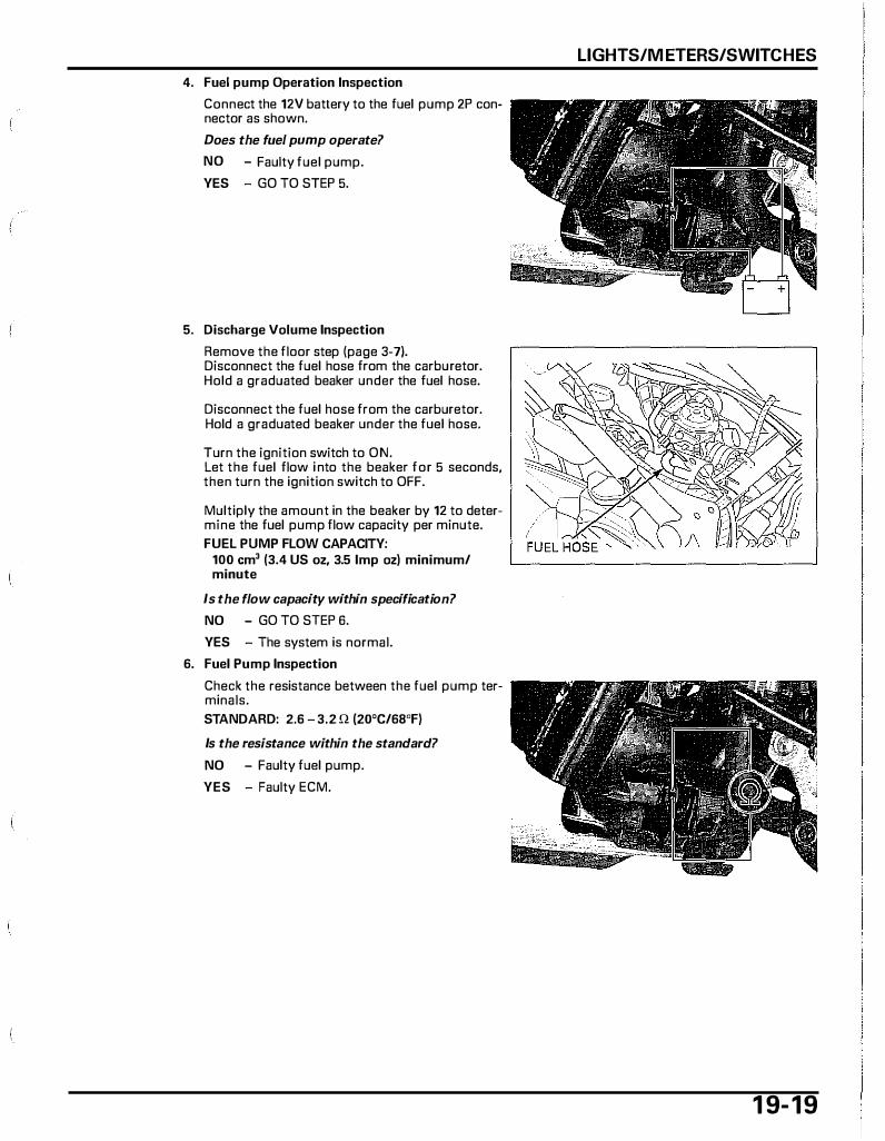
4. Fuel pump Operation Inspection
Connect the 12V battery to the fuel pump 2P connector as shown.
Does the fuel pump operate?
NO - Faulty fuel pump.
YES - GO TO STEP 5.
5. Discharge Volume Inspection
Remove the floor step (page 3-7). Disconnect the fuel hose from the carburetor. Hold a graduated beaker under the fuel hose.
Disconnect the fuel hose from the carburetor. Hold a graduated beaker under the fuel hose.
Turn the ignition switch to ON. Let the fuel flow i nto the beaker for 5 seconds, then turn the ignition switch to OFF.
Multiply the amount in the beaker by 12 to determine the fuel pump flaw capacity per minute. FUEL PUMP FLOW CAPACITY:
100 em' (3.4 US oz, 3.5 Imp oz) minimum/ minute
Is the flow capacity within specification?
NO - GO TO STEP 6.
YES - The system is normal.
6. Fuel Pump Inspection
Check the resistance between the fuel pump terminals. STANDARD: 2.6 - 3.2 n (20'C/68'F)
Is the resistance within the standard?
NO - Faulty fuel pump.
YES - Faulty ECM.
LIGHTS/M HERS/SWITCHES
1 9- 1 9
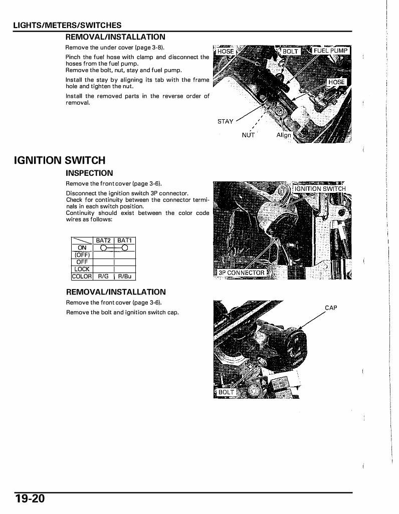
LIGHTS/METERS/SWITCHES
REMOVAL/INSTALLATION
Remove the under cover (page 3-8).
Pinch the fuel hose with clamp and d isconnect the hoses from the fuel pump. Remove the bolt, nut, stay and fuel pump.
Install the stay by aligning its tab with the frame hole and tighten the nut.
Install the removed parts in the reverse order of removal.
IGNITION SWITCH
INSPECTION
1 9-20
Remove the front cover (page 3-6).
Disconnect the ignition switch 3P connector. Check for continuity between the connector terminals in each switch position. Continuity should exist between the color code wires as follows:
...____ BAT2 BAT1 ON r
(OFF) OFF
LOCK COLOR RIG R/Bu
REMOVAL/INSTALLATION
Remove the front cover (page 3-6).
Remove the bolt and ignition switch cap. CAP

Disconnect the ignition switch 3P connector. Remove the two screws and ignition switch.
Use the new screws and install the removed parts in the reverse order of removal.
HANDLEBAR SWITCHES Remove the front cover (page 3-6).
Disconnect the right handlebar switch 4P connector and left handlebar switch 9P connector. Check for continuity between the connector terminals in each switch position. Continuity should exist between the color code wires as shown in the charts below.
LIGHTS/METERS/SWITCHES
1 9-21
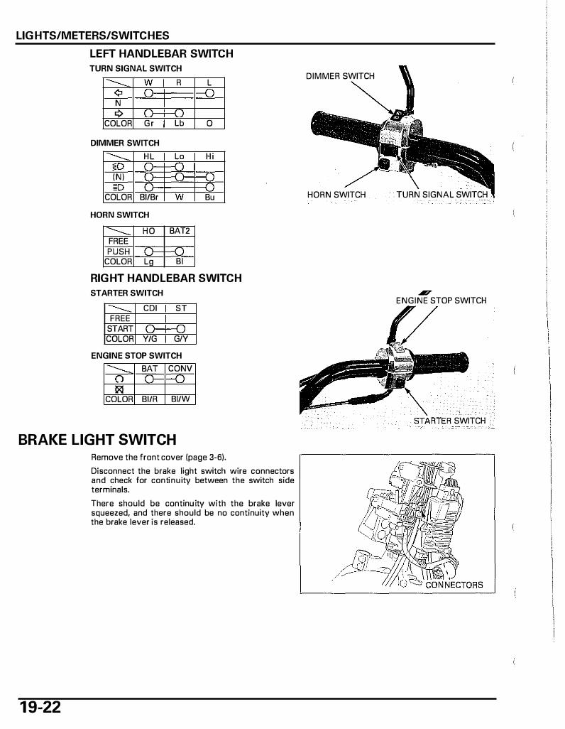
LIGHTS/METERS/SWITCHES
LEFT HANDLEBAR SWITCH
TURN SIGNAL SWITCH
------ w R L ¢ J N 9 )- -n
COLOR G r Lb 0
DIMMER SWITCH
------ H L Lo H i l!D --n (N) r--
D J COLOR 81/Br w Bu
HORN SWITCH
------ HO BAT2 FREE PUSH l)--f-0
COLOR Lg Bl
RIGHT HANDLEBAR SWITCH
STARTER SWITCH
------ CDI ST FREE
START o--o COLOR Y/G GIY
ENGINE STOP SWITCH
--- BAT CONV 0 ( J !1<l
COLOR 81/R 81/W
BRAKE LIGHT SWITCH
1 9-22
Remove the front cover (page 3-6).
Disconnect the brake light switch wire connectors and check for continuity between the switch side terminals.
There should be continuity with the brake lever squeezed, and there should be no continuity when the brake lever is released.
DIMMER SWITCH
HORN SWITCH TURN SIGNAL SWITCH
.17 ENGINE STOP SWITCH
SWITCH
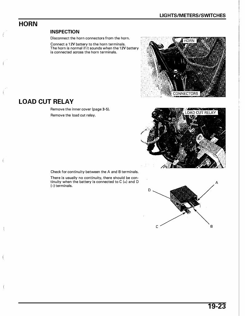
HORN
INSPECTION
Disconnect the horn connectors from the horn.
Connect a 1 2V battery to the horn terminals. The horn is normal if it sounds when the 1 2V battery is connected across the horn terminals.
LOAD CUT RELAY Remove the inner cover (page 3-5).
Remove the load cut relay.
Check for continuity between the A and 8 terminals.
There is usually no continuity, there should be continuity when the battery is connected to C (+) and D (-) terminals.
D
LIGHTS/METERS/SWITCHES
A
c 8
1 9-23
20. WIRING DIAGRAMS
'OS • '05 MOOEL:-·-·-·-·····-········ 20.3 AFTER '05 MOOEL: .. -··-·····---··-··· · �
2 1
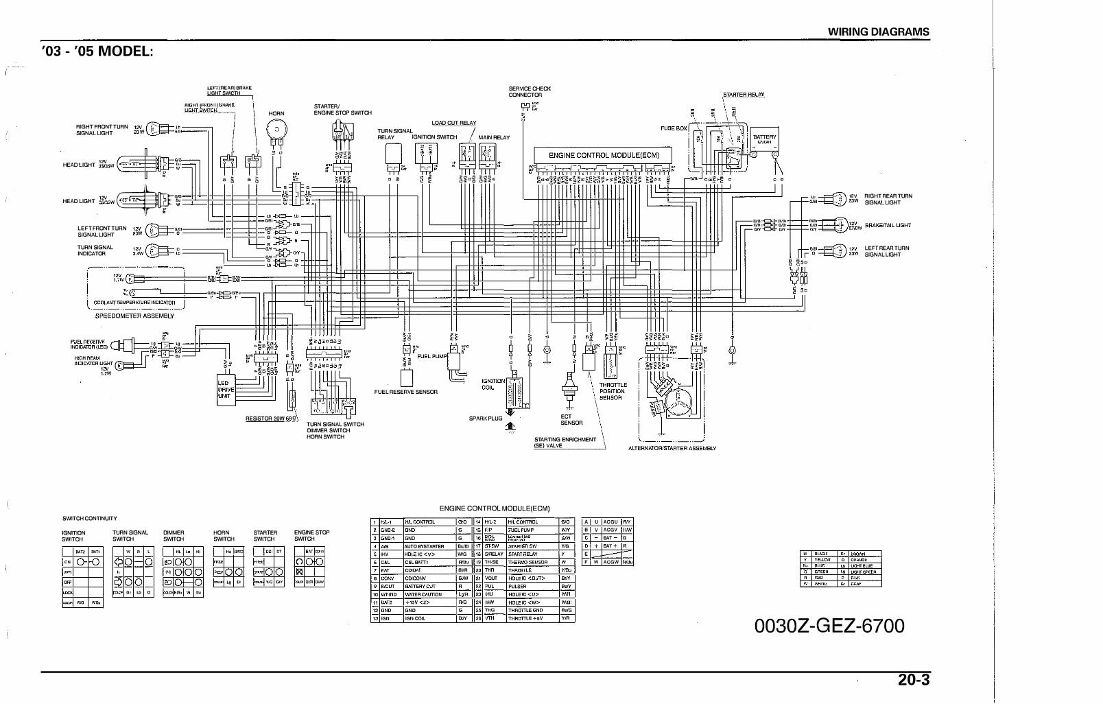
'03 - '05 MODEL:
RIGHT FRONT TURN SIGNAL LIGHT
HEAD LIGHT J�w
HEAD LIGHT � .:; LEFT FRONT TURN l�wV �G(jl SIGNAL LIGHT "" � TURN SIGNAL INDICATOR
SWITCH CONTINUITY
'
--
IGNITION SWITCH
TURN SIGNAL SWITCH
DIMMER SWITCH
aA"fi! BATl w " ' "' �
m• I O -o liD �" " 1111 "' "' r-� - "' � 0 _ , �· w
f= � "'"
"'
'"
lEFr (REAR) BRAKE LIGHT SWICTH
HORN STARTER/ ENGINE STOP SWITCH
SERVICE CHECK CONNECTOR
w ! TURN SIGNAL I I LOAD CUT RELAY
tn I �' f RELAY IGNITION SWITCH _ MAIN RELAY
r+f ljf , 0 -��� n nll ... r�wHf!lil., � u;o �·s �� �· � ��m i�i���·!�����iT----io-+0-� � � ��o� ���· �mw:::
0 •
I I U:PO
o a
"' M< M< 0 " L-f--." �� � 0 �
j RESISTOR 20W 68�
FUEL RESERVE SENSOR
SPARI( PLUG
� ECT SENSOR TURN SIGNAL SWITCH
DIMMER SWITCH HORN SWITCH STARTING ENRICHMENT
(SE) VALVE
HORN SWITCH
llo om ffi�
-
f'• '" "
STARTER SWITCH
'"' "
-
-
= VIG Grf
ENGINE STOP SWITCH
� ="
0 �
= ''" '�
ENGINE CONTROL MODULE(ECM) I""·' � ��� IDND-' IGND-' GND G I" ���" I�.'T>'.:" INS AUTO BYSTARTER '''" I" 1mw ISTAR!ERSW IHV IDLE IC <V> WIG I SIRELAY COL COL BAm ""' I TH-SE
�[ [:��, BVR I THR � ' '"" I VOUT <DUT> '
IHOLE IG< '"' GNO IGN IGN·GO<L I'" ITHROffiE +OV
� IGm I YIG I Y I W l vm, I B<N
I
I YIR
A U B V
c 0 + E ' w
ACGU ""
ACGV FIIW BAT G BAT + A
-
ACGW AlB•
IWElr-c:::J<l-Ell'!lr G/1!1-c:J<:J- Gill I = -=<>- �
WIRING DIAGRAMS
Lll � 12V RIGHT REAR TURN G/81----!::::::::i: 2JW SIGNAL LIGHT
l!l'llr� 12V � �·mew BRAKE!TAILLJGHT
LEFT REAR TURN SIGNAL LIGHT
0030Z -G EZ -6700
20-3
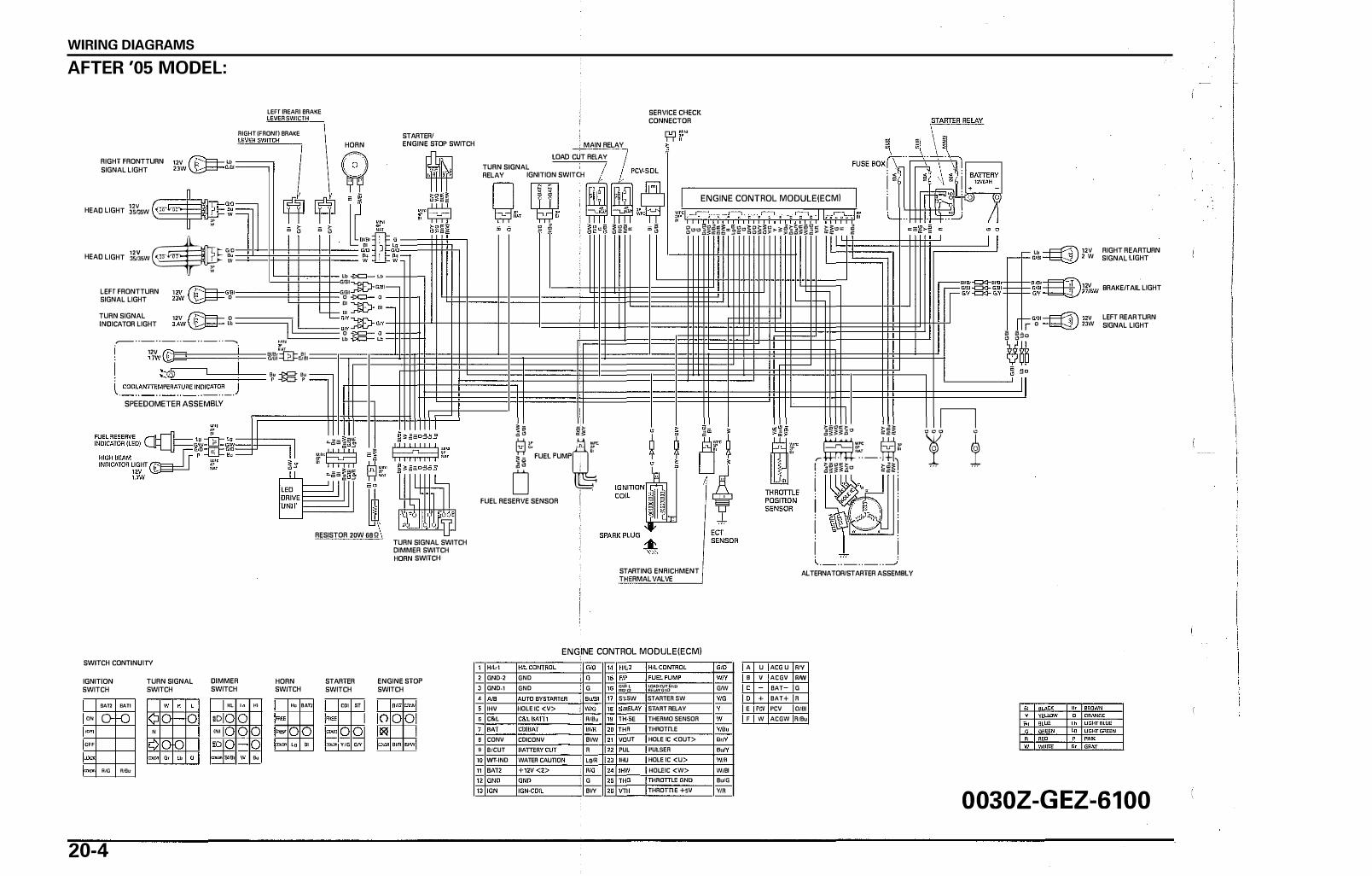
WIRING DIAGRAMS
AFTER '05 MODEL:
LEFT ]REAR) BRAKE LEVER SWICTH
RIGHT (FRONT) BRAKE
RIGHT FRONTTURN m rF'i==>- lli � SIGNAL LIGHT 2'W
�""' I I j HEAD LIGHT ll�sw �:;' '
� - LHJ =
"v $'" HEAD LIGHT ::!SJJSW , �
'" w
LEFT FRONTTURN
SIGNAL LIGHT
"v rF'I==>-om ZJW � O
'
c �
TURN SIGNAL
INDICATOR LIGHT 12V rF'i==>- 0 3.4W � Lb l l
� . . _ .. _ .. _,_ · � l.!l!jl
i 12V �"-=====l'··=== 1fn 1.1w \.Y=]- 't!Hlfllidj��
I :::®"==:t=d== '" -= '" ' !!:... p -t::>C:l- p
l.�����A����ICAT��-.J SPEEDOMETER ASSEMBLY
HORN
Lff •
� c �
"
""' ""'
0 " Lf- ." � , ow 0 "
STARTER/
ENGINE STOP SWITCH
RESISTOR 20W 68 Q
SWITCH CONTINUITY
IGNITION
SWITCH
IIAT2
'" o-'�
"'
"""
- ""
20-4
BAT1
f-0
"'"
TURN SIGNAL
SWITCH
I '
0
DIMMER
SWITCH
"'
OD '"
' m
::ru>n !lli!l!
� "
w '"
HORN
SWITCH
""
""'
-- '"
•m
"
STARTER
SWITCH
COl ST
:nm YIG GIY
TURN SIGNAL SWITCH
DIMMER SWITCH
HORN SWITCH
ENGINE STOP
SWITCH
'" =·
0 ))<! � ·� mm
TURN SIGNAL
MAIN RELAY
lOAD CUT RELAY
RELAY IGNITION SWITCH
SERVICE CHECK
CONNECTOR
; A -.JiA (� ���= c �
ENGINE CONTROL MODULE(ECMI
� � ¥J� � r, FUEL PUMPQ; 0 .
FUEL RESERVE SENSOR I
'iF �=��� §����������o§§�§�>�������� ��o�:: �
STARTING ENRICHMENT
THERMAL VALVE
�����1!1 ���
� �·: ! ���-��1!1 · ·
--���� i ! i I \.._.:,_· _,_, __..
ALTERNATOR/STARTER ASSEMBLY
INE CONTROL MODULE(ECMI ENG! "'"' I "" � )G,ci A U ACG U IW GND·2 GND ! ) G "' I Wrf ' V ACGV IWI GND·> GND ! I G ���� I �J'v".i',:J''IP I G<W c BAT- G "' �� Sf.5W STARTER SW lwo 0 + BAT+ R IHV OLE 1C <V> IW'G SfAOT RELAY E I'CV PCV 0/81 C&L 1 wa. TH·5E THERMO SENSOR lw F w ACGW R/Bu BAT coiBAr I Bim TH" TH,OTTLE l wa" CONV I CDICONV I ""' " VOUl HOLE IC <OUT> l a.!Y BICUT I R PUL PULSER I '"" Wf.IND I WATEO CAU I c,m >HU HOLE IC <U> l wm iAT2 Ti'i2v<2> i "" � HOLEIC <W> W'BI
i IGNO IGND ' G '"'" <)IGN IIGN-COIL "" I 2 6 I VTH THROTTLE +SV WR
" "
Lb � uv RIGHT REAR TURN G!BI� 2JW SIGNAL LIGHT
��!� uv BRAKE!TAIL
.
LIGHT GN �27/BW
r a 2Jw LEFT REAR TURN
SIGNAL LIGHT
� �:So
�55 � ;90
L._ __ __J
n ! ±
0030Z-GEZ-6100

21. TROUBLESHOOTING
ENGINE DOES NOT START OR IS HARD POOR PERFORMANCE AT LOW AND TO START ............................... -.................. 21·2 IDLE SPEE'D··-· ................ .. ........................ _.21·5
ENGINE LACKS POWER·······-·-·········-···· 21-3 POOR PERFORMANCE AT HIGH SPEED-·21·6
POOR HANDLJNG··············· .. ....................... . 21-1
21-1

TROUBLESHOOTING
ENGINE DOES NOT START OR IS HARD TO START
21-2
1. C"Mbutetor Inspection
Chect U1-e fuel flow to 'lhe-catbu r.cor. ,. fwl t�itdtlnfl tM cetbwd'or1
NO Clo-gged tueJ "OM or tuol rittor S6t*inu float valve
• CJoggcd fuel cap bNatbftr • ffulty fvol pump • lo0$e or di!;conmtctad fuel pump aystem wite
VES - GO TO ST£P l.
2. SpatkTest
PttfOfm spark test. t. tho �It goodl NO F11ulty &part phlfil
Fooled ......... F-..<�tyECM Broten Of st'lorctd "*" plug wtre &oa:cn or 5hottJd ignillion aol ��tty Ignition fW tel\ �lly lgnhion putto gtnWMOf Faulty MQi� atop IWltcft Loose c. dltcoruto�ettd lgnltlon svttem wires
V£S - GO TO STEP 3.
3. C')'linder Compression lnsp&etlon
rest 1he cvtindes-compression.
11 the oompr� within apftlf1tllrloJ•1 NO V�Jvc. $ta.Kk ooon
Wem cy1;ncltr tnd pil;ton lingt • le2ting.tdlt.m•Ufd cylindlw htad gnk:et · --• lmpropet .,6),.. tStnlng
Yt:S -GOTOSTEP.t. 4. EnQ:iM StMt Conc[tlon
Stott bv fo!Jowing the normal proODCkirc.
Oou the cnginct sta.rt but Uum JWp•'} YES .. • C.orbwutar lnconoctly edjuotoCI
!nt;;•e m<tnlfold leN!Ino • improper ignition dm!ng (faulty ECM or ignmon pul11t gonentorl • Cont-omlnoUid tueJ • Ft�ulty s11 rtM1g •nrlchmeni.SE) vai'Ve
NO - OOTOST£P ..
5. Spatlc Plug lnsf)cdion Romow: end Inspect the spe.tk Di"'. lolflo __ .. _ _ .,.7 NO Aoooed c:e::buretot
Fwtty s1�ninv en�ne (SE) vatv. Throttle valv9 op�m Air cleanef dirty lncorrecl &part plug 9"P lncor..-c:t s-p;rtl plug noat fll'lge
YES .. Improper ignition timlne lnc:oncct valvt1 cde.tJtonot adjuttmem
ENGINE LACKS POWER 1. Drive Trfllnlnspection
Robe N tront wheel off tM g.-ound 21nd spin lt by Mnd.
.,...tho ___ 1 NO - • 8!8ke dragging
• Wom or d•m.gad wheel bearing• • Bent;)JC�
VES ... 00TOSTEP2. Z. Two PrOKII,.. Inspection
Chedl; lha tJrl prtiSSU(I, IJ the '" ptd.JWe eotr«t., NO - • Faulty tire v.etv•
• Punctured tiro YES - GO TO STEP 4,
3. Dri¥• kt1; tntpeeciofl
Chec;t ltlt drlve bQir wldlb, 1$ tho drlV. belt wirhll within SJ»CirH:tJllool NO - • \\'om Clrlve bill
YES -GO tO STEP •• 4.. Ctlltdl �on
Acce�nne ••pl-dly.
DCHn th• ttngfn� SJH6d chtJnge sccordingfvl
NO Clutch slipping Wom dvtd1 lhOelloutar
• Weak driYoft '•co s:p;ring • Weig"iit'Olloe:ta�
YES - 00 TO ST<P 5. 5. Engine Performane&lnspectlon
Acce'l&rt11 l'ghdy.
DoH rh• •l't9'ine $pHd in<:rMSr! NO Fe� saning .,.ietlmem (SE) wa;w
Clogge,'Cf t�lr cMin41f Aewlcted Nel now Clogged mulrtor Ctoooed ruel cap breather Faulty fwl l)l.lmD hWtv thron:t. posi:tion .,sor
YES - GO TO STEP 8. a. �tit Plug IMPection
Removo •nd lntil)eelll"le spnrfc phtg.
1$ rh� .apri plug lrlgood corrclitiotJJ NO - • Plug not senobd fr�nttv enough
• k'lc:Orrect apart plug beat r;n;• • lncon'ect lplfk ,.U9 gap
YES - GOTO STEP7,
TROUBLESHOOTlNG
21-
TROUBLESHOOTING
21-4
7 . Engine Olt Inspection
Chcct the oil level "nd -condition.
1$ thr: engine o;t in good �;ondltlolll NO - • Oll levei too hlgh
• on level too low • Contamina;ed oil
YES -GOTOSTEPS. 8. lgnitiofl Timing ln;.poctiiQn
C�ck thO ignition timi119.
It; thg ignidon timing '"'ilhln specification?
NO • • Faulty ECM • Faulty Ignition pulse generator • Improper valve timlflO
YES - GO TO STEP 9. 9. Cyl.lnder compression lnspcc;tion
Tes! the cvlinder comprNsion,
Is the comprsssion within $1J(Jr-.ific.J�Hon7 NO - • VDlvc c:lcor�nc!:l tOO !:mall
Worn oylinclcr ;:nd piSlon rings Seited ve l ve lmpreper wtve timing �!dngfdameged cylinder head gasket
YES - GOTOSTEP10.
10. Carburetor 11\spectlon
Check the carburetor for cla..,s.
Is the catburetor clogged?
YES -Carburetor not SMViccd frcqu-ootly enough
NO - GOTOSTEP11.
11.1ubric;nion ln;pcxtion
Remove the c;yllm::ior hc.;:td cover and lnspeC�� for stgns of proper lubrication.
1$ the v<tlv4! tntfn lubrlc.$t«/ properly'!
NO .. Clogged oil passsge
YES - GO TO STEP 12.. 12. Overheati1\Q Inspection
Check f01 engine oyerflesting.
Is the �nglne overheating?
YES - Coolant level too low lhermo&t<Jt $1ut:k cl(ll;lfl';l Exoes&ivtt carbon build·vp in <,:(lmbustion chamber V&c of peorqu;J!itv fuel C!vt<:h S'lipping L.,..n tucl miJCtore
NO ·GOTOSTEP13.
13. Engine Kl'lockinglnspectton
Act:cl.erate or run 81 high &peed.
Is thtt 6ng111� knocklllg?
YES - Worn pls•on and cytinder Wrong type of fuel Excessive carbon bvilcklp in combu$tion chombe:r �nition timing too ;s(lv;'lnc;od lf�vlty ECM) lean fuel mixture
NO Engin� docs not kno::k'
I
I-I I ;I I
POOR PERFORMANCE AT LOW AND IDLE SPEED '· Spark Plug lnspecllon
flernc)w 1nd� the spert ptuv IJ trnt spJ.trlt pJtJg In tood rottdlrion7 NO - • Plug nat lll1VIoecl fftQI.Ie.niiY enough
• tncorrsct •»•rt P'i.ll bM l range • lncorn�ct �>t�aft plug 91;p
YES - GOTOSTEP2. 2. (gnition Timing Inspection
Ch-�X:k the ignition timing. rs tht: ignUkJn t/mln1 within �«lfkltion7
NO - • Feurty £CM • Fauky l,gnltlon !)VIM o•n•tator • lmptopet vtlvo titnn;
V£S - GO TO STEP 3.
l. Catbure-tor pikn sc.nw lnlpeUJon Check the ca;bumor pilot tcr.w .tJustm_ene..
16 t1w ptlot ""wIn th• c:wr«t �1 NO .. Set p,.ge 0..18
YES ... GO TO STEP 4, <4 .. St3rting cnr'ichfl'lenl ISE) Viltvtln.&P4!rtion
Ch�k the �lertlng enrlchmonl (56) v,:vo. 1!1 tht! MJtr61tg Mtlr:hnumr (SE1 v•lv• OK?
NO - Fal!ltv starting Gflrld'lmft (SEt valve
YES - GO TO STEPS. 6. lntat• Manifold a..lld"'t �
Ched for fNb n lfoc lnbllt f"''ooMiklkf and carbura:lor inA!ator.
Does ir 1Hk.1
YES - • LI:IOMinte� m.nitold mouni"ng bolt • o�meo«< l n,u ... tor • D01maged O.rlng
NO -GO TO STEP 6.
&. Sp;;rtt Test
Pel'form spsuk tl!".st.
I!J flu� spatk gtJOd1 NO fallty e1rbon or""'' fouled spart plug
Faulty� Fa:Jity lgnltlon co� Broii!M « ahore.td 1� plug"" f�.Aty englne IIOP� F•uCtv 5crnhfon put. generetot fi:utty lgnttron IWftch Loose or dilc:orwti!CIId Ignition .,-stsm wir8s
YES C.rbl.lrnr not �d frequently enovgh Improperly ldfi,.llod vllve cfe.a�n"
TROUBLESHOOTING
21-5

TROUBLEStiOOTING
POOR PERFORMANCE AT HIGH SPEED
21-6
· · �--... Chockll•lg-�mlng. ... �.--..... "' -' NO • • FiN)(y ECM
• Ftu'1Y ignition put.. oentt1r01 • lmproper'WI!VOIImlng
VES - GOTOSTEP2.
2. fuel Une Inspection
Oisc:oonecl the fuel hose ellhe cnr1Jurclo1,
Oon r/1� fuol flow freely? NO O�ged fu� lint
Oovgad fv.til �p bt'ID1h« • Oogged tu.1 fibr • huley fuel pump • loose Or dbc:ollnKIId kMII pump syttetn lint
Y£9 - GO TO SttP 3.
a. c..tM.tretor Inspection
Rom.ove the carbu tetor end cl\d: for dogged jets.
A,. th• jets �logpd?
YES - Clean the jat9
NO - GOTOSTEP<i.
4. Spark Plug lnspor,.tion
Aemove and inq)ect lht spar!< pluo.
& me ¥M" ptu9 m good CIJ(lc/ltlon7 NO Plug noc �vlced frtqtJ.ntty enough
Jneotn!d 'C)att. piUV Mo-t range • lncotrecl spilt pNg tpp • Faul:y �....-.,.,.(Sf) valve • Alr deaflF!f' dirty
YES -GOTOSTEPS ..
5.. V•tve Timing Inspection Check the v:.tvc liming. J!i tl1e vtJtve timir!g r:orrt�et?
NO - Ct�m sf)rOCktlt not mtt,Hod l)foperty
YES - GOTO$TEI�6.
L V•lve Spring lm;pectlon Check me valw spr'.ngs. Is th• vaMt aprlnglrH t.engih wkhln .,.;£;calion!
NO - Fa-ity vaJ¥e 5Pri'9 YES - GOTOSTEP7.
7. Cemlhm lns;pecdon Remove ond inspe� the umNf'L
'' tht: cam tab• h.;ght wfthln f.Ptclncitlon1
NO - f':a.,�l!y t�msturfl
VES - Olm!lhart i$ OK
1
I

POOR HANDLING Steertno I.J h .. vy • Steerlnv top cone race too Ugh I • OamO'IQ*I CLOP ring bud blartngs
---e-........... m-. P'IY Bent tim
• E)reesalvotv warn engine mo\lntlng bushing • Bent frllmo The seooUtr IIIUMitO one tJcM
R'Ofllland 1t.ar wbeel not M:UNd Fili'Jfty �\ ab5od"bct Sont toltc Sent IX!O Bani trarnt
TROUBLESHOOT I NG
21-7

AIR CLEANER 4·5 AlA C LEANER HOUSING ....... -........... ".-.............. _ .. , , 6-5 ALTERNATOR CHARGING COIL .................................. l6>8 AlTERNATORIS'rARTER ............................................... t2•4 HATTERY ...................................................................... , 1H BATIERYICI-IARGING SYSTEM $PECIACATIONS-····· 1·g BU.Rl.'IG REPI.ACEIIENT -----··----- 1 't.S BEl. T CASH®�A 1o.e 80DY PANEl t.OCATIONS--------·3-2 BitAKE UGKf SWfT'Ctot --··-··-· .................. -... - 19·22 OAAKE LOCK OPERATION ............ " ............................. 4-18 onAK.E SHOESWE'AA ................................................... 4-16 DRAKE SYSTEM ............................ ,.,,,,,.,.,,,,,,, ................ 4-18 BRAKEITAtL. OOHT ,,.,,,_, ............................................. 18-8 CABlE & HARNESS Aot.mNG ·----·---· \•15 CAMSHAFT�ARMI!\J'STAUA"'ON----9-11 CAMSHAFJI1l()(:keR ARMS REMOVAl-·- 9-7 CARBURETOR ASSEMBl.Y -···-----··-·&.12 CARBURETOR DISASSEMBLY ····----···-···-····--···1>8 CARBURETOR INSTAti.AnoN--.. ·····-···-··-·········--· 0.19 CAIIOUAETOO REMOVAl. ·-··········································· 6-7 CHARGING SYSTEM INSPECTIQN ................ -............ tB-7 CLUTCHIDRIVEN Pt.ll.LEV ·--.. -·--·-.. ·-···--··-.... ·1�12 OOMflONENT l.OCAT'IONS
A.LTER.HA.l'ORISTAATER- 12 2 CRANKSHAFTIPlS'TOfiUCV'UNOER- --l3·2 CVUNOER HfAONAlVES -·-· .. ··-·-···--·--&-2 ENGINE REJttOVAL/INSTALLAnON ......................... S.2 ANAL REOUCTION·· .............................................. -·11·2 FRONT WHEEUBRAXEJSUSPCNSIONISTEERINO· 14·2 RJCL SYSTEM .................... -................................. -.• &.2 K ICI<STARTEI\IOI!IVO PULLEY/OO IVEI'I I'V I.LEY/ CWTCM 10.2 1W1R 1MiEE\JilAAWSU SI'ENSIOH - ---15-l
COOLANT ABUCEMENT-·- 7-S COOLANT SVSl<M ltsTING···--····••··•-·,----·-·--····· 7-11 COOlANTTh�PDIAT\JRE INDICATOR/ ECT SENSOR•"''"""""'""'"''"''"'''"" ......................... 19·1S COOUNG SYSTEM ...................................................... 4-\3 COOUNG SYSTEM SPECIFICAllONS-·· .. ··--............... ,...., CRM'KCASC: ASSEM BLY·--·--·--.. -·--·--13·1\ CRANKCASE SEPAAATIOH • 13-5 CRANKS}tAFTIPtSTON 1H CAANKSHAFTil'lSTONICYUI<CER Sl't<:lflCAnONS- 1-& CVUNDeR COMPReSSION TEST·········· .... �·---··-·--· H CVUNDER H� COVEA INSTAllATION .................. 9·22 CYUNOER HEAD COVER REMOVAl ............................. 0-6 CYUNOEA HEAD DISAS$£M9l V ................................ 9·11 CVUNOER HEAD INSTALLA.nON··'"'---··---····-....... 9-18 CYUNCER HEAD At:MOVAL--··----·9-10 CYUND£.q HEAONALVES SI'ECIACAllOf< 1·7 CYUNOEA tiEAO A.SS!MSL V .. --------&-17 OAI'VE PULLEY•• ........... ..._ ........ ----------10o<l EMISSION CONTROL SYSTEMs ............ ,_,, ........... , ... 1•34 ENGINE & FRAME TORQUE VALUf:S ..................... .,.., 1•10 ENGJNE BREATHEfl ·-·· .................................................... �-6 ENG11\'E CONTROL MODULO (ECMI
BA TTERYIOCAAOlNG SYSTEM .. _,,_,, ______ 1&-8 ELB:TIUC STARTER- 1 ,._.
EHGl\'E OOE$ NOT START OR 1$ HAROTOSTART· 21·2 ENGINE !OLf SI'EEI>·-·-···-··-----·----•·ll ENGINE INSTAJ..LATlON· ... ·----· .. ----··· .. -.. -· ·· -- 8·7 ENGINE I.ACKS POWeR .............................................. 21·3 ENGINE OIL .................................................................... 4·10 ENGINE Oil STRAINCA $CREEN·"'"""'"""'""M ........... 4·12 CNGII\'E RE.MOVAI.·---.. ----·-··--·-· ............... _ .. 8-4 FINAL REOUCTlON ASSEMBLY----........ --.. 1 1<1 fiNAL REOUCT10N CMSASSEMBL V • --11-5 FlNAl REDUCTtON Oll.·-----.. ---·--11•5
22. 1NDEX ANALREO Uc:noN SPECIACA110NS 1·7 flOOR STEP···--··--····-·--·········--···-··----····-·· 3-7 FORK ...................................................... -.......... -.... � 14•111 FRONT IJflAKt:·"""""'"""'""'""""'"'""''''"''""''''"'" 1._11 FRONT OOVER .................. ,_ ... _ ........................... -........ 3·6 FRONT WHE£l ........................ -........... � ..... ,_, ____ .. 14·l FRONT WHEEL.AiRAKEISUSPENSIONI$TEERING SIECIACATlONS- 1·8 rua. GAUGEIFU£Ll£VEl SENSOR·-----18-12 AJEl UNE .... -... -·--··-··---.. ------.. 4-4 FUEL PUMP ,,.,., ............. ......................... -....... M .......... 1 9-18 FUEL SYSTEM Sf'ECIFICATIONS• .. ,, ............................. , 1--8 FUEL TANK'"'""""""""""'"""""'-'""""'""""''"""''"'"6·a8 GENERA!. Sr#£C1ACATJOII.'S· ................................ , ... _,,,s HANOLEBAA--· .. • .. -···-··-.. ···--·--.. -......... 1�·\i HNlOLEBAR SWITCHES·- -----·--------18-.21 HEADUGHT Af.L-1.. -------4·1 1 HEADLIGt--n'S----·-------1!1-4 HIOH AllffiJOE AO.JUSTMENT lAftor 'Oti modeU--&-.20 HIGH SEAM tNDICA'rOR--· ........................................ 19·10 HORN ............................................................................. 1&-.2.3 IGNITION COIL ....................................... -.................... 17•7 IGNITION S\f\ITTCH ...................................................... 19 20 IGNffiON SYSH.M INSPECTION---.. ---17<5 IGNillON SYSl<M S?EOFICAllO'<S ----- HI IGNfllON llMING- 11·7 IPONER covEJt ...... ____ ., ___ ·--·---- s-6 ICJCKSTAAT'ER ....................... -............................. -...... IN KICKSTA.ATEMlRIVE PULLEY./ORIVEN PULLEY/ CLUTCH SPECIFICATIONS ..................................... _ ...... 1�1 I.IGHTSJMETEilSJSWITCHES SP£CIACATt0NS """'"'" 1�8 LOAD CUT RELAY ..................................... , _ ,_, ....... 19·ZI WBRICATj()rt iiSEALPCHTS- •1·1l LVSAICATIOH SYSTEM DIAGRAM 5•l LUBIUCATlO'f SYSTEM Sl'iC FICATlONS-- -1·1 MAIN RELAY .. -.. -....... -.-..-------- t&o-11 MAINTENANCE SCHEDULE· .......................................... 4.o3 MODEI. IOENT1FICA llON _,., .......................................... 1•1 MUFFLER ........ 0h .............................................................. 3·9 NIJTS, BOLTS, FASTENERS .......................................... 4·18 Oil PUMp ................... -........ _,_, .. ,., ................... -...... tt-4 PCV (P� CranJcc:Me Ventllatlon ) 1/UIO<'OSmodoll -----l-1 PCVCOHTROL $0 L£ PI.OIO VJIJ...VEI PCV FIE"£0 VALVE. (Ah.M '05 modaU --·--·-........ -.... 6 t4 "LOT SCREW ADJUSTMENT 1'03 • '0!5 modaf) ......... 8·18 PILOT SCREW ADJUSTMENT tAfltlr 'OG modeU"''"" 6•10 POOR HAHOUNG•• ........................................................ 21•7 POOR PEllFORMANCE AT HIGH SI'E!D ·-···-······--·-·· l1·B POOR PERFORMANCE AT LOW A.NO IOl.E SPEED--21-6 RAil!AlOO ----7�12 .. IWliAlOR COO\AHT-----------�-13 RADIATDII RESERVE TANK--···-·---------· 7·14 REAR BRAKE ....... -.... ,.,.,_, __ ,.,._,., ...... M ......... -...... -1S.. REAR SHOCI<. A9SORGER .......................... -............... 16·7 REAR VIHEEL• ................................................................ lfJ·Il REAR WHEEl../8AA!<EISUSPENSK>N SPEctACAnOh."S·-... -..... ___ ..., ___ , _____ , ... ,.a SEAT---·-···------------3-4 SEAT RAil·-�"'- 3 I SECONDARY AlA SUf'f'L V SYSTEM
FUEl SYSTEM -----·---·-·--····-------··-6-22 �.AINTENANC! t'03 • '05 mocW) .............. ,_ .. ,, .. ,_4,1-4 MAJNTENANCS tAtter 'OS modlll•"·'""'"'""""".'"4·15
SERVICE INFORMATION A1. TERNATORISTAATEfl ClliTCJi-................. ,..-... 12·3 BATTERY/CHARGING SVSTEM .. ·-.. ----- t a..l COOLING SY!ITEM------ 7-3 CRA.'MSHAfTIPlSTCINo-'CYUHDEA 13-3
22-1

INDEX
CYUHOEA HIAIWI\LV£S- -----.. - � EUCTRIC STMUR --1W E."<ii GIHE: ftENOYAUf'II!TALLATlOH - &.3 ANAL fBIIUC'Il()N 1 1 -3 mwfJ IIOOY rA,QdlOWJil iYSTE\0-- 3-3 FRJHT WHEBJIA*:ICE.$'SPE-"�<'ST'EtJIKG · 'I<I-3 RJa. SYSrtM S-3 IGHf1lOH S"fS'1'tN 0-3 <ICI<STNIT� ruu.rYQI\'I:N 1'\JU.EY/ CUJTOf lo.l UGH'TSW: EMIS\\I'fT OU �3 Wl!IUCATIOH SYS'Uol s.:J UAINlE"iANCE- 4-2 REAR WH£e1...,11,AA.<itSU&PENSlON 1�
�'Wia R ULES ·-· --·-- -·---·--->-2 SPARK PWO·" •
• -----� SPEEOOMrnA•·• ... ..... ,.., . ., ........................ -·1�11 STANDAAD TOAOUr VI\LUCS ............. _ .............. 1·10 STAimR ACLI\V"'""'"'"""""' ................................. 18-6 STARTING ENfl'CHMCNT !Sa) VA.V( ....................... 641 STEERING HI.'AO OUMINOU ....................................... 4•19 STEERING SlliM•""'"'''""'""'"''""""'""'""""' .. ''' ....... l<t.-23 STEP Fl�""""""'""'" .. "''"''''''"'"'"'"''"""'_ ......... -... 3-a SUSPENSION ...................................... " .............. -.• ·-·4-17 SYSTEM DIAGRAM
BATT£RV/CHAAOINO SVS1'£M ....... . ···--·-··-1&2 EUCTFIC 6TAA1"iR ••• .. ,.,.. . ...... ,.,. ____ .. -1&-2 IGHITIOH SYS'I(M- ·- ----- -· 17·2
SYSTiM R.OW PATTlRH CXXX.I� SVS'T[M-- 1�
2 .
SYSTE M LOCA 'ION LIGH'T�RSISwm:HE8 -----15-2
TliMOTill CJif'IMTN)N --c....4 nwmu POSrr\001 Sf N$010 n.e TN)UMfSMCVJtlMI
BAntJIY04AIIIOI:'IrO SYSlBl 166 COCUIO� >4 0\I.N UtW'T� \ 3-4 C'IU� DEII HlAIWAlVU � U.EC"TM: ST Aft'TDt \&4 ANAl ftS)UC'T10tf. 1� ........aovr�SYSTBO 33 A'IOHT WHEilJ'IAAJCf.IIP'f.NSION"S'TEERING •1<&-e RIEL SYSllM 6 .. rGN�IlON IYI"T'ltll - ·---·----n� KICICSTAA11:Ml�l\lf rouu.tYIOIIMN PUu.EY/ CLUTCH HO· .. ···�-·-�····· ...... -............................ ,_, ___ 1D-fi lUBRICATION SVSTEM •••••••••••••••··--·-·····fN REAR WHEEUORI\I(EIBUBPCNSION ·············-·····15-S
l1JRN SIGNAL tNtltcATOH•• .. , ... , ................................ 19·10 TlJRN SIGNAL LIOHf ....................................... _.,_ ....... ,g.s u��;oen covsn ................................................................ ,;;..a VALVE CLCAf'IANCC ...... ,,,,, ............................................. 4-8 VAlVE GUIOm 1111'\.ACIMENT· ........................... s.l3 VALVE S!ATtNsr'I!CliONIRIPACINO ............... -.... 9-14 WATER fi'U�,mllllltMlSTAT -·---···-----7·8 WHEILSITIMIS· - ----------<-18 WI'IING DIAORANS
'0:1· ·ao MOO(L -===:=====""' AFT'Eft,. UODll 21).(