Embed Size (px)
Citation preview
SW, 05 APR 2012 to 31 MAY 2012
GENERAL INFORMATION
This Airport/Facility Directory is a Civil Flight Information Publication published and distributed every eight weeks by the U.S.Department of Transportation, Federal Aviation Administration, AeroNav Products, http://aeronav.faa.gov. It is designed foruse with Aeronautical Charts covering the conterminous United States, Puerto Rico and the Virgin Islands.
This directory contains all open to the public airports, seaplane bases and heliports, military facilities, and selected privateuse facilities specifically requested by the Department of Defense (DoD) for which a DoD Instrument Approach Procedure hasbeen published in the U.S. Terminal Procedures Publication. Additionally, this directory contains communications data,navigational facilities and certain special notices and procedures.
Military data contained within this publication is provided by the National Geospatial–Intelligence Agency and is intended toprovide reference data for military and/or joint civil/military airports. Not all military data contained in this publication isapplicable to civil users.
CORRECTIONS, COMMENTS, AND/OR PROCUREMENT
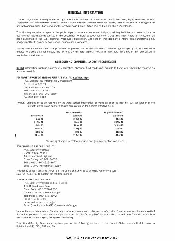
CRITICAL information such as equipment malfunction, abnormal field conditions, hazards to flight, etc., should be reported assoon as possible.
FOR AIRPORT SUPPLEMENT REVISIONS FORM VISIT WEB SITE: http://nfdc.faa.govFAA, Aeronautical Information ManagementNFDC Group AJV–21800 Independence Ave., SWWashington, DC 20591Telephone 1–866–295–8236Fax 202–267–5322
NOTICE: Changes must be received by the Aeronautical Information Services as soon as possible but not later than the‘‘cut-off’’ dates listed below to assure publication on the desired effective date.
Effective DateAirport Information
Cut-off dateAirspace Information*
Cut-off date5 Apr 12 22 Feb 12 2 Feb 12
31 May 12 18 Apr 12 29 Mar 1226 Jul 12 13 Jun 12 24 May 12
20 Sep 12 8 Aug 12 19 Jul 1215 Nov 12 3 Oct 12 13 Sep 1210 Jan 13 28 Nov 12 8 Nov 12
*Including changes to preferred routes and graphic depictions on charts.
FOR CHARTING ERRORS CONTACT:FAA, AeroNav ProductsSSMC–4 Sta. #44451305 East West HighwaySilver Spring, MD 20910–3281Telephone 1–800–626–3677Email 9–AMC–[email protected]
Frequently asked questions (FAQs) are answered on our website at http://aeronav.faa.gov.See the FAQs prior to contact via toll free number.
FOR PROCUREMENT CONTACT:FAA, AeroNav Products Logistics Group10201 Good Luck RoadGlenn Dale, MD 20769–9700Online at http://aeronav.faa.govTelephone 1–800–638–8972Fax 301–436–6829or any authorized chart agent.Email Questions to 9–AMC–[email protected]
New or Changed Information—To alert users of new information or changes to information from the previous issue, a verticalline will be portrayed in the outside margin and extending the full length of the new and/or revised data. This will not apply tothe front cover or the airport/facility directory listing.
This Airport/Facility Directory comprises part of the following sections of the United States Aeronautical InformationPublication (AIP): GEN, ENR and AD.
SW, 05 APR 2012 to 31 MAY 2012
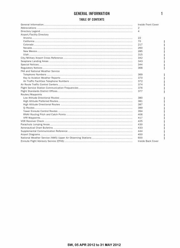
TABLE OF CONTENTSGeneral Information............................................................................................................. Inside Front CoverAbbreviations ..................................................................................................................... 2Directory Legend ................................................................................................................. 4Airport/Facility Directory
Arizona ........................................................................................................................... 22California ........................................................................................................................ 70Colorado ......................................................................................................................... 217Nevada ........................................................................................................................... 260New Mexico..................................................................................................................... 285Utah ............................................................................................................................... 315
City/Military Airport Cross Reference ..................................................................................... 342Seaplane Landing Areas ...................................................................................................... 343Special Notices................................................................................................................... 344Regulatory Notices .............................................................................................................. 368FAA and National Weather Service
Telephone Numbers ......................................................................................................... 369Key to Aviation Weather Reports ........................................................................................ 370Air Traffic Facilities Telephone Numbers ............................................................................. 372
Air Route Traffic Control Centers ........................................................................................... 374Flight Service Station Communication Frequencies .................................................................. 376Flight Standards District Offices............................................................................................ 377Routes/Waypoints
Low Altitude Directional Routes ......................................................................................... 380High Altitude Preferred Routes........................................................................................... 381High Altitude Directional Routes ........................................................................................ 387Q–Routes........................................................................................................................ 389Tower Enroute Control Routes ........................................................................................... 394RNAV Routing Pitch and Catch Points ................................................................................. 406VFR Waypoints................................................................................................................. 417
VOR Receiver Check ............................................................................................................ 425Parachute Jumping Areas ..................................................................................................... 430Aeronautical Chart Bulletins ................................................................................................. 433Supplemental Communication Reference ............................................................................... 444Airport Diagrams ................................................................................................................. 450National Weather Service (NWS) Upper Air Observing Stations .................................................. 600Enroute Flight Advisory Service (EFAS) ................................................................................... Inside Back Cover
GENERAL INFORMATION 1
SW, 05 APR 2012 to 31 MAY 2012
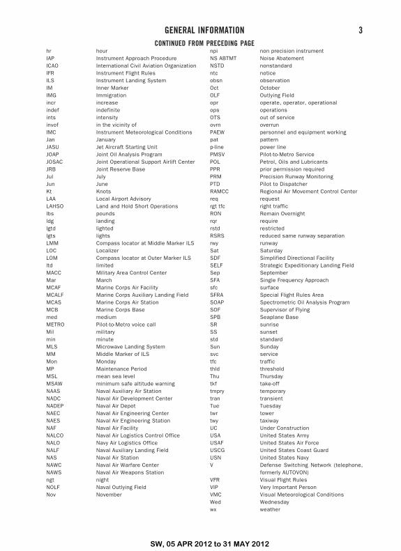
ABBREVIATIONS
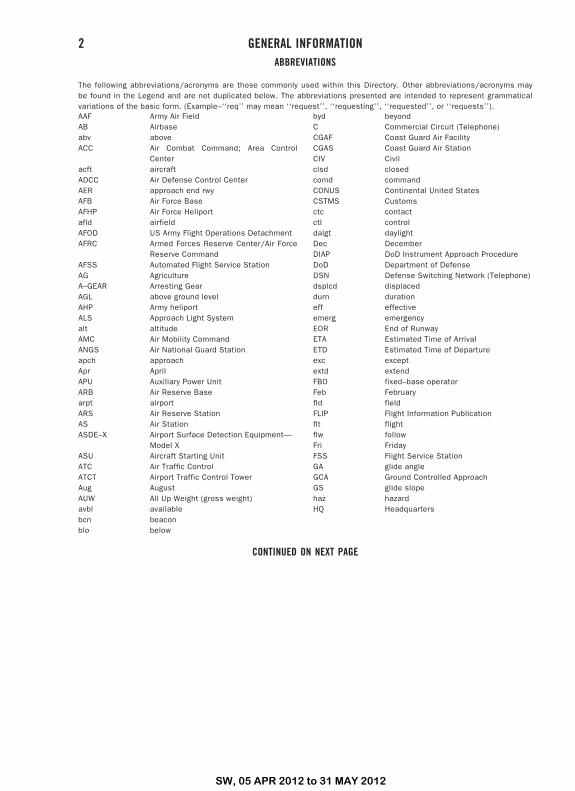
The following abbreviations/acronyms are those commonly used within this Directory. Other abbreviations/acronyms maybe found in the Legend and are not duplicated below. The abbreviations presented are intended to represent grammaticalvariations of the basic form. (Example–‘‘req’’ may mean ‘‘request’’, ‘‘requesting’’, ‘‘requested’’, or ‘‘requests’’).AAF Army Air FieldAB Airbaseabv aboveACC Air Combat Command; Area Control
Centeracft aircraftADCC Air Defense Control CenterAER approach end rwyAFB Air Force BaseAFHP Air Force Heliportafld airfieldAFOD US Army Flight Operations DetachmentAFRC Armed Forces Reserve Center/Air Force
Reserve CommandAFSS Automated Flight Service StationAG AgricultureA–GEAR Arresting GearAGL above ground levelAHP Army heliportALS Approach Light Systemalt altitudeAMC Air Mobility CommandANGS Air National Guard Stationapch approachApr AprilAPU Auxiliary Power UnitARB Air Reserve Basearpt airportARS Air Reserve StationAS Air StationASDE–X Airport Surface Detection Equipment—
Model XASU Aircraft Starting UnitATC Air Traffic ControlATCT Airport Traffic Control TowerAug AugustAUW All Up Weight (gross weight)avbl availablebcn beaconblo below
byd beyondC Commercial Circuit (Telephone)CGAF Coast Guard Air FacilityCGAS Coast Guard Air StationCIV Civilclsd closedcomd commandCONUS Continental United StatesCSTMS Customsctc contactctl controldalgt daylightDec DecemberDIAP DoD Instrument Approach ProcedureDoD Department of DefenseDSN Defense Switching Network (Telephone)dsplcd displaceddurn durationeff effectiveemerg emergencyEOR End of RunwayETA Estimated Time of ArrivalETD Estimated Time of Departureexc exceptextd extendFBO fixed–base operatorFeb Februaryfld fieldFLIP Flight Information Publicationflt flightflw followFri FridayFSS Flight Service StationGA glide angleGCA Ground Controlled ApproachGS glide slopehaz hazardHQ Headquarters
CONTINUED ON NEXT PAGE
2 GENERAL INFORMATION
SW, 05 APR 2012 to 31 MAY 2012
CONTINUED FROM PRECEDING PAGEhr hourIAP Instrument Approach ProcedureICAO International Civil Aviation OrganizationIFR Instrument Flight RulesILS Instrument Landing SystemIM Inner MarkerIMG Immigrationincr increaseindef indefiniteints intensityinvof in the vicinity ofIMC Instrument Meteorological ConditionsJan JanuaryJASU Jet Aircraft Starting UnitJOAP Joint Oil Analysis ProgramJOSAC Joint Operational Support Airlift CenterJRB Joint Reserve BaseJul JulyJun JuneKt KnotsLAA Local Airport AdvisoryLAHSO Land and Hold Short Operationslbs poundsldg landinglgtd lightedlgts lightsLMM Compass locator at Middle Marker ILSLOC LocalizerLOM Compass locator at Outer Marker ILSltd limitedMACC Military Area Control CenterMar MarchMCAF Marine Corps Air FacilityMCALF Marine Corps Auxiliary Landing FieldMCAS Marine Corps Air StationMCB Marine Corps Basemed mediumMETRO Pilot-to-Metro voice callMil militarymin minuteMLS Microwave Landing SystemMM Middle Marker of ILSMon MondayMP Maintenance PeriodMSL mean sea levelMSAW minimum safe altitude warningNAAS Naval Auxiliary Air StationNADC Naval Air Development CenterNADEP Naval Air DepotNAEC Naval Air Engineering CenterNAES Naval Air Engineering StationNAF Naval Air FacilityNALCO Naval Air Logistics Control OfficeNALO Navy Air Logistics OfficeNALF Naval Auxiliary Landing FieldNAS Naval Air StationNAWC Naval Air Warfare CenterNAWS Naval Air Weapons Stationngt nightNOLF Naval Outlying FieldNov November
npi non precision instrumentNS ABTMT Noise AbatementNSTD nonstandardntc noticeobsn observationOct OctoberOLF Outlying Fieldopr operate, operator, operationalops operationsOTS out of serviceovrn overrunPAEW personnel and equipment workingpat patternp-line power linePMSV Pilot-to-Metro ServicePOL Petrol, Oils and LubricantsPPR prior permission requiredPRM Precision Runway MonitoringPTD Pilot to DispatcherRAMCC Regional Air Movement Control Centerreq requestrgt tfc right trafficRON Remain Overnightrqr requirerstd restrictedRSRS reduced same runway separationrwy runwaySat SaturdaySDF Simplified Directional FacilitySELF Strategic Expeditionary Landing FieldSep SeptemberSFA Single Frequency Approachsfc surfaceSFRA Special Flight Rules AreaSOAP Spectrometric Oil Analysis ProgramSOF Supervisor of FlyingSPB Seaplane BaseSR sunriseSS sunsetstd standardSun Sundaysvc servicetfc trafficthld thresholdThu Thursdaytkf take-offtmpry temporarytran transientTue Tuesdaytwr towertwy taxiwayUC Under ConstructionUSA United States ArmyUSAF United States Air ForceUSCG United States Coast GuardUSN United States NavyV Defense Switching Network (telephone,
formerly AUTOVON)VFR Visual Flight RulesVIP Very Important PersonVMC Visual Meteorological ConditionsWed Wednesdaywx weather
GENERAL INFORMATION 3
SW, 05 APR 2012 to 31 MAY 2012
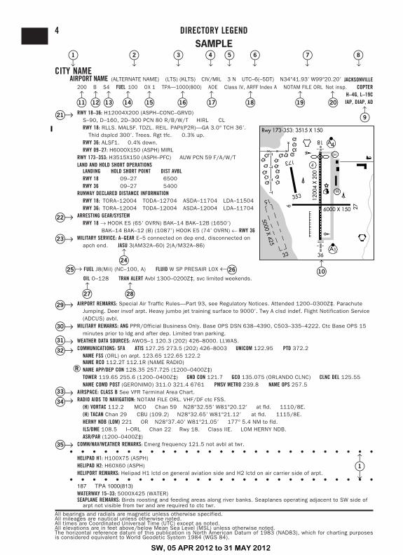
SAMPLE�1 �2 �3 �4 �5 �6 �7 �8
↓ ↓ ↓ ↓ ↓ ↓ ↓ ↓CITY NAME
AIRPORT NAME (ALTERNATE NAME) (LTS) (KLTS) CIV/MIL 3 N UTC–6(–5DT) N34°41.93� W99°20.20� JACKSONVILLE200 B S4 FUEL 100 OX 1 TPA—1000(800) AOE Class IV, ARFF Index A NOTAM FILE ORL Not insp. COPTER
H–4G, L–19CIAP, DIAP, AD�11 �12 �13 �14 �15 �16 �17 �18 �19 �20
↑ ↑ ↑ ↑ ↑ ↑ ↑ ↑ ↑ ↑
�9↑RWY 18–36: H12004X200 (ASPH–CONC–GRVD)
S–90, D–160, 2D–300 PCN 80 R/B/W/T HIRL CLRWY 18: RLLS. MALSF. TDZL. REIL. PAPI(P2R)—GA 3.0° TCH 36�.
Thld dsplcd 300�. Trees. Rgt tfc. 0.3% up.RWY 36: ALSF1. 0.4% down.RWY 09–27: H6000X150 (ASPH) MIRL
RWY 173–353: H3515X150 (ASPH–PFC) AUW PCN 59 F/A/W/TLAND AND HOLD SHORT OPERATIONS
LANDING HOLD SHORT POINT DIST AVBLRWY 18 09–27 6500RWY 36 09–27 5400
RUNWAY DECLARED DISTANCE INFORMATIONRWY 18: TORA–12004 TODA–12704 ASDA–11704 LDA–11504RWY 36: TORA–12004 TODA–12004 ASDA–12004 LDA–11704
ARRESTING GEAR/SYSTEMRWY 18 → HOOK E5 (65� OVRN) BAK–14 BAK–12B (1650�)
BAK–14 BAK–12 (B) (1087�) HOOK E5 (74� OVRN) ← RWY 36MILITARY SERVICE: A–GEAR E–5 connected on dep end, disconnected on
apch end. JASU 3(AM32A–60) 2(A/M32A–86)
↑�24
�25→ FUEL J8(Mil) (NC–100, A) FLUID W SP PRESAIR LOX ←�26OIL O–128 TRAN ALERT Avbl 1300–0200Z‡, svc limited weekends.
↑ ↑�27 �28
�10↑
AIRPORT REMARKS: Special Air Traffic Rules—Part 93, see Regulatory Notices. Attended 1200–0300Z‡. ParachuteJumping. Deer invof arpt. Heavy jumbo jet training surface to 9000�. Twy A clsd indef. Flight Notification Service(ADCUS) avbl.
MILITARY REMARKS: ANG PPR/Official Business Only. Base OPS DSN 638–4390, C503–335–4222. Ctc Base OPS 15minutes prior to ldg and after dep. Limited tran parking.
WEATHER DATA SOURCES: AWOS–1 120.3 (202) 426–8000. LLWAS.COMMUNICATIONS: SFA ATIS 127.25 273.5 (202) 426–8003 UNICOM 122.95 PTD 372.2
NAME FSS (ORL) on arpt. 123.65 122.65 122.2NAME RCO 112.2T 112.1R (NAME RADIO)
�R NAME APP/DEP CON 128.35 257.725 (1200–0400Z‡)TOWER 119.65 255.6 (1200–0400Z‡) GND CON 121.7 GCO 135.075 (ORLANDO CLNC) CLNC DEL 125.55NAME COMD POST (GERONIMO) 311.0 321.4 6761 PMSV METRO 239.8 NAME OPS 257.5
AIRSPACE: CLASS B See VFR Terminal Area Chart.RADIO AIDS TO NAVIGATION: NOTAM FILE ORL. VHF/DF ctc FSS.
(H) VORTAC 112.2 MCO Chan 59 N28°32.55� W81°20.12� at fld. 1110/8E.(H) TACAN Chan 29 CBU (109.2) N28°32.65� W81°21.12� at fld. 1115/8E.HERNY NDB (LOM) 221 OR N28°37.40� W81°21.05� 177° 5.4 NM to fld.ILS/DME 108.5 I–ORL Chan 22 Rwy 18. Class IIE. LOM HERNY NDB.ASR/PAR (1200–0400Z‡)
COMM/NAV/WEATHER REMARKS: Emerg frequency 121.5 not avbl at twr.• • • • • • • • • • • • • • • • • • • • • • • • • • •
HELIPAD H1: H100X75 (ASPH)HELIPAD H2: H60X60 (ASPH)HELIPORT REMARKS: Helipad H1 lctd on general aviation side and H2 lctd on air carrier side of arpt.
• • • • • • • • • • • • • • • • • • • • • • • • • • •187 TPA 1000(813)WATERWAY 15–33: 5000X425 (WATER)SEAPLANE REMARKS: Birds roosting and feeding areas along river banks. Seaplanes operating adjacent to SW side of
arpt not visible from twr and are required to ctc twr.
All bearings and radials are magnetic unless otherwise specified.All mileages are nautical unless otherwise noted.All times are Coordinated Universal Time (UTC) except as noted.All elevations are in feet above/below Mean Sea Level (MSL) unless otherwise noted.The horizontal reference datum of this publication is North American Datum of 1983 (NAD83), which for charting purposesis considered equivalent to World Geodetic System 1984 (WGS 84).
�21→
�22→
�23→
�29→
�30→
�31→�32→
�33→�34→
�35→
�1↑
↓
4 DIRECTORY LEGEND
SW, 05 APR 2012 to 31 MAY 2012
DIRECTORY LEGEND 5
SW, 05 APR 2012 to 31 MAY 2012
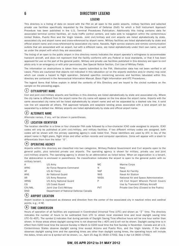
LEGENDThis directory is a listing of data on record with the FAA on all open to the public airports, military facilities and selectedprivate use facilities specifically requested by the Department of Defense (DoD) for which a DoD Instrument ApproachProcedure has been published in the U.S. Terminal Procedures Publication. Additionally this listing contains data forassociated terminal control facilities, air route traffic control centers, and radio aids to navigation within the conterminousUnited States, Puerto Rico and the Virgin Islands. Joint civil/military and civil airports are listed alphabetically by state,associated city and airport name and cross-referenced by airport name. Military facilities are listed alphabetically by state andofficial airport name and cross-referenced by associated city name. Navaids, flight service stations and remote communicationoutlets that are associated with an airport, but with a different name, are listed alphabetically under their own name, as wellas under the airport with which they are associated.
The listing of an open to the public airport in this directory merely indicates the airport operator’s willingness to accommodatetransient aircraft, and does not represent that the facility conforms with any Federal or local standards, or that it has beenapproved for use on the part of the general public. Military and private use facilities published in this directory are open to civilpilots only in an emergency or with prior permission. See Special Notice Section, Civil Use of Military Fields.
The information on obstructions is taken from reports submitted to the FAA. Obstruction data has not been verified in allcases. Pilots are cautioned that objects not indicated in this tabulation (or on the airports sketches and/or charts) may existwhich can create a hazard to flight operation. Detailed specifics concerning services and facilities tabulated within thisdirectory are contained in the Aeronautical Information Manual, Basic Flight Information and ATC Procedures.
The legend items that follow explain in detail the contents of this Directory and are keyed to the circled numbers on thesample on the preceding pages.
�1 CITY/AIRPORT NAMECivil and joint civil/military airports and facilities in this directory are listed alphabetically by state and associated city. Wherethe city name is different from the airport name the city name will appear on the line above the airport name. Airports with thesame associated city name will be listed alphabetically by airport name and will be separated by a dashed rule line. A solidrule line will separate all others. FAA approved helipads and seaplane landing areas associated with a land airport will beseparated by a dotted line. Military airports are listed alphabetically by state and official airport name.
�2 ALTERNATE NAMEAlternate names, if any, will be shown in parentheses.
�3 LOCATION IDENTIFIERThe location identifier is a three or four character FAA code followed by a four-character ICAO code assigned to airports. ICAOcodes will only be published at joint civil/military, and military facilities. If two different military codes are assigned, bothcodes will be shown with the primary operating agency’s code listed first. These identifiers are used by ATC in lieu of theairport name in flight plans, flight strips and other written records and computer operations. Zeros will appear with a slash todifferentiate them from the letter ‘‘O’’.
�4 OPERATING AGENCYAirports within this directory are classified into two categories, Military/Federal Government and Civil airports open to thegeneral public, plus selected private use airports. The operating agency is shown for military, private use and jointcivil/military airports. The operating agency is shown by an abbreviation as listed below. When an organization is a tenant,the abbreviation is enclosed in parenthesis. No classification indicates the airport is open to the general public with nomilitary tenant.A US ArmyAFRC Air Force Reserve CommandAF US Air ForceANG Air National GuardAR US Army ReserveARNG US Army National GuardCG US Coast GuardCIV/MIL Joint Use Civil/MilitaryDND Department of National Defense Canada
MC Marine CorpsN NavyNAF Naval Air FacilityNAS Naval Air StationNASA National Air and Space AdministrationP US Civil Airport Wherein Permit Covers
Use by Transient Military AircraftPVT Private Use Only (Closed to the Public)
�5 AIRPORT LOCATIONAirport location is expressed as distance and direction from the center of the associated city in nautical miles and cardinalpoints, e.g., 4 NE.
�6 TIME CONVERSIONHours of operation of all facilities are expressed in Coordinated Universal Time (UTC) and shown as ‘‘Z’’ time. The directoryindicates the number of hours to be subtracted from UTC to obtain local standard time and local daylight saving timeUTC–5(–4DT). The symbol ‡ indicates that during periods of Daylight Saving Time effective hours will be one hour earlier thanshown. In those areas where daylight saving time is not observed the (–4DT) and ‡ will not be shown. Daylight saving time is ineffect from 0200 local time the second Sunday in March to 0200 local time the first Sunday in November. Canada and all U.S.Conterminous States observe daylight saving time except Arizona and Puerto Rico, and the Virgin Islands. If the stateobserves daylight saving time and the operating times are other than daylight saving times, the operating hours will includethe dates, times and no ‡ symbol will be shown, i.e., April 15–Aug 31 0630–1700Z, Sep 1–Apr 14 0600–1700Z.
6 DIRECTORY LEGEND
SW, 05 APR 2012 to 31 MAY 2012
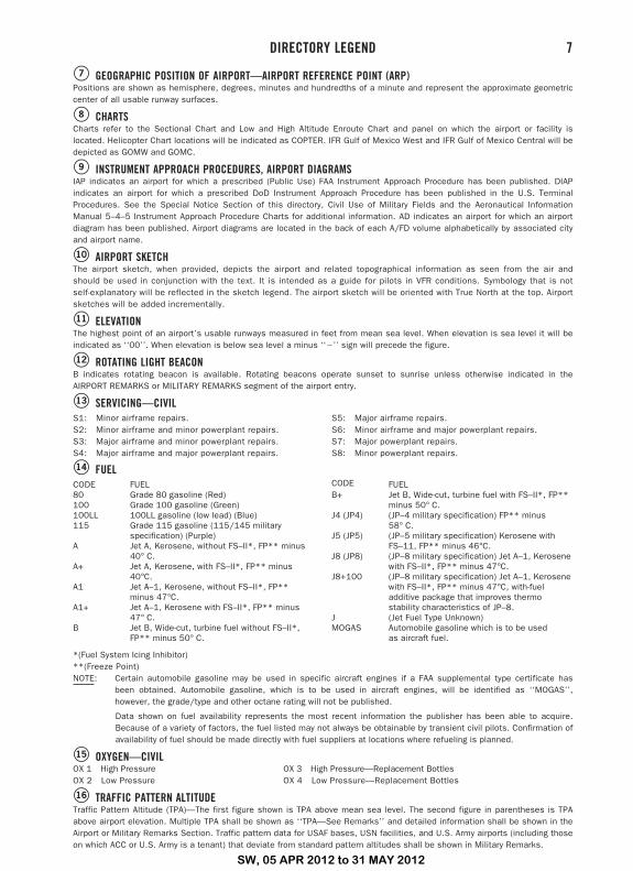
�7 GEOGRAPHIC POSITION OF AIRPORT—AIRPORT REFERENCE POINT (ARP)Positions are shown as hemisphere, degrees, minutes and hundredths of a minute and represent the approximate geometriccenter of all usable runway surfaces.
�8 CHARTSCharts refer to the Sectional Chart and Low and High Altitude Enroute Chart and panel on which the airport or facility islocated. Helicopter Chart locations will be indicated as COPTER. IFR Gulf of Mexico West and IFR Gulf of Mexico Central will bedepicted as GOMW and GOMC.
�9 INSTRUMENT APPROACH PROCEDURES, AIRPORT DIAGRAMSIAP indicates an airport for which a prescribed (Public Use) FAA Instrument Approach Procedure has been published. DIAPindicates an airport for which a prescribed DoD Instrument Approach Procedure has been published in the U.S. TerminalProcedures. See the Special Notice Section of this directory, Civil Use of Military Fields and the Aeronautical InformationManual 5–4–5 Instrument Approach Procedure Charts for additional information. AD indicates an airport for which an airportdiagram has been published. Airport diagrams are located in the back of each A/FD volume alphabetically by associated cityand airport name.
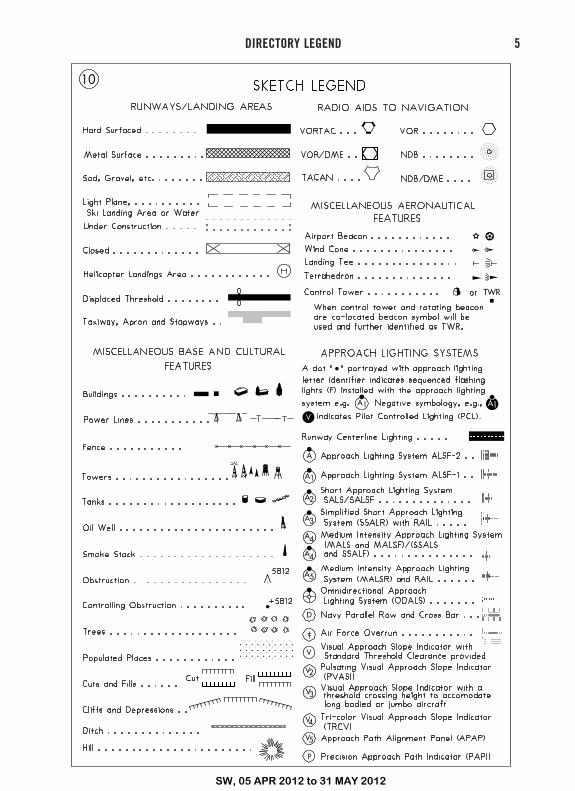
�10 AIRPORT SKETCHThe airport sketch, when provided, depicts the airport and related topographical information as seen from the air andshould be used in conjunction with the text. It is intended as a guide for pilots in VFR conditions. Symbology that is notself-explanatory will be reflected in the sketch legend. The airport sketch will be oriented with True North at the top. Airportsketches will be added incrementally.
�11 ELEVATIONThe highest point of an airport’s usable runways measured in feet from mean sea level. When elevation is sea level it will beindicated as ‘‘00’’. When elevation is below sea level a minus ‘‘�’’ sign will precede the figure.
�12 ROTATING LIGHT BEACONB indicates rotating beacon is available. Rotating beacons operate sunset to sunrise unless otherwise indicated in theAIRPORT REMARKS or MILITARY REMARKS segment of the airport entry.
�13 SERVICING—CIVILS1: Minor airframe repairs.S2: Minor airframe and minor powerplant repairs.S3: Major airframe and minor powerplant repairs.S4: Major airframe and major powerplant repairs.
S5: Major airframe repairs.S6: Minor airframe and major powerplant repairs.S7: Major powerplant repairs.S8: Minor powerplant repairs.
�14 FUELCODE FUEL80 Grade 80 gasoline (Red)100 Grade 100 gasoline (Green)100LL 100LL gasoline (low lead) (Blue)115 Grade 115 gasoline (115/145 military
specification) (Purple)A Jet A, Kerosene, without FS–II*, FP** minus
40° C.A+ Jet A, Kerosene, with FS–II*, FP** minus
40°C.A1 Jet A–1, Kerosene, without FS–II*, FP**
minus 47°C.A1+ Jet A–1, Kerosene with FS–II*, FP** minus
47° C.B Jet B, Wide-cut, turbine fuel without FS–II*,
FP** minus 50° C.
CODE FUELB+ Jet B, Wide-cut, turbine fuel with FS–II*, FP**
minus 50° C.J4 (JP4) (JP–4 military specification) FP** minus
58° C.J5 (JP5) (JP–5 military specification) Kerosene with
FS–11, FP** minus 46°C.J8 (JP8) (JP–8 military specification) Jet A–1, Kerosene
with FS–II*, FP** minus 47°C.J8+100 (JP–8 military specification) Jet A–1, Kerosene
with FS–II*, FP** minus 47°C, with-fueladditive package that improves thermostability characteristics of JP–8.
J (Jet Fuel Type Unknown)MOGAS Automobile gasoline which is to be used
as aircraft fuel.
*(Fuel System Icing Inhibitor)**(Freeze Point)NOTE: Certain automobile gasoline may be used in specific aircraft engines if a FAA supplemental type certificate has
been obtained. Automobile gasoline, which is to be used in aircraft engines, will be identified as ‘‘MOGAS’’,however, the grade/type and other octane rating will not be published.
Data shown on fuel availability represents the most recent information the publisher has been able to acquire.Because of a variety of factors, the fuel listed may not always be obtainable by transient civil pilots. Confirmation ofavailability of fuel should be made directly with fuel suppliers at locations where refueling is planned.
�15 OXYGEN—CIVILOX 1 High PressureOX 2 Low Pressure
OX 3 High Pressure—Replacement BottlesOX 4 Low Pressure—Replacement Bottles
�16 TRAFFIC PATTERN ALTITUDETraffic Pattern Altitude (TPA)—The first figure shown is TPA above mean sea level. The second figure in parentheses is TPAabove airport elevation. Multiple TPA shall be shown as ‘‘TPA—See Remarks’’ and detailed information shall be shown in theAirport or Military Remarks Section. Traffic pattern data for USAF bases, USN facilities, and U.S. Army airports (including thoseon which ACC or U.S. Army is a tenant) that deviate from standard pattern altitudes shall be shown in Military Remarks.
DIRECTORY LEGEND 7
SW, 05 APR 2012 to 31 MAY 2012
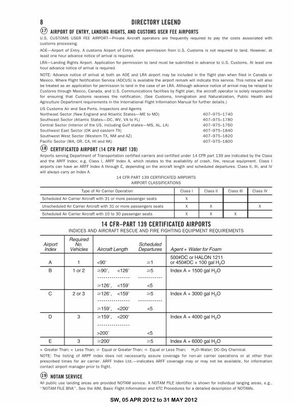
�17 AIRPORT OF ENTRY, LANDING RIGHTS, AND CUSTOMS USER FEE AIRPORTSU.S. CUSTOMS USER FEE AIRPORT—Private Aircraft operators are frequently required to pay the costs associated withcustoms processing.
AOE—Airport of Entry. A customs Airport of Entry where permission from U.S. Customs is not required to land. However, atleast one hour advance notice of arrival is required.
LRA—Landing Rights Airport. Application for permission to land must be submitted in advance to U.S. Customs. At least onehour advance notice of arrival is required.
NOTE: Advance notice of arrival at both an AOE and LRA airport may be included in the flight plan when filed in Canada orMexico. Where Flight Notification Service (ADCUS) is available the airport remark will indicate this service. This notice will alsobe treated as an application for permission to land in the case of an LRA. Although advance notice of arrival may be relayed toCustoms through Mexico, Canada, and U.S. Communications facilities by flight plan, the aircraft operator is solely responsiblefor ensuring that Customs receives the notification. (See Customs, Immigration and Naturalization, Public Health andAgriculture Department requirements in the International Flight Information Manual for further details.)
US Customs Air and Sea Ports, Inspectors and AgentsNortheast Sector (New England and Atlantic States—ME to MD) 407–975–1740Southeast Sector (Atlantic States—DC, WV, VA to FL) 407–975–1780Central Sector (Interior of the US, including Gulf states—MS, AL, LA) 407–975–1760Southwest East Sector (OK and eastern TX) 407–975–1840Southwest West Sector (Western TX, NM and AZ) 407–975–1820Pacific Sector (WA, OR, CA, HI and AK) 407–975–1800
�18 CERTIFICATED AIRPORT (14 CFR PART 139)Airports serving Department of Transportation certified carriers and certified under 14 CFR part 139 are indicated by the Classand the ARFF Index; e.g. Class I, ARFF Index A, which relates to the availability of crash, fire, rescue equipment. Class Iairports can have an ARFF Index A through E, depending on the aircraft length and scheduled departures. Class II, III, and IVwill always carry an Index A.
14 CFR PART 139 CERTIFICATED AIRPORTSAIRPORT CLASSIFICATIONS
Type of Air Carrier Operation Class I Class II Class III Class IV
Scheduled Air Carrier Aircraft with 31 or more passenger seats X
Unscheduled Air Carrier Aircraft with 31 or more passengers seats X X X
Scheduled Air Carrier Aircraft with 10 to 30 passenger seats X X X
14 CFR–PART 139 CERTIFICATED AIRPORTSINDICES AND AIRCRAFT RESCUE AND FIRE FIGHTING EQUIPMENT REQUIREMENTS
AirportIndex
RequiredNo.
Vehicles Aircraft LengthScheduledDepartures Agent + Water for Foam
A 1 <90� �1500#DC or HALON 1211or 450#DC + 100 gal H2O
B 1 or 2 �90�, <126� �5 Index A + 1500 gal H2O---------------- ------------
�126�, <159� <5
C 2 or 3 �126�, <159� �5 Index A + 3000 gal H2O---------------- ------------
�159�, <200� <5
D 3 �159�, <200� Index A + 4000 gal H2O
----------------
>200� <5
E 3 �200� �5 Index A + 6000 gal H2O
> Greater Than; < Less Than; � Equal or Greater Than; � Equal or Less Than; H2O–Water; DC–Dry Chemical.
NOTE: The listing of ARFF index does not necessarily assure coverage for non-air carrier operations or at other thanprescribed times for air carrier. ARFF Index Ltd.—indicates ARFF coverage may or may not be available, for informationcontact airport manager prior to flight.
�19 NOTAM SERVICEAll public use landing areas are provided NOTAM service. A NOTAM FILE identifier is shown for individual langing areas, e.g.,‘‘NOTAM FILE BNA’’. See the AIM, Basic Flight Information and ATC Procedures for a detailed description of NOTAMs.
8 DIRECTORY LEGEND
SW, 05 APR 2012 to 31 MAY 2012
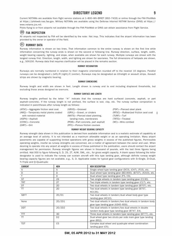
Current NOTAMs are available from flight service stations at 1–800–WX–BRIEF (992–7433) or online through the FAA PilotWebat https://pilotweb.nas.faa.gov. Military NOTAMs are available using the Defense Internet NOTAM Service (DINS) at https://www.notams.jcs.mil.Pilots flying to or from airports not available through the FAA PilotWeb or DINS can obtain assistance from Flight Service.
�20 FAA INSPECTIONAll airports not inspected by FAA will be identified by the note: Not insp. This indicates that the airport information has beenprovided by the owner or operator of the field.
�21 RUNWAY DATARunway information is shown on two lines. That information common to the entire runway is shown on the first line whileinformation concerning the runway ends is shown on the second or following line. Runway direction, surface, length, width,weight bearing capacity, lighting, and slope, when available are shown for each runway. Multiple runways are shown with thelongest runway first. Direction, length, width, and lighting are shown for sea-lanes. The full dimensions of helipads are shown,e.g., 50X150. Runway data that requires clarification will be placed in the remarks section.
RUNWAY DESIGNATION
Runways are normally numbered in relation to their magnetic orientation rounded off to the nearest 10 degrees. Parallelrunways can be designated L (left)/R (right)/C (center). Runways may be designated as Ultralight or assault strips. Assaultstrips are shown by magnetic bearing.
RUNWAY DIMENSIONS
Runway length and width are shown in feet. Length shown is runway end to end including displaced thresholds, butexcluding those areas designed as overruns.
RUNWAY SURFACE AND LENGTH
Runway lengths prefixed by the letter ‘‘H’’ indicate that the runways are hard surfaced (concrete, asphalt, or partasphalt–concrete). If the runway length is not prefixed, the surface is sod, clay, etc. The runway surface composition isindicated in parentheses after runway length as follows:
(AFSC)—Aggregate friction seal coat (GRVD)—Grooved (PSP)—Pierced steel plank(AM2)—Temporary metal planks coated (GRVL)—Gravel, or cinders (RFSC)—Rubberized friction seal coat
with nonskid material (MATS)—Pierced steel planking, (TURF)—Turf(ASPH)—Asphalt landing mats, membranes (TRTD)—Treated(CONC)—Concrete (PEM)—Part concrete, part asphalt (WC)—Wire combed(DIRT)—Dirt (PFC)—Porous friction courses
RUNWAY WEIGHT BEARING CAPACITY
Runway strength data shown in this publication is derived from available information and is a realistic estimate of capability atan average level of activity. It is not intended as a maximum allowable weight or as an operating limitation. Many airportpavements are capable of supporting limited operations with gross weights in excess of the published figures. Permissibleoperating weights, insofar as runway strengths are concerned, are a matter of agreement between the owner and user. Whendesiring to operate into any airport at weights in excess of those published in the publication, users should contact the airportmanagement for permission. Runway strength figures are shown in thousand of pounds, with the last three figures beingomitted. Add 000 to figure following S, D, 2S, 2T, AUW, SWL, etc., for gross weight capacity. A blank space following the letterdesignator is used to indicate the runway can sustain aircraft with this type landing gear, although definite runway weightbearing capacity figures are not available, e.g., S, D. Applicable codes for typical gear configurations with S=Single, D=Dual,T=Triple and Q=Quadruple:
CURRENT NEW NEW DESCRIPTIONS S Single wheel type landing gear (DC3), (C47), (F15), etc.D D Dual wheel type landing gear (BE1900), (B737), (A319), etc.T D Dual wheel type landing gear (P3, C9).ST 2S Two single wheels in tandem type landing gear (C130).TRT 2T Two triple wheels in tandem type landing gear (C17), etc.DT 2D Two dual wheels in tandem type landing gear (B707), etc.TT 2D Two dual wheels in tandem type landing gear (B757,
KC135).SBTT 2D/D1 Two dual wheels in tandem/dual wheel body gear type
landing gear (KC10).None 2D/2D1 Two dual wheels in tandem/two dual wheels in tandem body
gear type landing gear (A340–600).DDT 2D/2D2 Two dual wheels in tandem/two dual wheels in double
tandem body gear type landing gear (B747, E4).TTT 3D Three dual wheels in tandem type landing gear (B777), etc.TT D2 Dual wheel gear two struts per side main gear type landing
gear (B52).TDT C5 Complex dual wheel and quadruple wheel combination
landing gear (C5).
DIRECTORY LEGEND 9
SW, 05 APR 2012 to 31 MAY 2012
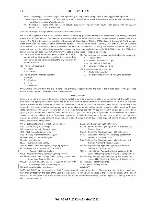
AUW—All up weight. Maximum weight bearing capacity for any aircraft irrespective of landing gear configuration.SWL—Single Wheel Loading. (This includes information submitted in terms of Equivalent Single Wheel Loading (ESWL)
and Single Isolated Wheel Loading).PSI—Pounds per square inch. PSI is the actual figure expressing maximum pounds per square inch runway will
support, e.g., (SWL 000/PSI 535).
Omission of weight bearing capacity indicates information unknown.
The ACN/PCN System is the ICAO standard method of reporting pavement strength for pavements with bearing strengthsgreater than 12,500 pounds. The Pavement Classification Number (PCN) is established by an engineering assessment of therunway. The PCN is for use in conjunction with an Aircraft Classification Number (ACN). Consult the Aircraft Flight Manual,Flight Information Handbook, or other appropriate source for ACN tables or charts. Currently, ACN data may not be availablefor all aircraft. If an ACN table or chart is available, the ACN can be calculated by taking into account the aircraft weight, thepavement type, and the subgrade category. For runways that have been evaluated under the ACN/PCN system, the PCN will beshown as a five-part code (e.g. PCN 80 R/B/W/T). Details of the coded format are as follows:(1) The PCN NUMBER—The reported PCN indicates that an
aircraft with an ACN equal or less than the reported PCNcan operate on the pavement subject to any limitation onthe tire pressure.
(2) The type of pavement:R — RigidF — Flexible
(3) The pavement subgrade category:A — HighB — MediumC — LowD — Ultra-low
(4) The maximum tire pressure authorized for the pavement:W — High, no limitX — Medium, limited to 217 psiY — Low, limited to 145 psiZ — Very low, limited to 73 psi
(5) Pavement evaluation method:T — Technical evaluationU — By experience of aircraft using the pavement
NOTE: Prior permission from the airport controlling authority is required when the ACN of the aircraft exceeds the publishedPCN or aircraft tire pressure exceeds the published limits.
RUNWAY LIGHTING
Lights are in operation sunset to sunrise. Lighting available by prior arrangement only or operating part of the night and/orpilot controlled lighting with specific operating hours are indicated under airport or military remarks. At USN/USMC facilitieslights are available only during airport hours of operation. Since obstructions are usually lighted, obstruction lighting is notincluded in this code. Unlighted obstructions on or surrounding an airport will be noted in airport or military remarks. Runwaylights nonstandard (NSTD) are systems for which the light fixtures are not FAA approved L-800 series: color, intensity, orspacing does not meet FAA standards. Nonstandard runway lights, VASI, or any other system not listed below will be shown inairport remarks or military service. Temporary, emergency or limited runway edge lighting such as flares, smudge pots,lanterns or portable runway lights will also be shown in airport remarks or military service. Types of lighting are shown with therunway or runway end they serve.
NSTD—Light system fails to meet FAA standards.LIRL—Low Intensity Runway Lights.MIRL—Medium Intensity Runway Lights.HIRL—High Intensity Runway Lights.RAIL—Runway Alignment Indicator Lights.REIL—Runway End Identifier Lights.CL—Centerline Lights.TDZL—Touchdown Zone Lights.ODALS—Omni Directional Approach Lighting System.AF OVRN—Air Force Overrun 1000� Standard
Approach Lighting System.MALS—Medium Intensity Approach Lighting System.MALSF—Medium Intensity Approach Lighting System with
Sequenced Flashing Lights.MALSR—Medium Intensity Approach Lighting System with
Runway Alignment Indicator Lights.RLLS—Runway Lead-in Light System
SALS—Short Approach Lighting System.SALSF—Short Approach Lighting System with Sequenced
Flashing Lights.SSALS—Simplified Short Approach Lighting System.SSALF—Simplified Short Approach Lighting System with
Sequenced Flashing Lights.SSALR—Simplified Short Approach Lighting System with
Runway Alignment Indicator Lights.ALSAF—High Intensity Approach Lighting System with
Sequenced Flashing Lights.ALSF1—High Intensity Approach Lighting System with Se-
quenced Flashing Lights, Category I, Configuration.ALSF2—High Intensity Approach Lighting System with Se-
quenced Flashing Lights, Category II, Configuration.SF—Sequenced Flashing Lights.OLS—Optical Landing System.WAVE–OFF.
NOTE: Civil ALSF2 may be operated as SSALR during favorable weather conditions. When runway edge lights are positionedmore than 10 feet from the edge of the usable runway surface a remark will be added in the ‘‘Remarks’’ portion of the airportentry. This is applicable to Air Force, Air National Guard and Air Force Reserve Bases, and those joint civil/military airfields onwhich they are tenants.
10 DIRECTORY LEGEND
SW, 05 APR 2012 to 31 MAY 2012
VISUAL GLIDESLOPE INDICATORS
APAP—A system of panels, which may or may not be lighted, used for alignment of approach path.PNIL APAP on left side of runway PNIR APAP on right side of runway
PAPI—Precision Approach Path IndicatorP2L 2-identical light units placed on left side of
runwayP2R 2-identical light units placed on right side of
runway
P4L 4-identical light units placed on left side ofrunway
P4R 4-identical light units placed on right side ofrunway
PVASI—Pulsating/steady burning visual approach slope indicator, normally a single light unit projecting two colors.PSIL PVASI on left side of runway PSIR PVASI on right side of runway
SAVASI—Simplified Abbreviated Visual Approach Slope IndicatorS2L 2-box SAVASI on left side of runway S2R 2-box SAVASI on right side of runway
TRCV—Tri-color visual approach slope indicator, normally a single light unit projecting three colors.TRIL TRCV on left side of runway TRIR TRCV on right side of runway
VASI—Visual Approach Slope IndicatorV2L 2-box VASI on left side of runwayV2R 2-box VASI on right side of runwayV4L 4-box VASI on left side of runwayV4R 4-box VASI on right side of runway
V6L 6-box VASI on left side of runwayV6R 6-box VASI on right side of runwayV12 12-box VASI on both sides of runwayV16 16-box VASI on both sides of runway
NOTE: Approach slope angle and threshold crossing height will be shown when available; i.e., –GA 3.5° TCH 37�.
PILOT CONTROL OF AIRPORT LIGHTING
Key Mike Function
7 times within 5 seconds Highest intensity available5 times within 5 seconds Medium or lower intensity
(Lower REIL or REIL-Off)3 times within 5 seconds Lowest intensity available
(Lower REIL or REIL-Off)Available systems will be indicated in the airport or military remarks, e.g., ACTIVATE HIRL Rwy 07–25, MALSR Rwy 07, andVASI Rwy 07—122.8.Where the airport is not served by an instrument approach procedure and/or has an independent type system of differentspecification installed by the airport sponsor, descriptions of the type lights, method of control, and operating frequency will beexplained in clear text. See AIM, ‘‘Basic Flight Information and ATC Procedures,’’ for detailed description of pilot control of airportlighting.
RUNWAY SLOPEWhen available, runway slope data will only be provided for those airports with an approved FAA instrument approachprocedure. Runway slope will be shown only when it is 0.3 percent or greater. On runways less than 8000 feet, thedirection of the slope up will be indicated, e.g., 0.3% up NW. On runways 8000 feet or greater, the slope will be shown (upor down) on the runway end line, e.g., RWY 13: 0.3% up., RWY 21: Pole. Rgt tfc. 0.4% down.
RUNWAY END DATAInformation pertaining to the runway approach end such as approach lights, touchdown zone lights, runway endidentification lights, visual glideslope indicators, displaced thresholds, controlling obstruction, and right hand trafficpattern, will be shown on the specific runway end. ‘‘Rgt tfc’’—Right traffic indicates right turns should be made on landingand takeoff for specified runway end.
LAND AND HOLD SHORT OPERATIONS (LAHSO)LAHSO is an acronym for ‘‘Land and Hold Short Operations.’’ These operations include landing and holding short of anintersection runway, an intersecting taxiway, or other predetermined points on the runway other than a runway or taxiway.Measured distance represents the available landing distance on the landing runway, in feet.Specific questions regarding these distances should be referred to the air traffic manager of the facility concerned. TheAeronautical Information Manual contains specific details on hold–short operations and markings.
RUNWAY DECLARED DISTANCE INFORMATION
TORA—Take-off Run Available. The length of runway declared available and suitable for the ground run of an aeroplanetake–off.TODA—Take-off Distance Available. The length of the take–off run available plus the length of the clearway, if provided.ASDA—Accelerate-Stop Distance Available. The length of the take–off run available plus the length of the stopway, if provided.LDA—Landing Distance Available. The length of runway which is declared available and suitable for the ground run of anaeroplane landing.
�22 ARRESTING GEAR/SYSTEMSArresting gear is shown as it is located on the runway. The a–gear distance from the end of the appropriate runway (or into theoverrun) is indicated in parentheses. A–Gear which has a bi–direction capability and can be utilized for emergency approachend engagement is indicated by a (B). The direction of engaging device is indicated by an arrow. Up to 15 minutes advancenotice may be required for rigging A–Gear for approach and engagement. Airport listing may show availability of other than USSystems. This information is provided for emergency requirements only. Refer to current aircraft operating manuals for specificengagement weight and speed criteria based on aircraft structural restrictions and arresting system limitations.
Following is a list of current systems referenced in this publication identified by both Air Force and Navy terminology:
DIRECTORY LEGEND 11
SW, 05 APR 2012 to 31 MAY 2012
BI–DIRECTIONAL CABLE (B)TYPE DESCRIPTION
BAK–9 Rotary friction brake.BAK–12A Standard BAK–12 with 950 foot run out, 1–inch cable and 40,000 pound weight setting. Rotary
friction brake.BAK–12B Extended BAK–12 with 1200 foot run, 1¼ inch Cable and 50,000 pounds weight setting. Rotary
friction brake.E28 Rotary Hydraulic (Water Brake).M21 Rotary Hydraulic (Water Brake) Mobile.
The following device is used in conjunction with some aircraft arresting systems:BAK–14 A device that raises a hook cable out of a slot in the runway surface and is remotely positioned
for engagement by the tower on request. (In addition to personnel reaction time, the systemrequires up to five seconds to fully raise the cable.)
H A device that raises a hook cable out of a slot in the runway surface and is remotely positionedfor engagement by the tower on request. (In addition to personnel reaction time, the systemrequires up to one and one–half seconds to fully raise the cable.)
UNI–DIRECTIONAL CABLE
TYPE DESCRIPTION
MB60 Textile brake—an emergency one–time use, modular braking system employing the tearing ofspecially woven textile straps to absorb the kinetic energy.
E5/E5–1/E5–3 Chain Type. At USN/USMC stations E–5 A–GEAR systems are rated, e.g., E–5 RATING–13R–1100HW (DRY), 31L/R–1200 STD (WET). This rating is a function of the A–GEAR chain weight andlength and is used to determine the maximum aircraft engaging speed. A dry rating applies to astabilized surface (dry or wet) while a wet rating takes into account the amount (if any) of wetoverrun that is not capable of withstanding the aircraft weight. These ratings are published underMilitary Service.
FOREIGN CABLE
TYPE DESCRIPTION US EQUIVALENT
44B–3H Rotary Hydraulic)(Water Brake)
CHAG Chain E–5
UNI–DIRECTIONAL BARRIER
TYPE DESCRIPTION
MA–1A Web barrier between stanchions attached to a chain energy absorber.BAK–15 Web barrier between stanchions attached to an energy absorber (water squeezer, rotary friction,
chain). Designed for wing engagement.
NOTE: Landing short of the runway threshold on a runway with a BAK–15 in the underrun is a significant hazard. The barrierin the down position still protrudes several inches above the underrun. Aircraft contact with the barrier short of the runwaythreshold can cause damage to the barrier and substantial damage to the aircraft.
OTHER
TYPE DESCRIPTIONEMAS Engineered Material Arresting System, located beyond the departure end of the runway, consisting of
high energy absorbing materials which will crush under the weight of an aircraft.
�23 MILITARY SERVICESpecific military services available at the airport are listed under this general heading. Remarks applicable to any militaryservice are shown in the individual service listing.
�24 JET AIRCRAFT STARTING UNITS (JASU)The numeral preceding the type of unit indicates the number of units available. The absence of the numeral indicates tenor more units available. If the number of units is unknown, the number one will be shown. Absence of JASU designationindicates non–availability.
The following is a list of current JASU systems referenced in this publication:
USAF JASU (For variations in technical data, refer to T.O. 35–1–7.)
ELECTRICAL STARTING UNITS:A/M32A–86 AC: 115/200v, 3 phase, 90 kva, 0.8 pf, 4 wire
DC: 28v, 1500 amp, 72 kw (with TR pack)MC–1A AC: 115/208v, 400 cycle, 3 phase, 37.5 kva, 0.8 pf, 108 amp, 4 wire
DC: 28v, 500 amp, 14 kwMD–3 AC: 115/208v, 400 cycle, 3 phase, 60 kva, 0.75 pf, 4 wire
DC: 28v, 1500 amp, 45 kw, split busMD–3A AC: 115/208v, 400 cycle, 3 phase, 60 kva, 0.75 pf, 4 wire
DC: 28v, 1500 amp, 45 kw, split busMD–3M AC: 115/208v, 400 cycle, 3 phase, 60 kva, 0.75 pf, 4 wire
DC: 28v, 500 amp, 15 kw
12 DIRECTORY LEGEND
SW, 05 APR 2012 to 31 MAY 2012
MD–4 AC: 120/208v, 400 cycle, 3 phase, 62.5 kva, 0.8 pf, 175 amp, ‘‘WYE’’ neutral ground, 4 wire, 120v,400 cycle, 3 phase, 62.5 kva, 0.8 pf, 303 amp, ‘‘DELTA’’ 3 wire, 120v, 400 cycle, 1 phase, 62.5kva, 0.8 pf, 520 amp, 2 wire
AIR STARTING UNITSAM32–95 150 +/� 5 lb/min (2055 +/� 68 cfm) at 51 +/� 2 psiaAM32A–95 150 +/� 5 lb/min @ 49 +/� 2 psia (35 +/� 2 psig)LASS 150 +/� 5 lb/min @ 49 +/� 2 psiaMA–1A 82 lb/min (1123 cfm) at 130° air inlet temp, 45 psia (min) air outlet pressMC–1 15 cfm, 3500 psiaMC–1A 15 cfm, 3500 psiaMC–2A 15 cfm, 200 psiaMC–11 8,000 cu in cap, 4000 psig, 15 cfm
COMBINED AIR AND ELECTRICAL STARTING UNITS:AGPU AC: 115/200v, 400 cycle, 3 phase, 30 kw gen
DC: 28v, 700 ampAIR: 60 lb/min @ 40 psig @ sea level
AM32A–60* AIR: 120 +/� 4 lb/min (1644 +/� 55 cfm) at 49 +/� 2 psiaAC: 120/208v, 400 cycle, 3 phase, 75 kva, 0.75 pf, 4 wire, 120v, 1 phase, 25 kvaDC: 28v, 500 amp, 15 kw
AM32A–60A AIR: 150 +/� 5 lb/min (2055 +/� 68 cfm at 51 +/� psiaAC: 120/208v, 400 cycle, 3 phase, 75 kva, 0.75 pf, 4 wireDC: 28v, 200 amp, 5.6 kw
AM32A–60B* AIR: 130 lb/min, 50 psiaAC: 120/208v, 400 cycle, 3 phase, 75 kva, 0.75 pf, 4 wireDC: 28v, 200 amp, 5.6 kw
*NOTE: During combined air and electrical loads, the pneumatic circuitry takes preference and will limit the amount ofelectrical power available.USN JASUELECTRICAL STARTING UNITS:NC–8A/A1 DC: 500 amp constant, 750 amp intermittent, 28v;
AC: 60 kva @ .8 pf, 115/200v, 3 phase, 400 Hz.NC–10A/A1/B/C DC: 750 amp constant, 1000 amp intermittent, 28v;
AC: 90 kva, 115/200v, 3 phase, 400 Hz.AIR STARTING UNITS:GTC–85/GTE–85 120 lbs/min @ 45 psi.MSU–200NAV/A/U47A–5 204 lbs/min @ 56 psia.WELLS AIR STARTSYSTEM
180 lbs/min @ 75 psi or 120 lbs/min @ 45 psi. Simultaneous multiple start capability.
COMBINED AIR AND ELECTRICAL STARTING UNITS:NCPP–105/RCPT 180 lbs/min @ 75 psi or 120 lbs/min @ 45 psi. 700 amp, 28v DC. 120/208v, 400 Hz AC,
30 kva.
JASU (ARMY)59B2–1B 28v, 7.5 kw, 280 amp.
OTHER JASU
ELECTRICAL STARTING UNITS (DND):CE12 AC 115/200v, 140 kva, 400 Hz, 3 phaseCE13 AC 115/200v, 60 kva, 400 Hz, 3 phaseCE14 AC/DC 115/200v, 140 kva, 400 Hz, 3 phase, 28vDC, 1500 ampCE15 DC 22–35v, 500 amp continuous 1100 amp intermittentCE16 DC 22–35v, 500 amp continuous 1100 amp intermittent soft start
AIR STARTING UNITS (DND):CA2 ASA 45.5 psig, 116.4 lb/min
COMBINED AIR AND ELECTRICAL STARTING UNITS (DND)CEA1 AC 120/208v, 60 kva, 400 Hz, 3 phase DC 28v, 75 amp
AIR 112.5 lb/min, 47 psig
ELECTRICAL STARTING UNITS (OTHER)C–26 28v 45kw 115–200v 15kw 380–800 Hz 1 phase 2 wireC–26–B, C–26–C 28v 45kw: Split Bus: 115–200v 15kw 380–800 Hz 1 phase 2 wireE3 DC 28v/10kw
AIR STARTING UNITS (OTHER):A4 40 psi/2 lb/sec (LPAS Mk12, Mk12L, Mk12A, Mk1, Mk2B)MA–1 150 Air HP, 115 lb/min 50 psiaMA–2 250 Air HP, 150 lb/min 75 psia
CARTRIDGE:MXU–4A USAF
DIRECTORY LEGEND 13
SW, 05 APR 2012 to 31 MAY 2012
�25 FUEL—MILITARYFuel available through US Military Base supply, DESC Into–Plane Contracts and/or reciprocal agreement is listed first and isfollowed by (Mil). At commercial airports where Into–Plane contracts are in place, the name of the refueling agent is shown.Military fuel should be used first if it is available. When military fuel cannot be obtained but Into–Plane contract fuel isavailable, Government aircraft must refuel with the contract fuel and applicable refueling agent to avoid any breach in contractterms and conditions. Fuel not available through the above is shown preceded by NC (no contract). When fuel is obtained fromNC sources, local purchase procedures must be followed. The US Military Aircraft Identaplates DD Form 1896 (Jet Fuel), DDForm 1897 (Avgas) and AF Form 1245 (Avgas) are used at military installations only. The US Government Aviation Into–PlaneReimbursement (AIR) Card (currently issued by AVCARD) is the instrument to be used to obtain fuel under a DESC Into–PlaneContract and for NC purchases if the refueling agent at the commercial airport accepts the AVCARD. A current list of contractfuel locations is available online at www.desc.dla.mil/Static/ProductsAndServices.asp; click on the Commercial Airportsbutton.
See legend item 14 for fuel code and description.
�26 SUPPORTING FLUIDS AND SYSTEMS—MILITARYCODEADI Anti–Detonation Injection Fluid—Reciprocating Engine Aircraft.W Water Thrust Augmentation—Jet Aircraft.WAI Water–Alcohol Injection Type, Thrust Augmentation—Jet Aircraft.SP Single Point Refueling.PRESAIR Air Compressors rated 3,000 PSI or more.De–Ice Anti–icing/De–icing/Defrosting Fluid (MIL–A–8243).
OXYGEN:LPOX Low pressure oxygen servicing.HPOX High pressure oxygen servicing.LHOX Low and high pressure oxygen servicing.LOX Liquid oxygen servicing.OXRB Oxygen replacement bottles. (Maintained primarily at Naval stations for use in acft where oxygen can be
replenished only by replacement of cylinders.)OX Indicates oxygen servicing when type of servicing is unknown.NOTE: Combinations of above items is used to indicate complete oxygen servicing available;
LHOXRB Low and high pressure oxygen servicing and replacement bottles;LPOXRB Low pressure oxygen replacement bottles only, etc.
NOTE: Aircraft will be serviced with oxygen procured under military specifications only. Aircraft will not be serviced withmedical oxygen.
NITROGEN:LPNIT — Low pressure nitrogen servicing.HPNIT — High pressure nitrogen servicing.LHNIT — Low and high pressure nitrogen servicing.
�27 OIL—MILITARYUS AVIATION OILS (MIL SPECS):
CODE GRADE, TYPEO–113 1065, Reciprocating Engine Oil (MIL–L–6082)O–117 1100, Reciprocating Engine Oil (MIL–L–6082)O–117+ 1100, O–117 plus cyclohexanone (MIL–L–6082)O–123 1065, (Dispersant), Reciprocating Engine Oil (MIL–L–22851 Type III)O–128 1100, (Dispersant), Reciprocating Engine Oil (MIL–L–22851 Type II)O–132 1005, Jet Engine Oil (MIL–L–6081)O–133 1010, Jet Engine Oil (MIL–L–6081)O–147 None, MIL–L–6085A Lubricating Oil, Instrument, SyntheticO–148 None, MIL–L–7808 (Synthetic Base) Turbine Engine OilO–149 None, Aircraft Turbine Engine Synthetic, 7.5c StO–155 None, MIL–L–6086C, Aircraft, Medium GradeO–156 None, MIL–L–23699 (Synthetic Base), Turboprop and Turboshaft EnginesJOAP/SOAP Joint Oil Analysis Program. JOAP support is furnished during normal duty hours, other times on request.
(JOAP and SOAP programs provide essentially the same service, JOAP is now the standard joint servicesupported program.)
�28 TRANSIENT ALERT (TRAN ALERT)—MILITARYTran Alert service is considered to include all services required for normal aircraft turn–around, e.g., servicing (fuel, oil,oxygen, etc.), debriefing to determine requirements for maintenance, minor maintenance, inspection and parkingassistance of transient aircraft. Drag chute repack, specialized maintenance, or extensive repairs will be provided withinthe capabilities and priorities of the base. Delays can be anticipated after normal duty hours/holidays/weekendsregardless of the hours of transient maintenance operation. Pilots should not expect aircraft to be serviced forTURN–AROUNDS during time periods when servicing or maintenance manpower is not available. In the case of airports notoperated exclusively by US military, the servicing indicated by the remarks will not always be available for US military
14 DIRECTORY LEGEND
SW, 05 APR 2012 to 31 MAY 2012
aircraft. When transient alert services are not shown, facilities are unknown. NO PRIORITY BASIS—means that transientalert services will be provided only after all the requirements for mission/tactical assigned aircraft have been accomplished.
�29 AIRPORT REMARKSThe Attendance Schedule is the months, days and hours the airport is actually attended. Airport attendance does not meanwatchman duties or telephone accessibility, but rather an attendant or operator on duty to provide at least minimumservices (e.g., repairs, fuel, transportation).
Airport Remarks have been grouped in order of applicability. Airport remarks are limited to those items of information that aredetermined essential for operational use, i.e., conditions of a permanent or indefinite nature and conditions that will remain ineffect for more than 30 days concerning aeronautical facilities, services, maintenance available, procedures or hazards,knowledge of which is essential for safe and efficient operation of aircraft. Information concerning permanent closing of arunway or taxiway will not be shown. A note ‘‘See Special Notices’’ shall be applied within this remarks section when a specialnotice applicable to the entry is contained in the Special Notices section of this publication.
Parachute Jumping indicates parachute jumping areas associated with the airport. See Parachute Jumping Area section of thispublication for additional Information.
Landing Fee indicates landing charges for private or non-revenue producing aircraft. In addition, fees may be charged forplanes that remain over a couple of hours and buy no services, or at major airline terminals for all aircraft.
Note: Unless otherwise stated, remarks including runway ends refer to the runway’s approach end.
�30 MILITARY REMARKSMilitary Remarks published at a joint Civil/Military facility are remarks that are applicable to the Military. At MilitaryFacilities all remarks will be published under the heading Military Remarks. Remarks contained in this section may not beapplicable to civil users. The first group of remarks is applicable to the primary operator of the airport. Remarks applicableto a tenant on the airport are shown preceded by the tenant organization, i.e., (A) (AF) (N) (ANG), etc. Military airportsoperate 24 hours unless otherwise specified. Airport operating hours are listed first (airport operating hours will only belisted if they are different than the airport attended hours or if the attended hours are unavailable) followed by pertinentremarks in order of applicability. Remarks will include information on restrictions, hazards, traffic pattern, noiseabatement, customs/agriculture/immigration, and miscellaneous information applicable to the Military.
Type of restrictions:
CLOSED: When designated closed, the airport is restricted from use by all aircraft unless stated otherwise. Any closureapplying to specific type of aircraft or operation will be so stated. USN/USMC/USAF airports are considered closed duringnon–operating hours. Closed airports may be utilized during an emergency provided there is a safe landing area.
OFFICIAL BUSINESS ONLY: The airfield is closed to all transient military aircraft for obtaining routine services such asfueling, passenger drop off or pickup, practice approaches, parking, etc. The airfield may be used by aircrews and aircraft ifofficial government business (including civilian) must be conducted on or near the airfield and prior permission is receivedfrom the airfield manager.
AF OFFICIAL BUSINESS ONLY OR NAVY OFFICIAL BUSINESS ONLY: Indicates that the restriction applies only to serviceindicated.
PRIOR PERMISSION REQUIRED (PPR): Airport is closed to transient aircraft unless approval for operation is obtained fromthe appropriate commander through Chief, Airfield Management or Airfield Operations Officer. Official Business or PPRdoes not preclude the use of US Military airports as an alternate for IFR flights. If a non–US military airport is used as aweather alternate and requires a PPR, the PPR must be requested and confirmed before the flight departs. The purpose ofPPR is to control volume and flow of traffic rather than to prohibit it. Prior permission is required for all aircraft requiringtransient alert service outside the published transient alert duty hours. All aircraft carrying hazardous materials mustobtain prior permission as outlined in AFJI 11–204, AR 95–27, OPNAVINST 3710.7.
Note: OFFICIAL BUSINESS ONLY AND PPR restrictions are not applicable to Special Air Mission (SAM) or Special AirResource (SPAR) aircraft providing person or persons on aboard are designated Code 6 or higher as explained in AFJMAN11–213, AR 95–11, OPNAVINST 3722–8J. Official Business Only or PPR do not preclude the use of the airport as analternate for IFR flights.
�31 WEATHER DATA SOURCESWeather data sources will be listed alphabetically followed by their assigned frequencies and/or telephone number and hoursof operation.ASOS—Automated Surface Observing System. Reports the same as an AWOS–3 plus precipitation identification and intensity,and freezing rain occurrence;AWOS—Automated Weather Observing System
AWOS–A—reports altimeter setting (all other information is advisory only).AWOS–AV—reports altimeter and visibility.AWOS–1—reports altimeter setting, wind data and usually temperature, dew point and density altitude.AWOS–2—reports the same as AWOS–1 plus visibility.AWOS–3—reports the same as AWOS–1 plus visibility and cloud/ceiling data.AWOS–3P reports the same as the AWOS–3 system, plus a precipitation identification sensor.AWOS–3PT reports the same as the AWOS–3 system, plus precipitation identification sensor and a thunderstorm/lightning
reporting capability.AWOS–3T reports the same as AWOS–3 system and includes a thunderstorm/lightning reporting capability.
DIRECTORY LEGEND 15
SW, 05 APR 2012 to 31 MAY 2012
See AIM, Basic Flight Information and ATC Procedures for detailed description of Weather Data Sources.AWOS–4—reports same as AWOS–3 system, plus precipitation occurence, type and accumulation, freezing rain,
thunderstorm, and runway surface sensors.HIWAS—See RADIO AIDS TO NAVIGATIONLAWRS—Limited Aviation Weather Reporting Station where observers report cloud height, weather, obstructions to vision,temperature and dewpoint (in most cases), surface wind, altimeter and pertinent remarks.LLWAS—indicates a Low Level Wind Shear Alert System consisting of a center field and several field perimeter anemometers.SAWRS—identifies airports that have a Supplemental Aviation Weather Reporting Station available to pilots for currentweather information.SWSL—Supplemental Weather Service Location providing current local weather information via radio and telephone.TDWR—indicates airports that have Terminal Doppler Weather Radar.WSP—indicates airports that have Weather System Processor.
When the automated weather source is broadcast over an associated airport NAVAID frequency (see NAVAID line), it shallbe indicated by a bold ASOS, AWOS, or HIWAS followed by the frequency, identifier and phone number, if available.
�32 COMMUNICATIONSAirport terminal control facilities and radio communications associated with the airport shall be shown. When the call signis not the same as the airport name the call sign will be shown. Frequencies shall normally be shown in descending orderwith the primary frequency listed first. Frequencies will be listed, together with sectorization indicated by outbound radials,and hours of operation. Communications will be listed in sequence as follows:
Single Frequency Approach (SFA), Common Traffic Advisory Frequency (CTAF), Automatic Terminal Information Service (ATIS)and Aeronautical Advisory Stations (UNICOM) or (AUNICOM) along with their frequency is shown, where available, on theline following the heading ‘‘COMMUNICATIONS.’’ When the CTAF and UNICOM frequencies are the same, the frequency willbe shown as CTAF/UNICOM 122.8.
The FSS telephone nationwide is toll free 1–800–WX–BRIEF (1–800–992–7433). When the FSS is located on the field it willbe indicated as ‘‘on arpt’’. Frequencies available at the FSS will follow in descending order. Remote CommunicationsOutlet (RCO) providing service to the airport followed by the frequency and FSS RADIO name will be shown when available.
FSS’s provide information on airport conditions, radio aids and other facilities, and process flight plans. Airport AdvisoryService (AAS) is provided on the CTAF by FSS’s for select non-tower airports or airports where the tower is not in operation.
(See AIM, Para 4–1–9 Traffic Advisory Practices at Airports Without Operating Control Towers or AC 90–42C.)
Aviation weather briefing service is provided by FSS specialists. Flight and weather briefing services are also available bycalling the telephone numbers listed.
Remote Communications Outlet (RCO)—An unmanned air/ground communications facility that is remotely controlled andprovides UHF or VHF communications capability to extend the service range of an FSS.
Civil Communications Frequencies-Civil communications frequencies used in the FSS air/ground system are operated on122.0, 122.2, 123.6; emergency 121.5; plus receive-only on 122.1.
a. 122.0 is assigned as the Enroute Flight Advisory Service frequency at selected FSS RADIO outlets.b. 122.2 is assigned as a common enroute frequency.c. 123.6 is assigned as the airport advisory frequency at select non-tower locations. At airports with a tower, FSS may
provide airport advisories on the tower frequency when tower is closed.d. 122.1 is the primary receive-only frequency at VOR’s.e. Some FSS’s are assigned 50 kHz frequencies in the 122–126 MHz band (eg. 122.45). Pilots using the FSS A/G
system should refer to this directory or appropriate charts to determine frequencies available at the FSS or remotedfacility through which they wish to communicate.
Emergency frequency 121.5 and 243.0 are available at all Flight Service Stations, most Towers, Approach Control and RADARfacilities.
Frequencies published followed by the letter ‘‘T’’ or ‘‘R’’, indicate that the facility will only transmit or receive respectively onthat frequency. All radio aids to navigation (NAVAID) frequencies are transmit only.
TERMINAL SERVICES
SFA—Single Frequency Approach.CTAF—A program designed to get all vehicles and aircraft at airports without an operating control tower on a commonfrequency.ATIS—A continuous broadcast of recorded non-control information in selected terminal areas.D–ATIS—Digital ATIS provides ATIS information in text form outside the standard reception range of conventional ATIS vialandline & data link communications and voice message within range of existing transmitters.AUNICOM—Automated UNICOM is a computerized, command response system that provides automated weather, radio checkcapability and airport advisory information selected from an automated menu by microphone clicks.UNICOM—A non-government air/ground radio communications facility which may provide airport information.PTD—Pilot to Dispatcher.APP CON—Approach Control. The symbol �R indicates radar approach control.TOWER—Control tower.GCA—Ground Control Approach System.GND CON—Ground Control.GCO—Ground Communication Outlet—An unstaffed, remotely controlled, ground/ground communications facility. Pilots at
16 DIRECTORY LEGEND
SW, 05 APR 2012 to 31 MAY 2012
uncontrolled airports may contact ATC and FSS via VHF to a telephone connection to obtain an instrument clearance or close aVFR or IFR flight plan. They may also get an updated weather briefing prior to takeoff. Pilots will use four ‘‘key clicks’’ on theVHF radio to contact the appropriate ATC facility or six ‘‘key clicks’’ to contact the FSS. The GCO system is intended to beused only on the ground.DEP CON—Departure Control. The symbol �R indicates radar departure control.CLNC DEL—Clearance Delivery.PRE TAXI CLNC—Pre taxi clearance.
VFR ADVSY SVC—VFR Advisory Service. Service provided by Non-Radar Approach Control.Advisory Service for VFR aircraft (upon a workload basis) ctc APP CON.
COMD POST—Command Post followed by the operator call sign in parenthesis.PMSV—Pilot–to–Metro Service call sign, frequency and hours of operation, when full service is other than continuous.PMSV installations at which weather observation service is available shall be indicated, following the frequency and/orhours of operation as ‘‘Wx obsn svc 1900–0000Z‡’’ or ‘‘other times’’ may be used when no specific time is given. PMSVfacilities manned by forecasters are considered ‘‘Full Service’’. PMSV facilities manned by weather observers are listed as‘‘Limited Service’’.OPS—Operations followed by the operator call sign in parenthesis.CONRANGEFLT FLW—Flight FollowingMEDIVACNOTE: Communication frequencies followed by the letter ‘‘X’’ indicate frequency available on request.
�33 AIRSPACEInformation concerning Class B, C, and part–time D and E surface area airspace shall be published with effective times.Class D and E surface area airspace that is continuous as established by Rulemaking Docket will not be shown.CLASS B—Radar Sequencing and Separation Service for all aircraft in CLASS B airspace.CLASS C—Separation between IFR and VFR aircraft and sequencing of VFR arrivals to the primary airport.TRSA—Radar Sequencing and Separation Service for participating VFR Aircraft within a Terminal Radar Service Area.Class C, D, and E airspace described in this publication is that airspace usually consisting of a 5 NM radius core surfacearea that begins at the surface and extends upward to an altitude above the airport elevation (charted in MSL for Class Cand Class D). Class E surface airspace normally extends from the surface up to but not including the overlying controlledairspace.When part–time Class C or Class D airspace defaults to Class E, the core surface area becomes Class E. This will beformatted as:AIRSPACE: CLASS C svc ‘‘times’’ ctc APP CON other times CLASS E:orAIRSPACE: CLASS D svc ‘‘times’’ other times CLASS E.When a part–time Class C, Class D or Class E surface area defaults to Class G, the core surface area becomes Class G upto, but not including, the overlying controlled airspace. Normally, the overlying controlled airspace is Class E airspacebeginning at either 700� or 1200� AGL and may be determined by consulting the relevant VFR Sectional or Terminal AreaCharts. This will be formatted as:AIRSPACE: CLASS C svc ‘‘times’’ ctc APP CON other times CLASS G, with CLASS E 700� (or 1200�) AGL & abv:orAIRSPACE: CLASS D svc ‘‘times’’ other times CLASS G with CLASS E 700� (or 1200�) AGL & abv:orAIRSPACE: CLASS E svc ‘‘times’’ other times CLASS G with CLASS E 700� (or 1200�) AGL & abv.NOTE: AIRSPACE SVC ‘‘TIMES’’ INCLUDE ALL ASSOCIATED ARRIVAL EXTENSIONS. Surface area arrival extensions for instrument approachprocedures become part of the primary core surface area. These extensions may be either Class D or Class E airspace andare effective concurrent with the times of the primary core surface area. For example, when a part–time Class C, Class D orClass E surface area defaults to Class G, the associated arrival extensions will default to Class G at the same time. Whena part–time Class C or Class D surface area defaults to Class E, the arrival extensions will remain in effect as Class Eairspace.NOTE: CLASS E AIRSPACE EXTENDING UPWARD FROM 700 FEET OR MORE ABOVE THE SURFACE, DESIGNATED IN CONJUNCTION WITH AN AIRPORT WITH ANAPPROVED INSTRUMENT PROCEDURE.Class E 700� AGL (shown as magenta vignette on sectional charts) and 1200� AGL (blue vignette) areas are designatedwhen necessary to provide controlled airspace for transitioning to/from the terminal and enroute environments. Unlessotherwise specified, these 700�/1200� AGL Class E airspace areas remain in effect continuously, regardless of airportoperating hours or surface area status. These transition areas should not be confused with surface areas or arrivalextensions.(See Chapter 3, AIRSPACE, in the Aeronautical Information Manual for further details)
DIRECTORY LEGEND 17
SW, 05 APR 2012 to 31 MAY 2012
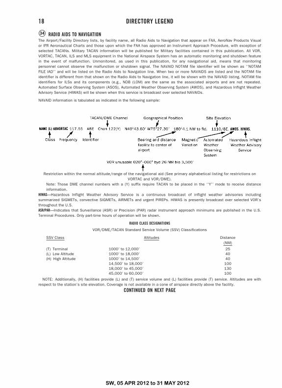
�34 RADIO AIDS TO NAVIGATIONThe Airport/Facility Directory lists, by facility name, all Radio Aids to Navigation that appear on FAA, AeroNav Products Visualor IFR Aeronautical Charts and those upon which the FAA has approved an Instrument Approach Procedure, with exception ofselected TACANs. Military TACAN information will be published for Military facilities contained in this publication. All VOR,VORTAC, TACAN, ILS and MLS equipment in the National Airspace System has an automatic monitoring and shutdown featurein the event of malfunction. Unmonitored, as used in this publication, for any navigational aid, means that monitoringpersonnel cannot observe the malfunction or shutdown signal. The NAVAID NOTAM file identifier will be shown as ‘‘NOTAMFILE IAD’’ and will be listed on the Radio Aids to Navigation line. When two or more NAVAIDS are listed and the NOTAM fileidentifier is different from that shown on the Radio Aids to Navigation line, it will be shown with the NAVAID listing. NOTAM fileidentifiers for ILSs and its components (e.g., NDB (LOM) are the same as the associated airports and are not repeated.Automated Surface Observing System (ASOS), Automated Weather Observing System (AWOS), and Hazardous Inflight WeatherAdvisory Service (HIWAS) will be shown when this service is broadcast over selected NAVAIDs.
NAVAID information is tabulated as indicated in the following sample:
Restriction within the normal altitude/range of the navigational aid (See primary alphabetical listing for restrictions onVORTAC and VOR/DME).
Note: Those DME channel numbers with a (Y) suffix require TACAN to be placed in the ‘‘Y’’ mode to receive distanceinformation.
HIWAS—Hazardous Inflight Weather Advisory Service is a continuous broadcast of inflight weather advisories includingsummarized SIGMETs, convective SIGMETs, AIRMETs and urgent PIREPs. HIWAS is presently broadcast over selected VOR’sthroughout the U.S.ASR/PAR—Indicates that Surveillance (ASR) or Precision (PAR) radar instrument approach minimums are published in the U.S.Terminal Procedures. Only part-time hours of operation will be shown.
RADIO CLASS DESIGNATIONS
VOR/DME/TACAN Standard Service Volume (SSV) Classifications
SSV Class Altitudes Distance(NM)
(T) Terminal 1000� to 12,000� 25(L) Low Altitude 1000� to 18,000� 40(H) High Altitude 1000� to 14,500� 40
14,500� to 18,000� 10018,000� to 45,000� 13045,000� to 60,000� 100
NOTE: Additionally, (H) facilities provide (L) and (T) service volume and (L) facilities provide (T) service. Altitudes are withrespect to the station’s site elevation. Coverage is not available in a cone of airspace directly above the facility.
CONTINUED ON NEXT PAGE
18 DIRECTORY LEGEND
SW, 05 APR 2012 to 31 MAY 2012
CONTINUED FROM PRECEDING PAGE
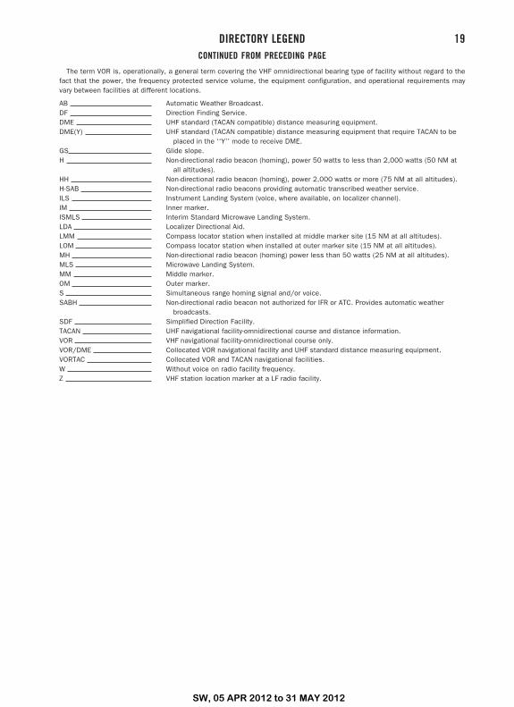
The term VOR is, operationally, a general term covering the VHF omnidirectional bearing type of facility without regard to thefact that the power, the frequency protected service volume, the equipment configuration, and operational requirements mayvary between facilities at different locations.
AB Automatic Weather Broadcast.DF Direction Finding Service.DME UHF standard (TACAN compatible) distance measuring equipment.DME(Y) UHF standard (TACAN compatible) distance measuring equipment that require TACAN to be
placed in the ‘‘Y’’ mode to receive DME.GS Glide slope.H Non-directional radio beacon (homing), power 50 watts to less than 2,000 watts (50 NM at
all altitudes).HH Non-directional radio beacon (homing), power 2,000 watts or more (75 NM at all altitudes).H-SAB Non-directional radio beacons providing automatic transcribed weather service.ILS Instrument Landing System (voice, where available, on localizer channel).IM Inner marker.ISMLS Interim Standard Microwave Landing System.LDA Localizer Directional Aid.LMM Compass locator station when installed at middle marker site (15 NM at all altitudes).LOM Compass locator station when installed at outer marker site (15 NM at all altitudes).MH Non-directional radio beacon (homing) power less than 50 watts (25 NM at all altitudes).MLS Microwave Landing System.MM Middle marker.OM Outer marker.S Simultaneous range homing signal and/or voice.SABH Non-directional radio beacon not authorized for IFR or ATC. Provides automatic weather
broadcasts.SDF Simplified Direction Facility.TACAN UHF navigational facility-omnidirectional course and distance information.VOR VHF navigational facility-omnidirectional course only.VOR/DME Collocated VOR navigational facility and UHF standard distance measuring equipment.VORTAC Collocated VOR and TACAN navigational facilities.W Without voice on radio facility frequency.Z VHF station location marker at a LF radio facility.
DIRECTORY LEGEND 19
SW, 05 APR 2012 to 31 MAY 2012
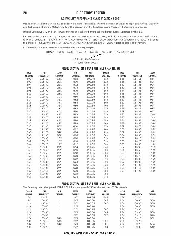
ILS FACILITY PEFORMANCE CLASSIFICATION CODES
Codes define the ability of an ILS to support autoland operations. The two portions of the code represent Official Categoryand farthest point along a Category I, II, or III approach that the Localizer meets Category III structure tolerances.
Official Category: I, II, or III; the lowest minima on published or unpublished procedures supported by the ILS.
Farthest point of satisfactory Category III Localizer performance for Category I, II, or III approaches: A – 4 NM prior torunway threshold, B – 3500 ft prior to runway threshold, C – glide angle dependent but generally 750–1000 ft prior tothreshold, T – runway threshold, D – 3000 ft after runway threshold, and E – 2000 ft prior to stop end of runway.
ILS information is tabulated as indicated in the following sample:
ILS/DME 108.5 I–ORL Chan 22 Rwy 18. Class IIE. LOM HERNY NDB.
ILS Facility PerformanceClassification Code
FREQUENCY PAIRING PLAN AND MLS CHANNELINGMLS
CHANNELVHF
FREQUENCYTACAN
CHANNEL500 108.10 18X502 108.30 20X504 108.50 22X506 108.70 24X508 108.90 26X510 109.10 28X512 109.30 30X514 109.50 32X516 109.70 34X518 109.90 36X520 110.10 38X522 110.30 40X524 110.50 42X526 110.70 44X528 110.90 46X530 111.10 48X532 111.30 50X534 111.50 52X536 111.70 54X538 111.90 56X540 108.05 17Y542 108.15 18Y544 108.25 19Y546 108.35 20Y548 108.45 21Y550 108.55 22Y552 108.65 23Y554 108.75 24Y556 108.85 25Y558 108.95 26Y560 109.05 27Y562 109.15 28Y564 109.25 29Y566 109.35 30Y
MLSCHANNEL
VHFFREQUENCY
TACANCHANNEL
568 109.45 31Y570 109.55 32Y572 109.65 33Y574 109.75 34Y576 109.85 35Y578 109.95 36Y580 110.05 37Y582 110.15 38Y584 110.25 39Y586 110.35 40Y588 110.45 41Y590 110.55 42Y592 110.65 43Y594 110.75 44Y596 110.85 45Y598 110.95 46Y600 111.05 47Y602 111.15 48Y604 111.25 49Y606 111.35 50Y608 111.45 51Y610 111.55 52Y612 111.65 53Y614 111.75 54Y616 111.85 55Y618 111.95 56Y620 113.35 80Y622 113.45 81Y624 113.55 82Y626 113.65 83Y628 113.75 84Y630 113.85 85Y632 113.95 86Y634 114.05 87Y
MLSCHANNEL
VHFFREQUENCY
TACANCHANNEL
636 114.15 88Y638 114.25 89Y640 114.35 90Y642 114.45 91Y644 114.55 92Y646 114.65 93Y648 114.75 94Y650 114.85 95Y652 114.95 96Y654 115.05 97Y656 115.15 98Y658 115.25 99Y660 115.35 100Y662 115.45 101Y664 115.55 102Y666 115.65 103Y668 115.75 104Y670 115.85 105Y672 115.95 106Y674 116.05 107Y676 116.15 108Y678 116.25 109Y680 116.35 110Y682 116.45 111Y684 116.55 112Y686 116.65 113Y688 116.75 114Y690 116.85 115Y692 116.95 116Y694 117.05 117Y696 117.15 118Y698 117.25 119Y
FREQUENCY PAIRING PLAN AND MLS CHANNELINGThe following is a list of paired VOR/ILS VHF frequencies with TACAN channels and MLS channels.
TACANCHANNEL
VHFFREQUENCY
MLSCHANNEL
2X 134.5 -2Y 134.55 -11X 135.4 -11Y 135.45 -12X 135.5 -12Y 135.55 -17X 108.00 -17Y 108.05 54018X 108.10 50018Y 108.15 54219X 108.20 -
TACANCHANNEL
VHFFREQUENCY
MLSCHANNEL
19Y 108.25 54420X 108.30 50220Y 108.35 54621X 108.40 -21Y 108.45 54822X 108.50 50422Y 108.55 55023X 108.60 -23Y 108.65 55224X 108.70 50624Y 108.75 554
TACANCHANNEL
VHFFREQUENCY
MLSCHANNEL
25X 108.80 -25Y 108.85 55626X 108.90 50826Y 108.95 55827X 109.00 -27Y 109.05 56028X 109.10 51028Y 109.15 56229X 109.20 -29Y 109.25 56430X 109.30 512
20 DIRECTORY LEGEND
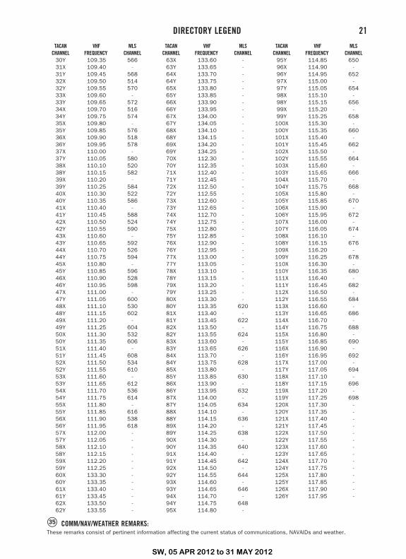
SW, 05 APR 2012 to 31 MAY 2012
TACANCHANNEL
VHFFREQUENCY
MLSCHANNEL
30Y 109.35 56631X 109.40 -31Y 109.45 56832X 109.50 51432Y 109.55 57033X 109.60 -33Y 109.65 57234X 109.70 51634Y 109.75 57435X 109.80 -35Y 109.85 57636X 109.90 51836Y 109.95 57837X 110.00 -37Y 110.05 58038X 110.10 52038Y 110.15 58239X 110.20 -39Y 110.25 58440X 110.30 52240Y 110.35 58641X 110.40 -41Y 110.45 58842X 110.50 52442Y 110.55 59043X 110.60 -43Y 110.65 59244X 110.70 52644Y 110.75 59445X 110.80 -45Y 110.85 59646X 110.90 52846Y 110.95 59847X 111.00 -47Y 111.05 60048X 111.10 53048Y 111.15 60249X 111.20 -49Y 111.25 60450X 111.30 53250Y 111.35 60651X 111.40 -51Y 111.45 60852X 111.50 53452Y 111.55 61053X 111.60 -53Y 111.65 61254X 111.70 53654Y 111.75 61455X 111.80 -55Y 111.85 61656X 111.90 53856Y 111.95 61857X 112.00 -57Y 112.05 -58X 112.10 -58Y 112.15 -59X 112.20 -59Y 112.25 -60X 133.30 -60Y 133.35 -61X 133.40 -61Y 133.45 -62X 133.50 -62Y 133.55 -
TACANCHANNEL
VHFFREQUENCY
MLSCHANNEL
63X 133.60 -63Y 133.65 -64X 133.70 -64Y 133.75 -65X 133.80 -65Y 133.85 -66X 133.90 -66Y 133.95 -67X 134.00 -67Y 134.05 -68X 134.10 -68Y 134.15 -69X 134.20 -69Y 134.25 -70X 112.30 -70Y 112.35 -71X 112.40 -71Y 112.45 -72X 112.50 -72Y 112.55 -73X 112.60 -73Y 112.65 -74X 112.70 -74Y 112.75 -75X 112.80 -75Y 112.85 -76X 112.90 -76Y 112.95 -77X 113.00 -77Y 113.05 -78X 113.10 -78Y 113.15 -79X 113.20 -79Y 113.25 -80X 113.30 -80Y 113.35 62081X 113.40 -81Y 113.45 62282X 113.50 -82Y 113.55 62483X 113.60 -83Y 113.65 62684X 113.70 -84Y 113.75 62885X 113.80 -85Y 113.85 63086X 113.90 -86Y 113.95 63287X 114.00 -87Y 114.05 63488X 114.10 -88Y 114.15 63689X 114.20 -89Y 114.25 63890X 114.30 -90Y 114.35 64091X 114.40 -91Y 114.45 64292X 114.50 -92Y 114.55 64493X 114.60 -93Y 114.65 64694X 114.70 -94Y 114.75 64895X 114.80 -
TACANCHANNEL
VHFFREQUENCY
MLSCHANNEL
95Y 114.85 65096X 114.90 -96Y 114.95 65297X 115.00 -97Y 115.05 65498X 115.10 -98Y 115.15 65699X 115.20 -99Y 115.25 658100X 115.30 -100Y 115.35 660101X 115.40 -101Y 115.45 662102X 115.50 -102Y 115.55 664103X 115.60 -103Y 115.65 666104X 115.70 -104Y 115.75 668105X 115.80 -105Y 115.85 670106X 115.90 -106Y 115.95 672107X 116.00 -107Y 116.05 674108X 116.10 -108Y 116.15 676109X 116.20 -109Y 116.25 678110X 116.30 -110Y 116.35 680111X 116.40 -111Y 116.45 682112X 116.50 -112Y 116.55 684113X 116.60 -113Y 116.65 686114X 116.70 -114Y 116.75 688115X 116.80 -115Y 116.85 690116X 116.90 -116Y 116.95 692117X 117.00 -117Y 117.05 694118X 117.10 -118Y 117.15 696119X 117.20 -119Y 117.25 698120X 117.30 -120Y 117.35 -121X 117.40 -121Y 117.45 -122X 117.50 -122Y 117.55 -123X 117.60 -123Y 117.65 -124X 117.70 -124Y 117.75 -125X 117.80 -125Y 117.85 -126X 117.90 -126Y 117.95 -
�35 COMM/NAV/WEATHER REMARKS:These remarks consist of pertinent information affecting the current status of communications, NAVAIDs and weather.
DIRECTORY LEGEND 21