Embed Size (px)
Citation preview
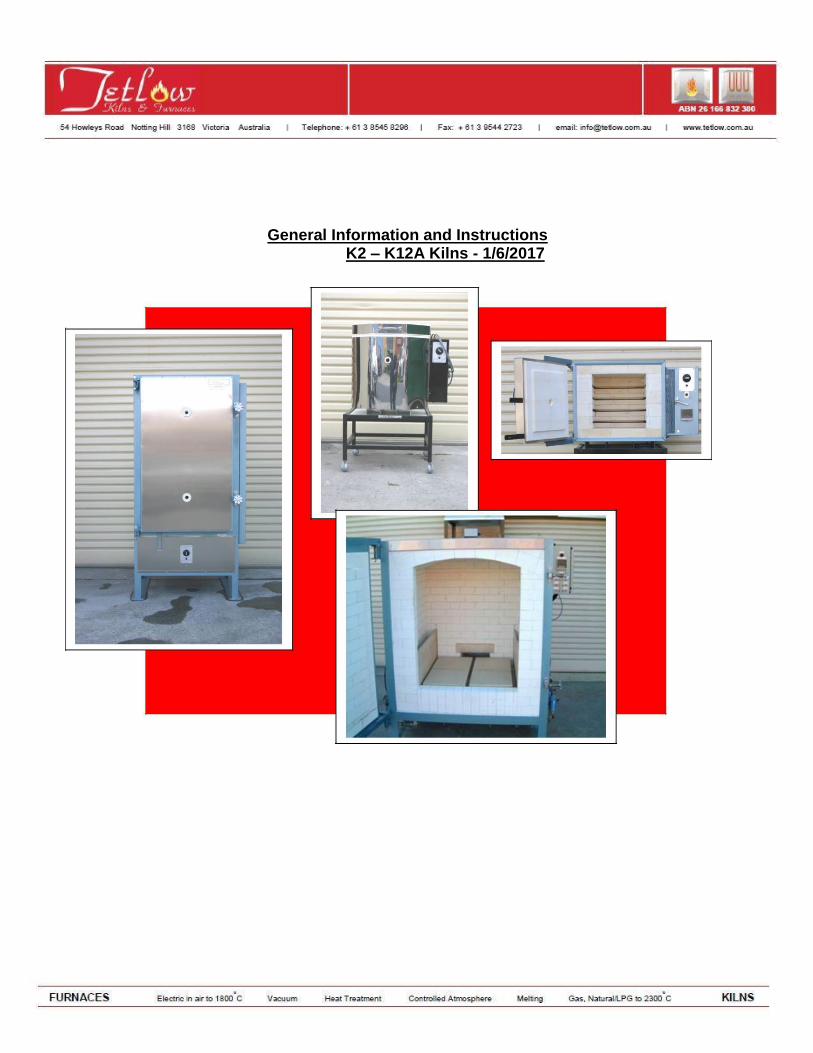
General Information and Instructions
K2 – K12A Kilns - 1/6/2017
KILN AND FURNITURE PACKING
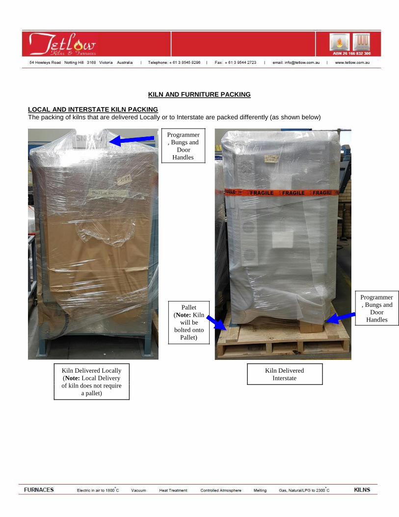
LOCAL AND INTERSTATE KILN PACKING The packing of kilns that are delivered Locally or to Interstate are packed differently (as shown below)
Programmer , Bungs and
Door Handles
Pallet (Note: Kiln
will be bolted onto
Pallet)
Kiln Delivered Locally Kiln Delivered
(Note: Local Delivery Interstate
of kiln does not require
a pallet)
Programmer , Bungs and
Door Handles
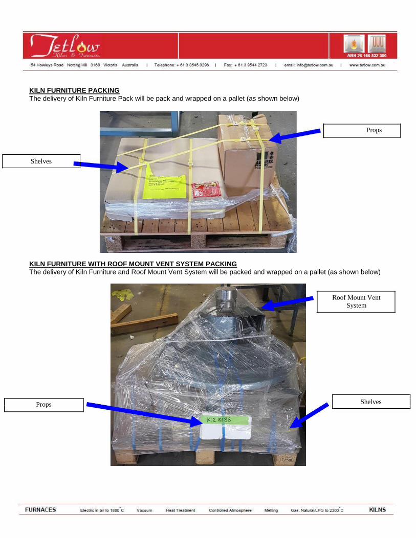
KILN FURNITURE PACKING The delivery of Kiln Furniture Pack will be pack and wrapped on a pallet (as shown below)
Props
Shelves
KILN FURNITURE WITH ROOF MOUNT VENT SYSTEM PACKING The delivery of Kiln Furniture and Roof Mount Vent System will be packed and wrapped on a pallet (as shown below)
Roof Mount Vent System
Shelves
Props
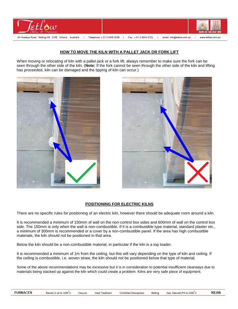
HOW TO MOVE THE KILN WITH A PALLET JACK OR FORK LIFT
When moving or relocating of kiln with a pallet jack or a fork lift, always remember to make sure the fork can be seen through the other side of the kiln. (Note: If the fork cannot be seen through the other side of the kiln and lifting has proceeded, kiln can be damaged and the tipping of kiln can occur.)
POSITIONING FOR ELECTRIC KILNS
There are no specific rules for positioning of an electric kiln, however there should be adequate room around a kiln.
It is recommended a minimum of 150mm of wall on the non-control box sides and 600mm of wall on the control box side. The 150mm is only when the wall is non-combustible. If it is a combustible type material, standard plaster etc., a minimum of 300mm is recommended or a cover by a non-combustible panel. If the area has high combustible materials, the kiln should not be positioned in that area.
Below the kiln should be a non-combustible material, in particular if the kiln is a top loader.
It is recommended a minimum of 1m from the ceiling, but this will vary depending on the type of kiln and ceiling. If the ceiling is combustible, i.e. woven straw, the kiln should not be positioned below that type of material.
Some of the above recommendations may be excessive but it is in consideration to potential insufficient clearways due to
materials being stacked up against the kiln which could create a problem. Kilns are very safe piece of equipment.
POSITIONING OF KILNS OUTSIDE
If the kiln is to be positioned outside of a building, it is important to put a structure around the kiln that will shield it from adverse weather conditions, such as heavy rain and very high humidity. If kilns are exposed to excessive moisture, the bricks will absorb the moisture, and when firing the kiln, the moisture will disperse from the brickwork causing future problems. It is a preferred option to have the kiln inside a structure, but still allowing adequate ventilation around the kiln.
POSITIONING OF KILNS IN A SCHOOL ROOM
It is recommended that the kiln has a barrier around the outside to stop inquisitive children from touching the kiln during operations.
VENTILATION OF ELECTRIC KILNS
It is recommended that kilns be fitted with a powered ventilation system, which can be provided by Tetlow. Adequate ventilation in the room must be allowed for the system to work effectively, i.e. air flow.
Tetlow Kilns and Furnaces can visit sites to recommend positioning and ventilation system of electric kilns. This would be charged at out standard rate including travel time, on-site time and preparation of report.
ELECTRICAL CONNECTION FOR KILNS
Please ensure that you do not install a kiln on an electrical connection with an EARTH LEAKAGE SYSTEM (RCD or
RESIDUAL CURRENT DEVISE BREAKER). These systems will often cause the kiln to trip out (as with stoves or ovens).
A simple circuit breaker is more suitable. Should an Electrician have an issue with not installing an RCD then the kiln
may need to be hardwired to the connection.
Small kilns up to 20amp, single phase come complete with 3-pin plug. All kilns above 20amp, single phase or multi-phase require direct wiring. All kilns require neutral.
All kilns require neutral. All active and neutral connections are to ceramic terminal blocks mounted in the control area along with a screwed terminal for earth. 1phase: 3wires 1active 1neutral 1earth
2phase: 4wires 2active 1neutral 1earth
3phase: 5wires 3active 1neutral 1earth
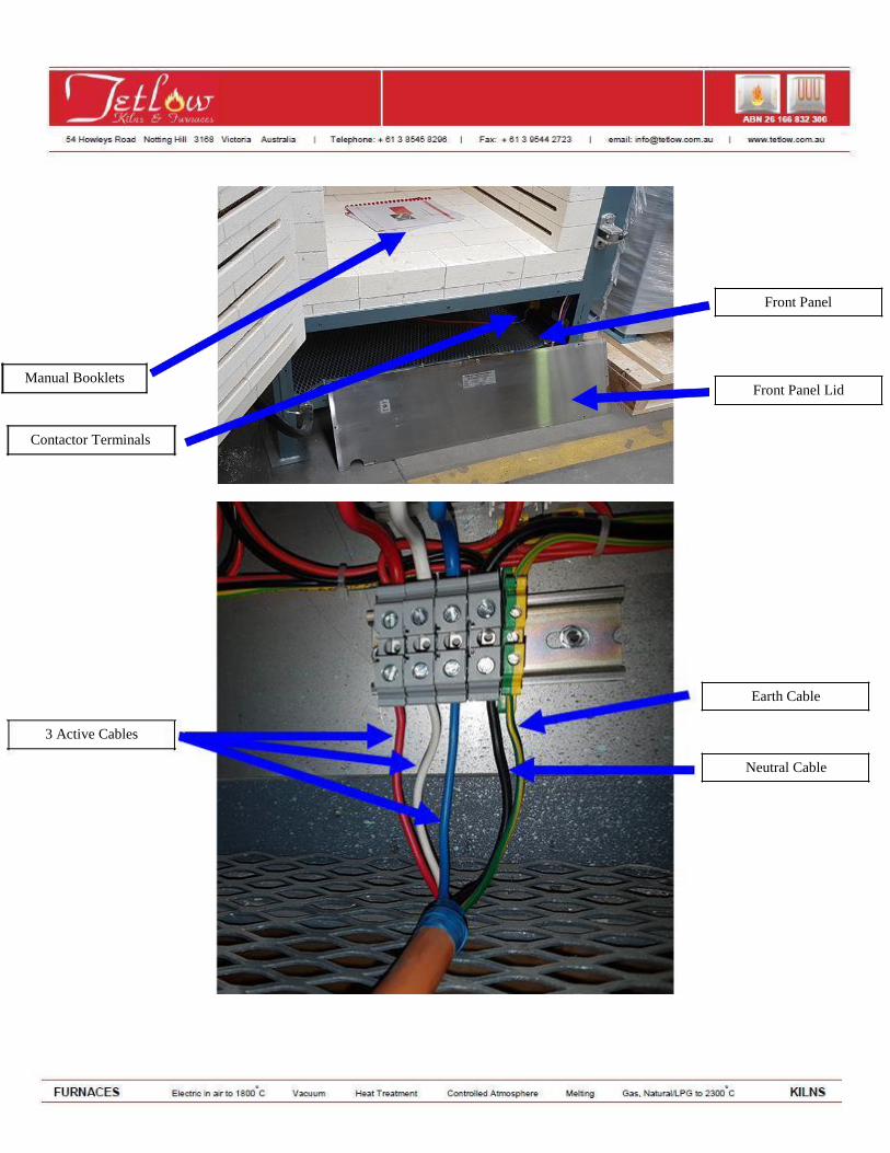
Manual Booklets Contactor Terminals
3 Active Cables
Front Panel
Front Panel Lid
Earth Cable
Neutral Cable
ELECTRICAL ISOLATORS
An electrical isolating switch should be fitted adjacent to the kiln, so the kiln can be isolated when not in use. It is recommended that circuit breakers or fuses and electrical cables are rated at a minimum of 20% above the required amperage of the unit. Important: Before electrical connections are made, check and secure all terminal screws and nuts on factory fitted cables (contactor, etc). These may have become loose in transport and associated handling.
FIRING OF ELECTRIC CRAFT KILN
BRICKS The bricks used for manufacturing of electrical kilns are of the refractory insulation type. These have all the heat-resisting qualities of refractory bricks but are very porous.
These allow for air, a good insulator, to use the huge number of air pockets inside these bricks, so that if one face of the brick is exposed to heat it takes a considerable time before this heat is transmitted through the brick to the opposite face. The pore structures also make the bricks very light in weight.
FITTING OF ELEMENTS
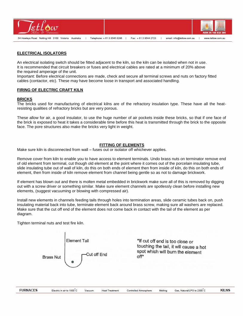
Make sure kiln is disconnected from wall – fuses out or isolator off whichever applies. Remove cover from kiln to enable you to have access to element terminals. Undo brass nuts on terminator remove end of old element from terminal, cut though old element at the point where it comes out of the porcelain insulating tube, slide insulating tube out of wall of kiln, do this on both ends of element then from inside of kiln, do this on both ends of element, then from inside of kiln remove element from channel being gentle so as not to damage brickwork. If element has blown out and there is molten metal embedded in brickwork make sure all of this is removed by digging out with a screw driver or something similar. Make sure element channels are spotlessly clean before installing new elements, (suggest vacuuming or blowing with compressed air). Install new elements in channels feeding tails through holes into termination areas, slide ceramic tubes back on, push insulating material back into tube, terminate element back around brass screw, making sure all washers are replaced. Make sure that the cut off end of the element does not come back in contact with the tail of the element as per diagram. Tighten terminal nuts and test fire kiln.
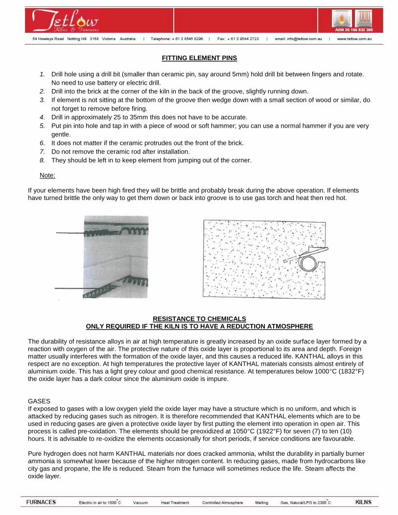
FITTING ELEMENT PINS
1. Drill hole using a drill bit (smaller than ceramic pin, say around 5mm) hold drill bit between fingers and rotate.
No need to use battery or electric drill.
2. Drill into the brick at the corner of the kiln in the back of the groove, slightly running down.
3. If element is not sitting at the bottom of the groove then wedge down with a small section of wood or similar, do
not forget to remove before firing.
4. Drill in approximately 25 to 35mm this does not have to be accurate.
5. Put pin into hole and tap in with a piece of wood or soft hammer; you can use a normal hammer if you are very
gentle.
6. It does not matter if the ceramic protrudes out the front of the brick.
7. Do not remove the ceramic rod after installation.
8. They should be left in to keep element from jumping out of the corner.
Note:
If your elements have been high fired they will be brittle and probably break during the above operation. If elements have turned brittle the only way to get them down or back into groove is to use gas torch and heat then red hot.
RESISTANCE TO CHEMICALS
ONLY REQUIRED IF THE KILN IS TO HAVE A REDUCTION ATMOSPHERE
The durability of resistance alloys in air at high temperature is greatly increased by an oxide surface layer formed by a reaction with oxygen of the air. The protective nature of this oxide layer is proportional to its area and depth. Foreign matter usually interferes with the formation of the oxide layer, and this causes a reduced life. KANTHAL alloys in this respect are no exception. At high temperatures the protective layer of KANTHAL materials consists almost entirely of aluminium oxide. This has a light grey colour and good chemical resistance. At temperatures below 1000°C (1832°F) the oxide layer has a dark colour since the aluminium oxide is impure. GASES If exposed to gases with a low oxygen yield the oxide layer may have a structure which is no uniform, and which is attacked by reducing gases such as nitrogen. It is therefore recommended that KANTHAL elements which are to be used in reducing gases are given a protective oxide layer by first putting the element into operation in open air. This process is called pre-oxidation. The elements should be preoxidized at 1050°C (1922°F) for seven (7) to ten (10) hours. It is advisable to re-oxidize the elements occasionally for short periods, if service conditions are favourable. Pure hydrogen does not harm KANTHAL materials nor does cracked ammonia, whilst the durability in partially burner ammonia is somewhat lower because of the higher nitrogen content. In reducing gases, made from hydrocarbons like city gas and propane, the life is reduced. Steam from the furnace will sometimes reduce the life. Steam affects the oxide layer.
In atmosphere with a sulphur content KANTHAL materials have a considerably better durability than nickel resistance materials. In oxidizing gases having a sulphur content, KANTHAL is especially durable. Reducing gases with a sulphur content reduce the life, and in such cases KANTHAL is the only possible resistance material. All halogens, such as chlorine or fluorine, are harmful. Definite figures for the life of KANTHAL elements working in such atmosphere cannot be given. KANTHAL A-1 and A have a better resistance than DS1 and DSD. At lower temperatures, however, the difference is insignificant.
First Firing of Elements
It is recommended that the first firing of a new furnace elements is a slow firing, with the furnace empty, to a temperature 10% - 15% less than the maximum temperature of the furnace, say 1050°C. Do not fit ceramic close of bungs to vent holes during dry out firing.
You should heat up to 1050°C with a ramp up time of seven (7) hours, (roughly 150°C per hour)
Hold at 1050°C for four (4)hours
Turn off the elements and allow to cool with the door closed until the furnace is below 200°C
The elements will now be oxidized and ready for use, and added benefit is this will enable the cement to mature/dry and to remove moisture from the brickwork. It is recommended that the electrical supply to your furnace be fitted with an isolating switch within close proximity of kiln so power can be turned off in case of emergency or when kiln needs servicing. i.e. switch not attached to kiln but in close proximity of furnace. It is further recommended that adequate ventilation be supplied to furnace by way of a Tetlow ventilation system. If this is not fitted the furnace should be in a well-ventilated position with exhaust fan to the atmosphere or similar. We would recommend that all close off bungs are left out during firing particularly if the product to be fired will give off by products that may contaminate the furnace.
KILN ACCESSORIES AND INSTRUMENTATION
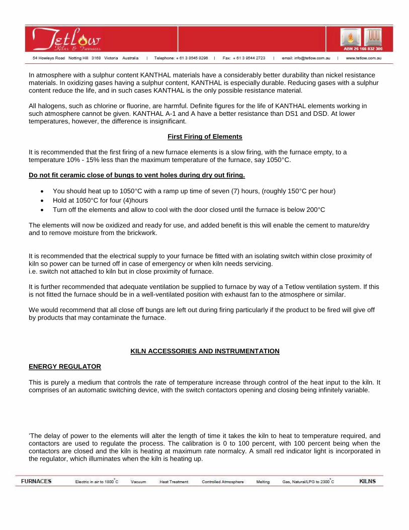
ENERGY REGULATOR
This is purely a medium that controls the rate of temperature increase through control of the heat input to the kiln. It comprises of an automatic switching device, with the switch contactors opening and closing being infinitely variable. ‘The delay of power to the elements will alter the length of time it takes the kiln to heat to temperature required, and contactors are used to regulate the process. The calibration is 0 to 100 percent, with 100 percent being when the contactors are closed and the kiln is heating at maximum rate normalcy. A small red indicator light is incorporated in the regulator, which illuminates when the kiln is heating up.
An energy regulator is a very useful piece of equipment to easily control the rate of temperature control. Thus, if thick-walled pots are being fired, the rate of temperature increase can very easily be reduced. If a pyrometer is fitted to the kiln and there is a need to maintain the kiln at a certain temperature, the energy regulator setting can be adjusted until a position is found where the elements would switch on and off at a rate slow enough to prevent further temperature rise, but fast enough to prevent the temperature dropping. This procedure should only be done for short periods of time to ensure minimal temperature drifts.
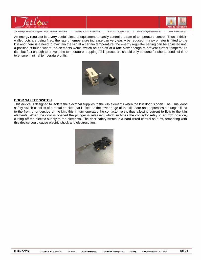
DOOR SAFETY SWITCH This device is designed to isolate the electrical supplies to the kiln elements when the kiln door is open. The usual door safety switch consists of a metal bracket that is fixed to the lower edge of the kiln door and depresses a plunger fitted to the front or underside of the kiln, this in turn operates the contactor relay, thus allowing current to flow to the kiln elements. When the door is opened the plunger is released, which switches the contactor relay to an “off” position, cutting off the electric supply to the elements. The door safety switch is a hard wired control shut off, tempering with this device could cause electric shock and electrocution.
PYROSCOPES AND TEMPERATURE CONTROL
Before the intensive study of pyrotetric practice the sense organs were the only means of determining temperatures and kiln firemen estimated the temperature of a kiln by reference to the degree and colour of the glow inside it. The determination of temperature by sight and feel, however, can only be an approximation and it is quite inadequate.
There are basically two methods of controlling a kiln firing: by the use of pyrometers and by the use of pyroscopes. Pyrometers and Pyroscopes are, however, often used in conjunction as they measure two completely different functions. Pyrometers measure temperature and pyroscopes measure heat work.
PYROSCOPES Pyroscopes are indicators made of ceramic mixtures based on silicates. The chemical nature of silicate mixtures is such that they do not have definite melting points, but they have a temperature range in which part of the mixture is melted and the remainder is solid. In this temperature range the process of glass formation (vitrification) takes place. When sufficient degree of vitrification occurs, the pyroscope can no longer support itself and bends or collapses, thus giving a visible indication. There are two ways of attaining this result. The first is to heat the pyroscope to a temperature high enough to produce this effect quickly and the second is to slightly lower the temperature but to hold this temperature for a longer time.
Since pyroscopes tend to be of a similar composition to pottery bodies, they offer a very good means of controlling the finishing point of a kiln firing. Pyroscope is like pottery and is correctly fired when the correct degree of vitrification has taken place. If a kiln firing is done slowly this will be reached at a lower temperature than when the firing is done very quickly, therefore the reliance on pyroscope alone to determine the finishing point of a kiln firing can be misleading.
CONES Cones are possibly the most important and useful way of controlling a kiln firing. They are commonly classified as pyroscopes; Buller rings and Holdcroft bars fall into the same category.
Staffordshire cones come generally in two sizes, standard cones are 2½ inches tall and miniature cones are 1inch tall. The cones are three-sided conical shape and made of a carefully controlled mixture of ceramic materials, which is designed to give a graduated scale of fusing temperatures at approximately 20°C intervals.
The cones, which melt at the lower temperature, contain a higher proportion of fluxes than those melting at the higher temperatures, which contain increasingly larger proportions of refractory oxides. This melting or fusing temperature is denoted by a number which is stamped into the back of the cone and by reference to the Staffordshire cone chart, which can obtain an approximate melting point for each of the different numbers. Although it is commonly assumed that the Staffordshire cones melt at indicated temperatures on the chart, the cones can also melt and collapse when they have been subjected to a certain temperature, or rate of temperature increase, for a certain length of time.
Time factor is important because it is usually assumed that when a kiln fires to 1000°C over a period of 8 to 10 hours, the ware has been fired to its recommended temperature and therefore fired correctly. However, if firing is controlled solely by a pyrometer, then the kiln would have switched off when the temperature reached 1000°C and the ware fired in 3 to 4 hours would not have been properly fired and would probably be underfired when withdrawn from the kiln. This is where the time factor of Staffordshire cone becomes useful.
Staffordshire cones will only collapse when subjected to heat for a certain length of time and will not collapse if they are fired too rapidly until a temperature is reached which is considerably higher that the indicated number stamped on the back. Similarly, if the cones are fired too slowly, they will probably collapse at a temperature earlier than that indicated by the cone number. In this way Staffordshire cones give an indication of the amount of heat work applied to the ware and not merely the temperature to which the ware is subjected.
It should also be noted that other factors can influence the temperature in which the Staffordshire cones collapse, such as usage in a strongly reducing atmosphere where chemical reactions may take place, causing the cone to withstand higher temperatures than usual. There are also other potential various affects that could cause misleading. Sulphur gases can also attack the Staffordshire cones, resulting in bloating and grey discolouration, which could distort collapsing temperatures.
It should be noted that other factors could influence the temperature at which Staffordshire cones collapse. If they are used in a strongly reducing atmosphere then it is possible for a chemical reaction to take place which results in a hard refractory skin being formed on the outside of the cone. The cone may then stand quite upright and the temperature of the kiln continue to increase considerably beyond the point at which the cone was supposed to have collapsed. It is even possible for this hard skin to be formed and yet for the inside of the cone to melt and run away, with the result that the refractory shell of the cone which may be still standing upright misleads the operator. Sulphur gases can also attack Staffordshire cones, resulting in bloating and a grey discolouration which, again, tends to distort the collapsing temperature.
One of the most important considerations in the use of pyroscopes is the way in which they are mounted. This is generally done by inserting the base of the cones either into special cone holders or into a pad of plastic clay, but regardless of the type of mounting it is important that all the cones be embedded to the same depth. It is necessary for
the cones to be placed at an angle of about 15 to the vertical, and to ensure that the manufacturer slants the base of the cone so that this inclination is automatically brought about when the cone is stood upright.
It is standard to use a series of three cones for each firing, one cone indicating a temperature of about 20C below the temperature to which the ware is to be fired, one cone indicating the required temperature and one cone indicating a
temperature 20C above the required one. In this way the collapse of the lower cone serves as a warning that the temperature is rising to the point at which the second cone will collapse (at which time the kiln should be switched off). The third cone serves as a guard to show potential overfiring.
It is important to place the cones in some definite order, which is usually done by placing the cones from left to right in order of increasing fusion point so that the cone on the extreme right will be the last to go down. The correct firing of any cone will be indicated when the cone bends over so that its tip bends down and touches the base on which the cone is mounted. This is referred to as the end-point of the cone. If the temperature continues to increase the cone will collapse further and eventually melt completely.
TEMPERATURE MEASURING INSTRUMENTS (PYROMETERS) There are different types of temperature-measuring instruments, but the ones generally used consists of a thermocouple attached by compensating cables to an instrument, which transforms the voltage fed into it from the thermocouple into degrees of temperature indicated on a scale. The standard pyrometer generally has a simple galvanometer as the recording instrument whereas the more sophisticated recording instruments generally have potentiometric systems or a combination of the two.
POTENTIONMETERS The word “potentiometric” occurs frequently in temperature measurement systems and describes merely the system used inside the recording instrument to measure accurately and to convert into degrees of temperature the very small voltages fed into it from the thermocouple.
Important “Do’s” and “Don’ts” when installing pyrometers DON’T connect electric mains supply to pyrometer/thermocouple terminals. DON’T run the compensating cables near or parallel to electric mains as otherwise the compensating cables will
have an electric current induced in them from the main cables, which will result in inaccurate readings on the instrument.
DON’T use ordinary copper cable for connecting the thermocouple to the pyrometer, as this will not compensate for temperature changes.
DON’T shorten or lengthen the cable or thermocouple as the pyrometer has been calibrated for external resistance.
OTHER IMPORTANT POINTS: The temperature inside the kiln is indicated on the pyrometer dial at all times.DON’T adjust the instrument to read zero if the kiln is at room temperature.
THE STANDARD PYROMETER This consists of a galvanometer fitted with a temperature scale, a thermocouple housed inside a porcelain sheath, and two pieces of compensating cable for connecting the two.
Installation is simple – the metal framework of the kiln is drilled by the manufacturer at a position suitable for the installation of a thermocouple. All that is necessary is to push the thermocouple into the hole provided in the kiln wall and keep the cold junction about 1inch away from the kiln wall. Place pyrometer in suitable position and a screw fitted to the front or just underneath the front of the instrument can be adjusted to set the instrument reading to the room
temperature, i.e. normally about 18C. THERMOCOUPLES Thermocouples are the “working end” of the pyrometer that projects inside the kiln and generates the current, which is measured by the instrument fixed outside the kiln.
If two different metals are drawn into wires and they are joined together at one end, a small electric current is generated when this joint of the two wires is heated. The greater the amount of heat applied to the junction, the greater will be the voltage generated in the wires. By measuring this voltage one can therefore get some indication of the amount of heat being applied to the junction of the wires.
Chromel-Alumel Chromel (a nickel chromium alloy) for one wire. Alumel (an alloy of nickel, aluminium, manganese and silicon) for the
other. Used for temperatures up to 2000F (1150C).
Platinum – 10 percent Rhodium An alloy of 10 percent rhodium and 87 percent of platinum for one wire and pure platinum for the other. Used for
temperatures up to 2700F (1480C).
Platinum is a very expensive metal, and for this reason, the thermocouples based on platinum are very much more expensive than the Chromel-Alumel types.
The cold end of the thermocouple is generally referred to as the “cold junction”, the end of the thermocouple projecting into the firing chamber being referred to as the “hot junction”.
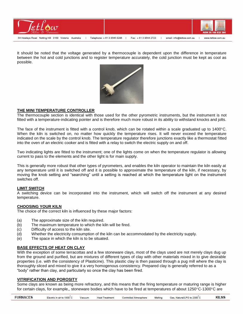
It should be noted that the voltage generated by a thermocouple is dependent upon the difference in temperature between the hot and cold junctions and to register temperature accurately, the cold junction must be kept as cool as possible. THE MINI TEMPERATURE CONTROLLER The thermocouple section is identical with those used for the other pyrometric instruments, but the instrument is not fitted with a temperature-indicating pointer and is therefore much more robust in its ability to withstand knocks and jolts.
The face of the instrument is fitted with a control knob, which can be rotated within a scale graduated up to 1400C. When the kiln is switched on, no matter how quickly the temperature rises. It will never exceed the temperature indicated on the scale by the control knob. The temperature regulator therefore junctions exactly like a thermostat f itted into the oven of an electric cooker and is fitted with a relay to switch the electric supply on and off.
Two indicating lights are fitted to the instrument; one of the lights come on when the temperature regulator is allowing current to pass to the elements and the other light is for main supply.
This is generally more robust that other types of pyrometers, and enables the kiln operator to maintain the kiln easily at any temperature until it is switched off and it is possible to approximate the temperature of the kiln, if necessary, by moving the knob setting and “searching” until a setting is reached at which the temperature light on the instrument switches off.
LIMIT SWITCH A switching device can be incorporated into the instrument, which will switch off the instrument at any desired temperature.
CHOOSING YOUR KILN The choice of the correct kiln is influenced by these major factors:
(a) The approximate size of the kiln required. (b) The maximum temperature to which the kiln will be fired. (c) Difficulty of access to the kiln site. (d) Whether the electricity consumption of the kiln can be accommodated by the electricity supply. (e) The space in which the kiln is to be situated.
BASE EFFECTS OF HEAT ON CLAY With the exception of some terracottas and a few stoneware clays, most of the clays used are not merely clays dug up from the ground and purified, but are mixtures of different types of clay with other materials mixed in to give desirable properties (i.e. with the consistency of Plasticine). This plastic clay is then passed through a pug mill where the clay is thoroughly sliced and mixed to give it a very homogenous consistency. Prepared clay is generally referred to as a “body” rather than clay, and particularly so once the clay has been fired.
VITRIFICATION AND POROSITY Some clays are known as being more refractory, and this means that the firing temperature or maturing range is higher
for certain clays, for example,, stoneware bodies which have to be fired at temperatures of about 1250C-1300C are
more refractory than earthenware one which fire at 1100C-1150C. Vitrification and porosity are terms used to describe the degree of water retention of the body after firing. A vitrified body is one that is dense and nonporous or low in porosity. The porosity of a body generally decreases as it is fired to a high temperature.
A body is correctly fired when it has been fired to its maximum degree of vitrification without deforming or has been fired to a temperature which has enabled the body to develop a sufficient coefficient of contraction to enable glazes to be used without crazing. The range of temperatures at which this stage is reached varies from one type of body to another and is referred to as the firing range, maturing range, or vitrification point of the clay. Some clay, i.e. stoneware, will be almost completely vitrified when this point has been reached; others will possess an appreciable degree of porosity – such as the earthenware and terracotta types.
The golden rule of pottery is that it should always be dry before firing. If damp pottery is placed in the kiln, there is a great risk of cracking or explosion during the firing operation, with bits being scattered over all adjacent pottery pieces causing damage. A good way of determining whether clayware is dry is to place it against the cheek and if it feels cold then the ware is damp and must be dried further. Thick pieces of pottery take longer to dry and longer to fire than thin pieces. If you place thick and thin pieces of pottery into the same kiln, the kiln should be fired more slowly compared to only firing thin pieces.
When clay is fired, it undergoes several complex changes, therefore even if it is dry when placed into the kiln, a considerable amount of water vapor is still driven off during the firing operation. This volume of water driven off may be about fifty times the volume of the kiln and is not water that can be dried, and they shrink still further during the firing operation. This degree of shrinkage varies with clay and is generally higher in those bodies which have the firing temperatures. The more clay is present in the body, the greater the degree of shrinkage.
THE IMPORTANCE OF SILICA Silica is sometimes regarded as the basis of pottery industry because it is the most important material used in ceramics and the most important characteristic of silica is its behavior when heated. Silica can be located in many different materials and the silica crystal has several different forms and modifications. When silica is heated, some of it changes from one form to another only to revert to the original form when subsequently cooled. Other modifications of silica can change permanently to another form which remains even after cooling.
MODIFICATIONS OF SILICA The most important crystal modifications of silica are as follows:
(alpha) quartz (beta) quartz
(alpha) tridymite (beta) tridymite (alpha) cristobalite (beta) cristobalite
Alpha and beta quartz, and alpha and beta cristobalite modifications are similar and should be cautioned. When these silica are under the influence of heat, it expands and when it is subsequently cooled, beta quartz reverts to its original form of alpha quartz causing a contraction of the silica mass.
When silica is heated, it gradually expands until a temperature of approximately 225C is reached and then it will expand considerably as the alpha cristobalite content changes to beta cristobalite, which is the same chemical composition but a larger volume. As heating is continued, another sudden expansion occurs at a temperature of
approximately 550 - 575C, when alpha quartz changes to beta quartz.
As heating continues, other forms of silica begin to change into beta cristobalite. This conversion progresses with
increasing rapidity as the temperature is raised higher. If silica is heated above 1200C for example, most of it is converted into beta cristobalite, thus the higher the temperature to which a pottery clay or body is fired, the more cristobalite is developed.
As silica is cooled, it gradually contracts until a temperature of approximately 575 - 550C is reached, at which point the beta quartz content reverts to its original alpha quartz form accompanied by a sudden contraction. As the silica is cooled still further, the point at which beta cristobalite changes back to alpha cristobalite is reached when the
temperature drops to approximately 225C. This beta to alpha cristobalite change causes another sudden volume contraction.
These sudden expansions and contractions at the certain temperatures occur every time the silica, or a body containing silica, is fired. Therefore, this occurs during glost firings as well as biscuit firings, and if heating or cooling of the pottery is proceeding too quickly, the stresses set up by the above silica “inversions” can, and often do, result in cracks right through the pottery causing the fault known as “dunting”.
The formation of an appreciable amount of cristobalite renders pottery clays and bodies craze-proof. This is because the beta to alpha cristobalite changes as the glost-fired ware is being cooled suddenly shrinks the biscuit ware, causing the glaze covering it to be placed in a state of compression.
STAGES IN BISCUIT FIRING
1. Water Smoking This covers the period from the beginning of the firing up to a temperature of about 150C. During this period any remaining mechanically held water present in the clay is boiled away. Removal occurs in two ways: firstly, the body continues to contract until each particle touches its neighbor and secondly, water is removed from between the particles.
2. Dehydration Period This covers an approximate temperature range of 150C to 600C. The chemically combined water present in the clay
mostly leaves the body between a range of 200C - 460C up to 600C but traces are still present up to 900C. During this period of time the amount of steam given off from the ware will be about fifty times the interior volume of the kiln and this must be allowed to escape easily from the kiln. If the kiln is heated too quickly from the commencement of firing up to the end of the dehydration period, the steam formed inside the body may not be able to get to the surface quickly enough and may build up to such a pressure that the pottery is blown apart. Firing should therefore be at a fairly slow rate over this temperature range.
Incidentally, by 800C the clay is as porous as a sponge, as at this temperature it has lost all chemically held water and most of the carbon and had has had no readjustment to the other ingredients. At this stage, the body is lighter in weight and extremely porous compared to when it was first placed in the kiln. If the biscuit is too porous, it has not been fired enough and if it is too vitreous then it has been over fired.
3. Vitrification Period This period has a temperature range from approximately 900C to the firing temperature of the clay. The fluxes present in the body begin to react with the clays and tend to soften and melt as the temperature increases. If the temperature is taken beyond the vitrification point of the body, gases would be given off and lead to bloating or blistering. At this point, the fluxes of the body are literally boiling.
BASIC EFFECTS OF HEAT ON GLAZES Glazes are suspended in water or materials which will subsequently melt together to form a glasslike material.
MATCHING OF GLAZES Glazes have to be “matched” to the body to which they are applied if good craze-resistance is to be obtained. This means that the rate of expansion and contraction of the glaze must be similar to that of the body otherwise one will crack away from the other if the fired pot is suddenly heated or cooled.
The rate of expansion of a glaze is dependent on the quantity and rate of expansion of each material used in its composition. Various materials have different rates and careful selection process should be used to design a glaze with specified rate of expansion and contraction. When the rate of expansion of the body is known, a matching glaze can be calculated and designed to suit it, thus “matching” to the body. The glaze is designed to have a slightly lower coefficient of expansion to the body so that during the cooling process, the glaze contracts slightly less than the body, which allows for slight compression of the glaze from the body, giving a built-in resistance against crazing.
STRESSES AND STRESS RELEASE When glaze is molten, some of its components are being vaporized and therefore any unnecessary continuance would make the glossy glaze dull and lack shine. As the glaze cools to the point at which it becomes a solid mass, the rate of vaporization decreases considerably. To obtain a good glossy glaze, the kiln should be cooled fairly quickly down to
approximately 750C, where most glazes become rigid. Any stresses or strains created in the glaze by this rapid rate of cooling can be easily absorbed because the molten glaze will allow the stresses to flow away. However, as the glaze becomes increasingly more rigid, caution must be applied as it is now able to crack and will do so if the stresses
and strains are caused by cooling too quickly. It is therefore best to fix an arbitrary point of 750C and to cool as quickly as possible down to this followed by a slower rate of cooling.
EFFECT OF COOLING Devitrification can also be caused if the glaze is cooled too slowly while it is molten. This will result in a transparent glaze with a milky appearance, and although there are other causes to this, slow cooling is the most common.
Once the temperature has fallen below 700C, there are two particularly dangerous temperatures, which is
approximately 575C and 225C. At these points, the silica in the body undergoes a sudden contraction during its cooling, which results in the body and the fixed glaze layer suddenly contracting. If all of the body and the glaze covering reach these temperature points at the same time, no problem will occur.
However as the above is rarely the case, due to difference of temperature points in different parts of the same pot by
10C-30C, cracking often occurs. This can be prevented by allowing the pot to absorb these stresses over as long a period of time as possible, which can only be done by cooling slowly when the temperature of the kiln approaches
575C and again when temperature reaches 225C. KILN PLACING Each shelf should be supported at three points rather than four points to prevent rocking from occurring. The supports should be arranged in a similar position for each succeeding shelf so that the total weight of the complete set of kiln furniture acts downwards through continuous columns.
The ideal material for putting on the shelves for glost firing purposes is a mixture of alumina and china clay or zircon and china clay mixed with water and painted on the shelves in the form of a wash so that it adheres quite firmly. Many companies sell a specially prepared mixture known as bat wash.
Kiln shelves and props are usually made from sillimanite or a mixture of refractory materials similar to sillimanite. These materials are very refractory and will easily withstand stoneware temperatures, however if the kiln bats are required to
withstand temperatures up to 1300C without warping, then it is best to select bats either ¾ or 1 inch thick. ½ inch thick
kiln shelves are very popular, but these are best reserved for temperatures below 1200C. BISCUIT KILN PLACING Kiln placing for a biscuit fire is simpler than placement for a glost fire, because the only aim is to get as many pots as possible into the smallest possible space.
Large heavy pieces may need a shrinkage platform under them to prevent warpage. These are smooth slabs of clay made from the same clay as the pot and therefore will shrink to the same extent. A thin layer of bat wash or silica sand
should be placed between the shrinkage platform and the shelf to enable the clay platform to shrink easily without sticking to the shelf.
The cones should be placed in a position and checked to ensure that they are in a position directly in line with the spy-hole in the kiln door.
GLOST KILN PLACING Care must be ensured in glost firing as the glaze covering the pots will stick them together if allowed to touch. Similarly, should any glaze adhere to the underside of a pot, it will stick the pot firmly to the kiln shelf. Therefore, the glaze is always removed from the base of the pot beforehand by using a sponge. If the removal of the glaze from the underside of a pot is difficult or time-consuming, stilts can be used as reassurance to no sticking. Repetitive usage of the stilts may cause the sharp edges to become blunt after several fires, and should be replaced with a new stilt, which will be less likely to leave a blemish on the base of the pot even when it is covered with a thin layer of glaze.
Stilts are particularly useful in the firing of glazed earthenware and terracotta wares to support the pots clear of the kiln shelf. Further advantage of using a stilt is that the air circulation under the pots helps to reduce the temperature variation between the top and bottom of the pottery article. However, usage of stilts can raise problems when firing stoneware. This is because if these wares are fired to full maturing temperature, the pots may begin to sag or squat over the stilts or any other supporting medium being used. Therefore when firing stoneware, the base is left unglazed and stood directly on the kiln shelf.
When placing for either biscuit or glost firing, leave a gap of at least 1-inch between the pot and the nearest element. Failure to do this may result in one side of the pot being scorched.
It is best to avoid placing differently colored glazed pots in the same firing. This is because the volatilization of glaze from one pot fan influences the color of its neighbor to a very noticeable degree. If this cannot be avoided, try to keep white and highly pigmented glazes, such as black, as distant from each other as possible.
FIRING Firstly, the vent plug should be removed to allow steam to escape more easily and the spy-hole left open, and if there is an energy regulator, this should be set at a fairly low setting. Switch the kiln to its low setting for 1hour to drive away any surplus of moisture retained from previous firing.
The objective of this procedure is to ensure that during the early stages of firing, the water vapor chemically held inside the clay that converts to steam, is allowed to escape from the kiln easily. The rate of temperature increase should be
fairly slow and no greater than 100C per hour for the thinner pieces of pottery. The thicker pieces will demand a
temperature increase that is considerably slower and as low as 50C-70C per hour.
When the kiln is set to its medium setting of about 50 to 70 on the energy regulator, leave this setting for 1hour or so before switching to the highest setting. The vent plug should be in position during this period and remain until the kiln is switched off.
As the kiln is gradually increasing in temperature, large amounts of steam, which may not be visible to the human eye, may be escaping from the vent hole and spy hole of the kiln. After approximately 2-4 hours, the energy regulator can be turned up to a reading of approximately “60” on the scale, and at this point the temperature should be in the region
of 150C – 350C.
The actual brickwork that lines the interior of the kiln will begin glowing red at a temperature of approximately 600C
and at 650C - 700C, the glowing will be very noticeable. At this point, the vents can be closed and the kiln will probably have been on medium setting for approximately 1-3 hours and can now be switched to the high setting to finish off the firing for the terracotta and earthenware types of clay. For stoneware clays, it is normally best to allow the
kiln to remain for an additional hour or so at its medium setting before switching to its high setting, since these clays contain comparatively higher amount of carbon.
Once the energy regulator is switched to 100%, the kiln will begin to increase temperature at its maximum speed. If this rate of temperature increase is too rapid, then switch the energy regulator to 90% or less.
The kiln interior will now glow brightly and after a further 2-3 hours, the temperature should be in the region of 800C - 1000C. If a pyrometer is fitted, then it will be easier to determine the point at which the kiln can be checked to see the Staffordshire cones. This procedure should normally begin when the reading on the pyrometer gives an indication of
30C or so before the collapse of the 1st
cone. If a pyrometer is not fitted, rely on glancing into the kiln through the spy
hole every 30minutes or so until the collapse of the 1st
cone. Once this occurs, look into the kiln every 10minutes and switch the kiln off the moment the cone to which the ware is being fired to has collapsed.
As the kiln temperature approaches the required glaze firing temperature, gas bubbles will still be escaping through the glaze layer and form craters in the glaze, and if firing has progressed very rapidly up to this stage, then there may not be sufficient time for these craters to disappear before kiln is switched off. The best option is to slowdown the rate of
temperature increase over the last 50C - 100C or so of the kiln firing if the kiln has been fired at a faster rate of about
100C per hour, and to observe results when kiln has cooled. If the glaze surface is pin-holed or has an “eggshell” or “orange peel” effect, or contains a large number of bubbles, then reduce the rate of temperature increase during the latter stages or heat soak the kiln for 30minutes before switching off, which can be done by turning down the setting of the energy regulator. Do not remove the vent plug to slowdown the rate of temperature increase as this will result in a wide temperature variation within the kiln.
Cooling Down Once firing is complete, the kiln should be switched off. The rate of kiln cooling varies with different models and depends on the temperature and amount of ware and shelves inside the kiln. It is best to leave the kiln as it is until the
interior temperature drops to approximately 100C - 150C, before opening the door.
The rate of cooling should vary to conform to the type of ware being fired. Many kilns cool too slowly to allow for the best results to be obtained from a glossy glaze, therefore to speed up cooling cycle in this case, partial or complete
removal of the vent plug can be done but should be replaced when the kiln has been dropped to 750C. Below this
temperature, the kiln should be allowed to cool slowly until approximately 130C. the cooling rate can be sped up after this by removing the vent plug or progressively opening the kiln door, noting that the door should be open in intervals and not be flung open as the cold air entering the kiln may crack the pots or kiln shelves.
Inspection Once the pots have been removed from the kiln, examine closely for discoloration or flaws. If there is a greyish color, there is usually some organic matter left inside, which means in future biscuit firings, the temperature increase should be delayed, leaving the kiln at medium setting for a longer period of time. If the pots are extensively cracked, a possible reason could be the steam pressure within the pot, and therefore in future, the kiln must be allowed to remain at its low setting for a longer period of time. Clay cracking can however also be caused by a very short, i.e. not very plastic, clay or by working with clay in too dry a condition, by not drying the pots evenly or by drying them too quickly. In such cases, these cracks would be present before being placed in the kiln though invisible to the unaided eye, but the biscuit firing should open them up.
If time is an issue, it is permissible to leave most kilns at its low setting overnight, as the kiln temperature will not rise
above 400C - 500C at this setting. The following morning, the kiln can be switched directly to its medium or high setting.
BISCUIT FIRING Earthenware and terracotta clays varies in firing temperatures with different types of these clays. Most earthenware
type clay has a firing range of 1100C - 1150C, but terracotta types vary more widely. During the period of time when pottery is fired, the complicated chemical reactions need to be taken place unhindered. There are two phases for these reactions: the first phase is being the formation of steam and the second phase being the burning away of all the organic materials.
This is with the assumption that the pots being fired are no thicker than ½ inch, which should cover 90 percent of the pottery produced by school and studio potters. If the pottery is thicker than this, then the rate of temperature increase of the kiln must be slower in order to allow the heat generated inside the kiln really to soak into the ware.
GLOST FIRING The temperature which the ware should be fired is the firing temperature recommended for the particular glaze being used, and the glost firing should always be taken to this recommended temperature.
SAFETY MEASURES
Kilns should be placed on fireproof base, i.e. concrete slab, and a 3inch or 4inch air space should be left around the kiln to prevent surface temperature of the kiln rising.
No objects should be placed on the kiln or leaned against the kiln as this will increase surface temperature of the kiln and create a fire hazard.
Rubbish should not be allowed to build around the base of the kiln as this will prevent air circulation under the kiln and create a fire hazard.
SERVICING
Tetlow Kilns and Furnaces recommends that you have your kiln serviced yearly by a suitably qualified person to ensure that you get the best possible results from your kiln.
For further information, locate us at our website, www.tetlow.com.au Do not hesitate to contact us at Tetlow Kilns and Furnaces at 03 8545 8296 or [email protected]
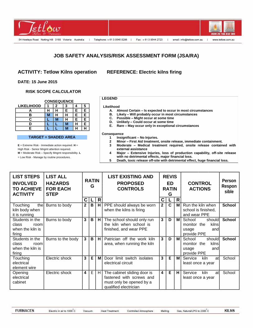
JOB SAFETY ANALYSIS/RISK ASSESSMENT FORM (JSA/RA)
ACTIVITY: Tetlow Kilns operation REFERENCE: Electric kilns firing
DATE: 15 June 2015
RISK SCOPE CALCULATOR
CONSEQUENCE
LIKELIHOOD 1 2 3 4 5 A H H E E E B M H H E E C L M H E E D L L M H E E L L M H H
TARGET = SHADED AREA
E = Extreme Risk - Immediate action required. H =
High Risk - Senior Mngmt attention required. M = Moderate Risk – Specify Mngmt responsibility. L
= Low Risk - Manage by routine procedures.
LEGEND Likelihood
A. Almost Certain – Is expected to occur in most circumstances B. Likely – Will probably occur in most circumstances C. Possible – Might occur at some time D. Unlikely – Could occur at some time E. Rare – May occur only in exceptional circumstances
Consequence
1 Insignificant – No Injuries. 2 Minor – First Aid treatment, onsite release, immediate containment. 3 Moderate – Medical treatment required, onsite release contained with
external assistance 4 Major – Extensive Injuries, loss of production capability, off-site release
with no detrimental effects, major financial loss. 5 Death, toxic release off-site with detrimental effect, huge financial loss.
LIST STEPS LIST ALL RATIN
LIST EXISTING AND REVIS Person
INVOLVED HAZARDS PROPOSED
ED
CONTROL
G Respon
TO ACHIEVE FOR EACH CONTROLS RATIN ACTIONS
sible
ACTIVITY STEP G
C L R C L R
Touching the Burns to body 2 B H PPE should always be worn 2 C M Run the kiln when School
kiln body when when the kilns is firing school is finished,
it is running and wear PPE
Students in the Burns to body 3 B H The school should only run 3 D M School should School
class room the kiln when school is monitor the kilns
when the kiln is finished, and wear PPE usage and
firing provide PPE
Students in the Burns to the body 3 B H Patrician off the work kiln 3 D M School should School
class room area, when running the kiln monitor the kilns
when the kiln is usage and
firing provide PPE
Touching Electric shock 3 E M Door limit switch isolates 3 E M Service kiln at School
electrical electrical circuit least once a year
element wire
Opening Electric shock 4 E H The cabinet sliding door is 4 E H Service kiln at School
electrical fastened with screws and least once a year
cabinet must only be opened by a
qualified electrician
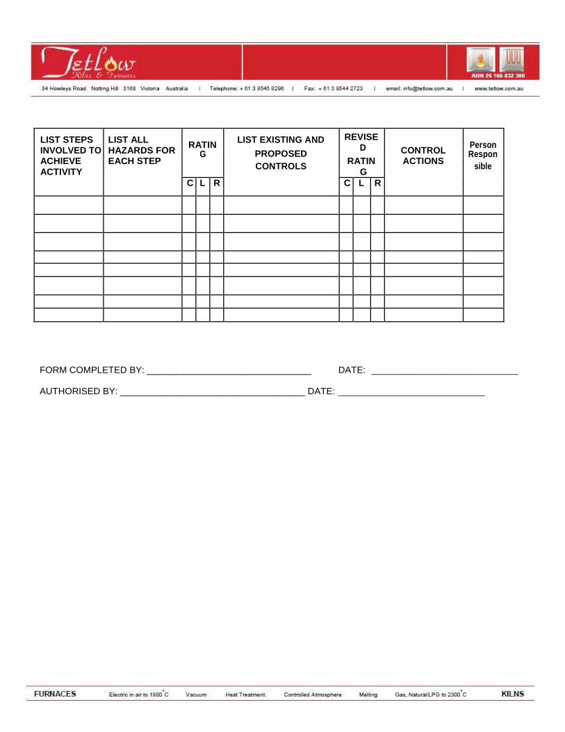
LIST STEPS LIST ALL RATIN
LIST EXISTING AND REVISE Person
D
INVOLVED TO HAZARDS FOR PROPOSED
CONTROL
G
Respon
ACHIEVE EACH STEP
RATIN ACTIONS
CONTROLS sible
ACTIVITY
G
C L R C L R
FORM COMPLETED BY: ________________________________ DATE: ______________________________
AUTHORISED BY: ____________________________________ DATE: ______________________________