Embed Size (px)
Citation preview
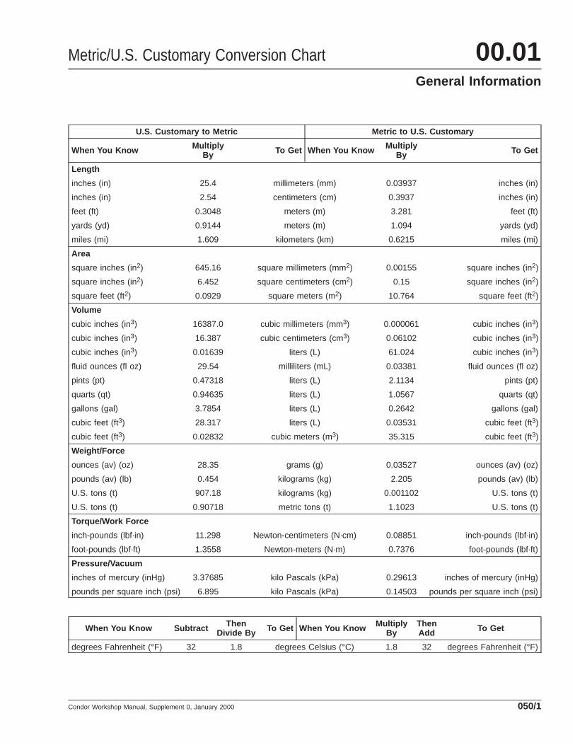
U.S. Customary to Metric Metric to U.S. Customary
When You Know MultiplyBy To Get When You Know Multiply
By To Get
Length
inches (in) 25.4 millimeters (mm) 0.03937 inches (in)
inches (in) 2.54 centimeters (cm) 0.3937 inches (in)
feet (ft) 0.3048 meters (m) 3.281 feet (ft)
yards (yd) 0.9144 meters (m) 1.094 yards (yd)
miles (mi) 1.609 kilometers (km) 0.6215 miles (mi)
Area
square inches (in2) 645.16 square millimeters (mm2) 0.00155 square inches (in2)
square inches (in2) 6.452 square centimeters (cm2) 0.15 square inches (in2)
square feet (ft2) 0.0929 square meters (m2) 10.764 square feet (ft2)
Volume
cubic inches (in3) 16387.0 cubic millimeters (mm3) 0.000061 cubic inches (in3)
cubic inches (in3) 16.387 cubic centimeters (cm3) 0.06102 cubic inches (in3)
cubic inches (in3) 0.01639 liters (L) 61.024 cubic inches (in3)
fluid ounces (fl oz) 29.54 milliliters (mL) 0.03381 fluid ounces (fl oz)
pints (pt) 0.47318 liters (L) 2.1134 pints (pt)
quarts (qt) 0.94635 liters (L) 1.0567 quarts (qt)
gallons (gal) 3.7854 liters (L) 0.2642 gallons (gal)
cubic feet (ft3) 28.317 liters (L) 0.03531 cubic feet (ft3)
cubic feet (ft3) 0.02832 cubic meters (m3) 35.315 cubic feet (ft3)
Weight/Force
ounces (av) (oz) 28.35 grams (g) 0.03527 ounces (av) (oz)
pounds (av) (lb) 0.454 kilograms (kg) 2.205 pounds (av) (lb)
U.S. tons (t) 907.18 kilograms (kg) 0.001102 U.S. tons (t)
U.S. tons (t) 0.90718 metric tons (t) 1.1023 U.S. tons (t)
Torque/Work Force
inch-pounds (lbf·in) 11.298 Newton-centimeters (N·cm) 0.08851 inch-pounds (lbf·in)
foot-pounds (lbf·ft) 1.3558 Newton-meters (N·m) 0.7376 foot-pounds (lbf·ft)
Pressure/Vacuum
inches of mercury (inHg) 3.37685 kilo Pascals (kPa) 0.29613 inches of mercury (inHg)
pounds per square inch (psi) 6.895 kilo Pascals (kPa) 0.14503 pounds per square inch (psi)
When You Know Subtract ThenDivide By To Get When You Know Multiply
ByThenAdd To Get
degrees Fahrenheit (°F) 32 1.8 degrees Celsius (°C) 1.8 32 degrees Fahrenheit (°F)
Metric/U.S. Customary Conversion Chart 00.01General Information
Condor Workshop Manual, Supplement 0, January 2000 050/1
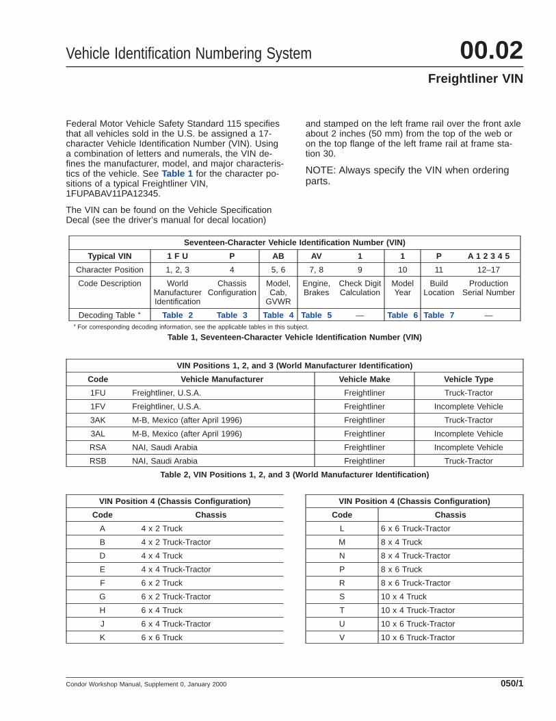
Federal Motor Vehicle Safety Standard 115 specifiesthat all vehicles sold in the U.S. be assigned a 17-character Vehicle Identification Number (VIN). Usinga combination of letters and numerals, the VIN de-fines the manufacturer, model, and major characteris-tics of the vehicle. See Table 1 for the character po-sitions of a typical Freightliner VIN,1FUPABAV11PA12345.
The VIN can be found on the Vehicle SpecificationDecal (see the driver’s manual for decal location)
and stamped on the left frame rail over the front axleabout 2 inches (50 mm) from the top of the web oron the top flange of the left frame rail at frame sta-tion 30.
NOTE: Always specify the VIN when orderingparts.
Seventeen-Character Vehicle Identification Number (VIN)
Typical VIN 1 F U P AB AV 1 1 P A 1 2 3 4 5
Character Position 1, 2, 3 4 5, 6 7, 8 9 10 11 12–17
Code Description WorldManufacturerIdentification
ChassisConfiguration
Model,Cab,
GVWR
Engine,Brakes
Check DigitCalculation
ModelYear
BuildLocation
ProductionSerial Number
Decoding Table * Table 2 Table 3 Table 4 Table 5 — Table 6 Table 7 —* For corresponding decoding information, see the applicable tables in this subject.
Table 1, Seventeen-Character Vehicle Identification Number (VIN)
VIN Positions 1, 2, and 3 (World Manufacturer Identification)
Code Vehicle Manufacturer Vehicle Make Vehicle Type
1FU Freightliner, U.S.A. Freightliner Truck-Tractor
1FV Freightliner, U.S.A. Freightliner Incomplete Vehicle
3AK M-B, Mexico (after April 1996) Freightliner Truck-Tractor
3AL M-B, Mexico (after April 1996) Freightliner Incomplete Vehicle
RSA NAI, Saudi Arabia Freightliner Incomplete Vehicle
RSB NAI, Saudi Arabia Freightliner Truck-Tractor
Table 2, VIN Positions 1, 2, and 3 (World Manufacturer Identification)
VIN Position 4 (Chassis Configuration)
Code Chassis
A 4 x 2 Truck
B 4 x 2 Truck-Tractor
D 4 x 4 Truck
E 4 x 4 Truck-Tractor
F 6 x 2 Truck
G 6 x 2 Truck-Tractor
H 6 x 4 Truck
J 6 x 4 Truck-Tractor
K 6 x 6 Truck
VIN Position 4 (Chassis Configuration)
Code Chassis
L 6 x 6 Truck-Tractor
M 8 x 4 Truck
N 8 x 4 Truck-Tractor
P 8 x 6 Truck
R 8 x 6 Truck-Tractor
S 10 x 4 Truck
T 10 x 4 Truck-Tractor
U 10 x 6 Truck-Tractor
V 10 x 6 Truck-Tractor
Vehicle Identification Numbering System 00.02Freightliner VIN
Condor Workshop Manual, Supplement 0, January 2000 050/1
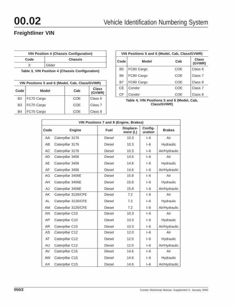
VIN Position 4 (Chassis Configuration)
Code Chassis
X Glider
Table 3, VIN Position 4 (Chassis Configuration)
VIN Positions 5 and 6 (Model, Cab, Class/GVWR)
Code Model Cab Class(GVWR)
B2
B3
B4
FC70 Cargo
FC70 Cargo
FC70 Cargo
COE
COE
COE
Class 6
Class 7
Class 8
VIN Positions 5 and 6 (Model, Cab, Class/GVWR)
Code Model Cab Class(GVWR)
B5
B6
B7
FC80 Cargo
FC80 Cargo
FC80 Cargo
COE
COE
COE
Class 6
Class 7
Class 8
CE
CF
Condor
Condor
COE
COE
Class 7
Class 8
Table 4, VIN Positions 5 and 6 (Model, Cab,Class/GVWR)
VIN Positions 7 and 8 (Engine, Brakes)
Code Engine Fuel Displace-ment (L)
Config-uration Brakes
AA
AB
AC
Caterpillar 3176
Caterpillar 3176
Caterpillar 3176
Diesel
Diesel
Diesel
10.3
10.3
10.3
I–6
I–6
I–6
Air
Hydraulic
Air/Hydraulic
AD
AE
AF
Caterpillar 3406
Caterpillar 3406
Caterpillar 3406
Diesel
Diesel
Diesel
14.6
14.6
14.6
I–6
I–6
I–6
Air
Hydraulic
Air/Hydraulic
AG
AH
AJ
Caterpillar 3406E
Caterpillar 3406E
Caterpillar 3406E
Diesel
Diesel
Diesel
15.8
15.8
15.8
I–6
I–6
I–6
Air
Hydraulic
Air/Hydraulic
AK
AL
AM
Caterpillar 3126/CFE
Caterpillar 3126/CFE
Caterpillar 3126/CFE
Diesel
Diesel
Diesel
7.2
7.2
7.2
I–6
I–6
I–6
Air
Hydraulic
Air/Hydraulic
AN
AP
AR
Caterpillar C10
Caterpillar C10
Caterpillar C10
Diesel
Diesel
Diesel
10.3
10.3
10.3
I–6
I–6
I–6
Air
Hydraulic
Air/Hydraulic
AS
AT
AU
Caterpillar C12
Caterpillar C12
Caterpillar C12
Diesel
Diesel
Diesel
12.0
12.0
12.0
I–6
I–6
I–6
Air
Hydraulic
Air/Hydraulic
AV
AW
AX
Caterpillar C15
Caterpillar C15
Caterpillar C15
Diesel
Diesel
Diesel
14.6
14.6
14.6
I–6
I–6
I–6
Air
Hydraulic
Air/Hydraulic
Vehicle Identification Numbering System00.02Freightliner VIN
Condor Workshop Manual, Supplement 0, January 2000050/2
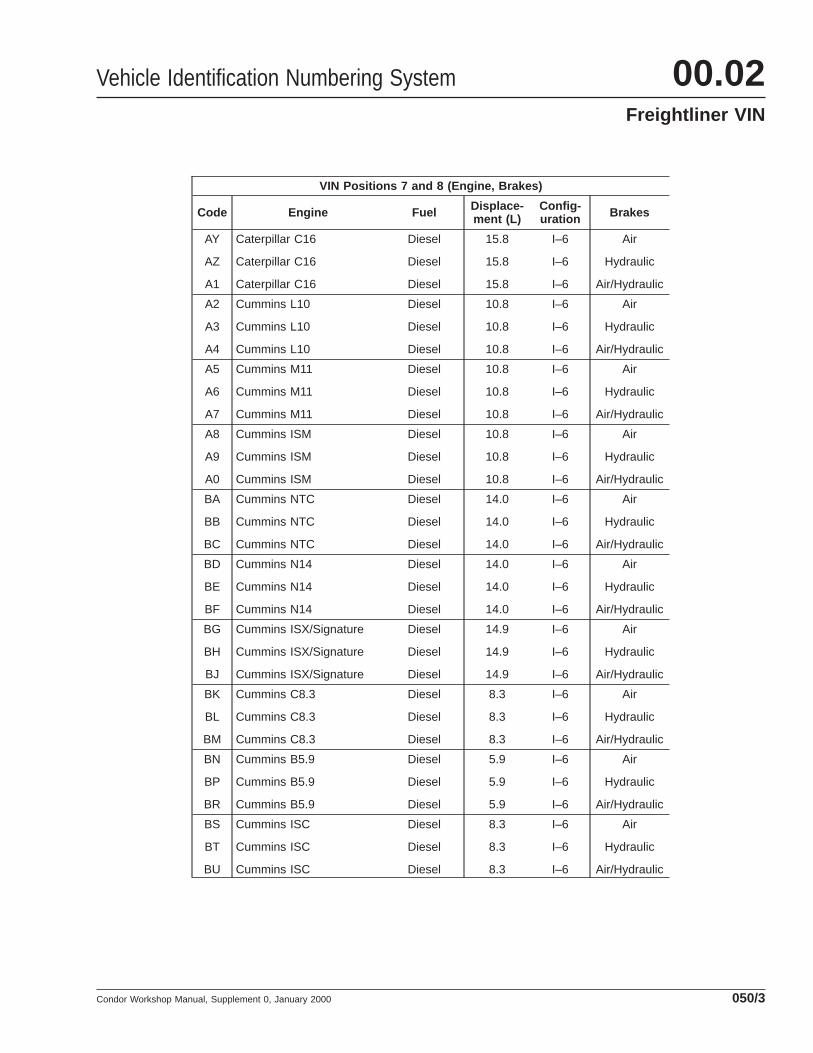
VIN Positions 7 and 8 (Engine, Brakes)
Code Engine Fuel Displace-ment (L)
Config-uration Brakes
AY
AZ
A1
Caterpillar C16
Caterpillar C16
Caterpillar C16
Diesel
Diesel
Diesel
15.8
15.8
15.8
I–6
I–6
I–6
Air
Hydraulic
Air/Hydraulic
A2
A3
A4
Cummins L10
Cummins L10
Cummins L10
Diesel
Diesel
Diesel
10.8
10.8
10.8
I–6
I–6
I–6
Air
Hydraulic
Air/Hydraulic
A5
A6
A7
Cummins M11
Cummins M11
Cummins M11
Diesel
Diesel
Diesel
10.8
10.8
10.8
I–6
I–6
I–6
Air
Hydraulic
Air/Hydraulic
A8
A9
A0
Cummins ISM
Cummins ISM
Cummins ISM
Diesel
Diesel
Diesel
10.8
10.8
10.8
I–6
I–6
I–6
Air
Hydraulic
Air/Hydraulic
BA
BB
BC
Cummins NTC
Cummins NTC
Cummins NTC
Diesel
Diesel
Diesel
14.0
14.0
14.0
I–6
I–6
I–6
Air
Hydraulic
Air/Hydraulic
BD
BE
BF
Cummins N14
Cummins N14
Cummins N14
Diesel
Diesel
Diesel
14.0
14.0
14.0
I–6
I–6
I–6
Air
Hydraulic
Air/Hydraulic
BG
BH
BJ
Cummins ISX/Signature
Cummins ISX/Signature
Cummins ISX/Signature
Diesel
Diesel
Diesel
14.9
14.9
14.9
I–6
I–6
I–6
Air
Hydraulic
Air/Hydraulic
BK
BL
BM
Cummins C8.3
Cummins C8.3
Cummins C8.3
Diesel
Diesel
Diesel
8.3
8.3
8.3
I–6
I–6
I–6
Air
Hydraulic
Air/Hydraulic
BN
BP
BR
Cummins B5.9
Cummins B5.9
Cummins B5.9
Diesel
Diesel
Diesel
5.9
5.9
5.9
I–6
I–6
I–6
Air
Hydraulic
Air/Hydraulic
BS
BT
BU
Cummins ISC
Cummins ISC
Cummins ISC
Diesel
Diesel
Diesel
8.3
8.3
8.3
I–6
I–6
I–6
Air
Hydraulic
Air/Hydraulic
Vehicle Identification Numbering System 00.02Freightliner VIN
Condor Workshop Manual, Supplement 0, January 2000 050/3
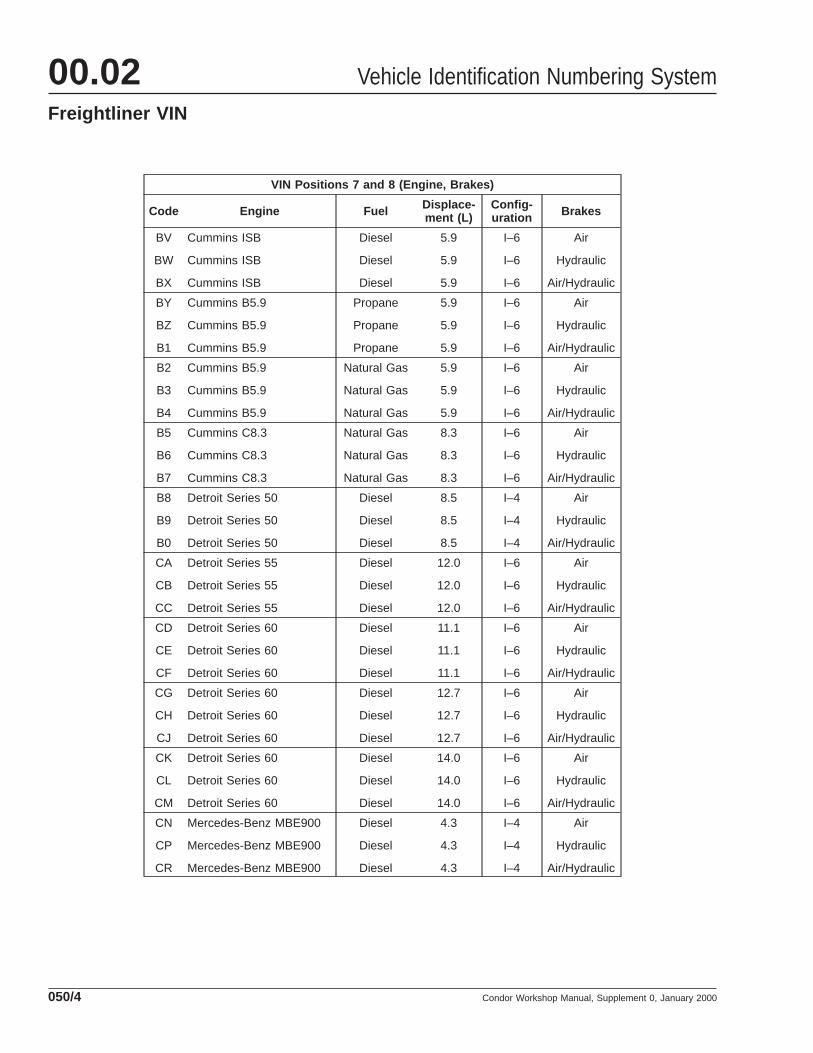
VIN Positions 7 and 8 (Engine, Brakes)
Code Engine Fuel Displace-ment (L)
Config-uration Brakes
BV
BW
BX
Cummins ISB
Cummins ISB
Cummins ISB
Diesel
Diesel
Diesel
5.9
5.9
5.9
I–6
I–6
I–6
Air
Hydraulic
Air/Hydraulic
BY
BZ
B1
Cummins B5.9
Cummins B5.9
Cummins B5.9
Propane
Propane
Propane
5.9
5.9
5.9
I–6
I–6
I–6
Air
Hydraulic
Air/Hydraulic
B2
B3
B4
Cummins B5.9
Cummins B5.9
Cummins B5.9
Natural Gas
Natural Gas
Natural Gas
5.9
5.9
5.9
I–6
I–6
I–6
Air
Hydraulic
Air/Hydraulic
B5
B6
B7
Cummins C8.3
Cummins C8.3
Cummins C8.3
Natural Gas
Natural Gas
Natural Gas
8.3
8.3
8.3
I–6
I–6
I–6
Air
Hydraulic
Air/Hydraulic
B8
B9
B0
Detroit Series 50
Detroit Series 50
Detroit Series 50
Diesel
Diesel
Diesel
8.5
8.5
8.5
I–4
I–4
I–4
Air
Hydraulic
Air/Hydraulic
CA
CB
CC
Detroit Series 55
Detroit Series 55
Detroit Series 55
Diesel
Diesel
Diesel
12.0
12.0
12.0
I–6
I–6
I–6
Air
Hydraulic
Air/Hydraulic
CD
CE
CF
Detroit Series 60
Detroit Series 60
Detroit Series 60
Diesel
Diesel
Diesel
11.1
11.1
11.1
I–6
I–6
I–6
Air
Hydraulic
Air/Hydraulic
CG
CH
CJ
Detroit Series 60
Detroit Series 60
Detroit Series 60
Diesel
Diesel
Diesel
12.7
12.7
12.7
I–6
I–6
I–6
Air
Hydraulic
Air/Hydraulic
CK
CL
CM
Detroit Series 60
Detroit Series 60
Detroit Series 60
Diesel
Diesel
Diesel
14.0
14.0
14.0
I–6
I–6
I–6
Air
Hydraulic
Air/Hydraulic
CN
CP
CR
Mercedes-Benz MBE900
Mercedes-Benz MBE900
Mercedes-Benz MBE900
Diesel
Diesel
Diesel
4.3
4.3
4.3
I–4
I–4
I–4
Air
Hydraulic
Air/Hydraulic
Vehicle Identification Numbering System00.02Freightliner VIN
Condor Workshop Manual, Supplement 0, January 2000050/4
VIN Positions 7 and 8 (Engine, Brakes)
Code Engine Fuel Displace-ment (L)
Config-uration Brakes
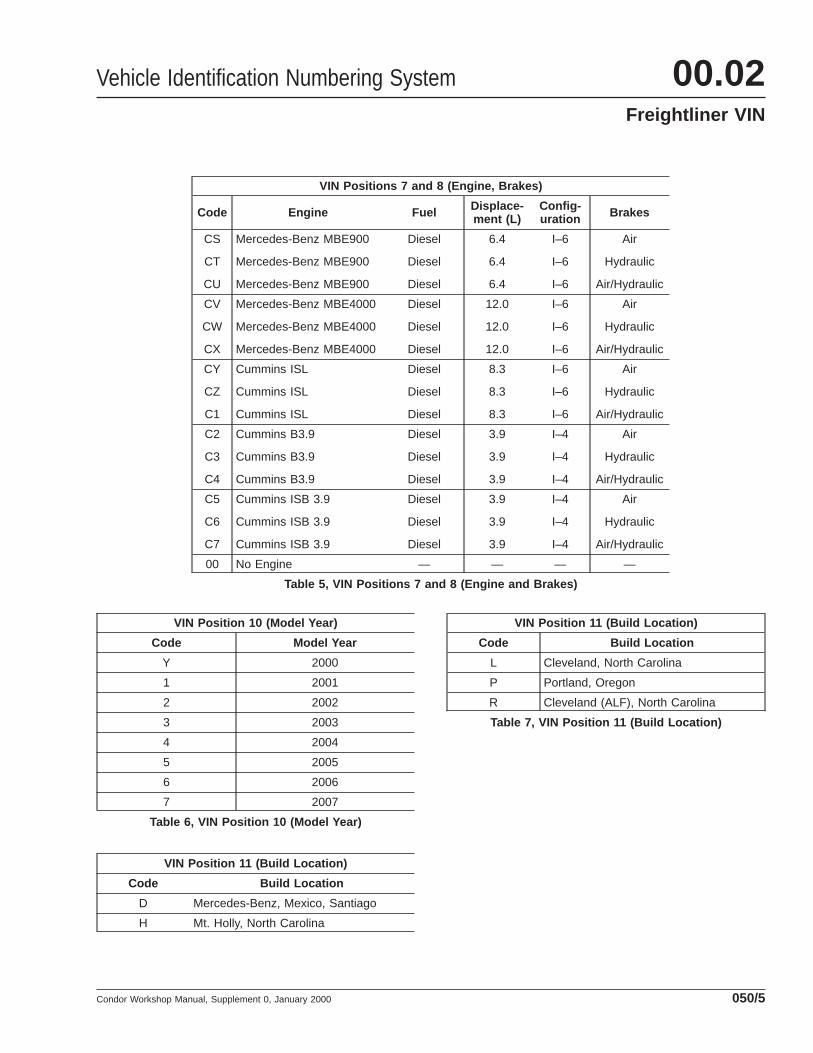
CS
CT
CU
Mercedes-Benz MBE900
Mercedes-Benz MBE900
Mercedes-Benz MBE900
Diesel
Diesel
Diesel
6.4
6.4
6.4
I–6
I–6
I–6
Air
Hydraulic
Air/Hydraulic
CV
CW
CX
Mercedes-Benz MBE4000
Mercedes-Benz MBE4000
Mercedes-Benz MBE4000
Diesel
Diesel
Diesel
12.0
12.0
12.0
I–6
I–6
I–6
Air
Hydraulic
Air/Hydraulic
CY
CZ
C1
Cummins ISL
Cummins ISL
Cummins ISL
Diesel
Diesel
Diesel
8.3
8.3
8.3
I–6
I–6
I–6
Air
Hydraulic
Air/Hydraulic
C2
C3
C4
Cummins B3.9
Cummins B3.9
Cummins B3.9
Diesel
Diesel
Diesel
3.9
3.9
3.9
I–4
I–4
I–4
Air
Hydraulic
Air/Hydraulic
C5
C6
C7
Cummins ISB 3.9
Cummins ISB 3.9
Cummins ISB 3.9
Diesel
Diesel
Diesel
3.9
3.9
3.9
I–4
I–4
I–4
Air
Hydraulic
Air/Hydraulic
00 No Engine — — — —
Table 5, VIN Positions 7 and 8 (Engine and Brakes)
VIN Position 10 (Model Year)
Code Model Year
Y 2000
1 2001
2 2002
3 2003
4 2004
5 2005
6 2006
7 2007
Table 6, VIN Position 10 (Model Year)
VIN Position 11 (Build Location)
Code Build Location
D Mercedes-Benz, Mexico, Santiago
H Mt. Holly, North Carolina
VIN Position 11 (Build Location)
Code Build Location
L Cleveland, North Carolina
P Portland, Oregon
R Cleveland (ALF), North Carolina
Table 7, VIN Position 11 (Build Location)
Vehicle Identification Numbering System 00.02Freightliner VIN
Condor Workshop Manual, Supplement 0, January 2000 050/5
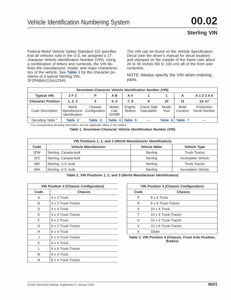
Federal Motor Vehicle Safety Standard 115 specifiesthat all vehicles sold in the U.S. be assigned a 17-character Vehicle Identification Number (VIN). Usinga combination of letters and numerals, the VIN de-fines the manufacturer, model, and major characteris-tics of the vehicle. See Table 1 for the character po-sitions of a typical Sterling VIN,2FZPABAV11AA12345.
The VIN can be found on the Vehicle SpecificationDecal (see the driver’s manual for decal location)and stamped on the outside of the frame rails about24 to 40 inches (60 to 100 cm) aft of the front axlecenterline.
NOTE: Always specify the VIN when orderingparts.
Seventeen-Character Vehicle Identification Number (VIN)
Typical VIN 2 F Z P A B A V 1 1 A A 1 2 3 4 5
Character Position 1, 2, 3 4 5, 6 7, 8 9 10 11 12–17
Code DescriptionWorld
ManufacturerIdentification
ChassisConfiguration
Model,Cab,
GVWR
Engine,Brakes
Check DigitCalculation
ModelYear
BuildLocation
ProductionSerial Number
Decoding Table * Table 2 Table 3 Table 4 Table 5 — Table 6 Table 7 —* For corresponding decoding information, see the applicable tables in this subject.
Table 1, Seventeen-Character Vehicle Identification Number (VIN)
VIN Positions 1, 2, and 3 (World Manufacturer Identification)
Code Vehicle Manufacturer Vehicle Make Vehicle Type
2FW Sterling, Canada-built Sterling Truck-Tractor
2FZ Sterling, Canada-built Sterling Incomplete Vehicle
480 Sterling, U.S.-built Sterling Truck-Tractor
49H Sterling, U.S.-built Sterling Incomplete Vehicle
Table 2, VIN Positions 1, 2, and 3 (World Manufacturer Identification)
VIN Position 4 (Chassis Configuration)
Code Chassis
A 4 x 2 Truck
B 4 x 2 Truck-Tractor
D 4 x 4 Truck
E 4 x 4 Truck-Tractor
F 6 x 2 Truck
G 6 x 2 Truck-Tractor
H 6 x 4 Truck
J 6 x 4 Truck-Tractor
K 6 x 6 Truck
L 6 x 6 Truck-Tractor
M 8 x 4 Truck
N 8 x 4 Truck-Tractor
VIN Position 4 (Chassis Configuration)
Code Chassis
P 8 x 6 Truck
R 8 x 6 Truck-Tractor
S 10 x 4 Truck
T 10 x 4 Truck-Tractor
U 10 x 6 Truck-Tractor
V 10 x 6 Truck-Tractor
X Glider
Table 3, VIN Position 4 (Chassis, Front Axle Position,Brakes)
Vehicle Identification Numbering System 00.02Sterling VIN
Condor Workshop Manual, Supplement 0, January 2000 060/1
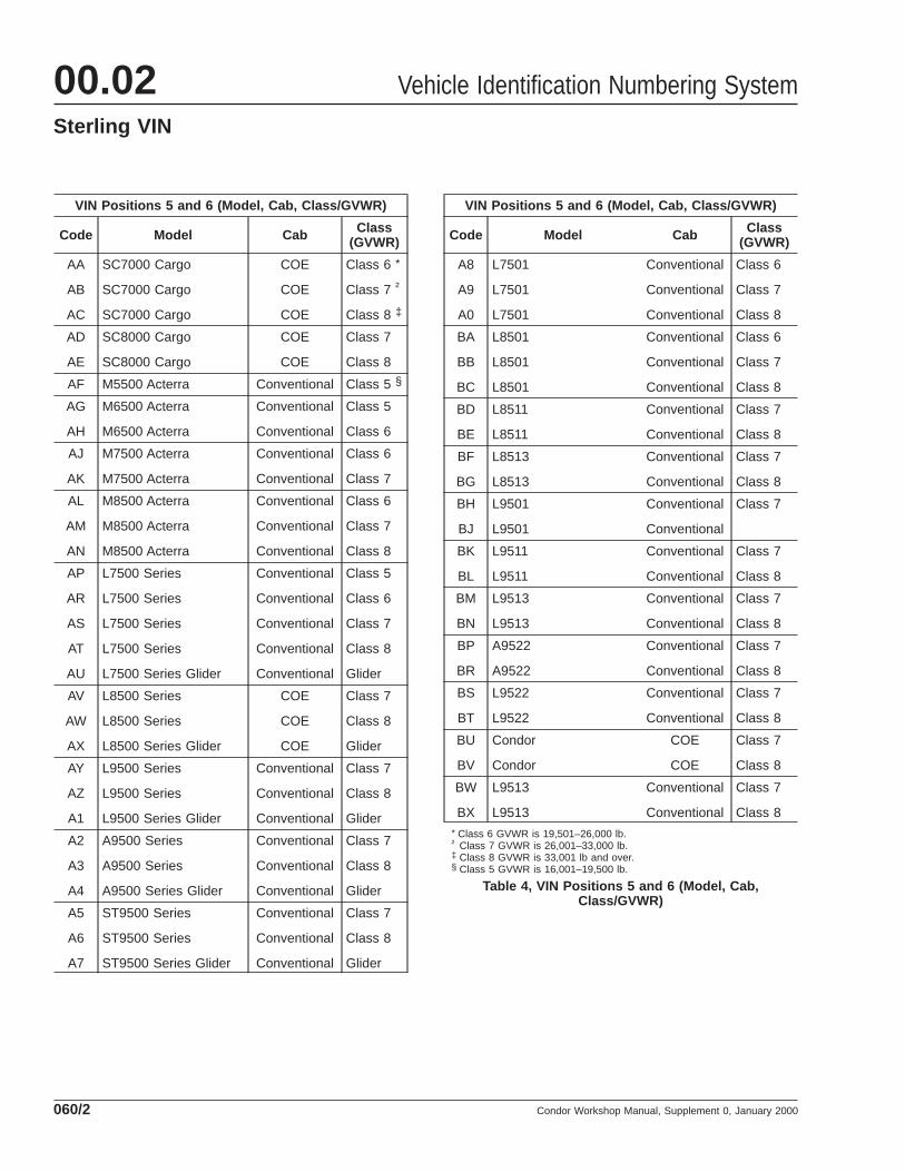
VIN Positions 5 and 6 (Model, Cab, Class/GVWR)
Code Model Cab Class(GVWR)
AA
AB
AC
SC7000 Cargo
SC7000 Cargo
SC7000 Cargo
COE
COE
COE
Class 6 *
Class 7 †
Class 8 ‡
AD
AE
SC8000 Cargo
SC8000 Cargo
COE
COE
Class 7
Class 8
AF M5500 Acterra Conventional Class 5 §
AG
AH
M6500 Acterra
M6500 Acterra
Conventional
Conventional
Class 5
Class 6
AJ
AK
M7500 Acterra
M7500 Acterra
Conventional
Conventional
Class 6
Class 7
AL
AM
AN
M8500 Acterra
M8500 Acterra
M8500 Acterra
Conventional
Conventional
Conventional
Class 6
Class 7
Class 8
AP
AR
AS
AT
AU
L7500 Series
L7500 Series
L7500 Series
L7500 Series
L7500 Series Glider
Conventional
Conventional
Conventional
Conventional
Conventional
Class 5
Class 6
Class 7
Class 8
Glider
AV
AW
AX
L8500 Series
L8500 Series
L8500 Series Glider
COE
COE
COE
Class 7
Class 8
Glider
AY
AZ
A1
L9500 Series
L9500 Series
L9500 Series Glider
Conventional
Conventional
Conventional
Class 7
Class 8
Glider
A2
A3
A4
A9500 Series
A9500 Series
A9500 Series Glider
Conventional
Conventional
Conventional
Class 7
Class 8
Glider
A5
A6
A7
ST9500 Series
ST9500 Series
ST9500 Series Glider
Conventional
Conventional
Conventional
Class 7
Class 8
Glider
VIN Positions 5 and 6 (Model, Cab, Class/GVWR)
Code Model Cab Class(GVWR)
A8
A9
A0
L7501
L7501
L7501
Conventional
Conventional
Conventional
Class 6
Class 7
Class 8
BA
BB
BC
L8501
L8501
L8501
Conventional
Conventional
Conventional
Class 6
Class 7
Class 8
BD
BE
L8511
L8511
Conventional
Conventional
Class 7
Class 8
BF
BG
L8513
L8513
Conventional
Conventional
Class 7
Class 8
BH
BJ
L9501
L9501
Conventional
Conventional
Class 7
BK
BL
L9511
L9511
Conventional
Conventional
Class 7
Class 8
BM
BN
L9513
L9513
Conventional
Conventional
Class 7
Class 8
BP
BR
A9522
A9522
Conventional
Conventional
Class 7
Class 8
BS
BT
L9522
L9522
Conventional
Conventional
Class 7
Class 8
BU
BV
Condor
Condor
COE
COE
Class 7
Class 8
BW
BX
L9513
L9513
Conventional
Conventional
Class 7
Class 8* Class 6 GVWR is 19,501–26,000 lb.† Class 7 GVWR is 26,001–33,000 lb.‡ Class 8 GVWR is 33,001 lb and over.§ Class 5 GVWR is 16,001–19,500 lb.
Table 4, VIN Positions 5 and 6 (Model, Cab,Class/GVWR)
Vehicle Identification Numbering System00.02Sterling VIN
Condor Workshop Manual, Supplement 0, January 2000060/2
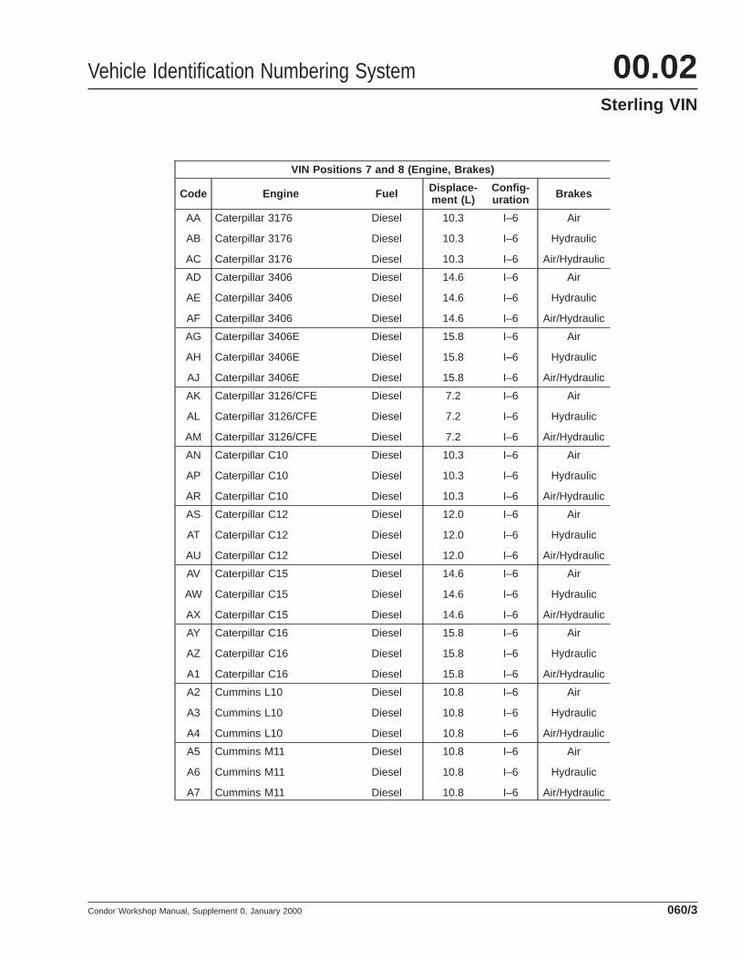
VIN Positions 7 and 8 (Engine, Brakes)
Code Engine Fuel Displace-ment (L)
Config-uration Brakes
AA
AB
AC
Caterpillar 3176
Caterpillar 3176
Caterpillar 3176
Diesel
Diesel
Diesel
10.3
10.3
10.3
I–6
I–6
I–6
Air
Hydraulic
Air/Hydraulic
AD
AE
AF
Caterpillar 3406
Caterpillar 3406
Caterpillar 3406
Diesel
Diesel
Diesel
14.6
14.6
14.6
I–6
I–6
I–6
Air
Hydraulic
Air/Hydraulic
AG
AH
AJ
Caterpillar 3406E
Caterpillar 3406E
Caterpillar 3406E
Diesel
Diesel
Diesel
15.8
15.8
15.8
I–6
I–6
I–6
Air
Hydraulic
Air/Hydraulic
AK
AL
AM
Caterpillar 3126/CFE
Caterpillar 3126/CFE
Caterpillar 3126/CFE
Diesel
Diesel
Diesel
7.2
7.2
7.2
I–6
I–6
I–6
Air
Hydraulic
Air/Hydraulic
AN
AP
AR
Caterpillar C10
Caterpillar C10
Caterpillar C10
Diesel
Diesel
Diesel
10.3
10.3
10.3
I–6
I–6
I–6
Air
Hydraulic
Air/Hydraulic
AS
AT
AU
Caterpillar C12
Caterpillar C12
Caterpillar C12
Diesel
Diesel
Diesel
12.0
12.0
12.0
I–6
I–6
I–6
Air
Hydraulic
Air/Hydraulic
AV
AW
AX
Caterpillar C15
Caterpillar C15
Caterpillar C15
Diesel
Diesel
Diesel
14.6
14.6
14.6
I–6
I–6
I–6
Air
Hydraulic
Air/Hydraulic
AY
AZ
A1
Caterpillar C16
Caterpillar C16
Caterpillar C16
Diesel
Diesel
Diesel
15.8
15.8
15.8
I–6
I–6
I–6
Air
Hydraulic
Air/Hydraulic
A2
A3
A4
Cummins L10
Cummins L10
Cummins L10
Diesel
Diesel
Diesel
10.8
10.8
10.8
I–6
I–6
I–6
Air
Hydraulic
Air/Hydraulic
A5
A6
A7
Cummins M11
Cummins M11
Cummins M11
Diesel
Diesel
Diesel
10.8
10.8
10.8
I–6
I–6
I–6
Air
Hydraulic
Air/Hydraulic
Vehicle Identification Numbering System 00.02Sterling VIN
Condor Workshop Manual, Supplement 0, January 2000 060/3
VIN Positions 7 and 8 (Engine, Brakes)
Code Engine Fuel Displace-ment (L)
Config-uration Brakes
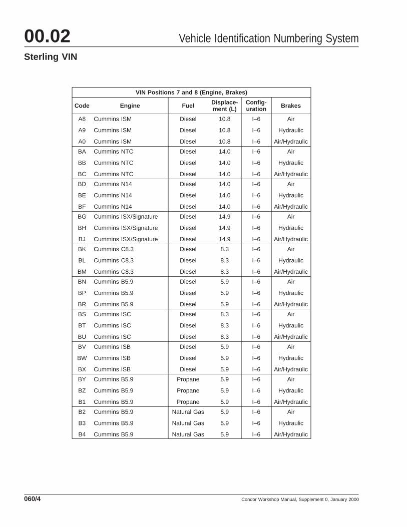
A8
A9
A0
Cummins ISM
Cummins ISM
Cummins ISM
Diesel
Diesel
Diesel
10.8
10.8
10.8
I–6
I–6
I–6
Air
Hydraulic
Air/Hydraulic
BA
BB
BC
Cummins NTC
Cummins NTC
Cummins NTC
Diesel
Diesel
Diesel
14.0
14.0
14.0
I–6
I–6
I–6
Air
Hydraulic
Air/Hydraulic
BD
BE
BF
Cummins N14
Cummins N14
Cummins N14
Diesel
Diesel
Diesel
14.0
14.0
14.0
I–6
I–6
I–6
Air
Hydraulic
Air/Hydraulic
BG
BH
BJ
Cummins ISX/Signature
Cummins ISX/Signature
Cummins ISX/Signature
Diesel
Diesel
Diesel
14.9
14.9
14.9
I–6
I–6
I–6
Air
Hydraulic
Air/Hydraulic
BK
BL
BM
Cummins C8.3
Cummins C8.3
Cummins C8.3
Diesel
Diesel
Diesel
8.3
8.3
8.3
I–6
I–6
I–6
Air
Hydraulic
Air/Hydraulic
BN
BP
BR
Cummins B5.9
Cummins B5.9
Cummins B5.9
Diesel
Diesel
Diesel
5.9
5.9
5.9
I–6
I–6
I–6
Air
Hydraulic
Air/Hydraulic
BS
BT
BU
Cummins ISC
Cummins ISC
Cummins ISC
Diesel
Diesel
Diesel
8.3
8.3
8.3
I–6
I–6
I–6
Air
Hydraulic
Air/Hydraulic
BV
BW
BX
Cummins ISB
Cummins ISB
Cummins ISB
Diesel
Diesel
Diesel
5.9
5.9
5.9
I–6
I–6
I–6
Air
Hydraulic
Air/Hydraulic
BY
BZ
B1
Cummins B5.9
Cummins B5.9
Cummins B5.9
Propane
Propane
Propane
5.9
5.9
5.9
I–6
I–6
I–6
Air
Hydraulic
Air/Hydraulic
B2
B3
B4
Cummins B5.9
Cummins B5.9
Cummins B5.9
Natural Gas
Natural Gas
Natural Gas
5.9
5.9
5.9
I–6
I–6
I–6
Air
Hydraulic
Air/Hydraulic
Vehicle Identification Numbering System00.02Sterling VIN
Condor Workshop Manual, Supplement 0, January 2000060/4
VIN Positions 7 and 8 (Engine, Brakes)
Code Engine Fuel Displace-ment (L)
Config-uration Brakes
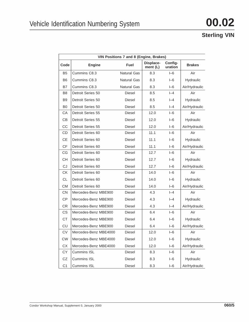
B5
B6
B7
Cummins C8.3
Cummins C8.3
Cummins C8.3
Natural Gas
Natural Gas
Natural Gas
8.3
8.3
8.3
I–6
I–6
I–6
Air
Hydraulic
Air/Hydraulic
B8
B9
B0
Detroit Series 50
Detroit Series 50
Detroit Series 50
Diesel
Diesel
Diesel
8.5
8.5
8.5
I–4
I–4
I–4
Air
Hydraulic
Air/Hydraulic
CA
CB
CC
Detroit Series 55
Detroit Series 55
Detroit Series 55
Diesel
Diesel
Diesel
12.0
12.0
12.0
I–6
I–6
I–6
Air
Hydraulic
Air/Hydraulic
CD
CE
CF
Detroit Series 60
Detroit Series 60
Detroit Series 60
Diesel
Diesel
Diesel
11.1
11.1
11.1
I–6
I–6
I–6
Air
Hydraulic
Air/Hydraulic
CG
CH
CJ
Detroit Series 60
Detroit Series 60
Detroit Series 60
Diesel
Diesel
Diesel
12.7
12.7
12.7
I–6
I–6
I–6
Air
Hydraulic
Air/Hydraulic
CK
CL
CM
Detroit Series 60
Detroit Series 60
Detroit Series 60
Diesel
Diesel
Diesel
14.0
14.0
14.0
I–6
I–6
I–6
Air
Hydraulic
Air/Hydraulic
CN
CP
CR
Mercedes-Benz MBE900
Mercedes-Benz MBE900
Mercedes-Benz MBE900
Diesel
Diesel
Diesel
4.3
4.3
4.3
I–4
I–4
I–4
Air
Hydraulic
Air/Hydraulic
CS
CT
CU
Mercedes-Benz MBE900
Mercedes-Benz MBE900
Mercedes-Benz MBE900
Diesel
Diesel
Diesel
6.4
6.4
6.4
I–6
I–6
I–6
Air
Hydraulic
Air/Hydraulic
CV
CW
CX
Mercedes-Benz MBE4000
Mercedes-Benz MBE4000
Mercedes-Benz MBE4000
Diesel
Diesel
Diesel
12.0
12.0
12.0
I–6
I–6
I–6
Air
Hydraulic
Air/Hydraulic
CY
CZ
C1
Cummins ISL
Cummins ISL
Cummins ISL
Diesel
Diesel
Diesel
8.3
8.3
8.3
I–6
I–6
I–6
Air
Hydraulic
Air/Hydraulic
Vehicle Identification Numbering System 00.02Sterling VIN
Condor Workshop Manual, Supplement 0, January 2000 060/5
VIN Positions 7 and 8 (Engine, Brakes)
Code Engine Fuel Displace-ment (L)
Config-uration Brakes
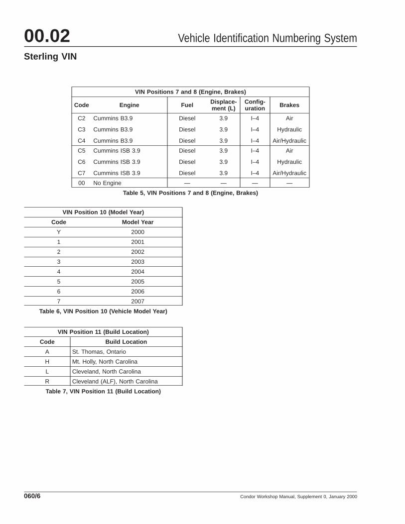
C2
C3
C4
Cummins B3.9
Cummins B3.9
Cummins B3.9
Diesel
Diesel
Diesel
3.9
3.9
3.9
I–4
I–4
I–4
Air
Hydraulic
Air/Hydraulic
C5
C6
C7
Cummins ISB 3.9
Cummins ISB 3.9
Cummins ISB 3.9
Diesel
Diesel
Diesel
3.9
3.9
3.9
I–4
I–4
I–4
Air
Hydraulic
Air/Hydraulic
00 No Engine — — — —
Table 5, VIN Positions 7 and 8 (Engine, Brakes)
VIN Position 10 (Model Year)
Code Model Year
Y 2000
1 2001
2 2002
3 2003
4 2004
5 2005
6 2006
7 2007
Table 6, VIN Position 10 (Vehicle Model Year)
VIN Position 11 (Build Location)
Code Build Location
A St. Thomas, Ontario
H Mt. Holly, North Carolina
L Cleveland, North Carolina
R Cleveland (ALF), North Carolina
Table 7, VIN Position 11 (Build Location)
Vehicle Identification Numbering System00.02Sterling VIN
Condor Workshop Manual, Supplement 0, January 2000060/6
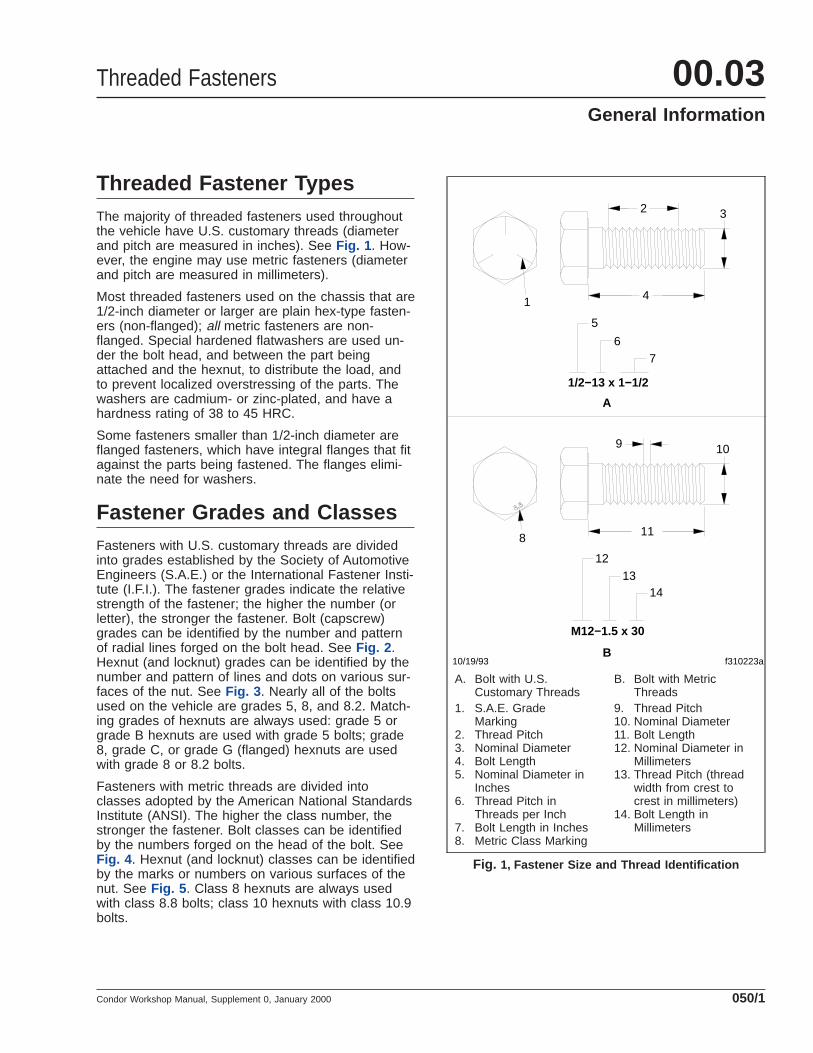
Threaded Fastener TypesThe majority of threaded fasteners used throughoutthe vehicle have U.S. customary threads (diameterand pitch are measured in inches). See Fig. 1 . How-ever, the engine may use metric fasteners (diameterand pitch are measured in millimeters).
Most threaded fasteners used on the chassis that are1/2-inch diameter or larger are plain hex-type fasten-ers (non-flanged); all metric fasteners are non-flanged. Special hardened flatwashers are used un-der the bolt head, and between the part beingattached and the hexnut, to distribute the load, andto prevent localized overstressing of the parts. Thewashers are cadmium- or zinc-plated, and have ahardness rating of 38 to 45 HRC.
Some fasteners smaller than 1/2-inch diameter areflanged fasteners, which have integral flanges that fitagainst the parts being fastened. The flanges elimi-nate the need for washers.
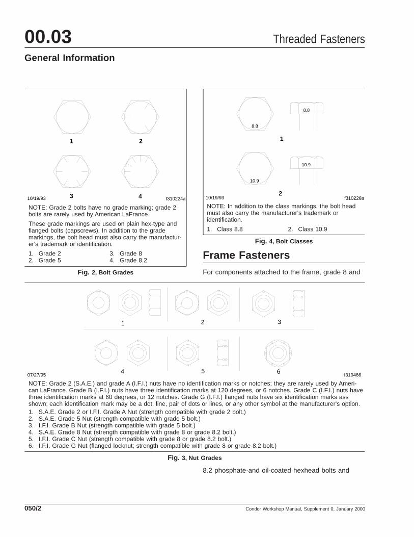
Fastener Grades and ClassesFasteners with U.S. customary threads are dividedinto grades established by the Society of AutomotiveEngineers (S.A.E.) or the International Fastener Insti-tute (I.F.I.). The fastener grades indicate the relativestrength of the fastener; the higher the number (orletter), the stronger the fastener. Bolt (capscrew)grades can be identified by the number and patternof radial lines forged on the bolt head. See Fig. 2 .Hexnut (and locknut) grades can be identified by thenumber and pattern of lines and dots on various sur-faces of the nut. See Fig. 3 . Nearly all of the boltsused on the vehicle are grades 5, 8, and 8.2. Match-ing grades of hexnuts are always used: grade 5 orgrade B hexnuts are used with grade 5 bolts; grade8, grade C, or grade G (flanged) hexnuts are usedwith grade 8 or 8.2 bolts.
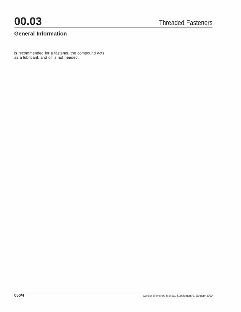
Fasteners with metric threads are divided intoclasses adopted by the American National StandardsInstitute (ANSI). The higher the class number, thestronger the fastener. Bolt classes can be identifiedby the numbers forged on the head of the bolt. SeeFig. 4 . Hexnut (and locknut) classes can be identifiedby the marks or numbers on various surfaces of thenut. See Fig. 5 . Class 8 hexnuts are always usedwith class 8.8 bolts; class 10 hexnuts with class 10.9bolts.
M12−1.5 x 30
1/2−13 x 1−1/2
f310223a10/19/93
1
2 3
4
5
67
8
9 10
11
12
1314
A
B
A. Bolt with U.S.Customary Threads
B. Bolt with MetricThreads
1. S.A.E. GradeMarking
2. Thread Pitch3. Nominal Diameter4. Bolt Length5. Nominal Diameter in
Inches6. Thread Pitch in
Threads per Inch7. Bolt Length in Inches8. Metric Class Marking
9. Thread Pitch10. Nominal Diameter11. Bolt Length12. Nominal Diameter in
Millimeters13. Thread Pitch (thread
width from crest tocrest in millimeters)
14. Bolt Length inMillimeters
Fig. 1, Fastener Size and Thread Identification
Threaded Fasteners 00.03General Information
Condor Workshop Manual, Supplement 0, January 2000 050/1
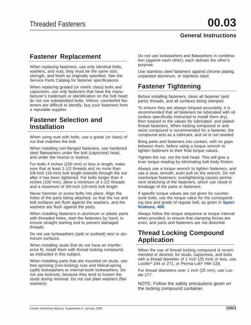
Frame FastenersFor components attached to the frame, grade 8 and
8.2 phosphate-and oil-coated hexhead bolts and
f310224a 3
1
4
2
10/19/93
NOTE: Grade 2 bolts have no grade marking; grade 2bolts are rarely used by American LaFrance.
These grade markings are used on plain hex-type andflanged bolts (capscrews). In addition to the grademarkings, the bolt head must also carry the manufactur-er’s trademark or identification.
1. Grade 22. Grade 5
3. Grade 84. Grade 8.2
Fig. 2, Bolt Grades
1 2 3
4 5 6 07/27/95 f310466
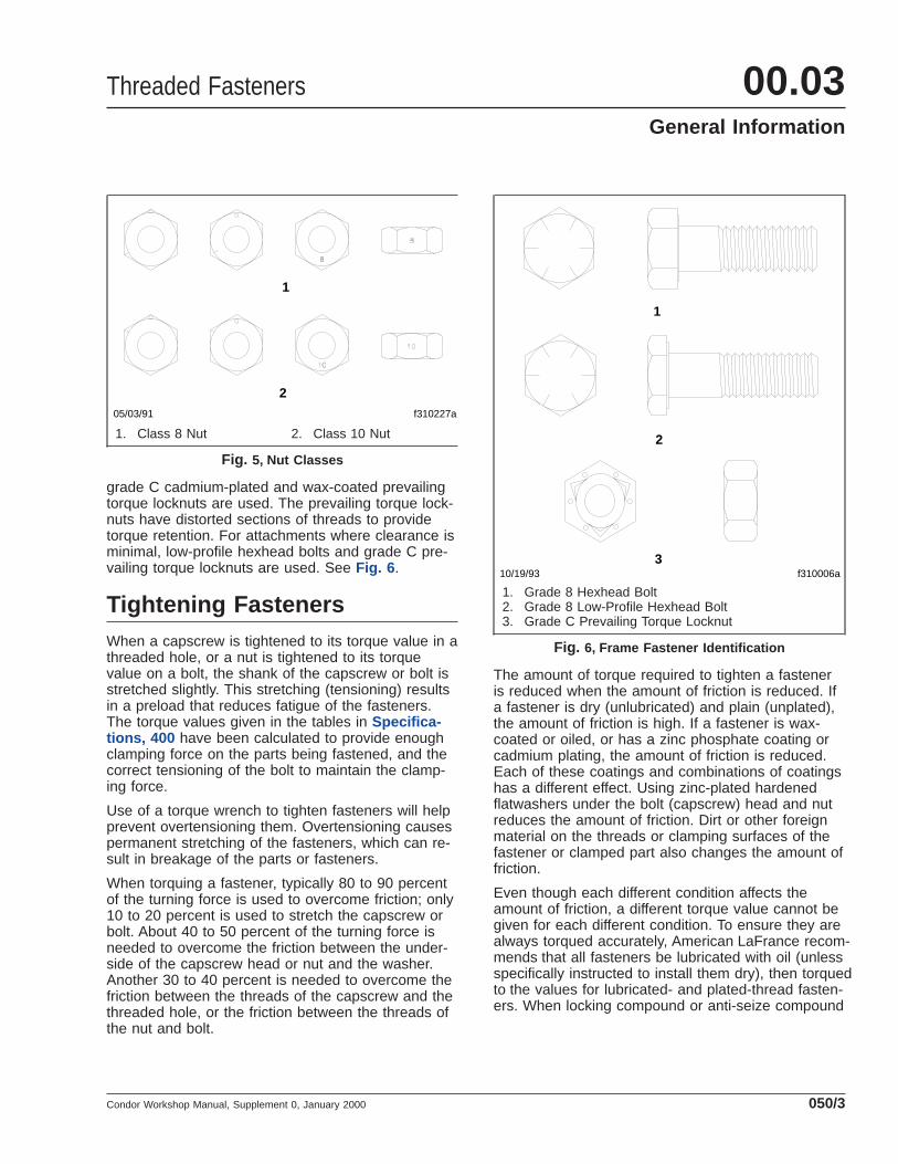
NOTE: Grade 2 (S.A.E.) and grade A (I.F.I.) nuts have no identification marks or notches; they are rarely used by Ameri-can LaFrance. Grade B (I.F.I.) nuts have three identification marks at 120 degrees, or 6 notches. Grade C (I.F.I.) nuts havethree identification marks at 60 degrees, or 12 notches. Grade G (I.F.I.) flanged nuts have six identification marks assshown; each identification mark may be a dot, line, pair of dots or lines, or any other symbol at the manufacturer’s option.1. S.A.E. Grade 2 or I.F.I. Grade A Nut (strength compatible with grade 2 bolt.)2. S.A.E. Grade 5 Nut (strength compatible with grade 5 bolt.)3. I.F.I. Grade B Nut (strength compatible with grade 5 bolt.)4. S.A.E. Grade 8 Nut (strength compatible with grade 8 or grade 8.2 bolt.)5. I.F.I. Grade C Nut (strength compatible with grade 8 or grade 8.2 bolt.)6. I.F.I. Grade G Nut (flanged locknut; strength compatible with grade 8 or grade 8.2 bolt.)
Fig. 3, Nut Grades
8.8
10.9
8.8
10.9
1
2f310226a10/19/93
NOTE: In addition to the class markings, the bolt headmust also carry the manufacturer’s trademark oridentification.
1. Class 8.8 2. Class 10.9
Fig. 4, Bolt Classes
Threaded Fasteners00.03General Information
Condor Workshop Manual, Supplement 0, January 2000050/2
grade C cadmium-plated and wax-coated prevailingtorque locknuts are used. The prevailing torque lock-nuts have distorted sections of threads to providetorque retention. For attachments where clearance isminimal, low-profile hexhead bolts and grade C pre-vailing torque locknuts are used. See Fig. 6 .
Tightening FastenersWhen a capscrew is tightened to its torque value in athreaded hole, or a nut is tightened to its torquevalue on a bolt, the shank of the capscrew or bolt isstretched slightly. This stretching (tensioning) resultsin a preload that reduces fatigue of the fasteners.The torque values given in the tables in Specifica-tions, 400 have been calculated to provide enoughclamping force on the parts being fastened, and thecorrect tensioning of the bolt to maintain the clamp-ing force.
Use of a torque wrench to tighten fasteners will helpprevent overtensioning them. Overtensioning causespermanent stretching of the fasteners, which can re-sult in breakage of the parts or fasteners.
When torquing a fastener, typically 80 to 90 percentof the turning force is used to overcome friction; only10 to 20 percent is used to stretch the capscrew orbolt. About 40 to 50 percent of the turning force isneeded to overcome the friction between the under-side of the capscrew head or nut and the washer.Another 30 to 40 percent is needed to overcome thefriction between the threads of the capscrew and thethreaded hole, or the friction between the threads ofthe nut and bolt.
The amount of torque required to tighten a fasteneris reduced when the amount of friction is reduced. Ifa fastener is dry (unlubricated) and plain (unplated),the amount of friction is high. If a fastener is wax-coated or oiled, or has a zinc phosphate coating orcadmium plating, the amount of friction is reduced.Each of these coatings and combinations of coatingshas a different effect. Using zinc-plated hardenedflatwashers under the bolt (capscrew) head and nutreduces the amount of friction. Dirt or other foreignmaterial on the threads or clamping surfaces of thefastener or clamped part also changes the amount offriction.
Even though each different condition affects theamount of friction, a different torque value cannot begiven for each different condition. To ensure they arealways torqued accurately, American LaFrance recom-mends that all fasteners be lubricated with oil (unlessspecifically instructed to install them dry), then torquedto the values for lubricated- and plated-thread fasten-ers. When locking compound or anti-seize compound
1
2
f310227a05/03/91
1. Class 8 Nut 2. Class 10 Nut
Fig. 5, Nut Classes
f310006a 10/19/93
1
2
3
1. Grade 8 Hexhead Bolt2. Grade 8 Low-Profile Hexhead Bolt3. Grade C Prevailing Torque Locknut
Fig. 6, Frame Fastener Identification
Threaded Fasteners 00.03General Information
Condor Workshop Manual, Supplement 0, January 2000 050/3
is recommended for a fastener, the compound actsas a lubricant, and oil is not needed.
Threaded Fasteners00.03General Information
Condor Workshop Manual, Supplement 0, January 2000050/4
Fastener ReplacementWhen replacing fasteners, use only identical bolts,washers, and nuts; they must be the same size,strength, and finish as originally specified. See theService Parts Catalog for fastener specifications.
When replacing graded (or metric class) bolts andcapscrews, use only fasteners that have the manu-facturer’s trademark or identification on the bolt head;do not use substandard bolts. Inferior, counterfeit fas-teners are difficult to identify; buy your fasteners froma reputable supplier.
Fastener Selection andInstallationWhen using nuts with bolts, use a grade (or class) ofnut that matches the bolt.
When installing non-flanged fasteners, use hardenedsteel flatwashers under the bolt (capscrew) head,and under the hexnut or locknut.
For bolts 4 inches (100 mm) or less in length, makesure that at least 1-1/2 threads and no more than5/8-inch (16-mm) bolt length extends through the nutafter it has been tightened. For bolts longer than 4inches (100 mm), allow a minimum of 1-1/2 threadsand a maximum of 3/4-inch (19-mm) bolt length.
Never hammer or screw bolts into place. Align theholes of the parts being attached, so that the nut andbolt surfaces are flush against the washers, and thewashers are flush against the parts.
When installing fasteners in aluminum or plastic partswith threaded holes, start the fasteners by hand, toensure straight starting and to prevent damagedthreads.
Do not use lockwashers (split or toothed) next to alu-minum surfaces.
When installing studs that do not have an interfer-ence fit, install them with thread locking compound,as instructed in this subject.
When installing parts that are mounted on studs, usefree-spinning (non-locking) nuts and helical-spring(split) lockwashers or internal-tooth lockwashers. Donot use locknuts, because they tend to loosen thestuds during removal. Do not use plain washers (flat-washers).
Do not use lockwashers and flatwashers in combina-tion (against each other); each defeats the other’spurpose.
Use stainless steel fasteners against chrome plating,unpainted aluminum, or stainless steel.
Fastener TighteningBefore installing fasteners, clean all fastener (andparts) threads, and all surfaces being clamped.
To ensure they are always torqued accurately, it isrecommended that all fasteners be lubricated with oil(unless specifically instructed to install them dry),then torqued to the values for lubricated- and plated-thread fasteners. When locking compound or anti-seize compound is recommended for a fastener, thecompound acts as a lubricant, and oil is not needed.
Bring parts and fasteners into contact, with no gapsbetween them, before using a torque wrench totighten fasteners to their final torque values.
Tighten the nut, not the bolt head. This will give atruer torque reading by eliminating bolt body friction.
Always use a torque wrench to tighten fasteners, anduse a slow, smooth, even pull on the wrench. Do notovertorque fasteners; overtightening causes perma-nent stretching of the fasteners, which can result inbreakage of the parts or fasteners.
If specific torque values are not given for counter-sunk bolts, use the torque value for the correspond-ing size and grade of regular bolt, as given in Speci-fications, 400 .
Always follow the torque sequence or torque intervalwhen provided, to ensure that clamping forces areeven, and parts and fasteners are not distorted.
Thread Locking CompoundApplicationWhen the use of thread locking compound is recom-mended or desired, for studs, capscrews, and boltswith a thread diameter of 1 inch (25 mm) or less, useLoctite® 244 or 271, or Perma-Lok® HM–128.
For thread diameters over 1 inch (25 mm), use Loc-tite 277.
NOTE: Follow the safety precautions given onthe locking compound container.
Threaded Fasteners 00.03General Instructions
Condor Workshop Manual, Supplement 0, January 2000 100/1
1. Clean the male and female threads of the fasten-ers, removing all dirt, oil, and other foreign mate-rial. If parts are contaminated, use Stoddard sol-vent for cleaning; then allow the fasteners to airdry for 10 minutes. Be sure solvent is completelygone before applying adhesive.
2. Transfer a small amount of the locking com-pound from the container to a paper cup or smallnon-metal dish.
3. Using a plastic brush (a metal brush will contami-nate the compound), apply a small amount ofcompound to the entire circumference of 3 or 4of the male threads that will be covered by thenut after it has been tightened. Be sure enoughcompound is applied to fill the inside of the nutthreads, with a slight excess.
4. Install and torque the nut. Readjustment of thenut position is not possible after installation iscomplete, without destroying the locking effect.
NOTE: To disassemble the fasteners, heat thebond line to 400°F (200°C) before removing thenut. Every time the fasteners are disassembled,replace them. If any parts are damaged by over-heating, replace the parts.
Threaded Fasteners00.03General Instructions
Condor Workshop Manual, Supplement 0, January 2000100/2
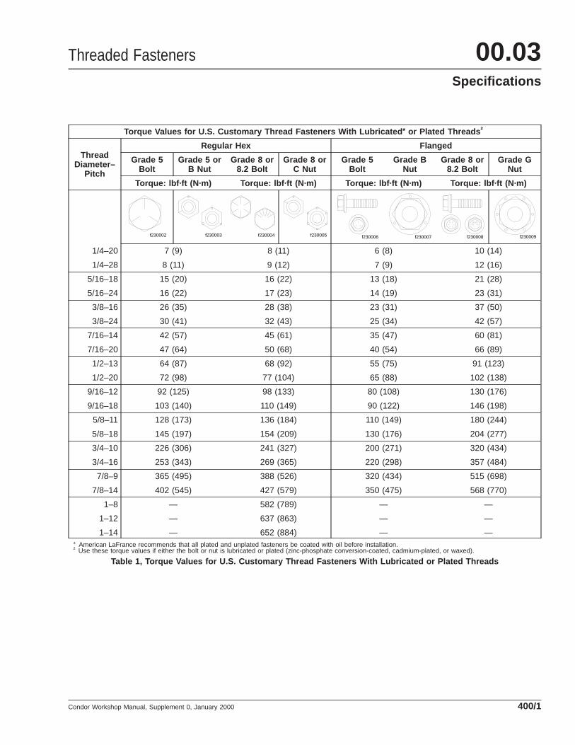
Torque Values for U.S. Customary Thread Fasteners With Lubricated * or Plated Threads †
ThreadDiameter–
Pitch
Regular Hex Flanged
Grade 5Bolt
Grade 5 orB Nut
Grade 8 or8.2 Bolt
Grade 8 orC Nut
Grade 5Bolt
Grade BNut
Grade 8 or8.2 Bolt
Grade GNut
Torque: lbf·ft (N·m) Torque: lbf·ft (N·m) Torque: lbf·ft (N·m) Torque: lbf·ft (N·m)
1/4–20
f230002 f230003 f230004 f230005 f230006 f230007 f230008 f230009
7 (9) 8 (11) 6 (8) 10 (14)
1/4–28 8 (11) 9 (12) 7 (9) 12 (16)
5/16–18 15 (20) 16 (22) 13 (18) 21 (28)
5/16–24 16 (22) 17 (23) 14 (19) 23 (31)
3/8–16 26 (35) 28 (38) 23 (31) 37 (50)
3/8–24 30 (41) 32 (43) 25 (34) 42 (57)
7/16–14 42 (57) 45 (61) 35 (47) 60 (81)
7/16–20 47 (64) 50 (68) 40 (54) 66 (89)
1/2–13 64 (87) 68 (92) 55 (75) 91 (123)
1/2–20 72 (98) 77 (104) 65 (88) 102 (138)
9/16–12 92 (125) 98 (133) 80 (108) 130 (176)
9/16–18 103 (140) 110 (149) 90 (122) 146 (198)
5/8–11 128 (173) 136 (184) 110 (149) 180 (244)
5/8–18 145 (197) 154 (209) 130 (176) 204 (277)
3/4–10 226 (306) 241 (327) 200 (271) 320 (434)
3/4–16 253 (343) 269 (365) 220 (298) 357 (484)
7/8–9 365 (495) 388 (526) 320 (434) 515 (698)
7/8–14 402 (545) 427 (579) 350 (475) 568 (770)
1–8 — 582 (789) — —
1–12 — 637 (863) — —
1–14 — 652 (884) — —* American LaFrance recommends that all plated and unplated fasteners be coated with oil before installation.† Use these torque values if either the bolt or nut is lubricated or plated (zinc-phosphate conversion-coated, cadmium-plated, or waxed).
Table 1, Torque Values for U.S. Customary Thread Fasteners With Lubricated or Plated Threads
Threaded Fasteners 00.03Specifications
Condor Workshop Manual, Supplement 0, January 2000 400/1
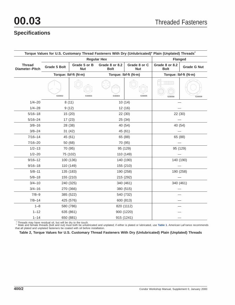
Torque Values for U.S. Customary Thread Fasteners With Dry (Unlubricated) * Plain (Unplated) Threads †
ThreadDiameter–Pitch
Regular Hex Flanged
Grade 5 Bolt Grade 5 or BNut
Grade 8 or 8.2Bolt
Grade 8 or CNut
Grade 8 or 8.2Bolt Grade G Nut
Torque: lbf·ft (N·m) Torque: lbf·ft (N·m) Torque: lbf·ft (N·m)
1/4–20
f230002 f230003 f230004 f230005 f230008 f230009
8 (11) 10 (14) —
1/4–28 9 (12) 12 (16) —
5/16–18 15 (20) 22 (30) 22 (30)
5/16–24 17 (23) 25 (34) —
3/8–16 28 (38) 40 (54) 40 (54)
3/8–24 31 (42) 45 (61) —
7/16–14 45 (61) 65 (88) 65 (88)
7/16–20 50 (68) 70 (95) —
1/2–13 70 (95) 95 (129) 95 (129)
1/2–20 75 (102) 110 (149) —
9/16–12 100 (136) 140 (190) 140 (190)
9/16–18 110 (149) 155 (210) —
5/8–11 135 (183) 190 (258) 190 (258)
5/8–18 155 (210) 215 (292) —
3/4–10 240 (325) 340 (461) 340 (461)
3/4–16 270 (366) 380 (515) —
7/8–9 385 (522) 540 (732) —
7/8–14 425 (576) 600 (813) —
1–8 580 (786) 820 (1112) —
1–12 635 (861) 900 (1220) —
1–14 650 (881) 915 (1241) —* Threads may have residual oil, but will be dry to the touch.† Male and female threads (bolt and nut) must both be unlubricated and unplated; if either is plated or lubricated, use Table 1 . American LaFrance recommendsthat all plated and unplated fasteners be coated with oil before installation.
Table 2, Torque Values for U.S. Customary Thread Fasteners With Dry (Unlubricated) Plain (Unplated) Threads
Threaded Fasteners00.03Specifications
Condor Workshop Manual, Supplement 0, January 2000400/2
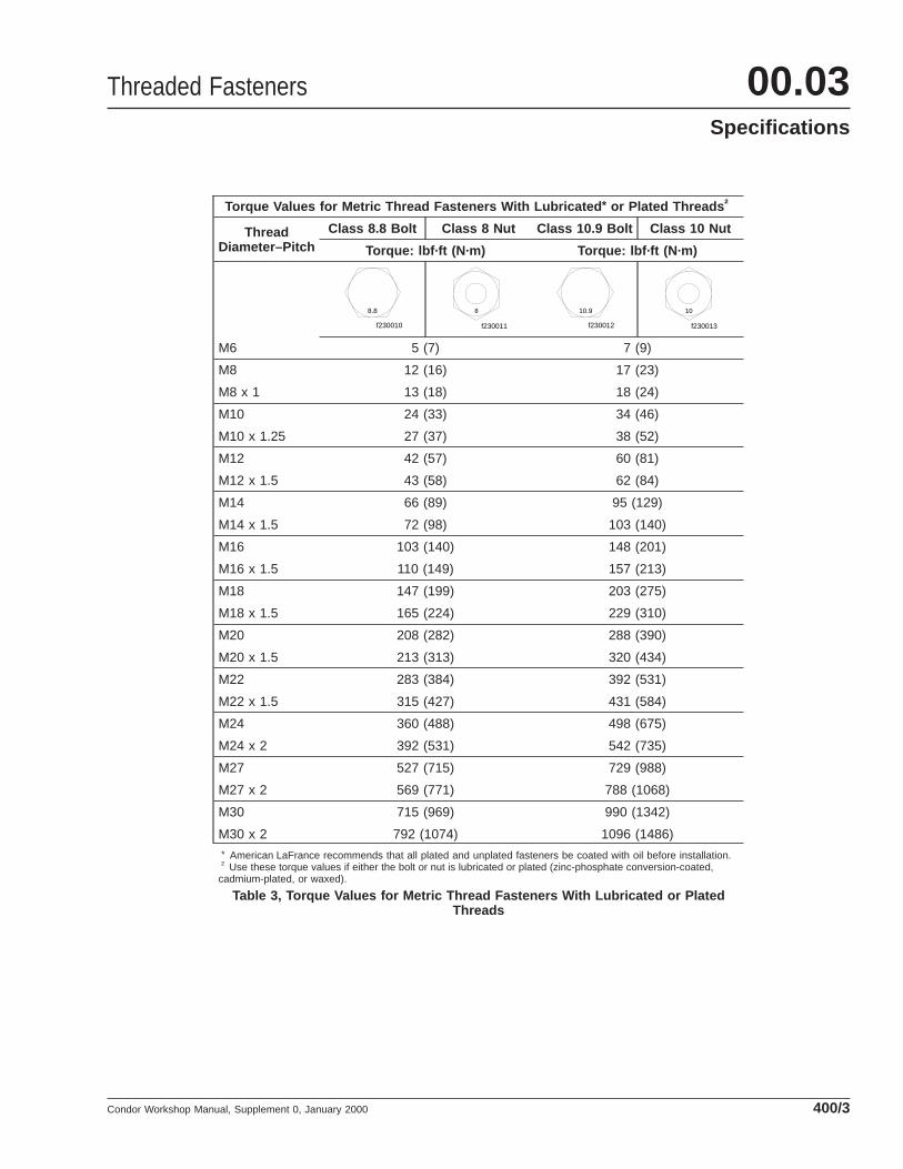
Torque Values for Metric Thread Fasteners With Lubricated * or Plated Threads †
ThreadDiameter–Pitch
Class 8.8 Bolt Class 8 Nut Class 10.9 Bolt Class 10 Nut
Torque: lbf·ft (N·m) Torque: lbf·ft (N·m)
M6
f230010
8.8
f230011
8
f230012
10.9
f230013
10
5 (7) 7 (9)
M8 12 (16) 17 (23)
M8 x 1 13 (18) 18 (24)
M10 24 (33) 34 (46)
M10 x 1.25 27 (37) 38 (52)
M12 42 (57) 60 (81)
M12 x 1.5 43 (58) 62 (84)
M14 66 (89) 95 (129)
M14 x 1.5 72 (98) 103 (140)
M16 103 (140) 148 (201)
M16 x 1.5 110 (149) 157 (213)
M18 147 (199) 203 (275)
M18 x 1.5 165 (224) 229 (310)
M20 208 (282) 288 (390)
M20 x 1.5 213 (313) 320 (434)
M22 283 (384) 392 (531)
M22 x 1.5 315 (427) 431 (584)
M24 360 (488) 498 (675)
M24 x 2 392 (531) 542 (735)
M27 527 (715) 729 (988)
M27 x 2 569 (771) 788 (1068)
M30 715 (969) 990 (1342)
M30 x 2 792 (1074) 1096 (1486)* American LaFrance recommends that all plated and unplated fasteners be coated with oil before installation.† Use these torque values if either the bolt or nut is lubricated or plated (zinc-phosphate conversion-coated,cadmium-plated, or waxed).
Table 3, Torque Values for Metric Thread Fasteners With Lubricated or PlatedThreads
Threaded Fasteners 00.03Specifications
Condor Workshop Manual, Supplement 0, January 2000 400/3
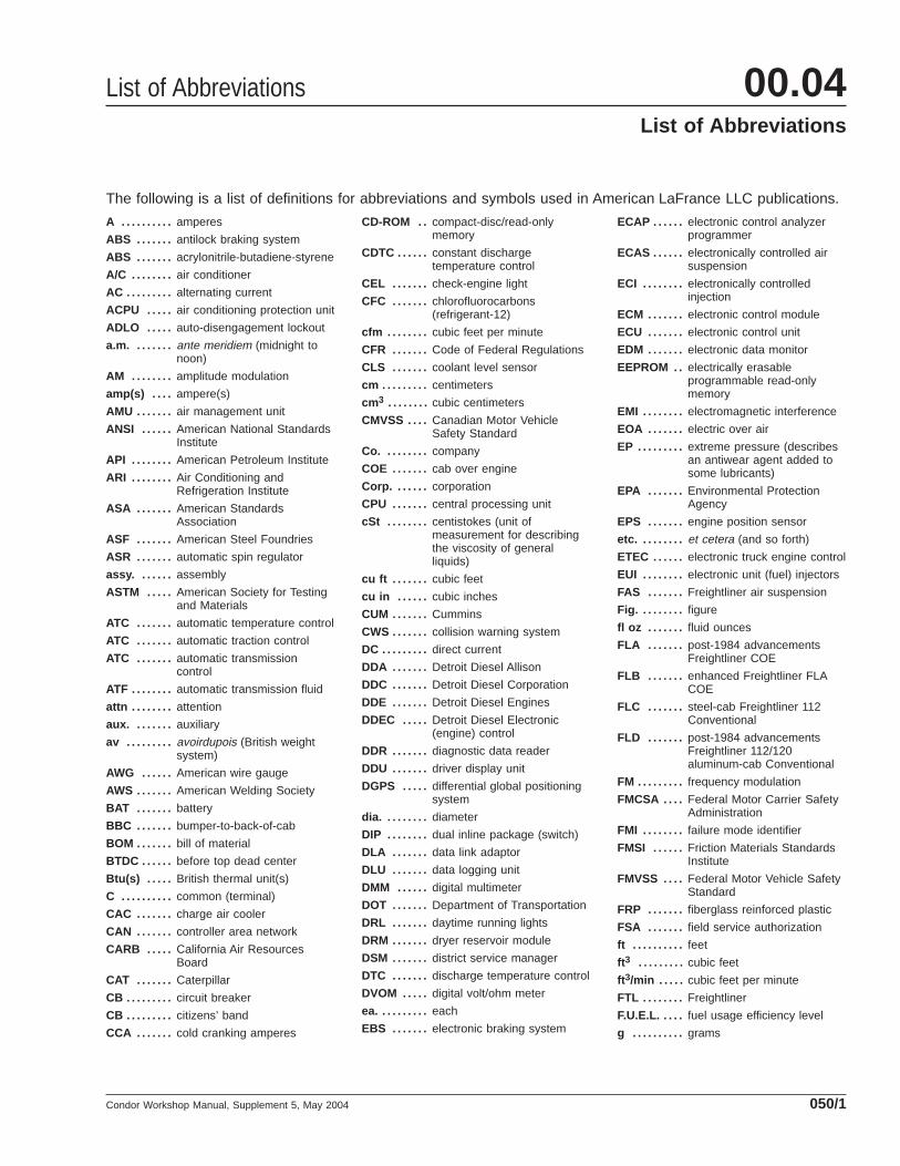
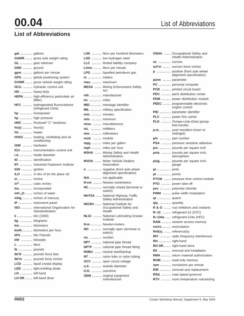
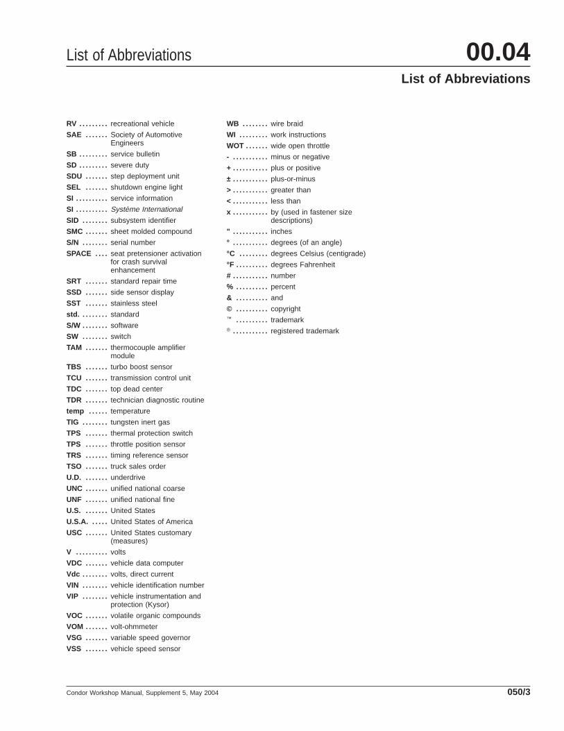
The following is a list of definitions for abbreviations and symbols used in American LaFrance LLC publications.
A . . . . . . . . . . amperes
ABS . . . . . . . antilock braking system
ABS . . . . . . . acrylonitrile-butadiene-styrene
A/C . . . . . . . . air conditioner
AC . . . . . . . . . alternating current
ACPU . . . . . air conditioning protection unit
ADLO . . . . . auto-disengagement lockout
a.m. . . . . . . . ante meridiem (midnight tonoon)
AM . . . . . . . . amplitude modulation
amp(s) . . . . ampere(s)
AMU . . . . . . . air management unit
ANSI . . . . . . American National StandardsInstitute
API . . . . . . . . American Petroleum Institute
ARI . . . . . . . . Air Conditioning andRefrigeration Institute
ASA . . . . . . . American StandardsAssociation
ASF . . . . . . . American Steel Foundries
ASR . . . . . . . automatic spin regulator
assy. . . . . . . assembly
ASTM . . . . . American Society for Testingand Materials
ATC . . . . . . . automatic temperature control
ATC . . . . . . . automatic traction control
ATC . . . . . . . automatic transmissioncontrol
ATF . . . . . . . . automatic transmission fluid
attn . . . . . . . . attention
aux. . . . . . . . auxiliary
av . . . . . . . . . avoirdupois (British weightsystem)
AWG . . . . . . American wire gauge
AWS . . . . . . . American Welding Society
BAT . . . . . . . battery
BBC . . . . . . . bumper-to-back-of-cab
BOM . . . . . . . bill of material
BTDC . . . . . . before top dead center
Btu(s) . . . . . British thermal unit(s)
C . . . . . . . . . . common (terminal)
CAC . . . . . . . charge air cooler
CAN . . . . . . . controller area network
CARB . . . . . California Air ResourcesBoard
CAT . . . . . . . Caterpillar
CB . . . . . . . . . circuit breaker
CB . . . . . . . . . citizens’ band
CCA . . . . . . . cold cranking amperes
CD-ROM . . compact-disc/read-onlymemory
CDTC . . . . . . constant dischargetemperature control
CEL . . . . . . . check-engine light
CFC . . . . . . . chlorofluorocarbons(refrigerant-12)
cfm . . . . . . . . cubic feet per minute
CFR . . . . . . . Code of Federal Regulations
CLS . . . . . . . coolant level sensor
cm . . . . . . . . . centimeters
cm3 . . . . . . . . cubic centimeters
CMVSS . . . . Canadian Motor VehicleSafety Standard
Co. . . . . . . . . company
COE . . . . . . . cab over engine
Corp. . . . . . . corporation
CPU . . . . . . . central processing unit
cSt . . . . . . . . centistokes (unit ofmeasurement for describingthe viscosity of generalliquids)
cu ft . . . . . . . cubic feet
cu in . . . . . . cubic inches
CUM . . . . . . . Cummins
CWS . . . . . . . collision warning system
DC . . . . . . . . . direct current
DDA . . . . . . . Detroit Diesel Allison
DDC . . . . . . . Detroit Diesel Corporation
DDE . . . . . . . Detroit Diesel Engines
DDEC . . . . . Detroit Diesel Electronic(engine) control
DDR . . . . . . . diagnostic data reader
DDU . . . . . . . driver display unit
DGPS . . . . . differential global positioningsystem
dia. . . . . . . . . diameter
DIP . . . . . . . . dual inline package (switch)
DLA . . . . . . . data link adaptor
DLU . . . . . . . data logging unit
DMM . . . . . . digital multimeter
DOT . . . . . . . Department of Transportation
DRL . . . . . . . daytime running lights
DRM . . . . . . . dryer reservoir module
DSM . . . . . . . district service manager
DTC . . . . . . . discharge temperature control
DVOM . . . . . digital volt/ohm meter
ea. . . . . . . . . . each
EBS . . . . . . . electronic braking system
ECAP . . . . . . electronic control analyzerprogrammer
ECAS . . . . . . electronically controlled airsuspension
ECI . . . . . . . . electronically controlledinjection
ECM . . . . . . . electronic control module
ECU . . . . . . . electronic control unit
EDM . . . . . . . electronic data monitor
EEPROM . . electrically erasableprogrammable read-onlymemory
EMI . . . . . . . . electromagnetic interference
EOA . . . . . . . electric over air
EP . . . . . . . . . extreme pressure (describesan antiwear agent added tosome lubricants)
EPA . . . . . . . Environmental ProtectionAgency
EPS . . . . . . . engine position sensor
etc. . . . . . . . . et cetera (and so forth)
ETEC . . . . . . electronic truck engine control
EUI . . . . . . . . electronic unit (fuel) injectors
FAS . . . . . . . Freightliner air suspension
Fig. . . . . . . . . figure
fl oz . . . . . . . fluid ounces
FLA . . . . . . . post-1984 advancementsFreightliner COE
FLB . . . . . . . enhanced Freightliner FLACOE
FLC . . . . . . . steel-cab Freightliner 112Conventional
FLD . . . . . . . post-1984 advancementsFreightliner 112/120aluminum-cab Conventional
FM . . . . . . . . . frequency modulation
FMCSA . . . . Federal Motor Carrier SafetyAdministration
FMI . . . . . . . . failure mode identifier
FMSI . . . . . . Friction Materials StandardsInstitute
FMVSS . . . . Federal Motor Vehicle SafetyStandard
FRP . . . . . . . fiberglass reinforced plastic
FSA . . . . . . . field service authorization
ft . . . . . . . . . . feet
ft 3 . . . . . . . . . cubic feet
ft 3/min . . . . . cubic feet per minute
FTL . . . . . . . . Freightliner
F.U.E.L. . . . . fuel usage efficiency level
g . . . . . . . . . . grams
List of Abbreviations 00.04List of Abbreviations
Condor Workshop Manual, Supplement 5, May 2004 050/1
gal . . . . . . . . . gallons
GAWR . . . . . gross axle weight rating
GL . . . . . . . . . gear lubricant
GND . . . . . . . ground
gpm . . . . . . . gallons per minute
GPS . . . . . . . global positioning system
GVWR . . . . . gross vehicle weight rating
HCU . . . . . . . hydraulic control unit
HD . . . . . . . . . heavy-duty
HEPA . . . . . . high-efficiency particulate air(filter)
HFC . . . . . . . hydrogenated fluorocarbons(refrigerant-134a)
hp . . . . . . . . . horsepower
hp . . . . . . . . . high pressure
HRC . . . . . . . Rockwell "C" hardness
hr(s) . . . . . . . hour(s)
htr . . . . . . . . . heater
HVAC . . . . . . heating, ventilating and airconditioning
H/W . . . . . . . hardware
ICU . . . . . . . . instrumentation control unit
i.d. . . . . . . . . . inside diameter
ID . . . . . . . . . . identification
IFI . . . . . . . . . Industrial Fasteners Institute
IGN . . . . . . . . ignition
ILO . . . . . . . . in lieu of (in the place of)
in . . . . . . . . . . inches
in3 . . . . . . . . . cubic inches
Inc. . . . . . . . . incorporated
inH 2O . . . . . inches of water
inHg . . . . . . . inches of mercury
IP . . . . . . . . . . instrument panel
ISO . . . . . . . . International Organization forStandardization
k . . . . . . . . . . . kilo (1000)
kg . . . . . . . . . kilograms
km . . . . . . . . . kilometers
km/h . . . . . . . kilometers per hour
kPa . . . . . . . . kilo Pascals
kW . . . . . . . . kilowatts
L . . . . . . . . . . liters
lb . . . . . . . . . . pounds
lbf·ft . . . . . . . pounds force feet
lbf·in . . . . . . pounds force inches
LCD . . . . . . . liquid crystal display
LED . . . . . . . light-emitting diode
LH . . . . . . . . . left-hand
LH DR . . . . . left-hand drive
LHK . . . . . . . liters per hundred kilometers
LHS . . . . . . . low hydrogen steel
LLC . . . . . . . limited liability company
L/min . . . . . . liters per minute
LPG . . . . . . . liquefied petroleum gas
m . . . . . . . . . . meters
max. . . . . . . . maximum
MESA . . . . . Mining Enforcement SafetyAct
mfr. . . . . . . . . manufacturer
mi . . . . . . . . . miles
MID . . . . . . . . message identifier
MIL . . . . . . . . military specification
min. . . . . . . . minutes
min. . . . . . . . minimum
misc. . . . . . . miscellaneous
mL . . . . . . . . milliliters
mm . . . . . . . . millimeters
mod. . . . . . . module
mpg . . . . . . . miles per gallon
mph . . . . . . . miles per hour
MSHA . . . . . Mining Safety and HealthAdministration
MVDA . . . . . Motor Vehicle DealersAssociation
n . . . . . . . . . . negative (front axle wheelalignment specification)
N/A . . . . . . . . not applicable
N·cm . . . . . . Newton-centimeters
NC . . . . . . . . . normally closed (terminal orswitch)
NHTSA . . . . National Highway TrafficSafety Administration
NIOSH . . . . . National Institute forOccupational Safety andHealth
NLGI . . . . . . National Lubricating GreaseInstitute
N·m . . . . . . . . Newton-meters
NO . . . . . . . . normally open (terminal orswitch)
no. . . . . . . . . number
NPT . . . . . . . national pipe thread
NPTF . . . . . . national pipe thread fitting
NSBU . . . . . neutral start/backup
NT . . . . . . . . . nylon tube or nylon tubing
OCV . . . . . . . open circuit voltage
o.d. . . . . . . . . outside diameter
O.D. . . . . . . . overdrive
OEM . . . . . . . original equipmentmanufacturer
OSHA . . . . . Occupational Safety andHealth Administration
oz . . . . . . . . . ounces
ozf·in . . . . . . ounces force inches
p . . . . . . . . . . positive (front axle wheelalignment specification)
parm . . . . . . parameter
PC . . . . . . . . . personal computer
PCB . . . . . . . printed circuit board
PDC . . . . . . . parts distribution center
PDM . . . . . . . power distribution module
PEEC . . . . . . programmable electronicengine control
PID . . . . . . . . parameter identifier
PLC . . . . . . . power line carrier
PLD . . . . . . . Pumpe-Linie-Düse (pump-line-nozzle)
p.m. . . . . . . . post meridiem (noon tomidnight)
p/n . . . . . . . . part number
PSA . . . . . . . pressure sensitive adhesive
psi . . . . . . . . . pounds per square inch
psia . . . . . . . pounds per square inch,atmosphere
psig . . . . . . . pounds per square inch,gauge
pt . . . . . . . . . . pints
pt . . . . . . . . . . points
PTCM . . . . . pressure time control module
PTO . . . . . . . power take-off
pvc . . . . . . . . polyvinyl chloride
PWM . . . . . . pulse width modulation
qt . . . . . . . . . . quarts
qty. . . . . . . . . quantity
R & O . . . . . rust inhibitors and oxidants
R–12 . . . . . . refrigerant-12 (CFC)
R–134a . . . . refrigerant-134a (HFC)
RAM . . . . . . . random access memory
recirc . . . . . . recirculation
Ref(s). . . . . . reference(s)
RFI . . . . . . . . radio frequency interference
RH . . . . . . . . . right-hand
RH DR . . . . . right-hand drive
R/I . . . . . . . . . removal and installation
RMA . . . . . . . return material authorization
ROM . . . . . . . read-only memory
rpm . . . . . . . . revolutions per minute
R/R . . . . . . . . removal and replacement
RSG . . . . . . . road speed governor
RTV . . . . . . . room temperature vulcanizing
List of Abbreviations00.04List of Abbreviations
Condor Workshop Manual, Supplement 5, May 2004050/2
RV . . . . . . . . . recreational vehicle
SAE . . . . . . . Society of AutomotiveEngineers
SB . . . . . . . . . service bulletin
SD . . . . . . . . . severe duty
SDU . . . . . . . step deployment unit
SEL . . . . . . . shutdown engine light
SI . . . . . . . . . . service information
SI . . . . . . . . . . Système International
SID . . . . . . . . subsystem identifier
SMC . . . . . . . sheet molded compound
S/N . . . . . . . . serial number
SPACE . . . . seat pretensioner activationfor crash survivalenhancement
SRT . . . . . . . standard repair time
SSD . . . . . . . side sensor display
SST . . . . . . . stainless steel
std. . . . . . . . . standard
S/W . . . . . . . . software
SW . . . . . . . . switch
TAM . . . . . . . thermocouple amplifiermodule
TBS . . . . . . . turbo boost sensor
TCU . . . . . . . transmission control unit
TDC . . . . . . . top dead center
TDR . . . . . . . technician diagnostic routine
temp . . . . . . temperature
TIG . . . . . . . . tungsten inert gas
TPS . . . . . . . thermal protection switch
TPS . . . . . . . throttle position sensor
TRS . . . . . . . timing reference sensor
TSO . . . . . . . truck sales order
U.D. . . . . . . . underdrive
UNC . . . . . . . unified national coarse
UNF . . . . . . . unified national fine
U.S. . . . . . . . United States
U.S.A. . . . . . United States of America
USC . . . . . . . United States customary(measures)
V . . . . . . . . . . volts
VDC . . . . . . . vehicle data computer
Vdc . . . . . . . . volts, direct current
VIN . . . . . . . . vehicle identification number
VIP . . . . . . . . vehicle instrumentation andprotection (Kysor)
VOC . . . . . . . volatile organic compounds
VOM . . . . . . . volt-ohmmeter
VSG . . . . . . . variable speed governor
VSS . . . . . . . vehicle speed sensor
WB . . . . . . . . wire braid
WI . . . . . . . . . work instructions
WOT . . . . . . . wide open throttle
- . . . . . . . . . . . minus or negative
+ . . . . . . . . . . . plus or positive
± . . . . . . . . . . . plus-or-minus
> . . . . . . . . . . . greater than
< . . . . . . . . . . . less than
x . . . . . . . . . . . by (used in fastener sizedescriptions)
" . . . . . . . . . . . inches
° . . . . . . . . . . . degrees (of an angle)
°C . . . . . . . . . degrees Celsius (centigrade)
°F . . . . . . . . . . degrees Fahrenheit
# . . . . . . . . . . . number
% . . . . . . . . . . percent
& . . . . . . . . . . and
© . . . . . . . . . . copyright™ . . . . . . . . . . trademark® . . . . . . . . . . . registered trademark
List of Abbreviations 00.04List of Abbreviations
Condor Workshop Manual, Supplement 5, May 2004 050/3