Embed Size (px)
Citation preview


G e n e r a l i n d u s t r y b e l l o w s v a l v e s a n d 4 s a f e t y c l a s s b e l l o w s v a l v e s f o r n u c l e a r p o w e r p l a n t s
2 a n d 3 s a f e t y c l a s s b e l l o w s v a l v e s f o r n u c l e a r p o w e r p l a n t s

CONTENTS
GENERAL INDUSTRY BELLOWS VALVES AND 4 SAFETY CLASS BELLOWS VALVES FOR NUCLEAR POWER PLANTS
Area of utilization 6 Working conditions 6 Versions 6 General feature 7 Delivery set 7 Valve identification form 8 Valve arrangement 9 Main parts material 10
Table of versions 11 Electric drives table 14 DRAWINGS Valves with shifted branch pipes КЗО 0205 16 Valves with shifted branch pipes and additional gland КЗО 0203 22 Connection dimensions of valves with shifted branch pipes 28 Valves with line branch pipes КЗО 0208 30 Vacuum valves КЗО 0208 36 Valves with line branch pipes and additional gland КЗО 0206 38 Connection dimensions of valves with line branch pipes 44 Angle valves КЗО 0207 46 Connection dimensions of angle valves 48 MASS TABLE 50 The correspondence table of valve versions under ТУ 3742-003-57180370-2005 and figure identifications of Central Constructor Valve Building Bureau 52
2 and 3 SAFETY CLASS VALVES Area of utilization 53 Working conditions 53 General feature 53 Parameters of environment in the hermetic blanket of nuclear power plants 54 Delivery set 54 High pressure valves КЗА 0209 55 Valve identification form 56 Table of versions 57 DRAWINGS AND SPECIFICATIONS 58

CONTENTS (CONTINUE)
Low pressure valves КЗА 0208, КЗА 0210 61 Valve identification form 62 Table of versions 63 DRAWINGS AND SPECIFICATIONS 64
Valves for control equipment КЗА 0204 68
SMALL SERIES VALVES Safety valves ПКП 70 Three-way valves КТХ 72
ADDITIONS Addition 1. Bellows valves factory length (except КЗА 0204) 74 Addition 2. Branch pipe shift value for valves КЗО 0205, КЗА 0208, КЗА 0209 75 Addition 3. Flange drawings and connection dimensions 76 Made-to-order versions produced on demand 78
G E N E R A L I N D U S T R Y B E L L O W S V A L V E S A N D 4 S A F E T Y
C L A S S B E L L O W S V A L V E S F O R N U C L E A R P O W E R P L A N T S
Area of utilization Valves are designed for working as shut-off devices: 1) in 4 class of safety (in compliance with НП-001-97) systems of nuclear power
plants; 2) in general industry systems.
Working conditions
Valves are allowed to be used in the systems with following working medium: - versions made of steel 12Х18Н10Т – nitrogen, ammonia, argon, boric solution,
high-concentrated hydrogen peroxide, potassium hydroxide, sodium hydrochloride, liquid radioactive waste, хлор liquid and gaseous chlorine, oil, odorant, desalinated water, demineralized steam, supply medium, remedium, light oil – gasoline, kerosene, hydrocarbon gas, freon R-134a, freon 141В;
- versions made of steel 10Х17Н13М3Т (10Х17Н13М2Т) – high-concentrated acid solutions, alkali solutions, other corrosive medium;
- versions made of steel 20, 09Г2С – ammonia, hydrogen, air, diesel fuel, top gas, coke oven gas, black oil fuel, oil М-40, methane, desalinated water, steam, associated petroleum gas, propane, extraction water, oil, natural gas, emulsion, methyl spirit, fuel gas, turbine oil, ethyl spirit. Employment of valves in the systems with other medium must be coordinated with the manufacturer.
Valves are allowed to be used at a temperature of environment: - versions made of steel 20 from -40 to +50⁰С;
- versions made of steel 12Х18Н10Т, 10Х17Н13М3Т from -50 to +50⁰С;
- versions made of steel 09Г2С from -60 to +50⁰С
Versions
Nominal diameter: DN3…150. Estimated pressure: 1,0…6,3 MPа, vacuum. Valve modifications:
1) by type (series): - КЗО 0203 – full-flow valves with shifted branch pipes and additional gland (DN6…150); - КЗО 0205 – full-flow valves with shifted branch pipes (DN6…150); - КЗО 0206 – full-flow valves with line branch pipes and additional gland (DN6…150); - КЗО 0207 – angle valves (DN6…150); - КЗО 0208 – full-flow valves with line branch pipes. 2) by control method:
- handle; - articulated coupling (DN10…150); - electric drive (DN10…150).
6

7
3) by type of pipeline connection: - flanged (DN10…150);
- welding (DN6…150); - threaded end (DN3…25).
4) by type of gate seal: - built-up welding ЦН-12М (DN6…150); - polytetrafluorethylene (DN6…150); - rubber (PN10). 5) by body material: - steel 12Х18Н10Т; - steel 10Х17Н13М3Т; - steel 20; - steel 09Г2С. 6) versions made of corrosion-resistant steel 12Х18Н10Т, 10Х17Н13М3Т may be manufactured with polytetrafluorethylene bellows for such medium as high-concentrated hydrogen peroxide. 7) versions with handle may be completed with local indicator of gate position or handle lock.
General feature 1) Class of safety is 4 in compliance with НП-001-97 (ОПБ-88/97). 2) Category of earthquake resistance is II under НП-031-01. 3) Climatic version is УХЛ, category of placement is 4 under GOST 15150-69. 4) Working medium temperature: - for versions with ЦН-12М gate seal – up to 350⁰С;
- for versions with polytetrafluorethylene gate seal – up to 200⁰С;
- for versions with polytetrafluorethylene bellows – up to 150⁰С;
- for versions with rubber gate seal – up to 50⁰С;
5) Working pressure: - for versions with ЦН-12М gate seal, polytetrafluorethylene gate seal – 0,1…6,3
MPa; - for versions with rubber gate seal – vacuum. 6) Nominal pressure PN10, 16, 25, 40, 63. 7) Working position of valve in pipeline – any position except position with electric drive downwards. 8) Working medium feed path is any (on gate and under gate). 9) Gate leaktightness class: - for versions with ЦН-12М gate seal – class B under GOST 9544; - for versions with polytetrafluorethylene or rubber gate seal – class A under GOST
9544. 10) Mean life – not less than 30 years. 11) Mean time between failures – not less than 1500 cycles or 15000 hours.
Delivery set Positions of valve delivery set: 1. Valve 2. Valve passport 3. Manual 4. For delivery to nuclear power plant – assembly drawing with specification.
VALVE IDENTIFICATION FORM
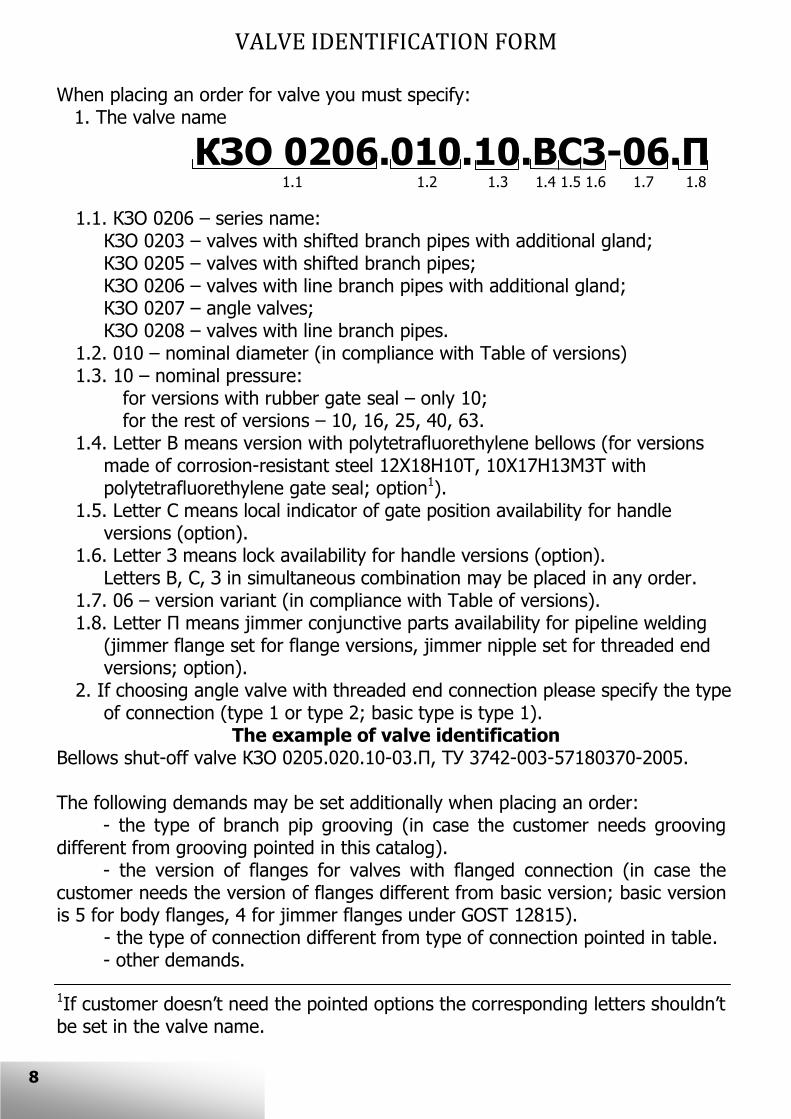
When placing an order for valve you must specify: 1. The valve name
КЗО 0206.010.10.ВСЗ-06.П
1.1 1.2 1.3 1.4 1.5 1.6 1.7 1.8
1.1. КЗО 0206 – series name: КЗО 0203 – valves with shifted branch pipes with additional gland; КЗО 0205 – valves with shifted branch pipes; КЗО 0206 – valves with line branch pipes with additional gland; КЗО 0207 – angle valves; КЗО 0208 – valves with line branch pipes.
1.2. 010 – nominal diameter (in compliance with Table of versions) 1.3. 10 – nominal pressure:
for versions with rubber gate seal – only 10; for the rest of versions – 10, 16, 25, 40, 63.
1.4. Letter В means version with polytetrafluorethylene bellows (for versions made of corrosion-resistant steel 12Х18Н10Т, 10Х17Н13М3Т with polytetrafluorethylene gate seal; option1).
1.5. Letter С means local indicator of gate position availability for handle versions (option).
1.6. Letter З means lock availability for handle versions (option). Letters В, С, З in simultaneous combination may be placed in any order. 1.7. 06 – version variant (in compliance with Table of versions). 1.8. Letter П means jimmer conjunctive parts availability for pipeline welding
(jimmer flange set for flange versions, jimmer nipple set for threaded end versions; option).
2. If choosing angle valve with threaded end connection please specify the type of connection (type 1 or type 2; basic type is type 1).
The example of valve identification Bellows shut-off valve КЗО 0205.020.10-03.П, ТУ 3742-003-57180370-2005. The following demands may be set additionally when placing an order: - the type of branch pip grooving (in case the customer needs grooving different from grooving pointed in this catalog). - the version of flanges for valves with flanged connection (in case the customer needs the version of flanges different from basic version; basic version is 5 for body flanges, 4 for jimmer flanges under GOST 12815). - the type of connection different from type of connection pointed in table. - other demands.
1If customer doesn’t need the pointed options the corresponding letters shouldn’t be set in the valve name.
8

VALVE ARRANGEMENT (SERIES КЗО 0205 AS AN EXAMPLE)
8
7
6
5
4
3
2
1
9

A material of main parts
Pos. Name
Material
For
vers
ions
made o
f
steel 12Х18Н
10Т
For
vers
ions
made o
f
steel 20
For
vers
ions
made o
f
steel 09Г2С
For
vers
ions
made o
f
steel 10Х17Н
13М
3Т
1 Body 12Х18Н10Т Steel 20 09Г2С 10Х17Н13М3Т
(10Х17Н13М2Т)
2 Spool 12Х18Н10Т Steel 20 12Х18Н10Т 10Х17Н13М3Т
(10Х17Н13М2Т)
Bellows junction
3 Bellows 12Х18Н10Т
or Ф-41 12Х18Н10Т
10Х17Н13М3Т (10Х17Н13М2Т)
or Ф-41
5 Ring 12Х18Н10Т 10Х17Н13М3Т
(10Х17Н13М2Т)
4 Spindle 12Х18Н10Т 10Х17Н13М3Т
(10Х17Н13М2Т)
6 Cover 12Х18Н10Т or steel 20
Steel 20 09Г2С 12Х18Н10Т or steel 20
7 Bush БрАЖН 10-4-4
1Ф-4 is the mark of polytetrafluorethylene.
10

TABLE OF VERSIONS
DN
Nam
e
Contr
ol
Pip
elin
e c
onnect
ion
Est
imate
d
tem
pera
ture
Gate
seal
“Body-c
over”
seal A material of main parts
12Х18Н
10Т
10Х17Н
13М
3Т
Ste
el 20
09Г2С
3
КЗО
0208.0
03.1
0
handle
threaded
end 50 rubber rubber -10 -31 -52 -73
DN
Nam
e
Contr
ol
Pip
elin
e c
onnect
ion
Est
imate
d
tem
pera
ture
Gate
seal
“Body-c
over”
seal A material of main parts
12Х18Н
10Т
10Х17Н
13М
3Т
Ste
el 20
09Г2С
6
КЗО
0203.0
06.Y
Y
КЗО
0205.0
06.Y
Y
КЗО
0206.0
06.Y
Y
КЗО
0207.0
06.Y
Y
КЗО
0208.0
06.Y
Y
handle
welding 350 ЦН-12М st-st1 -06 -27 -48 -69
threaded end
350 ЦН-12М
paronite -100 -121 -142 -163
350 st-st1 -103 -124 -145 -166
200 Ф-4 Ф-4 -109 -130 -151 -172
50 rubber rubber -112 -133 -153 -174
-102 -312 -522 -732
КЗО 0203 – valves with shifted branch pipes and additional gland; КЗО 0205 – valves with shifted branch pipes; КЗО 0206 – valves with line branch pipes and additional gland; КЗО 0207 – angle valves; КЗО 0208 – valves with line branch pipes. YY – nominal pressure (10, 16, 25, 40, 63). “St-st” is shortening of «steel to steel» Valves with rubber gate seal are employed only at pressure up to 1,0 MPa. 1For versions at PN63 paronite is used as “body-cover” seal. 2Versions -10, -31, -52, -73 are used only for series КЗО 0208 and only for PN10.
11

12
TABLE OF VERSIONS (CONTINUE)
DN
Nam
e
Contr
ol
Pip
elin
e c
onnect
ion
Est
imate
d
tem
pera
ture
Gate
seal
“Body-c
over”
seal A material of main parts
12Х18Н
10Т
10Х17Н
13М
3Т
Ste
el 20
09Г2С
10 15 20 25
КЗО
0203.0
ХХ.Y
Y
КЗО
0205.0
ХХ.Y
Y
КЗО
0206.0
ХХ.Y
Y
КЗО
0207.0
ХХ.Y
Y
КЗО
0208.0
ХХ.Y
Y
handle
flanged
350 ЦН-12М
paronite -00 -21 -42 -63
350 st-st1 -03 -24 -45 -66
200 Ф-4 Ф-4 -09 -30 -51 -72
50 rubber rubber -12 -33 -53 -74
welding 350 ЦН-12М st-st1 -06 -27 -48 -69
threaded end
350 ЦН-12М
paronite -100 -121 -142 -163
350 st-st1 -103 -124 -145 -166
200 Ф-4 Ф-4 -109 -130 -151 -172
50 rubber rubber -112 -133 -153 -174
-102 -312 -522 -732
art
icula
ted c
ouplin
g
flanged
350 ЦН-12М
paronite -01 -22 -43 -64
350 st-st1 -04 -25 -46 -67
200 Ф-4 Ф-4 -13 -34 -54 -75
50 rubber rubber -16 -37 -56 -77
welding 350 ЦН-12М st-st1 -07 -28 -49 -70
threaded end
350 ЦН-12М
paronite -101 -122 -143 -164
350 st-st1 -104 -125 -146 -167
200 Ф-4 Ф-4 -113 -134 -154 -175
50 rubber rubber -116 -137 -156 -177
ele
ctric
drive flanged
350 ЦН-12М
paronite -02 -23 -44 -65
350 st-st1 -05 -26 -47 -68
200 Ф-4 Ф-4 -17 -38 -57 -78
50 rubber rubber -20 -41 -59 -80
welding 350 ЦН-12М st-st1 -08 -29 -50 -71
threaded end
350 ЦН-12М
paronite -102 -123 -144 -165
350 st-st1 -105 -126 -147 -168
200 Ф-4 Ф-4 -117 -138 -157 -178
50 rubber rubber -120 -141 -159 -180
КЗО 0203 – valves with shifted branch pipes and additional gland; КЗО 0205 – valves with shifted branch pipes; КЗО 0206 – valves with line branch pipes and additional gland; КЗО 0207 – angle valves; КЗО 0208 – valves with line branch pipes. ХХ – nominal diameter (10, 15, 20, 25) YY – nominal pressure (10, 16, 25, 40, 63). “St-st” is shortening of «steel to steel» Valves with rubber gate seal are employed only at pressure up to 1,0 MPa. 1For versions at PN63 paronite is used as “body-cover” seal. 2Versions -10, -31, -52, -73 are used only for series КЗО 0208 and only for PN10.

TABLE OF VERSIONS (CONTINUE)
DN
Nam
e
Contr
ol
Pip
elin
e c
onnect
ion
Est
imate
d
tem
pera
ture
Gate
seal
“Body-c
over”
seal A material of main parts
12Х18Н
10Т
10Х17Н
13М
3Т
Ste
el 20
09Г2С
32 40 50 65 80 100 125 150 К
ЗО
0203.Х
ХХ.Y
Y
КЗО
0205.Х
ХХ.Y
Y
КЗО
0206.Х
ХХ.Y
Y
КЗО
0207.Х
ХХ.Y
Y
КЗО
0208.Х
ХХ.Y
Y
handle
flanged
350 ЦН-12М
paronite -00 -21 -42 -63
350 st-st1 -03 -24 -45 -66
200 Ф-4 Ф-4 -09 -30 -51 -72
50 rubber rubber -12 -33 -53 -74
welding 350 ЦН-12М st-st1 -06 -27 -48 -69
art
icula
ted
couplin
g
flanged
350 ЦН-12М
paronite -01 -22 -43 -64
350 st-st1 -04 -25 -46 -67
200 Ф-4 Ф-4 -13 -34 -54 -75
50 rubber rubber -16 -37 -56 -77
welding 350 ЦН-12М st-st1 -07 -28 -49 -70
ele
ctric
drive
flanged
350 ЦН-12М
paronite -02 -23 -44 -65
350 st-st1 -05 -26 -47 -68
200 Ф-4 Ф-4 -17 -38 -57 -78
50 rubber rubber -20 -41 -59 -80
welding 350 ЦН-12М st-st1 -08 -29 -50 -71
КЗО 0203 – valves with shifted branch pipes and additional gland; КЗО 0205 – valves with shifted branch pipes; КЗО 0206 – valves with line branch pipes and additional gland; КЗО 0207 – angle valves; КЗО 0208 – valves with line branch pipes. ХХХ – Nominal diameter (032, 040, 050, 065, 080, 100, 125, 150) YY – Nominal pressure (10, 16, 25, 40, 63). “St-st” is shortening of «steel to steel» Valves with rubber gate seal are employed only at pressure up to 1,0 MPa. 1For versions at PN63 paronite is used as “body-cover” seal.
13

14
Electric drives table
DN Number
of turns Parameter
Pp, MPa
1,0 1,6 2,5 4,0 6,3
10 15
2±0,5
Pr, Н×m 8±2 (5*) 8±2 15±2 20±2 23±2
E.drive
(operating time,
seconds)
Н-М-01 (12±1) Н-М-01 (12±1) Н-М-03 (12±1) Н-М-03 (12±1) Н-М-03 (12±1)
20 25
3±0,5
Pr, Н×m 15±2 (10*) *** 20±2 *** 23±2 *** 25±3 40±3
E.drive (operating
time, seconds)
Н-М-03 (24±2) ** ЭП4 Н-А-60-90 (2,5±0,5)
ПЭМ-А0-У2 (8±1)
Н-М-03 (24±2) ** ЭП4 Н-А-60-90 (2,5±0,5)
ПЭМ-А0-У2 (8±1)
Н-М-03 (24±2) ** ЭП4 Н-А-60-90 (2,5±0,5)
ПЭМ-А0-У2 (8±1)
Н-М-03 (24±1) ** ЭП4 Н-А-60-90 (2,5±0,5)
ПЭМ-А0-У2 (8±1)
Н-А2-01 (15±1) ** Н-А2-02 (8±1)
ЭП4 Н-А-60-90 (2,5±0,5) ПЭМ-А0-У2 (8±1)
32 3±0,5
Pr, Н×m 30±3 (25*) 30±3 35±3 40±3 50±3
E.drive
(operating
time, seconds)
Н-А2-01 (18±2) ** Н-А2-02 (9±1)
ЭП4 Н-А-60-90 (2,5±0,5)
ЭП4 Н-А-60-125 (1,6±0,5) ЭП4 Н-А-60-180 (1,3±0,5)
ПЭМ-А1-У2 (8±1)
Н-А2-01 (18±2) ** Н-А2-02 (9±1)
ЭП4 Н-А-60-90 (2,5±0,5)
ЭП4 Н-А-60-125 (1,6±0,5) ЭП4 Н-А-60-180 (1,3±0,5)
ПЭМ-А1-У2 (8±1)
Н-А2-01 (18±2) ** Н-А2-02 (9±1)
ЭП4 Н-А-60-90 (2,5±0,5)
ЭП4 Н-А-60-125 (1,6±0,5) ЭП4 Н-А-60-180 (1,3±0,5)
ПЭМ-А1-У2 (8±1)
Н-А2-01 (18±2) ** Н-А2-02 (9±1)
ЭП4 Н-А-60-90 (2,5±0,5)
ЭП4 Н-А-60-125 (1,6±0,5) ЭП4 Н-А-60-180 (1,3±0,5)
ПЭМ-А1-У2 (8±1)
Н-А2-07 (18±2) ** Н-А2-08 (9±1)
ЭП4 Н-А-60-90 (2,5±0,5)
ЭП4 Н-А-60-125 (1,6±0,5) ЭП4 Н-А-60-180 (1,3±0,5)
ПЭМ-А1-У2 (8±1)
40 3±0,5
Pr, Н×m 30±3 (25*) 35±3 45±3 55±3 70±5
E.drive (operating
time,
seconds)
Н-А2-01 (18±2) **
Н-А2-02 (9±1) ЭП4 Н-А-60-90 (2,5±0,5)
ЭП4 Н-А-60-125 (1,6±0,5)
ЭП4 Н-А-60-180 (1,3±0,5) ПЭМ-А1-У2 (8±1)
Н-А2-01 (18±2) **
Н-А2-02 (9±1) ЭП4 Н-А-60-90 (2,5±0,5)
ЭП4 Н-А-60-125 (1,6±0,5)
ЭП4 Н-А-60-180 (1,3±0,5) ПЭМ-А1-У2 (8±1)
Н-А2-01 (18±2) **
Н-А2-02 (9±1) ЭП4 Н-А-60-90 (2,5±0,5)
ЭП4 Н-А-60-125 (1,6±0,5)
ЭП4 Н-А-60-180 (1,3±0,5) ПЭМ-А1-У2 (8±1)
Н-А2-01 (18±2) **
Н-А2-02 (9±1) ЭП4 Н-А-120-90 (2,5±0,5)
ЭП4 Н-А-120-125 (1,6±0,5)
ЭП4 Н-А-90-180 (1,3±0,5) ПЭМ-А1-У2 (8±1)
Н-А2-07 (18±2) **
Н-А2-08 (9±1) ЭП4 Н-А-120-90 (2,5±0,5)
ЭП4 Н-А-120-125 (1,6±0,5)
ЭП4 Н-А-90-180 (1,3±0,5) ПЭМ-А1-У2 (8±1)
50 3±0,5
Pr, Н×m 35±3 (25*) 40±3 55±3 60±5 90±5
E.drive
(operating time,
seconds)
Н-А2-01 (18±2) ** Н-А2-02 (9±1)
ЭП4 Н-А-60-90 (2,5±0,5) ЭП4 Н-А-60-125 (1,6±0,5)
ЭП4 Н-А-60-180 (1,3±0,5)
ПЭМ-А1-У2 (8±1)
Н-А2-01 (18±2) ** Н-А2-02 (9±1)
ЭП4 Н-А-60-90 (2,5±0,5) ЭП4 Н-А-60-125 (1,6±0,5)
ЭП4 Н-А-60-180 (1,3±0,5)
ПЭМ-А1-У2 (8±1)
Н-А2-01 (18±2) ** Н-А2-02 (9±1)
ЭП4 Н-А-60-90 (2,5±0,5) ЭП4 Н-А-60-125 (1,6±0,5)
ЭП4 Н-А-60-180 (1,3±0,5)
ПЭМ-А1-У2 (8±1)
Н-А2-01 (18±2) ** Н-А2-02 (9±1)
ЭП4 Н-А-120-90 (2,5±0,5) ЭП4 Н-А-120-125 (1,6±0,5)
ЭП4 Н-А-90-180 (1,3±0,5)
ПЭМ-А9-У2 (8±1)
Н-А2-07 (18±2) ** Н-А2-08 (9±1)
ЭП4 Н-А-120-90 (2,5±0,5) ЭП4 Н-А-120-125 (1,6±0,5)
ЭП4 Н-А-90-180 (1,3±0,5)
ПЭМ-А9-У2 (8±1)
65 4±1
Pr, Н×m 60±3 65±3 80±5 90±5 110±5
E.drive
(operating time,
seconds)
Н-А2-07 (23±2) **
Н-А2-08 (12±1)
ЭП4 Н-А-120-90 (2,7±0,5) ЭП4 Н-А-120-125 (2,0±0,5)
ЭП4 Н-А-90-180 (1,4±0,5) ПЭМ-А9-У2 (10±1)
Н-А2-07 (23±2) **
Н-А2-08 (12±1)
ЭП4 Н-А-120-90 (2,7±0,5) ЭП4 Н-А-120-125 (2,0±0,5)
ЭП4 Н-А-90-180 (1,4±0,5) ПЭМ-А9-У2 (10±1)
Н-А2-07 (23±2) **
Н-А2-08 (12±1)
ЭП4 Н-А-120-90 (2,7±0,5) ЭП4 Н-А-120-125 (2,0±0,5)
ЭП4 Н-А-90-180 (1,4±0,5) ПЭМ-А9-У2 (10±1)
Н-А2-07 (23±2) **
Н-А2-08 (12±1)
ЭП4 Н-А-120-90 (2,7±0,5) ЭП4 Н-А-120-125 (2,0±0,5)
ЭП4 Н-А-90-180 (1,4±0,5) ПЭМ-А9-У2 (10±1)
Н-Б1-01 (11±1) **
Н-Б1-04 (6±1) ЭП4 Н-Б-250-90 (2,7±0,5)
ЭП4 Н-Б-250-125 (2,0±0,5) ЭП4 Н-Б-250-180 (1,4±0,5)
ПЭМ-Б1-У2 (10±1)
ПЭМ-Б4-У2 (5±1)

15
Electric drives (continue)
DN Number of turns
Parameter Pp, MPa
1,0 1,6 2,5 4,0 6,3
80 4±1
Pr, Н×m 70±5 (60*) 75±5 90±5 100±5 140±10
E.drive
(operating time,
seconds)
Н-А2-07 (23±2) ** Н-А2-08 (12±1)
ЭП4 Н-А-120-90 (2,7±0,5) ЭП4 Н-А-120-125 (2,0±0,5)
ЭП4 Н-А-90-180 (1,4±0,5)
ПЭМ-А9-У2 (10±1)
Н-А2-07 (23±2) ** Н-А2-08 (12±1)
ЭП4 Н-А-120-90 (2,7±0,5) ЭП4 Н-А-120-125 (2,0±0,5)
ЭП4 Н-А-90-180 (1,4±0,5)
ПЭМ-А9-У2 (10±1)
Н-А2-07 (23±2) ** Н-А2-08 (12±1)
ЭП4 Н-А-120-90 (2,7±0,5) ЭП4 Н-А-120-125 (2,0±0,5)
ЭП4 Н-А-90-180 (1,4±0,5)
ПЭМ-А9-У2 (10±1)
Н-А2-07 (23±2) ** Н-А2-08 (12±1)
ЭП4 Н-А-120-90 (2,7±0,5) ЭП4 Н-А-120-125 (2,0±0,5)
ЭП4 Н-А-90-180 (1,4±0,5)
ПЭМ-А9-У2 (10±1)
Н-Б1-01 (11±1) **
Н-Б1-04 (6±1) ЭП4 Н-Б-250-90 (2,7±0,5)
ЭП4 Н-Б-250-125 (2,0±0,5)
ЭП4 Н-Б-250-180 (1,4±0,5) ПЭМ-Б1-У2 (10±1)
ПЭМ-Б4-У2 (5±1)
100 5±1
Pr, Н×m 100±5 110±5 140±10 160±10 190±10
E.drive
(operating time,
seconds)
Н-Б1-01 (13±1) **
Н-Б1-04 (7±1) ЭП4 Н-Б-250-90 (3,4±0,5)
ЭП4 Н-Б-250-125 (2,5±0,5)
ЭП4 Н-Б-250-180 (1,7±0,5) ПЭМ-Б1-У2 (12±1)
ПЭМ-Б4-У2 (6±1)
Н-Б1-01 (13±1) **
Н-Б1-04 (7±1) ЭП4 Н-Б-250-90 (3,4±0,5)
ЭП4 Н-Б-250-125 (2,5±0,5)
ЭП4 Н-Б-250-180 (1,7±0,5) ПЭМ-Б1-У2 (12±1)
ПЭМ-Б4-У2 (6±1)
Н-Б1-01 (13±1) **
Н-Б1-04 (7±1) ЭП4 Н-Б-250-90 (3,4±0,5)
ЭП4 Н-Б-250-125 (2,5±0,5)
ЭП4 Н-Б-250-180 (1,7±0,5) ПЭМ-Б1-У2 (12±1)
ПЭМ-Б4-У2 (6±1)
Н-Б1-01 (13±1) **
Н-Б1-04 (7±1) ЭП4 Н-Б-250-90 (3,4±0,5)
ЭП4 Н-Б-250-125 (2,5±0,5)
ЭП4 Н-Б-250-180 (1,7±0,5) ПЭМ-Б1-У2 (12±1)
ПЭМ-Б4-У2 (6±1)
Н-Б1-01 (13±1) **
Н-Б1-04 (7±1) ЭП4 Н-Б-250-90 (3,4±0,5)
ЭП4 Н-Б-250-125 (2,5±0,5)
ЭП4 Н-Б-250-180 (1,7±0,5) ПЭМ-Б1-У2 (12±1)
ПЭМ-Б4-У2 (6±1)
125 6±1
Pr, Н×m 250±10 250±10 280±10 320±10 350±10
E.drive (operating
time, seconds)
Н-В-02 (15±2) **
Н-В-05 (8±1)
ЭП4 Н-Б-500-90 (4,5±0,5) ЭП4 Н-Б-400-180 (2,5±0,5)
ПЭМ В02 630 24 36 М-IP67 (15±2)
ПЭМ В10 630 48 36 М-IP67 (8±2)
Н-В-02 (15±2) **
Н-В-05 (8±1)
ЭП4 Н-Б-500-90 (4,5±0,5) ЭП4 Н-Б-400-180 (2,5±0,5)
ПЭМ В02 630 24 36 М-IP67 (15±2)
ПЭМ В10 630 48 36 М-IP67 (8±2)
Н-В-02 (15±2) **
Н-В-05 (8±1)
ЭП4 Н-Б-500-90 (4,5±0,5) ЭП4 Н-Б-400-180 (2,5±0,5)
ПЭМ В02 630 24 36 М-IP67 (15±2)
ПЭМ В10 630 48 36 М-IP67 (8±2)
Н-В-02 (15±2) **
Н-В-05 (8±1)
ЭП4 Н-Б-500-90 (4,5±0,5) ЭП4 Н-Б-400-180 (2,5±0,5)
ПЭМ В02 630 24 36 М-IP67 (15±2)
ПЭМ В10 630 48 36 М-IP67 (8±2)
Н-В-02 (15±2) **
Н-В-05 (8±1)
ЭП4 Н-Б-500-90 (4,5±0,5) ЭП4 Н-Б-400-180 (2,5±0,5)
ПЭМ В02 630 24 36 М-IP67 (15±2)
ПЭМ В10 630 48 36 М-IP67 (8±2)
150 6±1
Pr, Н×m 250±10 260±10 300±20 350±20 400±20
E.drive
(operating time,
seconds)
Н-В-02 (15±2) **
Н-В-05 (8±1) ЭП4 Н-Б-500-90 (4,5±0,5)
ЭП4 Н-Б-400-180 (2,5±0,5) ПЭМ В02 630 24 36 М-IP67
(15±2) ПЭМ В10 630 48 36 М-IP67
(8±2)
Н-В-02 (15±2) **
Н-В-05 (8±1) ЭП4 Н-Б-500-90 (4,5±0,5)
ЭП4 Н-Б-400-180 (2,5±0,5) ПЭМ В02 630 24 36 М-IP67
(15±2) ПЭМ В10 630 48 36 М-IP67
(8±2)
Н-В-02 (15±2) **
Н-В-05 (8±1) ЭП4 Н-Б-500-90 (4,5±0,5)
ЭП4 Н-Б-400-180 (2,5±0,5) ПЭМ В02 630 24 36 М-IP67
(15±2) ПЭМ В10 630 48 36 М-IP67
(8±2)
Н-В-02 (15±2) **
Н-В-05 (8±1) ЭП4 Н-Б-500-90 (4,5±0,5)
ЭП4 Н-Б-400-180 (2,5±0,5) ПЭМ В02 630 24 36 М-IP67
(15±2) ПЭМ В10 630 48 36 М-IP67
(8±2)
Н-В-02 (15±2) **
Н-В-05 (8±1) ЭП4 Н-Б-500-90 (4,5±0,5)
ЭП4 Н-Б-400-180 (2,5±0,5) ПЭМ В02 630 24 36 М-IP67
(15±2) ПЭМ В10 630 48 36 М-IP67
(8±2)
“Pr” means rotating power. * Rotating power indicated for valves with rubber gate seal.
** Basic electric drive.
Output spindle: DN 10…50 – square, DN 65…150 – cam dog.

16
DRAWINGS VALVES WITH SHIFTED BRANCH PIPES КЗО 0205
DN6…15 Pp 1,0…1,6 MPa DN10, 15 Pp 1,0…1,6 MPa
DN6…15 Pp 2,5…6,3 MPa DN10, 15 Pp 2,5…6,3 MPa
DN20, 25

DN100…150
DN65, 80
DN32…50
17
18
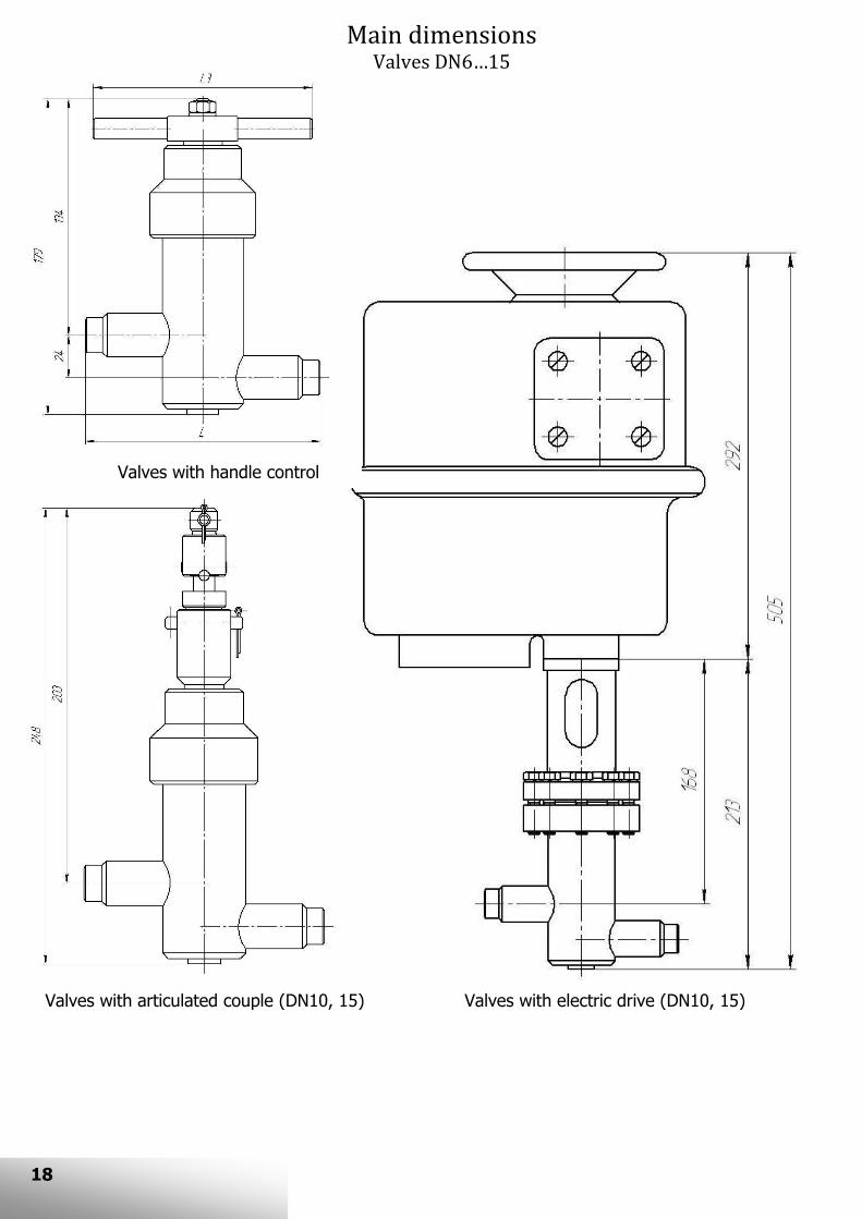
Main dimensions Valves DN6…15
Valves with handle control
Valves with electric drive (DN10, 15) Valves with articulated couple (DN10, 15)
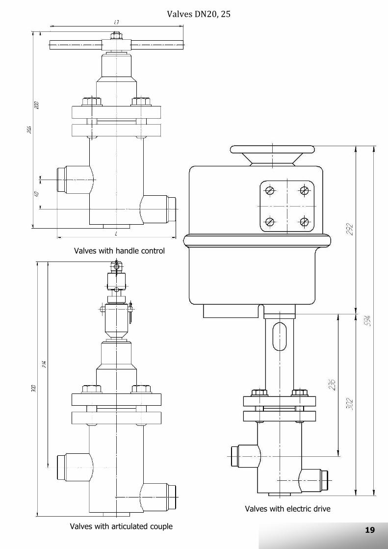
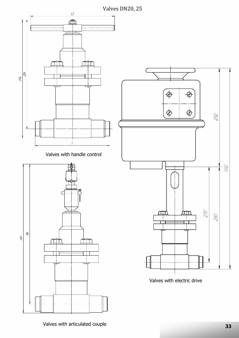
Valves DN20, 25
Valves with handle control
Valves with electric drive
Valves with articulated couple 19

20
Valves DN32…150
Valves with handle control
Valves DN32…80 with electric drive
Valves with articulated couple
Valves DN100…150 with electric drive

Dimensions table DN 6…15
DN L L3
Pр 1,0…4,0 MPa Pр 6,3 MPa Pр 1,0…4,0 MPa Рр 6,3 MPa
6 100 100 80 125
10 130 160 100 170
15 130 175 125 170
DN 20, 25
DN L L3
Pр 1,0…4,0 MPa Pр 6,3 MPa Pр 1,0…1,6 MPa Pр 2,5…6,3 MPa
20 150 190 180 240
25 160 200 180 240
DN 32…150
DN
L
H
L1
H1 H2 H3 H4 H5 H6 H7 Н8 Pр
1,0…4,0
MPa
Pр
6,3
MPa
Pр
1,0…1,6
MPa
Pр
2,5…6,3
MPa
32 180 210 45
200 330
200 276 268 344 304 380 880 -
40 200 225 55 194 282 282 370 298 386 886 -
50 230 300 65 194 300 282 388 298 404 904 -
65 290 340 84 260 500
218 350 298 430 326 458 958 -
80 310 380 95 220 373 298 451 329 482 982 -
100 350 430 120
385 485
240 426 415 601 350 536 976 440
125 400 500 150 294 537 430 673 387 630 1150 520
150 480 550 176 294 564 446 716 387 657 1177
21

22
VALVES WITH SHIFTED BRANCH PIPES AND ADDITIONAL GLAND КЗО 0203
DN6…15
DN20, 25
DN10…15

23
DN100…150
DN65, 80
DN32…50

24
Main dimensions Valves DN6…15
Valves with handle control
Valves with electric drive (DN10, 15)
Valves with articulated couple (DN10, 15)

25
Valves DN20, 25
Valves with handle control
Valves with electric drive
Valves with articulated couple

26
Valves DN32…150
Valves with handle control
Valves DN32…80 with electric drive
Valves with articulated couple
Valves DN100…150 with electric drive

27
Dimensions table DN 6…15
DN L L3
Pр 1,0…4,0 MPa Pр 6,3 MPa Pр 1,0…4,0 MPa Рр 6,3 MPa
6 100 100 80 125
10 130 160 100 170
15 130 175 125 170
DN 20, 25
DN L L3
Pр 1,0…4,0 MPa Pр 6,3 MPa Pр 1,0…1,6 MPa Pр 2,5…6,3 MPa
20 150 190 180 240
25 160 200 180 240
DN 32…150
DN
L
H
L3
H1 H2 H3 H4 H5 H6 H7 Н8 Pр
1,0…4,0
MPa
Pр
6,3
MPa
Pр
1,0…1,6
MPa
Pр
2,5…6,3
MPa
32 180 210 45
200 330
254 324 332 402 353 423 923 -
40 200 225 55 260 343 343 425 360 442 942 -
50 230 300 65 260 356 343 438 360 455 955 -
65 290 340 84 260 500
294 423 374 503 402 531 1031 -
80 310 380 95 307 457 385 535 416 566 1066 -
100 350 430 120
385 485
330 515 505 690 440 625 1065 440
125 400 500 150 375 600 527 752 468 693 1213 520
150 480 550 176 375 640 527 792 468 733 1253
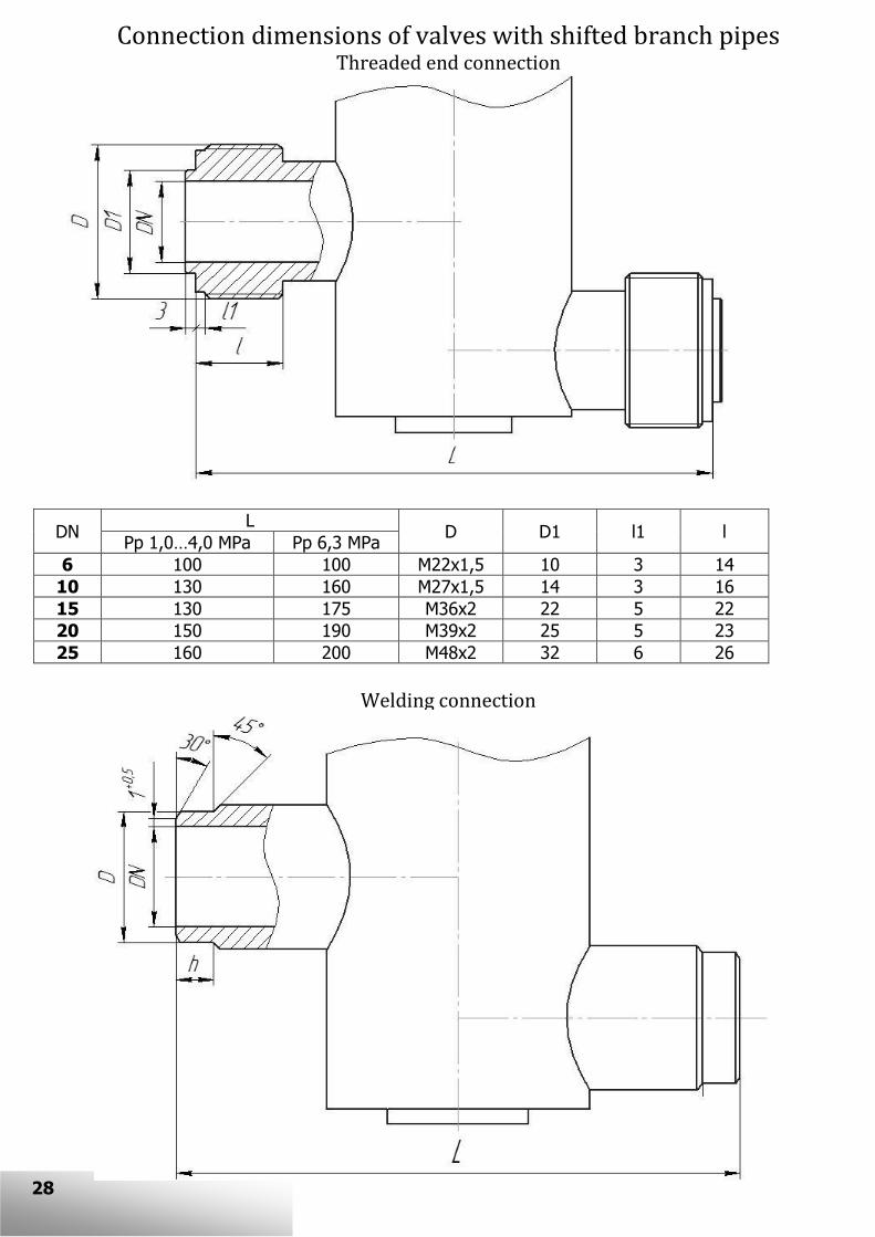
28
Connection dimensions of valves with shifted branch pipes Threaded end connection
DN L
D D1 l1 l Pp 1,0…4,0 MPa Pp 6,3 MPa
6 100 100 М22х1,5 10 3 14
10 130 160 М27х1,5 14 3 16
15 130 175 М36х2 22 5 22
20 150 190 М39х2 25 5 23
25 160 200 М48х2 32 6 26
Welding connection

29
DN L
D h Pp 1,0…4,0 MPa Pp 6,3 MPa
6 100 100 11 8
10 130 160 15 10
15 130 175 20 10
20 150 190 27 10
25 160 200 32 10
32 180 210 37 12
40 200 225 47 12
50 230 300 57 12
65 290 340 67 15
80 310 380 82 15
100 350 430 102 25
125 400 500 127 25
150 480 550 154 25
Flanged connection
DN D D1 D2
D3 D4 b*
h h1
d n
1) 2) 3) 1) 2) 3) 1,0
MPa
1,6
MPa
2,5
MPa
4,0
MPa
6,3
MPa 1) 2) 3)
1,0;
1,6 MPa
2,5…
6,3 MPa
10 23 35 42 60 70 90 100 10 12 14 16
2 3 14
4
15 28 40 47 65 75 95 105 2 3 14
20 35 51 58 75 90 105 125 12 14 16 14 18 2 3 14 18
25 42 58 68 85 100 115 135 12 16 14 20 2 3 14 18
32 50 66 78 100 110 135 150 14 16 18 16 21 2 3 18 22
40 60 76 88 110 125 145 165 15 17 19 16 21 3 3 18 22
50 72 88 102 125 135 160 175 15 19 21 17 23 3 3 18 22
65 94 110 122 145 160 180 200 17 21 19 25 3 3 18 22 4 8
80 105 121 133 160 170 195 210 17 21 23 21 27 3 3 18 22 4 8
100 128 150 158 180 190 200 215 230 250 19 23 25 23 29 3 3 18 22 26
8 125 154 176 184 210 220 240 245 270 295 21 25 27 25 33 3 3 18 26 30
150 182 204 212 240 250 280 280 300 340 21 25 27 35 3 3 22 26 33
1) Рр 1,0; 1,6 MPa
2) Рр 2,5; 4,0 MPa
3) Рр 6,3 MPa
* For information

30
VALVES WITH LINE BRANCH PIPES КЗО 0208 ALL VERSIONS EXCEPT -10, -31, -52, -73
DN6…15 Pp 1,0…1,6 MPa DN10, 15 Pp 1,0…1,6 MPa
DN6…15 Pp 2,5…6,3 MPa DN10, 15 Pp 2,5…6,3 MPa
DN20, 25

31
DN100…150
DN65, 80
DN32…50

32
Main dimensions Valves DN6…15
Valves with handle control
Valves with electric drive (DN10, 15)
Valves with articulated couple (DN10, 15)
33
Valves DN20, 25
Valves with handle control
Valves with electric drive
Valves with articulated couple

34
Valves DN32…150
Valves with handle control
Valves DN32…80 with electric drive
Valves with articulated couple
Valves DN100…150 with electric drive

35
Dimensions table DN 6…15
DN L L3
Pр 1,0…4,0 MPa Pр 6,3 MPa Pр 1,0…4,0 MPa Рр 6,3 MPa
6 100 100 80 125
10 130 160 100 170
15 130 175 125 170
DN 20, 25
DN L L3
Pр 1,0…4,0 MPa Pр 6,3 MPa Pр 1,0…1,6 MPa Pр 2,5…6,3 MPa
20 150 190 180 240
25 160 200 180 240
DN 32…150
DN
L L3
H1 H2 H3 H4 H5 H6 H7 Н8 Pр
1,0…4,0
MPa
Pр
6,3
MPa
Pр
1,0…1,6
MPa
Pр
2,5…6,3
MPa
32 180 210
200 330
241 266 309 334 345 370 870 -
40 200 225 245 272 333 360 349 376 876 -
50 230 300 260 295 342 377 358 393 893 -
65 290 340 260 500
303 348 383 428 411 456 956 -
80 310 380 322 377 400 455 431 486 986 -
100 350 430
385 485
360 425 535 600 470 535 975 440
125 400 500 450 525 586 661 543 618 1138 520
150 480 550 475 565 627 717 568 658 1178

DN15, 20 DN3, 6, 10
36
VACUUM VALVES (КЗО 0208 VERSIONS -10, -31, -52, -73)

37
Dimensions table
DN Dimensions
Mass, kg L L1 H1 d3
3 55 65 156 8 2
6 66 92 156 12 2
10 66 92 156 16 2
15 106 144 225 26 3,5
20 106 144 225 30 3,5
38
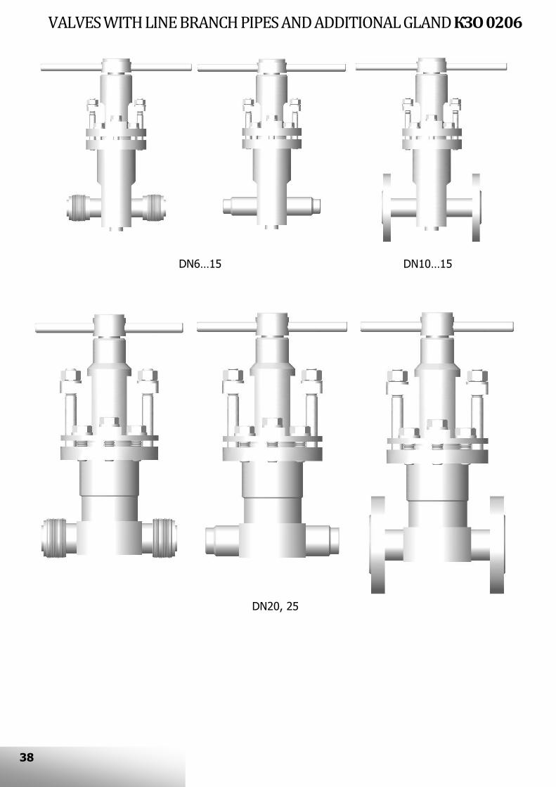
VALVES WITH LINE BRANCH PIPES AND ADDITIONAL GLAND КЗО 0206
DN6…15
DN20, 25
DN10…15

39
DN100…150
DN65, 80
DN32…50

40
Main dimensions Valves DN6…15
Valves with handle control
Valves with electric drive (DN10, 15)
Valves with articulated couple (DN10, 15)

41
Valves DN20, 25
Valves with handle control
Valves with electric drive
Valves with articulated couple

42
Valves DN32…150
Valves with handle control
Valves DN32…80 with electric drive
Valves with articulated couple
Valves DN100…150 with electric drive
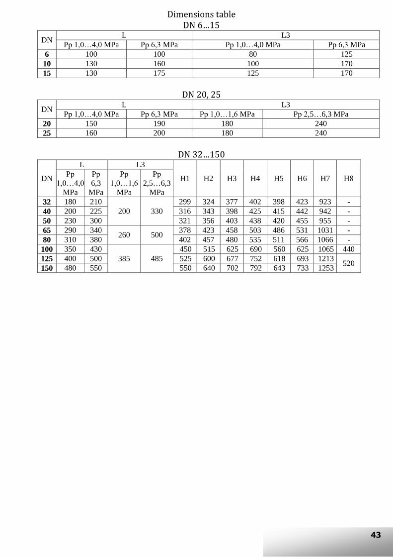
43
Dimensions table DN 6…15
DN L L3
Pр 1,0…4,0 MPa Pр 6,3 MPa Pр 1,0…4,0 MPa Рр 6,3 MPa
6 100 100 80 125
10 130 160 100 170
15 130 175 125 170
DN 20, 25
DN L L3
Pр 1,0…4,0 MPa Pр 6,3 MPa Pр 1,0…1,6 MPa Pр 2,5…6,3 MPa
20 150 190 180 240
25 160 200 180 240
DN 32…150
DN
L L3
H1 H2 H3 H4 H5 H6 H7 Н8 Pр
1,0…4,0
MPa
Pр
6,3
MPa
Pр
1,0…1,6
MPa
Pр
2,5…6,3
MPa
32 180 210
200 330
299 324 377 402 398 423 923 -
40 200 225 316 343 398 425 415 442 942 -
50 230 300 321 356 403 438 420 455 955 -
65 290 340 260 500
378 423 458 503 486 531 1031 -
80 310 380 402 457 480 535 511 566 1066 -
100 350 430
385 485
450 515 625 690 560 625 1065 440
125 400 500 525 600 677 752 618 693 1213 520
150 480 550 550 640 702 792 643 733 1253

44
Connection dimensions of valves with line branch pipes Threaded end connection
DN L
D D1 l1 l Pp 1,0…4,0 MPa Pp 6,3 MPa
6 100 100 М22х1,5 10 3 14
10 130 160 М27х1,5 14 3 16
15 130 175 М36х2 22 5 22
20 150 190 М39х2 25 5 23
25 160 200 М48х2 32 6 26
Welding connection

45
DN L
D h Pp 1,0…4,0 MPa Pp 6,3 MPa
6 100 100 11 8
10 130 160 15 10
15 130 175 20 10
20 150 190 27 10
25 160 200 32 10
32 180 210 37 12
40 200 225 47 12
50 230 300 57 12
65 290 340 67 15
80 310 380 82 15
100 350 430 102 25
125 400 500 127 25
150 480 550 154 25
Flanged connection
DN D D1 D2
D3 D4 b*
h h1
d n
1) 2) 3) 1) 2) 3) 1,0
MPa
1,6
MPa
2,5
MPa
4,0
MPa
6,3
MPa 1) 2) 3)
1,0;
1,6 MPa
2,5…
6,3 MPa
10 23 35 42 60 70 90 100 10 12 14 16
2 3 14
4
15 28 40 47 65 75 95 105 2 3 14
20 35 51 58 75 90 105 125 12 14 16 14 18 2 3 14 18
25 42 58 68 85 100 115 135 12 16 14 20 2 3 14 18
32 50 66 78 100 110 135 150 14 16 18 16 21 2 3 18 22
40 60 76 88 110 125 145 165 15 17 19 16 21 3 3 18 22
50 72 88 102 125 135 160 175 15 19 21 17 23 3 3 18 22
65 94 110 122 145 160 180 200 17 21 19 25 3 3 18 22 4 8
80 105 121 133 160 170 195 210 17 21 23 21 27 3 3 18 22 4 8
100 128 150 158 180 190 200 215 230 250 19 23 25 23 29 3 3 18 22 26
8 125 154 176 184 210 220 240 245 270 295 21 25 27 25 33 3 3 18 26 30
150 182 204 212 240 250 280 280 300 340 21 25 27 35 3 3 22 26 33
1) Рр 1,0; 1,6 MPa
2) Рр 2,5; 4,0 MPa
3) Рр 6,3 MPa
* For information

46
ANGLE VALVES КЗО 0207
Main dimensions
Valves with handle control
Valves with articulated couple
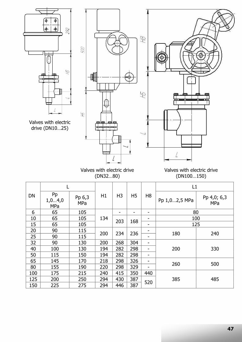
47
DN
L
H1 H3 H5 Н8
L1
Pр 1,0…4,0
MPa
Pр 6,3 MPa
Pр 1,0…2,5 MPa Pр 4,0; 6,3
MPa
6 65 105
134
- - - 80
10 65 105 203 168
- 100
15 65 105 - 125
20 90 115 200 234 236
- 180 240
25 90 115 -
32 90 130 200 268 304 -
200 330 40 100 130 194 282 298 -
50 115 150 194 282 298 -
65 145 170 218 298 326 - 260 500
80 155 190 220 298 329 -
100 175 215 240 415 350 440
385 485 125 200 250 294 430 387 520
150 225 275 294 446 387
Valves with electric drive (DN10…25)
Valves with electric drive
(DN32…80)
Valves with electric drive
(DN100…150)

48
Connection dimensions of angle valves Threaded end connection
DN L
D D1 l1 l d4 Pp 1,0…4,0 MPa Pp 6,3 MPa
6 65 105 М22х1,5 10 3 14 3/8”
10 65 105 М27х1,5 14 3 16 3/8”
15 65 105 М36х2 22 5 22 3/4”
20 90 115 М39х2 25 5 23 1”
25 90 115 М48х2 32 6 26 1¼”
Welding connection
Type 1 (Basic) Type 2

49
DN L
D h Pp 1,0…4,0 MPa Pp 6,3 MPa
6 100 100 11 8
10 130 160 15 10
15 130 175 20 10
20 150 190 27 10
25 160 200 32 10
32 180 210 37 12
40 200 225 47 12
50 230 300 57 12
65 290 340 67 15
80 310 380 82 15
100 350 430 102 25
125 400 500 127 25
150 480 550 154 25
Flanged connection
DN D D1 D2
D3 D4 b*
h h1
d n
1) 2) 3) 1) 2) 3) 1,0
MPa
1,6
MPa
2,5
MPa
4,0
MPa
6,3
MPa 1) 2) 3)
1,0;
1,6 MPa
2,5…
6,3 MPa
10 23 35 42 60 70 90 100 10 12 14 16
2 3 14
4
15 28 40 47 65 75 95 105 2 3 14
20 35 51 58 75 90 105 125 12 14 16 14 18 2 3 14 18
25 42 58 68 85 100 115 135 12 16 14 20 2 3 14 18
32 50 66 78 100 110 135 150 14 16 18 16 21 2 3 18 22
40 60 76 88 110 125 145 165 15 17 19 16 21 3 3 18 22
50 72 88 102 125 135 160 175 15 19 21 17 23 3 3 18 22
65 94 110 122 145 160 180 200 17 21 19 25 3 3 18 22 4 8
80 105 121 133 160 170 195 210 17 21 23 21 27 3 3 18 22 4 8
100 128 150 158 180 190 200 215 230 250 19 23 25 23 29 3 3 18 22 26
8 125 154 176 184 210 220 240 245 270 295 21 25 27 25 33 3 3 18 26 30
150 182 204 212 240 250 280 280 300 340 21 25 27 35 3 3 22 26 33
1) Рр 1,0; 1,6 MPa
2) Рр 2,5; 4,0 MPa
3) Рр 6,3 MPa
* For information
50
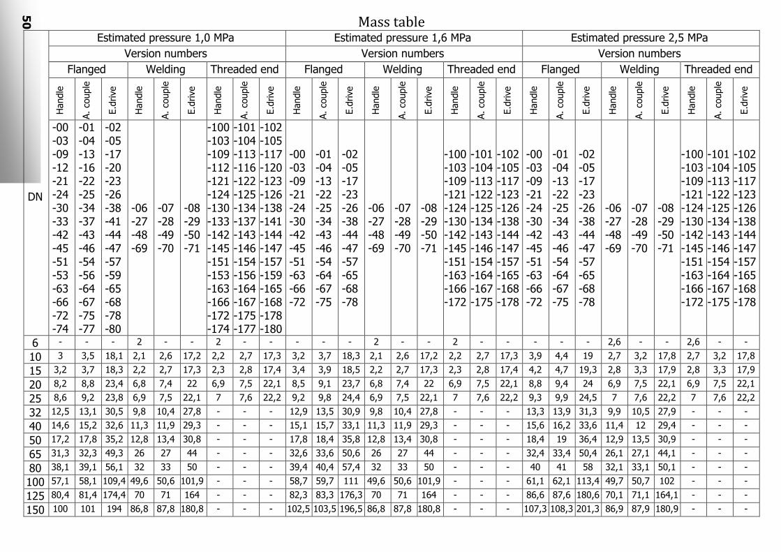
Mass table
DN
Estimated pressure 1,0 MPa Estimated pressure 1,6 MPa Estimated pressure 2,5 MPa
Version numbers Version numbers Version numbers
Flanged Welding Threaded end Flanged Welding Threaded end Flanged Welding Threaded end H
andle
A. co
uple
E.d
rive
Handle
A. co
uple
E.d
rive
Handle
A. co
uple
E.d
rive
Handle
A. co
uple
E.d
rive
Handle
A. co
uple
E.d
rive
Handle
A. co
uple
E.d
rive
Handle
A. co
uple
E.d
rive
Handle
A. co
uple
E.d
rive
Handle
A. co
uple
E.d
rive
-00 -03 -09 -12 -21 -24 -30 -33 -42 -45 -51 -53 -63 -66 -72 -74
-01 -04 -13 -16 -22 -25 -34 -37 -43 -46 -54 -56 -64 -67 -75 -77
-02 -05 -17 -20 -23 -26 -38 -41 -44 -47 -57 -59 -65 -68 -78 -80
-06 -27 -48 -69
-07 -28 -49 -70
-08 -29 -50 -71
-100 -103 -109 -112 -121 -124 -130 -133 -142 -145 -151 -153 -163 -166 -172 -174
-101 -104 -113 -116 -122 -125 -134 -137 -143 -146 -154 -156 -164 -167 -175 -177
-102 -105 -117 -120 -123 -126 -138 -141 -144 -147 -157 -159 -165 -168 -178 -180
-00 -03 -09 -21 -24 -30 -42 -45 -51 -63 -66 -72
-01 -04 -13 -22 -25 -34 -43 -46 -54 -64 -67 -75
-02 -05 -17 -23 -26 -38 -44 -47 -57 -65 -68 -78
-06 -27 -48 -69
-07 -28 -49 -70
-08 -29 -50 -71
-100 -103 -109 -121 -124 -130 -142 -145 -151 -163 -166 -172
-101 -104 -113 -122 -125 -134 -143 -146 -154 -164 -167 -175
-102 -105 -117 -123 -126 -138 -144 -147 -157 -165 -168 -178
6 - - - 2 - - 2 - - - - - 2 - - 2 - - - - - 2,6 - - 2,6 - -
10 3 3,5 18,1 2,1 2,6 17,2 2,2 2,7 17,3 3,2 3,7 18,3 2,1 2,6 17,2 2,2 2,7 17,3 3,9 4,4 19 2,7 3,2 17,8 2,7 3,2 17,8
15 3,2 3,7 18,3 2,2 2,7 17,3 2,3 2,8 17,4 3,4 3,9 18,5 2,2 2,7 17,3 2,3 2,8 17,4 4,2 4,7 19,3 2,8 3,3 17,9 2,8 3,3 17,9
20 8,2 8,8 23,4 6,8 7,4 22 6,9 7,5 22,1 8,5 9,1 23,7 6,8 7,4 22 6,9 7,5 22,1 8,8 9,4 24 6,9 7,5 22,1 6,9 7,5 22,1
25 8,6 9,2 23,8 6,9 7,5 22,1 7 7,6 22,2 9,2 9,8 24,4 6,9 7,5 22,1 7 7,6 22,2 9,3 9,9 24,5 7 7,6 22,2 7 7,6 22,2
32 12,5 13,1 30,5 9,8 10,4 27,8 - - - 12,9 13,5 30,9 9,8 10,4 27,8 - - - 13,3 13,9 31,3 9,9 10,5 27,9 - - -
40 14,6 15,2 32,6 11,3 11,9 29,3 - - - 15,1 15,7 33,1 11,3 11,9 29,3 - - - 15,6 16,2 33,6 11,4 12 29,4 - - -
50 17,2 17,8 35,2 12,8 13,4 30,8 - - - 17,8 18,4 35,8 12,8 13,4 30,8 - - - 18,4 19 36,4 12,9 13,5 30,9 - - -
65 31,3 32,3 49,3 26 27 44 - - - 32,6 33,6 50,6 26 27 44 - - - 32,4 33,4 50,4 26,1 27,1 44,1 - - -
80 38,1 39,1 56,1 32 33 50 - - - 39,4 40,4 57,4 32 33 50 - - - 40 41 58 32,1 33,1 50,1 - - -
100 57,1 58,1 109,4 49,6 50,6 101,9 - - - 58,7 59,7 111 49,6 50,6 101,9 - - - 61,1 62,1 113,4 49,7 50,7 102 - - -
125 80,4 81,4 174,4 70 71 164 - - - 82,3 83,3 176,3 70 71 164 - - - 86,6 87,6 180,6 70,1 71,1 164,1 - - -
150 100 101 194 86,8 87,8 180,8 - - - 102,5 103,5 196,5 86,8 87,8 180,8 - - - 107,3 108,3 201,3 86,9 87,9 180,9 - - -

51
Mass table (continue)
DN
Estimated pressure 4,0 MPa Estimated pressure 6,3 MPa
Version numbers Version numbers
Flanged Welding Threaded end Flanged Welding Threaded end
Handle
A. co
uple
E.d
rive
Handle
A. co
uple
E.d
rive
Handle
A. co
uple
E.d
rive
Handle
A. co
uple
E.d
rive
Handle
A. co
uple
E.d
rive
Handle
A. co
uple
E.d
rive
-00 -03 -09 -21 -24 -30 -42 -45 -51 -63 -66 -72
-01 -04 -13 -22 -25 -34 -43 -46 -54 -64 -67 -75
-02 -05 -17 -23 -26 -38 -44 -47 -57 -65 -68 -78
-06 -27 -48 -69
-07 -28 -49 -70
-08 -29 -50 -71
-100 -103 -109 -121 -124 -130 -142 -145 -151 -163 -166 -172
-101 -104 -113 -122 -125 -134 -143 -146 -154 -164 -167 -175
-102 -105 -117 -123 -126 -138 -144 -147 -157 -165 -168 -178
6 - - - 2,6 - - 2,6 - - - - - 4,5 - - 4,5 - -
10 4 4,5 19,1 2,7 3,2 17,8 2,7 3,2 17,8 6,7 7,2 21,8 4,7 5,2 19,8 4,7 5,2 19,8
15 4,5 5 19,6 2,9 3,4 18 2,9 3,4 18 7,4 7,9 22,5 5,1 5,6 20,2 5,1 5,6 20,2
20 8,8 9,4 24 6,9 7,5 22,1 6,9 7,5 22,1 12,2 12,8 27,4 8,6 9,2 23,8 8,6 9,2 23,8
25 9,3 9,9 24,5 7 7,6 22,2 7 7,6 22,2 13,2 13,8 28,4 8,7 9,3 23,9 8,7 9,3 23,9
32 13,6 14,2 31,6 9,9 10,5 27,9 - - - 16,7 17,3 34,7 10,9 11,5 28,9 - - -
40 15,7 16,3 33,7 11,4 12 29,4 - - - 20 20,6 38 12,5 13,1 30,5 - - -
50 18,4 19 36,4 12,9 13,5 30,9 - - - 23,4 24 41,4 14,2 14,8 32,2 - - -
65 33,4 34,4 51,4 26,1 27,1 44,1 - - - 41,1 42,1 59,1 28,7 29,7 46,7 - - -
80 41,7 42,7 59,7 32,1 33,1 50,1 - - - 49,7 50,7 67,7 35,3 36,3 53,3 - - -
100 64,2 65,2 116,5 49,7 50,7 102 - - - 76 77 128,3 54,7 55,7 107 - - -
125 90,3 91,3 184,3 70,1 71,1 164,1 - - - 110,9 111,9 204,9 77,1 78,1 171,1 - - -
150 113 114 207 86,9 87,9 180,9 - - - 144,5 145,5 238,5 95,6 96,6 189,6 - - -

52
The correspondence table of valve versions under ТУ 3742-003-57180370-2005 and figure identifications of Central Constructor Valve Building Bureau
Main parts material
12Х18Н10Т 10Х17Н13М3Т Steel 20
Version Figure
identification Version
Figure identification
Version Figure
identification
КЗО 0205.ХХХ.YY-00 14нж17ст1 -21 14нж17ст2 -42 14с17ст3
-01, -101 14нж017ст4 -22, -122 14нж017ст5 -43, -143 14с017ст6
-02, -102 14нж917ст7 -23, -123 14нж917ст8 -44, -144 14с917ст9
-03, -103 14нж17ст10 -24, -124 14нж17ст11 -45, -145 14с17ст12
-04, -104 14нж017ст13 -25, -125 14нж017ст14 -46, -146 14с017ст15
-05, -105 14нж917ст16 -26, -126 14нж917ст17 -47, -147 14с917ст18
-06 14нж17ст19 -27 14нж17ст20 -48 14с17ст21
-07 14нж017ст22 -28 14нж017ст23 -49 14с017ст24
-08 14нж917ст25 -29 14нж917ст26 -50 14с917ст27
-09, -109 14нж17п28-1 -30, -130 14нж17п29-1 -51, -151 14с17п30-1
-12, -112 14нж17р28-4 -33, -133 14нж17р29-4 -53, -153 14с17р30-4
-13, -113 14нж017п31-1 -34, -134 14нж017п32-1 -54, -154 14с017п33-1
-16, -116 14нж017р31-4 -37, -137 14нж017р32-4 -56, -156 14с017р33-4
-17, -117 14нж917п34-1 -38, -138 14нж917п35-1 -57, -157 14с917п36-1
-20, -120 14нж917р34-4 -41, -141 14нж917р35-4 -59, -159 14с917р36-4
КЗО 0206.ХХХ.YY-00 15нж66ст1 -21 15нж66ст2 -42 15с66ст3
-01, -101 15нж066ст4 -22, -122 15нж066ст5 -43, -143 15с066ст6
-02, -102 15нж966ст7 -23, -123 15нж966ст8 -44, -144 15с966ст9
-03, -103 15нж66ст10 -24, -124 15нж66ст11 -45, -145 15с66ст12
-04, -104 15нж066ст13 -25, -125 15нж066ст14 -46, -146 15с066ст15
-05, -105 15нж966ст16 -26, -126 15нж966ст17 -47, -147 15с966ст16
-06 15нж66ст19 -27 15нж66ст20 -48 15с66ст21
-07 15нж066ст22 -28 15нж066ст23 -49 15с066ст24
-08 15нж966ст25 -29 15нж966ст26 -50 15с966ст27
-09, -109 15нж66п28-1 -30, -130 15нж66п29-1 -51, -151 15с66п30-1
-12, -112 15нж66р28-4 -33, -133 15нж66р29-4 -53, -153 15с66р30-4
-13, -113 15нж066п31-1 -34, -134 15нж066п32-1 -54, -154 15с066п33-1
-16, -116 15нж066р31-4 -37, -137 15нж066р32-4 -56, -156 15с066р33-4
-17, -117 15нж966п34-1 -38, -138 15нж966п35-1 -57, -157 15с966п36-1
-20, -120 15нж966р34-4 -41, -141 15нж966р35-4 -59, -159 15с966р36-4
КЗО 0208.ХХХ.YY-00 15нж40ст1 -21 15нж40ст2 -42 15с40ст3
-01, -101 15нж040ст4 -22, -122 15нж040ст5 -43, -143 15с040ст6
-02, -102 15нж940ст7 -23, -123 15нж940ст8 -44, -144 15с940ст9
-03, -103 15нж40ст10 -24, -124 15нж40ст11 -45, -145 15с40ст12
-04, -104 15нж040ст13 -25, -125 15нж040ст14 -46, -146 15с040ст15
-05, -105 15нж940ст16 -26, -126 15нж940ст17 -47, -147 15с940ст16
-06 15нж40ст19 -27 15нж40ст20 -48 15с40ст21
-07 15нж040ст22 -28 15нж040ст23 -49 15с040ст24
-08 15нж940ст25 -29 15нж940ст26 -50 15с940ст27
-09, -109 15нж40п28-1 -30, -130 15нж40п29-1 -51, -151 15с40п30-1
-12, -112 15нж40р28-4 -33, -133 15нж40р29-4 -53, -153 15с40р30-4
-13, -113 15нж040п31-1 -34, -134 15нж040п32-1 -54, -154 15с040п33-1
-16, -116 15нж040р31-4 -37, -137 15нж040р32-4 -56, -156 15с040р33-4
-17, -117 15нж940п34-1 -38, -138 15нж940п35-1 -57, -157 15с940п36-1
-20, -120 15нж940р34-4 -41, -141 15нж940р35-4 -59, -159 15с940р36-4
-10 14нж1р -52 14с1р

53
2 and 3 SAFETY CLASS VALVES
Area of utilization Valves are designed for working as shut-off devices in systems of nuclear
power plants with water-moderated water-cooled power reactors, high-power channel-type reactors, fast neutron reactors in compliance with class and group of valves, including 4 safety class systems under НП-001-97 (ОПБ-88/97).
Valves are allowed to be used in marine nuclear power plants and their supply objects, storage and recycling stations of nuclear fuel.
Working conditions
Valves keep their operating capacity by normal working in maintainable areas of nuclear power plants, out of blanket at following parameters of environment:
Temperature – from +5 to +45°С Pressure – 0,1 MPa Relative Humidity – 75 % at 45 °С Parameters of environment in the hermetic blanket of nuclear power plants
with water-moderated water-cooled power reactor are noted on the page 52. Parameters of environment in the hermetic blanket of nuclear power plants
with high-power channel-type reactor are noted on the page 52. Valves are allowed to be used in systems with following working medium: – valves made of steel 08Х18Н10Т – 1st circuit coolant, steam-gas
composition, distillate, supply water, condensate, air, nitrogen, decontamination solution, wash solution;
– valves made of steel 20 – oil, steam, condensate, supply water, air, nitrogen, inert gases, decontamination solution, wash solution, technical water (chloride content up to 300 мg/l, oxygen content up to до 20 мg/l).
General feature
1) Valve identification under НП-001-97 – 2НЗЛО, 3НЗЛО. 2) Pipeline connection is welding. 3) Branch pipe grooving is shown on the page 60 and page 67 (except
valves for control equipment). 3) Working position of valve in pipeline is any position except position with
electric drive downwards. 4) The gate seal is built-up welding. 5) Working medium feed path is any (on gate and under gate). 6) Specified life time (till overhaul) – 1500 cycles. 7) Specified service life (till overhaul) – 15 years. 8) Body parts specified life time – 40 years. 9) Electric drives specified service life – 20 years. 10) Category of earthquake resistance is I under НП-031-01.
54
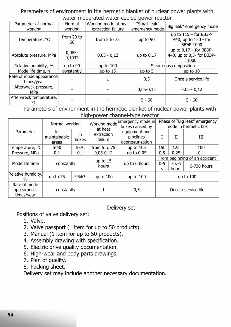
Parameters of environment in the hermetic blanket of nuclear power plants with water-moderated water-cooled power reactor
Parameter of normal working
Normal working
Working mode at heat extraction failure
“Small leak” emergency mode
“Big leak” emergency mode
Temperature, °С from 20 to
60 from 5 to 75 up to 90
up to 115 – for ВВЭР-440, up to 150 - for
ВВЭР-1000
Absolute pressure, MPa 0,085-0,1032
0,05 - 0,12 up to 0,17 up to 0,17 – for ВВЭР-
440, up to 0,5- for ВВЭР-1000
Relative humidity, % up to 90 up to 100 Steam-gas composition
Mode life time, h constantly up to 15 up to 5 up to 10
Rate of mode appearance, times/year
- 1 0,5 Once a service life
Afterwreck pressure, MPa
- - 0,05-0,12 0,05 - 0,12
Afterwreck temperature, °С
- - 5 - 60 5 - 60
Parameters of environment in the hermetic blanket of nuclear power plants with high-power channel-type reactor
Parameter
Normal working Working mode at heat
extraction failure
Emergency mode in boxes caused by equipment and
pipelines depressurization
Phase of “Big leak” emergency mode in hermetic box
in maintainable
areas
in boxes
I II III
Temperature, °С 5-40 5-70 from 5 to 75 up to 105 150 125 100
Pressure, MPa 0,1 0,1 0,05-0,12 up to 0,05 0,5 0,25 0,1
Mode life time constantly up to 15 hours
up to 6 hours
From beginning of an accident
0-5 s
5 s-6 hours
6-720 hours
Relative humidity, %
up to 75 95±3 up to 100 up to 100 up to 100
Rate of mode appearance, times/year
constantly 1 0,5 Once a service life
Delivery set
Positions of valve delivery set: 1. Valve. 2. Valve passport (1 item for up to 50 products). 3. Manual (1 item for up to 50 products). 4. Assembly drawing with specification. 5. Electric drive quality documentation. 6. High-wear and body parts drawings. 7. Plan of quality. 8. Packing sheet.
Delivery set may include another necessary documentation.
127

55
HIGH PRESSURE VALVES КЗА 0209 ТУ 3742-011-57180370-2009
Arrangement 14 13 12 11 10 9 8 7 6 5 4 3 2 1

56
A material of main parts
Pos. Name
Material
For versions made of steel 08Х18Н10Т
For versions made of steel 20
1 Body 08Х18Н10Т Steel 20
2 Spool 08Х18Н10Т
3 Bellows junction
Bellows 08Х18Н10Т
Ring 08Х18Н10Т
Ring 08Х18Н10Т
Ring 08Х18Н10Т
Spindle 08Х18Н10Т/14Х17Н2
4 Ring Graphite
5 Transitional bush 08Х18Н10Т Steel 20
6 Gland bush 08Х18Н10Т Steel 20
7 Cover 08Х18Н10Т Steel 20
8 Seal rings Graphite
9 Gland bush 08Х18Н10Т Steel 20
10 Clamp nut 14Х17Н2
11 Threaded bush БрАЖН 10-4-4
12 Bearing
13 Bearing nut 14Х17Н2
14 Local indicator of gate
position
Valve identity under НП-068-05 - 2ВIIа, 2ВIIIа, 3СIIIа
VALVE IDENTIFICATION FORM
When placing an order for valve you must specify: 1. The valve name
КЗА 0209-010М1-04
1.1 1.2 1.3 1.4
1.1. КЗА 0209 – high pressure valves general identity. 1.2. 010 – nominal diameter. 1.3. М1 –2 and 3 class of safety under НП-001-97 valves general identity. 1.4. 04 – version variant (in compliance with Table of versions).
2. Classification valve identity under НП-068-05 (2ВIIа, 2ВIIIа, 3СIIIa)
The example of valve identification Bellows shut-off valve КЗА 0209-020М1-12-П 2ВIIIа, 2Н, ТУ 3742-011-
57180370-2009. The following demands may be set additionally when placing an order: - the type of electric drive (in case customer needs electric drive different
from electric drive noted in electric drives table). - the type of branch pip grooving (in case customer needs grooving different
from grooving noted in catalog); - other demands.

57
КЗА 0209 TABLE OF VERSIONS
DN Name Control
Steel 08Х18Н10Т Steel 20
With shifted branch pipes With line branch pipes With shifted
branch pipes
With line
branch pipes
Estimated pressure, MPa
20 18 14 11 9,2 20 18 14 11 9,2 12 (8,6); (6)
Estimated temperature, ⁰С
300 350 335 300 290 300 350 335 300 290 250 (300); (275)
10
15 20
25
КЗА 0209-ХХХМ1
Handle -04 -02 -001 -22 -20 -18 -03 -21
Handle with lock -13 -05 -01 -31 -23 -19 -36 -46
Handle with limit
switch set -42 -40 -38 -52 -50 -48 -44 -54
Handle with lock
and limit switch
set
-43 -41 -39 -53 -51 -49 -45 -55
Articulated
coupling -10 -08 -06 -28 -26 -24 -09 -27
Articulated coupling
through right-angle reducer
-17 -11 -07 -35 -29 -25 -37 -47
Electric drive for
installation in the maintainable
area
-16-П -14-П -12-П -34-П -32-П -30-П -15-П -33-П
Electric drive for installation
under the blanket
-16-О -14-О -12-О -34-О -32-О -30-О -15-О -33-О
1 -00 is not specified in valve name ХХХ – nominal diameter (010, 015, 020, 025)
ELECTRIC DRIVES TABLE
DN Electric drive for installation in the maintainable area
Electric drive for installation under the blanket
10 2-ПМ-22 (0,025 kW) 2-ОМ-22 (0,025 kW)
15
20 2-ПА-02 (0,18 kW) 2-ОА-02 (0,18kW)
25

58
DRAWINGS AND SPECIFICATIONS VALVES WITH SHIFTED BRANCH PIPES
DN
Rotational power on
output spindle for shut/open,
Н×m
Coefficient of resistance
on/under the spool
Place of installation
Mass, kg
L H h L1 H1
10 23,2/25 4,0/4,0 in the
maintainable area, under the blanket
13,5 130 24 45 170 240
15 23,2/25 4,5/4,5 13,5 130 24 45 170 240
20 45,5/60 5,4/5,6 20 160 35 73 230 305
25 45,5/60 6,4/6,9 20 160 35 73 230 305
Technical feature is shown for handle versions. Drawings and technical feature of versions with other types of control are given on demand.
Branch pipe grooving for different versions
DN Versions
Versions made of steel 08Х18Н10Т Versions made of steel 20
10
С-23
С-22
15
С-23 20
25

59
MAIN DIMENSIONS AND SPECIFICATIONS VALVES WITH LINE BRANCH PIPES
DN
Rotational power on
output spindle for shut/open,
Н×m
Coefficient of resistance
on/under the spool
Place of installation
Mass, kg
L h L1 H1
10 23,2/25 5,0/5,7 in the
maintainable area, under the blanket
13,5 130 21 170 264
15 23,2/25 5,0/5,7 13,5 130 21 170 264
20 45,5/60 5,5/6,3 20 160 38 230 340
25 45,5/60 9,0/7,5 20 160 38 230 340
Technical feature is shown for handle versions. Drawings and technical feature of versions with other types of control are given on demand.
Branch pipe grooving for different versions
DN Versions
Versions made of steel 08Х18Н10Т Versions made of steel 20
10
С-23
С-22
15 С-23
20 С-23
25 С-23

60
The drawings of branch pipe grooving
DN
Рр, MPa
08Х18Н10Т Steel 20
20,0 14,0 11,0 12,0
D D0 D D0 D D0 D D0
10 14 10+0,3 14 10+0,3 14 10+0,3 16 12+0,43
15 18 13+0,3 18 13+0,3 18 13+0,3 18 15+0,43
20 25 19+0,3 25 19+0,3 25 19+0,3 28 22+0,43
25 32 25+0,3 32 25+0,3 32 25+0,3 32 26+0,52
The C-23 grooving
The C-22 grooving

61
LOW PRESSURE VALVES КЗА 0208, КЗА 0210 ТУ 3742-010-57180370-2008
Arrangement (series КЗА 0208 as an example)
7
6
5
4
3
2
1

62
A material of main parts
Pos. Name
Material
For versions made of steel 08Х18Н10Т
For versions made of steel 20
1 Body 08Х18Н10Т Steel 20
2 Spool 08Х18Н10Т
3 Bellows junction
Bellows 08Х18Н10Т
Ring 08Х18Н10Т
Ring 08Х18Н10Т
Ring 08Х18Н10Т
Spindle 08Х18Н10Т/14Х17Н2
4 Transitional bush 08Х18Н10Т Steel 20
5 Threaded bush БрАЖН 10-4-4
6 Cover 08Х18Н10Т Steel 20
7 Local indicator of gate
position
Valve identity under НП-068-05: Pp 1,0MPa - 2ВIIв, 2ВIIIс, 3СIIIс Рр 2,5; 4,0MPa – 2ВIIв, 2ВIIIв, 3СIIIв
IDENTIFICATION FORM OF VALVE
When placing an order for valve you must specify: 1. The valve name
КЗА 0208-010М1-01
1.1 1.2 1.3 1.4
1.1. КЗА 0208 – valves with shifted branch pipes general identity; КЗА 0210 – valves with line branch pipes general identity.
1.2. 010 – nominal diameter. 1.3. М1 –2 and 3 class of safety under НП-001-97 valves general identity. 1.4. 04 – version variant (in compliance with Table of versions).
2. Classification valve identity under НП-068-05. 3. Estimated temperature (basic 250⁰С)
The example of valve identification
Bellows shut-off valve КЗА 0210-020М1-03-П 2ВIIIв, 2Н, 250⁰С, ТУ 3742-010-
57180370-2008. The following demands may be set additionally when placing an order: - the type of electric drive (in case customer needs electric drive different from
electric drive noted in electric drives table). - the type of branch pip grooving (in case customer needs grooving different
from grooving noted in catalog); - other demands.

63
Table of versions
DN Name Control
A material of main parts
Steel 08Х18Н10Т Steel 20
Estimated pressure, MPa
1,0 2,5 4,0 1,0 2,5 4,0
Estimated pressure, ⁰С
250 (450) 250
10 15
20
25 32
40 50
65 80
100
125 150
КЗА 0208-XXXМ1 КЗА 0210-XXXМ12
Handle -001 -08 -20 -04 -12 -24
Handle with lock -28 -34 -40 -31 -37 -43
Handle with limit switch set
-29 -35 -41 -32 -38 -44
Handle with lock
and limit switch set
-30 -36 -42 -33 -39 -45
Articulated
coupling -01 -09 -21 -05 -13 -25
Articulated
coupling through right-angle
reducer
-02 -10 -22 -06 -14 -26
Electric drive for installation in the
maintainable area
-03-П -11-П -23-П -07-П -15-П -27-П
Electric drive for installation under
the blanket
-03-О -11-О -23-О -07-О -15-О -27-О
XXX means nominal diameter (010, 015, 020, 025, 032, 040, 050, 065, 080, 100, 125, 150) 1 -00 is not specified in valve name
2 Maximum nominal diameter for КЗА 0210 series is 100
ELECTRIC DRIVES TABLE
DN
Electric drive for installation in the maintainable area
Electric drive for installation under the blanket
Pp, MPa Pp, MPa
1,0 2,5 4,0 1,0 2,5 4,0
10 2-ПМ-12 (0,025 kW) 2-ОМ-12 (0,025 kW)
15
20 2-ПМ-21 (0,025 kW) 2-ОМ-21 (0,025 kW)
25
32 2-ПМ-22 (0,025 kW) 2-ОМ-22 (0,025 kW)
40
50 2-ПМ-22 (0,025 kW) 2-ПА-03
(0,18 kW) 2-ОМ-22 (0,025 kW)
2-ОА-03 (0,18 kW)
65 2-ПА-35 (0,18 kW) 2-ОА-35 (0,18 kW)
80 2-ПА-35 (0,18 kW) 2-ПБ-04 (1,7 kW)
2-ОА-35 (0,18 kW) 2-ОБ-04 (1,7 kW)
100 2-ПА-35
(0,18 kW) 2-ПБ-05 (1,7 kW)
2-ОА-35 (0,18 kW)
2-ОБ-05 (1,7 kW)
125 2-ПБ-05 (1,7 kW) 2-ОБ-05 (1,7 kW)
150 2-ПБ-05 (1,7 kW)
2-ПВ-04 (3,2 kW) 2-ОБ-05 (1,7 kW)
2-ОВ-04 (3,2 kW)

64
DRAWINGS AND SPECIFICATIONS VALVES WITH SHIFTED BRANCH PIPES КЗА 0208
DN
Rotational power on
output spindle for shut/open,
Н×m
Coefficient of resistance
on/under the spool
Place of installation
Mass, kg L H h
10 7/4 9,0/7,5
in the maintainable area, under the blanket
4 130 24 35
15 7/4 9,0/7,5 4 130 24 35
20 22/19 9,0/7,5 8,2 160 35 66
25 22/19 9,0/7,5 8,2 160 35 66
32 23/21 9,0/7,5 10 180 45 76 40 24/21 9,0/7,5 16,5 180 45 86 50 25/21 7,0/5,5 16,5 230 70 106 65 70/60 7,0/5,5 37,5 340 110 130 80 75/60 7,0/5,5 40 380 140 153 100 90/70 7,0/5,5 65 430 160 223 125 200/170 7,0/5,5 95 550 210 297 150 240/210 7,0/5,5 146 550 210 288
Technical feature is shown for versions with handle. Drawings and technical feature of versions with other types of control are given on demand.
Valve version with handle
Valve version with electric drive

65
VALVES WITH LINE BRANCH PIPES КЗА 0210
Valve version with electric drive
Valve version with handle
Valve version with handle and lock
Valve version intended for articulated couple connection

66
DN
Rotational power on
output spindle for shut/open,
Н×m
Coefficient of resistance
on/under the spool
Place of installation
Mass, kg L h
10 7/4 8,5/7,0
in the maintainable area, under the blanket
4 130 20
15 7/4 8,5/7,0 4 130 20
20 22/19 8,5/7,0 8,2 160 25
25 22/19 8,5/7,0 8,2 160 25
32 23/21 8,5/7,0 10 180 30 40 24/21 8,5/7,0 16,5 180 32 50 25/21 6,5/5,0 16,5 230 40 65 70/60 6,5/5,0 37,5 340 45 80 75/60 6,5/5,0 40 380 55 100 90/70 6,5/5,0 65 430 65
Technical feature is shown for versions with handle. Drawings and technical feature of versions with other types of control are given on demand.
Branch pipe grooving for valves КЗА 0208, КЗА 0210
DN
Versions
Versions made of steel 08Х18Н10Т
Versions made of steel 20
Estimated pressure 1,0; 2,5 MPa
Estimated pressure 4,0 MPa
10
С-23
С-23 С-22
15
C-23
20
25
32
40
50
65
C-42
80
100
125
150

67
The drawings of branch pipe grooving for valves КЗА 0208, КЗА 0210
DN 1,0; 2,5MPa 4,0MPa
D d0 D d0
08Х18Н10Т Steel 20 08Х18Н10Т Steel 20
10 14 10,5+0,18 11,0+0,18 * 10,0+0,3 12,0+0,43
15 18 13,5+0,18 15,0+0,18 18 13,0+0,3 15,0+0,18
20 25 19,0+0,30 22,0+0,21 25 19,0+0,3 22,0+0,43
25 32 28,0+0,21 29,0+0,21 32 25,0+0,3 26,0+0,52
32 38 33,0+0,25 35,0+0,25 38 31,0+0,3 32,0+0,62
40 48 41,0+0,25 41,0+0,25 48 41,0+0,25 41,0+0,25
50 57 52,0+0,30 52,0+0,30 57 50,0+0,3 49,0+0,62
65 76 68,0+0,30 71,0+0,30 76 68,0+0,3 68,0+0,46
80 89 80,0+030 84,0+035 89 80,0+0,3 81,0+0,54
100 108 99,0+0,35 102,0+0,35 108 100,0+0,23 97,0+0,54
125 133 124,0+0,40 127,0+0,40 133 124,0+0,23 122,0+0,63
150 159 150,0+0,40 151,0+0,40 159 149,0+0,26 148,0+0,63
The С-23 grooving The C-42 grooving
The С-22 grooving

171
68
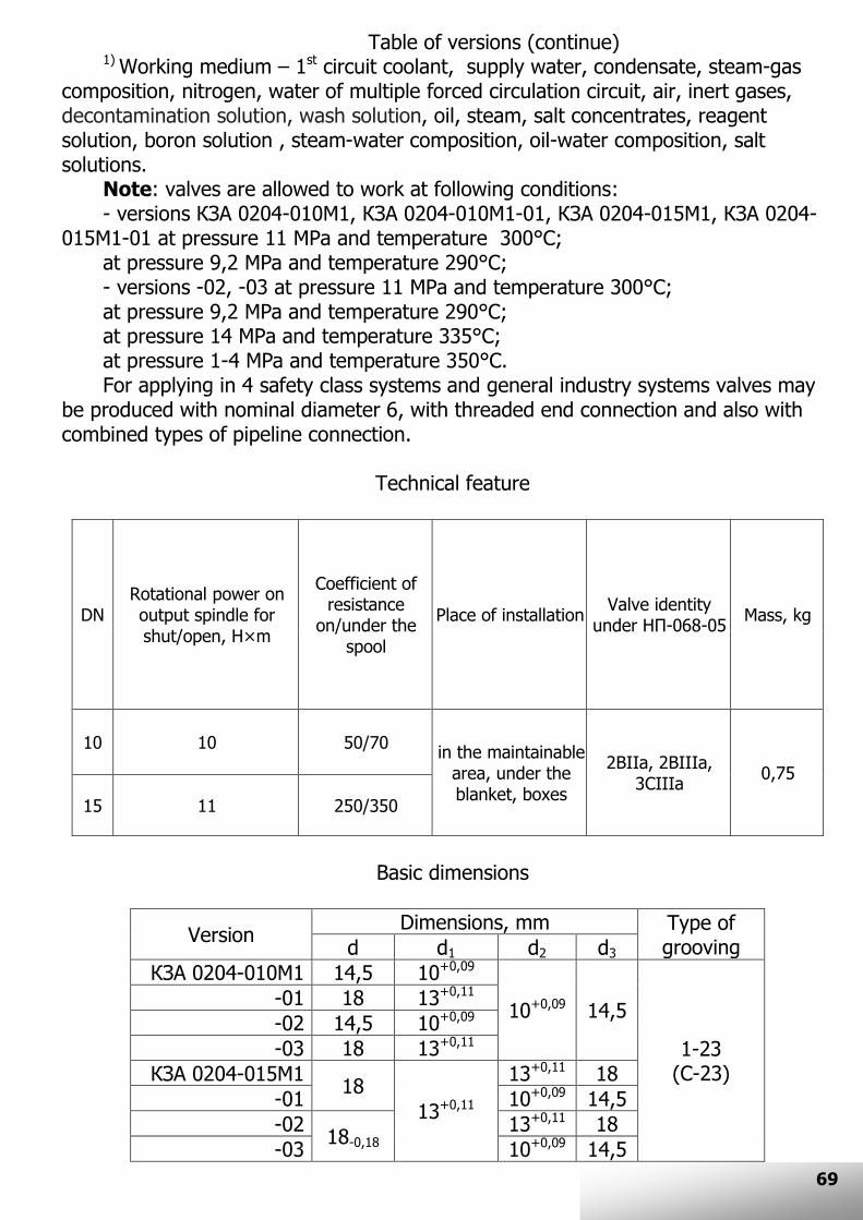
VALVES FOR CONTROL EQUIPMENT КЗА 0204 ТУ 3742-004-57180370-2010
Main parts: 1 - Body 2 – Cover 3 – Bellows 4 –Bush 5 – Spindle 6 – Ring 7 – Bush 8 – Bearing * - demounting
dimension
Area of utilization
The valves are designed for installation on impulse pipelines or drain-blowoff lines for control equipment connection or disconnection in systems of nuclear power plants.
Working conditions, general feature are noted on the page 53.
Table of versions
Version DN Estimated pressure,
MPa
Estimated temperature,
ºС
Working medium
Body material
Control
КЗА 0204-010М1
10
20 300
1) Steel 08Х18Н10Т
Handle
-01
-02 18 350
-03
КЗА 0204-015М1
15
20 300 -01
-02 18 350
-03
69
Table of versions (continue) 1) Working medium – 1st circuit coolant, supply water, condensate, steam-gas
composition, nitrogen, water of multiple forced circulation circuit, air, inert gases, decontamination solution, wash solution, oil, steam, salt concentrates, reagent solution, boron solution , steam-water composition, oil-water composition, salt solutions.
Note: valves are allowed to work at following conditions: - versions КЗА 0204-010М1, КЗА 0204-010М1-01, КЗА 0204-015М1, КЗА 0204-
015М1-01 at pressure 11 MPa and temperature 300°С; at pressure 9,2 MPa and temperature 290°С; - versions -02, -03 at pressure 11 MPa and temperature 300°С; at pressure 9,2 MPa and temperature 290°С; at pressure 14 MPa and temperature 335°С; at pressure 1-4 MPa and temperature 350°С. For applying in 4 safety class systems and general industry systems valves may
be produced with nominal diameter 6, with threaded end connection and also with combined types of pipeline connection.
Technical feature
DN Rotational power on output spindle for shut/open, Н×m
Coefficient of resistance
on/under the spool
Place of installation Valve identity
under НП-068-05 Mass, kg
10 10 50/70 in the maintainable
area, under the blanket, boxes
2ВIIа, 2ВIIIа, 3СIIIа
0,75
15 11 250/350
Basic dimensions
Version Dimensions, mm Type of
grooving d d1 d2 d3
КЗА 0204-010М1 14,5 10+0,09
10+0,09 14,5
1-23 (С-23)
-01 18 13+0,11
-02 14,5 10+0,09
-03 18 13+0,11
КЗА 0204-015М1 18
13+0,11
13+0,11 18
-01 10+0,09 14,5
-02 18-0,18
13+0,11 18
-03 10+0,09 14,5
* - демонтажный размер

70
Small series valves Safety valves ПКП
ТУ 3742-001-57180370-2010
DN L L1 h h1 H H1 M D
10 65 90 55 80 240 283 М27х1,5 90
15 65 90 55 80 240 283 М36х2 95
20 70 110 63 110 265 305 М39х2 105
25 70 110 63 110 265 305 М48х2 115
Area of utilization Safety valves are designed to protect the equipment from pressure exceeding
over the acceptable value. Safety valves are used on tanks, boilers and pipelines for automatic escape of working medium into the open air or lateral pipeline.
Principle of operation A valve operates the next way:
The working medium is delivered into the inlet fitting of preliminarily adjusted to a certain actuation pressure valve. When pressure in the inlet fitting exceeds the acceptable value the gate opens and the escape of working medium into the outlet fitting occurs. When working medium pressure value lowers down to the adjust pressure value the gate shuts the flow area.
Version with threaded end connection
Version with flanged connection

71
Technical feature 1) Nominal diameter – 10, 15, 20, 25 2) Working medium – liquid and gaseous ammonia (R717), freon (R12,R22,R502), water, air, liquid coolants (water solution of CaCl2, ethylene glycol, methylene chloride – freon 30); for versions made of steel 10Х17Н13М3Т (10Х17Н13М2Т) – high-concentrated hydrogen peroxide, concentrated acids and other corrosive medium. 3) Nominal pressure – PN25. 4) Working pressure interval – 0,5-2,5 MPa. 5) Opposite pressure in outlet of valve – atmospheric. 6) Estimated temperature – from -50 to +200°С. 7) Environment temperature: for versions made of steel 20 – from -40 to +50°С; for versions made of steel 12Х18Н10Т, 10Х17Н13М3Т – from -50 to +50°С; for versions made of steel 09Г2С – from -60 to +50°С. 8) Pipeline connection – threaded end, flanged. 9) Gate seal – polytetrafluorethylene. 10) Gate leaktightness class – class А under GOST 9544. 11) Installation position – any position in upper hemisphere (45° vertical axes deviation). 12) Specified life – not less 12 years or 5000 cycles.
Table of versions
DN Pipeline
connection
Adjust pressure,
MPa
Body material
12Х18Н10Т Steel 20 10Х17Н13М3Т 09Г2С
10
threaded end
0,5-0,8 ПКП 10.00 ПКП 10.10 ПКП 10.20 ПКП 10.30
0,8-1,6 ПКП 10.00-01 ПКП 10.10-01 ПКП 10.20-01 ПКП 10.30-01
1,6-2,5 ПКП 10.00-02 ПКП 10.10-02 ПКП 10.20-02 ПКП 10.30-02
flanged
0,5-0,8 ПКП 10.01 ПКП 10.11 ПКП 10.21 ПКП 10.31
0,8-1,6 ПКП 10.01-01 ПКП 10.11-01 ПКП 10.21-01 ПКП 10.31-01
1,6-2,5 ПКП 10.01-02 ПКП 10.11-02 ПКП 10.21-02 ПКП 10.31-02
15
threaded end
0,5-0,8 ПКП 15.00 ПКП 15.10 ПКП 15.20 ПКП 15.30
0,8-1,6 ПКП 15.00-01 ПКП 15.10-01 ПКП 15.20-01 ПКП 15.30-01
1,6-2,5 ПКП 15.00-02 ПКП 15.10-02 ПКП 15.20-02 ПКП 15.30-02
flanged
0,5-0,8 ПКП 15.01 ПКП 15.11 ПКП 15.21 ПКП 15.31
0,8-1,6 ПКП 15.01-01 ПКП 15.11-01 ПКП 15.21-01 ПКП 15.31-01
1,6-2,5 ПКП 15.01-02 ПКП 15.11-02 ПКП 15.21-02 ПКП 15.31-02
20
threaded end
0,5-0,8 ПКП 20.00 ПКП 20.10 ПКП 20.20 ПКП 20.30
0,8-1,6 ПКП 20.00-01 ПКП 20.10-01 ПКП 20.20-01 ПКП 20.30-01
1,6-2,5 ПКП 20.00-02 ПКП 20.10-02 ПКП 20.20-02 ПКП 20.30-02
flanged
0,5-0,8 ПКП 20.01 ПКП 20.11 ПКП 20.21 ПКП 20.31
0,8-1,6 ПКП 20.01-01 ПКП 20.11-01 ПКП 20.21-01 ПКП 20.31-01
1,6-2,5 ПКП 20.01-02 ПКП 20.11-02 ПКП 20.21-02 ПКП 20.31-02
25
threaded end
0,5-0,8 ПКП 25.00 ПКП 25.10 ПКП 25.20 ПКП 25.30
0,8-1,6 ПКП 25.00-01 ПКП 25.10-01 ПКП 25.20-01 ПКП 25.30-01
1,6-2,5 ПКП 25.00-02 ПКП 25.10-02 ПКП 25.20-02 ПКП 25.30-02
flanged
0,5-0,8 ПКП 25.01 ПКП 25.11 ПКП 25.21 ПКП 25.31
0,8-1,6 ПКП 25.01-01 ПКП 25.11-01 ПКП 25.21-01 ПКП 25.31-01
1,6-2,5 ПКП 25.01-02 ПКП 25.11-02 ПКП 25.21-02 ПКП 25.31-02

72
Three-way valves КТХ 0204 ТУ 3742-002-57180370-2004
Area of utilization
Three-way valves are designed for installation in the pipelines as a working medium flow shift devices. The valves have one inlet fitting and two outlet fittings.
Table of versions
PN DN Name Body material
12Х18Н10Т Steel 20 10Х17Н13М3Т 09Г2С
25
10 КТХ 0204-010
-00 (type 1) -10 (type 2)
-01 (type 1)
-11 (type 2)
-02 (type 1) -12 (type 2)
-03 (type 1)
-13 (type 2)
15 КТХ 0204-015
20 КТХ 0204-020
25 КТХ 0204-025
32 КТХ 0204-032
40
10 КТХ 0204-010
-20 (type 1) -30 (type 2)
-21 (type 1)
-31 (type 2)
-22 (type 1) -32 (type 2)
-23 (type 1)
-33 (type 2)
15 КТХ 0204-015
20 КТХ 0204-020
25 КТХ 0204-025
32 КТХ 0204-032
Type 1 Type 2

73
Dimensions DN L H H1 M
10 140 75 180 М27х1,5
15 140 75 180 М36х2
20 152 90 204 М39х2
25 152 90 204 М48х2
32 180 120 250 М56х2
Technical feature
1) Estimated pressure – 2,5; 4,0 MPa. 2) Type of control – handle. 3) Working medium: - for versions -00, -02, -10, -12, -20, -22, -30, -32 – liquid and gaseous ammonia (R717), freons (R12,R22,R502), water, air, liquid coolants (water solution of CaCl2, ethylene glycol, methylene chloride – freon 30), gas, steam, gasoline, diesel fuel; -for versions -01, -03, -11, -13, -21, -23, -31, -33 – liquid and gaseous ammonia (R717), air, gas, steam, gasoline, diesel fuel. 4) Estimated temperature – from -50 to +200°С. 5) Environment temperature: for versions made of steel 20 – from -40 to +50°С; for versions made of steel 12Х18Н10Т, 10Х17Н13М3Т – from -50 to +50°С; for versions made of steel 09Г2С – from -60 to +50°С. 6) Installation position is any position. 7) Pipeline connection:
- type 1 – inlet fitting is made as threaded end version 2 under GOST 2822, outlet fittings are made as jimmer parts of threaded end connection under GOST 5890;
- type 2 – inlet fitting is made as jimmer parts of threaded end connection under GOST 5890, outlet fittings are made as threaded end version 2 under GOST 2822;
- on demand valves may be produced with combined types of pipeline connection including flanged connection, union joint or welding connection in any combinations. 8) Gate seal – polytetrafluorethylene. 9) Gate leaktightness class – class А under GOST 9544. 10) Specified life – not less 12 years or 5000 cycles. 12) Valves may be produced with angle disposition of lower outlet fitting.

74
Addition 1. Bellows valves factory length (except КЗА 0204)
DN
L Full-flow valves
КЗО 0205, КЗО 0206 КЗО 0208 all
versions except -10, -31, -52, -73 PN10…40
Full-flow valves КЗО 0205, КЗО 0206
КЗО 0208 PN63
Angle valves
КЗО 0207 PN10…40
Angle valves
КЗО 0207 PN63
Full-flow valves
КЗО 0208 versions
-10, -31, -52, -73
Valves КЗА 0208, КЗА 0210, КЗА 0209
3 - - - - 65 - 6 100 100 65 105 92 -
10 130 160 65 105 92 130 15 130 175 65 105 144 130 20 150 190 90 115 144 160 25 160 200 90 115 - 160 32 180 210 90 130 - 180 40 200 225 100 130 - 180 50 230 300 115 150 - 230 65 290 340 145 170 - 340 80 310 380 155 190 - 380 100 350 430 175 215 - 430 125 400 500 200 250 - 550
150 480 550 225 275 - 550
Valves with shifted branch pipes Valves with line branch pipes
Angle valves
Versions -10, -31, -52, -73
of КЗО 0208

75
Addition 2. Branch pipes shift value for valves КЗО 0205, КЗА 0208, КЗА 0209
DN H
КЗО 0205 КЗА 0208, КЗА 0209
6 24 -
10 24 24
15 24 24
20 40 35
25 40 35
32 45 45
40 55 45
50 65 70
65 84 110
80 95 140
100 120 160
125 150 210
150 176 210

76
Addition 3. Flange drawings and connection dimensions
1. For valves with PN10, 16, 25 flat welded flanges are used in compliance with drawings 1, 2. 2. For valves with PN40, 63 butted welded flanges are used in compliance with drawings 3, 4. 3. Jimmer flanges design is shown at drawings 2, 4. 4. Flange design meets GOST 12815, 12820, 12821.
Drawing 1. Flat welded flanges version 5 Drawing 2. Flat welded flanges version 4
Drawing 3. Butted welded flanges version 5 Drawing 4. Butted welded flanges version 4

77
Flange dimensions for PN10, 16, 25, 40
DN
D D1
D2 D3 D4 D5 D6
d n
h h1 h2
b
h4 d1 d2 Dk Dm 1,0; 1,6 MPa
2,5; 4,0 MPa
1,0; 1,6 MPa
2,5; 4,0 MPa
1,0; 1,6 MPa
2,5; 4,0 MPa
1,0; 1,6 MPa
2,5; 4,0 MPa
1,0 MPa
1,6 MPa
2,5 MPa
4,0 MPa
10 90 60 42 24 34 23 35
14
4
2
4 3
10 12 14
14
33 8 15 15 26
15 95 65 47 29 39 28 40 12 19 19 30
20 105 75 58 36 50 35 51 12
14 16
34 18 26 26 38
25 115 85 68 43 57 42 58 16
36 25 33 33 45
32 135 100 78 51 65 50 66
18
14 18 16
43 31 39 39 56
40 145 110 88 61 75 60 76
3
15 17 19
45 38 46 46 64
50 160 125 102 73 87 72 88 19 21
17 48 59 58 76
65 180 145 122 95 109 94 110 4 8 17 21
19 50 66 78 77 96
80 195 160 133 106 120 105 121 23 21 55 78 91 90 112
100 215 230 180 190 158 129 149 128 150 18 22
8
19 23 25 23 65
96 110 110 138
125 245 270 210 220 184 155 175 154 176 18 26 21 25 27
25 120 135 135 160
150 280 300 240 250 212 183 203 182 204 22 26 27 80 145 154 161 186
Flange dimensions for PN63 DN D D1 D2 D3 D4 D5 D6 d n h h1 h2 b h4 d1 Dk Dm 10 100 70 42 24 34 23 35
14
4 2
4 3
16 46 8 15 34
15 105 75 47 29 39 28 40 12 19 38 20 125 90 58 36 50 35 51
18 18 54 18 26 48
25 135 100 68 43 57 42 58 20 56 25 33 52 32 150 110 78 51 65 50 66
32
21 60 31 39 64
40 165 125 88 61 75 60 76
3
65 37 46 74 50 175 135 102 73 87 72 88 23 67 47 58 86 65 200 160 122 95 109 94 110
8
25 72
64 77 106 80 210 170 133 106 120 105 121 27 77 90 120 100 250 200 158 129 149 128 150 26 29 77 94 110 140 125 295 240 184 155 175 154 176 30 33 95 118 135 172 150 340 280 212 183 203 182 204 33 35 105 142 161 206

78
Made-to-order versions produced on demand
- valves with soft gate seal (rubber, polytetrafluorethylene) and welding pipe connection (basic version is threaded end or flanged connection);
- angle valves with additional gland; - valves with made-to-order factory length; - valves with made-to-order pipeline connection including pipeline connection
after customer’s drawing or combined pipeline connection;
Notice The product company «Оkа» also specializes in producing a fast-
acting solenoid gate valves. The valves are manufactured with nominal diameter from 3 to 100 and are designed for operating at estimated pressure up to 10 MPa and estimated temperature up to 200°C.
The solenoid valves distinguish themselves in a fast-acting in comparison with bellows gate valves (up to 0,1 second) and may be used as an alternate for valves with air-powered actuator.
Our experience for solving your tasks
since 1991