Embed Size (px)
Citation preview

2171
Abstract The exact solution for the problem of damped, steady state response, of in-plane Timoshenko frames subjected to harmonically time varying external forces is here described. The solution is obtained by using the classical dynamic stiffness matrix (DSM), which is non-linear and transcendental in respect to the excitation frequency, and by performing the harmonic analysis using the Laplace transform. As an original contribution, the partial differential coupled governing equations, combining displacements and forces, are directly subjected to Laplace transforms, leading to the member DSM and to the equivalent load vector formulations. Additionally, the members may have rigid bodies attached at any of their ends where, optionally, internal forces can be released. The member matrices are then used to establish the global matrices that represent the dynamic equilibrium of the overall framed structure, preserving close similarity to the finite element method. Several application examples prove the certainty of the proposed method by comparing the model results with the ones available in the literature or with finite element analyses. Keywords exact harmonic analysis; Laplace transform; Timoshenko beam; dynamic stiffness matrix; rigid offsets; end release.
General exact harmonic analysis of In-Plane Timoshenko Beam Structures
PARAMETERS NOMENCLATURE
j imaginary number ( 1j )
t time variable excitation circular frequency x flexible span axial coordinate y flexible span transverse
C. A. N. Dias *
Group of Solid Mechanics and Structural Impact Department of Mechatronics and Mechanical System Engineering University of São Paulo – São Paulo, Brazil *corresponding author e-mail: [email protected] Received 15.05.2014 In revised form 29.06.2014 Accepted 18.08.2014 Available online 26.09.2014
2172 C. A. N. Dias / General exact harmonic analysis of in-plane Timoshenko beam structures
Latin American Journal of Solids and Structures 11 (2014) 2171-2202
Coordinate E elastic modulus G shear modulus mass density Poisson’s ratio
A cross section area SA shear area
I bending inertia P static axial load m mass per unit length r rotatory inertia per unit
Length
Ic internal damping Ec external damping
Aa slope of the distributed axial load La slope of distributed
Transverse load
Ab distributed axial load at 0x Lb distributed transverse load
at 0x
TL total member length L member flexible span length
AIp , AJp distributed axial load at node I and at node J, respectively
LIp , LJp distributed lateral load at node I and at node J, respectively
( Ia , Ib ), ( Ja , Jb ) dimensions of the rigid offset attached at node I and at node J, respectively
IL , JL length of the rigid offset attached at node I and at node J, respectively
TIM , TJM mass of the rigid offset attached at node I and at node J, respectively
RIM , RJM rotatory inertia of the rigid offset attached at node I and at node J,
respectively
FUNCTIONS NOMENCLATURE
),( txu axial displacement ),( txv total deflection
),( txvB bending deflection ),( txvS shear deflection ),( tx bending
Rotation ),( txN normal stress ),,( tyxB bending stress ),( tx shear stress
),( txFN normal force ),( txFS shear force ),( txM B bending
Moment
)(xF amplitude of any of the above functions ),( txF
)(~
sF Laplace transform of )(xF

C. A. N. Dias / General exact harmonic analysis of in-plane Timoshenko beam structures 2173
Latin American Journal of Solids and Structures 11 (2014) 2171-2202
MATRICES NOMENCLATURE
iQ̂ , iP̂ end displacement and end force vectors of a member flexible span, respectively
iQ , iP end displacement and end force vectors at member nodes, respectively
EiP̂ , EiP equivalent load vectors at member flexible span and at member nodes,
respectively
DiK , iR , iψ member dynamic stiffness, rotation, and connection matrices, respectively
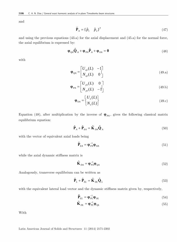
Q , P global vectors of nodal displacements and of nodal forces, respectively
EP , DK global vector of the equivalent loads and global dynamic stiffness matrix,
respectively
CM , CK global matrices of the nodal concentrated masses and springs, respectively
1 INTRODUCTION
Many modern structures are formed by beam elements. These skeleton like structures are subjected to static and dynamic loads. Their beam members can be of various sizes, including beams with small length to beam height ratio. For the analysis of these structures, it is important to use a more refined beam theory, where the assumption of the cross section to remain plane is not enforced. Besides, harmonic loads can be of high frequency, when then it is important to keep in the beam model the cooperation of the rotatory inertia to the overall structure response. This motivates the use of the Timoshenko beam theory to obtain the damped steady state response for general plane frames subjected to harmonically time varying external forces.
The study reported here concerns with an exact harmonic analysis using the classical Dynamic Stiffness Matrix, DSM. The problem at hand is non-linear and transcendental with respect to the excitation frequency [Howson and Williams (1973)]. The approach used to solve it is by the use of the Laplace transform.
Focusing on the calculation of natural frequencies, Howson and Williams (2003) present a formulation based on the classical DSM obtained by a set of decoupled fourth order partial differential equations (PDE) for the unknowns deflection and rotation of the beam cross section. Dias and Alves (2009) also derive the DSM via the same procedure but reaches an improved formulation, argued to be more suitable for the eigenproblem solution. It has been noticed [Schanz and Antes (2002)] that the dynamic analyses of beams can be performed by decoupling deflection and rotation. In the study described here, the original coupled PDEs, combining deflection, rotation, bending moment and shear force, are directly employed in order to reach the DSM formulation as well as the formulation for the equivalent load vector that arises due to distributed loads on the beams and frames.
We remark that, to be considered exact, a solution must adopt no assumptions other than those of the beam theory itself. Hence, if the mode superposition method is employed, the result is not exact once it is affected by series truncation error. For this reason, many good publications
2174 C. A. N. Dias / General exact harmonic analysis of in-plane Timoshenko beam structures
Latin American Journal of Solids and Structures 11 (2014) 2171-2202
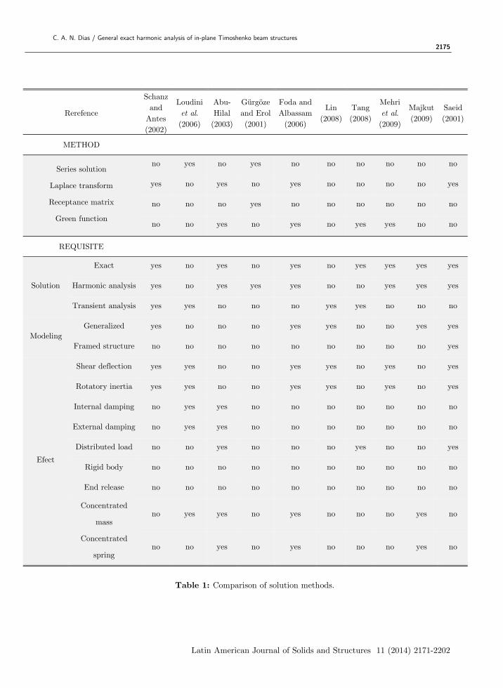
dedicated to dynamic frame response calculation do not conform to the requirements of an exact solution and therefore are not considered here. Concerning the dynamic response of frames, Table 1 compares different solution methods found in the literature [Abu-Hilal (2003), Foda and Albassam (2006), Gürgöze and Erol (2001), Lin (2008), Loudini et. al. (2006), Majukt (2009), Mehri et. al. (2009), Saeid (2011), Schanz and Antes (2002), Tang (2008)]. In the present context, it is imperative that the PDE representing the governing equations of a given in-plane structure subjected to harmonic forces has to be solved exactly. This can be achieved by using Laplace transform [Abu-Hilal (2003), Foda and Albassam (2006), Loudini et. al. (2006), Saeid (2011)] and/or Green functions [Abu-Hilal (2003), Tang (2008), Davar and Rahmani (2009)]. Gürgöze and Erol (2001) use a distinct method based on a receptance matrix but cannot be considered exact since series solution is employed.
As seen in Table 1, only the solutions given in (Shanz and Antes, 2002; Foda and Albassam, 2006; Lin, 2008; Majkut, 2009; Saeid, 2001) could be generalized in order to solve models of arbitrary numbers of beams and boundary conditions. If further features are to be considered, e.g. concentrated masses and springs, these solutions would be limited to the ones developed in (Foda and Albassam, 2006; Majkut, 2009). Even so, these references are dedicated to solve single and/or in-line beams. When considering the capability to solve framed structures with the features of concentrated masses and springs and rigid bodies attached to the members ends, only Seeid (2001) can be highlighted. These features are not taken into account by Antes et al. (2004), which also deals with harmonic loads applied to Timoshenko frames. Mei (2008, 2012) present an interesting model that considers in-plane vibration of some restricted forms of frames. The analyses presented in these references are developed, as here, along the Timoshenko bending theory. In contrast, the present paper is more general inasmuch as it handles any shape of portal planar frame subjected to harmonic loads and it solves the equations of motion via the Laplace transform.
Except for the case of transient analysis, which is beyond the scope of this study, the solution of the present investigation is unique in the sense that attends to all of the requisites listed in Table 1. Indeed, to best of the author knowledge, no other publication in the context of harmonic analysis pays attention to effects like rigid offset and end release. Few publications (Abu-Hilal, 2003; Tang, 2008; Saeid, 2001) have considered distributed loads and even fewer have incorporated damping (Loudini, 2006; Abu-Hilal, 2003) in their analysis.
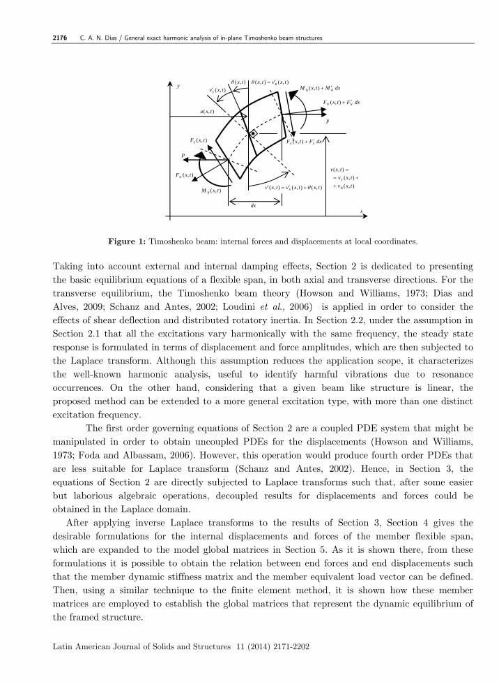
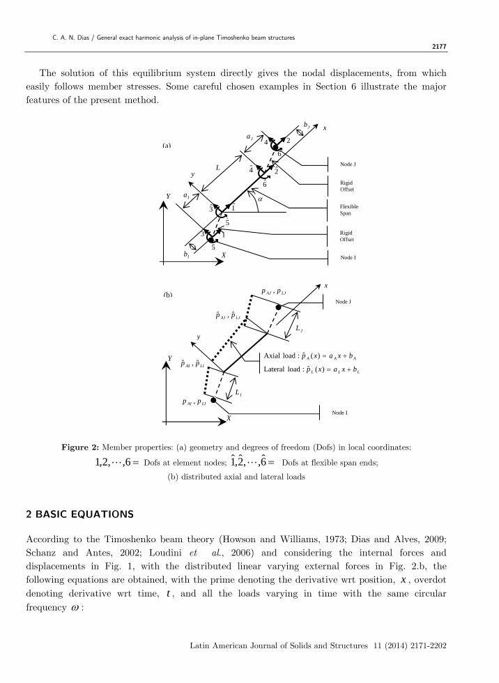
The framed structure under consideration is composed by in-plane members, which are connected to each other through previously defined nodes. Each member has a flexible span, which obeys the Timoshenko beam theory, and may also have rigid bodies attached to its ends, where forces can be released. Fig. 1 depicts the internal forces and displacements for the flexible span, while Fig. 2 shows the end forces, end displacements, distributed loads, and attached rigid bodies for a typical member. Since the rigid bodies may or may not have mass, herein they are alternatively named rigid offsets.
C. A. N. Dias / General exact harmonic analysis of in-plane Timoshenko beam structures 2175
Latin American Journal of Solids and Structures 11 (2014) 2171-2202
Rerefence
Schanz and
Antes (2002)
Loudini et al. (2006)
Abu-Hilal (2003)
Gürgöze and Erol (2001)
Foda and Albassam
(2006)
Lin (2008)
Tang (2008)
Mehri et al. (2009)
Majkut (2009)
Saeid (2001)
METHOD
Series solution
Laplace transform
Receptance matrix
Green function
no yes no yes no no no no no no
yes no yes no yes no no no no yes
no no no yes no no no no no no
no no yes no yes no yes yes no no
REQUISITE
Solution
Exact yes no yes no yes no yes yes yes yes
Harmonic analysis yes no yes yes yes no no yes yes yes
Transient analysis yes yes no no no yes yes no no no
Modeling Generalized yes no no no yes yes no no yes yes
Framed structure no no no no no no no no no yes
Efect
Shear deflection yes yes no no yes yes no yes no yes
Rotatory inertia yes yes no no yes yes no yes no yes
Internal damping no yes yes no no no no no no no
External damping no yes yes no no no no no no no
Distributed load no no yes no no no yes no no yes
Rigid body no no no no no no no no no no
End release no no no no no no no no no no
Concentrated
mass no yes yes no yes no no no yes no
Concentrated
spring no no yes no yes no no no yes no
Table 1: Comparison of solution methods.
2176 C. A. N. Dias / General exact harmonic analysis of in-plane Timoshenko beam structures
Latin American Journal of Solids and Structures 11 (2014) 2171-2202
Figure 1: Timoshenko beam: internal forces and displacements at local coordinates.
Taking into account external and internal damping effects, Section 2 is dedicated to presenting the basic equilibrium equations of a flexible span, in both axial and transverse directions. For the transverse equilibrium, the Timoshenko beam theory (Howson and Williams, 1973; Dias and Alves, 2009; Schanz and Antes, 2002; Loudini et al., 2006) is applied in order to consider the effects of shear deflection and distributed rotatory inertia. In Section 2.2, under the assumption in Section 2.1 that all the excitations vary harmonically with the same frequency, the steady state response is formulated in terms of displacement and force amplitudes, which are then subjected to the Laplace transform. Although this assumption reduces the application scope, it characterizes the well-known harmonic analysis, useful to identify harmful vibrations due to resonance occurrences. On the other hand, considering that a given beam like structure is linear, the proposed method can be extended to a more general excitation type, with more than one distinct excitation frequency.
The first order governing equations of Section 2 are a coupled PDE system that might be manipulated in order to obtain uncoupled PDEs for the displacements (Howson and Williams, 1973; Foda and Albassam, 2006). However, this operation would produce fourth order PDEs that are less suitable for Laplace transform (Schanz and Antes, 2002). Hence, in Section 3, the equations of Section 2 are directly subjected to Laplace transforms such that, after some easier but laborious algebraic operations, decoupled results for displacements and forces could be obtained in the Laplace domain. After applying inverse Laplace transforms to the results of Section 3, Section 4 gives the desirable formulations for the internal displacements and forces of the member flexible span, which are expanded to the model global matrices in Section 5. As it is shown there, from these formulations it is possible to obtain the relation between end forces and end displacements such that the member dynamic stiffness matrix and the member equivalent load vector can be defined. Then, using a similar technique to the finite element method, it is shown how these member matrices are employed to establish the global matrices that represent the dynamic equilibrium of the framed structure.
P
dx
),( tx),( txvS
dxFtxF NN ),(
P
dxFtxF SS ),(
dxMtxM BB ),(
),( txFN
),( txFS
),( txM B
x
y
),(
),(
),(
txv
txv
txv
B
S
),(),(),( txtxvtxv S
),(),( txvtx B
),( txu
C. A. N. Dias / General exact harmonic analysis of in-plane Timoshenko beam structures 2177
Latin American Journal of Solids and Structures 11 (2014) 2171-2202
The solution of this equilibrium system directly gives the nodal displacements, from which easily follows member stresses. Some careful chosen examples in Section 6 illustrate the major features of the present method.
Figure 2: Member properties: (a) geometry and degrees of freedom (Dofs) in local coordinates:
6,,2,1 Dofs at element nodes; 6̂,,2̂,1̂ Dofs at flexible span ends;
(b) distributed axial and lateral loads
2 BASIC EQUATIONS
According to the Timoshenko beam theory (Howson and Williams, 1973; Dias and Alves, 2009; Schanz and Antes, 2002; Loudini et al., 2006) and considering the internal forces and displacements in Fig. 1, with the distributed linear varying external forces in Fig. 2.b, the following equations are obtained, with the prime denoting the derivative wrt position, x , overdot denoting derivative wrt time, t , and all the loads varying in time with the same circular frequency :
Jb
yL
Ja
Ia
Ib
x
1
2
3
4
5
6
1̂
2̂
3̂
4̂
5
6̂
Node I
Node J
Flexible Span
Rigid Offset
Rigid Offset
X
Y
LJAJ pp ˆ,ˆ
y
X
Y
x
Node I
Node J
LIAI pp ,
LIAI pp ˆ,ˆ
IL
JL
LJAJ pp ,
AAA bxaxp )(ˆ : load Axial
LLL bxaxp )(ˆ : load Lateral
(a)
(b)
2178 C. A. N. Dias / General exact harmonic analysis of in-plane Timoshenko beam structures
Latin American Journal of Solids and Structures 11 (2014) 2171-2202
Normal stress, σN
( , ) [ ( , ) ( , )]N Ix t E u x t c u x ts ¢ ¢= + (1)
Normal force, FN
( , ) ( , ) [ ( , ) ( , )]N N IF x t A x t EA u x t c u x ts ¢ ¢= = + (2)
Axial equilibrium
tjAAEN ebxatxumctxumtxF )(),(),(),( (3)
Mean shear stress, τ
( , ) [ ( , ) ( , )]S I Sx t G v x t c v x tt ¢ ¢= - + (4)
Shear force, FS
( , ) ( , ) ( , ) [ ( , ) ( , )] ( , )
[ ( , ) ( , )] [ ( , ) ( , )]S S S S I S
S I S I
F x t A x t Pv x t GA v x t c v x t Pv x t
GA x t c x t GA v x t c v v x t
(5)
Transverse force equilibrium
tjLLES ebxatxvmctxvmtxF )(),(),(),( (6)
Bending stress, σB
),(),([))],(),([ ),,( txctxyEtxvctxvyEtyx IBIBB (7)
Bending moment, MB
( , ) ( , ) [ ( , ) ( , )]B B IM x t y x t dA EI x t c x ts q q¢ ¢= = +ò (8)
Moment equilibrium
),(),(),(),(),(),(),( txrtxvPtxFtxvrtxvPtxFtxM SBSB (9)
Here, E and G are the elastic and shear moduli, u and v are the axial and total transverse beam displacement, vs is the transverse displacement due to shear, A and As are the total cross-section and shear areas, aA and aL are the slope of the distributed axial and transverse load, bA and bL are the distributed axial and transverse load, m is the mass per unit length, p and P are distributed axial loads.
C. A. N. Dias / General exact harmonic analysis of in-plane Timoshenko beam structures 2179
Latin American Journal of Solids and Structures 11 (2014) 2171-2202
In these equations, the internal and external damping coefficients, Ic and Ec , respectively,
are defined in order to reproduce the Rayleigh formulation, where Ec represents the mass
proportional coefficient and Ic the stiffness proportional coefficient. From this, by using the
orthogonal condition of the natural modes, it is possible to establish the following expression for the modal damping ratio i :
2/)/( iIiEi cc (10)
Meaningful values for Ic and Ec can be obtained whenever a pair of modal damping ratio values
is known. Therefore, after applying Eq. (10), these damping coefficients can be computed by:
)/()(2 21
22122121 Ec (11.a)
)/()(2 21
221122 Ic
(11.b)
where the natural frequencies ( 21 , ) and the damping ratios ( 21 , ), for the lowest first and
second modes, are supposedly known. On the other hand, by imposing that both Rayleigh damping coefficients must be non-negative
and that the peak frequencies pi given by:
221 iipi (12)
must be real, the following restrictions must be obeyed:
)/()/( 1212211 (13.a)
0.707 /22, 21 (13.b)
The external damping coefficient Ec accounts for the environment viscous actions expressed by
the forces ),( txuc and ),( txvc , so that:
1[ ]Ec
c sm
- = (14.a)
The internal damping coefficient Ic accounts for the energy dissipation due to the structure
deformation rate and can be related with the Kelvin-Voight damping coefficient VK (Shanz and
Antes, 2002):
EKsc VI /][ (14.b)
A more complete characterization of damping in dynamic structural systems can be found in Oliveto, and Greco (2002), where it is shown that the Rayleigh coefficients are independent of the boundary conditions, no matter whether the system is continuous or discrete.
2180 C. A. N. Dias / General exact harmonic analysis of in-plane Timoshenko beam structures
Latin American Journal of Solids and Structures 11 (2014) 2171-2202
2.1 Steady state response
For the steady state response, all the previous defined internal forces and displacements can be written according to the general equation
tjexFtxF )(),( (15)
with time and space being decoupled. Performing time derivatives in equations (1-9), the amplitudes are related by:
)()1( )( xujcEAxF IN (16.a)
)()()()( 2AAEN bxaxujcmxF (16.b)
)(])1( [)()1( )( xvPjcGAxjcGAxF ISISS (16.c)
)()()()( 2LLES bxaxvjcmxF (16.d)
)()1( )( xjcEIxM IB (16.e)
)()()()( 2 xrxvPxFxM SB (16.f)
where, for instance, ( )v x , is the amplitude of the beam total deflection.
2.2 Laplace Transform
Applying the Laplace transform over the previous defined amplitudes:
0
( ) [ ( )[( )] ( ) sxF s F x s F x e dxl¥
= = ò (17)
the differential equations (16) are substituted by the following simple algebraic expressions:
)]0()(~)[1( )(~
ususjcEAsF IN (18.a)
sbsasujcmFsFs AAEN //)(~)()0()(~ 22 (18.b)
)]0()(~][)1( [)(~
)1( )(~
vsvsPjcGAsjcGAsF ISISS (18.c)
sbsasvjcmFsFs LLES //)(~)()0()(~ 22 (18.d)
)]0()(~
)[1( )(~ ssjcEIsM IB (18.e)
)(~
)]0()(~[)(~
)0()(~ 2 srvsvsPsFMsMs SBB (18.f)
It is adopted in the sequence, according to Fig. 2.a, the convention for the end forces and end displacements as
1ˆ)0( qu 3ˆ)0( qv 5ˆ)0( q (19.a)

C. A. N. Dias / General exact harmonic analysis of in-plane Timoshenko beam structures 2181
Latin American Journal of Solids and Structures 11 (2014) 2171-2202
1ˆ)0( pFN 3ˆ)0( pFS 5ˆ)0( pM B (19.b)
Now, solving Eqs. (18.a) and (18.b) for the axial displacement results in:
1
20 )(
~)(~
n
nn sAsesu (20)
with
)/(1)(~ 22
0 AssA (21.a)
11 q̂e (21.b)
)]1(/[ˆ1 Io jcEApe (21.c)
)]1(/[1 IA jcEAbe (21.d)
)]1(/[2 IA jcEAae (21.e)
where
)1()/1( IEA jcjcEAm (22)
Total deflection can be obtained after considerable algebraic manipulation of Eqs. (18.c–f), yielding:
3
20 )(
~)(~
n
nn sLsasv (23)
with
)/()/(1)(~ 2
222
12
0 sssL (24.a)
33 q̂a (24.b)
1352 /]/ˆˆ)1[( SI GApqjca (24.c)
)/()(ˆ)/(ˆ)/( 12
031511 EIrPqEIpGAba SL (24.d)
)/(ˆ)/( 10310 EIpGAaa SL (24.e)
)/( 101 EIba L (24.f)
)/( 102 EIaa L (24.g)
when adopting
)]1(/[1 20 IS jcGAr (25.a)
2182 C. A. N. Dias / General exact harmonic analysis of in-plane Timoshenko beam structures
Latin American Journal of Solids and Structures 11 (2014) 2171-2202
SI GAPwjc /11 (25.b)
2/1323
2112,1 )}2/(]4{[ hhhhh (25.c)
and
EIh 13 (26.a)2
02
1 /)/1( rPGAmjcEIh SE (26.b)2
02 )/1( mjch E (26.c)
Analogously, solving Eqs. 16(c-f) for the shear force and bending rotation results in:
2
3013
23 )(~
/ˆ//)(~
n
nnLL sLsaspsbsasF (27)
2
30132
323
)(~
]ˆ)(~[
)]1(/[]/ˆ//[)(~
n
nn
ISLL
sLsaqsvs
jcGAspsbsas
(28)
with )]1(/[)/1(2 ISE jcGAwjcm (29)
The Laplace transform of the bending moment can be obtained by inserting Eq. (28) into Eq.
(18.e). The bending moment amplitude, )(xM B , comes from Eq. (16.e) once the rotation
amplitude, )(x , has been obtained.
A common practice in the specialized literature is to decouple Eqs. (16) in order to obtain a set of differential equations involving only one unknown function. For the Timoshenko theory, complicated terms involving fourth order derivatives will appear, so the use of the Laplace transform is troublesome. To avoid this, here the Laplace transform was directly applied to the coupled first order Eqs. (16) by applying the transform to second order coupled equations involving only deflection and rotation. As a remark, Schanz and Antes (2002) also avoids to work with fourth order derivatives.
3 INVERSE LAPLACE TRANSFORM
By applying the inverse transform to Eq. (20) for the axial displacement and then using the result in Eq. (16.a) for the normal force, these corresponding amplitudes are then given, respectively, by:
1
2
)()(n
nn xAexu (30)
C. A. N. Dias / General exact harmonic analysis of in-plane Timoshenko beam structures 2183
Latin American Journal of Solids and Structures 11 (2014) 2171-2202
1
21
1
2
)()1()()1()(n
nnEn
nnEN xAejcEAxAejcEAxF (31)
where, knowing that
)()( 1 xAxA nn for 0n (32.a)
and
x
nn dAxA0
1 )()( for 0n (32.b)
it holds that 1. For .....6,4,2,0n
)()1()( 12/ xsinxA AnA
nn (33.a)
2. For .....5,4,3,1n
)cos()1()( 12/)1( xxA AnA
nn (33.b)
3. For ,6,4,2 n
( 2)/2/2 1 2 1 2
0
( ) ( 1) [ sin( ) ( 1) / (2 1)!]n
n n k k n kn A A A
k
A x x x kb b b- +
- + +
=
= - - - +å (33.c)
4. For ,4,3,1 n
( 1)/2(1 )/2 1 2 2 1
0
( ) ( 1) [ cos( ) ( 1) / 2 !]n
n n k k n kn A A A
k
A x x x kb b b- +
- - + -
=
= - - -å (33.d)
As for the total deflection, it can be obtained by applying the inverse transform to Eq. (23), yielding
3
2
)()(n
nn xLaxv (34)
where
)()( 1 xLxL nn for 0n (35.a)
and
x
nn dLxL0
1 )()( for 0n (35.b)
2184 C. A. N. Dias / General exact harmonic analysis of in-plane Timoshenko beam structures
Latin American Journal of Solids and Structures 11 (2014) 2171-2202
with
1. For ,6,4,2,0n
]/[)]()([)( 22
212
121
11 xsinhxsinhxL nn
n (36.a)
2. For ,7,5,3,1n
]/[)]cosh()cosh([)( 22
212
121
11 xxxL nn
n (36.b)
3. For ,6,4,2 n
]/[})!12/()(
)()({)(
22
21
2/)2(
0
22
21
)12(
21
211
1
n
k
knknk
nnn
kx
xsinhxsinhxL
(36.c)
4. For ,5,3,1 n
]/[}!2/)(
)cosh()cosh({)(
22
21
2/)1(
0
122
121
2
21
211
1
n
k
knknk
nnn
kx
xxxL
(36.d)
The rotation due to bending is obtained by substituting Eq. (23) into Eq. (28) and applying the inverse transform so that the amplitude is:
4
3
23 )()]1(/[)2/ˆ()(
nnnISLL xLbjcGAxbxapx for 0n (37)
With
324 q̂b (38,a)
123 ab (38.b)
1232 ˆ aqb (38.c)
0221 aab (38.d)
1210 aab (38.e)
2201 aab (38.f)
12 ab (38.g)
23 ab (38.h)
and
)]1(/[12 IS jcGAP (39)
C. A. N. Dias / General exact harmonic analysis of in-plane Timoshenko beam structures 2185
Latin American Journal of Solids and Structures 11 (2014) 2171-2202
Finally, the shear force amplitudes come from the inverse transform of Eq. (27), resulting in
2
31
223 )()/1(2/ˆ)(
nnnELLS xLawjcmxbxapxF (40)
while the bending moment amplitude comes from the use of Eq. (37) in expression (16.e),
4
31 )()1()/()(
)()1()(
nnnISLL
IB
xLbjcEIGAbxaEI
xwjcEIxM
(41)
4 MEMBER MATRICES
4.1 Flexible span equilibrium
Applying the following boundary conditions for the end displacement (see Fig. 2.a):
2ˆ)( qLu 4ˆ)( qLv 6ˆ)( qL (42)
after laborious algebraic work, the equations of the previous section can be rearranged in the following expressions for the internal displacements:
)(ˆ)(ˆ)()( 1111 xUpxUqxUxu opq (43.a)
)(ˆ)(ˆ)(ˆ)(ˆ)()( 55335533 xVpxVpxVqxVqxVxv oppqq (43.b)
)(ˆ)(ˆ)(ˆ)(ˆ)()( 55335533 xpxpxqxqxx oppqq (43.c)
with the functions on the right hand sides (from )(1 xU q to )(xo ) being defined in Appendix A.
Analogously, applying the following boundary conditions for the end forces:
2ˆ)( pLFN 4)( pLFS
6ˆ)( pLM B (44)
the internal forces are given by:
)(ˆ)(ˆ)()( 1111 xNpxNqxNxF opqN (45.a)
)(ˆ)(ˆ)(ˆ)(ˆ)()( 55335533 xSpxSpxSqxSqxSxF oppqqS (45.b)
)(ˆ)(ˆ)(ˆ)(ˆ)()( 55335533 xBpxBpxBqxBqxBxM oppqqB (45.c)
with the functions on the right hand sides (from )(1 xNq to )(xBo ) being defined in Appendix A.
Now, defining the vectors:
TA qq }ˆˆ{ˆ
21Q (46)
2186 C. A. N. Dias / General exact harmonic analysis of in-plane Timoshenko beam structures
Latin American Journal of Solids and Structures 11 (2014) 2171-2202
and
TA pp }ˆˆ{ˆ
21P (47)
and using the previous equations (43.a) for the axial displacement and (45.a) for the normal force, the axial equilibrium is expressed by:
0φPφQφ OAAPAAQAˆˆ (48)
with
0)(
1)(
1
1
LN
LU
q
qQAφ (49.a)
1)(
0)(
1
1
LN
LU
p
pPAφ (49.b)
)(
)(
LN
LU
o
oOAφ (49.c)
Equation (48), after multiplication by the inverse of PAφ , gives the following classical matrix
equilibrium equation:
ADAEAA QKPP ˆˆˆˆ (50)
with the vector of equivalent axial loads being
OAPAEA φφP 1ˆ (51)
while the axial dynamic stiffness matrix is
QAPADA φφK 1ˆ (52)
Analogously, transverse equilibrium can be written as
LDLELL QKPP ˆˆˆˆ (53)
with the equivalent lateral load vector and the dynamic stiffness matrix given by, respectively,
OLPLEL φφP 1ˆ (54)
QLPLDL φφK 1ˆ (55)
With

C. A. N. Dias / General exact harmonic analysis of in-plane Timoshenko beam structures 2187
Latin American Journal of Solids and Structures 11 (2014) 2171-2202
TL qqqq }ˆˆˆˆ{ˆ
6543Q (56)
TL pppp }ˆˆˆˆ{ˆ
6543P (57)
0)(0)(
0)(0)(
1)(0)(
0)(1)(
53
53
53
53
LSLS
LBLB
LL
LVLV
QL
φ (58.a)
0)(1)(
1)(0)(
0)(0)(
0)(0)(
53
53
53
53
LSLS
LBLB
LL
LVLV
pp
pp
pp
pp
PL
φ (58.b)
)(
)(
)(
)(
LS
LB
L
LV
o
o
o
o
OL
φ (58.c)
Now, combining both axial and lateral matrix equilibrium equations, it follows that:
QKPP ˆˆˆˆDE (59)
with the end displacements and end forces vectors being given, respectively, by
Tqqqqqq }ˆˆˆˆˆˆ{ˆ654321Q (60)
Tpppppp }ˆˆˆˆˆˆ{ˆ654321P (61)
The equivalent load vector is
EL
EAE
P
PP
ˆ
ˆˆ (62)
and the dynamic stiffness matrix is
DL
DAD
K0
0KK
ˆ
ˆˆ (63)
2188 C. A. N. Dias / General exact harmonic analysis of in-plane Timoshenko beam structures
Latin American Journal of Solids and Structures 11 (2014) 2171-2202
4.2 Rigid offset
Observing Fig. 2, the conversions from the flexible span ends to the member ends are given by:
QTQ ˆQ (64)
QSPPTP ˆˆ 2QRQ (65)
where
100000
010000
01000
00100
00010
00001
J
I
J
I
Q a
a
b
b
T (66.a)
3/ˆ6/
3/ˆ6/
2/)ˆ(
2/)ˆ(
2/)ˆ(
2/)ˆ(
00000
00000
0000
0000
0000
0000
2
2
LJLJ
LILI
LJLJ
AJAJ
LILI
AIAI
J
I
JJ
II
JJ
II
R
pp
pp
pp
pp
pp
pp
L
L
ab
ab
ba
ba
P (66.b)
1000
0100
001000
000100
000010
000001
JJ
II
P
ab
ab
T (66.c)
][ ITHJUS QQ (66.d)
with
][diag RJTJTJRITITI MMMMMMJ (67.a)
and
C. A. N. Dias / General exact harmonic analysis of in-plane Timoshenko beam structures 2189
Latin American Journal of Solids and Structures 11 (2014) 2171-2202
100000
001000
000010
010000
000100
000001
5.0U (67.b)
12/2/000
00012/2/
010000
000010
001000
000001
JJ
II
ab
ab
H (67.c)
AIAIAJTIAI pppLLp ))((ˆ (67.d)
LILILJTILI pppLLp ))((ˆ (67.e)
AIAIAJTIAJ pppLLLp )](/)[(ˆ (67.f)
LILILJTILJ pppLLLp )](/)[(ˆ (67.g)
22III baL (67.h)
22JJJ baL (67.i)
JIT LLLL (67.j)
Now, collecting P̂ and Q̂ from expressions (64, 65) and substituting into Eq. (59), member
equilibrium requires that:
QKPP DE (68)
where, for the member equivalent load vector and the member dynamic stiffness matrix, respectively, we have:
REPE PPTP ˆ (69) 12 )ˆ( QQDPD TSKTK (70)
2190 C. A. N. Dias / General exact harmonic analysis of in-plane Timoshenko beam structures
Latin American Journal of Solids and Structures 11 (2014) 2171-2202
4.3 End force release
Let PI denote a permutation matrix that moves, to the last line, the degree of freedom to be
released. If, for any end displacement vector Q , it is imposed that the corresponding end force
must be null, it can be written that:
b
aP
Q~
~~ Q
QIQ (71)
0~
~~
b
aP
P
PPIP (72)
Eb
EaEPE
P~
~~ P
PIP (73)
By doing so, the released versions for the member equivalent load vector and for the member dynamic stiffness matrix are, respectively:
0
~/
~~~bbEbabEaT
PE
KPKPIP (74)
PbbbaabaaT
PD
KI
0
0KKKIK
0
~/
~~~ (75)
with the partitions EaP~
, EbP~
, aaK~
, abK~
, baK~
and bbK~
coming from:
Eb
EaEP
P~
~P
PI (76)
bbba
abaaTPDP
K~~
~~
K
KKIKI (77)
Finally, the displacement of the released degree of freedom can be obtained from:
bbabaEbb KPQ~
/)~~~
(~
QK (78)
C. A. N. Dias / General exact harmonic analysis of in-plane Timoshenko beam structures 2191
Latin American Journal of Solids and Structures 11 (2014) 2171-2202
5 MODEL GLOBAL MATRICES
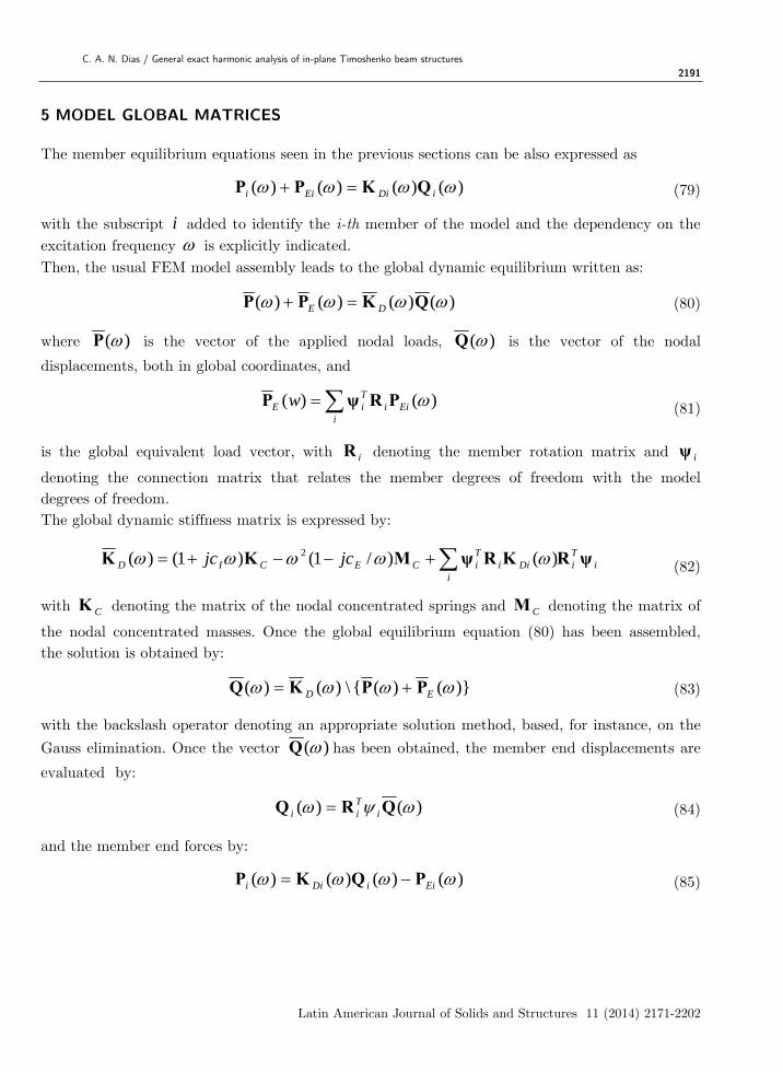
The member equilibrium equations seen in the previous sections can be also expressed as
)()()()( iDiEii QKPP (79)
with the subscript i added to identify the i-th member of the model and the dependency on the excitation frequency is explicitly indicated. Then, the usual FEM model assembly leads to the global dynamic equilibrium written as:
)()()()( QKPP DE (80)
where )(P is the vector of the applied nodal loads, )(Q is the vector of the nodal
displacements, both in global coordinates, and
i
EiiTiE w )()( PRψP (81)
is the global equivalent load vector, with iR denoting the member rotation matrix and iψ
denoting the connection matrix that relates the member degrees of freedom with the model degrees of freedom. The global dynamic stiffness matrix is expressed by:
iTi
iDii
TiCECID jcjc ψRKRψMKK )()/1()1()( 2 (82)
with CK denoting the matrix of the nodal concentrated springs and CM denoting the matrix of
the nodal concentrated masses. Once the global equilibrium equation (80) has been assembled, the solution is obtained by:
)}()({\)()( ED PPKQ (83)
with the backslash operator denoting an appropriate solution method, based, for instance, on the
Gauss elimination. Once the vector )(Q has been obtained, the member end displacements are
evaluated by:
)()( QRQ iTii (84)
and the member end forces by:
)()()()( EiiDii PQKP (85)
2192 C. A. N. Dias / General exact harmonic analysis of in-plane Timoshenko beam structures
Latin American Journal of Solids and Structures 11 (2014) 2171-2202
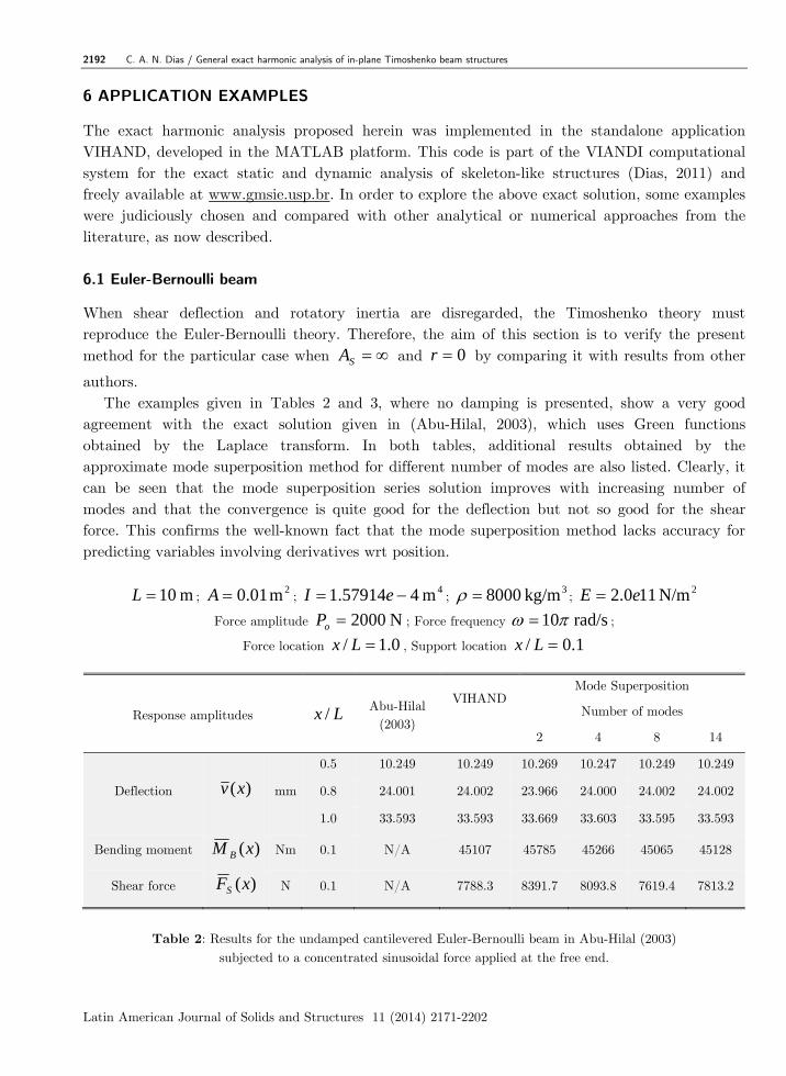
6 APPLICATION EXAMPLES
The exact harmonic analysis proposed herein was implemented in the standalone application VIHAND, developed in the MATLAB platform. This code is part of the VIANDI computational system for the exact static and dynamic analysis of skeleton-like structures (Dias, 2011) and freely available at www.gmsie.usp.br. In order to explore the above exact solution, some examples were judiciously chosen and compared with other analytical or numerical approaches from the literature, as now described. 6.1 Euler-Bernoulli beam
When shear deflection and rotatory inertia are disregarded, the Timoshenko theory must reproduce the Euler-Bernoulli theory. Therefore, the aim of this section is to verify the present method for the particular case when SA and 0r by comparing it with results from other
authors. The examples given in Tables 2 and 3, where no damping is presented, show a very good
agreement with the exact solution given in (Abu-Hilal, 2003), which uses Green functions obtained by the Laplace transform. In both tables, additional results obtained by the approximate mode superposition method for different number of modes are also listed. Clearly, it can be seen that the mode superposition series solution improves with increasing number of modes and that the convergence is quite good for the deflection but not so good for the shear force. This confirms the well-known fact that the mode superposition method lacks accuracy for predicting variables involving derivatives wrt position.
m 10L ; 2m 01.0A ;
4m 457914.1 eI ; 3kg/m 8000 ;
2N/m 110.2 eE
Force amplitude N 2000oP ; Force frequency rad/s 10 ;
Force location 0.1/ Lx , Support location 1.0/ Lx
Response amplitudes Lx / Abu-Hilal
(2003)
VIHAND Mode Superposition
Number of modes
2 4 8 14
Deflection )(xv mm
0.5 10.249 10.249 10.269 10.247 10.249 10.249
0.8 24.001 24.002 23.966 24.000 24.002 24.002
1.0 33.593 33.593 33.669 33.603 33.595 33.593
Bending moment )(xM B Nm 0.1 N/A 45107 45785 45266 45065 45128
Shear force )(xFS N 0.1 N/A 7788.3 8391.7 8093.8 7619.4 7813.2
Table 2: Results for the undamped cantilevered Euler-Bernoulli beam in Abu-Hilal (2003) subjected to a concentrated sinusoidal force applied at the free end.
C. A. N. Dias / General exact harmonic analysis of in-plane Timoshenko beam structures 2193
Latin American Journal of Solids and Structures 11 (2014) 2171-2202
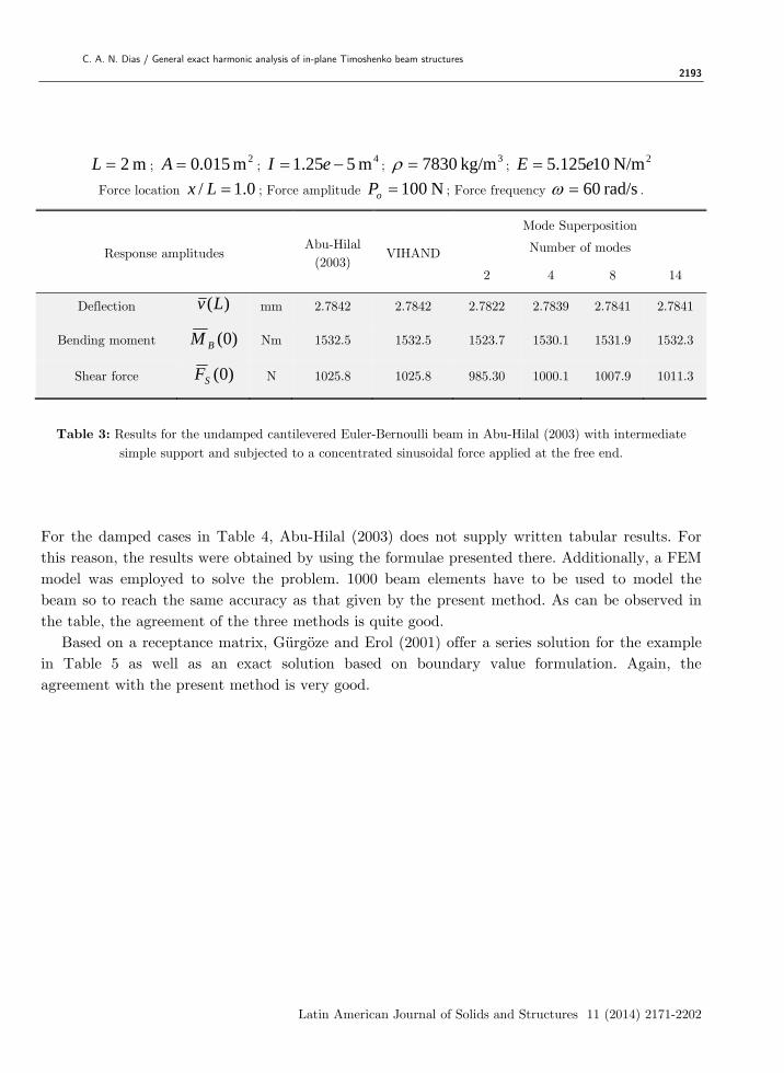
m 2L ; 2m 015.0A ;
4m 525.1 eI ; 3kg/m 7830 ;
2N/m 10125.5 eE
Force location 0.1/ Lx ; Force amplitude N 100oP ; Force frequency rad/s 60 .
Response amplitudes Abu-Hilal
(2003) VIHAND
Mode Superposition
Number of modes
2 4 8 14
Deflection )(Lv mm 2.7842 2.7842 2.7822 2.7839 2.7841 2.7841
Bending moment )0(BM Nm 1532.5 1532.5 1523.7 1530.1 1531.9 1532.3
Shear force )0(SF N 1025.8 1025.8 985.30 1000.1 1007.9 1011.3
Table 3: Results for the undamped cantilevered Euler-Bernoulli beam in Abu-Hilal (2003) with intermediate simple support and subjected to a concentrated sinusoidal force applied at the free end.
For the damped cases in Table 4, Abu-Hilal (2003) does not supply written tabular results. For this reason, the results were obtained by using the formulae presented there. Additionally, a FEM model was employed to solve the problem. 1000 beam elements have to be used to model the beam so to reach the same accuracy as that given by the present method. As can be observed in the table, the agreement of the three methods is quite good.
Based on a receptance matrix, Gürgöze and Erol (2001) offer a series solution for the example in Table 5 as well as an exact solution based on boundary value formulation. Again, the agreement with the present method is very good.
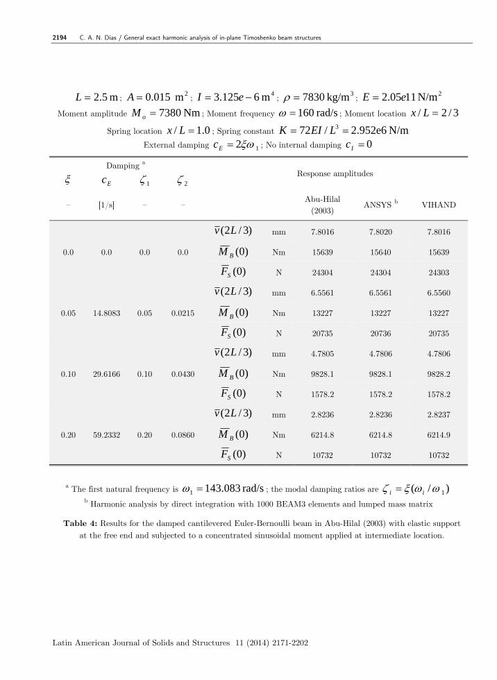
2194 C. A. N. Dias / General exact harmonic analysis of in-plane Timoshenko beam structures
Latin American Journal of Solids and Structures 11 (2014) 2171-2202
Table 4: Results for the damped cantilevered Euler-Bernoulli beam in Abu-Hilal (2003) with elastic support at the free end and subjected to a concentrated sinusoidal moment applied at intermediate location.
m 5.2L ; 2m 015.0A ;
4m 6125.3 eI ; 3kg/m 7830 ;
2N/m 1105.2 eE
Moment amplitude Nm 7380oM ; Moment frequency rad/s 160 ; Moment location 3/2/ Lx
Spring location 0.1/ Lx ; Spring constant N/m 2.952e6 /72 3 LEIK
External damping 1 2 Ec ; No internal damping 0 Ic
Damping a Response amplitudes Ec 1 2
– [1/s] – – Abu-Hilal
(2003) ANSYS b VIHAND
0.0 0.0 0.0 0.0
)3/2( Lv mm 7.8016 7.8020 7.8016
)0(BM Nm 15639 15640 15639
)0(SF N 24304 24304 24303
0.05 14.8083 0.05 0.0215
)3/2( Lv mm 6.5561 6.5561 6.5560
)0(BM Nm 13227 13227 13227
)0(SF N 20735 20736 20735
0.10 29.6166 0.10 0.0430
)3/2( Lv mm 4.7805 4.7806 4.7806
)0(BM Nm 9828.1 9828.1 9828.2
)0(SF N 1578.2 1578.2 1578.2
0.20 59.2332 0.20 0.0860
)3/2( Lv mm 2.8236 2.8236 2.8237
)0(BM Nm 6214.8 6214.8 6214.9
)0(SF N 10732 10732 10732
a The first natural frequency is rad/s 083.1431 ; the modal damping ratios are )/( 1 ii b Harmonic analysis by direct integration with 1000 BEAM3 elements and lumped mass matrix
C. A. N. Dias / General exact harmonic analysis of in-plane Timoshenko beam structures 2195
Latin American Journal of Solids and Structures 11 (2014) 2171-2202
m 0.10L ; 2m 04.0A ;
4m 4333.1 eI ; 3kg/m 10000 ;
2N/m 100.12 eE
Force location 0.1/ Lx ; Force amplitude N 16000oP ; Force frequency rad/s 10 .
Dimensionless deflection amplitudes 3( ) / ( )ov x EI L P
Support location 3.0/ Lx 5.0/ Lx 7.0/ Lx
Position Lx /
Foda and Albassam
(2006) VIHAND
Foda and Albassam
(2006) VIHAND
Foda and Albassam
(2006) VIHAND
0.2 0.008213 0.008214 0.004138 0.004136 0.002351 0.002351
0.4 0.02999 0.03003 0.005503 0.005501 0.005621 0.005608
0.6 0.1458 0.1459 0.01174 0.01175 0.004174 0.004174
0.8 0.3074 0.3077 0.04970 0.04971 0.007070 0.007069
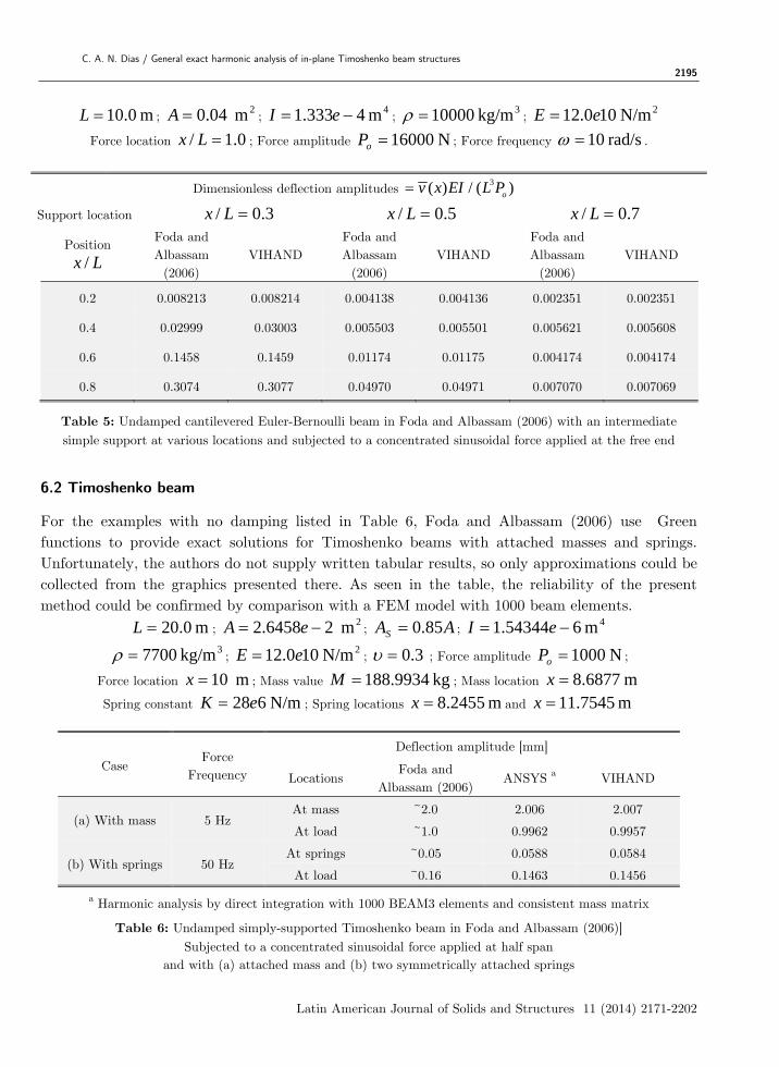
Table 5: Undamped cantilevered Euler-Bernoulli beam in Foda and Albassam (2006) with an intermediate simple support at various locations and subjected to a concentrated sinusoidal force applied at the free end
6.2 Timoshenko beam
For the examples with no damping listed in Table 6, Foda and Albassam (2006) use Green functions to provide exact solutions for Timoshenko beams with attached masses and springs. Unfortunately, the authors do not supply written tabular results, so only approximations could be collected from the graphics presented there. As seen in the table, the reliability of the present method could be confirmed by comparison with a FEM model with 1000 beam elements.
m 0.20L ; 2m 26458.2 eA ; AAS 85.0 ;
4m 654344.1 eI
3kg/m 7700 ; 2N/m 100.12 eE ; 3.0 ; Force amplitude N 1000oP ;
Force location m 10x ; Mass value kg 9934.188M ; Mass location m 6877.8x
Spring constant N/m 628eK ; Spring locations m 2455.8x and m 7545.11x
Case Force
Frequency
Deflection amplitude [mm]
Locations Foda and
Albassam (2006) ANSYS a VIHAND
(a) With mass 5 Hz At mass ~2.0 2.006 2.007
At load ~1.0 0.9962 0.9957
(b) With springs 50 Hz At springs ~0.05 0.0588 0.0584
At load ~0.16 0.1463 0.1456
a Harmonic analysis by direct integration with 1000 BEAM3 elements and consistent mass matrix
Table 6: Undamped simply-supported Timoshenko beam in Foda and Albassam (2006)] Subjected to a concentrated sinusoidal force applied at half span
and with (a) attached mass and (b) two symmetrically attached springs
2196 C. A. N. Dias / General exact harmonic analysis of in-plane Timoshenko beam structures
Latin American Journal of Solids and Structures 11 (2014) 2171-2202
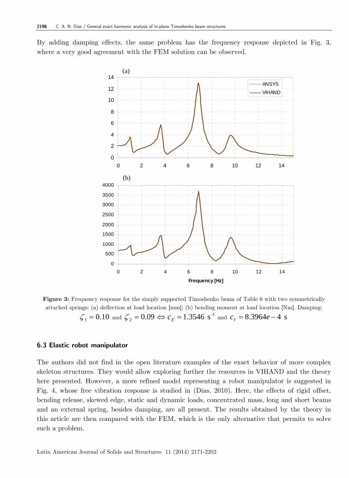
By adding damping effects, the same problem has the frequency response depicted in Fig. 3, where a very good agreement with the FEM solution can be observed.
Figure 3: Frequency response for the simply supported Timoshenko beam of Table 6 with two symmetrically attached springs: (a) deflection at load location [mm]; (b) bending moment at load location [Nm]. Damping:
10.01 and 09.02 -1s 3546.1 Ec and s 43964.8 ecI
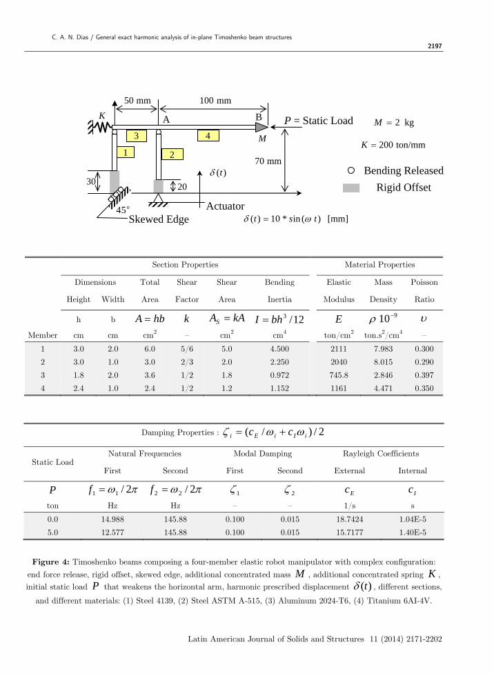
6.3 Elastic robot manipulator
The authors did not find in the open literature examples of the exact behavior of more complex skeleton structures. They would allow exploring further the resources in VIHAND and the theory here presented. However, a more refined model representing a robot manipulator is suggested in Fig. 4, whose free vibration response is studied in (Dias, 2010). Here, the effects of rigid offset, bending release, skewed edge, static and dynamic loads, concentrated mass, long and short beams and an external spring, besides damping, are all present. The results obtained by the theory in this article are then compared with the FEM, which is the only alternative that permits to solve such a problem.
Deflection at Load Position [mm]
0
2
4
6
8
10
12
14
0 2 4 6 8 10 12 14
ANSYS
VIHAND
Bending Moment at Load Position [Nm]
0
500
1000
1500
2000
2500
3000
3500
4000
0 2 4 6 8 10 12 14
Frequency [Hz]
(b)
(a)
C. A. N. Dias / General exact harmonic analysis of in-plane Timoshenko beam structures 2197
Latin American Journal of Solids and Structures 11 (2014) 2171-2202
Section Properties Material Properties
Dimensions Total Shear Shear Bending Elastic Mass Poisson
Height Width Area Factor Area Inertia Modulus Density Ratio
h b hbA k kAAS 12/3bhI E 910
Member cm cm cm2 – cm2 cm4 ton/cm2 ton.s2/cm4 –
1 3.0 2.0 6.0 5/6 5.0 4.500 2111 7.983 0.300
2 3.0 1.0 3.0 2/3 2.0 2.250 2040 8.015 0.290
3 1.8 2.0 3.6 1/2 1.8 0.972 745.8 2.846 0.397
4 2.4 1.0 2.4 1/2 1.2 1.152 1161 4.471 0.350
Damping Properties : 2/)/( iIiEi cc
Static Load Natural Frequencies Modal Damping Rayleigh Coefficients
First Second First Second External Internal
P 2/11 f 2/22 f 1 2 Ec Ic
ton Hz Hz – – 1/s s
0.0 14.988 145.88 0.100 0.015 18.7424 1.04E-5
5.0 12.577 145.88 0.100 0.015 15.7177 1.40E-5
Figure 4: Timoshenko beams composing a four-member elastic robot manipulator with complex configuration:
end force release, rigid offset, skewed edge, additional concentrated mass M , additional concentrated spring K , initial static load P that weakens the horizontal arm, harmonic prescribed displacement )(t , different sections,
and different materials: (1) Steel 4139, (2) Steel ASTM A-515, (3) Aluminum 2024-T6, (4) Titanium 6AI-4V.
Bending Released
Rigid Offset
kg 2M
ton/mm200K
20
[mm] ) (in *10)( tst
mm 70
mm 50 mm 100
)(t
K
Skewed Edge 54 o
P = Static Load
30
1 2
3 4
A B
Actuator
M
2198 C. A. N. Dias / General exact harmonic analysis of in-plane Timoshenko beam structures
Latin American Journal of Solids and Structures 11 (2014) 2171-2202
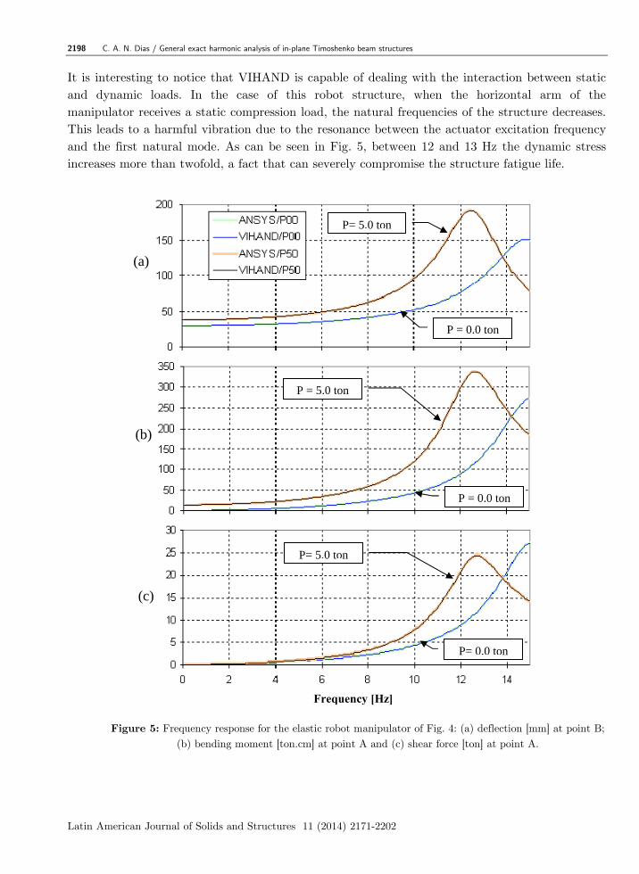
It is interesting to notice that VIHAND is capable of dealing with the interaction between static and dynamic loads. In the case of this robot structure, when the horizontal arm of the manipulator receives a static compression load, the natural frequencies of the structure decreases. This leads to a harmful vibration due to the resonance between the actuator excitation frequency and the first natural mode. As can be seen in Fig. 5, between 12 and 13 Hz the dynamic stress increases more than twofold, a fact that can severely compromise the structure fatigue life.
Figure 5: Frequency response for the elastic robot manipulator of Fig. 4: (a) deflection [mm] at point B; (b) bending moment [ton.cm] at point A and (c) shear force [ton] at point A.
P = 0.0 ton
P= 0.0 ton
P = 0.0 ton
P= 5.0 ton
P= 5.0 ton
P = 5.0 ton
(a)
(c)
(b)
Frequency [Hz]
C. A. N. Dias / General exact harmonic analysis of in-plane Timoshenko beam structures 2199
Latin American Journal of Solids and Structures 11 (2014) 2171-2202
The results of the VIHAND and ANSYS programs agree very well. However, it must be pointed out that the ANSYS model needed more than 240 beam elements to achieve the same accuracy as that obtained by the exact solution of the program VIHAND, which employs only four elements.
Two aspects of the present model are worth considering. First, the method is not suitable for spatial frames analyses, at least in an exact way. The reason is that, for these structures, it is likely that torsion-flexure coupling will be important and torsion is not here taken into account. The consideration of this coupling is far from simple and no attempt was made in the present study to handle it. The second point to highlight is that this model does not intend to be an alternative to the finite element method. But, being possible to obtain an exact solution, it is certain that finite element procedures can benefit from this study inasmuch as the solution procedure here outlined can serve as a reference for this and other numerical procedures.
7 CONCLUSIONS
By applying a Laplace transform to the coupled first order PDEs, which combine displacement and force amplitudes, this work consolidates an exact solution method for the frequency response of in-plane framed structures. The method, based on the Timoshenko beam theory, is quite general since it allows the use of concentrated masses and springs, rigid bodies, end force release, skewed edges, internal damping and external damping as well as concentrated and distributed harmonic loads.
The reliability of the proposed method could be tested by comparing it against simple beam examples found in the literature. The method was also fully verified by means of a more complex model involving the majority of its capabilities and comparing the results with the FEM.
Although a priori developed for a single excitation frequency, the method can be easily extended for more complex and arbitrary time varying excitations by using Fourier series and/or Fourier transform. Hence, the method is useful for spectral analysis implementation in the context of random vibrations.
References
Abu-Hilal M (2003) Forced vibration of Euler-Bernoulli beams by means of dynamic Green functions, Journal of Sound and Vibration, 267: 191–207.
Antes H, Schanz M and Alvermann S (2004) Dynamic analyses of plane frames by integral equations for bars and Timoshenko beams, Journal of Sound and Vibration, 276: 807–836.
Dias CAN and Alves M (2009) A contribution to the exact modal solution of in-plane beam structures, Journal of Sound and Vibration, 328: 586–606.
Dias CAN (2010) Power Secant Method applied to natural frequency extraction of Timoshenko beam structures, Latin American Journal of Solids and Structures, 7: 307-333.
Dias CAN (2011) Computational system for dynamic analysis of in-plane beam structures, ISBN 978-85-900395-0-7, published online at www.gmsie.usp.br.
2200 C. A. N. Dias / General exact harmonic analysis of in-plane Timoshenko beam structures
Latin American Journal of Solids and Structures 11 (2014) 2171-2202
Foda MA and Albassam BA (2006) Vibration confinement in a general beam structure during harmonic excitations, Journal of Sound and Vibration, 295: 491–517.
Gürgöze M and Erol H (2001) Determination of frequency response function of a cantilevered beam simply supported in-span, Journal of Sound and Vibration, 247: 372–378.
Howson WP and Williams FW (1973) Natural frequencies of frames with axially loaded Timoshenko members, Journal of Sound and Vibration, 26: 503–515.
Lin HY (2008) Dynamic analysis of multi-span uniform beam carrying a number of various concentrated elements, Journal of Sound and Vibration, 309: 262–275.
Loudini M, Boukhetala D, Tadjine M and Boumehdi MA (2006) Application of Timoshenko beam theory for deriving motion equations of lightweight elastic link robot manipulator, ICGST-ARAS Journal, 5 II: 11–18.
Majkut L (2009) Free and forced vibrations of Timoshenko beams described by single difference equation, Journal of Theoretical and Applied Mechanics, 47: 193–210.
Mehri B, Davar A and Rahmani O (2009) Dynamic Green function solution of beams under a moving load with different boundary conditions, Mechanical Engineering Transactions, 16: 273–279.
Mei C (2008) Wave analysis of in-plane vibrations of H- and T-shaped planar frame structure, ASME Journal of Vibration and Acoustics, 130: 1-10.
Mei C (2012) Wave Analysis of In-Plane Vibrations of L-Shaped and Portal Planar Frame Structures, ASME Journal of Vibration and Acoustics,134: 1-12.
Oliveto G and Greco A (2002) Some observations on the characterization of structural damping, Journal of Sound and Vibration, 256: 391–415.
Saeid AA (2011) Dynamic stiffness matrix and load functions of Timoshenko beam using the transport matrix, Computers & Structures, 79: 1175–1185.
Schanz M and Antes H (2002) A boundary integral formulation for the dynamic behavior of a Timoshenko beam, Electronic Journal of Boundary Elements, BETEQ 2001, 3: 348–359.
Tang B (2008) Combined dynamic stiffness matrix and precise time integration method for transient forced vibration response analysis of beams, Journal of Sound and Vibration, 309: 868–876.
Appendix A
For the beam flexible span in Fig. 2, the following defines the functions needed to calculate the
internal displacement and force amplitudes by Eqs. (43-45). Function )(xAn is defined by Eqs.
(33) and )(xLn by Eqs. (36).
A.1 Axial displacement
)()( 11 xAxU q
)()]}1(/[1{)( 01 xAjcEAxU Ip
)]1(/[)]()([)( 21 IAAo jcEAxAaxAbxU
C. A. N. Dias / General exact harmonic analysis of in-plane Timoshenko beam structures 2201
Latin American Journal of Solids and Structures 11 (2014) 2171-2202
A.2 Normal force
)()1()( 21 xAjcEAxN Iq
)()( 11 xAxN p
)()()( 10 xAaxAbxN AAo
A.3 Total deflection
)()()( 3331133 xLAxLAxVq
)()()( 0032233 xLAxLAxVp
)()( 2255 xLAxVq
)()( 1155 xLAxVp
)()()()()( 220110000110 xLAxLAxLAxLAxVo
with
133 A )/( 110 SL GAbA
125 /)1( IjcA )/( 1003 EIA
)/(1 123 SGAA )/( 100 SL GAaA
)/()( 12
013 EIrPA )/( 1010 EIbA L
)/(1 115 EIA )/( 1020 EIaA L
)]1(/[1 20 IS jcGAr SI GAPjc /11
A.4 Bending rotation
)()()()( 0032234433 xLBxLBxLBxq
)()()()]1(/[1)( 1131133333 xLBxLBxLBjcGAx ISp
)()()( 1153355 xLBxLBxq
)()()( 0052255 xLBxLBxp
)()()(
)()()(
)]1(/[)2/()(
330220110
000110220
2
xLBxLBxLB
xLBxLBxLB
jcGAxbxax ISLLo
where
243 B 2515 AB 0313 AB
23233 AB 0322313 AAB )/( 1200010 EIaAB L
2202 C. A. N. Dias / General exact harmonic analysis of in-plane Timoshenko beam structures
Latin American Journal of Solids and Structures 11 (2014) 2171-2202
25235 AB 00210 AB )/( 1020 EIbB L
13223 AB 1303 AB )/( 1030 EIaB L
15225 AB 1505 AB
10220 AB )/( 1201000 EIbAB L
)]1(/[)/1(2 ISE jcGAwjcm )]1(/[1 20 IS jcGAr
SI GAPwjc /11 )]1(/[12 IS jcGAP
A.5 Shear force
)]()()[/1()( 0132332
3 xLAxLAjcmxS Eq
)]()()[/1(1)( 1031232
3 xLAxLAjcmxS Ep
)]()[/1()( 1252
5 xLAjcmxS Eq
)]()[/1()( 0152
5 xLAjcmxS Ep
)]()()()(A
)[/1()2/()(
320210100010
22
xLAxLAxLAxL
jcmxbxaxS ELLo
A.6 Bending moment
)]()()()[1()( 1033235433 xLBxLBxLBjcEIxB Iq
)]()()()[1()( 0132134333 xLBxLBxLBjcEIxB Ip
)]()()[1()( 2154355 xLBxLBjcEIxB Iq
)]()()[1()( 1053255 xLBxLBjcEIxB Ip
)]()()()()()(B
)[1())(/()(
230120010100210320 xLBxLBxLBxLBxLBxL
jcEIbxaGAEIxB ILLSo