Embed Size (px)
Citation preview
GeneralSpecifications
<<Contents>> <<Index>>
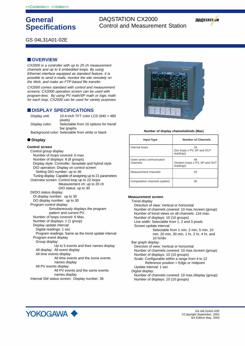
■ OVERVIEWCX2000 is a controller with up to 20 ch measurementchannels and up to 6 embedded loops. By usingEthernet interface equipped as standard feature, it ispossible to send e-mails, monitor the site remotely onthe Web, and make an FTP-based file transfer.
CX2000 comes standard with control and measurementscreens; CX2000 operation screen can be used withprogram-less. By using PV math/SP math or logic mathfor each loop, CX2000 can be used for variety purposes.
■ DISPLAY SPECIFICATIONSDisplay unit: 10.4-inch TFT color LCD (640 × 480
pixels)Display color: Selectable from 16 options for trend/
bar graphsBackground color: Selectable from white or black
● Display
Control screenControl group display
Number of loops covered: 6 max.Number of displays: 8 (8 groups)Display style: Controller, faceplate and hybrid styleDIO operation: Display on control screen
Setting DIO number: up to 36Tuning display: Capable of assigning up to 21 parameters
Overview screen: Control loop up to 22 loopsMeasurement ch: up to 20 chDIO status: up to 30
DI/DO status display:DI display number: up to 30DO display number: up to 30
Program control display:Simultaneously displays the programpattern and current PV.
Number of loops covered: 6 Max.Number of displays: 1 (1 group)Display update interval:
Digital readings: 1 secProgram readings: Same as the trend update interval
Program event displayGroup display:
Up to 5 events and their names displayAll display: All event displayAll time events display:
All time events and the some eventsnames display
All PV events display:All PV events and the some eventsnames display
Internal SW status screen: Display number: 36
GS 04L31A01-02E
GS 04L31A01-02E©Copyright September, 2001
3rd Edition May, 2003
Number of display channels/kinds (Max)
Input Type
Internal loops
Green series communication channels
Measurement channels
Computation channels (option)
18(Six loops x PV, SP and OUT readings)
48(Sixteen loops x PV, SP and OUT readings)
20
30
Number of Channels
Measurement screenTrend display
Direction of view: Vertical or horizontalNumber of channels covered: 10 max./screen (group)Number of trend views on all channels: 116 max.Number of displays: 10 (10 groups)Line width: Selectable from 1, 2 and 3 pixelsScreen update interval:
Selectable from 1 min, 2 min, 5 min, 10min, 20 min, 30 min, 1 hr, 2 hr, 4 hr, and10 hr/div
Bar graph display:Direction of view: Vertical or horizontalNumber of channels covered: 10 max./screen (group)Number of displays: 10 (10 groups)Scale: Configurable within a range from 4 to 12
Reference position = Edge or midpointUpdate interval: 1 sec
Digital display:Number of channels covered: 10 max./display (group)Number of displays: 10 (10 groups)
DAQSTATION CX2000Control and Measurement Station
2
All Rights Reserved. Copyright © 2001, Yokogawa Electric Corporation
<<Contents>> <<Index>>
GS 04L31A01-02E 3rd Edition May.20,2003-00
Update interval: 1 secOverview display:
50 channels max. (including computationchannels) for measurement
Measured values and alarms for all channels.Information display:
Jumps to the trend view of a data itemselected by the cursor.
Alarm summary display: Display the list of alarms.Event summary display:
Display the list of program events.Control operation summary screen:
Display the list of control operationstatuses.
Message summary display:Display the list of messages and time.
Memory summary display:Display the list of internal memory.
Tag display: Tag names for measurement channels (upto 16 alphanumeric characters)Tag names for control loops and DIO(up to 8 alphanumeric characters)Tag comments for control loops and DIO(up to 8 alphanumeric characters)
Other on-display elements:Memory status, scale values (0%, 100% -can be turned on/off), scales (10 scalesmax.), grid (selectable from a range of 4 to12 divisions) with hour:min indications, dateand time (year/month/day andhour:minute:second indications), trip line(selectable from 1-, 2- and 3-pixel thicknessoptions), messages (of up to 16 charactersand 8 types), and alarm marks
Data reference function:Display the retrieved data.
Display format: Bisectional or full-screen viewTime axis: Can be upscaled, downscaled, and
scrolled.Automatic screen switching
Switching interval5 sec, 10 sec, 20 sec, 30 sec, or 1 min
LCD back light saver functionTimer setpoint: 1, 2, 5, 10, 20 or 60 min
■ CONTROL FUNCTIONSControl mode
Single-loop control, cascade control, and loop controlwith PV switching.
Note) The control mode is fixed to single-loop control forloop 5 and 6.
Control computation functionsContinuous PID control, Relay on/off control, timeproportional PID control.PID parameter: 8 sets/loop for each control modePoints of zone PID switching: 6 max.“Super” function (overshoot prevention)Tracking functions: SP tracking PV trackingAnti-reset windup function
(over-integration prevention function)
Control interval: 250, 500 or 1000 ms
Operation mode switching• Switching among remote, local, and program modes• Switching among manual, auto, and cascade modes• Run/stop mode switching
Stop mode: Outputs the preset output value.• Switching between Execute/Stop options of auto-tuning
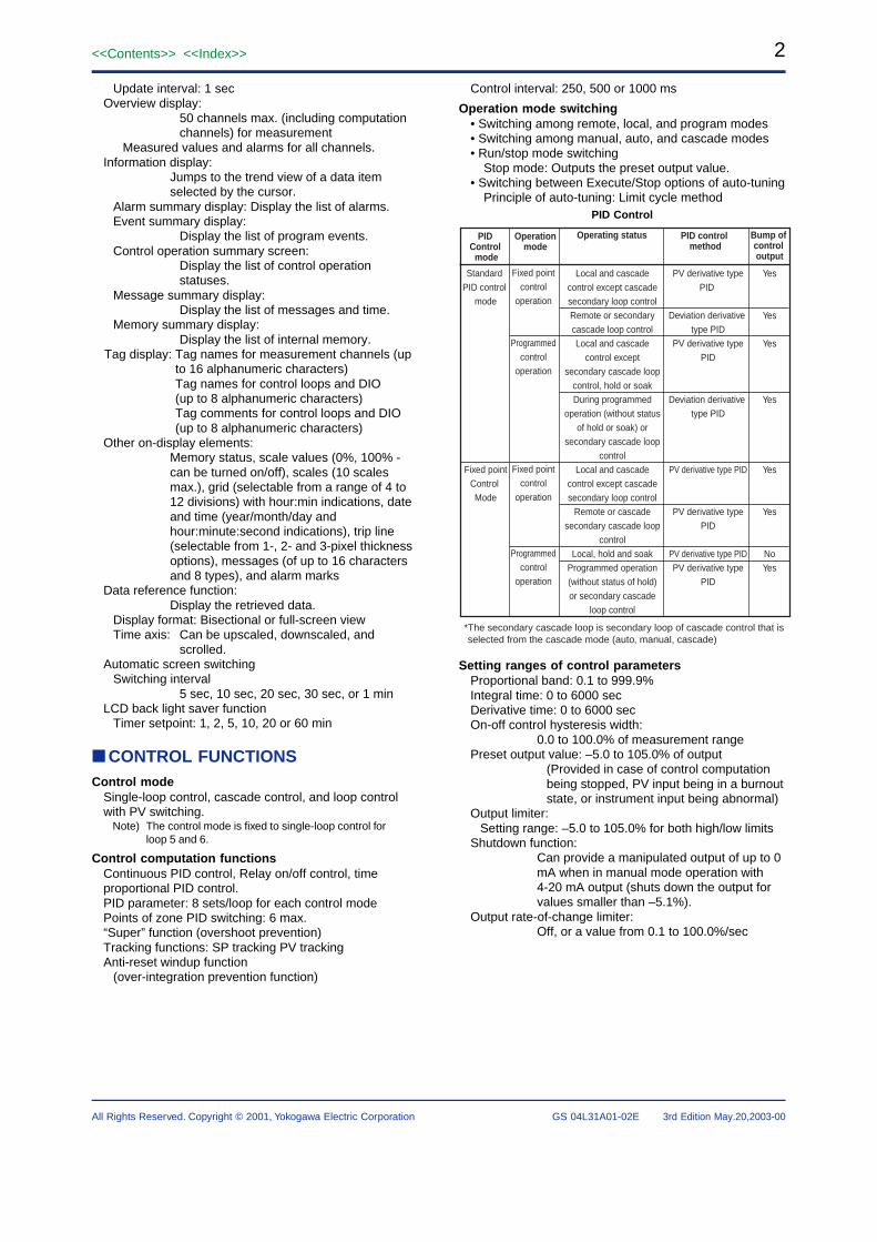
Principle of auto-tuning: Limit cycle methodPID Control
PID Control
mode
Bump of control output
Operating status
Standard PID control
mode
Fixed pointControl Mode
Operationmode
Fixed pointcontrol
operation
Programmedcontrol
operation
Fixed pointcontrol
operation
Programmedcontrol
operation
Yes
Yes
Yes
Yes
Yes
Yes
NoYes
PID control method
PV derivative type PID
Deviation derivative type PID
PV derivative type PID
Deviation derivative type PID
PV derivative type PID
PV derivative type PID
PV derivative type PIDPV derivative type
PID
Local and cascade control except cascade secondary loop controlRemote or secondary cascade loop controlLocal and cascade
control except secondary cascade loop
control, hold or soakDuring programmed
operation (without status of hold or soak) or
secondary cascade loop control
Local and cascade control except cascade secondary loop control
Remote or cascade secondary cascade loop
controlLocal, hold and soak
Programmed operation (without status of hold) or secondary cascade
loop control
*The secondary cascade loop is secondary loop of cascade control that is selected from the cascade mode (auto, manual, cascade)
Setting ranges of control parametersProportional band: 0.1 to 999.9%Integral time: 0 to 6000 secDerivative time: 0 to 6000 secOn-off control hysteresis width:
0.0 to 100.0% of measurement rangePreset output value: –5.0 to 105.0% of output
(Provided in case of control computationbeing stopped, PV input being in a burnoutstate, or instrument input being abnormal)
Output limiter:Setting range: –5.0 to 105.0% for both high/low limits
Shutdown function:Can provide a manipulated output of up to 0mA when in manual mode operation with4-20 mA output (shuts down the output forvalues smaller than –5.1%).
Output rate-of-change limiter:Off, or a value from 0.1 to 100.0%/sec
3<<Contents>> <<Index>>
All Rights Reserved. Copyright © 2001, Yokogawa Electric Corporation GS 04L31A01-02E 3rd Edition May.20,2003-00
● PV math/SP math functionMath expression can be assigned to PV and SP of eachloopType of computation:
Four arithmetic operations, square root,absolute, common logarithm, exponential,power, relational operations (�, �, �, �, �),logic operations (AND, OR, NOT, XOR),Statistical operations (average, Max. Min.Max.-Min. ) conditional operations ([expression1 ? expression 2 ? expression 3 ])
Note: Conditional operators can be used with the otheroperands together
Available operands for arithmetic operations:Measurement data, measurement mathdata, embedded/external control data,communication input data, constant W01-W36, control input data, control output DIO,expansion module DIO, measurementremote input, internal switch
Operation limitation: Within 120 charactersAvailable operands in an expression: less than 35
In error case: Over/Under selectionOver: Upper limit of PV/SP valueUnder: Lower limit of PV/SP value
● Logic MathAvailable number of operations: Up to 30Operation type: Relational operations (�, �, �, �, �),
logic operations (AND, OR, NOT, XOR),conditional operations( [expression 1 ?expression 2 ? expression 3 ])
Note: Conditional operators can be used with the otheroperands together
Available operands in an expression:Same as PV math/SP math operands
● Internal SWNumber of available internal SW: 36Non-hold type only
● Analog retransmissionOutput type: Current output (4-20mA, 0-20mA, 20-4mA,
20-0mA), time proportional voltage pulseoutput, time proportional relay output
Display/record: Data is recorded/displayed as out valueNote: The loop of analog retransmission mode can not
calculate PID computation.Available math operation: Same as PV math/SP mathAvailable operands: Same as PV math/SP math
■ ALARM FUNCTIONS
● Control AlarmTypes of control alarm:
PV high limit, PV low limit, high limit ofdeviation,low limit of deviation deviation highand low limits, deviation within high and lowlimits, SP high limit, SP low limit, OUT highlimit, and OUT low limit
Other alarm type: Fault diagnosis, fail outputStand-by action: Turns off PV/SP alarm from starting
control until steady conditionAlarm output: 6 points/ 2 loops (transistor output 4
points, relay output 2 points)Alarm setting: 4 types/ loopHysteresis: Can set each alarm settingDisplay: The status is shown in the digital display in
case of alarm. A common alarm indication isalso displayed.The alarming behavior: non-hold or hold-type selectable.
● Measurement AlarmNumber of alarm levels :
Up to four levels for each channelAlarm types: High and low limits, differential high and
low limits, high and low rate-of-change limitsand delay high and low
Alarm delay time :1 to 3600 sInterval time of rate-of-change alarms :
The measurement interval times 1 to 15Display : The alarm status (type) is displayed in the
digital value display area upon occurrence ofan alarm. A common alarm indication is alsodisplayed.The alarming behavior: non-hold or hold-type selectable.
Hysteresis :On (0.5% of display span)/off selectable(common to all channels and alarm levels)
Outputs : Number of points : 6 points (optional)Relay action: Energized/deenergized and hold/non-hold
selectable.Memory : The times of alarm occurrences/
recoveries,alarm types, etc. are stored in thememory. (Up to 120 latest alarm events arestored.)
Alarm display/record cancel function:In alarm occurrence, alarm display/recordcan be selected
■ INPUT SECTION
● Specifications Common to Control andMeasurement Inputs
Thermocouple burnout:Switchable between ON/OFF options ofdetection on a channel basis.Switchable between burnout upscale/downscale options
Burnout: Normal: less than 2k�Burnout: more than 10M�
Integral time of A/D converter:Select from the options of 20 ms (50 Hz),16.7 ms (60 Hz) , 100 ms (50/60 Hz) andAUTO (automatic switching between 20 msand 16.7 ms depending on the power supplyfrequency).
4
All Rights Reserved. Copyright © 2001, Yokogawa Electric Corporation
<<Contents>> <<Index>>
GS 04L31A01-02E 3rd Edition May.20,2003-00
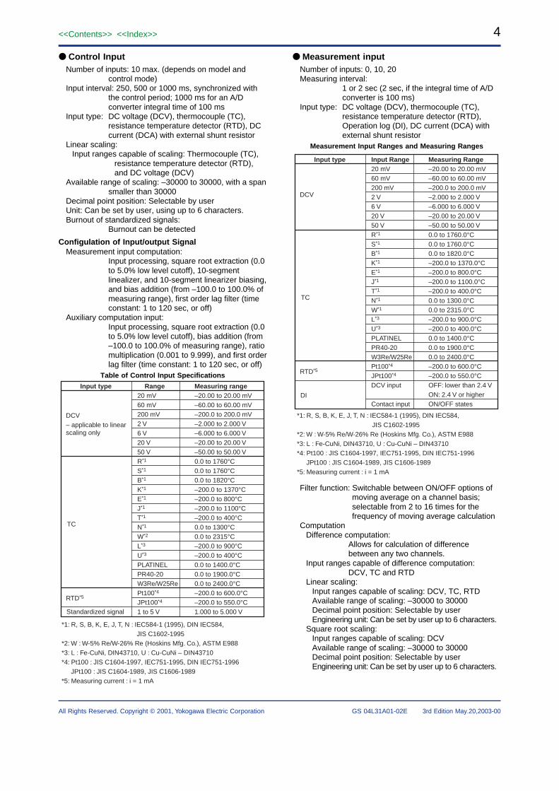
● Control InputNumber of inputs: 10 max. (depends on model and
control mode)Input interval: 250, 500 or 1000 ms, synchronized with
the control period; 1000 ms for an A/Dconverter integral time of 100 ms
Input type: DC voltage (DCV), thermocouple (TC),resistance temperature detector (RTD), DCcurrent (DCA) with external shunt resistor
Linear scaling:Input ranges capable of scaling: Thermocouple (TC),
resistance temperature detector (RTD),and DC voltage (DCV)
Available range of scaling: –30000 to 30000, with a spansmaller than 30000
Decimal point position: Selectable by userUnit: Can be set by user, using up to 6 characters.Burnout of standardized signals:
Burnout can be detected
Configulation of Input/output SignalMeasurement input computation:
Input processing, square root extraction (0.0to 5.0% low level cutoff), 10-segmentlinealizer, and 10-segment linearizer biasing,and bias addition (from –100.0 to 100.0% ofmeasuring range), first order lag filter (timeconstant: 1 to 120 sec, or off)
Auxiliary computation input:Input processing, square root extraction (0.0to 5.0% low level cutoff), bias addition (from–100.0 to 100.0% of measuring range), ratiomultiplication (0.001 to 9.999), and first orderlag filter (time constant: 1 to 120 sec, or off)
Table of Control Input Specifications
Input type Range20 mV60 mV200 mV2 V6 V20 V50 VR*1
S*1
B*1
K*1
E*1
J*1
T*1
N*1
W*2
L*3
U*3
PLATINELPR40-20W3Re/W25RePt100*4
JPt100*4
1 to 5 V
DCV– applicable to linear scaling only
TC
RTD*5
Standardized signal
*1: R, S, B, K, E, J, T, N : IEC584-1 (1995), DIN IEC584, JIS C1602-1995
*2: W : W-5% Re/W-26% Re (Hoskins Mfg. Co.), ASTM E988*3: L : Fe-CuNi, DIN43710, U : Cu-CuNi – DIN43710*4: Pt100 : JIS C1604-1997, IEC751-1995, DIN IEC751-1996
JPt100 : JIS C1604-1989, JIS C1606-1989*5: Measuring current : i = 1 mA
Measuring range–20.00 to 20.00 mV–60.00 to 60.00 mV–200.0 to 200.0 mV–2.000 to 2.000 V–6.000 to 6.000 V–20.00 to 20.00 V–50.00 to 50.00 V0.0 to 1760°C0.0 to 1760°C0.0 to 1820°C–200.0 to 1370°C–200.0 to 800°C–200.0 to 1100°C–200.0 to 400°C0.0 to 1300°C0.0 to 2315°C–200.0 to 900°C–200.0 to 400°C0.0 to 1400.0°C0.0 to 1900.0°C0.0 to 2400.0°C–200.0 to 600.0°C–200.0 to 550.0°C1.000 to 5.000 V
● Measurement inputNumber of inputs: 0, 10, 20Measuring interval:
1 or 2 sec (2 sec, if the integral time of A/Dconverter is 100 ms)
Input type: DC voltage (DCV), thermocouple (TC),resistance temperature detector (RTD),Operation log (DI), DC current (DCA) withexternal shunt resistor
Measurement Input Ranges and Measuring Ranges
Input type Input Range20 mV60 mV200 mV2 V6 V20 V50 VR*1
S*1
B*1
K*1
E*1
J*1
T*1
N*1
W*1
L*3
U*3
PLATINELPR40-20W3Re/W25RePt100*4
JPt100*4
DCV input
Contact input
DCV
TC
RTD*5
DI
Measuring Range–20.00 to 20.00 mV–60.00 to 60.00 mV–200.0 to 200.0 mV–2.000 to 2.000 V–6.000 to 6.000 V–20.00 to 20.00 V–50.00 to 50.00 V0.0 to 1760.0°C0.0 to 1760.0°C0.0 to 1820.0°C–200.0 to 1370.0°C–200.0 to 800.0°C–200.0 to 1100.0°C–200.0 to 400.0°C0.0 to 1300.0°C0.0 to 2315.0°C–200.0 to 900.0°C–200.0 to 400.0°C0.0 to 1400.0°C0.0 to 1900.0°C0.0 to 2400.0°C–200.0 to 600.0°C–200.0 to 550.0°COFF: lower than 2.4 VON: 2.4 V or higherON/OFF states
*1: R, S, B, K, E, J, T, N : IEC584-1 (1995), DIN IEC584, JIS C1602-1995
*2: W : W-5% Re/W-26% Re (Hoskins Mfg. Co.), ASTM E988*3: L : Fe-CuNi, DIN43710, U : Cu-CuNi – DIN43710*4: Pt100 : JIS C1604-1997, IEC751-1995, DIN IEC751-1996
JPt100 : JIS C1604-1989, JIS C1606-1989*5: Measuring current : i = 1 mA
Filter function: Switchable between ON/OFF options ofmoving average on a channel basis;selectable from 2 to 16 times for thefrequency of moving average calculation
ComputationDifference computation:
Allows for calculation of differencebetween any two channels.
Input ranges capable of difference computation:DCV, TC and RTD
Linear scaling:Input ranges capable of scaling: DCV, TC, RTDAvailable range of scaling: –30000 to 30000Decimal point position: Selectable by userEngineering unit: Can be set by user up to 6 characters.
Square root scaling:Input ranges capable of scaling: DCVAvailable range of scaling: –30000 to 30000Decimal point position: Selectable by userEngineering unit: Can be set by user up to 6 characters.
5<<Contents>> <<Index>>
All Rights Reserved. Copyright © 2001, Yokogawa Electric Corporation GS 04L31A01-02E 3rd Edition May.20,2003-00
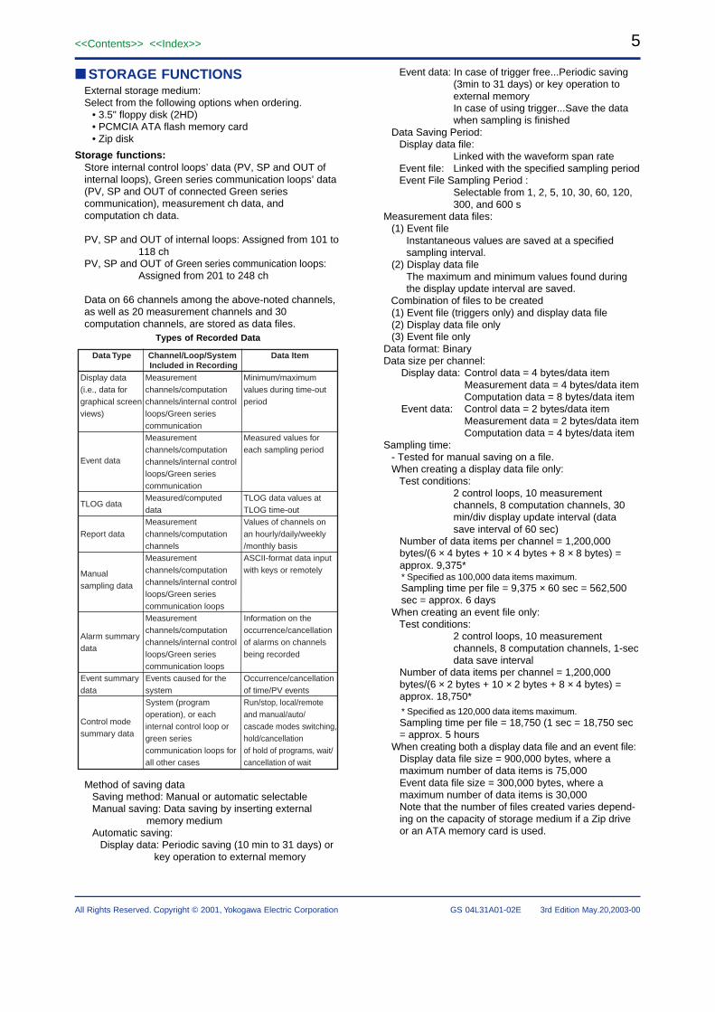
■ STORAGE FUNCTIONSExternal storage medium:Select from the following options when ordering.
• 3.5" floppy disk (2HD)• PCMCIA ATA flash memory card• Zip disk
Storage functions:Store internal control loops’ data (PV, SP and OUT ofinternal loops), Green series communication loops’ data(PV, SP and OUT of connected Green seriescommunication), measurement ch data, andcomputation ch data.
PV, SP and OUT of internal loops: Assigned from 101 to118 ch
PV, SP and OUT of Green series communication loops:Assigned from 201 to 248 ch
Data on 66 channels among the above-noted channels,as well as 20 measurement channels and 30computation channels, are stored as data files.
Types of Recorded Data
Data Type Data ItemChannel/Loop/System Included in Recording
Measurement channels/computation channels/internal control loops/Green series communicationMeasurement channels/computation channels/internal control loops/Green series communicationMeasured/computed dataMeasurement channels/computation channelsMeasurement channels/computation channels/internal control loops/Green series communication loopsMeasurement channels/computation channels/internal control loops/Green series communication loopsEvents caused for the systemSystem (program operation), or each internal control loop or green series communication loops for all other cases
Minimum/maximum values during time-out period
Measured values for each sampling period
TLOG data values at TLOG time-outValues of channels on an hourly/daily/weekly/monthly basisASCII-format data input with keys or remotely
Information on the occurrence/cancellation of alarms on channels being recorded
Occurrence/cancellation of time/PV eventsRun/stop, local/remote and manual/auto/cascade modes switching, hold/cancellationof hold of programs, wait/cancellation of wait
Display data (i.e., data for graphical screen views)
Event data
TLOG data
Report data
Manual sampling data
Alarm summary data
Event summary data
Control mode summary data
Method of saving dataSaving method: Manual or automatic selectableManual saving: Data saving by inserting external
memory mediumAutomatic saving:
Display data: Periodic saving (10 min to 31 days) orkey operation to external memory
Event data: In case of trigger free...Periodic saving(3min to 31 days) or key operation toexternal memoryIn case of using trigger...Save the datawhen sampling is finished
Data Saving Period:Display data file:
Linked with the waveform span rateEvent file: Linked with the specified sampling periodEvent File Sampling Period :
Selectable from 1, 2, 5, 10, 30, 60, 120,300, and 600 s
Measurement data files:(1) Event file
Instantaneous values are saved at a specifiedsampling interval.
(2) Display data fileThe maximum and minimum values found duringthe display update interval are saved.
Combination of files to be created(1) Event file (triggers only) and display data file(2) Display data file only(3) Event file only
Data format: BinaryData size per channel:
Display data: Control data = 4 bytes/data itemMeasurement data = 4 bytes/data itemComputation data = 8 bytes/data item
Event data: Control data = 2 bytes/data itemMeasurement data = 2 bytes/data itemComputation data = 4 bytes/data item
Sampling time:- Tested for manual saving on a file.When creating a display data file only:
Test conditions:2 control loops, 10 measurementchannels, 8 computation channels, 30min/div display update interval (datasave interval of 60 sec)
Number of data items per channel = 1,200,000bytes/(6 × 4 bytes + 10 × 4 bytes + 8 × 8 bytes) =approx. 9,375** Specified as 100,000 data items maximum.Sampling time per file = 9,375 × 60 sec = 562,500sec = approx. 6 days
When creating an event file only:Test conditions:
2 control loops, 10 measurementchannels, 8 computation channels, 1-secdata save interval
Number of data items per channel = 1,200,000bytes/(6 × 2 bytes + 10 × 2 bytes + 8 × 4 bytes) =approx. 18,750** Specified as 120,000 data items maximum.Sampling time per file = 18,750 (1 sec = 18,750 sec= approx. 5 hours
When creating both a display data file and an event file:Display data file size = 900,000 bytes, where amaximum number of data items is 75,000Event data file size = 300,000 bytes, where amaximum number of data items is 30,000Note that the number of files created varies depend-ing on the capacity of storage medium if a Zip driveor an ATA memory card is used.
6
All Rights Reserved. Copyright © 2001, Yokogawa Electric Corporation
<<Contents>> <<Index>>
GS 04L31A01-02E 3rd Edition May.20,2003-00
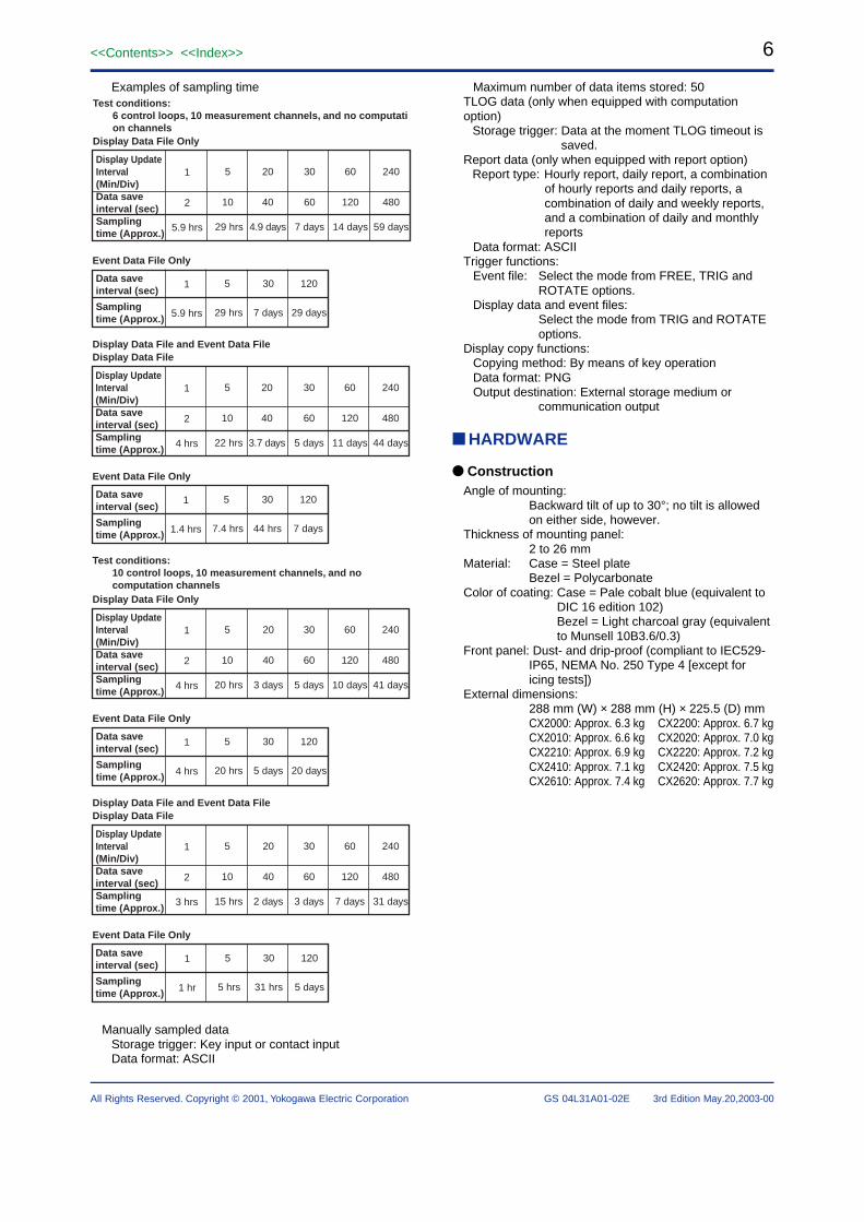
Examples of sampling time
Display Update Interval (Min/Div)Data save interval (sec)Sampling time (Approx.)
1
2
5.9 hrs
5
10
29 hrs
30
60
7 days
20
40
4.9 days
60
120
14 days
240
480
59 days
Test conditions: 6 control loops, 10 measurement channels, and no computati on channelsDisplay Data File Only
Data save interval (sec)
Sampling time (Approx.)
1
5.9 hrs
5
29 hrs
30
7 days
120
29 days
Event Data File Only
Display Update Interval (Min/Div)Data save interval (sec)Sampling time (Approx.)
1
2
4 hrs
5
10
22 hrs
30
60
5 days
20
40
3.7 days
60
120
11 days
240
480
44 days
Display Data File and Event Data FileDisplay Data File
Data save interval (sec)
Sampling time (Approx.)
1
1.4 hrs
5
7.4 hrs
30
44 hrs
120
7 days
Event Data File Only
Display Update Interval (Min/Div)Data save interval (sec)Sampling time (Approx.)
1
2
4 hrs
5
10
20 hrs
30
60
5 days
20
40
3 days
60
120
10 days
240
480
41 days
Test conditions: 10 control loops, 10 measurement channels, and no computation channelsDisplay Data File Only
Data save interval (sec)
Sampling time (Approx.)
1
4 hrs
5
20 hrs
30
5 days
120
20 days
Event Data File Only
Display Update Interval (Min/Div)Data save interval (sec)Sampling time (Approx.)
1
2
3 hrs
5
10
15 hrs
30
60
3 days
20
40
2 days
60
120
7 days
240
480
31 days
Display Data File and Event Data FileDisplay Data File
Data save interval (sec)
Sampling time (Approx.)
1
1 hr
5
5 hrs
30
31 hrs
120
5 days
Event Data File Only
Manually sampled dataStorage trigger: Key input or contact inputData format: ASCII
Maximum number of data items stored: 50TLOG data (only when equipped with computationoption)
Storage trigger: Data at the moment TLOG timeout issaved.
Report data (only when equipped with report option)Report type: Hourly report, daily report, a combination
of hourly reports and daily reports, acombination of daily and weekly reports,and a combination of daily and monthlyreports
Data format: ASCIITrigger functions:
Event file: Select the mode from FREE, TRIG andROTATE options.
Display data and event files:Select the mode from TRIG and ROTATEoptions.
Display copy functions:Copying method: By means of key operationData format: PNGOutput destination: External storage medium or
communication output
■ HARDWARE
● ConstructionAngle of mounting:
Backward tilt of up to 30°; no tilt is allowedon either side, however.
Thickness of mounting panel:2 to 26 mm
Material: Case = Steel plateBezel = Polycarbonate
Color of coating: Case = Pale cobalt blue (equivalent toDIC 16 edition 102)Bezel = Light charcoal gray (equivalentto Munsell 10B3.6/0.3)
Front panel: Dust- and drip-proof (compliant to IEC529-IP65, NEMA No. 250 Type 4 [except foricing tests])
External dimensions:288 mm (W) × 288 mm (H) × 225.5 (D) mmCX2000: Approx. 6.3 kg CX2200: Approx. 6.7 kgCX2010: Approx. 6.6 kg CX2020: Approx. 7.0 kgCX2210: Approx. 6.9 kg CX2220: Approx. 7.2 kgCX2410: Approx. 7.1 kg CX2420: Approx. 7.5 kgCX2610: Approx. 7.4 kg CX2620: Approx. 7.7 kg
7<<Contents>> <<Index>>
All Rights Reserved. Copyright © 2001, Yokogawa Electric Corporation GS 04L31A01-02E 3rd Edition May.20,2003-00
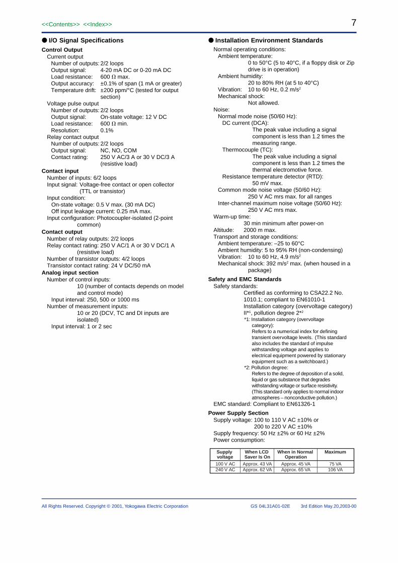
● I/O Signal SpecificationsControl Output
Current outputNumber of outputs: 2/2 loopsOutput signal: 4-20 mA DC or 0-20 mA DCLoad resistance: 600 � max.Output accuracy: ±0.1% of span (1 mA or greater)Temperature drift: ±200 ppm/°C (tested for output
section)Voltage pulse output
Number of outputs: 2/2 loopsOutput signal: On-state voltage: 12 V DCLoad resistance: 600 � min.Resolution: 0.1%
Relay contact outputNumber of outputs: 2/2 loopsOutput signal: NC, NO, COMContact rating: 250 V AC/3 A or 30 V DC/3 A
(resistive load)Contact input
Number of inputs: 6/2 loopsInput signal: Voltage-free contact or open collector
(TTL or transistor)Input condition:
On-state voltage: 0.5 V max. (30 mA DC)Off input leakage current: 0.25 mA max.
Input configuration: Photocoupler-isolated (2-pointcommon)
Contact outputNumber of relay outputs: 2/2 loopsRelay contact rating: 250 V AC/1 A or 30 V DC/1 A
(resistive load)Number of transistor outputs: 4/2 loopsTransistor contact rating: 24 V DC/50 mA
Analog input sectionNumber of control inputs:
10 (number of contacts depends on modeland control mode)
Input interval: 250, 500 or 1000 msNumber of measurement inputs:
10 or 20 (DCV, TC and DI inputs areisolated)
Input interval: 1 or 2 sec
● Installation Environment StandardsNormal operating conditions:
Ambient temperature:0 to 50°C (5 to 40°C, if a floppy disk or Zipdrive is in operation)
Ambient humidity:20 to 80% RH (at 5 to 40°C)
Vibration: 10 to 60 Hz, 0.2 m/s2
Mechanical shock:Not allowed.
Noise:Normal mode noise (50/60 Hz):
DC current (DCA):The peak value including a signalcomponent is less than 1.2 times themeasuring range.
Thermocouple (TC):The peak value including a signalcomponent is less than 1.2 times thethermal electromotive force.
Resistance temperature detector (RTD):50 mV max.
Common mode noise voltage (50/60 Hz):250 V AC mrs max. for all ranges
Inter-channel maximum noise voltage (50/60 Hz):250 V AC mrs max.
Warm-up time:30 min minimum after power-on
Altitude: 2000 m max.Transport and storage conditions:
Ambient temperature: –25 to 60°CAmbient humidity: 5 to 95% RH (non-condensing)Vibration: 10 to 60 Hz, 4.9 m/s2
Mechanical shock: 392 m/s2 max. (when housed in apackage)
Safety and EMC StandardsSafety standards:
Certified as conforming to CSA22.2 No.1010.1; compliant to EN61010-1Installation category (overvoltage category)II*1, pollution degree 2*2
*1: Installation category (overvoltagecategory):Refers to a numerical index for definingtransient overvoltage levels. (This standardalso includes the standard of impulsewithstanding voltage and applies toelectrical equipment powered by stationaryequipment such as a switchboard.)
*2: Pollution degree:Refers to the degree of deposition of a solid,liquid or gas substance that degradeswithstanding voltage or surface resistivity.(This standard only applies to normal indooratmospheres – nonconductive pollution.)
EMC standard: Compliant to EN61326-1
Power Supply SectionSupply voltage: 100 to 110 V AC ±10% or
200 to 220 V AC ±10%Supply frequency: 50 Hz ±2% or 60 Hz ±2%Power consumption:
Supply voltage
When LCD Saver Is On
When in Normal Operation
Maximum
100 V AC240 V AC
Approx. 43 VAApprox. 62 VA
Approx. 45 VAApprox. 65 VA
75 VA106 VA
8
All Rights Reserved. Copyright © 2001, Yokogawa Electric Corporation
<<Contents>> <<Index>>
GS 04L31A01-02E 3rd Edition May.20,2003-00
IsolationInsulation resistance:
20 M� min. between each terminal andground (at 500 V DC)
Withstanding voltage:Between power supply terminal and ground:
1500 V AC (50/60 Hz), 1 minBetween relay contact output terminal and ground:
1500 V AC (50/60 Hz), 1 minBetween measurement input terminal and ground:
1500 V AC (50/60 Hz), 1 minBetween measurement input terminals:
1000 V AC (50/60 Hz), 1 minBetween contact input and ground:
500 V DC, 1 minBetween current output terminal and ground:
500 V AC (50/60 Hz), 1 minBetween voltage pulse output terminal and ground:
500 V AC (50/60 Hz), 1 minBetween transistor contact output terminal and ground:
500 V DC, 1 minGrounding: Grounding resistance, less than 100 �Control input terminals:
Isolated from other input/output terminals,with inter-channel isolation.
Measurement inputs:Isolated from other input/output terminals,with inter-channel isolation (b terminal iscommon for optional RTD).
Voltage pulse control output terminals*:Not isolated from DC output terminals butisolated from other input/output terminals.
Current output terminals*:Not isolated from voltage pulse controloutput terminals but isolated from otherinput/output terminals.
Control output (relay) terminals*:Isolated from other input/output terminals.
Contact input terminals:Not isolated from other contact inputterminals but isolated from other input/output terminals.
Contact output (relay) terminals:Isolated from other input/output terminals.
Contact output (transistor) terminals:Not isolated between transistors butisolated from other input/output terminals.
Extension DIO module:Isolated from other input/output terminals.
/TPS module:Isolated from other input/output terminals,with inter-channel isolation.
Alarm output terminals:Isolated from other input/output terminals.
Alarm remote terminals:Not isolated from DI but isolated from otherinput/output terminals.
RS-232C: Not isolated from case.RS-422/485:
Isolated from other input/output terminals.Ethernet: Isolated from other input/output terminals.Power terminals:
Isolated from other input/output terminals.Grounding terminals:
At case potential.*: Control outputs have inter-loop isolation.
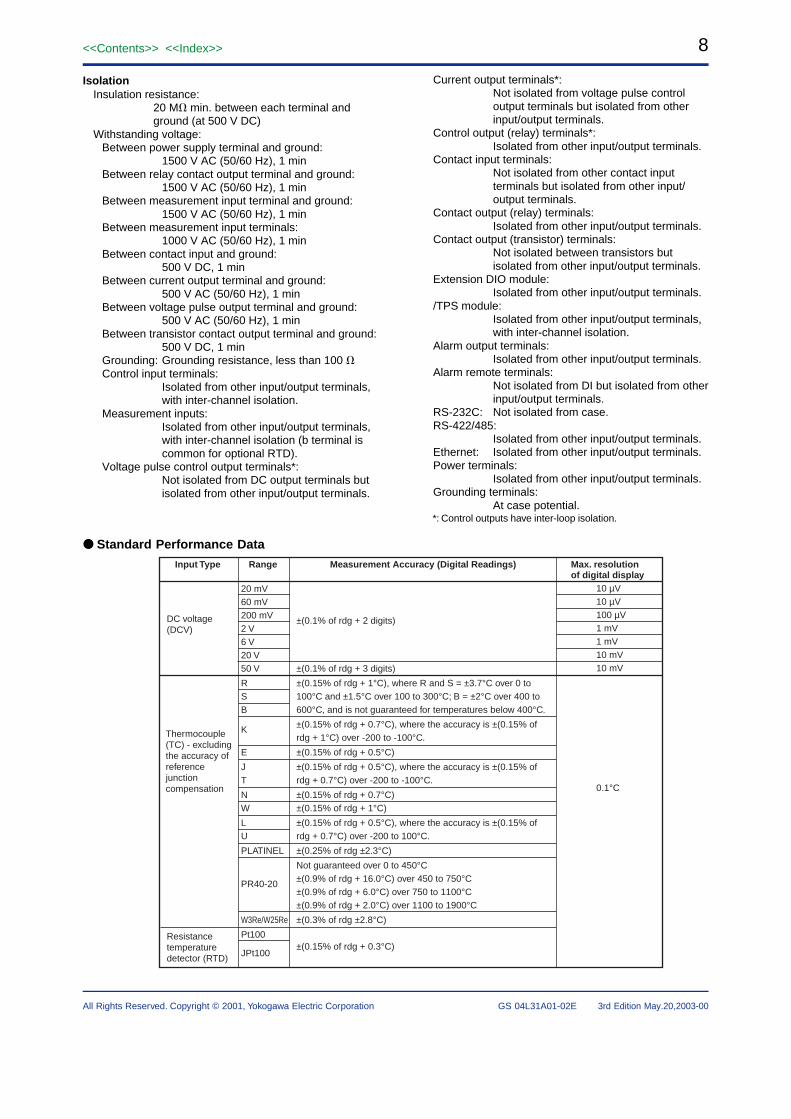
● Standard Performance Data
Input Type Range
20 mV60 mV200 mV2 V6 V20 V50 V
RSB
K
E
JT
NW
LU
PLATINEL
PR40-20
W3Re/W25Re
Pt100
JPt100
Measurement Accuracy (Digital Readings)
±(0.1% of rdg + 2 digits)
±(0.1% of rdg + 3 digits)
±(0.15% of rdg + 1°C), where R and S = ±3.7°C over 0 to 100°C and ±1.5°C over 100 to 300°C; B = ±2°C over 400 to 600°C, and is not guaranteed for temperatures below 400°C.
±(0.15% of rdg + 0.7°C), where the accuracy is ±(0.15% of rdg + 1°C) over -200 to -100°C.
±(0.15% of rdg + 0.5°C)
±(0.15% of rdg + 0.5°C), where the accuracy is ±(0.15% of rdg + 0.7°C) over -200 to -100°C.
±(0.15% of rdg + 0.7°C)±(0.15% of rdg + 1°C)
±(0.15% of rdg + 0.5°C), where the accuracy is ±(0.15% of rdg + 0.7°C) over -200 to 100°C.
±(0.25% of rdg ±2.3°C)
Not guaranteed over 0 to 450°C±(0.9% of rdg + 16.0°C) over 450 to 750°C±(0.9% of rdg + 6.0°C) over 750 to 1100°C±(0.9% of rdg + 2.0°C) over 1100 to 1900°C±(0.3% of rdg ±2.8°C)
±(0.15% of rdg + 0.3°C)
DC voltage (DCV)
Thermocouple (TC) - excluding the accuracy of reference junction compensation
Resistance temperature detector (RTD)
Max. resolution of digital display
10 µV10 µV100 µV1 mV1 mV10 mV10 mV
0.1°C
9<<Contents>> <<Index>>
All Rights Reserved. Copyright © 2001, Yokogawa Electric Corporation GS 04L31A01-02E 3rd Edition May.20,2003-00
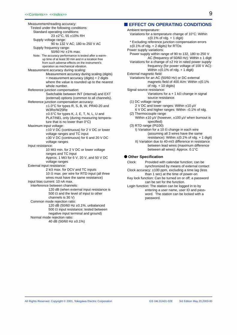
Measurement/reading accuracy:Tested under the following conditions:
Standard operating conditions:23 ±2°C, 55 ±10% RH
Supply voltage range:90 to 132 V AC; 180 to 250 V AC
Supply frequency range:50/60 Hz ±1% max.
Note: The accuracy performance is tested after a warm-up time of at least 30 min and in a location freefrom such adverse effects on the instrument’soperation as mechanical vibration.
Measurement accuracy during scaling:Measurement accuracy during scaling (digits)= measurement accuracy (digits) + 2 digitswhere the value is rounded up to the nearestwhole number.
Reference junction compensation:Switchable between INT (internal) and EXT(external) options (common to all channels).
Reference junction compensation accuracy:±1.0°C for types R, S, B, W, PR40-20 andW3Re/W25Re±0.5°C for types K, J, E, T, N, L, U andPLATINEL only (during measuring tempera-ture that is no lower than 0°C)
Maximum input voltage:±10 V DC (continuous) for 2 V DC or lowervoltage ranges and TC input±30 V DC (continuous) for 6 and 20 V DCvoltage ranges
Input resistance:10 M� min. for 2 V DC or lower voltageranges and TC inputApprox. 1 M� for 6 V, 20 V, and 50 V DCvoltage ranges
External input resistance:2 k� max. for DCV and TC inputs10 � max. per wire for RTD input (all threewires must have the same resistance)
Input bias current: 10 nA max.Interference between channels:
120 dB (when external input resistance is500 � and the level of input to otherchannels is 30 V)
Common mode rejection ratio:120 dB (50/60 Hz ±0.1%, unbalanced500 � input resistance; tested betweennegative input terminal and ground)
Normal mode rejection ratio:40 dB (50/60 Hz ±0.1%)
■ EFFECT ON OPERATING CONDITIONSAmbient temperature:
Variations for a temperature change of 10°C: Within±(0.1% of rdg. + 1 digit)
* Excluding reference junction compensation errors±(0.1% of rdg. + 2 digits) for RTDs
Power supply variations:Power supply within range of 90 to 132, 180 to 250 V
AC (frequency of 50/60 Hz): Within ± 1 digitVariations for a change of ±2 Hz in rated power supply
frequency (for power voltage of 100 V AC):Within ±(0.1% of rdg. + 1 digit)
External magnetic field:Variations for an AC (50/60 Hz) or DC external
magnetic field of 400 A/m: Within ±(0.1%of rdg. + 10 digits)
Signal source resistance:Variations for a + 1 k� change in signalsource resistance.
(1) DC voltage range 2 V DC and lower ranges: Within ±10 µV 6 V DC and higher ranges: Within –0.1% of rdg.(2) Thermocouple range Within ±10 µV (however, ±100 µV when burnout is
specified)(3) RTD range (Pt100) I) Variation for a 10 � change in each wire
(assuming all 3 wires have the sameresistance): Within ±(0.1% of rdg. + 1 digit)
II) Variation due to 40-m� difference in resistancebetween lead wires (maximum differencebetween all wires): Approx. 0.1°C
● Other SpecificationClock: Provided with calendar function; can be
synchronized by means of external contactClock accuracy: ±100 ppm, excluding a time lag (less
than 1 sec) at the time of power-onKey lock function: Can be turned on or off; a password
can be set for the function.Login function: The station can be logged in to by
entering a user name, user ID and pass-word. The station can be locked with apassword.
10
All Rights Reserved. Copyright © 2001, Yokogawa Electric Corporation
<<Contents>> <<Index>>
GS 04L31A01-02E 3rd Edition May.20,2003-00
■ COMMUNICATION FUNCTIONS
● Ethernet CommunicationMedium: Ethernet (10BASE-T)Basis protocol:
SMTP, HTTP1.0, FTP, TCP, UDP, IP, ARPand ICMP
E-mail function:Recipient address:
2 address groups (two or more addressescan be specified for each group using nomore than 150 characters)
Types of message:The following pieces of information can besent via e-mail; for each address group, aselection can be made as to whether ornot to send the information.
Alarm inform:Inform in occurring alarm/cancelingalarm
System inform:Inform in recovering power failure/inform the time of recovering, informthe rest of time before rewriting oninside memory (manual save mode),inform the rest of amount in reaching90% of media volume (auto savemode)
Scheduled time inform:Inform the moment value at a certaintime or interval
Report inform:Inform report data in report timeup (/M1is equipped)
Real time monitoring function:Real time monitoring DX data bycommunication (Yokogawa privateprotocol)
Web server function:Shows screen images, alarms, instanta-neous values and other information usingBrowser software (Internet Explorer 5.0).
FTP client function:Transfers files automatically.
FTP server function:Acquires or deletes files, or manipulatesdirectories from the host computer, andprovides information on the remaining sizeof memory.
FTP server function:Manipulates directories in an externalstorage medium, outputs or deletes filesfrom the medium, and provides informationon the remaining size of memory.
Real-time monitor function:real time monitoring DX data bycommunication (Yokogawa privateprotocol)
CX PC-UT gateway function:By using CX as gateway, external UT parameters canbe set from PC.
● Serial CommunicationThis type of communication is used for ladder communi-cation, digital indicating controller communication, andmodbus communication.Medium: EIA RS-232 (CX2xx0-x-1-x)
EIA RS-422A/485 (CX2xxx0-x-2-x)Protocol: Dedicated protocol or Modbus protocolSynchronization:
Start-stop synchronizationCommunication method (RS-422A/485):
Four-wire, half-duplex multi-drop connection(1:N, where N = 1 to 31)
Transfer rate: 1200, 2400, 4800, 9600, 19200, or 38400bps
Data length: 7 or 8 bitsNumber of stop bits: 1Parity: ODD, EVEN or NONEOverall communication distance (RS-422A/485): 1.2 kmCommunication mode:
ASCII for input/output of control and settingdataASCII or binary for output of measured data
Modbus communication:Operating mode: RTU MASTER or RTU SLAVERTU MASTER: Performs communication with
temperature controllerRTU SLAVE: Outputs measured/computed data, alarm
statuses, and so on.Ladder communication:
Data input/output by means of BCD code
● Green Series CommunicationThis function is for communicating with YokogawaM&C’s UT series. Supported controller models areUT3x0, UT3x1, UT4x0, UT5x0, UT750, and otherspecific models (Only Read and record support).
● Ladder CommunicationLadder communication is a communication protocolused to communicate with Programmable LogicControllers (PLCs) that are capable of laddercommunications.
11<<Contents>> <<Index>>
All Rights Reserved. Copyright © 2001, Yokogawa Electric Corporation GS 04L31A01-02E 3rd Edition May.20,2003-00
■ OPTIONS
● Program Setting Functions (/PG1, /PG2)Program setting functions
Number of program patterns: 4 (/PG1), 30 (/PG2)Number of segments per program pattern: 99 max.Number of program segments: 300 max.
(as the sum of segments for all programpatterns)
Number of program events: 800 max.Number of program repetitions: 999 max. or infiniteSegment time: 0 min: 1 sec to 99 hr:59 min:59 secStart/stop of program pattern:
A program pattern can be started(RUN),stopped(RESET), held(Hold) or advanced bymeans of contact input or instrument operation.
Switching among program patterns:A program pattern can be switched toanother by means of contact input orinstrument operation.
Advance function:Forcibly moves the program to the next segment
Wait function:Wait time: Off, or 0 min:1 sec to 99 hr:59 min:59 secWait zone: 0.0 to 100.0% of the span of
measurement input rangePID parameters switching
Segment PID selection:PID-parameter numbers being used canbe selected on a segment basis
Zone PID selection:PID parameter sets are switched dependingon the value of the applied PV input
Time event:The progress status of a program pattern is providedby means of contact output.(ON/OFF)Number of events set: 16 max. per segmentOutput: Provided after the lapse of a specified time
from the moment of segment switchover.Range of time lapse: 0 to 99 hr:59 min:59 sec
PV event:Alarm function for measured values/deviations within aprogram patternNumber of events set: 16 max. per segmentEvent type: PV high limit, PV low limit, high limit of
deviation, low limit of deviation, deviationwithin high and low limits, SP high limit, SPlow limit, Out high limit, Out low limit
Control mode switchingRESET/RUN switching for programoperation: Run/stop status of program operationHold/non-Hold options:
The progress of program operation can beplaced in a Hold state or non-Hold statewhile in the Run status of a program.
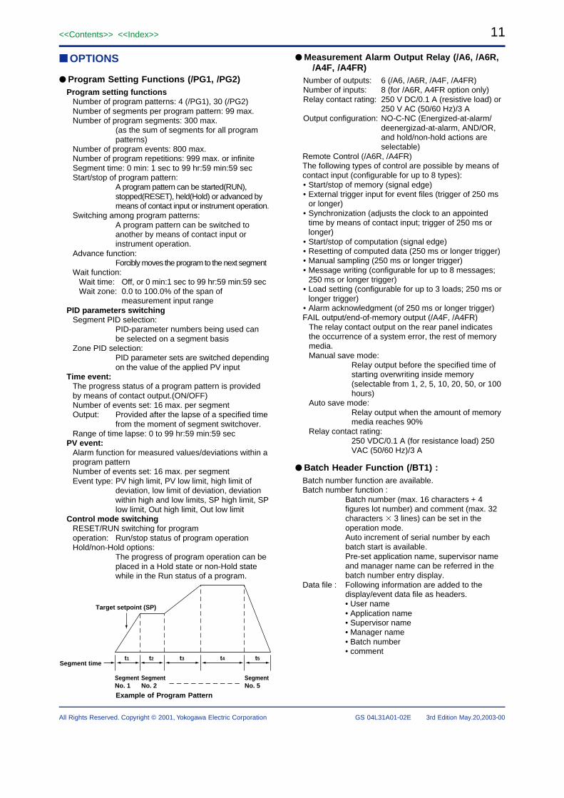
Segment time
Target setpoint (SP)
t1 t2 t3 t4 t5
Segment No. 1
Segment No. 2
Segment No. 5
Example of Program Pattern
● Measurement Alarm Output Relay (/A6, /A6R,/A4F, /A4FR)
Number of outputs: 6 (/A6, /A6R, /A4F, /A4FR)Number of inputs: 8 (for /A6R, A4FR option only)Relay contact rating: 250 V DC/0.1 A (resistive load) or
250 V AC (50/60 Hz)/3 AOutput configuration: NO-C-NC (Energized-at-alarm/
deenergizad-at-alarm, AND/OR,and hold/non-hold actions areselectable)
Remote Control (/A6R, /A4FR)The following types of control are possible by means ofcontact input (configurable for up to 8 types):• Start/stop of memory (signal edge)• External trigger input for event files (trigger of 250 ms
or longer)• Synchronization (adjusts the clock to an appointed
time by means of contact input; trigger of 250 ms orlonger)
• Start/stop of computation (signal edge)• Resetting of computed data (250 ms or longer trigger)• Manual sampling (250 ms or longer trigger)• Message writing (configurable for up to 8 messages;
250 ms or longer trigger)• Load setting (configurable for up to 3 loads; 250 ms or
longer trigger)• Alarm acknowledgment (of 250 ms or longer trigger)FAIL output/end-of-memory output (/A4F, /A4FR)
The relay contact output on the rear panel indicatesthe occurrence of a system error, the rest of memorymedia.Manual save mode:
Relay output before the specified time ofstarting overwriting inside memory(selectable from 1, 2, 5, 10, 20, 50, or 100hours)
Auto save mode:Relay output when the amount of memorymedia reaches 90%
Relay contact rating:250 VDC/0.1 A (for resistance load) 250VAC (50/60 Hz)/3 A
● Batch Header Function (/BT1) :Batch number function are available.Batch number function :
Batch number (max. 16 characters + 4figures lot number) and comment (max. 32characters � 3 lines) can be set in theoperation mode.Auto increment of serial number by eachbatch start is available.Pre-set application name, supervisor nameand manager name can be referred in thebatch number entry display.
Data file : Following information are added to thedisplay/event data file as headers.• User name• Application name• Supervisor name• Manager name• Batch number• comment
12
All Rights Reserved. Copyright © 2001, Yokogawa Electric Corporation
<<Contents>> <<Index>>
GS 04L31A01-02E 3rd Edition May.20,2003-00
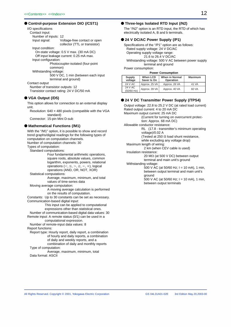
● Control-purpose Extension DIO (/CST1)I/O specifications
Contact input:Number of inputs: 12Input signal: Voltage-free contact or open
collector (TTL or transistor)Input condition:
On-state voltage: 0.5 V max. (30 mA DC)Off input leakage current: 0.25 mA max.
Input configuration:Photocoupler-isolated (four-pointcommon)
Withstanding voltage:500 V DC, 1 min (between each inputterminal and ground)
Contact outputNumber of transistor outputs: 12Transistor contact rating: 24 V DC/50 mA
● VGA Output (/D5)This option allows for connection to an external displayunit.
Resolution: 640 × 480 pixels (compatible with the VGAstandard)
Connector: 15-pin Mini D-sub
● Mathematical Functions (/M1)With the “/M1” option, it is possible to show and recordtrend graphs/digital readings for the following types ofcomputation on computation channels.Number of computation channels: 30Types of computation:
Standard computations:Four fundamental arithmetic operations,square roots, absolute values, commonlogarithm, exponents, powers, relationaloperations (�, �, �, �, �, �), logicaloperations (AND, OR, NOT, XOR)
Statistical computations:Average, maximum, minimum, and totalvalues of time-series data
Moving average computation:A moving average calculation is performedon the results of computation.
Constants: Up to 30 constants can be set as necessary.Communication-based digital input:
This input can be applied to computationalexpressions other than statistical ones.
Number of communication-based digital data values: 30Remote input: A remote status (0/1) can be used in a
computational expression.Number of remote-input data values: 8
Report functions:Report type: Hourly report, daily report, a combination
of hourly and daily reports, a combinationof daily and weekly reports, and acombination of daily and monthly reports
Type of computation:Average, maximum, minimum, total
Data format: ASCII
● Three-legs Isolated RTD Input (/N2)The “/N2” option is an RTD input, the RTD of which haselectrically isolated A, B and b terminals.
● 24 V DC/AC Power Supply (/P1)Specifications of the “/P1” option are as follows:
Rated supply voltage: 24 V DC/ACOperating supply voltage range:
21.6 to 26.4 V DC/ACWithstanding voltage: 500 V AC between power supply
terminal and groundPower consumption:
Power Consumption
Supply voltage
When LCD Saver Is On
When in Normal Operation
Maximum
24 V AC24 V AC(50/60 Hz)
Approx. 25 VA
Approx. 39 VA
Approx. 26 VA
Approx. 40 VA
41 VA
60 VA
● 24 V DC Transmitter Power Supply (/TPS4)Output voltage: 22.8 to 25.2 V DC (at rated load current)Rated output current: 4 to 20 mA DCMaximum output current: 25 mA DC
(Current for turning on overcurrent protec-tion: Approx. 68 mA DC)
Allowable conductor resistance:RL (17.8 - transmitter’s minimum operatingvoltage)/0.02 A(Tested at 250 � load shunt resistance,while excluding any voltage drop)
Maximum length of wiring:2 km (when CEV cable is used)
Insulation resistance:20 M� (at 500 V DC) between outputterminal and main unit’s ground
Withstanding voltage:500 V AC (at 50/60 Hz; I = 10 mA), 1 min,between output terminal and main unit’sground500 V AC (at 50/60 Hz; I = 10 mA), 1 min,between output terminals
13<<Contents>> <<Index>>
All Rights Reserved. Copyright © 2001, Yokogawa Electric Corporation GS 04L31A01-02E 3rd Edition May.20,2003-00
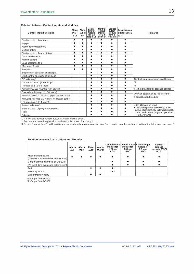
Contact input is common to all loops*2*3It is not available for cascade control
Only an action can be registered toa control output module
• 0 to 4bit can be used• The following actions are executed to the pattern which is input by pattern selection DI. Start and stop of program operation, Hold, Advance
Relation between Contact Inputs and Modules
Contact Input Functions
Remarks
Alarm/A6R8 DI
Alarm/A4FR8 DI
Controloutput modulefor 1-2
loop 6 DI
Controloutput modulefor 3-4
loop 6 DI
Controloutput modulefor 5-6
loop 6 DI
Control-purpose extension/CST112 DI
Start and stop of memoryTriggerAlarm acknowledgmentSetting of timeStart and stop of computation Computation resetManual sampleLoad setpoint 1 to 3Messages 1 to 8SnapshotStop control operation of all loopsStart control operation of all loopsSP switching*1
Control stop/start (1 to 6 loops)Remote/local (1 to 6 loops)Automatic/manual operation (1 to 6 loops)Cascade switching (1-2, 3-4 loops)Automatic operation (1-2, 3-4 loops) for cascade controlManual operation (1-2, 3-4 loops) for cascade controlPV switching (1 to 4 loops)*1
Pattern selection*1
Start and stop of program operationHoldAdvance
••••••••••
••••••••••
••••••••••••••••••••••••
••••••••••••••••••••••••
••••••••••••••••••••••••
••••••••••••••••••••••••
*1: It is not available for contact output (DO) and internal switch.*2: For cascade control, registration is allowed only for loop 2 and loop 4.*3: Remote/local for loop 5 and loop 6 is selectable when the program control is on. For cascade control, registration is allowed only for loop 1 and loop 3.
Relation between Alarm output and Modules
Alarm/A6
Alarm/A6R
Alarm/A4F
Alarm/A4FR
Control outputmodule for
1-2 loop6 DO
Control outputmodule for
3-4 loop 6 DO
Control outputmodule for
5-6 loop 6 DO
Control-purpose
extension/CST112 DIO
Measurement alarms (channels 1 to 20 and channels 31 to 60)Control alarms (channels 101 to 118)PV event, time event, and pattern eventFAILSelf-diagnostics End of memory relay
• • •
••
•
••
•••••
*1
*2
•••
•••
•••
*1: Output from DO001*2: Output from DO002
14
All Rights Reserved. Copyright © 2001, Yokogawa Electric Corporation
<<Contents>> <<Index>>
GS 04L31A01-02E 3rd Edition May.20,2003-00
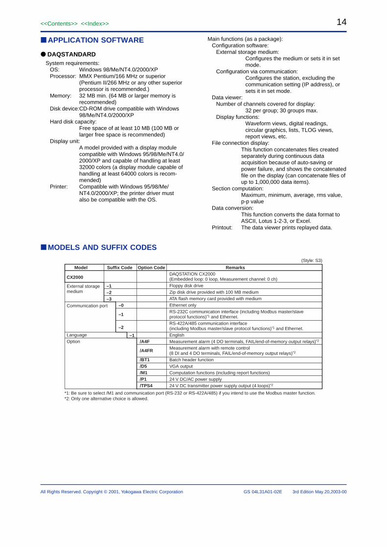
■ APPLICATION SOFTWARE
● DAQSTANDARDSystem requirements:
OS: Windows 98/Me/NT4.0/2000/XPProcessor: MMX Pentium/166 MHz or superior
(Pentium II/266 MHz or any other superiorprocessor is recommended.)
Memory: 32 MB min. (64 MB or larger memory isrecommended)
Disk device:CD-ROM drive compatible with Windows98/Me/NT4.0/2000/XP
Hard disk capacity:Free space of at least 10 MB (100 MB orlarger free space is recommended)
Display unit:A model provided with a display modulecompatible with Windows 95/98/Me/NT4.0/2000/XP and capable of handling at least32000 colors (a display module capable ofhandling at least 64000 colors is recom-mended)
Printer: Compatible with Windows 95/98/Me/NT4.0/2000/XP; the printer driver mustalso be compatible with the OS.
Main functions (as a package):Configuration software:
External storage medium:Configures the medium or sets it in setmode.
Configuration via communication:Configures the station, excluding thecommunication setting (IP address), orsets it in set mode.
Data viewer:Number of channels covered for display:
32 per group; 30 groups max.Display functions:
Waveform views, digital readings,circular graphics, lists, TLOG views,report views, etc.
File connection display:This function concatenates files createdseparately during continuous dataacquisition because of auto-saving orpower failure, and shows the concatenatedfile on the display (can concatenate files ofup to 1,000,000 data items).
Section computation:Maximum, minimum, average, rms value,p-p value
Data conversion:This function converts the data format toASCII, Lotus 1-2-3, or Excel.
Printout: The data viewer prints replayed data.
■ MODELS AND SUFFIX CODES
Suffix Code
–1–2–3
RemarksModel Option Code
/A4F
/A4FR
/BT1 /D5/M1/P1/TPS4
–0
–1
–2
–1
*1: Be sure to select /M1 and communication port (RS-232 or RS-422A/485) if you intend to use the Modbus master function.*2: Only one alternative choice is allowed.
DAQSTATION CX2000(Embedded loop: 0 loop, Measurement channel: 0 ch)Floppy disk driveZip disk drive provided with 100 MB mediumATA flash memory card provided with mediumEthernet onlyRS-232C communication interface (including Modbus master/slave protocol functions)*1 and Ethernet.RS-422A/485 communication interface(including Modbus master/slave protocol functions)*1 and Ethernet. EnglishMeasurement alarm (4 DO terminals, FAIL/end-of-memory output relays)*2
Measurement alarm with remote control(8 DI and 4 DO terminals, FAIL/end-of-memory output relays)*2
Batch header functionVGA outputComputation functions (including report functions)24 V DC/AC power supply24 V DC transmitter power supply output (4 loops)*2
CX2000 External storagemedium
Communication port
LanguageOption
(Style: S3)
15<<Contents>> <<Index>>
All Rights Reserved. Copyright © 2001, Yokogawa Electric Corporation GS 04L31A01-02E 3rd Edition May.20,2003-00
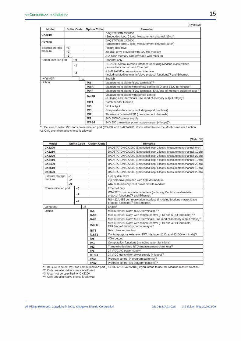
Suffix Code
–1–2–3
RemarksModel Option Code
/A6/A6R/A4F
/A4FR /BT1/D5/M1/N2/P1/TPS4
–0
–1
–2
–1
*1: Be sure to select /M1 and communication port (RS-232 or RS-422A/485) if you intend to use the Modbus master function.*2: Only one alternative choice is allowed.
DAQSTATION CX2000(Embedded loop: 0 loop, Measurement channel: 10 ch)DAQSTATION CX2000(Embedded loop: 0 loop, Measurement channel: 20 ch)Floppy disk driveZip disk drive provided with 100 MB mediumATA flash memory card provided with mediumEthernet onlyRS-232C communication interface (including Modbus master/slave protocol functions)*1 and Ethernet.RS-422A/485 communication interface(including Modbus master/slave protocol functions)*1 and Ethernet. EnglishMeasurement alarm (6 DO terminals)*2
Measurement alarm with remote control (8 DI and 6 DO terminals)*2
Measurement alarm (4 DO terminals, FAIL/end-of-memory output relays)*2
Measurement alarm with remote control(8 DI and 4 DO terminals, FAIL/end-of-memory output relays)*2
Batch header functionVGA outputComputation functions (including report functions)Three-wire isolated RTD (measurement channels)24 V DC/AC power supply24 V DC transmitter power supply output (4 loops)*2
CX2010
CX2020 External storagemedium
Communication port
LanguageOption
(Style: S3)
Suffix Code RemarksModel Option Code
–2
–1–2–3
–0
–1
–2
DAQSTATION CX2000 (Embedded loop: 2 loops, Measurement channel: 0 ch)DAQSTATION CX2000 (Embedded loop: 2 loops, Measurement channel: 10 ch)DAQSTATION CX2000 (Embedded loop: 2 loops, Measurement channel: 20 ch)DAQSTATION CX2000 (Embedded loop: 4 loops, Measurement channel: 10 ch)DAQSTATION CX2000 (Embedded loop: 4 loops, Measurement channel: 20 ch)DAQSTATION CX2000 (Embedded loop: 6 loops, Measurement channel: 10 ch)DAQSTATION CX2000 (Embedded loop: 6 loops, Measurement channel: 20 ch)Floppy disk driveZip disk drive provided with 100 MB mediumATA flash memory card provided with mediumEthernet onlyRS-232C communication interface (including Modbus master/slave protocol functions)*1 and Ethernet.RS-422A/485 communication interface (including Modbus master/slave protocol functions)*1 and Ethernet.EnglishMeasurement alarm (6 DO terminals)*2*3
Measurement alarm with remote control (8 DI and 6 DO terminals)*2*3
Measurement alarm (4 DO terminals, FAIL/end-of-memory output relays)*2
Measurement alarm with remote control (8 DI and 4 DO terminals, FAIL/end-of-memory output relays)*2
Batch header functionControl-purpose extension DIO interface (12 DI and 12 DO terminals)*2
VGA outputComputation functions (including report functions)Three-wire isolated RTD (measurement channels)*3
24 V DC/AC power supply24 V DC transmitter power supply (4 loops)*2
Program control (4 program patterns)*4
Program control (30 program patterns)*4
/A6/A6R/A4F
/A4FR /BT1/CST1/D5/M1/N2/P1/TPS4/PG1/PG2
CX2200CX2210 CX2220 CX2410 CX2420 CX2610 CX2620 External storage medium
Communication port Language
Option
(Style: S3)
*1: Be sure to select /M1 and communication port (RS-232 or RS-422A/485) if you intend to use the Modbus master function.*2: Only one alternative choice is allowed.*3: It can not be specified for CX2200.*4: Only one alternative choice is allowed.
16
All Rights Reserved. Copyright © 2001, Yokogawa Electric Corporation
<<Contents>> <<Index>>
GS 04L31A01-02E 3rd Edition May.20,2003-00
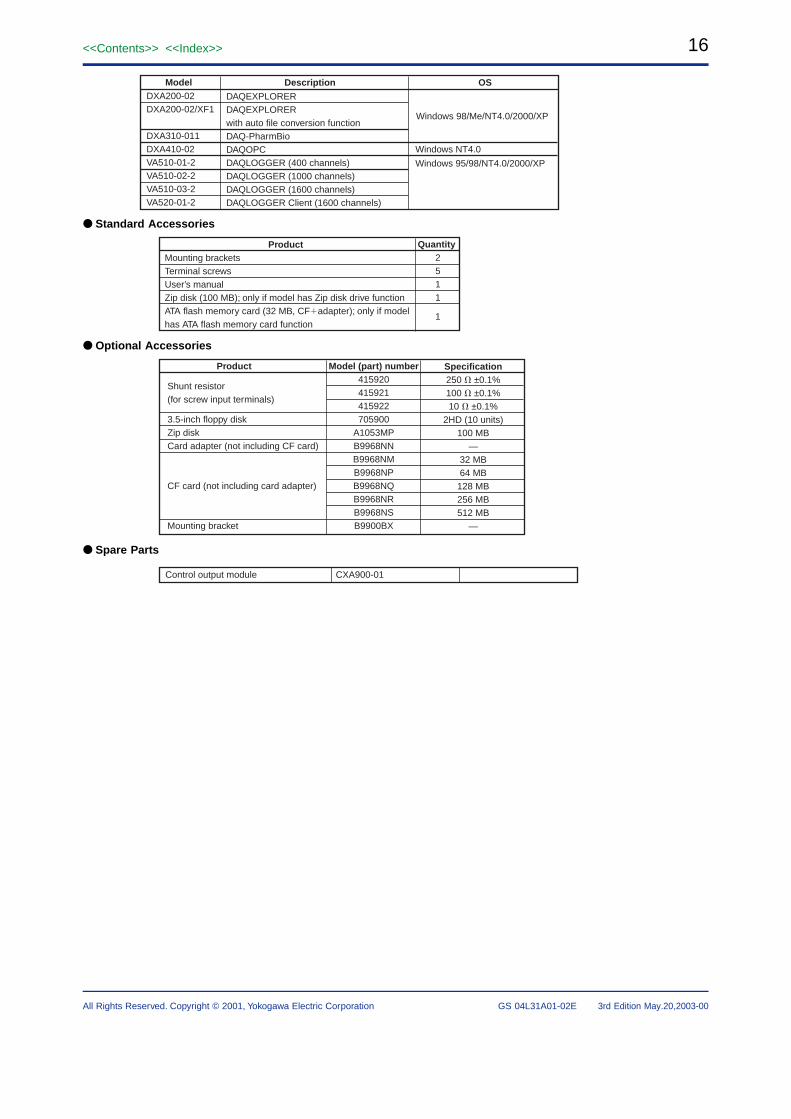
Description OS
DAQEXPLORERDAQEXPLORERwith auto file conversion functionDAQ-PharmBioDAQOPCDAQLOGGER (400 channels)DAQLOGGER (1000 channels)DAQLOGGER (1600 channels)DAQLOGGER Client (1600 channels)
ModelDXA200-02DXA200-02/XF1
DXA310-011DXA410-02VA510-01-2VA510-02-2VA510-03-2VA520-01-2
Windows 98/Me/NT4.0/2000/XP
Windows NT4.0
Windows 95/98/NT4.0/2000/XP
● Standard Accessories
ProductMounting bracketsTerminal screwsUser’s manualZip disk (100 MB); only if model has Zip disk drive functionATA flash memory card (32 MB, CFadapter); only if model has ATA flash memory card function
Quantity2511
1
● Optional Accessories
Specification250 � ±0.1%100 � ±0.1%10 � ±0.1%
2HD (10 units)100 MB
—32 MB64 MB
128 MB256 MB512 MB
—
Model (part) number415920415921415922705900
A1053MPB9968NNB9968NMB9968NPB9968NQB9968NRB9968NSB9900BX
Product
Shunt resistor (for screw input terminals)
3.5-inch floppy diskZip diskCard adapter (not including CF card)
CF card (not including card adapter)
Mounting bracket
● Spare Parts
CXA900-01Control output module
17<<Contents>> <<Index>>
All Rights Reserved. Copyright © 2001, Yokogawa Electric Corporation GS 04L31A01-02E 3rd Edition May.20,2003-00
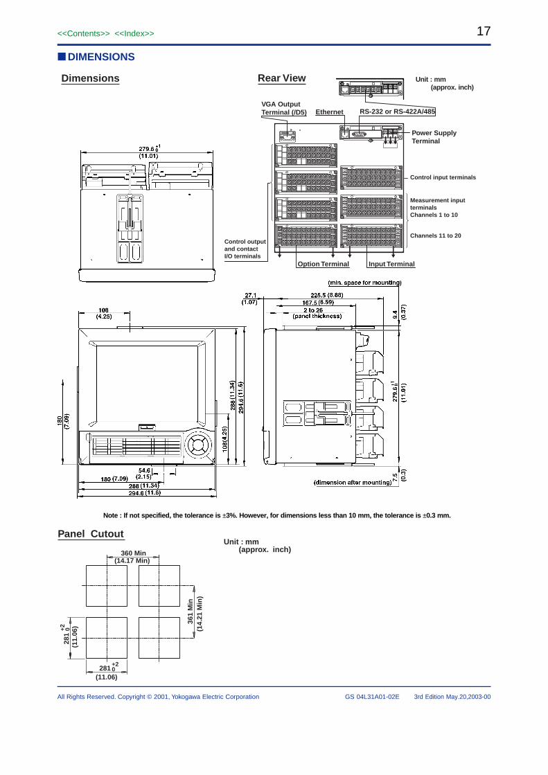
■ DIMENSIONS
Input Terminal
RS-232 or RS-422A/485
Dimensions
Note : If not specified, the tolerance is ±3%. However, for dimensions less than 10 mm, the tolerance is ±0.3 mm.
Control input terminals
Measurement input terminalsChannels 1 to 10
Channels 11 to 20
Option Terminal
Power SupplyTerminal
VGA OutputTerminal (/D5) Ethernet
Rear View Unit : mm(approx. inch)
Control output and contact I/O terminals
361
Min
360 Min(14.17 Min)
(14.
21 M
in)
(11.
06)
(11.06)281
+20
281
+2 0
Panel CutoutUnit : mm (approx. inch)
18
All Rights Reserved. Copyright © 2001, Yokogawa Electric Corporation
<<Contents>> <<Index>>
GS 04L31A01-02E 3rd Edition May.20,2003-00
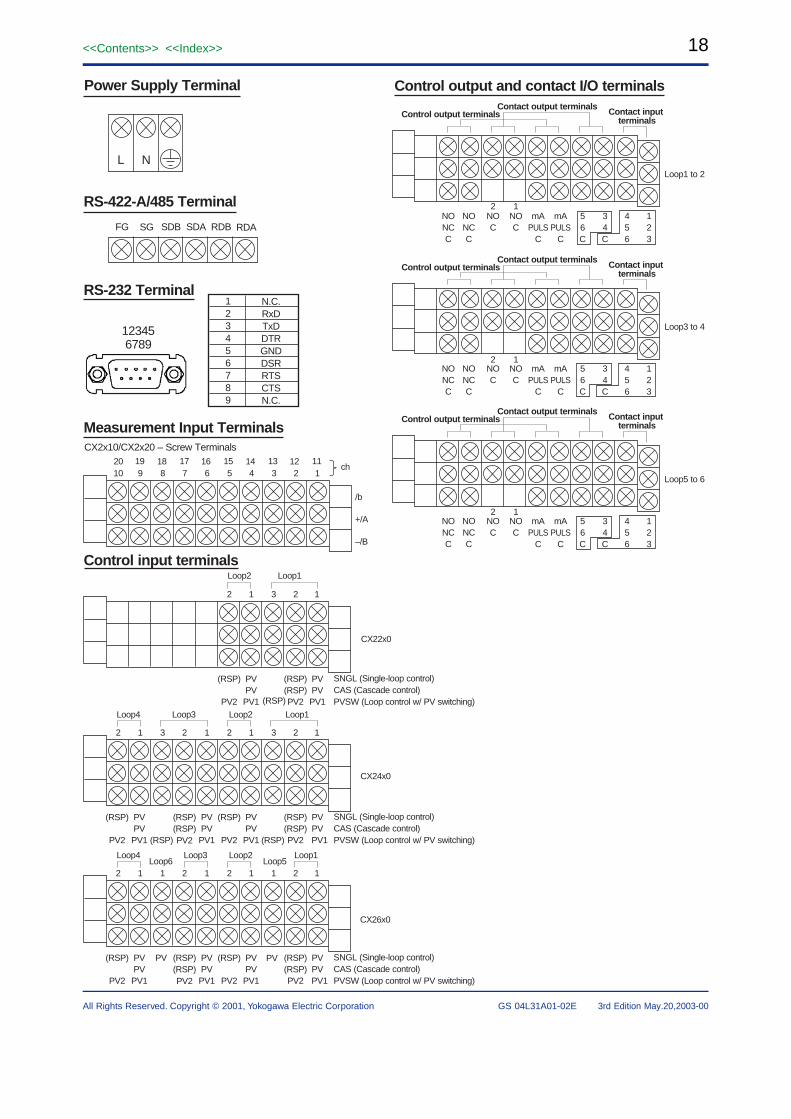
RS-422-A/485 Terminal
RS-232 Terminal
L N
FG SG SDB SDA RDB RDA
123456789
N.C.RxDTxDDTRGNDDSRRTSCTSN.C.
12345 6789
Power Supply Terminal Control output and contact I/O terminals
Control output terminalsContact output terminals Contact input
terminals
Control output terminalsContact output terminals Contact input
terminals
Control output terminalsContact output terminals Contact input
terminals
Loop1 to 2
1435mAmANONO12
NO2546PULSPULSCCNC36CCCCC
NONCC
Loop3 to 4
1435mAmANONO12
2546PULSPULSCC36CCCC
Loop5 to 6
1435mAmANONO12
2546PULSPULSCC36CCCC
NONCC
NONCC
NONCC
NONCC
Measurement Input TerminalsCX2x10/CX2x20 – Screw Terminals
ch
/b
+/A
–/B
1122345678910
1114 1316 1518 1720 19
Control input terminalsLoop2 Loop1
1
SNGL (Single-loop control)CAS (Cascade control)PVSW (Loop control w/ PV switching)
2312
PV(RSP)PV(RSP)PV(RSP)PV
(RSP) PV1PV2PV1PV2
CX22x0
Loop4Loop6
Loop3 Loop2Loop5
Loop1
1
SNGL (Single-loop control)CAS (Cascade control)PVSW (Loop control w/ PV switching)
211212112
PV(RSP)PV PV(RSP)PV(RSP)PV PV(RSP)PV(RSP)PVPV(RSP)
PV2PV
PV1PV2PV1PV2PV1PV1PV2
CX26x0
CX24x0
Loop4 Loop3 Loop2 Loop1
1
SNGL (Single-loop control)CAS (Cascade control)PVSW (Loop control w/ PV switching)
231212312
PV(RSP)PV(RSP)
(RSP)
PV(RSP)PV(RSP)
(RSP)PV(RSP)PVPV(RSP)
PV2PV
PV1PV2PV1PV2PV1PV1PV2
19<<Contents>> <<Index>>
All Rights Reserved. Copyright © 2001, Yokogawa Electric Corporation GS 04L31A01-02E 3rd Edition May.20,2003-00
11
12
C
10
11
12
C
C
C
4
5
6
7
8
9
5
6
C
7
8
C
9
10
C
1
2
3
4
1
2
3
DO block, 12 terminals DI block, 12 terminals
/CST1
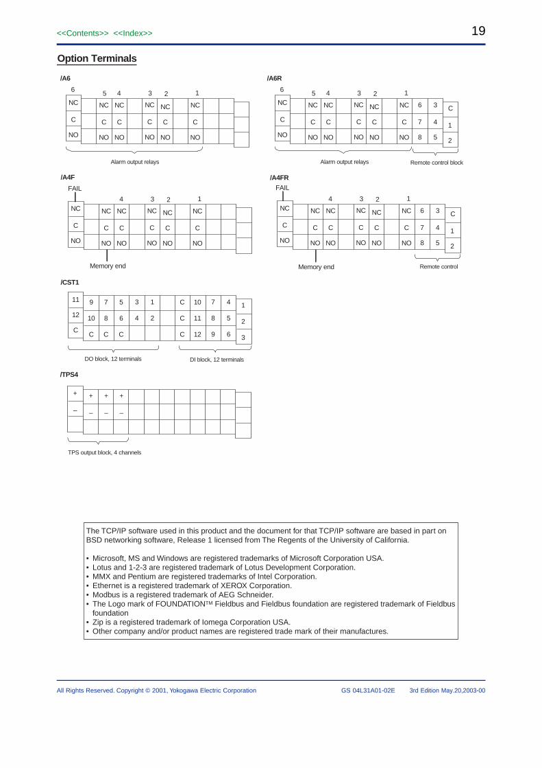
Option Terminals
123456
NC
C
NO
NC
C
NO
NC
C
NO
NC
C
NO
NC
C
NO
NC
C
NO
Alarm output relays
123456
NC
C
NO
NC
C
NO
NC
C
NO
NC
C
NO
NC
C
NO
NC
C
NO
3
4
5
6
7
8
C
1
2
Alarm output relays Remote control block
Remote control
/TPS4
+
–
+
–
+
–
+
–
TPS output block, 4 channels
/A6 /A6R
/A4F /A4FR
1234
Memory end Memory end
FAIL
NC
C
NO
NC
C
NO
NC
C
NO
NC
C
NO
NC
C
NO
NC
C
NO
1234NC
C
NO
NC
C
NO
NC
C
NO
NC
C
NO
NC
C
NO
NC
C
NO
3
4
5
6
7
8
C
1
2
FAIL
The TCP/IP software used in this product and the document for that TCP/IP software are based in part on BSD networking software, Release 1 licensed from The Regents of the University of California.
• Microsoft, MS and Windows are registered trademarks of Microsoft Corporation USA.• Lotus and 1-2-3 are registered trademark of Lotus Development Corporation.• MMX and Pentium are registered trademarks of Intel Corporation.• Ethernet is a registered trademark of XEROX Corporation.• Modbus is a registered trademark of AEG Schneider.• The Logo mark of FOUNDATIONTM Fieldbus and Fieldbus foundation are registered trademark of Fieldbus
foundation• Zip is a registered trademark of Iomega Corporation USA.• Other company and/or product names are registered trade mark of their manufactures.