Embed Size (px)
Citation preview

5/4
Control and signalling units for safety applications 5 Foot switches, Harmony type XPE
Presentation Foot switches type XPE are an ideal solution for providing start and stop instructions for many types of industrial machines, running in various operating modes: normal (pulsed) start, inching, hold to run.
The range comprises metal case foot switches (heavy duty, high risk) complying to very strict regulations, and plastic case foot switches (light duty, low risk).
Fitted with a protective cover, the foot switches are for applications where, for each issuing of the start instruction, a high level of danger exists (high risk).
Foot switches without a protective cover are suitable for applications where the issuing of the start instruction presents a reduced level of danger.
Contact
Switches incorporate snap action contacts with positive opening operation
The foot switches can incorporate one or two N/C + N/O contact blocks.
Positive opening operation on release of pedal: the hold down or return to the rest position of the pedal (machine stop) is positive acting.
Terminology Positive opening operation
A switch meets this requirement when all its N/C contacts can be switched to the open position with certainty, i.e. there are no flexible links between the moving contacts and the actuator to which the operating force is applied.
All pedal operated foot switches incorporate a snap action N/C + N/O contact block with positive opening operation, and conform fully to standard IEC 60947-5- Section 3.
Snap action contact (quick break)
The displacement speed of the moving contacts is not related to the speed at which the contact actuator is operated. This feature gives consistent electrical performance, even when the contact actuator device is operated at low speeds.
General 5
Characteristics:pages 5/8 and 5/22
References:pages 5/9 and 5/23
Dimensions:pages 5/2 and 5/24
1
2
3
4
5
6
7
8
9
10

5/5
Control and signalling units for safety applications 5 Foot switches, Harmony type XPE
Start instructions Foot switches XPE with protective cover are ideally suited for issuing a safety “Start” instruction for potentially dangerous machines.
The protective cover over the operating pedal avoids the risk of accidental operation, either by human action or by falling objects, which could result in unintentional starting of the machine.
A trigger mechanism (toe plate) enables locking of the pedal in the rest (released) position.
Positive action is required on the toe plate 1 before the pedal 2 can be depressed to start the machine.
On releasing the pedal to stop the machine, the trigger mechanism re-engages and locks the pedal in the rest position.
Normal stop instructions
All foot switches of the XPE range can be used for issuing a normal stop instruction to a machine.
Never use the protective cover nor the trigger mechanism for this type of application. Access to the stop control must be as unrestricted as possible and without any constraints.
For machine stop instructions, use the N/C contact(s).
1
2
plastic
metal
toe plate
Stop/rest Start
1
2
plastic
metal
toe plate
Stop/rest Start
General(continued) 5
Characteristics:pages 5/8 and 5/22
References:pages 5/9 and 5/23
Dimensions:pages 5/2 and 5/24
1
2
3
4
5
6
7
8
9
10

5/6
Control and signalling units for safety applications 5 Foot switches, Harmony type XPE
Pedal latching device when depressed
Foot switches with pedal latching device are particularly suited for the control of “hold to run” machines and also, for adjustment operations.
Pressing the pedal issues the machine start instruction and, when the pedal reaches its stop, it latches in the operated position.
Removing the foot from the pedal will not stop the “machine” cycle (hold to run), the pedal remains latched.
For issuing a normal stop instruction, the foot is replaced on the pedal and the toe plate operated: this returns the pedal to the rest position.
Switches with 2 step contact operation
Foot switches featuring 2 step contact operation are ideal for applications involving 2-speed machines. Examples:
First speed: low (used for setting-up, adjustment or tool maintenance).Second speed: fast (normal machine operating speed).
bb
The first step, at 6 mm pedal travel and light foot pressure (2 daN), actuates a N/C + N/O contact block.
The second step, at maximum pedal travel (2 mm) and required foot pressure (9 daN), actuates a second N/C + N/O contact block.
Applications Many types of machines are fitted with foot switches
Bending machineDosing machineAssembly stationPackaging machinesCutting presses, stamping pressesMachine tools (numerical control, lathes, milling machines, grinders, machining
centres)Guillotines, cutters, folders, sawsForging machines, rolling machines, cold metal forming machines
bbbbbb
bb
6mm
9,5mm
2,5 daN.2 daN.1st step
6mm
9,5mm
2,5 daN.2 daN.1st step
12mm
16,5mm
1 daN. 7 daN.2nd step
12mm
16,5mm
1 daN. 7 daN.2nd step
General(continued) 5
Characteristics:pages 5/8 and 5/22
References:pages 5/9 and 5/23
Dimensions:pages 5/2 and 5/24
1
2
3
4
5
6
7
8
9
10
5/7
Control and signalling units for safety applications 5 Foot switches, Harmony type XPE
Foot switches used in conjunct- ion with two-hand control stations
Foot switches XPE can be mounted directly on the baseplate (without drilling additional fixing holes) of the pedestal XY2 SB90 for two-hand control stations XY2 SB7p.
The baseplate of the two-hand control station pedestal XY2 SB90 is pre-drilled with fixing holes to suit the mounting of either:
One XPE foot switch, with or without protective cover.
Two XPE R foot switches, each with its own protective cover or fitted with a common (double) cover.
b
b
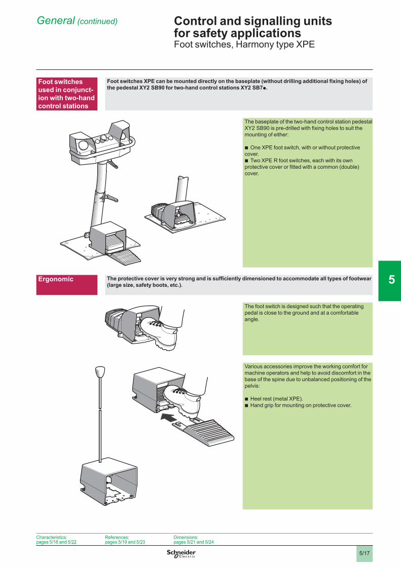
Ergonomic The protective cover is very strong and is sufficiently dimensioned to accommodate all types of footwear (large size, safety boots, etc.).
The foot switch is designed such that the operating pedal is close to the ground and at a comfortable angle.
Various accessories improve the working comfort for machine operators and help to avoid discomfort in the base of the spine due to unbalanced positioning of the pelvis:
Heel rest (metal XPE).Hand grip for mounting on protective cover.
bb
General(continued) 5
Characteristics:pages 5/8 and 5/22
References:pages 5/9 and 5/23
Dimensions:pages 5/2 and 5/24
1
2
3
4
5
6
7
8
9
10

5/8
Control and signalling units for safety applicationsMetal foot switches, Universal, Harmony types XPE M/R
EnvironmentConformity to standards Without protective cover EN/IEC 60947-5-1, CSA C22 2 n° 14 (if H2 specified)
With protective cover NF E 09-03Product certifications Standard version FI, CSA A300 - Q300 with tapped entries for cable gland
Special version CSA A300 - Q300 with 1/2” NPT adaptorProtective treatment Standard version “TC”
Special version “TH”Ambient air temperature For operation °C - 25…+ 70
For storage °C - 40…+ 70Vibration resistance 15 gn (10…500 Hz) conforming to IEC 60068-2-6Shock resistance 20 gn conforming to IEC 60068-2-27 (50 gn conforming to NF E 09-03)Electric shock protection Class I conforming to EN/IEC 640 and NF C 20-030Mechanical life 5 million operating cyclesDegree of protection IP 66 conforming to IEC 60529 and IP 669 conforming to NF C 20-00 (with protective
cover)Cable entries See dimensions, page 5/2
Contact block characteristicsRated operational characteristics
a AC-5 A300 or Ue = 240 V, Ie = 3 Ac DC-3 Q300 or Ue = 250 V, Ie = 0.27 A conforming to EN/IEC 60947-5- Appendix A
Rated insulation voltage V Ui = 500, degree of pollution 3 conforming to EN/IEC 60947-, group C conforming to NF C 20-040 and VDE 00Ui = 300 conforming to UL 508, CSA C22-2 n° 4
Rated impulse withstand voltage kV Uimp = 6 conforming to EN/IEC 60947-
Positive operation N/C contact with positive opening operation conforming to EN/IEC 60947-5- Appendix K
Resistance across terminals mΩ y 25 conforming to NF C 93-050 method A or IEC 60255-7 category 3Short-circuit protection 0 A cartridge fuse type gG (gl) conforming to EN/IEC 60947-5-, VDE 0660-200Foot switches with snap action contacts
Operational power Conforming to EN/IEC 60947-5- Appendix CUtilisation categories AC-5 and DC-3Operating rate 3600 operating cycles/hour. Load factor: 0.5
a.c. supply a 50-60 Hz d.c. supply co Inductive circuit Power broken in W for 5 million operating
cyclesVoltage V 24 48 20o W 0 7 4
Foot switches with analogue output
Nominal supply voltage V c 24…48Voltage limits V c 9…58Current consumption, no-load mA 4Output current drift (IS) in relation to temperature
0…+ 50 °C: + 2…- 6%- 25…+ 70 °C: + 2…- 2%
Output current curve Wiring scheme
Connection Screw clamp terminals Maximum clamping capacity: x 2.5 mm2 or 2 x .5 mm2 with or without cable end
5
1
0,5
0,10,1 1 2 3 4 5 10
Ithe
48 V
24 V
400 V
230 V
110 V
Current in A
Mill
ions
of o
pera
ting
cycl
es 5
1
0,5
0,10,1 1 2 3 4 5 10
Ithe
48 V
24 V
400 V
230 V
110 V
Current in A
Mill
ions
of o
pera
ting
cycl
es
0
1
2 5 10 15
2
3
4
5
0
Current (mA)
Change of contact state
Pedal travel
(mm)0
1
2 5 10 15
2
3
4
5
0
Current (mA)
Change of contact state
Pedal travel
(mm)
1
2
+
–R
ImA3
BN (brown)
BK (black)
BU (blue)
1
2
+
–R
ImA3
BN (brown)
BK (black)
BU (blue)
General: page 5/4
References:page 5/9
Dimensions:page 5/2
General: page 5/4
References:page 5/9
Dimensions:page 5/2
General: page 5/4
References:page 5/9
Dimensions:page 5/2
General: page 5/4
References:page 5/9
Dimensions:page 5/2
Characteristics 5
2
1
3
4
5
6
7
8
9
10
2
1
3
4
5
6
7
8
9
10
2
1
3
4
5
6
7
8
9
10
2
1
3
4
5
6
7
8
9
10

5/9
Control and signalling units for safety applicationsMetal foot switches, Universal, Harmony types XPE M/R
Single and double pedal foot switches with protective coverDescription Pedal Contact operation Colour Reference Weight
kgMetalWith trigger mechanism requiring positive action to allow pedal operation
Single step N/C + N/O Blue XPE M510 2.570
Double step 2 x N/C + N/O Blue XPE M5100D 6.070
Single step N/C + N/O Orange XPE R510 2.570
Double step 2 x N/C + N/O Orange XPE R5100D 6.070
Single step 2 N/C + N/O Blue XPE M511 2.590
Double step 2 x 2 N/C + N/O Blue XPE M5110D 6.090
Single step 2 N/C + N/O Orange XPE R511 2.590
Double step 2 x 2 N/C + N/O Orange XPE R5110D 6.090
Single 2 step 2 N/C + N/O Blue XPE M711 2.590
Orange XPE R711 2.590
Single step with analogue output
2 N/C + N/O Blue XPE M529 2.600
Orange XPE R529 2.600
MetalWithout trigger mechanism
Single step N/C + N/O Blue XPE M310 2.400
Double step 2 x N/C + N/O Blue XPE M3100D 5.900
Single step N/C + N/O Orange XPE R310 2.400
Double step 2 x N/C + N/O Orange XPE R3100D 5.900
Single step 2 N/C + N/O Blue XPE M311 2.420
Double step 2 x 2 N/C + N/O Blue XPE M3110D 5.920
Single step 2 N/C + N/O Orange XPE R311 2.420
Double step 2 x 2 N/C + N/O Orange XPE R3110D 5.920
Single step latching N/C + N/O Blue XPE M410 2.400
Orange XPE R410 2.420
Single 2 step 2 N/C + N/O Blue XPE M611 2.420
Orange XPE R611 2.420
Single step with analogue output
2 N/C + N/O Blue XPE M329 2.420
Double 2 step + step
2 x N/C + N/O + N/C + N/O
Blue XPE M6210D 5.900
XPEM510
523
48
XPEM510
523
48
XPER5100D
523
50
XPER5100D
523
50
XPEM310
523
47
XPEM310
523
47
XPER3100D
523
49
XPER3100D
523
49
General: page 5/6
Characteristics:page 5/8
Dimensions:page 5/2
General: page 5/6
Characteristics:page 5/8
Dimensions:page 5/2
General: page 5/6
Characteristics:page 5/8
Dimensions:page 5/2
General: page 5/6
Characteristics:page 5/8
Dimensions:page 5/2
References 5
2
1
3
4
5
6
7
8
9
10
2
1
3
4
5
6
7
8
9
10
2
1
3
4
5
6
7
8
9
10
2
1
3
4
5
6
7
8
9
10

5/20
Control and signalling units for safety applicationsMetal foot switches, Universal, Harmony types XPE M/R
Foot switches without protective coverDescription Contact operation Colour Reference Weight
kgMetalWith trigger mechanism requiring positive action to allow pedal operation
step N/C + N/O Blue XPE M810 .200Orange XPE R810 .200
2 N/C + N/O Blue XPE M811 .220Orange XPE R811 .220
2 step 2 N/C + N/O Blue XPE M911 .220Orange XPE R911 .220
Analogue output 2 N/C + N/O Blue XPE M929 .220Orange XPE R929 .220
MetalWithout trigger mechanism
step N/C + N/O Blue XPE M110 (1) .200Orange XPE R110 (1) .200
2 N/C + N/O Blue XPE M111 (1) .220Orange XPE R111 (1) .220
2 step 2 N/C + N/O Blue XPE M211 (1) .220Orange XPE R211 (1) .220
Analogue output 2 N/C + N/O Orange XPE R229 .220
AccessoriesDescription For use with Unit reference Weight
kgSingle protective cover XPE M XPE Z901 .200
XPE R XPE Z911 .200
Double protective cover XPE M XPE Z921 .200
XPE R XPE Z931 .200
Hand grip for protective cover
XPE Z901 or XPE Z911 XPE Z913 0.450
Heel rest XPE M XPE Z902 0.240
XPE R XPE Z912 0.240
Trigger mechanism XPE M or XPE R XPE Z903 0.70
Latching device (replacement for foot switches with this feature)
XPE M or XPE R XPE Z904 0.70
Cable clamp XPE M or XPE R XPE Z905 0.00
Contact blocks Snap action
step switches: st or 2nd N/C + N/O2 step switches: st N/C + N/O
XE2S P4151 0.020
2 step switches: 2nd N/C + N/O XE2S P4151B 0.020
ISO M20 adaptor(Sold in lots of 5)
XPE M or XPE R DE9 RA1620 0.050
(1)ToorderanATEXDversionoftheproduct(protectionagainstdust),addEXtotheendofthereference.Example:XPE M110EX.
XPER810
523
46
XPER810
523
46
XPEM110
523
45
XPEM110
523
45
XPEZ901
5808
05
XPEZ901
5808
05
XPEZ902
5808
06
XPEZ902
5808
06
XE2SP4151p
5509
78
XE2SP4151p
5509
78
General: page 5/6
Characteristics:page 5/8
Dimensions:page 5/2
General: page 5/6
Characteristics:page 5/8
Dimensions:page 5/2
General: page 5/6
Characteristics:page 5/8
Dimensions:page 5/2
General: page 5/6
Characteristics:page 5/8
Dimensions:page 5/2
References(continued) 5
2
1
3
4
5
6
7
8
9
10
2
1
3
4
5
6
7
8
9
10
2
1
3
4
5
6
7
8
9
10
2
1
3
4
5
6
7
8
9
10

5/2
Control and signalling units for safety applicationsMetal foot switches, Universal, Harmony types XPE M/R
XPE M, XPE R without protective cover
XPE M, XPE R with protective cover XPE Z913
Single
Double
a bSingle pedal 52 60Double pedal 55 295(1)2tappedentriesforn°16(Pg16)cablegland.ForISOM20,useadaptorDE9RA1620.(2)1Ø6plainhole.
59
164
22,5
146,5 8,5
(1)
8
=
31 104
=
172
3XØ9
=
=89
,5
107
59
164
22,5
146,5 8,5
(1)
8
=
31 104
=
172
3XØ9
=
=89
,5
107
172,5
a
146,5
10,5
137
16,5
14,5
(1)
29
172,5
a
146,5
10,5
137
16,5
14,5
(1)
29
164=
674
b
87
=Ø 40
Ø 10
(2)
164=
674
b
87
=Ø 40
Ø 10
(2)
186
3XØ9
31
=89
,5=
135
==
160
186
3XØ9
31
=89
,5=
135
==
160
190
4XØ9
11,7
5
==
295
6767
11,7
5
190
4XØ9
11,7
5
==
295
6767
11,7
5
Dimensions 5
2
1
3
4
5
6
7
8
9
10
2
1
3
4
5
6
7
8
9
10
2
1
3
4
5
6
7
8
9
10
2
1
3
4
5
6
7
8
9
10

5/22
Control and signalling units for safety applicationsPlastic foot switches, Harmony types XPE A/B/G/Y
EnvironmentConformity to standards
XPE A, XPE B, XPE G, XPE Y without protective cover: IEC/EN 60947-5-XPE B, XPE G: UL 508, CSA C22-2 n° 4XPE B, XPE G with protective cover: NF E 09-03
Product certifications Standard version
XPE B, XPE G: UL, CSA A300 - Q300 with knock-out entries for ISO M20 cable gland
Protective treatment Standard version “TH”
Ambient air temperature For operation °C XPE B, XPE G: - 25…+ 70 XPE A, XPE Y: - 25…+ 55
For storage °C - 40…+ 70
Vibration resistance Conforming to IEC 60068-2-6 5 gn (10…500 Hz)
Shock resistance Conforming to IEC 60068-2-27 XPE A: 25 gn, XPE B, XPE G, XPE Y: 30 gnElectric shock protection Conforming to IEC/EN 640
and NF C 20-030Class II
Mechanical life
XPE A: 2 million operating cyclesXPE Y: 5 million operating cyclesXPE B, XPE G: 0 million operating cycles
Degree of protection
XPE A: IP 43 conforming to IEC 60529XPE Y: IP 55 conforming to IEC 60529XPE B, XPE G: IP 66 conforming to IEC 60529
Cable entries See dimensions, pages 5/24 and 5/25
Contact block characteristicsRated operational characteristics
a AC-5; A 300 or Ue = 240 V, Ie = 3 Ac DC-3; Q 300 or Ue = 250 V, Ie = 0.27 A conforming to IEC/EN 60947-5- Appendix A
Rated insulation voltage
Ui = 500 V degree of pollution 3 conforming to IEC/EN 60947-, group C conforming to NF C 20-040 and VDE 00Ui = 300 V conforming to UL 508, CSA C22-2 n° 4
Rated impulse withstand voltage Uimp = 6 kV conforming to IEC/EN 60947-
Positive operation N/C contact with positive opening operation conforming to IEC/EN 60947-5- Appendix K
Resistance across terminals ≤ 25 mΩ conforming to NF C 93-050 method A or IEC 60255-7 category 3
Short-circuit protection 0 A cartridge fuse type gG (gl) conforming to IEC/EN 60947-5-, VDE 0660-200
Operational powerconforming to IEC/EN 60947-5- Appendix C
Foot switches with snap action contactsUtilisation categories AC-5 and DC-3Operating rate: 3600 operating cycles/hourLoad factor: 0.5a.c. supply a 50-60 Hzo Inductive circuit
d.c. supply cPower broken in W for 5 million operating cycles
Voltage V 24 48 20o W 0 7 4
Connection Screw clamp terminalsMaximum clamping capacity: x 2.5 mm2 or 2 x .5 mm2 with or without cable end
5
1
0,5
0,10,1 1 2 3 4 5 10
Ithe
48 V
24 V
400 V
230 V
110 V
Current in A
Mill
ions
of o
pera
ting
cycl
es 5
1
0,5
0,10,1 1 2 3 4 5 10
Ithe
48 V
24 V
400 V
230 V
110 V
Current in A
Mill
ions
of o
pera
ting
cycl
es
General: page 5/4
References:page 5/23
Dimensions:page 5/24
General: page 5/4
References:page 5/23
Dimensions:page 5/24
General: page 5/4
References:page 5/23
Dimensions:page 5/24
General: page 5/4
References:page 5/23
Dimensions:page 5/24
Characteristics 5
1
2
3
4
5
6
7
8
9
10

5/23
Control and signalling units for safety applicationsPlastic foot switches, Harmony types XPE A/B/G/Y
Single pedal foot switches with protective coverDescription Contact operation Housing
colourReference Weight
kgWith trigger mechanism requiring positive action to allow pedal operation
step N/C + N/O Yellow XPE Y510(1) 0.700Blue XPE B510 0.700Grey XPE G510 0.700
2 N/C + N/O Yellow XPE Y511 (1) 0.700Blue XPE B511 0.700Grey XPE G511 0.700
2 step 2 N/C + N/O Yellow XPE Y711 (1) 0.700Blue XPE B711 0.700Grey XPE G711 0.700
Without trigger mechanism
step N/C + N/O Yellow XPE Y310 0.690Blue XPE B310 0.690Grey XPE G310 0.690
2 N/C + N/O Yellow XPE Y311 (1) 0.690Blue XPE B311 0.690Grey XPE G311 0.690
2 step 2 N/C + N/O Yellow XPE Y611 (1) 0.690Blue XPE B611 0.690Grey XPE G611 0.690
Foot switches without protective coverDescription Contact operation Housing
colourReference Weight
kgWith trigger mechanism requiring positive action to allow pedal operation
step N/C + N/O Grey XPE G810 0.580
2 step 2 N/C + N/O Grey XPE G911 0.580
Without trigger mechanism
step N/C + N/O Yellow XPE Y110 (1) 0.570Blue XPE B110 0.570Grey XPE G110 0.570Black XPE A110 0.275
2 N/C + N/O Blue XPE B111 0.570Grey XPE G111 0.570Black XPE A111 0.295
2 step 2 N/C + N/O Yellow XPE Y211 (1) 0.570Blue XPE B211 0.570Grey XPE G211 0.570
Accessories for foot switches, with or without protective coverDescription For use with Sold in
lots ofUnit reference Weight
kgM20 x 1.5 cable gland
Cable Ø 5…0 mm 5 DE9RA200612 0.04
Cable Ø 7…3 mm 5 DE9RA201014 0.04
Contact blocks, snap action
or 2 step switches
XE2S P4151 0.020
(1)IP55,notUL,CSAapproved.
XPEp510
XPEp310
XPEp510
XPEp310
XPEG810
XPEp110
XPEA110
XPEG810
XPEp110
XPEA110
XE2SP4151XE2SP4151
General: page 5/4
Characteristics:page 5/22
Dimensions:page 5/24
General: page 5/4
Characteristics:page 5/22
Dimensions:page 5/24
General: page 5/4
Characteristics:page 5/22
Dimensions:page 5/24
General: page 5/4
Characteristics:page 5/22
Dimensions:page 5/24
References 5
1
2
3
4
5
6
7
8
9
10

5/24
Control and signalling units for safety applicationsPlastic foot switches, Harmony types XPE B/G/Y
XPE B, XPE G, XPE Y With protective cover
(1)Ø16x4counterboredhole.(2) 4 cover fixing screws: stainless steel. Tightening torque: 1 N.m.
Without protective cover
(1)2plainholesforISOM20orn°13(Pg13.5)cablegland.(2) 4 cover fixing screws: stainless steel. Tightening torque: 1 N.m.(3)Returnspring:stainlesssteel.
154
165
141
282
122
(1)(2)
154
165
141
282
122
(1)(2)
50
7416
5
141
282
122 39= =
(1)
31
(2)
(3) 50
7416
5
141
282
122 39= =
(1)
31
(2)
(3)
General: page 5/4
Characteristics: page 5/22
References:page 5/23
General: page 5/4
Characteristics: page 5/22
References:page 5/23
General: page 5/4
Characteristics: page 5/22
References:page 5/23
General: page 5/4
Characteristics: page 5/22
References:page 5/23
Dimensions 5
1
2
3
4
5
6
7
8
9
10

5/25
Control and signalling units for safety applicationsPlastic foot switches, Harmony type XPE A
XPE A
(1)1plainholeforISOM20orn°13(Pg13.5)cablegland.(2)1plainholeforISOM20orn°9(Pg11)cablegland.
5454
6
23
94=
=
6
28
(1)
(2)
5454
6
23
94=
=
6
28
(1)
(2)
General: page 5/4
Characteristics: page 5/22
References:page 5/23
General: page 5/4
Characteristics: page 5/22
References:page 5/23
General: page 5/4
Characteristics: page 5/22
References:page 5/23
General: page 5/4
Characteristics: page 5/22
References:page 5/23
Dimensions 5
1
2
3
4
5
6
7
8
9
10