Embed Size (px)
Citation preview

GENERAL CATALOGUE
Photovoltaic solutions
2012


Inverters02 Socomec Group
Serving your power
10 SUNSYS H30i
11 SUNSYS H50
14 SUNSYS B10
15 SUNSYS B15
16 SUNSYS B20
17 SUNSYS B30
20 SUNSYS R01 - R02
21 SUNSYS P03+T03
22 SUNSYS P02
23 SUNSYS P03
Equipment24 SUNSYS Shelter
28 SIRCO PV
30 Fuses, fuse bases PV
31 SURGYS PV
Monitoring.32 Intelligent Field Box
36 DIRIS
37 SUNGUARD monitoring
38 Inverter technology
40 Summary of photovoltaic systems
pp
gg
Fixed for residential use
Solar parks
Buildings
Contents
1

2
SOCOMEC, founded in 1922,
is an industrial group with a
workforce of 3000 people.
Our core business: the availability,
control and safety of low-voltage
electrical networks with increasing
attention given to the characteristics
of customer power supplies.
CO
RP
O 3
08 A
The culture of independence
THE independence of the SOCOMEC group guarantees control of the entire decision-making process, in accordance with the values promoted by family shareholders and shared by employees.
With about 30 branches spread over all five continents, SOCOMEC pursues international development by concentrating on applications for the industrial and service sectors, where the quality of experience makes the difference.
Spirit of innovation
SOCOMEC, the undisputed specialist in UPS systems, switching power supplies and power conversion and metering systems, invests almost 10 % of its revenue in Research and Development. This makes it possible for the group to fulfill its ambition of being constantly at the cutting-edge of technology.
The opinion of a specialist
SOCOMEC is a manufacturer that has total control of its technological processes, making it very different to most other suppliers. The group is constantly improving its specialist skills and knowledge in order to provide its customers with increasingly customised solutions.
Flexible organisation
The group, based on two centres of excellence in Europe (France and Italy), also has competitive production sites in countries such as Tunisia and branches in the main emerging markets (India and China).
All these sites adhere to a policy of ongoing improvement based on Lean Manufacturing principles and are therefore ideally placed to meet high quality standards and comply with the timescales and cost levels demanded by customers.
Attention to service
Our manufacturing experience naturally extends to a complete range of services designed to facilitate the selection, implementation and use of our solutions. Our service teams have built up a reputation by providing consultations and flexible skills, and responding promptly.
Responsible growth
As A GROUP which welcomes all cultures and is firmly committed to human values, Socomec encourages the initiative and efforts of its employees. Working relationships are based on partnerships and shared ethical principles. As part of its commitment to lasting and stable development, SOCOMEC fully assumes its responsibilities as a company, not only to its shareholders, employees, customers and partners, but also to society as a whole and the environment.
SOCOMEC has been a supporter of Global Compact since 2003.
SOCOMEC Group An independent manufacturer
the power of a specialist

3
Power control and safety
Managing power and protecting individuals and material assets.
SOCOMEC's experience in this area is indisputable; its leadership in the field of power disconnection and switching applications is unrivalled and it has been a specialist manufacturer of electrical equipment since1922. The company has long been an advocate of the benefits of protecting people and material assets with the use of fuses and has assumed a key role in the development of cutting-edge technologies, such as the monitoring and detection of insulation defects.
SOCOMEC guarantees solutions and services that are both valid and efficient.
Critical power
Ensuring the availability of high quality power for critical applications.
Thanks to its wide range of constantly evolving products, SOCOMEC has considerable experience in the three essential technologies that guarantee the high availability of power supplies for critical installations and buildings. These are:
• Uninterruptible Power Supply (UPS) systems that provide high quality power and reduce power supply distortion and outage thanks to the autonomy of energy storage devices,
• high-availability power source switching for the transfer of power to an operational reserve power source,
• constant monitoring of systems to prevent failures and limit operational downtime.
Energy efficiency
Improving the energy efficiency of buildings and systems
The solutions provided by SOCOMEC, ranging from sensors to a vast range of innovative modular software packages, are managed by energy efficiency experts and satisfy the main requirements of people responsible for industrial buildings and workers in industry, services and local government, making it possible to:
• measure power absorption, identify excessive absorption sources and increase occupant awareness,
• limit reactive power and prevent the related penalties,
• get the benefit of the best tariffs, check billing to suppliers and divide power consumption costs correctly between users.
Solar power
Guaranteeing the safety and reliability of photovoltaic systems (PV).
As an expert in the provision of equipment for the use of solar energy, SOCOMEC has the specialist skills required for the introduction of fundamental strategic functions into photovoltaic systems, which include:
• safety, with the use of load-break switches specially designed to break the direct current generated by solar panels regardless of system configuration and operating conditions,
• the reliability of direct current systems thanks to solutions that prevent the deterioration of insulation and direct current arc failures,
• highly efficient power conversion control with PV inverter, for transforming all the power generated by solar panels into power that can either be consumed locally or put back into the national grid.
Four key applications: the skill of a specialist

4
Indispensable skills
The conversion of power generated by PV panels and connection to systems in the electricity grid is a factor that should be taken into consideration by anyone wishing to renew their electrical power systems with the integration of photovoltaic solar energy.
Special skills are needed if the optimum efficiency and long life of the system are to be guaranteed, with regard to the specificity of the installation and the electrical parameters brought into play.
Controlled specialisations
SOCOMEC SOLAR, a fully fledged Socomec Group skill centre, brings together all the skills needed to ensure perfect control of the main general principles of photovoltaic architecture. The solution, downstream of the panels, covers DC protection and connection, DC / AC conversion, AC protection and connection, and production system monitoring.
SOCOMEC SOLAR produces and regularly updates a Technical Notebook, a key publication dedicated entirely to photovoltaic systems.
For all system sizes
SOCOMEC SOLAR products cover the entire range of powers generated by photovoltaic systems, from single dwellings and rooftop installations to photovoltaic power stations.
R&D and instrument compliance
SOCOMEC skill centres have two fully fledged testing laboratories: one in France, accredited for equipment testing by Cofrac, and one in Italy with a 190 kW photovoltaic power station. These power systems make it possible for R&D to validate the technologies developed and the solutions proposed.
The SOCOMEC style
Quality products, attentive listening, adaptability to customer needs and a commitment to working side by side - this is what our customers and partners see as the 'SOCOMEC style', which has now been made available to designers, integrators and managers in an applications industry aimed at 'positive energy'!
SOCOMEC solutions have gained
an indisputable reputation for the
control, safety and conversion of
low voltage power.
It is therefore natural for
our experience to extend to the
supply of standard solutions and
applications tailored to the efficiency
and perpetual requirements of solar
PV systems.
120 C
RA
NG
ES
> Solar inverters
> Switching and disconnecting
> Overcurrent and overvoltage protection
> Prevention of DC insulation loss
> Monitoring
SOCOMECSOLAR Renewed energy
Continuous performance

5
Wider range of applications
Solar power has always been a natural and renewable alternative energy source. It just needs to be captured and then converted.
The principles of PV have been known and utilised for some time in space applications and solar powered calculators. However, it is only recently that the industry has made real, rapid technological progress, making it possible for this energy source to become a viable alternative in a country's energy mix.
Photovoltaic energy is one of the answers to the energy challenges of the 21st century. The different panel and conversion technologies currently available make it possible to choose the most suitable solutions for each application. Regardless of the application – residential, building, solar park – SOCOMEC SOLAR will be able to give you advice, guaranteeing an optimum solution and efficient use of components.
The photovoltaic market is a
dynamic one, with promising
prospects in the years to come.
The growth of renewable energies
is an essential step towards
a sustainable energy policy.
A photovoltaic installation is a long
term investment that can bring
excellent returns, but specialist
skilled personnel must be used to
guarantee the best possible
efficiency, safety and duration. SIT
E 4
08 A
CO
RP
O 2
83 A
Residential application
An array of photovoltaic panels can be installed on the roof of a single dwelling or housing block.
A residential installation generally produces a peak power level of 2 to 6 kWp in the form of an alternating single-phase output voltage of 230 V.
Buildings Application
The external surfaces (roof, balcony, facade, etc.) of an industrial building, shopping centre or public building can be fitted with photovoltaic panels on areas ranging from a few square metres to several hundred square metres. This type of system produces a crest factor of up to 1 MWp. The power generated is injected into the low voltage (single or three-phase) or high voltage electricity grid (via a transformer cabin).
Solar parks application
Photovoltaic parks generally occupy large ground spaces and can accommodate sets of photovoltaic panels in areas covering thousands of square metres. These parks can produce high MWp crest factors. The equipment used to optimise the level of power injected into the grid is of considerable importance. The alternating voltage generated is generally injected into the electricity grid at medium or high voltage via a transformation station.
SIT
E 3
17 A
SOCOMECSOLAR Well-designed systems
for optimum use

6
The photovoltaic market is growing
strongly and has high safety and
quality requirements. In a decade
it has gone from the experimental
stage to the industrial stage,
and now requires not only
professionalism but also the
standardisation of installation rules,
equipment, and start-up
procedures.
SOCOMEC's mastery of this
photovoltaic technology allows the
company to demonstrate its
commitment to striving for electrical
system optimisation solutions in
the context of environmental
conservation.
The safety of users and assets
The specific characteristics of these systems means that all possible measures must be taken to ensure system safety. This objective can only be achieved only if system components comply with national standards and rules of use are strictly adhered to.
At an electrical level a PV system has certain specific characteristics which must be taken into consideration, even if comparison in this sector is very limited compared to that of standard low voltage electrical systems, which have been around for more than a century.
System functionality
The set of components connecting the solar panel to the public electricity grid must be perfectly scaled and coordinated in order to provide optimum efficiency for the surface area of the modules used. This depends not only on the efficiency of the solar panels used but also on:
• the choice of system architecture,
• the dimensioning of cables and equipment,
• the performance of inverters,
• their Maximum Power Point (MPP) tracking system,
• the choice of voltages and types of LV/MV isolation transformers.
System reliability
In addition to contributing to the conservation of the environment, a photovoltaic system must also meet stringent reliability requirements.
If a fault occurs in any of the components power generation and the efficiency of the entire system are affected. To manage this efficiency there must be:
• a management and monitoring system,
• smart control of the inverters and maintenance and repair devices.
SIT
E 5
11 A
SOCOMECSOLAR A understanding of the issues…
to look after your investment

7
By drawing on the different areas
of experience in the SOCOMEC
Group, SOCOMEC SOLAR
can bring together all the skills
needed to create the electrical
architecture in a photovoltaic
system. The solutions offered also
regard the full monitoring of the
generation system.
This proposal meets the
requirements of any photovoltaic
application, be it residential,
in buildings or in solar parks.
Optimisation of global efficiency of PV system
The objective of your PV system is global efficiency, and the inverter, which converts direct power into alternating power, is the critical item of equipment in the system.
• SUNSYS inverters use the latest available technologies.
• SOCOMEC SOLAR solutions optimise the efficiency of the PV station, even in unfavourable weather conditions.
A complete range
SOCOMEC SOLAR provides all the electrical PV system equipment downstream of the photovoltaic panels:
• DC panels,
• smart string controllers,
• SUNSYSinverters for photovoltaic systems,
• AC panels,
• monitoring solutions.
Support service
SOCOMEC SOLAR experts will guide you step-by-step in the installation and use of your system:
• assistance with scaling,
• start-up assistance,
• own service and maintenance centre.
Extremely reliable equipment
SOCOMEC SOLAR brings you unique advantages and guarantees the reliability of your PV system:
• unparalleled experience in DC disconnection and power conversion,
• a test laboratory to assess PV technologies developed and proposed solutions.
CO
RP
O 3
36 A
SOCOMECSOLAR An expert partner
to accompany you in your plans

8

9
Inverters for residential photovoltaic installationsThe roof of a house or small housing block can be fitted with a set of photovoltaic panels with
surface areas of up to about twenty square metres. A residential photovoltaic installation generally
produces a peak power level of 2 to 6 kWp in the form of an alternating single-phase output
voltage of 230 V.
Downstream of the panels the SOCOMEC solution covers:
• DC protection and connection (see Equipment section),
• DC/AC conversion,
• AC protection and connection (see Equipment section),
• monitoring of generation system (see Monitoring section).
The inverter, being a DC / AC conversion device, plays a crucial role in PV system performance.
Its performance must correspond to the specific requirements of the system.
SOCOMEC SUNSYS Home inverters have been designed specifically for residential photovoltaic
installations. They give high conversion efficiency and are extremely sturdy and durable.
Fixed systems for residential use
SUNSYS H50SUNSYS H30i
new
10
Inverters SUNSYS H30i
The SUNSYS H30i inverter is the ideal solution for residential photovoltaic applications with a power of 3 kW.
Due to its transformerless design it has one of the best conversion efficiency levels on the market.
Efficiency curve
DC INPUT CHARACTERISTICS
Maximum voltage range 150 - 630 V
Optimum voltage range 260 - 500 V
Maximum input current 12 A
Number of MPPTs 1
AC OUTPUT CHARACTERISTICS
Rated power 3000 VA
Maximum power 3300 VA
Output voltage 230 V single phase
Maximum efficiency 97.1 %
EU efficiency 96.7 %
Current distortion < 5 %
Rated AC current 13 A
Max. AC current 16 A
Power factor 0.9-1
Output frequency 50 Hz
GENERAL CHARACTERISTICS
Dimensions W x D x H 350 x 205 x 569 mm
Weight 21 kg
Working temperature -20 / +60 °C
Protection rating IP65
Galvanic isolation transformerless
Ventilation natural convection
Communication RS485 / wireless (optional)
STANDARDS
Standards CEI 0-21, VDE-AR-N 4105, VDE 0-126-1-1, UTE
CE compliance yes
Technical data
SU
NS
Y 0
46 A
84
10 20 30 40 50 60 70 80 90 100
86
88
90
92
94
96
98
100
SU
NS
Y 0
26 B
GB
Advantages
• Maximum power efficiency, amongst the best on the market.
• Optimum protection: suitable for the harshest environments, thanks to IP65 protection rating and natural ventilation.
• Complete, integrated and safe solution including protection and disconnection devices needed to form the system.
• Easy installation and maintenance in all conditions of use (Easy To Connect, Easy To Swap).
• Complete communication: high resolution LCD, capacitive keypad, integrated data logger with data saving on microSD Card, RS485 communication ports, wireless connection with integrated web server, software updating via USB stick.
• Complies with new standards (CEI 0-21, VDE-AR-N 4105)
new

11
Inverters SUNSYS H50
Advantages
• Optimum protection: IP65
• Excellent power generation: amongst the most efficient on the market.
• Flexibility in combination with modulesthanks to the ample tolerance of the MPPT.
• Easy to install thanks to reduced weight and wall-mounting.
The SUNSYS H50 inverter is the ideal solution for residential photovoltaic applications with a power level of 5 kW. Due to its transformerless design and three-level inverter it can achieve efficiency of 97.8%. The wide input voltage range allows great flexibility in system design.
Efficiency curve
DC INPUT CHARACTERISTICS
Maximum voltage range 200 - 1000 V
Optimum voltage range 310 - 820 V
Maximum input current 17 A
Number of MPPTs 1
AC OUTPUT CHARACTERISTICS
Rated power 5000 VA
Maximum power 5250 VA
Output voltage 230 V single phase
Maximum efficiency 97.8 %
EU efficiency 97.2 %
Current distortion < 5 %
Rated AC current 22 A
Max. AC current 24 A
Power factor 0.9-1
Output frequency 50 Hz
GENERAL CHARACTERISTICS
Dimensions W x D x H 470 x 159 x 530 mm
Weight 23 kg
Working temperature -20 / +60 °C
Protection rating IP65
Galvanic isolation transformerless
Ventilation natural convection
Communication RS485
STANDARDS
Standards VDE 0126-1-1, CEI 0-21, RD 1663, VDE-AR-N 4105
CE compliance yes
Technical data
SU
NS
Y 0
04 A
90
10 20 30 40 50 60 70 80 90 100
91
92
93
94
95
96
97
99
98
100
SU
NS
Y 0
27 A
GB

12

13
Inverters for photovoltaic installations on roofs with large surfacesThe external surfaces (roof, balcony, facade, etc.) of an industrial building, shopping centre or
public building can be fitted with photovoltaic panels on areas ranging from a few square metres to
hundreds of square metres. This type of system produces a crest power value of up to 1 MWp.
Downstream of the panels, the SOCOMEC solution covers:
• DC protection and connection (see Equipment section),
• DC/AC conversion,
• AC protection and connection (see Equipment section),
• monitoring of generation system (see Monitoring section).
The inverter, being a DC / AC conversion device, plays a crucial role in PV system performance.
Its performance characteristics must correspond to the specific requirements of the system.
Installations on roofs with a large surface area are more powerful than residential applications
and require additional functions. In particular, solar inverters must be connected to a centralised
management system if the installation is to operate with maximum efficiency.
The inverter is used in different ways, depending on the size of the installation and the choice of
architecture:
• PV strings connected in parallel to a centralised inverter,
• each PV string connected to its own inverter,
• the inverter is capable of managing different sets of strings (modular solution).
Buildings
Inverter
Photovoltaic panels Photovoltaic panels Inverter Photovoltaic panelsInverter
SUNSYS B10 SUNSYS B15 - SUNSYS B20 - SUNSYS B30
SO
LA
R 0
30 A
GB
SO
LA
R 0
31 A
GB
SO
LA
R 0
32 A
GB
new

14
Inverters SUNSYS B10
Advantages
• High Protection rating: IP65
• Excellent power generation: amongst the most efficient on the market, optimised by its 2 MPPTs.
• Flexibility thanks to the ample tolerance of the MPPT. tolerance.
• Easy to install thanks to reduced weight and wall-mounting.
The SUNSYS B10 inverter is the ideal solution for photovoltaic applications on buildings with a power level of 10 kW. It allows great flexibility in system design, thanks to the 2 MPPTs and wide input voltage range.
TheSUNSYS B10 gives excellent efficiency, thanks to its transformerless design.
DC INPUT CHARACTERISTICS
Maximum voltage range 200 - 1000 V
Optimum voltage range 250 - 850 V
Maximum input current 16 A x 2
Number of MPPTs 2
AC OUTPUT CHARACTERISTICS
Rated power 10 kVA
Maximum power 10 kVA
Output voltage 400 V three phase with neutral
Maximum efficiency 97.9 %
EU efficiency 97.1 %
Current distortion < 3 %
Rated AC current 14.5 A
Max. AC current 16 A
Power factor 0.9-1
Output frequency 50 Hz
GENERAL CHARACTERISTICS
Dimensions W x D x H 548 x 275 x 644 mm
Weight 46 kg
Working temperature -20 / +60 °C
Protection rating IP65
Galvanic isolation transformerless
Ventilation smart-cooling
Communication RS485 (optional)
STANDARDS
Standards VDE 0126-1-1, CEI 0-21, RD 1663, VDE-AR-N 4105
CE compliance yes
Technical data
Efficiency curve
93
10 20 30 40 50 60 70 80 90 100
94
95
96
97
98
99
100S
UN
SY
028 A
GB
SU
NS
Y 0
47 A
new

15
Inverters SUNSYS B15
Advantages
• Excellent power generation: amongst the most efficient on the market, optimised by its 2 MPPTs.
• Better module efficiency: wide input voltage range.
• Simplicity: the special PV connectors make connection to the panels easier.
• Greater peace of mind: smart-cooling ventilation technology and monitoring system.
The SUNSYS B15 inverter is the ideal solution for photovoltaic applications on buildings with a power level of 15 kW. Installation is simplified thanks to the double MPPT and high input voltage tolerance.
SUNSYS B15 gives excellent efficiency, thanks to its transformerless design and three-level inverter technology.
DC INPUT CHARACTERISTICS
Maximum voltage range 200 - 1000 V
Optimum voltage range 350 - 800 V
Maximum input current 25 A x 2
Number of MPPTs 2
AC OUTPUT CHARACTERISTICS
Rated power 15 kVA
Maximum power 16 kVA
Output voltage 400 V three phase with neutral
Maximum efficiency 98.1 %
EU efficiency 97.6 %
Current distortion < 3 %
Rated AC current 22 A
Max. AC current 25 A
Power factor 0.9-1
Output frequency 50 Hz
GENERAL CHARACTERISTICS
Dimensions W x D x H 610 x 290 x 965 mm
Weight 63 kg
Working temperature -20 / +60 °C
Protection rating IP65
Galvanic isolation transformerless
Ventilation smart-cooling
Communication RS485
STANDARDS
Standards VDE 0126-1-1, CEI 0-21, RD 1663, VDE-AR-N 4105
CE compliance yes
Technical data
SU
NS
Y 0
05 A
Efficiency curve
93
10 20 30 40 50 60 70 80 90 100
94
95
96
97
98
99
100
SU
NS
Y 0
28 A
GB
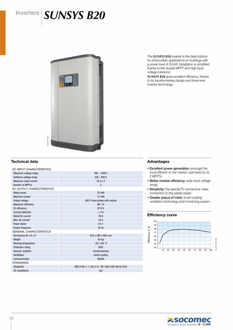
16
Inverters SUNSYS B20
Advantages
• Excellent power generation: amongst the most efficient on the market, optimised by its 2 MPPTs.
• Better module efficiency: wide input voltage range.
• Simplicity: the special PV connectors make connection to the panels easier.
• Greater peace of mind: smart-cooling ventilation technology and monitoring system.
The SUNSYS B20 inverter is the ideal solution for photovoltaic applications on buildings with a power level of 20 kW. Installation is simplified thanks to the double MPPT and high input voltage tolerance.
SUNSYS B20 gives excellent efficiency, thanks to its transformerless design and three-level inverter technology.
DC INPUT CHARACTERISTICS
Maximum voltage range 200 - 1000 V
Optimum voltage range 350 - 800 V
Maximum input current 32 A x 2
Number of MPPTs 2
AC OUTPUT CHARACTERISTICS
Rated power 20 kVA
Maximum power 21 kVA
Output voltage 400 V three phase with neutral
Maximum efficiency 98.1 %
EU efficiency 97.6 %
Current distortion < 3 %
Rated AC current 29 A
Max. AC current 32 A
Power factor 0.9-1
Output frequency 50 Hz
GENERAL CHARACTERISTICS
Dimensions W x D x H 610 x 290 x 965 mm
Weight 65 kg
Working temperature -20 / +60 °C
Protection rating IP65
Galvanic isolation transformerless
Ventilation smart-cooling
Communication RS485
STANDARDS
Standards VDE 0126-1-1, CEI 0-21, RD 1663, VDE-AR-N 4105
CE compliance yes
Technical data
SU
NS
Y 0
05 A
Efficiency curve
93
10 20 30 40 50 60 70 80 90 100
94
95
96
97
98
99
100
SU
NS
Y 0
28 A
GB

17
Inverters SUNSYS B30
Advantages
• Excellent power generation: amongst the most efficient on the market, optimised by its 2 MPPTs.
• Better module efficiency: wide input voltage range.
• Simplicity: the special PV connectors make connection to the panels easier.
• Greater peace of mind: smart-cooling ventilation technology and monitoring system.
The SUNSYS B30 inverter is the ideal solution for photovoltaic applications on buildings with a power of 30 kW. Installation is simplified thanks to the double MPPT and high input voltage tolerance.
SUNSYS B30 gives excellent efficiency, thanks to its transformerless design,and three-level inverter technology.
DC INPUT CHARACTERISTICS
Maximum voltage range 200 - 1000 V
Optimum voltage range 520 - 800 V
Maximum input current 32 A x 2
Number of MPPTs 2
AC OUTPUT CHARACTERISTICS
Rated power 30 kVA
Maximum power 33 kVA
Output voltage 400 V three phase with neutral
Maximum efficiency 98.1 %
EU efficiency 97.6 %
Current distortion < 3 %
Rated AC current 43 A
Max. AC current 46 A
Power factor 0.9-1
Output frequency 50 Hz
GENERAL CHARACTERISTICS
Dimensions W x D x H 610 x 290 x 965 mm
Weight 70 kg
Working temperature -20 / +60 °C
Protection rating IP65
Galvanic isolation transformerless
Ventilation smart-cooling
Communication RS485
STANDARDS
Standards VDE 0126-1-1, CEI 0-21, RD 1663, VDE-AR-N 4105
CE compliance yes
Technical data
SU
NS
Y 0
05 A
Efficiency curve
93
10 20 30 40 50 60 70 80 90 100
94
95
96
97
98
99
100
SU
NS
Y 0
28 A
GB

18

19
Inverters for solar parksPhotovoltaic parks generally occupy large ground areas and can accommodate sets of photovoltaic
panels covering thousands of square metres. These parks can produce high MWp crest factors.
High performance equipment is used to optimise the level of power injected into the grid. The power
produced is generally injected into the electricity grid at medium or high voltage via a transforming
substation.
Downstream of the panels, the SOCOMEC solution covers:
• DC protection and connection (see Equipment section),
• DC/AC conversion,
• AC protection and connection (see Equipment section),
• monitoring of generation system (see Monitoring section).
The inverter is a complex DC / AC conversion device and thus plays a crucial role in a PV system's
performance. As power generation in photovoltaic parks is subject to certain restrictions a number
of specific functions are required. In particular, solar inverters must be connected to a centralised
management system and their use and maintenance must be simplified.
When combined with the monitoring options and control panels of SUNSYS IFB strings,
SUNSYS solar park inverters are the optimum solution for maximising the output of the installation.
Solar parks
SUNSYS R01-R02-P02-P03 SUNSYS P03+T03

20
SU
NS
Y 0
17 A
Inverters SUNSYS R01 - R02
The SUNSYS R01 and SUNSYS R02 are the ideal inverters for roofs, with power ratings of 33 kW and 66 kW respectively. The SUNSYS R01 and SUNSYS R02 are highly efficient thanks to their modular architecture and DPC (Dynamic Power Control) function, which make it possible to increase power generation, especially at low solar radiation levels.
The maintenance and control of the system are simplified by the SUNSYS IFB options and the SUNGUARD monitoring software.
Advantages
DC INPUT CHARACTERISTICS R01 R02
Maximum voltage range 350 - 900 V
Optimum voltage range 450 - 850 V
Maximum input current 80 A 160 A
Number of MPPTs 1 1 to 2
AC OUTPUT CHARACTERISTICS
Rated power 33.3 kVA 66.7 kVA
Maximum power 36.6 kVA 73.4 kVA
Output voltage 400 V three phase with neutral
Maximum efficiency 97 %
EU efficiency 96 %
Current distortion < 3 %
Rated AC current 48 A 96 A
Max. AC current 53 A 106 A
Power factor 0.9-1
Output frequency 50 Hz
GENERAL CHARACTERISTICS
Dimensions W x D x H 600 x 795 x 1400 mm
Weight 330 kg 525 kg
Working temperature -5 / +55 °C
Protection rating IP20
Galvanic isolation LV transformer
Ventilation smart-cooling
Communication RS485
STANDARDS
Standards VDE 0126-1-1, CEI 0-21, RD 1663, VDE-AR-N 4105
CE compliance yes
Technical data
• Better PV system efficiency: SUNSYS R01 and SUNSYS R02 inverters maximise the global efficiency of the photovoltaic installation.
• Increased power generation: the DPC (Dynamic Power Control) function improves power generation, especially in low solar radiation conditions.
• Greater reliability: the operating conditions have been endorsed by independent certification bodies (dynamic efficiency, efficiency).
• Simplicity: maintenance, service provision and monitoring are simplified by the modular design of the SUNSYS R01, SUNSYS R02 and SUNSYS P03+T03 solutions.
Efficiency curve
86
10 20 30 40 50 60 70 80 90 100
88
90
92
94
96
98
100
SU
NS
Y 0
29 B
GB

21
SU
NS
Y 0
19 A
Inverters SUNSYS P03+T03
Advantages
• Optimum protection: IP20.
• Excellent power generation: amongst the most efficient on the market, optimised by the 3 MPPTs.
The SUNSYS P03+T03 is the ideal inverter for photovoltaic systems connected to a low voltage network. The SUNSYS P03+T03 maximises efficiency thanks to its multi-MPPT technology and modular architecture.
The SUNSYS IFB options and SUNGUARD monitoring system simplify the maintenance and control of the photovoltaic installation.
DC INPUT CHARACTERISTICS
Maximum voltage range 350 - 900 V
Optimum voltage range 450 - 850 V
Maximum input current 240 A
Number of MPPTs 1 to 3
AC OUTPUT CHARACTERISTICS
Rated power 100 kVA
Maximum power 110 kVA
Output voltage 400 V three phase with neutral
Maximum efficiency 97 %
EU efficiency 96 %
Current distortion < 3 %
Rated AC current 144 A
Max. AC current 160 A
Power factor 0.9-1
Output frequency 50 Hz
GENERAL CHARACTERISTICS
Dimensions W x D x H 1200 x 795 x 1400 mm
Weight 770 kg
Working temperature - 5 / + 55 °C
Protection rating IP20
Galvanic isolation LV transformer
Ventilation smart-cooling
Communication RS485
STANDARDS
Standards VDE 0126-1-1, CEI 0-21, RD 1663, VDE-AR-N 4105
CE compliance yes
Technical data
22
SU
NS
Y 0
17 A
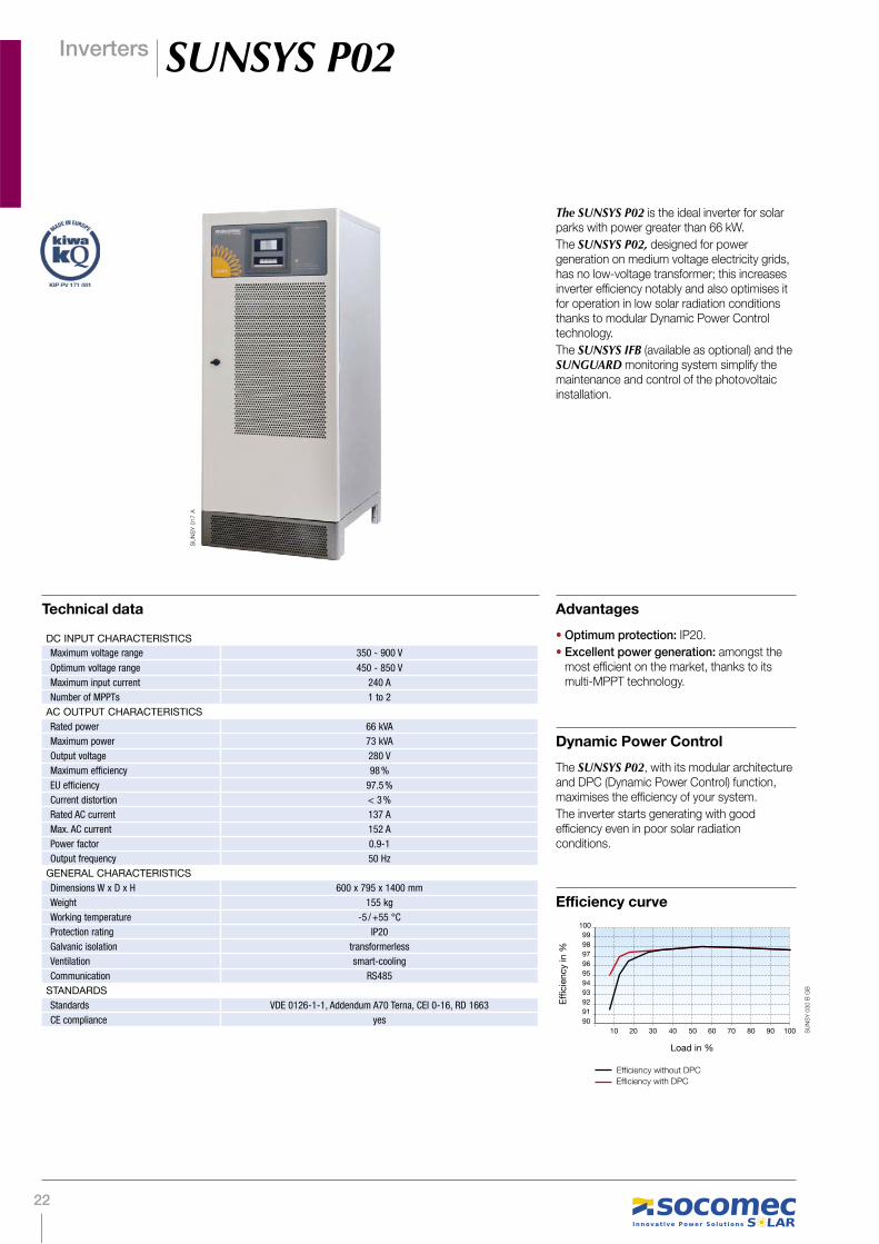
Inverters SUNSYS P02
Advantages
• Optimum protection: IP20.
• Excellent power generation: amongst the most efficient on the market, thanks to its multi-MPPT technology.
The SUNSYS P02 is the ideal inverter for solar parks with power greater than 66 kW.
The SUNSYS P02, designed for power generation on medium voltage electricity grids, has no low-voltage transformer; this increases inverter efficiency notably and also optimises it for operation in low solar radiation conditions thanks to modular Dynamic Power Control technology.
The SUNSYS IFB (available as optional) and the SUNGUARD monitoring system simplify the maintenance and control of the photovoltaic installation.
Dynamic Power Control
The SUNSYS P02, with its modular architecture and DPC (Dynamic Power Control) function, maximises the efficiency of your system.
The inverter starts generating with good efficiency even in poor solar radiation conditions.
DC INPUT CHARACTERISTICS
Maximum voltage range 350 - 900 V
Optimum voltage range 450 - 850 V
Maximum input current 240 A
Number of MPPTs 1 to 2
AC OUTPUT CHARACTERISTICS
Rated power 66 kVA
Maximum power 73 kVA
Output voltage 280 V
Maximum efficiency 98 %
EU efficiency 97.5 %
Current distortion < 3 %
Rated AC current 137 A
Max. AC current 152 A
Power factor 0.9-1
Output frequency 50 Hz
GENERAL CHARACTERISTICS
Dimensions W x D x H 600 x 795 x 1400 mm
Weight 155 kg
Working temperature -5 / +55 °C
Protection rating IP20
Galvanic isolation transformerless
Ventilation smart-cooling
Communication RS485
STANDARDS
Standards VDE 0126-1-1, Addendum A70 Terna, CEI 0-16, RD 1663
CE compliance yes
Technical data
90
10 20 30 40 50 60 70 80 90 100
91
92
93
94
95
96
97
99
98
100
Load in %
Efficiency curve
SU
NS
Y 0
30 B
GB

23
SU
NS
Y 0
17 A
Inverters SUNSYS P03
Advantages
• Optimum protection: IP20.
• Excellent power generation: amongst the most efficient on the market, thanks to its multi-MPPT technology.
The SUNSYS P03 is the ideal inverter for solar parks with power greater than 100 kW.
The SUNSYS P03, designed for power generation on medium voltage electricity grids, has no low-voltage transformer; this notably increases inverter efficiency and also optimises it for operation in low solar radiation conditions thanks to modular Dynamic Power Control technology.
The SUNSYS IFB (available as optional) and the SUNGUARD monitoring system simplify the maintenance and control of the photovoltaic installation.
Dynamic Power Control
The SUNSYS P03 inverter, with its modular architecture and DPC (Dynamic Power Control) function, maximises the efficiency of your system.
The inverter starts generating with good efficiency even in poor solar radiation conditions.
DC INPUT CHARACTERISTICS
Maximum voltage range 350 - 900 V
Optimum voltage range 450 - 850 V
Maximum input current 240 A
Number of MPPTs 1 to 3
AC OUTPUT CHARACTERISTICS
Rated power 100 kVA
Maximum power 110 kVA
Output voltage 280 V
Maximum efficiency 98 %
EU efficiency 97.5 %
Current distortion < 3 %
Rated AC current 206 A
Max. AC current 227 A
Power factor 0.9-1
Output frequency 50 Hz
GENERAL CHARACTERISTICS
Dimensions W x D x H 600 x 795 x 1400 mm
Weight 190 kg
Working temperature -5 / +55 °C
Protection rating IP20
Galvanic isolation transformerless
Ventilation smart-cooling
Communication RS485
STANDARDS
Standards VDE 0126-1-1, Appendix A70 Terna, CEI 0-16, RD 1663
CE compliance yes
Technical data
90
10 20 30 40 50 60 70 80 90 100
91
92
93
94
95
96
97
99
98
100
Load in %
Efficiency curve
SU
NS
Y 0
30 B
GB
24
Inverters SUNSYS ShelterS
ITE
577 A
AP
PLI 435 A
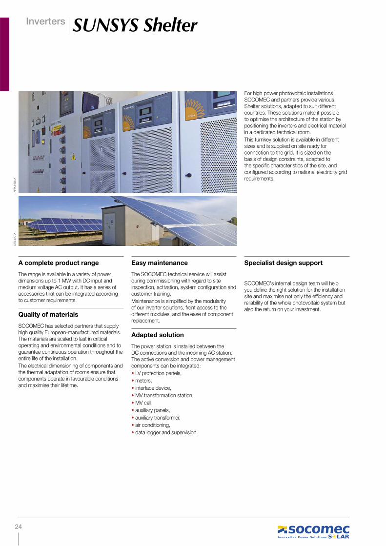
A complete product range
The range is available in a variety of power dimensions up to 1 MW with DC input and medium voltage AC output. It has a series of accessories that can be integrated according to customer requirements.
Quality of materials
SOCOMEC has selected partners that supply high quality European-manufactured materials. The materials are scaled to last in critical operating and environmental conditions and to guarantee continuous operation throughout the entire life of the installation.
The electrical dimensioning of components and the thermal adaptation of rooms ensure that components operate in favourable conditions and maximise their lifetime.
Easy maintenance
The SOCOMEC technical service will assist during commissioning with regard to site inspection, activation, system configuration and customer training.
Maintenance is simplified by the modularity of our inverter solutions, front access to the different modules, and the ease of component replacement.
Adapted solution
The power station is installed between the DC connections and the incoming AC station. The active conversion and power management components can be integrated:
• LV protection panels,
• meters,
• interface device,
• MV transformation station,
• MV cell,
• auxiliary panels,
• auxiliary transformer,
• air conditioning,
• data logger and supervision.
Specialist design support
SOCOMEC's internal design team will help you define the right solution for the installation site and maximise not only the efficiency and reliability of the whole photovoltaic system but also the return on your investment.
For high power photovoltaic installations SOCOMEC and partners provide various Shelter solutions, adapted to suit different countries. These solutions make it possible to optimise the architecture of the station by positioning the inverters and electrical material in a dedicated technical room.
This turnkey solution is available in different sizes and is supplied on site ready for connection to the grid. It is sized on the basis of design constraints, adapted to the specific characteristics of the site, and configured according to national electricity grid requirements.

25
FT
T
FT
FT
T T
Stringof panels
DC protection
AC protection
Transformer
Inverter
To MV panel
FT
T
FT
FT
T T
Inverters SUNSYS Shelter
Single line diagram
SH
ELT
001 A
GB

26

27
A photovoltaic system isn't just solar panels connected to an inverter. These 'vital organs' have to
be made complete with a set of protection devices in order to safeguard the generation system
against the unexpected.
SOCOMEC disconnection and protection solutions provide:
• safety during emergency intervention in the event of electric shock or fire, and during all
maintenance operations. SIRCO PV load-break switches ensure disconnection, switching off
in emergencies and switching off to allow firefighting access
• and the protection of assets, especially against solar panel inverse currents and overvoltages
generated by lightning. PV fuses and fuse basesprotect not only the panels against inverse
currents but also the PV generator strings against DC breakdown currents. SURGYS PV surge
protection devices protect the panels and inverters against overvoltages of atmospheric origin.
These switching and protection devices can either be housed in boxes or photovoltaic string
control cabinets (see Monitoring section), depending on the panel technology and the size of the
installation.
Equipment
SIRCO MC PV SIRCOVER PV SURGYS G51-PV
PV fuses Intelligent Field Box

28
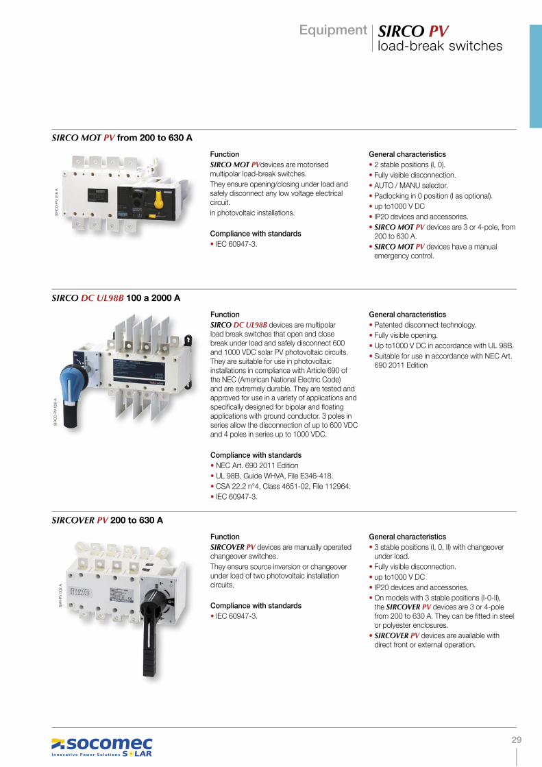
Equipment SIRCO PVload-break switches
The use of dedicated switches is imperative to ensure electrical disconnection during maintenance operations or for cutting off the power in emergencies when there are fire or electric shock hazards.
These components must be installed in accordance with the architecture at each operational level. When disconnecting a photovoltaic string or the DC side of an inverter, only SIRCO PV devices are capable of:
• isolating the high DC voltages that occur in this context
• disconnecting, under loads of thousands of volts and in total safety, the high DC currents that vary according to daily solar radiation.
Function
SIRCO MC PV devices are manually operated multipolar load break switches. They ensure opening/closing under load and safely disconnect any low voltage electrical circuit for PV systems.
Compliance with standards
• IEC 60947-1.
• IEC 60947-3.
• IEC 60364-7-712, NF C 15-100 andUTE C 15-712-1 Guideline.
• IEC 60364-4-410.
General characteristics
•Modular and modulable device.
• AC/DC device for complete isolation of the inverter thanks to the simultaneous cut-off of the DC current input and AC current output.
• Fully visible disconnection.
• Double break per phase with arc fragmentation system.
• DIN rail mounting, panel or modular panel with 45 mm front cut-out.
• 600 and 1000 VDC versions.
SIRCO MC PV 25 a 40 A
Function
SIRCO MV PV devices are manually operated multipolar load break switches.
They ensure opening/closing under load and safely disconnect any low voltage electrical circuit for PV systems.
Compliance with standards
• IEC 60947-3.
• EN 60947-3.
• VDE 0660-107 (1992).
• IEC 60364-4-410, IEC 60364-7-712,NF C 15-100 UTE C 15-712-1 Guideline.
General characteristics
• Modular device
• Fully visible opening.
• DIN rail mounting, panel or modular panel with 45 mm front cut-out.
• up to1000 V DC
SIRCO MC PV 63 to 160 A
Function
SIRCO PV devices are manually operated multipolar load break switches. They ensure opening/closing under load and safely disconnect any low voltage electrical circuit for PV systems.
Compliance with standards
• IEC 60947-3.
• EN 60947-3.
• VDE 0660-107 (1992).
• IEC 60364-4-410, IEC 60364-7-712,NF C 15-100 UTE C 15-712-1 Guideline.
General characteristics
• Patented disconnect technology.
• Fully visible opening.
• DIN rail or panel mounting.
• Up to 1000 V DC
SIRCO PV 100 to 1250 A
SIR
CO
-MC
002 A
1 C
AT
SIR
CM
-PV
010 A
SIR
CO
-PV
005 A
29
Equipment SIRCO PVload-break switches
Function
SIRCO MOT PVdevices are motorised multipolar load-break switches.
They ensure opening/closing under load and safely disconnect any low voltage electrical circuit.
in photovoltaic installations.
Compliance with standards
• IEC 60947-3.
General characteristics
• 2 stable positions (I, 0).
• Fully visible disconnection.
• AUTO / MANU selector.
• Padlocking in 0 position (I as optional).
• up to1000 V DC
• IP20 devices and accessories.
• SIRCO MOT PV devices are 3 or 4-pole, from 200 to 630 A.
• SIRCO MOT PV devices have a manual emergency control.
SIRCO MOT PV from 200 to 630 A
Function
SIRCO DC UL98B devices are multipolar load break switches that open and close break under load and safely disconnect 600 and 1000 VDC solar PV photovoltaic circuits. They are suitable for use in photovoltaic installations in compliance with Article 690 of the NEC (American National Electric Code) and are extremely durable. They are tested and approved for use in a variety of applications and specifically designed for bipolar and floating applications with ground conductor. 3 poles in series allow the disconnection of up to 600 VDC and 4 poles in series up to 1000 VDC.
Compliance with standards
• NEC Art. 690 2011 Edition
• UL 98B, Guide WHVA, File E346-418.
• CSA 22.2 n°4, Class 4651-02, File 112964.
• IEC 60947-3.
General characteristics
• Patented disconnect technology.
• Fully visible opening.
• Up to1000 V DC in accordance with UL 98B.
• Suitable for use in accordance with NEC Art. 690 2011 Edition
SIRCO DC UL98B 100 a 2000 A
Function
SIRCOVER PV devices are manually operated changeover switches.
They ensure source inversion or changeover under load of two photovoltaic installation circuits.
Compliance with standards
• IEC 60947-3.
General characteristics
• 3 stable positions (I, 0, II) with changeover under load.
• Fully visible disconnection.
• up to1000 V DC
• IP20 devices and accessories.
• On models with 3 stable positions (I-0-II), the SIRCOVER PV devices are 3 or 4-pole from 200 to 630 A. They can be fitted in steel or polyester enclosures.
• SIRCOVER PV devices are available with direct front or external operation.
SIRCOVER PV 200 to 630 A
SIR
CO
-PV
016 A
SV
R-P
V 0
02 A
SIR
CO
-PV
026 A

30
Equipment PV Fuses, fuse bases
Function
RM PV are disconnectors with unipolar or bipolar modular fuses for PV 10 X 38 cylindrical fuses. They ensure safe disconnection and protection against overcurrents in all PV electrical circuits on the DC current side.
RM: fuse bases without signalling for fuses without striker.
Compliance with standards
• IEC 60947-3.
• IEC 60269-2-1.
• IEC 60269-1.
• IEC 60269-2.
• NF EN 60269-1.
• NF C 63-210.
• NF C 63211.
• VDE 0636-10.
• DIN 43620.
General characteristics
• Rated voltage of 1000 V DC.
• multipolar and simultaneous disconnection.
• High dielectric strength.
• Modular DIN 45 mm cut-out.
• Self-extinguishing thermoplastic material.
• High capacity connection.
RM PV
Function
SOCOMEC PV fuses protect the system against the inverse overcurrents that can occur in photovoltaic installations. They are available in both cylindrical and blade form.
Compliance with standards
• IEC 60269-6.
• IEC 60269-1.
• IEC 60269-2.
• NF EN 60269-1.
• VDE 0636-10.
PERFORMANCE
• Breaking capacity up to 1000 V DC
• Extensive working range, suitable for the small over-currents typical of PV installations.
• Simple, reliable selectivity.
Reliability
• Total protection over time guaranteed by the simplicity of construction and operation (Joule effect).
Safety
• The energy released during a short circuit is contained within the sealed fuse cartridge.
PVFuses - gPV Fuses
Function
SOCOMEC fuse bases are fixed, unipolar or multipolar supports for knife edge fuses.
Compliance with standards
• IEC 60269.
• NF EN 60269-1.
• VDE 0636-10.
• DIN 43620.
General characteristics
• High dielectric strength.
PV bases
RM
056 A
FU
SIB
-PV
_016_A
_1_C
AT
SO
CLE
-PV
002 A
1 C
AT
FU
SIB
-PV
_016_A
_1_C
AT

31
Equipment SURGYS PV surge arrestors
Photovoltaic panels and inverters account for a sizeable proportion of total investment.
Depending on its architecture, the surface of a photovoltaic field can act as a large antenna and can easily capture potentially damaging overvoltages in a storm.
The use of SURGYS surge arresters, specially designed for PV installations, can reduce this risk considerably. The specific design of these surge protective devices makes them fully capable of controlling the discharge of the transient current after a strike and disconnecting the DC currents, even at end-of-life.
The specific PV surge protective devices protect the panels and inverters against overvoltages of atmospheric origin.
SURGYS G51-PV
Function
The SURGYS G51-PV surge protective device is designed to protect your photovoltaic installations. It acts against the overvoltages produced by discharges.
It complies with the UTE 61-740-51 test guidelines and the UTE 15-712 installation guidelines of July 2010.
Compliance with standards
• NF EN 61643-11 Class 2 tests.
• IEC 61643-1 Class 2.
• UTE C 61-740-51.
• UTE C 15-712-1 (2010).
General characteristics
• Type 2 Surge Protective Device.
• Available with protection from 500 V DC to 1000 V DC
• Max. discharge current 40 kA.
• Monobloc base.
• Common mode / differential mode protection.
• Extractable remote signalling contact (depending on model)
• End of service life indicator.
• Plug-in module.SG
YS
076 A
SURGYS D40
Function
The SURGYS D40 surge protective device is designed to ensure the protection of LV distribution circuits and equipment against transient overvoltages.
It acts against the overvoltages produced by industrial processes or lightning.
Compliance with standards
• NF EN 61643-11 Class 2 tests.
• IEC 61643-1 Class 2.
General characteristics
• Type 2 Surge Protective Device.
• Max. discharge current 40 kA.
• Common mode / differential mode protection.
• Monobloc base.
• Extractable remote signalling contact.
• End of service life indicator.
• Plug-in module.
• Differential mode versions (only TT and TN conditions.
• Fuse holder recommended: RM.SG
YS
069 A
1 C
AT
32
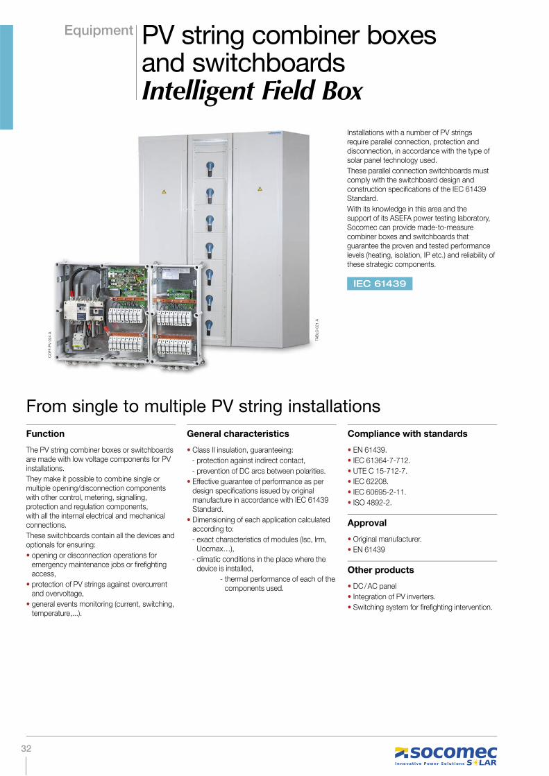
Equipment PV string combiner boxes and switchboardsIntelligent Field Box
Installations with a number of PV strings require parallel connection, protection and disconnection, in accordance with the type of solar panel technology used.
These parallel connection switchboards must comply with the switchboard design and construction specifications of the IEC 61439 Standard.
With its knowledge in this area and the support of its ASEFA power testing laboratory, Socomec can provide made-to-measure combiner boxes and switchboards that guarantee the proven and tested performance levels (heating, isolation, IP etc.) and reliability of these strategic components.
Function
The PV string combiner boxes or switchboards are made with low voltage components for PV installations.
They make it possible to combine single or multiple opening/disconnection components with other control, metering, signalling, protection and regulation components, with all the internal electrical and mechanical connections.
These switchboards contain all the devices and optionals for ensuring:
• opening or disconnection operations for emergency maintenance jobs or firefighting access,
• protection of PV strings against overcurrent and overvoltage,
• general events monitoring (current, switching, temperature,...).
General characteristics
• Class II insulation, guaranteeing:
- protection against indirect contact,
- prevention of DC arcs between polarities.
• Effective guarantee of performance as per design specifications issued by original manufacture in accordance with IEC 61439 Standard.
• Dimensioning of each application calculated according to:
- exact characteristics of modules (Isc, Irm, Uocmax…),
- climatic conditions in the place where the device is installed,
- thermal performance of each of the components used.
Compliance with standards
• EN 61439.
• IEC 61364-7-712.
• UTE C 15-712-7.
• IEC 62208.
• IEC 60695-2-11.
• ISO 4892-2.
Approval
• Original manufacturer.
• EN 61439
Other products
• DC / AC panel
• Integration of PV inverters.
• Switching system for firefighting intervention.
From single to multiple PV string installations
CO
FF-P
V 0
24 A
TAB
LO
021 A
IEC 61439

33
The objective of a Class II device is to protect users from indirect contact with live parts. This also applies to the polarities of PV modules, as electric arcs in PV installations can be particularly destructive and protection against them is essential. Standard requirements on this put particular emphasis on the (Class II) physical separation of the + and – poles (unipolar PV cable). These requirements must be applied to the enclosures and switchboards where all strings and sets of strings are connected.
A photovoltaic installation has the characteristic of placing all the components of the enclosure under continuous stress, whereas in most other applications this stress is occasional, and this is in addition to the stresses of the ambient temperature and the direct exposure to the sun's rays. Theoretical simulation is not enough to guarantee the perfect management of heat increases or the unexpected tripping of overcurrent protection devices. Only laboratory testing in accordance with IEC 61 439 Standard procedures can give the right indications for guaranteeing the effective operation of the system.
Our combiner switchboards have been designed and tested as specified in the standards and guarantee compliance with all the requirements and specifications of these installations.
We can provide you with exactly the right solution for your installation, from a simple residential box to a multi-inverter enclosure with monitoring.
Range of PV string combiner switchboards
What you need to know
Equipment PV string combiner boxesand switchboardsIntelligent Field Box

34

35
Large-size photovoltaic installations are equipped with infrastructure to allow on-site and remote
monitoring.
SOCOMEC provides a complete solution for the optimum control of the installation:
• the DIRIS system (multifunction measurement and network analyser units) makes it possible to
view, at any point on the network, the electrical parameters required for managing and controlling
the quality of the power generated. These units communicate with the supervisor via an RS485
connection,
• the photovoltaic string combiner boxes and cabinets guarantee that the various generators
in the system are grouped together in protected enclosures. They contain the circuit breaker,
protection devices, and measurement devices. We can provide you with exactly the right solution
for your installation configuration, from a simple residential box to a multi-inverter enclosure with
monitoring.
• the SUNGUARD software guarantees the complete monitoring of the photovoltaic installation,
using a PC with browser and Internet connection. SUNGUARD, by simplifying the troubleshooting
procedure, reduces system downtime considerably. It also allows you to check that the power
generation meets financial targets for the photovoltaic installation, and note the contribution in
terms of renewable energy and environmental benefits.
Monitoring
DIRIS A40 SUNGUARD

36
Monitoring Monitoring withthe DIRIS system
Complete monitoring is indispensable not only because it provides specific data on power generation, but also because it compiles historical statistics on events and guarantees the efficient overall operation of the system.
Depending on the size of the installation, the DIRIS system can provide a range of solutions for metering, managing and analysing the generation and quality of the power.
• Multi-function measurement and advanced metering.
• individual harmonics to 63rd order.
• RS485 communication (Jbus / Modbus and Profibus-DP) and Ethernet (Modbus TCP and Jbus / Modbus over TCP)
• Alert management.
•Power forecasting.
• 96 x 96 mm container.
DIRIS A40
DIR
IS 7
42 A
37
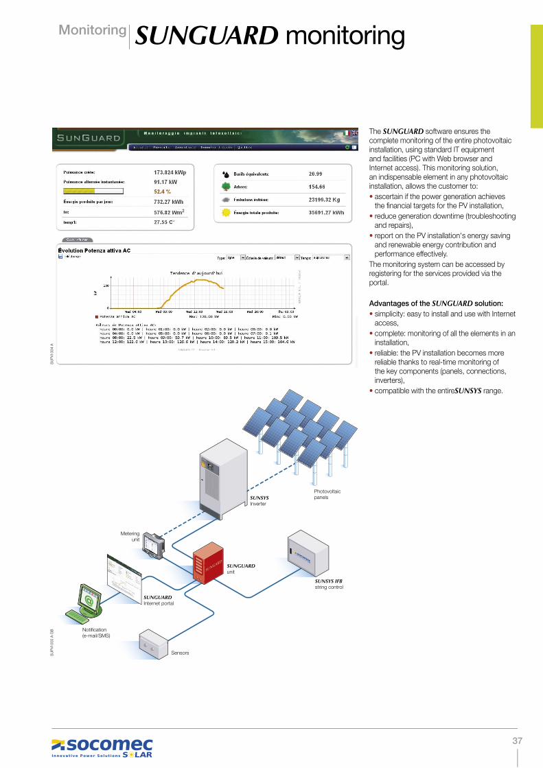
Monitoring SUNGUARD monitoring
The SUNGUARD software ensures the complete monitoring of the entire photovoltaic installation, using standard IT equipment and facilities (PC with Web browser and Internet access). This monitoring solution, an indispensable element in any photovoltaic installation, allows the customer to:
• ascertain if the power generation achieves the financial targets for the PV installation,
• reduce generation downtime (troubleshooting and repairs),
• report on the PV installation's energy saving and renewable energy contribution and performance effectively.
The monitoring system can be accessed by registering for the services provided via the portal.
Advantages of the SUNGUARD solution:
• simplicity: easy to install and use with Internet access,
• complete: monitoring of all the elements in an installation,
• reliable: the PV installation becomes more reliable thanks to real-time monitoring of the key components (panels, connections, inverters),
• compatible with the entireSUNSYS range.
DIRIS D600
SUNGUARDunit
Meteringunit
SUNGUARDInternet portal
(e-mail/SMS)
Sensors
SUNSYSInverter
SUNSYS IFB
panels
SUNSYS
@
SU
PV
I 004 A
SU
PV
I 005 A
GB

38
Technology Inverter technology
With over 40 years experience in the design and manufacture of uninterruptible power supply systems, SOCOMEC has always been at the cutting edge of technology in electrical power conversion.
SUNSYS inverters, made by SOCOMEC SOLAR, have benefited from the technological progress resulting from this knowledge. These innovative technologies increase the efficiency and lifetime of your installations.
Maximum power point tracking
SOCOMEC inverters use a maximum power point (MPP) tracking algorithm that ensures the maximum utilisation of the power supplied by the solar panels.
Our experience in the field has shown us that the MPPT can vary sharply in relation to the temperature and intensity of the sun's rays. That's why we've developed an algorithm that solves this problem and gives very good dynamic behaviour results.
This dynamic efficiency is certified by the Fraunhofer-Instituts für Solare Energiesysteme. These results make SOCOMEC SOLAR inverters the market benchmark.
Smart-Cooling technology
Cooling is a crucial element in the efficient operation and lifetime extension of an inverter. That's why we've developed a smart cooling system.
The fans are controlled and operated on demand, taking account of the input load and temperature, in order to optimise heat dissipation.
3-level inverter topology
+ 400 V
- 400 V
2-level bridge inverter
0 V
- 400 V
3-level bridge inverter
+ 400 V
SUNSYS inverters are made with the use of 3-level inverter bridge topology, based on SOCOMEC's considerable experience in this field (10 years of research on UPS Green Power products).
This technology, an innovation in electrical power conversion applications, reduces the voltage between the IGBT terminals (power switches) by half.
The switching losses are thus reduced significantly.
This optimisation of the inverter bridge means thatSUNSYS inverters can achieve a conversion efficiency of over 98%.
SU
NS
Y 0
23 A
GB

39
Technology Inverter technology
Dynamic Power Control
Given the average annual solar radiation in Europe, photovoltaic stations have to work most of the time in reduced luminosity conditions. The efficiency of the inverter is thus essential, despite the poor meteorological conditions.
The SUNSYS inverter, with its modular architecture and DPC (Dynamic Power Control) function, maximises the efficiency of your system.
The inverter starts generating efficiently even when the solar radiation is very low.
• The best efficiency
The DPC optimises the efficiency of your installation in a particular way for partial loads. The inverter starts generating electricity from a low solar radiation level. The P03 inverter gives 96% efficiency with a load of just 5 %.
• Longer lifetime
Thanks to the DPC, only the modules actually needed for power generation operate. The power models are also operated cyclically to share the load time. The operating time of a module is thus optimised, and this lengthens the useful lifetime of the inverter.
• Better availability
If one of the inverter power modules stops (due to a breakdown), the system will reconfigure automatically in order to get the best use out of the remaining modules and continue supplying the maximum possible amount of power.
% load
WITHOUT
% load
% load
Percentage load
WITH
% load
% load
% load
Percentage load
0% 20%
40%
60%
80%
100%
Standard inverterDynamic Power Control
84%
86%
88%
90%
92%
94%
96%
98%
Their modularity allows them to maximise overall efficiency by using only the power modules that it needs. In poor solar radiation conditions, less modules are used, working with greater loads and therefore with greater efficiency.
Comparison with/without DPC
SU
NS
Y 0
22 A
GB
SU
NS
Y 0
20 A
GB
SU
NS
Y 0
21 A
GB

40
Summary Summary ofphotovoltaic systems
Fixed for residential use
Buildings
1 Disconnecting and switching under load upstream/downstream of inverter
2 Surge protective device against overvoltages of atmospheric origin
3 Solar inverter for conversion to alternating current to be delivered to the grid
4 Consumption and generation metering
1 3
14
1 Disconnecting and switching under load upstream/downstream of inverter
2 Protection against DC side inverse currentsand AC side short circuits
3 Protection of inverters against overvoltages of atmospheric origin
4 Checking of insulation to prevent system degradation
5 Parallel arrangement of disconnection and protection functions on electrical switchboards
6 Conversion by means of centrally managed solar inverters to ensure the optimum effi ciency of the installation
7 Metering, management, analysis and monitoring of generating system
2
1
6
5
2 3 4
7
SY
DIV
047 A
SY
DIV
047 A

41
Summary Summary of photovoltaic systems
1 Disconnecting and switching under load upstream/downstream of inverter
2 Protection against DC side inverse currents and AC side short circuits
3 Protection of inverters against overvoltages of atmospheric origin
4 Checking of insulation to prevent system degradation
5 Connection in parallel, disconnection and protection of strings
6 Conversion by means of centrally managed solar inverters to ensure the optimum effi ciency of the installation
7 Metering, management, analysis and monitoring of generating system
1 Disconnection and switching under load of PV string
2 Protection of PV strings against inverse currents
3 Protection of PV strings against overvoltages of atmospheric origin
4 Metering and monitoring of strings
Solar parks
12
3
4
6
57
12
34
SY
DIV
047 A

42
Some references
Taglio di Po - Italy
Adria - Italy
Ferrara - Italy
Berlin - Germany
Strasbourg - France
Power: 300 kW
Panel technology: Polycrystalline
Power: 240 kW
Panel technology: Polycrystalline
Power: 1.9 MW
Panel technology: Polycrystalline
Power: 418 kW
Panel technology: CIS
Power: 900 kW
Panel technology: Monocrystalline
SIT
E 5
83 A
SIT
E 5
84 A
AP
PLI 441 A
SIT
E 5
78 A
SIT
E 5
80 A
AP
PLI 436 A
AP
PLI 440 A
AP
PLI 437 A
SIT
E 5
79 A
AP
PLI 438A

43
Notes

44
Notes

45
Notes

46
Notes

47
Notes

48
Notes

Production: SOCOMECGraphics: SOCOMECPhotography: Martin Bernhart and SOCOMECPrinting: SOCOMEC
To help safeguard the environment, this document has been printed on PEFC (Program for the Endorsement of Forest Certifi cation) paper.

www.socomec.com
VALID FOR FRANCE VALID FOR ITALY
ISO 9001:2008FM 28237
ISO14001:2004EMS 553476
Réf. D
OC
1140
23 -
09/1
2 -
Photo
: M
art
in B
ern
hart
- R
éalis
atio
n: S
OC
OM
EC
Serv
ice C
om
munic
atio
n -
Imp
rimeur
- To
help
safe
guard
the e
nvi
ronm
ent,
this
do
cum
ent
has
been p
rinte
d o
n P
EFC
(P
rog
ram
fo
r th
e E
nd
ors
em
ent
of Fo
rest
Cert
ificatio
n) p
ap
er
YOUR DISTRIBUTOR
Non c
ontrac
tual
docum
ent. ©
2012, S
ocom
ec S
A. A
ll rig
hts
rese
rved.
HEAD OFFICE
SOCOMEC GROUP
S.A. SOCOMEC capital 10 951 300 € R.C.S. Strasbourg B 548 500 149B.P. 60010 - 1, rue de Westhouse - F-67235 Benfeld CedexSOCOMEC UPS Strasbourg
11, route de Strasbourg - B.P. 10050 - F-67235 Huttenheim Cedex- FRANCETel. +33 (0)3 88 57 45 45 - Fax +33 (0)3 88 74 07 [email protected] UPS Isola Vicentina
Via Sila, 1/3 - I - 36033 Isola Vicentina (VI) - ITALYTel. +39 0444 598611 - Fax +39 0444 [email protected]
SALES AND MARKETING MANAGEMENT.
SOCOMEC SOLAR
Via Sila, 1/3I - 36033 Isola Vicentina (VI) - ITALYTel. +39 0444 598611 - Fax +39 0444 [email protected]


![Lenovo H50 SeriesHardware Maintenance Manual · Lenovo H50 Series Hardware Maintenance Manual Machine Types: 90C1 [H50-00]; 90BH [H50-05]; 90B6 [H50-50 ES]; 90B7 [H50-50 Non-ES];](https://img.pdfslide.us/doc/110x75/5f059c037e708231d413cfc0/lenovo-h50-serieshardware-maintenance-manual-lenovo-h50-series-hardware-maintenance.jpg)