Embed Size (px)
Citation preview

DOCUMENT TYPE
TECHNICAL SPECIFICATIONNO.
I-ET-3010.00-1500-960-PPC-011CLIENT OR USER E&P-SSE/E&P-SERV/UN-BC/UN-RIO/UN-ES SHEET 1 OF 27
JOB OR PROJECT GENERAL USE, AS APPLICABLE REV F
AREA OR UNIT SCALE
CENPES TITLE
GENERAL BEND STIFFENER REQUIREMENTS BROFFICE.ORG WRITER\I-ET-3010.00-1500-960-PPC-011 REV.F.ODT
INDEX OF REVISIONS
REV DESCRIPTION AND / OR REVISED SHEETS
0 ORIGINAL ISSUE
A GENERAL REVISION
B AMENDS TO INCORPORATE SUGGESTIONS FROM MANUFACTURERS AND CLARIFY SOME ITEMS
C RESECTIONING AND AMENDS ON CORROSION RESISTANT MATERIALS, TEST PROCEDURES.
D INCLUSION OF FIXED BEND STIFFENER (FBS) AND AMENDS TO INCORPORATE SUGGESTIONS FROM E&P TEAM.
E CHANGES IN MINIMUM BEND STIFFENER REQUIREMENTS, DESIGN ACCEPTANCE CRITERIA, BOLT MATERIAL AND
DYNAMIC TEST PROCEDURE.F REFERENCES TO NEW SPEC THAT REPLACES N-2409; UPDATE OF REFERENCE TO STANDARDS IN SECTION 12;
CORRECTION OF ALLOWABLE CRA HARDNESS IN SECTION 8.3, INCLUSION OF SECTION 10.1 MINIMUMREQUIREMENTS FOR SURFACE FINISHING, INCLUDING ROUGHNESS AND FLAW CRITERIA, INCLUSION OFSECTION 10.2 BOLT TORQUE AND PRE-LOAD PRECISION AND RENUMBERING THROUGHOUT SECTION 10.TREATMENT OF HOT SPOTS IN STRUCTURAL ANALYSIS, REQUIREMENTS FOR SURFACE PROTECTION DURINGHANDLING, CHANGES IN TABLE OF MAXIMUM ALLOWABLE STRAIN, INCLUSION OF RESULT REPORTINGREQUIREMENTS, REQUIREMENT OF NCR/NCTR AS DOCUMENT DELIVERED TO CLIENT.
REV 0 REV A REV B REV C REV D REV E REV F REV G REV H
DATE JUL/2004 AUG/2004 MAY/2005 JAN/2007 DEZ/2007 FEV/2009 MAI2014
DESIGN CENPES CENPES CENPES CENPES CENPES CENPES CENPES
EXECUTION VOLNEY,ANDERSON
VOLNEY,ANDERSON
VOLNEY,ANDERSON
ANDERSON ANDERSON ANDERSON ANDERSON
CHECK CAOLEMOS CAOLEMOS CAOLEMOS LLLF BUSCACIO CAOLEMOS BRUNOPINHO
APPROVAL CEZARPAULO CEZARPAULO CEZARPAULO LOUISE LOUISE LOUISE ARTHURSAAD
REV I REV J REV K REV L REV M REV N REV O REV P REV Q
DATE
DESIGN
EXECUTION
CHECK
APPROVALTHE DATA, OR PART THEREOF, ARE PETROBRAS PROPERTY AND THUS MUST NOT BE USED IN ANY WAY WITHOUT PERMISSION
PETROBRAS STANDARD FORM BY N – 381 REV E

DOCUMENT TYPE
TECHNICAL SPECIFICATIONNO.
I-ET-3010.00-1500-960-PPC-011REV
FAREA OR UNIT SHEET 2 OF 27
TITLE
GENERAL BEND STIFFENER REQUIREMENTS
1.0 PURPOSE
This Technical Specification (ET) aims to establish minimum requirements for design, material selection,manufacture and qualification of bend stiffeners used to prevent overbending and fatigue of flexible pipesand umbilical cables.
2.0 SCOPE
Requirements, specifications and recommended practices cited hereinafter are applicable for all bendstiffeners for flexible pipes and umbilical cables used offshore Brazil and regulate the minimum requirementswhich shall be met by manufacturer and Independent Verification Agent (IVA), as defined below. Additionalrules and recommended practices may be given in the following regulations and ETs:
• I-ET-3000.00-6500-291-PAZ-038 Flexible Pipe (replacement of Standard N-2409) [1].
• I-ET-3500.00-6500-291-PAZ-001 [2]: for nonstandardized prototype qualification tests.
• Applicable bellmouth/i-tubing interface specification for sliding, FBS and DCDE bend stiffeners, aswell as any other applicable documentation attached to the particular flexible I-RM, including all ETsin format I-ET-3010.xx-1300-279-PPC-0yy [3].
• I-ET-3010.00.1500-960-PPC-012 [4] : for DCDE bend stiffener conceptual design.
• I-ET-3500.00.6500-291-PAZ-026 [5]: for new product or supplier management.
• ET-3500.00-1516-940-PDS-011 [6] (in Portuguese): for cathodic protection of subsea equipment.
3.0 ABBREVIATIONS AND DEFINITIONS
Bellmouth: flared structural component connected to the downmost edge of I-tube, in which sliding, FBS orDCDE bend stiffener is fit.
Cap: most external metallic portion of bend stiffener, as shown in figure 3.1.
Centralizer: cylindrical part attached to the flexible pipe and fit in the bellmouth as show in figure 3.1.
CRA: corrosion resistant alloy.
DCDE: sliding dual bend stiffener with dual conical body, as shown in figure 3.1.
End-fitting bend stiffener: bend stiffener to be fixed onto a rigid support generally by bolting.
FAT: factory acceptance test.
FBS: bend stiffener fixed to the flexible pipe (or umbilical) with a metallic cylindrical centralizer.
FEA: finite element analysis.
FMECA: failure modes and engineering criticality analysis.
Flared liner: polymeric sleeve (and its end fitting) which internally coats the ending sleeve, avoiding contactbetween pipe’s external sheath and metallic parts.
Flexible manufacturer: the manufacturer or supplier of the flexible pipe or umbilical.
FPU: floating production unit.
FSHR: free standing hybrid riser.
Hot spot: localized area at which stresses substantially exceed neighboring stress values.
Insert: bend stiffener’s internal reinforcing structure, in general made of steel, which is bonded to or undercontact with the surrounding polymeric body.
IRC, Independent Review Certificate: review by which an IVA states that the art, design methodology, designcalculations, and manufacturing processes for specific product are in conformity with the applicable productspecifications and references.
THE DATA, OR PART THEREOF, ARE PETROBRAS PROPERTY AND THUS MUST NOT BE USED IN ANY WAY WITHOUT PERMISSION
PETROBRAS STANDARD FORM BY N – 381 REV E

DOCUMENT TYPE
TECHNICAL SPECIFICATIONNO.
I-ET-3010.00-1500-960-PPC-011REV
FAREA OR UNIT SHEET 3 OF 27
TITLE
GENERAL BEND STIFFENER REQUIREMENTS
I-RM, International Material Request: documentation issued by PETROBRAS to define the specificrequirements of products or equipment to be supplied.
IVA: Independent Verification Agent.
LSV: lay service vessel.
May: on course of action.
MBR: minimum bending radius.
Minimum bend stiffener: small bend stiffener, usually for intermediate connections and static service.
MQP: manufacturing quality plan.
NCR: non-conformity report.
NCTR: non-conformity treatment report.
NC, Non-conformity: any deviation from documented procedures, break of allowable ranges of controlledparameters, unexpected hazard, defect or damage, disapproval during qualification or FAT, lack of criteria orprocedure which could cause a product bad performance, etc.
NDE: non-destructive examination.
NDT: non-destructive test.
Pipe supplier: the manufacturer or supplier of the flexible pipe or umbilical cable.
Premise: basis, stated or assumed, on which product conception and engineering are performed and whichis consistently followed during design, manufacture, installation and operation.
Prototype: as per [1].
Purchaser: PETROBRAS asset, affiliate, partner or sub-contractor in charge of procurement.
Reinforcement structure: metallic component, usually toroid of a circular cross-section used to reinforce thepolymeric body at its largest section.
Shall: mandatory requirement.
Should: recommended practice.
Sliding bend stiffener: bend stiffener which can slide along the pipe as the dogs which hold it on place areunlocked, usually for installation in bellmouths.
Steelwork: all metallic parts of the bend stiffener, especially before the polymer moulding process.
Studbolts: metallic bolts which link the reinforcement structure to the flange.
Supplier: the company which supplies the bend stiffener, usually the flexible pipe supplier.
Tip: short cylindrical part at the downmost end of polymeric body.
Top structure: upmost metallic part (in Portuguese called trombeta) of a sliding bend stiffener, which casesthe pipe and sometimes has a flared shape.
Type approval: certificate through which IVA states the range of applications, limits and constraints of designmethods, criteria, material data and fabrication processes related to a family of products, based onevidences, provided by the manufacturer, confirming that they are in accordance with the requirements for asafety use and with the rules herein stated.
UV: ultraviolet.
VIV: vortex induced vibrations.
THE DATA, OR PART THEREOF, ARE PETROBRAS PROPERTY AND THUS MUST NOT BE USED IN ANY WAY WITHOUT PERMISSION
PETROBRAS STANDARD FORM BY N – 381 REV E

DOCUMENT TYPE
TECHNICAL SPECIFICATIONNO.
I-ET-3010.00-1500-960-PPC-011REV
FAREA OR UNIT SHEET 4 OF 27
TITLE
GENERAL BEND STIFFENER REQUIREMENTS
Figure 3.1. From top to bottom: sliding, end-fitting, minimum and DCDE and FBS bend stiffener.
THE DATA, OR PART THEREOF, ARE PETROBRAS PROPERTY AND THUS MUST NOT BE USED IN ANY WAY WITHOUT PERMISSION
PETROBRAS STANDARD FORM BY N – 381 REV E
CONICAL BODYCAP
TIP
TRANSITION
INSERT
STUDBOLT
STRUCTURAL RIBS
FLANGE
REINFORCED STRUCTURE
FLARED LINER
TOP STRUCTURE
END-FITTING FLANGE
END-FITTING
LOWER CONICAL BODYUPPER CONICAL BODY
DOCUMENT TYPE
TECHNICAL SPECIFICATIONNO.
I-ET-3010.00-1500-960-PPC-011REV
FAREA OR UNIT SHEET 5 OF 27
TITLE
GENERAL BEND STIFFENER REQUIREMENTS
4.0 RESPONSIBILITIES
Purchaser: (a) provide all applicable functional requirements for the supply, as per [1].
(b) review and approve any criterion and qualification not previously defined inthe specifications, based on the product concept and design philosophy,proposed by manufacturer.
Manufacturer: (a) supply information required for structural analysis or verification.
(b) supply a product which complies with functional and design requirementsmentioned herein, but not limited to them, considering also any otherrelevant Standard and its own experience, in order to assure a safety use allalong its service life. Manufacturer shall comply with ISO-9000/9001/9004/19011 [7,8,9,10] . Either flexible manufacturer or bend stiffenermanufacturer shall provide an IVA review and certification, as well as thevalidation of design methodologies as per sections 5.2.2 or 5.2.6 of [1], asapplicable.
IVA: as given in [1].
5.0 QUALIFICATION ENVELOP
The manufacturer and IVA shall define the envelop of design and manufacturing parameters within which itsmaterials, design methodologies and manufacturing practices are validated and certified as per item 5.2.2 in[1]. Unless properly justified, every new product is deemed to be a prototype. The justification for anon-prototype product shall include:
(a) envelope of applications for which design and manufacturing methods are validated and certified byIVA.
(b) results on similarity analyses, comparing the previously-qualified product’s parameters andperformance with the characteristics of products.
(c) evidences that the product will not meet failure mechanisms beyond the capabilities of the designmethodology to predict them.
5.1 SIMPLIFICATION OF QUALIFICATION PROGRAM FOR SMALL DESIGN CHANGES
Even if a product is deemed to be a prototype, the scope of its qualification programme can be simplifiedprovided that following conditions apply:
(a) manufacturer, purchaser, supplier and IVA agree to do such simplification and on its extent.
(b) the manufacturer or supplier has successful track records as a PETROBRAS supplier, as well as ISO9001/9004 certification and certification according to section 5.2.2 of [1], applicable to the relatedproduct.
(c) the actual utilization factors for the new product shall be at least the ones of the previously qualifiedproduct, for the applicable failure mechanisms.
6.0 GENERAL FUNCTIONAL REQUIREMENTS
Bend stiffeners under scope of this ET shall comply with all following functional requirements:
(a) the product shall limit the curvature in the flexible pipe or umbilical to the reciprocal of its dynamic MBRfor any accidental or extreme environmental condition predicted as per section 8 of API RP 17B[11] andsection 5.3.5 of [1], considering the most adverse combinations of temperature, material degradation,creep and other factors present in actual stiffening system.
THE DATA, OR PART THEREOF, ARE PETROBRAS PROPERTY AND THUS MUST NOT BE USED IN ANY WAY WITHOUT PERMISSION
PETROBRAS STANDARD FORM BY N – 381 REV E

DOCUMENT TYPE
TECHNICAL SPECIFICATIONNO.
I-ET-3010.00-1500-960-PPC-011REV
FAREA OR UNIT SHEET 6 OF 27
TITLE
GENERAL BEND STIFFENER REQUIREMENTS
(b) the product shall additionally limit the curvature in order to avoid adverse combinations of tension andcurvature in its structural layers and/or components, considering also foregoing conditions, such asmaterial degradation arising from internal and external environments.
(c) the bend stiffener shall be effective in reducing the contribution from curvatures on the cumulativefatigue damage in the flexible pipe or umbilical, complying with the regulations in sections 5.3.1 and5.3.4 of [1].
(d) the visual inspection of the external surface of the polymer body in bend stiffener tip and close to thetransition region (near the fastening fit of polymer body in the metallic cap) shall not be obstructed.
(e) the bend stiffener’s metallic parts shall not touch the flexible pipe’s (or umbilical’s) external sheathduring installation, operation, inspection and retrieval.
(f) bolts, nuts and other fasteners shall be suitably locked after installation, so that they do not get loose byeffects of vibrations or corrosion. If belonging to replaceable parts, they shall maintain operational andmanipulable (removable by divers, if underwater) over service life.
(g) the storage or abandonment of pipe or umbilical length and bend stiffeners on seabed – according topurchaser’s practices – shall not initiate failure mechanisms.
(h) the number of fasteners to fix the internal steelwork to the bend stiffener flange shall be in excess of 1/3over the minimum required number, to allow for losses (corrosion, loss of nuts, etc).
Note: in case the increased number of fasteners cannot be obtained without enlargement of bend stiffener cap, itscompatibility with the bellmouth and i-tube dimensions shall be addressed. If this compatibility cannot be assured,the number of fasteners in excess can be reduced in order to avoid the increase of the bend stiffener cap diameter.
(i) for sliding and DCDE bend stiffeners, the manufacturer shall supply a stopper to impede the bendstiffener to slide down through the flexible pipe or umbilical if its interface connection fails.
Note: stoppers shall be designed to avoid damage to the surrounding risers in case of collision/interference.
6.1 FUNCTIONAL REQUIREMENTS FOR SLIDING BEND STIFFENERS.
Sliding bend stiffeners shall additionally comply with the following requirements:
(j) the bend stiffener cap’s dimensions shall be compatible with the system comprising bellmouth andi-tube as per specific technical specification (in general in format I-ET-3010.xx-1300-279-PPC-0yy [3]).
(k) the bend stiffener top structure’ shape and the gap between the bend stiffener cap and the bellmouth,considering all manufacturing tolerances, shall allow for misalignments and dynamic response duringtypical pull-in operations.
(l) the hole edges across which the pull-in breaking wires pass shall be ground in order to obtain a smoothcurvature which avoids premature rupture of those cables. After they are broken, loose pull-in breakingwires shall not damage other components of the system.
(m) structural ribs shall be tapered to facilitate the top structure alignment in bellmouth entrance duringpull-in operation. Their thickness shall be compatible with the contact loads that may exist during thatoperation.
(n) misalignment and vibration shall be mitigated by proper adjustment of gap between the bend stiffenercap and the bellmouth or i-tube. Other solutions can also be considered.
Note 1: The assumed manufacturing tolerance of the external diameter of the riser or umbilical should not be lessthan ±2.5%.
(o) the bend stiffener top structure and cap shall withstand extreme contact loads (associated to extremeloads), fatigue and wear over the service life. Other failure mechanisms identified by the manufacturershall be properly mitigated.
(p) a protective flared liner shall cover internal metallic surfaces if an integral polymeric body (e.g.: in DCDEbend stiffener) cannot have the role described in item (e). The flared liner should be replaceable and itshall not have sharp edges which may harm the external sheath when relative motion between themmay exist, even if misassembled.
THE DATA, OR PART THEREOF, ARE PETROBRAS PROPERTY AND THUS MUST NOT BE USED IN ANY WAY WITHOUT PERMISSION
PETROBRAS STANDARD FORM BY N – 381 REV E

DOCUMENT TYPE
TECHNICAL SPECIFICATIONNO.
I-ET-3010.00-1500-960-PPC-011REV
FAREA OR UNIT SHEET 7 OF 27
TITLE
GENERAL BEND STIFFENER REQUIREMENTS
Note 1: The thickness loss (combined effects of material degradation and wear) on the liner should not exceed 50%by the end of product’s operational life – if the manufacturer cannot guarantee this, the flared liner shall bereplaceable.
Note 2: The water absorption and material ageing shall not render problems for its operation and its replacement bythe divers.
6.2 FUNCTIONAL REQUIREMENTS FOR DCDE BEND STIFFENERS
DCDE bend stiffeners shall additionally comply with the following requirements:
(j-p) as per section 6.1, with suitable adaptation of nomenclature.
(q) the polymeric body encapsulated by external steelwork shall not get loose; neither shall it be exposed toexcessive pressure, so that the bore radius diminishes substantially (i.e.: more than manufacturingtolerances).
6.3 FUNCTIONAL REQUIREMENTS FOR FBS BEND STIFFENERS
FBS bend stiffeners shall additionally comply with the following requirements:
(j-o) as per section 6.1, with suitable adaptation of nomenclature.
(a) a non-adherent layer made of HDPE shall cover the flexible pipe or umbilical’s outer sheath over thelength from the FBS to the hang-off in order to avoid surface damage during pull-in.
(b) the centralizer shall have an appropriate seat for the attachment of a removable overboarding collar,useful for pull-in operations. Whenever possible, this seat shall be located at the top of the centralizer.
(c) the centralizer shall be as long as possible, considering both the geometry of the particular bellmouthand the minimum distance of 200±50 mm for hang-off installation on the platform deck.
(d) the supplier shall propose a surface coating protection for the centralizer in order to mitigate wear andcorrosion over service life.
(e) the gap between the centralizer and the bellmouth shall be equal to 3 mm, considering applicablemanufacturing practices and parameters.
(f) corners in centralizer edges shall be filleted. Supplier shall consider two fillet radius in order to mitigateindentation problems.
(g) the distance from end fitting or top armour pot to the FBS bend stiffener shall be properly calculatedconsidering the i-tube design, its fabrication tolerances and the axial stiffness of the pipe or umbilical.
(h) the top structure of the FBS bend stiffeners shall have a polymeric conical surface in order to ease theentrance of centralizer into bellmouth, mitigating pull-in problems.
7.0 GENERAL DESIGN
The bend stiffener design shall consist of the following engineering tasks, as a minimum:
(a) material selection.
(b) interface design.
(c) thermal analysis, as applicable.
(d) corrosion analysis and design of protective systems, as applicable.
(e) complete structural analyses using finite element methods.
(f) pull-in feasibility study.
Additionally, the following requirements shall be considered, whose fulfilment shall be made available to thepurchase on request:
THE DATA, OR PART THEREOF, ARE PETROBRAS PROPERTY AND THUS MUST NOT BE USED IN ANY WAY WITHOUT PERMISSION
PETROBRAS STANDARD FORM BY N – 381 REV E

DOCUMENT TYPE
TECHNICAL SPECIFICATIONNO.
I-ET-3010.00-1500-960-PPC-011REV
FAREA OR UNIT SHEET 8 OF 27
TITLE
GENERAL BEND STIFFENER REQUIREMENTS
(g) the theoretical background for engineering design, design premises, calculation procedures,acceptance criteria, engineering tools, software, source and correctness of data shall be verified andcertified by an accredited IVA as per item 3.0 and section 5.2 of [1].
(h) possible failure drivers, mechanisms and modes shall be listed in suitable document, together with thedescription of the effectiveness of the design solutions to mitigate them.
(i) the manufacturer shall keep a track record of its products. When agreed by both purchaser and IVA, asuccessful track record extending long enough may be accepted as evidence that some failuremechanism is not likely to occur for similar structure under conditions milder than – or similar to - thoseincluded in the records.
Note 1: Evidences from successful track records shall be understood as an argument to disregard a specificconcern, not a general engineering tool in replacement to analysis, calculation and testing.
Note 2: Track records shall not be accepted if there is no assurance that the manufacturer and IVA are warned onthe failure of products included in records.
(j) the manufacturer shall demonstrate that its design methodology guarantees good adherence betweenthe results from the engineering calculation methods and the experimental results.
(k) the bend stiffener shall be compatible with an installation misalignment tolerance (measured frombellmouth’s revolution axis) up to 2 degrees in any direction. This tolerance shall be considered in thepull-in feasibility study, as applicable.
(l) special care shall be taken in the metallic parts in which no inspection is feasible over service life andcorrosion is a possible failure driver.
(m) cathodic protection or special coatings shall be assured in all metallic materials which are not corrosionresistance alloys (CRA).
(n) Note 1: the requirements in sections 8.2 and 8.3 shall be met with necessary strictness.
(o) Note 2: cathodic protection shall meet requirements given in ET 3500.00-1516-940-PDS-011[6] or more severe.
(p) Note 3: metallic parts on which the cathodic protection may be inefficient or inaccessible (e.g.: occluded parts, etc)shall be protected by selection of corrosion resistant materials.
(q) if the product integrity and functionality depend on firm adhesion between polymer body and steelwork,the manufacturer shall prove that the adhesion can be kept over the product life. As an alternative,manufacturer may consider more conservative design premise such as partial debonding.
(r) the ingress of seawater into areas in which bonding shall be kept or into areas in which there istransition of bonded and unbonded surfaces should be avoided.
(s) welds designed by manufacturer, as applicable, shall be in accordance with requirements of section 2of AWS D.1.1 [12], unless specified otherwise.
(t) design methodology shall consider conservative assumptions to deal with the effects from degradationagents such as ageing, temperature, UV radiation, water absorption or chemical attack over thematerial properties, as well as the effects from previous loading (Mullins effect), as applicable.
Note 1: The degree of conservatism in each assumption related to the aforementioned properties can be adjustedto avoid conditions in which no feasible solution exists, provided that the manufacturer can predict the frequency ofexposure to the agent, the evolution of the failure mechanism and its criticality.
Note 2: The design shall account for the Mullins effects. If not detailed in the design methodology, the propertiesshall be acquired from the 20th cycle. A cyclic strain of 10% is suggested.
(u) failure mechanisms which are specific to a certain material shall be studied by manufacturer or rawmaterial supplier in order to include mitigation means in the product design.
(v) new materials not supported by long enough offshore service may be adopted under purchaser’sapproval and considering statements in note (4) of item 5.2.6 of [1].
(w) changes in flared liner’s dimensions and mechanical properties due to water absorption and ageingshall be considered in its design in order to meet applicable functional requirements.
THE DATA, OR PART THEREOF, ARE PETROBRAS PROPERTY AND THUS MUST NOT BE USED IN ANY WAY WITHOUT PERMISSION
PETROBRAS STANDARD FORM BY N – 381 REV E

DOCUMENT TYPE
TECHNICAL SPECIFICATIONNO.
I-ET-3010.00-1500-960-PPC-011REV
FAREA OR UNIT SHEET 9 OF 27
TITLE
GENERAL BEND STIFFENER REQUIREMENTS
(x) sharp corners and rapid stiffness transitions in the polymeric body shall be avoided. When rapidstiffness transitions are thoroughly necessary the design shall minimize the maximum strains and thestrain variations in the vicinity of these regions.
(y) when queried by purchaser, the supplier shall prove that minimum bend stiffener cannot be replaced byother equipment with lower cost and similar reliability, such as bend restrictors.
(z) if the pipe may experience deflections just above the bend stiffener (e.g.: segmented i-tube), the contactforces between it and the flared liner shall be properly distributed to mitigate excessive wear. Inaddition, the forces transmitted to the flared liner shall be properly withstood by it and its fasteners.
(aa)bolting shall be designed as per section 7.5 of API RP 2D:1998 [13], considering especial requirementsfor materials given in section 8.0.
7.1 DATA TO BE SUPPLIED BY PURCHASER AND/OR PIPE MANUFACTURER
(a) service type (e.g.: static or dynamic, temporary or permanent, exposed to sunlight, etc) and otherfunctional requirements in addition to mentioned herein.
(b) required service life.
(c) internal diameter and its tolerances.
(d) maximum external diameter, maximum length and any other constraints related to physical dimensions.
(e) dynamic and storage minimum bend radius (for umbilicals, the relationship between MBR and effectivetension shall be given).
(f) bending stiffness as function of tension, curvature and internal pressure, as applicable.
(g) axial stiffness.
(h) azimuth and static angle, including allowances for misaligned installation.
(i) pairs consisting of tension and top angle for every load condition mentioned in functional requirements(section 6.0, items (a) and (c)).
(j) temperatures to which the internal bore can be exposed, thermal exchange coefficient, minimum andmaximum seawater temperature, minimum and maximum air temperature associated to conditions ofstorage, transport, installation and service.
(k) interface requirements specification and pull-in procedures, as applicable.
(l) allowable bending moment and shear force transmitted to bend stiffener support structure.
(m) characteristics of the corrosion protection system (e.g.: potential, coverage, printed current, etc).
(n) description of seabed abandonment and storage practices, as applicable.
(o) response of pipe stresses as function of tension, curvature and internal pressure, if the manufacturer isin charge of performing fatigue calculation.
7.2 DESIGN CRITERIA
In absence of clear acceptance criteria, suitable values can be defined by manufacturer – as part of itsdesign methodology – in agreement with the equipment integrity needs, with the aforementioned functionalrequirements and other applicable restraints for following design parameters:
(a) stress components.
(b) strain components.
(c) curvature or deflection.
(d) contact pressure or debonding pressure.
(e) dimensional interference.
THE DATA, OR PART THEREOF, ARE PETROBRAS PROPERTY AND THUS MUST NOT BE USED IN ANY WAY WITHOUT PERMISSION
PETROBRAS STANDARD FORM BY N – 381 REV E
DOCUMENT TYPE
TECHNICAL SPECIFICATIONNO.
I-ET-3010.00-1500-960-PPC-011REV
FAREA OR UNIT SHEET 10 OF 27
TITLE
GENERAL BEND STIFFENER REQUIREMENTS
(f) cumulative fatigue damage.
(g) temperature.
(h) abrasion or wear.
(i) creep.
(j) material loss or other parameter measuring to corrosion or other degradation mechanisms.
(k) test of adhesive.
Bend stiffener steelwork and other metallic parts shall be designed to meet permissible utilization factor asper table 7.2.1 or more conservative. For these components, utilization factor is defined by ratio betweenvon-Mises stress and material’s yield strength.
The utilization factors given in table 7.2.1 may be locally exceeded at hot spots if both conditions below aremet:
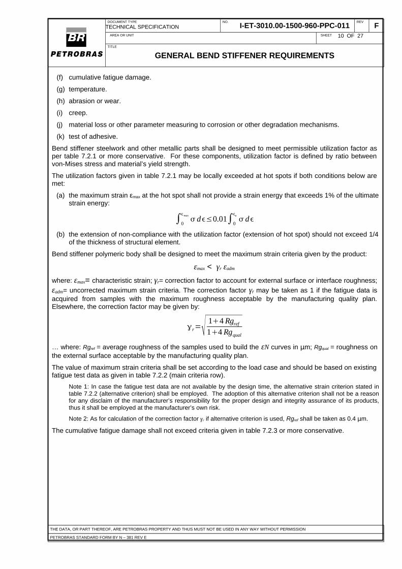
(a) the maximum strain εmax at the hot spot shall not provide a strain energy that exceeds 1% of the ultimatestrain energy:
∫0
max
d≤0.01∫0
u
d
(b) the extension of non-compliance with the utilization factor (extension of hot spot) should not exceed 1/4of the thickness of structural element.
Bend stiffener polymeric body shall be designed to meet the maximum strain criteria given by the product:
εmax < γr εadm
where: εmax= characteristic strain; γr= correction factor to account for external surface or interface roughness;
εadm= uncorrected maximum strain criteria. The correction factor γr may be taken as 1 if the fatigue data isacquired from samples with the maximum roughness acceptable by the manufacturing quality plan.Elsewhere, the correction factor may be given by:
r= 14 Rgref
14 Rgqual
… where: Rgref = average roughness of the samples used to build the εN curves in μm; Rgqual = roughness onthe external surface acceptable by the manufacturing quality plan.
The value of maximum strain criteria shall be set according to the load case and should be based on existingfatigue test data as given in table 7.2.2 (main criteria row).
Note 1: In case the fatigue test data are not available by the design time, the alternative strain criterion stated intable 7.2.2 (alternative criterion) shall be employed. The adoption of this alternative criterion shall not be a reasonfor any disclaim of the manufacturer’s responsibility for the proper design and integrity assurance of its products,thus it shall be employed at the manufacturer’s own risk.
Note 2: As for calculation of the correction factor γr if alternative criterion is used, Rgref shall be taken as 0.4 μm.
The cumulative fatigue damage shall not exceed criteria given in table 7.2.3 or more conservative.
THE DATA, OR PART THEREOF, ARE PETROBRAS PROPERTY AND THUS MUST NOT BE USED IN ANY WAY WITHOUT PERMISSION
PETROBRAS STANDARD FORM BY N – 381 REV E

DOCUMENT TYPE
TECHNICAL SPECIFICATIONNO.
I-ET-3010.00-1500-960-PPC-011REV
FAREA OR UNIT SHEET 11 OF 27
TITLE
GENERAL BEND STIFFENER REQUIREMENTS
Table 7.2.1. Admissible utilization factors for metallic material in bend stiffeners. Service Conditions
InstallationFAT
Normal operation AbnormaloperationAnnual, fatigue Extreme
Functional andenvironmental
Functional,environmentaland accidental
Functional,environmental and
accidental
Functional andenvironmental
Functional,environmental and
accidental
0.67 0.85 0.85 0.67 0.85 0.91
Table 7.2.2. Maximum strain criteria for polymers in bend stiffeners before any correction factor.Service conditions
Installation / abandonment onthe seabed
FAT
Normal operation AbnormaloperationAnnual, fatigue Extreme
PartFunctional andenvironmental
Functional,environmental
Functional,environmentaland accidental
Functional andenvironmental
Functional,environmentaland accidental
Maincrite-r
ion
generalє for N=6×10⁵ є for N= 1.5×10⁵ є for N=5×10⁴ є for N=6×10⁴ є for N=5×10⁴
cyclesє for N=1.5×10⁵
contact &bondedareas
є for N=1.5×10⁵ є for N=2.5×10⁴ є for N=5×10³
cyclesє for N=104
є for N=5×10³
cyclesє for
N=2.5×10⁴
Alter-nativecrite-r
ion
general0.10 єu or 10%,
whichever is less0.15 єu or 15%,
whichever is less0.17 єu or 17%,
whichever is less0.15 єu or 15%,
whichever is less
0.20 єu or 20%,whichever is
less
0.10 єu or10%,
whicheveris less
contact &bondedareas
0.15 єu or 15%,whichever is less
0.22 єu or 22%,whichever is less
0.30 єu or 30%,whichever is less
0.22 єu or 22%,whichever is less
0.30 єu or 30%,whichever is
less
0.20 єu or20%,
whicheveris less
Note 1: єu = elongation at break at 20-25°C.
Note 2: extraordinary care shall be considered in FAT design in order to avoid damage to the polyurethane.Post-test examination shall be carried out in order to avoid the introduction of damage during the FAT.
Table 7.2.3. Admissible cumulative fatigue damage criteria.
application water injection linessupporting one single well
water injection lines to twoor more wells
production/export risers, wellproduction umbilicals
service class as per[1]
low normal high
parts accessible tovisual inspection
1/3 1/6 1/10
parts inaccessible tovisual inspection
1/6 1/10 1/10
Note 1: Some third parties in charge of independent review of calculation or design methodology approval do notaccept admissible cumulative fatigue damage less than 1/10 for any situation.
THE DATA, OR PART THEREOF, ARE PETROBRAS PROPERTY AND THUS MUST NOT BE USED IN ANY WAY WITHOUT PERMISSION
PETROBRAS STANDARD FORM BY N – 381 REV E

DOCUMENT TYPE
TECHNICAL SPECIFICATIONNO.
I-ET-3010.00-1500-960-PPC-011REV
FAREA OR UNIT SHEET 12 OF 27
TITLE
GENERAL BEND STIFFENER REQUIREMENTS
7.3 RISER ANALYSIS USING MODELS FOR BEAMS WITH VARIABLE CROSS-SECTION
In early design stages, the riser analysis may use simplified models consisting of bidimensional beams withvariable cross-section under tension and shear force. They shall comply with the following requirements:
(a) methods and tools shall be validated as per requirements in section 5.2 of [1].
(b) the equivalent beam’s bending stiffness shall be iteratively updated over the analysis to take intoaccount the effects from material non-linearity, including the differences in behaviour as the material isunder tension or compression.
(c) if the bend stiffener’s neutral position is offset, effects from initial curvature shall be included in themodel. If possible, effects from creep should be included too.
Note 1: the design requirement (e) in section 7.0 shall be considered.
(d) if the straight pipe’s bending stiffness is of same order of magnitude of the bend stiffener’s, the modelshall also consider the variation of flexible pipe’s bending stiffness as function of curvature and tension(and internal pressure, as applicable). Such variation may be neglected if the flexible pipe’s bendingstiffness is not significant as compared to bend stiffener’s or if the variation of such stiffness is small.
Note 1: suitable analytical regressions can be used to represent the flexible pipe’s bending stiffness, provided thatthey are properly calibrated by experiments or accredited methods of local analysis.
(e) the methodology shall also verify the fulfilment of requirements on stress components and fatigue givenby sections 5 and appendix C of [1].
Note 1: suitable utilization factors as per table 6 in [1].
Note 2: analytical regressions for determining stress components at each layer can be included in the methodologyto prevent the need of costly detailed local analysis in this phase, provided that they are properly calibrated byexperiments or accredited methods of local analysis.
(f) whenever analyses concerning pipe or umbilical’s integrity are done by bend stiffener’s manufacturer,they shall be checked and, if necessary, redone by the pipe or umbilical supplier, considering its accessto more detailed information of its product.
In order to check preliminary design feasibility and to support the bellmouth design, the following data shallbe calculated:
(a) maximum pipe curvature.
(b) maximum stress components at pipe or umbilical.
(c) maximum strain at bend stiffener conical body.
(d) maximum loads (shear force and bending moment) at conical body’s root, as well as the distance to beconsidered in estimation of loads transferred to bellmouth or end-fitting, as applicable.
7.4 INTERFACE DESIGN
The interface to production vessel or platform shall be design as per purchaser specification. Boltedconnections shall be designed for diver-assisted make-up or for diverless operation using either mechanicalor hydraulic tools. Diver-assisted make-up shall be carefully studied in terms of ergonomics, becausemisdone assembly is a common failure driver for this equipment. Visual inspection should be feasible aspossible.
The guidelines for sliding bend stiffener cap’s dimensions are given in specific ET such asI-ET-3010.xx-1300-279-PPC-yyy [3]. Whenever applicable, the structural ribs of the ending sleeve shall bealigned to the cap cylindrical surface or a smooth transition shall be made to avoid teeth which may hinderthe pull-in operation. The gap between bend stiffener cap and the bellmouth shall be optimized in view of:
(a) manufacturing tolerances.
(b) efficient force transmission.THE DATA, OR PART THEREOF, ARE PETROBRAS PROPERTY AND THUS MUST NOT BE USED IN ANY WAY WITHOUT PERMISSION
PETROBRAS STANDARD FORM BY N – 381 REV E

DOCUMENT TYPE
TECHNICAL SPECIFICATIONNO.
I-ET-3010.00-1500-960-PPC-011REV
FAREA OR UNIT SHEET 13 OF 27
TITLE
GENERAL BEND STIFFENER REQUIREMENTS
(c) mitigation of vibration and misalignment problems.
(d) pull-in feasibility as per conclusions of analysis described in section 7.7.
(e) interface design shall consider, as well, drawings supplied in the related I-RM.
The cap shell thickness shall be designed to withstand the forces and the moments during pull-in (maximumefforts can be in the beginning of the pull-in operation, refer to item (o) of section 6.1) and, as applicable, toavoid its collapse in the abandonment condition.
7.5 THERMAL ANALYSIS
When required, the manufacturer shall perform thermal analysis. This analysis should be performed usingFEM, taking into account most important parameters such as air and seawater temperature and theirconvective actions, insulating effects, air and water-filled gaps, sunlight and heat generated from internal flowtemperature, etc. Allowable temperature criteria for constitutive materials and adhesives (as applicable) shallbe defined as design premises.
7.6 STRUCTURAL ANALYSIS
The manufacturer shall verify the compliance of applicable functional and design criteria using accreditedmethods. Preferential method of structural analysis is FEM. In general, the structural analyses performed inthis phase generally profit from results obtained in preceding analyses and simplifications are acceptable,provided that all applicable criteria are checked and data for additional analysis are suitably produced.
Under the scope of validation of design methodologies, the following rules apply on the structural analysis ofcomponents:
(a)-(c) as per requirements of section 7.3 of this ET.
(f) FE software, if used, shall be validated using widely accepted benchmark tests such as NAFEMS [14].
(g) the analyst shall be warned that FE method is not good at calculation of peak stresses at holes, filletsand other stress raisers (see COOK [15]), thus the straightforward use of extreme FE-predictedstresses as hot spot stresses is discouraged, alternative stress extrapolation methods – e.g.: methoddescribed in DNV RP C203 [16] – shall be made available.
(h) in addition to the foregoing warning, the concept of stress concentration factor (SCF) shall also be usedwith care, since its definition is often ambiguous and non-adherent to experimental evidences,especially in the fatigue performance assessment (see ROUSSIE [17]).
In general, structural analysis treated herein comprises the following verifications:
(a) cumulative fatigue damage, maximum stress and strain criteria in welds, steelwork and polymeric body.
Note 1: the verification of static strength and fatigue of fasteners can be performed using accredited analyticalmethods instead of FEA.
Note 2: if the local effects from contact between flexible pipe and bend stiffener are negligible, instead ofincorporating the pipe into the model and enforcing that contact pair, the analyst may replace it by pressure fieldson the internal bore, standing for contact forces between pipe and bend stiffener. The pressure fields may befound from distributed forces calculated as per section 7.3. The method for extrapolation of pressure fields fromdistributed forces shall be validated by IVA.
Note 3: if the aforementioned distributed loads are not used in replacement for pipe, special care shall be taken toembody the conflicting stiffness properties in the model of flexible pipe: very high radial stiffness, high axial stiffnessand low bend stiffness. The analyst shall verify if resulting bend stiffness is not erroneously high due to impropermodelling effects (e.g.: pipe as stiff fibre displaced from neutral axis).
(b) creep associated to steady curvature.
Note 1: analysis shall consider items (e) of section 7.0, (h) of section 7.1 and (c) of section 7.3.
(c) adhesion assurance in bonded interfaces, where applicable.
Note 1: whenever possible, the manufacturer shall assess the effects from partial debonding.
THE DATA, OR PART THEREOF, ARE PETROBRAS PROPERTY AND THUS MUST NOT BE USED IN ANY WAY WITHOUT PERMISSION
PETROBRAS STANDARD FORM BY N – 381 REV E

DOCUMENT TYPE
TECHNICAL SPECIFICATIONNO.
I-ET-3010.00-1500-960-PPC-011REV
FAREA OR UNIT SHEET 14 OF 27
TITLE
GENERAL BEND STIFFENER REQUIREMENTS
Note 2: the manufacturer shall propose a model for evaluating the debonding mechanism in terms of extreme loadsand cumulative effects.
(d) waterproofing (sealability) in areas not deemed to be able to undergo wet conditions (in accordance todesign premises).
Note 1: in general, most critical case is the seabed storage: high external pressure combined to pure bending. Ifthe manufacturer cannot assess the storage curvature, MBR shall be taken.
(e) performance sensitivity studies, in view of variations of manufacturing tolerances and materialproperties within allowable limits.
Note 1: this study obtains information necessary to compose the manufacturing quality report.
7.7 PULL-IN FEASIBILITY STUDY
When required by the purchaser in the due I-RM, the pipe or umbilical supplier shall carry out computationalsimulations of the pull-in operation using virtual prototypes. Pull forces, self-weight, tensions in pull-in breakwires (and their actual application points), bend stiffener, pulling head, bellmouth and i-tube’s geometry -including adverse combinations of tolerances - and misalignments shall be included into the simulation.
8.0 MATERIALS
The constitutive materials shall be compatible with bend stiffener’s functional and design requirements.Material qualification for service shall be done using applicable requirements of section 6.2 of [1] and section6 and 7 of ISO 13628-2 [18]. The manufacturer is responsible for material selection, hence the identificationof particular failure mechanisms from which each material can suffer and their mitigation are under its scopeof work.
Material properties shall be obtained by trials whenever possible. Exceptionally, if conditions like those citedin section 5.1 are met, other sources of information can be used, provided that they are accredited andcertified by IVA. Test shall be performed in accordance with documented practices and, as applicable, withinstandard test procedures. If test methods are not specified by purchaser and/or no international standard testprocedure is available, the manufacturer may use its own methods and criteria or other developed by the rawmaterial supplier. Material tests should be redone when:
(a) new prototype is obtained by change of materials.
(b) the raw material supplier is changed.
(c) any doubt arises on the quality of a representative lot of material.
Material tests shall be certified by an IVA; the test records and certificates shall be kept on file for thepredicted product’s service time.
Test samples shall be extracted from processed material, instead of raw material. In absence of statisticallyrepresentative number of tests, the most unfavourable test results shall be considered. Formal acceptanceand rejection criteria shall be proposed by manufacturer and approved by an Independent Verification Agent(IVA), provided its correlation to the design requirements.
8.1 REQUIREMENTS FOR POLYMERS
The information on physical, chemical and mechanical properties of polymers shall be collected at theoperational temperature range. The following properties shall be acquired and documented:
(a) stress-strain curves gauged at 200%-strain per minute rate and ranging from -20- to 20%-strain.
Note 1: curves gauged at 100%-strain per minute rate can be accepted under PETROBRAS agreement.
(b) ultimate strength and elongation at break.
(c) Young’s modulus at 5- or 6%-strain.
(d) admissible range of temperature.THE DATA, OR PART THEREOF, ARE PETROBRAS PROPERTY AND THUS MUST NOT BE USED IN ANY WAY WITHOUT PERMISSION
PETROBRAS STANDARD FORM BY N – 381 REV E

DOCUMENT TYPE
TECHNICAL SPECIFICATIONNO.
I-ET-3010.00-1500-960-PPC-011REV
FAREA OR UNIT SHEET 15 OF 27
TITLE
GENERAL BEND STIFFENER REQUIREMENTS
(e) creep parameters.
(f) fatigue data or criteria.
(g) density.
(h) abrasion against the material of the flexible pipe or umbilical’s external sheath.
(i) list of chemical products, which may be found during handling or operation, which are harmful.
Besides those, the following information on materials shall be acquired and considered in design:
(j) variation of mechanical properties due to temperature and Mullins’ effect.
(k) manufacturing limitations and requirements.
(l) resistance to exposition to hydraulic oil, diesel oil, grease, solvents, lubricant and petroleum, asapplicable.
This information shall be submitted to IVA and kept accessible to purchaser’s personnel.
When not subject of special agreement between purchaser, IVA and manufacturer, test procedures forpolymers shall follow procedures referred in table 8.1.1.
Table 8.1.1. Test procedures for polymeric materials
Tests ASTM DIN ISO
Density D-792 [19] 1183 [20]
Hardness D-2583 [21] 868 [22]
Tear strength D-624 [23] 34 [24]
Tensile properties D-638 [25] 53504 [26] 527[27] or 37 [28]
Compression set D-695 [29] 815 [30]
Rotating drum abrader D-5932[32] 4649 [33]
Rubber reel test G-65 [34]
Oil and solvent resistance D-471 [35] 53428 [36]
Hydrolytic stability D-3137 [37] 2440 [38]
Heat ageing D-573 [39] 53508 [40] 188 [41]
8.2 REQUIREMENTS FOR METALLIC MATERIALS
The bend stiffener manufacturer shall acquire and record the following mechanical properties:
(a) yield and ultimate strength.
(b) elongation at break.
(c) Young’s modulus.
(d) stress-strain curves.
(e) hardness and impact strength.
THE DATA, OR PART THEREOF, ARE PETROBRAS PROPERTY AND THUS MUST NOT BE USED IN ANY WAY WITHOUT PERMISSION
PETROBRAS STANDARD FORM BY N – 381 REV E

DOCUMENT TYPE
TECHNICAL SPECIFICATIONNO.
I-ET-3010.00-1500-960-PPC-011REV
FAREA OR UNIT SHEET 16 OF 27
TITLE
GENERAL BEND STIFFENER REQUIREMENTS
(f) fatigue data, preferentially SN curves for representative values of mean stress.
(g) manufacturing limitations.
8.3 CORROSION RESISTANT ALLOYS
Under the scope of this ET, the metallic materials considered as CRA are:
(a) Alloy 625 (UNS N06625, as per ASTM B443, B444 or B446, whichever is applicable)
Exceptionally, the following alloys can be accepted for bend stiffeners used in umbilical and water injectionlines supporting one single well:
(a) Alloy C-276 (UNS N10276, as per ASTM B564, B574, F468 and F467, whichever is applicable)
(b) Alloy 718 (UNS N07718), only if the requirements of API 6A-718 [42] are met.
Provisions in DNV RP B-401 [43] shall be fulfilled for abovementioned materials.
CRA materials shall be used in:
(a) components with complex or occluded geometry, including the reinforcement structures (torus), theirrespective stud bolts and fasteners.
(b) regions where cathodic protection may not work properly or is not available (such as internal areas ofcomponents, etc.).
The hardness of CRA materials shall be limited to 32 HRC or equivalent. The microstructure of CRAmaterials for stud bolts, screws, nuts and related items shall be controlled in order to assure that theirmechanical strength is similar to conventional materials, as given by ASTM A193 [44] for bolts and ASTMA194 [45] for nuts.
The electrochemical compatibility between CRA material and other metals shall be verified by themanufacturer and confirmed by the IVA; design solutions shall be afforded to avoid galvanic corrosion.
Instead of CRAs, coatings such as interdiffused electroless nickel (9-13% phosphorous) and epoxy coatingon surface of carbon or low alloy steels may be applied, under purchaser and IVA approval:
(a) in parts where cathodic protection alone might be less effective, with the additional restriction that theanodes shall be specified to give full corrosion protection for the entire component’s life, consideringpredicted coating breakdown factor over coating life.
The efficiency of aforementioned coatings shall be established by accelerated corrosion trials (bench tests)in addition to successful track records (in-field tests), witnessed and certified by IVA.
8.4 REQUIREMENTS FOR ADHESIVE MATERIALS
The specification of the adhesive product shall consider possible coatings on the metal surfaces (ifapplicable), extreme debonding forces, ageing, dynamic loads and operational and temperature. Favourablebonding interface condition shall be guaranteed by manufacturing process and quality control to avoid rustand unsuitable surface conditions.
In agreement with the design premises, if the adhesion is assumed to be critical for the good operation andintegrity of the bend stiffener, then the manufacturer shall offer evidences that it will keep effective all thedesign life long. Test procedures should be run as per ISO 4624 [46], ASTM D4521[47], ASTM D3528 or anyother reasonable methods agreed by manufacturer and IVA.
9.0 GENERAL PROTOTYPE TESTING
The prototype qualification programme shall be established by the pipe or umbilical supplier and submitted topurchaser. This programme shall encompass all relevant characteristics of design and manufacture such as,but not limited to, design loads, temperature and materials.
THE DATA, OR PART THEREOF, ARE PETROBRAS PROPERTY AND THUS MUST NOT BE USED IN ANY WAY WITHOUT PERMISSION
PETROBRAS STANDARD FORM BY N – 381 REV E

DOCUMENT TYPE
TECHNICAL SPECIFICATIONNO.
I-ET-3010.00-1500-960-PPC-011REV
FAREA OR UNIT SHEET 17 OF 27
TITLE
GENERAL BEND STIFFENER REQUIREMENTS
The prototype qualification shall consist, at least, of an alternate (dynamic) bending test in real scale. Staticbending tests may also be specified in I-RM or technical specification of product development.
Typically, the functional limits of flexible pipe or umbilical define the design envelope, therefore the bendstiffener prototype tests are usually performed in conjunction with the prototype tests of pipe or umbilical.
9.1 STATIC BENDING TEST
The purposes of the static bending test are to check:
(a) if the bend stiffener’s deflections have good correlation with those predicted at design stage;
(b) if the bend stiffener meets certain functional requirements herein mentioned, especially those related tothe flexible pipe’s integrity.
The bending test is not a bending-on-sheave test; the test configuration is similar to dynamic fatigue test asper section C.2.7 in [1]. Instead of dynamic fatigue, however, combinations of tension and bending momentare applied in order to track conditions in which the pipe achieves the dynamic MBR, provided that otherdesign bounds are not exceeded.
The test rig should preferentially be able to simulate the effects misalignment and dimensional tolerancesgiven in the design premises report.
Photographs of the deformed structure against a referential frame or ruler shall be taken whenever possible.The data acquisition system shall continuously log and store the following gauges:
(a) deflection at a minimum of 3 points.
(b) pulling load at pipe edge.
(c) rotary table rotation, if the test rig can allow for the angle tolerance as stated in the section 7.0, item (f).
(d) temperature.
(e) pipe or umbilical’s free curvature.
The acceptance criteria for the static bending test shall be proposed by the manufacturer, based on thecompliance of aforementioned functional and design requirements.
9.2 DYNAMIC FATIGUE TEST AND DISSECTION AFTER TESTING
The manufacturer shall execute these trials as per the specific I-RM or, in lack of specific reference, as pernon-standardized test specification I-ET-3500.00-6500-291-PAZ-001 [2] for risers andI-ET-3000.00-1500-29B-PAZ-006 [48] for umbilical cables. Whenever the dynamic fatigue test also aims atqualifying some flexible pipe prototype, the adherence to [2] or [48] shall be duly assured. If it aims atqualifying the bend stiffener prototype only, the following modifications may be agreed betweenPETROBRAS, the manufacturer and the IVA, as applicable:
(a) review of any manufacturing reports of the bend stiffener and flexible pipe samples in order to knowabout extreme deviations and non-conformity treatments that might influence the test results or thatmight be matter of future justification of insufficient performance.
(b) fine-tuning of polyurethane superficial roughness at critical bend stiffener section to the extreme of theacceptance criteria as per manufacturer’s quality management system.
(c) reduction of the number of cycles to 1,000,000 cycles or less, if the condition (d) below is met.
Note 1: the engineer in charge of test planning should assess pipe fatigue life in order to mitigate the risk of a pipefailure during the test execution. Although the pipe failure may be acceptable when the dynamic fatigue testfocuses on the bend stiffener prototype, it usually hinders the test execution and arises doubts about theeffectiveness of the bend stiffener.
(d) inclusion of extreme angles and forces (usually related to extreme and accidental load conditions),taking number of cycles exceeding 10.
THE DATA, OR PART THEREOF, ARE PETROBRAS PROPERTY AND THUS MUST NOT BE USED IN ANY WAY WITHOUT PERMISSION
PETROBRAS STANDARD FORM BY N – 381 REV E

DOCUMENT TYPE
TECHNICAL SPECIFICATIONNO.
I-ET-3010.00-1500-960-PPC-011REV
FAREA OR UNIT SHEET 18 OF 27
TITLE
GENERAL BEND STIFFENER REQUIREMENTS
Note 1: if the assessment of extreme and accidental loads for actual application is not made available by the timeof test execution, tests should be planned considering the extreme values of pipe curvature and polymer strain asper design methodology.
Note 2: the extreme loads should preferentially be applied before the fatigue blocks.
Note 3: the availability of test rigs shall be verified beforehand, in order to avoid excessive limitation of options.
(e) inclusion of pipe centreline transverse displacement (at 4 points) and transverse bending load (force athydraulic actuator) into the list of data to be monitored.
Note: the transverse displacements shall be predicted in the phase of test planning and shall be informed to thetechnicians in charge of test rig control and test witnessing. If the measured displacements deviate from thepredicted displacements very much, the involved parts shall decide if the fatigue load parcels have to bereassessed before going further testing, acknowledged that the actual curvatures and damage contributions fromeach parcel wouldn’t be within the planned values.
(f) visual inspection at end of every fatigue parcel and at every 20,000 cycles during test.
Note: the photography of surface of the most critical polyurethane sections and of visible metallic parts susceptibleto crack propagation is recommended.
Formal acceptance and rejection criteria for the dynamic test and the dissection shall be proposed by themanufacturer or supplier and shall be approved by the IVA and purchaser.
The presence of internal voids or inclusions in the polymeric body, cracks in the steelwork, unbonded areaswhich should be bonded (according to design premises) and other non-conformities which could not befound by other non-destructive methods shall be carefully investigated during dissection. The dissection planshall contemplate the areas where these defects are most probable to occur and where their existence ismore hazardous.
9.3 PULL-IN TEST
The pulling test shall be performed if required within the scope of I-RM. Its main purpose is to verify the bendstiffener performance in the pull-in operation, especially in the bend stiffener cap insertion into the bellmouth,as well as its suitable locking at the position and easy removal.
10.0 PROCESS OF MANUFACTURE
All processes of manufacture and related work instructions shall be documented in a manufacturing qualityplan (MQP) or similar, as per ISO 9000 standards. Specific I-RM should establish requirements formanufacturing processes which replace those given herein. In lack of more precise specifications in properdocumentation, the regulations in this section apply.
MQP shall include, at least:
(a) requirements on raw materials, statements of applicable scope and processing limits, acceptancecriteria and inspection techniques.
(b) sequence and description of processes of manufacture.
(c) applicable machinery adjustments.
(d) specification and procedures for mould preparation, moisture of constituents, injection into mould,curing, mould removal and finishing of the polymeric body.
(e) inspection techniques and acceptance criteria for dimensions, surface roughness, coating thickness,surface or internal defects and other quality assurance parameters for each part of the bend stiffener.
(f) specification for adhesive, its preparation (including surface treatments, as applicable) and application.
(g) welding procedure specifications (WPS), welding personnel qualification requirements, specifications ofnon-destructive examination (NDE) and heat treatment.
(h) procedures for attachment of anodes for cathodic protection, as applicable.
THE DATA, OR PART THEREOF, ARE PETROBRAS PROPERTY AND THUS MUST NOT BE USED IN ANY WAY WITHOUT PERMISSION
PETROBRAS STANDARD FORM BY N – 381 REV E

DOCUMENT TYPE
TECHNICAL SPECIFICATIONNO.
I-ET-3010.00-1500-960-PPC-011REV
FAREA OR UNIT SHEET 19 OF 27
TITLE
GENERAL BEND STIFFENER REQUIREMENTS
(i) repair procedures, as applicable.
(j) description of factory acceptance tests and their acceptance criteria.
(k) requirements on handling and storage.
(l) needs for marking, documentation and traceability of raw material, specifications, records and othersources of information.
(m) non-conformity treatment procedures.
(n) inspection points and policy.
(o) description of staff responsibilities.
Criteria and requirements in MQP shall be practicable and in harmony with design assumptions. Informationtherein included are mostly manufacturer’s proprietary knowledge, but a comprehensive MQP abstract shallbe available, on purchaser’s request, to document:
(a) the solidness of the manufacturing quality procedures.
(b) manufacturing parameters to be verified by sample dissection after qualification tests.
Manufacturing allowances shall be specified on statistical foundations by the manufacturer’s technical staff.Adverse combinations of parameters within allowed ranges shall not initiate failure mechanisms undetectableby factory acceptance tests (FATs). The MQP shall also consider ergonomic and geometrical constraints,especially if the adhesive between polyurethane and steelwork is applied manually or by spray.
Dimensional tolerances for all dimensions, as per item (f) of this section, shall be included in engineeringdrawings. These tolerances shall be verified in the design process to be acceptable, such that the functionalrequirements are unaffected by variations within the specified tolerances.
Main steps in the manufacturing process shall be subject to inspection. The manufacturer shall record everyverified non-conformity. The manufacturing plan shall prevent long period of time between inspection andfollowing manufacturing phases, especially if the metallic surfaces are exposed to atmospheric or pittingcorrosion.
Considerations should be given to applying a suitable fixing method onto the bolt, in order to prevent fromloosening due to vibrations.
The constituent raw materials for polymers shall be mixed in ratios specified in the MQP. When mixingpolymeric material components, care shall be taken on the resulting temperatures from exothermic reactions.They shall not cause damaging residual stresses which may result in functional requirements not beingsatisfied. For each mix of polymeric material, a sample of material shall be retained and tested to check if it isconsistent with the properties measured in the qualification tests. The following properties shall be tested asa minimum:
(a) tensile strength.
(b) hardness.
(c) stress–strain curve for the strain range considered in the design (tension and compression).
10.1 INSPECTIONS AND MINIMUM REQUIREMENTS FOR SURFACE FINISHING
For the purpose of inspection, some type of classification of the importance of the local surface finishing inthe global structural integrity is strongly recommended, acknowledged that flaws or increased roughness atsections undergoing excessive strains cannot be acceptable, whereas some certain amount of flaws canexist at sections undergoing low strains with no major consequence to the equipment endurance. In order toprovide such classification herein, the following classes of surface finishing are given:
• M1: metallic surfaces that may get in contact with polyurethane, free of adhesives, by which loadtransfer is expected to occur and at which the local components of strain in the neighboringpolyurethane can exceed 3% in any fatigue condition or 10% in extreme or accidental conditions.
THE DATA, OR PART THEREOF, ARE PETROBRAS PROPERTY AND THUS MUST NOT BE USED IN ANY WAY WITHOUT PERMISSION
PETROBRAS STANDARD FORM BY N – 381 REV E

DOCUMENT TYPE
TECHNICAL SPECIFICATIONNO.
I-ET-3010.00-1500-960-PPC-011REV
FAREA OR UNIT SHEET 20 OF 27
TITLE
GENERAL BEND STIFFENER REQUIREMENTS
• M2: metallic surfaces that may get in contact with polyrethane, free of adhesives, by which load transferis expected to occur and and at which the local components of strain in the neighboring polyurethaneare not expected to exceed 3% in any fatigue condition nor 10% in extreme or accidental conditions.
• M3: metallic surfaces in general.
• P1: polyurethane surfaces where any component of strain exceeds 3% in fatigue conditions or 10% inextreme/accidental conditions.
• P2: external polyurethane surfaces where any component of strain is not expected to exceed 1% infatigue conditions nor 3% in extreme/accidental conditions.
• P3: general polyrethane surfaces (i.e.: bore).
Note: for intermediate bend stiffeners, under agreement of PETROBRAS and IVA, regions whichwould normally be classified as M1 and P1 can be downgraded to M2 and P2 or even M3 and P3.
The bend stiffener designer shall inform the due classification of the surfaces in the manufacturing drawingsdelivered to the bend stiffener manufacturer.
The surface of metallic components shall be visually examined for flaws, including dents, cracks, scratches,shavings, gouges, corrosion and discolteria for such defects shall be stated in the MQP, based on duerequirements for mitigation of failure mecoration areas such as blurring, scorching, staining, exceptdiscoloration at welds. NDT of welds shall be performed in accordance with suitable international standard.
Before application of adhesive to metallic parts, the manufacturer shall ensure that surfaces are clean, withdue roughness and free from dust or dirt and are prepared properly. When handling a metallic part which hasbeen coated by adhesive, care shall be taken to avoid damaging this coating. The manufacturer shall find outthe maximum time for which the metallic parts with adhesive can be stored before moulding, considering atime in which bonding efficiency is not affected substantially. The manufacture shall comply with this timelimit.
The surface of polyrethane body shall also be visually examined for flaws. Requirements for inspections ofsurfaces within the class P1 shall be matter of tighter criteria defined in the MQP. When finishing the surfaceof bend stiffener body, i.e. by activities such as grinding of bubbles or taking flash off, extreme care shall betaken not to leave cuts or punctures on surfaces, which might initiate a failure in the bend stiffener body.
The surface roughness shall not exceed the following criteria:
• 4 μm for surfaces classified as M1 and P1.
• 6 μm for surfaces classified as M2 and P2.
• 15 μm for surfaces classified as M3 and P3.
The occurrence of bubbles in polyurethane is subjected to the following criteria:
• No bubble exceeding 3 mm is acceptable on surfaces classified as P1.
• No bubble exceeding 6 mm is acceptable on surfaces classified as P2.
• The equivalent bubble – evaluated from the sum of diameters of two neighboring bubbles – shall notexceed 150% of the allowable diameter. Two bubbles are considered to be neighbors if the distancebetween them is less than the diameter of the largest bubble. Bubbles with diameter of less than 0,7mm can be disregarded for application of this criterion.
10.2 BOLT TORQUE AND PRE-LOAD PRECISION
The manufacturer shall provide studies on the uncertainty that may exist in the bolt pre-load and torque. Noconcern is necessary when the bolt pre-load is given by hydraulic tensionner. When conventionaltorquimeter is used, the uncertainty can raise up to ±20% or more, thus the design shall account for bothlack and excess in preload, by due assumptions in the structural analyses. If the analysis results point risk ofpremature failure, proper control means shall be proposed, such as the use of hydraulic tensionner to make
THE DATA, OR PART THEREOF, ARE PETROBRAS PROPERTY AND THUS MUST NOT BE USED IN ANY WAY WITHOUT PERMISSION
PETROBRAS STANDARD FORM BY N – 381 REV E

DOCUMENT TYPE
TECHNICAL SPECIFICATIONNO.
I-ET-3010.00-1500-960-PPC-011REV
FAREA OR UNIT SHEET 21 OF 27
TITLE
GENERAL BEND STIFFENER REQUIREMENTS
the assembly at the safest level of preload. When more reliable sources are unavailable, the table below(extracted from Machinery's Handbook[49]) shall be used.
Table 10.2.1. Accuracy of bolt preload application methods (from Machinery's Handbook [49]).
Method Accuracy Method Accuracy
By feel ±35% Computer-controlled wrench
Torque wrench ±25% below yield (turn-of-nut) ±15%
Turn-of-nut ±15% yield-point sensing ±8%
Preload indicating washer ±10% Bolt elongation ±3−5%
Strain gages ±1% Ultrasonic sensing ±1%
10.3 NON-CONFORMITY REPORT (NCR) AND NON-CONFORMITY TREATMENT REPORT (NCTR)
NCRs and NCTRs shall be prepared under conditions given in specific I-RM. In lack of proper specification,the regulations in this section apply.
Non-conformity report (NCR) shall be prepared shortly after any non-conformity is found and anon-conformity treatment report (NCTR) shall be prepared after the careful investigation of causes andeffective actions to mitigate the repetition of the non-conformity are suggested. Non-conformity reports(NCRs) shall be generated when one of the following occurrences is found, at least:
(a) a divergence between the documented procedures and the actual practices.
(b) the break of documented allowable limits for material properties, dimensions and other fabrication andmounting parameters.
(c) any unexpected hazard or defect, which can influence the material or bend stiffener’s integrity andperformance, is found during fabrication or mounting.
(d) the product is not approved during qualification or factory acceptance tests.
(e) the product experiences damage during transportation, installation or operation.
NCR shall include detailed information about the non-conformity, the detection method and proper subsidiesfor the identification of its causes and its driver mechanisms.
NCTR shall include the conclusions about the cause of non-conformity, the description of its drivermechanisms, the possible consequences, the frequency of occurrence of similar non-conformities in themanufacturer’s plant, the suggested actions to mitigate future occurrences and the actions which areimplemented by the date of emission of the NCTR.
The list of identified non-conformities, indexes to the NCRs and NCTRs and quality indicators shall becommunicated to purchaser before the delivery of the product. Copies of the NCRs and NCTRs shall bedelivered to the final client as part of the product documentation. When IVA is engaged in the prototypecertification, it shall be allowed to access the NCRs and NCTRs pertaining to similar products, in order tocheck if the operational practices of the manufacturers are compatible with the needs.
10.4 FAT
Factory acceptance tests (FATs) consist, at least, of:
(a) visual and dimensional inspection: the surface of finished polymeric parts shall be visually examined forany obvious flaws such as warping, cracks, scratches, bubbles, discoloration or indentations. Any flawsverified to exceed allowable limits stated in the manufacturer documented procedures shall be treated
THE DATA, OR PART THEREOF, ARE PETROBRAS PROPERTY AND THUS MUST NOT BE USED IN ANY WAY WITHOUT PERMISSION
PETROBRAS STANDARD FORM BY N – 381 REV E

DOCUMENT TYPE
TECHNICAL SPECIFICATIONNO.
I-ET-3010.00-1500-960-PPC-011REV
FAREA OR UNIT SHEET 22 OF 27
TITLE
GENERAL BEND STIFFENER REQUIREMENTS
as per MQP. Dimensional FAT tests shall verify that the bend stiffener is in accordance withengineering drawings. Special care shall be taken with the measurement of surface roughness incritical areas, which shall never exceed the criteria given in section 10.1.
(b) tests of polymer samples mentioned in the last paragraphs of section 10.0.
10.5 REPAIRS
Repairs will be accepted only in case a previous certified procedure, considering all concerns related to theproduct use, in special those regarding fatigue, and when defined limits for repairable defects, is available.Average surface roughness in repaired areas is exceptionally tolerated to exceed the abovementionedbounds, but shall never exceed the value given by:
Rgmax=min[ 58
%, fatigue2 ,
234
%, extreme 2 ]−0.25
… where: Rgmax = maximum allowable roughness in μm; % = maximum amplitude (maximum minusminimum, considering fatigue and extreme load conditions) of strain at location, in percentual strain(informed by bend stiffener designer).
10.6 MARKING
The marking on bend stiffener shall include the following, as a minimum:
(a) Manufacturer name.
(b) Manufacturer serial number for product.
(c) Fabrication date.
(d) Project/application title or tracking number.
The marking shall not vanish over service life. The marking on the bend stiffener shall be enough to directpurchaser personnel to all related documentation straightforwardly.
10.7 HANDLING, STORAGE, TRANSPORTATION AND INSTALLATION
The manufacturer shall document the storage requirements, respecting purchaser’s practices, which shallinclude the following items:
(a) allowable storage temperature.
(b) list of chemicals that may be found during storage, transportation and installation and are especiallyharmful if exposed to.
The procedures for the installation of the bend stiffener shall encompass, at least:
(a) equipment required.
(b) fastening forces for fasteners and straps.
(c) identification of which particular fasteners are to be used for securing a particular component.
(d) step by step installation procedures.
Bend stiffener locations where the maximum strains occur shall be specially protected during handling,storage, transportation and installation in order to avoid any contact or friction that may harm the surface orincrease its roughness from the output of manufacturing plant to the final installation site.
THE DATA, OR PART THEREOF, ARE PETROBRAS PROPERTY AND THUS MUST NOT BE USED IN ANY WAY WITHOUT PERMISSION
PETROBRAS STANDARD FORM BY N – 381 REV E

DOCUMENT TYPE
TECHNICAL SPECIFICATIONNO.
I-ET-3010.00-1500-960-PPC-011REV
FAREA OR UNIT SHEET 23 OF 27
TITLE
GENERAL BEND STIFFENER REQUIREMENTS
10.8 FINAL INSPECTION
The inspections mentioned in item (e) of Manufacturing Quality Plan (see section 10.0) shall be duly carriedout.
11.0 DOCUMENTATION
Bend stiffener documentation shall be in accordance with the principles and regulations for documentation offlexible pipes, umbilicals and related ancillary equipment. Additional requirements for specific documents areherein mentioned. If not properly declared in the specific I-RM, the bend stiffener supplier shall submit ormake available the following documents at the delivery of the product:
(a) installation procedure report as per section 10.5.
(b) MQP abstract, excluding proprietary information unnecessary to attest the product’s quality.
(c) raw material test records or certificates.
(d) non-conformity treatment reports, as applicable, excluding proprietary information which shall not be dis-closed.
(e) factory acceptance test (FAT) reports.
(f) handling and storage recommendations as per section 10.5 of this ET.
11.1 MINIMUM DATA SHEET
The tables below clarify the minimum information to be included in technical proposal.
1 - GENERAL DATABend stiffener identificationAssociated flexible pipe structure identification (ref. item 8.1.3, NI-2409A [1])Reference to specification of interface to fitting devicesReference to project or technical proposalMaximum design temperature (°C)Total length (m)Material used in polymer conical body and its hardness Shore at 23° CTip length (m)Effective length of the conical polymeric body (m)Internal bore diameter (mm)External diameter at tip section (mm)Effective external diameter at root section of the conical body (mm)Specification of metallic material used in capCap’s external diameter (mm)Cap’s length (m)Total weight in air (kgf)Total weight in sea water (kgf)
2 - TECHNICAL DATAMinimum bending radius (or curvature) for storage (m)Minimum bending radius (or curvature) for laying (m)Design curves for extreme top angle and tension (kN and degrees)
THE DATA, OR PART THEREOF, ARE PETROBRAS PROPERTY AND THUS MUST NOT BE USED IN ANY WAY WITHOUT PERMISSION
PETROBRAS STANDARD FORM BY N – 381 REV E

DOCUMENT TYPE
TECHNICAL SPECIFICATIONNO.
I-ET-3010.00-1500-960-PPC-011REV
FAREA OR UNIT SHEET 24 OF 27
TITLE
GENERAL BEND STIFFENER REQUIREMENTS
3- MODULUS OF ELASTICITY (YOUNG’S MODULUS)/TEMPERATURE CURVE
4- SKETCH OF BEND STIFFENER
11.2 DESIGN PREMISES REPORT
The design premise shall contain the parameters as specified in table 15 of ISO 13628-2[6]. If themanufacturer has made assumptions on any of the parameters of the table, then it shall be specified in thedesign premise that the values are assumed. The design premise shall include all technical requirementsand recommendations given in this technical specification and in [1].
Besides that, the design premises report shall contain:
(a) conceptual description of load cases.
(b) requirements for the project.
(c) relevant assumptions to be employed in analysis procedures and design.
(d) design criteria: required safety margins and structural capacities for each bend stiffener component.
(e) environmental limitations: limits for external temperature, pipe’s internal fluid temperature, sunlightexposition, water depth, etc.
(f) possible failure modes, mechanisms and drivers: detailed description of failure modes, mechanisms anddrivers to which the bend stiffener is susceptible shall be presented. The design solution to mitigatethem shall be specified by the manufacturer in this section.
11.3 DESIGN REPORT
The design report shall contain, at least:
(a) material properties: data mentioned in the sections 8.0, 8.1, 8.2, 8.3 and 8.4.
(b) detailed description of bend stiffener: drawings; design data; structural properties and variations due totemperature, pressure and other effects; stiffness; weight (in air and in water); storage and operationminimum bending radius (MBR); end fitting/support structure dimensions and tolerances; interfacerequirements (termination devices, corrosion protection systems, static offset angles); support pointmaximum bending moment; and geometrical restrictions.
(c) bending stiffener performance against loading (if the product is a prototype): details on calculationprocedures which are not covered in (a) and (b); documented basis for stress concentration factors;stress/strain analysis; calculations demonstrating that design satisfies functional requirementsaccounting for variations within manufacturing tolerance envelopes; estimation of volumetric contraction;maximum contact pressure; identification of the weak (limiting) sections.
In order to facilitate the interpretation of the results, the report should contain a summarized table as per theexample below.
THE DATA, OR PART THEREOF, ARE PETROBRAS PROPERTY AND THUS MUST NOT BE USED IN ANY WAY WITHOUT PERMISSION
PETROBRAS STANDARD FORM BY N – 381 REV E

DOCUMENT TYPE
TECHNICAL SPECIFICATIONNO.
I-ET-3010.00-1500-960-PPC-011REV
FAREA OR UNIT SHEET 25 OF 27
TITLE
GENERAL BEND STIFFENER REQUIREMENTS
Performance parameterLoad condition x
Maximum Criterion Ratio
Stress
[MPa] – tensileside
Steelwork welds
Plain steelwork
Bolts and fasteners
Surface debonding/shear atpolymer-metal interface
Stress
[MPa]compres-siveside
Steelwork welds
Plain steelwork
Bolts and fasteners
Surface debonding/shear atpolymer-metal interface
Strain at PU –plain body
Maximum tensile
Maximum compressive
Strain at PU –contact/ bondedareas
Maximum tensile
Maximum compressive
Damage by theservice life
Steelwork welds
Bolts and fasteners
Polyurethane
11.4 TECHNICAL PROPOSAL OF BEND STIFFENER
When required, the technical proposal comprises the following information:
(a) minimum bend stiffener data sheet as per section 11.1.
(b) justification of product not being a prototype, as applicable.
(c) if product is minimum bend stiffener, analysis report comparing performance of proposed product andcheaper engineering solutions as per item (p) of section 7.0.
(d) tables comprising results found by riser analysis (see section 7.3) for each extreme/accidental load case,including: maximum pipe curvature and associated location, maximum strain at polymer and associatedlocation, bending moment and shear forces at the root section of conical body.
(e) assessment of maximum strain at polymer and cumulative damage in the bend stiffener’s steelwork andflexible pipe structure, as applicable, for fatigue load cases.
11.5 INSPECTION AND TEST REPORT
An Inspection Plan shall be submitted to the approval of the purchaser including all relevant operationsduring manufacturing, its descriptions, inspections, hold points, etc. The inspection and test report shallinclude, as a minimum, the requirements of [1].
THE DATA, OR PART THEREOF, ARE PETROBRAS PROPERTY AND THUS MUST NOT BE USED IN ANY WAY WITHOUT PERMISSION
PETROBRAS STANDARD FORM BY N – 381 REV E

DOCUMENT TYPE
TECHNICAL SPECIFICATIONNO.
I-ET-3010.00-1500-960-PPC-011REV
FAREA OR UNIT SHEET 26 OF 27
TITLE
GENERAL BEND STIFFENER REQUIREMENTS
12.0 REFERENCES
[1] PETROBRAS/E&P-CORP/ENGP/IPP/ES, I-ET-3000.00.6500-291-PAZ-038 FLEXIBLE PIPES (REPLACEMENT OFSTANDARD N-2409), REV.0, 2014.
[2] PETROBRAS/CENPES/PDP/TS, I-ET-3500.00-6500-291-PAZ-001 - NONSTANDARDIZED PROTOTYPE QUALIFICATIONTESTS, REV.G, 2014.
[3] PETROBRAS/CENPES/PDP/TS, BELLMOUTH SPECIFICATION (SEVERAL ETS NUMBERED ASI-ET-3010.XX-1300-279-PPC-0YY, WHERE XX IS RELATED TO THE ASSET AND YY IS A SEQUENTIAL ORDER), 2006.
[4] PETROBRAS/CENPES/PDP/TS, I-ET-3010.00-1500-960-PPC-003 DCDE BEND STIFFENER CONCEPTUAL DESIGN,REV.0, 2006.
[5] PETROBRAS/E&P-CORP/ISP/ES, I-ET-3500.00-6500-291-PAZ-026 MATERIAL, PRODUCT AND MANUFACTURERQUALIFICATION REQUIREMENTS – FLEXIBLE PIPES, REV.E, 2012.
[6] PETROBRAS/CENPES/GSUB/GPROJ, ET-3500.00-1516-940-PDS-011 PROJETO DE PROTEÇÃO CATÓDICA PARAEQUIPAMENTO SUBMARINO, REV.F, 2000.
[7] INTERNATIONAL ORGANIZATION FOR STANDARDIZATION, ISO-9000 - QUALITY MANAGEMENT SYSTEMS -FUNDAMENTALS AND VOCABULARY, 3RD ED., SEPTEMBER 2005.
[8] INTERNATIONAL ORGANIZATION FOR STANDARDIZATION, ISO-9001 - QUALITY MANAGEMENT SYSTEMS –REQUIREMENTS, 4TH ED., NOVMEBER 2008.
[9] INTERNATIONAL ORGANIZATION FOR STANDARDIZATION, ISO-9004 - QUALITY MANAGEMENT SYSTEMS –GUIDELINES FOR PERFORMANCE IMPROVEMENTS, 3RD ED., NOVEMBER 2009.
[10] INTERNATIONAL ORGANIZATION FOR STANDARDIZATION, ISO-19011 - GUIDELINES FOR QUALITY AND/ORENVIRONMENTAL MANAGEMENT SYSTEMS AUDITING, 2ND ED., NOVEMBER 2011.
[11] AMERICAN PETROLEUM INSTITUTE, API 17B - RECOMMENDED PRACTICE FOR FLEXIBLE PIPE, 4TH ED., JULY 2008.[12] AMERICAN WELDING SOCIETY, AWS D.1.1 – STRUCTURAL WELDING CODE – STEEL, 22ND ED., 2010.[13] AMERICAN PETROLEUM INSTITUTE, API RP 2RD - DESIGN OF RISERS FOR FLOATING PRODUCTION SYSTEMS
(FPSS) AND TENSION-LEG PLATFORMS (TLPS), 1ST ED., 2006.[14] NATIONAL AGENCY FOR FINITE ELEMENT METHODS AND STANDARDS, THE STANDARD NAFEMS BENCHMARK,
UNITED KINGDOM, 1990.[15] COOK, R.D., FINITE ELEMENT MODELLING FOR STRESS ANALYSIS, JOHN WILEY&SONS INC., 1995.[16] DET NORSKE VERITAS (DNV), RECOMMENDED PRACTICE RP-C203, FATIGUE STRENGTH ANALYSIS OF OFFSHORE
STEEL STRUCTURES, 2010.[17] ROUSSIE, G., BRADLEY, B. SUTTER, P., DESDOIT, E., FATIGUE PERFORMANCE ASSESSMENT OF MECHANICAL
CONNECTORS FOR DEEPWATER APPLICATIONS, PROCEEDINGS OF THE DEEP OFFSHORE TECHNOLOGY (DOT)CONFERENCE, 2004.
[18] INTERNATIONAL ORGANIZATION FOR STANDARDIZATION, ISO 13628-2[19] AMERICAN SOCIETY OF TESTING OF MATERIALS, ASTM D-792 STANDARD TEST METHODS FOR DENSITY AND
SPECIFIC GRAVITY (RELATIVE DENSITY) OF PLASTICS BY DISPLACEMENT, 2013.[20] INTERNATIONAL ORGANIZATION FOR STANDARDIZATION, ISO-1183 PLASTICS -- METHODS FOR DETERMINING
THE DENSITY OF NON-CELLULAR PLASTICS, 2012.[21] AMERICAN SOCIETY OF TESTING OF MATERIALS, ASTM D-2583 STANDARD TEST METHOD FOR INDENTATION
HARDNESS OF RIGID PLASTICS BY MEANS OF A BARCOL IMPRESSOR, 2013.[22] INTERNATIONAL ORGANIZATION FOR STANDARDIZATION, ISO-868 PLASTICS AND EBONITE -- DETERMINATION OF
INDENTATION HARDNESS BY MEANS OF A DUROMETER (SHORE HARDNESS), 2003.[23] AMERICAN SOCIETY OF TESTING OF MATERIALS, ASTM D-624 STANDARD TEST METHOD FOR TEAR STRENGTH
OF CONVENTIONAL VULCANIZED RUBBER AND THERMOPLASTIC ELASTOMERS, 2000.[24] INTERNATIONAL ORGANIZATION FOR STANDARDIZATION, ISO-34 RUBBER, VULCANIZED OR THERMOPLASTIC –
DETERMINATION OF TEAR STRENGTH, 2010.[25] AMERICAN SOCIETY OF TESTING OF MATERIALS, ASTM D-638 STANDARD TEST METHOD FOR TENSILE
PROPERTIES OF PLASTICS, 2010.[26] DEUTSCHES INSTITUTE FÜR NORMUNG, DIN-53504 DETERMINATION OF TENSILE STRENGTH AT BREAK, TENSILE
STRESS AT YIELD, ELONGATION AT BREAK AND STRESS VALUES OF RUBBER IN A TENSILE TEST, 2012.[27] INTERNATIONAL ORGANIZATION FOR STANDARDIZATION, ISO-527 PLASTICS – DETERMINATION OF TENSILE
PROPERTIES, 2012. [28] INTERNATIONAL ORGANIZATION FOR STANDARDIZATION, ISO-37 RUBBER, VULCANIZED OR THERMOPLASTIC –
DETERMINATION OF TENSILE STRESS-STRAIN PROPERTIES, 2011.[29] AMERICAN SOCIETY OF TESTING OF MATERIALS, ASTM D-695 STANDARD TEST METHOD FOR COMPRESSIVE
PROPERTIES OF RIGID PLASTICS, 2010.[30] INTERNATIONAL ORGANIZATION FOR STANDARDIZATION, ISO-815 RUBBER, VULCANIZED OR THERMOPLASTIC –
DETERMINATION OF COMPRESSION SET AT AMBIENT, ELEVATED OR LOW TEMPERATURES, 2011.[31] AMERICAN SOCIETY OF TESTING OF MATERIALS, ASTM D-3489 STANDARD TEST METHODS FOR
RUBBER--MICROCELLULAR URETHANE, 2011. [32] AMERICAN SOCIETY OF TESTING OF MATERIALS, ASTM D-5963 STANDARD TEST METHOD FOR RUBBER
PROPERTY-ABRASION RESISTANCE (ROTARY DRUM ABRADER), 2004.[33] INTERNATIONAL ORGANIZATION FOR STANDARDIZATION, ISO-4649 RUBBER, VULCANIZED OR THERMOPLASTIC --
DETERMINATION OF ABRASION RESISTANCE USING A ROTATING CYLINDRICAL DRUM DEVICE, 2010. [34] AMERICAN SOCIETY OF TESTING OF MATERIALS, ASTM G-65 STANDARD TEST METHOD FOR MEASURING
ABRASION USING THE DRY SAND/RUBBER WHEEL APPARATUS, 2004. [35] AMERICAN SOCIETY OF TESTING OF MATERIALS, ASTM D-471 STANDARD TEST METHOD FOR RUBBER
PROPERTY-EFFECT OF LIQUIDS, REV. A, 2012. [36] DEUTSCHES INSTITUTE FÜR NORMUNG, DIN-53428 DETERMINATION OF THE BEHAVIOUR OF CELLULAR PLASTICS
WHEN EXPOSED TO FLUIDS, VAPOURS AND SOLIDS, 1986.
THE DATA, OR PART THEREOF, ARE PETROBRAS PROPERTY AND THUS MUST NOT BE USED IN ANY WAY WITHOUT PERMISSION
PETROBRAS STANDARD FORM BY N – 381 REV E

DOCUMENT TYPE
TECHNICAL SPECIFICATIONNO.
I-ET-3010.00-1500-960-PPC-011REV
FAREA OR UNIT SHEET 27 OF 27
TITLE
GENERAL BEND STIFFENER REQUIREMENTS
[37] AMERICAN SOCIETY OF TESTING OF MATERIALS, ASTM D-3137 STANDARD TEST METHOD FOR RUBBERPROPERTY – HYDROLYTIC STABILITY, 1981.
[38] INTERNATIONAL ORGANIZATION FOR STANDARDIZATION, ISO-2440 FLEXIBLE AND RIGID CELLULAR POLYMERICMATERIALS – ACCELERATED AGEING TESTS, 2010.
[39] AMERICAN SOCIETY OF TESTING OF MATERIALS, ASTM D-573 STANDARD TEST METHOD FOR RUBBER –DETERIORATION IN AN AIR OVEN, 2004.
[40] DEUTSCHES INSTITUTE FÜR NORMUNG, DIN-53508 TESTING OF RUBBER - ACCELERATED AGEING, 2000.[41] INTERNATIONAL ORGANIZATION FOR STANDARDIZATION, ISO-188 RUBBER, VULCANIZED OR THERMOPLASTIC –
ACCELERATED AGEING AND HEAT RESISTANCE TESTS, 2011.[42] INTERNATIONAL ORGANIZATION FOR STANDARDIZATION, ISO 10423 - PETROLEUM AND NATURAL GAS
INDUSTRIES - DRILLING AND PRODUCTION EQUIPMENT - WELLHEAD AND CHRISTMAS TREE EQUIPMENT, 2009.[43] DET NORSKE VERITAS (DNV), RECOMMENDED PRACTICE B401 - CATHODIC PROTECTION DESIGN, 2010.[44] AMERICAN SOCIETY OF TESTING OF MATERIALS, ASTM A-193 STANDARD SPECIFICATION FOR ALLOY-STEEL AND
STAINLESS STEEL BOLTING MATERIALS FOR HIGH TEMPERATURE OR HIGH PRESSURE SERVICE AND OTHERSPECIAL PURPOSE APPLICATIONS, 2012.
[45] AMERICAN SOCIETY OF TESTING OF MATERIALS, ASTM A-194 STANDARD SPECIFICATION FOR CARBON ANDALLOY STEEL NUTS FOR BOLTS FOR HIGH PRESSURE OR HIGH TEMPERATURE SERVICE, OR BOTH, 2013..
[46] INTERNATIONAL ORGANIZATION FOR STANDARDIZATION, ISO-4624 PAINTS AND VARNISHES - PULL-OFF TESTFOR ADHESION, 2002.
[47] AMERICAN SOCIETY OF TESTING OF MATERIALS, ASTM D-4521 STANDARD TEST METHOD FOR COEFFICIENT OFSTATIC FRICTION OF CORRUGATED AND SOLID FIBERBOARD, 1996.
[48] PETROBRAS/E&P/IPP/ES, I-ET-3000.00-1500-29B-PAZ-006 - QUALIFICATION TESTS FOR CONTROL UMBILICALS,REV. 0, 2010.
[49] OBERG, E., JONES, F.D., RYFFEL, H.H., MACHINERY'S HANDBOOK, 27TH ED., 2008.
THE DATA, OR PART THEREOF, ARE PETROBRAS PROPERTY AND THUS MUST NOT BE USED IN ANY WAY WITHOUT PERMISSION
PETROBRAS STANDARD FORM BY N – 381 REV E