Embed Size (px)
Citation preview

GeneralSpecifications
<<Contents>> <<Index>>
ADMAG AE is the Advanced Engineering designedmagnetic flowmeter, evolved from the field provenADMAG series. ADMAG AE has a dual compartmenthousing providing ease of wiring while isolating theelectronics from the environment. ADMAG AE continuesthe use of dual frequency excitation, which provides quickresponse and noise free output. ADMAG AE excitationmethod and a ceramic lining allow this magneticflowmeter to be applied to an even greater range ofapplications.
FEATURES Fast response and high stability by our unique Dual
Frequency Excitation method. High Accuracy, 0.5% of flowrate. Dual compartment housing separates the wiring section
from the electronics and protects the electronics fromcorrosive environments.
AC/DC power supply common use (100/200V). Commonly available 4-conductor cables used for 24V
DC version. High visibility backlit LCD for easy operation. 99.9% ultra high purity alumina ceramic lining. An integral leak-proof Pt Alumina cermet electrode is
used on flow tubes with ceramic liners. Conform to Pressure Equipment Directive 97/23/EC
STANDARD SPECIFICATIONS Magnetic Flow Converter for AE100MG/MN/SC/MH,
AE200MG/MN/SC/MH, AE300MG/MN; AE14Note 1: For models with no indicator, a hand-held terminal
is necessary to set parameters.Note 2: Pulse output, status output and alarm output use
common terminals, therefore, these functions arenot available at the same time.
Note 3: Please refer to GS01E07F01-00 Fieldbuscommunication type(/FB).
Excitation method: Dual frequency excitationOutput Signal(Note 3):
Current Output: 4 to 20 mA DC (Load resistance 750Ωmaximum).
Transistor Contact Output(Open-collector):Pulse, alarm or status output selected byparameter setting. Contact rating: 30 V DC(OFF), 200 mA (ON).
Communication (option)(Note 3):BRAIN or HART (Superimposed on the 4 to 20 mA DCsignal)Load Resistance: (including cable resistance)
BRAIN: 250 to 600ΩHART: 230 to 600Ω, depending on q’ty of field
devices connected to the loop (multidropmode)
Load Capacitance: 0.22 µF maximumLoad Inductance: 3.3 mH maximumDistance from Power Line:
15 cm(0.6 ft) or more (Parallel wiringshould be avoided.)
Input Impedance of Receiver Connected to the Receiv-ing Resistance: 10kΩ or larger (at 2.4 kHz)
Maximum Cable Length:2 km (6500 ft) (when polyethylene-insulated PVC-sheathed control cables(CEV cables) are used)
Note: HART is a registered trademark of the HARTCommunication Foundation.
Instantaneous Flow Rate Display Function:Flow rate can be displayed either inengineering units or in percent of span.(for models with indicator)
Totalizer Display Function:Totalized volume in any engineering unit canbe displayed by setting a totalizing factor.(for models with indicator)
Damping Time Constant(Note 1):Settable from 0.1 second to 200 seconds(63% response time).
Span Setting Function(Note 1):Volumetric flow setting is available by settingvolume unit, time unit, flow rate value andflow tube size.
Volume Unit: gallon(US), m3, l(litre), cm3,barrel(=158.987L)
Velocity Unit: ft, mTime Unit: sec., min., hour, dayFlow Tube Size: inch, mm
Pulse Output Function(Note 2), (Note 3):Scaled pulse can be output by setting apulse factor.
Pulse Width: Duty 50% or fixed pulse width (0.5, 1, 20,33, 50, or 100 ms) - user selectable.
Output Rate: 0.0001 to 1000pps (when pulse outputfunction is selected.)
Status Output Function(Note 2), (Note 3):One of the following is selected byparameter setting.
• Auto 2 Ranges Status Output:Indicates the selected range for automaticdual range function.
• Forward and Reverse Status Output:Indicates the flow direction for forward andreverse flow measurement mode.
• Totalization Status Output:Indicates that the internal totalized valueexceeds the set value.
• Low Limit Alarm:Indicates that flow rate is under the lowlimit set value.
Models AE100MG/MN/MH/SC, AE200MG/MN/MH/SCand AE300MG/MN Integral Type,Model AE14 Converter, Models AE100DG/DN/DH,AE200DG/DN/DH and AE300DG/DNMagnetic Flowmeter
Yokogawa Electric Corporation2-9-32, Nakacho, Musashino-shi, Tokyo, 180-8750 JapanTel.: 81-422-52-4443 Fax.: 81-422-52-2018
GS 01E07A00-01E
GS 01E07A00-01E©Copyright Jan. 1994(YK)21st Edition Oct. 2005(KP)
AE100/200/300[Style:S2], AE14[Style:S1]
2<<Contents>> <<Index>>
GS 01E07A00-01E 21st Edition Oct. 20, 2005-00All Rights Reserved. Copyright © 1994, Yokogawa Electric Corporation
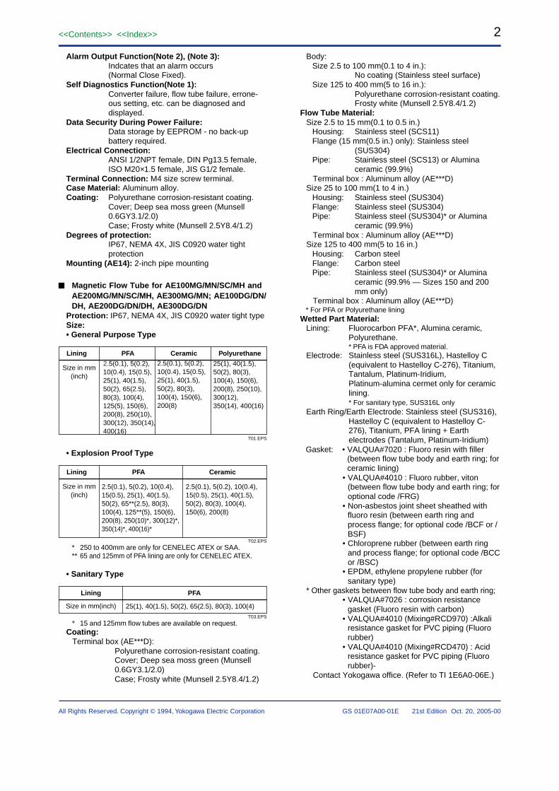
Alarm Output Function(Note 2), (Note 3):Indcates that an alarm occurs(Normal Close Fixed).
Self Diagnostics Function(Note 1):Converter failure, flow tube failure, errone-ous setting, etc. can be diagnosed anddisplayed.
Data Security During Power Failure:Data storage by EEPROM - no back-upbattery required.
Electrical Connection:ANSI 1/2NPT female, DIN Pg13.5 female,ISO M20×1.5 female, JIS G1/2 female.
Terminal Connection: M4 size screw terminal.Case Material: Aluminum alloy.Coating: Polyurethane corrosion-resistant coating.
Cover; Deep sea moss green (Munsell0.6GY3.1/2.0)Case; Frosty white (Munsell 2.5Y8.4/1.2)
Degrees of protection:IP67, NEMA 4X, JIS C0920 water tightprotection
Mounting (AE14): 2-inch pipe mounting
Magnetic Flow Tube for AE100MG/MN/SC/MH andAE200MG/MN/SC/MH, AE300MG/MN; AE100DG/DN/DH, AE200DG/DN/DH, AE300DG/DN
Protection: IP67, NEMA 4X, JIS C0920 water tight typeSize:• General Purpose Type
Size in mm(inch)
Lining PFA Ceramic Polyurethane
T01.EPS
2.5(0.1), 5(0.2), 10(0.4), 15(0.5), 25(1), 40(1.5), 50(2), 80(3), 100(4), 150(6), 200(8)
25(1), 40(1.5), 50(2), 80(3), 100(4), 150(6), 200(8), 250(10), 300(12), 350(14), 400(16)
2.5(0.1), 5(0.2), 10(0.4), 15(0.5), 25(1), 40(1.5), 50(2), 65(2.5), 80(3), 100(4), 125(5), 150(6),200(8), 250(10), 300(12), 350(14),400(16)
• Explosion Proof Type
Size in mm(inch)
Lining PFA Ceramic
T02.EPS
2.5(0.1), 5(0.2), 10(0.4), 15(0.5), 25(1), 40(1.5), 50(2), 65**(2.5), 80(3), 100(4), 125**(5), 150(6), 200(8), 250(10)*, 300(12)*, 350(14)*, 400(16)*
2.5(0.1), 5(0.2), 10(0.4), 15(0.5), 25(1), 40(1.5), 50(2), 80(3), 100(4), 150(6), 200(8)
* 250 to 400mm are only for CENELEC ATEX or SAA.** 65 and 125mm of PFA lining are only for CENELEC ATEX.
• Sanitary Type
Size in mm(inch)
Lining PFA
T03.EPS
25(1), 40(1.5), 50(2), 65(2.5), 80(3), 100(4)
* 15 and 125mm flow tubes are available on request.Coating:
Terminal box (AE***D):Polyurethane corrosion-resistant coating.Cover; Deep sea moss green (Munsell0.6GY3.1/2.0)Case; Frosty white (Munsell 2.5Y8.4/1.2)
Body:Size 2.5 to 100 mm(0.1 to 4 in.):
No coating (Stainless steel surface)Size 125 to 400 mm(5 to 16 in.):
Polyurethane corrosion-resistant coating.Frosty white (Munsell 2.5Y8.4/1.2)
Flow Tube Material:Size 2.5 to 15 mm(0.1 to 0.5 in.)
Housing: Stainless steel (SCS11)Flange (15 mm(0.5 in.) only): Stainless steel
(SUS304)Pipe: Stainless steel (SCS13) or Alumina
ceramic (99.9%) Terminal box : Aluminum alloy (AE***D)Size 25 to 100 mm(1 to 4 in.)
Housing: Stainless steel (SUS304)Flange: Stainless steel (SUS304)Pipe: Stainless steel (SUS304)* or Alumina
ceramic (99.9%) Terminal box : Aluminum alloy (AE***D)Size 125 to 400 mm(5 to 16 in.)
Housing: Carbon steelFlange: Carbon steelPipe: Stainless steel (SUS304)* or Alumina
ceramic (99.9% — Sizes 150 and 200mm only)
Terminal box : Aluminum alloy (AE***D)* For PFA or Polyurethane lining
Wetted Part Material:Lining: Fluorocarbon PFA*, Alumina ceramic,
Polyurethane.* PFA is FDA approved material.
Electrode: Stainless steel (SUS316L), Hastelloy C(equivalent to Hastelloy C-276), Titanium,Tantalum, Platinum-Iridium,Platinum-alumina cermet only for ceramiclining.* For sanitary type, SUS316L only
Earth Ring/Earth Electrode: Stainless steel (SUS316),Hastelloy C (equivalent to Hastelloy C-276), Titanium, PFA lining + Earthelectrodes (Tantalum, Platinum-Iridium)
Gasket: • VALQUA#7020 : Fluoro resin with filler(between flow tube body and earth ring; forceramic lining)
• VALQUA#4010 : Fluoro rubber, viton(between flow tube body and earth ring; foroptional code /FRG)
• Non-asbestos joint sheet sheathed withfluoro resin (between earth ring andprocess flange; for optional code /BCF or /BSF)
• Chloroprene rubber (between earth ringand process flange; for optional code /BCCor /BSC)
• EPDM, ethylene propylene rubber (forsanitary type)
* Other gaskets between flow tube body and earth ring;• VALQUA#7026 : corrosion resistance
gasket (Fluoro resin with carbon)• VALQUA#4010 (Mixing#RCD970) :Alkali
resistance gasket for PVC piping (Fluororubber)
• VALQUA#4010 (Mixing#RCD470) : Acidresistance gasket for PVC piping (Fluororubber)-
Contact Yokogawa office. (Refer to TI 1E6A0-06E.)
3<<Contents>> <<Index>>
All Rights Reserved. Copyright © 1994, Yokogawa Electric Corporation GS 01E07A00-01E 21st Edition Oct. 20, 2005-00
Union Joint: Stainless steel (SUS316L) for ceramiclining size 10 mm(0.4in.) or less.*
* Contact YOKOGAWA office if PVC Union Joints arerequired.
Ferrule (for sanitary type): SCS13Electrode Construction:
• General Purpose/Ex-proof TypePFA, Polyurethane Lining: External insertion type.Ceramic Lining: Integral type.
• Sanitary TypeInternal insertion type* Only PFA lining is available for sanitary type.
Grounding:100Ω or less* In case of TIIS(JIS) Flameproof type, JIS Class C
(10Ω or less) or JIS Class A(10Ω or less)Electrical Connection(AE***D):
ANSI 1/2NPT female, DIN Pg13.5 female,ISO M20×1.5 female, JIS G1/2 female.
Note: Hastelloy is a registered trademark of HaynesInternational Inc.
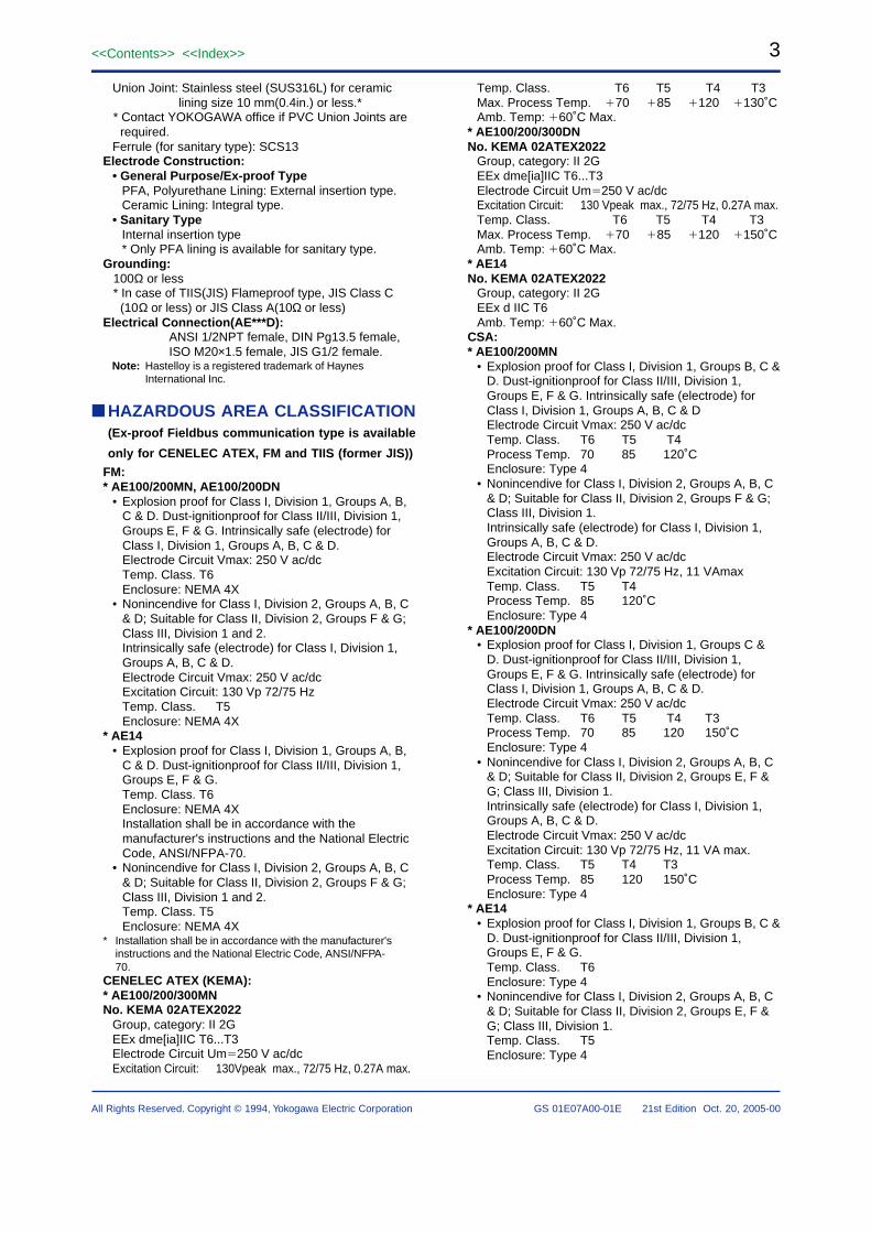
HAZARDOUS AREA CLASSIFICATION(Ex-proof Fieldbus communication type is available
only for CENELEC ATEX, FM and TIIS (former JIS))
FM:* AE100/200MN, AE100/200DN
• Explosion proof for Class I, Division 1, Groups A, B,C & D. Dust-ignitionproof for Class II/III, Division 1,Groups E, F & G. Intrinsically safe (electrode) forClass I, Division 1, Groups A, B, C & D.Electrode Circuit Vmax: 250 V ac/dcTemp. Class. T6Enclosure: NEMA 4X
• Nonincendive for Class I, Division 2, Groups A, B, C& D; Suitable for Class II, Division 2, Groups F & G;Class III, Division 1 and 2.Intrinsically safe (electrode) for Class I, Division 1,Groups A, B, C & D.Electrode Circuit Vmax: 250 V ac/dcExcitation Circuit: 130 Vp 72/75 HzTemp. Class. T5Enclosure: NEMA 4X
* AE14• Explosion proof for Class I, Division 1, Groups A, B,
C & D. Dust-ignitionproof for Class II/III, Division 1,Groups E, F & G.Temp. Class. T6Enclosure: NEMA 4XInstallation shall be in accordance with themanufacturer's instructions and the National ElectricCode, ANSI/NFPA-70.
• Nonincendive for Class I, Division 2, Groups A, B, C& D; Suitable for Class II, Division 2, Groups F & G;Class III, Division 1 and 2.Temp. Class. T5Enclosure: NEMA 4X
* Installation shall be in accordance with the manufacturer'sinstructions and the National Electric Code, ANSI/NFPA-70.
CENELEC ATEX (KEMA):* AE100/200/300MNNo. KEMA 02ATEX2022
Group, category: II 2GEEx dme[ia]IIC T6...T3Electrode Circuit Um250 V ac/dcExcitation Circuit: 130Vpeak max., 72/75 Hz, 0.27A max.
Temp. Class. T6 T5 T4 T3Max. Process Temp. 70 85 120 130˚CAmb. Temp: 60˚C Max.
* AE100/200/300DNNo. KEMA 02ATEX2022
Group, category: II 2GEEx dme[ia]IIC T6...T3Electrode Circuit Um250 V ac/dcExcitation Circuit: 130 Vpeak max., 72/75 Hz, 0.27A max.Temp. Class. T6 T5 T4 T3Max. Process Temp. 70 85 120 150˚CAmb. Temp: 60˚C Max.
* AE14No. KEMA 02ATEX2022
Group, category: II 2GEEx d IIC T6Amb. Temp: 60˚C Max.
CSA:* AE100/200MN
• Explosion proof for Class I, Division 1, Groups B, C &D. Dust-ignitionproof for Class II/III, Division 1,Groups E, F & G. Intrinsically safe (electrode) forClass I, Division 1, Groups A, B, C & DElectrode Circuit Vmax: 250 V ac/dcTemp. Class. T6 T5 T4Process Temp. 70 85 120˚CEnclosure: Type 4
• Nonincendive for Class I, Division 2, Groups A, B, C& D; Suitable for Class II, Division 2, Groups F & G;Class III, Division 1.Intrinsically safe (electrode) for Class I, Division 1,Groups A, B, C & D.Electrode Circuit Vmax: 250 V ac/dcExcitation Circuit: 130 Vp 72/75 Hz, 11 VAmaxTemp. Class. T5 T4Process Temp. 85 120˚CEnclosure: Type 4
* AE100/200DN• Explosion proof for Class I, Division 1, Groups C &
D. Dust-ignitionproof for Class II/III, Division 1,Groups E, F & G. Intrinsically safe (electrode) forClass I, Division 1, Groups A, B, C & D.Electrode Circuit Vmax: 250 V ac/dcTemp. Class. T6 T5 T4 T3Process Temp. 70 85 120 150˚CEnclosure: Type 4
• Nonincendive for Class I, Division 2, Groups A, B, C& D; Suitable for Class II, Division 2, Groups E, F &G; Class III, Division 1.Intrinsically safe (electrode) for Class I, Division 1,Groups A, B, C & D.Electrode Circuit Vmax: 250 V ac/dcExcitation Circuit: 130 Vp 72/75 Hz, 11 VA max.Temp. Class. T5 T4 T3Process Temp. 85 120 150˚CEnclosure: Type 4
* AE14• Explosion proof for Class I, Division 1, Groups B, C &
D. Dust-ignitionproof for Class II/III, Division 1,Groups E, F & G.Temp. Class. T6Enclosure: Type 4
• Nonincendive for Class I, Division 2, Groups A, B, C& D; Suitable for Class II, Division 2, Groups E, F &G; Class III, Division 1.Temp. Class. T5Enclosure: Type 4
4<<Contents>> <<Index>>
GS 01E07A00-01E 21st Edition Oct. 20, 2005-00All Rights Reserved. Copyright © 1994, Yokogawa Electric Corporation
SAA:* AE100/200/300MN
SA Certificate No.: AUS Ex 3210XType of Protection: Ex dm[ia]IIC T6 IP67Electrode Circuit Um: 250 V ac/dcExcitation Circuit: 130 Vp 72/75 HzTemp. Class. T6 T5 T4Process Temp. 70 85 120˚C
* AE100/200/300DNSA Certificate No.: AUS Ex 3210XType of Protection: Ex dm[ia]IIC T6 IP67Electrode Circuit Um: 250 V ac/dcExcitation Circuit: 130 Vp 72/75 HzTemp. Class. T6 T5 T4 T3Process Temp. 70 85 120 150˚C
* AE14SA Certificate No.: AUS Ex 3210XType of Protection: Ex d IIC T6 IP67
TIIS (former JIS):* AE100/200SC• Construction : Exde[ia] II CT4X
: Converter, Terminal box; Explosion proof Flow Tube ; Increased Safety Signal Circuit; Intrinsically Safety (ia): Ignition and Explosion Class of gas or vapour ; II CT4X
• Ambient Temperature : -10 to 60˚C*• Fluid Temperature : 120˚C or less• Grounding : JIS Class C(10Ω or less) or JIS Class A
(10Ω or less)* In case the ambient temperature exceeds 50˚C, use
heat-resistant cables with maximum allowabletemperature of 70˚C or above.
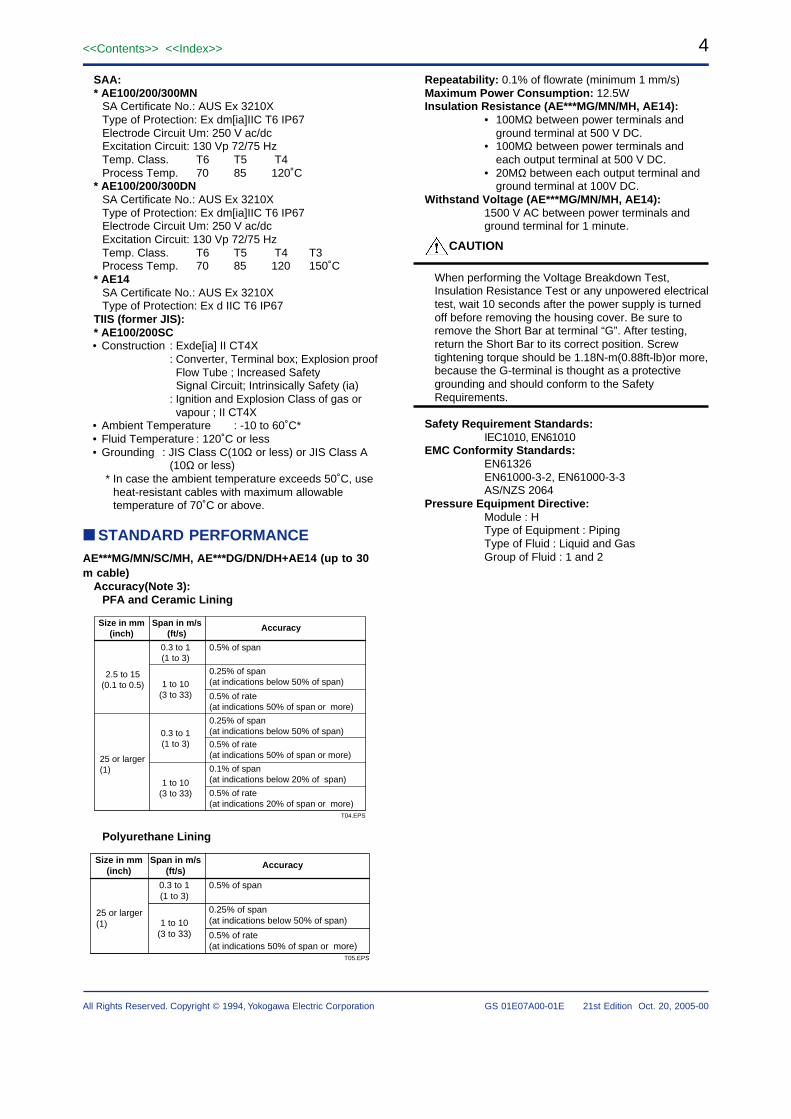
STANDARD PERFORMANCEAE***MG/MN/SC/MH, AE***DG/DN/DH+AE14 (up to 30m cable)
Accuracy(Note 3):PFA and Ceramic Lining
Size in mm(inch)
Span in m/s(ft/s)
Accuracy
2.5 to 15(0.1 to 0.5)
0.3 to 1(1 to 3)
1 to 10(3 to 33)
0.3 to 1(1 to 3)
1 to 10(3 to 33)
25 or larger(1)
0.5% of span
0.25% of span(at indications below 50% of span)
0.5% of rate (at indications 50% of span or more)
0.25% of span(at indications below 50% of span)
0.5% of rate (at indications 50% of span or more)
0.1% of span(at indications below 20% of span)
0.5% of rate (at indications 20% of span or more)
T04.EPS
Polyurethane Lining
Size in mm(inch)
Span in m/s(ft/s)
Accuracy
0.3 to 1(1 to 3)
1 to 10(3 to 33)
25 or larger(1)
0.5% of span
0.25% of span(at indications below 50% of span)
0.5% of rate (at indications 50% of span or more)
T05.EPS
Repeatability: 0.1% of flowrate (minimum 1 mm/s)Maximum Power Consumption: 12.5WInsulation Resistance (AE***MG/MN/MH, AE14):
• 100MΩ between power terminals andground terminal at 500 V DC.
• 100MΩ between power terminals andeach output terminal at 500 V DC.
• 20MΩ between each output terminal andground terminal at 100V DC.
Withstand Voltage (AE***MG/MN/MH, AE14):1500 V AC between power terminals andground terminal for 1 minute.
CAUTION
When performing the Voltage Breakdown Test,Insulation Resistance Test or any unpowered electricaltest, wait 10 seconds after the power supply is turnedoff before removing the housing cover. Be sure toremove the Short Bar at terminal “G”. After testing,return the Short Bar to its correct position. Screwtightening torque should be 1.18N-m(0.88ft-lb)or more,because the G-terminal is thought as a protectivegrounding and should conform to the SafetyRequirements.
Safety Requirement Standards:IEC1010, EN61010
EMC Conformity Standards:EN61326EN61000-3-2, EN61000-3-3AS/NZS 2064
Pressure Equipment Directive:Module : HType of Equipment : PipingType of Fluid : Liquid and GasGroup of Fluid : 1 and 2
5<<Contents>> <<Index>>
All Rights Reserved. Copyright © 1994, Yokogawa Electric Corporation GS 01E07A00-01E 21st Edition Oct. 20, 2005-00
General Purpose / Explosion Proof
***
***
***
***
***
T22.EPS
AE102MG/MN/SCAE102DG/DN
AE105MG/MN/SCAE105DG/DN
AE110MG/MN/SCAE110DG/DN
AE115MG/MN/SCAE115DG/DN
AE202MG/MN/SCAE202DG/DNAE204MG/MN/SCAE204DG/DN
AE205MG/MN/SCAE205DG/DN
AE206MG/MN/SCAE206DG/DN
AE208MG/MN/SCAE208DG/DN
AE210MG/MN/SCAE210DG/DN
AE212MG/MN/SCAE212DG/DN
AE215MG/MN/SCAE215DG/DN
AE220MG/MN/SCAE220DG/DN
AE325MG/MN/SCAE325DG/DN
AE330MG/MN/SCAE330DG/DN
AE335MG/MN/SCAE335DG/DN
AE340MG/MN/SCAE340DG/DN
DN(mm)*
2.5
5
10
15
25
40
50
65
80
100
125
150
200
250
300
350
400
PS(MPa)*
4
4
4
4
4
4
4
2
2
2
2
2
2
2
2
1
1
PS·DN(MPa·mm)
10
20
40
60
100
160
200
130
160
200
250
300
400
500
600
700
800
CATEGORY**
Article 3,paragraph 3
Article 3,paragraph 3
Article 3,paragraph 3
Article 3,paragraph 3
Article 3,paragraph 3
II
II
II
II
II
II
II
III
III
III
II
III
MODEL
Sanitary
***
T22.EPS
AE202MHAE202DH
AE204MHAE204DH
AE205MHAE205DH
AE206MHAE206DH
AE208MHAE208DH
AE210MHAE210DH
DN(mm)*
25
40
50
65
80
100
PS(MPa)*
1
1
1
1
1
1
PS·DN(MPa·mm)
25
40
50
65
80
100
CATEGORY**
Article 3,paragraph 3
I
I
I
I
I
MODEL
* PS: Maximum allowable pressure for Flow TubeDN: Nominal size
** Referred to Table 6 covered by ANNEX II of EC Directiveon Pressure Equipment Directive 97/23/EC)
*** AE102MG/MN/SC/AE102DG/DN to AE202MG/MN/SC/AE202DG/DN, and AE202MH/AE202DH are notattached CE mark of PED because they do not comeunder CE marking of PED.
NORMAL OPERATING CONDITIONSAmbient Temperature: -10 to 60˚C (14 to 140˚F)Ambient Humidity: 5 to 95%RH (no condensation)Power Supply Voltage: -A1; Range 80 to 264 V AC, 47
to 63Hz/100 to 130 VDC, -D1; Range 20.4 to 28.8 V DC(except /FB)
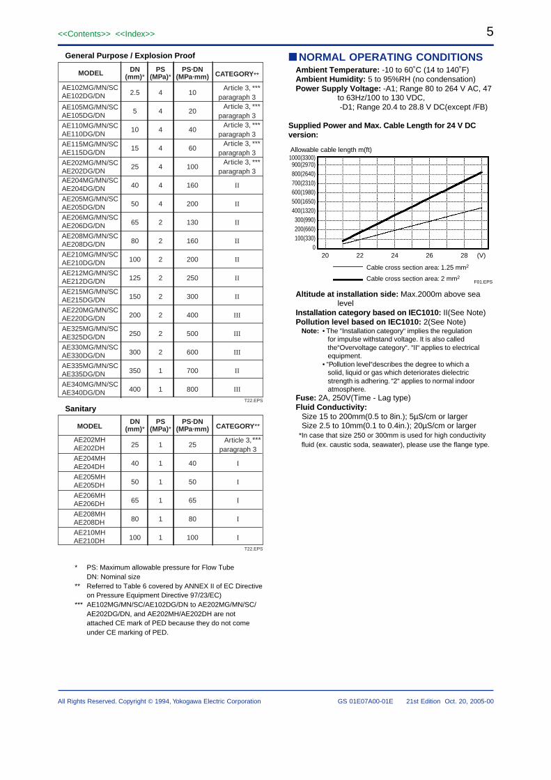
Supplied Power and Max. Cable Length for 24 V DCversion:
Allowable cable length m(ft)1000(3300)900(2970)800(2640)700(2310)600(1980)500(1650)400(1320)300(990)200(660)100(330)
020 22 24 26 28 (V)
Cable cross section area: 1.25 mm2
Cable cross section area: 2 mm2F01.EPS
Altitude at installation side: Max.2000m above sealevel
Installation category based on IEC1010: II(See Note)Pollution level based on IEC1010: 2(See Note)
Note: • The “Installation category“ implies the regulationfor impulse withstand voltage. It is also calledthe“Overvoltage category“. “II“ applies to electricalequipment.
• “Pollution level“describes the degree to which asolid, liquid or gas which deteriorates dielectricstrength is adhering. “2“ applies to normal indooratmosphere.
Fuse: 2A, 250V(Time - Lag type)Fluid Conductivity:
Size 15 to 200mm(0.5 to 8in.); 5µS/cm or largerSize 2.5 to 10mm(0.1 to 0.4in.); 20µS/cm or larger
*In case that size 250 or 300mm is used for high conductivityfluid (ex. caustic soda, seawater), please use the flange type.
6<<Contents>> <<Index>>
GS 01E07A00-01E 21st Edition Oct. 20, 2005-00All Rights Reserved. Copyright © 1994, Yokogawa Electric Corporation
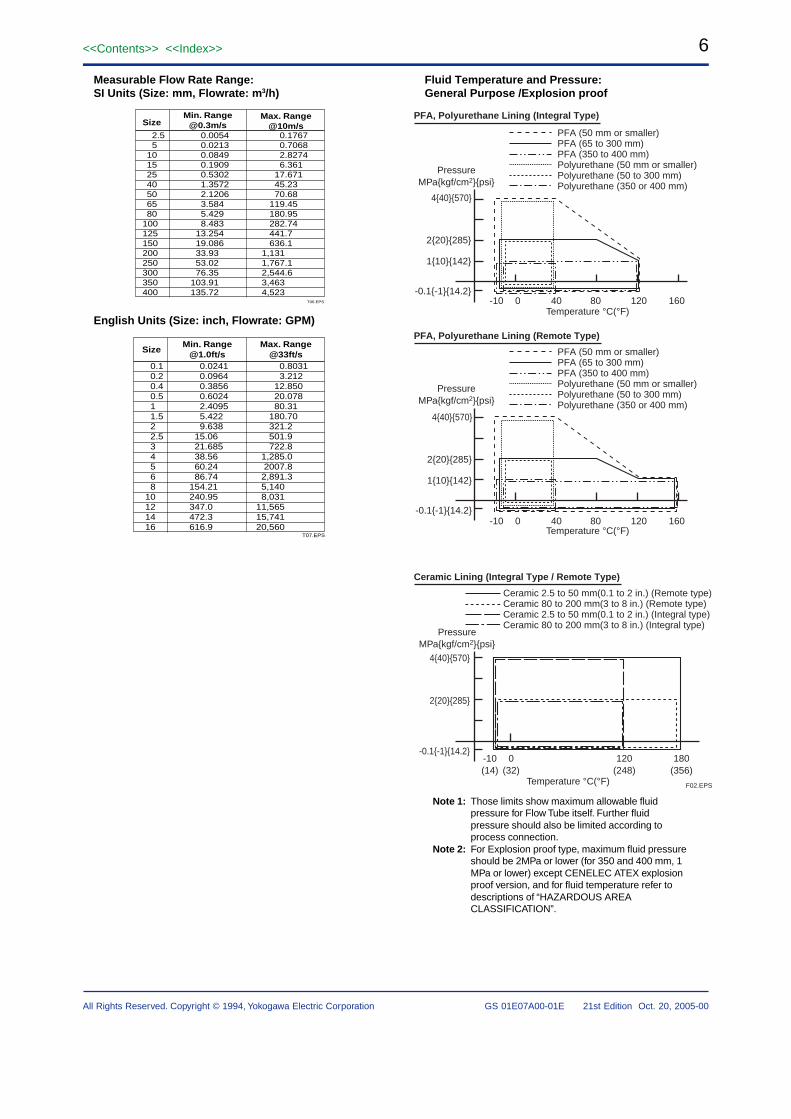
Fluid Temperature and Pressure:General Purpose /Explosion proof
PressureMPakgf/cm2psi
PressureMPakgf/cm2psi
440570
220285
-0.1-114.2
Ceramic 2.5 to 50 mm(0.1 to 2 in.) (Remote type)Ceramic 80 to 200 mm(3 to 8 in.) (Remote type)Ceramic 2.5 to 50 mm(0.1 to 2 in.) (Integral type)Ceramic 80 to 200 mm(3 to 8 in.) (Integral type)
-10(14)
0(32)
180(356)
Temperature °C(°F)
Temperature °C(°F)
Temperature °C(°F)
F02.EPS
120(248)
PFA, Polyurethane Lining (Remote Type)
Ceramic Lining (Integral Type / Remote Type)
PressureMPakgf/cm2psi
-10 0 40 80 120 160
PFA (50 mm or smaller)PFA (65 to 300 mm)PFA (350 to 400 mm)Polyurethane (50 mm or smaller)Polyurethane (50 to 300 mm)Polyurethane (350 or 400 mm)
PFA, Polyurethane Lining (Integral Type)
PFA (50 mm or smaller)PFA (65 to 300 mm)PFA (350 to 400 mm)Polyurethane (50 mm or smaller)Polyurethane (50 to 300 mm)Polyurethane (350 or 400 mm)
-10 0 40 80 120 160
220285
110142
-0.1-114.2
440570
220285
110142
-0.1-114.2
440570
Note 1: Those limits show maximum allowable fluidpressure for Flow Tube itself. Further fluidpressure should also be limited according toprocess connection.
Note 2: For Explosion proof type, maximum fluid pressureshould be 2MPa or lower (for 350 and 400 mm, 1MPa or lower) except CENELEC ATEX explosionproof version, and for fluid temperature refer todescriptions of “HAZARDOUS AREACLASSIFICATION”.
Measurable Flow Rate Range:SI Units (Size: mm, Flowrate: m3/h)
SizeMin. Range
@0.3m/sMax. Range
@10m/s2.5 0.0054 0.17675 0.0213 0.7068
10 0.0849 2.827415 0.1909 6.36125 0.5302 17.67140 1.3572 45.2350 2.1206 70.6865 3.584 119.4580 5.429 180.95
100 8.483 282.74125 13.254 441.7150 19.086 636.1200 33.93 1,131250 53.02 1,767.1300 76.35 2,544.6350 103.91 3,463400 135.72 4,523
T06.EPS
English Units (Size: inch, Flowrate: GPM)
SizeMin. Range
@1.0ft/sMax. Range
@33ft/s0.1 0.0241 0.80310.2 0.0964 3.2120.4 0.3856 12.850 0.5 0.6024 20.0781 2.4095 80.311.5 5.422 180.70 2 9.638 321.22.5 15.06 501.93 21.685 722.84 38.56 1,285.05 60.24 2007.86 86.74 2,891.3 8 154.21 5,140
10 240.95 8,03112 347.0 11,56514 472.3 15,74116 616.9 20,560
T07.EPS
7<<Contents>> <<Index>>
All Rights Reserved. Copyright © 1994, Yokogawa Electric Corporation GS 01E07A00-01E 21st Edition Oct. 20, 2005-00
PressureMPakgf/cm2psi
11014.3
-0.1-114.2-10(14)
0(32)
160(320)
Temperature °C(°F) F02-2.EPS
120(248)
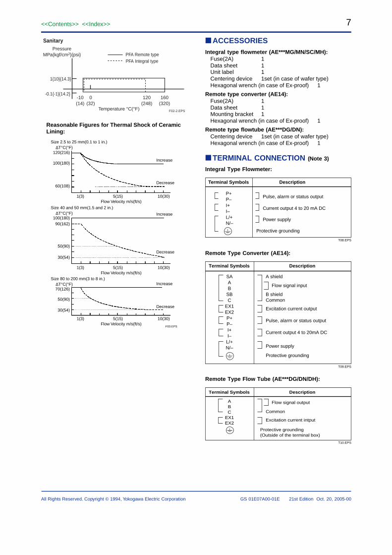
Sanitary
PFA Remote typePFA Integral type
Reasonable Figures for Thermal Shock of CeramicLining:
F03.EPS
Size 2.5 to 25 mm(0.1 to 1 in.)∆T°C(°F)
120(216)
100(180)
60(108)
Increase
Decrease
1(3) 5(15) 10(30)Flow Velocity m/s(ft/s)
Size 40 and 50 mm(1.5 and 2 in.)∆T°C(°F)
90(162)
50(90)
100(180)
30(54)
Increase
Decrease
1(3) 5(15) 10(30)Flow Velocity m/s(ft/s)
Size 80 to 200 mm(3 to 8 in.)∆T°C(°F)
50(90)
70(126)
30(54)
Increase
Decrease
1(3) 5(15) 10(30)Flow Velocity m/s(ft/s)
ACCESSORIESIntegral type flowmeter (AE***MG/MN/SC/MH):
Fuse(2A) 1Data sheet 1Unit label 1Centering device 1set (in case of wafer type)Hexagonal wrench (in case of Ex-proof) 1
Remote type converter (AE14):Fuse(2A) 1Data sheet 1Mounting bracket 1Hexagonal wrench (in case of Ex-proof) 1
Remote type flowtube (AE***DG/DN):Centering device 1set (in case of wafer type)Hexagonal wrench (in case of Ex-proof) 1
TERMINAL CONNECTION (Note 3)
Integral Type Flowmeter:
Terminal Symbols Description
P+P–I+I–L/+N/–
Current output 4 to 20 mA DC
Power supply
Protective grounding
Pulse, alarm or status output
T08.EPS
Remote Type Converter (AE14):
Terminal Symbols Description
SAAB
SBC
EX1EX2P+P–I+I–
L/+N/–
A shield
Flow signal input
B shieldCommon
Excitation current output
Pulse, alarm or status output
Current output 4 to 20mA DC
Power supply
T09.EPS
Protective grounding
Remote Type Flow Tube (AE***DG/DN/DH):
ABC
EX1EX2
T10.EPS
Flow signal output
Common
Excitation current intput
Terminal Symbols Description
Protective grounding (Outside of the terminal box)
8<<Contents>> <<Index>>
GS 01E07A00-01E 21st Edition Oct. 20, 2005-00All Rights Reserved. Copyright © 1994, Yokogawa Electric Corporation
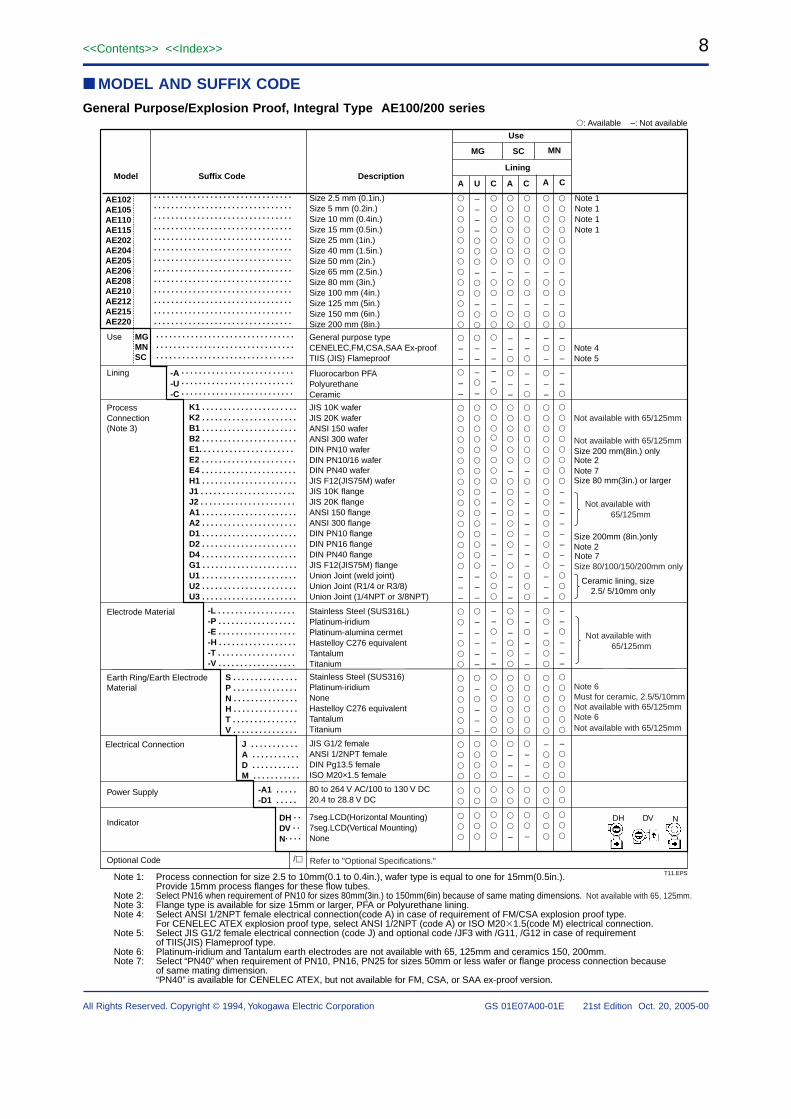
MODEL AND SUFFIX CODE
General Purpose/Explosion Proof, Integral Type AE100/200 series
AE102AE105AE110AE115AE202AE204AE205AE206AE208AE210AE212AE215AE220
Lining
A U C A C
Size 80 mm(3in.) or larger
Note 1Note 1Note 1Note 1
Size 200mm (8in.)onlyNote 2
––
––
–––
–
––––
–
–
––
–
–
–––
–––––
–
–––
–
–
––
––
––––––––
––
–––
–
–
–
–
––
–––
–
–
–
–
–
–
––
––––––––
––
–––
–
Suffix CodeModel Description
Use
MG SC
: Available –: Not available
Use MGMNSC
Lining
Process Connection(Note 3)
Electrode Material
Earth Ring/Earth Electrode Material
Electrical Connection
Power Supply
Indicator
Optional CodeT11.EPS
. . . . . . . . . . . . . . . . . . . . . . . . . . . . . . . .
. . . . . . . . . . . . . . . . . . . . . . . . . . . . . . . .
. . . . . . . . . . . . . . . . . . . . . . . . . . . . . . . .
. . . . . . . . . . . . . . . . . . . . . . . . . . . . . . . .
. . . . . . . . . . . . . . . . . . . . . . . . . . . . . . . .
. . . . . . . . . . . . . . . . . . . . . . . . . . . . . . . .
. . . . . . . . . . . . . . . . . . . . . . . . . . . . . . . .
. . . . . . . . . . . . . . . . . . . . . . . . . . . . . . . .
. . . . . . . . . . . . . . . . . . . . . . . . . . . . . . . .
. . . . . . . . . . . . . . . . . . . . . . . . . . . . . . . .
. . . . . . . . . . . . . . . . . . . . . . . . . . . . . . . .
. . . . . . . . . . . . . . . . . . . . . . . . . . . . . . . .
. . . . . . . . . . . . . . . . . . . . . . . . . . . . . . . .
Ceramic lining, size 2.5/ 5/10mm only
Note 7Note 2
DH DV N
MN
A C
–
–
––
––
–
–
–––
–
–––
–
–
–
––
––
–
––––––––
––
–––
–––
–
Note 4Note 5
Note 1: Process connection for size 2.5 to 10mm(0.1 to 0.4in.), wafer type is equal to one for 15mm(0.5in.). Provide 15mm process flanges for these flow tubes.
Note 2: Select PN16 when requirement of PN10 for sizes 80mm(3in.) to 150mm(6in) because of same mating dimensions. Not available with 65, 125mm.Note 3: Flange type is available for size 15mm or larger, PFA or Polyurethane lining.Note 4: Select ANSI 1/2NPT female electrical connection(code A) in case of requirement of FM/CSA explosion proof type.
For CENELEC ATEX explosion proof type, select ANSI 1/2NPT (code A) or ISO M201.5(code M) electrical connection.Note 5: Select JIS G1/2 female electrical connection (code J) and optional code /JF3 with /G11, /G12 in case of requirement
of TIIS(JIS) Flameproof type.Note 6: Platinum-iridium and Tantalum earth electrodes are not available with 65, 125mm and ceramics 150, 200mm.Note 7: Select “PN40” when requirement of PN10, PN16, PN25 for sizes 50mm or less wafer or flange process connection because
of same mating dimension.“PN40” is available for CENELEC ATEX, but not available for FM, CSA, or SAA ex-proof version.
Refer to "Optional Specifications."
Not available with 65/125mm
Not available with 65/125mmSize 200 mm(8in.) only
Not available with 65/125mm
Not available with 65/125mm
Note 6
Note 6
Must for ceramic, 2.5/5/10mm
Size 80/100/150/200mm only
Not available with 65/125mm
Not available with 65/125mm
Note 7
. . . . . . . . . . . . . . . . . . . . . . . . . . . . . . . .
. . . . . . . . . . . . . . . . . . . . . . . . . . . . . . . .
. . . . . . . . . . . . . . . . . . . . . . . . . . . . . . . .
-A . . . . . . . . . . . . . . . . . . . . . . . . . .
-U . . . . . . . . . . . . . . . . . . . . . . . . . .
-C . . . . . . . . . . . . . . . . . . . . . . . . . .
K1 . . . . . . . . . . . . . . . . . . . . . .K2 . . . . . . . . . . . . . . . . . . . . . .B1 . . . . . . . . . . . . . . . . . . . . . .B2 . . . . . . . . . . . . . . . . . . . . . .E1. . . . . . . . . . . . . . . . . . . . . .E2 . . . . . . . . . . . . . . . . . . . . . .E4 . . . . . . . . . . . . . . . . . . . . . .H1 . . . . . . . . . . . . . . . . . . . . . .J1 . . . . . . . . . . . . . . . . . . . . . .J2 . . . . . . . . . . . . . . . . . . . . . .A1 . . . . . . . . . . . . . . . . . . . . . .A2 . . . . . . . . . . . . . . . . . . . . . .D1 . . . . . . . . . . . . . . . . . . . . . .D2 . . . . . . . . . . . . . . . . . . . . . .D4 . . . . . . . . . . . . . . . . . . . . . .G1 . . . . . . . . . . . . . . . . . . . . . .U1 . . . . . . . . . . . . . . . . . . . . . .U2 . . . . . . . . . . . . . . . . . . . . . .U3 . . . . . . . . . . . . . . . . . . . . . .
-L . . . . . . . . . . . . . . . . . .-P . . . . . . . . . . . . . . . . . .-E . . . . . . . . . . . . . . . . . .-H . . . . . . . . . . . . . . . . . .-T . . . . . . . . . . . . . . . . . .-V . . . . . . . . . . . . . . . . . .
S . . . . . . . . . . . . . . .P . . . . . . . . . . . . . . .N . . . . . . . . . . . . . . .H . . . . . . . . . . . . . . .T . . . . . . . . . . . . . . .V . . . . . . . . . . . . . . .
J . . . . . . . . . . .A . . . . . . . . . . .D . . . . . . . . . . .M . . . . . . . . . . .
-A1 . . . . .-D1 . . . . .
DH . .
DV . .
N. . . .
/
Size 2.5 mm (0.1in.)Size 5 mm (0.2in.)Size 10 mm (0.4in.)Size 15 mm (0.5in.)Size 25 mm (1in.)Size 40 mm (1.5in.)Size 50 mm (2in.)Size 65 mm (2.5in.)Size 80 mm (3in.)Size 100 mm (4in.)Size 125 mm (5in.)Size 150 mm (6in.)Size 200 mm (8in.)
General purpose typeCENELEC,FM,CSA,SAA Ex-proofTIIS (JIS) Flameproof
Fluorocarbon PFAPolyurethane Ceramic
JIS 10K waferJIS 20K waferANSI 150 waferANSI 300 waferDIN PN10 waferDIN PN10/16 waferDIN PN40 waferJIS F12(JIS75M) waferJIS 10K flangeJIS 20K flangeANSI 150 flangeANSI 300 flangeDIN PN10 flangeDIN PN16 flangeDIN PN40 flangeJIS F12(JIS75M) flangeUnion Joint (weld joint)Union Joint (R1/4 or R3/8)Union Joint (1/4NPT or 3/8NPT)
Stainless Steel (SUS316L)Platinum-iridiumPlatinum-alumina cermetHastelloy C276 equivalentTantalumTitanium
Stainless Steel (SUS316)Platinum-iridiumNoneHastelloy C276 equivalentTantalumTitanium
JIS G1/2 femaleANSI 1/2NPT femaleDIN Pg13.5 femaleISO M20×1.5 female
80 to 264 V AC/100 to 130 V DC20.4 to 28.8 V DC
7seg.LCD(Horizontal Mounting)7seg.LCD(Vertical Mounting)None
9<<Contents>> <<Index>>
All Rights Reserved. Copyright © 1994, Yokogawa Electric Corporation GS 01E07A00-01E 21st Edition Oct. 20, 2005-00
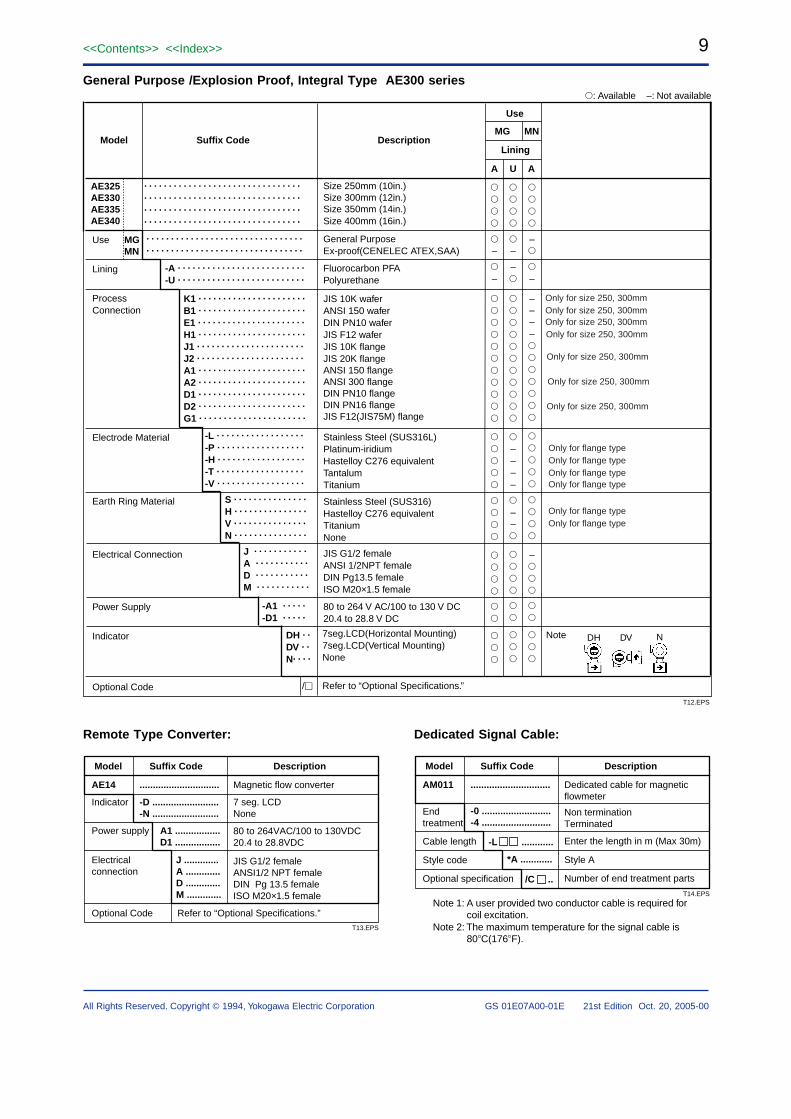
General Purpose /Explosion Proof, Integral Type AE300 series
AE325AE330AE335AE340
. . . . . . . . . . . . . . . . . . . . . . . . . . . . . . . .
. . . . . . . . . . . . . . . . . . . . . . . . . . . . . . . .
-A . . . . . . . . . . . . . . . . . . . . . . . . . .
-U . . . . . . . . . . . . . . . . . . . . . . . . . .
K1 . . . . . . . . . . . . . . . . . . . . . .
B1 . . . . . . . . . . . . . . . . . . . . . .
E1 . . . . . . . . . . . . . . . . . . . . . .
H1 . . . . . . . . . . . . . . . . . . . . . .
J1 . . . . . . . . . . . . . . . . . . . . . .
J2 . . . . . . . . . . . . . . . . . . . . . .
A1 . . . . . . . . . . . . . . . . . . . . . .
A2 . . . . . . . . . . . . . . . . . . . . . .
D1 . . . . . . . . . . . . . . . . . . . . . .
D2 . . . . . . . . . . . . . . . . . . . . . .
G1 . . . . . . . . . . . . . . . . . . . . . .
-L . . . . . . . . . . . . . . . . . .
-P . . . . . . . . . . . . . . . . . .
-H . . . . . . . . . . . . . . . . . .
-T . . . . . . . . . . . . . . . . . .
-V . . . . . . . . . . . . . . . . . .
S . . . . . . . . . . . . . . .
H . . . . . . . . . . . . . . .
V . . . . . . . . . . . . . . .
N . . . . . . . . . . . . . . .
J . . . . . . . . . . .
A . . . . . . . . . . .
D . . . . . . . . . . .
M . . . . . . . . . . .
-A1 . . . . .
-D1 . . . . .
DH . .
DV . .
N. . . .
/
Size 250mm (10in.)Size 300mm (12in.)Size 350mm (14in.)Size 400mm (16in.)
General PurposeEx-proof(CENELEC ATEX,SAA)
Fluorocarbon PFAPolyurethane
JIS 10K waferANSI 150 waferDIN PN10 waferJIS F12 waferJIS 10K flangeJIS 20K flangeANSI 150 flangeANSI 300 flangeDIN PN10 flangeDIN PN16 flangeJIS F12(JIS75M) flange
Stainless Steel (SUS316L)Platinum-iridiumHastelloy C276 equivalentTantalumTitanium
Stainless Steel (SUS316)Hastelloy C276 equivalentTitaniumNone
JIS G1/2 femaleANSI 1/2NPT femaleDIN Pg13.5 femaleISO M20×1.5 female
80 to 264 V AC/100 to 130 V DC20.4 to 28.8 V DC
Lining
A U A
–
–
–
–
––––
––
–
–
––––
–
Suffix CodeModel Description
Use
MG MN
: Available –: Not available
Use MGMN
Lining
Process Connection
Electrode Material
Earth Ring Material
Electrical Connection
Power Supply
Indicator
Optional Code
T12.EPS
. . . . . . . . . . . . . . . . . . . . . . . . . . . . . . . .
. . . . . . . . . . . . . . . . . . . . . . . . . . . . . . . .
. . . . . . . . . . . . . . . . . . . . . . . . . . . . . . . .
. . . . . . . . . . . . . . . . . . . . . . . . . . . . . . . .
Refer to “Optional Specifications.”
7seg.LCD(Horizontal Mounting)7seg.LCD(Vertical Mounting)None
Note DH DV N
Only for size 250, 300mmOnly for size 250, 300mm
Only for size 250, 300mmOnly for size 250, 300mm
Only for size 250, 300mm
Only for size 250, 300mm
Only for size 250, 300mm
Only for flange type
Only for flange type
Only for flange typeOnly for flange type
Only for flange typeOnly for flange type
Remote Type Converter:
Model Suffix Code Description
AE14 ..............................
-D .........................-N .........................
Magnetic flow converter
7 seg. LCD None
80 to 264VAC/100 to 130VDC20.4 to 28.8VDC
JIS G1/2 femaleANSI1/2 NPT femaleDIN Pg 13.5 femaleISO M20×1.5 female
A1 .................D1 .................
J .............A .............D .............M .............
Indicator
Power supply
Electricalconnection
Optional Code Refer to “Optional Specifications.”T13.EPS
Dedicated Signal Cable:
Model Suffix Code Description
AM011 ..............................
-0 ..........................-4 ..........................
Dedicated cable for magneticflowmeter
Non terminationTerminated
Enter the length in m (Max 30m)
Style A
Number of end treatment parts
-L ............
*A ............
/C ..
Endtreatment
Cable length
Style code
Optional specification
T14.EPS
Note 1: A user provided two conductor cable is required forcoil excitation.
Note 2: The maximum temperature for the signal cable is80C(176F).
10<<Contents>> <<Index>>
GS 01E07A00-01E 21st Edition Oct. 20, 2005-00All Rights Reserved. Copyright © 1994, Yokogawa Electric Corporation
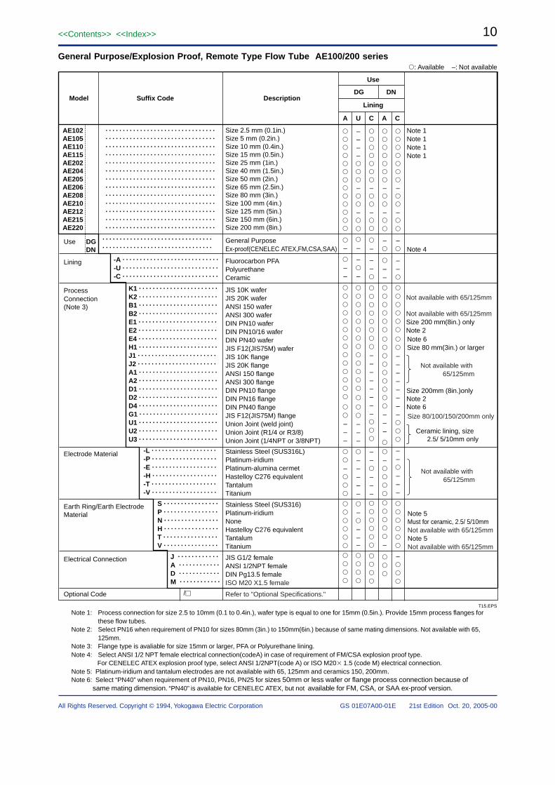
General Purpose/Explosion Proof, Remote Type Flow Tube AE100/200 series
AE102AE105AE110AE115AE202AE204AE205AE206AE208AE210AE212AE215AE220
. . . . . . . . . . . . . . . . . . . . . . . . . . . . . . . .
. . . . . . . . . . . . . . . . . . . . . . . . . . . . . . . .
-A . . . . . . . . . . . . . . . . . . . . . . . . . . . .
-U . . . . . . . . . . . . . . . . . . . . . . . . . . . .
-C . . . . . . . . . . . . . . . . . . . . . . . . . . . .
K1 . . . . . . . . . . . . . . . . . . . . . . .
K2 . . . . . . . . . . . . . . . . . . . . . . .
B1 . . . . . . . . . . . . . . . . . . . . . . .
B2 . . . . . . . . . . . . . . . . . . . . . . .
E1 . . . . . . . . . . . . . . . . . . . . . . .
E2 . . . . . . . . . . . . . . . . . . . . . . .
E4 . . . . . . . . . . . . . . . . . . . . . . .
H1 . . . . . . . . . . . . . . . . . . . . . . .
J1 . . . . . . . . . . . . . . . . . . . . . . .
J2 . . . . . . . . . . . . . . . . . . . . . . .
A1 . . . . . . . . . . . . . . . . . . . . . . .
A2 . . . . . . . . . . . . . . . . . . . . . . .
D1 . . . . . . . . . . . . . . . . . . . . . . .
D2 . . . . . . . . . . . . . . . . . . . . . . .
D4 . . . . . . . . . . . . . . . . . . . . . . .
G1 . . . . . . . . . . . . . . . . . . . . . . .
U1 . . . . . . . . . . . . . . . . . . . . . . .
U2 . . . . . . . . . . . . . . . . . . . . . . .
U3 . . . . . . . . . . . . . . . . . . . . . . .
-L . . . . . . . . . . . . . . . . . . .
-P . . . . . . . . . . . . . . . . . . .
-E . . . . . . . . . . . . . . . . . . .
-H . . . . . . . . . . . . . . . . . . .
-T . . . . . . . . . . . . . . . . . . .
-V . . . . . . . . . . . . . . . . . . .
S . . . . . . . . . . . . . . . .
P . . . . . . . . . . . . . . . .
N . . . . . . . . . . . . . . . .
H . . . . . . . . . . . . . . . .
T . . . . . . . . . . . . . . . .
V . . . . . . . . . . . . . . . .
J . . . . . . . . . . . .
A . . . . . . . . . . . .
D . . . . . . . . . . . .
M . . . . . . . . . . . .
/
Size 2.5 mm (0.1in.)Size 5 mm (0.2in.)Size 10 mm (0.4in.)Size 15 mm (0.5in.)Size 25 mm (1in.)Size 40 mm (1.5in.)Size 50 mm (2in.)Size 65 mm (2.5in.)Size 80 mm (3in.)Size 100 mm (4in.)Size 125 mm (5in.)Size 150 mm (6in.)Size 200 mm (8in.)
General PurposeEx-proof(CENELEC ATEX,FM,CSA,SAA)
Fluorocarbon PFAPolyurethaneCeramic
JIS 10K waferJIS 20K waferANSI 150 waferANSI 300 waferDIN PN10 waferDIN PN10/16 waferDIN PN40 waferJIS F12(JIS75M) waferJIS 10K flangeJIS 20K flangeANSI 150 flangeANSI 300 flangeDIN PN10 flangeDIN PN16 flangeDIN PN40 flangeJIS F12(JIS75M) flangeUnion Joint (weld joint)Union Joint (R1/4 or R3/8)Union Joint (1/4NPT or 3/8NPT)
Stainless Steel (SUS316L)Platinum-iridiumPlatinum-alumina cermetHastelloy C276 equivalentTantalumTitanium
Stainless Steel (SUS316)Platinum-iridiumNoneHastelloy C276 equivalentTantalumTitanium
JIS G1/2 femaleANSI 1/2NPT femaleDIN Pg13.5 femaleISO M20 X1.5 female
Lining
A U C A C
Note 6Size 80 mm(3in.) or larger
Note 1Note 1Note 1Note 1
Size 200mm (8in.)onlyNote 2Note 6
Note 5Must for ceramic, 2.5/ 5/10mmNot available with 65/125mm
Note 4
Note 5Not available with 65/125mm
–
––
–––
–
––––
–
–
–
–
–
–––
–––––
–
–––
–
–
–
––
––––––––
––
–––
–
–
–
––
–––
–
–
–
–
–
––
––––––––
––
–––
–
Suffix CodeModel Description
Use
DG DN
: Available –: Not available
Use DGDN
Lining
Process Connection(Note 3)
Electrode Material
Earth Ring/Earth Electrode Material
Electrical Connection
Optional Code
T15.EPS
. . . . . . . . . . . . . . . . . . . . . . . . . . . . . . . .
. . . . . . . . . . . . . . . . . . . . . . . . . . . . . . . .
. . . . . . . . . . . . . . . . . . . . . . . . . . . . . . . .
. . . . . . . . . . . . . . . . . . . . . . . . . . . . . . . .
. . . . . . . . . . . . . . . . . . . . . . . . . . . . . . . .
. . . . . . . . . . . . . . . . . . . . . . . . . . . . . . . .
. . . . . . . . . . . . . . . . . . . . . . . . . . . . . . . .
. . . . . . . . . . . . . . . . . . . . . . . . . . . . . . . .
. . . . . . . . . . . . . . . . . . . . . . . . . . . . . . . .
. . . . . . . . . . . . . . . . . . . . . . . . . . . . . . . .
. . . . . . . . . . . . . . . . . . . . . . . . . . . . . . . .
. . . . . . . . . . . . . . . . . . . . . . . . . . . . . . . .
. . . . . . . . . . . . . . . . . . . . . . . . . . . . . . . .
Ceramic lining, size 2.5/ 5/10mm only
Not available with 65/125mm
Not available with 65/125mmSize 200 mm(8in.) onlyNote 2
Refer to "Optional Specifications."
Not available with 65/125mm
Not available with 65/125mm
Size 80/100/150/200mm only
Note 1: Process connection for size 2.5 to 10mm (0.1 to 0.4in.), wafer type is equal to one for 15mm (0.5in.). Provide 15mm process flanges forthese flow tubes.
Note 2: Select PN16 when requirement of PN10 for sizes 80mm (3in.) to 150mm(6in.) because of same mating dimensions. Not available with 65,125mm.
Note 3: Flange type is avaliable for size 15mm or larger, PFA or Polyurethane lining.Note 4: Select ANSI 1/2 NPT female electrical connection(codeA) in case of requirement of FM/CSA explosion proof type.
For CENELEC ATEX explosion proof type, select ANSI 1/2NPT(code A) or ISO M20 1.5 (code M) electrical connection.Note 5: Platinum-iridium and tantalum electrodes are not available with 65, 125mm and ceramics 150, 200mm.Note 6: Select “PN40” when requirement of PN10, PN16, PN25 for sizes 50mm or less wafer or flange process connection because of
same mating dimension. “PN40” is available for CENELEC ATEX, but not available for FM, CSA, or SAA ex-proof version.
11<<Contents>> <<Index>>
All Rights Reserved. Copyright © 1994, Yokogawa Electric Corporation GS 01E07A00-01E 21st Edition Oct. 20, 2005-00
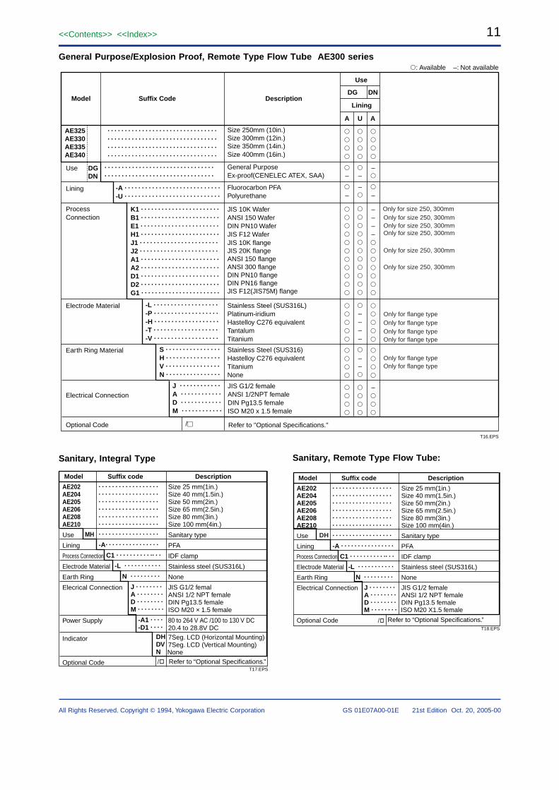
General Purpose/Explosion Proof, Remote Type Flow Tube AE300 series
AE325AE330AE335AE340
. . . . . . . . . . . . . . . . . . . . . . . . . . . . . . . .
. . . . . . . . . . . . . . . . . . . . . . . . . . . . . . . .
-A . . . . . . . . . . . . . . . . . . . . . . . . . . . .
-U . . . . . . . . . . . . . . . . . . . . . . . . . . . .
K1 . . . . . . . . . . . . . . . . . . . . . . .
B1 . . . . . . . . . . . . . . . . . . . . . . .
E1 . . . . . . . . . . . . . . . . . . . . . . .
H1 . . . . . . . . . . . . . . . . . . . . . . .
J1 . . . . . . . . . . . . . . . . . . . . . . .
J2 . . . . . . . . . . . . . . . . . . . . . . .
A1 . . . . . . . . . . . . . . . . . . . . . . .
A2 . . . . . . . . . . . . . . . . . . . . . . .
D1 . . . . . . . . . . . . . . . . . . . . . . .
D2 . . . . . . . . . . . . . . . . . . . . . . .
G1 . . . . . . . . . . . . . . . . . . . . . . .
-L . . . . . . . . . . . . . . . . . . .
-P . . . . . . . . . . . . . . . . . . .
-H . . . . . . . . . . . . . . . . . . .
-T . . . . . . . . . . . . . . . . . . .
-V . . . . . . . . . . . . . . . . . . .
S . . . . . . . . . . . . . . . .
H . . . . . . . . . . . . . . . .
V . . . . . . . . . . . . . . . .
N . . . . . . . . . . . . . . . .
J . . . . . . . . . . . .
A . . . . . . . . . . . .
D . . . . . . . . . . . .
M . . . . . . . . . . . .
/
Size 250mm (10in.)Size 300mm (12in.)Size 350mm (14in.)Size 400mm (16in.)
General PurposeEx-proof(CENELEC ATEX, SAA)
Fluorocarbon PFAPolyurethane
JIS 10K WaferANSI 150 WaferDIN PN10 WaferJIS F12 WaferJIS 10K flangeJIS 20K flangeANSI 150 flangeANSI 300 flangeDIN PN10 flangeDIN PN16 flangeJIS F12(JIS75M) flange
Stainless Steel (SUS316L)Platinum-iridiumHastelloy C276 equivalentTantalumTitanium
Stainless Steel (SUS316)Hastelloy C276 equivalentTitaniumNone
Lining
A U A
–
–
–
–
––––
––
–
–
––––
–
Suffix CodeModel Description
Use
DG DN
: Available –: Not available
Use DGDN
Lining
Process Connection
Electrode Material
Earth Ring Material
Electrical Connection
Refer to "Optional Specifications."
JIS G1/2 femaleANSI 1/2NPT femaleDIN Pg13.5 femaleISO M20 x 1.5 female
Optional Code
T16.EPS
. . . . . . . . . . . . . . . . . . . . . . . . . . . . . . . .
. . . . . . . . . . . . . . . . . . . . . . . . . . . . . . . .
. . . . . . . . . . . . . . . . . . . . . . . . . . . . . . . .
. . . . . . . . . . . . . . . . . . . . . . . . . . . . . . . .
Only for size 250, 300mm
Only for size 250, 300mm
Only for size 250, 300mmOnly for size 250, 300mm
Only for size 250, 300mm
Only for size 250, 300mm
Only for flange typeOnly for flange typeOnly for flange typeOnly for flange type
Only for flange typeOnly for flange type
Sanitary, Integral Type
AE202AE204AE205AE206AE208AE210
Use
Lining
Process Connection
Electrode Material
Earth Ring
Elecrical Connection
Power Supply
Indicator
Optional Code Refer to “Optional Specifications.”None
. . . . . . . . . . . . . . . . . .
-A. . . . . . . . . . . . . . . .
C1 . . . . . . . . . . .. . .
-L . . . . . . . . . . .
N . . . . . . . . .
J . . . . . . . .A . . . . . . . .D . . . . . . . .M . . . . . . . .
-A1 . . . .-D1 . . . .
DHDVN
Model Suffix code Description
Size 25 mm(1in.)Size 40 mm(1.5in.)Size 50 mm(2in.)Size 65 mm(2.5in.)Size 80 mm(3in.)Size 100 mm(4in.)
Sanitary type
PFA
IDF clamp
Stainless steel (SUS316L)
None
JIS G1/2 femalANSI 1/2 NPT femaleDIN Pg13.5 femaleISO M20 × 1.5 female
80 to 264 V AC /100 to 130 V DC20.4 to 28.8V DC7Seg. LCD (Horizontal Mounting)7Seg. LCD (Vertical Mounting)
. . . . . . . . . . . . . . . . . .
. . . . . . . . . . . . . . . . . .
. . . . . . . . . . . . . . . . . .
. . . . . . . . . . . . . . . . . .
. . . . . . . . . . . . . . . . . .
. . . . . . . . . . . . . . . . . .
T17.EPS
MH
/
Sanitary, Remote Type Flow Tube:
AE202AE204AE205AE206AE208AE210
Use
Lining
Process Connection
Electrode Material
Earth Ring
Electrical Connection
Optional Code Refer to “Optional Specifications.”
ISO M20 X1.5 female
. . . . . . . . . . . . . . . . . .
-A . . . . . . . . . . . . . . . .
C1 . . . . . . . . . . .. . .
-L . . . . . . . . . . .
N . . . . . . . . .
J . . . . . . . .A . . . . . . . .D . . . . . . . .M . . . . . . . .
Model Suffix code Description
Size 25 mm(1in.)Size 40 mm(1.5in.)Size 50 mm(2in.)Size 65 mm(2.5in.)Size 80 mm(3in.)Size 100 mm(4in.)
Sanitary type
PFA
IDF clamp
Stainless steel (SUS316L)
None
JIS G1/2 femaleANSI 1/2 NPT femaleDIN Pg13.5 female
. . . . . . . . . . . . . . . . . .
. . . . . . . . . . . . . . . . . .
. . . . . . . . . . . . . . . . . .
. . . . . . . . . . . . . . . . . .
. . . . . . . . . . . . . . . . . .
. . . . . . . . . . . . . . . . . .
T18.EPS
DH
/
12<<Contents>> <<Index>>
GS 01E07A00-01E 21st Edition Oct. 20, 2005-00All Rights Reserved. Copyright © 1994, Yokogawa Electric Corporation
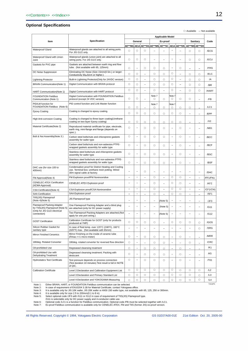
Optional Specifications
Item Specification CodeSanitaryEx-proof
Applicable Model
General
AE***DHAE***MHAE***DNAE14AE***DGAE***MG AE14 AE***MNWaterproof glands are attached to all wiring ports. For JIS G1/2 only.
Waterproof glands (union joint) are attached to all wiring ports. For JIS G1/2 only.
Gaskets are attached between earth ring and flow tube. (Not available with 65, 125mm)
Eliminating DC Noise (Size 15mm(0.5in.) or larger: Conductivity 50S/cm or higher.)
Built-in Lightning Protector(Only for 24VDC version)
Digital Communication with BRAIN protocol
Digital Communication with HART protocol
Digital Communication with FOUNDATION Fieldbus protocol (except 24 VDC version)
PID control function and Link Master function
Coating is changed to epoxy coating.
Coating is changed to three-layer coating(Urethane coating on two-layer Epoxy coating)
Reproduced material certificate for pipe, electrode, earth ring, mini-flange and flange (depends on spec.).
Carbon steel bolts/nuts and chloroprene gaskets assembly for wafer type
Carbon steel bolts/nuts and non-asbestos PTFE-wrapped gaskets assembly for wafer type
Stainless steel bolts/nuts and chloroprene gaskets assembly for wafer type
Stainless steel bolts/nuts and non-asbestos PTFE-wrapped gaskets assembly for wafer type
Condensation proof for District Heating and Cooling use. Terminal box; urethane resin potting. Wired 30m signal cable at factory.
FM Explosion proof/FM Nonincendive
CENELEC ATEX Explosion proof
CSA Explosion proof/CSA Nonincendive
SAA Explosion proof
JIS Flameproof type
One Flameproof Packing Adapter and a blind plug are attached.(only for DC power supply)
Two Flameproof Packing Adapters are attached.(Not apply for one port wiring.)
Calibration Certificate for GOST (only for products produced at YMF)
In case of fluid temp. over 120°C (248°F), 160°C (320°F) max. (Not available with 65mm)
Mirror Finishing on the inside of ceramic tube (Rmax.<=1 micro-meter)
180deg. rotated converter for reversed flow direction
Degreased cleansing treatment
Degreased cleansing treatment; Packing with desiccant
Test pressure depends on process connection(Test duration 10 minutes) Test result is full in NOTE of QIC.
Level 2:Declaration and Calibration Equipment List
Level 3:Declaration and Primary Standard List
Level 4:Declaration and YOKOGAWA Measuring
Waterproof Gland
Waterproof Gland with Union Joint
Gaskets for PVC pipe
DC Noise Suppression
Lightning Protector
BRAIN Communication(Note 1)
HART Communication(Note 1)
FOUNDATION Fieldbus Communication (Note 1)
PID/LM function for FOUNDATION Fieldbus (Note 6)
Epoxy Coating
High Anti-corrosion Coating
Material Certificate(Note 2)
Bolt & Nut Assembly(Note 3 )
DHC use (for size 100 to 400mm)
FM Approval(Note 4)
CENELEC ATEX Certification (KEMA Approval)
CSA Certification(Note 4)
SAA Certification
TIIS(JIS) Flameproof(Note 4)(Note 5)
Flameproof Packing Adapterfor TIIS(JIS) Flameproof (Note 5)(Only for JIS G1/2 electrical connection)
GOST Certification
Silicon Rubber Gasket for sanitary type
Mirror Finished Ceramics
180deg. Rotated Converter
Oil-prohibited Use
Oil-prohibited Use with Dehydrating Treatment
Hydrostatics Test Certificate
Calibration Certificate
T19.EPSNote 1: Either BRAIN, HART, or FOUNDATION Fieldbus communication can be selected.Note 2: In case of requirement of EN10204 3.1B for Material Certificate, contact Yokogawa office.Note 3: It is available only for JIS 10K wafer, JIS 20K wafer or ANSI 150 wafer type, not available with 65, 125, 250 or 300mm.Note 4: It is available only for size 2.5 to 200mm(0.1 to 8 in). Note 5: Select optional code /JF3 with /G11 or /G12 in case of requirement of TIIS(JIS) Flameproof type.
/G11 is selectable only for DC power supply and 4-conductor cable use.Note 6: Optional code /LC1 is a function for Fieldbus communication. Optional code /FB must be selected together with /LC1.Note 7: Ex-proof Fieldbus communication is available only for CENELEC ATEX, FM and TIIS (former JIS) ex-proof version.
: Available –: Not available
AE***SC
–
–
–
–
–
–
–
–
–
–
–
–
–
–
–
–
–
–
–
–
–
–
–
–
–
–
–
–
–
–
–
–
–
–
–
–
–
–
–
–
–
–
–
–
–
–
–
–
–
–
–
–
–
–
–
–
–
–
–
(Note 5)
(Note 5)
(Note 5)
–
–
–
–
–
–
–
–
–
–
–
–
–
–
–
–
–
–
–
–
–
–
–
–
–
–
–
–
–
–
–
–
–
–
–
–
–
–
–
–
–
–
–
–
–
–
–
–
–
–
–
–
–
–
–
–
–
–
–
–
–
–
–
–
–
–
–
–
–
–
–
–
–
–
–
–
/ECG
/ECU
/FRG
/ELC
/A
/BR
/HART
/FB
/LC1
/EPF
/X2
/M01
/BCC
/BCF
/BSC
/BSF
/DHC
/FF1/FN1
/KF2
/CF1/CN1
/SF1
/JF3
/G11
/G12
/GOS
/SRG
/MRR
/CRC
/K1
/K5
/T01
/L2
/L3
/L4
Note 7
Note 7
Note 7
Note 7
13<<Contents>> <<Index>>
All Rights Reserved. Copyright © 1994, Yokogawa Electric Corporation GS 01E07A00-01E 21st Edition Oct. 20, 2005-00
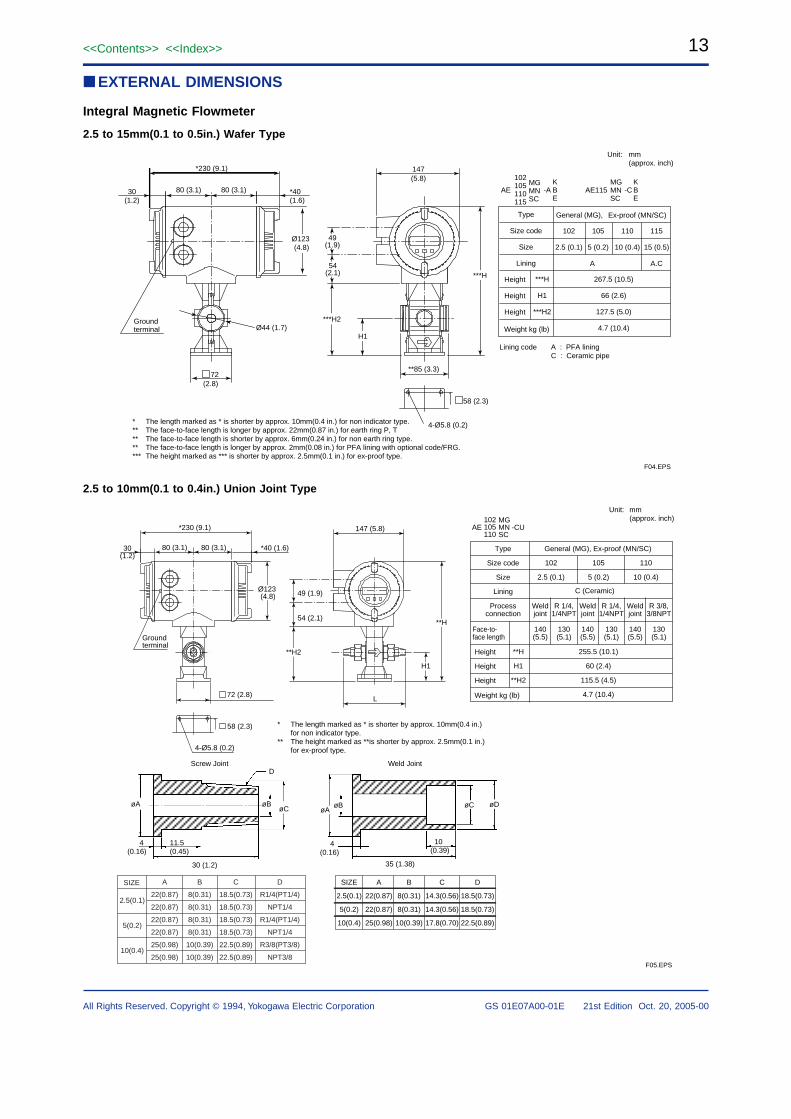
EXTERNAL DIMENSIONS
Integral Magnetic Flowmeter
2.5 to 15mm(0.1 to 0.5in.) Wafer Type
F04.EPS
*230 (9.1)
80 (3.1) 80 (3.1)30(1.2)
*40(1.6)
Groundterminal Ø44 (1.7)
72(2.8)
54(2.1)
***H2
H1
***H
**85 (3.3)
58 (2.3)
4-Ø5.8 (0.2)
147(5.8)
Ø123 (4.8)
49(1.9)
Unit: mm(approx. inch)
AE
Lining code A : PFA liningC : Ceramic pipe
AE115-A
102105110115
KBE
MGMNSC
-CKBE
Type
Size code
Size
Lining
267.5 (10.5)
66 (2.6)
127.5 (5.0)
4.7 (10.4)
102
2.5 (0.1)
105
5 (0.2)
110
10 (0.4)
115
15 (0.5)
A A.C
Height
Height
Height
***H
H1
***H2
Weight kg (lb)
General (MG),
MGMNSC
Ex-proof (MN/SC)
* The length marked as * is shorter by approx. 10mm(0.4 in.) for non indicator type.** The face-to-face length is longer by approx. 22mm(0.87 in.) for earth ring P, T** The face-to-face length is shorter by approx. 6mm(0.24 in.) for non earth ring type.** The face-to-face length is longer by approx. 2mm(0.08 in.) for PFA lining with optional code/FRG.*** The height marked as *** is shorter by approx. 2.5mm(0.1 in.) for ex-proof type.
2.5 to 10mm(0.1 to 0.4in.) Union Joint Type
Unit: mm(approx. inch)
30(1.2)
80 (3.1) 80 (3.1) *40 (1.6)
Groundterminal
4-Ø5.8 (0.2)
58 (2.3)
72 (2.8) L
147 (5.8)*230 (9.1)
49 (1.9)
54 (2.1)
**H2
**H
H1
Ø123 (4.8)
øAøA
øBøCøB
D
4(0.16)
4(0.16)
11.5(0.45)
30 (1.2)
10(0.39)
35 (1.38)
øDøC
AEMGMNSC
-CU102105110
Type
Size code
Size
Lining
102
2.5 (0.1)
105
5 (0.2)
110
10 (0.4)
Processconnection
Weldjoint
Face-to-face length
140(5.5)
R 1/4,1/4NPT
130(5.1)
Weldjoint
140(5.5)
R 1/4,1/4NPT
130(5.1)
Weldjoint
140(5.5)
R 3/8,3/8NPT
130(5.1)
Height
Height
Height
**H
H1
**H2
255.5 (10.1)
60 (2.4)
115.5 (4.5)
4.7 (10.4)Weight kg (lb)
General (MG), Ex-proof (MN/SC)
C (Ceramic)
SIZE
2.5(0.1)
5(0.2)
10(0.4)
A
22(0.87)
22(0.87)
22(0.87)
22(0.87)
25(0.98)
25(0.98)
B
8(0.31)
8(0.31)
8(0.31)
8(0.31)
10(0.39)
10(0.39)
C
18.5(0.73)
18.5(0.73)
18.5(0.73)
18.5(0.73)
22.5(0.89)
22.5(0.89)
D
R1/4(PT1/4)
NPT1/4
R1/4(PT1/4)
NPT1/4
R3/8(PT3/8)
NPT3/8
SIZE
2.5(0.1)
5(0.2)
10(0.4)
A
22(0.87)
22(0.87)
25(0.98)
B
8(0.31)
8(0.31)
10(0.39)
C
14.3(0.56)
14.3(0.56)
17.8(0.70)
D
18.5(0.73)
18.5(0.73)
22.5(0.89)
* The length marked as * is shorter by approx. 10mm(0.4 in.) for non indicator type.
** The height marked as **is shorter by approx. 2.5mm(0.1 in.) for ex-proof type.
F05.EPS
Screw Joint Weld Joint
14<<Contents>> <<Index>>
GS 01E07A00-01E 21st Edition Oct. 20, 2005-00All Rights Reserved. Copyright © 1994, Yokogawa Electric Corporation
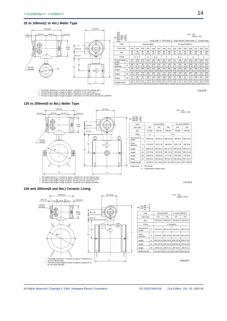
25 to 100mm(1 to 4in.) Wafer Type
* The length marked as * is shorter by approx. 10mm(0.4 in.) for non indicator type.** The face-to-face length is longer by approx. 22mm(0.87 in.) for earth ring P, T** The face-to-face length is shorter by approx. 6mm(0.24 in.) for non earth ring type.** The face-to-face length is longer by approx. 2mm(0.08 in.) for PFA lining with optional code/FRG.
Unit: mm(approx. inch)
*230 (9.1)
30(1.2)
80 (3.1) 80 (3.1) *40 (1.6)
Groundterminal oD
**L
147 (5.8)
49 (1.9)
54 (2.1)
H1H2
H
o123 (4.8)
F06.EPS
AEMGMNSC
A-UC
202204205206208210
KBEH
Type
Size code
Size
Lining
Face-to-facelengthOuterdiameter
202
25(1)
93(3.7)68
(2.7)251(9.9)111(4.4)77
(3.0)4.6
(10.1)
204
A, U, C A, U C
40(1.5)
106(4.2)86
(3.4)271
(10.7)131(5.2)88
(3.4)5.5
(12.1)
205
50(2)
120(4.7)99
(3.9)284
(11.2)144(5.6)94
(3.7)6.5
(14.3)
208
80(3)
160(6.3)129(5.1)324
(12.7)184(7.2)119(4.7)9.6
(21.2)
206
65(2.5)
120(4.7)117(4.6)302
(11.9)162(6.4)104(4.1)7.5
(16.5)
210
100(4)
180(7.1)155(6.1)350
(13.8)210(8.2)132(5.2)12.5
(27.6)
208
80(3)
160(6.3)129(5.1)314
(12.3)174(6.8)109(4.3)9.2
(20.3)
210
100(4)
180(7.1)155(6.1)350
(13.8)210(8.2)132(5.2)12.3
(27.1)
202
25(1)
93(3.7)68
(2.7)249(9.8)109(4.3)75
(3.0)4.6
(10.1)
204
A, C AA C
40(1.5)
106(4.2)86
(3.4)269
(10.6)129(5.1)86
(3.4)5.5
(12.1)
205
50(2)
120(4.7)99
(3.9)282
(11.1)142(5.6)92
(3.6)6.5
(14.3)
208
80(3)
160(6.3)129(5.1)322
(12.7)182(7.1)117(4.6)9.6
(21.2)
210
100(4)
180(7.1)155(6.1)348
(13.7)208(8.2)130(5.1)12.5
(27.6)
208
80(3)
160(6.3)129(5.1)312
(12.3)172(6.8)107(4.2)9.2
(20.3)
210
100(4)
180(7.1)155(6.1)348
(13.7)208(8.2)130(5.1)12.3
(27.1)
Height
Height
Height
**L
D
H
H1
H2
Weight kg (lb)
General (MG) Ex-proof (MN/SC)
Lining code A : PFA lining U : Polyurethane rubber lining C : Ceramic pipe
125 to 200mm(5 to 8in.) Wafer Type
* The length marked as * is shorter by approx. 10mm(0.4 in.) for non indicator type.** The face-to-face length is shorter by approx. 6mm(0.24 in.) for non earth ring type.** The face-to-face length is longer by approx. 30mm(1.18 in.) for earth ring P, T.** The face-to-face length is longer by approx. 2mm(0.08 in.) for optional code/FRG.
*230 (9.1)
80 (3.1) 80 (3.1)30 (1.2) *40 (1.6)
oD
**L
54 (2.1)
49 (1.9)
147 (5.8)
Groundterminal
W
o123 (4.8)
H1
H2
H
F07.EPS
Unit: mm(approx. inch)
Lining code A : PFA lining
U : Polyurethane rubber lining
Type
Size code
Size
Lining
215
150 (6)
220
200 (8)
Height
Height
Height
Width
Face-to-facelength
Outerdiameter
**L
D
230 (9.1)
200 (7.9)
392 (15.4)
252 (9.9)
152 (6.0)
256 (10.1)
20.2 (44.5)
212
125 (5)
230 (9.1)
175 (6.9)
367(14.4)
227 (8.9)
140 (5.5)
230 (9.1)
18 (39.7)
442 (17.4)
302 (11.9)
177 (7.0)
307 (12.1)
30.7 (67.6)
300 (11.8)
250 (9.8)
215
150 (6)
220
200 (8)
230 (9.1)
200 (7.9)
390 (15.4)
250 (9.8)
150 (5.9)
256 (10.1)
23.2 (51.1)
440 (17.3)
300 (11.8)
175 (6.9)
307 (12.1)
35.7 (68.6)
300 (11.8)
250 (9.8)
H
H1
H2
W
Weight kg (lb)
General (MG) Ex-proof (MN/SC)
A, UA
AEMGMNSC
-212215220
AU
KBEH
150 and 200mm(6 and 8in.) Ceramic Lining
* The length marked as * is shorter by approx. 10mm(0.4 in.) for non indicator type.
** The face-to-face length is shorter by approx. 6mm(0.24 in.) for non earth ring type.
F08.EPS
*230 (9.1)
*40 (1.6)30 (1.2) 80(3.1)
80(3.1)
Groundterminal
ØD
147 (5.8)
**L
54 (2.1)
49 (1.9)
H1
H2
H
Ø123 (4.8)
AEMGMNSC
-215220 C
KBEH
Type
Size code
Size
Lining
215
150 (6.0)
220
200 (8.0)
Height
Height
Height
Face-to-facelength
Outerdiameter
**L
D
232 (9.2)
214 (8.4)
406 (16.0)
266 (10.5)
159 (6.3)
23.9 (52.6)
456 (18.0)
316 (12.4)
184 (7.2)
35.9 (79.1)
302 (11.9)
264 (10.4)
215
150 (6.0)
220
200 (8.0)
232 (9.2)
214 (8.4)
404 (15.9)
264 (10.4)
157 (6.2)
26.9 (59.3)
454 (17.9)
314 (12.4)
182 (7.2)
40.9 (90.1)
302 (11.9)
264 (10.4)
H
H1
H2
Weight kg (lb)
General (MG) Ex-proof (MN/SC)
C (Ceramic)
Unit: mm(approx. inch)
15<<Contents>> <<Index>>
All Rights Reserved. Copyright © 1994, Yokogawa Electric Corporation GS 01E07A00-01E 21st Edition Oct. 20, 2005-00
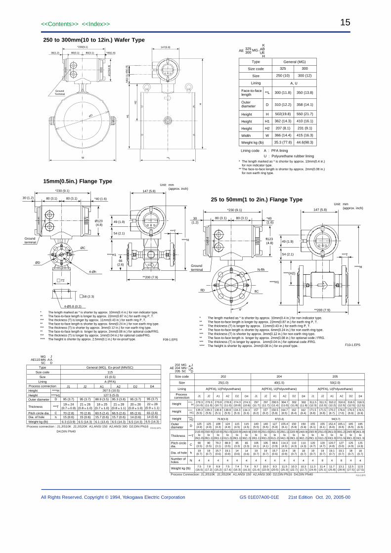
250 to 300mm(10 to 12in.) Wafer Type
15mm(0.5in.) Flange Type
25 to 50mm(1 to 2in.) Flange Type
F10-1.EPS
* The length marked as * is shorter by approx. 10mm(0.4 in.) for non indicator type.** The face-to-face length is longer by approx. 22mm(0.87 in.) for earth ring P, T.*** The thickness (T) is longer by approx. 11mm(0.43 in.) for earth ring P, T.** The face-to-face length is shorter by approx. 6mm(0.24 in.) for non earth ring type.*** The thickness (T) is shorter by approx. 3mm(0.12 in.) for non earth ring type.** The face-to-face length is longer by approx. 2mm(0.08 in.) for optional code / FRG.*** The thickness (T) is longer by approx. 1mm(0.04 in.) for optional code /FRG.**** The height is shorter by approx. 2mm(0.08 in.) for ex-proof type.
30(1.2)
80 (3.1) 80 (3.1)
Groundterminal N-flh
flCflD
fl123(4.8)
*230 (9.1)
*40 (1.6)
49 (1.9)
54 (2.1)
**200 (7.9)
***T
147 (5.8)
****(H2)
****H1
****H
Unit: mm(approx. inch)
øD
*230(9.1)
30(1.2) *40(1.6)
**L
54(2
.1)
49(1
.9)
147(5.8)
GroundTerminal
W
ø12
3(4.
8)
H1
HH2
80(3.1)80(3.1)
Unit: mm(approx. inch)
*230 (9.1)
80 (3.1) 80 (3.1)30 (1.2) *40 (1.6)
ØD
ØC
4-Øh
72
Groundterminal
147 (5.8)
49 (1.9)
54 (2.1)
**200 (7.9)
***T
Ø123 (4.8)
****H1
****H
66(2.6)
58 (2.3)
4-Ø5.8 (0.2)
* The length marked as * is shorter by approx. 10mm(0.4 in.) for non indicator type.** The face-to-face length is longer by approx. 22mm(0.87 in.) for earth ring P, T.*** The thickness (T) is longer by approx. 11mm(0.43 in.) for earth ring P, T.** The face-to-face length is shorter by approx. 6mm(0.24 in.) for non earth ring type.*** The thickness (T) is shorter by approx. 3mm(0.12 in.) for non earth ring type.** The face-to-face length is longer by approx. 2mm(0.08 in.) for optional code/FRG.*** The thickness (T) is longer by approx. 1mm(0.04 in.) for optional code/FRG.**** The height is shorter by approx. 2.5mm(0.1 in.) for ex-proof type. F09-1.EPS
Lining code A : PFA lining
U : Polyurethane rubber lining
Type
Size code
Size
Lining
325
250 (10)
300
300 (12)
Height
Height
Height
Width
Face-to-facelength
Outerdiameter
**L
D
300 (11.8)
310 (12.2)
502(19.8)
362 (14.3)
207 (8.1)
366 (14.4)
35.3 (77.8)
550 (21.7)
410 (16.1)
231 (9.1)
415 (16.3)
44.6(98.3)
350 (13.8)
358 (14.1)
H
H1
H2
W
Weight kg (lb)
General (MG)
A, U
AE MG -325300
AU
KBEH
* The length marked as * is shorter by approx. 10mm(0.4 in.) for non indicator type.
** The face-to-face length is shorter by approx. 2mm(0.08 in.) for non earth ring type.
AE AU
MGMNSC
202204205
JAD
Size code
Size
Lining
Process connection
202
25(1.0)
A(PFA), U(Polyurethane)
204
40(1.5)
A(PFA), U(Polyurethane)
205
50(2.0)
A(PFA), U(Polyurethane)
J1
76.8(3.0) 87(3.4) 94(3.7)
279.3(11.0)
J2 A1 A2 D2 J1 J2 A1 A2 D2 J1 J2 A1 A2 D2
Height
Height
Height
Weight kg (lb)
Outer diameter D
Thickness
Dia. of hole
Number of holes
Pitch circle dia.
***T
h
N
C
-
139.3(5.5)
125(4.9)
90(3.5)
19(0.7)
4
7.5(16.5)
21(0.8)to
26(1.0)
125(4.9)
90(3.5)
19(0.7)
4
7.8(17.2)
23(0.9)to
28(1.1)
108(4.3)
79.2(3.1)
15.7(0.6)
4
6.9(15.2)
21(0.8)to
28(1.1)
124(4.9)
88.9(3.5)
19.1(0.8)
4
7.5(17.4)
25(1.0)to
31(1.2)
115(4.5)
85(3.3)
14(0.6)
4
7.4(16.3)
22(0.9)to
28(1.1)
140(5.5)
105(4.1)
19(0.7)
4
9.7(21.4)
23(0.9)to
28(1.1)
140(5.5)
105(4.1)
19(0.7)
4
10.0(22.0)
25(1.0)to
30(1.2)
127(5.0)
98.6(3.9)
15.7(0.6)
4
9.3(20.5)
25(1.0)to
31(1.2)
155.4(6.1)
114.3(4.5)
22.4(0.9)
4
11.5(25.3)
28(1.1)to
34(1.3)
150(5.9)
110(4.3)
18(0.7)
4
10.3(22.7)
22(0.9)to
28(1.1)
155(6.1)
120(4.7)
19(0.7)
4
11.3(24.9)
23(0.9)to
29(1.1)
155(6.1)
120(4.7)
19(0.7)
8
11.4(25.1)
25(1.0)to
31(1.2)
152.4(6.0)
120.7(4.8)
19.1(0.7)
4
11.7(25.8)
26(1.0)to
33(1.3)
165.1(6.5)
127(5.0)
19.1(0.7)
8
13.1(28.9)
30(1.2)to
37(1.5)
165(6.5)
125(4.9)
18(0.7)
4
12.5(27.5)
24(0.9)to
30(1.2)
279.3(11.0)
139.3(5.5)
270.8(10.7)
130.8(5.1)
278.8(11.0)
138.8(5.5)
274.3(10.8)
134.3(5.3)
297(11.7)
157(6.2)
297(11.7)
157(6.2)
290.5(11.4)
150.5(5.9)
304.7(11.0)
164.7(6.5)
302(11.9)
162(6.4)
311.5(12.3)
171.5(6.8)
311.5(12.3)
171.5(6.8)
310.2(12.2)
170.2(6.7)
316.6(12.5)
176.6(7.0)
316.5(12.5)
176.5(6.9)
D4
115(4.5)
85(3.3)
14(0.6)
4
7.4(16.3)
24(0.9)to
30(1.2)
274.3(10.8)
134.3(5.3)
D4
150(5.9)
110(4.3)
18(0.7)
4
10.3(22.7)
24(0.9)to
30(1.2)
302(11.9)
162(6.4)
D4
165(6.5)
125(4.9)
18(0.7)
4
12.5(27.5)
26(1.0)to
33(1.3)
316.5(12.5)
176.5(6.9)
****
****
****
H
H1
H2
Process Connection: J1;JIS10K J2;JIS20K A1;ANSI 150 A2;ANSI 300 D2;DIN PN16 D4;DIN PN40 F10-2.EPS
AE115MGMNSC
-AJAD
Type
Size code
Size
Lining
115
15 (0.5)
A (PFA)Process connection
95 (3.7)
19 to 24(0.7 to 0.9)
21 to 26(0.8 to 1.0)
18 to 25(0.7 to 1.0)
21 to 28(0.8 to 1.1)
20 to 26(0.8 to 1.0)
70 (2.8)15 (0.6)
6.3 (13.9)
95 (3.7)
70 (2.8)15 (0.6)
6.5 (14.3)
88.9 (3.5)
60.5 (2.4)15.7 (0.6)
6.1 (13.4)
95.3 (3.8)
66.5 (2.6)15.7 (0.6)
6.5 (14.3)
95 (3.7)
65 (2.6)14 (0.6)
6.5 (14.3)
Height
Height
****H
****H1D
***T
J1 J2 A1
General (MG),
267.5 (10.5)
127.5 (5.0)
A2 D2
Ex-proof (MN/SC)
ChDia. of hole
Weight kg (lb)
Outer diameter
Pitch circle dia.
Thickness
Process connection : J1;JIS10K J2;JIS20K A1;ANSI 150 A2;ANSI 300 D2;DIN PN16
D4;DIN PN40
22 to 28(0.9 to 1.1)
95 (3.7)
65 (2.6)14 (0.6)
6.5 (14.3)
D4
F09-02.EPS
16<<Contents>> <<Index>>
GS 01E07A00-01E 21st Edition Oct. 20, 2005-00All Rights Reserved. Copyright © 1994, Yokogawa Electric Corporation
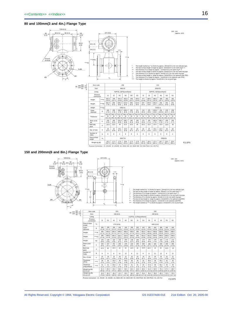
80 and 100mm(3 and 4in.) Flange Type
* The length marked as * is shorter by approx. 10mm(0.4 in.) for non indicator type.** The face-to-face length is longer by approx. 22mm(0.87 in.) for earth ring P, T.*** The thickness (T) is longer by approx. 11mm(0.43 in.) for earth ring P, T.** The face-to-face length is shorter by approx. 6mm(0.24 in.) for non earth ring type.*** The thickness (T) is shorter by approx. 3mm(0.12 in.) for non earth ring type.** The face-to-face length is longer by approx. 2mm(0.08 in.) for optional code /FRG.*** The thickness (T) is longer by approx. 1mm(0.04 in.) for optional code /FRG.**** The height is shorter by approx. 2mm(0.08 in.) for ex-proof type.
Unit: mm(approx. inch)
F11.EPS
*230 (9.1)
80 (3.1) 80 (3.1)30(1.2)
*40 (1.6)
ØDØC
N-Øh
147 (5.8)
**L
***T
49 (1.9)
54 (2.1)
****H1
****H
Ø123(4.8)
****(H2)Groundterminal
AEMGMNSC
AU
208210
JADG
Size code
Size
Lining
Process connection
208
80(3.0)
A(PFA), U(Polyurethane)
210
100(4.0)
A(PFA), U(Polyurethane)
J1
109(4.3) 132(5.2)
341.5(13.4)
J2 A1 A2 D2 G1 J1 J2 A1 A2 D2 G1
Height
Height
Height
Weight kg (lb)
Outer diameter D
Thickness
Dia. of hole
Number of holes
Face-to-facelength
Pitch circle dia.
****H
****H1
****H2
***T
h
N
**L 200(7.9) 250(9.8)
C
-
201.5(7.9)
185(7.3)
150(5.9)
19(0.7)
8
15.3(33.7)
25(1.0)to
31(1.2)
200(7.9)
160(6.3)
23(0.9)
8
17.3(38.1)
29(1.1)to
35(1.4)
190.5(7.5)
152.4(6.0)
19.1(0.7)
4
17.6(38.8)
31(1.2)to
38(1.5)
209.6(8.3)
168.1(6.6)
22.4(0.9)
8
20.6(45.4)
36(1.4)to
43(1.7)
200(7.9)
160(6.3)
18(0.7)
8
17.3(38.1)
26(1.0)to
32(1.3)
211(8.3)
168(6.6)
19(0.7)
4
17.8(39.2)
25(1.0)to
32(1.3)
210(8.3)
175(6.9)
19(0.7)
8
23.3(51.3)
25(1.0)to
31(1.5)
225(8.9)
185(7.3)
23(0.9)
8
26.5(58.4)
31(1.2)to
37(1.5)
228.6(9.0)
190.5(7.5)
19.1(0.7)
8
27.3(60.1)
31(1.2)to
38(1.5)
254(10.0)
200.2(7.9)
22.4(0.9)
8
34.7(76.4)
39(1.5)to
46(1.8)
220(8.7)
180(7.1)
18(0.7)
8
25.0(55.1)
26(1.0)to
32(1.3)
238(9.4)
195(7.7)
19(0.7)
4
26.4(58.1)
25(1.0)to
32(1.3)
349(13.7)
209(8.2)
344.3(13.6)
204.3(8.0)
353.8(13.9)
213.8(8.4)
349(13.7)
209(8.2)
354.5(14.0)
214.5(8.4)
377(14.8)
237(9.3)
384.5(15.1)
244.5(9.6)
386.3(15.2)
246.3(9.7)
399(15.7)
259(10.2)
382(15.0)
242(9.5)
391(15.4)
251(9.9)
Process Connection : J1; JIS10K J2; JIS20K A1; ANSI 150 A2; ANSI 300 D2; DIN PN16 G1; JIS F12
Bolt holepitch
45 45 4522.5 22.5 22.5 22.5 22.5 22.5
22.5 22.5 22.5
150 and 200mm(6 and 8in.) Flange Type
* The length marked as * is shorter by approx. 10mm(0.4 in.) for non indicator type.** The face-to-face length is longer by approx. 28mm(1.1 in.) for earth ring P, T.*** The thickness (T) is longer by approx. 14mm(0.55 in.) for earth ring P, T.** The face-to-face length is shorter by approx. 6mm(0.24 in.) for non earth ring type.*** The thickness (T) is shorter by approx. 3mm(0.12 in.) for non earth ring type.** The face-to-face length is longer by approx. 2mm(0.08 in.) for optional code/FRG.*** The thickness (T) is longer by approx. 1mm(0.04 in.) for optional code/FRG.**** The height marked as **** is shorter by approx. 2mm(0.08 in.) for ex-proof type.
F12.EPS
Unit: mm(approx. inch)
147 (5.8)*230 (9.1)
80(3.1)
80(3.1)
*40 (1.6)
30(1.2)
Groundterminal
49 (1.9)
54 (2.1)
**L
N-Øh
ØD ØC
***TØ123 (4.8)
****H1
H2
****H
Size code
Size
Lining
Face-to-facelength
Outerdiameter
280(11.0)
435(17.1)
295(11.6)
143(5.6)
240(9.4)
23(0.9)
30(1.2)
31(1.2)
31.3(68.9)
23(0.9)
33.4(1.3)
34.4(1.4)
33.3(73.3)
25(1.0)
36(1.4)
37(1.5)
39.3(86.6)
22(0.9)
44.5(1.8)
45.5(1.8)
50.3(110.8)
22(0.9)
30(1.2)
31(1.2)
33.3(73.3)
19(0.7)
32(1.3)
33(1.3)
48.3(106.4)
23(0.9)
36.4(1.4)
37.4(1.5)
51.3(113.0)
22(0.9)
32(1.2)
33(1.3)
47.3(104.2)
22(0.9)
32(1.2)
33(1.3)
48.3(106.4)
25(1.0)
38(1.5)
39(1.5)
54.3(120.0)
25(1.0)
49.1(1.9)
50.1(2.0)
75.3(165.9)
23(0.9)
30(1.2)
31(1.2)
43.3(95.4)
19(0.7)
30(1.2)
31(1.2)
33.3(73.3)
8 6 8 8 8 8 1212121212 8 12
290(11.4)
440.5(17.3)
300.5(11.8)
148(5.8)
247(9.7)
280(11.0)
245.5(17.1)
295.5(11.6)
143(5.6)
241(9.5)
305(12.0)
448.5(17.7)
308.5(12.1)
156(6.1)
260(10.2)
320(12.6)
455.5(17.9)
315.5(12.4)
163(6.4)
270(10.6)
285(11.2)
438.5(17.3)
298.5(11.8)
146(5.7)
240(9.4)
330(13.0)
485(19.1)
345(13.6)
168(6.6)
290(11.4)
342(13.5)
491.5(19.4)
351.5(13.8)
174(6.9)
299(11.8)
345(13.6)
491.5(19.4)
351.5(13.8)
176(6.9)
298(11.7)
350(13.8)
495.5(19.5)
355.5(14.0)
178(7.0)
305(12.0)
380(15.0)
508.5(20.0)
368.5(14.5)
193(7.6)
330(13.0)
340(13.4)
488.5(19.2)
348.5(13.7)
173(6.8)
295(11.6)
340(13.4)
488.5(19.2)
348.5(13.7)
173(6.8)
295(11.6)
Height
Height
Height
Pitch circledia.
Number ofholes
Dia. of hole
Thickness(PFA)
Thickness(Polyurethane)
**L
D
****H
****H1
H2
C
N
h
***T
***T
Weight kg (lb)
215
150 (6.0) 200 (8.0)
220
Processconnection J1 G1 A1 J2 A2 D2 J1 G1 A1 J2 A2 D1 D2
270 (10.6) 340 (13.4)
A (PFA). U (Polyurethane)
AEMGMNSC
AU
215220
JADG
-
Process connection : J1; JIS10K J2; JIS20K A1; ANSI 150 A2; ANSI 300 D1; DIN PN10 D2; DIN PN16 G1; JIS F12
34.3(75.6)
36.3(80.0)
42.3(93.2)
53.3(117.4)
36.3(80.0)
53.3(117.4)
56.3(124.0)
52.3(115.2)
53.3(117.4)
59.3(130.6)
80.3(176.9)
48.3(106.4)
36.3(80.0)
Weight kg (lb)(General)
(Ex-proof)
Bolt holepitch
22.5 22.5
30 22.5 22.5 22.5 22.515 15 15 15 15 15
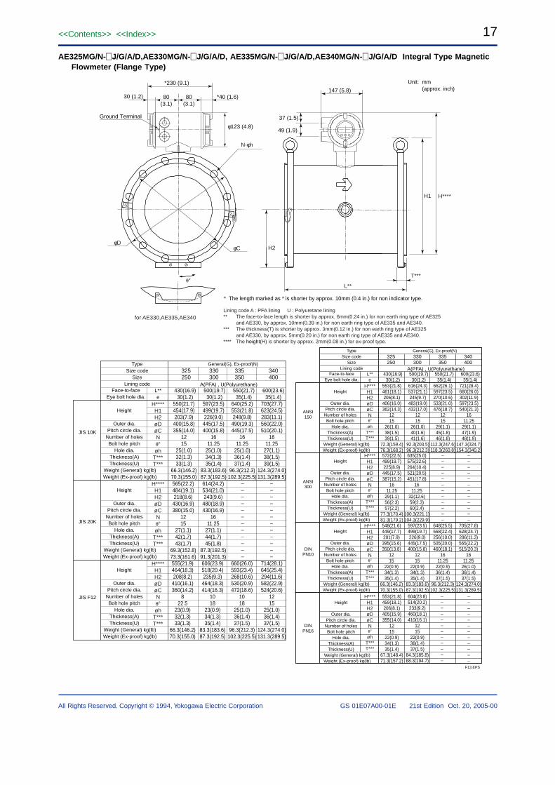
17<<Contents>> <<Index>>
All Rights Reserved. Copyright © 1994, Yokogawa Electric Corporation GS 01E07A00-01E 21st Edition Oct. 20, 2005-00
AE325MG/N-J/G/A/D,AE330MG/N-J/G/A/D, AE335MG/N-J/G/A/D,AE340MG/N-J/G/A/D Integral Type MagneticFlowmeter (Flange Type)
* The length marked as * is shorter by approx. 10mm (0.4 in.) for non indicator type.
Unit: mm(approx. inch)
F13.EPS
H1 H****
L**
H2φD
N-φh
φC
T***
for AE330,AE335,AE340
147 (5.8)30 (1.2)
49 (1.9)
*230 (9.1)
80(3.1)
80(3.1)
*40 (1.6)
Ground Terminal
φ123 (4.8)
37 (1.5)
JIS 10K
JIS 20K
JIS F12
H****H1H2øDøCNøh
T***T***
L**e
H****H1H2øDøCNøh
T***T***
H****H1H2øDøCNøh
T***T***
General(G), Ex-proof(N)
A(PFA) , U(Polyurethane)
––––––––––––
––––––––––––
Height
Outer dia.Pitch circle dia.
Number of holesBolt hole pitch
Hole dia.Thickness(A)Thickness(U)
Weight (General) kg(lb) Weight (Ex-proof) kg(lb)
TypeSize code
SizeLining code
Face-to-faceEye bolt hole dia.
Height
Outer dia.Pitch circle dia.
Number of holesBolt hole pitch
Hole dia.Thickness(A)Thickness(U)
Weight (General) kg(lb) Weight (Ex-proof) kg(lb)
Height
Outer dia.Pitch circle dia.
Number of holesBolt hole pitch
Hole dia.Thickness(A)Thickness(U)
Weight (General) kg(lb) Weight (Ex-proof) kg(lb)
325250
330300
335350
340400
430(16.9)30(1.2)
550(21.7)454(17.9)203(7.9)
400(15.8)355(14.0)
1215
25(1.0)32(1.3)33(1.3)
66.3(146.2)70.3(155.0)
500(19.7)30(1.2)
597(23.5)499(19.7)226(9.0)
445(17.5)400(15.8)
1611.25
25(1.0)34(1.3)35(1.4)
83.3(183.6)87.3(192.5)
550(21.7)35(1.4)
640(25.2)553(21.8)248(9.8)
490(19.3)445(17.5)
1611.25
25(1.0)36(1.4)37(1.4)
96.3(212.3)102.3(225.5)
600(23.6)35(1.4)
703(27.7)623(24.5)283(11.1)560(22.0)510(20.1)
1611.25
27(1.1)38(1.5)39(1.5)
124.3(274.0)131.3(289.5)
565(22.2)484(19.1)218(8.6)
430(16.9)380(15.0)
1215
27(1.1)42(1.7)43(1.7)
69.3(152.8)73.3(161.6)
614(24.2)534(21.0)243(9.6)
480(18.9)430(16.9)
1611.25
27(1.1)44(1.7)45(1.8)
87.3(192.5)91.3(201.3)
555(21.9)464(18.3)208(8.2)
410(16.1)360(14.2)
822.5
23(0.9)32(1.3)33(1.3)
66.3(146.2)70.3(155.0)
606(23.9)518(20.4)235(9.3)
464(18.3)414(16.3)
1018
23(0.9)34(1.3)35(1.4)
83.3(183.6)87.3(192.5)
660(26.0)593(23.4)268(10.6)530(20.9)472(18.6)
1018
25(1.0)36(1.4)37(1.5)
96.3(212.3)102.3(225.5)
714(28.1)645(25.4)294(11.6)582(22.9)524(20.6)
1215
25(1.0)36(1.4)37(1.5)
124.3(274.0)131.3(289.5)
Lining code A : PFA lining U : Polyuretane lining** The face-to-face length is shorter by approx. 6mm(0.24 in.) for non earth ring type of AE325
and AE330, by approx. 10mm(0.39 in.) for non earth ring type of AE335 and AE340.*** The thickness(T) is shorter by approx. 3mm(0.12 in.) for non earth ring type of AE325
and AE330, by approx. 5mm(0.20 in.) for non earth ring type of AE335 and AE340.**** The height(H) is shorter by approx. 2mm(0.08 in.) for ex-proof type.
H****H1H2øDøCN
øhT***T***
L**e
H****H1H2øDøCN
øhT***T***
H****H1H2øDøCN
øhT***T***
General(G), Ex-proof(N)
A(PFA) , U(Polyurethane)
––––––––––––
––––––––––––
––––––––––––
––––––––––––
Height
Outer dia.Pitch circle dia.
Number of holesBolt hole pitch
Hole dia.Thickness(A)Thickness(U)
Weight (General) kg(lb) Weight (Ex-proof) kg(lb)
TypeSize code
SizeLining code
Face-to-faceEye bolt hole dia.
Height
Outer dia.Pitch circle dia.
Number of holesBolt hole pitch
Hole dia.Thickness(A)Thickness(U)
Weight (General) kg(lb) Weight (Ex-proof) kg(lb)
Height
Outer dia.Pitch circle dia.
Number of holesBolt hole pitch
Hole dia.Thickness(A)Thickness(U)
Weight (General) kg(lb) Weight (Ex-proof) kg(lb)
325250
330300
335350
340400
430(16.9)30(1.2)
553(21.8)461(18.1)206(8.1)406(16.0)362(14.3)
1215
26(1.0)38(1.5)39(1.5)
72.3(159.4)76.3(168.2)
500(19.7)30(1.2)
616(24.3)537(21.1)245(9.7)483(19.0)432(17.0)
1215
26(1.0)40(1.6)41(1.6)
92.3(203.5)96.3(212.3)
550(21.7)35(1.4)
662(26.1)597(23.5)270(10.6)533(21.0)476(18.7)
1215
29(1.1)45(1.8)46(1.8)
112.3(247.6)118.3(260.8)
600(23.6)35(1.4)
721(28.4)660(26.0)302(11.9)597(23.5)540(21.3)
1611.25
29(1.1)47(1.9)48(1.9)
147.3(324.7)154.3(340.2)
572(22.5)499(19.7)225(8.9)445(17.5)387(15.2)
1611.25
29(1.1)56(2.3)57(2.2)
77.3(170.4)81.3(179.2)
635(25.0)575(22.6)264(10.4)521(20.5)451(17.8)
1611.25
32(12.6)59(2.3)60(2.4)
100.3(221.1)104.3(229.9)
548(21.6)449(17.7)201(7.9)395(15.6)350(13.8)
1215
22(0.9)34(1.3)35(1.4)
66.3(146.2)70.3(155.0)
597(23.5)499(19.7)226(9.0)445(17.5)400(15.8)
1215
22(0.9)34(1.3)35(1.4)
83.3(183.6)87.3(192.5)
648(25.5)568(22.4)256(10.0)505(20.0)460(18.1)
1611.25
22(0.9)36(1.4)37(1.5)
96.3(212.3)102.3(225.5)
705(27.8)628(24.7)286(11.3)565(22.2)515(20.3)
1611.25
26(1.0)36(1.4)37(1.5)
124.3(274.0)131.3(289.5)
ANSI150
ANSI300
DINPN10
H****H1H2øDøCN
øhT***T***
Height
Outer dia.Pitch circle dia.
Number of holesBolt hole pitch
Hole dia.Thickness(A)Thickness(U)
Weight (General) kg(lb) Weight (Ex-proof) kg(lb)
553(21.8)459(18.1)206(8.1)405(15.9)355(14.0)
1215
22(0.9)34(1.3)35(1.4)
67.3(148.4)71.3(157.2)
604(23.8)514(20.2)233(9.2)460(18.1)410(16.1)
1215
22(0.9)36(1.4)37(1.5)
84.3(185.8)88.3(194.7)
DINPN16
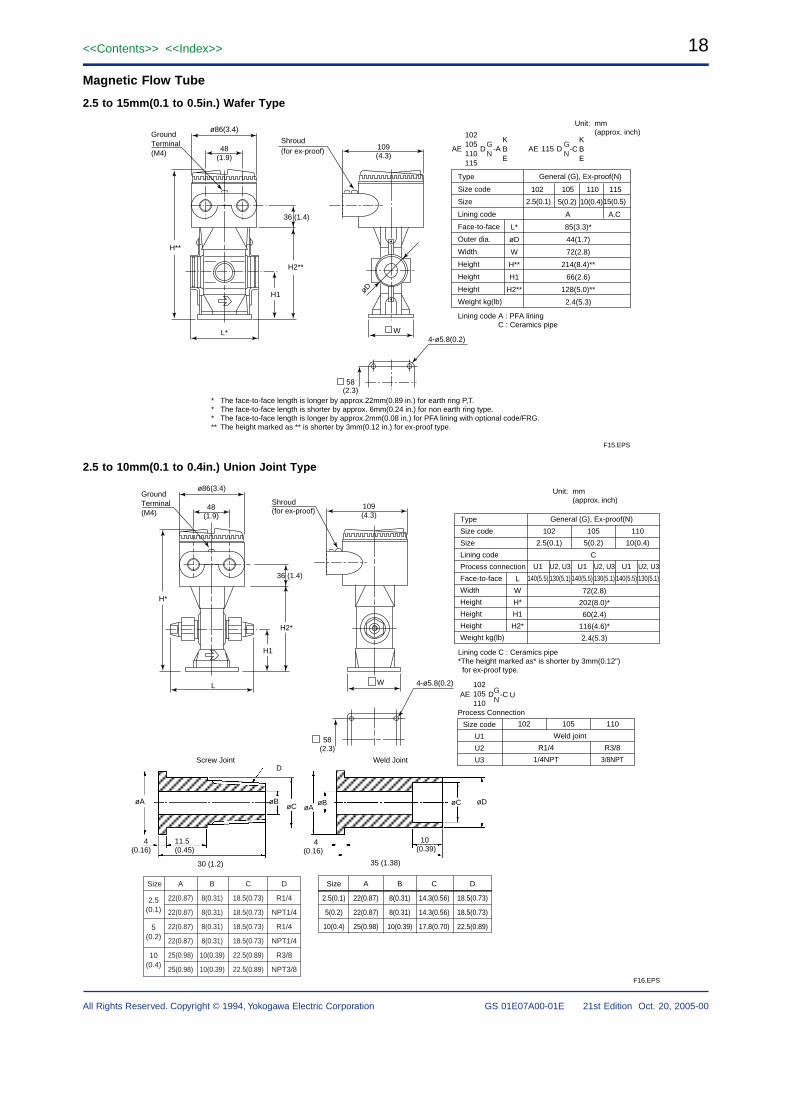
18<<Contents>> <<Index>>
GS 01E07A00-01E 21st Edition Oct. 20, 2005-00All Rights Reserved. Copyright © 1994, Yokogawa Electric Corporation
Magnetic Flow Tube
2.5 to 15mm(0.1 to 0.5in.) Wafer Type
Unit: mm(approx. inch)
* The face-to-face length is longer by approx.22mm(0.89 in.) for earth ring P,T.* The face-to-face length is shorter by approx. 6mm(0.24 in.) for non earth ring type. * The face-to-face length is longer by approx.2mm(0.08 in.) for PFA lining with optional code/FRG.** The height marked as ** is shorter by 3mm(0.12 in.) for ex-proof type.
H2**
L*
H1
36 (1.4)
ø86(3.4)
48(1.9)
øD
Shroud(for ex-proof) 109
(4.3)
W
58(2.3)
4-ø5.8(0.2)
H**
GroundTerminal(M4)
2.5(0.1)
A A.C
5(0.2) 10(0.4)15(0.5)
General (G), Ex-proof(N)
102 105 110 115
AE D -AKBE
102105110115
AE D -CKBE
115
Lining code A : PFA lining C : Ceramics pipe
Type
Size code
Size
Lining code
Face-to-face
Outer dia.
Width
Height
Height
Height
Weight kg(lb)
L*
øD
W
H**
H1
H2**
85(3.3)*
44(1.7)
72(2.8)
214(8.4)**
66(2.6)
128(5.0)**
2.4(5.3)
GN
GN
F15.EPS
2.5 to 10mm(0.1 to 0.4in.) Union Joint Type
F16.EPS
Unit: mm(approx. inch)
H*
H1
36 (1.4)
ø86(3.4)
109(4.3)
48(1.9)
L
H2*
W
58(2.3)
4-ø5.8(0.2)
GroundTerminal(M4)
Shroud(for ex-proof)
102
2.5(0.1)
105
5(0.2)
110
10(0.4)
U1
140(5.5)
U2, U3
130(5.1)
U1
140(5.5)
U2, U3
130(5.1)
U1
140(5.5)
U2, U3
130(5.1)
C
General (G), Ex-proof(N)Type
Size code
Size
Lining code
Process connection
Face-to-face
Width
Height
Height
Height
Weight kg(lb)
L
W
H*
H1
H2*
72(2.8)
202(8.0)*
60(2.4)
116(4.6)*
2.4(5.3)
Lining code C : Ceramics pipe*The height marked as* is shorter by 3mm(0.12") for ex-proof type.
102
1/4NPT
R1/4
3/8NPT
R3/8
105 110
Process Connection
AE D -C U102105110
Size code
U1
U2
U3
Weld joint
GN
Size
2.5(0.1)
5(0.2)
10(0.4)
A
22(0.87)
22(0.87)
22(0.87)
22(0.87)
25(0.98)
25(0.98)
B
8(0.31)
8(0.31)
8(0.31)
8(0.31)
10(0.39)
10(0.39)
C
18.5(0.73)
18.5(0.73)
18.5(0.73)
18.5(0.73)
22.5(0.89)
22.5(0.89)
D
R1/4
NPT1/4
R1/4
NPT1/4
R3/8
NPT3/8
Size
2.5(0.1)
5(0.2)
10(0.4)
A
22(0.87)
22(0.87)
25(0.98)
B
8(0.31)
8(0.31)
10(0.39)
C
14.3(0.56)
14.3(0.56)
17.8(0.70)
D
18.5(0.73)
18.5(0.73)
22.5(0.89)
øAøA
øBøCøB
D
4(0.16)
4(0.16)
11.5(0.45)
30 (1.2)
10(0.39)
35 (1.38)
øDøC
Screw Joint Weld Joint
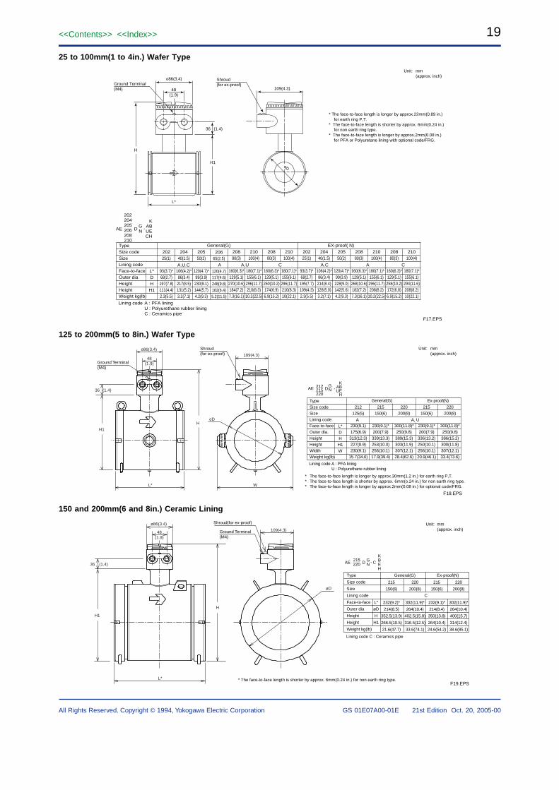
19<<Contents>> <<Index>>
All Rights Reserved. Copyright © 1994, Yokogawa Electric Corporation GS 01E07A00-01E 21st Edition Oct. 20, 2005-00
25 to 100mm(1 to 4in.) Wafer Type
* The face-to-face length is longer by approx.22mm(0.89 in.)for earth ring P,T.
* The face-to-face length is shorter by approx. 6mm(0.24 in.) for non earth ring type.
* The face-to-face length is longer by approx.2mm(0.08 in.)for PFA or Polyuretane lining with optional code/FRG.
Unit: mm(approx. inch)
H
36 (1.4)
H1
o86(3.4)
48(1.9)
L*
109(4.3)
oD
Ground Terminal(M4)
Shroud(for ex-proof)
F17.EPS
AE DGN
KABUECH
202204205206208210
-
TypeSize codeSizeLining codeFace-to-faceOuter diaHeightHeightWeight kg(lb)
20225(1)
93(3.7)*68(2.7)
197(7.8)111(4.4)2.3(5.5)
20440(1.5)
106(4.2)*86(3.4)
217(8.5)131(5.2)3.2(7.1)
20550(2)
120(4.7)*99(3.9)
230(9.1)144(5.7)4.2(9.3)
20880(3)
160(6.3)*129(5.1)
270(10.6)184(7.2)7.3(16.1)
20665(2.5)
120(4.7)117(4.6)248(9.8)162(6.4)5.2(11.5)
20880(3)
160(6.3)*129(5.1)
260(10.2)174(6.9)6.9(15.2)
210100(4)
180(7.1)*155(6.1)
296(11.7)210(8.3)
10.2(22.5)
210100(4)
180(7.1)*155(6.1)
296(11.7)210(8.3)10(22.1)
20225(1)
93(3.7)*68(2.7)
195(7.7)109(4.3)2.3(5.5)
20440(1.5)
106(4.2)*86(3.4)
214(8.4)128(5.0)3.2(7.1)
20550(2)
120(4.7)*99(3.9)
228(9.0)142(5.6)4.2(9.3)
20880(3)
160(6.3)*129(5.1)
268(10.6)182(7.2)7.3(16.1)
20880(3)
160(6.3)*129(5.1)
258(10.2)172(6.8)6.9(15.2)
210100(4)
180(7.1)*155(6.1)
296(11.7)208(8.2)
10.2(22.5)
210100(4)
180(7.1)*155(6.1)
294(11.6)208(8.2)10(22.1)
L*DH
H1
Lining code A : PFA liningU : Polyurethane rubber liningC : Ceramics pipe
General(G)
A.U.C A.UA C A.C A C
EX-proof( N)
125 to 200mm(5 to 8in.) Wafer Type
* The face-to-face length is longer by approx.30mm(1.2 in.) for earth ring P,T.* The face-to-face length is shorter by approx. 6mm(o.24 in.) for non earth ring type.* The face-to-face length is longer by approx.2mm(0.08 in.) for optional code/FRG.
F18.EPS
Unit: mm(approx. inch)
o86(3.4)
48(1.9)
109(4.3)
H
L*
H1
36 (1.4)
W
oD
Ground Terminal(M4)
Shroud(for ex-proof)
A, UA
215150(6)
230(9.1)*200(7.9)339(13.3)253(10.0)256(10.1)17.9(39.4)
212125(5)
230(9.1)175(6.9)313(12.3)227(8.9)230(9.1)
15.7(34.6)
220200(8)
300(11.8)*250(9.8)389(15.3)303(11.9)307(12.1)28.4(62.6)
215150(6)
230(9.1)*200(7.9)336(13.2)250(10.1)256(10.1)20.9(46.1)
220200(8)
300(11.8)*250(9.8)386(15.2)300(11.8)307(12.1)33.4(73.6)
AE DGN
KABUE
H
212215220
-
TypeSize codeSizeLining codeFace-to-faceOuter dia.HeightHeightWidthWeight kg(lb)
L*DH
H1W
Ex-proof(N)
Lining code A : PFA lining U : Polyurethane rubber lining
General(G)
150 and 200mm(6 and 8in.) Ceramic Lining
* The face-to-face length is shorter by approx. 6mm(0.24 in.) for non earth ring type.F19.EPS
Unit: mm(approx. inch)
H1
L*
36 (1.4)
48(1.9)
ø86(3.4)
H
øD
109(4.3)Ground Terminal(M4)
Shroud(for ex-proof)
C
215
150(6)
232(9.2)*
214(8.5)
352.5(13.9)
266.5(10.5)
21.6(47.7)
220
200(8)
302(11.9)*
264(10.4)
402.5(15.8)
316.5(12.5)
33.6(74.1)
215
150(6)
232(9.1)*
214(8.4)
350(13.8)
264(10.4)
24.6(54.2)
220
200(8)
302(11.9)*
264(10.4)
400(15.7)
314(12.4)
38.6(85.1)
D CAE GN
KBEH
215220 -
Type
Size code
Size
Lining code
Face-to-face
Outer dia
Height
Height
Weight kg(lb)
L*
øD
H
H1
General(G) Ex-proof(N)
Lining code C : Ceramics pipe
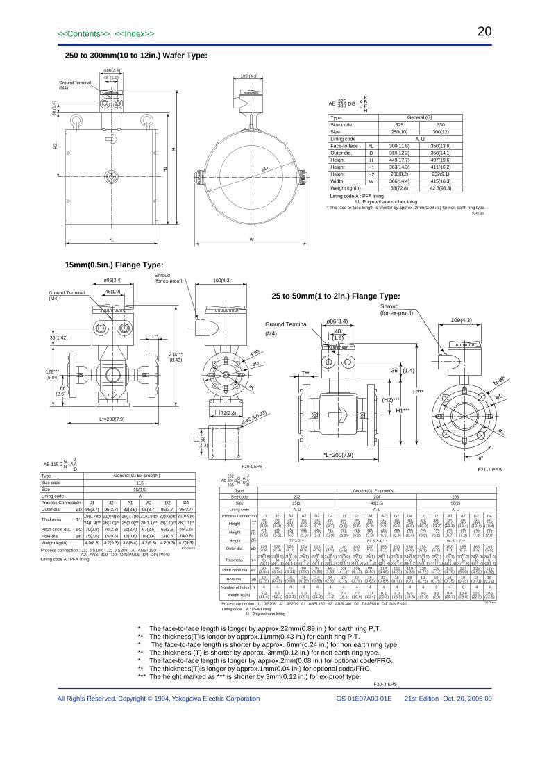
20<<Contents>> <<Index>>
GS 01E07A00-01E 21st Edition Oct. 20, 2005-00All Rights Reserved. Copyright © 1994, Yokogawa Electric Corporation
15mm(0.5in.) Flange Type:
25 to 50mm(1 to 2in.) Flange Type:
128***(5.04)
214***(8.43)
36(1.42) T**
66(2.6)
ø86(3.4)
48(1.9)
109(4.3)
Ground Terminal(M4)
L*=200(7.9)
58(2.3)
4-ø5.8(0.23)
4-øh
øD
72(2.8)
øC
Shroud(for ex-proof)
F20-1.EPSF21-1.EPS
H***
H1***
*L=200(7.9)
(H2)***
36 (1.4)T**
ø86(3.4)
48(1.9)
Ground Terminal
(M4)
109(4.3)
øD
øC
N-øh
Shroud(for ex-proof)
250 to 300mm(10 to 12in.) Wafer Type:
D
W
109 (4.3)
*L
H1
HH2
86(3.4)
48 (1.9)
36 (
1.4)
Ground Terminal(M4)
A, U
325250(10)
300(11.8)310(12.2)449(17.7)363(14.3)208(8.2)366(14.4)33(72.8)
330300(12)
350(13.8)358(14.1)497(19.6)411(16.2)232(9.1)415(16.3)42.3(93.3)
AE DG K
A BU E
H
325330 -
TypeSize codeSizeLining codeFace-to-faceOuter dia.HeightHeightHeightWidthWeight kg (lb)
*LDH
H1H2W
Lining code A : PFA lining U : Polyurethane rubber lining
General (G)
* The face-to-face length is shorter by approx. 2mm(0.08 in.) for non earth ring type.SD4b.eps
* The face-to-face length is longer by approx.22mm(0.89 in.) for earth ring P,T.** The thickness(T)is longer by approx.11mm(0.43 in.) for earth ring P,T.* The face-to-face length is shorter by approx. 6mm(o.24 in.) for non earth ring type.** The thickness (T) is shorter by approx. 3mm(0.12 in.) for non earth ring type.* The face-to-face length is longer by approx.2mm(0.08 in.) for optional code/FRG.** The thickness(T)is longer by approx.1mm(0.04 in.) for optional code/FRG.*** The height marked as *** is shorter by 3mm(0.12 in.) for ex-proof type.
F20-3.EPS
General(G), Ex-proof(N)
F21-2.eps
AE DGN
AU
JAD
202204205
-
Weight kg(lb)
Type
Size code
Size
Lining code
Process Connection
202
25(1)
A, U
204
40(1.5)
A, U
205
50(2)
A, U
Outer dia.
Number of holes N
Thickness T**
Lining code A : PFA LiningU : Polyurethane lining
Process connection : J1 ; JIS10K J2 ; JIS20K A1 ; ANSI 150 A2 ; ANSI 300 D2 ; DIN PN16 D4 ; DIN PN40
J1***226
(8.9)
**21(0.8)to
26(1)
***H
***H1
***H2
***140(5.5)
125(4.9)
90(3.54)
19(0.75)
4
5.2(11.4)
J2 A1 A2 D2 D4***226
(8.9)
**23(0.9)to
28(1.1)
***140(5.5)
125(4.9)
90(3.54)
19(0.75)
4
5.5(12.1)
***217(8.5)
**21(0.8)to
28(1.1)
***131(5.2)
108(4.3)
79(3.11)
16(0.63)
4
4.6(10.1)
***225(8.9)
**25(1)to
31(1.2)
***139(5.5)
124(4.9)
89(3.50)
19(0.75)
4
5.6(12.3)
***221(8.7)
**22(0.9)to
28(1.1)
***135(5.3)
115(4.5)
85(3.35)
14(0.55)
4
5.1(11.2)
***221(8.7)
**24(0.9)to
30(1.2)
***135(5.3)
115(4.5)
85(3.35)
14(0.55)
4
5.1(11.2)
***244(9.6)
**23(0.9)to
28(1.1)
***158(6.2)
140(5.5)
105(4.13)
19(0.75)
4
7.4(16.3)
77(3.0)***
J2 A1 A2 D2 D4***244
(9.6)
**25(1)to
30(1.2)
***158(6.2)
140(5.5)
105(4.13)
19(0.75)
4
7.7(16.9)
***237(9.3)
**25(1)to
31(1.2)
***151(5.9)
127(5.0)
99(3.90)
16(0.63)
4
7.0(15.4)
***251(9.9)
**28(1.1)to
34(1.3)
***165(6.5)
155(6.1)
114(4.49)
22(0.87)
4
9.2(20.2)
***249(9.8)
**22(0.9)to
28(1.1)
***163(6.4)
150(5.9)
110(4.33)
18(0.71)
4
8.0(18.5)
***249(9.8)
**24(0.9)to
30(1.2)
***163(6.4)
150(5.9)
110(4.33)
18(0.71)
4
8.0(18.5)
87.5(3.4)***
J1***258
(10.2)
**23(0.9)to
29(1.1)
***172(6.8)
155(6.1)
120(4.72)
19(0.75)
4
9.0(19.8)
J2 A1 A2 D2 D4***258
(10.2)
**25(1)to
31(1.2)
***172(6.8)
155(6.1)
120(4.72)
19(0.75)
8
9.1(20)
***257(10.1)
**26(1)to
33(1.3)
***171(6.7)
152(6.0)
121(4.76)
19(0.75)
4
9.4(20.7)
***263(10.4)
**30(1.2)to
37(1.5)
***177(7.0)
165(6.5)
127(5.00)
19(0.75)
8
10.8(23.8)
***263(10.4)
**24(0.9)to
30(1.2)
***177(7.0)
165(6.5)
125(4.92)
18(0.71)
4
10.2(22.5)
***263(10.4)
**26(1.0)to
33(1.3)
***177(7.0)
165(6.5)
125(4.92)
18(0.71)
4
10.2(22.5)
94.5(3.7)***
J1
Pitch circle dia.
Hole dia.
øC
øh
Height
Height
Height
øD
øD
T**
øC
øh
15(0.5)A
J1
95(3.7)
19(0.7)to
24(0.9)**
70(2.8)
15(0.6)
4.0(8.8)
J2
95(3.7)
21(0.8)to
26(1.0)**
70(2.8)
15(0.6)
4.2(9.3)
A1
89(3.5)
18(0.7)to
25(1.0)**
61(2.4)
16(0.6)
3.8(8.4)
A2
95(3.7)
21(0.8)to
28(1.1)**
67(2.6)
16(0.6)
4.2(9.3)
D2
95(3.7)
20(0.8)to
26(1.0)**
65(2.6)
14(0.6)
4.2(9.3)
Process connection : J1; JIS10K J2; JIS20K A; ANSI 150 A2; ANSI 300 D2; DIN PN16 D4; DIN PN40Lining code A : PFA lining
115
AE DGN A
JAD
115 -
Type
Size code
Size
Lining code
Process Connection
Outer dia.
Thickness
Pitch circle dia.
Hole dia.
Weight kg(lb)
General(G) Ex-proof(N)
D4
95(3.7)
22(0.9)to
28(1.1)**
65(2.6)
14(0.6)
4.2(9.3)F20-2.EPS
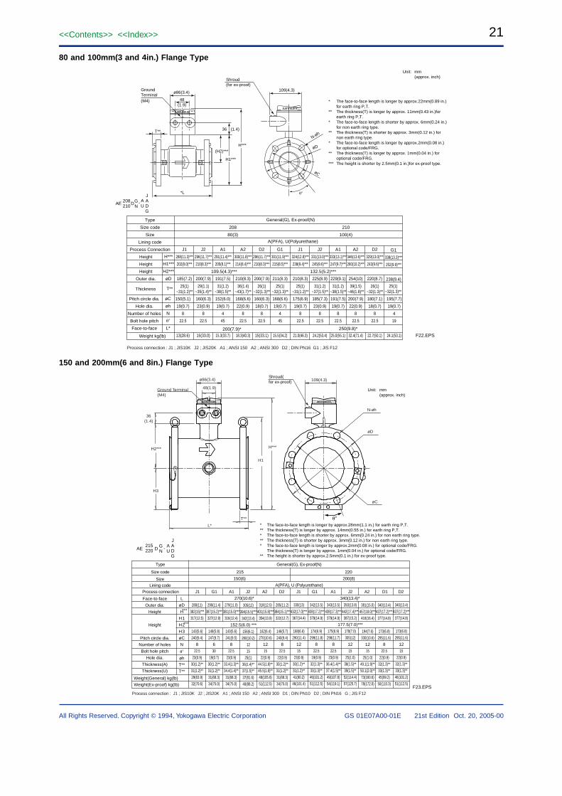
21<<Contents>> <<Index>>
All Rights Reserved. Copyright © 1994, Yokogawa Electric Corporation GS 01E07A00-01E 21st Edition Oct. 20, 2005-00
80 and 100mm(3 and 4in.) Flange Type
F22.EPS
Unit: mm(approx. inch)
H***
H1***
*L
(H2)***
36 (1.4)T**
ø86(3.4)
48(1.9)
GroundTerminal(M4)
109(4.3)
øD
øC
N-øh
Shroud(for ex-proof)
J1
288(11.3)***
202(8.0)***
185(7.2)
150(5.1)
19(0.7)
8
22.5
13(28.6)
25(1)~31(1.2)**
J2
296(11.7)***
210(8.3)***
200(7.9)
160(6.3)
23(0.9)
8
22.5
15(33.0)
29(1.1)~35(1.4)**
A1
291(11.4)***
205(8.1)***
191(7.5)
152(6.0)
19(0.7)
4
45
15.3(33.7)
31(1.2)~38(1.5)**
A2
300(11.8)***
214(8.4)***
210(8.3)
168(6.6)
22(0.9)
8
22.5
18.3(40.3)
36(1.4)~43(1.7)**
D2
296(11.7)***
210(8.3)***
200(7.9)
160(6.3)
18(0.7)
8
22.5
15(33.1)
26(1)~32(1.3)**
G1
301(11.9)***
215(8.5)***
211(8.3)
168(6.6)
19(0.7)
4
45
15.5(34.2)
25(1)~32(1.3)**
General(G), Ex-proof(N)
AE DGN
AU
JADG
208210
-
Weight kg(lb)
Type
Size code
Size
Lining code
Process Connection
208
80(3)
Height
Height
Height
Outer dia.
H***
H1***
H2***
øD
Pitch circle dia.
Hole dia.
Number of holes
Bolt hole pitch
Face-to-face
øC
øh
N
L*
Thickness T**
Process connection : J1 ; JIS10K J2 ; JIS20K A1 ; ANSI 150 A2 ; ANSI 300 D2 ; DIN PN16 G1 ; JIS F12
109.5(4.3)***
200(7.9)*
J1
324(12.8)***
238(9.4)***
210(8.3)
175(6.9)
19(0.7)
8
22.5
21.0(46.3)
25(1)~31(1.2)**
J2
331(13.0)***
245(9.6)***
225(8.9)
185(7.3)
23(0.9)
8
22.5
24.2(53.4)
31(1.2)~37(1.5)**
A1
333(13.1)***
247(9.7)***
229(9.1)
191(7.5)
19(0.7)
8
22.5
25.0(55.1)
31(1.2)~38(1.5)**
A2
346(13.6)***
260(10.2)***
254(10)
200(7.9)
22(0.9)
8
22.5
32.4(71.4)
39(1.5)~46(1.8)**
D2
329(13.0)***
243(9.6)***
220(8.7)
180(7.1)
18(0.7)
8
22.5
22.7(50.1)
26(1)~32(1.3)**
G1
338(13.3)***
252(9.9)***
238(9.4)
195(7.7)
19(0.7)
4
19
24.1(53.1)
25(1)~32(1.3)**
210
100(4)
132.5(5.2)***
250(9.8)*
* The face-to-face length is longer by approx.22mm(0.89 in.) for earth ring P,T.
** The thickness(T) is longer by approx. 11mm(0.43 in.)for earth ring P,T.
* The face-to-face length is shorter by approx. 6mm(0.24 in.) for non earth ring type.
** The thickness(T) is shorter by approx. 3mm(0.12 in.) for non earth ring type.
* The face-to-face length is longer by approx.2mm(0.08 in.) for optional code/FRG.
** The thickness(T) is longer by approx. 1mm(0.04 in.) for optional code/FRG.
*** The height is shorter by 2.5mm(0.1 in.)for ex-proof type.
A(PFA), U(Polyurethane)
150 and 200mm(6 and 8in.) Flange Type
* The face-to-face length is longer by approx.28mm(1.1 in.) for earth ring P,T.** The thickness(T) is longer by approx. 14mm(0.55 in.) for earth ring P,T.* The face-to-face length is shorter by approx. 6mm(0.24 in.) for non earth ring type.** The thickness(T) is shorter by approx. 3mm(0.12 in.) for non earth ring type.* The face-to-face length is longer by approx.2mm(0.08 in.) for optional code/FRG.
The thickness(T) is longer by approx. 1mm(0.04 in.) for optional code/FRG.** The height is shorter by approx.2.5mm(0.1 in.) for ex-proof type.
Unit: mm(approx. inch)
F23.EPS
ø86(3.4)
48(1.9)
109(4.3)
H1
H***
Ground Terminal(M4)
L*
H2***
36(1.4)
øD
N-øh
øC
T**
H3
Shroud(for ex-proof)
Face-to-face
Outer dia.
Height
Height
Pitch circle dia.
Number of holes
Bolt hole pitch
Hole dia.
Thickness(A)
Thickness(U)
L
øD
H
H1
H2
H3
øC
N
øh
T**
T**
Process connection
Size
J1 G1 A1 J2 A2 D2 J1 G1 A1 J2 A2 D1 D2
270(10.6)* 340(13.4)*
150(6) 200(8)
Lining code A(PFA), U (Polyurethane)
Weight(General) kg(lb)
Weight(Ex-proof) kg(lb)
Type General(G), Ex-proof(N)
Size code 215 220
AE D GN
AU
JADG
215220 -
280(11)
382(15)***
317(12.5)
143(5.6)
240(9.4)
8
22.5
23(0.9)
30(1.2)**
31(1.2)**
29(63.9)
32(70.6)
290(11.4)
387(15.2)***
327(12.9)
148(5.8)
247(9.7)
6
30
19(0.7)
30(1.2)**
31(1.2)**
31(68.3)
34(75.0)
279(11.0)
381(15.0)***
316(12.4)
143(5.6)
241(9.5)
8
22.5
23(0.9)
33.4(1.3)**
34.4(1.4)**
31(68.3)
34(75.0)
305(12)
394(15.5)***
342(13.4)
152.5(6.0) ***
156(6.1)
260(10.2)
12
15
25(1)
36(1.4)**
37(1.5)**
37(81.6)
40(88.2)
318(12.5)
401(15.8)***
354(13.9)
162(6.4)
270(10.6)
12
15
22(0.9)
44.5(1.8)**
45.5(1.8)**
48(105.8)
51(112.5)
285(11.2)
384(15.1)***
322(12.7)
146(5.7)
240(9.4)
8
22.5
22(0.9)
30(1.2)**
31(1.2)**
31(68.3)
34(75.0)
330(13)
432(17.0)***
367(14.4)
168(6.6)
290(11.4)
12
15
23(0.9)
30(1.2)**
31(1.2)**
41(90.2)
46(101.4)
342(13.5)
438(17.2)***
379(14.9)
174(6.9)
299(11.8)
8
22.5
19(0.9)
32(1.3)**
33(1.3)**
46(101.2)
51(112.5)
343(13.5)
438(17.3)***
379(14.9)
175(6.9)
298(11.7)
8
22.5
23(0.9)
36.4(1.4)**
37.4(1.5)**
49(107.8)
54(119.1)
350(13.8)
442(17.4)***
387(15.2)
177.5(7.0)***
178(7.0)
305(12)
12
15
25(1.0)
38(1.5)**
39(1.5)**
52(114.4)
57(125.7)
381(15.0)
457(18.0)***
418(16.4)
194(7.6)
330(10.6)
12
15
25(1.0)
49.1(1.9)**
50.1(2.0)**
73(160.6)
78(172.0)
340(13.4)
437(17.2)***
377(14.8)
173(6.8)
295(11.6)
8
22.5
22(0.9)
32(1.3)**
33(1.3)**
45(99.2)
50(110.3)
340(13.4)
437(17.2)***
377(14.8)
173(6.8)
295(11.6)
12
15
22(0.9)
32(1.3)**
33(1.3)**
46(101.2)
51(112.5)
Process connection : J1 ; JIS10K J2 ; JIS20K A1 ; ANSI 150 A2 ; ANSI 300 D1 ; DIN PN10 D2 ; DIN PN16 G ; JIS F12
***
***
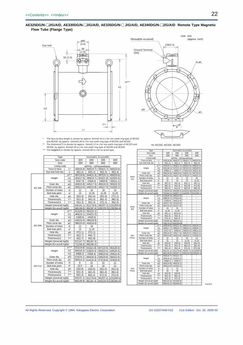
22<<Contents>> <<Index>>
GS 01E07A00-01E 21st Edition Oct. 20, 2005-00All Rights Reserved. Copyright © 1994, Yokogawa Electric Corporation
AE325DG/N-J/G/A/D, AE330DG/N-J/G/A/D, AE335DG/N- J/G/A/D, AE340DG/N-J/G/A/D Remote Type MagneticFlow Tube (Flange Type)
Unit: mm(approx. inch)
F24.EPS
ø86(3.4)
48(1.9)
109(4.3)
H1
H***
Ground Terminal(M4)
L*
H2 øD
N-øh
øC
T**
Eye bolt
50 (2.0)
for AE330, AE335, AE340
Shroud(for ex-proof)
JIS 10K
JIS 20K
JIS F12
H***H1H2øDøCNøhT**T**
L*e
H***H1H2øDøCNøhT**T**
H***H1H2øDøCNøhT**T**
General(G), Ex-proof(N)
A(PFA) , U(Polyurethane)
––––––––––––
––––––––––––
Height
Outer dia.Pitch circle dia.
Number of holesBolt hole pitch
Hole dia.Thickness(A)Thickness(U)
Weight (General) kg(lb) Weight (Ex-proof) kg(lb)
TypeSize code
SizeLining code
Face-to-faceEye bolt hole dia.
Height
Outer dia.Pitch circle dia.
Number of holesBolt hole pitch
Hole dia.Thickness(A)Thickness(U)
Weight (General) kg(lb) Weight (Ex-proof) kg(lb)
Height
Outer dia.Pitch circle dia.
Number of holesBolt hole pitch
Hole dia.Thickness(A)Thickness(U)
Weight (General) kg(lb) Weight (Ex-proof) kg(lb)
325250
330300
335350
340400
430(16.9)30(1.2)
497(19.6)454(17.9)203(7.9)
400(15.8)355(14.0)
1215
25(1.0)32(1.3)33(1.3)
64(141.1)68(149.9)
500(19.7)30(1.2)
544(21.4)499(19.7)226(9.0)
445(17.5)400(15.8)
1611.25
25(1.0)34(1.3)35(1.4)
81(178.6)85(187.4)
550(21.7)35(1.4)
587(23.1)553(21.8)248(9.8)
490(19.3)445(17.5)
1611.25
25(1.0)36(1.4)37(1.4)
94(207.2)100(220.5)
600(23.6)35(1.4)
650(25.6)623(24.5)283(11.1)560(22.0)510(20.1)
1611.25
27(1.1)38(1.5)39(1.5)
122(269.0)129(284.4)
512(20.2)484(19.1)218(8.6)
430(16.9)380(15.0)
1215
27(1.1)42(1.7)43(1.7)
67(147.7)71(156.5)
561(22.1)534(21.0)243(9.6)
480(18.9)430(16.9)
1611.25
27(1.1)44(1.7)45(1.8)
85(187.4)89(196.2)
502(19.8)464(18.3)208(8.2)
410(16.1)360(14.2)
822.5
23(0.9)32(1.3)33(1.3)
64(141.1)68(149.9)
553(21.8)518(20.4)235(9.3)
464(18.3)414(16.3)
1018
23(0.9)34(1.3)35(1.4)
81(178.6)85(187.4)
607(23.9)593(23.4)268(10.6)530(20.9)472(18.6)
1018
25(1.0)36(1.4)37(1.5)
94(207.2)100(220.5)
661(26.0)645(25.4)294(11.6)582(22.9)524(20.6)
1215
25(1.0)36(1.4)37(1.5)
122(269.0)129(284.4)
* The face-to-face length is shorter by approx. 6mm(0.24 in.) for non earth ring type of AE325 and AE330, by approx. 10mm(0.39 in.) for non earth ring type of AE335 and AE340.
** The thickness(T) is shorter by approx. 3mm(0.12 in.) for non earth ring type of AE325 and AE330, by approx. 5mm(0.20 in.) for non earth ring type of AE335 and AE340.
*** The height(H) is shorter by approx. 2mm(0.08 in.) for ex-proof type.
H***H1H2øDøCNøhT**T**
L*e
H***H1H2øDøCNøhT**T**
H***H1H2øDøCNøhT**T**
General(G), Ex-proof(N)
A(PFA) , U(Polyurethane)
––––––––––––
––––––––––––
––––––––––––
––––––––––––
Height
Outer dia.Pitch circle dia.
Number of holesBolt hole pitch
Hole dia.Thickness(A)Thickness(U)
Weight (General) kg(lb) Weight (Ex-proof) kg(lb)
TypeSize code
SizeLining code
Face-to-faceEye bolt hole dia.
Height
Outer dia.Pitch circle dia.
Number of holesBolt hole pitch
Hole dia.Thickness(A)Thickness(U)
Weight (General) kg(lb) Weight (Ex-proof) kg(lb)
Height
Outer dia.Pitch circle dia.
Number of holesBolt hole pitch
Hole dia.Thickness(A)Thickness(U)
Weight (General) kg(lb) Weight (Ex-proof) kg(lb)
325250
330300
335350
340400
430(16.9)30(1.2)
500(19.7)461(18.1)206(8.1)406(16.0)362(14.3)
1215
26(1.0)38(1.5)39(1.5)
70(154.3)74(163.1)
500(19.7)30(1.2)
563(22.2)537(21.1)245(9.7)483(19.0)432(17.0)
1215
26(1.0)40(1.6)41(1.6)
90(198.4)94(207.2)
550(21.7)35(1.4)
609(24.0)597(23.5)270(10.6)533(21.0)476(18.7)
1215
29(1.1)45(1.8)46(1.8)
110(242.5)116(255.7)
600(23.6)35(1.4)
668(26.3)660(26.0)302(11.9)597(23.5)540(21.3)
1611.25
29(1.1)47(1.9)48(1.9)
145(319.7)152(335.1)
519(20.4)499(19.7)225(8.9)445(17.5)387(15.2)
1611.25
29(1.1)56(2.3)57(2.2)
75(165.4)79(174.2)
582(22.9)575(22.6)264(10.4)521(20.5)451(17.8)
1611.25
32(12.6)59(2.3)60(2.4)
98(216.1)102(224.9)
495(19.5)449(17.7)201(7.9)395(15.6)350(13.8)
1215
22(0.9)34(1.3)35(1.4)
64(141.1)68(149.9)
544(21.4)499(19.7)226(9.0)445(17.5)400(15.8)
1215
22(0.9)34(1.3)35(1.4)
81(178.6)85(187.4)
595(23.4)568(22.4)256(10.0)505(20.0)460(18.1)
1611.25
22(0.9)36(1.4)37(1.5)
94(207.2)100(220.5)
652(25.7)628(24.7)286(11.3)565(22.2)515(20.3)
1611.25
26(1.0)36(1.4)37(1.5))
122(269.0)129(284.4)
ANSI150
ANSI300
DINPN10
H***H1H2øDøCNøhT**T**
Height
Outer dia.Pitch circle dia.
Number of holesBolt hole pitch
Hole dia.Thickness(A)Thickness(U)
Weight (General) kg(lb) Weight (Ex-proof) kg(lb)
500(19.7)459(18.1)206(8.1)405(15.9)355(14.0)
1215
22(0.9)34(1.3)35(1.4)
65(143.3)69(152.1)
551(21.7)514(20.2)233(9.2)460(18.1)410(16.1)
1215
22(0.9)36(1.4)37(1.5)
82(180.8)86(189.6)
DINPN16
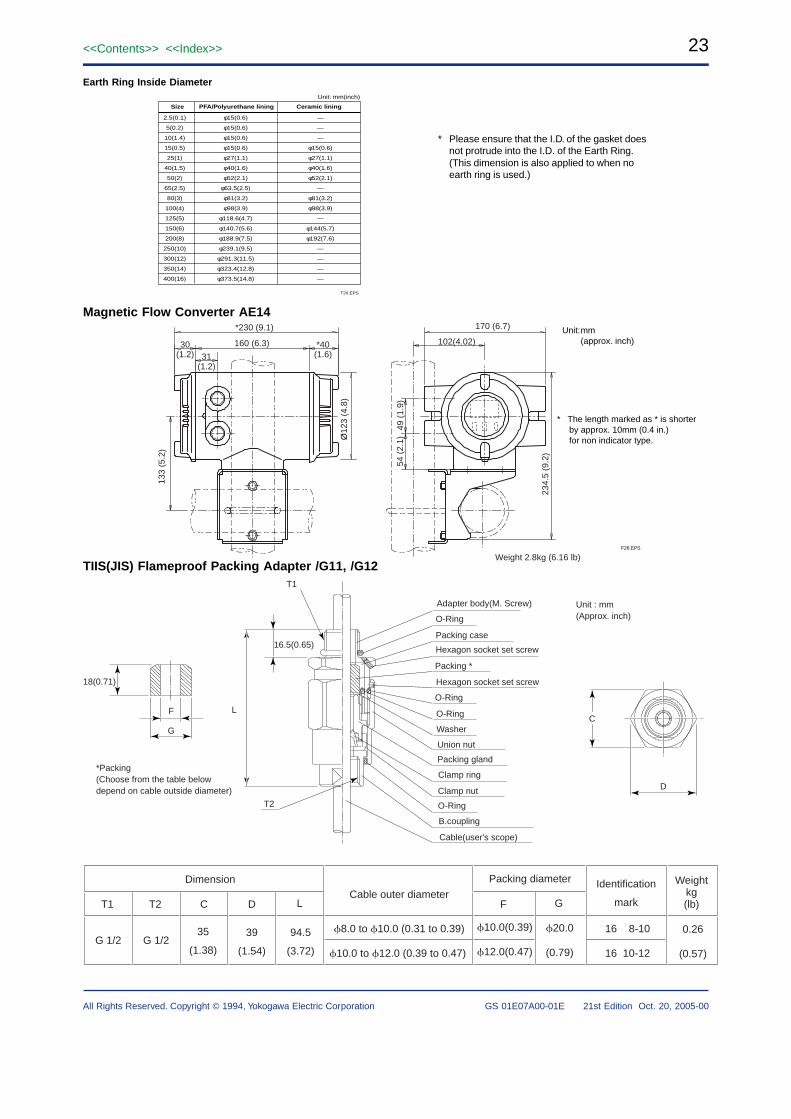
23<<Contents>> <<Index>>
All Rights Reserved. Copyright © 1994, Yokogawa Electric Corporation GS 01E07A00-01E 21st Edition Oct. 20, 2005-00
Earth Ring Inside Diameter
Size PFA/Polyurethane lining Ceramic lining
2.5(0.1)
5(0.2)
10(1.4)
15(0.5)
25(1)
40(1.5)
50(2)
65(2.5)
80(3)
100(4)
125(5)
150(6)
200(8)
250(10)
300(12)
350(14)
400(16)
φ15(0.6)
φ15(0.6)
φ15(0.6)
φ15(0.6)
φ27(1.1)
φ40(1.6)
φ52(2.1)
φ63.5(2.5)
φ81(3.2)
φ98(3.9)
φ118.6(4.7)
φ140.7(5.6)
φ188.9(7.5)
φ239.1(9.5)
φ291.3(11.5)
φ323.4(12.8)
φ373.5(14.8)
—
—
—
φ15(0.6)
φ27(1.1)
φ40(1.6)
φ52(2.1)
—
φ81(3.2)
φ98(3.9)
—
φ144(5.7)
φ192(7.6)
—
—
—
—
T20.EPS
Unit: mm(inch)
Magnetic Flow Converter AE14
TIIS(JIS) Flameproof Packing Adapter /G11, /G12
0.26
(0.57)
8.0 to 10.0 (0.31 to 0.39)
10.0 to 12.0 (0.39 to 0.47)
16 8-10
16 10-12
Identification
mark
Weightkg(lb)
Packing diameter
Cable outer diameterT1 T2 C D L
Dimension
G 1/2 G 1/235
(1.38)
39
(1.54)
94.5
(3.72)
10.0(0.39)
12.0(0.47)
20.0
(0.79)
F G
* Please ensure that the I.D. of the gasket doesnot protrude into the I.D. of the Earth Ring.(This dimension is also applied to when noearth ring is used.)
T1
T2
L
18(0.71)
G
F
D
C
16.5(0.65)
*Packing(Choose from the table belowdepend on cable outside diameter)
Unit : mm (Approx. inch)
Adapter body(M. Screw)
Packing case
Hexagon socket set screw
O-Ring
Packing *
O-Ring
O-Ring
Washer
Union nut
Packing gland
Clamp ring
Clamp nut
O-Ring
B.coupling
Cable(user's scope)
Hexagon socket set screw
* The length marked as * is shorter by approx. 10mm (0.4 in.) for non indicator type.
F26.EPS
Unit:mm(approx. inch)
*230 (9.1)
160 (6.3) *40(1.6)31
(1.2)
133
(5.2
)
Ø12
3 (4
.8)
170 (6.7)
49 (
1.9)
54 (
2.1)
234.
5 (9
.2)
102(4.02)30(1.2)
Weight 2.8kg (6.16 lb)
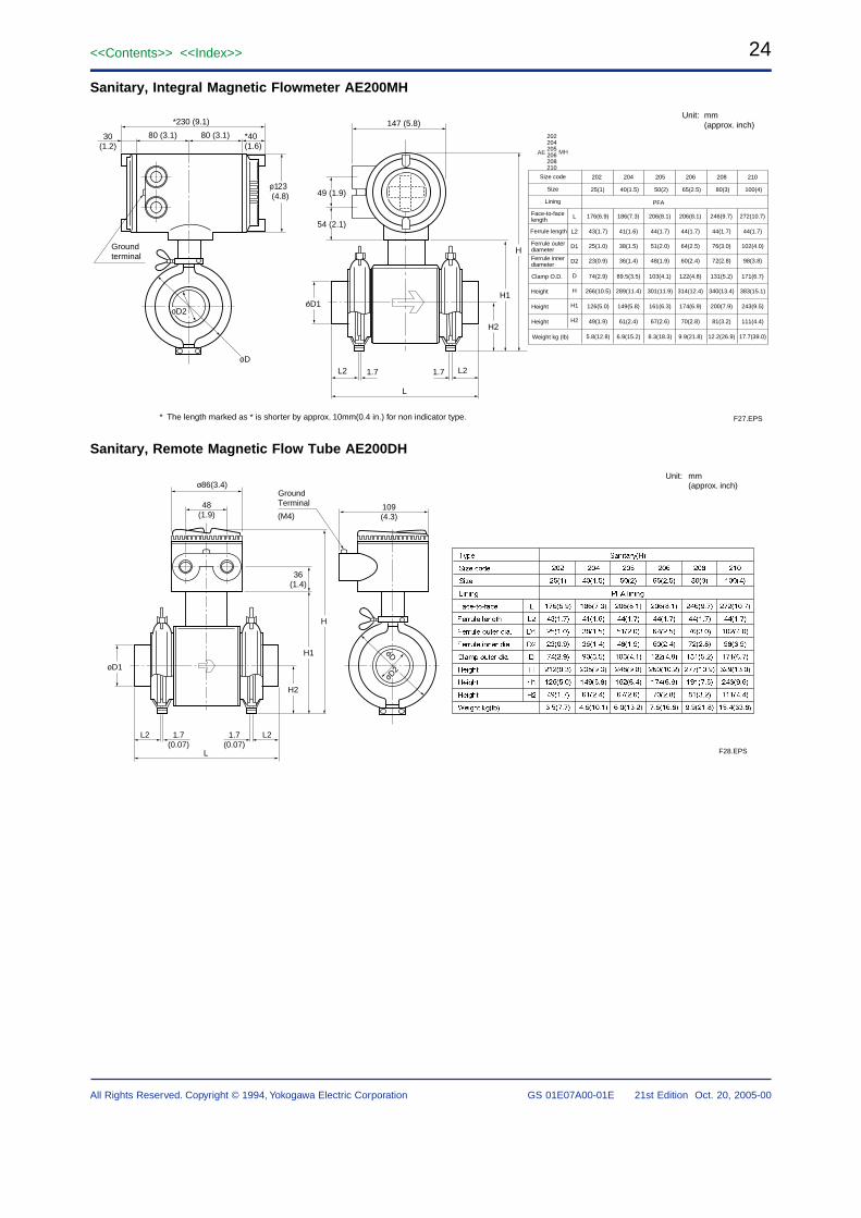
24<<Contents>> <<Index>>
GS 01E07A00-01E 21st Edition Oct. 20, 2005-00All Rights Reserved. Copyright © 1994, Yokogawa Electric Corporation
Sanitary, Integral Magnetic Flowmeter AE200MH
* The length marked as * is shorter by approx. 10mm(0.4 in.) for non indicator type.
Unit: mm(approx. inch)
F27.EPS
oD
30(1.2)
80 (3.1) 80 (3.1)147 (5.8)
o123 (4.8)
*230 (9.1)
*40(1.6)
oD1
L2 L21.7 1.7
H2
H1
H
L
49 (1.9)
54 (2.1)
oD2
Groundterminal
Size code
Size
Lining
Face-to-facelength
Height
202
25(1)
204
40(1.5)
205
50(2)
208
80(3)
210
100(4)
Ferrule length
Clamp O.D.
L
L2
D1
D2
D
H
H1
H2
Weight kg (lb)
176(6.9)
43(1.7)
25(1.0)
23(0.9)
74(2.9)
266(10.5)
126(5.0)
49(1.9)
5.8(12.8)
186(7.3)
41(1.6)
38(1.5)
36(1.4)
89.5(3.5)
289(11.4)
149(5.8)
61(2.4)
6.9(15.2)
206(8.1)
44(1.7)
51(2.0)
48(1.9)
103(4.1)
301(11.9)
161(6.3)
67(2.6)
8.3(18.3)
246(9.7)
44(1.7)
76(3.0)
72(2.8)
131(5.2)
340(13.4)
200(7.9)
81(3.2)
12.2(26.9)
206
65(2.5)
206(8.1)
44(1.7)
64(2.5)
60(2.4)
122(4.8)
314(12.4)
174(6.9)
70(2.8)
9.9(21.8)
272(10.7)
44(1.7)
102(4.0)
98(3.8)
171(6.7)
383(15.1)
243(9.5)
111(4.4)
17.7(39.0)
PFA
Height
Height
Ferrule innerdiameter
Ferrule outerdiameter
202204205206208210
AE MH
Sanitary, Remote Magnetic Flow Tube AE200DH
Unit: mm(approx. inch)
F28.EPS
o86(3.4)
48(1.9)
oD1
L2 L21.7(0.07)
1.7(0.07)
H2
H1
H
36(1.4)
GroundTerminal
(M4)109(4.3)
oD
L
oD2
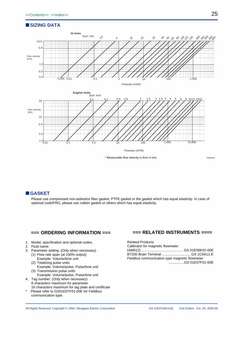
25<<Contents>> <<Index>>
All Rights Reserved. Copyright © 1994, Yokogawa Electric Corporation GS 01E07A00-01E 21st Edition Oct. 20, 2005-00
=== ORDERING INFORMATION ===
1. Model, specification and optional codes.2. Fluid name.3. Parameter setting. (Only when necessary)
(1) Flow rate span (at 100% output)Example: Volume/time unit
(2) Totalizing pulse unitsExample: Volume/pulse, Pulse/time unit
(3) Transmission pulse unitsExample: Volume/pulse, Pulse/time unit
4. Tag number. (Only when necessary)8 characters maximum for parameter16 characters maximum for tag plate and certificate
* Please refer to GS01E07F01-00E for Fieldbuscommunication type.
=== RELATED INSTRUMENTS ====
Related ProductsCalibrator for magnetic flowmeter(AM012) ........................................... GS 01E06K02-00EBT200 Brain Terminal .............................. GS 1C0A11-EFieldbus communication type magnetic flowmeter ................GS 01E07F01-00E
GASKETPlease use compressed non-asbestos fiber gasket, PTFE gasket or the gasket which has equal elasticity. In case ofoptional code/FRG, please use rubber gasket or others which has equal elasticity.
SIZING DATA
15 25 6540 50 80 100
125
150
200
250
300
350Size: mm
400
Flow velocity(m/s)
0.5
1.0
5.0
10.0
0.3
Flow velocity(ft/s)
Flowrate (GPM)
33
5.0
1.0
10
2.0
1
SI Units
105
1 1,000100100.10.010.005
10,0001.0 1,00010010
Size (inch)
0.10.01
0.5 21.5 2.51 3 4 5 6 12108 14160.40.20.1
English Units
Flowrate (m3/h)
Size: inch
2.5
F29.EPS* Measurable flow velocity is from 0 m/s.