Embed Size (px)
Citation preview
GeneralSpecifications
<<Contents>> <<Index>>
MX100/MW100 Specifications
GS 04M10A01-01E
GS 04M10A01-01E©Copyright Sep. 2007
12th Edition Jan. 2017 (YK)
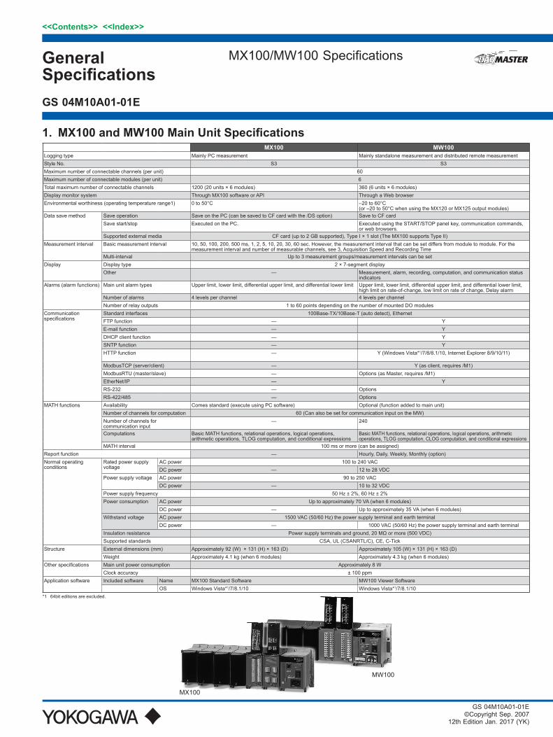
MX100 MW100Logging type Mainly PC measurement Mainly standalone measurement and distributed remote measurementStyle No. S3 S3Maximum number of connectable channels (per unit) 60Maximum number of connectable modules (per unit) 6Total maximum number of connectable channels 1200 (20 units × 6 modules) 360 (6 units × 6 modules)Display monitor system Through MX100 software or API Through a Web browserEnvironmental worthiness (operating temperature range1) 0 to 50°C –20 to 60°C
(or –20 to 50°C when using the MX120 or MX125 output modules)Data save method Save operation Save on the PC (can be saved to CF card with the /DS option) Save to CF card
Save start/stop Executed on the PC. Executed using the START/STOP panel key, communication commands,or web browsers.
Supported external media CF card (up to 2 GB supported), Type I × 1 slot (The MX100 supports Type II)Measurement interval Basic measurement interval 10, 50, 100, 200, 500 ms, 1, 2, 5, 10, 20, 30, 60 sec. However, the measurement interval that can be set differs from module to module. For the
measurement interval and number of measurable channels, see 3, Acquisition Speed and Recording TimeMulti-interval Up to 3 measurement groups/measurement intervals can be set
Display Display type 2 × 7-segment displayOther — Measurement, alarm, recording, computation, and communication status
indicatorsAlarms (alarm functions) Main unit alarm types Upper limit, lower limit, differential upper limit, and differential lower limit Upper limit, lower limit, differential upper limit, and differential lower limit,
high limit on rate-of-change, low limit on rate of change, Delay alarm Number of alarms 4 levels per channel 4 levels per channelNumber of relay outputs 1 to 60 points depending on the number of mounted DO modules
Communication specifications
Standard interfaces 100Base-TX/10Base-T (auto detect), Ethernet FTP function — YE-mail function — YDHCP client function — YSNTP function — YHTTP function — Y (Windows Vista*1/7/8/8.1/10, Internet Explorer 8/9/10/11)
ModbusTCP (server/client) — Y (as client, requires /M1)ModbusRTU (master/slave) — Options (as Master, requires /M1) EtherNet/IP — YRS-232 — OptionsRS-422/485 — Options
MATH functions Availability Comes standard (execute using PC software) Optional (function added to main unit)Number of channels for computation 60 (Can also be set for communication input on the MW)Number of channels for communication input
— 240
Computations Basic MATH functions, relational operations, logical operations, arithmetic operations, TLOG computation, and conditional expressions
Basic MATH functions, relational operations, logical operations, arithmeticoperations, TLOG computation, CLOG computation, and conditional expressions
MATH interval 100 ms or more (can be assigned)Report function — Hourly, Daily, Weekly, Monthly (option)Normal operatingconditions
Rated power supplyvoltage
AC power 100 to 240 VACDC power — 12 to 28 VDC
Power supply voltage AC power 90 to 250 VACDC power — 10 to 32 VDC
Power supply frequency 50 Hz ± 2%, 60 Hz ± 2%Power consumption AC power Up to approximately 70 VA (when 6 modules)
DC power — Up to approximately 35 VA (when 6 modules)Withstand voltage AC power 1500 VAC (50/60 Hz) the power supply terminal and earth terminal
DC power — 1000 VAC (50/60 Hz) the power supply terminal and earth terminalInsulation resistance Power supply terminals and ground, 20 MΩ or more (500 VDC)Supported standards CSA, UL (CSANRTL/C), CE, C-Tick
Structure External dimensions (mm) Approximately 92 (W) × 131 (H) × 163 (D) Approximately 105 (W) × 131 (H) × 163 (D)Weight Approximately 4.1 kg (when 6 modules) Approximately 4.3 kg (when 6 modules)
Other specifications Main unit power consumption Approximately 8 WClock accuracy ± 100 ppm
Application software Included software Name MX100 Standard Software MW100 Viewer SoftwareOS Windows Vista*1/7/8.1/10 Windows Vista*1/7/8.1/10
*1 64bit editions are excluded.
1. MX100andMW100MainUnitSpecifications
MX100
MW100
2
All Rights Reserved. Copyright © 2007, Yokogawa Electric Corporation
<<Contents>> <<Index>>
GS 04M10A01-01E Jan. 10, 2017-00
4-CH, High-Speed Universal Input Module MX110-UNV-H04
2.Input/OutputModuleSpecifications 4-CH,High-SpeedUniversalInputModule
Module number MX110-UNV-H04Style number S1Number of inputs 4Measurement interval 10 ms (shortest)Types of measurement DC voltage, thermocouple, 3-wire RTD, DI (non-voltage
contact, level (5 V logic))A/D resolution ± 20000/± 6000Power consumption Approximately 3 WExternal dimensions (mm) Approximately 57 × 131 × 151
(including terminal cover) Terminal type Clamp, removable on each CH Applicable cable size 0.2 to 2.5 mm2 (AWG 24 to 12) Withstand voltage Between input
terminals3000 VACrms (50/60 Hz), for one minute
Between input terminals and ground
3700 VACrms (50/60 Hz), for one minute
Normal-mode voltage DCV, TC, DI (level) 1.2 times the range rating or less (50/60 Hz, peak value including signals)
RTD 100 Ω 50 mV peak RTD 10, 25, 50 Ω 10 mV peak
Normal-mode rejection ratio
For integral time of 16.67 ms or more, 40 dB or more (50/60 Hz ± 0.1%) 50/60 Hz not rejected when the integral time is 1.67 ms.
Common-mode voltage 600 VACrms (50/60 Hz), reinforced (double) insulation Common-mode rejection ratio
When the integral time is 16.67 ms or more, 120 dB or more
(50/60 Hz ±0.1%, 500 Ω unbalanced between minus measurement terminal and ground)When the integral time is 1.67 ms or more, 80 dB or
more Common-mode voltage between channels 250 VACrms (50/60 Hz), reinforced (double) insulation
•MeasurementRangesandAccuraciesThe accuracy applies to standard operating conditions: ambient temp: 23±2°C, ambient humidity: 55±10% RH, supply voltage: 90 to 250 VAC, power frequency: 50/60 Hz ±1%, warm-up time: at least 30 minutes, without adverse conditions such as vibrations.
Input Type Rated measurement range
Measurement accuracy integral time 16.67 ms or
more Measurement accuracy
integral time 1.67 ms
DC voltage
20 mV –20.000 to 20.000 mV ±(0.05% of rdg. + 5 digits) ±(0.1% of rdg. + 25 digits)60 mV –60.00 to 60.00 mV ±(0.05% of rdg.
+ 2 digits)
±(0.1% of rdg. + 10 digits)
200 mV –200.00 to 200.00 mV2 V –2.0000 to 2.0000 V ±(0.05% of rdg.+ 5 digits)6 V –6.000 to 6.000 V
±(0.05% of rdg. + 2 digits)20 V –20.000 to 20.000 V100 V –100.00 to 100.00 V
Thermocouple (excludes RJC accuracy, when burnout is OFF)
R *1
0.0 to 1760.0°C ±(0.05% of rdg. + 1°C)However, R, S:
0 to 100°C: ±3.7°C100 to 300°C: ±1.5°C
B:400 to 600C: ±2°CLess than 400°C:
accuracy not guaranteed
±(0.1% of rdg. + 4°C)However, R,S:
0 to 100°C: ±10°C100 to 300°C: ±5°C
B:400 to 600°C: ±7°C
Less than 400°C: accuracy not guarantee
S *1
B *1 0.0 to 1820.0°C
K *1 –200.0 to 1370.0°C
±(0.05% of rdg. + 0.7°C)However,
–200 to –100°C: ±(0.05% of rdg.
+1°C)
±(0.1% of rdg. + 3.5°C)However,
–200 to –100°C: ±(0.1% of rdg.
+ 6°C)*10
E *1 –200.0 to 800.0°C±(0.05% of rdg. + 0.5°C)
However, J, L:–200 to –100°C:
±(0.05% of rdg. + 0.7°C)
±(0.1% of rdg. + 2.5°C)However,
–200 to –100°C: ±(0.1% of rdg. + 5°C)
J *1 –200.0 to 1100.0°CT *1 –200.0 to 400.0°CL *2 –200.0 to 900.0°CU –200.0 to 400.0°C
N *3 0.0 to 1300.0°C ±(0.05% of rdg. + 0.7°C) ±(0.1% of rdg. + 3.5°C)
W *4 0.0 to 2315.0°C ±(0.05% of rdg. + 1°C) ±(0.1% of rdg. + 7°C)
KPvsAu7Fe 0.0 to 300.0 K ±(0.05% of rdg. + 0.7 K) ±(0.1% of rdg. + 3.5 K)
3-wire RTD (Mesurement current 1 mA)
Pt100 *5 –200.0 to 600.0°C
±(0.05% of rdg. + 0.3°C) ±(0.1% of rdg. + 1.5°C)
JPt100 *5 –200.0 to 550.0°CPt100 (high resolution) –140.00 to 150.00°C
JPt100 (high resolution) –140.00 to 150.00°C
Ni100 SAMA *6 –00.0 to 250.0°CNi100 DIN *6 –60.0 to 180.0°C
Ni120 *7 –70.0 to 200.0°C
3-wire RTD (Measurement current 2 mA)
Pt100 *5 –200.0 to 250.0°C
±(0.05% of rdg. + 0.3°C) ±(0.1% of rdg. + 1.5°C)
JPt100 *5 –200.0 to 250.0°CPt100 (high resolution) –140.00 to 150.00°C
JPt100 (high resolution) –140.00 to 150.00°C
Pt50 *5 –200.0 to 550.0°CCu10 GE *8 –200.0 to 300.0°C
±(0.1% of rdg. + 0.7°C) ±(0.2% of rdg. + 2.5°C)Cu10 L&N *8 –200.0 to 300.0°CCu10 WEED *8 –200.0 to 300.0°CCu10 BAILEY *8 –200.0 to 300.0°C
J263B 0.0 to 300.0 K ±(0.05% of rdg. + 0.3 K) ±(0.1% of rdg. + 1.5K)
DI Level Vth = 2.4 V Threshold level accuracy ±0.1 VNon-voltage contact 100 V or less: ON, 10 kV or more: OFF *9
*1 R, S, B, K, E, J, T: ANSI, IEC 584, DIN IEC 584, JIS C 1602-1995*2 L: Fe-CuNi, DIN43710/U: Cu-CuNi, DIN 43710*3 N: Nicrosil-Nisil, IEC 584, DIN IEC 584*4 W: W 5%RE-W 26%Re (Hoskins Mfg Co)*5 Pt50: JIS C 1604-1989, JIS C 1606-1989/Pt100: JIS C 1604-1997, IEC 751, DIN IEC 751/JPt100: JIS C 1604-1989, JIS
C 1606-1989*6 SAMA/DIN*7 McGRAW EDISON COMPANY*8 Guaranteed accuracy range Cu10 GE: –84.4 to 170.0°C/Cu10 L&N: –75.0 to 150.0°C/Cu10 WEED: –20.0 to 250.0°C
/Cu10 BAILEY: –20.0 to 250.0°C*9 To be determined at the measurement current of 1 mA and within the range of 2 V. The threshold level is
approximately 0.8 V.
*SpecialInputRanges(MX100canbeusedinMXLOGGER)Input Type Rated measurement
rangeMeasurement accuracy
integral time 16.67 ms or moreMeasurement accuracy
integral time 1.67 ms
Voltage60 mV 0.000 to 60.000 mV ±(0.05% of rdg. +20 digits) ±(0.1% of rdg. +100 digits)
1 V –1 .0000 to 1.0000 V ±(0.05% of rdg. +2 digits) ±(0.1% of rdg. +10 digits)6 V 0.0000 to 6.0000 V ±(0.05% of rdg. +20 digits) ±(0.1% of rdg. +100 digits)
Supported thermocouple: PLATINEL, PR40-20, NiNiMo, WRe3-25, W/WRe26, N (AWG14)Supported RTD: PT100 (high noise resistance), JPt (high noise resistance), Cu10 (at 20°C, a = 0.00392), Cu10 (at
20°C, a = 0.00393), Cu25 (at 0°C, a = 0.00425), Cu53 (at 0°C, a = 0.00426035), Cu100 (at 0°C, a = 0.00425), Pt25, Cu10 GE (high resolution), Cu10 L&N (high resolution), Cu10 WEED (high resolution), Cu10 BAILEY (high resolution)
also supports some of GOST ranges.
Measurement Interval 10 ms*1 50 ms 100 ms 200 ms 500 ms 1 s 2, 5,10, 20, 30,
60 s
Integration Time 1.67 ms 16.67 ms 20 ms Auto*2 36.67 ms 100 ms 200 ms
*1 When the measurement interval is 10 ms, measured values may fluctuate since power supply frequency noise is not rejected. In such cases, set the measurement interval to 50 ms or more.
*2 For DC power, set to 20 ms.
Reference junction compensation: Switch external/internal by channel, includes remote RJC functionReference junction compensation accuracy: When measuring temperature greater than or equal to 0°C and when the
temperature of the input terminal is balanced Type R, S, W: ±1°C Type K, J, E, T, N, L, U, XK GOST: ±0.5°C Type N(AWG14), PLATINEL, NiNiMo, WRe3-25, W/WRe26: ±1°CNote: The internal reference junction compensation is fixed to 0°C for type B and PR40-20
3<<Contents>> <<Index>>
All Rights Reserved. Copyright © 2007, Yokogawa Electric Corporation GS 04M10A01-01E Jan. 10, 2017-00
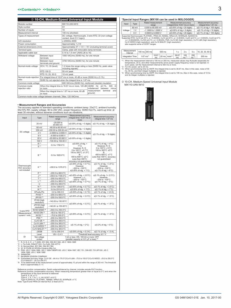
10-CH, Medium-Speed Universal Input Module MX110-UNV-M10
10-CH,Medium-SpeedUniversalInputModuleModule number MX110-UNV-M10Style number S1Number of inputs 10Measurement interval 100 ms (shortest)Types of measurement DC voltage, thermocouple, 3-wire RTD, DI (non-voltage
contact, level (5 V logic))A/D resolution ± 20000/± 6000Power consumption Approximately 1.2 WExternal dimensions (mm) Approximately 57 × 131 × 151 (including terminal cover)Terminal types Clamp, plate with removable clamp terminals Applicable cable size 0.14 to 1.5 mm2 (AWG 26 to 16)Withstand voltage Between input
terminals1000 VACrms (50/60 Hz), for one minute
Between input terminals and ground
3700 VACrms (50/60 Hz), for one minute
Normal-mode voltage DCV, TC, DI (level) 1.2 times the range rating or less (50/60 Hz, peak value including signals)
RTD 100 Ω 50 mV peakRTD 10, 25, 50 Ω 10 mV peak
Normal-mode rejection ratio
For integral time of 16.67 ms or more, 40 dB or more (50/60 Hz ± 0.1%)50/60 Hz not rejected when the integral time is 1.67 ms.
Common-mode voltage 600 VACrms (50/60 Hz), reinforced (double) insulationCommon-mode rejection ratio
When the integral time is 16.67 ms or more, 120 dB or more
(50/60 Hz ±0.1%, 500 Ω unbalanced between minus measurement terminal and ground)
When the integral time is 1.67 ms or more, 80 dB or more
Common-mode noise voltage between channels Max. 120 VACrms
•MeasurementRangesandAccuraciesThe accuracy applies to standard operating conditions: ambient temp: 23±2°C, ambient humidity: 55±10% RH, supply voltage: 90 to 250 VAC, power frequency: 50/60 Hz±1%, warm-up time: at least 30 minutes, without adverse conditions such as vibrations.
Input Type Rated measurement range
Measurement accuracy integral time 16.67 ms or
more Measurement accuracy
integral time 1.67 ms
DC voltage
20 mV –20.000 to 20.000 mV ±(0.05% of rdg. + 5 digits) ±(0.1% of rdg. + 25 digits)
60 mV –60.00 to 60.00 mV ±(0.05% of rdg. + 2 digits)
±(0.1% of rdg. + 10 digits)
200 mV –200.00 to 200.00 mV2 V –2.0000 to 2.0000 V ±(0.05% of rdg. + 5 digits)6 V –6.000 to 6.000 V
±(0.05% of rdg. + 2 digits)20 V –20.000 to 20.000 V100 V –100.00 to 100.00 V
Thermocouple RJC accuracy not included
R *1
0.0 to 1760.0°C ±(0.05% of rdg. + 1°C)
However, R, S:0 to 100°C: ±3.7°C
100 to 300°C: ±1.5°CB:
400 to 600°C: ±2°CLess than 400°C:
accuracy not guaranteed
±(0.1% of rdg. + 4°C)However, R, S:
0 to 100°C: ±10°C100 to 300°C: ±5°C
B:400 to 600°C: ±7°C
Less than 400°C: accuracy not guaranteed
S *1
B *1 0.0 to 1820.0°C
K *1 –200.0 to 1370.0°C±(0.05% of rdg. + 0.7°C)
However, –200 to –100°C:
±(0.05% of rdg. + 1°C)
±(0.1% of rdg. + 3.5°C)However,
–200 to –100°C: ±(0.1% of rdg. + 6°C)
E *1 –200.0 to 800.0°C±(0.05% of rdg. + 0.5°C)
However, J, L:–200 to –100°C:
±(0.05% of rdg. + 0.7°C)
±(0.1% of rdg. 1+ 2.5°C)However,
–200 to –100°C: ±(0.1% of rdg. + 5°C)
J *1 –200.0 to 1100.0°CT *1 –200.0 to 400.0°CL *2 –200.0 to 900.0°CU –200.0 to 400.0°C
N *3 0.0 to 1300.0°C ±(0.05% of rdg. + 0.7°C) ±(0.1% of rdg. + 3.5°C) W *4 0.0 to 2315.0°C ±(0.05% of rdg. + 1°C) ±(0.1% of rdg. + 7°C)
KPvsAu7Fe 0.0 to 300.0 K ±(0.05% of rdg. + 0.7 K) ±(0.1% of rdg. + 3.5 K)
3-wire RTD(Measurement current 1 mA)
Pt100 *5 –200.0 to 600.0°C ±(0.05% of rdg. + 0.3°C) ±(0.1% of rdg. + 1.5°C)JPt100 *5 –200.0 to 550.0°CPt100 (high resolution) –140.00 to 150.00°C
±(0.05% of rdg. + 0.3°C) ±(0.1% of rdg. + 1.5°C)JPt100 (high resolution) –140.00 to 150.00°C
Ni100 SAMA *6 –200.0 to 250.0°C
±(0.05% of rdg. + 0.3°C) ±(0.1% of rdg. + 1.5°C)Ni100 DIN *6 –60.0 to 180.0°CNi120 *7 –70.0 to 200.0°CPt50 *5 –200.0 to 550.0°C
Cu10 GE *8 –200.0 to 300.0°C
±(0.1% of rdg. + 2°C) ±(0.2% of rdg. + 5°C)Cu10 L&N *8 –200.0 to 300.0°CCu10 WEED *8 –200.0 to 300.0°CCu10 BAILEY *8 –200.0 to 300.0°C
J263B 0.0 to 300.0 K ±(0.05% of rdg. + 0.3 K) ±(0.1% of rdg. + 1.5 K)
DILevel Vth = 2.4 V Threshold level accuracy ±0.1 V
Non-voltage contact
1 kΩ or less: ON, 100 kΩ or more: OFF (parallel capacity is 0.01 µF or less) *9
*1 R, S, B, K, E, J, T: ANSI, IEC 584, DIN IEC 584, JIS C 1602-1995*2 L: Fe-CuNi, DIN43710/U: Cu-CuNi, DIN 43710*3 N: Nicrosil-Nisil, IEC 584, DIN IEC 584*4 W: W 5%RE-W 26%Re (Hoskins Mfg Co)*5 Pt50: JIS C 1604-1989, JIS C 1606-1989/Pt100: JIS C 1604-1997, IEC 751, DIN IEC 751/JPt100: JIS C
1604-1989, JIS C 1606-1989*6 SAMA/DIN*7 McGRAW EDISON COMPANY*8 Guaranteed accuracy range Cu10 GE: –84.4 to 170.0°C/Cu10 L&N: –75.0 to 150.0°C/Cu10 WEED: –20.0 to 250.0°C
/Cu10 BAILEY: –20.0 to 250.0°C*9 To be determined at the measurement current of approximately 10 µA and within the range of 200 mV. The threshold
level is approximately 0.1 V.
*SpecialInputRanges(MX100canbeusedinMXLOGGER)Input Type Rated measurement
rangeMeasurement accuracy
integral time 16.67 ms or moreMeasurement accuracy
integral time 1.67 ms
Voltage60 mV 0.000 to 60.000 mV ±(0.05% of rdg.+ 20 digits) ±(0.1% of rdg.+ 100 digits)
1 V –1 .0000 to 1.0000 V ±(0.05% of rdg.+ 2 digits) ±(0.1% of rdg.+ 10 digits)6 V 0.0000 to 6.0000 V ±(0.05% of rdg.+ 20 digits) ±(0.1% of rdg.+ 100 digits)
Supported thermocouple: PLATINEL, PR40-20, NiNiMo, WRe3-25, W/WRe26, N(AWG14)Supported RTD: Cu10 (at 20°C, a = 0.00392), Cu10 (at 20°C, a = 0.00393), Cu25 (at 0°C, a = 0.00425), Cu53 (at 0°C,
a = 0.00426035), Cu100 (at 0°C, a = 0.00425), Pt25, Cu10 GE (high resolution), Cu10 L&N (high resolution), Cu10 WEED (high resolution), and Cu10 BAILEY (high resolution)
also supports some of GOST ranges.
Measurement Interval 100 ms 200 ms 500 ms 1 s 2 s 5 s 10, 20, 30, 60 s
Integration Time 1.67 ms*1 16.67 ms 20 ms Auto*2 36.67
ms100
ms *3200
ms *4 200 ms
*1 When the measurement interval is 100 ms or 200 ms, measured values may fluctuate (especially for temperature, 20 Ω, and other measurements) since power supply frequency noise is not rejected. In such cases, set the measurement interval to 500 ms or more.
*2 For DC power, set to 20 ms.*3 When synchronizing time by SNTP, the integral time is set to 36.67 ms. Also in this case, noise of 50
Hz, 60 Hz, and their integer multiples is rejected.*4 When synchronizing time by SNTP, the integral time is set to 100 ms. Also in this case, noise of 10 Hz
and its integer multiples is rejected.
Reference junction compensation: Switch external/internal by channel, includes remote RJC functionReference junction compensation accuracy: When measuring temperature greater than or equal to 0°C and when the
temperature of the input terminal is balanced Type R, S, W: ±1°C Type K, J, E, T, N, L, U, XK GOST: ±0.5°C Type N (AWG14), PLATINEL, NiNiMo, WRe3-25, W/WRe26: ±1°CNote: Type B and PR40-20 internal RJC is fixed at 0°C
4
All Rights Reserved. Copyright © 2007, Yokogawa Electric Corporation
<<Contents>> <<Index>>
GS 04M10A01-01E Jan. 10, 2017-00
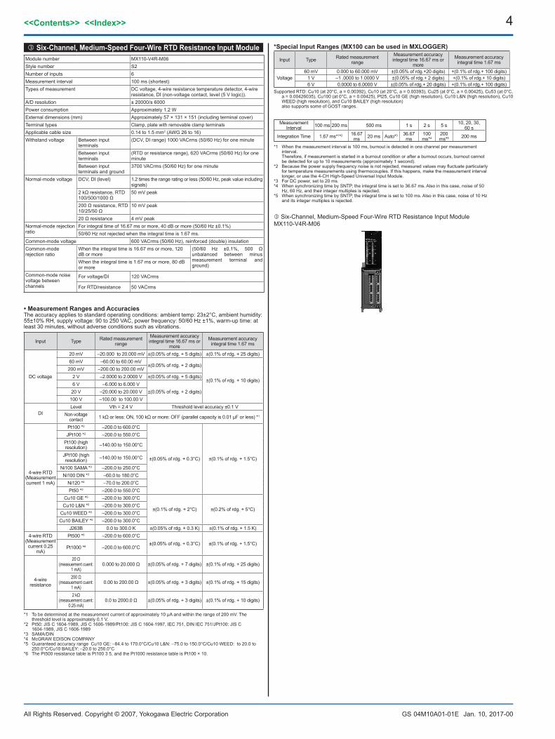
Six-Channel, Medium-Speed Four-Wire RTD Resistance Input ModuleMX110-V4R-M06
Six-Channel,Medium-SpeedFour-WireRTDResistanceInputModuleModule number MX110-V4R-M06Style number S2Number of inputs 6Measurement interval 100 ms (shortest)Types of measurement DC voltage, 4-wire resistance temperature detector, 4-wire
resistance, DI (non-voltage contact, level (5 V logic)).A/D resolution ± 20000/± 6000Power consumption Approximately 1.2 WExternal dimensions (mm) Approximately 57 × 131 × 151 (including terminal cover)Terminal types Clamp, plate with removable clamp terminalsApplicable cable size 0.14 to 1.5 mm2 (AWG 26 to 16)Withstand voltage Between input
terminals(DCV, DI range) 1000 VACrms (50/60 Hz) for one minute
Between input terminals
(RTD or resistance range), 620 VACrms (50/60 Hz) for one minute
Between input terminals and ground
3700 VACrms (50/60 Hz) for one minute
Normal-mode voltage DCV, DI (level) 1.2 times the range rating or less (50/60 Hz, peak value including signals)
2 kΩ resistance, RTD 100/500/1000 Ω
50 mV peak
200 Ω resistance, RTD 10/25/50 Ω
10 mV peak
20 Ω resistance 4 mV peakNormal-mode rejection ratio
For integral time of 16.67 ms or more, 40 dB or more (50/60 Hz ±0.1%)50/60 Hz not rejected when the integral time is 1.67 ms.
Common-mode voltage 600 VACrms (50/60 Hz), reinforced (double) insulationCommon-mode rejection ratio
When the integral time is 16.67 ms or more, 120 dB or more
(50/60 Hz ±0.1%, 500 Ω unbalanced between minus measurement terminal and ground)
When the integral time is 1.67 ms or more, 80 dB or more
Common-mode noise voltage between channels
For voltage/DI 120 VACrms
For RTD/resistance 50 VACrms
•MeasurementRangesandAccuraciesThe accuracy applies to standard operating conditions: ambient temp: 23±2°C, ambient humidity: 55±10% RH, supply voltage: 90 to 250 VAC, power frequency: 50/60 Hz ±1%, warm-up time: at least 30 minutes, without adverse conditions such as vibrations.
Input Type Rated measurement range
Measurement accuracy integral time 16.67 ms or
more Measurement accuracy
integral time 1.67 ms
DC voltage
20 mV –20.000 to 20.000 mV ±(0.05% of rdg. + 5 digits) ±(0.1% of rdg. + 25 digits)60 mV –60.00 to 60.00 mV
±(0.05% of rdg. + 2 digits)
±(0.1% of rdg. + 10 digits)
200 mV –200.00 to 200.00 mV2 V –2.0000 to 2.0000 V ±(0.05% of rdg. + 5 digits)6 V –6.000 to 6.000 V
±(0.05% of rdg. + 2 digits)20 V –20.000 to 20.000 V100 V –100.00 to 100.00 V
DILevel Vth = 2.4 V Threshold level accuracy ±0.1 V
Non-voltage contact 1 kΩ or less: ON, 100 kΩ or more: OFF (parallel capacity is 0.01 µF or less) *1
4-wire RTD(Measurement current 1 mA)
Pt100 *2 –200.0 to 600.0°C
±(0.05% of rdg. + 0.3°C) ±(0.1% of rdg. + 1.5°C)
JPt100 *2 –200.0 to 550.0°CPt100 (high resolution) –140.00 to 150.00°C
JPt100 (high resolution) –140.00 to 150.00°C
Ni100 SAMA *3 –200.0 to 250.0°CNi100 DIN *3 –60.0 to 180.0°C
Ni120 *4 –70.0 to 200.0°CPt50 *2 –200.0 to 550.0°C
Cu10 GE *5 –200.0 to 300.0°C
±(0.1% of rdg. + 2°C) ±(0.2% of rdg. + 5°C)Cu10 L&N *5 –200.0 to 300.0°C
Cu10 WEED *5 –200.0 to 300.0°CCu10 BAILEY *5 –200.0 to 300.0°C
J263B 0.0 to 300.0 K ±(0.05% of rdg. + 0.3 K) ±(0.1% of rdg. + 1.5 K)4-wire RTD
(Measurement current 0.25
mA)
Pt500 *6 –200.0 to 600.0°C±(0.05% of rdg. + 0.3°C) ±(0.1% of rdg. + 1.5°C)
Pt1000 *6 –200.0 to 600.0°C
4-wire resistance
20 Ω (measuement cuent:
1 mA)0.000 to 20.000 Ω ±(0.05% of rdg. + 7 digits) ±(0.1% of rdg. + 25 digits)
200 Ω(measuement cuent:
1 mA)0.00 to 200.00 Ω ±(0.05% of rdg. + 3 digits) ±(0.1% of rdg. + 15 digits)
2 kΩ(measuement cuent:
0.25 mA)0.0 to 2000.0 Ω ±(0.05% of rdg. + 3 digits) ±(0.1% of rdg. + 10 digits)
*1 To be determined at the measurement current of approximately 10 µA and within the range of 200 mV. The threshold level is approximately 0.1 V.
*2 Pt50: JIS C 1604-1989, JIS C 1606-1989/Pt100: JIS C 1604-1997, IEC 751, DIN IEC 751/JPt100: JIS C 1604-1989, JIS C 1606-1989
*3 SAMA/DIN*4 McGRAW EDISON COMPANY*5 Guaranteed accuracy range Cu10 GE: –84.4 to 170.0°C/Cu10 L&N: –75.0 to 150.0°C/Cu10 WEED: to 20.0 to
250.0°C/Cu10 BAILEY: –20.0 to 250.0°C*6 The Pt500 resistance table is Pt100 3 5, and the Pt1000 resistance table is Pt100 × 10.
*SpecialInputRanges(MX100canbeusedinMXLOGGER)
Input Type Rated measurement range
Measurement accuracy integral time 16.67 ms or
moreMeasurement accuracy
integral time 1.67 ms
Voltage60 mV 0.000 to 60.000 mV ±(0.05% of rdg.+20 digits) +(0.1% of rdg.+ 100 digits)
1 V –1 .0000 to 1.0000 V ±(0.05% of rdg.+ 2 digits) +(0.1% of rdg.+ 10 digits)6 V 0.0000 to 6.0000 V ±(0.05% of rdg.+ 20 digits) +(0.1% of rdg.+ 100 digits)
Supported RTD: Cu10 (at 20°C, a = 0.00392), Cu10 (at 20°C, a = 0.00393), Cu25 (at 0°C, a = 0.00425), Cu53 (at 0°C, a = 0.00426035), Cu100 (at 0°C, a = 0.00425), Pt25, Cu10 GE (high resolution), Cu10 L&N (high resolution), Cu10 WEED (high resolution), and Cu10 BAILEY (high resolution)
also supports some of GOST ranges.
Measurement Interval 100 ms 200 ms 500 ms 1 s 2 s 5 s 10, 20, 30,
60 s
Integration Time 1.67 ms*1*2 16.67 ms 20 ms Auto*3 36.67
ms100 ms*4
200 ms*5 200 ms
*1 When the measurement interval is 100 ms, burnout is detected in one channel per measurement interval. Therefore, if measurement is started in a burnout condition or after a burnout occurs, burnout cannot be detected for up to 10 measurements (approximately 1 second).
*2 Because the power supply frequency noise is not rejected, measured values may fluctuate particularly for temperature measurements using thermocouples. If this happens, make the measurement interval longer, or use the 4-CH High-Speed Universal Input Module.
*3 For DC power, set to 20 ms.*4 When synchronizing time by SNTP, the integral time is set to 36.67 ms. Also in this case, noise of 50
Hz, 60 Hz, and their integer multiples is rejected.*5 When synchronizing time by SNTP, the integral time is set to 100 ms. Also in this case, noise of 10 Hz
and its integer multiples is rejected.
5<<Contents>> <<Index>>
All Rights Reserved. Copyright © 2007, Yokogawa Electric Corporation GS 04M10A01-01E Jan. 10, 2017-00
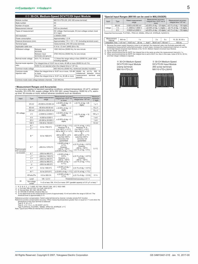
30-CH,Medium-SpeedDCV/TC/DIInputModuleModule number MX110-VTD-L30, (/H3: M3 screw terminal)Style number S3Number of inputs 30Measurement interval 500 ms (shortest) Types of measurement DC voltage, thermocouple, DI (non-voltage contact, level
(5 V logic)A/D resolution ± 20000/± 6000Power consumption Approximately 1.2 WExternal dimensions (mm) Approximately 174 × 131 × 151 (including terminal cover)Terminal types Clamp terminal, (/H3: M3 screw terminal)Applicable cable size 0.14 to 1.5 mm2 (AWG 26 to 16)Withstand voltage Between input
terminals1000 VACrms (50/60 Hz), for one minute
Between input terminals and ground
3700 VACrms (50/60 Hz), for one minute
Normal-mode voltage DCV, TC, DI (level) 1.2 times the range rating or less (50/60 Hz, peak value including signals)
Normal-mode rejection ratio
For integral time of 16.67 ms or more, 40 dB or more (50/60 Hz ±0.1%)50/60 Hz not rejected when the integral time is 1.67 ms.
Common-mode voltage 600 VACrms (50/60 Hz), reinforced (double) insulationCommon-mode rejection ratio
When the integral time is 16.67 ms or more, 120 dB or more
(50/60 Hz ±0.1%, 500 Ω unbalanced between minus measurement terminal and ground)
When the integral time is 16.67 ms, 80 dB or more
Common-mode noise voltage between channels 120 VACrms
•MeasurementRangesandAccuraciesThe accuracy applies to standard operating conditions: ambient temperature: 23 ±2°C, ambient humidity: 55 ±10% RH, supply voltage: 90 to 250 VAC, power frequency: 50/60 Hz ±1%, warm-up time: 30 minutes or more, without adverse conditions such as vibrations.
Input Type Rated measurement range
Measurement accuracy integral time 16.67 ms
or more Measurement accuracy
integral time 1.67 msMaximum resolution(1 digit)
DC voltage
20 mV –20.000 to 20.000 mV ± (0.05% of rdg. + 5 digits)
± (0.1% of rdg. + 25 digits) 1 μ V
60 mV –60.00 to 60.00 mV ± (0.05% of rdg. + 2 digits)
± (0.1% of rdg. + 10 digits)
10 μ V200 mV –200.00 to 200.00 mV 10 μ V
2 V –2.0000 to 2.0000 V ± (0.05% of rdg. + 5 digits) 100 μ V
6 V –6.000 to 6.000 V ± (0.05% of rdg. + 2
digits)
1 mV20 V –20.000 to 20.000 V 1 mV100 V –100.00 to 100.00 V 10 mV
Thermocouple RJC accuracy not included
R *1
0.0 to 1760.0°C± (0.05% of rdg. + 1°C)
However, R, S:0 to 100°C: ± 3.7°C
100 to 300°C: ± 1.5°CB:
400 to 600°C: ±2°CLess than 400°C:
accuracy not guaranteed
± (0.1% of rdg. + 4°C)However, R, S:
0 to 100°C: ± 10°C100 to 300°C: ± 5°C
B:400 to 600°C: ± 7°C
Less than 400°C: accuracy not guaranteed
0.1°C
S *1
B *1 0.0 to 1820.0°C
K *1 –200.0 to 1370.0°C
± (0.05% of rdg. + 0.7°C)
However, –200 to –100°C:
± (0.05% of rdg. + 1°C)
± (0.1% of rdg. + 3.5°C)However,
–200 to –100°C: ± (0.1% of rdg. + 6°C)
E *1 –200.0 to 800.0°C ± (0.05% of rdg. + 0.5°C)
However, J, L:–200 to –100°C: ±(0.05% of rdg. +
0.7°C)
± (0.1% of rdg. + 2.5°C)However,
–200 to –100°C: ± (0.1% of rdg. + 5°C)
J *1 –200.0 to 1100.0°CT *1 –200.0 to 400.0°CL *2 –200.0 to 900.0°CU –200.0 to 400.0°C
N *3 0.0 to 1300.0°C ± (0.05% of rdg. + 0.7°C) ± (0.1% of rdg. + 3.5°C)
W *4 0.0 to 2315.0°C ± (0.05% of rdg. + 1°C) ± (0.1% of rdg. + 7°C)
KPvsAu7Fe 0.0 to 300.0 K ± (0.05% of rdg. + 0.7 k) ± (0.1% of rdg. + 3.5 K) 0.1 k
DILevel Vth = 2.4 V Threshold level accuracy ± 0.1 V
Non-voltage contact 1 k Ω or less: ON, 10 k Ω or more: OFF (parallel capacity is 0.01 μF or less) *9
*1 R, S, B, K, E, J, T: ANSI, IEC 584, DIN IEC 584, JIS C 1602-1995*2 L: Fe-CuNi, DIN 43710/U: Cu-CuNi, DIN 43710*3 N: Nicrosil-Nisil, IEC 584, DIN IEC 584*4 W: W5%RE-W 26%Re (Hoskins Mfg Co) *5 To be determined at the measurement current of approximately 10 mA and within the range of 200 mV. The
threshold level is approximately 0.1V.
*SpecialInputRanges(MX100canbeusedinMXLOGGER)
Input Type Rated measurement range
Measurement accuracy integral time 16.67 ms or
moreMeasurement accuracy
integral time 1.67 ms
Voltage60 mV 0.000 to 60.000 mV ±(0.05% of rdg. + 20 digits) ±(0.1% of rdg. + 100 digits)
1 V –1 .0000 to 1.0000 V ±(0.05% of rdg. + 2 digits) ±(0.1% of rdg. + 10 digits)6 V 0.0000 to 6.0000 V ±(0.05% of rdg. + 20 digits) ±(0.1% of rdg. + 100 digits)
Supported thermocouple: PLATINEL, PR40-20, NiNiMo, WRe3-25, W/WRe26, N(AWG14)
30-CH Medium-Speed DCV/TC/DI Input Module (clamp terminal) MX110-VTD-L30
30-CH Medium-Speed DCV/TC/DI Input Module (M3 screw terminal)MX110-VTD-L30/H3
Measurement Interval 500 ms 1 s 2 s 5 s 10, 20, 30, 60 s
Integration Time 1.67 ms*1 16.67 ms 20 ms Auto*2 36.67 ms*3 100 ms*4 100 ms*1 Because the power supply frequency noise is not rejected, the measured vales may fluctuate especially with
temperature measurement using thermocouples. In such cases, increase the measurement interval, or use the 4-CH High-Speed Universal Input Module or the 10-CH, Medium Speed Universal Input Module.
*2 For DC power, set to 20 ms.*3 When synchronizing time by SNTP, the integral time is the same as when the measurement interval is 1 s.*4 When synchronizing time by SNTP, the integral time is set to 36.67 ms. Also in this case, noise of 50 Hz, 60 Hz,
and their integer multiples is rejected.
Reference junction compensation: Switch external/internal by channel, includes remote RJC functionReference junction compensation accuracy: When measuring temperature greater than or equal to 0 °C and when the
temperature of the input terminal is balanced Type R, S, W: ±1°C Type K, J, E, T, N, L, U, XK GOST: ±0.5°C Type N (AWG14), PLATINEL, NiNiMo, WRe3-25, W/WRe26: ±1°CNote: Type B and PR40-20 internal RJC is fixed at 0°C
6
All Rights Reserved. Copyright © 2007, Yokogawa Electric Corporation
<<Contents>> <<Index>>
GS 04M10A01-01E Jan. 10, 2017-00
4-CH Medium-Speed Strain Input ModuleMX112-NDI-M04
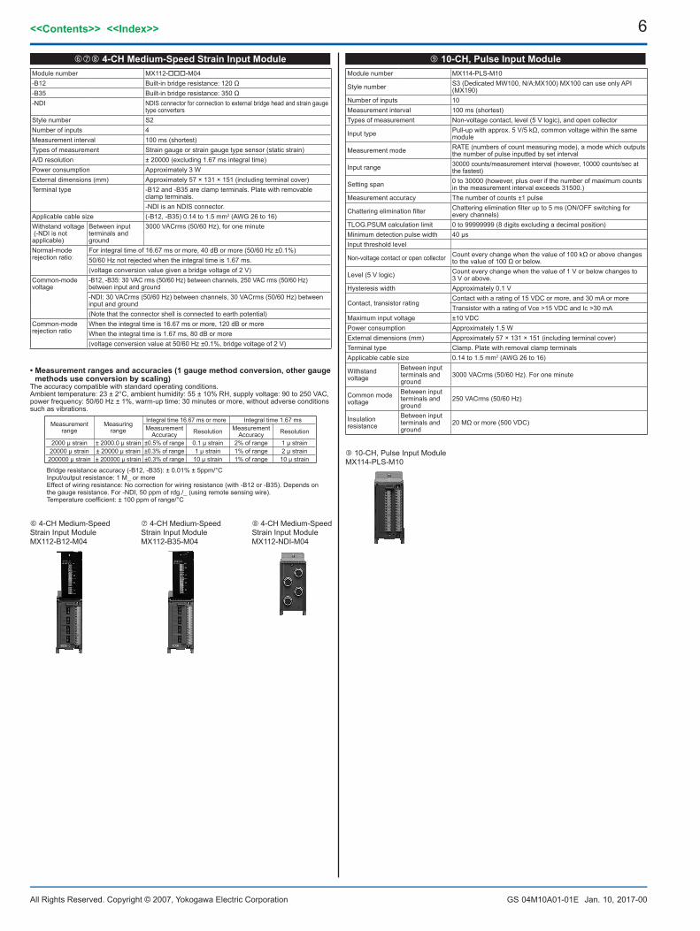
10-CH,PulseInputModuleModule number MX114-PLS-M10
Style number S3 (Dedicated MW100, N/A:MX100) MX100 can use only API (MX190)
Number of inputs 10Measurement interval 100 ms (shortest)Types of measurement Non-voltage contact, level (5 V logic), and open collector
Input type Pull-up with approx. 5 V/5 kΩ, common voltage within the same module
Measurement mode RATE (numbers of count measuring mode), a mode which outputs the number of pulse inputted by set interval
Input range 30000 counts/measurement interval (however, 10000 counts/sec at the fastest)
Setting span 0 to 30000 (however, plus over if the number of maximum counts in the measurement interval exceeds 31500.)
Measurement accuracy The number of counts ±1 pulse
Chattering elimination filter Chattering elimination filter up to 5 ms (ON/OFF switching for every channels)
TLOG.PSUM calculation limit 0 to 99999999 (8 digits excluding a decimal position)Minimum detection pulse width 40 µs Input threshold level
Non-voltage contact or open collector Count every change when the value of 100 kΩ or above changes to the value of 100 Ω or below.
Level (5 V logic) Count every change when the value of 1 V or below changes to 3 V or above.
Hysteresis width Approximately 0.1 V
Contact, transistor ratingContact with a rating of 15 VDC or more, and 30 mA or moreTransistor with a rating of Vce >15 VDC and Ic >30 mA
Maximum input voltage ±10 VDCPower consumption Approximately 1.5 WExternal dimensions (mm) Approximately 57 × 131 × 151 (including terminal cover) Terminal type Clamp. Plate with removal clamp terminals Applicable cable size 0.14 to 1.5 mm2 (AWG 26 to 16)
Withstand voltage
Between input terminals and ground
3000 VACrms (50/60 Hz). For one minute
Common mode voltage
Between input terminals and ground
250 VACrms (50/60 Hz)
Insulation resistance
Between input terminals and ground
20 MΩ or more (500 VDC)
4-CH Medium-Speed Strain Input ModuleMX112-B12-M04
4-CH Medium-Speed Strain Input ModuleMX112-B35-M04
10-CH, Pulse Input Module MX114-PLS-M10
4-CHMedium-SpeedStrainInputModuleModule number MX112--M04-B12 Built-in bridge resistance: 120 Ω-B35 Built-in bridge resistance: 350 Ω-NDI NDIS connector for connection to external bridge head and strain gauge
type convertersStyle number S2Number of inputs 4Measurement interval 100 ms (shortest)Types of measurement Strain gauge or strain gauge type sensor (static strain)A/D resolution ± 20000 (excluding 1.67 ms integral time)Power consumption Approximately 3 WExternal dimensions (mm) Approximately 57 × 131 × 151 (including terminal cover)Terminal type -B12 and -B35 are clamp terminals. Plate with removable
clamp terminals.-NDI is an NDIS connector.
Applicable cable size (-B12, -B35) 0.14 to 1.5 mm2 (AWG 26 to 16)Withstand voltage (-NDI is not applicable)
Between input terminals and ground
3000 VACrms (50/60 Hz), for one minute
Normal-mode rejection ratio:
For integral time of 16.67 ms or more, 40 dB or more (50/60 Hz ±0.1%)50/60 Hz not rejected when the integral time is 1.67 ms. (voltage conversion value given a bridge voltage of 2 V)
Common-mode voltage
-B12, -B35: 30 VAC rms (50/60 Hz) between channels, 250 VAC rms (50/60 Hz) between input and ground-NDI: 30 VACrms (50/60 Hz) between channels, 30 VACrms (50/60 Hz) between input and ground(Note that the connector shell is connected to earth potential)
Common-mode rejection ratio
When the integral time is 16.67 ms or more, 120 dB or moreWhen the integral time is 1.67 ms, 80 dB or more(voltage conversion value at 50/60 Hz ±0.1%, bridge voltage of 2 V)
•Measurementrangesandaccuracies(1gaugemethodconversion,othergaugemethodsuseconversionbyscaling)
The accuracy compatible with standard operating conditions.Ambient temperature: 23 ± 2°C, ambient humidity: 55 ± 10% RH, supply voltage: 90 to 250 VAC, power frequency: 50/60 Hz ± 1%, warm-up time: 30 minutes or more, without adverse conditions such as vibrations.
Measurement range
Measuring range
Integral time 16.67 ms or more Integral time 1.67 msMeasurement
Accuracy Resolution Measurement Accuracy Resolution
2000 µ strain ± 2000.0 µ strain ±0.5% of range 0.1 µ strain 2% of range 1 μ strain20000 µ strain ± 20000 µ strain ±0.3% of range 1 µ strain 1% of range 2 μ strain
200000 µ strain ± 200000 µ strain ±0.3% of range 10 µ strain 1% of range 10 μ strain
Bridge resistance accuracy (-B12, -B35): ± 0.01% ± 5ppm/°CInput/output resistance: 1 M_ or moreEffect of wiring resistance: No correction for wiring resistance (with -B12 or -B35). Depends on the gauge resistance. For -NDI, 50 ppm of rdg./_ (using remote sensing wire). Temperature coefficient: ± 100 ppm of range/°C
7<<Contents>> <<Index>>
All Rights Reserved. Copyright © 2007, Yokogawa Electric Corporation GS 04M10A01-01E Jan. 10, 2017-00
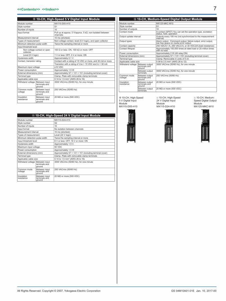
10-CH,High-Speed5VDigitalInputModuleModule number MX115-D05-H10Style number S1Number of inputs 10Input format Pull up at approx. 5 V/approx. 5 kΩ, non-isolated between
channelsMeasurement interval 10 ms (shortest)Types of measurement Non-voltage contact, level (5-V logic), and open collectorMinimum detection pulse width Twice the sampling interval or moreInput threshold level
Non-voltage contact or open collector
100 Ω or less: ON, 100 kΩ or more: OFF
Level (5 V logic) 1 V or less: OFF, 3 V or more: ONHysteresis width Approximately 0.1 VContact, transistor rating Contact with a rating of 15 VDC or more, and 30 mA or more
Transistor with a rating of Vce > 15 VDC and Ic > 30 mAMaximum input voltage ±10 VDCPower consumption Approximately 1.5 WExternal dimensions (mm) Approximately 57 × 131 × 151 (including terminal cover)Terminal type Clamp. Plate with removable clamp terminals Applicable cable size 0.14 to 1.5 mm2 (AWG 26 to 16)Withstand voltage Between input
terminals and ground
3000 VACrms (50/60 Hz), for one minute
Common mode voltage
Between input terminals and ground
250 VACrms (50/60 Hz)
Insulation resistance
Between input terminals and ground
20 MΩ or more (500 VDC)
10-CH,Medium-SpeedDigitalOutputModuleModule number MX125-MKC-M10Style number S1Number of outputs 10Contact mode A contact (SPST) You can set the operation type, excitation
status, hold, operationOutput update interval Outputs every 100 ms (not synchronized to the measurement
interval)Output types Alarm output. Command output, failure output, error output,
low free space on media error output.Contact capacity 250 VDC/0.1 A, 250 VAC/2 A, or 30 VDC/2A (load resistance)Contact lifespan Approximately 100,000 times at rated load or 20 million times
with no load. Power consumption Approximately 2 W (All relay:ON)External dimensions (mm) Approximately 57 × 131 ×151 (including terminal cover)Terminal type Clamp. Removable in units of 5 ch. Applicable cable size 0.08 to 2.5 mm2 (AWG 28 to 12)Withstand voltage Between output
terminals and ground
3000 VACrms (50/60 Hz), for one minute
Between output terminals
3000 VACrms (50/60 Hz), for one minute
Common mode voltage
Between output terminals and ground
250 VACrms (50/60 Hz)
Insulation resistance
Between output terminals and ground
20 MΩ or more (500 VDC)
Between output terminals
20 MΩ or more (500 VDC)
10-CH, High-Speed 5 V Digital Input ModuleMX115-D05-H10
10-CH, Medium-Speed Digital Output ModuleMX125-MKC-M10
10-CH, High-Speed 24 V Digital Input ModuleMX115-D24-H10
10-CH,High-Speed24VDigitalInputModuleModule number MX115-D24-H10Style number S2Number of inputs 10Input format No isolation between channelsMeasurement Interval 10 ms (shortest)Types of measurement Level (24 V logic)Minimum detection pulse width Twice the sampling interval or moreInput threshold level 6 V or less: OFF, 16 V or more: ONHysteresis width Approximately 1.5 V.Maximum input voltage 50 VDC Power consumption Approximately 1.5 WExternal dimensions (mm) Approximately 57 × 131 × 151 (including terminal cover)Terminal type Clamp. Plate with removable clamp terminalsApplicable cable size 0.14 to 1.5 mm2 (AWG 26 to 16)Withstand voltage Between input
terminals and ground
3000 VACrms (50/60 Hz), for one minute
Common mode voltage
Between input terminals and ground
250 VACrms (50/60 Hz)
Insulation resistance
Between input terminals and ground
20 MΩ or more (500 VDC)
8
All Rights Reserved. Copyright © 2007, Yokogawa Electric Corporation
<<Contents>> <<Index>>
GS 04M10A01-01E Jan. 10, 2017-00
8-CH, Medium-Speed Analog Output ModuleMX120-VAO-M08
8-CH, Medium-Speed PWM Output ModuleMX120-PWM-M08
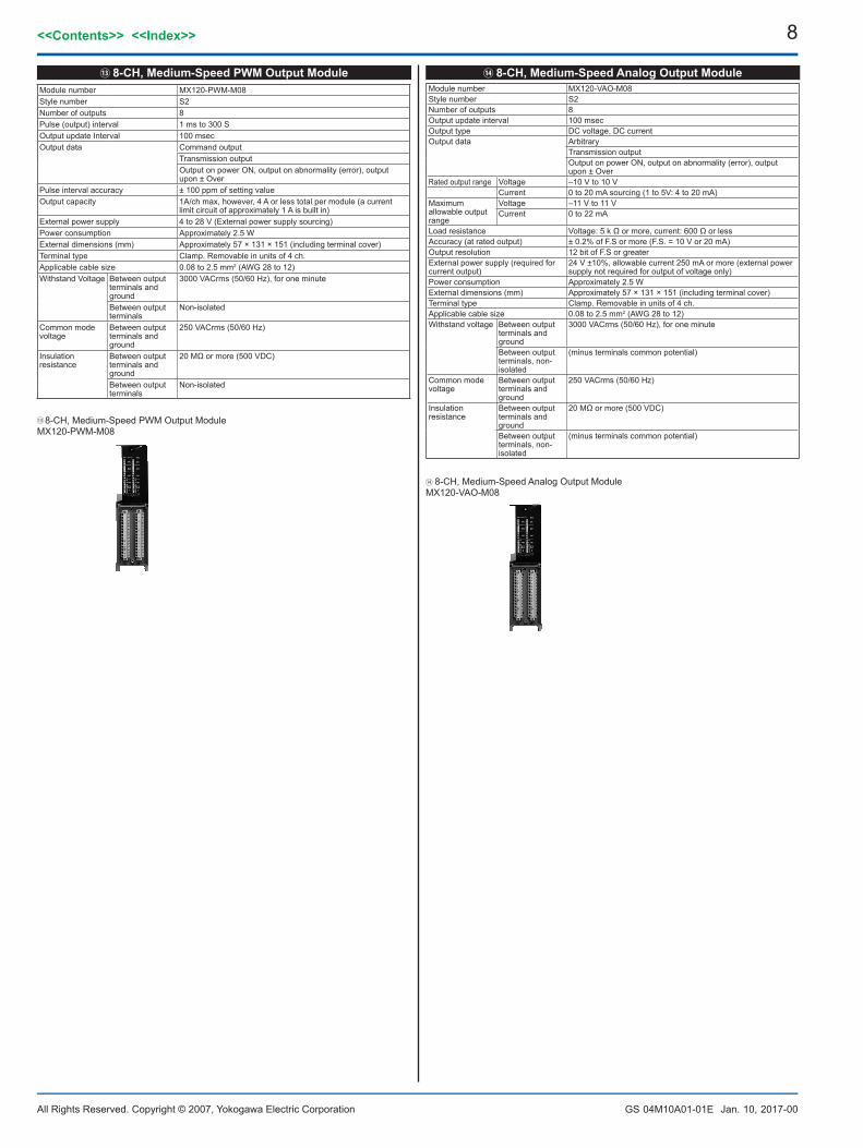
8-CH,Medium-SpeedPWMOutputModuleModule number MX120-PWM-M08Style number S2Number of outputs 8Pulse (output) interval 1 ms to 300 SOutput update Interval 100 msecOutput data Command output
Transmission outputOutput on power ON, output on abnormality (error), output upon ± Over
Pulse interval accuracy ± 100 ppm of setting valueOutput capacity 1A/ch max, however, 4 A or less total per module (a current
limit circuit of approximately 1 A is built in)External power supply 4 to 28 V (External power supply sourcing)Power consumption Approximately 2.5 WExternal dimensions (mm) Approximately 57 × 131 × 151 (including terminal cover)Terminal type Clamp. Removable in units of 4 ch. Applicable cable size 0.08 to 2.5 mm2 (AWG 28 to 12)Withstand Voltage Between output
terminals and ground
3000 VACrms (50/60 Hz), for one minute
Between output terminals
Non-isolated
Common mode voltage
Between output terminals and ground
250 VACrms (50/60 Hz)
Insulation resistance
Between output terminals and ground
20 MΩ or more (500 VDC)
Between output terminals
Non-isolated
8-CH,Medium-SpeedAnalogOutputModuleModule number MX120-VAO-M08Style number S2Number of outputs 8Output update interval 100 msecOutput type DC voltage, DC currentOutput data Arbitrary
Transmission outputOutput on power ON, output on abnormality (error), output upon ± Over
Rated output range Voltage –10 V to 10 VCurrent 0 to 20 mA sourcing (1 to 5V: 4 to 20 mA)
Maximum allowable output range
Voltage –11 V to 11 VCurrent 0 to 22 mA
Load resistance Voltage: 5 k Ω or more, current: 600 Ω or lessAccuracy (at rated output) ± 0.2% of F.S or more (F.S. = 10 V or 20 mA)Output resolution 12 bit of F.S or greaterExternal power supply (required for current output)
24 V ±10%, allowable current 250 mA or more (external power supply not required for output of voltage only)
Power consumption Approximately 2.5 WExternal dimensions (mm) Approximately 57 × 131 × 151 (including terminal cover)Terminal type Clamp. Removable in units of 4 ch. Applicable cable size 0.08 to 2.5 mm2 (AWG 28 to 12)Withstand voltage Between output
terminals and ground
3000 VACrms (50/60 Hz), for one minute
Between output terminals, non-isolated
(minus terminals common potential)
Common mode voltage
Between output terminals and ground
250 VACrms (50/60 Hz)
Insulation resistance
Between output terminals and ground
20 MΩ or more (500 VDC)
Between output terminals, non-isolated
(minus terminals common potential)
9<<Contents>> <<Index>>
All Rights Reserved. Copyright © 2007, Yokogawa Electric Corporation GS 04M10A01-01E Jan. 10, 2017-00
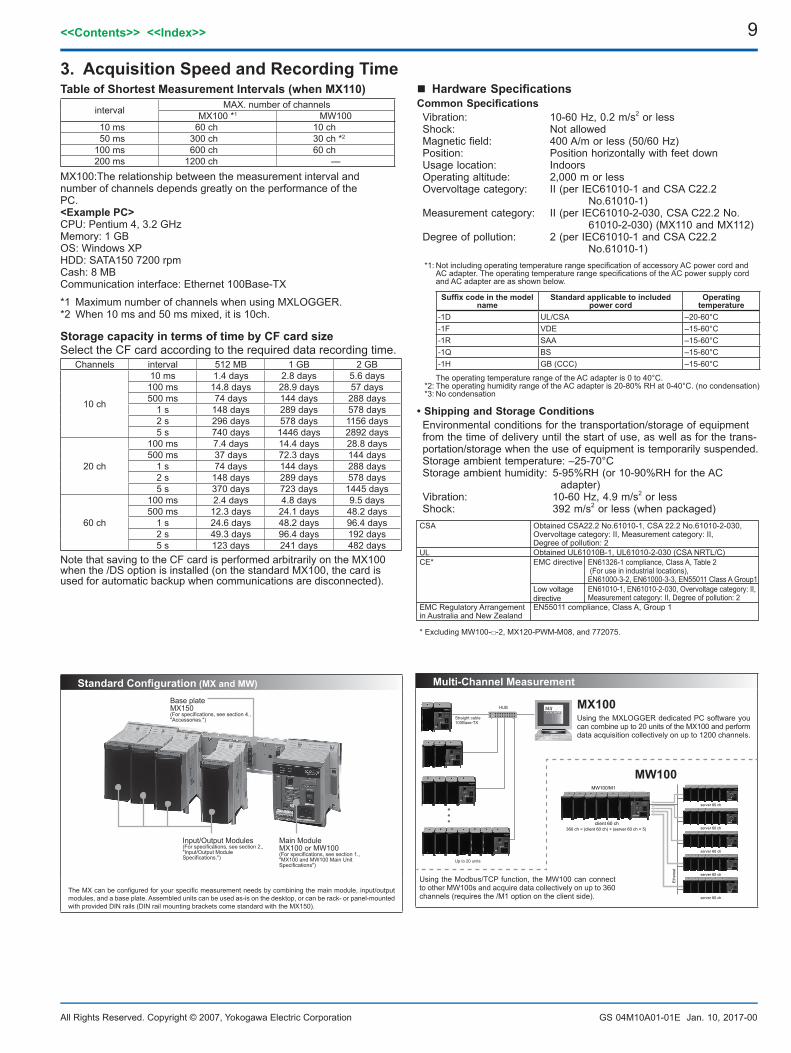
TableofShortestMeasurementIntervals(whenMX110)
interval MAX. number of channelsMX100 *1 MW100
10 ms 60 ch 10 ch 50 ms 300 ch 30 ch *2
100 ms 600 ch 60 ch 200 ms 1200 ch —
MX100:The relationship between the measurement interval and number of channels depends greatly on the performance of the PC.<ExamplePC>CPU: Pentium 4, 3.2 GHzMemory: 1 GBOS: Windows XPHDD: SATA150 7200 rpmCash: 8 MBCommunication interface: Ethernet 100Base-TX
*1 Maximum number of channels when using MXLOGGER. *2 When 10 ms and 50 ms mixed, it is 10ch.
3. AcquisitionSpeedandRecordingTime
StoragecapacityintermsoftimebyCFcardsizeSelect the CF card according to the required data recording time.
Channels interval 512 MB 1 GB 2 GB
10 ch
10 ms 1.4 days 2.8 days 5.6 days100 ms 14.8 days 28.9 days 57 days500 ms 74 days 144 days 288 days
1 s 148 days 289 days 578 days2 s 296 days 578 days 1156 days5 s 740 days 1446 days 2892 days
20 ch
100 ms 7.4 days 14.4 days 28.8 days500 ms 37 days 72.3 days 144 days
1 s 74 days 144 days 288 days2 s 148 days 289 days 578 days5 s 370 days 723 days 1445 days
60 ch
100 ms 2.4 days 4.8 days 9.5 days500 ms 12.3 days 24.1 days 48.2 days
1 s 24.6 days 48.2 days 96.4 days2 s 49.3 days 96.4 days 192 days5 s 123 days 241 days 482 days
Note that saving to the CF card is performed arbitrarily on the MX100 when the /DS option is installed (on the standard MX100, the card is used for automatic backup when communications are disconnected).
n HardwareSpecificationsCommonSpecificationsVibration: 10-60 Hz, 0.2 m/s2 or lessShock: Not allowedMagnetic field: 400 A/m or less (50/60 Hz)Position: Position horizontally with feet downUsage location: IndoorsOperating altitude: 2,000 m or lessOvervoltage category: II (per IEC61010-1 and CSA C22.2
No.61010-1) Measurement category: II (per IEC61010-2-030, CSA C22.2 No.
61010-2-030) (MX110 and MX112)Degree of pollution: 2 (per IEC61010-1 and CSA C22.2
No.61010-1) *1: Not including operating temperature range specification of accessory AC power cord and
AC adapter. The operating temperature range specifications of the AC power supply cord and AC adapter are as shown below.
Suffixcodeinthemodelname
Standardapplicabletoincludedpowercord
Operating temperature
-1D UL/CSA –20-60°C -1F VDE –15-60°C -1R SAA –15-60°C -1Q BS –15-60°C -1H GB (CCC) –15-60°C
The operating temperature range of the AC adapter is 0 to 40°C.*2: The operating humidity range of the AC adapter is 20-80% RH at 0-40°C. (no condensation)*3: No condensation
•ShippingandStorageConditionsEnvironmental conditions for the transportation/storage of equipment from the time of delivery until the start of use, as well as for the trans-portation/storage when the use of equipment is temporarily suspended.Storage ambient temperature: –25-70°C Storage ambient humidity: 5-95%RH (or 10-90%RH for the AC
adapter)Vibration: 10-60 Hz, 4.9 m/s2 or lessShock: 392 m/s2 or less (when packaged)
CSA
UL
EMC Regulatory Arrangement in Australia and New Zealand
CE*
Obtained CSA22.2 No.61010-1, CSA 22.2 No.61010-2-030, Overvoltage category: II, Measurement category: II, Degree of pollution: 2Obtained UL61010B-1, UL61010-2-030 (CSA NRTL/C)
EN55011 compliance, Class A, Group 1
EMC directive
Low voltage directive
EN61326-1 compliance, Class A, Table 2 (For use in industrial locations), EN61000-3-2, EN61000-3-3, EN55011 Class A Group1EN61010-1, EN61010-2-030, Overvoltage category: II, Measurement category: II, Degree of pollution: 2
* Excluding MW100--2, MX120-PWM-M08, and 772075.
StandardConfiguration(MXandMW)
Base plateMX150(For specifications, see section 4., "Accessories.")
Main ModuleMX100 or MW100(For specifications, see section 1., "MX100 and MW100 Main Unit Specifications")
Input/Output Modules(For specifications, see section 2., "Input/Output Module Specifications.")
The MX can be configured for your specific measurement needs by combining the main module, input/output modules, and a base plate. Assembled units can be used as-is on the desktop, or can be rack- or panel-mounted with provided DIN rails (DIN rail mounting brackets come standard with the MX150).
Multi-ChannelMeasurement
Using the Modbus/TCP function, the MW100 can connect to other MW100s and acquire data collectively on up to 360 channels (requires the /M1 option on the client side).
MX100Using the MXLOGGER dedicated PC software you can combine up to 20 units of the MX100 and perform data acquisition collectively on up to 1200 channels.
server 60 ch
client 60 ch360 ch = (client 60 ch) + (server 60 ch × 5)
MW100/M1
server 60 ch
server 60 ch
server 60 ch
server 60 ch
Eth
erne
t
MW100
Straight cable100Base-TX
HUB
Up to 20 units
10
All Rights Reserved. Copyright © 2007, Yokogawa Electric Corporation
<<Contents>> <<Index>>
GS 04M10A01-01E Jan. 10, 2017-00
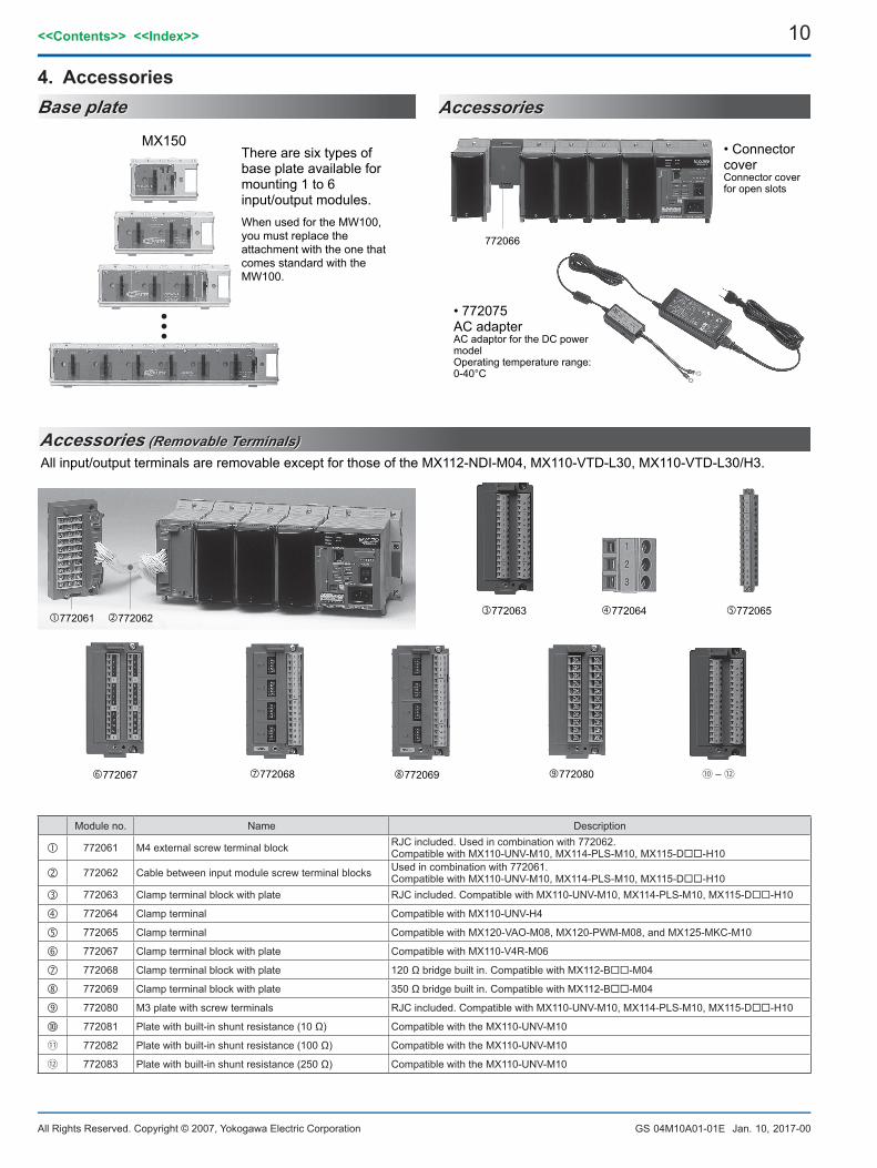
Module no. Name Description
772061 M4 external screw terminal block RJC included. Used in combination with 772062.Compatible with MX110-UNV-M10, MX114-PLS-M10, MX115-D-H10
772062 Cable between input module screw terminal blocks Used in combination with 772061. Compatible with MX110-UNV-M10, MX114-PLS-M10, MX115-D-H10
772063 Clamp terminal block with plate RJC included. Compatible with MX110-UNV-M10, MX114-PLS-M10, MX115-D-H10
772064 Clamp terminal Compatible with MX110-UNV-H4
772065 Clamp terminal Compatible with MX120-VAO-M08, MX120-PWM-M08, and MX125-MKC-M10
772067 Clamp terminal block with plate Compatible with MX110-V4R-M06
772068 Clamp terminal block with plate 120 Ω bridge built in. Compatible with MX112-B-M04
772069 Clamp terminal block with plate 350 Ω bridge built in. Compatible with MX112-B-M04
772080 M3 plate with screw terminals RJC included. Compatible with MX110-UNV-M10, MX114-PLS-M10, MX115-D-H10
772081 Plate with built-in shunt resistance (10 Ω) Compatible with the MX110-UNV-M10
772082 Plate with built-in shunt resistance (100 Ω) Compatible with the MX110-UNV-M10
772083 Plate with built-in shunt resistance (250 Ω) Compatible with the MX110-UNV-M10
Accessories (Removable Terminals)Accessories (Removable Terminals)
Base plateBase plate AccessoriesAccessories
MX150
772080
772065
772068772067 772069
772064772063772062772061
772066
All input/output terminals are removable except for those of the MX112-NDI-M04, MX110-VTD-L30, MX110-VTD-L30/H3.
There are six types of base plate available for mounting 1 to 6 input/output modules. When used for the MW100, you must replace the attachment with the one that comes standard with the MW100.
• Connector coverConnector cover for open slots
• 772075AC adapterAC adaptor for the DC power model Operating temperature range: 0-40°C
4. Accessories
11<<Contents>> <<Index>>
All Rights Reserved. Copyright © 2007, Yokogawa Electric Corporation GS 04M10A01-01E Jan. 10, 2017-00
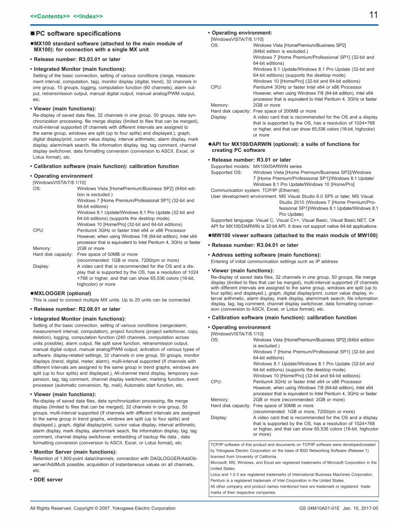
nPCsoftwarespecificationsMX100standardsoftware(attachedtothemainmoduleofMX100):forconnectionwithasingleMXunit
•Releasenumber:R3.03.01orlater
•IntegratedMonitor(mainfunctions):Setting of the basic connection, setting of various conditions (range, measure-ment interval, computation, tag), monitor display (digital, trend), 32 channels in one group, 10 groups, logging, computation function (60 channels), alarm out-put, retransmission output, manual digital output, manual analog/PWM output, etc.
•Viewer(mainfunctions):Re-display of saved data files, 32 channels in one group, 50 groups, data syn-chronization processing, file merge display (limited to files that can be merged), multi-interval supported (If channels with different intervals are assigned to the same group, windows are split (up to four splits) and displayed.), graph, digital display/print, cursor value display, interval arithmetic, alarm display, mark display, alarm/mark search, file information display, tag, tag comment, channel display switchover, data formatting conversion (conversion to ASCII, Excel, or Lotus format), etc.
•Calibrationsoftware(mainfunction):calibrationfunction
•Operatingenvironment[WindowsVISTA/7/8.1/10]OS: Windows Vista [HomePremium/Business SP2] (64bit edi-
tion is excluded.) Windows 7 [Home Premium/Professional SP1] (32-bit and
64-bit editions) Windows 8.1 Update/Windows 8.1 Pro Update (32-bit and
64-bit editions) (supports the desktop mode) Windows 10 [Home/Pro] (32-bit and 64-bit editions)
CPU: Pentium4 3GHz or faster Intel x64 or x86 Processor However, when using Windows 7/8 (64-bit edition), Intel x64
processor that is equivalent to Intel Pentium 4, 3GHz or fasterMemory: 2GB or moreHard disk capacity: Free space of 50MB or more (recommended: 1GB or more, 7200rpm or more)Display: A video card that is recommended for the OS and a dis-
play that is supported by the OS, has a resolution of 1024×768 or higher, and that can show 65,536 colors (16-bit, highcolor) or more
MXLOGGER(optional)This is used to connect multiple MX units. Up to 20 units can be connected.
•Releasenumber:R2.08.01orlater
•IntegratedMonitor(mainfunctions):Setting of the basic connection, setting of various conditions (range/alarm, measurement interval, computation), project functions (project switchover, copy, deletion), logging, computation function (240 channels, computation across units possible), alarm output, file split save function, retransmission output, manual digital output, manual analog/PWM output, activation of various types of software, display-related settings, 32 channels in one group, 50 groups, monitor displays (trend, digital, meter, alarm), multi-interval supported (If channels with different intervals are assigned to the same group in trend graphs, windows are split (up to four splits) and displayed.), All-channel trend display, temporary sus-pension, tag, tag comment, channel display switchover, marking function, event processor (automatic conversion, ftp, mail), Automatic start function, etc.
•Viewer(mainfunctions):Re-display of saved data files, data synchronization processing, file merge display (limited to files that can be merged), 32 channels in one group, 50 groups, multi-interval supported (If channels with different intervals are assigned to the same group in trend graphs, windows are split (up to four splits) and displayed.), graph, digital display/print, cursor value display, interval arithmetic, alarm display, mark display, alarm/mark seach, file information display, tag, tag comment, channel display switchover, embedding of backup file data , data formatting conversion (conversion to ASCII, Excel, or Lotus format), etc.
•MonitorServer(mainfunctions):Retention of 1,800-point data/channels, connection with DAQLOGGER/AddOb-server/AddMulti possible, acquisition of instantaneous values on all channels, etc.
•DDEserver
•Operatingenvironment:[WindowsVISTA/7/8.1/10]OS: Windows Vista [HomePremium/Business SP2] (64bit edition is excluded.) Windows 7 [Home Premium/Professional SP1] (32-bit and
64-bit editions) Windows 8.1 Update/Windows 8.1 Pro Update (32-bit and
64-bit editions) (supports the desktop mode) Windows 10 [Home/Pro] (32-bit and 64-bit editions)CPU: Pentium4 3GHz or faster Intel x64 or x86 Processor However, when using Windows 7/8 (64-bit edition), Intel x64
processor that is equivalent to Intel Pentium 4, 3GHz or fasterMemory: 2GB or moreHard disk capacity: Free space of 200MB or moreDisplay: A video card that is recommended for the OS and a display
that is supported by the OS, has a resolution of 1024×768 or higher, and that can show 65,536 colors (16-bit, highcolor) or more
APIforMX100/DARWIN(optional):asuiteoffunctionsforcreatingPCsoftware
•Releasenumber:R3.01orlaterSupported models: MX100/DARWIN seriesSupported OS: Windows Vista [Home Premium/Business SP2]/Windows
7 [Home Premium/Professional SP1]/Windows 8.1 Update/Windows 8.1 Pro Update/Windows 10 [Home/Pro]
Communication system: TCP/IP (Ethernet)User development environment: MS Visual Studio 6.0 SP5 or later, MS Visual
Studio 2010 (Windows 7 [Home Premium/Pro-fessional SP1]/Windows 8.1 Update/Windows 8.1 Pro Update)
Supported language: Visual C, Visual C++, Visual Basic, Visual Basic.NET, C#API for MX100/DARWIN is 32-bit API. It does not support native 64-bit applications.
MW100viewersoftware(attachedtothemainmoduleofMW100)
•Releasenumber:R3.04.01orlater
•Addresssettingsoftware(mainfunctions):Entering of initial communication settings such as IP address
•Viewer(mainfunctions):Re-display of saved data files, 32 channels in one group, 50 groups, file merge display (limited to files that can be merged), multi-interval supported (If channels with different intervals are assigned to the same group, windows are split (up to four splits) and displayed.), graph, digital display/print, cursor value display, in-terval arithmetic, alarm display, mark display, alarm/mark search, file information display, tag, tag comment, channel display switchover, data formatting conver-sion (conversion to ASCII, Excel, or Lotus format), etc.
•Calibrationsoftware(mainfunction):calibrationfunction
•Operatingenvironment[WindowsVISTA/7/8.1/10]OS: Windows Vista [HomePremium/Business SP2] (64bit edition
is excluded.) Windows 7 [Home Premium/Professional SP1] (32-bit and
64-bit editions) Windows 8.1 Update/Windows 8.1 Pro Update (32-bit and
64-bit editions) (supports the desktop mode) Windows 10 [Home/Pro] (32-bit and 64-bit editions)CPU: Pentium4 3GHz or faster Intel x64 or x86 Processor However, when using Windows 7/8 (64-bit edition), Intel x64
processor that is equivalent to Intel Pentium 4, 3GHz or fasterMemory: 2GB or more (recommended: 2GB or more)Hard disk capacity: Free space of 50MB or more (recommended: 1GB or more, 7200rpm or more)Display: A video card that is recommended for the OS and a display
that is supported by the OS, has a resolution of 1024×768 or higher, and that can show 65,536 colors (16-bit, highcolor or more)
TCP/IP software of this product and documents on TCP/IP software were developed/created by Yokogawa Electric Corporation on the basis of BSD Networking Software (Release 1) licensed from University of California.Microsoft, MS, Windows, and Excel are registered trademarks of Microsoft Corporation in the United States.Lotus and 1-2-3 are registered trademarks of International Business Machines Corporation.Pentium is a registered trademark of Intel Corporation in the United States.All other company and product names mentioned here are trademark or registered trade-marks of their respective companies.
12
All Rights Reserved. Copyright © 2007, Yokogawa Electric Corporation
<<Contents>> <<Index>>
GS 04M10A01-01E Jan. 10, 2017-00
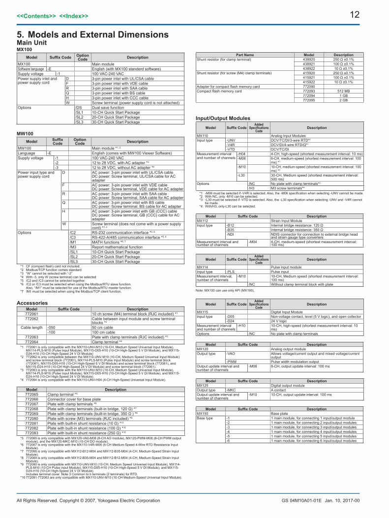
5.ModelsandExternalDimensionsMain UnitMX100
Model SuffixCode OptionCode Description
MX100 Main moduleSoftware language -E English (with MX100 standerd software)Supply voltage -1 100 VAC-240 VACPower supply inlet and power supply cord
D 3-pin power intel with UL/CSA cableF 3-pin power intel with VDE cableR 3-pin power intel with SAA cableQ 3-pin power intel with BS cableH 3-pin power inlet with CCC cableW Screw terminal (power supply cord is not attached)
Options /DS Dual save function/SL1 10-CH Quick Start Package/SL2 20-CH Quick Start Package/SL3 30-CH Quick Start Package
MW100Model Suffix
CodeOptionCode Description
MW100 Main module *1, 2
Language -E English (comes with MW100 Viewer Software)Supply voltage -1 100 VAC-240 VAC
-2 12 to 28 VDC, with AC adapter *3
-3 12 to 28 VDC, without AC adapter *4
Power input type and power supply cord
D AC power: 3-pin power inlet with UL/CSA cableDC power: Screw terminal, UL/CSA cable for AC adapter
F AC power: 3-pin power inlet with VDE cableDC power: Screw terminal, VDE cable for AC adapter
R AC power: 3-pin power inlet with SAA cableDC power: Screw terminal, SAA cable for AC adapter
Q AC power: 3-pin power inlet with BS cableDC power: Screw terminal, BS cable for AC adapter
H AC power: 3-pin power inlet with GB (CCC) cableDC power: Screw terminal, GB (CCC) cable for AC adapter
W Screw terminal (does not come with a power supply cord) *3, 4
Options /C2 RS-232 communication interface *5, 6
/C3 RS-422-A/485 communication interface *5, 6
/M1 MATH functions *6, 7
/M3 Report mathematical function/SL1 10-CH Quick Start Package/SL2 20-CH Quick Start Package/SL3 30-CH Quick Start Package
*1 CF (compact flash) card not included. *2 Modbus/TCP function comes standard*3 “W” cannot be selected with “-2”*4 With -3, only W (screw terminal) can be selected*5 /C2 and /C3 cannot be selected together. *6 /C2 or /C3 must be selected when using the Modbus/RTU slave function. Also, “/M1” must be selected for use of the Modbus/RTU master function. *7 /M1 must be selected when using the Modbus/TCP client function.
AccessoriesModel SuffixCode Description772061 10 ch screw (M4) terminal block (RJC included) *1
772062 Cable between input module and screw terminal blocks *2
Cable length -050 50 cm cable-100 100 cm cable
772063 Plate with clamp terminals (RJC included) *3
772064 Clamp terminal *4
*1 772061 is only compatible with the MX110-UNV-M10 (10-CH, Medium Speed Universal Input Module), MX114-PLS-M10 (Pulse Input Module), MX115-D05-H10 (10-CH High-Speed 5 V DI Module), and MX115-D24-H10 (10-CH High-Speed 24 V DI Module)
*2 772062 is only compatible between the MX110-UNV-M10 (10-CH, Medium Speed Universal Input Module) and screw terminal block (772061), MX114-PLS-M10 (Pulse Input Module) and screw terminal block (772061), MX115-D05-H10 (10-CH High-Speed 5 V DI Module) and screw terminal block (772061), and MX115-D24-H10 (10-CH High-Speed 24 V DI Module) and screw terminal block (772061).
*3 772063 is only compatible with the MX110-UNV-M10 (10-CH, Medium Speed Universal Input Module), MX114-PLS-M10 (Pulse Input Module), MX115-D05-H10 (10-CH High-Speed 5 V DI Module), and MX115-D24-H10 (10-CH High-Speed 24 V DI Module).
*4 772064 is only compatible with the MX110-UNV-H04 (4-CH High-Speed Universal Input Module).
Model Description772065 Clamp terminal *5
772066 Connector cover for base plate772067 Plate with clamp terminals *6
772068 Plate with clamp terminals (built-in bridge, 120 Ω) *7
772069 Plate with clamp terminals (built-in bridge, 350 Ω ) *8
772080 Plate with screw (M3) terminals (RJC included) *9
772081 Plate with built-in shunt resistance (10 Ω) *10
772082 Plate with built-in shunt resistance (100 Ω) *10
772083 Plate with built-in shunt resistance (250 Ω) *10
*5 772065 is only compatible with MX120-VA0-M08 (8-CH AO module), MX120-PWM-M08 (8-CH PWM output module), and the MX120-MKC-M10 (10-CH DO module).
*6 772067 is only compatible with the MX110-V4R-M06 (6-CH Medium-Speed 4-Wire RTD Resistance Input Module).
*7 772068 is only compatible with MX112-B12-M04 and MX112-B35-M04 (4-CH, Medium-Speed Strain Input Module).
*8 772069 is only compatible with MX112-B35-M04 and MX112-B12-M04 (4-CH, Medium-Speed Strain Input Module).
*9 772080 is only compatible with MX110-UNV-M10 (10-CH, Medium Speed Universal Input Module), MX114-PLS-M10 (10-CH Pulse input Module), MX115-D05-H10 (10-CH High-Speed 5 V DI Module), and MX115-D24-H10 (10-CH High-Speed 24 V DI Module).
Includes terminal cover. Note 3 Common to b terminals (2 terminals) for RTD. *10 772081-772083 are only compatible with MX110-UNV-M10 (10-CH Medium-Speed Universal Input Module).
PartName Model DescriptionShunt resistor (for clamp terminal) 438920 250 Ω ±0.1%
438921 100 Ω ±0.1%438922 10 Ω ±0.1%
Shunt resistor (for screw (M4) clamp terminals) 415920 250 Ω ±0.1%415921 100 Ω ±0.1%415922 10 Ω ±0.1%
Adapter for compact flash memory card 772090Compact flash memory card 772093 512 MB
772094 1 GB772095 2 GB
Model SuffixCodeAdded
SpecificationsCode
Description
MX114 Pulse input moduleInput type -PLS Pulse inputMeasurement interval, number of channels
-M10 10-CH, Medium speed (shortest measurement interval: 100 ms)
/NC Without clamp terminal block with plate
Model SuffixCodeAdded
SpecificationsCode
Description
MX115 Digital Input ModuleInput type -D05 Non-voltage contact, level (5 V logic), and open collector
-D24 24 V logicMeasurement interval and number of channels
-H10 10-CH, high-speed (shortest measurement interval: 10 ms)
Options /NC No plate with clamp terminals
Model SuffixCode DescriptionMX120 Analog output moduleOutput type -VAO Allows voltage/current output and mixed voltage/current
output-PWM Pulse width modulation output
Output update interval and number of channels
-M08 8-CH, output update interval: 100 ms
Model SuffixCode DescriptionMX125 Digital output moduleOutput type -MKC A contactOutput update interval and number of channels
-M10 10-CH, output update interval: 100 ms
Model SuffixCode DescriptionMX150 Base plateBase type -1 1 main module, for connecting 1 input/output module
-2 1 main module, for connecting 2 input/output modules-3 1 main module, for connecting 3 input/output modules-4 1 main module, for connecting 4 input/output modules-5 1 main module, for connecting 5 input/output modules-6 1 main module, for connecting 6 input/output modules
Model SuffixCode DescriptionMX112 Strain Input ModuleInput type -B12 Internal bridge resistance: 120 Ω
-B35 Internal bridge resistance: 350 Ω-NDI NDIS connector for connection to external bridge head
and strain gauge type convertersMeasurement interval and number of channels
-M04 4-CH, medium-speed (shortest measurement interval: 100 ms)
Note: MX100 can use only API (MX190).
Input/OutputModulesModel SuffixCode
Added Specifications
CodeDescription
MX110 Analog Input ModulesInput type -UNV DCV/TC/DI/3-wire RTD*1
-V4R DCV/DI/4-wire RTD/Ω*1
-VTD DCV/TC/DIMeasurement interval and number of channels
-H04 4-CH, high-speed (shortest measurement interval: 10 ms)-M06 6-CH, medium-speed (shortest measurement interval: 100
ms) *1
-M10 10-CH, medium-speed (shortest measurement interval: 100 ms) *2
-L30 30-CH, Medium speed (shortest measurement interval: 500 ms)
Options /NC No plate with clamp terminals*2
/H3 M3 screw terminals*4
*1 -M06 must be selected if -V4R is selected. Also, the -M06 specification when selecting -UNV cannot be made. *2 With NC, only -M10 can be selected. *3: -L30 must be selected if -VTD is selected. Also, the -L30 specification when selecting -UNV and -V4R cannot
be made.*4: With/H3, only-L30 can be selected.
13<<Contents>> <<Index>>
All Rights Reserved. Copyright © 2007, Yokogawa Electric Corporation GS 04M10A01-01E Jan. 10, 2017-00
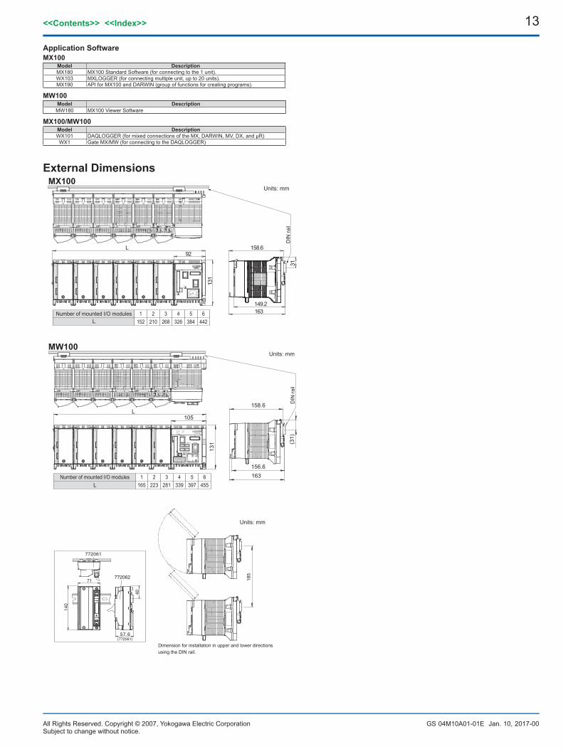
MW100
MX100ExternalDimensions
L92
163149.2
158.6
131
31D
IN ra
il
Units: mm
Number of mounted I/O modulesL
1152
2210
3268
4326
5384
6442
105
158.6
131
163156.6
(31)
DIN
rail
DATA ACQUISITION UNITMEASURE
RECORD
SERIAL RD
ETHERNET
10BASE - T
START
100 - 240V AC
STOP
USER 2USER 1
POWER
SW ON
1 2 876543
MATH
ALARM
TERMNON OFF
SERIAL COMM 70VA MAX 50 / 60Hz
L NFG RXB RXA TXB TXASG
L
Units: mm
Number of mounted I/O modulesL
1165
2223
3281
4339
5397
6455
Units: mm
Dimension for installation in upper and lower directions using the DIN rail.
71
140
40
57.6(772061)
772061
772062 185
ApplicationSoftwareMX100
Model DescriptionMX180 MX100 Standard Software (for connecting to the 1 unit).WX103 MXLOGGER (for connecting multiple unit, up to 20 units).MX190 API for MX100 and DARWIN (group of functions for creating programs).
MW100Model Description
MW180 MX100 Viewer Software
MX100/MW100Model DescriptionWX101 DAQLOGGER (for mixed connections of the MX, DARWIN, MV, DX, and µR)WX1 Gate MX/MW (for connecting to the DAQLOGGER)
Subject to change without notice.


![Interval Notation: ], not interval notationpgrant.weebly.com/uploads/2/3/2/7/23274454/6.3b_interval_notation.… · •Interval Notation: Uses different brackets to indicate an interval](https://img.pdfslide.us/doc/110x75/5f8344624904df613146ef90/interval-notation-not-interval-ainterval-notation-uses-different-brackets.jpg)