Embed Size (px)
Citation preview

Since 1991
Fuel Cell Test System Battery Charge/Discharge Cycler
Potentiostat/Galvanostat Multichannel Potentiostat/Galvanostat
Product Catalog


1
Company Profile
Since its establishment in 1991, WonATech has concentrated its efforts in the development of products related to electrochemical application. Steadily supplying products in experimental research fields and industrial sites, we have been playing a leading role in this field of business. With the constant effort to achieve excellent quality and competitive edge of our products, we have been designing high value added system equipments as follows;
1) Potentiostat/Galvanostat - Single and Multichannel Potentiostat/Galvanostat - Portable Potentiostat - W/Relevant Software
2) Battery Cycler System - For Primary & Secondary Batteries - For Super capacitors - W/Relevant Software
3) Fuel Cell Test Station - Variable Fuel Cell Supports; PEM, DMFC etc. - Fuel Cell Electronic Loads - W/Relevant Software
4) Cell & Accessories
To fulfill customer’s specific needs, we also provide flexible solution to meet their requirement with customized instruments. With base of past 16 year sales and marketing know-how, we are providing our products not only to local customers but also to foreign customers by strategic alliance with the specialized companies in each country. We hope that we satisfy your continued interest and support in the future.
Facilities
Complete 11,000 square foot facilities including sales, administrative, marketing, R & D center and manufacturing with clean room facility, test and demonstration lab, office and seminar room etc.
History
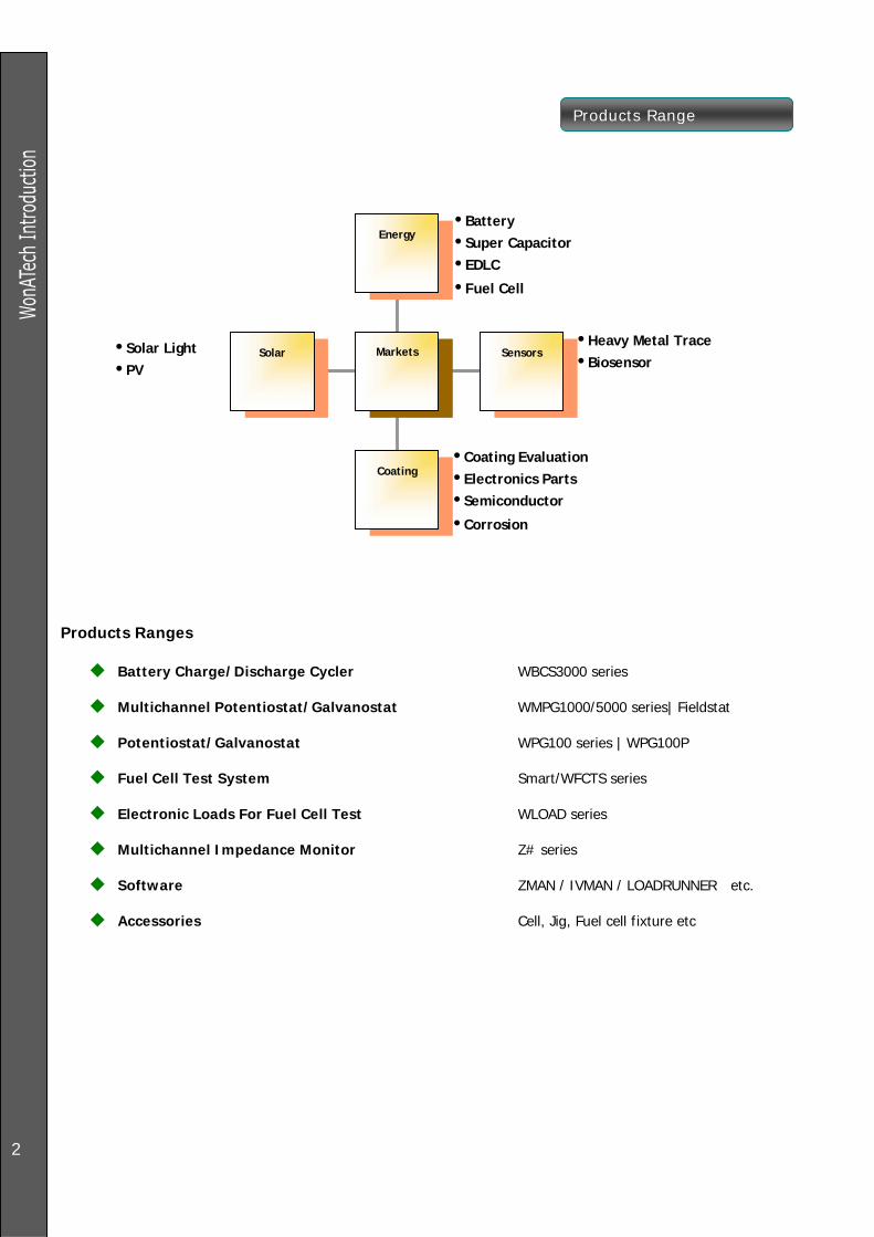
Products Range
2
Products Ranges
Battery Charge/Discharge Cycler WBCS3000 series
Multichannel Potentiostat/Galvanostat WMPG1000/5000 series| Fieldstat
Potentiostat/Galvanostat WPG100 series | WPG100P
Fuel Cell Test System Smart/WFCTS series
Electronic Loads For Fuel Cell Test WLOAD series
Multichannel Impedance Monitor Z# series
Software ZMAN / IVMAN / LOADRUNNER etc.
Accessories Cell, Jig, Fuel cell fixture etc
Solar
Coating
Sensors
Energy
Markets
•Battery •Super Capacitor •EDLC
•Fuel Cell
•Heavy Metal Trace •Biosensor
•Coating Evaluation •Electronics Parts •Semiconductor
•Corrosion
•Solar Light •PV

WBCS 3000
3
Battery Test Fuel Cell Test Pulse charge/discharge; option USB control as option Universal Graphic function And more & more …….
Feature
Potentiostat/galvanostat circuit No switching time (charging to discharging,
discharging to charging) Analog feedback control to keep constant voltage &
current Capability of electrochemical experiments by
controlling voltage versus reference electrode for positive voltage polarity only.(For +/- voltage range application, choose WMPG series multichannel potentiostat/Galvanostat
High precision
16bit(0.0015% full scale) ADC, DAC 3 current ranges (automatic/manual selection) MOSFET type linear power supply circuit. Shield cell cable to prevent EMI noise
Safety
Unique “Fail check” function: Automatic stop when measured value is different from control value by battery failure or wrong cell connection etc. => To protect system and cell. E.g. Control value: 1Amp Measured value: 500mA then automatic stop the channel
System safety parameter: If the measured value is over system specification, Automatic stop the running channel
User defined safety condition setting: User can input safety level following test cell’s chemistry.
Automatic cell connection check: Before experiment, if the cell voltage value is near 0Volt, program gives the warning message for the operator to check the cell connection.
If operator did press stop function button by mistake, confirmation message box appears.
To prevent over current, poly-switch is located in each channel
Watchdog function: Stop “running channel(s)” on communication Failure.
While any channel is running, operator could not close the server program
If main program was down by unstable operating system, independent server program keeps the experiment (control & data acquisition) without dead time.
Maintenance & System expansion
Plug-In type channels or slave style Power supply per 8channel(WBCS300S/M) Easy expansion by adding plug in channel or by
adding 8ch substation Capability of configuring each channel by different
voltage and/or current specifications Each channel has Poly switch instead of fuse.
Option Auxiliary voltage & Temperature measurement
User can assign any temperature input or auxiliary voltage input to single or multiple channel(s) data set by his/her demand.
Customized auxiliary voltage range and temperature range is available.
Current pulse Capability (GSM/CDMA
application):
Bi-polar current pulse available Max. 10 stages.
Battery jigs
Universal Jig Lithium polymer battery Jig Front Panel Jig (For type “B” only)
Front Panel type “B”

WBCS 3000
4
System configuration
Max. Channel number: 64ch/PC; 16ch/PC (pulse mode)
1) Standard type
Max. Power: 50Watt
Max. Current range: +/-5A f.s @ 5V
Min. current range: +/-10uA f.s
Max. Voltage range: +40V @500mA
Type B
Standard Type
2) Low current type
Max. Current range: +/-5mA f.s
Min. current range: +/-100nA f.s
Max. Voltage range: +/-10V
3) Medium Power type
Max. Power: 400Watt
8channel System:WBCS3000M2(Max200Watt)
4channel Slave
2channel Slave(Max 400Watt)
Dual channel Slave
16channel system
WBCS3000M2(Max200Watt per channel)
4) High Power type
Slave Style
Max Power: 4KWatt
Max. Current range: +/-200A
Max. Voltage range: +/-40V
CCU or Substation is needed.

5
WBCS 3000
System configuration example
1) Standard type mixing
8channel system: 10V, 1Amp 3ch + 5V, 2A 1ch, 7V, 100mA
4ch
Standard Substation + standard PIG 8set
2) Standard type & Low current type mixing
8channel system: 5V 1Amp 5ch, 10V, 1mA 3ch
Standard Substation + standard PIG 5set + Low current
PIG 3set
3) Standard type, Medium Power type and High power type mixing
8channel system: 5V 1Amp 4ch, 10V, 5A 2ch, 20V, 10A 2ch
Standard Substation + standard PIG 4set + Extension card
4ea + High Slave 2set + dual Slave 1set
4) High Power type & Medium Power type mixing
8channel system:
20V 10Amp 4ch, 10V, 20A 2ch, 5V, 10A 2ch
CCU controller + High Slave 6set + dual Slave 1set
8 channel CCU controller

WBCS 3000 Software
6
32bit multi-tasking
Tool bar: quick access for easy operation
WYSIWYG graphics
User friendly software
Virtual control panel........
BCO(Button click operation); User can do any task
with just clicking the button:
Easy assignment of cycle test condition file to channel
with combo box selection at anytime.
Synchronized change function of cycle test condition
file for selected multiple channels.
Real time dual channel(V & I) strip chart display for
selected channel or for all running channels with
time scrolling mode or whole window mode.
Status bar displays channel status.
Various task function: run, stop, suspend, moving step
etc..
Spying the contents of test program which assigned to
channel
Assign temperature, AuxV and CalcV channel on virtual
control panel
Test Program One stop test condition creation/modification Parameter mixed input system Unlimited number of test steps Control values are voltage(CV), current(CC), power(CP),
rest, C-rate, I.
Step flow are defined by next step, Loop and cycle Cut-off conditions can be set by;
time, voltage, current, dV/dt, dI/dt, percentage capacity(FCC, FCD, LCC, LCD), cycle time, capacity, -dV, power, temperature, Aux voltage, Calc voltage, dT/dt, Loop time, EocV
Data sampling condition by each step : time, dV/dt, dI/dt, dT/dt, dV2/dt
And/Or logic in cut-off condition setting Menu Selection(Pre-defined techniques)
Lithium battery application mode menu
CC charging/discharging mode menu

WBCS 3000 Software
7
Pulse Capability(GSM/CDMA application): Option Parameter Input
Oscilloscope capture
Pulse test data(option)
Simple Monitor
Real time display: time, voltage, current, channel status
channel status color display: charging, discharging, standby, idle, calibration
Always activated window(This widow does not hidden)
Can be located outside of main program window. Detailed Monitor
displayed test data: status, running time, step number, cycle number, step time, current range, current, voltage, capacity, power, energy, Aux V, Calc V, temp, cycle file name, data file name, file size.
Detailed monitor type selection: All channels, running channels only, grouped channels
Activated character only for running channels.
Grouping
Classification/Grouping each channels by users
purpose
Labeling each group by operator name, chemistries
etc. Group monitoring available by this setting. Graphics
Multiple plot formats
- General Graph
- Cycle Graph
- Step Graph

WBCS 3000 Software
8
User can define axis with specified parameters under each graph format.
General graph format
Current-Voltage vs. time graph
Current-voltage vs. cycle time graph
Cycle graph format
charging capacity-discharging capacity vs. cycle number graph
Real time plotting

WBCS 3000 Software
9
Step graph format
dQ/dV vs. Voltage graph(EVS)
General Function of Graph
DQ/dV vs. Voltage Voltage vs. charging time Voltage vs. discharging time Voltage vs. charging Capacity(discharging capacity) Voltage vs. capacity etc.. Plot overlay: Max. 10 plot Universal Graphics: Any combination of X,Y,Y1 axis
parameters Automatic updating plot with reloading button for
running channel data Automatic/Manual scale and polarity selection for each
axis Cross hair pointer by mouse click/arrow key displays
coordinate values Mouse zooming Text insertion on graph Copy to Clipboard for usage in other application
software Slope calculation
Grid On/Off and dot/line selection Parameter change without reloading the data file Data set On/Off: Data can be visible or invisible by
selecting/ deselecting the data set. ASCII file conversion of graph data only
Voltage vs. charging-discharging time graph
Voltage vs. |charging-discharging capacity| graph
Cyclic voltammogram
Tafel graph

10
WBCS 3000
Reporting
General data report Cycle data report Capacity data report Step data report Calibration data report Test program report Automatic documentation; running time, Test
memo, operator name, weight, test I.D etc. Calibration
4 points calibration for voltage and each current
ranges Check-out function with calibrated data for
confirming accuracy Calibrates a channel while other channels are
running To prevent wrong-calibration, error warning displays
when error happens. Linear calibration for + & - polarity with one
procedure Store & Backup calibration data
Filing
Create Potentiostat/Galvanostat mode or potentiostat mode test program file(Dual mode)
ASCII file conversion(TAB, comma, space delimited) of general data, cycle data, capacity data and step data
Maximum file size: 2GB Split general data by cycle number Max. Data file name: 15char + channel
number(3digit) Safety.
Double safety check: Automatically stop the test run if the voltage /current/ temperature exceed the hardware specification or safety limit setting value on test program
Fail function: If the measurement value is different from control value, the test is stopped by fail check
function in order to protect the cell and/or system failure.
Each channel has its own fuse to protect over current or voltage
While any channel is running, operator could not close the server program
Automatic cell mount detection Misc
Closing function of all activated windows Dual time input mode(9999sec or hh:mm:ss) Independent server program English version & Korean version available
System Requirement
Operating system: Windows2000/XP Processor: Pentium3 or above RAM: 128MB or above VGA: 800 x 600 or above Interface: PCI bus Mouse Printer: most printers/plotters supported by Windows.
(Color printer/plotter recommended)

11
WMPG series
Corrosion Test Sensor application Electro-analytical application Battery/Fuel cell Test Electroplating, Electro-synthesis Electrochemical permeation 5 current ranges(WMPG5000) &
3 current ranges(WMPG1000) Customize specification available
System hardware was designed for stable and accurate instrument furthermore for easy expansion and maintenance. So WMPG series choose plug-in type module with independent power suppliers per 8ch substation. Each substation can be used as independent system with optional “Stand Alone Kit” or can be built up integrated system as add-on. These give flexibility to users application.
For stable and accurate target
4 probe type true potentiostat/galvanostat circuit High resolution 16 bit ADC/DAC: WMPG provides
0.0015% f.s resolution in control and acquisition both.
Channel isolation: To prevent any noise from the other channel, each channel is designed for isolation.
Multiple current ranges (WMPG1000: 3 ranges, WMPG5000: 5 ranges): This improves the resolution and accuracy in control and measurement of current. Auto/manual selection
For easy expansion/maintenance target
Channel Plug-in module: Plug-in module is easily upgradeable or modifying voltage/current range. Also if one channel is out of order, Just replacement is easiest way to clean the problem. Option module is plug-in type too. It means upgrade is very easy. For one board type per 8 channels, if one channel is out of order, user cannot use all 8 channels.
Substation add-on type: WMPG series can expand the channels up to 64 channels per system. When the user wants to expand the channels, he/she just adds the substation. One of modular system’s advantages is maintenance. If one substation is out of order in power supplier’s part, the other substations can be run without dead time.
WMPG5000 Software
Application Cyclic voltammetry (Technique Menu) Linear Sweep Voltammetry (Technique Menu) Square Wave Voltammetry (Technique Menu:
Option) Chrono-amperometry (Technique Menu) Chrono-coulometry (Technique Menu) Chrono-potentiometry (Technique Menu) Tafel Plot (Technique Menu) Potentiodynamic (Technique Menu) Cyclic Polarization (Technique Menu) Ecorr vs. time (Technique Menu) Galvanodynamic OCV measurement Zero resistance Ammeter Linear polarization resistance (Technique
Menu) Rp-Ec trend Charge/discharge Battery test Electrochemical Voltage Spectroscopy (EVS) Galvanic Intermittent time technique (GITT) Electrochemical Permeation User defined techniques
Virtual control panel
BCO (Button click operation); User can do any task with just clicking the button: NO MENU SELECTION
Easy assignment of cycle test condition file to channel with combo box selection at anytime.
Synchronized change function of cycle test condition file for selected multiple channels.
Real time dual channel (V & I) strip chart display for selected channel or for all running channels with time scrolling mode or whole window mode.
Status bar displays channel status. Booking running channel stop function by time, cycle
number, step etc.
WMPG series
12
Various task function: run, stop, suspend, moving
step etc. Spying the contents of test program which assigned
to channel Assign temperature, AuxV and CalcV channel on
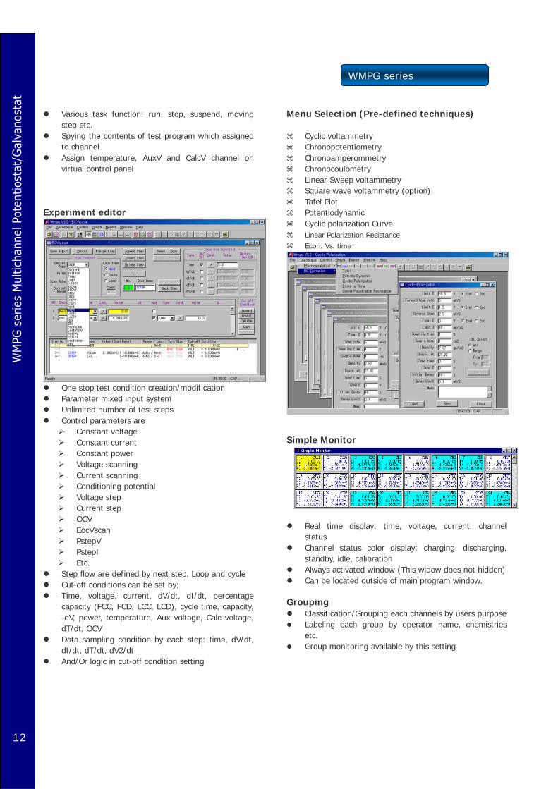
virtual control panel Experiment editor
One stop test condition creation/modification Parameter mixed input system Unlimited number of test steps Control parameters are
Constant voltage Constant current Constant power Voltage scanning Current scanning Conditioning potential Voltage step Current step OCV EocVscan PstepV PstepI Etc.
Step flow are defined by next step, Loop and cycle Cut-off conditions can be set by; Time, voltage, current, dV/dt, dI/dt, percentage
capacity (FCC, FCD, LCC, LCD), cycle time, capacity, -dV, power, temperature, Aux voltage, Calc voltage, dT/dt, OCV
Data sampling condition by each step: time, dV/dt, dI/dt, dT/dt, dV2/dt
And/Or logic in cut-off condition setting
Menu Selection (Pre-defined techniques)
Cyclic voltammetry Chronopotentiometry Chronoamperommetry Chronocoulometry Linear Sweep voltammetry Square wave voltammetry (option) Tafel Plot Potentiodynamic Cyclic polarization Curve Linear Polarization Resistance Ecorr. Vs. time
Simple Monitor
Real time display: time, voltage, current, channel
status Channel status color display: charging, discharging,
standby, idle, calibration Always activated window (This widow does not hidden) Can be located outside of main program window.
Grouping
Classification/Grouping each channels by users purpose Labeling each group by operator name, chemistries
etc. Group monitoring available by this setting
WMPG series
13
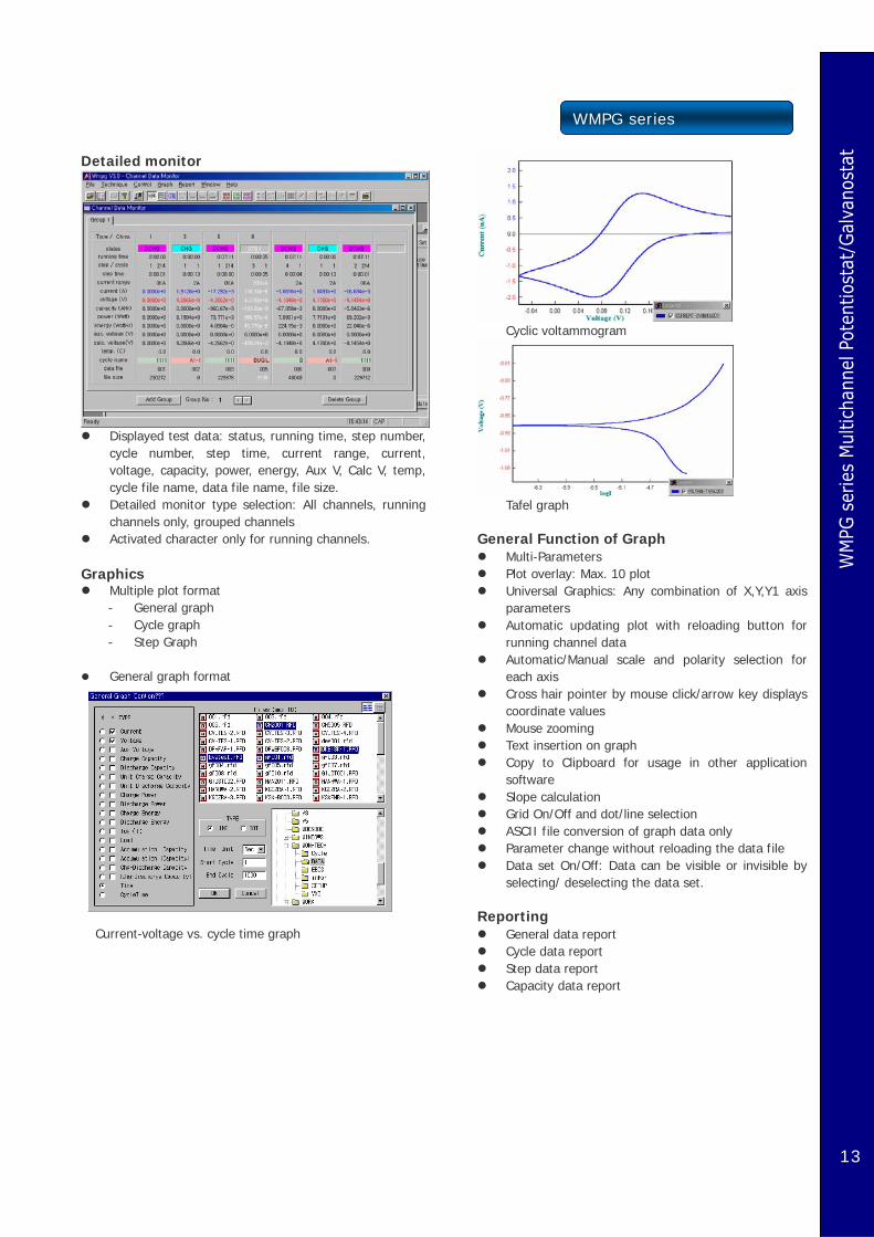
Detailed monitor
Displayed test data: status, running time, step number,
cycle number, step time, current range, current, voltage, capacity, power, energy, Aux V, Calc V, temp, cycle file name, data file name, file size.
Detailed monitor type selection: All channels, running channels only, grouped channels
Activated character only for running channels.
Graphics Multiple plot format - General graph - Cycle graph - Step Graph
General graph format
Current-voltage vs. cycle time graph
Cyclic voltammogram
Tafel graph
General Function of Graph
Multi-Parameters Plot overlay: Max. 10 plot Universal Graphics: Any combination of X,Y,Y1 axis
parameters Automatic updating plot with reloading button for
running channel data Automatic/Manual scale and polarity selection for
each axis Cross hair pointer by mouse click/arrow key displays
coordinate values Mouse zooming Text insertion on graph Copy to Clipboard for usage in other application
software Slope calculation Grid On/Off and dot/line selection ASCII file conversion of graph data only Parameter change without reloading the data file Data set On/Off: Data can be visible or invisible by
selecting/ deselecting the data set. Reporting
General data report Cycle data report Step data report Capacity data report
14
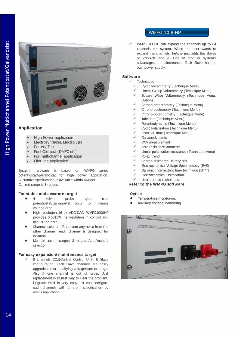
WMPG 1000HP
Application
High Power application Electrosynthesis/Electrolysis Battery Test Fuel Cell test (DMFC etc) For multichannel application Pilot line application
System hardware is based on WMPG series potentiostat/galvanostat for high power application. Customize specification is available within 4KWatt. Current range is 3 ranges. For stable and accurate target
4 kelvin probe type true potentiostat/galvanostat circuit to minimize voltage drop
High resolution 16 bit ADC/DAC: WMPG1000HP provides 0.0015% f.s resolution in control and acquisition both.
Channel isolation: To prevent any noise from the other channel, each channel is designed for isolation.
Multiple current ranges: 3 ranges. Auto/manual selection
For easy expansion/maintenance target
8 channels CCU(Central Control Unit) & Slave configuration. Each Slave channels are easily upgradeable or modifying voltage/current range. Also if one channel is out of order, Just replacement is easiest way to clear the problem. Upgrade itself is very easy. It can configure each channels with different specification by user’s application
WMPG1000HP can expand the channels up to 64 channels per system. When the user wants to expand the channels, he/she just adds the Slaves or 2ch/4ch module. One of modular system’s advantages is maintenance. Each Slave has its own power supply.
Software
Techniques Cyclic voltammetry (Technique Menu) Linear Sweep Voltammetry (Technique Menu) Square Wave Voltammetry (Technique Menu:
Option) Chrono-amperometry (Technique Menu) Chrono-coulometry (Technique Menu) Chrono-potentiometry (Technique Menu) Tafel Plot (Technique Menu) Potentiodynamic (Technique Menu) Cyclic Polarization (Technique Menu) Ecorr vs. time (Technique Menu) Galvanodynamic OCV measurement Zero resistance Ammeter Linear polarization resistance (Technique Menu) Rp-Ec trend Charge/discharge Battery test Electrochemical Voltage Spectroscopy (EVS) Galvanic Intermittent time technique (GITT) Electrochemical Permeation User defined techniques
Refer to the WMPG software Option
Temperature monitoring. Auxiliary Voltage Monitoring

WMPG1000s
15
Application
Low current application Sensor application Electroanalytical application Micro battery application Compact size Multi working electrodes, single reference
& single counter electrode Max. 64channel control per PC And more…
System hardware is based on WMPG series multichannel potentiostat/galvanostat. The system contains independent channel controller, a multiplexed data acquisition circuitry. This system can provide two mode(General mode: general multichannel potentiostat/galvanostat with eight working electrodes, eight reference electrodes and eight counter electrodes or Sensor mode: a multi-potentiostat with eight working electrodes, one common reference electrode and one common counter electrode). The sensor mode is designed so that eight working electrodes are in the same electrochemical cell. The potential control range is following customer specification. Each electrode can be individually controlled, including on/off control, potential and current range settings.. Each substation can be used as independent system with optional “Stand Alone Kit” or can be built up integrated system as add-on. These give flexibility to users application. For stable and accurate target
4 probe type true potentiostat/galvanostat circuit High resolution 16 bit ADC/DAC: WMPG provides
0.0015% f.s resolution in control and acquisition both.
Channel isolation: To prevent any noise from the other channel, each channel is designed for isolation.
Multiple current ranges: 3 ranges. Auto/manual selection
Software
Application Cyclic voltammetry (Technique Menu) Linear Sweep Voltammetry (Technique Menu) Square Wave Voltammetry (Technique Menu:
Option) Chrono-amperometry (Technique Menu) Chrono-coulometry (Technique Menu) Chrono-potentiometry (Technique Menu) Tafel Plot (Technique Menu)
Potentiodynamic (Technique Menu) Cyclic Polarization (Technique Menu) Ecorr vs. time (Technique Menu) Galvanodynamic OCV measurement Zero resistance Ammeter Linear polarization resistance (Technique
Menu) Rp-Ec trend Charge/discharge Battery test Electrochemical Voltage Spectroscopy (EVS) Galvanic Intermittent time technique (GITT) Electrochemical Permeation User defined techniques
Virtual control panel
BCO (Button click operation); User can do any task with just clicking the button: NO MENU SELECTION
Easy assignment of cycle test condition file to channel with combo box selection at anytime.
Synchronized change function of cycle test condition file for selected multiple channels.
Real time dual channel (V & I) strip chart display for selected channel or for all running channels with time scrolling mode or whole window mode
Status bar displays channel status. Booking running channel stop function by time, cycle number, step etc.
with coulometer option

16
FieldStat
Application
For Field Application Sensor application Electroanalytical application Micro battery application Field Corrosion measurement Solar cell test Max. 8channel system Notebook PC is not included
System hardware is based on WMPG series multichannel potentiostat/galvanostat. The system contains independent channel controller, a multiplexed data acquisition circuitry. This system was designed for field usage. Customize specification is available within 2Watt per channel. This system is true multichannel potentiostat/Galvanostat so each channel works independently. Standard function is based on general multichannel potentiostat/galvanostat with eight working electrodes, eight reference electrodes and eight counter electrodes but multi-working electrode system for Sensor application (a multi-potentiostat with eight working electrodes, one common reference electrode and one common counter electrode) is available. Please contact with your regional distributor. The sensor mode is designed so that eight working electrodes are in the same electrochemical cell. The potential control range is following customer specification. Each electrode can be individually controlled, including on/off control, potential and current range settings... For stable and accurate target
4 probe type true potentiostat/galvanostat circuit High resolution 16 bit ADC/DAC: WMPG provides
0.0015% f.s resolution in control and acquisition both.
Channel isolation: To prevent any noise from the other channel, each channel is designed for isolation.
Multiple current ranges: 3 ranges. Auto/manual selection
Software
Application Cyclic voltammetry (Technique Menu) Linear Sweep Voltammetry (Technique Menu) Square Wave Voltammetry (Technique Menu:
Option) Chrono-amperometry (Technique Menu) Chrono-coulometry (Technique Menu) Chrono-potentiometry (Technique Menu)
Tafel Plot (Technique Menu) Potentiodynamic (Technique Menu) Cyclic Polarization (Technique Menu) Ecorr vs. time (Technique Menu)
Galvanodynamic OCV measurement Zero resistance Ammeter Linear polarization resistance (Technique Menu) Rp-Ec trend Charge/discharge Battery test Electrochemical Voltage Spectroscopy (EVS) Galvanic Intermittent time technique (GITT) Electrochemical Permeation User defined techniques
Virtual control panel
BCO (Button click operation); User can do any task with just clicking the button: NO MENU SELECTION
Easy assignment of cycle test condition file to channel with combo box selection at anytime.
Synchronized change function of cycle test condition file for selected multiple channels.
Real time dual channel (V & I) strip chart display for selected channel or for all running channels with time scrolling mode or whole window mode
Status bar displays channel status. Booking running channel stop function by time, cycle number, step etc.
Option
DC/AC convertor for power supply. Notebook PC Low current version for sensor application is
available

17
WPG series
Application
Battery/Micro Fuel cell Membrane Corrosion Sensor Photo electrochemistry Electrosynthesis/Electrolysis User defined El-Chem. application
Feature
Economical Price 16bit ADC, DAC For long term experiment Accurate Control & Measurement Easy to control Software Free Software upgrade Importing/Exporting data file
Hardware
With 16bit ADC, DAC, this system provides 0.0015% f.s high resolution in control and data acquisition.
6 current ranges (Automatic & manual setting) User specification is available from low current to high
current Output terminal: V-out & I-out analog signal for XY
recorder High accuracy: < 0.01% f.s (standard type) Automatic protection: This system automatically stops
the experiment if it meets data over hardware specification.
This system can be used for battery cycler This system use I/O interface instead of serial
communication, this system can be used long-term experiment and stable control and data acquisition.
Software
This system provide pre-defined techniques menu and universal test procedure menu for user to make their
own experiment procedure with cycle, loop and and or logic
Predefined Technique Menu
Electroanalytical techniques Cyclic voltammetry Linear Sweep Voltammetry Chrono-amperometry Chrono-coulometry Chrono-potentiometry Square wave Voltammetry
Corrosion Measurement
Tafel Plot Potentiodynamic Cyclic polarization Ecorr vs. Time Linear polarization Resistance
Universal Test Mode
Electrochemical Voltage Spectroscopy (EVS) Galvanic Intermittent time technique (GITT) Battery Cycling User definable Techniques Potentiostat Mode/ Cycler Mode Universal test mode

18
WPG series
Unlimited step experiment available
Control type: voltage, current, power, load, rest, C-rate, current scan, voltage scan, conditioning potential, voltage step, current step, rest conditioning, Last I, Last V, OCV, LastVscan, VocScan, ZRA.
Cut-Off (Vertex); time, voltage, current, dV/dt, dI/dt, percentage capacity (FCC, FCD, LCC, LCD), cycle time, capacity, -dV, power, temperature, Aux voltage, Calc voltage, dT/dt
Data acquisition setting: time, dV/dt, dI/dt, dT/dt, dV2/dt
And/Or logic available in cut-off condition
Virtual control panel
In virtual control panel, it displays real time graphics (V vs. I, V & I vs. time, V vs. logI etc) to fit its own techniques. It also displays current data and other information of current experiment
Experiment parameters can be saved or loaded on the virtual control panel.
On experiment running, users can data analysis or other tasking simultaneously.
Nominate data saving folder by user selection
Cell connection check function.
Safety limit & Fail check function.
To protect hardware, this system stop the experiment run automatically when detect the any value over hardware specification or user defined safety value
It also stop the experiment running when the control value is different from measured value by wrong connection or abnormal reference electrode etc
If the user try to close the program by mistake operation, the program refuse this operation
This system monitor the cell voltage and if the voltage value is too small, then warning message will be display to protect wrong cell connection
Graphics Universal Graphic function: User can set X, Y, Y1 axis
variable User can use this function for running experiment data at
real time.
With re-load button click, the data format can be
changed with out data loading
File overlay: Max. 10 files Automatic scaling and manual scale/polarity setting
available Crosshair data pointing displays the data value by mouse
click Caption available on the graph Copy to clip board for graphic data. Slope calculation function Grid and pixel/line selection Data conversion only for graph data
Option Temperature measurement Auxiliary voltage measurement
WPG100e Economical version
19
WPG100HP series
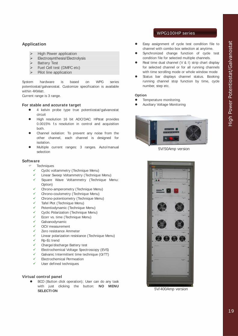
Application
High Power application Electrosynthesis/Electrolysis Battery Test Fuel Cell test (DMFC etc) Pilot line application
System hardware is based on WPG series potentiostat/galvanostat. Customize specification is available within 4KWatt. Current range is 3 range. For stable and accurate target
4 kelvin probe type true potentiostat/galvanostat circuit
High resolution 16 bit ADC/DAC: HPstat provides 0.0015% f.s resolution in control and acquisition both.
Channel isolation: To prevent any noise from the other channel, each channel is designed for isolation.
Multiple current ranges: 3 ranges. Auto/manual selection
Software
Techniques Cyclic voltammetry (Technique Menu) Linear Sweep Voltammetry (Technique Menu) Square Wave Voltammetry (Technique Menu:
Option) Chrono-amperometry (Technique Menu) Chrono-coulometry (Technique Menu) Chrono-potentiometry (Technique Menu) Tafel Plot (Technique Menu) Potentiodynamic (Technique Menu) Cyclic Polarization (Technique Menu) Ecorr vs. time (Technique Menu) Galvanodynamic OCV measurement Zero resistance Ammeter Linear polarization resistance (Technique Menu) Rp-Ec trend Charge/discharge Battery test Electrochemical Voltage Spectroscopy (EVS) Galvanic Intermittent time technique (GITT) Electrochemical Permeation User defined techniques
Virtual control panel
BCO (Button click operation); User can do any task with just clicking the button: NO MENU SELECTION
Easy assignment of cycle test condition file to channel with combo box selection at anytime.
Synchronized change function of cycle test condition file for selected multiple channels.
Real time dual channel (V & I) strip chart display for selected channel or for all running channels with time scrolling mode or whole window mode
Status bar displays channel status. Booking running channel stop function by time, cycle number, step etc.
Option
Temperature monitoring. Auxiliary Voltage Monitoring
5V/50Amp version
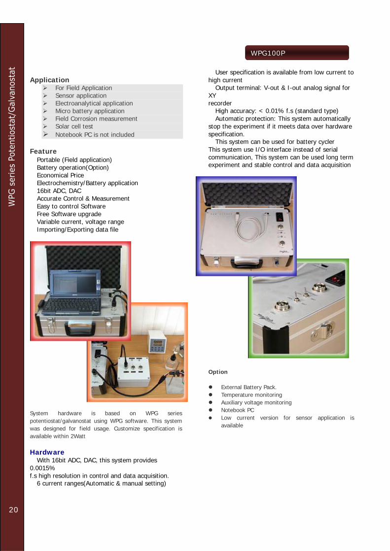
5V/400Amp version
20
WPG100P
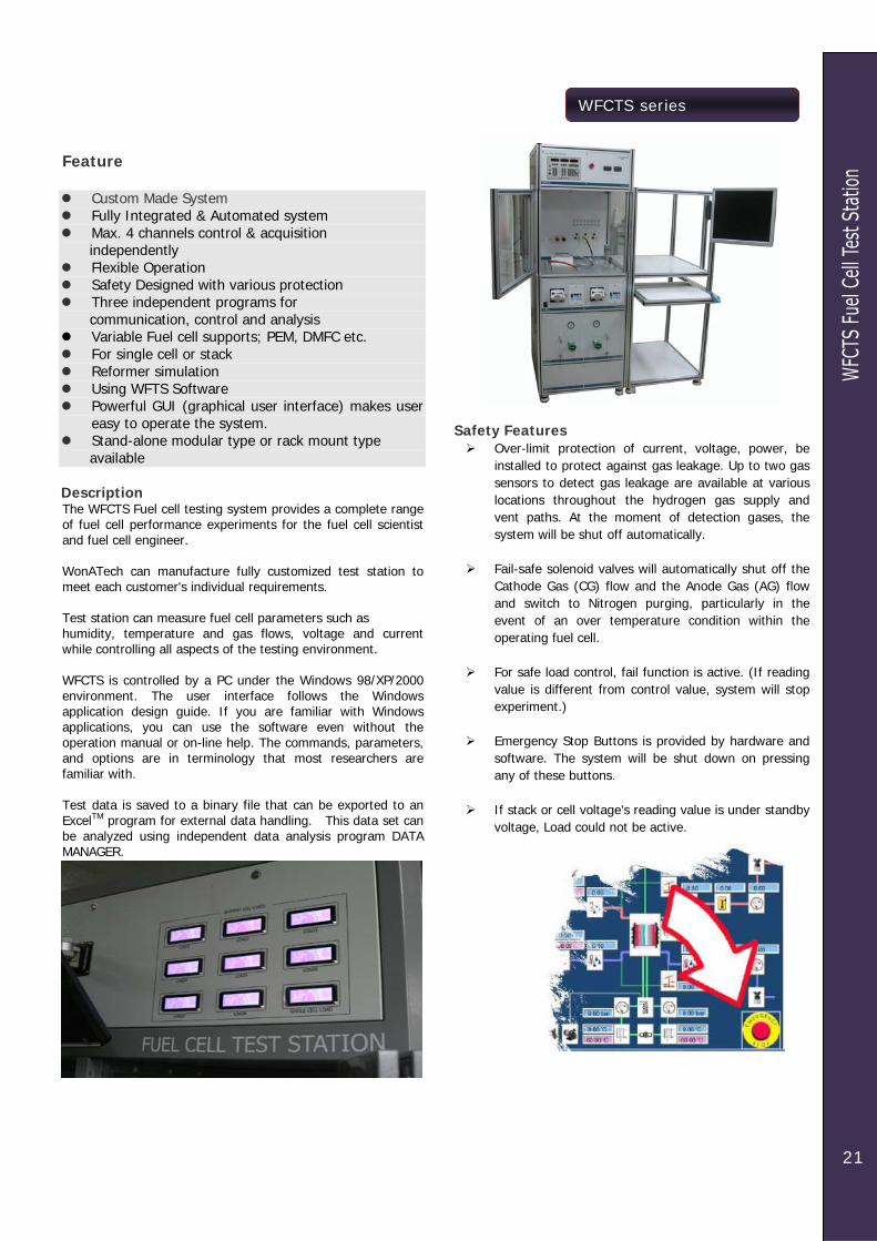
Application
For Field Application Sensor application Electroanalytical application Micro battery application Field Corrosion measurement Solar cell test Notebook PC is not included
Feature � Portable (Field application) � Battery operation(Option) � Economical Price � Electrochemistry/Battery application � 16bit ADC, DAC � Accurate Control & Measurement � Easy to control Software � Free Software upgrade � Variable current, voltage range � Importing/Exporting data file
System hardware is based on WPG series potentiostat/galvanostat using WPG software. This system was designed for field usage. Customize specification is available within 2Watt Hardware � With 16bit ADC, DAC, this system provides 0.0015% f.s high resolution in control and data acquisition. � 6 current ranges(Automatic & manual setting)
� User specification is available from low current to high current � Output terminal: V-out & I-out analog signal for XY recorder � High accuracy: < 0.01% f.s (standard type) � Automatic protection: This system automatically stop the experiment if it meets data over hardware specification. � This system can be used for battery cycler This system use I/O interface instead of serial communication, This system can be used long term experiment and stable control and data acquisition
Option
External Battery Pack. Temperature monitoring Auxiliary voltage monitoring Notebook PC Low current version for sensor application is
available
21
WFCTS series
Feature
Custom Made System Fully Integrated & Automated system Max. 4 channels control & acquisition
independently Flexible Operation Safety Designed with various protection Three independent programs for
communication, control and analysis Variable Fuel cell supports; PEM, DMFC etc. For single cell or stack Reformer simulation Using WFTS Software Powerful GUI (graphical user interface) makes user
easy to operate the system. Stand-alone modular type or rack mount type
available Description The WFCTS Fuel cell testing system provides a complete range of fuel cell performance experiments for the fuel cell scientist and fuel cell engineer. WonATech can manufacture fully customized test station to meet each customer's individual requirements. Test station can measure fuel cell parameters such as humidity, temperature and gas flows, voltage and current while controlling all aspects of the testing environment. WFCTS is controlled by a PC under the Windows 98/XP/2000 environment. The user interface follows the Windows application design guide. If you are familiar with Windows applications, you can use the software even without the operation manual or on-line help. The commands, parameters, and options are in terminology that most researchers are familiar with. Test data is saved to a binary file that can be exported to an ExcelTM program for external data handling. This data set can be analyzed using independent data analysis program DATA MANAGER.
Safety Features
Over-limit protection of current, voltage, power, be installed to protect against gas leakage. Up to two gas sensors to detect gas leakage are available at various locations throughout the hydrogen gas supply and vent paths. At the moment of detection gases, the system will be shut off automatically.
Fail-safe solenoid valves will automatically shut off the
Cathode Gas (CG) flow and the Anode Gas (AG) flow and switch to Nitrogen purging, particularly in the event of an over temperature condition within the operating fuel cell.
For safe load control, fail function is active. (If reading
value is different from control value, system will stop experiment.)
Emergency Stop Buttons is provided by hardware and
software. The system will be shut down on pressing any of these buttons.
If stack or cell voltage's reading value is under standby
voltage, Load could not be active.

22
WFCTS Software
System Configuration
By expanding system controller, one control PC can manage Max. 4channels with full optional equipments.
Easy to expand system configuration by adding proper optional equipments. Each channel's configuration can be different by user's purpose The system can be equipped into rack or independent modular chassis. For gas reformation, Max. Fuel gas line is 5, Max. oxidant gas line is 2 Nitrogen gas flowing path thru MFC or without MFC is available PC controllable heating power on/off is available.
Standard Configuration List-(For PEMFC)
- Solenoid valve: 3ea - MFC for Anode and Cathode - Check valve: 4ea - 3 Way valve: 2ea - Humidifier: 2ea - Automatic water feeding for humidifier: 2ea - Pressure measurement: 2ea - Back pressure regulator 2ea - Temperature controller: 7 point - Load bank: 1ea - Temperature measurement: 9 point - System controller with emergency switch - Control PC with WFTS software - Interface boards with cables
Optional Equipment List - MFC(s) for Anode and/or Cathode for Reformate - MFC for Nitrogen - Pump for DMFC - Heater Power control - Gas detectors - Temperature controller with measurement (Outlet) - Temperature measurement (Outlet) - Humidity measurement(Inlet, Outlet) - Pressure measurement(Inlet, Outlet) - Impedance Monitor - Stack heating/cooling system - Stack temperature monitor(each cell) - Stack voltage monitor(each cell) - Differential pressure gauge - Moisture trap

WFCTS
23
WFCTS_Standard
WFCTS_Custom made (example)
24
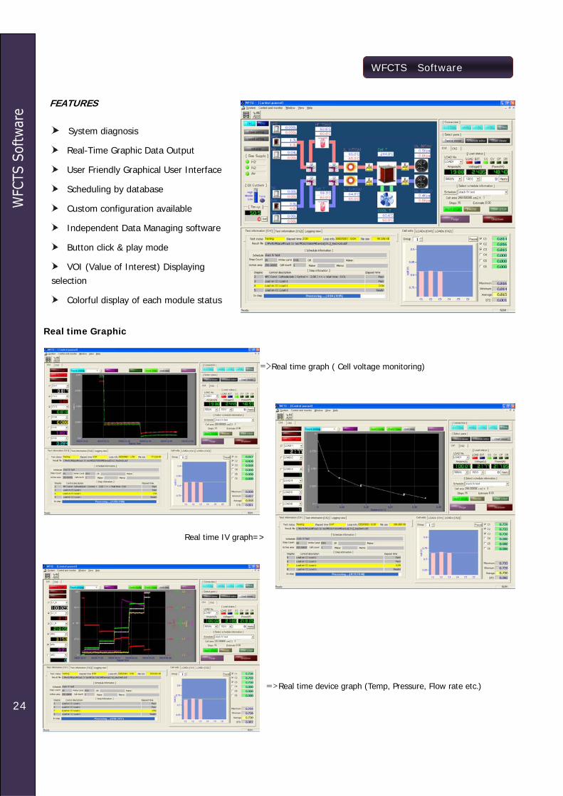
WFCTS Software
Real time Graphic =>Real time graph ( Cell voltage monitoring) Real time IV graph=> =>Real time device graph (Temp, Pressure, Flow rate etc.)
FEATURES
System diagnosis
Real-Time Graphic Data Output
User Friendly Graphical User Interface
Scheduling by database
Custom configuration available
Independent Data Managing software
Button click & play mode
VOI (Value of Interest) Displaying selection
Colorful display of each module status

25
WFCTS Software
Schedule editor
• Loop control available • Device setting • Load control • Data filing setting • Stoichiometric setting

26
Smart series
Feature Fully Integrated Compact Size Suitable for single cell(PEM,DM) Automatic purge gas control External anode & cathode line and cell
temperature control Watch-dog function Full automatic by PC control Max 4channels control by one PC Accurate electronic load Various safety functions Powerful software with independent data
analysis software Description The SMART II is very compact, however, fully automated and integrated at a very attractive price. Our control and measurement software with powerful graphical user interface makes you easy to operate the SMART II. With the exceptional features of the SMART II, you can digitize your fuel cell economically and evaluate it easily. Standard Configuration List
Solenoid valve: 3ea MFC for Anode and Cathode Check valve: 4ea 3 Way valve: 2ea Humidifier: 2ea Automatic water feeding for humidifier: 2ea Temperature controller(line heater): 4ea Load bank: 1ea Stack or cell Temperature controller: 1ea System controller with emergency switch Control PC with WFTS software Interface boards with cables
Optional Equipment List
MFC(s) for Anode and/or Cathode for Reformate MFC for Nitrogen Pump for DMFC Heater Power control Gas detectors Temperature controller with measurement
(Outlet) Temperature measurement (Outlet) Humidity measurement(Inlet, Outlet) Pressure measurement(Inlet, Outlet) Impedance Monitor Stack cooling system Stack temperature monitor(each cell) Stack voltage monitor(each cell) Differential pressure gauge Moisture trap
PEM/DM Hybrid Fuel Cell Test Station - SMART II
Hardware Specification
MFC (Mass Flow Controller), 2 ea - Max. Flow rate : H2 1slpm, Air 5slpm - Accuracy : 0.8% Full scale
100W Single Cell Application - Anode gas flow rate : 0.02 – 1 slpm - Cathode gas flow rate : 0.1 – 5 slpm
Humidifier, 2 ea - membrane type - Automatic Water feeding system(PC control)
Built-in Precision Electronic Load - 4 ranges - 5V(0.1,1,2,5V) 100A(10,20,50,100Amp)
Humidify or dry gas selectable - auto 3 way valve
Back Pressure regulator, 2ea - 0-50psi
Precision Rotary Piston Pump - 0.1 – 45ml/min - for DM application
Temperature Control System - Control & measurement - 7 points - Humidifier, Gas line(inside, outside), Cell Temp
Temperature measurement only - pipe line inside temperature : 2 points
Pressure measurement - 2 points
Compact size - 500W x 400H x 500D (mm)

27
Smart series
Smart Family SmartPEM FC test system SmartPEM FC test system for long term test
SmartDM FC test system SmartPEM custom made version
Block Diagram SmartII
28
Smart series Software
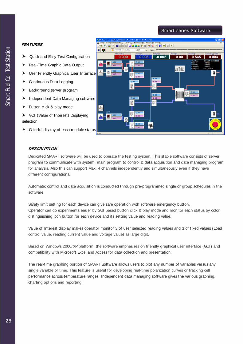
DESCRIPTION
Dedicated SMART software will be used to operate the testing system. This stable software consists of server program to communicate with system, main program to control & data acquisition and data managing program for analysis. Also this can support Max. 4 channels independently and simultaneously even if they have different configurations. Automatic control and data acquisition is conducted through pre-programmed single or group schedules in the software. Safety limit setting for each device can give safe operation with software emergency button. Operator can do experiments easier by GUI based button click & play mode and monitor each status by color distinguishing icon button for each device and its setting value and reading value. Value of Interest display makes operator monitor 3 of user selected reading values and 3 of fixed values (Load control value, reading current value and voltage value) as large digit. Based on Windows 2000/XP platform, the software emphasizes on friendly graphical user interface (GUI) and compatibility with Microsoft Excel and Access for data collection and presentation. The real-time graphing portion of SMART Software allows users to plot any number of variables versus any single variable or time. This feature is useful for developing real-time polarization curves or tracking cell performance across temperature ranges. Independent data managing software gives the various graphing, charting options and reporting.
FEATURES
Quick and Easy Test Configuration
Real-Time Graphic Data Output
User Friendly Graphical User Interface
Continuous Data Logging
Background server program
Independent Data Managing software
Button click & play mode
VOI (Value of Interest) Displaying selection
Colorful display of each module status
29
Smart series Software
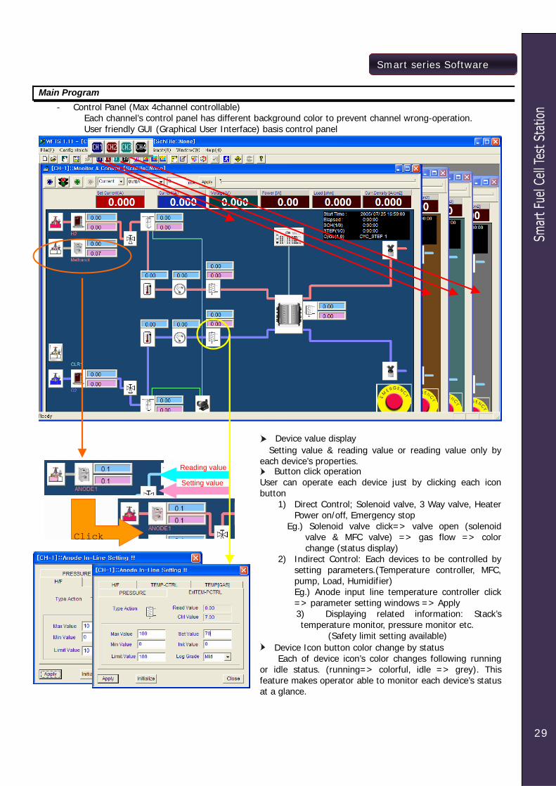
Main Program - Control Panel (Max 4channel controllable)
Each channel’s control panel has different background color to prevent channel wrong-operation. User friendly GUI (Graphical User Interface) basis control panel
Click
Reading value
Setting value
Device value display Setting value & reading value or reading value only by each device’s properties. Button click operation
User can operate each device just by clicking each icon button
1) Direct Control; Solenoid valve, 3 Way valve, Heater Power on/off, Emergency stop
Eg.) Solenoid valve click=> valve open (solenoid valve & MFC valve) => gas flow => color change (status display)
2) Indirect Control: Each devices to be controlled by setting parameters.(Temperature controller, MFC, pump, Load, Humidifier) Eg.) Anode input line temperature controller click => parameter setting windows => Apply
3) Displaying related information: Stack’s temperature monitor, pressure monitor etc.
(Safety limit setting available) Device Icon button color change by status
Each of device icon’s color changes following running or idle status. (running=> colorful, idle => grey). This feature makes operator able to monitor each device’s status at a glance.

30
Smart series Software
Real time graph setting Reference On/Off Control value scroll bar Data filing On/Off Load On/Off
VOI (Value of Interest) Fixed value (3), User’s value (3)
Click for manual control
Click for manual control during Pre-programmed schedule running
<= Cell standby voltage detection for safety operation
Load setting value
User selectable values
Voltage valueCurrent value Experiment time info
Gas detector Heater Power on/off

31
Smart series Software
Cell or Stack information
Stack Monitor
Safety Limit setting for voltage and/or temperature
Display Highest value/Lowest value during operation
Display average value
Stack standby voltage detection setting for safety operation
Back ground bar graph for each cell voltage & temperature with color.
Stack voltage/temperature monitoring
Schedule and batch file Schedule file
Batch file Batch file is a series of schedule files.
- Creating/modifying schedule file/batch file by channel ID for each channel configuration’s
difference. - WFTS software detect channel ID for proper
operation.
32
Smart series Software
- Schedule file includes Load control parameters
Constant current Constant voltage Constant power Step current Step voltage Step power Rest & Conditioning rest Current , voltage range setting
Data sampling time MFC/pump control parameters Each step’s cut-off condition
Time F-time S-time Current, voltage, power
Temperature control External program control for impedance
monitor Memo
During experiment using schedule file or batch
file, operator can change each device’s parameters and/or change load control by manually.
Operator can stop experiment by pressing stop
button or emergency stop button or click purge gas’ solenoid valve icon.
When he/she loads schedule file or batch file for
each channel and apply experiment condition by apply icon clicking then WFTS software control each device following defined parameters on first schedule file except load control. Load control is only activated when experiment is started and gas flow makes cell/stack voltage up. WFTS continuously monitors cell/stack voltage and only if the voltage is higher than setting value (on view cond voltage), it makes load control enable.
Event Logging
WFTS software records each event for history reviewing. Each logging file can be view on Data manager software.
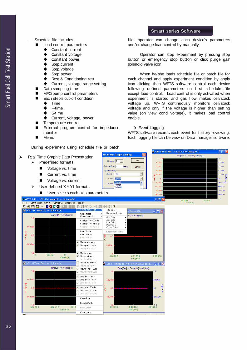
Real Time Graphic Data Presentation
Predefined formats Voltage vs. time Current vs. time Voltage vs. current
User defined X-Y-Y1 formats User selects each axis parameters.

33
Smart series Software
DATA MANAGER
Independent data analysis program for Smart software .
Multi Y axis graph
User selectable time base 4 Y axis graph
Any of measured parameters can be selected for each axis
Step data sampling

34
Smart series Software
Graph parameter selection
View mode selection: Result/schedule/cycle/step Result Number selection Schedule Number selection Cycle number selection Step Number selection
4th cycle, 3rd step selection
Axis & Plot configuration

Smart series Software
35
Report
Reporting item selection
Data Report - Data deleting available - Export to Excel/Binary/Ascii format
available
- Log event sorting/searching
Print-out format setting - Each log file is saved per channel and date

36
WEL series
Electronic Load for Fuel Cell Test WEL Series Feature
16-bit precision control & measurement for low voltage fuel cell application
Operation below 0.1Volts at 60Amperes Embedded potentiostat technology Impedance spectroscopy available via external in &
current monitor ports with Z# multichannel impedance monitor
Multichannel operation is available Remote control via RS232
Specification Constant Current Mode Range 100 A, 50A, 20A, 10A Accuracy ± 0.5 % Regulation ± 0.1 % Resolution 16 bit Constant Voltage Mode Range 5 V, 2 V, 1 V, 0.5 V Accuracy ± 0.5 % Regulation ± 0.1 % Resolution 16 bit
Constant Power Mode Range 0 to 200 W Auxiliary In/Out External Input 0 to 10V (0 to selected FS) Current Monitor 0 to 10V (0 to selected FS)
Protection Voltage Limit 105%FS Current Limit 105%FS Power Limit 210 Watts
AC Power Supply AC Voltage Input 90 - 240VAC, 48 - 62Hz
Input Characteristics
(Voltages are measured at load input terminals)
Outline
front Panel
WLOAD range
WLOAD100; 100Watt WLOAD200; 200Watt WLOAD300; 300Watt WLOAD400; 400Watt.
Option
Multichannel Option Ext In/ Vout/ Iout terminal option Z# multichannel impedance monitor
TEMP/CVM
37
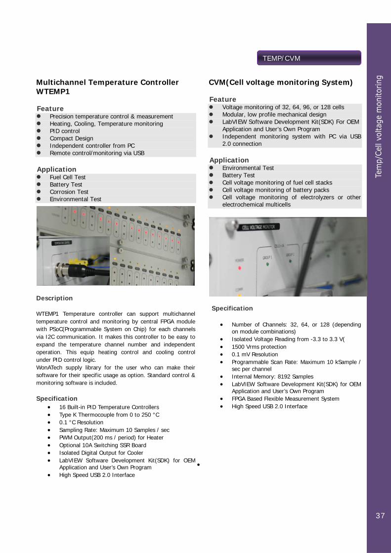
Multichannel Temperature Controller WTEMP1
Feature Precision temperature control & measurement Heating, Cooling, Temperature monitoring PID control Compact Design Independent controller from PC Remote control/monitoring via USB
Application Fuel Cell Test Battery Test Corrosion Test Environmental Test
Description WTEMP1 Temperature controller can support multichannel temperature control and monitoring by central FPGA module with PSoC(Programmable System on Chip) for each channels via I2C communication. It makes this controller to be easy to expand the temperature channel number and independent operation. This equip heating control and cooling control under PID control logic. WonATech supply library for the user who can make their software for their specific usage as option. Standard control & monitoring software is included. Specification
• 16 Built-in PID Temperature Controllers • Type K Thermocouple from 0 to 250 °C • 0.1 °C Resolution • Sampling Rate: Maximum 10 Samples / sec • PWM Output(200 ms / period) for Heater • Optional 10A Switching SSR Board • Isolated Digital Output for Cooler • LabVIEW Software Development Kit(SDK) for OEM
Application and User’s Own Program • High Speed USB 2.0 Interface
CVM(Cell voltage monitoring System)
Feature Voltage monitoring of 32, 64, 96, or 128 cells Modular, low profile mechanical design LabVIEW Software Development Kit(SDK) For OEM
Application and User’s Own Program Independent monitoring system with PC via USB
2.0 connection
Application Environmental Test Battery Test Cell voltage monitoring of fuel cell stacks Cell voltage monitoring of battery packs Cell voltage monitoring of electrolyzers or other
electrochemical multicells
Specification
• Number of Channels: 32, 64, or 128 (depending on module combinations)
• Isolated Voltage Reading from -3.3 to 3.3 V( • 1500 Vrms protection • 0.1 mV Resolution • Programmable Scan Rate: Maximum 10 kSample /
sec per channel • Internal Memory: 8192 Samples • LabVIEW Software Development Kit(SDK) for OEM
Application and User’s Own Program • FPGA Based Flexible Measurement System • High Speed USB 2.0 Interface
•
38
Z # series
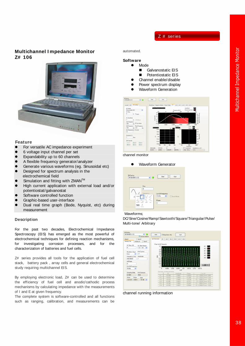
Multichannel Impedance Monitor Z# 106
Feature
For versatile AC impedance experiment 6 voltage input channel per set Expandability up to 60 channels A flexible frequency generator/analyzer Generate various waveforms (eg. Sinusoidal etc) Designed for spectrum analysis in the
electrochemical field Simulation and fitting with ZMANTM High current application with external load and/or
potentiostat/galvanostat Software controlled function Graphic-based user-interface Dual real time graph (Bode, Nyquist, etc) during
measurement Description For the past two decades, Electrochemical Impedance Spectroscopy (EIS) has emerged as the most powerful of electrochemical techniques for defining reaction mechanisms, for investigating corrosion processes, and for the characterization of batteries and fuel cells. Z# series provides all tools for the application of fuel cell stack, battery pack , array cells and general electrochemical study requiring multichannel EIS. By employing electronic load, Z# can be used to determine the efficiency of fuel cell and anodic/cathodic process mechanisms by calculating impedance with the measurements of I and E at given frequency. The complete system is software-controlled and all functions such as ranging, calibration, and measurements can be
automated. Software
Mode Galvanostatic EIS Potentiostatic EIS
Channel enable/disable Power spectrum display Waveform Generation
channel monitor
Waveform Generator
Waveforms;
DC/Sine/Cosine/Ramp/Sawtooth/Square/Triangular/Pulse/ Multi-tone/ Arbitrary
channel running information

39
Z # series
Nyquist & Bode plot for 5 channels(Real time) EIS data analysis by ZMAN software Single PC Auth copy is supplied with free of charge for Z#. (Please refer to the separate ZMAN catalogue) Library files for user software: Option User can make their own software with these libraries using LabviewTM etc. System Configuration Hardware (controller), Software, Electronic Load (option) Specification Analog Out as Signal Generator # of Channels 1 Configuration Single-ended Maximum Output -11.0 to +11.0 V (DC + AC) Voltage Offset < 0.5 mV, software corrected
zero DC Bias Range Resolution 0.0 to 5.0 V 0.076 mV 0.0 to +10.0 V 0.153 mV -5.0 to +5.0 V 0.153 mV -10 to +10.0 V 0.305 mV -2.5 to +2.5 V 0.076 mV -2.5 to +7.5 V 0.153 mV AC Waveform
Predefined Type DC, Sine, Cosine, Ramp, Sawtooth, Triangle, Square, Pulse, Multi-tone
Frequency Range
1 uHz to 100kHz Resolution: 5000 steps/decade
Frequency Accuracy
Typ. 75 ppm, Max ±200 ppm
Frequency Stability
< 2 ppm @ 1 kHz
< 20 ppm @ 10 kHz < 200 ppm @ 100 kHz < 2000 ppm(0.2%) @ 1 MHz
Amplitude 1 mVpp to 5 Vpp Post- -44 dB to +40 dB with 6 dB
Gain/Attenuation step, automatic gain selection
Reconstruction Filter
10 to 150 kHz 8th order low pass filter with 10kHz step or By-Pass
Gain Error < 0.5 % Analog In as Frequency Analyzer # of Channels Total 6, usually 1 for current
input and 5 for voltage input Maximum 60Ch in daisy chain
configuration Configuration Differential Maximum Input ±100 V Voltage Offset < 0.5 mV, software corrected
zero Bandwidth 550 kHz Input Impedance 110 kOhm Pre-Attenuation -20dB (×0.1) Post-Gain/Attenuation
-44 dB to +40 dB (×100) with 6 dB step or ×200, ×400, ×800, ×1600
Anti-aliasing Filter 10 to 150 kHz 8th order low pass filter with 10 kHz step or By-Pass
CMRR
> 80 dB @ 1 kHz, > 60 dB @ 10 kHz, > 40 dB @ 100 kHz (refer to the below graph)
100 1k 10k 100k30
40
50
60
70
80
90
100
Com
mon
Mod
e R
ejec
tion
(dB
)
Frequency (Hz)
Expansion Ports I2C In & Out Reserved for future
General Interface USB 2.0 high speed Power External 50W AC-DC Adapters,
+5/+15/-15VDC with AC Input of 100 to 240V,
2A, 50/60 Hz Operation Condition 0 to 50 °C, 0 to 90% humidity
(non-condensing) Warranty 1 year parts and labor on defects
in materials and workmanship

40
Z # series
Stack voltage EIS(1ch)
Cell voltage EIS(4ch)
Z#106 with Dynaload RBL488 series load
Stack voltage EIS(1ch)
Cell voltage EIS(4ch)
Z#106 with WonATech WEL series load Supporting external load/Potentiostat
TDI dynaload RBL488 series WonATech WLoad WonATech Potentiostats
Above models are fully PC controlled with Z#. Other model might be needed to set some parameters by manually.
Please contact with your regional distributor about other 3rd parties products’ availability with Z#. 36channels configuration (example)
For 36 channel eis measurement, 6 set of Z#106 is needed. Then you can measure eis of 36 cells or 35 cells with one total fuel cell stack(or battery pack).; One Z#106 will work as master and other 5 set of Z#106 works as slaves.
41
ZMAN
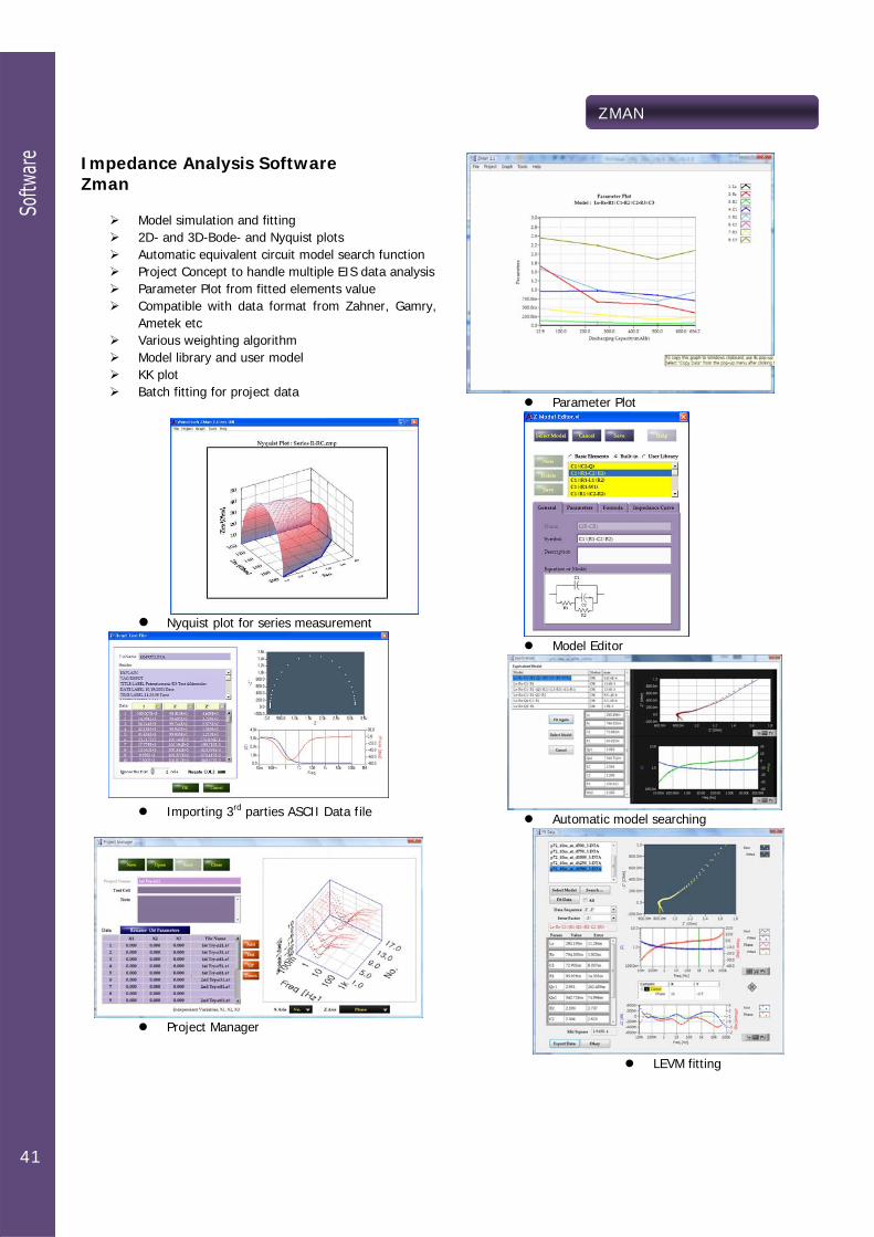
Impedance Analysis Software Zman
Model simulation and fitting 2D- and 3D-Bode- and Nyquist plots Automatic equivalent circuit model search function Project Concept to handle multiple EIS data analysis Parameter Plot from fitted elements value Compatible with data format from Zahner, Gamry,
Ametek etc Various weighting algorithm Model library and user model KK plot Batch fitting for project data
Nyquist plot for series measurement
Importing 3rd parties ASCII Data file
Project Manager
Parameter Plot
Model Editor
Automatic model searching
LEVM fitting
IVMAN
42
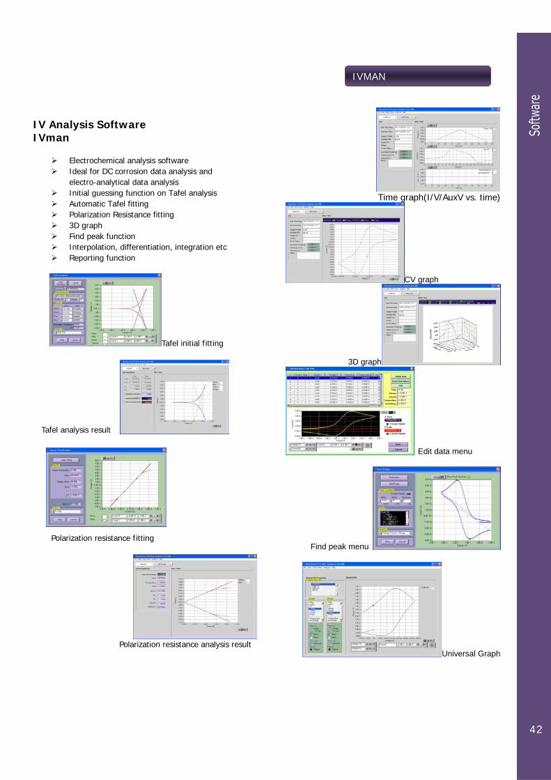
IV Analysis Software IVman
Electrochemical analysis software Ideal for DC corrosion data analysis and
electro-analytical data analysis Initial guessing function on Tafel analysis Automatic Tafel fitting Polarization Resistance fitting 3D graph Find peak function Interpolation, differentiation, integration etc Reporting function
Tafel initial fitting
Tafel analysis result
Polarization resistance fitting
Polarization resistance analysis result
Time graph(I/V/AuxV vs. time)
CV graph
3D graph
Edit data menu
Find peak menu
Universal Graph

LoadRunner
43
Dynaload control Software LoadRunner
TDI’s dynaload control software Via IEEE488 Only for model RBL488 series Virtual front panel operation Schedule file operation (batch test) Real time graphic Excel file conversion GPIB card & cable is needed
Virtual control panel
Manual operation menu
Schedule file editor for batch operation
Real time graphic during experiment
Data list
44
Ismatec Player
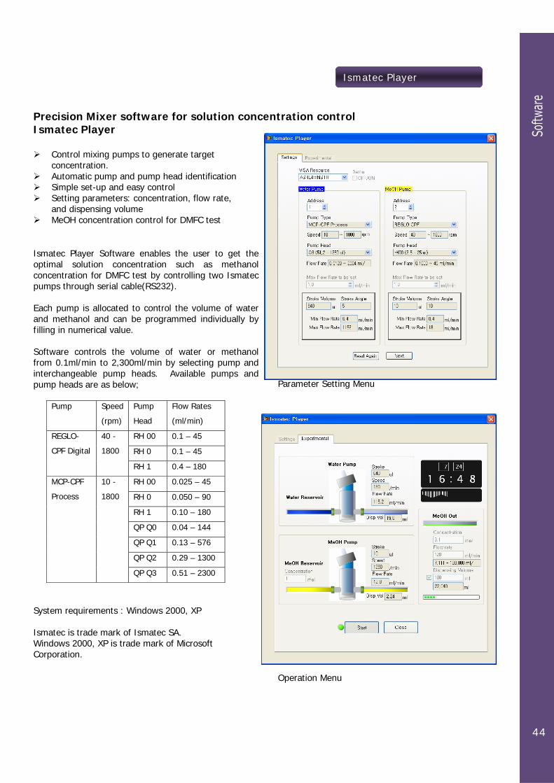
Precision Mixer software for solution concentration control Ismatec Player
Control mixing pumps to generate target concentration.
Automatic pump and pump head identification Simple set-up and easy control Setting parameters: concentration, flow rate,
and dispensing volume MeOH concentration control for DMFC test
Ismatec Player Software enables the user to get the optimal solution concentration such as methanol concentration for DMFC test by controlling two Ismatec pumps through serial cable(RS232). Each pump is allocated to control the volume of water and methanol and can be programmed individually by filling in numerical value. Software controls the volume of water or methanol from 0.1ml/min to 2,300ml/min by selecting pump and interchangeable pump heads. Available pumps and pump heads are as below;
Pump
Speed
(rpm)
Pump
Head
Flow Rates
(ml/min)
RH 00 0.1 – 45
RH 0 0.1 – 45
REGLO-
CPF Digital
40 -
1800
RH 1 0.4 – 180
RH 00 0.025 – 45
RH 0 0.050 – 90
RH 1 0.10 – 180
QP Q0 0.04 – 144
QP Q1 0.13 – 576
QP Q2 0.29 – 1300
MCP-CPF
Process
10 -
1800
QP Q3 0.51 – 2300
System requirements : Windows 2000, XP Ismatec is trade mark of Ismatec SA. Windows 2000, XP is trade mark of Microsoft Corporation.
Parameter Setting Menu
Operation Menu

Accessories
45
Universal Battery Jig UBJ8 Feature
Easy to install different size battery to the jig by pulling up the lever.
Wide contact point with gold coated contact area Coin cell is available without any attachment Individual operation is available 4 contact point(Kelvin probe type) to minimize
voltage measurement error. Front Panel attachment option is available
How to use - Set height by moving upper board - Pull up upper or lower lever - Place the battery between upper lever and lower lever - Release lever
Lithium Polymer Battery Test Jig LPBJ Feature
Easy to install lithium polymer battery to the jig by pressing pull-up lever.
Wide contact point with gold coated contact area Useful for various size of lithium polymer batteries Single or 8 ea of lithium polymer battery jig set For bundle of batteries application, cabinet type of
jig is available Structure to minimize EMI noise Safe construction for users by minimizing electrical
contact point
How to use - Pull up the lever - Place the lithium polymer battery on the bed - Release pull-up lever
Dimension 9mm (W) x 45mm (D) x 100mm (H)
Coin Cell Battery Test Jig CCBJ Easy to install different size battery into the jig by pulling up the lever. Wide contact point with gold coated contact area (4 probe contact).

Accessories
46
Fuel Cell Fixture(single cell hardware)
With rod heater
With pad heater
MEA is option Active size: 5 square centimeter, 25 square centimeter Special design by customer is available
Cell & Misc
Flat specimen holder for corrosion cell kit
Paint coating Test Cell
Water Jacketed Cell
Cell cables Faradaic cage
Dummy cell for calibration Interface cable Cell Stand

WonATech Co., Ltd. 736-1, MoonHyung-Ri, OPo-Eup, GwangJu-Si, GyeongGi-Do, 464-894, Korea Tel: +82-32-766-5974 Fax: +82-31-765-2645 e-mail: [email protected] Web site: www.xenosystem.com