Embed Size (px)
Citation preview
Page 1
GEN20552-L
Create Compelling 2D Sections, Details, and Auxiliary Views from AutoCAD 3D Models J.C. Malitzke Digital JC CAD
Description
This intermediate-to-advanced hands-on lab offers AutoCAD 3D software veterans a chance to explore the 2D model documentation of 3D models from AutoCAD 2017 software. After creating base views and projected views from 3D solid or surface models, we’ll explore sectional views. Using 3D models, we will create full, half, offset, and aligned sectional drawing views. We will create circular and rectangular detail views. We will explore editing techniques of the 3D models and update the derived drawing views. We will also explore undocumented Auxiliary View features. Export your drawing views to create 2D model space multiview drawings. If you used AutoCAD 3D software in the past to create 2D multiview drawings from 3D models, attend this class and get ready to be surprised. Your AU Expert
J. C. Malitzke is president of Digital JC CAD Services, and he is the former chair of the Computer Integrated Technologies department and a faculty member at Moraine Valley Community College in the greater Chicago area. He also managed and taught for the college’s Autodesk Authorized Training Center (ATC). He has been using and teaching products from Autodesk, Inc., since 1985. Malitzke is co-author of AutoCAD and Its Applications Advanced (Goodheart-Willcox). He is the recipient of several educator awards, including Professor of the Year, the Illinois Trustee Association's Faculty Member of the Year award, a multi ATC instructor’s award, and a Top Presenter award at Autodesk University. Malitzke is a Certified Autodesk Instructor/Professional for AutoCAD software and Inventor software. This will be his 21st year teaching or presenting at Autodesk University. He holds a BS degree in education and an MS in industrial technology from Illinois State University. Contact J.C. Malitzke at: [email protected]
Learning Objectives
Learn how to create drawing views of AutoCAD 3D models for drawing 2D sections Learn how to create drawing views of AutoCAD 3D models for drawing 2D details Learn how to edit 3D models and their 2D associated drawing views Learn how to create undocumented Auxiliary Views from AutoCAD 3D models Export drawing views to create 2D Multiview drawings in model space
Page 2
Create drawing views of AutoCAD 3D models - Drawing 2D sections Portions of this document are copyright by Goodheart-Willcox Company, Inc. and reproduced with permission from the textbook AutoCAD and its Applications--Advanced.
Drawing Views
You can create 2D drawing views from AutoCAD 3D solid or surface models using the
VIEWBASE command. This command allows you to quickly create a multiview drawing layout.
Drawing views created with the VIEWBASE command are created in paper space (layout
space). After creating a layout of views, you can dimension them using AutoCAD dimensioning
commands.
Drawing views created with the VIEWBASE command are associative. This means that
they are linked to the model from which they are created and update to reflect changes to the
model geometry. This capability allows you to keep drawing views up-to-date when design
changes are required.
When using the VIEWBASE command, you create a base view of the model and then have
the option to create additional views that are projected from the base view without exiting the
command. You can create both orthographic and isometric views. A base view created with the
VIEWBASE command is defined as a parent view. Views projected from the base view inherit
the properties of the base view, such as the drawing scale and display properties, and are
placed in orthographic alignment with the base view. If the base view is moved, any projected
views are moved with it to maintain the parent-child relationship.
Working with Drawing Views
Creating a base view creates an AutoCAD drawing view object. A drawing view has a view
border, a base grip, and a parameter grip for changing the scale. The scale and certain other
properties of the view can be edited. However, the content of the drawing view cannot be
edited.
When a base view is created, new layers are created by AutoCAD for the drawing view
geometry. The layers are created based on support for the type of geometry represented.
Object lines (visible lines) in the view are placed on a newly created layer named MD_Visible.
Hidden lines in the view are placed on a newly created layer named MD_Hidden, and so on.
The drawing view object is placed on the current layer or on the 0 layer. Additional layers may
be created by AutoCAD, depending on the type of model, display style used, and edges
Page 3
displayed in the view. However, the layers are only created to organize the drawing view
geometry. The layer properties can be modified to change the appearance of the drawing view
geometry, but the geometry cannot be otherwise modified.
Section Views
A section view shows the internal features of an object along a section line (cutting plane).
A section view is projected from an existing view, such as an orthographic top view. The existing
view serves as a parent view. To create a section view, you pick points on the parent view to
define the section line (cutting-plane line). You can also select an object, such as a line or
polyline, to define the section line. Section views are created using the VIEWSECTION
command. This command can be used to create full, half, offset, or aligned sections from an
AutoCAD 3D model or an Autodesk Inventor model.
Section views created with the VIEWSECTION command are created in the same paper
space layout as other drawing views. Section views are associative. A section view is linked to
the parent view that creates the section view. As with other types of drawing views, section
views are updated automatically when model changes are made if the VIEWUPDATEAUTO
system variable is set to 1.
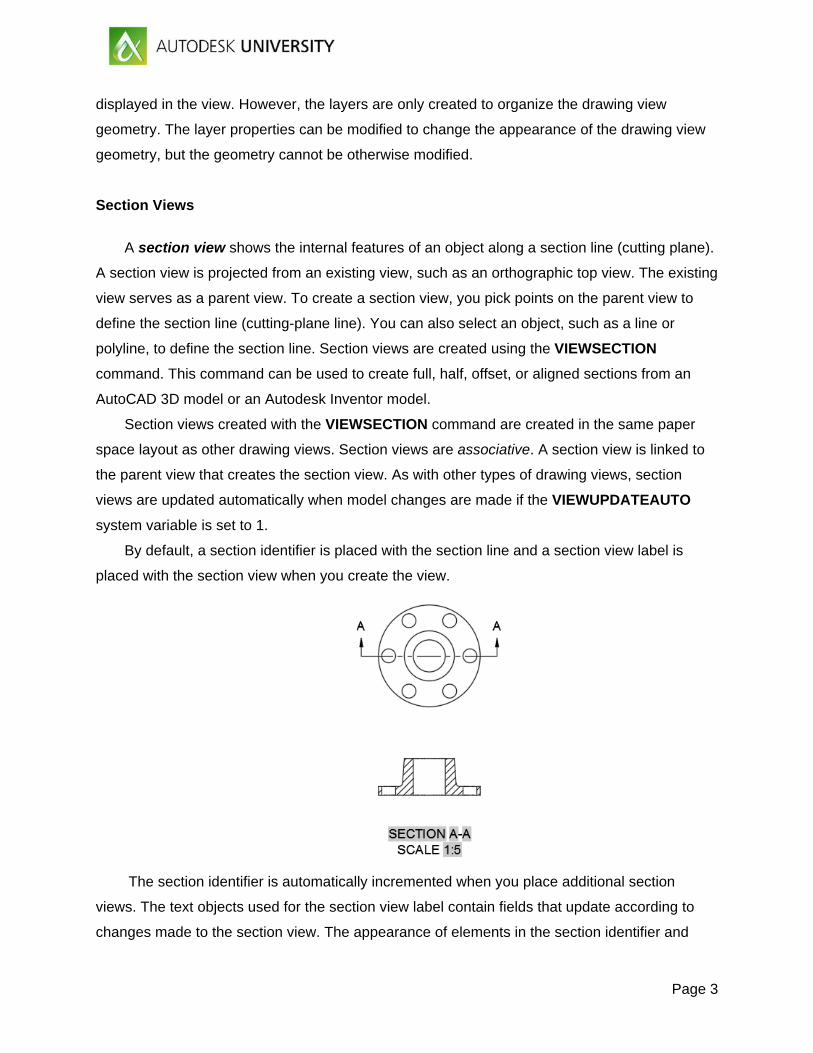
By default, a section identifier is placed with the section line and a section view label is
placed with the section view when you create the view.
The section identifier is automatically incremented when you place additional section
views. The text objects used for the section view label contain fields that update according to
changes made to the section view. The appearance of elements in the section identifier and
Page 4
section view label is controlled by the section view style. A section view style defines settings
such as the text style and height, direction arrow size and length, and hatch pattern used for
sectioning. A section view style is similar to a dimension style and includes similar controls.
VIEWSECTIONSTYLE
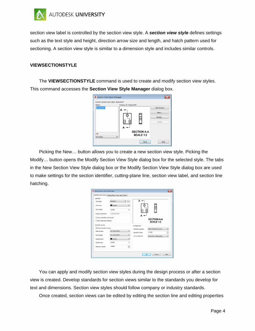
The VIEWSECTIONSTYLE command is used to create and modify section view styles.
This command accesses the Section View Style Manager dialog box.
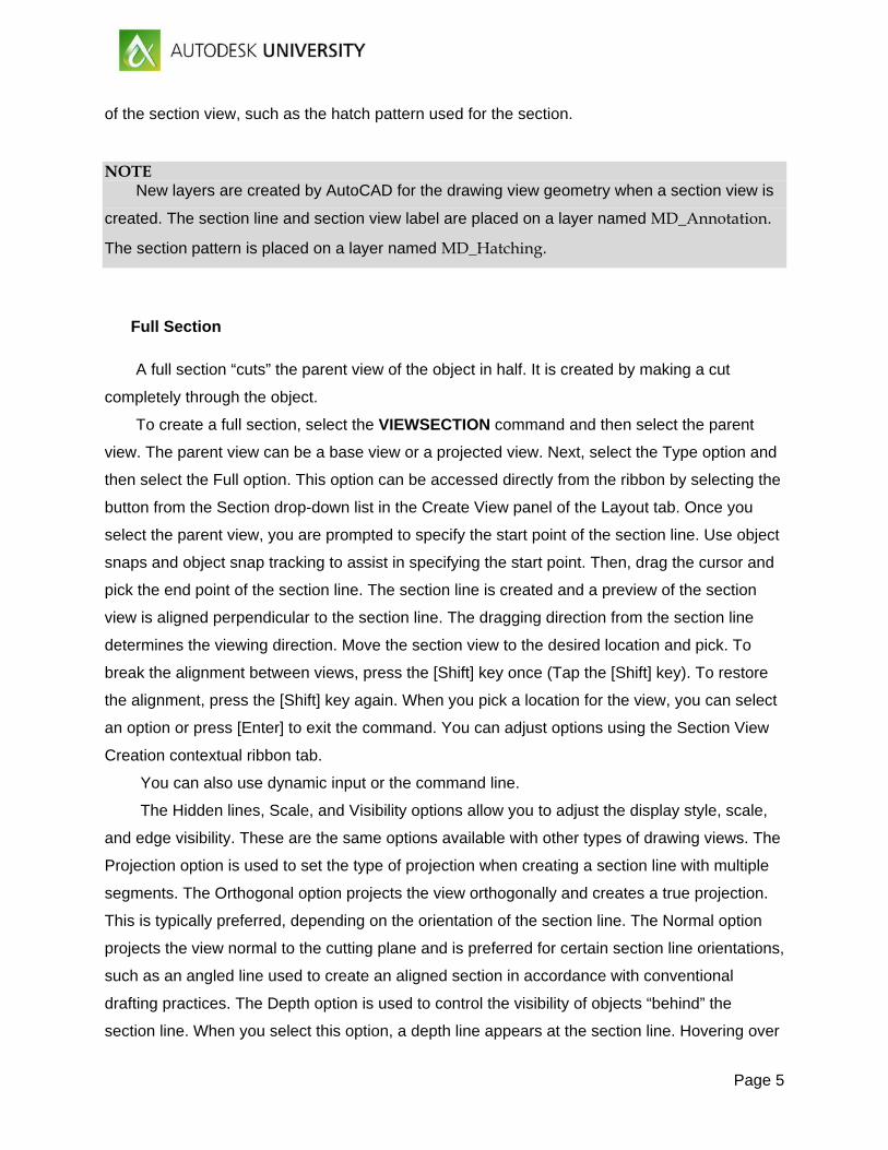
Picking the New… button allows you to create a new section view style. Picking the
Modify… button opens the Modify Section View Style dialog box for the selected style. The tabs
in the New Section View Style dialog box or the Modify Section View Style dialog box are used
to make settings for the section identifier, cutting-plane line, section view label, and section line
hatching.
You can apply and modify section view styles during the design process or after a section
view is created. Develop standards for section views similar to the standards you develop for
text and dimensions. Section view styles should follow company or industry standards.
Once created, section views can be edited by editing the section line and editing properties
Page 5
of the section view, such as the hatch pattern used for the section.
NOTE New layers are created by AutoCAD for the drawing view geometry when a section view is
created. The section line and section view label are placed on a layer named MD_Annotation.
The section pattern is placed on a layer named MD_Hatching.
Full Section
A full section “cuts” the parent view of the object in half. It is created by making a cut
completely through the object.
To create a full section, select the VIEWSECTION command and then select the parent
view. The parent view can be a base view or a projected view. Next, select the Type option and
then select the Full option. This option can be accessed directly from the ribbon by selecting the
button from the Section drop-down list in the Create View panel of the Layout tab. Once you
select the parent view, you are prompted to specify the start point of the section line. Use object
snaps and object snap tracking to assist in specifying the start point. Then, drag the cursor and
pick the end point of the section line. The section line is created and a preview of the section
view is aligned perpendicular to the section line. The dragging direction from the section line
determines the viewing direction. Move the section view to the desired location and pick. To
break the alignment between views, press the [Shift] key once (Tap the [Shift] key). To restore
the alignment, press the [Shift] key again. When you pick a location for the view, you can select
an option or press [Enter] to exit the command. You can adjust options using the Section View
Creation contextual ribbon tab.
You can also use dynamic input or the command line.
The Hidden lines, Scale, and Visibility options allow you to adjust the display style, scale,
and edge visibility. These are the same options available with other types of drawing views. The
Projection option is used to set the type of projection when creating a section line with multiple
segments. The Orthogonal option projects the view orthogonally and creates a true projection.
This is typically preferred, depending on the orientation of the section line. The Normal option
projects the view normal to the cutting plane and is preferred for certain section line orientations,
such as an angled line used to create an aligned section in accordance with conventional
drafting practices. The Depth option is used to control the visibility of objects “behind” the
section line. When you select this option, a depth line appears at the section line. Hovering over
Page 6
this line and dragging allows you to set the depth of the section view. Objects that are behind
the depth line will not be visible in the section view. Selecting the default Full option includes all
objects within the section view. Selecting the Slice option removes all objects behind the section
line, creating a thin representation section view. The Slice option may be practical for special
section view documentations.
The Annotation option allows you to enter the text used for the section identifier and specify
whether a view label is shown. As previously discussed, the section identifier is automatically
incremented when creating additional section views. The Hatch option is used to specify
whether a hatch pattern is used for the section view. The Move option allows you to adjust the
location of the view after selecting the initial position. When using this option, you can press the
[Shift] key to break the alignment between views.
NOTE After placing the section view, you can use grips to edit the section line and the section
identifier. Editing the position of the section line alters the section view. To access grip editing
options for a section line, hover over a vertex grip. This displays a shortcut menu with options
similar to those for editing a polyline. You can stretch the vertex, add a vertex, add a segment,
and flip the viewing direction. Hovering over one of the section identifier grips allows you to
move the identifier with or without the section line and reset the identifier to the initial position.
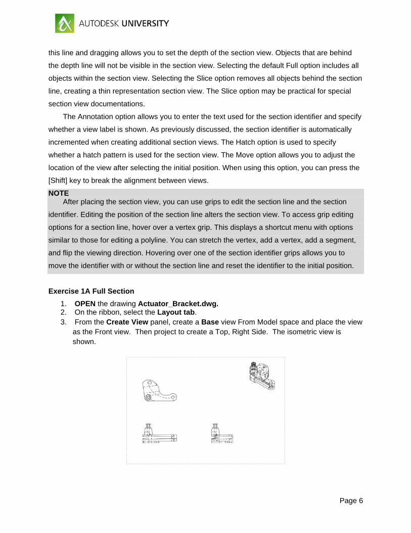
Exercise 1A Full Section
1. OPEN the drawing Actuator_Bracket.dwg. 2. On the ribbon, select the Layout tab. 3. From the Create View panel, create a Base view From Model space and place the view
as the Front view. Then project to create a Top, Right Side. The isometric view is shown.
Page 7
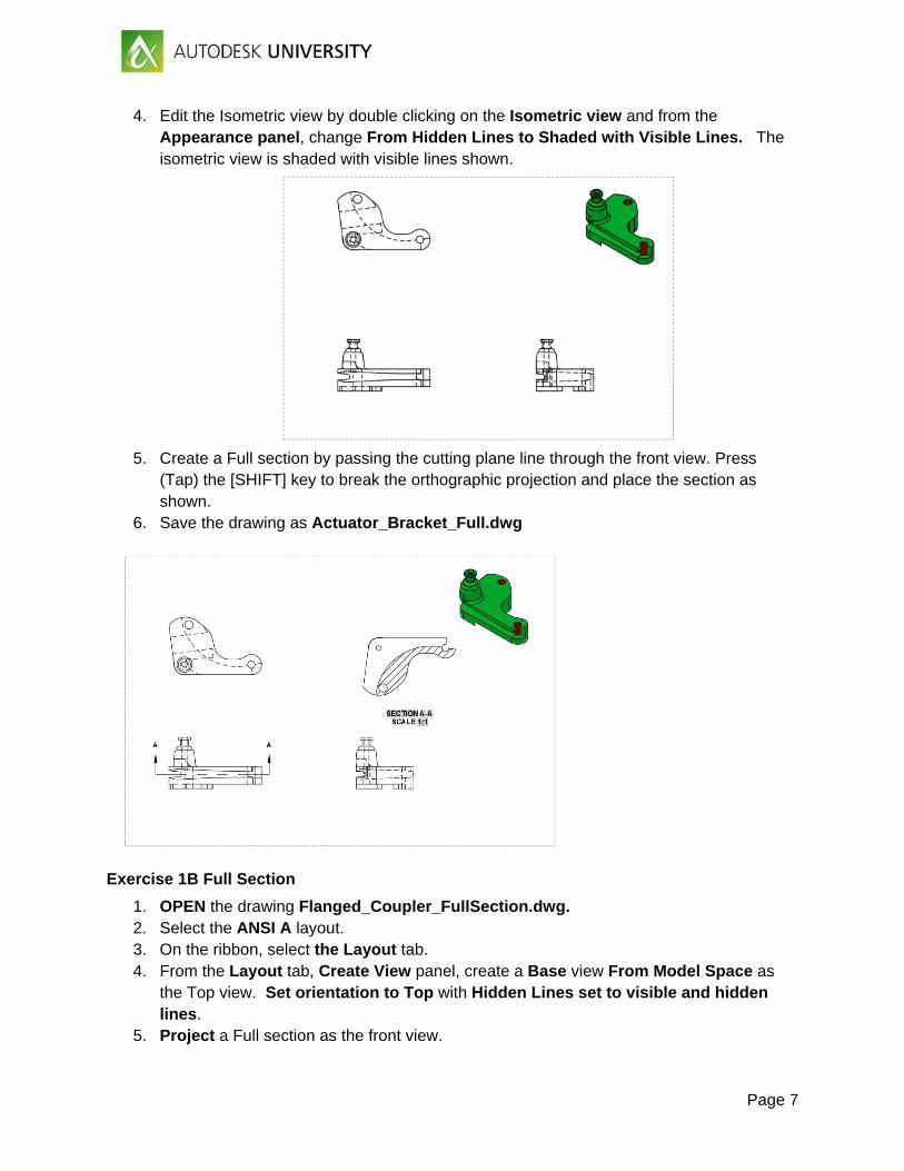
4. Edit the Isometric view by double clicking on the Isometric view and from the Appearance panel, change From Hidden Lines to Shaded with Visible Lines. The isometric view is shaded with visible lines shown.
5. Create a Full section by passing the cutting plane line through the front view. Press
(Tap) the [SHIFT] key to break the orthographic projection and place the section as shown.
6. Save the drawing as Actuator_Bracket_Full.dwg
Exercise 1B Full Section
1. OPEN the drawing Flanged_Coupler_FullSection.dwg. 2. Select the ANSI A layout. 3. On the ribbon, select the Layout tab. 4. From the Layout tab, Create View panel, create a Base view From Model Space as
the Top view. Set orientation to Top with Hidden Lines set to visible and hidden lines.
5. Project a Full section as the front view.
Page 8
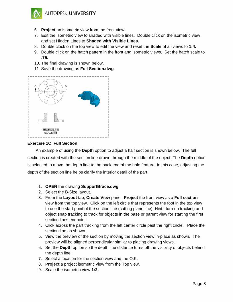
6. Project an isometric view from the front view. 7. Edit the isometric view to shaded with visible lines. Double click on the isometric view
and set Hidden Lines to Shaded with Visible Lines. 8. Double clock on the top view to edit the view and reset the Scale of all views to 1:4. 9. Double click on the hatch pattern in the front and isometric views. Set the hatch scale to
.75. 10. The final drawing is shown below. 11. Save the drawing as Full Section.dwg
Exercise 1C Full Section
An example of using the Depth option to adjust a half section is shown below. The full
section is created with the section line drawn through the middle of the object. The Depth option
is selected to move the depth line to the back end of the hole feature. In this case, adjusting the
depth of the section line helps clarify the interior detail of the part.
1. OPEN the drawing SupportBrace.dwg. 2. Select the B-Size layout. 3. From the Layout tab, Create View panel, Project the front view as a Full section
view from the top view. Click on the left circle that represents the foot in the top view to use the start point of the section line (cutting plane line). Hint: turn on tracking and object snap tracking to track for objects in the base or parent view for starting the first section lines endpoint.
4. Click across the part tracking from the left center circle past the right circle. Place the section line as shown.
5. View the preview of the section by moving the section view in-place as shown. The preview will be aligned perpendicular similar to placing drawing views.
6. Set the Depth option so the depth line distance turns off the visibility of objects behind the depth line.
7. Select a location for the section view and the O.K. 8. Project a project isometric view from the Top view. 9. Scale the isometric view 1:2.
Page 9
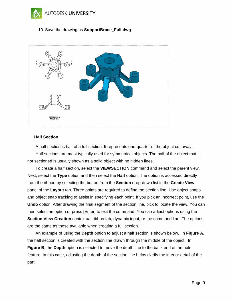
10. Save the drawing as SupportBrace_Full.dwg
Half Section A half section is half of a full section. It represents one-quarter of the object cut away.
Half sections are most typically used for symmetrical objects. The half of the object that is
not sectioned is usually shown as a solid object with no hidden lines.
To create a half section, select the VIEWSECTION command and select the parent view.
Next, select the Type option and then select the Half option. The option is accessed directly
from the ribbon by selecting the button from the Section drop-down list in the Create View
panel of the Layout tab. Three points are required to define the section line. Use object snaps
and object snap tracking to assist in specifying each point. If you pick an incorrect point, use the
Undo option. After drawing the final segment of the section line, pick to locate the view. You can
then select an option or press [Enter] to exit the command. You can adjust options using the
Section View Creation contextual ribbon tab, dynamic input, or the command line. The options
are the same as those available when creating a full section.
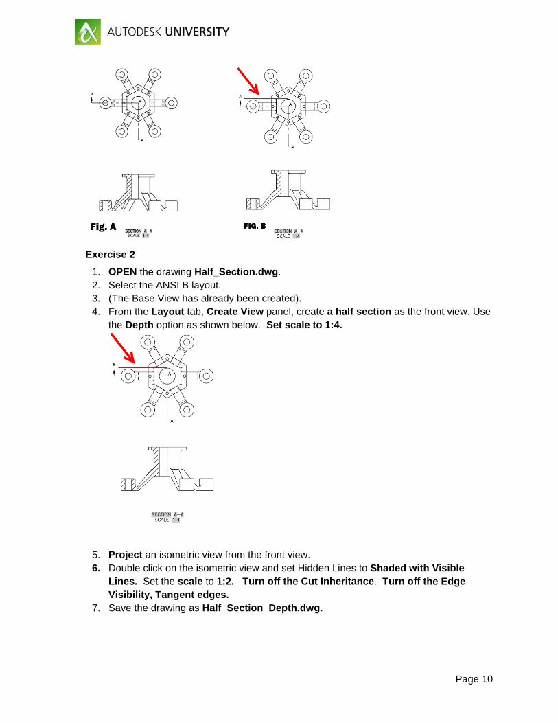
An example of using the Depth option to adjust a half section is shown below. In Figure A,
the half section is created with the section line drawn through the middle of the object. In
Figure B, the Depth option is selected to move the depth line to the back end of the hole
feature. In this case, adjusting the depth of the section line helps clarify the interior detail of the
part.
Page 10
Exercise 2
1. OPEN the drawing Half_Section.dwg. 2. Select the ANSI B layout. 3. (The Base View has already been created). 4. From the Layout tab, Create View panel, create a half section as the front view. Use
the Depth option as shown below. Set scale to 1:4.
5. Project an isometric view from the front view. 6. Double click on the isometric view and set Hidden Lines to Shaded with Visible
Lines. Set the scale to 1:2. Turn off the Cut Inheritance. Turn off the Edge Visibility, Tangent edges.
7. Save the drawing as Half_Section_Depth.dwg.
Page 11
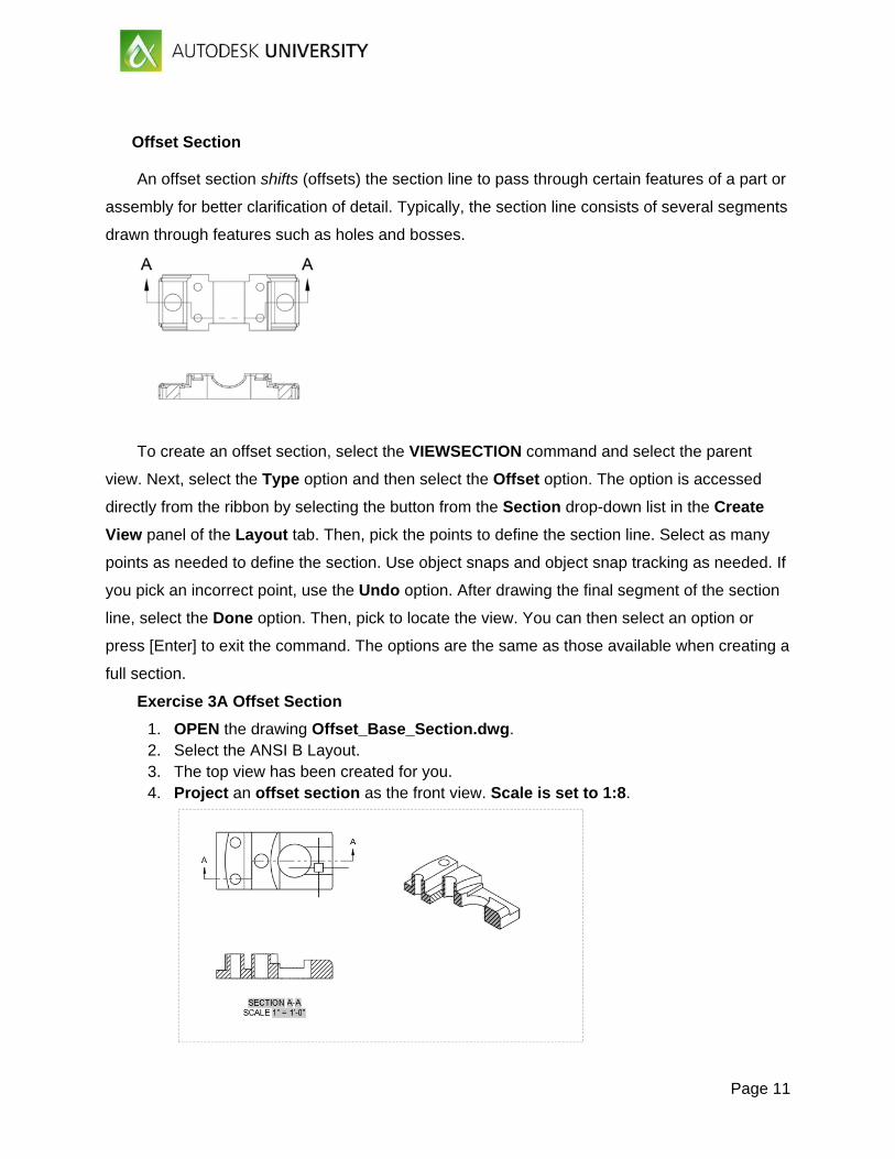
Offset Section An offset section shifts (offsets) the section line to pass through certain features of a part or
assembly for better clarification of detail. Typically, the section line consists of several segments
drawn through features such as holes and bosses.
To create an offset section, select the VIEWSECTION command and select the parent
view. Next, select the Type option and then select the Offset option. The option is accessed
directly from the ribbon by selecting the button from the Section drop-down list in the Create
View panel of the Layout tab. Then, pick the points to define the section line. Select as many
points as needed to define the section. Use object snaps and object snap tracking as needed. If
you pick an incorrect point, use the Undo option. After drawing the final segment of the section
line, select the Done option. Then, pick to locate the view. You can then select an option or
press [Enter] to exit the command. The options are the same as those available when creating a
full section.
Exercise 3A Offset Section
1. OPEN the drawing Offset_Base_Section.dwg. 2. Select the ANSI B Layout. 3. The top view has been created for you. 4. Project an offset section as the front view. Scale is set to 1:8.
Page 12
5. Project from the front view as an isometric section view. 6. Change the isometric view to Shaded with Visible lines. 7. Edit the isometric view by using Cut Inheritance. Set cUt to No. What happens to
the isometric view? 8. Save the drawing as Offset_Section.dwg.
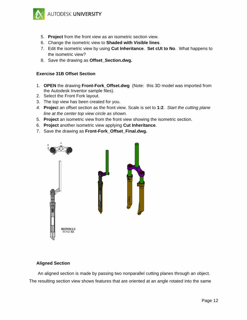
Exercise 31B Offset Section
1. OPEN the drawing Front-Fork_Offset.dwg (Note: this 3D model was imported from
the Autodesk Inventor sample files). 2. Select the Front Fork layout. 3. The top view has been created for you. 4. Project an offset section as the front view. Scale is set to 1:2. Start the cutting plane
line at the center top view circle as shown. 5. Project an isometric view from the front view showing the isometric section. 6. Project another isometric view applying Cut Inheritance. 7. Save the drawing as Front-Fork_Offset_Final.dwg.
Aligned Section An aligned section is made by passing two nonparallel cutting planes through an object.
The resulting section view shows features that are oriented at an angle rotated into the same
Page 13
cutting plane.
The purpose of an aligned section is to show the true size and shape of a feature. In Figure
14-17A, an aligned section is created to show the true size and shape of the right arm. Notice
that the right arm is rotated into the center cutting plane to project the view. For this view, the
Projection option is set to Normal. This is conventional practice.
To create an aligned section, select the VIEWSECTION command, select the parent view,
and access the Aligned option. The option is accessed directly from the ribbon by selecting the
Aligned option from the Section drop-down list in the Create View panel of the Layout tab.
Then, pick the points to define the section line. Use object snaps and object snap tracking as
needed. After drawing the final segment of the section line, select the Done option. Then, pick
to locate the view. You can then select an option or press [Enter] to exit the command. The
options are the same as those available when creating a full section.
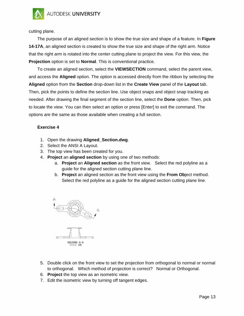
Exercise 4
1. Open the drawing Aligned_Section.dwg. 2. Select the ANSI A Layout. 3. The top view has been created for you. 4. Project an aligned section by using one of two methods:
a. Project an Aligned section as the front view. Select the red polyline as a guide for the aligned section cutting plane line.
b. Project an aligned section as the front view using the From Object method. Select the red polyline as a guide for the aligned section cutting plane line.
5. Double click on the front view to set the projection from orthogonal to normal or normal to orthogonal. Which method of projection is correct? Normal or Orthogonal.
6. Project the top view as an isometric view. 7. Edit the isometric view by turning off tangent edges.
Page 14
8. Edit the isometric view by changes the appearance to shaded with visible lines. 9. Erase the red polyline. 10. Save the drawing as Aligned.dwg.
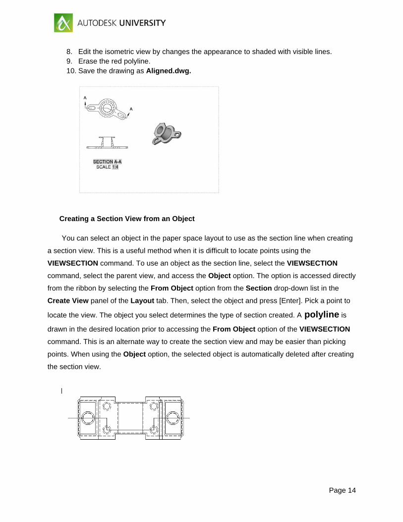
Creating a Section View from an Object
You can select an object in the paper space layout to use as the section line when creating
a section view. This is a useful method when it is difficult to locate points using the
VIEWSECTION command. To use an object as the section line, select the VIEWSECTION
command, select the parent view, and access the Object option. The option is accessed directly
from the ribbon by selecting the From Object option from the Section drop-down list in the
Create View panel of the Layout tab. Then, select the object and press [Enter]. Pick a point to
locate the view. The object you select determines the type of section created. A polyline is
drawn in the desired location prior to accessing the From Object option of the VIEWSECTION
command. This is an alternate way to create the section view and may be easier than picking
points. When using the Object option, the selected object is automatically deleted after creating
the section view.
Page 15
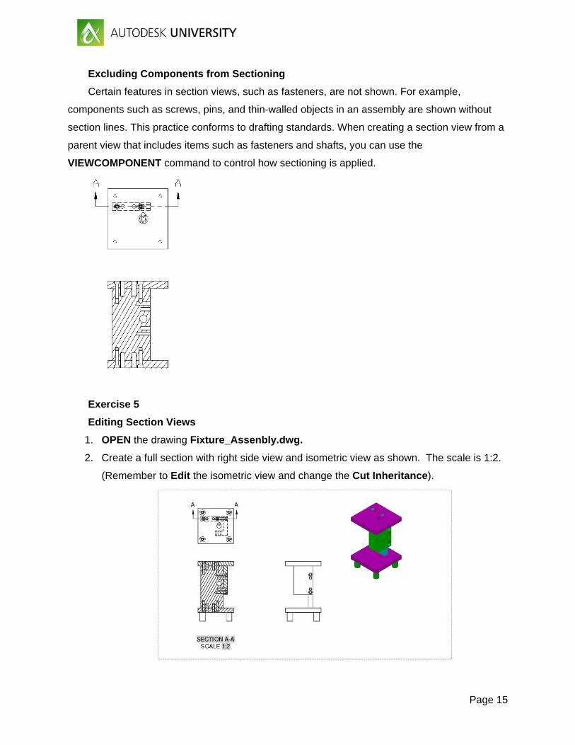
Excluding Components from Sectioning
Certain features in section views, such as fasteners, are not shown. For example,
components such as screws, pins, and thin-walled objects in an assembly are shown without
section lines. This practice conforms to drafting standards. When creating a section view from a
parent view that includes items such as fasteners and shafts, you can use the
VIEWCOMPONENT command to control how sectioning is applied.
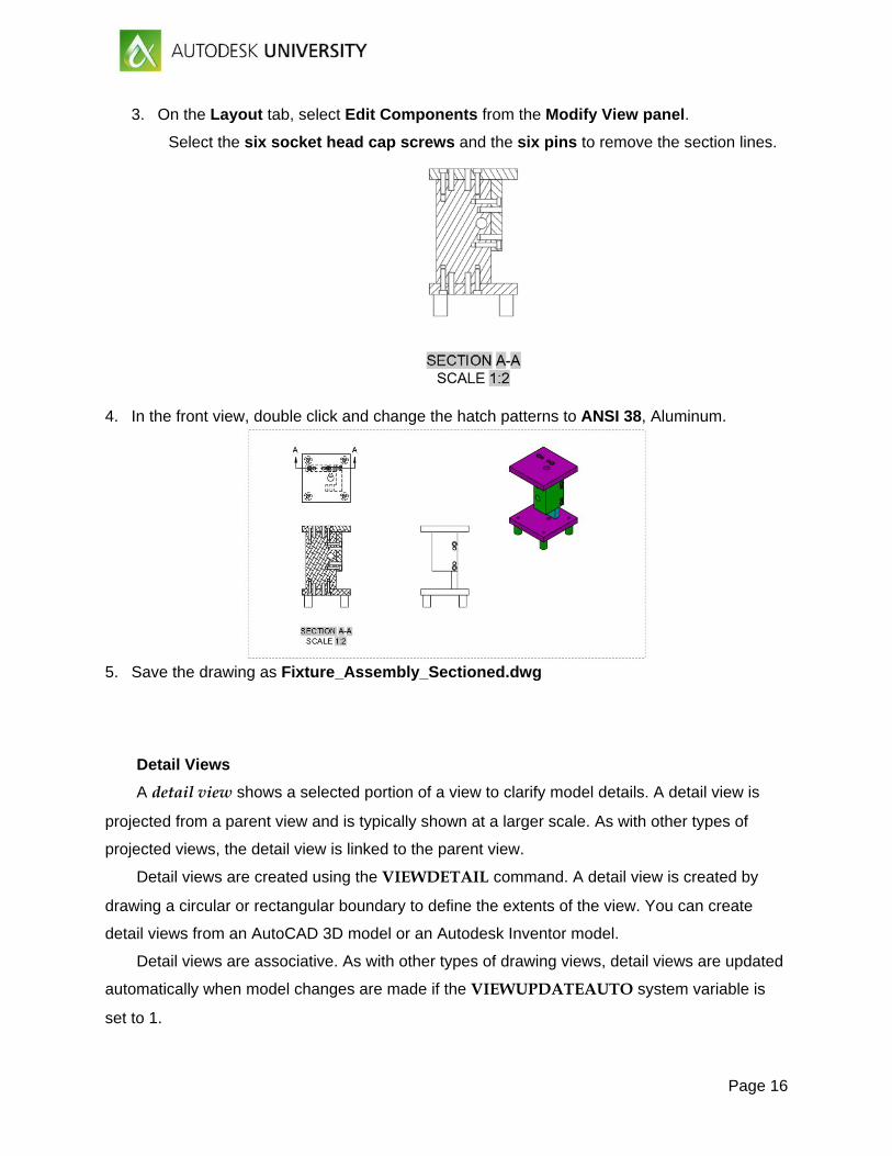
Exercise 5
Editing Section Views
1. OPEN the drawing Fixture_Assenbly.dwg.
2. Create a full section with right side view and isometric view as shown. The scale is 1:2.
(Remember to Edit the isometric view and change the Cut Inheritance).
Page 16
3. On the Layout tab, select Edit Components from the Modify View panel.
Select the six socket head cap screws and the six pins to remove the section lines.
4. In the front view, double click and change the hatch patterns to ANSI 38, Aluminum.
5. Save the drawing as Fixture_Assembly_Sectioned.dwg
Detail Views
A detail view shows a selected portion of a view to clarify model details. A detail view is
projected from a parent view and is typically shown at a larger scale. As with other types of
projected views, the detail view is linked to the parent view.
Detail views are created using the VIEWDETAIL command. A detail view is created by
drawing a circular or rectangular boundary to define the extents of the view. You can create
detail views from an AutoCAD 3D model or an Autodesk Inventor model.
Detail views are associative. As with other types of drawing views, detail views are updated
automatically when model changes are made if the VIEWUPDATEAUTO system variable is
set to 1.
Page 17
Creating a detail view places a detail boundary representing the “cutout” area in the parent
view. The detail boundary includes a detail identifier. The detail view is placed in another
location on the drawing and includes a view label. The detail identification is automatically
incremented when you place additional detail views. The appearance of elements in the detail
identifier and detail view label is controlled by the detail view style. A detail view style defines
settings such as the text style and height, symbol size, and detail boundary appearance.
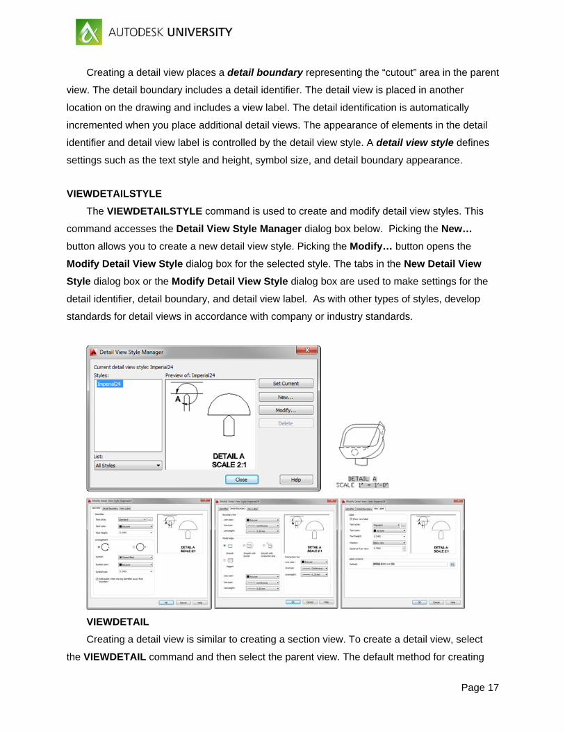
VIEWDETAILSTYLE
The VIEWDETAILSTYLE command is used to create and modify detail view styles. This
command accesses the Detail View Style Manager dialog box below. Picking the New…
button allows you to create a new detail view style. Picking the Modify… button opens the
Modify Detail View Style dialog box for the selected style. The tabs in the New Detail View
Style dialog box or the Modify Detail View Style dialog box are used to make settings for the
detail identifier, detail boundary, and detail view label. As with other types of styles, develop
standards for detail views in accordance with company or industry standards.
VIEWDETAIL
Creating a detail view is similar to creating a section view. To create a detail view, select
the VIEWDETAIL command and then select the parent view. The default method for creating
Page 18
the view is to create a circular detail boundary. This is the preferred display for most detail
views. You can change the boundary type to rectangular using the Boundary option. With the
Rectangular option, a rectangular detail boundary is drawn and the detail view has a
rectangular outline.
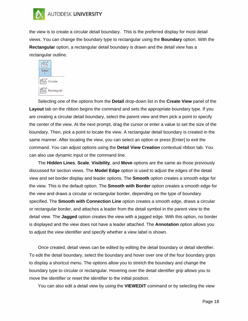
Selecting one of the options from the Detail drop-down list in the Create View panel of the
Layout tab on the ribbon begins the command and sets the appropriate boundary type. If you
are creating a circular detail boundary, select the parent view and then pick a point to specify
the center of the view. At the next prompt, drag the cursor or enter a value to set the size of the
boundary. Then, pick a point to locate the view. A rectangular detail boundary is created in the
same manner. After locating the view, you can select an option or press [Enter] to exit the
command. You can adjust options using the Detail View Creation contextual ribbon tab. You
can also use dynamic input or the command line.
The Hidden Lines, Scale, Visibility, and Move options are the same as those previously
discussed for section views. The Model Edge option is used to adjust the edges of the detail
view and set border display and leader options. The Smooth option creates a smooth edge for
the view. This is the default option. The Smooth with Border option creates a smooth edge for
the view and draws a circular or rectangular border, depending on the type of boundary
specified. The Smooth with Connection Line option creates a smooth edge, draws a circular
or rectangular border, and attaches a leader from the detail symbol in the parent view to the
detail view. The Jagged option creates the view with a jagged edge. With this option, no border
is displayed and the view does not have a leader attached. The Annotation option allows you
to adjust the view identifier and specify whether a view label is shown.
Once created, detail views can be edited by editing the detail boundary or detail identifier.
To edit the detail boundary, select the boundary and hover over one of the four boundary grips
to display a shortcut menu. The options allow you to stretch the boundary and change the
boundary type to circular or rectangular. Hovering over the detail identifier grip allows you to
move the identifier or reset the identifier to the initial position.
You can also edit a detail view by using the VIEWEDIT command or by selecting the view
Page 19
to display grips. A detail view has a base grip providing access to the standard grip editing
options and a parameter grip for changing the scale. The detail view label is an mtext object. It
can be moved by selecting the label and then selecting the base grip.
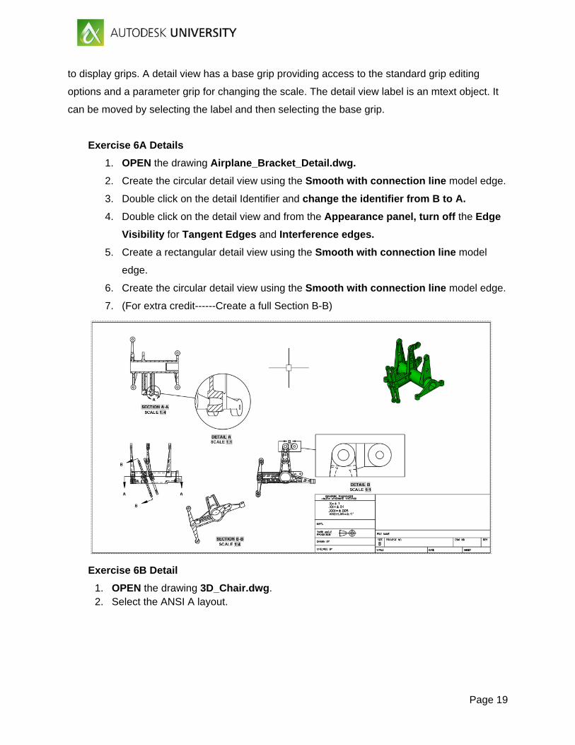
Exercise 6A Details
1. OPEN the drawing Airplane_Bracket_Detail.dwg.
2. Create the circular detail view using the Smooth with connection line model edge.
3. Double click on the detail Identifier and change the identifier from B to A.
4. Double click on the detail view and from the Appearance panel, turn off the Edge
Visibility for Tangent Edges and Interference edges.
5. Create a rectangular detail view using the Smooth with connection line model
edge.
6. Create the circular detail view using the Smooth with connection line model edge.
7. (For extra credit------Create a full Section B-B)
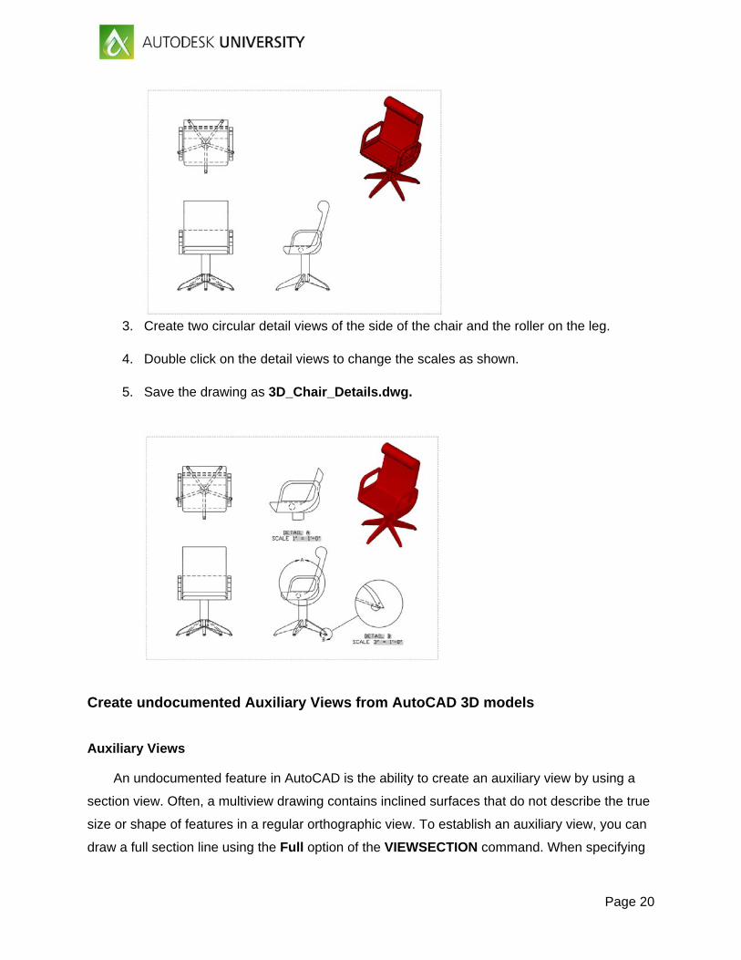
Exercise 6B Detail
1. OPEN the drawing 3D_Chair.dwg. 2. Select the ANSI A layout.
Page 20
3. Create two circular detail views of the side of the chair and the roller on the leg.
4. Double click on the detail views to change the scales as shown.
5. Save the drawing as 3D_Chair_Details.dwg.
Create undocumented Auxiliary Views from AutoCAD 3D models
Auxiliary Views
An undocumented feature in AutoCAD is the ability to create an auxiliary view by using a
section view. Often, a multiview drawing contains inclined surfaces that do not describe the true
size or shape of features in a regular orthographic view. To establish an auxiliary view, you can
draw a full section line using the Full option of the VIEWSECTION command. When specifying
Page 21
the section line, pick two points on the inclined surface. If needed, draw a parallel construction
line across the inclined surface and use it to create the section line. The auxiliary view plane is
oriented parallel to the inclined edge of the surface and the view is created perpendicular to the
surface. To remove the display of the section line and view label from the drawing, freeze the
MD_Annotation layer. Notice that since the section line does not intersect the object, no hatch
pattern is created.
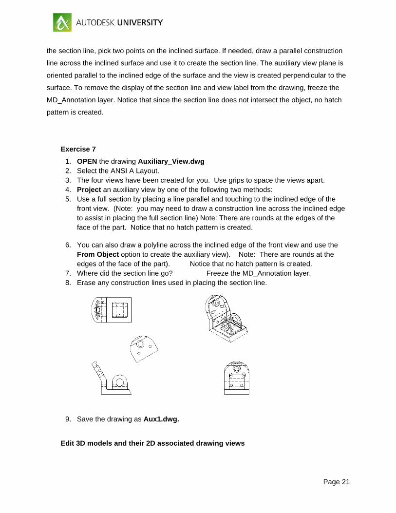
Exercise 7
1. OPEN the drawing Auxiliary_View.dwg 2. Select the ANSI A Layout. 3. The four views have been created for you. Use grips to space the views apart. 4. Project an auxiliary view by one of the following two methods: 5. Use a full section by placing a line parallel and touching to the inclined edge of the
front view. (Note: you may need to draw a construction line across the inclined edge to assist in placing the full section line) Note: There are rounds at the edges of the face of the part. Notice that no hatch pattern is created.
6. You can also draw a polyline across the inclined edge of the front view and use the From Object option to create the auxiliary view). Note: There are rounds at the edges of the face of the part). Notice that no hatch pattern is created.
7. Where did the section line go? Freeze the MD_Annotation layer. 8. Erase any construction lines used in placing the section line.
9. Save the drawing as Aux1.dwg.
Edit 3D models and their 2D associated drawing views
Page 22
Editing Drawing Views
Drawing views can be edited after being created. Like other AutoCAD objects, drawing
views can be moved or rotated. In addition, certain properties of drawing views, such as the
display style, edge visibility, and scale, can be modified.
VIEWEDIT
The VIEWEDIT command can be used to edit the properties of a drawing view. You can
quickly initiate this command by double-clicking on a view. The Drawing View Editor contextual
ribbon tab appears. The editing options are similar to the options available when you create a
base view.
As previously discussed, projected views inherit the properties of the base view when
created. If you select a projected view with the VIEWEDIT command, you can change the
display style, edge visibility, and scale.
A quick way to change the scale of a view is to use the scale parameter grip. This grip
appears when you single-click on a view. Pick on the grip to access a different scale. To move a
drawing view, single-click on the view and then pick on the base grip to move the view directly.
When moving a parent view, any child views will move accordingly to maintain alignment. When
moving a child view, you can move the view, but it cannot be moved out of alignment with the
parent view. This applies to orthogonal views. If you move an isometric view, it is not aligned to
other views and can be moved freely around the layout.
Picking on a drawing view grip and right-clicking displays a shortcut menu. The Stretch
option can be used to move the drawing view. The Rotate option can be used to rotate the
drawing view. You can rotate the view dynamically using the cursor or you can specify a rotation
angle. If a drawing view is rotated, any parent-child relationships that exist between the view
and other drawing views are broken.
You can break the alignment between parent and child views when moving a child view.
To do this, select the drawing view grip and press [Shift] (tap the Shift key) once. The view is
free to move to a different location. To reestablish the alignment, press [Shift] again. The
alignment is restored and the child view cannot move out of alignment with the parent view.
If a view is already placed, you can break the alignment by selecting the view pressing
(tapping) the SHIFT Key.
Page 23
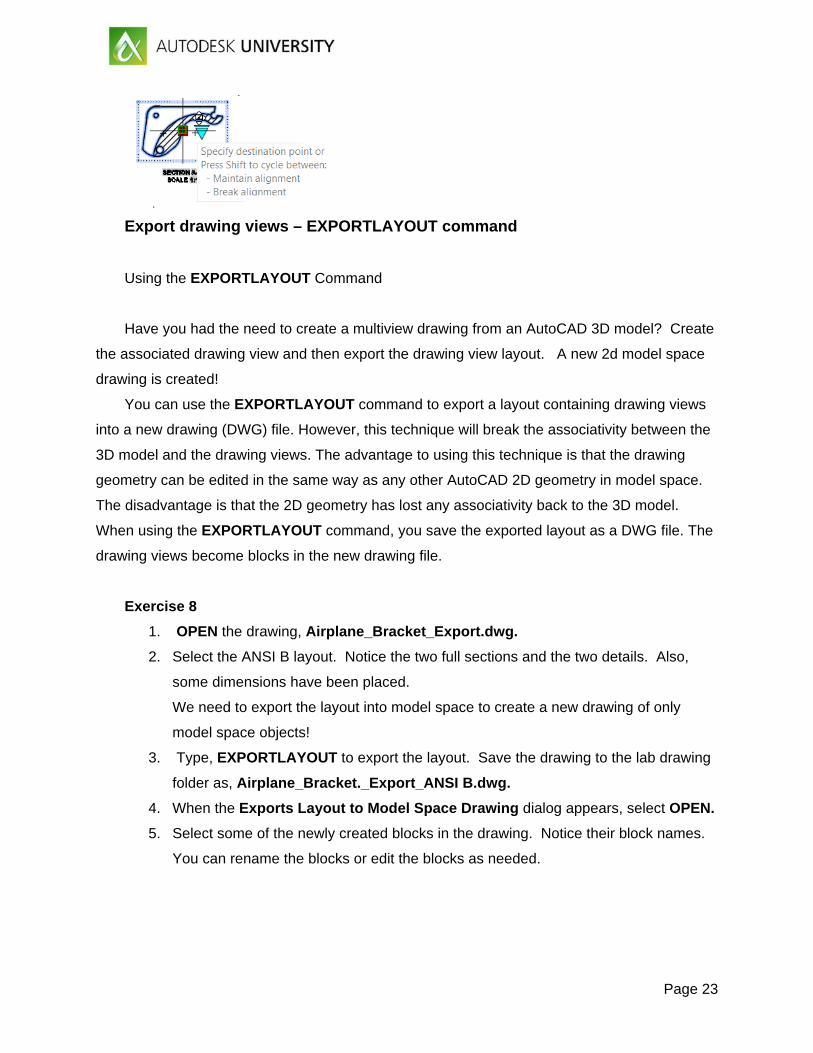
Export drawing views – EXPORTLAYOUT command
Using the EXPORTLAYOUT Command
Have you had the need to create a multiview drawing from an AutoCAD 3D model? Create
the associated drawing view and then export the drawing view layout. A new 2d model space
drawing is created!
You can use the EXPORTLAYOUT command to export a layout containing drawing views
into a new drawing (DWG) file. However, this technique will break the associativity between the
3D model and the drawing views. The advantage to using this technique is that the drawing
geometry can be edited in the same way as any other AutoCAD 2D geometry in model space.
The disadvantage is that the 2D geometry has lost any associativity back to the 3D model.
When using the EXPORTLAYOUT command, you save the exported layout as a DWG file. The
drawing views become blocks in the new drawing file.
Exercise 8
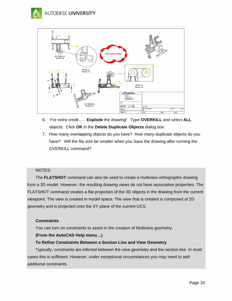
1. OPEN the drawing, Airplane_Bracket_Export.dwg.
2. Select the ANSI B layout. Notice the two full sections and the two details. Also,
some dimensions have been placed.
We need to export the layout into model space to create a new drawing of only
model space objects!
3. Type, EXPORTLAYOUT to export the layout. Save the drawing to the lab drawing
folder as, Airplane_Bracket._Export_ANSI B.dwg.
4. When the Exports Layout to Model Space Drawing dialog appears, select OPEN.
5. Select some of the newly created blocks in the drawing. Notice their block names.
You can rename the blocks or edit the blocks as needed.
Page 24
6. For extra credit……Explode the drawing! Type OVERKILL and select ALL
objects. Click OK in the Delete Duplicate Objects dialog box.
7. How many overlapping objects do you have? How many duplicate objects do you
have? Will the file size be smaller when you Save the drawing after running the
OVERKILL command?
NOTES:
The FLATSHOT command can also be used to create a multiview orthographic drawing
from a 3D model. However, the resulting drawing views do not have associative properties. The
FLATSHOT command creates a flat projection of the 3D objects in the drawing from the current
viewpoint. The view is created in model space. The view that is created is composed of 2D
geometry and is projected onto the XY plane of the current UCS.
Constraints
You can turn on constraints to assist in the creation of Multiview geometry.
(From the AutoCAD Help menu…)
To Refine Constraints Between a Section Line and View Geometry
Typically, constraints are inferred between the view geometry and the section line. In most
cases this is sufficient. However, under exceptional circumstances you may need to add
additional constraints.
Page 25
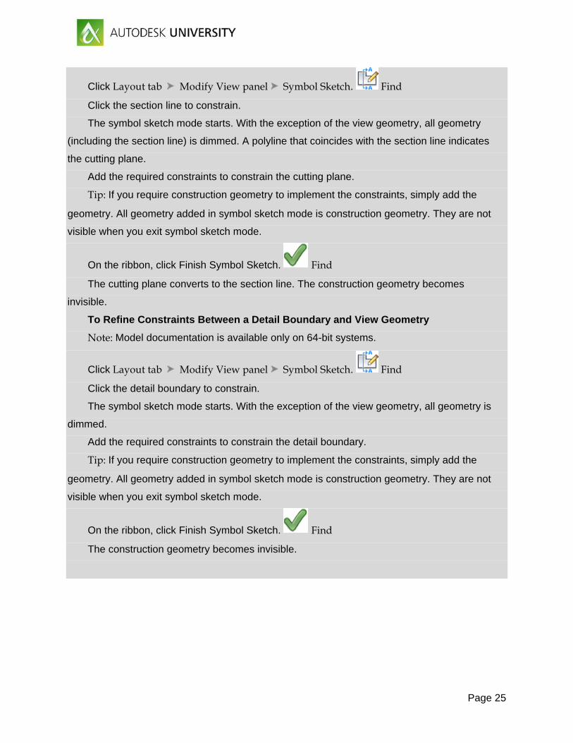
Click Layout tab Modify View panel Symbol Sketch. Find
Click the section line to constrain.
The symbol sketch mode starts. With the exception of the view geometry, all geometry
(including the section line) is dimmed. A polyline that coincides with the section line indicates
the cutting plane.
Add the required constraints to constrain the cutting plane.
Tip: If you require construction geometry to implement the constraints, simply add the
geometry. All geometry added in symbol sketch mode is construction geometry. They are not
visible when you exit symbol sketch mode.
On the ribbon, click Finish Symbol Sketch. Find
The cutting plane converts to the section line. The construction geometry becomes
invisible.
To Refine Constraints Between a Detail Boundary and View Geometry
Note: Model documentation is available only on 64-bit systems.
Click Layout tab Modify View panel Symbol Sketch. Find
Click the detail boundary to constrain.
The symbol sketch mode starts. With the exception of the view geometry, all geometry is
dimmed.
Add the required constraints to constrain the detail boundary.
Tip: If you require construction geometry to implement the constraints, simply add the
geometry. All geometry added in symbol sketch mode is construction geometry. They are not
visible when you exit symbol sketch mode.
On the ribbon, click Finish Symbol Sketch. Find
The construction geometry becomes invisible.