Embed Size (px)
Citation preview

EDITION 2004
The unique Databook containingcomprehensive information andComparison Tables on Sizes,weights and general data of Pipes,Tubes, Fittings, Flanges, Bars, Sheet& Strip, Hollow Sections and related products according to mainInternational Standards.
General catalogue
ContContentent
Content
2 General CatalogueGeneral Catalogue
Page 4 – 9 . . . . . . . . . . . . .Stainless SteelsChemical composition + Mechanical propertiesComparison of International standards
Page 10 - 29 . . . . . . . . . . .Nickel AlloysChemical composition + Mechanical propertiesComparison of International standards
Page 30-36 . . . . . . . . . . . .TitaniumChemical composition + Mechanical propertiesComparison of International standards
Page 37-38 . . . . . . . . . . . .Duplex and Superduplex Stainless Steelsand their caracteristics
Page 39-49 . . . . . . . . . . . .Special Stainless Steels – Technical Data
Page 50-55 . . . . . . . . . . . .Heatresisting Steels - Technical Data
Page 56 . . . . . . . . . . . . . . .Copper Alloys – Comparison DIN/EN stan-dards
Page 57 . . . . . . . . . . . . . . .Copper Alloys – Comparison Internationalstandards
Page 58-59 . . . . . . . . . . . .Aluminium – Comparison International standards
Page 60 . . . . . . . . . . . . . . .Aluminium – Temper designations
Page 61-65 . . . . . . . . . . . .Carbon or Alloy Steel Pipes – Technical Data
Page 66-70 . . . . . . . . . . . .Line Pipes Carbon Steel – Technical Data
Page 71 . . . . . . . . . . . . . . .Line Pipes Carbon Steel – Comparison ofInternational standards
Page 72-73 . . . . . . . . . . . .Furnace tubes for Refinery Service
Page 74 . . . . . . . . . . . . . . .Mills approvals
Page 75-81 . . . . . . . . . . . .Heatexchanger tubes – Stainless Steel
Page 82-83 . . . . . . . . . . . .Heatexchanger tubes – Nickel Alloys
Page 84-85 . . . . . . . . . . . .Heatexchanger tubes – Titanium
Page 86-89 . . . . . . . . . . . .Heatexchanger tubes – sizes, weights andtolerances
Page 90-94 . . . . . . . . . . . .Heatexchanger tubes – Inspection
Page 95 . . . . . . . . . . . . . . .Heatexchanger tubes – Production process
Page 96-99 . . . . . . . . . . . .Heatexchanger and Boiler tubes – Carbon and Alloy Steel
Page 100-104 . . . . . . . . . .Heatexchanger tubes – Brass and Copper Nickel
Page 105-107 . . . . . . . . . .Heatexchanger tubes – ex stock
Page 108-113 . . . . . . . . . . .U-bend heatexchanger tubes
Page 114 -115 . . . . . . . . . . .Heatexchanger tubes – Sizes and weights
Page 116-141 . . . . . . . . . . .Fin Tubes and Studded Tubes
Page 142-153 . . . . . . . . . .Steel tubes weights and sizes ANSI B 36.10, ANSI B 36.19
Page 154-155 . . . . . . . . . .Steel tubes weights and sizesDIN 2448 Seamless tubes
Page 156-157 . . . . . . . . . .Steel tubes weights and sizesDIN 2458 Welded tubes
Page 158-159 . . . . . . . . . .Hollow Bars weight and sizes
Page 160-161 . . . . . . . . . .Electric Resistance - Welded Steel Pipe & Tubes
Page 162-163 . . . . . . . . . . .Large Diameter Arc Welded Steel Pipe
Page 164 . . . . . . . . . . . . . .Butt Welded Steel Pipe
Page 165-166 . . . . . . . . . .Piping System Copper Nickel and Brass
Page 167 . . . . . . . . . . . . . .Dimensional tolerances MSS-SP43 andbevelled ends ANSI B16.9
Page 168- 179 . . . . . . . . . .Buttweld fittings ANSI B16.9Sizes and weights
Page 180-195 . . . . . . . . . . .Buttweld fittings DIN standardSizes and weights
Page 196-207 . . . . . . . . . .Forged Fittings Sizes ANSI B16.11 / MSS-SP 79 / MSS-SP 95
Page 208 . . . . . . . . . . . . . .Forged Fittings – weights
Page 209-211 . . . . . . . . . . .Weldolets / Threadolets / Sockolets
Page 212-247 . . . . . . . . . .Flanges ANSI B 16.5
Page 248-269 . . . . . . . . . .Flanges DIN Standards
Page 270-293 . . . . . . . . . .Valves
Page 294-297 . . . . . . . . . . .Extract of ferretic, martensic and ansteniticsteel plates and bars
Page 298-299 . . . . . . . . . .Nickel Alloy and Titanium Plates
Page 300-304 . . . . . . . . . .Plates and Tubesheets – Copper Alloys
Page 305-307 . . . . . . . . . . .Carbon and Alloy Steel Pressure Vessel Plates
Page 308-309 . . . . . . . . . .Nickel Alloy and Titanium Bars
Page 310-311 . . . . . . . . . . .Carbon and Alloy Steel Bars
Page 3112-314 . . . . . . . . . .Copper Alloy Bars
Page 315-317 . . . . . . . . . .Sizes and weights Bars / Strip / Plates
Page 318 . . . . . . . . . . . . . .Bevelled end standards
Page 319 . . . . . . . . . . . . . .Conversion tables – steel
Page 320 . . . . . . . . . . . . . .Freight cost calculation
Page 321-328 . . . . . . . . . . .EN Standards
Page 329-338 . . . . . . . . . . .ASTM Standards
General CatalogueGeneral Catalogue 3
TPS-Technitube has been founded 1975 in Ratingen near Düsseldorf. 2 years later the offices and production facilities were establishedin Daun/ Germany. This was the beginning of the production of tubular goods.
TPS is today a private owned, future orientated company, operating most modern worldwide renowned production mills for oil- and gasfield tubular products, for seamless tubes in alloy steel, stainless steels, nickel alloys and titanium gradesand non-ferrous metals. For extended surface tubes "Technifin" and "Technistud" as well as for fittings, flanges and other piping and tubing products and accessories.
The production mills of TPS-Technitube Röhrenwerke, located on a total industrial area ofmore than 600000 sq.ft in Daun, in the center of Europe, have an excellent worldwide reputa-tion as a reliable and competitive manufacturer of high quality piping and tubular goods.
Apart from the production facilities TPS is running stocks for immediate deliveries. Theplant facilities as well as the stock facilities allow TPS to serve customers worldwide withstandard mill deliverytimes as well as tubes from stock.
TPS supplies mainly to the Oil- & Gas Industry, Refineries, Fertilizer Plants, ChemicalPlants, Power Stations, Steel Mills, Heat Exchanger- and Boiler Manufacturers, SugarFactories, Machinery Plants and to the Automotive Industry.
TPS is certified by various inspection companies. We are holder of the API Licence Nr.5CT-0026, 5D-0012, 5L-0020; ISO 9001: 2000 and PED 97/23/EC; Framatome 1401,QSP 4a and AVS D 100 / 50; Germanischer Lloyd WZ 894HH1.
Our fully equiped inspection department is in a position to do all the necessary tests and to check and accept your special requirements.
TPS is also specialized in so called "Package Deals" for projects. The customer orders all material forone project from one source. The result is a heavy reduction in costs. From one source just in time simplifies the execution of a projectdrastically and saves costs considerably.
With this catalogue, TPS is giving complete information about the manufacturing and supply range of alloy steel, stainless steel, nickelalloys, titanium and non-ferrous metals from mill and ex stock.
For further information, please contact the following address or visit our website:
TPS-Technitube Röhrenwerke GmbHJulius-Saxler-Straße 7
D-54550 Daun
e-mail: [email protected]: www.TPS-Technitube.de
Tel. 0049 65 92 /712-0 Fax 0049 65 92 /13 05
SSttainless Sainless StteelseelsAUSTENITIC, FERRITIC AND MARTENSITIC STAINLESS STEEL
4 General CatalogueGeneral Catalogue
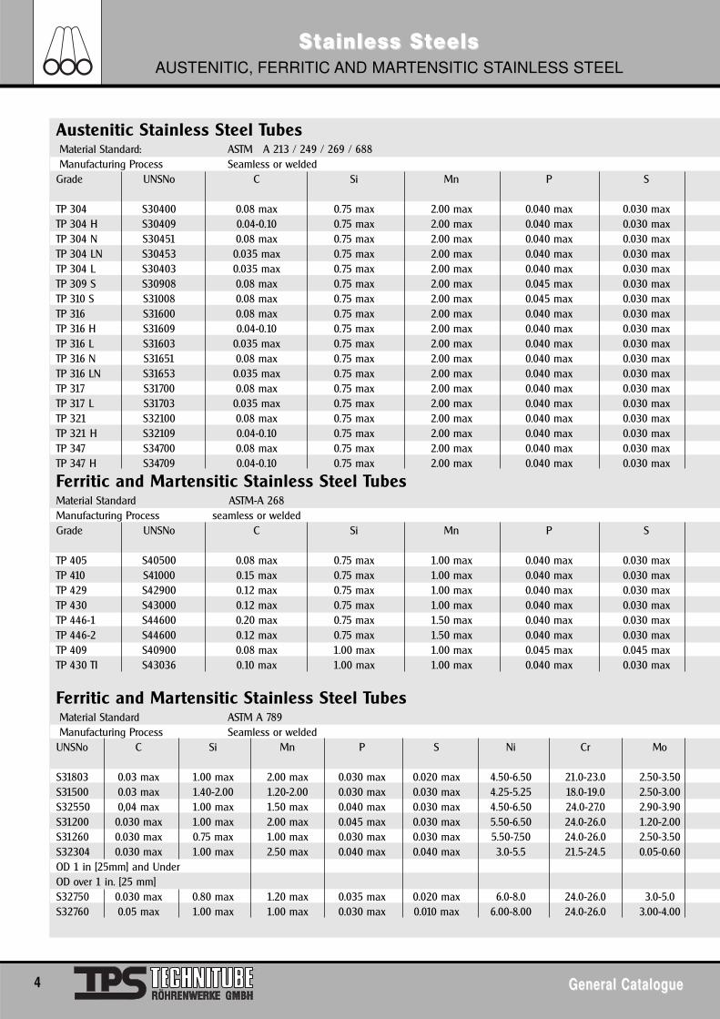
Austenitic Stainless Steel TubesMaterial Standard: ASTM A 213 / 249 / 269 / 688Manufacturing Process Seamless or welded
Grade UNSNo C Si Mn P S
TP 304 S30400 0.08 max 0.75 max 2.00 max 0.040 max 0.030 maxTP 304 H S30409 0.04-0.10 0.75 max 2.00 max 0.040 max 0.030 maxTP 304 N S30451 0.08 max 0.75 max 2.00 max 0.040 max 0.030 maxTP 304 LN S30453 0.035 max 0.75 max 2.00 max 0.040 max 0.030 maxTP 304 L S30403 0.035 max 0.75 max 2.00 max 0.040 max 0.030 maxTP 309 S S30908 0.08 max 0.75 max 2.00 max 0.045 max 0.030 maxTP 310 S S31008 0.08 max 0.75 max 2.00 max 0.045 max 0.030 maxTP 316 S31600 0.08 max 0.75 max 2.00 max 0.040 max 0.030 maxTP 316 H S31609 0.04-0.10 0.75 max 2.00 max 0.040 max 0.030 maxTP 316 L S31603 0.035 max 0.75 max 2.00 max 0.040 max 0.030 maxTP 316 N S31651 0.08 max 0.75 max 2.00 max 0.040 max 0.030 maxTP 316 LN S31653 0.035 max 0.75 max 2.00 max 0.040 max 0.030 maxTP 317 S31700 0.08 max 0.75 max 2.00 max 0.040 max 0.030 maxTP 317 L S31703 0.035 max 0.75 max 2.00 max 0.040 max 0.030 maxTP 321 S32100 0.08 max 0.75 max 2.00 max 0.040 max 0.030 maxTP 321 H S32109 0.04-0.10 0.75 max 2.00 max 0.040 max 0.030 maxTP 347 S34700 0.08 max 0.75 max 2.00 max 0.040 max 0.030 maxTP 347 H S34709 0.04-0.10 0.75 max 2.00 max 0.040 max 0.030 max
Ferritic and Martensitic Stainless Steel TubesMaterial Standard ASTM-A 268Manufacturing Process seamless or weldedGrade UNSNo C Si Mn P S
TP 405 S40500 0.08 max 0.75 max 1.00 max 0.040 max 0.030 maxTP 410 S41000 0.15 max 0.75 max 1.00 max 0.040 max 0.030 maxTP 429 S42900 0.12 max 0.75 max 1.00 max 0.040 max 0.030 maxTP 430 S43000 0.12 max 0.75 max 1.00 max 0.040 max 0.030 maxTP 446-1 S44600 0.20 max 0.75 max 1.50 max 0.040 max 0.030 maxTP 446-2 S44600 0.12 max 0.75 max 1.50 max 0.040 max 0.030 maxTP 409 S40900 0.08 max 1.00 max 1.00 max 0.045 max 0.045 maxTP 430 TI S43036 0.10 max 1.00 max 1.00 max 0.040 max 0.030 max
Ferritic and Martensitic Stainless Steel TubesMaterial Standard ASTM A 789Manufacturing Process Seamless or welded
UNSNo C Si Mn P S Ni Cr Mo
S31803 0.03 max 1.00 max 2.00 max 0.030 max 0.020 max 4.50-6.50 21.0-23.0 2.50-3.50S31500 0.03 max 1.40-2.00 1.20-2.00 0.030 max 0.030 max 4.25-5.25 18.0-19.0 2.50-3.00S32550 0,04 max 1.00 max 1.50 max 0.040 max 0.030 max 4.50-6.50 24.0-27.0 2.90-3.90S31200 0.030 max 1.00 max 2.00 max 0.045 max 0.030 max 5.50-6.50 24.0-26.0 1.20-2.00S31260 0.030 max 0.75 max 1.00 max 0.030 max 0.030 max 5.50-7.50 24.0-26.0 2.50-3.50S32304 0.030 max 1.00 max 2.50 max 0.040 max 0.040 max 3.0-5.5 21.5-24.5 0.05-0.60OD 1 in [25mm] and UnderOD over 1 in. [25 mm]S32750 0.030 max 0.80 max 1.20 max 0.035 max 0.020 max 6.0-8.0 24.0-26.0 3.0-5.0S32760 0.05 max 1.00 max 1.00 max 0.030 max 0.010 max 6.00-8.00 24.0-26.0 3.00-4.00
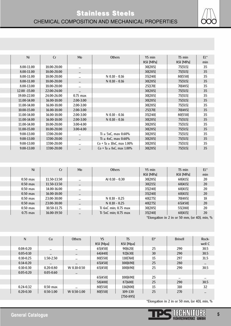
SSttainless Sainless StteelseelsCHEMICAL COMPOSITION AND MECHANICAL PROPERTIES
General CatalogueGeneral Catalogue 5
Ni Cr Mo Others YS min TS min El.*KSI [MPa] KSI [MPa] min
8.00-11.00 18.00-20.00 ... 30[205] 75[515] 358.00-11.00 18.00-20.00 ... 30[205] 75[515] 358.00-11.00 18.00-20.00 ... N 0.10 - 0.16 35[240] 80[550] 358.00-11.00 18.00-20.00 ... N 0.10 - 0.16 30[205] 75[515] 358.00-13.00 18.00-20.00 ... 25[170] 70[485] 35
12.00 -15.00 22.00-24.00 ... 30[205] 75[515] 3519.00-22.00 24.00-26.00 0.75 max 30[205] 75[515] 3511.00-14.00 16.00-18.00 2.00-3.00 30[205] 75[515] 3511.00-14.00 16.00-18.00 2.00-3.00 30[205] 75[515] 3510.00-15.00 16.00-18.00 2.00-3.00 25[170] 70[485] 3511.00-14.00 16.00-18.00 2.00-3.00 N 0.10 - 0.16 35[240] 80[550] 3511.00-14.00 16.00-18.00 2.00-3.00 N 0.10 - 0.16 30[205] 75[515] 3511.00-14.00 18.00-20.00 3.00-4.00 30[205] 75[515] 3511.00-15.00 18.00-20.00 3.00-4.00 30[205] 75[515] 359.00-13.00 17.00-20.00 ... Ti ≥ 5xC, max 0.60% 30[205] 75[515] 359.00-13.00 17.00-20.00 ... Ti ≥ 4xC, max 0.60% 30[205] 75[515] 359.00-13.00 17.00-20.00 ... Co + Ta ≥ 10xC, max 1.00% 30[205] 75[515] 359.00-13.00 17.00-20.00 ... Co + Ta ≥ 8xC, max 1.00% 30[205] 75[515] 35
Ni Cr Mo Others YS min TS min El.*KSI [MPa] KSI [MPa] min
0.50 max 11.50-13.50 ... Al 0.10 - 0.30 30[205] 60[415] 200.50 max 11.50-13.50 ... 30[215] 60[415] 200.50 max 14.00-16.00 ... 35[240] 60[415] 200.50 max 16.00-18.00 ... 35[240] 60[415] 200.50 max 23.00-30.00 ... N 0.10 - 0.25 40[275] 70[485] 180.50 max 23.00-30.00 ... N 0.10 - 0.25 40[275] 65[450] 200.50 max 10.50-11.75 ... Ti 6xC min; 0.75 max 30[205] 55[380] 200.75 max 16.00-19.50 ... Ti 5xC min; 0.75 max 35[240] 60[415] 20
*Elongation in 2 in or 50 mm, (or 4D), min, %
N Cu Others YS TS El* Brinell Rock-KSI [Mpa] KSI [Mpa] well C
0.08-0.20 ... ... 65[450] 90[620] 25 290 30.50.05-0.10 ... ... 64[440] 92[630] 30 290 30.50.10-0.25 1.50-2.50 ... 80[550] 110[760] 15 297 31.50.14-0.20 ... ... 65[450] 100[690] 25 280 ...0.10-0.30 0.20-0.80 W 0.10-0.50 65[450] 100[690] 25 290 30.50.05-0.20 0.05-0.60 ...
65[450] 100[690] 25 ... ...58[400] 87[600] 25 290 30.5
0.24-0.32 0.50 max ... 80[550] 116[800] 15 310 320.20-0.30 0.50-1.00 W 0.50-1.00 80[550] 109-130 25 270 ...
[750-895]*Elongation in 2 in or 50 mm, (or 4D), min, %
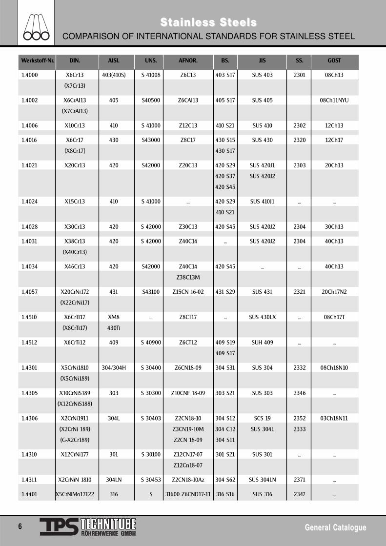
SSttainless Sainless StteelseelsCOMPARISON OF INTERNATIONAL STANDARDS FOR STAINLESS STEEL
6 General CatalogueGeneral Catalogue
Werkstoff-Nr. DIN. AISI. UNS. AFNOR. BS. JIS SS. GOST
1.4000 X6Cr13 403(410S) S 41008 Z6C13 403 S17 SUS 403 2301 08Ch13
(X7Cr13)
1.4002 X6CrAI13 405 S40500 Z6CAl13 405 S17 SUS 405 08Ch11NYU
(X7CrAl13)
1.4006 X10Cr13 410 S 41000 Z12C13 410 S21 SUS 410 2302 12Ch13
1.4016 X6Cr17 430 S43000 Z8C17 430 S15 SUS 430 2320 12Ch17
(X8Cr17] 430 S17
1.4021 X20Cr13 420 S42000 Z20C13 420 S29 SUS 420J1 2303 20Ch13
420 S37 SUS 420J2
420 S45
1.4024 X15Cr13 410 S 41000 ... 420 S29 SUS 410J1 ... ...
410 S21
1.4028 X30Cr13 420 S 42000 Z30C13 420 S45 SUS 420J2 2304 30Ch13
1.4031 X38Cr13 420 S 42000 Z40C14 ... SUS 420J2 2304 40Ch13
(X40Cr13)
1.4034 X46Cr13 420 S42000 Z40C14 420 S45 ... ... 40Ch13
Z38C13M
1.4057 X20CrNi172 431 S43100 Z15CN 16-02 431 S29 SUS 431 2321 20Ch17N2
(X22CrNi17)
1.4510 X6CrTi17 XM8 ... Z8CT17 ... SUS 430LX ... 08Ch17T
(X8CrTi17) 430Ti
1.4512 X6CrTi12 409 S 40900 Z6CT12 409 S19 SUH 409 ... ...
409 S17
1.4301 X5CrNi1810 304/304H S 30400 Z6CN18-09 304 S31 SUS 304 2332 08Ch18N10
(X5CrNi189)
1.4305 X10CrNiS189 303 S 30300 Z10CNF 18-09 303 S21 SUS 303 2346 ...
(X12CrNiS188)
1.4306 X2CrNi1911 304L S 30403 Z2CN18-10 304 S12 SCS 19 2352 03Ch18N11
(X2CrNi 189) Z3CN19-10M 304 C12 SUS 304L 2333
(G-X2Cr189) Z2CN 18-09 304 S11
1.4310 X12CrNi177 301 S 30100 Z12CN17-07 301 S21 SUS 301 ... ...
Z12Cn18-07
1.4311 X2CrNiN 1810 304LN S 30453 Z2CN18-10Az 304 S62 SUS 304LN 2371 ...
1.4401 X5CrNiMo17122 316 S 31600 Z6CND17-11 316 S16 SUS 316 2347 ...
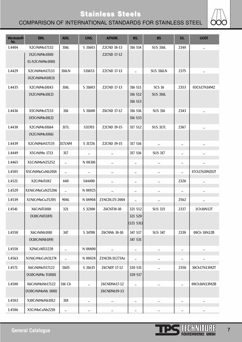
SSttainless Sainless StteelseelsCOMPARISON OF INTERNATIONAL STANDARDS FOR STAINLESS STEEL
General CatalogueGeneral Catalogue 7
Werkstoff- DIN. AISI. UNS. AFNOR. BS. JIS SS. GOST
1.4404 X2CrNiMo17132 316L S 31603 Z2CND 18-13 316 S14 SUS 316L 2348 ...
(X2CrNiMo1810) Z2CND 17-12
(G-X2CrNiMo1810)
1.4429 X2CrNiMoN17133 316LN S31653 Z2CND 17-13 ... SUS 316LN 2375 ...
(X2CrNiMoN1813)
1.4435 X2CrNiMo18143 316L S 31603 Z2CND 17-13 316 S11 SCS 16 2353 03Ch17N14M2
(X2CrNiMo1812) 316 S12 SUS 316L
316 S13
1.4436 X5CrNiMo17133 316 S 31600 Z6CND 17-12 316 S16 SUS 316 2343 ...
(X5CrNiMo1812) 316 S33
1.4438 X2CrNiMo18164 317L S31703 Z2CND 19-15 317 S12 SUS 317L 2367 ...
(X2CrNiMo1816)
1.4439 X2CrNiMoN17135 317LNM S 31726 Z2CND 19-15 317 S16 ... ... ...
1.4449 X5CrNiMo 1713 317 ... ... 317 S16 SUS 317 ... ...
1.4465 X1CrNiMoN25252 ... N 08310 ... ... ... ... ...
1.4505 X5CrNiMoCuNb2018 ... ... ... ... ... ... 07Ch17N20M2D2T
1.4521 X2CrMoTi182 440 S44400 ... ... ... 2326 ...
1.4529 X1NiCrMoCuN25206 ... N 08925 ... ... ... ... ...
1.4539 X1NiCrMoCu25205 904L N 08904 Z1NCDU25-2004 ... ... 2562 ...
1.4541 X6CrNiTi1810 321 S 32100 Z6CNT18-10 321 S12 SUS 321 2337 1Ch18N12T
(X10CrNiTi189) 321 S20
(321 S31)
1.4550 X6CrNiNb1810 347 S 34700 Z6CNNb 18-10 347 S17 SUS 347 2338 08Ch 18N12B
(X10CrNiNb189) 347 S31
1.4558 X2NiCrAITi3220 ... N 08800 ... ... ... ... ...
1.4563 X1NiCrMoCuN31274 ... N 08028 Z1NCDU31273Az ... ... ... ...
1.4571 X6CrNiMoTi17122 316Ti S 31635 Z6CNDT 17-12 320 S31 ... 2350 10Ch17N13M2T
(X10CrNiMo Ti1810) 320 S17
1.4580 X6CrNiMoNb17122 316 Cb ... Z6CNDNb17-12 ... ... ... 08Ch16N13M2B
(X10CrNiMoNb 1810) Z6CNDNb19-13
1.4583 X10CrNiMoNb1812 318 ... ... ... ... ... ...
1.4586 X5CrMoCuNb2218 ... ... ... ... ... ... ...
Nr.
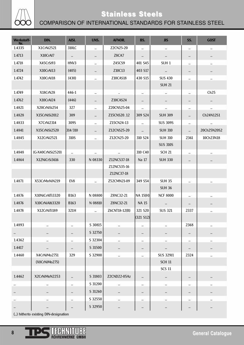
Werkstoff- DIN. AISI. UNS. AFNOR. BS. JIS SS. GOST
1.4335 X1CrNi2521 310LC ... Z2CN25-20 ... ... ... ...
1.4713 X10CrAI7 ... ... Z8CA7 ... ... ... ...
1.4718 X45CrSi93 HNV3 ... Z45CS9 401 S45 SUH 1 ... ...
1.4724 X10CrAl13 (405) ... Z10C13 403 S17 ... ... ...
1.4742 X10CrAl18 (430) ... Z10CAS18 430 S15 SUS 430 ... ...
SUH 21
1.4749 X18CrN28 446-1 ... .. ... ... ... Ch25
1.4762 X10CrAI24 (446) ... Z10CAS24 ... ... ... ...
1.4821 X20CrNiSi254 327 ... Z20CNS25-04 ... ... ... ...
1.4828 X15CrNiSi2012 309 ... Z15CNS20_12 309 S24 SUH 309 ... Ch24N12S1
1.4833 X7CrNi2314 309S ... Z15CN24-13 ... SUS 309S ... ...
1.4841 X15CrNiSi2520 314/310 ... Z12CNS25-20 ... SUH 310 ... 20Ch25N20S2
1.4845 X12CrNi2521 310S ... Z12CN25-20 310 S24 SUH 310 2361 10Ch23N18
SUS 310S
1.4848 (G-X40CrNiSi2520) ... ... ... 310 C40 SCH 21 ... ...
1.4864 X12NiCrSi3616 330 N 08330 Z12NCS37-18 Na 17 SUH 330 ... ...
Z12NCS35-16
Z12NC37-18
1.4871 X53CrMnNiN219 EV8 ... Z52CMN21-09 349 S54 SUH 35 ... ...
SUH 36
1.4876 X10NiCrAITi3320 B163 N 08800 Z8NC32-21 NA 15(H) NCF 8000 ... ...
1.4876 X10CrNiAIti3320 B163 N 08810 Z8NC32-21 NA 15 ... ... ...
1.4878 X12CrNiTi189 321H ... Z6CNT18-12(B) 321 S20 SUS 321 2337 ...
(321 S12)
1.4893 ... ... S 30815 ... ... ... 2368 ...
... ... ... S 32750 ... ... ... ... ...
1.4362 ... ... S 32304 ... ... ... ... ...
1.4417 ... ... S 31500 ... ... ... ... ...
1.4460 X4CrNiMo2751 329 S 32900 ... ... SUS 329J1 2324 ...
(X8CrNiMo275) SCH 11
SCS 11
1.4462 X2CrNiMoN2253 ... S 31803 Z2CND22-05Az ... ... ... ...
... ... ... S 31200 ... ... ... ... ...
... ... ... S 31260 ... ... ... ... ...
... ... ... S 32550 ... ... ... ... ...
... ... ... S 32950 ... ... ... ... ...
(...) hitherto existing DIN-designation
SSttainless Sainless StteelseelsCOMPARISON OF INTERNATIONAL STANDARDS FOR STAINLESS STEEL
8 General CatalogueGeneral Catalogue
Nr.
SSttainless Sainless StteelseelsFERRITIC AND FERRITIC-AUSTENITIC STEEL
General CatalogueGeneral Catalogue 9
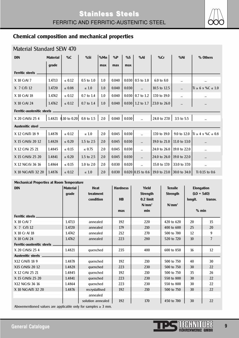
Chemical composition and mechanical properties
Material Standard SEW 470DIN Material %C %Si %Mn %P %S %Al %Cr %Ni % Others
grade max max max
Ferritic steels
X 10 CrAl 7 1.4713 ≤ 0.12 0.5 to 1.0 1.0 0.040 0.030 0.5 to 1.0 6.0 to 8.0 ... ...
X 7 CrTi 12 1.4720 ≤ 0.08 ≤ 1.0 1.0 0.040 0.030 ... 10.5 to 12.5 ... Ti ≥ 6 x %C ≤ 1.0
X 10 CrAl 18 1.4742 ≤ 0.12 0.7 to 1.4 1.0 0.040 0.030 0.7 to 1.2 17.0 to 19.0 ... ...
X 10 CrAl 24 1.4762 ≤ 0.12 0.7 to 1.4 1.0 0.040 0.030 1.2 to 1.7 23.0 to 26.0 ... ...
Ferritic-austenitic steels
X 20 CrNiSi 25 4 1.4821 0.10 to 0.20 0.8 to 1.5 2.0 0.040 0.030 ... 24.0 to 27.0 3.5 to 5.5 ...
Austenitic steel
X 12 CrNiTi 18 9 1.4878 ≤ 0.12 ≤ 1.0 2.0 0.045 0.030 ... 17.0 to 19.0 9.0 to 12.0 Ti ≥ 4 x %C ≤ 0.8
X 15 CrNiSi 20 12 1.4828 ≤ 0.20 1.5 to 2.5 2.0 0.045 0.030 ... 19.0 to 21.0 11.0 to 13.0 ...
X 12 CrNi 25 21 1.4845 ≤ 0.15 ≤ 0.75 2.0 0.045 0.030 ... 24.0 to 26.0 19.0 to 22.0 ...
X 15 CrNiSi 25 20 1.4841 ≤ 0.20 1.5 to 2.5 2.0 0.045 0.030 ... 24.0 to 26.0 19.0 to 22.0 ...
X 12 NiCrSi 36 16 1.4864 ≤ 0.15 1.0 to 2.0 2.0 0.030 0.020 ... 15.0 to 17.0 33.0 to 37.0 ...
X 10 NiCrAlTi 32 20 1.4876 ≤ 0.12 ≤ 1.0 2.0 0.030 0.020 0.15 to 0.6 19.0 to 23.0 30.0 to 34.0 Ti 0.15 to 0.6
Chemical composition and mechanical properties
Mechanical Properties at Room Temperature
DIN Material Heat Hardness Yield Tensile Elongation
grade treatment Strength Strength (LO = 5dO)
condition HB 0.2 limit longit. transv.
N/mm2 N/mm2
max min % min
Ferritic steels
X 10 CrAl 7 1.4713 annealed 192 220 420 to 620 20 15
X 7 CrTi 12 1.4720 annealed 179 210 400 to 600 25 20
X 10 Cr Al 18 1.4742 annealed 212 270 500 to 700 12 9
X 10 CrAl 24 1.4762 annealed 223 280 520 to 720 10 7
Ferritic-austenitic steels
X 20 CrNiSi 25 4 1.4821 quenched 235 400 600 to 850 16 12
Austenitic steels
X12 CrNiTi 18 9 1.4878 quenched 192 210 500 to 750 40 30
X15 CrNiSi 20 12 1.4828 quenched 223 230 500 to 750 30 22
X 12 CrNi 25 21 1.4845 quenched 192 210 500 to 750 35 26
X 15 CrNiSi 25 20 1.4841 quenched 223 230 550 to 800 30 22
X12 NiCrSi 36 16 1.4864 quenched 223 230 550 to 800 30 22
X 10 NiCrAiTi 32 20 1.4876 recrystallised 192 210 500 to 750 30 22
annealed
solution annealed 192 170 450 to 700 30 22
Abovementioned values are applicable only for samples ≥ 3 mm.
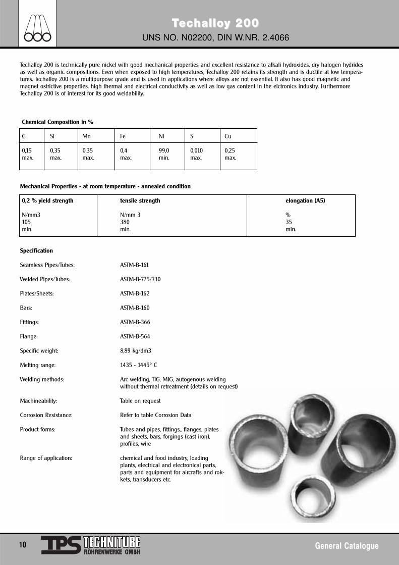
TTecechallohalloy 200y 200UNS NO. N02200, DIN W.NR. 2.4066
10 General CatalogueGeneral Catalogue
Techalloy 200 is technically pure nickel with good mechanical properties and excellent resistance to alkali hydroxides, dry halogen hydridesas well as organic compositions. Even when exposed to high temperatures, Techalloy 200 retains its strength and is ductile at low tempera-tures. Techalloy 200 is a multipurpose grade and is used in applications where alloys are not essential. It also has good magnetic andmagnet ostrictive properties, high thermal and electrical conductivity as well as low gas content in the elctronics industry. FurthermoreTechalloy 200 is of interest for its good weldability.
Chemical Composition in %
C Si Mn Fe Ni S Cu
0,15 0,35 0,35 0,4 99,0 0,010 0,25max. max. max. max. min. max. max.
Mechanical Properties - at room temperature - annealed condition
0,2 % yield strength tensile strength elongation (A5)
N/mm3 N/mm 3 %105 380 35min. min. min.
Specification
Seamless Pipes/Tubes: ASTM-B-161
Welded Pipes/Tubes: ASTM-B-725/730
Plates/Sheets: ASTM-B-162
Bars: ASTM-B-160
Fittings: ASTM-B-366
Flange: ASTM-B-564
Specific weight: 8,89 kg/dm3
Melting range: 1435 - 1445° C
Welding methods: Arc welding, TIG, MIG, autogenous weldingwithout thermal retreatment (details on request)
Machineability: Table on request
Corrosion Resistance: Refer to table Corrosion Data
Product forms: Tubes and pipes, fittings,, flanges, platesand sheets, bars, forgings (cast iron),profiles, wire
Range of application: chemical and food industry, loadingplants, electrical and electronical parts,parts and equipment for aircrafts and rok-kets, transducers etc.
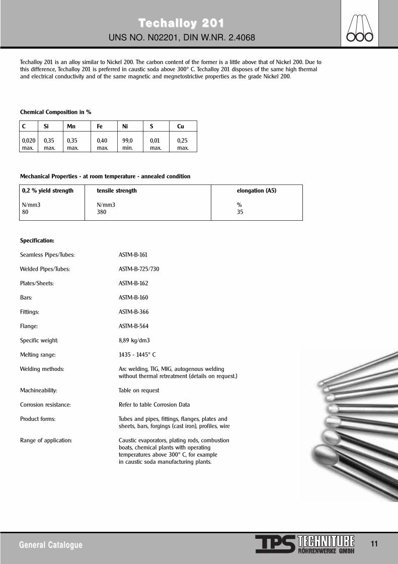
TTecechallohalloy 20y 2011UNS NO. N02201, DIN W.NR. 2.4068
General CatalogueGeneral Catalogue 11
Techalloy 201 is an alloy similar to Nickel 200. The carbon content of the former is a little above that of Nickel 200. Due tothis difference, Techalloy 201 is preferred in caustic soda above 300° C. Techalloy 201 disposes of the same high thermaland electrical conductivity and of the same magnetic and megnetostrictive properties as the grade Nickel 200.
Chemical Composition in %
C Si Mn Fe Ni S Cu
0,020 0,35 0,35 0,40 99,0 0,01 0,25max. max. max. max. min. max. max.
Mechanical Properties - at room temperature - annealed condition
0,2 % yield strength tensile strength elongation (A5)
N/mm3 N/mm3 %80 380 35
Specification:
Seamless Pipes/Tubes: ASTM-B-161
Welded Pipes/Tubes: ASTM-B-725/730
Plates/Sheets: ASTM-B-162
Bars: ASTM-B-160
Fittings: ASTM-B-366
Flange: ASTM-B-564
Specific weight: 8,89 kg/dm3
Melting range: 1435 - 1445° C
Welding methods: Arc welding, TIG, MIG, autogenous weldingwithout thermal retreatment (details on request.)
Machineability: Table on request
Corrosion resistance: Refer to table Corrosion Data
Product forms: Tubes and pipes, fittings, flanges, plates andsheets, bars, forgings (cast iron), profiles, wire
Range of application: Caustic evaporators, plating rods, combustionboats, chemical plants with operatingtemperatures above 300° C, for examplein caustic soda manufacturing plants.
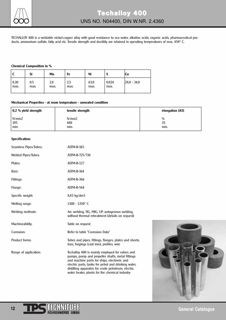
TTecechallohalloy 400y 400UNS NO. N04400, DIN W.NR. 2.4360
12 General CatalogueGeneral Catalogue
TECHALLOY 400 is a weldable nickel-copper alloy with good resistance to sea water, alkaline acids, organic acids, pharmaceutical pro-ducts, ammonium sulfate, fatty acid etc. Tensile strength and ductility are retained in operating temperatures of max. 450° C.
Chemical Composition in %
C Si Mn Fe Ni S Cu
0,30 0,5 2,0 2,5 63,0 0,024 28,0 - 34,0max. max. max. max. max. max.
Mechanical Properties - at room temperature - annealed condition
0,2 % yield strength tensile strength elongation (A5)
N/mm2 N/mm2 %195 480 35min. min. min.
Specification:
Seamless Pipes/Tubes: ASTM-B-165
Welded Pipes/Tubes: ASTM-B-725/730
Plates: ASTM-B-127
Bars: ASTM-B-164
Fittings: ASTM-B-366
Flange: ASTM-B-564
Specific weight: 8,83 kg/dm3
Melting range: 1300 - 1350° C
Welding methods: Arc welding, TIG, MIG, UP, autogenous welding,without thermal retreatment (details on request)
Machineability: Table on request
Corrosion: Refer to table "Corrosion Data"
Product forms: Tubes and pipes, fittings, flanges, plates and sheets,bars, forgings (cast iron), profiles, wire
Range of application: Techalloy 400 is mainly employed for valves andpumps, pump and propeller shafts, metal fittingsand machine parts for ships, electronic andelectric parts, tanks for petrol and drinking water,distilling apparatus for crude petroleum, electricwater heater, plants for the chemical industry
TTecechallohalloy K 500y K 500UNS NO. N05500, DIN W.NR. 2.4375
General CatalogueGeneral Catalogue 13
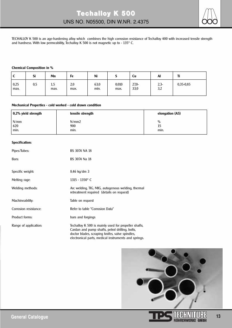
TECHALLOY K 500 is an age-hardening alloy which combines the high corrosion resistance of Techalloy 400 with increased tensile strengthand hardness. With low permeability, Techalloy K 500 is not magnetic up to - 135° C.
Chemical Composition in %
C Si Mn Fe Ni S Cu Al Ti
0,25 0,5 1,5 2,0 63,0 0,010 27,0- 2,3- 0,35-0,85max. max. max. min. max. 33,0 3,2
Mechanical Properties - cold worked - cold drawn condition
0,2% yield strength tensile strength elongation (A5)
N/mm N/mm2 %620 900 15min. min. min.
Specification:
Pipes/Tubes: BS 3074 NA 18
Bars: BS 3074 Na 18
Specific weight: 8,46 kg/dm 3
Melting rage: 1315 - 1350° C
Welding methods: Arc welding, TIG, MIG, autogenous welding, thermalretreatment required (details on request)
Machineability: Table on request
Corrosion resistance: Refer to table "Corrosion Data"
Product forms: bars and forgings
Range of application: Techalloy K 500 is mainly used for propeller shafts,Cardan and pump shafts, petrol drilling, bolts,doctor blades, scraping knifes, valve spindles,electronical parts, medical instruments and springs.
TTecechallohalloy 600y 600UNS NO. N06600, DIN W.NR. 2.4816
14 General CatalogueGeneral Catalogue
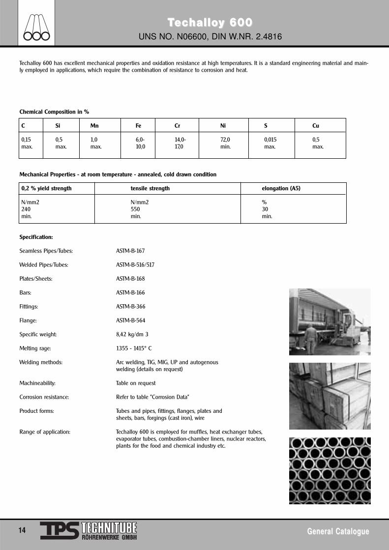
Techalloy 600 has excellent mechanical properties and oxidation resistance at high temperatures. It is a standard engineering material and main-ly employed in applications, which require the combination of resistance to corrosion and heat.
Chemical Composition in %
C Si Mn Fe Cr Ni S Cu
0,15 0,5 1,0 6,0- 14,0- 72,0 0,015 0,5max. max. max. 10,0 17,0 min. max. max.
Mechanical Properties - at room temperature - annealed, cold drawn condition
0,2 % yield strength tensile strength elongation (A5)
N/mm2 N/mm2 %240 550 30min. min. min.
Specification:
Seamless Pipes/Tubes: ASTM-B-167
Welded Pipes/Tubes: ASTM-B-516/517
Plates/Sheets: ASTM-B-168
Bars: ASTM-B-166
Fittings: ASTM-B-366
Flange: ASTM-B-564
Specific weight: 8,42 kg/dm 3
Melting rage: 1355 - 1415° C
Welding methods: Arc welding, TIG, MIG, UP and autogenouswelding (details on request)
Machineability: Table on request
Corrosion resistance: Refer to table "Corrosion Data"
Product forms: Tubes and pipes, fittings, flanges, plates andsheets, bars, forgings (cast iron), wire
Range of application: Techalloy 600 is employed for muffles, heat exchanger tubes,evaporator tubes, combustion-chamber liners, nuclear reactors,plants for the food and chemical industry etc.
TTecechallohalloy 60y 6011UNS NO. N06601, DIN W.NR. 2.4851
General CatalogueGeneral Catalogue 15
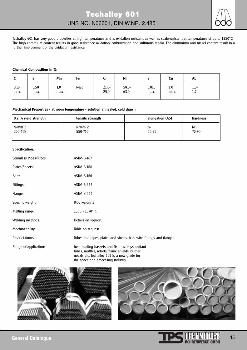
Techalloy 601 has very good properties at high temperatures and is oxidation resistant as well as scale-resistant at temperatures of up to 1250°C.The high chromium content results in good resistance oxidation, carburization and sulfurous media. The aluminium and nickel content result in afurther improvement of the oxidation resistance.
Chemical Composition in %
C Si Mn Fe Cr Ni S Cu AL
0,10 0,50 1,0 Rest 21,0- 58,0- 0,015 1,0 1,0-max. max. max. 25,0 63,0 max. max. 1,7
Mechanical Properties - at room temperature - solution annealed, cold drawn
0,2 % yield strength tensile strength elongation (A5) hardness
N/mm 2 N/mm 2 % RB205-415 550-760 65-35 70-95
Specification:
Seamless Pipes/Tubes: ASTM-B-167
Plates/Sheets: ASTM-B-168
Bars: ASTM-B-166
Fittings: ASTM-B-366
Flange: ASTM-B-564
Specific weight: 8,06 kg/dm 3
Melting range: 1300 - 1370° C
Welding methods: Details on request
Machineability: Table on request
Product forms: Tubes and pipes, plates and sheets, bars wire, fittings and flanges
Range of application: heat treating baskets and fixtures, trays, radianttubes, muffles, retorts, flame shields, burnernozzls etc. Techalloy 601 is a new grade forthe space and processing industry.
TTecechallohalloy 625y 625UNS NO. N06625, DIN W.NR. 2.4856
16 General CatalogueGeneral Catalogue
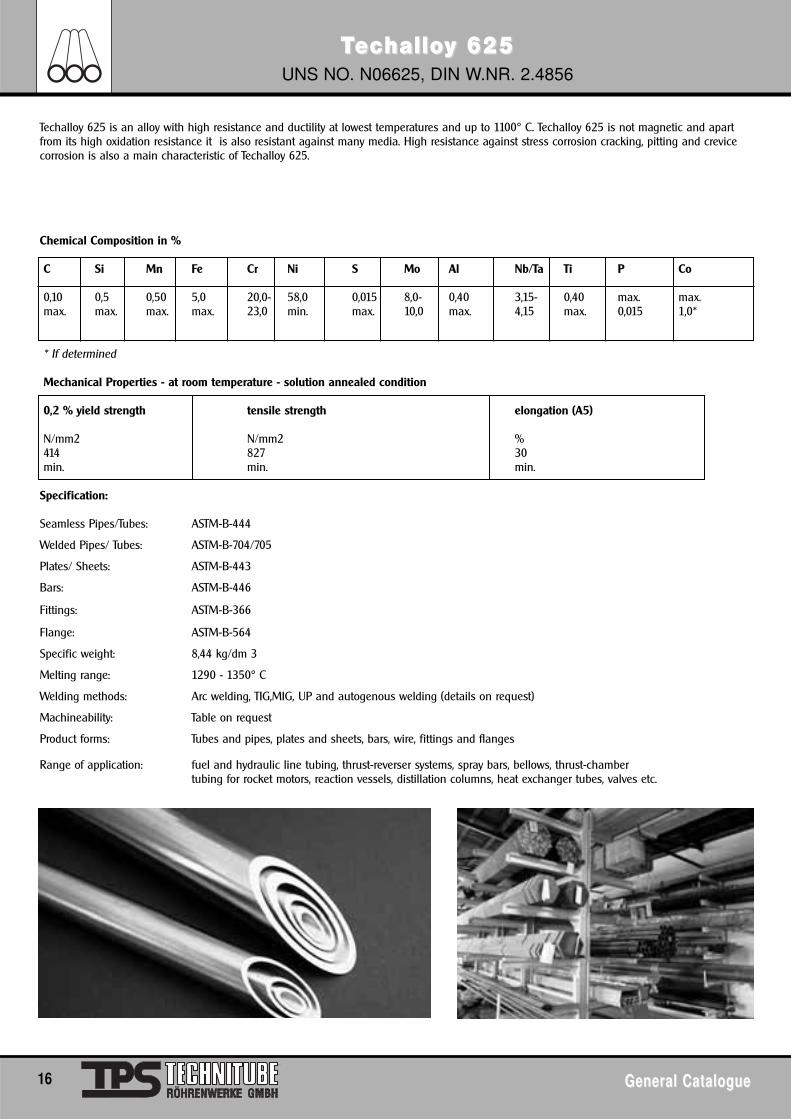
Techalloy 625 is an alloy with high resistance and ductility at lowest temperatures and up to 1100° C. Techalloy 625 is not magnetic and apartfrom its high oxidation resistance it is also resistant against many media. High resistance against stress corrosion cracking, pitting and crevicecorrosion is also a main characteristic of Techalloy 625.
Chemical Composition in %
C Si Mn Fe Cr Ni S Mo Al Nb/Ta Ti P Co
0,10 0,5 0,50 5,0 20,0- 58,0 0,015 8,0- 0,40 3,15- 0,40 max. max.max. max. max. max. 23,0 min. max. 10,0 max. 4,15 max. 0,015 1,0*
* If determined
Mechanical Properties - at room temperature - solution annealed condition
0,2 % yield strength tensile strength elongation (A5)
N/mm2 N/mm2 %414 827 30min. min. min.
Specification:
Seamless Pipes/Tubes: ASTM-B-444
Welded Pipes/ Tubes: ASTM-B-704/705
Plates/ Sheets: ASTM-B-443
Bars: ASTM-B-446
Fittings: ASTM-B-366
Flange: ASTM-B-564
Specific weight: 8,44 kg/dm 3
Melting range: 1290 - 1350° C
Welding methods: Arc welding, TIG,MIG, UP and autogenous welding (details on request)
Machineability: Table on request
Product forms: Tubes and pipes, plates and sheets, bars, wire, fittings and flanges
Range of application: fuel and hydraulic line tubing, thrust-reverser systems, spray bars, bellows, thrust-chambertubing for rocket motors, reaction vessels, distillation columns, heat exchanger tubes, valves etc.
TTecechallohalloy 800y 800UNS NO. N08800, DIN W.NR. 1.4876
General CatalogueGeneral Catalogue 17
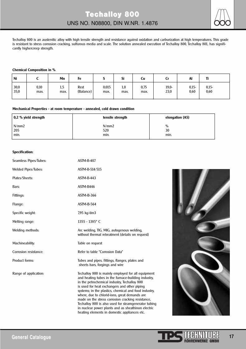
Techalloy 800 is an austenitic alloy with high tensile strength and resistance against oxidation and carburization at high temperatures. This gradeis resistant to stress corrosion cracking, sulfurous media and scale. The solution annealed execution of Techalloy 800, Techalloy 801, has signifi-cantly highercreep strength.
Chemical Composition in %
Ni C Mn Fe S Si Cu Cr Al Ti
30,0 0,10 1,5 Rest 0,015 1,0 0,75 19,0- 0,15- 0,15-35,0 max. max. (Balance) max. max. max. 23,0 0,60 0,60
Mechanical Properties - at room temperature - annealed, cold drawn condition
0,2 % yield strength tensile strength elongation (A5)
N/mm2 N/mm2 %205 520 30min. min. min.
Specification:
Seamless Pipes/Tubes: ASTM-B-407
Welded Pipes/Tubes: ASTM-B-514/515
Plates/Sheets: ASTM-B-443
Bars: ASTM-B446
Fittings: ASTM-B-366
Flange: ASTM-B-564
Specific weight: 7,95 kg/dm3
Melting range: 1355 - 1385° C
Welding methods: Arc welding, TIG, MIG, autogenous welding,without thermal retreatment (details on request)
Machineability: Table on request
Corrosion resistance: Refer to table "Corrosion Data"
Product forms: Tubes and pipes. fittings, flanges, plates andsheets bars, forgings and wire
Range of application: Techalloy 800 is mainly employed for all equipmentand heating tubes in the furnace-building industry,in the petrochemical industry, Techalloy 800is used for heat exchangers and other pipingsystems; in the plastics, chemical and food industry, where, due to chlorid-ions, great demands aremade on the stress corrosion cracking resistance, Techalloy 800 is also used for steamgenerator tubingin nuclear power plants and as sheathinon electricheating elements in domestic appliances etc.
TTecechallohalloy 800Hy 800HUNS NO. N08810, DIN W.NR. 1.4876
18 General CatalogueGeneral Catalogue
Techalloy 825 is a thermally stabilized alloy which is resistant to both inorganic and organic acids. It has excellent resistance to oxidizing andnonoxidizing hot acid conditions and at temperatures up to the boiling point it is resistant to many acids and alkaline solutions.
Chemical Composition in %
C Si Mn Fe Cr Ni S Cu Al Ti
0,05- 1,0 1,5 Rest 19,0- 30,0- 0,015 0,75 0,15- 0,15-0,10 max. max. 23,0 35,0 max. max. 0,60 0,60
Mechanical Properties - at room temperature - annealed condition, cold drawn
0,2 % yield strength tensile strength elongation (A5)
N/mm2 N/mm2 %170 450 30min. min. min.
Specification:
Seamless Pipes/Tubes: ASTM-B-407
Welded Pipes/Tubes: ASTM-B-514/515
Plates/Sheets: ASTM-B-409
Bars: ASTM-B-408
Fittings: ASTM-B-366
Flange: ASTM-B-564
Specific weight: 7,95 kg/dm3
Melting range: 1335- 1385° C
Welding methods: Arc welding and common welding processes
Machineability: Table on request
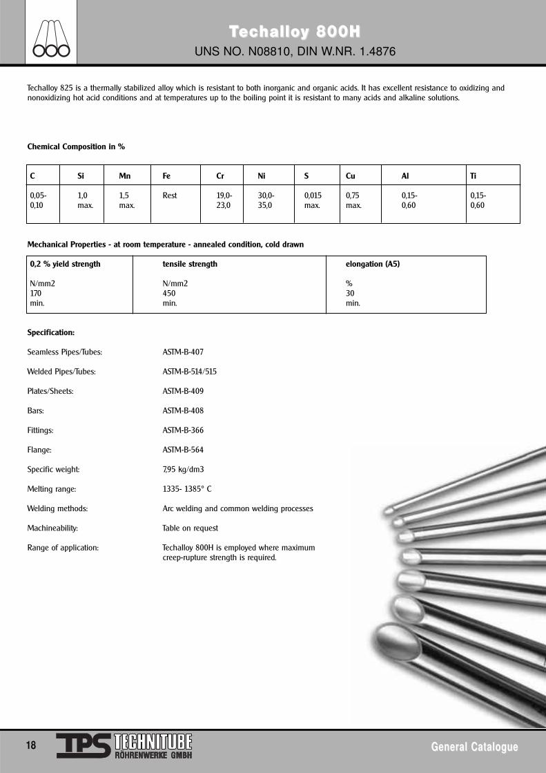
Range of application: Techalloy 800H is employed where maximumcreep-rupture strength is required.
TTecechallohalloy 825y 825UNS NO. N08825, DIN W.NR. 2.4858
General CatalogueGeneral Catalogue 19
Techalloy 825 is a thermally stabilized alloy which is resistant to both inorganic and organic acids. It has excellent resistance to oxidizing andnonoxidizing hot acid conditions and at temperatures up to the boiling point it is resistant to many acids and alkaline solutions.
Chemical Composition in %
C Si Mn Fe Cr Ni S Mo Cu Al Ti
0,025 0,5 1,0 Rest 19,5- 38,0-- 0,03 2,5- 1,5- 0,2 0,6-max. max. max. 23,5 46,0 max. 3,5 3,0 max. 1,2
Mechanical Properties - at room temperature - annealed condition, cold drawn
0,2 % yield strength tensile strength elongation (A5)
N/mm2 N/mm2 %241 586 30min. min. min.
Specification:
Seamless Pipes/Tubes: ASTM-B-423
Welded Pipes/Tubes: ASTM-B-704/705
Plates/Sheets: ASTM-B-424
Bars: ASTM-B-425
Fittings: ASTM-B-366
Flange: ASTM-B-564
Specific weight: 8,14 kg/dm3
Melting range: 1370 - 1400° C
Welding methods: Arc welding, TIG, MIG, plasma, autogenous welding (Details on request)Note: Take care that the surface is cleanedbefore welding
Machineability: Table on request
Corrosion resistance: Refer to table "Corrosion Data"
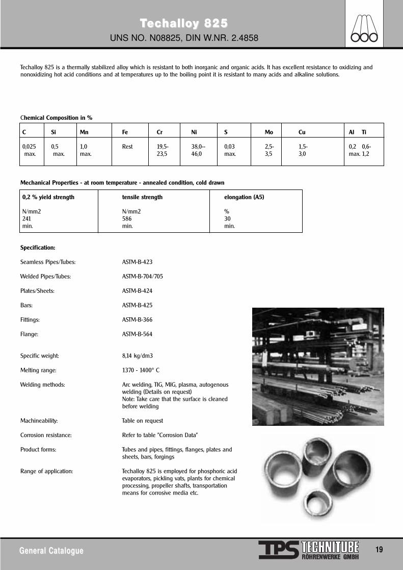
Product forms: Tubes and pipes, fittings, flanges, plates andsheets, bars, forgings
Range of application: Techalloy 825 is employed for phosphoric acidevaporators, pickling vats, plants for chemicalprocessing, propeller shafts, transportationmeans for corrosive media etc.
TTecechallohalloy B-2y B-2UNS NO. N10665, DIN W.NR. 2.4617
20 General CatalogueGeneral Catalogue
Techalloy B-2 is the further development of Techalloy B and has the same excellent corrosion resistance to boiling hydrochloric acid/hydrogenechloride and boiling sulfuric acid (up to a concentration of 60 %). Techalloy B-2 is resistant to carbide grain boundary separations in the heat-influenced welding zone so that it can be employed for most chemical applications without heat-treatment. Techalloy B-2 is furthermore resistantto stress corrosion cracking as well as pitting corrosion.
Chemical Composition: in %
C Si Mn Fe Cr Ni S P Mo Co
0,02 0,10 1,0 2,0 1,0 Rest 0,03 0,04 26-30 1,0max. max. max. max. max. max. max.. max.
Mechanical Properties - at room temperature - solution annealed condition
0,2 % yield strength tensile strength elongation (A5)
N/mm2 N/mm2 %352 760 40min. min. min.
Specification:
Seamless Pipes/Tubes: ASTM-B-622
Welded Pipes/Tubes: ASTM-B-619/626
Plates/Sheets: ASTM-B-333
Bars: ASTM-B-335
Fittings: ASTM-B-366
Flange: ASTM-B-564
Specific weight: 9,217 kg/dm3
Welding methods: Arc welding, TIG(Details on request)
Machineability: Details on request
Corrosion resistance: Refer to table TECHALLOY B-2
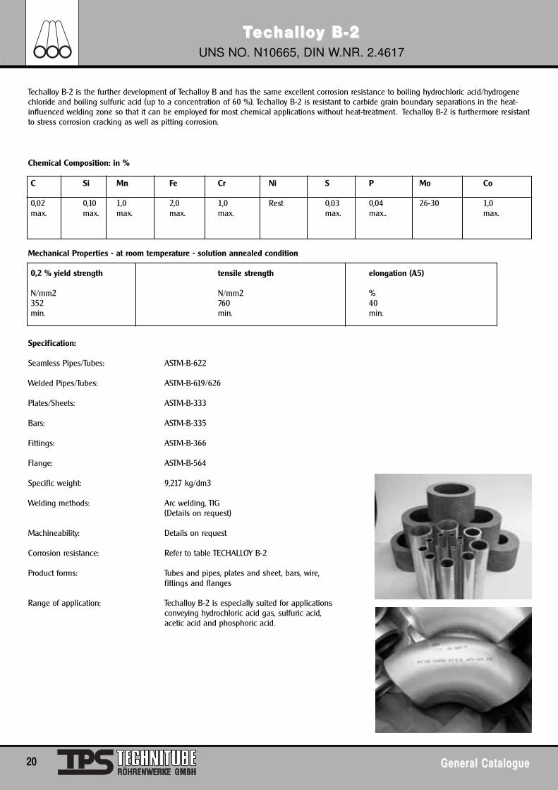
Product forms: Tubes and pipes, plates and sheet, bars, wire, fittings and flanges
Range of application: Techalloy B-2 is especially suited for applicationsconveying hydrochloric acid gas, sulfuric acid,acetic acid and phosphoric acid.
TTecechallohalloy C-2y C-27766UNS NO. N10276, DIN W.NR. 2.4819
General CatalogueGeneral Catalogue 21
Techalloy C-276 is the improved version of Techalloy C and is resistant to numerous media including strongly oxidizing chemicals (for exampleiron and cupric chloride) warm polluted acids, solvents, chloride and media contaminated by chloride (organic and inorganic), dry chloride, formicand acetic acid, acetic anhydride, sea water and saline solutions. Furthermore, Techalloy C-276 is resistant when exposed to damp chlorine gas,hypochlorite and chlorodioxide solutions. Techalloy C-276 combines this excellent corrosion resistance with immensely improved machineability.This alloy does not separate grain boundaries in the zone influenced by welding so that it is suited for most chemical applications even withoutheat-treatment.
Chemical Composition: in % max.
C Si Mn Fe Ni Cr S p Mo W Co V
0,01 0,08 1,0 4-7 57 14,5- 0,03 0,04 15-17 3-4,5 2,5 0,35max. max. max. Rest 16,5 max. max. max. max.
Mechanical Properties - at room temperature - solution annealed condition
0,2 % yield strength tensile strength elongation (A5)
N/mm2 N/mm2 %283 690 40min. min. min.
Specification:
Seamless Pipes/Tubes: ASTM-B.622
Welded Pipes/Tubes: ASTM-B-619/626
Plates/Sheets: ASTM-B-575
Fittings: ASTM-B-366
Flange: ASTM-B-564
Specific Weight: 8,88 kg/dm3
Melting range ca. 1323° Celsius
Welding methods: Arc welding. TIG (Details on request)
Machineability Table on request
Corrosion resistance Refer to table TECHALLOY C-276
Product forms: Tubes and pipes. sheets and plates. bars. wire and forgings, fittings and flanges
TTecechallohalloy C-4y C-4UNS NO. N06455, DIN W.NR. 2.4610
22 General CatalogueGeneral Catalogue
Techalloy C-4 is a relatively new Ni-Cr-Mo alloy with improved resistance at high temperatures. Even when used for a long period of time in thetemperature range of 650 - 1050° Celsius, this alloy retains its high ductility and corrosion resistance; furthermore it is highly resistant to grainboundsary separation in the heat-treated zone influenced by welding. Thus it can be employed without heatretreatment. Techalloy C-4 is alsohighly resistant against stress corrosion cracking and oxidizing atmospheres at temperatures up to 1050° Celsius.
Chemical Composition in %
C Si Mn Fe Cr Ni S P Mo Co Ti
0,015 0,08 1,0 3,0 14-18 Rest 0,03 0,04 14-17 2,0 0,70max. max. max. max. max. max. max. max.
Mechanical Properties - at room temperature - solution annealed condition
0,2 % yield strength tensile strength elongation (A5)
N/mm2 N/mm2 %276 690 40min. min. min.
Specification:
Pipes/Tubes: ASTM-B.622
Welded Pipes/Tubes: ASTM-B-619/626
Plates/Sheets ASTM-B-575
Fittings: ASTM-B-366
Flange: ASTM-B-564
Specific weight: 8,64 kg/dm3
Welding methods: Arc welding, TIG (Details on request)
Machineability: Details on request
Corrosion resistance: Refer to table TECHALLOY C-4
Product forms: Tubes and pipes, plates and sheet, bars, wire, forgings, fittings and flanges
TTecechallohalloy G3y G3UNS NO. N06985, DIN W.NR. 2.4619
General CatalogueGeneral Catalogue 23
Techalloy G3 is an Ni-Cr-Fe alloy with molybdenum and copper additions. This alloy is similar to Techalloy G. Techalloy G3 has excellent corrosionresistance to oxidizing chemicals. Due to its nickel and copper content, it is furthermoreresistant to reducing chemicals. Techalloy G3 is very sui-ted for evaporators, heat exchangers in air pollution control systems, tank liners etc.
Chemical Composition in %
Ni Cr Fe Mo Cu Nb/Ta CRest 21,0-23,0 18,0-21,0 6,0 - 8,0 1,5 - 2,5 0,50 0,015
max. max.
W Si Mn P S Co1,5 1,0 1,0 0,04 0,03 5,0max. max. max. max. max. max.
Mechanical Properties - at room temperature - annealed condition
0,2 % yield strength tensile strength elongation (A5)
N/mm2 N/mm2 %241 621 40,0min. min. min.
Specification:
Pipes/Tubes: ASTM-B-622
Welded Pipes/Tubes: ASTM-B-619/626
Sheets/Plates: ASTM-B-582
Fittings: ASTM-B-366
Flange: ASTM-B-564
Specific weight: 8,30 kg/dm3
Welding Methods: Arc welding
Machineability: Details on request
Product forms: Tubes and pipes, sheets, plates and strips, bars, fittings and flanges
Range of application: Flue gas desulfurization systems, air pollutioncontrol systems, evaporators, heat exchangers,tank liners etc.
TTecechallohalloy DSy DSDIN W.NR. 1.4864
24 General CatalogueGeneral Catalogue
Techalloy DS is a heat-resistant Ni-Cr-Fe alloy with Si-addition for the employment at high temperatures where sufficient strength and corrosionresistance are required. Techalloy DS is heat-resistant up to 1100° Celsius when in fresh air. This alloy is especially resistant against changingoxidizing/reducing conditions as well as against the formation of sigma phase in the critical temperature range of 590 to 870° Celsius.Furthermore it is resistant to green rot. Due to the high strength and heat resistance of Techalloy DS, smaller sections than usual can be manu-factured from this material.
Chemical Composition: in %
C Si Mn Fe Cr Ni Cu Ti S
0,1 1,9- 0,8- Rest 17,0- 34,5- 0,5 0,20 0,03max. 2,6 1,5 19,0 41,0 max. max.
Mechanical Properties - at room temperature - annealed condition
0,2 % yield strength tensile strength elongation
N/mm2 N/mm2 %363 687 50min. min. min.
Specification:
Pipes/Tubes: BS 3074 NA 17
Plates/Sheets: BS 3072/3073 Na 17
Specific weight: 7,92 kg/dm3
Melting range: 1330 - 1400° Celsius
Welding methods: Arc welding. TIG, MIG, plasma, autogenouswelding (Details on request)
Machineability: Table on request
Product forms Tubes and pipes. plates and sheets, bars. forgings
Range of application: Techalloy DS is mainly employed for all equipment and heating tubes in the furnace-building indu-stry, it is used in a multiplicity of heat-treatment applications, i.a. for thermocouple element shieldtubes etc.
TTecechallohalloy 20y 20UNS NO. N08020
General CatalogueGeneral Catalogue 25
Techalloy 20 is a high-alloyed stainless steel. Its corrosion properties surpass those of usual stainless qualities. For example, Techalloy 20 hasexcellent stress corrosion resistance to boiling 20-40% sulfuric acid. Although Techalloy 20 was originally developed for usage in sulfuric environ-ments. Its range of application has been steadily extended and today also includes machining of artificial rubber, plastics, synthetic fibers etc. Inpharmaceutical and food-producing applications, where purity has to be guaranteed. Techalloy 20 is employed to prevent metallic contamination.The most important advantages of this grade are its excellent mechanical properties as well as its comparatively easy machineability.
Chemical Composition: in %
C Si Mn Cr Ni S P Mo Cu Cb&Ta Fe
0.07 1.0 2.0 19-21 32.0- 0.035 0.045 2-3 3-4 8xC min. Restmax. max. max. 38.0 max. max. 1.0 max.
Mechanical Properties – at room temperature – annealed condition
0.2% yield strength tensile strength elongation (A5)
N/mm2 N/mm2 %241 551 30min. min. min.
Specification:
Seamless Pipes/Tubes: ASTM-B-729
Welded Pipes/Tubes: ASTM-B-464/468
Plates/Sheets: ASTM-B-463
Bars: ASTM-B-472/473
Fittings: ASTM-B-366
Flange: ASTM-B-564
Specific weight: 8.06 kg/dm2
Welding methods: Arc welding
Product forms: Tubes and pipes, sheets and plates, bars, wire, forgings
Range of application: Heat-exchangers, pickling vats, pump shafts.
TECTECHALLHALLOOY NICY NICKEL ALLKEL ALLOOYYSSCORROSION DATA
26 General CatalogueGeneral Catalogue
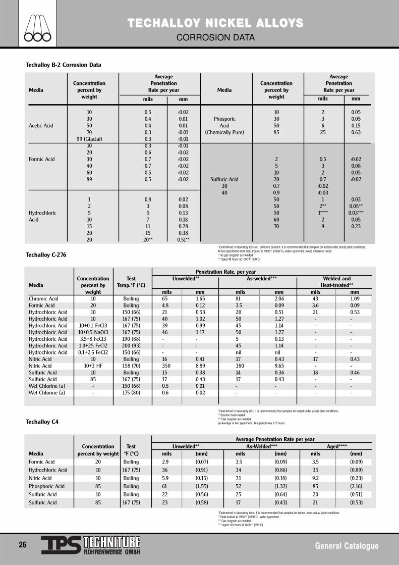
Average AverageConcentration Penetration Concentration Penetration
Media percent by Rate per year Media percent by Rate per yearweight mils mm weight mils mm
10 0.5 <0.02 10 2 0.0530 0.4 0.01 Phosporic 30 3 0.05
Acetic Acid 50 0.4 0.01 Acid 50 6 0.1570 0.3 <0.01 (Chemically Pure) 85 25 0.63
99 (Glacial) 0.3 <0.0110 0.3 <0.0120 0.6 <0.02
Formic Acid 30 0.7 <0.02 2 0.5 <0.0240 0.7 <0.02 5 3 0.0860 0.5 <0.02 10 2 0.0589 0.5 <0.02 Sulfuric Acid 20 0.7 <0.02
30 0.7 <0.0240 0.9 <0.03
1 0.8 0.02 50 1 0.032 3 0.08 50 2** 0.05**
Hydrochloric 5 5 0.13 50 1**** 0.03***Acid 10 7 0.18 60 2 0.05
15 11 0.28 70 9 0.2320 15 0.3820 20** 0.51**
Penetration Rate, per yearConcentration Test Unwelded** As-welded*** Welded and
Media percent by Temp.°F (°C) Heat-treated**weight mils mm mils mm mils mm
Chromic Acid 10 Boiling 65 1,65 81 2.06 43 1.09Formic Acid 20 Boiling 4.8 0.12 3.5 0.09 3.6 0.09Hydrochloric Acid 10 150 (66) 21 0.53 20 0.51 21 0.53Hydrochloric Acid 10 167 (75) 40 1.02 50 1.27 - -Hydrochloric Acid 10+0.1 FeCl3 167 (75) 39 0.99 45 1.14 - -Hydrochloric Acid 10+0.5 NaOCl 167 (75) 46 1.17 50 1.27 - -Hydrochloric Acid 3.5+8 FeCl3 190 (88) - - 5 0.13 - -Hydrochloric Acid 1.0+25 FeCl2 200 (93) - - 45 1.14 - -Hydrochloric Acid 0.1+2.5 FeCl2 150 (66) - - nil nil - -Nitric Acid 10 Boiling 16 0.41 17 0.43 17 0.43Nitric Acid 10+3 HF 158 (70) 350 8.89 380 9.65 - -Sulfuric Acid 10 Boiling 15 0.38 14 0.36 18 0.46Sulfuric Acid 85 167 (75) 17 0.43 17 0.43 - -Wet Chlorine (a) - 150 (66) 0.5 0.01 - - - -Wet Chlorine (a) - 175 (80) 0.6 0.02 - - - -
Average Penetration Rate per yearConcentration Test Unwelded** As-Welded*** Aged****
Media percent by weight °F (°C) mils (mm) mils (mm) mils (mm)
Formic Acid 20 Boiling 2.9 (0.07) 3.5 (0.09) 3.5 (0.09)
Hydrochloric Acid 10 167 (75) 36 (0.91) 34 (0.86) 35 (0.89)
Nitric Acid 10 Boiling 5.9 (0.15) 7.1 (0.18) 9.2 (0.23)
Phosphoric Acid 85 Boiling 61 (1.55) 52 (1.32) 85 (2.16)
Sulfuric Acid 10 Boiling 22 (0.56) 25 (0.64) 20 (0.51)
Sulfuric Acid 85 167 (75) 23 (0.58) 17 (0.43) 21 (0.53)
Techalloy B-2 Corrosion Data
Techalloy C-276
Techalloy C4
* Determined in laboratory tests of 120 hours duration. It is recommended that samples be tested under actual plant conditions.All test specimens were heat-treated at 1950°F (1066°C), water quenched unless otherwise noted.** As gas tungsten arc welded*** Aged 48 hours at 1000°F (538°C)
* Determined in laboratory test. It is recommended that samples be tested under actual plant conditions.** Solution heat-treated*** Gas tungsten-arc welded.(a) Average of two specimens. Test period was 210 hours.
* Determined in laboratory tests. It is recommended that samples be tested under actual plant conditions** Heat-treated at 1950°F (1066°C), water quenched.*** Gas tungsten-arc welded.**** Aged 100 hours at 1650°F (899°C)
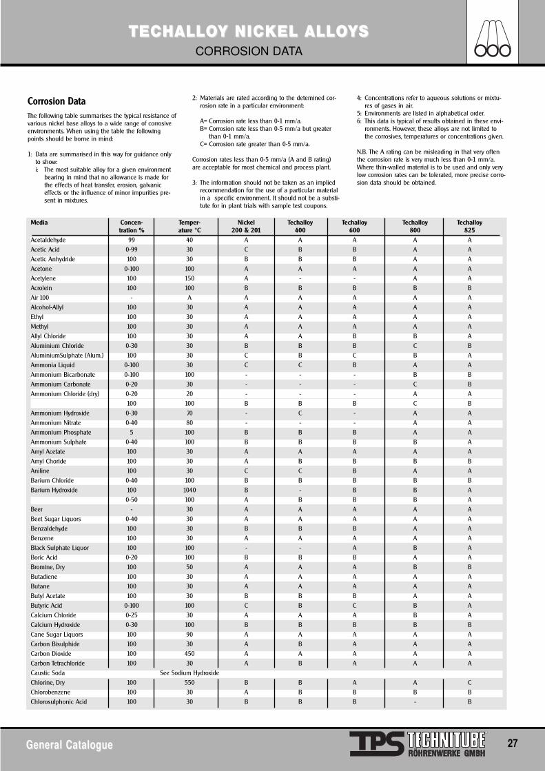
Media Concen- Temper- Nickel Techalloy Techalloy Techalloy Techalloytration % ature °C 200 & 201 400 600 800 825
Acetaldehyde 99 40 A A A A AAcetic Acid 0-99 30 C B B A AAcetic Anhydride 100 30 B B B A AAcetone 0-100 100 A A A A AAcetylene 100 150 A - - A AAcrolein 100 100 B B B B BAir 100 - A A A A A AAlcohol-Allyl 100 30 A A A A AEthyl 100 30 A A A A AMethyl 100 30 A A A A AAllyl Chloride 100 30 A A B B AAluminium Chloride 0-30 30 B B B C BAluminiumSulphate (Alum.) 100 30 C B C B AAmmonia Liquid 0-100 30 C C B A AAmmonium Bicarbonate 0-100 100 - - - B BAmmonium Carbonate 0-20 30 - - - C BAmmonium Chloride (dry) 0-20 20 - - - A A
100 100 B B B C BAmmonium Hydroxide 0-30 70 - C - A AAmmonium Nitrate 0-40 80 - - - A AAmmonium Phosphate 5 100 B B B A AAmmonium Sulphate 0-40 100 B B B B AAmyl Acetate 100 30 A A A A AAmyl Choride 100 30 A B B B BAniline 100 30 C C B A ABarium Chloride 0-40 100 B B B B BBarium Hydroxide 100 1040 B - B B A
0-50 100 A B B B ABeer - 30 A A A A ABeet Sugar Liquors 0-40 30 A A A A ABenzaldehyde 100 30 B B B A ABenzene 100 30 A A A A ABlack Sulphate Liquor 100 100 - - A B ABoric Acid 0-20 100 B B B A ABromine, Dry 100 50 A A A B BButadiene 100 30 A A A A AButane 100 30 A A A A AButyl Acetate 100 30 B B B A AButyric Acid 0-100 100 C B C B ACalcium Chloride 0-25 30 A A A B ACalcium Hydroxide 0-30 100 B B B B BCane Sugar Liquors 100 90 A A A A ACarbon Bisulphide 100 30 A B A A ACarbon Dioxide 100 450 A A A A ACarbon Tetrachloride 100 30 A B A A ACaustic Soda See Sodium HydroxideChlorine, Dry 100 550 B B A A CChlorobenzene 100 30 A B B B BChlorosulphonic Acid 100 30 B B B - B
TECTECHALLHALLOOY NICY NICKEL ALLKEL ALLOOYYSSCORROSION DATA
General CatalogueGeneral Catalogue 27
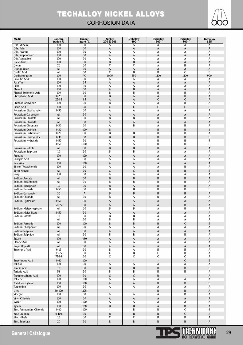
Corrosion DataThe following table summarises the typical resistance ofvarious nickel base alloys to a wide range of corrosiveenvironments. When using the table the followingpoints should be borne in mind:
1: Data are summarised in this way for guidance onlyto show:i: The most suitable alloy for a given environment
bearing in mind that no allowance is made forthe effects of heat transfer, erosion, galvaniceffects or the influence of minor impurities pre-sent in mixtures.
2: Materials are rated according to the detemined cor-rosion rate in a particular environment:
A= Corrosion rate less than 0-1 mm/a.B= Corrosion rate less than 0-5 mm/a but greater
than 0-1 mm/a.C= Corrosion rate greater than 0-5 mm/a.
Corrosion rates less than 0-5 mm/a (A and B rating)are acceptable for most chemical and process plant.
3: The information should not be taken as an impliedrecommendation for the use of a particular materialin a specific environment. It should not be a substi-tute for in plant trials with sample test coupons.
4: Concentrations refer to aqueous solutions or mixtu-res of gases in air.
5: Environments are listed in alphabetical order.6: This data is typical of results obtained in these envi-
ronments. However, these alloys are not limited tothe corrosives, temperatures or concentrations given.
N.B. The A rating can be misleading in that very oftenthe corrosion rate is very much less than 0-1 mm/a.Where thin-walled material is to be used and only verylow corrosion rates can be tolerated, more precise corro-sion data should be obtained.
Media Concen- Temper- Nickel Techalloy Techalloy Techalloy Techalloytration % ature °C 200 & 201 400 600 800 825
Chloroform 100 100 A A A A AChromic Acid 0-100 30 C C C C BCitric Acid 100 30 B B B B ACoffee - 100 A A A A ACopper Sulphate 0-30 100 C C C B ACresylic Acid 100 30 B B B B BDichlorethane 100 30 A A A B A
100 700 - - A A -Ethyl Acetate 100 30 B B B B AEthyl Cellulose All 30 B B B B AEthyl Chloride 100 30 A A A A AEthylene Dichloride 100 30 A A A B A
100 700 - - A A -Ethylene Glycol 100 30 B B B A AFatty Acids 100 30 A A A A AFerric Chloride 100 30 C C C C BFerric Nitrate 100 30 C C C B AFerric Sulphate 0-30 30 C B C B AFluoboric Acid 25 30 B B B B BFluosilicic Acid 20 30 B C B B BFormaldehyde 0-100 30 A A A A AFormic Acid 0-100 100 B B B C AFuel Oil 100 30 C A C A AFurfural 30-100 100 B B B B AGelantine 0-40 50 B B A A AGlucose All 30 A A A A AGlutamic Acid All 30 B B B B AGlycerine 100 30 A A A A AGlycerol 0-100 150 A A A A AHigh Temperature Salt(nitrate/nitrite) - 500 A - A A -Hydraulic Oil - - A A A A AHydrazine 100 35 C C C C CHydrobromic Acid - - C C C C CHydrochloric Acid 0-37 35Hydrocyanic Acid 100 35 C C A A AHydrofluoric Acid 10-100 35 B A B C B
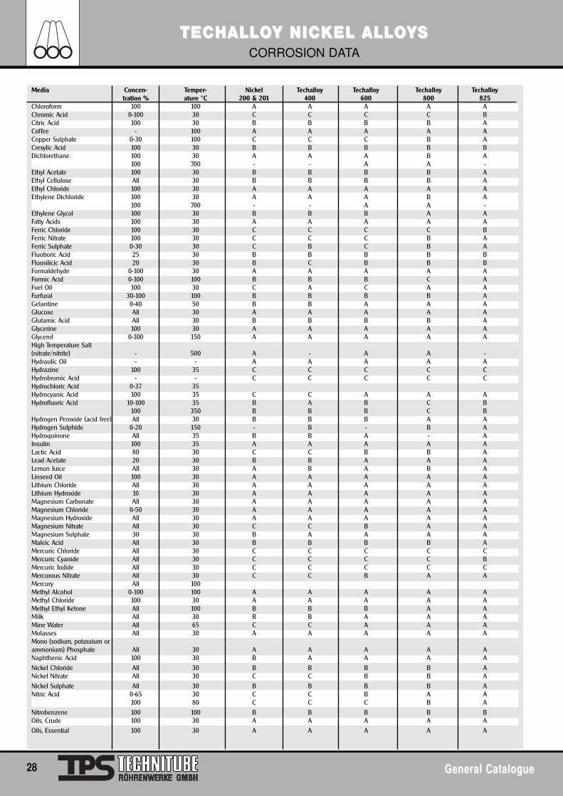
100 350 B B B C BHydrogen Peroxide (acid free) All 30 B B B A AHydrogen Sulphide 0-20 150 - B - B AHydroquinone All 35 B B A - AInsulin 100 35 A A A A ALactic Acid 80 30 C C B B ALead Acetate 20 30 B B A A ALemon Juice All 30 A B A B ALinseed Oil 100 30 A A A A ALithium Chloride All 30 A A A A ALithium Hydroxide 10 30 A A A A AMagnesium Carbonate All 30 A A A A AMagnesium Chloride 0-50 30 A A A A AMagnesium Hydroxide All 30 A A A A AMagnesium Nitrate All 30 C C B A AMagnesium Sulphate 30 30 B A A A AMaleic Acid All 30 B B B B AMercuric Chloride All 30 C C C C CMercuric Cyanide All 30 C C C C BMercuric Iodide All 30 C C C C CMercurous Nitrate All 30 C C B A AMercury All 100Methyl Alcohol 0-100 100 A A A A AMethyl Chloride 100 30 A A A A AMethyl Ethyl Ketone All 100 B B B A AMilk All 30 B B A A AMine Water All 65 C C A A AMolasses All 30 A A A A AMono (sodium, potassium orammonium) Phosphate All 30 A A A A ANaphthenic Acid 100 30 B A A A ANickel Chloride All 30 B B B B ANickel Nitrate All 30 C C B B ANickel Sulphate All 30 B B B B ANitric Acid 0-65 30 C C B A A
100 80 C C C B ANitrobenzene 100 100 B B B B BOils, Crude 100 30 A A A A AOils, Essential 100 30 A A A A A
TECTECHALLHALLOOY NICY NICKEL ALLKEL ALLOOYYSSCORROSION DATA
28 General CatalogueGeneral Catalogue
TECTECHALLHALLOOY NICY NICKEL ALLKEL ALLOOYYSSCORROSION DATA
General CatalogueGeneral Catalogue 29
Media Concen- Temper- Nickel Techalloy Techalloy Techalloy Techalloytration % ature °C 200 & 201 400 600 800 825
Oils, Mineral 100 30 A A A A AOils, Palm 100 30 A A A A AOils, Peanut 100 30 A A A A AOils, Sulphonated 100 30 A A A A AOils, Vegetable 100 30 A A A A AOleic Acid 100 30 B B A A AOleum 20 30 C C A B AOrange Juice All 30 A A A A AOxalic Acid All 30 C B B C BOxidising gases 100 °C 1000 550 1100 1100 900Palmitic Acid 100 30 A A A A AParaffin 100 35 A A A A APetrol 100 30 A A A A APhenol 100 30 A B A A APhenol Sulphonic Acid 100 30 B B B B APhosphoric Acid 0-25 30 B A A B A
25-85 85 A A C C APhthalic Anhydride 100 30 B A A B APicric Acid 100 30 C C C C BPotassium Bicarbonate 0-30 30 A A A A APotassium Carbonate All 30 A A A A APotassium Chlorate All 30 B B B B APotassium Chloride All 30 A A A A APotassium Chromate 0-30 30 A B A B APotassium Cyanide 0-30 100 B - B B BPotassium Dichromate 0-20 30 B B B B APotassium Ferricyanide 0-30 30 B B B B BPotassium Hydroxide 0-50 30 A A B B B
0-50 100 A A B B BPotassium Nitrate All 30 B B B A APotassium Sulphate 10 30 B B A A APropane 100 100 A A A A ASalicylic Acid All 30 A A A A ASea Water 100 100 A A A A ASilicon Tetrachloride 100 30 A A A B ASilver Nitrate All 30 C C B B BSoap 100 30 A A A A ASodium Acetate All 30 B B B B ASodium Bicarbonate All 30 B B B B ASodium Bisulphate 10 30 B A B B ASodium Bromide 0-50 30 B B B B BSodium Carbonate 30 A B B B B ASodium Chloride All 30 B A B A ASodium Hydroxide 0-50 30 A A A A A
50-75 30 A A A B ASodium Metaphosphate All 30 B B A B ASodium Metasilicate 0-50 30 A A A A ASodium Nitrate 10 30 B B A A A
All 30 B B A A ASodium Peroxide 100 100 B B B C BSodium Phosphate All 30 A A A A ASodium Sulphate All 30 A A A A ASodium Sulphide All 30 B B A B ASteam 100 450 A A A A AStearic Acid All 30 A A A A ASugar (liquid) All 30 A A A A ASulphuric Acid 0-15 30 B A B B A
15-75 30 C B C B A75-96 30 C C C C A
Sulphurous Acid 0-60 100 - - - C BTall Oil 100 30 A A A A ATannic Acid 10 30 B B B B BTartaric Acid 58 30 B B B B ATetraphosphoric Acid 100 30 C C B - AToluene 100 100 A A A A ATrichloroethylene 100 100 A A B B BTurpentine 100 30 A A A A AUrea 50-100 375 - - B B AVinegar 100 30 A A A B AVinyl Chloride 100 30 A A A A AWater 100 100 A A A A AXylene 100 100 B B A B AZinc Ammonium Chloride 0-40 100 - B B C BZinc Chloride 0-100 30 B B B C BZinc Nitrate 10 30 C C B B AZinc Sulphate 20 30 B B B B A
TTititanium and Tanium and Tititanium Alloanium Alloyyss
30 General CatalogueGeneral Catalogue
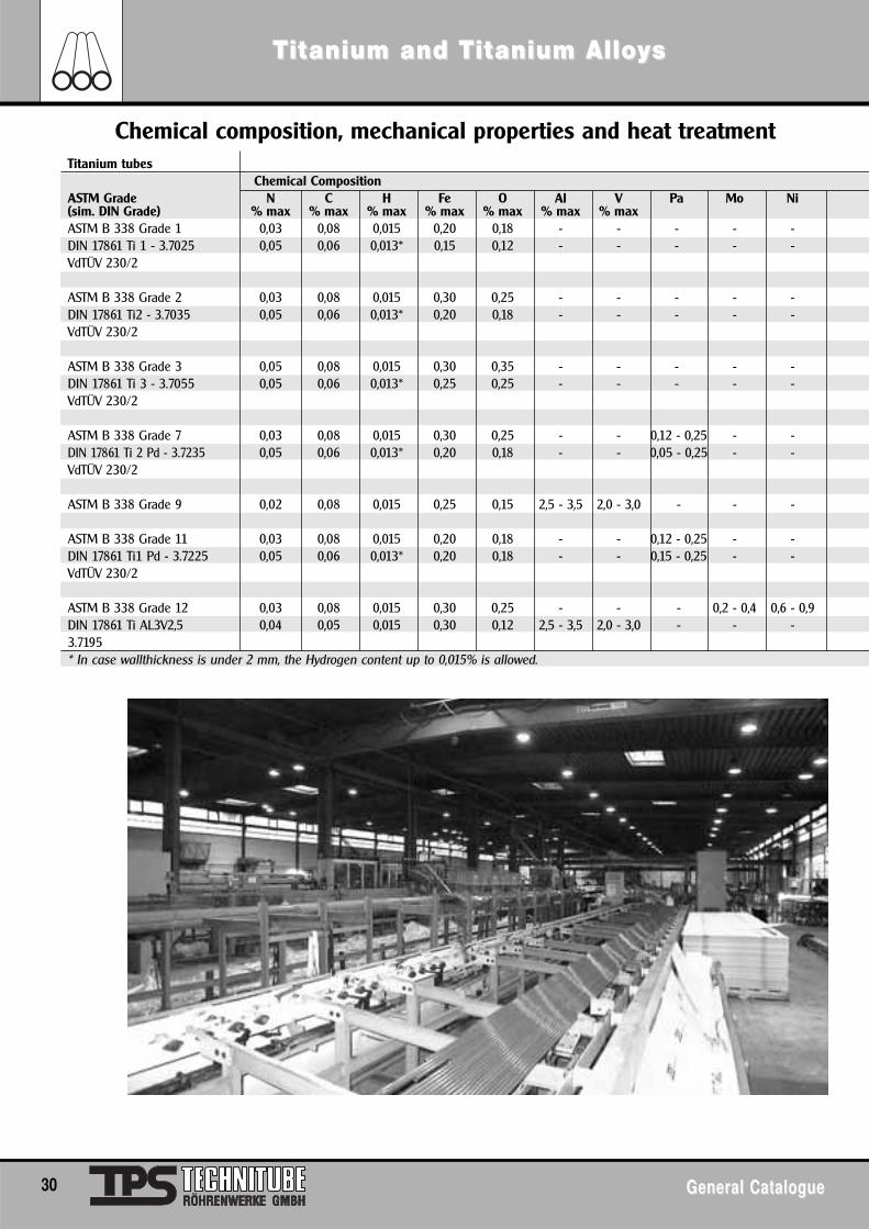
Titanium tubesChemical Composition
ASTM Grade N C H Fe O Al V Pa Mo Ni(sim. DIN Grade) % max % max % max % max % max % max % maxASTM B 338 Grade 1 0,03 0,08 0,015 0,20 0,18 - - - - -DIN 17861 Ti 1 - 3.7025 0,05 0,06 0,013* 0,15 0,12 - - - - -VdTÜV 230/2
ASTM B 338 Grade 2 0,03 0,08 0,015 0,30 0,25 - - - - -DIN 17861 Ti2 - 3.7035 0,05 0,06 0,013* 0,20 0,18 - - - - -VdTÜV 230/2
ASTM B 338 Grade 3 0,05 0,08 0,015 0,30 0,35 - - - - -DIN 17861 Ti 3 - 3.7055 0,05 0,06 0,013* 0,25 0,25 - - - - -VdTÜV 230/2
ASTM B 338 Grade 7 0,03 0,08 0,015 0,30 0,25 - - 0,12 - 0,25 - -DIN 17861 Ti 2 Pd - 3.7235 0,05 0,06 0,013* 0,20 0,18 - - 0,05 - 0,25 - -VdTÜV 230/2
ASTM B 338 Grade 9 0,02 0,08 0,015 0,25 0,15 2,5 - 3,5 2,0 - 3,0 - - -
ASTM B 338 Grade 11 0,03 0,08 0,015 0,20 0,18 - - 0,12 - 0,25 - -DIN 17861 Ti1 Pd - 3.7225 0,05 0,06 0,013* 0,20 0,18 - - 0,15 - 0,25 - -VdTÜV 230/2
ASTM B 338 Grade 12 0,03 0,08 0,015 0,30 0,25 - - - 0,2 - 0,4 0,6 - 0,9DIN 17861 Ti AL3V2,5 0,04 0,05 0,015 0,30 0,12 2,5 - 3,5 2,0 - 3,0 - - -3.7195* In case wallthickness is under 2 mm, the Hydrogen content up to 0,015% is allowed.
Chemical composition, mechanical properties and heat treatment
TTititanium and Tanium and Tititanium Alloanium Alloyyss
General CatalogueGeneral Catalogue 31
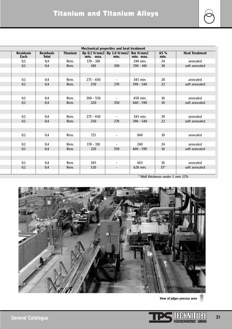
View of pilger process area ➠
Mechanical properties and heat treatmentResiduals Residuals Titanium Rp 0,2 N/mm2 Rp 1,0 N/mm2 Rm N/mm2 A5 % Heat Treatment
Each Total min. max. min. min. max. min.0,1 0,4 Rem. 170 - 310 - 240 min. 24 annealed0,1 0,4 Rem. 180 200 290 - 410 30 soft annealed
0,1 0,4 Rem. 275 - 450 - 345 min. 20 annealed0,1 0,4 Rem. 250 270 390 - 540 22 soft annealed
0,1 0,4 Rem. 380 - 550 - 450 min. 18 annealed0,1 0,4 Rem. 320 350 460 - 590 18 soft annealed
0,1 0,4 Rem. 275 - 450 - 345 min. 20 annealed0,1 0,4 Rem. 250 270 390 - 540 22 soft annealed
0,1 0,4 Rem. 725 - 860 10 annealed
0,1 0,4 Rem. 170 - 310 - 240 24 annealed0,1 0,4 Rem. 320 350 460 - 590 18 soft annealed
0,1 0,4 Rem. 345 - 483 18 annealed0,1 0,4 Rem. 520 - 620 min. 15* soft annealed
* Wall thickness under 1 mm 12%
TTititanium and Tanium and Tititanium Alloanium Alloyyss
32 General CatalogueGeneral Catalogue
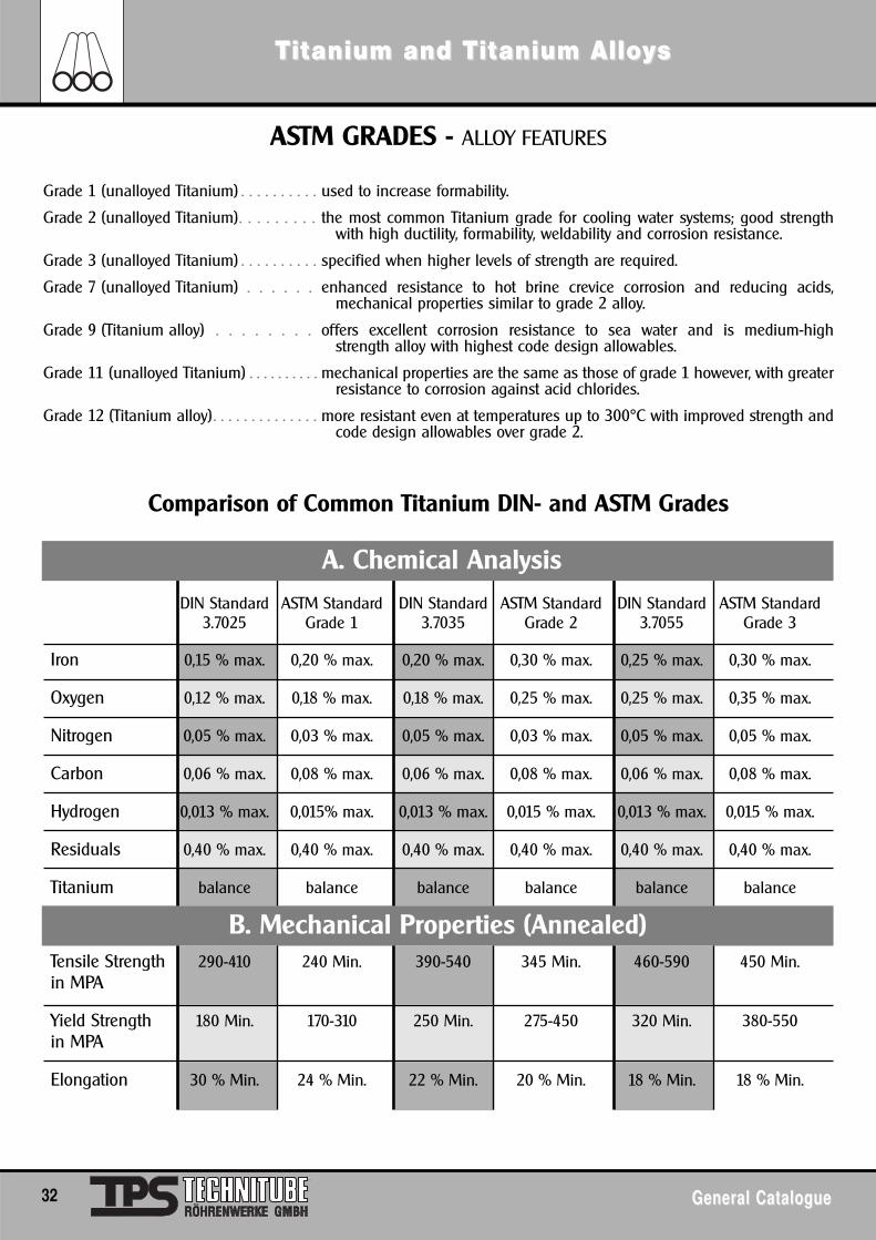
A. Chemical Analysis
B. Mechanical Properties (Annealed)
Comparison of Common Titanium DIN- and ASTM Grades
ASTM GRADES - ALLOY FEATURES
Grade 1 (unalloyed Titanium) . . . . . . . . . . used to increase formability.
Grade 2 (unalloyed Titanium). . . . . . . . . the most common Titanium grade for cooling water systems; good strengthwith high ductility, formability, weldability and corrosion resistance.
Grade 3 (unalloyed Titanium) . . . . . . . . . . specified when higher levels of strength are required.
Grade 7 (unalloyed Titanium) . . . . . . enhanced resistance to hot brine crevice corrosion and reducing acids,mechanical properties similar to grade 2 alloy.
Grade 9 (Titanium alloy) . . . . . . . . offers excellent corrosion resistance to sea water and is medium-highstrength alloy with highest code design allowables.
Grade 11 (unalloyed Titanium) . . . . . . . . . . mechanical properties are the same as those of grade 1 however, with greaterresistance to corrosion against acid chlorides.
Grade 12 (Titanium alloy) . . . . . . . . . . . . . . more resistant even at temperatures up to 300°C with improved strength andcode design allowables over grade 2.
DIN Standard ASTM Standard DIN Standard ASTM Standard DIN Standard ASTM Standard3.7025 Grade 1 3.7035 Grade 2 3.7055 Grade 3
Iron 0,15 % max. 0,20 % max. 0,20 % max. 0,30 % max. 0,25 % max. 0,30 % max.
Oxygen 0,12 % max. 0,18 % max. 0,18 % max. 0,25 % max. 0,25 % max. 0,35 % max.
Nitrogen 0,05 % max. 0,03 % max. 0,05 % max. 0,03 % max. 0,05 % max. 0,05 % max.
Carbon 0,06 % max. 0,08 % max. 0,06 % max. 0,08 % max. 0,06 % max. 0,08 % max.
Hydrogen 0,013 % max. 0,015% max. 0,013 % max. 0,015 % max. 0,013 % max. 0,015 % max.
Residuals 0,40 % max. 0,40 % max. 0,40 % max. 0,40 % max. 0,40 % max. 0,40 % max.
Titanium balance balance balance balance balance balance
Tensile Strength 290-410 240 Min. 390-540 345 Min. 460-590 450 Min.in MPA
Yield Strength 180 Min. 170-310 250 Min. 275-450 320 Min. 380-550in MPA
Elongation 30 % Min. 24 % Min. 22 % Min. 20 % Min. 18 % Min. 18 % Min.
TTititanium and Tanium and Tititanium Alloanium Alloyyss
General CatalogueGeneral Catalogue 33
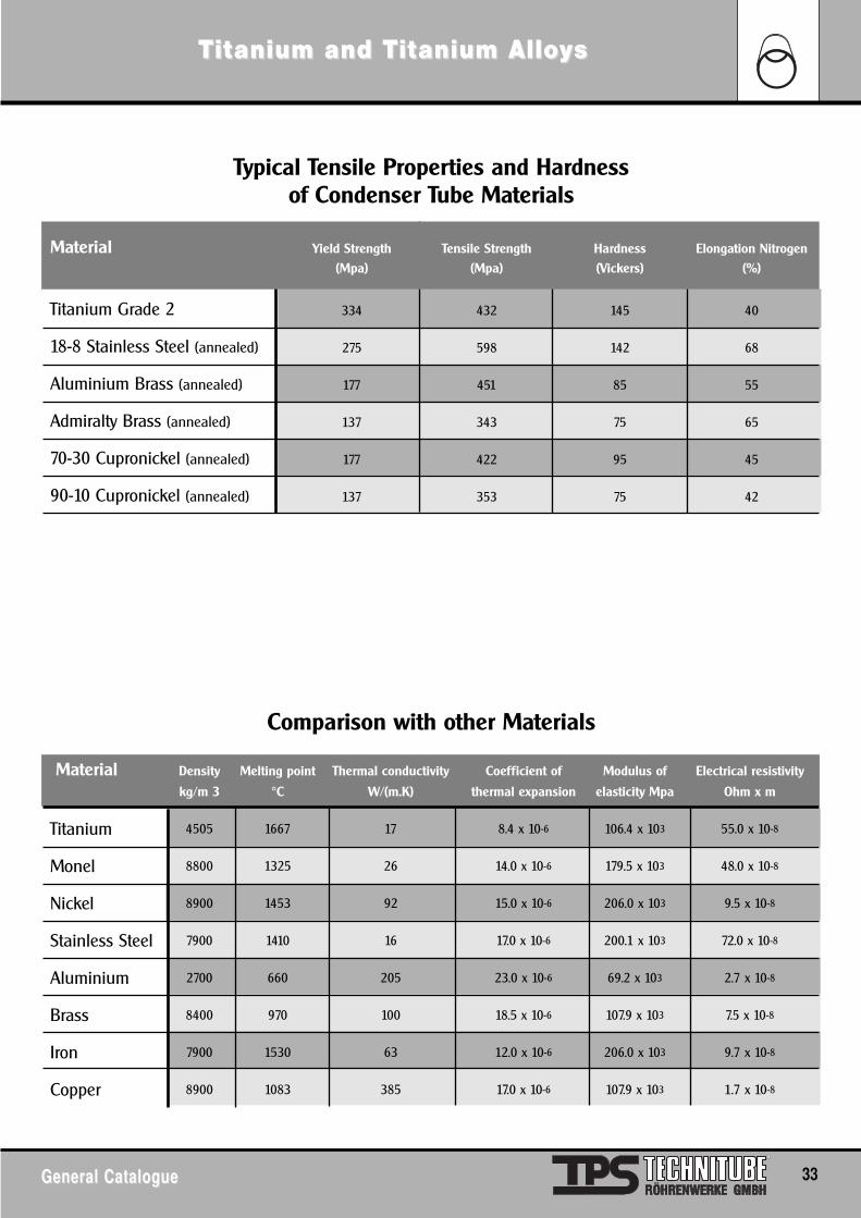
Typical Tensile Properties and Hardness of Condenser Tube Materials
Comparison with other Materials
Material Yield Strength Tensile Strength Hardness Elongation Nitrogen
(Mpa) (Mpa) (Vickers) (%)
Titanium Grade 2 334 432 145 40
18-8 Stainless Steel (annealed) 275 598 142 68
Aluminium Brass (annealed) 177 451 85 55
Admiralty Brass (annealed) 137 343 75 65
70-30 Cupronickel (annealed) 177 422 95 45
90-10 Cupronickel (annealed) 137 353 75 42
Material Density Melting point Thermal conductivity Coefficient of Modulus of Electrical resistivity
kg/m 3 °C W/(m.K) thermal expansion elasticity Mpa Ohm x m
Titanium 4505 1667 17 8.4 x 10⁻⁶ 106.4 x 10³ 55.0 x 10⁻⁸
Monel 8800 1325 26 14.0 x 10⁻⁶ 179.5 x 10³ 48.0 x 10⁻⁸
Nickel 8900 1453 92 15.0 x 10⁻⁶ 206.0 x 10³ 9.5 x 10⁻⁸
Stainless Steel 7900 1410 16 17.0 x 10⁻⁶ 200.1 x 10³ 72.0 x 10⁻⁸
Aluminium 2700 660 205 23.0 x 10⁻⁶ 69.2 x 10³ 2.7 x 10⁻⁸
Brass 8400 970 100 18.5 x 10⁻⁶ 107.9 x 10³ 7.5 x 10⁻⁸
Iron 7900 1530 63 12.0 x 10⁻⁶ 206.0 x 10³ 9.7 x 10⁻⁸
Copper 8900 1083 385 17.0 x 10⁻⁶ 107.9 x 10³ 1.7 x 10⁻⁸
TTititanium and Tanium and Tititanium Alloanium Alloyyss
34 General CatalogueGeneral Catalogue
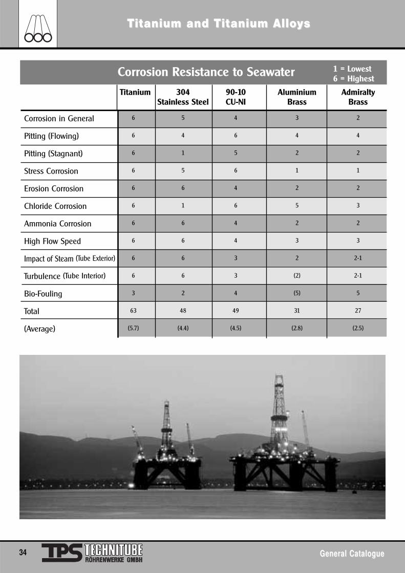
Titanium 304 90-10 Aluminium Admiralty Stainless Steel CU-NI Brass Brass
Corrosion in General 6 5 4 3 2
Pitting (Flowing) 6 4 6 4 4
Pitting (Stagnant) 6 1 5 2 2
Stress Corrosion 6 5 6 1 1
Erosion Corrosion 6 6 4 2 2
Chloride Corrosion 6 1 6 5 3
Ammonia Corrosion 6 6 4 2 2
High Flow Speed 6 6 4 3 3
Impact of Steam (Tube Exterior) 6 6 3 2 2-1
Turbulence (Tube Interior) 6 6 3 (2) 2-1
Bio-Fouling 3 2 4 (5) 5
Total 63 48 49 31 27
(Average) (5.7) (4.4) (4.5) (2.8) (2.5)
Corrosion Resistance to Seawater 1 = Lowest6 = Highest
TTititanium and Tanium and Tititanium Alloanium AlloyyssCORROSION RESISTANCE IN GENERAL
General CatalogueGeneral Catalogue 35
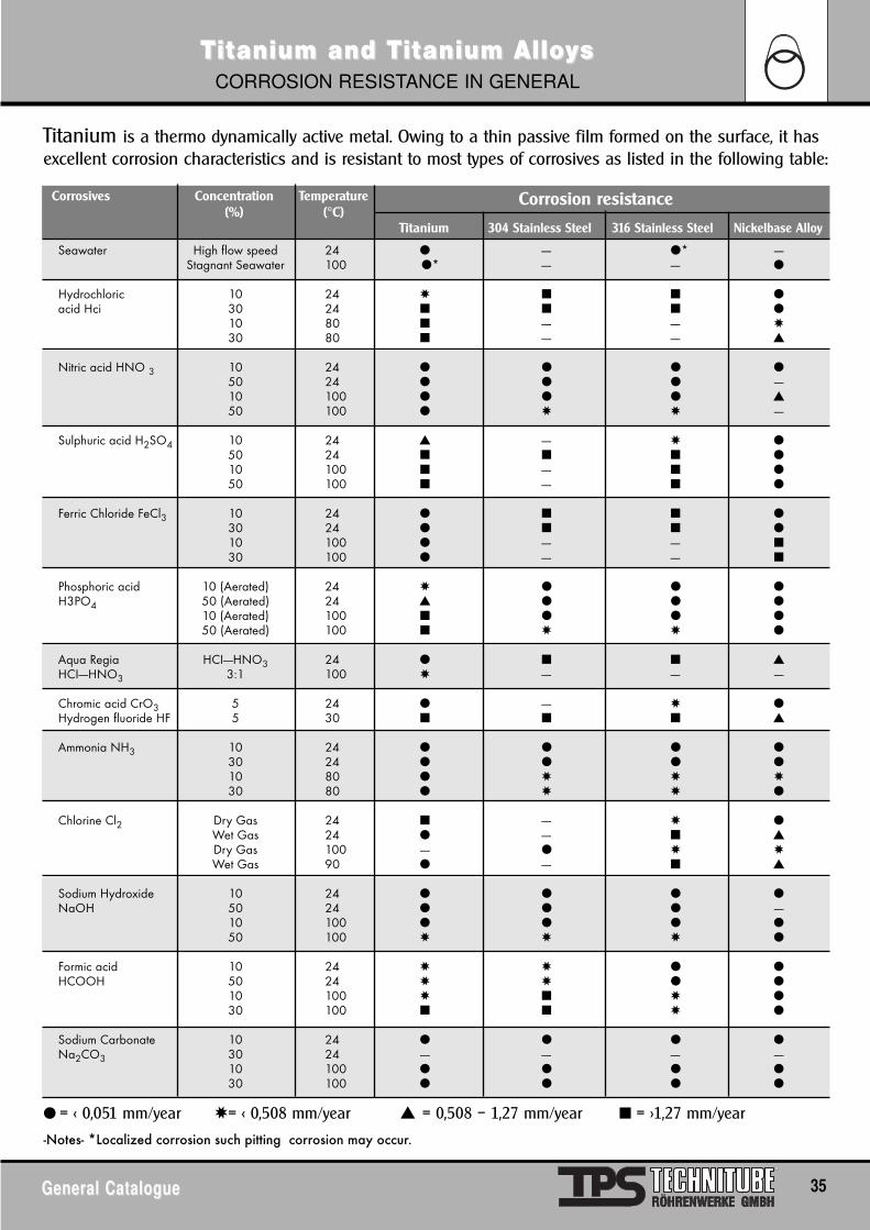
Titanium is a thermo dynamically active metal. Owing to a thin passive film formed on the surface, it has excellent corrosion characteristics and is resistant to most types of corrosives as listed in the following table:
Corrosives Concentration Temperature(%) (°C)
Titanium 304 Stainless Steel 316 Stainless Steel Nickelbase Alloy
Corrosion resistance
Seawater High flow speed 24 ● ---- ●* ----Stagnant Seawater 100 ●* ---- ---- ●
Hydrochloric 10 24 ✸ ■ ■ ●acid Hci 30 24 ■ ■ ■ ●
10 80 ■ ---- ---- ✸30 80 ■ ---- ---- ▲
Nitric acid HNO 3 10 24 ● ● ● ●50 24 ● ● ● ----10 100 ● ● ● ▲50 100 ● ✸ ✸ ----
Sulphuric acid H2SO4 10 24 ▲ ---- ✸ ●50 24 ■ ■ ■ ●10 100 ■ ---- ■ ●50 100 ■ ---- ■ ●
Ferric Chloride FeCl3 10 24 ● ■ ■ ●30 24 ● ■ ■ ●10 100 ● ---- ---- ■30 100 ● ---- ---- ■
Phosphoric acid 10 (Aerated) 24 ✸ ● ● ●H3PO4 50 (Aerated) 24 ▲ ● ● ●
10 (Aerated) 100 ■ ● ● ●50 (Aerated) 100 ■ ✸ ✸ ●
Aqua Regia HCI----HNO3 24 ● ■ ■ ▲HCI----HNO3 3:1 100 ✸ ---- ---- ----
Chromic acid CrO3 5 24 ● ---- ✸ ●Hydrogen fluoride HF 5 30 ■ ■ ■ ▲
Ammonia NH3 10 24 ● ● ● ●30 24 ● ● ● ●10 80 ● ✸ ✸ ✸30 80 ● ✸ ✸ ●
Chlorine Cl2 Dry Gas 24 ■ ---- ✸ ●Wet Gas 24 ● ---- ■ ▲Dry Gas 100 ---- ● ✸ ✸Wet Gas 90 ● ---- ■ ▲
Sodium Hydroxide 10 24 ● ● ● ●NaOH 50 24 ● ● ● ----
10 100 ● ● ● ●50 100 ✸ ✸ ✸ ●
Formic acid 10 24 ✸ ✸ ● ●HCOOH 50 24 ✸ ✸ ● ●
10 100 ✸ ■ ✸ ●30 100 ■ ■ ✸ ●
Sodium Carbonate 10 24 ● ● ● ●Na2CO3 30 24 ---- ---- ---- ----
10 100 ● ● ● ●30 100 ● ● ● ●
-Notes- *Localized corrosion such pitting corrosion may occur.
● = < 0,051 mm/year ✸= < 0,508 mm/year ▲ = 0,508 – 1,27 mm/year ■ = >1,27 mm/year
TTititanium and Tanium and Tititanium Alloanium AlloyyssCORROSION RESISTANCE IN GENERAL
36 General CatalogueGeneral Catalogue
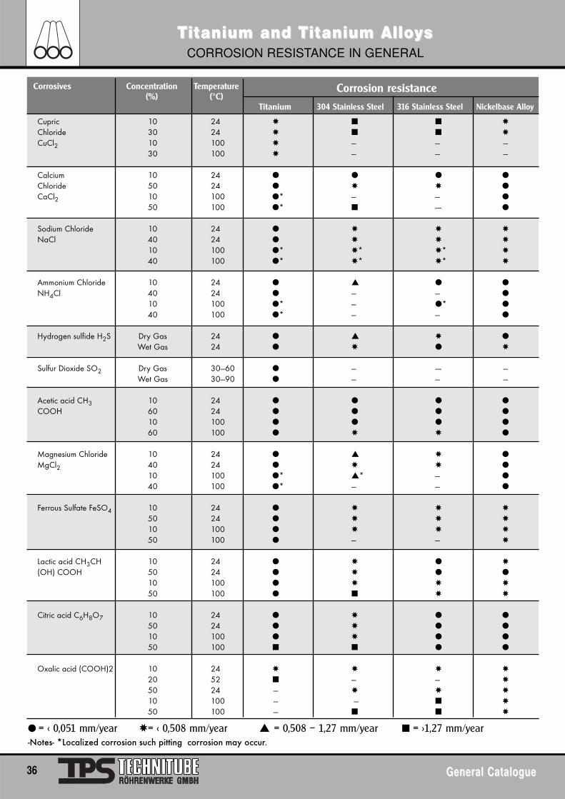
Corrosives Concentration Temperature(%) (°C)
Titanium 304 Stainless Steel 316 Stainless Steel Nickelbase Alloy
Cupric 10 24 ✸ ■ ■ ✸
Chloride 30 24 ✸ ■ ■ ✸
CuCl2 10 100 ✸ --- --- ---30 100 ✸ --- --- ---
Calcium 10 24 ● ● ● ●
Chloride 50 24 ● ✸ ✸ ●
CaCl2 10 100 ●* --- --- ●
50 100 ●* ■ ---- ●
Sodium Chloride 10 24 ● ✸ ✸ ✸
NaCl 40 24 ● ✸ ✸ ✸
10 100 ●* ✸* ✸* ✸
40 100 ●* ✸* ✸* ✸
Ammonium Chloride 10 24 ● ▲ ● ●
NH4Cl 40 24 ● --- --- ●
10 100 ●* --- ●* ●
40 100 ●* --- --- ●
Hydrogen sulfide H2S Dry Gas 24 ● ▲ ✸ ●
Wet Gas 24 ● ✸ ● ✸
Sulfur Dioxide SO2 Dry Gas 30---60 ● --- ---- ---Wet Gas 30---90 ● --- --- ---
Acetic acid CH3 10 24 ● ● ● ●
COOH 60 24 ● ● ● ●
10 100 ● ● ● ●
60 100 ● ✸ ✸ ●
Magnesium Chloride 10 24 ● ▲ ✸ ●
MgCl2 40 24 ● ✸ ✸ ●
10 100 ●* ▲* --- ●
40 100 ●* --- --- ●
Ferrous Sulfate FeSO4 10 24 ● ✸ ✸ ✸
50 24 ● ✸ ✸ ✸
10 100 ● ✸ ✸ ✸
50 100 ● --- --- ✸
Lactic acid CH3CH 10 24 ● ✸ ● ✸
(OH) COOH 50 24 ● ✸ ● ●
10 100 ● ✸ ✸ ✸
50 100 ● ■ ✸ ✸
Citric acid C6H8O7 10 24 ● ✸ ● ●
50 24 ● ✸ ● ●
10 100 ● ✸ ● ●
50 100 ■ ■ ● ●
Oxalic acid (COOH)2 10 24 ✸ ✸ ✸ ✸
20 52 ■ --- --- ✸
50 24 --- ✸ ✸ ✸
10 100 --- --- ■ ✸
50 100 --- ■ ■ ✸
Corrosion resistance
-Notes- *Localized corrosion such pitting corrosion may occur.● = < 0,051 mm/year ✸= < 0,508 mm/year ▲ = 0,508 – 1,27 mm/year ■ = >1,27 mm/year
General CatalogueGeneral Catalogue 37
SuperSuper -Duple-Duplex Sx Sttainless Sainless StteelseelsTUBING, PIPE, FLANGES, FITTINGS, ROUND BAR & PLATE
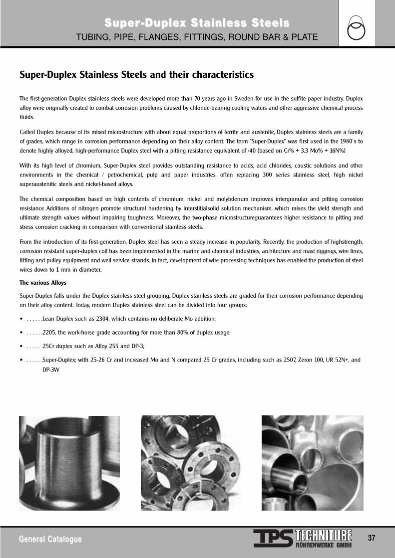
Super-Duplex Stainless Steels and their characteristics
The first-generation Duplex stainless steels were developed more than 70 years ago in Sweden for use in the sulfite paper industry. Duplex
alloy were originally created to combat corrosion problems caused by chloride-bearing cooling waters and other aggressive chemical process
fluids.
Called Duplex because of its mixed microstructure with about equal proportions of ferrite and austenite, Duplex stainless steels are a family
of grades, which range in corrosion performance depending on their alloy content. The term "Super-Duplex" was first used in the 1980`s to
denote highly alloyed, high-performance Duplex steel with a pitting resistance equivalent of >40 (based on Cr% + 3.3 Mo% + 16N%)
With its high level of chromium, Super-Duplex steel provides outstanding resistance to acids, acid chlorides, caustic solutions and other
environments in the chemical / petrochemical, pulp and paper industries, often replacing 300 series stainless steel, high nickel
superaustenitic steels and nickel-based alloys.
The chemical composition based on high contents of chromium, nickel and molybdenum improves intergranular and pitting corrosion
resistance Additions of nitrogen promote structural hardening by interstitialsolid solution mechanism, which raises the yield strength and
ultimate strength values without impairing toughness. Moreover, the two-phase microstructureguarantees higher resistance to pitting and
stress corrosion cracking in comparison with conventional stainless steels.
From the introduction of its first-generation, Duplex steel has seen a steady increase in popularity. Recently, the production of highstrength,
corrosion resistant super-duplex coil has been implemented in the marine and chemical industries, architecture and mast riggings, wire lines,
lifting and pulley equipment and well service strands. In fact, development of wire processing techniques has enabled the production of steel
wires down to 1 mm in diameter.
The various Alloys
Super-Duplex falls under the Duplex stainless steel grouping. Duplex stainless steels are graded for their corrosion performance depending
on their alloy content. Today, modern Duplex stainless steel can be divided into four groups:
• . . . . . .Lean Duplex such as 2304, which contains no deliberate Mo addition:
• . . . . . .2205, the work-horse grade accounting for more than 80% of duplex usage;
• . . . . . .25Cr duplex such as Alloy 255 and DP-3;
• . . . . . .Super-Duplex; with 25-26 Cr and increased Mo and N compared 25 Cr grades, including such as 2507, Zeron 100, UR 52N+, and
DP-3W
38 General CatalogueGeneral Catalogue
SuperSuper -Duple-Duplex Sx Sttainless Sainless StteelseelsTUBING, PIPE, FLANGES, FITTINGS, ROUND BAR & PLATE
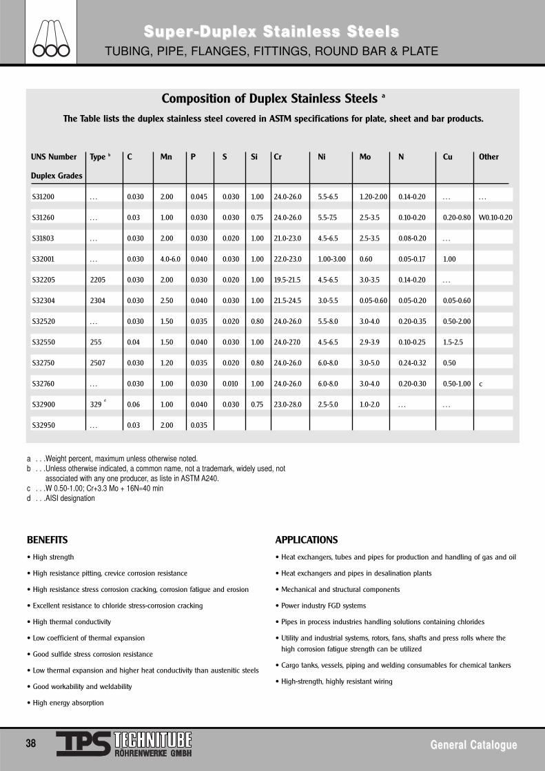
Composition of Duplex Stainless Steels a
The Table lists the duplex stainless steel covered in ASTM specifications for plate, sheet and bar products.
UNS Number Type b C Mn P S Si Cr Ni Mo N Cu Other
Duplex Grades
S31200 . . . 0.030 2.00 0.045 0.030 1.00 24.0-26.0 5.5-6.5 1.20-2.00 0.14-0.20 . . . . . .
S31260 . . . 0.03 1.00 0.030 0.030 0.75 24.0-26.0 5.5-7.5 2.5-3.5 0.10-0.20 0.20-0.80 W0.10-0.20
S31803 . . . 0.030 2.00 0.030 0.020 1.00 21.0-23.0 4.5-6.5 2.5-3.5 0.08-0.20 . . .
S32001 . . . 0.030 4.0-6.0 0.040 0.030 1.00 22.0-23.0 1.00-3.00 0.60 0.05-0.17 1.00
S32205 2205 0.030 2.00 0.030 0.020 1.00 19.5-21.5 4.5-6.5 3.0-3.5 0.14-0.20 . . .
S32304 2304 0.030 2.50 0.040 0.030 1.00 21.5-24.5 3.0-5.5 0.05-0.60 0.05-0.20 0.05-0.60
S32520 . . . 0.030 1.50 0.035 0.020 0.80 24.0-26.0 5.5-8.0 3.0-4.0 0.20-0.35 0.50-2.00
S32550 255 0.04 1.50 0.040 0.030 1.00 24.0-27.0 4.5-6.5 2.9-3.9 0.10-0.25 1.5-2.5
S32750 2507 0.030 1.20 0.035 0.020 0.80 24.0-26.0 6.0-8.0 3.0-5.0 0.24-0.32 0.50
S32760 . . . 0.030 1.00 0.030 0.010 1.00 24.0-26.0 6.0-8.0 3.0-4.0 0.20-0.30 0.50-1.00 c
S32900 329 d
0.06 1.00 0.040 0.030 0.75 23.0-28.0 2.5-5.0 1.0-2.0 . . . . . .
S32950 . . . 0.03 2.00 0.035
a . . .Weight percent, maximum unless otherwise noted.b . . .Unless otherwise indicated, a common name, not a trademark, widely used, not
associated with any one producer, as liste in ASTM A240.c . . .W 0.50-1.00; Cr+3.3 Mo + 16N=40 mind . . .AISI designation
BENEFITS
• High strength
• High resistance pitting, crevice corrosion resistance
• High resistance stress corrosion cracking, corrosion fatigue and erosion
• Excellent resistance to chloride stress-corrosion cracking
• High thermal conductivity
• Low coefficient of thermal expansion
• Good sulfide stress corrosion resistance
• Low thermal expansion and higher heat conductivity than austenitic steels
• Good workability and weldability
• High energy absorption
APPLICATIONS
• Heat exchangers, tubes and pipes for production and handling of gas and oil
• Heat exchangers and pipes in desalination plants
• Mechanical and structural components
• Power industry FGD systems
• Pipes in process industries handling solutions containing chlorides
• Utility and industrial systems, rotors, fans, shafts and press rolls where thehigh corrosion fatigue strength can be utilized
• Cargo tanks, vessels, piping and welding consumables for chemical tankers
• High-strength, highly resistant wiring
General CatalogueGeneral Catalogue 39
Special SSpecial Sttainless Sainless StteelseelsFOR THE UREA/FERTILIZER INDUSTRY • MATERIAL NO. 1.4429
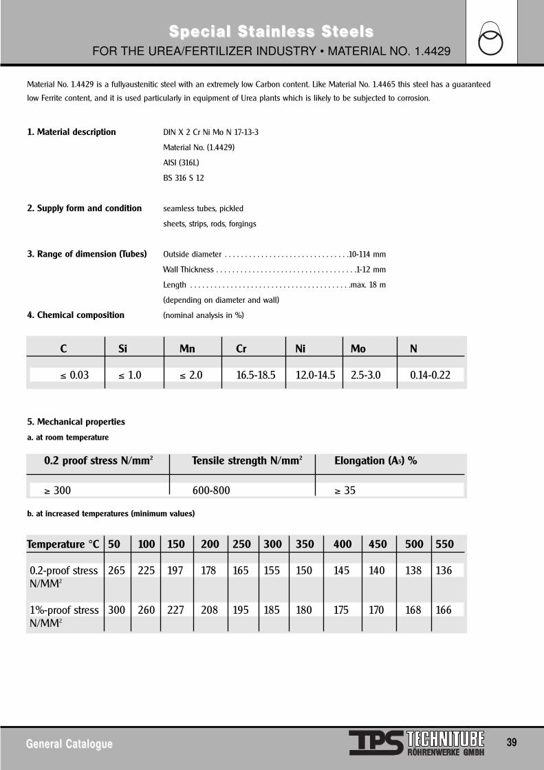
Material No. 1.4429 is a fullyaustenitic steel with an extremely low Carbon content. Like Material No. 1.4465 this steel has a guaranteed
low Ferrite content, and it is used particularly in equipment of Urea plants which is likely to be subjected to corrosion.
1. Material description DIN X 2 Cr Ni Mo N 17-13-3
Material No. (1.4429)
AISI (316L)
BS 316 S 12
2. Supply form and condition seamless tubes, pickled
sheets, strips, rods, forgings
3. Range of dimension (Tubes) Outside diameter . . . . . . . . . . . . . . . . . . . . . . . . . . . . . . .10-114 mm
Wall Thickness . . . . . . . . . . . . . . . . . . . . . . . . . . . . . . . . . . .1-12 mm
Length . . . . . . . . . . . . . . . . . . . . . . . . . . . . . . . . . . . . . . . .max. 18 m
(depending on diameter and wall)
4. Chemical composition (nominal analysis in %)
5. Mechanical properties
a. at room temperature
b. at increased temperatures (minimum values)
C Si Mn Cr Ni Mo N
≤ 0.03 ≤ 1.0 ≤ 2.0 16.5-18.5 12.0-14.5 2.5-3.0 0.14-0.22
0.2 proof stress N/mm2 Tensile strength N/mm2 Elongation (A5) %
≥ 300 600-800 ≥ 35
Temperature °C 50 100 150 200 250 300 350 400 450 500 550
0.2-proof stress 265 225 197 178 165 155 150 145 140 138 136N/MM2
1%-proof stress 300 260 227 208 195 185 180 175 170 168 166N/MM2
40 General CatalogueGeneral Catalogue
Special SSpecial Sttainless Sainless StteelseelsFOR THE UREA/FERTILIZER INDUSTRY • MATERIAL NO. 1.4429
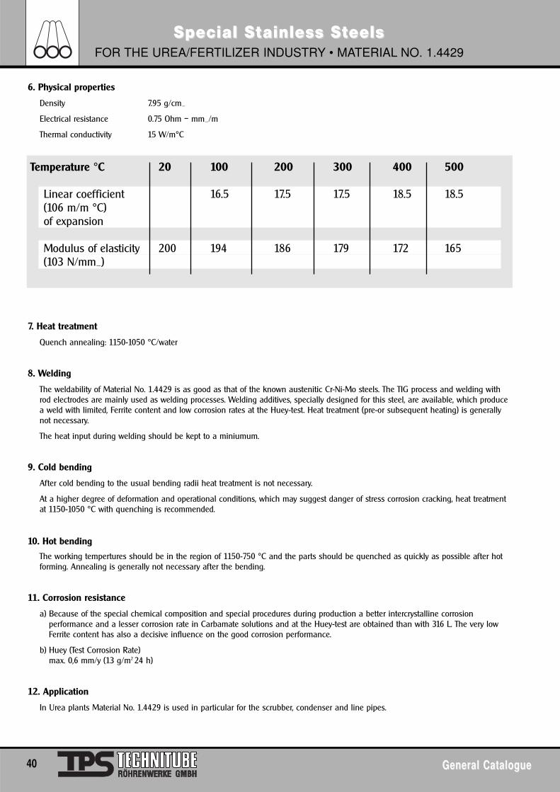
6. Physical properties
Density 7.95 g/cm_
Electrical resistance 0.75 Ohm – mm_/m
Thermal conductivity 15 W/m°C
7. Heat treatment
Quench annealing: 1150-1050 °C/water
8. Welding
The weldability of Material No. 1.4429 is as good as that of the known austenitic Cr-Ni-Mo steels. The TIG process and welding withrod electrodes are mainly used as welding processes. Welding additives, specially designed for this steel, are available, which producea weld with limited, Ferrite content and low corrosion rates at the Huey-test. Heat treatment (pre-or subsequent heating) is generallynot necessary.
The heat input during welding should be kept to a miniumum.
9. Cold bending
After cold bending to the usual bending radii heat treatment is not necessary.
At a higher degree of deformation and operational conditions, which may suggest danger of stress corrosion cracking, heat treatmentat 1150-1050 °C with quenching is recommended.
10. Hot bending
The working tempertures should be in the region of 1150-750 °C and the parts should be quenched as quickly as possible after hotforming. Annealing is generally not necessary after the bending.
11. Corrosion resistance
a) Because of the special chemical composition and special procedures during production a better intercrystalline corrosionperformance and a lesser corrosion rate in Carbamate solutions and at the Huey-test are obtained than with 316 L. The very lowFerrite content has also a decisive influence on the good corrosion performance.
b) Huey (Test Corrosion Rate)max. 0,6 mm/y (13 g/m2 24 h)
12. Application
In Urea plants Material No. 1.4429 is used in particular for the scrubber, condenser and line pipes.
Temperature °C 20 100 200 300 400 500
Linear coefficient 16.5 17.5 17.5 18.5 18.5(106 m/m °C)of expansion
Modulus of elasticity 200 194 186 179 172 165(103 N/mm_)
General CatalogueGeneral Catalogue 41
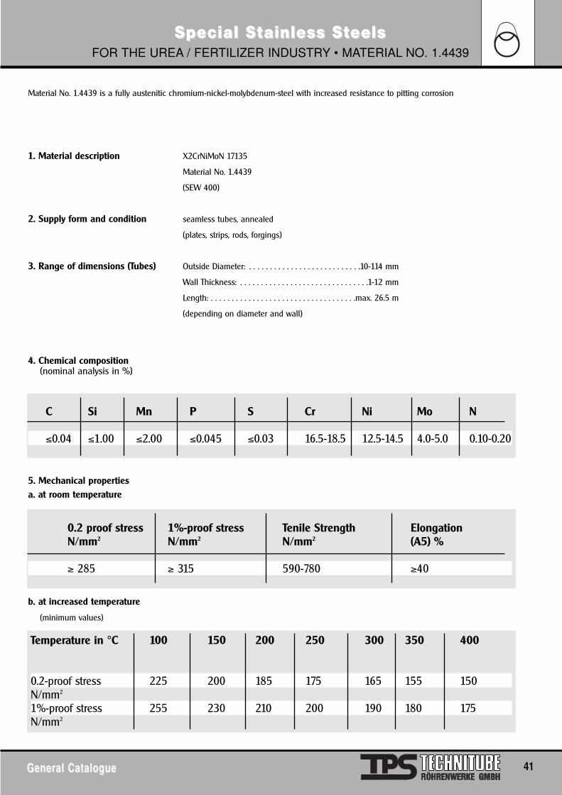
Special SSpecial Sttainless Sainless StteelseelsFOR THE UREA / FERTILIZER INDUSTRY • MATERIAL NO. 1.4439
Material No. 1.4439 is a fully austenitic chromium-nickel-molybdenum-steel with increased resistance to pitting corrosion
1. Material description X2CrNiMoN 17135
Material No. 1.4439
(SEW 400)
2. Supply form and condition seamless tubes, annealed
(plates, strips, rods, forgings)
3. Range of dimensions (Tubes) Outside Diameter: . . . . . . . . . . . . . . . . . . . . . . . . . . .10-114 mm
Wall Thickness: . . . . . . . . . . . . . . . . . . . . . . . . . . . . . . .1-12 mm
Length: . . . . . . . . . . . . . . . . . . . . . . . . . . . . . . . . . . .max. 26.5 m
(depending on diameter and wall)
4. Chemical composition (nominal analysis in %)
5. Mechanical propertiesa. at room temperature
b. at increased temperature
(minimum values)
C Si Mn P S Cr Ni Mo N
≤0.04 ≤1.00 ≤2.00 ≤0.045 ≤0.03 16.5-18.5 12.5-14.5 4.0-5.0 0.10-0.20
0.2 proof stress 1%-proof stress Tenile Strength ElongationN/mm2 N/mm2 N/mm2 (A5) %
≥ 285 ≥ 315 590-780 ≥40
Temperature in °C 100 150 200 250 300 350 400
0.2-proof stress 225 200 185 175 165 155 150N/mm2
1%-proof stress 255 230 210 200 190 180 175N/mm2
42 General CatalogueGeneral Catalogue
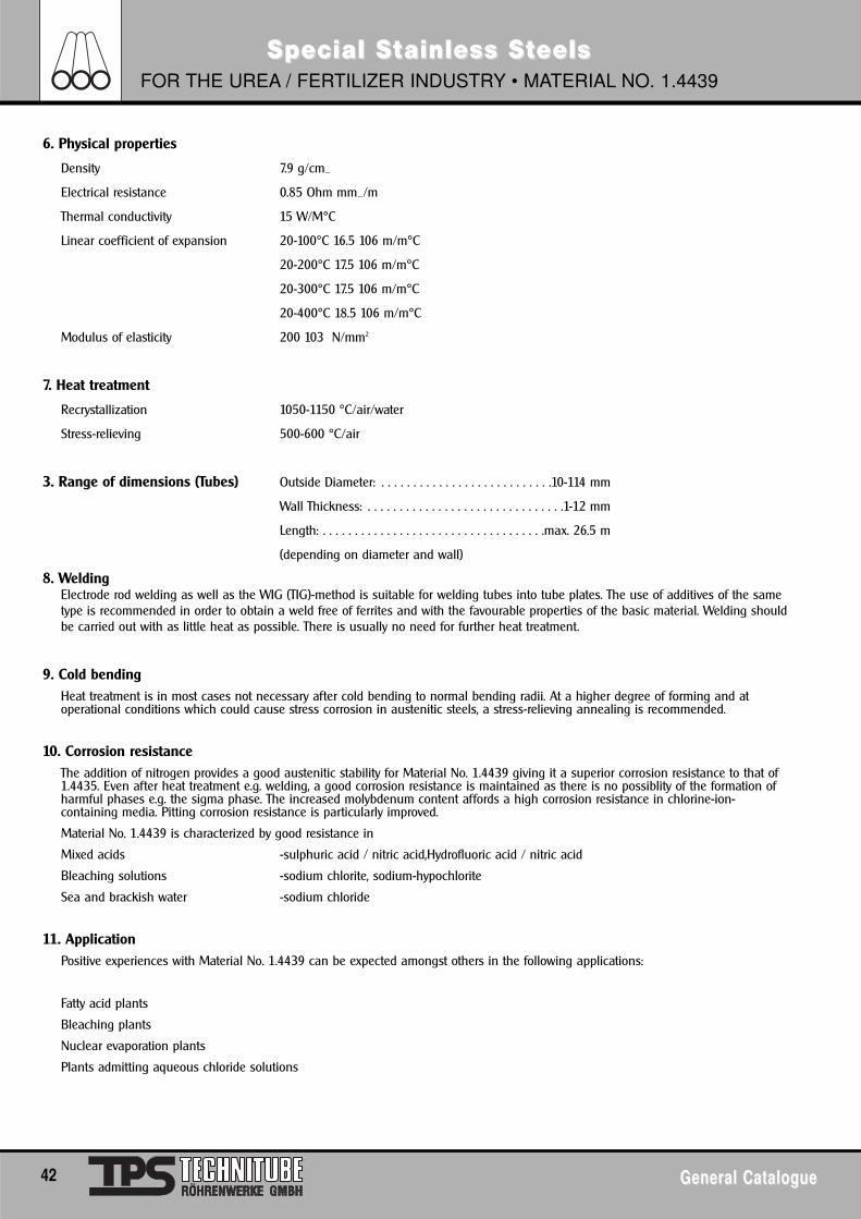
Special SSpecial Sttainless Sainless StteelseelsFOR THE UREA / FERTILIZER INDUSTRY • MATERIAL NO. 1.4439
6. Physical properties
Density 7.9 g/cm_
Electrical resistance 0.85 Ohm mm_/m
Thermal conductivity 15 W/M°C
Linear coefficient of expansion 20-100°C 16.5 106 m/m°C
20-200°C 17.5 106 m/m°C
20-300°C 17.5 106 m/m°C
20-400°C 18.5 106 m/m°C
Modulus of elasticity 200 103 N/mm2
7. Heat treatment
Recrystallization 1050-1150 °C/air/water
Stress-relieving 500-600 °C/air
3. Range of dimensions (Tubes) Outside Diameter: . . . . . . . . . . . . . . . . . . . . . . . . . . .10-114 mm
Wall Thickness: . . . . . . . . . . . . . . . . . . . . . . . . . . . . . . .1-12 mm
Length: . . . . . . . . . . . . . . . . . . . . . . . . . . . . . . . . . . .max. 26.5 m
(depending on diameter and wall)
8. WeldingElectrode rod welding as well as the WIG (TIG)-method is suitable for welding tubes into tube plates. The use of additives of the sametype is recommended in order to obtain a weld free of ferrites and with the favourable properties of the basic material. Welding shouldbe carried out with as little heat as possible. There is usually no need for further heat treatment.
9. Cold bendingHeat treatment is in most cases not necessary after cold bending to normal bending radii. At a higher degree of forming and atoperational conditions which could cause stress corrosion in austenitic steels, a stress-relieving annealing is recommended.
10. Corrosion resistanceThe addition of nitrogen provides a good austenitic stability for Material No. 1.4439 giving it a superior corrosion resistance to that of1.4435. Even after heat treatment e.g. welding, a good corrosion resistance is maintained as there is no possiblity of the formation ofharmful phases e.g. the sigma phase. The increased molybdenum content affords a high corrosion resistance in chlorine-ion-containing media. Pitting corrosion resistance is particularly improved.
Material No. 1.4439 is characterized by good resistance in
Mixed acids -sulphuric acid / nitric acid,Hydrofluoric acid / nitric acid
Bleaching solutions -sodium chlorite, sodium-hypochlorite
Sea and brackish water -sodium chloride
11. ApplicationPositive experiences with Material No. 1.4439 can be expected amongst others in the following applications:
Fatty acid plants
Bleaching plants
Nuclear evaporation plants
Plants admitting aqueous chloride solutions
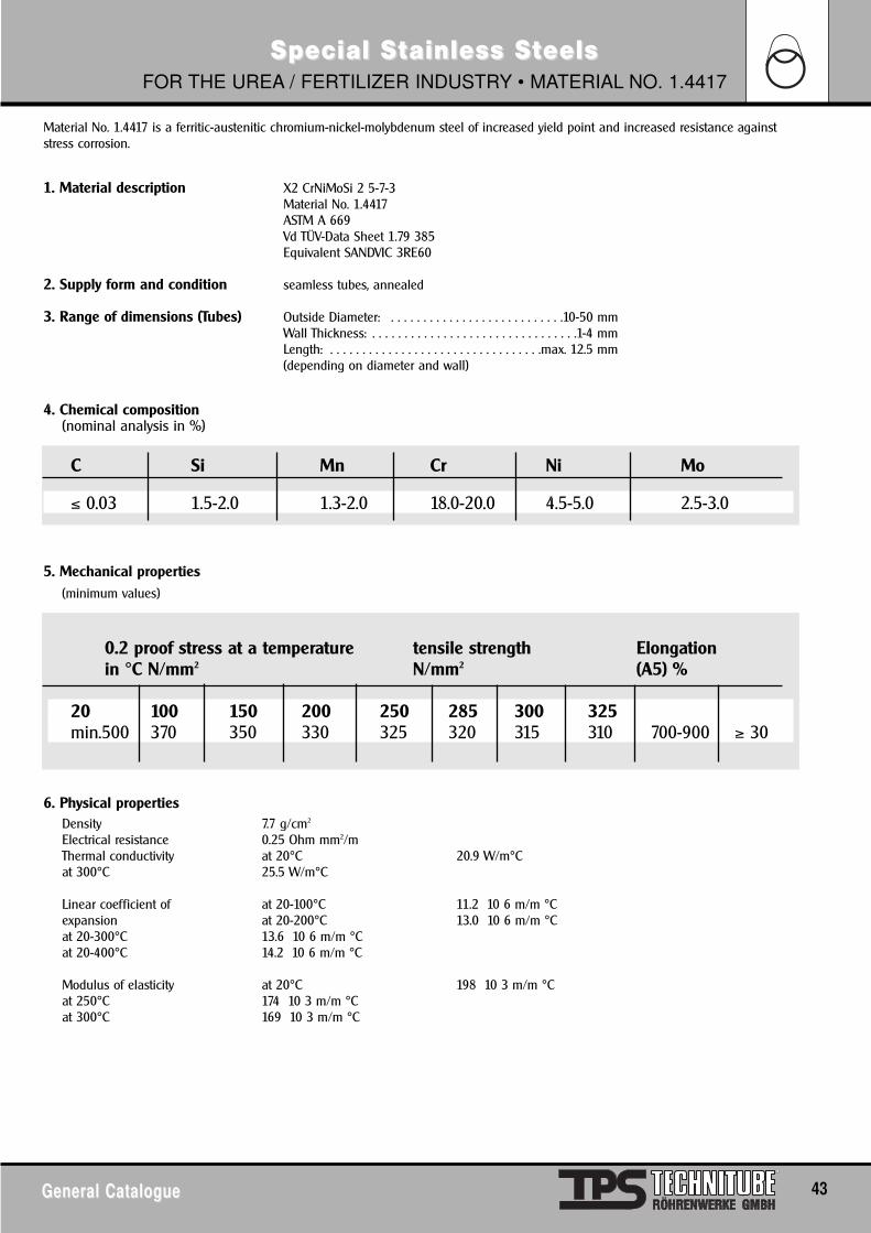
General CatalogueGeneral Catalogue 43
Special SSpecial Sttainless Sainless StteelseelsFOR THE UREA / FERTILIZER INDUSTRY • MATERIAL NO. 1.4417
Material No. 1.4417 is a ferritic-austenitic chromium-nickel-molybdenum steel of increased yield point and increased resistance againststress corrosion.
1. Material description X2 CrNiMoSi 2 5-7-3Material No. 1.4417ASTM A 669Vd TÜV-Data Sheet 1.79 385Equivalent SANDVIC 3RE60
2. Supply form and condition seamless tubes, annealed
3. Range of dimensions (Tubes) Outside Diameter: . . . . . . . . . . . . . . . . . . . . . . . . . . .10-50 mmWall Thickness: . . . . . . . . . . . . . . . . . . . . . . . . . . . . . . . .1-4 mmLength: . . . . . . . . . . . . . . . . . . . . . . . . . . . . . . . . .max. 12.5 mm(depending on diameter and wall)
4. Chemical composition (nominal analysis in %)
5. Mechanical properties(minimum values)
6. Physical propertiesDensity 7.7 g/cm2
Electrical resistance 0.25 Ohm mm2/mThermal conductivity at 20°C 20.9 W/m°Cat 300°C 25.5 W/m°C
Linear coefficient of at 20-100°C 11.2 10 6 m/m °Cexpansion at 20-200°C 13.0 10 6 m/m °Cat 20-300°C 13.6 10 6 m/m °Cat 20-400°C 14.2 10 6 m/m °C
Modulus of elasticity at 20°C 198 10 3 m/m °Cat 250°C 174 10 3 m/m °Cat 300°C 169 10 3 m/m °C
C Si Mn Cr Ni Mo
≤ 0.03 1.5-2.0 1.3-2.0 18.0-20.0 4.5-5.0 2.5-3.0
0.2 proof stress at a temperature tensile strength Elongationin °C N/mm2 N/mm2 (A5) %
20 100 150 200 250 285 300 325min.500 370 350 330 325 320 315 310 700-900 ≥ 30
44 General CatalogueGeneral Catalogue
Special SSpecial Sttainless Sainless StteelseelsFOR THE UREA / FERTILIZER INDUSTRY • MATERIAL NO. 1.4417
7. Heat treatment
Quench annealing 950-1050°C/air or water
3. Range of dimensions (Tubes) Outside Diameter: 10-114 mmWall Thickness: 1-12 mmLength: max. 26.5 m(depending on diameter and wall)
8. Welding
Weldability of Material No. 1.4417 is good. Due to the danger of carburizing, gas fusion welding should be avoided. For wall thicknessfrom 0.8 mm up TIG-welding is recommended; from 1.5 mm up especially in case of fillet welds-arc welding with sheated barelectrodes is possible. After welding no heat treatment is required.
For the design of heat exchangers, tubes of Material No. 1.4417 are normally connected with tube sheets of fully austenitic steel orboiler construction steel. For these cases the following welding filler metals may be recommended:
a. to austenitic steel, e.g. (1.4571
Nominal analysis20% Cr 67 % Ni 3 % Fe19% Cr 10 % Ni 2.5 % Mo19% Cr 11.5 % Ni 2.8 % Mo
b. to low-alloyed steel, e.g. boiler plate 17Mn4Nominal analysis24 % Cr 13 % Ni20 % Cr 67 % Ni 3 % Fe18 % Cr 8 % Ni 6 % Mn
The welding filler metals mentioned under a. and b. have a C-content of max. 0.03% with the exception of alloy-type 18/8/6 having aC-content of approx 0.10%. If high stress of the welding joints has to be taken into account, welding filler metals of LC-quality shouldbe used. In case of using Mo-free filler metal, the corrosion characteristics of the weld metal have to be taken into account.
9. Cold bendingGenerally, in case of usual bending radii, post heating will not be required. In case of a higher degree of deformation at lowtemperatures ( > 10% ) annealing as indicated under 7. is necessary.
10. Hot bendingHot bending should be performed in the temperature range from 1100-900°C. Afterwards, quench annealing as described under 7. willhave to be carried out.
11. Corrosion behaviourDue to its two-phase structure, Material No. 1.4417 has a higher resistivity against stress corrosion cracking than comparable fullyaustenitic CrNi-steels. Its use in media containing chloride, e.g. brackish water, is to be recommended, when austenitic steels havefailed because of stress corrosion cracking. Its resistance against pitting is similar to that of X2CrNiMo 1812. In non-oxidizing solutions,e.g. formic acid and oxalic acid, a good continuity is noted.
12. ApplicationDue to its favourable physical-technological and corrosion-chemical characteristics, Material No. 1.4417 is preferably used in thefollowing fields:
High pressure processes of the chemical industryDue to its increased yield point there are advantages regarding wall thickness design.
13. ApplicationApplication over long periods exceeding 325°C should be avoided. For pressure vessels according to AD-W2 the service temperatureshould range between-10°C up to + 285°C(VdTÜV-Data Sheet)
General CatalogueGeneral Catalogue 45
Special SSpecial Sttainless Sainless StteelseelsFOR THE UREA / FERTILIZER INDUSTRY • MATERIAL NO. 1.4465
Material No. 1.4465 is a fully austenitic Chromium-Nickel-Molybdenum steel with an extremely low Carbon content. The material isdistinguished by very low corrosion rates at the Huey-test, and it is applied especially in those parts of Urea plants which are subjected tothe most corrosive conditions.
1. Material description X2CrNiMoN 25-25-2Material No. (1.4465)
2. Supply form and condition seamless tubes, pickled(sheets, strips, rods, forgings)
3. Range of dimensions (Tubes) Outside Diameter: . . . . . . . . . . . . . . . . . . . . . . . . . . .10-114 mmWall thickness: . . . . . . . . . . . . . . . . . . . . . . . . . . . . . . .1-12 mmLength: . . . . . . . . . . . . . . . . . . . . . . . . . . . . . . . . . . .max. 26.5 m(depending on diameter and wall)
4. Chemical composition (nominal analysis in %)
5. Mechanical properties
a) at room temperature
b) at increased temperature(minimum values)
C Si Mn Cr Ni Mo N
≤ 0.020 ≤ 0.40 1.5-2.0 24.5-25.5 21.5-22.5 1.9-2.3 0.10-0.14
0,2% proof stress Tensile strength ElongationN/mm2 N/mm2 (A5)
min. 255 min. 540 > 30
Temperature °C 100 200 300 400 500
0,2-proof stress 230 210 185 160 140N/mm2
1%-proof stress 270 240 220 195 170N/mm2
46 General CatalogueGeneral Catalogue
Special SSpecial Sttainless Sainless StteelseelsFOR THE UREA / FERTILIZER INDUSTRY • MATERIAL NO. 1.4465
6. Physical propertiesDensity 7,9 g/cm2
Spec. electrical resistance 0,90 Ohm mm2/mThermal conductivity 15 W/m °C
7. Heat treatmentQuench annealing: 1050-1150 °C/water
Bright annealed: 1050-1150 ° C/gas
8. Welding
The weldability of Material No. 1.4465 can be described as good. For welding into tube sheets welding rods as well as the TIG weldingprocess can be used.
As welding additives we recommend for the above processes S-NiCrFe27MoCu Material No. 1.4455, depending on application. Heattreatment (pre-or subsequent heating, resp) is generally not required.
As usual with austenitic Cr-Ni-steels, Material No. 1.4465 must also be welded with the least possible heat input.
9. Cold bending
There is generally no need for heat treatment after cold bending to usual bending radii. At a higher degree of deformation andoperational conditions, which may suggest danger of stress corrosion cracking, heat treatment at 1050-1150 °C is recommended.
10. Hot bending
Hot bending should be carried out at a temperature range of 1150-850 °C. A quenching after hot forming can be advisable in somecases for maintaining the optimum corrosion performance. At rapid quenching from the hot forming temperature a subsequentannealing is generally not necessary.
11. Corrosion resistance
Material No. 1.4465 is distinguished from similar alloy steels not only by a better performance is respect of the corrosion rate, but alsoby higher resistance when subjected to pitting, stress corrosion cracking and inter-crystalline corrosion.
a. Intercrystalline corrosion
The excellent resistance to inter crystalline corrosion is proved by the Strauss-test
(SEP 1875-61 / DIN 50914) as well as the Huey-test (ASTM A 262, Practice C.)
Temperature °C 20 100 200 300 400 500
Linerar coefficient 15,0 15,7 16,0 16,6 16,8(10 6 m/m °C)of expansion
Modulus of elasticity 200 195 180 178 170 164(10 3 N/mm2)
General CatalogueGeneral Catalogue 47
Special SSpecial Sttainless Sainless StteelseelsFOR THE UREA / FERTILIZER INDUSTRY • MATERIAL NO. 1.4465
b.Huey-testApart from the testing for resistance to grain disintegration the Huey-test also serves for investigating whether there are any furtherinhomogeneities such as precipitations within the grain, sigma phase and inclusions of Ferrite. For this reason the Huey-test representsa very strict testing method, which includes a great number of parameters.
Material No. 1.4465 has a max. corrosion rate of 1,5 µm/48h=
5,91 g/m2 24h=0.27 mm/year at the Huey-test. This extraordinarily low value can only be guaranteed by special provisions at theproduction of the steel and by extensive quality control during the various of production.
c.Pitting corrosionDue to the Molybdenum content and the increased Chromium content there is a good corrosion resistance to flowing waterscontaining Chlorides.
d.Stress corrosion crackingDue to the increased Nickel content, Material No. 1.4465 has a considerably higher range of resistance to stress corrosion crackingthan e.g. X2CrNiMo 1812 (TP 316 L)
e.Special environmentsMaterial No. 1.4465 offers excellent corrosion resistance to a great number of corrosion environments. Especially worth noting here isthe good performance in Nitric acid, Phosphoric acid and the Ammonium carbamate solution occurring in the Urea process.
12. Application
Urea plantsMaterial No. 1.4465 has been developed for the especially high requirements in strippers of Urea plants to the Stamicarbon processroute.
This steel can also be successfully used, however, for other processes, where similar operational conditions exist as in the strippingprocess.
Nitric acid plantsDue to the very small corrosion rates at the Huey-test, Material No. 1.4465 is suitable for the application in Nitric acid plants and inequipment that is subjected to Nitric acid.
Other plantsBecause of the increased corrosion performance as against comperable steels such as
X3CrNiMoN 2525, X2CrNiMo 1810 and X2CrNi 189 the application of Material No. 1.4465 should be also considered, if the formersteels have failed to produce satisfactory results.
48 General CatalogueGeneral Catalogue
Special SSpecial Sttainless Sainless Stteel Ueel Urrea Tea TubesubesAISI 316 L (1.4435) / 1.4466 MATERIAL DATA
Material Data 1.4435 X 2 CrNiMo 18-14-3 W. No. 1.4435AISI TYPE 316 LStamicarbon nv: Spez. 18005 Section I Material
Chemical composition in wt.%
Mechanical properties at 20°C
Mechanical properties at elevated temperatures in N/mm2
Characteristics:Material No. 1.4466 and Mat. No. 1.4435 are austenitic, stainless and acidresisting nickel, chromium, molybdenum steels with a very low carboncontent (ELC type).
Both grades have a fully austenitic structure. Material No. 1.4466 featuresimproved strength due to its nitrogen addition, which is of particularimportance for the 0,2% proof stress to be used as design basis. Material No.1.4435 was mainly developed for urea plant applications.
Applications:Material No. 1.4466 and Material No. 1.4435 are mainly used for parts andequipment in urea plant subjected to high pressures and temperatures, andto severe corrosion (steam separator, condenser, reactor, stripper, scrubber).Both grades are also suitable for applications involving the attack of a varietyof chemicals in dyemills, in the textile, paper and leather industries, as wellas the chemical, pharmaceutical and plastics industries.
The steels are not magnetic.
Corrosion resistance Intergranular corrosionOwing to their alloying elements and to the melting technique employed.
Material No. 1.4466 and 1.4435 feature very good resistance to intergranular
corrosion when tested according to DIN 50914. Their corrosion resistance isalso found to be excellent when subjected to a Huey test according to ASTMA 252 Practice C – a maximum corrosion rate of 0.247 g/m_hr (1.4466) and0.54 g/m_hr (1.4435) obtained as an average of 5 bolling periods of 48hours each can be guaranteed.
Stress corrosion cracking and pittingThe alloying elements of Material No. 1.4466 give this grade improvedresistance to stress corrosion cracking and pitting in high-chloride media(e.g. sea water) compared to that of conventional 18/8 steels.
Forming propertiesBoth grades can conveniently be cold formed, hot formed and machined.
Welding propertiesWelding presents no difficulties. With an approved welding technique forfully austenitic filler metals sound weld joints can be achieved up to a platethickness of 80 mm. Welding should be carried out with a short arc andmean amperage taking care to prevent weave beads exeeding two times theelectrode diameter. Thick layers are to be avoided. It is recommended to chipout the end craters. Interpass temperature should not exceed 150°. Quite ongeneral, no postheat-treatment is required.
C Si Mn P S Cr Mo Ni
max.0,020 0,50 1,70 max.0,015 max.0,010 17,5 2,5 14,5
0,2% proof stress 1% proof stress tensile strength elongation afterN/mm2 min. N/mm2 N/mm2 fracture (Lo=5do)
min.
195 235 450-700 40
Temperature °C 100 150 200 250 300 350 400 450 5000,2% proof stress 165 150 137 127 119 113 108 103 1001% proof stress 200 180 165 153 145 139 135 130 128
Physical propertiesSpecific gravity at 20°C . . . . . . . . . . .7,95 g/cm2Thermal conductivity at 20°C . . . . . .15 W/mKSpecific heat at 20°C . . . . . . . . . . . . .500 J/kgKModulus of elasticity at 20°C . . . . . .200000 N/mm2
Thermal expansion in 10-6 m/m °C . . . . . . .20 to 100°C 16,5 . . . . . . . . . . . . . . . . . . . . . . . . . . . . . . . . .20 to 200°C 17,5 . . . . . . . . . . . . . . . . . . . . . . . . . . . . . . . . .20 to 300°C 17,5 . . . . . . . . . . . . . . . . . . . . . . . . . . . . . . . . .20 to 400°C 18,5 . . . . . . . . . . . . . . . . . . . . . . . . . . . . . . . . .20 to 500°C 18,5
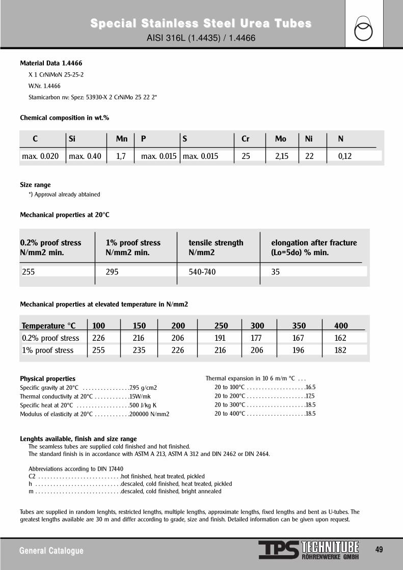
General CatalogueGeneral Catalogue 49
Material Data 1.4466
X 1 CrNiMoN 25-25-2
W.Nr. 1.4466
Stamicarbon nv: Spez: 53930-X 2 CrNiMo 25 22 2*
Chemical composition in wt.%
Size range*) Approval already abtained
Mechanical properties at 20°C
Mechanical properties at elevated temperature in N/mm2
Lenghts available, finish and size rangeThe seamless tubes are supplied cold finished and hot finished.The standard finish is in accordance with ASTM A 213, ASTM A 312 and DIN 2462 or DIN 2464.
Abbreviations according to DIN 17440C2 . . . . . . . . . . . . . . . . . . . . . . . . . . . .hot finished, heat treated, pickledh . . . . . . . . . . . . . . . . . . . . . . . . . . . . .descaled, cold finished, heat treated, pickledm . . . . . . . . . . . . . . . . . . . . . . . . . . . . .descaled, cold finished, bright annealed
Tubes are supplied in random lenghts, restricted lengths, multiple lengths, approximate lengths, fixed lengths and bent as U-tubes. Thegreatest lengths available are 30 m and differ according to grade, size and finish. Detailed information can be given upon request.
C Si Mn P S Cr Mo Ni N
max. 0.020 max. 0.40 1,7 max. 0.015 max. 0.015 25 2,15 22 0,12
Special SSpecial Sttainless Sainless Stteel Ueel Urrea Tea TubesubesAISI 316L (1.4435) / 1.4466
0.2% proof stress 1% proof stress tensile strength elongation after fractureN/mm2 min. N/mm2 min. N/mm2 (Lo=5do) % min.
255 295 540-740 35
Temperature °C 100 150 200 250 300 350 4000.2% proof stress 226 216 206 191 177 167 1621% proof stress 255 235 226 216 206 196 182
Physical propertiesSpecific gravity at 20°C . . . . . . . . . . . . . . . .7.95 g/cm2Thermal conductivity at 20°C . . . . . . . . . . . .15W/mkSpecific heat at 20°C . . . . . . . . . . . . . . . . . .500 J/kg KModulus of elasticity at 20°C . . . . . . . . . . . .200000 N/mm2
Thermal expansion in 10 6 m/m °C . . .20 to 100°C . . . . . . . . . . . . . . . . . . . .16.520 to 200°C . . . . . . . . . . . . . . . . . . . .17,520 to 300°C . . . . . . . . . . . . . . . . . . . .18.520 to 400°C . . . . . . . . . . . . . . . . . . . .18.5
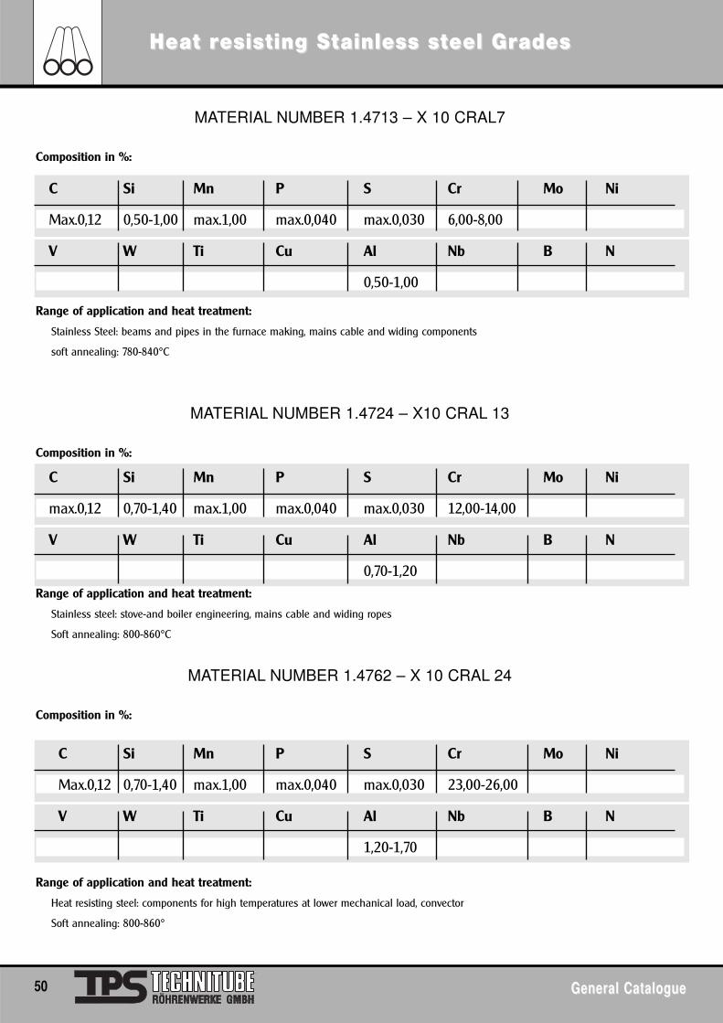
50 General CatalogueGeneral Catalogue
MATERIAL NUMBER 1.4713 – X 10 CRAL7
Composition in %:
Range of application and heat treatment:
Stainless Steel: beams and pipes in the furnace making, mains cable and widing components
soft annealing: 780-840°C
MATERIAL NUMBER 1.4724 – X10 CRAL 13
Composition in %:
Range of application and heat treatment:
Stainless steel: stove-and boiler engineering, mains cable and widing ropes
Soft annealing: 800-860°C
MATERIAL NUMBER 1.4762 – X 10 CRAL 24
Composition in %:
Range of application and heat treatment:
Heat resisting steel: components for high temperatures at lower mechanical load, convector
Soft annealing: 800-860°
C Si Mn P S Cr Mo Ni
Max.0,12 0,70-1,40 max.1,00 max.0,040 max.0,030 23,00-26,00
V W Ti Cu Al Nb B N
1,20-1,70
Heat rHeat resisesisting Sting Sttainless sainless stteel Greel Gradesades
C Si Mn P S Cr Mo Ni
Max.0,12 0,50-1,00 max.1,00 max.0,040 max.0,030 6,00-8,00
V W Ti Cu Al Nb B N
0,50-1,00
C Si Mn P S Cr Mo Ni
max.0,12 0,70-1,40 max.1,00 max.0,040 max.0,030 12,00-14,00
V W Ti Cu Al Nb B N
0,70-1,20
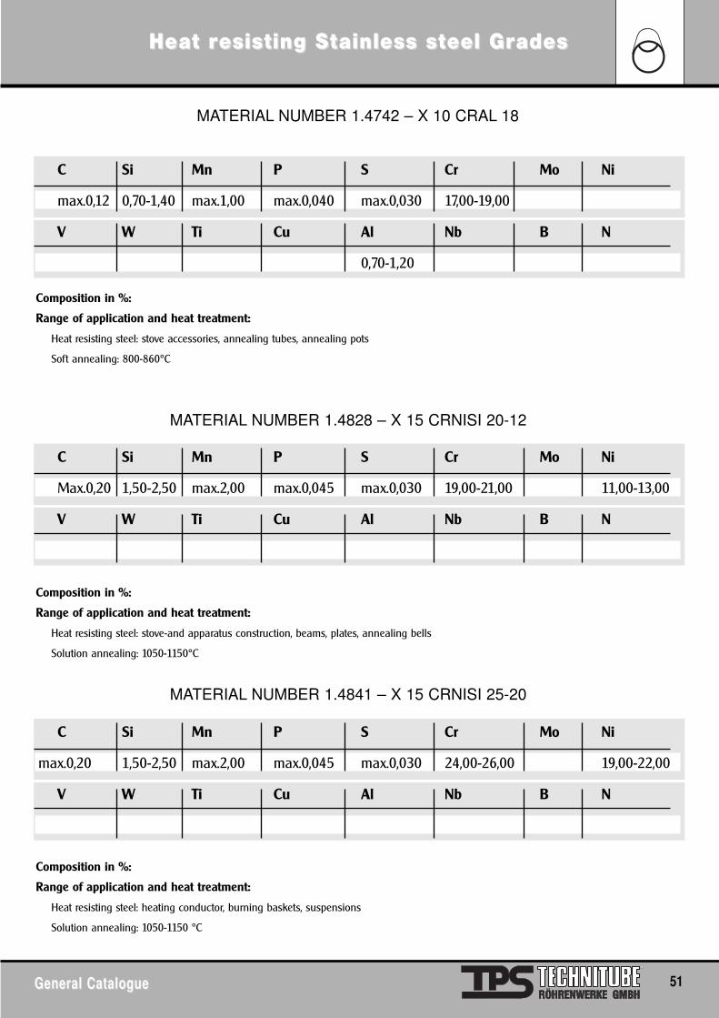
General CatalogueGeneral Catalogue 51
Heat rHeat resisesisting Sting Sttainless sainless stteel Greel Gradesades
MATERIAL NUMBER 1.4742 – X 10 CRAL 18
Composition in %:
Range of application and heat treatment:
Heat resisting steel: stove accessories, annealing tubes, annealing pots
Soft annealing: 800-860°C
MATERIAL NUMBER 1.4828 – X 15 CRNISI 20-12
Composition in %:
Range of application and heat treatment:
Heat resisting steel: stove-and apparatus construction, beams, plates, annealing bells
Solution annealing: 1050-1150°C
MATERIAL NUMBER 1.4841 – X 15 CRNISI 25-20
Composition in %:
Range of application and heat treatment:
Heat resisting steel: heating conductor, burning baskets, suspensions
Solution annealing: 1050-1150 °C
C Si Mn P S Cr Mo Ni
max.0,20 1,50-2,50 max.2,00 max.0,045 max.0,030 24,00-26,00 19,00-22,00
V W Ti Cu Al Nb B N
C Si Mn P S Cr Mo Ni
max.0,12 0,70-1,40 max.1,00 max.0,040 max.0,030 17,00-19,00
V W Ti Cu Al Nb B N
0,70-1,20
C Si Mn P S Cr Mo Ni
Max.0,20 1,50-2,50 max.2,00 max.0,045 max.0,030 19,00-21,00 11,00-13,00
V W Ti Cu Al Nb B N
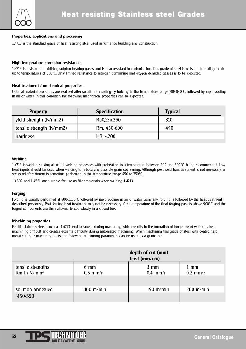
52 General CatalogueGeneral Catalogue
Heat rHeat resisesisting Sting Sttainless sainless stteel Greel Gradesades
Properties, applications and processing
1.4713 is the standard grade of heat resisting steel used in furnance building and construction.
High temperature corrosion resistance1.4713 is resistant to oxidising sulphur bearing gases and is also resistant to carburisation. This grade of steel is resistant to scaling in airup to temperatures of 800°C. Only limited resistance to nitrogen containing and oxygen denuded gasses is to be expected.
Heat treatment / mechanical propertiesOptimal material properties are realised after solution annealing by holding in the temperature range 780-840°C, followed by rapid coolingin air or water. In this condition the following mechanical properties can be expected:
Welding1.4713 is weldable using all usual welding processes with preheating to a temperature between 200 and 300°C, being recommended. Lowheat inputs should be used when welding to reduce any possible grain coarsening. Although post weld heat treatment is not necessary, astress relief treatment is sometime performed in the temperature range 650 to 750°C.
1.4502 and 1.4551 are suitable for use as filler materials when welding 1.4713.
ForgingForging is usually performed at 800-1150°C followed by rapid cooling in air or water. Generally, forging is followed by the heat treatmentdescribed previously. Post forging heat treatment may not be necessary if the temperature of the final forging pass is above 900°C and theforged components are then allowed to cool slowly in a closed box.
Machining propertiesFerritic stainless steels such as 1.4713 tend to smear during machining which results in the formation of longer swarf which makesmachining difficult and creates extreme difficulty during automated machining. When machining this grade of steel with coated hardmetal cutting / machining tools, the following machining parameters can be used as a guideline:
Property Specification Typical
yield strength (N/mm2) Rp0,2: ≥250 310
tensile strength (N/mm2) Rm: 450-600 490
hardness HB: ≤200
depth of cut (mm) feed (mm/rev)
tensile strengths 6 mm 3 mm 1 mmRm in N/mm2 0,5 mm/r 0,4 mm/r 0,2 mm/r
solution annealed 160 m/min 190 m/min 260 m/min(450-550)
General CatalogueGeneral Catalogue 53
Heat rHeat resisesisting Sting Sttainless sainless stteel Greel Gradesades
1.4724 is resistant to oxidising sulphur bearing gases and displays somewhat less, but still good, resistance to sulphur bearing gasses inreducing environments. 1.4724 displays poor resistance to carburising gasses, and is also not resistant to high temperature nitriding,oxygen denuded gasses. This grade of steel is resistant to scaling in air up to temperatures of 850°C.
Heat treatment / mechancial propertiesOptimal material properties are realised after annealing by holding in the temperature range 800-860°C, followed by rapid cooling in airor water. In this condition the following mechanical properties can be expected when testing in the longitudinal direction at roomtemperature:
A slight tendency for grain growth and embrittlement exists at above temperatures of 950°C. It must be noted that any properties that areadversely affected by grain coarsening occurs cannot be recovered by simple thermal treatments.The moderate chromium content and fully ferritic microstructure of this steel makes it susceptible to 475 embrittlement when held attemperatures within the range400 to 550°C. Slow heating or cooling through this temperature range should thus be avoided. The effects of 475 embrittlement can bereversed by briefly heating to within the temperature range 700 to 800°C. This steel is also susceptible to embrittlement by sigma phaseformation within the temperature range 600 to 800°C over long periods of time. The effects of sigma phase formation may be reversed byheating to above 1050°C to take all of the sigma phase into solution again.When heat treatment is performed in a continuos furnace, the upper temperature must be aimed for and in some cases can even beexceeded.
Welding1.4724 is weldable using all usual welding processes with preheating to a temperature between 200 and 300°C, being recommended. Lowheat inputs should be used when welding to reduce any possible grain coarsening effects. Although post weld heat treatment is notnecessary, a stress relief treatment is sometimes performed in the temperature range 750 to 800°C, followed by air cooling, when largedifferences in cross-section exist and/or when the components have been extensively cold worked.1.4723, 1.4820 and 1.4829 are all suitable for use as filler material when welding 1.4724.
Elevated temperature propertiesDue to the much poorer high temperature mechanical properties of 1.4724 compared to the heat resistant austenitic grades, this steel canbe used in applications where the high temperature mechanical requirements are not too great.
ForgingForging is usually performed at 1150-800°C followed by rapid cooling in air or water. Generally, forging is followed by the heat treatmentdescribed previously.
Machining propertiesFerritic stainless steels such as 1.4724 tend to smear during machining which results in the formation of longer swarf thereby makingmachining difficult. When machining this grade of steel with coated hard metal cutting/machining tools, the following machiningparameters can be used as a guideline:
Property Specification Typical
yield strength (N/mm2) Rp0,2: ≥250 360
tensile strength (N/mm2) Rm: 450-650 510
tensile elongation (%) A5: ≥15 18
hardness HB: ≤192
depth of cut (mm) feed (mm/rev)
tensile strengths 6 mm 3 mm 1 mmRm in N/mm2 0,5 mm/r 0,4 mm/r 0,2 mm/r
solution annealed (450-550) 140 m/min 170 m/min 240 m/min
54 General CatalogueGeneral Catalogue
Heat rHeat resisesisting Sting Sttainless sainless stteel Greel Gradesades
High temperature corrosion resistance1.4742 is highly resistant to oxidising sulphur bearing gases and displays somewhat less, but still good, resistance to sulphur bearinggasses in reducing environments. 1.4742 is moderately resistant to carburising gasses, but is not resistant to high temperature nitriding oroxygen denuded gasses. This grade of steel is resistant to scaling in air up to temperatures of 1000°C.
Heat treatment / mechanical propertiesOptimal material properties are realised after annealing by holding in the temperature range 800 – 860°C *, followed by rapid cooling inair or water. In this condition the following mechanical properties can be expected when testing in the longitudinal direction at roomtemperature:
The high chromium content and fully ferritic microstructure of this steel makes it susceptible to 475 embrittlement when held attemperatures within the range 400 to 550°C. Slow heating or cooling through this temperature range should thus be avoided. The effectsof 475 embrittlement can be reversed by briefly heating to within the temperature range 700 to 800 °C. Due to the high chromium contentof this steel, it is susceptible to embrittlement by sigma phase formation within the temperature range 600 to 800°C. The effects of sigmaphase formation may be reversed by heating to above 1050°C to take all of the sigma phase into solution again.A slight tendency for grain growth and embrittlement exists at above temperatures of 950°C. It must be noted that any properties that areadversely affected by grain coarsening occurs cannot be recovered by simple thermal treatments.* When heat treatment is performed in a continuos furnace, the upper temperature must be aimed for and in some cases can even be
exceeded.
Welding 1.4742 is weldable using all usual welding processes with preheating to a temperature between 200 and 300°C, being recommended. Lowheat inputs should be used when welding to reduce any possible grain coarsening. Although post weld heat treatment is not necessary, astress relief treatment is sometimes performed in the temperature range 650 to 800°C when large differences in cross-section exist and/orwhen the components have been extensively cold worked.If an austenitic filler metal is used and the component is destined for use in either a sulphur containing or carburising environment, thenthe austenitic weld bead must be over-laid with a ferritic weld run to ensure some resistance to the operational environment.1.4820 is suitable for use as a filler material when welding 1.4742.
Elevated temperature propertiesDue to the much poorer high temperature mechanical properties of 1.4742, compared to the heat resistant austenitic grades, this steel canonly be used in applications where the high temperature mechanical requirements are not too great.
ForgingForging is usually performed at 1150 – 800°C followed by rapid cooling in air or water. Generally, forging is followed by the heat treatmentdescribed previously.
Machining propertiesFerritic stainless steels such as 1.4742 tend to smear during machining which results in the formation of longer swarf thereby makingmachining difficult. When machining this grade of steel with coated hard metal cutting/machining tools, the following machiningparameters can be used as a guideline:
General comments1.4742 is less formable than the austenitic grades and is best formed within the temperature range 600 to 800°C, especially when thecross section is greater than 3 mm.
Property Specification Typicalyield strength (N/mm2) Rp0,2: ≥ 270 370tensile strength (N/mm2) Rm: 500 – 700 580tensile elongation (%) A5: ≥15 18hardness HB: ≤ 212
depth of cut (mm) feed (mm/rev)
tensile strengths 6 mm 3 mm 1 mmRm in N/mm2 0.5 mm/r 0.4 mm/r 0.2 mm/r
solution annealed (550 – 650) 100 m/min 130 m/min 150 m/min
General CatalogueGeneral Catalogue 55
Heat rHeat resisesisting Sting Sttainless sainless stteel Greel Gradesades
1.4828 is a standard steel grade used for the fabrication of furnace furniture and other high temperature components. Compared with1.4878 and 1.4713, 4828 exhibits superior resistance to scaling. Due to its high tensile strength at elevated temperatures, compared withother grades, 4828 is ideally suited for applications where a greater emphasis is placed on mechanical property requirements.
High temperature corrosion resistance1.4828 has a low resistance to oxidising and reducing sulphur bearing gases. In these gasses, the use of 1.4828 is generally limited totemperatures below 650°C. The resistance to carburising (up to 900°C) and to nitrogen bearing, oxygen depleted gases is average.
Heat treatment/mechanical propertiesOptimal material properties are realised after solution annealing in the temperature range 1050 – 1150°C followed by rapid cooling in airor water. During operation and fabrication, the time spent in the temperature range 550 – 900°C must be minimised to avoidembrittlement, resulting from both chromium carbide precipitation and sigma phase formation. This embrittlement effect can be reversedby solution annealing the steel at a temperature in the range 1050 to 1100°C.In the solution annealed condition the following mechanical properties may be attained when testing in the longitudinal direction at roomtemperature.
Welding4828 is weldable using all usual welding processes with no preheating being required. Low heat inputs should be used when welding,and post weld heat treatment is not necessary. 1.4829 and 4842 are suitable for use as filler materials when welding 4828.Forging is usually performed at 1150 – 800°C followed by rapid cooling in air or water.
Elevated temperature properties
Machining properties:The formation of carbides in 1.4828 will result in increased wear of cutting tools. In addition to this, rapid work hardening and poorthermal conductivity require the use of adequate cooling and good quality cutting/machining tools. It is thus recommended thatmachining is performed in the solution annealed condition using coated hard metal cutting/machining tools and the following machiningparameters as a guideline.
Property Specification Typical- yield strength (N/mm2) Rp0,2: ≥ 230 400- tensile strength (N/mm2) Rm: 550 – 750 675- tensile elongation (%) A5: ≥ 30 45- hardness HB: ≤ 223
depth of cut (mm) feed (mm/rev)
tensile strengths 6 mm 3 mm 1 mmRm in N/mm2 0.5 mm/r 0.4 mm/r 0.2 mm/r
solution annealed (550 – 625) 100 m/min 130 m/min 150 m/min
The followingminimum tensileproperties atvarioustemperatures arewhat can betypically expected ofthis grade of steel.
The temperature-stress-timerelationships thatare important for1.4828 from acreep point of vieware presented inthe graph below:
56 General CatalogueGeneral Catalogue
ComComparparison of Intison of InterernationalnationalNNon Fon Fererrrous Sous Sttandarandardsds
Group DIN code DIN material no. EN code EN material no.Copper OF-Cu 2.0040 Cu-OF CW008A
SE-Cu 2.0070 Cu-PHC/Cu-HPC CW020A/021ASF-Cu 2.0090 Cu-DHP CW024AE-Cu 58 2.0060 Cu-ETP/FRHC CW004A/005A
Low Alloy Copper CuCrZr 2.1293 CuCr1Zr CW106C
Copper-Zinc Alloy CuZn5 2.0220 CuZn5 CW500LCuZn10 2.0230 CuZn10 CW501LCuZn15 2.0240 CuZn15 CW502LCuZn20 2.0250 CuZn20 CW503LCuZn28 2.0260 CuZn28 CW504LCuZn30/33 2.0265/2.0280 CuZn30/33 CW505/506LCuZn36 2.0335 CuZn36 CW507LCuZn37 2.0321 CuZn37 CW508LCuZn40 2.0360 CuZn40 CW509LCuZn37Pb0.5 2.0332 CuZn37Pb0.5 CW604NCuZn36Pb1.5 2.0331 CuZn35Pb1 CW600NCuZn38Pb1.5 2.0371 CuZn38Pb1 CW607NCuZn39Pb0.5 2.0372 CuZn39Pb0.5 CW610NCuZn36Pb3 2.0375 CuZn36Pb3 CW603NCuZn39Pb2 2.0380 CuZn39Pb2 CW612NCuZn40Pb2 2.0402 CuZn40Pb2 CW617NCuZn39Pb3 2.0401 CuZn39Pb3 CW614Nn.V. CuZn36Pb2As CW602NCuZn44Pb2 2.0410 CuZn43Pb2 CW623NCuZn28Sn1 2.0470 CuZn28Sn1As CW706RCuZn31Si1 2.0490 CuZn31Si1 CW708RCuZn35Ni2 2.0540 CuZn35Ni3Mn2AIPb CW710RCuZn37Al1 2.0510 CuZn38Mn1Al CW716RCuZn40Mn2 2.0572 CuZn40Mn2Fe1 CW723RCuZn40Al2 2.0550 CuZn37Mn3Al2SiPb CW713RCuZn20Al2 2.0460 CuZn20Al2As CW720R
Copper-Tin Alloy CuSn4 2.1016 CuSn4 CW450KCuSn6 2.1020 CuSn6 CW452KCuSn8 2.1030 CuSn8 CW453KCuSn6Zn6 2.1080 n.V. n.V.
Copper-Nickel Zinc-Alloy CuNi12Zn24 2.0730 CuNi12Zn24 CW403JCuNi18Zn27 2.0742 CuNi18Zn27 CW410JCuNi18Zn20 2.0740 CuNi18Zn20 CW409JCuNi7Zn39Mn5Pb3 2.0771 n.V. n.V.CuNi12Zn30Pb1 2.0780 CuNi12Zn30Pb1 CW406JCuNi18Zn19Pb1 2.0790 CuNi18Zn19Pb1 CW408J
Copper-Nickel Alloy CuNi10Fe1Mn 2.0872 CuNi10Fe1Mn CW325HCuNi30Mn1Fe 2.0882 CuNi30Mn1Fe CW354HCuNi9Sn2 2.0875 CuNi9Sn2 CW351H
Continuous Cast GC-CuSn7ZnPb 2.1090 CuSn7Zn4Pb7-C-GC CC 493KGC-CuSn12 2.1052 CuSn12-C-GC CC 483KGC-CuPb10Sn 2.1176 CuSn10Pb10-C-GC CC 495KGC-CuPb15Sn 2.1182 CuSn7Pb15-C-GC CC 496KGC-CuSn12Pb 2.1061 CuSn11Pb2-C-GC CC 482KGC-CuSn12Ni 2.1060 CuSn12Ni2-C-GC CC 484K
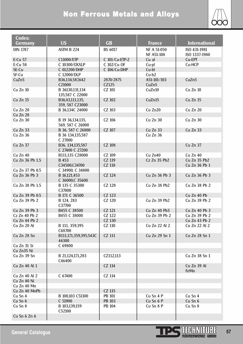
General CatalogueGeneral Catalogue 57
DIN 1787 ASTM B 224 BS 6017 NF A 51-050 ISO 431-1981NF A51-108 ISO 1337-1980
E-Cu 57 C11000/ETP C 101/Cu-ETP-2 Cu al Cu-EPTE-Cu 58 C 10300/OXXLP C 102/Cu OF Cu-pl Cu-HCPSE-Cu C 012200/DHP C 106/Cu-DHP Cu-blSF-Cu C 12000/DLP Cu-b2CuZn5 B36,134,587,642 2870/2875 A51-101/103 CuZn5
C21000 CZ125 CuZn5Cu Zn 10 B 36130,131,134 CZ 101 CuZn10 Cu Zn 10
135,587 C 22000Cu Zn 15 B36,43,111,135, CZ 102 CuZn15 Cu Zn 15
359, 587 C23000Cu Zn 20 B 36,134C 24000 CZ 103 Cu Zn20 Cu Zn 20Cu Zn 28Cu Zn 30 B 19 36,134,135, CZ 106 Cu Zn 30 Cu Zn 30
569, 587 C 26000Cu Zn 33 B 36, 587 C 26800 CZ 107 Cu Zn 33 Cu Zn 33Cu Zn 36 B 36 134,135,587 Cu Zn 36
C 27000Cu Zn 37 B36, 134,135,587 CZ 108 Cu Zn 37
C 27400 C 27200Cu Zn 40 B111,135 C28000 CZ 109 Cu Zn40 Cu Zn 40Cu Zn 36 Pb 1.5 B 453 CZ 119 Cz Zn 35 Pb2 Cu Zn 35 Pb2
C34500,C34700 CZ 118 Cu Zn 36 Pb 1Cu Zn 37 Pb 0.5 C 34900, C 34800Cu Zn 36 Pb 3 B 16,121,453 CZ 124 Cu Zn 36 Pb 3 Cu Zn 36 Pb 3
C 36000,C 35600Cu Zn 38 Pb 1.5 B 135 C 35300 CZ 128 Cu Zn 38 Pb2 Cu Zn 38 Pb 2
C37000Cu Zn 39 Pb 0.5 B 171 C 36500 CZ 123 Cu Zn 40 PbCu Zn 39 Pb 2 B 124, 283 CZ 120 Cu Zn 39 Pb2 Cu Zn 39 Pb 2
C37700Cu Zn 39 Pb 3 B455 C 38500 CZ 121 Cu Zn 40 Pb3 Cu Zn 40 Pb 3Cz Zn 40 Pb 2 B455 C 38000 CZ 122 Cu Zn 39 Pb 2 Cu Zn 39 Pb 2Cu Zn 44 Pb 2 CZ 130 Cu Zn 43 Pb 2Cu Zn 20 Al B 111, 359,395 CZ 110 Cu Zn 22 Al 2 Cu Zn 22 Al 2
C68700Cu Zn 28 Sn B111,171,359,395,543C CZ 111 Cu Zn 29 Sn 1 Cu Zn 28 Sn 1
44300Cu Zn 31 Si C 69800Cu Zn35 NiCu Zn 39 Sn B 21,124,171,283 CZ112,113 Cu Zn 38 Sn 1
C46400Cu Zn 40 Al 1 CZ 114 Cu Zn 39 Al
FeMnCu Zn 40 Al 2 C 67400 CZ 114Cu Zn 40 NiCu Zn 40 MnCu Zn 40 MnPb CZ 115Cu Sn 4 B 100,103 C51100 PB 101 Cu Sn 4 P Cu Sn 4Cu Sn 6 C 51900 PB 103 Cu Sn 6 P Cu Sn 6Cu Sn 8 B 103,139,159 PB 104 Cu Sn 8 P Cu Sn 8
C52100Cu Sn 6 Zn 6
Codes:Germany US GB France International
NNon Fon Fererrrous Meous Mettals and Alloals and Alloyyss
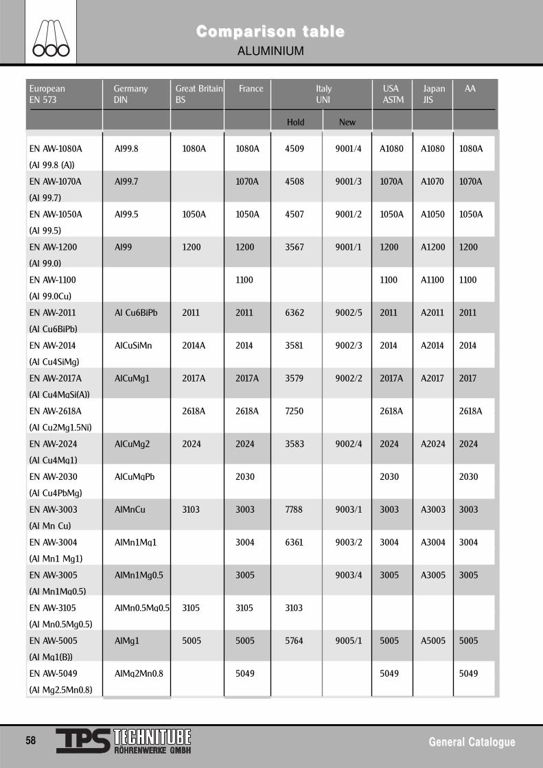
58 General CatalogueGeneral Catalogue
European Germany Great Britain France Italy USA Japan AAEN 573 DIN BS UNI ASTM JIS
Hold New
EN AW-1080A Al99.8 1080A 1080A 4509 9001/4 A1080 A1080 1080A
(Al 99.8 (A))
EN AW-1070A Al99.7 1070A 4508 9001/3 1070A A1070 1070A
(Al 99.7)
EN AW-1050A Al99.5 1050A 1050A 4507 9001/2 1050A A1050 1050A
(Al 99.5)
EN AW-1200 Al99 1200 1200 3567 9001/1 1200 A1200 1200
(Al 99.0)
EN AW-1100 1100 1100 A1100 1100
(Al 99.0Cu)
EN AW-2011 Al Cu6BiPb 2011 2011 6362 9002/5 2011 A2011 2011
(Al Cu6BiPb)
EN AW-2014 AlCuSiMn 2014A 2014 3581 9002/3 2014 A2014 2014
(Al Cu4SiMg)
EN AW-2017A AlCuMg1 2017A 2017A 3579 9002/2 2017A A2017 2017
(Al Cu4MgSi(A))
EN AW-2618A 2618A 2618A 7250 2618A 2618A
(Al Cu2Mg1.5Ni)
EN AW-2024 AlCuMg2 2024 2024 3583 9002/4 2024 A2024 2024
(Al Cu4Mg1)
EN AW-2030 AlCuMgPb 2030 2030 2030
(Al Cu4PbMg)
EN AW-3003 AlMnCu 3103 3003 7788 9003/1 3003 A3003 3003
(Al Mn Cu)
EN AW-3004 AlMn1Mg1 3004 6361 9003/2 3004 A3004 3004
(Al Mn1 Mg1)
EN AW-3005 AlMn1Mg0.5 3005 9003/4 3005 A3005 3005
(Al Mn1Mg0.5)
EN AW-3105 AlMn0.5Mg0.5 3105 3105 3103
(Al Mn0.5Mg0.5)
EN AW-5005 AlMg1 5005 5005 5764 9005/1 5005 A5005 5005
(Al Mg1(B))
EN AW-5049 AlMg2Mn0.8 5049 5049 5049
(Al Mg2.5Mn0.8)
ComComparparison tison tableableALUMINIUM
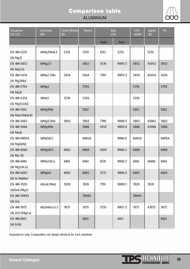
General CatalogueGeneral Catalogue 59
European Germany Great Britain France Italy USA Japan AAEN 573 DIN BS UNI ASTM JIS
Hold New
EN AW-5251 AlMg2Mn0.3 5251 5251 4511 5251 5251
(Al Mg2)
EN AW-5052 AlMg2.5 5052 3574 9005/2 5052 A5052 5052
(Al Mg2.5)
EN AW-5454 AlMg2.7Mn 5454 5454 7789 9005/3 5454 A5454 5454
(Al Mg3Mn)
EN AW-5754 AlMg3 5754 5754 5754
(Al Mg3)
EN AW-5356 AlMg5 3576 5356 5356
(Al Mg5Cr(A))
EN AW-5182 AlMg5Mn 5182 5182 5182
(Al Mg4.5Mn0.4)
EN AW-5083 AlMg4.5Mn 5083 5083 7790 9004/5 5083 A5083 5083
EN AW-5086 AlMg4Mn 5086 5452 9005/4 5086 A5086 5086
(Al Mg4)
EN AW-6005A AlMgSi0.7 6005A 9006/6 6005A 6005A
(Al MgSi(A))
EN AW-6060 AlMgSi0.5 6063 6060 3569 9006/1 6060 6060
(Al Mg Si)
EN AW-6061 AlMg1SiCu 6061 6061 6170 9006/2 6061 A6061 6061
(Al Mg1SiCu)
EN AW-6082 AlMgSi1 6082 6082 3571 9006/4 6082 6082
(Al Si MgMn)
EN AW-7020 AlZn4.5Mg1 7020 7020 7791 9009/1 7020 7020
(AlZn4.5Mg1)
EN AW-7049A 7049A 7049A
(Al Zn)
EN AW-7075 AlZnMgCu1.5 7075 7075 3735 9007/2 7075 A7075 7075
(Al Zn5.5MgCu)
EN AW-8011 8011 8011 8011
(Al FeSi)
Equivalence only. Composition not always identical for each standard.
ComComparparison tison tableableALUMINIUM
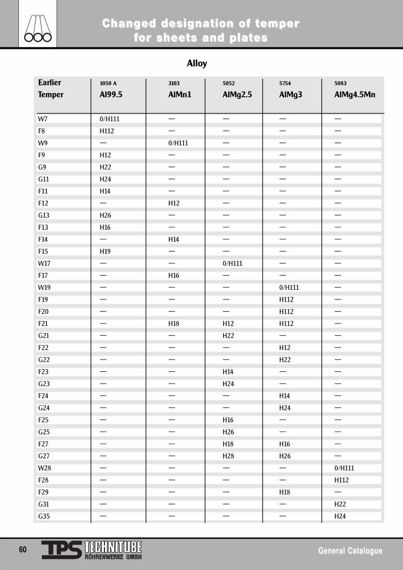
60 General CatalogueGeneral Catalogue
ChangChanged designation of ted designation of tememper per ffor sheeor sheets and platts and plateses
Alloy
Earlier 1050 A 3103 5052 5754 5083
Temper Al99.5 AlMn1 AlMg2.5 AlMg3 AlMg4.5Mn
W7 0/H111 — — — —
F8 H112 — — — —
W9 — 0/H111 — — —
F9 H12 — — — —
G9 H22 — — — —
G11 H24 — — — —
F11 H14 — — — —
F12 — H12 — — —
G13 H26 — — — —
F13 H16 — — — —
F14 — H14 — — —
F15 H19 — — — —
W17 — — 0/H111 — —
F17 — H16 — — —
W19 — — — 0/H111 —
F19 — — — H112 —
F20 — — — H112 —
F21 — H18 H12 H112 —
G21 — — H22 — —
F22 — — — H12 —
G22 — — — H22 —
F23 — — H14 — —
G23 — — H24 — —
F24 — — — H14 —
G24 — — — H24 —
F25 — — H16 — —
G25 — — H26 — —
F27 — — H18 H16 —
G27 — — H28 H26 —
W28 — — — — 0/H111
F28 — — — — H112
F29 — — — H18 —
G31 — — — — H22
G35 — — — — H24
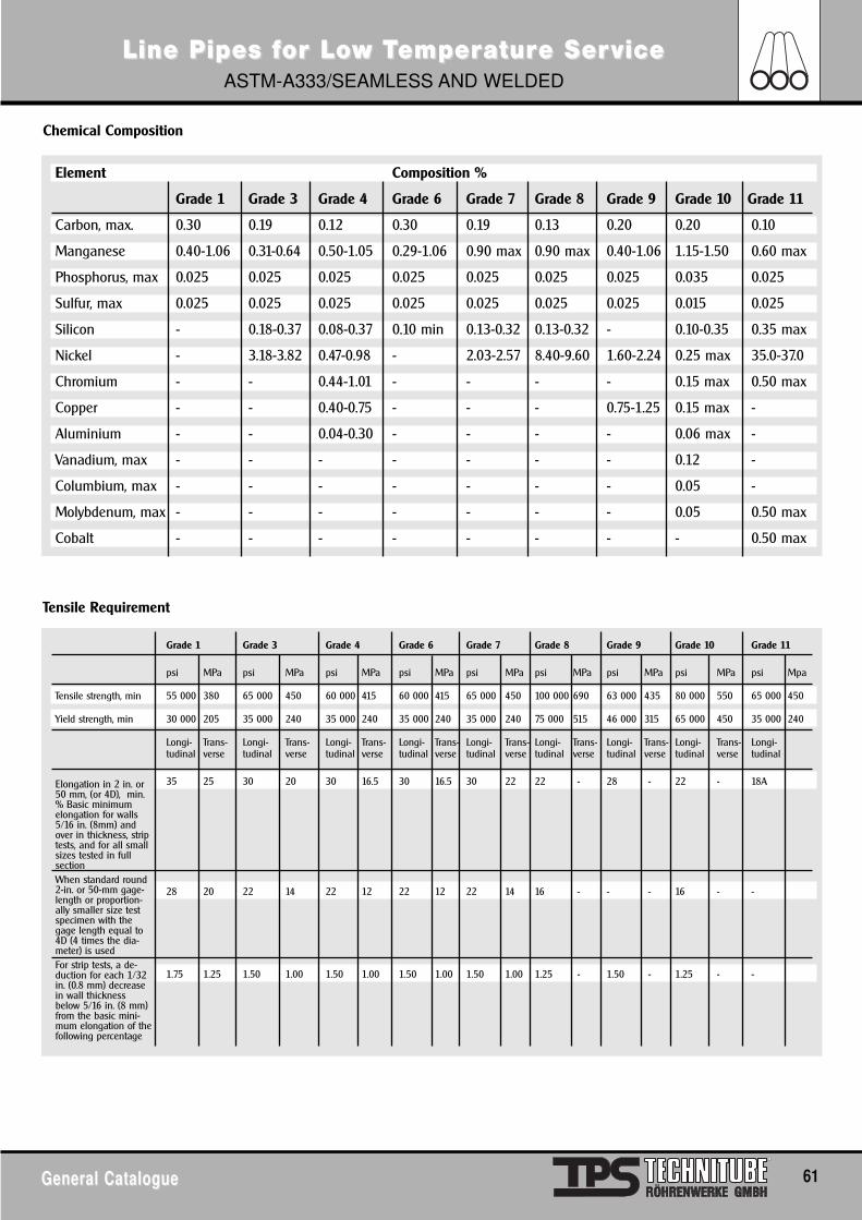
General CatalogueGeneral Catalogue 61
Line Pipes fLine Pipes for Loor Low Tw Tememperperaturature Sere ServiceviceASTM-A333/SEAMLESS AND WELDED
Chemical Composition
Tensile Requirement
Element Composition %
Grade 1 Grade 3 Grade 4 Grade 6 Grade 7 Grade 8 Grade 9 Grade 10 Grade 11
Carbon, max. 0.30 0.19 0.12 0.30 0.19 0.13 0.20 0.20 0.10
Manganese 0.40-1.06 0.31-0.64 0.50-1.05 0.29-1.06 0.90 max 0.90 max 0.40-1.06 1.15-1.50 0.60 max
Phosphorus, max 0.025 0.025 0.025 0.025 0.025 0.025 0.025 0.035 0.025
Sulfur, max 0.025 0.025 0.025 0.025 0.025 0.025 0.025 0.015 0.025
Silicon - 0.18-0.37 0.08-0.37 0.10 min 0.13-0.32 0.13-0.32 - 0.10-0.35 0.35 max
Nickel - 3.18-3.82 0.47-0.98 - 2.03-2.57 8.40-9.60 1.60-2.24 0.25 max 35.0-37.0
Chromium - - 0.44-1.01 - - - - 0.15 max 0.50 max
Copper - - 0.40-0.75 - - - 0.75-1.25 0.15 max -
Aluminium - - 0.04-0.30 - - - - 0.06 max -
Vanadium, max - - - - - - - 0.12 -
Columbium, max - - - - - - - 0.05 -
Molybdenum, max - - - - - - - 0.05 0.50 max
Cobalt - - - - - - - - 0.50 max
Grade 1 Grade 3 Grade 4 Grade 6 Grade 7 Grade 8 Grade 9 Grade 10 Grade 11
psi MPa psi MPa psi MPa psi MPa psi MPa psi MPa psi MPa psi MPa psi Mpa
Tensile strength, min 55 000 380 65 000 450 60 000 415 60 000 415 65 000 450 100 000 690 63 000 435 80 000 550 65 000 450
Yield strength, min 30 000 205 35 000 240 35 000 240 35 000 240 35 000 240 75 000 515 46 000 315 65 000 450 35 000 240
Longi- Trans- Longi- Trans- Longi- Trans- Longi- Trans- Longi- Trans- Longi- Trans- Longi- Trans- Longi- Trans- Longi-tudinal verse tudinal verse tudinal verse tudinal verse tudinal verse tudinal verse tudinal verse tudinal verse tudinal
35 25 30 20 30 16.5 30 16.5 30 22 22 - 28 - 22 - 18A
28 20 22 14 22 12 22 12 22 14 16 - - - 16 - -
1.75 1.25 1.50 1.00 1.50 1.00 1.50 1.00 1.50 1.00 1.25 - 1.50 - 1.25 - -
Elongation in 2 in. or50 mm, (or 4D), min.% Basic minimumelongation for walls5/16 in. (8mm) andover in thickness, striptests, and for all smallsizes tested in full section When standard round2-in. or 50-mm gage-length or proportion-ally smaller size testspecimen with thegage length equal to4D (4 times the dia-meter) is usedFor strip tests, a de-duction for each 1/32in. (0.8 mm) decreasein wall thicknessbelow 5/16 in. (8 mm)from the basic mini-mum elongation of thefollowing percentage
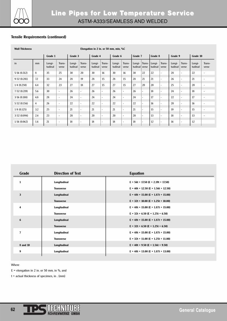
62 General CatalogueGeneral Catalogue
Line Pipes fLine Pipes for Loor Low Tw Tememperperaturature Sere ServiceviceASTM-A333/SEAMLESS AND WELDED
Tensile Requirements (continued)
Where
E = elongation in 2 in. or 50 mm, in %, and
t = actual thickness of specimen, in . (mm)
Grade Direction of Test Equation
1 Longitudinal E = 56t + 17.50 (E = 2.19t + 17.50)
Transverse E = 40t + 12.50 (E = 1.56t + 12.50)
3 Longitudinal E = 48t + 15.00 (E = 1.87t + 15.00)
Transverse E = 32t + 10.00 (E = 1.25t + 10.00)
4 Longitudinal E = 48t + 15.00 (E = 1.87t + 15.00)
Transverse E = 32t + 6.50 (E = 1.25t + 6.50)
6 Longitudinal E = 48t + 15.00 (E = 1.87t + 15.00)
Transverse E = 32t + 6.50 (E = 1.25t + 6.50)
7 Longitudinal E = 48t + 15.00 (E = 1.87t + 15.00)
Transverse E = 32t + 11.00 (E = 1.25t + 11.00)
8 and 10 Longitudinal E = 40t + 9.50 (E = 1.56t + 9.50)
9 Longitudinal E = 48t + 13.00 (E = 1.87t + 13.00)
Wall Thickness Elongation in 2 in. or 50 mm, min, %C
Grade 1 Grade 3 Grade 4 Grade 6 Grade 7 Grade 8 Grade 9 Grade 10
in mm Longi- Trans- Longi- Trans- Longi- Trans- Longi- Trans- Longi- Trans- Longi- Trans- Longi- Trans- Longi- Trans-tudinal verse tudinal verse tudinal verse tudinal verse tudinal verse tudinal verse tudinal verse tudinal verse
5/16 (0.312) 8 35 25 30 20 30 16 30 16 30 22 22 - 28 - 22 -
9/32 (0.281) 7.2 33 24 28 19 28 15 28 15 28 21 21 - 26 - 21 -
1/4 (0.250) 6.4 32 23 27 18 27 15 27 15 27 20 20 - 25 - 20 -
7/32 (0.219) 5.6 30 - 26 - 26 - 26 - 26 - 18 - 24 - 18 -
3/16 (0.188) 4.8 28 - 24 - 24 - 24 - 24 - 17 - 22 - 17 -
5/32 (0.156) 4 26 - 22 - 22 - 22 - 22 - 16 - 20 - 16 -
1/8 (0.125) 3.2 25 - 21 - 21 - 21 - 21 - 15 - 19 - 15 -
3/32 (0.094) 2.4 23 - 20 - 20 - 20 - 20 - 13 - 18 - 13 -
1/16 (0.062) 1.6 21 - 18 - 18 - 18 - 18 - 12 - 16 - 12
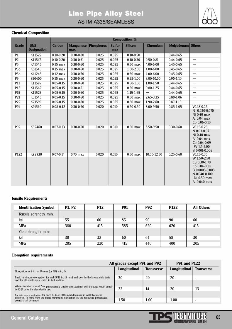
General CatalogueGeneral Catalogue 63
Line Pipe AlloLine Pipe Alloy Sy StteeleelASTM-A335/SEAMLESS
P1 K11522 0.10-0.20 0.30-0.80 0.025 0.025 0.10-0.50 — 0.44-0.65 —P2 K11547 0.10-0.20 0.30-0.61 0.025 0.025 0.10-0.30 0.50-0.81 0.44-0.65 —P5 K41545 0.15 max 0.30-0.60 0.025 0.025 0.50 max 4.00-6.00 0.45-0.65 —P5b K51545 0.15 max 0.30-0.60 0.025 0.025 1.00-2.00 4.00-6.00 0.45-0.65 —P5c K41245 0.12 max 0.30-0.60 0.025 0.025 0.50 max 4.00-6.00 0.45-0.65 —P9 S50400 0.15 max 0.30-0.60 0.025 0.025 0.25-1.00 8.00-10.00 0.90-1.10 —P11 K11597 0.05-0.15 0.30-0.60 0.025 0.025 0.50-1.00 1.00-1.50 0.44-0.65 —P12 K11562 0.05-0.15 0.30-0.61 0.025 0.025 0.50 max 0.80-1.25 0.44-0.65 —P15 K11578 0.05-0.15 0.30-0.60 0.025 0.025 1.15-1.65 — 0.44-0.65 —P21 K31545 0.05-0.15 0.30-0.60 0.025 0.025 0.50 max 2.65-3.35 0.80-1.06 —P22 K21590 0.05-0.15 0.30-0.60 0.025 0.025 0.50 max 1.90-2.60 0.87-1.13 —P91 K91560 0.08-0.12 0.30-0.60 0.020 0.010 0.20-0.50 8.00-9.50 0.85-1.05 V0.18-0.25
N 0.030-0.070Ni 0.40 maxAl 0.04 maxCb 0.06-0.10
P92 K92460 0.07-0.13 0.30-0.60 0.020 0.010 0.50 max 8.50-9.50 0.30-0.60 V0.15-0.25N 0.03-0.07Ni 0.40 maxAl 0.04 maxCb 0.04-0.09W 1.5-2.00
B 0.001-0.006P122 K92930 0.07-0.14 0.70 max 0.020 0.010 0.50 max 10.00-12.50 0.25-0.60 V0.15-0.30
W 1.50-2.50Cu 0.30-1.70Cb 0.04-0.10B 0.0005-0.005N 0.040-0.100Ni 0.50 max
Al 0.040 max
Composition, %
Grade UNS Carbon Manganese Phosphorus Sulfur Silicon Chromium Molybdenum OthersDesignation max. max
Chemical Composition
Tensile Requirements
Elongation requirements
Identification Symbol P1, P2 P12 P91 P92 P122 All Others
Tensile sgrength, min:ksi 55 60 85 90 90 60MPa 380 415 585 620 620 415Yield strength, min:ksi 30 32 60 64 58 30MPa 205 220 415 440 400 205
All grades except P91 and P92 P91 and P122Longitudinal Transverse Longitudinal Transverse
30 20 20 -
22 14 20 13
1.50 1.00 1.00 -
Elongation in 2 in. or 50 mm, (or 4D), min, %:
Basic minimum elongation for wall 5/16 in. (8 mm) and over in thickness, strip tests,and for all small sizes tested in full section.
When standard round 2-in. proportionally smaller size specimen with the gage length equalto 4D (4 times the diameter) is use.
For strip tests a deduction for each 1/32-in. (0.8 mm) decrease in wall thickness below in. (8 mm) from the basic minimum elongation of, the following percentagepoints shall be made
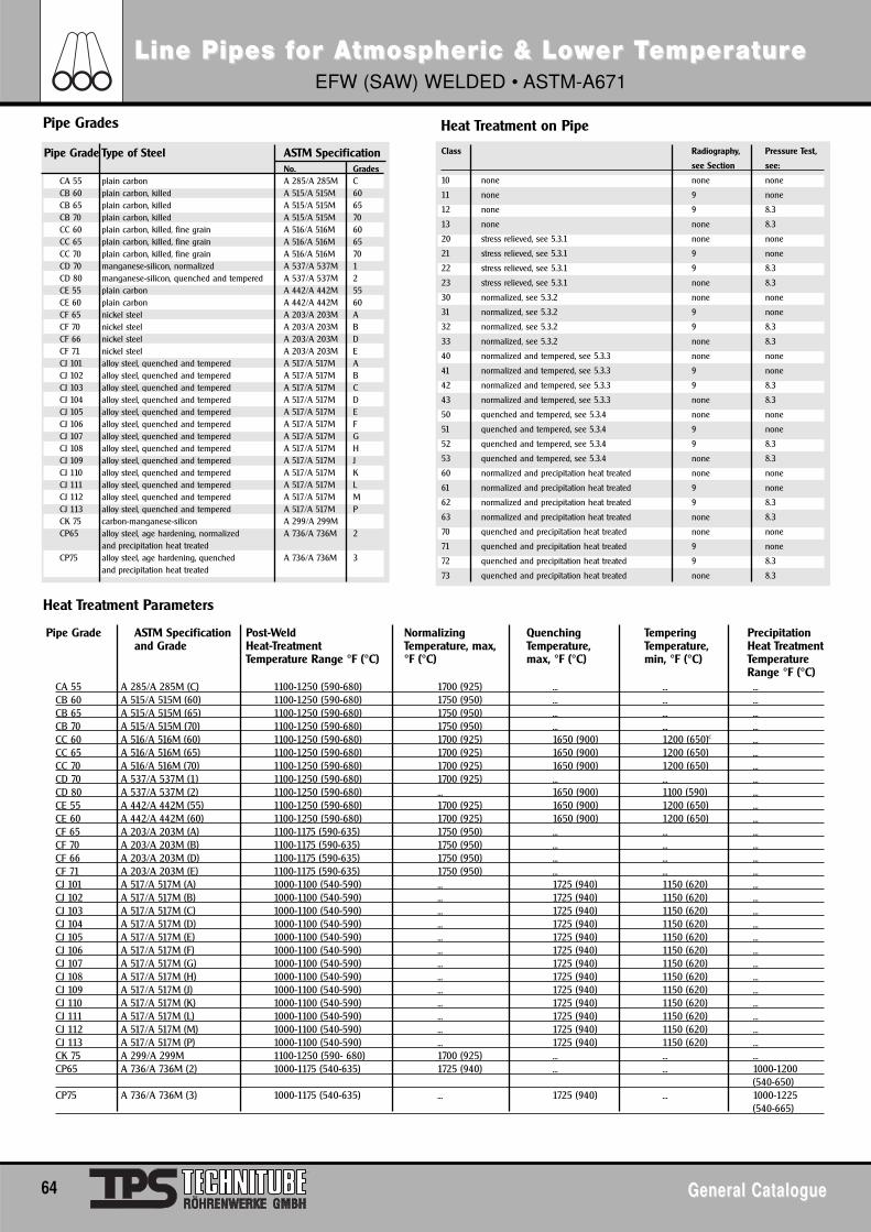
64 General CatalogueGeneral Catalogue
Line Pipes fLine Pipes for Aor Atmosphertmospheric & Loic & Lowwer Ter TememperperaturatureeEFW (SAW) WELDED • ASTM-A671
Pipe Grades
Heat Treatment Parameters
Heat Treatment on Pipe
CA 55 A 285/A 285M (C) 1100-1250 (590-680) 1700 (925) ... ... ...CB 60 A 515/A 515M (60) 1100-1250 (590-680) 1750 (950) ... ... ...CB 65 A 515/A 515M (65) 1100-1250 (590-680) 1750 (950) ... ... ...CB 70 A 515/A 515M (70) 1100-1250 (590-680) 1750 (950) ... ... ...CC 60 A 516/A 516M (60) 1100-1250 (590-680) 1700 (925) 1650 (900) 1200 (650)C ...CC 65 A 516/A 516M (65) 1100-1250 (590-680) 1700 (925) 1650 (900) 1200 (650) ...CC 70 A 516/A 516M (70) 1100-1250 (590-680) 1700 (925) 1650 (900) 1200 (650) ...CD 70 A 537/A 537M (1) 1100-1250 (590-680) 1700 (925) ... ... ...CD 80 A 537/A 537M (2) 1100-1250 (590-680) ... 1650 (900) 1100 (590) ...CE 55 A 442/A 442M (55) 1100-1250 (590-680) 1700 (925) 1650 (900) 1200 (650) ...CE 60 A 442/A 442M (60) 1100-1250 (590-680) 1700 (925) 1650 (900) 1200 (650) ...CF 65 A 203/A 203M (A) 1100-1175 (590-635) 1750 (950) ... ... ...CF 70 A 203/A 203M (B) 1100-1175 (590-635) 1750 (950) ... ... ...CF 66 A 203/A 203M (D) 1100-1175 (590-635) 1750 (950) ... ... ...CF 71 A 203/A 203M (E) 1100-1175 (590-635) 1750 (950) ... ... ...CJ 101 A 517/A 517M (A) 1000-1100 (540-590) ... 1725 (940) 1150 (620) ...CJ 102 A 517/A 517M (B) 1000-1100 (540-590) ... 1725 (940) 1150 (620) ...CJ 103 A 517/A 517M (C) 1000-1100 (540-590) ... 1725 (940) 1150 (620) ...CJ 104 A 517/A 517M (D) 1000-1100 (540-590) ... 1725 (940) 1150 (620) ...CJ 105 A 517/A 517M (E) 1000-1100 (540-590) ... 1725 (940) 1150 (620) ...CJ 106 A 517/A 517M (F) 1000-1100 (540-590) ... 1725 (940) 1150 (620) ...CJ 107 A 517/A 517M (G) 1000-1100 (540-590) ... 1725 (940) 1150 (620) ...CJ 108 A 517/A 517M (H) 1000-1100 (540-590) ... 1725 (940) 1150 (620) ...CJ 109 A 517/A 517M (J) 1000-1100 (540-590) ... 1725 (940) 1150 (620) ...CJ 110 A 517/A 517M (K) 1000-1100 (540-590) ... 1725 (940) 1150 (620) ...CJ 111 A 517/A 517M (L) 1000-1100 (540-590) ... 1725 (940) 1150 (620) ...CJ 112 A 517/A 517M (M) 1000-1100 (540-590) ... 1725 (940) 1150 (620) ...CJ 113 A 517/A 517M (P) 1000-1100 (540-590) ... 1725 (940) 1150 (620) ...CK 75 A 299/A 299M 1100-1250 (590- 680) 1700 (925) ... ... ...CP65 A 736/A 736M (2) 1000-1175 (540-635) 1725 (940) ... ... 1000-1200
(540-650)CP75 A 736/A 736M (3) 1000-1175 (540-635) ... 1725 (940) ... 1000-1225
(540-665)
Class Radiography, Pressure Test,
see Section see:
10 none none none
11 none 9 none
12 none 9 8.3
13 none none 8.3
20 stress relieved, see 5.3.1 none none
21 stress relieved, see 5.3.1 9 none
22 stress relieved, see 5.3.1 9 8.3
23 stress relieved, see 5.3.1 none 8.3
30 normalized, see 5.3.2 none none
31 normalized, see 5.3.2 9 none
32 normalized, see 5.3.2 9 8.3
33 normalized, see 5.3.2 none 8.3
40 normalized and tempered, see 5.3.3 none none
41 normalized and tempered, see 5.3.3 9 none
42 normalized and tempered, see 5.3.3 9 8.3
43 normalized and tempered, see 5.3.3 none 8.3
50 quenched and tempered, see 5.3.4 none none
51 quenched and tempered, see 5.3.4 9 none
52 quenched and tempered, see 5.3.4 9 8.3
53 quenched and tempered, see 5.3.4 none 8.3
60 normalized and precipitation heat treated none none
61 normalized and precipitation heat treated 9 none
62 normalized and precipitation heat treated 9 8.3
63 normalized and precipitation heat treated none 8.3
70 quenched and precipitation heat treated none none
71 quenched and precipitation heat treated 9 none
72 quenched and precipitation heat treated 9 8.3
73 quenched and precipitation heat treated none 8.3
Pipe Grade Type of Steel ASTM SpecificationNo. Grades
CA 55 plain carbon A 285/A 285M CCB 60 plain carbon, killed A 515/A 515M 60CB 65 plain carbon, killed A 515/A 515M 65CB 70 plain carbon, killed A 515/A 515M 70CC 60 plain carbon, killed, fine grain A 516/A 516M 60CC 65 plain carbon, killed, fine grain A 516/A 516M 65CC 70 plain carbon, killed, fine grain A 516/A 516M 70CD 70 manganese-silicon, normalized A 537/A 537M 1CD 80 manganese-silicon, quenched and tempered A 537/A 537M 2CE 55 plain carbon A 442/A 442M 55CE 60 plain carbon A 442/A 442M 60CF 65 nickel steel A 203/A 203M ACF 70 nickel steel A 203/A 203M BCF 66 nickel steel A 203/A 203M DCF 71 nickel steel A 203/A 203M ECJ 101 alloy steel, quenched and tempered A 517/A 517M ACJ 102 alloy steel, quenched and tempered A 517/A 517M BCJ 103 alloy steel, quenched and tempered A 517/A 517M CCJ 104 alloy steel, quenched and tempered A 517/A 517M DCJ 105 alloy steel, quenched and tempered A 517/A 517M ECJ 106 alloy steel, quenched and tempered A 517/A 517M FCJ 107 alloy steel, quenched and tempered A 517/A 517M GCJ 108 alloy steel, quenched and tempered A 517/A 517M HCJ 109 alloy steel, quenched and tempered A 517/A 517M JCJ 110 alloy steel, quenched and tempered A 517/A 517M KCJ 111 alloy steel, quenched and tempered A 517/A 517M LCJ 112 alloy steel, quenched and tempered A 517/A 517M MCJ 113 alloy steel, quenched and tempered A 517/A 517M PCK 75 carbon-manganese-silicon A 299/A 299MCP65 alloy steel, age hardening, normalized A 736/A 736M 2
and precipitation heat treatedCP75 alloy steel, age hardening, quenched A 736/A 736M 3
and precipitation heat treated
Pipe Grade ASTM Specification Post-Weld Normalizing Quenching Tempering Precipitationand Grade Heat-Treatment Temperature, max, Temperature, Temperature, Heat Treatment
Temperature Range °F (°C) °F (°C) max, °F (°C) min, °F (°C) TemperatureRange °F (°C)
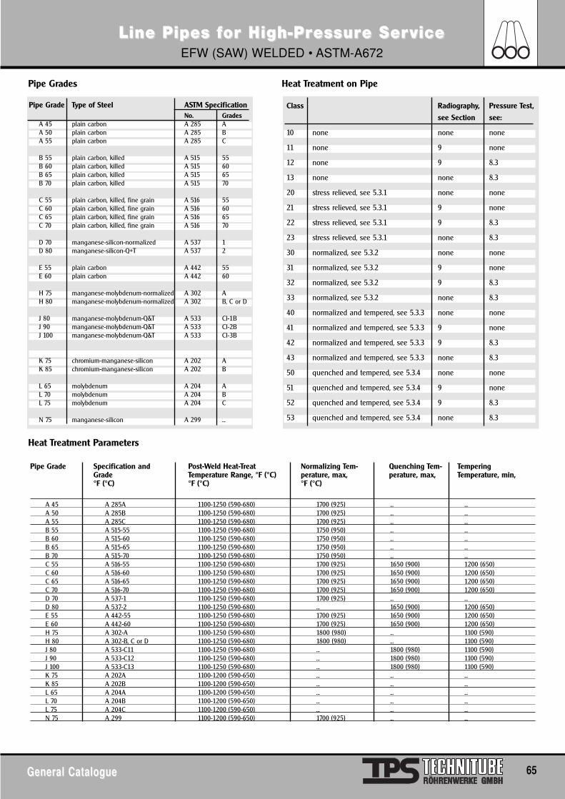
General CatalogueGeneral Catalogue 65
Class Radiography, Pressure Test,
see Section see:
10 none none none
11 none 9 none
12 none 9 8.3
13 none none 8.3
20 stress relieved, see 5.3.1 none none
21 stress relieved, see 5.3.1 9 none
22 stress relieved, see 5.3.1 9 8.3
23 stress relieved, see 5.3.1 none 8.3
30 normalized, see 5.3.2 none none
31 normalized, see 5.3.2 9 none
32 normalized, see 5.3.2 9 8.3
33 normalized, see 5.3.2 none 8.3
40 normalized and tempered, see 5.3.3 none none
41 normalized and tempered, see 5.3.3 9 none
42 normalized and tempered, see 5.3.3 9 8.3
43 normalized and tempered, see 5.3.3 none 8.3
50 quenched and tempered, see 5.3.4 none none
51 quenched and tempered, see 5.3.4 9 none
52 quenched and tempered, see 5.3.4 9 8.3
53 quenched and tempered, see 5.3.4 none 8.3
Pipe Grade Type of Steel ASTM SpecificationNo. Grades
A 45 plain carbon A 285 AA 50 plain carbon A 285 BA 55 plain carbon A 285 C
B 55 plain carbon, killed A 515 55B 60 plain carbon, killed A 515 60B 65 plain carbon, killed A 515 65B 70 plain carbon, killed A 515 70
C 55 plain carbon, killed, fine grain A 516 55C 60 plain carbon, killed, fine grain A 516 60C 65 plain carbon, killed, fine grain A 516 65C 70 plain carbon, killed, fine grain A 516 70
D 70 manganese-silicon-normalized A 537 1D 80 manganese-silicon-Q+T A 537 2
E 55 plain carbon A 442 55E 60 plain carbon A 442 60
H 75 manganese-molybdenum-normalized A 302 AH 80 manganese-molybdenum-normalized A 302 B, C or D
J 80 manganese-molybdenum-Q&T A 533 Cl-1BJ 90 manganese-molybdenum-Q&T A 533 Cl-2BJ 100 manganese-molybdenum-Q&T A 533 Cl-3B
K 75 chromium-manganese-silicon A 202 AK 85 chromium-manganese-silicon A 202 B
L 65 molybdenum A 204 AL 70 molybdenum A 204 BL 75 molybdenum A 204 C
N 75 manganese-silicon A 299 ...
Line Pipes fLine Pipes for High-Pror High-Pressuressure Sere ServiceviceEFW (SAW) WELDED • ASTM-A672
Pipe Grades
Heat Treatment Parameters
Heat Treatment on Pipe
A 45 A 285A 1100-1250 (590-680) 1700 (925) ... ...A 50 A 285B 1100-1250 (590-680) 1700 (925) ... ...A 55 A 285C 1100-1250 (590-680) 1700 (925) ... ...B 55 A 515-55 1100-1250 (590-680) 1750 (950) ... ...B 60 A 515-60 1100-1250 (590-680) 1750 (950) ... ...B 65 A 515-65 1100-1250 (590-680) 1750 (950) ... ...B 70 A 515-70 1100-1250 (590-680) 1750 (950) ... ...C 55 A 516-55 1100-1250 (590-680) 1700 (925) 1650 (900) 1200 (650)C 60 A 516-60 1100-1250 (590-680) 1700 (925) 1650 (900) 1200 (650)C 65 A 516-65 1100-1250 (590-680) 1700 (925) 1650 (900) 1200 (650)C 70 A 516-70 1100-1250 (590-680) 1700 (925) 1650 (900) 1200 (650)D 70 A 537-1 1100-1250 (590-680) 1700 (925) ... ...D 80 A 537-2 1100-1250 (590-680) ... 1650 (900) 1200 (650)E 55 A 442-55 1100-1250 (590-680) 1700 (925) 1650 (900) 1200 (650)E 60 A 442-60 1100-1250 (590-680) 1700 (925) 1650 (900) 1200 (650)H 75 A 302-A 1100-1250 (590-680) 1800 (980) ... 1100 (590)H 80 A 302-B, C or D 1100-1250 (590-680) 1800 (980) ... 1100 (590)J 80 A 533-C11 1100-1250 (590-680) ... 1800 (980) 1100 (590)J 90 A 533-C12 1100-1250 (590-680) ... 1800 (980) 1100 (590)J 100 A 533-C13 1100-1250 (590-680) ... 1800 (980) 1100 (590)K 75 A 202A 1100-1200 (590-650) ... ... ...K 85 A 202B 1100-1200 (590-650) ... ... ...L 65 A 204A 1100-1200 (590-650) ... ... ...L 70 A 204B 1100-1200 (590-650) ... ... ...L 75 A 204C 1100-1200 (590-650) ... ... ...N 75 A 299 1100-1200 (590-650) 1700 (925) ... ...
Pipe Grade Specification and Post-Weld Heat-Treat Normalizing Tem- Quenching Tem- TemperingGrade Temperature Range, °F (°C) perature, max, perature, max, Temperature, min,°F (°C) °F (°C) °F (°C)
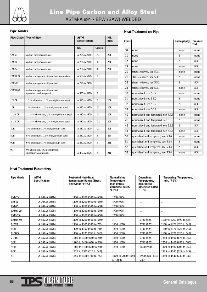
66 General CatalogueGeneral Catalogue
10 none none none
11 none 9 none
12 none 9 8.3
13 none none 8.3
20 stress relieved, see 5.3.1 none none
21 stress relieved, see 5.3.1 9 none
22 stress relieved, see 5.3.1 9 8.3
23 stress relieved, see 5.3.1 none 8.3
30 normalized, see 5.3.2 none none
31 normalized, see 5.3.2 9 none
32 normalized, see 5.3.2 9 8.3
33 normalized, see 5.3.2 none 8.3
40 normalized and tempered, see 5.3.3 none none
41 normalized and tempered, see 5.3.3 9 none
42 normalized and tempered, see 5.3.3 9 8.3
43 normalized and tempered, see 5.3.3 none 8.3
50 quenched and tempered, see 5.3.4 none none
51 quenched and tempered, see 5.3.4 9 none
52 quenched and tempered, see 5.3.4 9 8.3
53 quenched and tempered, see 5.3.4 none 8.3
Pipe Grade Type of Steel ASTM HB, Specification max
No. Grades
CM-65 carbon-molybdenum steel A 204/A 204M A 201
CM-70 carbon-molybdenum steel A 204/A 204M B 201
CM-75 carbon-molybdenum steel A 204/A 204M C 201
CMSH-70 carbon-manganese-silicon steel, normalized A 537/A 537M 1
CMS-75 carbon-manganese-silicon steel A 299/A 299M ... ...
CMSH-80 carbon-manganese-silicon steel, quenched and tempered A 537/A 537M 2
1/2 CR 1/2 % chromium, 1/2 % molybdenum steel A 387/A 387M 2 201
1CR 1 % chromium, 1/2 % molybdenum steel A 387/A 387M 12 201
1 1/4 CR 1 1/4 % chromium, 1/2 % molybdenum steel A 387/A 387M 11 201
2 1/4 CR 2 1/4 % chromium, 1 % molybdenum steel A 387/A 387M 22 201
3CR 3 % chromium, 1 % molybdenum steel A 387/A 387M 21 201
5CR 5 % chromium, 1/2 % molybdenum steel A 387/A 387M 5 225
9CR 9 % chromium, 1 % molybdenum steel A 387/A 387M 9 241
91 9% chromium, 1% molybdenum, vanadium, columbium A 387/A 387M 91 241
Line Pipe Carbon and AlloLine Pipe Carbon and Alloy Sy StteeleelASTM-A 691 • EFW (SAW) WELDED
Pipe Grades
Heat Treatment Parameters
Heat Treatment on Pipe
CM-65 A 204/A 204M 1100 to 1200 (590 to 650) 1700 (925) . . . . . .
CM-70 A 204/A 204M 1100 to 1200 (590 to 650) 1700 (925) . . . . . .
CM-75 A 204/A 204M 1100 to 1200 (590 to 650) 1700 (925) . . . . . .
CMSH-70 A 537/A 537M 1100 to 1200 (590 to 650) 1700 (925) . . . . . .
CMS-75 A 299/A 299M 1100 to 1200 (590 to 650) 1700 (925) . . . . . .
CMSH-80 A 537/A 537M 1100 to 1200 (590 to 650) . . . 1700 (925) 1100 to 1250 (590 to 675)
1/2CR A 387/A 387M 1100 to 1300 (590 to 705) 1850 (1010) 1700 (925) 1150 to 1375 (620 to 745)
1CR A 387/A 387M 1100 to 1350 (590 to 730) 1850 (1010) 1700 (925) 1150 to 1375 (620 to 745)
11/4CR A 387/A 387M 1100 to 1375 (590 to 745) 1850 (1010) 1700 (925) 1150 to 1375 (620 to 745)
21/4CR A 387/A 387M 1200 to 1400 (650 to 760) 1850 (1010) 1700 (925) 1250 to 1400 (675 to 760)
3CR A 387/A 387M 1200 to 1400 (650 to 760) 1850 (1010) 1700 (925) 1250 to 1400 (675 to 760)
5CR A 387/A 387M 1200 to 1400 (650 to 760) 1850 (1010) 1650 (900) 1300 to 1400 (705 to 760)
9CR A 387/A 387M 1325 to 1375 (715 to 745) . . . . . . 1325 to 1375 (715 to 745)
91 A 387/A 387M 1350 to 1420 (730 to 770) 1900 to 2000 (1040 1900 min (1040 1350 to 1440 (730 to 780)
to 1095) min)
Pipe Grade ASTM Post-Weld Heat-Treat Normalizing Quenching Tempering, Temperature,Specification Temperature Range (Stress Temperature, Temperature, min, °F (°C)
Relieving), °F (°C) max unless max unlessotherwise noted, otherwise noted,°F (°C) °F (°C)
Class Radiography, Pressure Test:
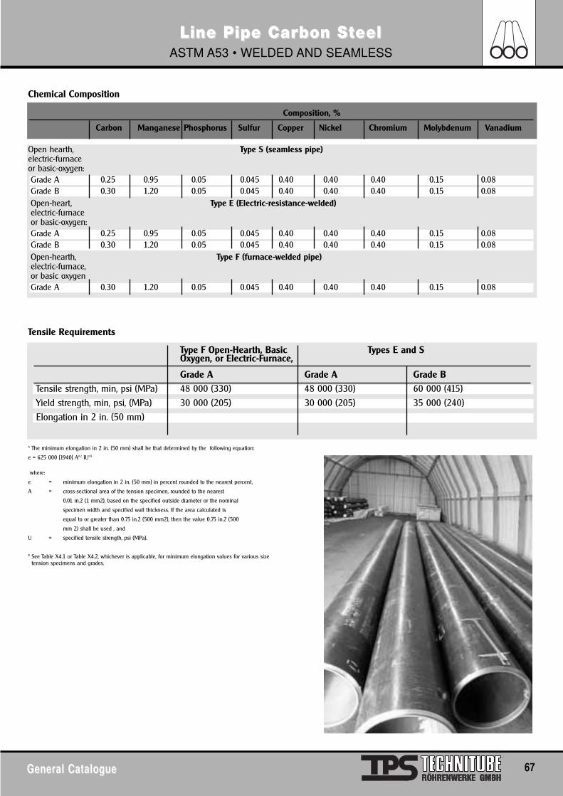
General CatalogueGeneral Catalogue 67
Line Pipe Carbon SLine Pipe Carbon Stteel eel ASTM A53 • WELDED AND SEAMLESS
Chemical Composition
Open hearth, Type S (seamless pipe)electric-furnaceor basic-oxygen:Grade A 0.25 0.95 0.05 0.045 0.40 0.40 0.40 0.15 0.08Grade B 0.30 1.20 0.05 0.045 0.40 0.40 0.40 0.15 0.08Open-heart, Type E (Electric-resistance-welded)electric-furnaceor basic-oxygen:Grade A 0.25 0.95 0.05 0.045 0.40 0.40 0.40 0.15 0.08Grade B 0.30 1.20 0.05 0.045 0.40 0.40 0.40 0.15 0.08Open-hearth, Type F (furnace-welded pipe)electric-furnace,or basic oxygenGrade A 0.30 1.20 0.05 0.045 0.40 0.40 0.40 0.15 0.08
Composition, %
Carbon Manganese Phosphorus Sulfur Copper Nickel Chromium Molybdenum Vanadium
A The minimum elongation in 2 in. (50 mm) shall be that determined by the following equation:
e = 625 000 [1940] A0.2 IU0.9
where:
e = minimum elongation in 2 in. (50 mm) in percent rounded to the nearest percent,
A = cross-sectional area of the tension specimen, rounded to the nearest
0.01 in.2 (1 mm2), based on the specified outside diameter or the nominal
specimen width and specified wall thickness. If the area calculated is
equal to or greater than 0.75 in.2 (500 mm2), then the value 0.75 in.2 (500
mm 2) shall be used , and
U = specified tensile strength, psi (MPa).
B See Table X4.1 or Table X4.2, whichever is applicable, for minimum elongation values for various sizetension specimens and grades.
Tensile Requirements
Type F Open-Hearth, Basic Types E and S Oxygen, or Electric-Furnace,
Grade A Grade A Grade BTensile strength, min, psi (MPa) 48 000 (330) 48 000 (330) 60 000 (415)Yield strength, min, psi, (MPa) 30 000 (205) 30 000 (205) 35 000 (240)Elongation in 2 in. (50 mm)
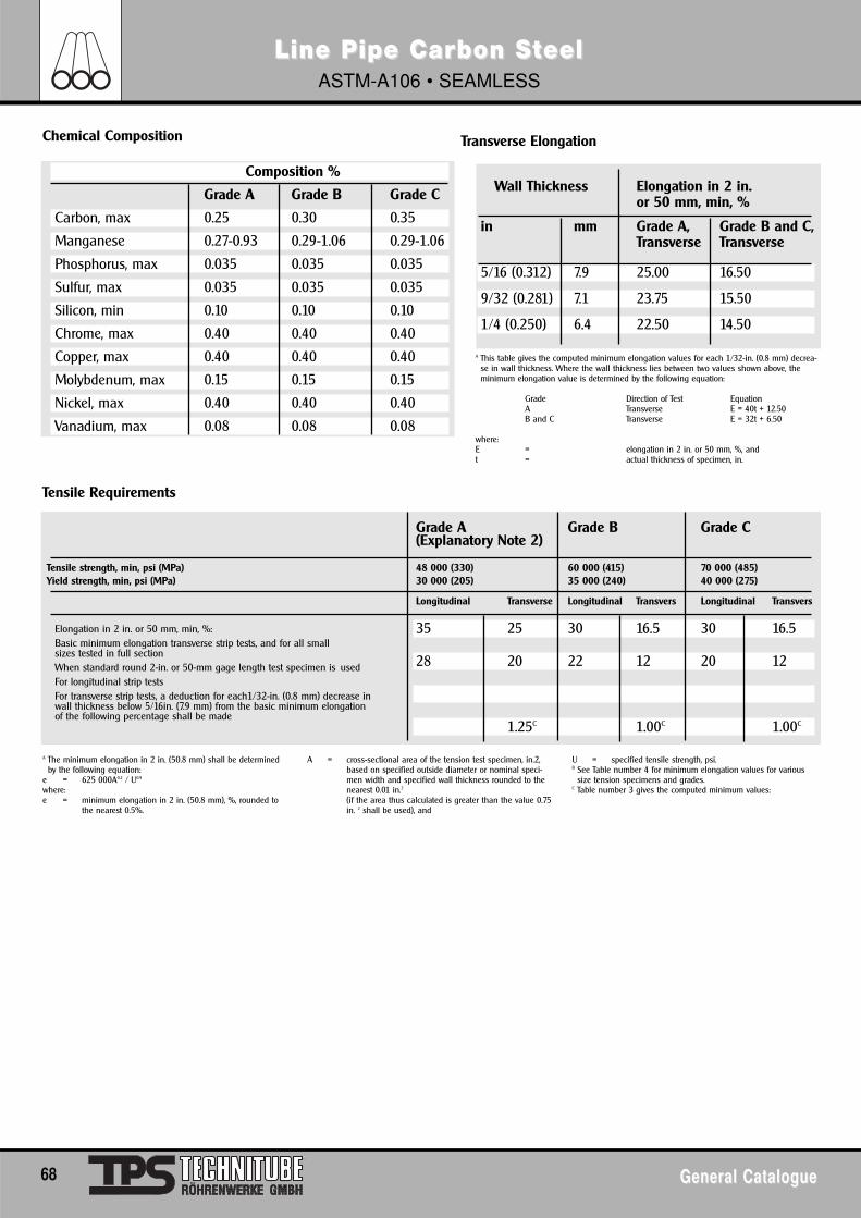
68 General CatalogueGeneral Catalogue
Line Pipe Carbon SLine Pipe Carbon Stteel eel ASTM-A106 • SEAMLESS
Chemical Composition
A This table gives the computed minimum elongation values for each 1/32-in. (0.8 mm) decrea-se in wall thickness. Where the wall thickness lies between two values shown above, theminimum elongation value is determined by the following equation:
Grade Direction of Test EquationA Transverse E = 40t + 12.50B and C Transverse E = 32t + 6.50
where:E = elongation in 2 in. or 50 mm, %, andt = actual thickness of specimen, in.
A The minimum elongation in 2 in. (50.8 mm) shall be determinedby the following equation:
e = 625 000A0.2 / U0.9
where:e = minimum elongation in 2 in. (50.8 mm), %, rounded to
the nearest 0.5%.
A = cross-sectional area of the tension test specimen, in.2,based on specified outside diameter or nominal speci-men width and specified wall thickness rounded to thenearest 0.01 in.2
(if the area thus calculated is greater than the value 0.75 in. 2 shall be used), and
U = specified tensile strength, psi.B See Table number 4 for minimum elongation values for various
size tension specimens and grades.C Table number 3 gives the computed minimum values:
Tensile Requirements
Transverse Elongation
Composition %
Grade A Grade B Grade C
Carbon, max 0.25 0.30 0.35
Manganese 0.27-0.93 0.29-1.06 0.29-1.06
Phosphorus, max 0.035 0.035 0.035
Sulfur, max 0.035 0.035 0.035
Silicon, min 0.10 0.10 0.10
Chrome, max 0.40 0.40 0.40
Copper, max 0.40 0.40 0.40
Molybdenum, max 0.15 0.15 0.15
Nickel, max 0.40 0.40 0.40
Vanadium, max 0.08 0.08 0.08
Wall Thickness Elongation in 2 in. or 50 mm, min, %
in mm Grade A, Grade B and C,Transverse Transverse
5/16 (0.312) 7.9 25.00 16.50
9/32 (0.281) 7.1 23.75 15.50
1/4 (0.250) 6.4 22.50 14.50
Grade A Grade B Grade C(Explanatory Note 2)
Tensile strength, min, psi (MPa) 48 000 (330) 60 000 (415) 70 000 (485)Yield strength, min, psi (MPa) 30 000 (205) 35 000 (240) 40 000 (275)
Longitudinal Transverse Longitudinal Transvers Longitudinal Transvers
35 25 30 16.5 30 16.5
28 20 22 12 20 12
1.25C 1.00C 1.00C
Elongation in 2 in. or 50 mm, min, %:Basic minimum elongation transverse strip tests, and for all small sizes tested in full sectionWhen standard round 2-in. or 50-mm gage length test specimen is usedFor longitudinal strip testsFor transverse strip tests, a deduction for each1/32-in. (0.8 mm) decrease inwall thickness below 5/16in. (7.9 mm) from the basic minimum elongationof the following percentage shall be made
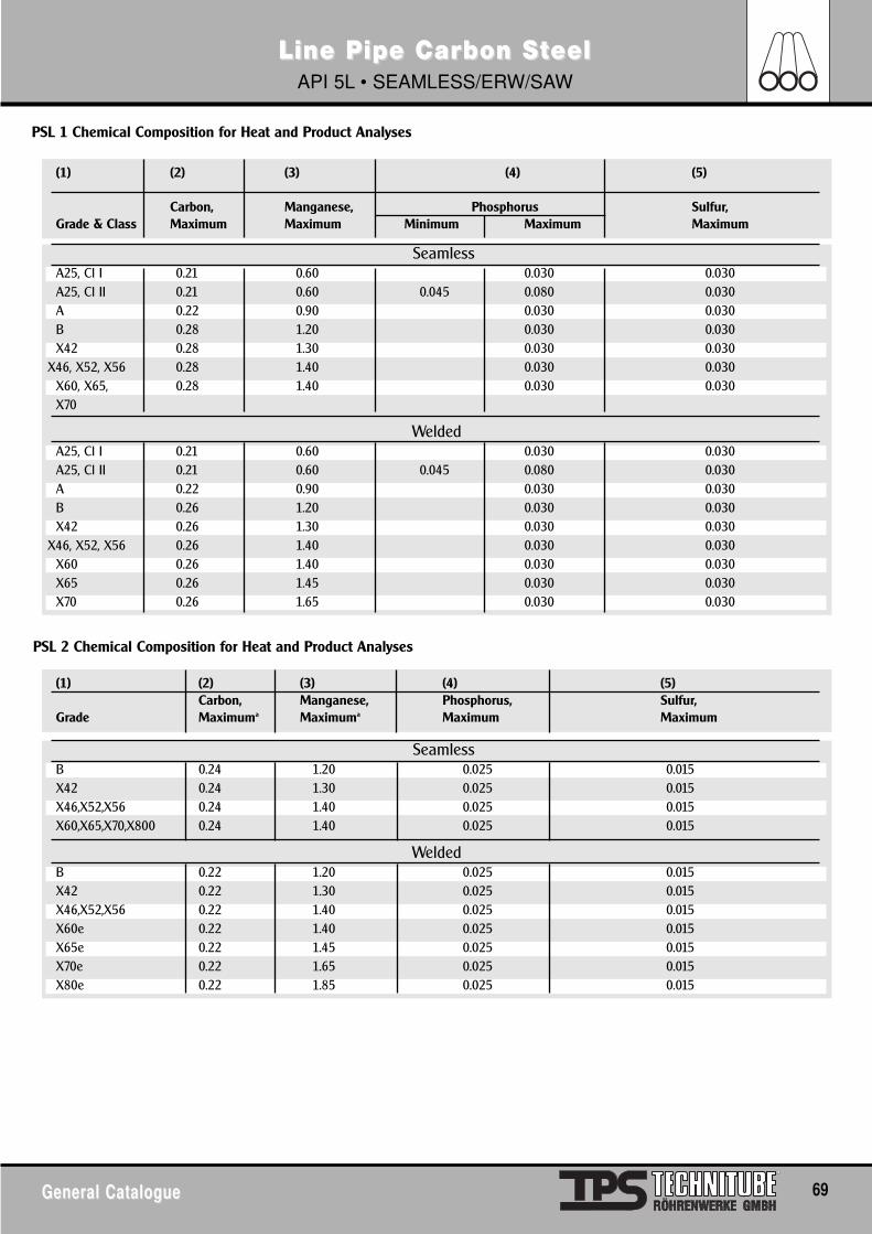
General CatalogueGeneral Catalogue 69
Line Pipe Carbon SLine Pipe Carbon StteeleelAPI 5L • SEAMLESS/ERW/SAW
PSL 1 Chemical Composition for Heat and Product Analyses
SeamlessA25, Cl I 0.21 0.60 0.030 0.030A25, Cl II 0.21 0.60 0.045 0.080 0.030A 0.22 0.90 0.030 0.030B 0.28 1.20 0.030 0.030X42 0.28 1.30 0.030 0.030
X46, X52, X56 0.28 1.40 0.030 0.030X60, X65, 0.28 1.40 0.030 0.030X70
WeldedA25, Cl I 0.21 0.60 0.030 0.030A25, Cl II 0.21 0.60 0.045 0.080 0.030A 0.22 0.90 0.030 0.030B 0.26 1.20 0.030 0.030X42 0.26 1.30 0.030 0.030
X46, X52, X56 0.26 1.40 0.030 0.030X60 0.26 1.40 0.030 0.030X65 0.26 1.45 0.030 0.030X70 0.26 1.65 0.030 0.030
(1) (2) (3) (4) (5)
Carbon, Manganese, Phosphorus Sulfur,Grade & Class Maximum Maximum Minimum Maximum Maximum
SeamlessB 0.24 1.20 0.025 0.015X42 0.24 1.30 0.025 0.015X46,X52,X56 0.24 1.40 0.025 0.015X60,X65,X70,X800 0.24 1.40 0.025 0.015
WeldedB 0.22 1.20 0.025 0.015X42 0.22 1.30 0.025 0.015X46,X52,X56 0.22 1.40 0.025 0.015X60e 0.22 1.40 0.025 0.015X65e 0.22 1.45 0.025 0.015X70e 0.22 1.65 0.025 0.015X80e 0.22 1.85 0.025 0.015
(1) (2) (3) (4) (5)Carbon, Manganese, Phosphorus, Sulfur,
Grade Maximuma Maximuma Maximum Maximum
PSL 2 Chemical Composition for Heat and Product Analyses
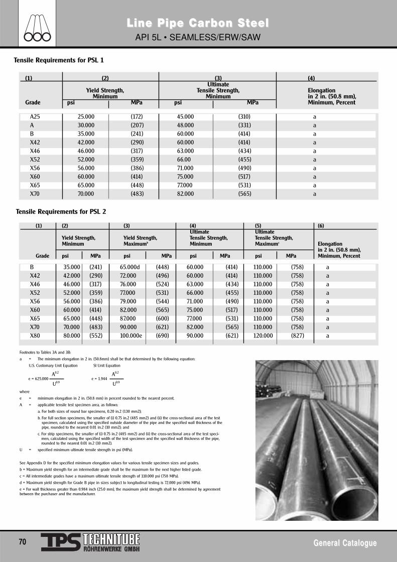
70 General CatalogueGeneral Catalogue
Line Pipe Carbon SLine Pipe Carbon StteeleelAPI 5L • SEAMLESS/ERW/SAW
Tensile Requirements for PSL 1
Tensile Requirements for PSL 2
A25 25.000 (172) 45.000 (310) aA 30.000 (207) 48.000 (331) aB 35.000 (241) 60.000 (414) aX42 42.000 (290) 60.000 (414) aX46 46.000 (317) 63.000 (434) aX52 52.000 (359) 66.00 (455) aX56 56.000 (386) 71.000 (490) aX60 60.000 (414) 75.000 (517) aX65 65.000 (448) 77.000 (531) aX70 70.000 (483) 82.000 (565) a
(1) (2) (3) (4)Ultimate
Yield Strength, Tensile Strength, ElongationMinimum Minimum in 2 in. (50.8 mm),
Grade psi MPa psi MPa Minimum, Percent
Footnotes to Tables 3A and 3B:
a = The minimum elongation in 2 in. (50.8mm) shall be that determined by the following equation:
U.S. Customary Unit Equation SI Unit Equation
B 35.000 (241) 65.000d (448) 60.000 (414) 110.000 (758) aX42 42.000 (290) 72.000 (496) 60.000 (414) 110.000 (758) aX46 46.000 (317) 76.000 (524) 63.000 (434) 110.000 (758) aX52 52.000 (359) 77.000 (531) 66.000 (455) 110.000 (758) aX56 56.000 (386) 79.000 (544) 71.000 (490) 110.000 (758) aX60 60.000 (414) 82.000 (565) 75.000 (517) 110.000 (758) aX65 65.000 (448) 87.000 (600) 77.000 (531) 110.000 (758) aX70 70.000 (483) 90.000 (621) 82.000 (565) 110.000 (758) aX80 80.000 (552) 100.000e (690) 90.000 (621) 120.000 (827) a
(1) (2) (3) (4) (5) (6)Ultimate Ultimate
Yield Strength, Yield Strength, Tensile Strength, Tensile Strength,Minimum Maximumb Minimum Maximumc Elongation
in 2 in. (50.8 mm),Grade psi MPa psi MPa psi MPa psi MPa Minimum, Percent
e = 625.000 e = 1.944 U0.9
A0.2
U0.9
A0.2
where
e = minimum elongation in 2 in. (50.8 mm) in percent rounded to the nearest percent.
A = applicable tensile test specimen area, as follows:
a. For both sizes of round bar specimens, 0.20 in.2 (130 mm2);
b. For full section specimens, the smaller of (i) 0.75 in.2 (485 mm2) and (ii) the cross-sectional area of the testspecimen, calculated using the specified outside diameter of the pipe and the specified wall thickness of thepipe, rounded to the nearest 0.01 in.2 (10 mm2); and
c. For strip specimens, the smaller of (i) 0.75 in.2 (485 mm2) and (ii) the cross-sectional area of the test speci-men, calculated using the specified width of the test specimen and the specified wall thickness of the pipe,rounded to the nearest 0.01 in.2 (10 mm2).
U = specified minimum ultimate tensile strength in psi (MPa).
See Appendix D for the specified minimum elongation values for various tensile specimen sizes and grades.
b = Maximum yield strength for an intermediate grade shall be the maximum for the next higher listed grade.
c = All intermediate grades have a maximum ultimate tensile strength of 110.000 psi (758 MPa).
d = Maximum yield strength for Grade B pipe in sizes subject to longitudinal testing is 72.000 psi (496 MPa).
e = For wall thickness greater than 0.984 inch (25.0 mm), the maximum yield strength shall be determined by agreementbetween the purchaser and the manufacturer.
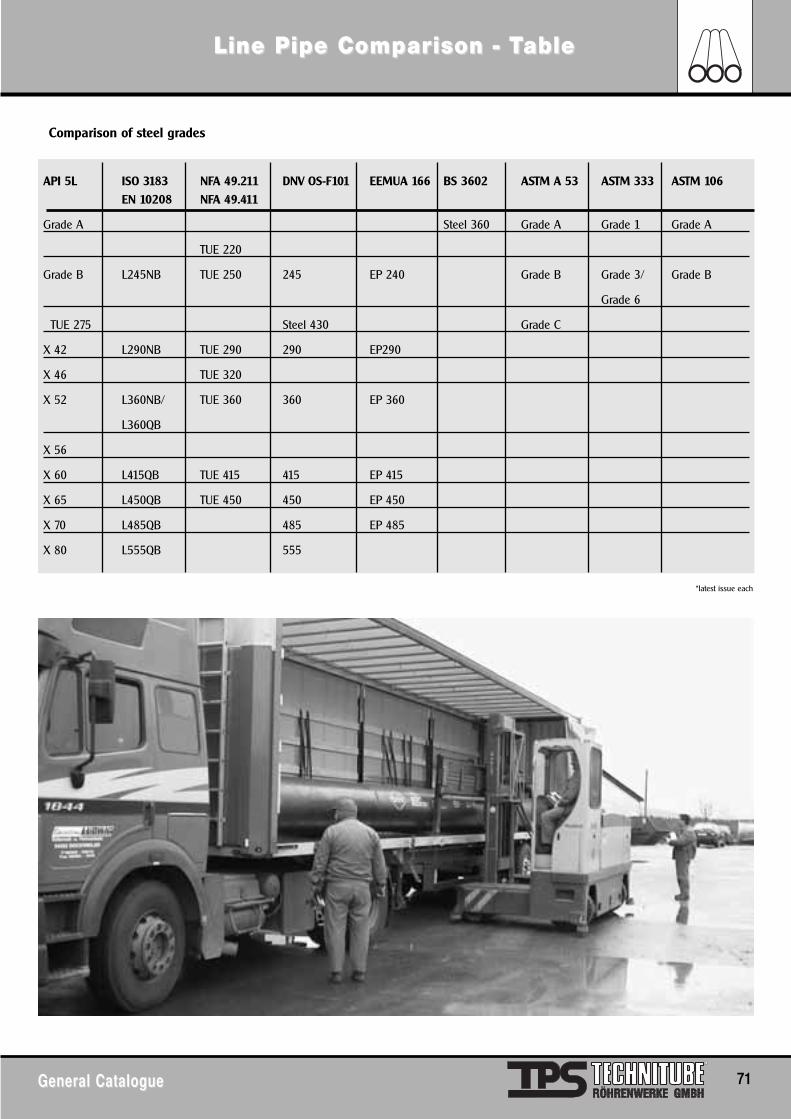
General CatalogueGeneral Catalogue 71
Line Pipe ComLine Pipe Comparparison - Tison - Tableable
Comparison of steel grades
API 5L ISO 3183 NFA 49.211 DNV OS-F101 EEMUA 166 BS 3602 ASTM A 53 ASTM 333 ASTM 106
EN 10208 NFA 49.411
Grade A Steel 360 Grade A Grade 1 Grade A
TUE 220
Grade B L245NB TUE 250 245 EP 240 Grade B Grade 3/ Grade B
Grade 6
TUE 275 Steel 430 Grade C
X 42 L290NB TUE 290 290 EP290
X 46 TUE 320
X 52 L360NB/ TUE 360 360 EP 360
L360QB
X 56
X 60 L415QB TUE 415 415 EP 415
X 65 L450QB TUE 450 450 EP 450
X 70 L485QB 485 EP 485
X 80 L555QB 555
*latest issue each
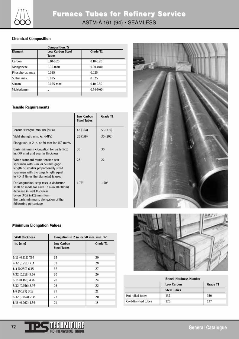
72 General CatalogueGeneral Catalogue
FFururnace Tnace Tubes fubes for Ror Refef inerinery Sery ServiceviceASTM-A 161 (94) • SEAMLESS
Chemical Composition
Tensile Requirements
Composition. %Element Low Carbon Steel Grade T1
Tubes
Carbon 0.10-0.20 0.10-0.20
Manganese 0.30-0.80 0.30-0.80
Phosphorus. max. 0.035 0.025
Sulfur. max. 0.035 0.025
Silicon 0.025 max 0.10-0.50
Molybdenum ... 0.44-0.65
Low Carbon Grade T1Steel Tubes
Tensile strength. min. ksi (MPa) 47 (324) 55 (379)
Yield strength. min. ksi (MPa) 26 (179) 30 (207)
Elongation in 2 in. or 50 mm (or 4D) min%
Basic minimum elongation for walls 5/16 35 30in. (7.9 mm) and over in thickness
When standard round tension test 28 22specimen with 2-in. or 50-mm gagelength or smaller proportionally sizedspecimen with the gage length equalto 4D (4 times the diameter) is used
For longitudinal strip tests. a deduction 1.75A 1.50A
shall be made for each 1/32-in. (0.80mm)decrease in wall thickness below 3/16 in.(7.9mm) fromthe basic minimum. elongation of thefollowning percentage
Minimum Elongation Values
Wall thickness Elongation in 2 in. or 50 mm. min. %A
in. (mm) Low Carbon Grade T1Steel Tubes
5/16 (0.312) 7.94 35 30
9/32 (0.281) 7.14 33 28
1/4 (0.250) 6.35 32 27
7/32 (0.219) 5.56 30 26
3/16 (0.188) 4.76 28 24
5/32 (0.156) 3.97 26 22
1/8 (0.125) 3.18 25 21
3/32 (0.094) 2.38 23 20
1/16 (0.062) 1.59 21 18
Brinell Hardness Number
Low Carbon Grade T1
Steel Tubes
Hot-rolled tubes 137 150
Cold-finished tubes 125 137
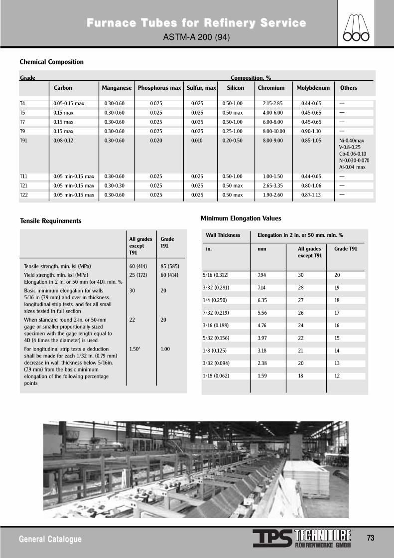
General CatalogueGeneral Catalogue 73
FFururnace Tnace Tubes fubes for Ror Refef inerinery Sery ServiceviceASTM-A 200 (94)
Chemical Composition
T4 0.05-0.15 max 0.30-0.60 0.025 0.025 0.50-1.00 2.15-2.85 0.44-0.65 —
T5 0.15 max 0.30-0.60 0.025 0.025 0.50 max 4.00-6.00 0.45-0.65 —
T7 0.15 max 0.30-0.60 0.025 0.025 0.50-1.00 6.00-8.00 0.45-0.65 —
T9 0.15 max 0.30-0.60 0.025 0.025 0.25-1.00 8.00-10.00 0.90-1.10 —
T91 0.08-0.12 0.30-0.60 0.020 0.010 0.20-0.50 8.00-9.00 0.85-1.05 Ni-0.40maxV-0.8-0.25Cb-0.06-0.10N-0.030-0.070Al-0.04 max
T11 0.05 min-0.15 max 0.30-0.60 0.025 0.025 0.50-1.00 1.00-1.50 0.44-0.65 —
T21 0.05 min-0.15 max 0.30-0.30 0.025 0.025 0.50 max 2.65-3.35 0.80-1.06 —
T22 0.05 min-0.15 max 0.30-0.60 0.025 0.025 0.50 max 1.90-2.60 0.87-1.13 —
Grade Composition, %
Carbon Manganese Phosphorus max Sulfur, max Silicon Chromium Molybdenum Others
Tensile Requirements
All grades Gradeexcept T91T91
Tensile strength. min. lsi (MPa) 60 (414) 85 (585)
Yield strength. min. ksi (MPa) 25 (172) 60 (414)Elongation in 2 in. or 50 mm (or 4D). min. %
Basic minimum elongation for walls 30 205/16 in (7.9 mm) and over in thickness.longitudinal strip tests. and for all smallsizes tested in full section
When standard round 2-in. or 50-mm 22 20gage or smaller proportionally sizedspecimen with the gage length equal to4D (4 times the diameter) is used.
For longitudinal strip tests a deduction 1.50A 1.00shall be made for each 1/32 in. (0.79 mm)decrease in wall thickness below 5/16in. (7.9 mm) from the basic minimumelongation of the following percentage points
Minimum Elongation Values
Wall Thickness Elongation in 2 in. or 50 mm. min. %
in. mm All grades Grade T91except T91
5/16 (0.312) 7.94 30 20
3/32 (0.281) 7.14 28 19
1/4 (0.250) 6.35 27 18
7/32 (0.219) 5.56 26 17
3/16 (0.188) 4.76 24 16
5/32 (0.156) 3.97 22 15
1/8 (0.125) 3.18 21 14
3/32 (0.094) 2.38 20 13
1/18 (0.062) 1.59 18 12
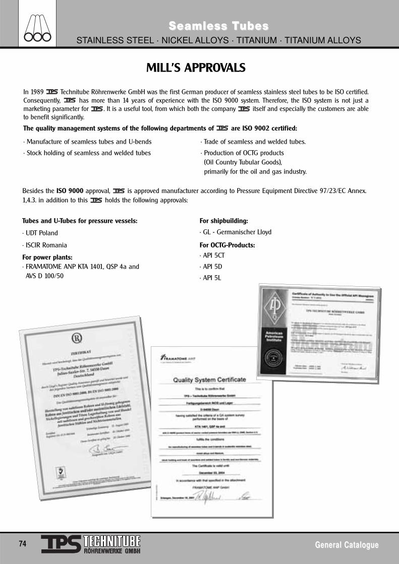
74 General CatalogueGeneral Catalogue
Seamless TSeamless TubesubesSTAINLESS STEEL · NICKEL ALLOYS · TITANIUM · TITANIUM ALLOYS
In 1989 Technitube Röhrenwerke GmbH was the first German producer of seamless stainless steel tubes to be ISO certified.Consequently, has more than 14 years of experience with the ISO 9000 system. Therefore, the ISO system is not just amarketing parameter for . It is a useful tool, from which both the company itself and especially the customers are ableto benefit significantly.
The quality management systems of the following departments of are ISO 9002 certified:
• Manufacture of seamless tubes and U-bends
• Stock holding of seamless and welded tubes
• Trade of seamless and welded tubes.
• Production of OCTG products (Oil Country Tubular Goods), primarily for the oil and gas industry.
Besides the ISO 9000 approval, is approved manufacturer according to Pressure Equipment Directive 97/23/EC Annex.1,4.3. in addition to this holds the following approvals:
Tubes and U-Tubes for pressure vessels:
• UDT Poland
• ISCIR Romania
For power plants: • FRAMATOME ANP KTA 1401, QSP 4a and AVS D 100/50
For shipbuilding:
• GL - Germanischer Lloyd
For OCTG-Products:
• API 5CT
• API 5D
• API 5L
MILL’S APPROVALS
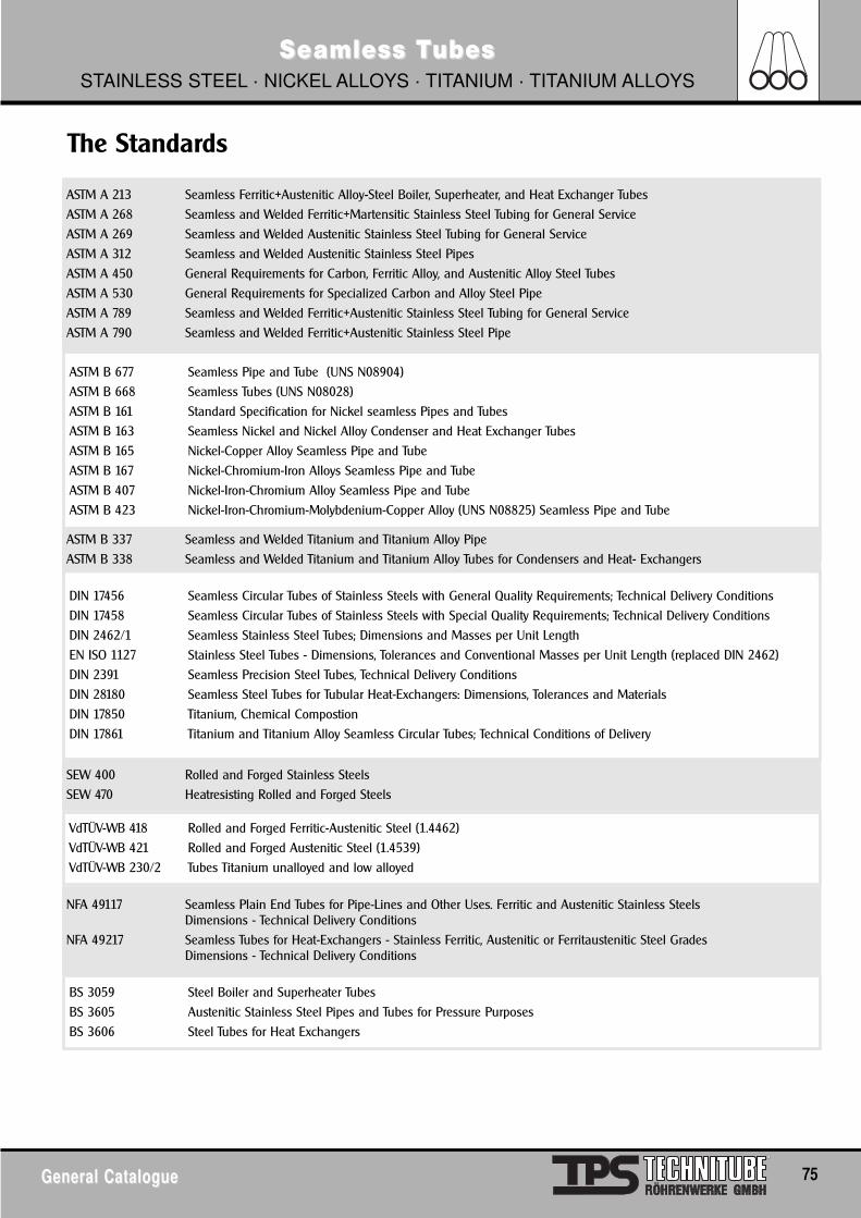
General CatalogueGeneral Catalogue 75
Seamless TSeamless TubesubesSTAINLESS STEEL · NICKEL ALLOYS · TITANIUM · TITANIUM ALLOYS
The Standards
ASTM A 213 Seamless Ferritic+Austenitic Alloy-Steel Boiler, Superheater, and Heat Exchanger Tubes
ASTM A 268 Seamless and Welded Ferritic+Martensitic Stainless Steel Tubing for General Service
ASTM A 269 Seamless and Welded Austenitic Stainless Steel Tubing for General Service
ASTM A 312 Seamless and Welded Austenitic Stainless Steel Pipes
ASTM A 450 General Requirements for Carbon, Ferritic Alloy, and Austenitic Alloy Steel Tubes
ASTM A 530 General Requirements for Specialized Carbon and Alloy Steel Pipe
ASTM A 789 Seamless and Welded Ferritic+Austenitic Stainless Steel Tubing for General Service
ASTM A 790 Seamless and Welded Ferritic+Austenitic Stainless Steel Pipe
ASTM B 677 Seamless Pipe and Tube (UNS N08904)
ASTM B 668 Seamless Tubes (UNS N08028)
ASTM B 161 Standard Specification for Nickel seamless Pipes and Tubes
ASTM B 163 Seamless Nickel and Nickel Alloy Condenser and Heat Exchanger Tubes
ASTM B 165 Nickel-Copper Alloy Seamless Pipe and Tube
ASTM B 167 Nickel-Chromium-Iron Alloys Seamless Pipe and Tube
ASTM B 407 Nickel-Iron-Chromium Alloy Seamless Pipe and Tube
ASTM B 423 Nickel-Iron-Chromium-Molybdenium-Copper Alloy (UNS N08825) Seamless Pipe and Tube
ASTM B 337 Seamless and Welded Titanium and Titanium Alloy Pipe
ASTM B 338 Seamless and Welded Titanium and Titanium Alloy Tubes for Condensers and Heat- Exchangers
DIN 17456 Seamless Circular Tubes of Stainless Steels with General Quality Requirements; Technical Delivery Conditions
DIN 17458 Seamless Circular Tubes of Stainless Steels with Special Quality Requirements; Technical Delivery Conditions
DIN 2462/1 Seamless Stainless Steel Tubes; Dimensions and Masses per Unit Length
EN ISO 1127 Stainless Steel Tubes - Dimensions, Tolerances and Conventional Masses per Unit Length (replaced DIN 2462)
DIN 2391 Seamless Precision Steel Tubes, Technical Delivery Conditions
DIN 28180 Seamless Steel Tubes for Tubular Heat-Exchangers: Dimensions, Tolerances and Materials
DIN 17850 Titanium, Chemical Compostion
DIN 17861 Titanium and Titanium Alloy Seamless Circular Tubes; Technical Conditions of Delivery
SEW 400 Rolled and Forged Stainless Steels
SEW 470 Heatresisting Rolled and Forged Steels
VdTÜV-WB 418 Rolled and Forged Ferritic-Austenitic Steel (1.4462)
VdTÜV-WB 421 Rolled and Forged Austenitic Steel (1.4539)
VdTÜV-WB 230/2 Tubes Titanium unalloyed and low alloyed
NFA 49117 Seamless Plain End Tubes for Pipe-Lines and Other Uses. Ferritic and Austenitic Stainless SteelsDimensions - Technical Delivery Conditions
NFA 49217 Seamless Tubes for Heat-Exchangers - Stainless Ferritic, Austenitic or Ferritaustenitic Steel GradesDimensions - Technical Delivery Conditions
BS 3059 Steel Boiler and Superheater Tubes
BS 3605 Austenitic Stainless Steel Pipes and Tubes for Pressure Purposes
BS 3606 Steel Tubes for Heat Exchangers
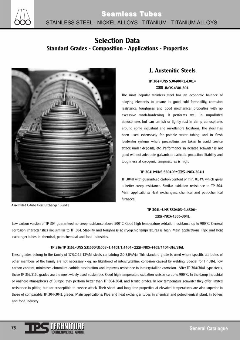
76 General CatalogueGeneral Catalogue
Seamless TSeamless TubesubesSTAINLESS STEEL · NICKEL ALLOYS · TITANIUM · TITANIUM ALLOYS
Selection DataStandard Grades - Composition - Applications - Properties
1. Austenitic Steels
TP 304=UNS S30400=1.4301=
-INOX-4301-304
The most popular stainless steel has an economic balance of
alloying elements to ensure its good cold formability, corrosion
resistance, toughness and good mechanical properties with no
excessive work-hardening. It performs well in unpolluted
atmospheres but can tarnish or lightly rust in damp atmospheres
around some industrial and on/offshore locations. The steel has
been used extensively for potable water tubing and in fresh
feedwater systems where precautions are taken to avoid crevice
attack under deposits, etc. Performance in aerated seawater is not
good without adequate galvanic or cathodic protection. Stability and
toughness at cryogenic temperatures is high.
TP 304H=UNS S30409= -INOX-304H
TP 304H with guaranteed carbon content of min. 0,04% which gives
a better creep resistance. Similar oxidation resistance to TP 304.
Main applications: Heat exchangers, chemical and petrochemical
furnaces.
TP 304L=UNS S30403=1.4306=
-INOX-4306-304L
Low carbon version of TP 304 guaranteed no creep resistance above 500°C. Good high temperature oxidation resistance up to 900°C. General
corrosion characteristics are similar to TP 304. Stability and toughness at cryogenic temperatures is high. Main applications: Pipe and heat
exchanger tubes in chemical, petrochemical and food industries.
TP 316/TP 316L=UNS S31600/31603=1.4401/1.4404= -INOX-4401/4404-316/316L
These grades belong to the family of 17%Cr12-13%Ni steels containing 2,0-3,0%Mo. This standard grade is used where specific attributes of
other members of the family are not necessary - eg. no likelihood of intercrystalline corrosion caused by welding. Special for TP 316L, low
carbon content, minimizes chromium carbide preciptation and improves resistance to intercrystalline corrosion. After TP 304/304L type steels,
these TP 316/316L grades are the most widely used austenitics. Good high temperature oxidation resistance up to 900°C. In the damp industrial
or onshore atmospheres of Europe, they perform better than TP 304/304L and ferritic grades. In low temperature seawater they offer limited
resistance to pitting but are susceptible to crevice attack. Their short- and long-time properties at elevated temperatures are also superior to
those of comparable TP 304/304L grades. Main applications: Pipe and heat exchanger tubes in chemical and petrochemical plant, in boilers
and food industry.
Assembled U-tube Heat Exchanger Bundle

General CatalogueGeneral Catalogue 77
Seamless TSeamless TubesubesSTAINLESS STEEL · NICKEL ALLOYS · TITANIUM · TITANIUM ALLOYS
TP 316H=UNS S31609= -INOX-316H
This grade with guaranteed carbon content of min. 0,04% enhances strength at elevated temperatures. Similar oxidation resistance to TP 316.
Main applications: Heat exchangers, furnaces, chemical and petrochemical plant.
Selection DataStandard Grades - Composition - Applications - Properties
78 General CatalogueGeneral Catalogue
Seamless TSeamless TubesubesSTAINLESS STEEL · NICKEL ALLOYS · TITANIUM · TITANIUM ALLOYS
Selection DataStandard Grades - Composition - Applications - Properties
TP 321=UNS S32100=1.4541= -INOX-4541-321
High carbon steels prone more to intercrystalline attack in weld zones and slower cooling sections. These steel avoids such attacks throughits stabilization with Ti. The corrosion behaviour of this alloy in natural environments is very similar to the TP 304/304L alloys. Architecturally,it may not be adequate for near-industrial or onshore locations in Europe. Satisfactory in many low-chloride waters, it is prone to pitting orcrevice corrosion in seawater. Water treatment, galvanic protection and deaeration can influence the performance.
TP 321H=UNS S32100=1.4878= -INOX-4878-321H
This is the high carbon version of TP 321 which ensures greater creep resistance. Behaves much the same as TP 321 in oxidation resistance.Main applications: Heat exchangers, furnaces, boilers in chemical and petrochemical plant.
TP 316Ti=UNS S31635=1.4571= -INOX-4571-316Ti
This is one of the family of 17%Cr12-13%Ni steels containing Mo of 2,0-2,4% stabilized with Ti which minimizes chromium carbide precipitationand improves resistance to intergranular corrosion. In the damp industrial or coastal atmospheres of Europe, they perform better than TP304/304L and ferritic grades. In low temperature seawater they offer limited resistance to pitting but are susceptible to crevice attack. Theirshort- and long-time properties at elevated temperatures are also superior to those of comparable TP 304/304L grades.
2. Super-Austenitic Steels
TP 904L=UNS N08904=1.4539= -Technichromo 904L
This high-alloy austenitic is very resistant to attack from diluted sulphuric acid, phosphoric acid and acetic acid. It resists pitting in neutralchloride solutions. Its resistance to stress corrosion cracking in some hot chlorides is much superior to that of the lower nickel austenites. Thissteel has good formability and weldability. This material is present in all common standards like ASTM, DIN, BS and NFA, however with somedifferences. Design stresses up to 370°C are included in ASME II.
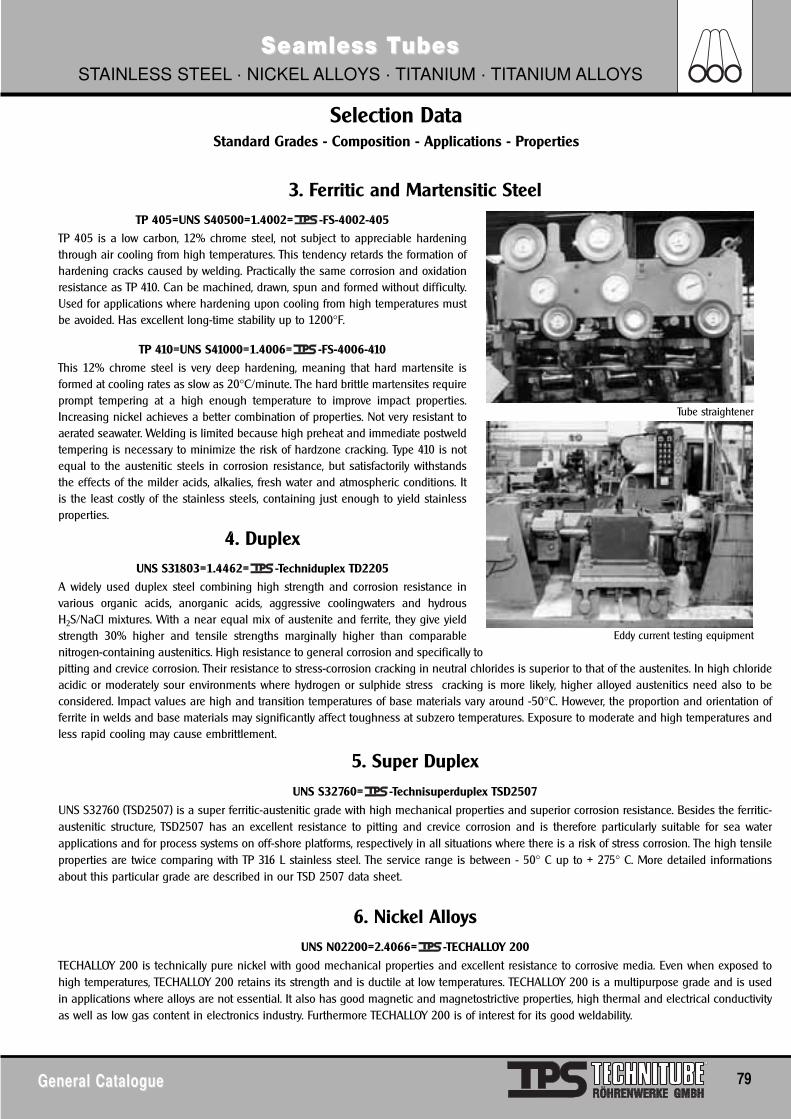
General CatalogueGeneral Catalogue 79
Seamless TSeamless TubesubesSTAINLESS STEEL · NICKEL ALLOYS · TITANIUM · TITANIUM ALLOYS
Selection DataStandard Grades - Composition - Applications - Properties
3. Ferritic and Martensitic SteelTP 405=UNS S40500=1.4002= -FS-4002-405
TP 405 is a low carbon, 12% chrome steel, not subject to appreciable hardeningthrough air cooling from high temperatures. This tendency retards the formation ofhardening cracks caused by welding. Practically the same corrosion and oxidationresistance as TP 410. Can be machined, drawn, spun and formed without difficulty.Used for applications where hardening upon cooling from high temperatures mustbe avoided. Has excellent long-time stability up to 1200°F.
TP 410=UNS S41000=1.4006= -FS-4006-410
This 12% chrome steel is very deep hardening, meaning that hard martensite isformed at cooling rates as slow as 20°C/minute. The hard brittle martensites requireprompt tempering at a high enough temperature to improve impact properties.Increasing nickel achieves a better combination of properties. Not very resistant toaerated seawater. Welding is limited because high preheat and immediate postweldtempering is necessary to minimize the risk of hardzone cracking. Type 410 is notequal to the austenitic steels in corrosion resistance, but satisfactorily withstandsthe effects of the milder acids, alkalies, fresh water and atmospheric conditions. Itis the least costly of the stainless steels, containing just enough to yield stainlessproperties.
4. DuplexUNS S31803=1.4462= -Techniduplex TD2205
A widely used duplex steel combining high strength and corrosion resistance invarious organic acids, anorganic acids, aggressive coolingwaters and hydrousH2S/NaCl mixtures. With a near equal mix of austenite and ferrite, they give yieldstrength 30% higher and tensile strengths marginally higher than comparablenitrogen-containing austenitics. High resistance to general corrosion and specifically topitting and crevice corrosion. Their resistance to stress-corrosion cracking in neutral chlorides is superior to that of the austenites. In high chlorideacidic or moderately sour environments where hydrogen or sulphide stress cracking is more likely, higher alloyed austenitics need also to beconsidered. Impact values are high and transition temperatures of base materials vary around -50°C. However, the proportion and orientation offerrite in welds and base materials may significantly affect toughness at subzero temperatures. Exposure to moderate and high temperatures andless rapid cooling may cause embrittlement.
5. Super Duplex
UNS S32760= -Technisuperduplex TSD2507
UNS S32760 (TSD2507) is a super ferritic-austenitic grade with high mechanical properties and superior corrosion resistance. Besides the ferritic-austenitic structure, TSD2507 has an excellent resistance to pitting and crevice corrosion and is therefore particularly suitable for sea waterapplications and for process systems on off-shore platforms, respectively in all situations where there is a risk of stress corrosion. The high tensileproperties are twice comparing with TP 316 L stainless steel. The service range is between - 50° C up to + 275° C. More detailed informationsabout this particular grade are described in our TSD 2507 data sheet.
6. Nickel AlloysUNS N02200=2.4066= -TECHALLOY 200
TECHALLOY 200 is technically pure nickel with good mechanical properties and excellent resistance to corrosive media. Even when exposed tohigh temperatures, TECHALLOY 200 retains its strength and is ductile at low temperatures. TECHALLOY 200 is a multipurpose grade and is usedin applications where alloys are not essential. It also has good magnetic and magnetostrictive properties, high thermal and electrical conductivityas well as low gas content in electronics industry. Furthermore TECHALLOY 200 is of interest for its good weldability.
Tube straightener
Eddy current testing equipment
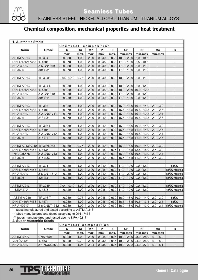
80 General CatalogueGeneral Catalogue
Seamless TSeamless TubesubesSTAINLESS STEEL · NICKEL ALLOYS · TITANIUM · TITANIUM ALLOYS
Chemical composition, mechanical properties and heat treatment
1. Austenitic SteelsC h e m i c a l c o m p o s i t i o n
Norm Grade C Si Mn P S Cr Ni Mo Timax. max. max. max. max. min-max min-max min-max
ASTM A 213 TP 304 0,080 1,00 2,00 0,040 0,030 18,0 - 20,0 8,0 - 10,5 - -DIN 17456/17458 1. 4301 0,070 1,00 2,00 0,045 0,030 17,0 - 19,0 8,5 - 10,5 - -NF A 49217 Z 6 CN1809 0,080 1,00 2,00 0,040 0,030 17,0 - 20,0 8,0 - 11,0 - -BS 3606 304 S31 0,070 1,00 2,00 0,040 0,030 17,0 - 19,0 8,0 - 11,0 - -
ASTM A 213 TP 304H 0,04 - 0,10 0,75 2,00 0,040 0,030 18,0 - 20,0 8,0 - 11,0 - -
ASTM A 213 TP 304 L 0,030 1,00 2,00 0,040 0,030 18,0 - 20,0 8,0 - 12,0 - -DIN 17456/17458 1. 4306 0,030 1,00 2,00 0,045 0,030 18,0 - 20,0 10,0 - 12,5 - -NF A 49217 Z 2 CN1810 0,030 1,00 2,00 0,040 0,030 17,0 - 20,0 9,0 - 12,0 - -BS 3606 304 S11 0,030 1,00 2,00 0,040 0,030 17,0 - 19,0 9,0 - 12,0 - -
ASTM A 213 TP 316 0,080 1,00 2,00 0,040 0,030 16,0 - 18,0 10,0 - 14,0 2,0 - 3,0 -DIN 17456/17458 1. 4401 0,070 1,00 2,00 0,045 0,030 16,5 - 18,5 10,5 - 13,5 2,0 - 2,5 -NF A 49217 Z 2 CND1711 0,070 1,00 2,00 0,040 0,030 16,0 - 18,0 10,0 - 12,5 2,0 - 2,4 -BS 3606 316 S31 0,070 1,00 2,00 0,040 0,030 16,5 - 18,5 10,5 - 13,5 2,0 - 2,5 -
ASTM A 213 TP 316 L 0,030 1,00 2,00 0,040 0,030 16,0 - 18,0 10,0 - 14,0 2,0 - 3,0 -DIN 17456/17458 1. 4404 0,030 1,00 2,00 0,045 0,030 16,5 - 18,5 11,0 - 14,0 2,0 - 2,5 -NF A 49217 Z 2 CND1712 0,030 1,00 2,00 0,040 0,030 16,0 - 18,0 10,5 - 13,0 2,0 - 2,4 -BS 3606 316 S11 0,030 1,00 2,00 0,040 0,030 16,5 - 18,5 11,0 - 14,0 2,0 - 2,5 -
ASTM A213/A240 TP 316L-Mo 0,030 0,75 2,00 0,040 0,030 16,0 - 18,0 10,0 - 14,0 2,0 - 3,0 -DIN 17456/17458 1. 4435 0,030 1,00 2,00 0,045 0,025 17,0 - 18,5 12,5 - 15,0 2,5 - 3,0 -*NF A 35575 Z 2 CND1713 0,030 1,00 2,00 0,040 0,030 16,0 - 18,0 10,5 - 13,0 2,0 - 2,4 -BS 3606 316 S33 0,030 1,00 2,00 0,040 0,030 16,5 - 18,5 11,0 - 14,0 2,5 - 3,0 -
ASTM A 213 TP 321 0,080 1,00 2,00 0,040 0,030 17,0 - 19,0 9,0 - 12,0 - ����
DIN 17456/17458 1. 4541 0,080 1,00 2,00 0,045 0,030 17,0 - 19,0 9,0 - 12,0 - ���� ������
NF A 49217 Z 6 CNT1810 0,080 1,00 2,00 0,040 0,030 17,0 - 20,0 9,0 - 12,0 - ���� ������
BS 3606 321 S31 0,080 1,00 2,00 0,040 0,030 17,0 - 19,0 9,0 - 12,0 - ���� ������
ASTM A 213 TP 321H 0,04 - 0,10 1,00 2,00 0,040 0,030 17,0 - 19,0 9,0 - 13,0 - ���� ������
**SEW 470 1. 4878 0,120 1,00 2,00 0,045 0,030 17,0 - 19,0 9,0 - 12,0 - ���� ������
*ASTM A 240 TP 316 Ti 0,080 0,75 2,00 0,045 0,030 16,0 - 18,0 10,0 - 14,0 2,0 - 3,0 ����
DIN 17456/17458 1. 4571 0,080 1,00 2,00 0,045 0,030 16,5 - 18,5 10,5 - 13,5 2,0 - 2,5 ����
NF A 49217 Z 6 CNDT1712 0,080 1,00 2,00 0,040 0,030 16,0 - 18,0 10,5 - 13,0 2,0 - 2,4 ���� ������
* tubes manufactured and tested according to ASTM A 213** tubes manufactured and tested according to DIN 17456
2. Super-Austenitic SteelsC h e m i c a l c o m p o s i t i o n
Norm Grade C Si Mn P S Cr Ni Mo Timax. max. max. max. max. min-max min-max min-max
ASTM B 677 UNS 8904 0,020 1,00 2,00 0,045 0,035 19,0 - 23,0 23,0 - 28,0 4,0 - 5,0 -VDTÜV 421 1. 4539 0,020 0,70 2,00 0,030 0,015 19,0 - 21,0 24,0 - 26,0 4,0 - 5,0 -NF A 49217 Z 1 NCDU25.2 0,020 1,05 2,04 0,035 0,025 19,0 - 22,2 24,0 - 27,2 4,0 - 5,1 -
*** tubes manufactured and tested acc. to NFA 49217
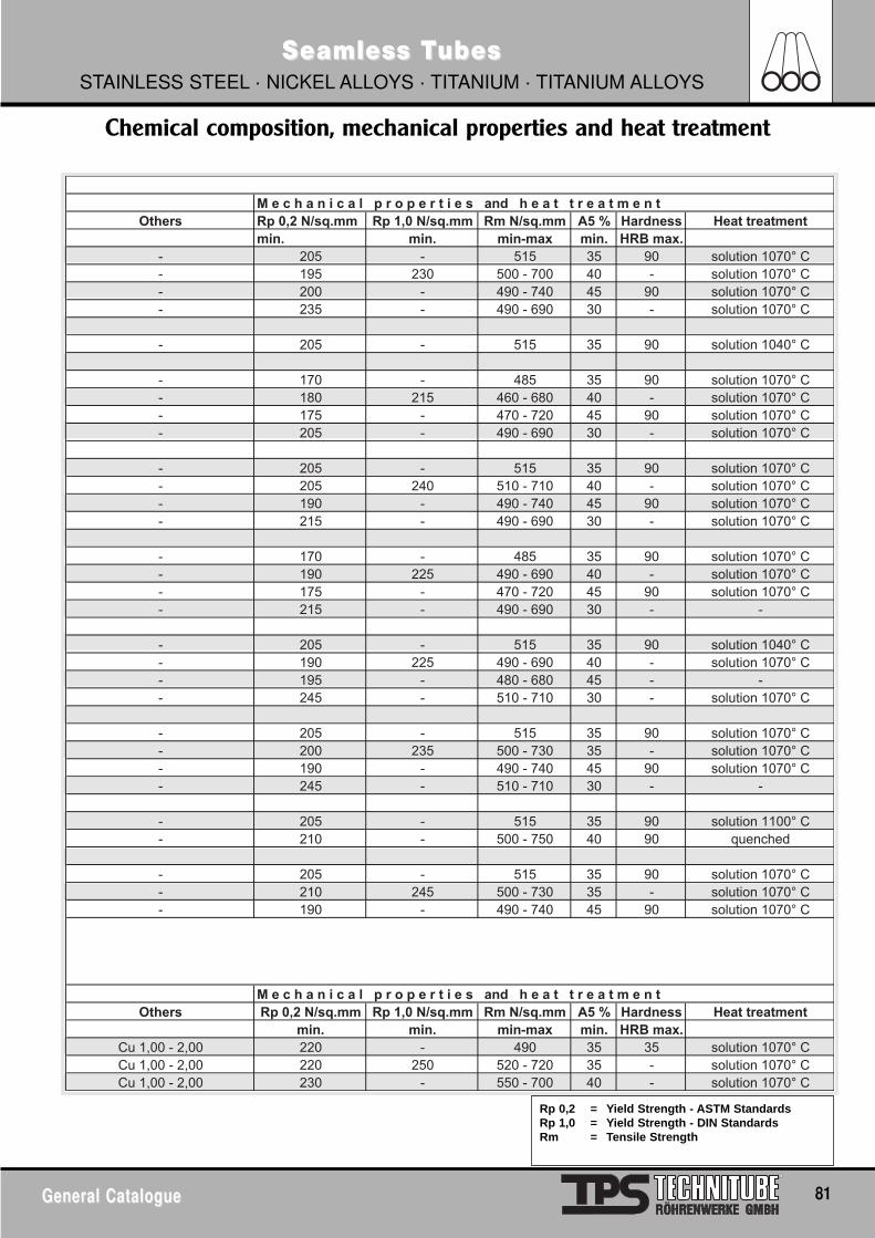
General CatalogueGeneral Catalogue 81
Seamless TSeamless TubesubesSTAINLESS STEEL · NICKEL ALLOYS · TITANIUM · TITANIUM ALLOYS
Chemical composition, mechanical properties and heat treatment
M e c h a n i c a l p r o p e r t i e s and h e a t t r e a t m e n tOthers Rp 0,2 N/sq.mm Rp 1,0 N/sq.mm Rm N/sq.mm A5 % Hardness Heat treatment
min. min. min-max min. HRB max.- 205 - 515 35 90 solution 1070° C- 195 230 500 - 700 40 - solution 1070° C- 200 - 490 - 740 45 90 solution 1070° C- 235 - 490 - 690 30 - solution 1070° C
- 205 - 515 35 90 solution 1040° C
- 170 - 485 35 90 solution 1070° C- 180 215 460 - 680 40 - solution 1070° C- 175 - 470 - 720 45 90 solution 1070° C- 205 - 490 - 690 30 - solution 1070° C
- 205 - 515 35 90 solution 1070° C- 205 240 510 - 710 40 - solution 1070° C- 190 - 490 - 740 45 90 solution 1070° C- 215 - 490 - 690 30 - solution 1070° C
- 170 - 485 35 90 solution 1070° C- 190 225 490 - 690 40 - solution 1070° C- 175 - 470 - 720 45 90 solution 1070° C- 215 - 490 - 690 30 - -
- 205 - 515 35 90 solution 1040° C- 190 225 490 - 690 40 - solution 1070° C- 195 - 480 - 680 45 - -- 245 - 510 - 710 30 - solution 1070° C
- 205 - 515 35 90 solution 1070° C- 200 235 500 - 730 35 - solution 1070° C- 190 - 490 - 740 45 90 solution 1070° C- 245 - 510 - 710 30 - -
- 205 - 515 35 90 solution 1100° C- 210 - 500 - 750 40 90 quenched
- 205 - 515 35 90 solution 1070° C- 210 245 500 - 730 35 - solution 1070° C- 190 - 490 - 740 45 90 solution 1070° C
M e c h a n i c a l p r o p e r t i e s and h e a t t r e a t m e n tOthers Rp 0,2 N/sq.mm Rp 1,0 N/sq.mm Rm N/sq.mm A5 % Hardness Heat treatment
min. min. min-max min. HRB max.Cu 1,00 - 2,00 220 - 490 35 35 solution 1070° CCu 1,00 - 2,00 220 250 520 - 720 35 - solution 1070° CCu 1,00 - 2,00 230 - 550 - 700 40 - solution 1070° C
Rp 0,2 = Yield Strength - ASTM StandardsRp 1,0 = Yield Strength - DIN StandardsRm = Tensile Strength
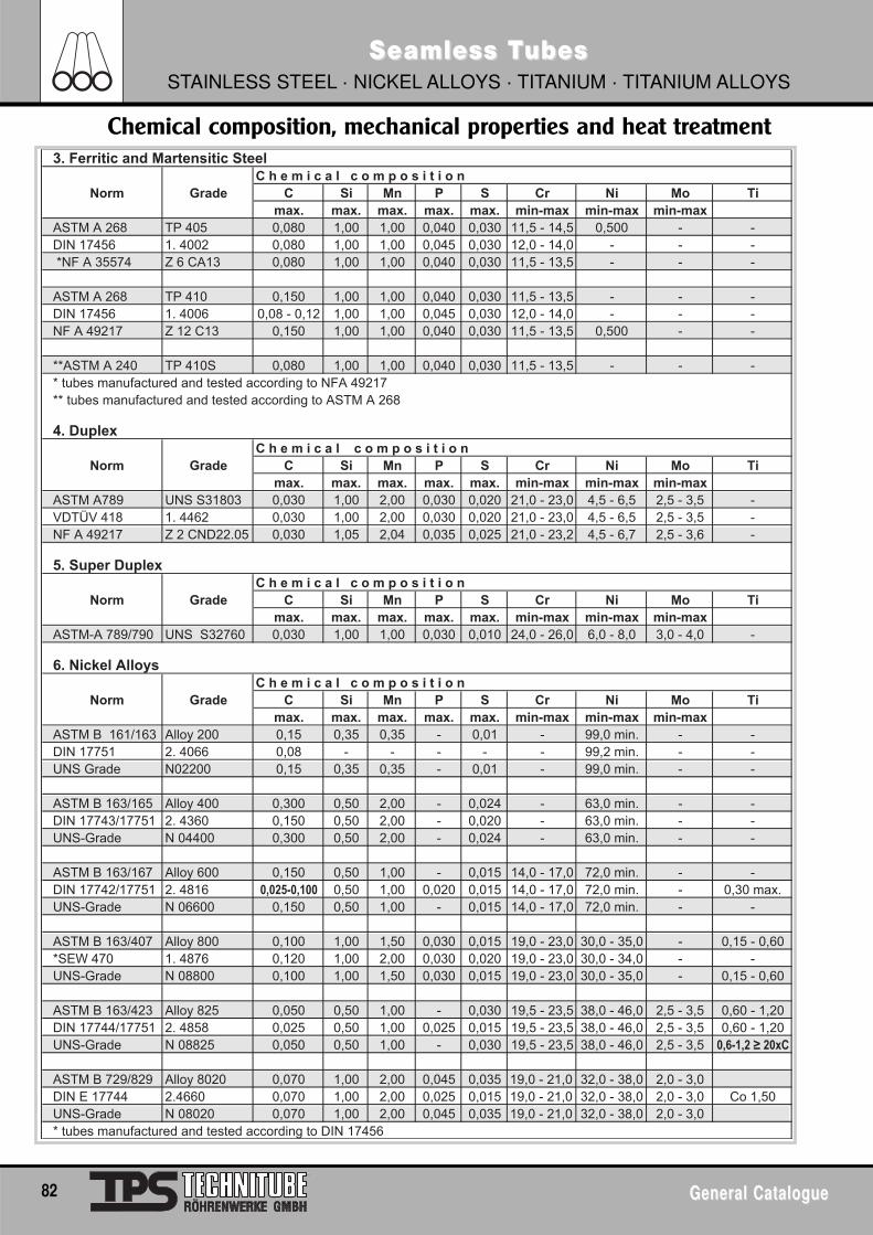
82 General CatalogueGeneral Catalogue
Seamless TSeamless TubesubesSTAINLESS STEEL · NICKEL ALLOYS · TITANIUM · TITANIUM ALLOYS
Chemical composition, mechanical properties and heat treatment3. Ferritic and Martensitic Steel
C h e m i c a l c o m p o s i t i o nNorm Grade C Si Mn P S Cr Ni Mo Ti
max. max. max. max. max. min-max min-max min-maxASTM A 268 TP 405 0,080 1,00 1,00 0,040 0,030 11,5 - 14,5 0,500 - -DIN 17456 1. 4002 0,080 1,00 1,00 0,045 0,030 12,0 - 14,0 - - - *NF A 35574 Z 6 CA13 0,080 1,00 1,00 0,040 0,030 11,5 - 13,5 - - -
ASTM A 268 TP 410 0,150 1,00 1,00 0,040 0,030 11,5 - 13,5 - - -DIN 17456 1. 4006 0,08 - 0,12 1,00 1,00 0,045 0,030 12,0 - 14,0 - - -NF A 49217 Z 12 C13 0,150 1,00 1,00 0,040 0,030 11,5 - 13,5 0,500 - -
**ASTM A 240 TP 410S 0,080 1,00 1,00 0,040 0,030 11,5 - 13,5 - - -* tubes manufactured and tested according to NFA 49217** tubes manufactured and tested according to ASTM A 268
4. DuplexC h e m i c a l c o m p o s i t i o n
Norm Grade C Si Mn P S Cr Ni Mo Timax. max. max. max. max. min-max min-max min-max
ASTM A789 UNS S31803 0,030 1,00 2,00 0,030 0,020 21,0 - 23,0 4,5 - 6,5 2,5 - 3,5 -VDTÜV 418 1. 4462 0,030 1,00 2,00 0,030 0,020 21,0 - 23,0 4,5 - 6,5 2,5 - 3,5 -NF A 49217 Z 2 CND22.05 0,030 1,05 2,04 0,035 0,025 21,0 - 23,2 4,5 - 6,7 2,5 - 3,6 -
5. Super DuplexC h e m i c a l c o m p o s i t i o n
Norm Grade C Si Mn P S Cr Ni Mo Timax. max. max. max. max. min-max min-max min-max
ASTM-A 789/790 UNS S32760 0,030 1,00 1,00 0,030 0,010 24,0 - 26,0 6,0 - 8,0 3,0 - 4,0 -
6. Nickel AlloysC h e m i c a l c o m p o s i t i o n
Norm Grade C Si Mn P S Cr Ni Mo Timax. max. max. max. max. min-max min-max min-max
ASTM B 161/163 Alloy 200 0,15 0,35 0,35 - 0,01 - 99,0 min. - -DIN 17751 2. 4066 0,08 - - - - - 99,2 min. - -UNS Grade N02200 0,15 0,35 0,35 - 0,01 - 99,0 min. - -
ASTM B 163/165 Alloy 400 0,300 0,50 2,00 - 0,024 - 63,0 min. - -DIN 17743/17751 2. 4360 0,150 0,50 2,00 - 0,020 - 63,0 min. - -UNS-Grade N 04400 0,300 0,50 2,00 - 0,024 - 63,0 min. - -
ASTM B 163/167 Alloy 600 0,150 0,50 1,00 - 0,015 14,0 - 17,0 72,0 min. - -DIN 17742/17751 2. 4816 ����������� 0,50 1,00 0,020 0,015 14,0 - 17,0 72,0 min. - 0,30 max.UNS-Grade N 06600 0,150 0,50 1,00 - 0,015 14,0 - 17,0 72,0 min. - -
ASTM B 163/407 Alloy 800 0,100 1,00 1,50 0,030 0,015 19,0 - 23,0 30,0 - 35,0 - 0,15 - 0,60*SEW 470 1. 4876 0,120 1,00 2,00 0,030 0,020 19,0 - 23,0 30,0 - 34,0 - -UNS-Grade N 08800 0,100 1,00 1,50 0,030 0,015 19,0 - 23,0 30,0 - 35,0 - 0,15 - 0,60
ASTM B 163/423 Alloy 825 0,050 0,50 1,00 - 0,030 19,5 - 23,5 38,0 - 46,0 2,5 - 3,5 0,60 - 1,20DIN 17744/17751 2. 4858 0,025 0,50 1,00 0,025 0,015 19,5 - 23,5 38,0 - 46,0 2,5 - 3,5 0,60 - 1,20UNS-Grade N 08825 0,050 0,50 1,00 - 0,030 19,5 - 23,5 38,0 - 46,0 2,5 - 3,5 ������� � ���
ASTM B 729/829 Alloy 8020 0,070 1,00 2,00 0,045 0,035 19,0 - 21,0 32,0 - 38,0 2,0 - 3,0DIN E 17744 2.4660 0,070 1,00 2,00 0,025 0,015 19,0 - 21,0 32,0 - 38,0 2,0 - 3,0 Co 1,50UNS-Grade N 08020 0,070 1,00 2,00 0,045 0,035 19,0 - 21,0 32,0 - 38,0 2,0 - 3,0* tubes manufactured and tested according to DIN 17456
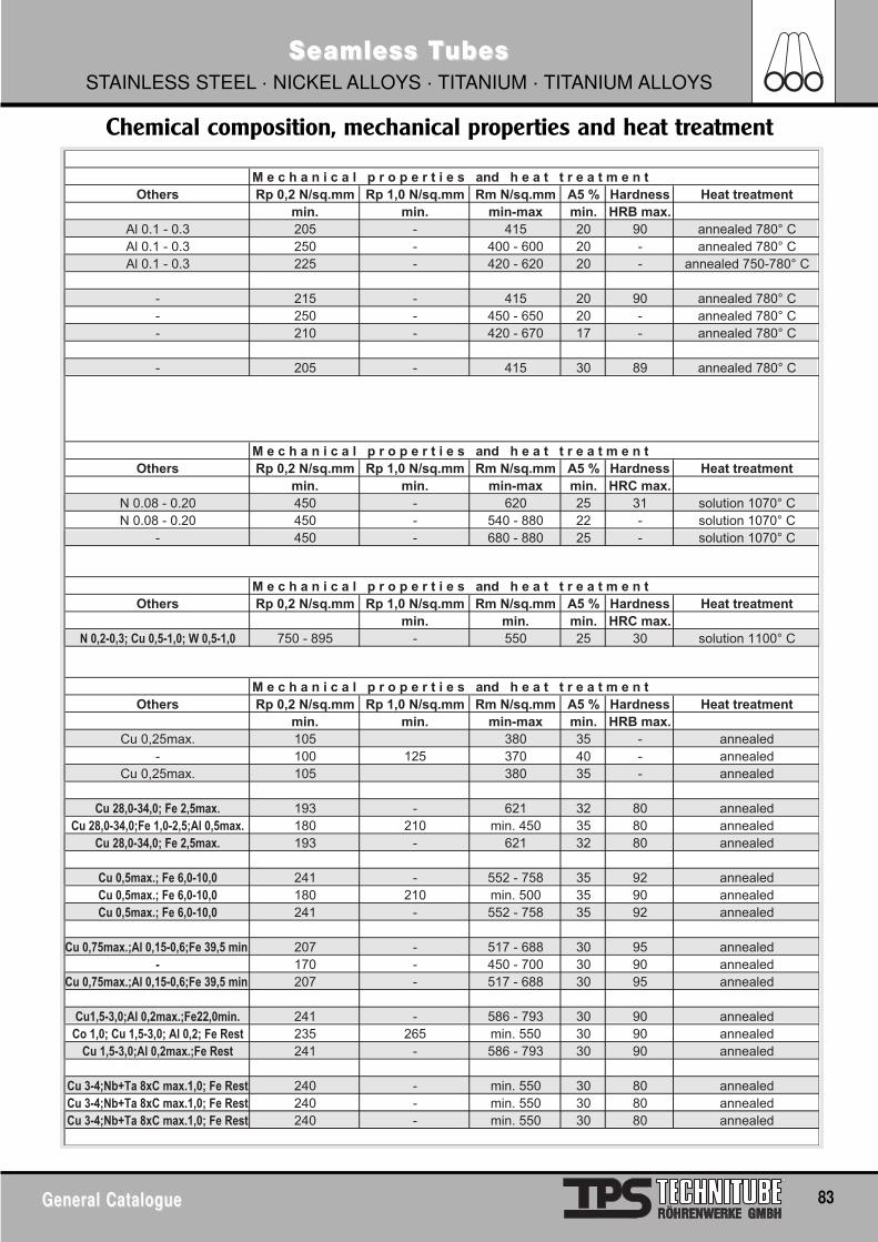
General CatalogueGeneral Catalogue 83
Seamless TSeamless TubesubesSTAINLESS STEEL · NICKEL ALLOYS · TITANIUM · TITANIUM ALLOYS
Chemical composition, mechanical properties and heat treatment
M e c h a n i c a l p r o p e r t i e s and h e a t t r e a t m e n tOthers Rp 0,2 N/sq.mm Rp 1,0 N/sq.mm Rm N/sq.mm A5 % Hardness Heat treatment
min. min. min-max min. HRB max.Al 0.1 - 0.3 205 - 415 20 90 annealed 780° CAl 0.1 - 0.3 250 - 400 - 600 20 - annealed 780° CAl 0.1 - 0.3 225 - 420 - 620 20 - annealed 750-780° C
- 215 - 415 20 90 annealed 780° C- 250 - 450 - 650 20 - annealed 780° C- 210 - 420 - 670 17 - annealed 780° C
- 205 - 415 30 89 annealed 780° C
M e c h a n i c a l p r o p e r t i e s and h e a t t r e a t m e n tOthers Rp 0,2 N/sq.mm Rp 1,0 N/sq.mm Rm N/sq.mm A5 % Hardness Heat treatment
min. min. min-max min. HRC max.N 0.08 - 0.20 450 - 620 25 31 solution 1070° CN 0.08 - 0.20 450 - 540 - 880 22 - solution 1070° C
- 450 - 680 - 880 25 - solution 1070° C
M e c h a n i c a l p r o p e r t i e s and h e a t t r e a t m e n tOthers Rp 0,2 N/sq.mm Rp 1,0 N/sq.mm Rm N/sq.mm A5 % Hardness Heat treatment
min. min. min. HRC max.� �������� �� ������ � ����� 750 - 895 - 550 25 30 solution 1100° C
M e c h a n i c a l p r o p e r t i e s and h e a t t r e a t m e n tOthers Rp 0,2 N/sq.mm Rp 1,0 N/sq.mm Rm N/sq.mm A5 % Hardness Heat treatment
min. min. min-max min. HRB max.Cu 0,25max. 105 380 35 - annealed
- 100 125 370 40 - annealedCu 0,25max. 105 380 35 - annealed
�� ������ ��� �� ������ 193 - 621 32 80 annealed�� ������ ����� �������� ������ 180 210 min. 450 35 80 annealed
�� ������ ��� �� ������ 193 - 621 32 80 annealed
�� ������� �� ������� 241 - 552 - 758 35 92 annealed�� ������� �� ������� 180 210 min. 500 35 90 annealed�� ������� �� ������� 241 - 552 - 758 35 92 annealed
�� ���������� ��������� ��� ���� 207 - 517 - 688 30 95 annealed� 170 - 450 - 700 30 90 annealed
�� ���������� ��������� ��� ���� 207 - 517 - 688 30 95 annealed
���������� ������������������ 241 - 586 - 793 30 90 annealed�� ��� �� ������ �� ���� �� ���� 235 265 min. 550 30 90 annealed�� �������� ���������� ���� 241 - 586 - 793 30 90 annealed
�� �� ��� !� ��� ������� �� ���� 240 - min. 550 30 80 annealed�� �� ��� !� ��� ������� �� ���� 240 - min. 550 30 80 annealed�� �� ��� !� ��� ������� �� ���� 240 - min. 550 30 80 annealed
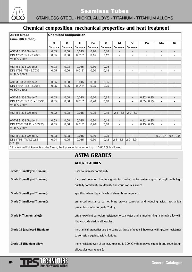
84 General CatalogueGeneral Catalogue
Seamless TSeamless TubesubesSTAINLESS STEEL · NICKEL ALLOYS · TITANIUM · TITANIUM ALLOYS
ASTM GRADESALLOY FEATURES
Grade 1 (unalloyed Titanium): used to increase formability.
Grade 2 (unalloyed Titanium): the most common Titanium grade for cooling water systems; good strength with high
ductility, formability, weldability and corrosion resistance.
Grade 3 (unalloyed Titanium): specified when higher levels of strength are required.
Grade 7 (unalloyed Titanium): enhanced resistance to hot brine crevice corrosion and reducing acids, mechanical
properties similar to grade 2 alloy.
Grade 9 (Titanium alloy): offers excellent corrosion resistance to sea water and is medium-high strength alloy with
highest code design allowables.
Grade 11 (unalloyed Titanium): mechanical properties are the same as those of grade 1 however, with greater resistance
to corrosion against acid chlorides.
Grade 12 (Titanium alloy): more resistant even at temperatures up to 300 C with improved strength and code design
allowables over grade 2.
ASTM Grade Chemical composition(sim. DIN Grade)
N C H Fe O Al V Pa Mo Ni
% max % max % max % max % max % max % max
ASTM B 338 Grade 1 0,03 0,08 0,015 0,20 0,18 - - - - -DIN 17861 Ti 1 - 3.7025 0,05 0,06 0,013* 0,15 0,12 - - - - -VdTÜV 230/2
ASTM B 338 Grade 2 0,03 0,08 0,015 0,30 0,25 - - - - -DIN 17861 Ti2 - 3.7035 0,05 0,06 0,013* 0,20 0,18 - - - - -VdTÜV 230/2
ASTM B 338 Grade 3 0,05 0,08 0,015 0,30 0,35 - - - - -DIN 17861 Ti 3 - 3.7055 0,05 0,06 0,013* 0,25 0,25 - - - - -VdTÜV 230/2
ASTM B 338 Grade 7 0,03 0,08 0,015 0,30 0,25 - - 0,12 - 0,25 - -DIN 17861 Ti 2 Pd - 3.7235 0,05 0,06 0,013* 0,20 0,18 - - 0,05 - 0,25 - -VdTÜV 230/2
ASTM B 338 Grade 9 0,02 0,08 0,015 0,25 0,15 2,5 - 3,5 2,0 - 3,0 - - -
ASTM B 338 Grade 11 0,03 0,08 0,015 0,20 0,18 - - 0,12 - 0,25 - -DIN 17861 Ti1 Pd - 3.7225 0,05 0,06 0,013* 0,20 0,18 - - 0,15 - 0,25 - -VdTÜV 230/2
ASTM B 338 Grade 12 0,03 0,08 0,015 0,30 0,25 - - - 0,2 - 0,4 0,6 - 0,9DIN 17861 Ti AL3V2,5 - 0,04 0,05 0,015 0,30 0,12 2,5 - 3,5 2,0 - 3,0 - - -3.7195* In case wallthickness is under 2 mm, the Hydrogenium-content up to 0,015 % is allowed.
Chemical composition, mechanical properties and heat treatment
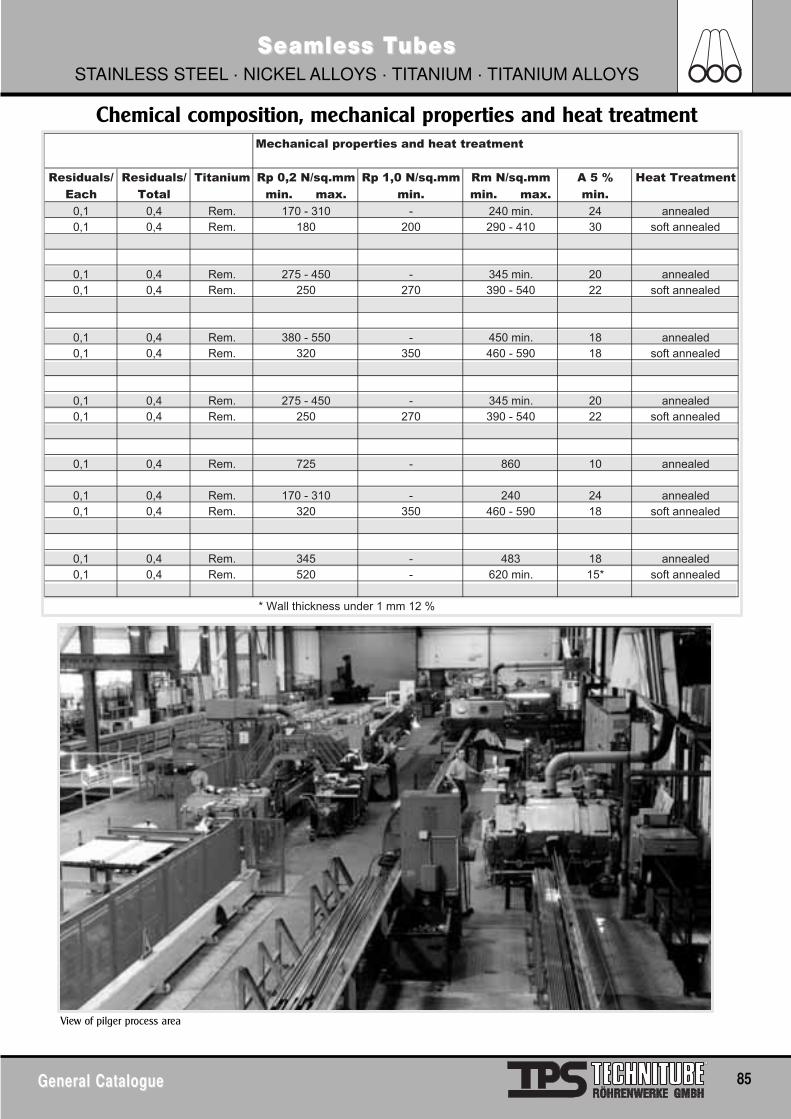
General CatalogueGeneral Catalogue 85
Seamless TSeamless TubesubesSTAINLESS STEEL · NICKEL ALLOYS · TITANIUM · TITANIUM ALLOYS
Mechanical properties and heat treatment
Residuals/ Residuals/ Titanium Rp 0,2 N/sq.mm Rp 1,0 N/sq.mm Rm N/sq.mm A 5 % Heat Treatment
Each Total min. max. min. min. max. min.
0,1 0,4 Rem. 170 - 310 - 240 min. 24 annealed0,1 0,4 Rem. 180 200 290 - 410 30 soft annealed
0,1 0,4 Rem. 275 - 450 - 345 min. 20 annealed0,1 0,4 Rem. 250 270 390 - 540 22 soft annealed
0,1 0,4 Rem. 380 - 550 - 450 min. 18 annealed0,1 0,4 Rem. 320 350 460 - 590 18 soft annealed
0,1 0,4 Rem. 275 - 450 - 345 min. 20 annealed0,1 0,4 Rem. 250 270 390 - 540 22 soft annealed
0,1 0,4 Rem. 725 - 860 10 annealed
0,1 0,4 Rem. 170 - 310 - 240 24 annealed0,1 0,4 Rem. 320 350 460 - 590 18 soft annealed
0,1 0,4 Rem. 345 - 483 18 annealed0,1 0,4 Rem. 520 - 620 min. 15* soft annealed
* Wall thickness under 1 mm 12 %
View of pilger process area
Chemical composition, mechanical properties and heat treatment
86 General CatalogueGeneral Catalogue
Seamless TSeamless TubesubesSTAINLESS STEEL · NICKEL ALLOYS · TITANIUM · TITANIUM ALLOYS
Technitube Röhrenwerke seamless tube production milland TechniPark
Pipes and Heat Exchanger TubesSeamless cold-finished tubes in the size range 6,0 up to 60,3 mm OD particularly in heatexchanger and condenser tube dimensions canbe supplied in fix- and random lengths, in straight lengths as well as in U-bend execution. seamless tubes in stainless steel, nickelalloys and titanium as mentioned are applied in Chemical-, Petrochemical-, Fertilizer-, Power-, Thermal Processing Plants and ShipbuildingIndustry all over the world. Even when applied under most severe operating conditions Seamless Tubes have proved that they meethighest requirements in respect to quality, performance and resistance.
GeneralWhereas the ASTM A 213 combined with tolerances according to ASTM A 450 exclusively prescribes minimum wall tolerance, the NFA andBS allows both, minimum wall and average wall tolerances.
An exception here presents the DIN standard. There are no indications about tolerances within the production standards of DIN17456/17458. Those are separately specified within the EN-ISO 1127 (previously: DIN 2462) and DIN 28180 giving several possibilities ofaverage wallthickness, whereby different combinations for O.D. and tolerance of wallthickness can be chosen.
Cold Finished Pipes
Manufacturing Standard DIN 17456 ASTM A 268 ASTM A 269 ASTM A 312 NFA 49117
Tol. Standard: EN-ISO 1127 ASTM A 268 ASTM A 269 ASTM A 530 Average wall
(prior: DIN 2462)
Tubes according to these specifications must not be used as heat exchanger tubes.
Cold Finished Heat Exchanger Tubes
Manufacturing Standard DIN 17458/AD-W2 ASTM A 213 NFA 49217
VD-TÜV-WB
Tol. Standard: EN-ISO 1127 ASTM A 450 Average wall
(previously:DIN 2462) (min. wall)
DIN 28180 Minimum wall
Tubes according to these specifications can be used as line pipes as well.
COMPARISON OF TOLERANCES
General CatalogueGeneral Catalogue 87
Cold Finished Pipes and Tubes
Seamless TSeamless TubesubesSTAINLESS STEEL · NICKEL ALLOYS · TITANIUM · TITANIUM ALLOYS
Specification Outside Diameter WallthicknessASTMA 450 < 25,4mm < 38,1mm < 50,8mm > 50,8 mm
+/- 0,10mm +/- 0,15mm +/- 0,20mm +/-0,25mm -0/+20% (min. wall)(average wall +/-10% not included)
A 530 < 48,3mm > 48,3mm +0,4/-0,8mm +/-0,8mm +/-12,5%
A 269 < 38,1mm < 63,5mm +/- 0,13mm +/-0,25mm +/-10%
EN-ISO 1127 (previously: DIN 2462)Tol.class TC D2 +/-1,00% min.+/-0,5mm T 2 +/-12,5% min. +/-0,40 mm
TC D3 +/-0,75% min. +/-0,3mm T 3 +/-10% min. +/-0,20 mm
TC D4 +/-0,50% min. +/-0,1mm T 4 +/-7,5% min. +/-0,15 mm
DIN 28180 (valid only for heatexchanger dimensions)Tol.class 16-20mm 25mm 30mm 38mm < 2 mm > 2 mm
TC 1 +/-0,10mm 0,12mm 0,15mm 0,20mm +/-0,2mm +/-10%TC 2 0,30mm 0,30mm 0,30mm 0,40mm +/-0,2mm +/-10%TC 3 - - - - +/-0,2mm +15/-10%
NFA Quality F (cold finished)49117 Quality F (cold finished) +/-0,75% with a minimum tolerances of +/-0,30mm +/-10% with a minimum of +/-0,20 mm
49217 < 25,4mm < 38,1mm < 50,8mm >50,8mmFerritic +/-0,10mm +/-0,15mm +/-0,20mm +/-0,50% normally +/-10%Austenitic+Austenitic-Ferritic +/-0,25mm +/-0,25mm +/-0,25mm +/-0,50% (on request:-0+20% min. wall)
BS CFS3059 Part 2 Austenitic +/-0,50% with a minimum tolerances of +/-0,15mm +/-10%(<3,25 mm) +/-7,5%(>3,25 mm)
3605 Part 1 Austenitic +/-0,75% with a minimum tolerances of +/-0,20mm +/- 10% min. +/- 0,15 mm
3606 < 25mm < 38mm < 50mmFerritic +/-0,10mm +/-0,15mm +/-0,20mm +/-10%Austenitic +/-0,15mm +/-0,15mm +/-0,20mm (on request:-0/+20% or -0/+22%)
COMPARISON OF TOLERANCES
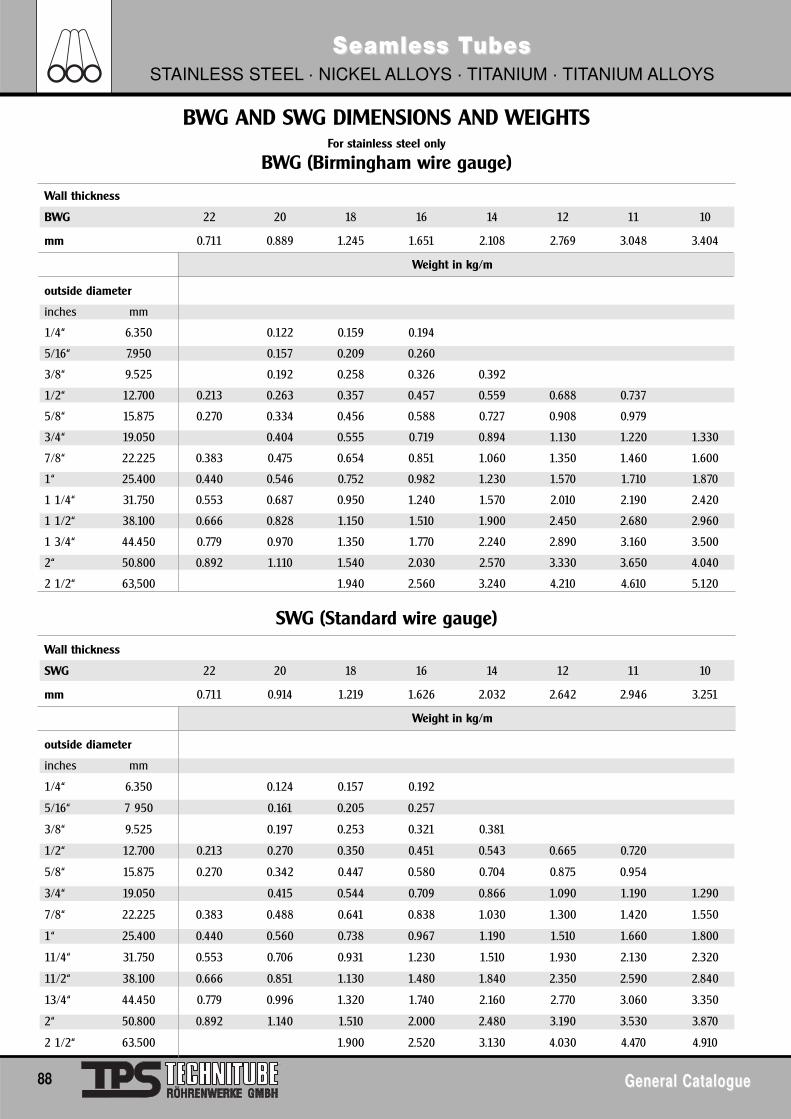
88 General CatalogueGeneral Catalogue
Seamless TSeamless TubesubesSTAINLESS STEEL · NICKEL ALLOYS · TITANIUM · TITANIUM ALLOYS
BWG AND SWG DIMENSIONS AND WEIGHTSFor stainless steel only
BWG (Birmingham wire gauge)
Wall thickness
BWG 22 20 18 16 14 12 11 10
mm 0.711 0.889 1.245 1.651 2.108 2.769 3.048 3.404
Weight in kg/m
outside diameter
inches mm
1/4“ 6.350 0.122 0.159 0.194
5/16“ 7.950 0.157 0.209 0.260
3/8“ 9.525 0.192 0.258 0.326 0.392
1/2“ 12.700 0.213 0.263 0.357 0.457 0.559 0.688 0.737
5/8“ 15.875 0.270 0.334 0.456 0.588 0.727 0.908 0.979
3/4“ 19.050 0.404 0.555 0.719 0.894 1.130 1.220 1.330
7/8“ 22.225 0.383 0.475 0.654 0.851 1.060 1.350 1.460 1.600
1“ 25.400 0.440 0.546 0.752 0.982 1.230 1.570 1.710 1.870
1 1/4“ 31.750 0.553 0.687 0.950 1.240 1.570 2.010 2.190 2.420
1 1/2“ 38.100 0.666 0.828 1.150 1.510 1.900 2.450 2.680 2.960
1 3/4“ 44.450 0.779 0.970 1.350 1.770 2.240 2.890 3.160 3.500
2“ 50.800 0.892 1.110 1.540 2.030 2.570 3.330 3.650 4.040
2 1/2“ 63,500 1.940 2.560 3.240 4.210 4.610 5.120
SWG (Standard wire gauge)
Wall thickness
SWG 22 20 18 16 14 12 11 10
mm 0.711 0.914 1.219 1.626 2.032 2.642 2.946 3.251
Weight in kg/m
outside diameter
inches mm
1/4“ 6.350 0.124 0.157 0.192
5/16“ 7 950 0.161 0.205 0.257
3/8“ 9.525 0.197 0.253 0.321 0.381
1/2“ 12.700 0.213 0.270 0.350 0.451 0.543 0.665 0.720
5/8“ 15.875 0.270 0.342 0.447 0.580 0.704 0.875 0.954
3/4“ 19.050 0.415 0.544 0.709 0.866 1.090 1.190 1.290
7/8“ 22.225 0.383 0.488 0.641 0.838 1.030 1.300 1.420 1.550
1“ 25.400 0.440 0.560 0.738 0.967 1.190 1.510 1.660 1.800
11/4“ 31.750 0.553 0.706 0.931 1.230 1.510 1.930 2.130 2.320
11/2“ 38.100 0.666 0.851 1.130 1.480 1.840 2.350 2.590 2.840
13/4“ 44.450 0.779 0.996 1.320 1.740 2.160 2.770 3.060 3.350
2“ 50.800 0.892 1.140 1.510 2.000 2.480 3.190 3.530 3.870
2 1/2“ 63.500 1.900 2.520 3.130 4.030 4.470 4.910
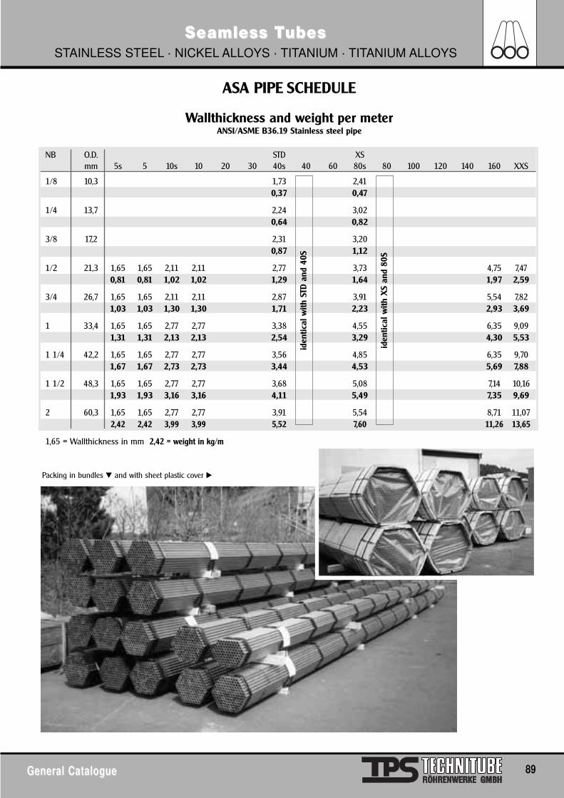
General CatalogueGeneral Catalogue 89
Seamless TSeamless TubesubesSTAINLESS STEEL · NICKEL ALLOYS · TITANIUM · TITANIUM ALLOYS
Wallthickness and weight per meterANSI/ASME B36.19 Stainless steel pipe
NB O.D. STD XSmm 5s 5 10s 10 20 30 40s 40 60 80s 80 100 120 140 160 XXS
1/8 10,3 1,73 2,410,37 0,47
1/4 13,7 2,24 3,020,64 0,82
3/8 17,2 2,31 3,200,87 1,12
1/2 21,3 1,65 1,65 2,11 2,11 2,77 3,73 4,75 7,470,81 0,81 1,02 1,02 1,29 1,64 1,97 2,59
3/4 26,7 1,65 1,65 2,11 2,11 2,87 3,91 5,54 7,821,03 1,03 1,30 1,30 1,71 2,23 2,93 3,69
1 33,4 1,65 1,65 2,77 2,77 3,38 4,55 6,35 9,091,31 1,31 2,13 2,13 2,54 3,29 4,30 5,53
1 1/4 42,2 1,65 1,65 2,77 2,77 3,56 4,85 6,35 9,701,67 1,67 2,73 2,73 3,44 4,53 5,69 7,88
1 1/2 48,3 1,65 1,65 2,77 2,77 3,68 5,08 7,14 10,161,93 1,93 3,16 3,16 4,11 5,49 7,35 9,69
2 60,3 1,65 1,65 2,77 2,77 3,91 5,54 8,71 11,072,42 2,42 3,99 3,99 5,52 7,60 11,26 13,65
1,65 = Wallthickness in mm 2,42 = weight in kg/m
ASA PIPE SCHEDULE
Packing in bundles � and with sheet plastic cover �
iden
tical
with
STD
and
40S
iden
tical
with
XS
and
80S
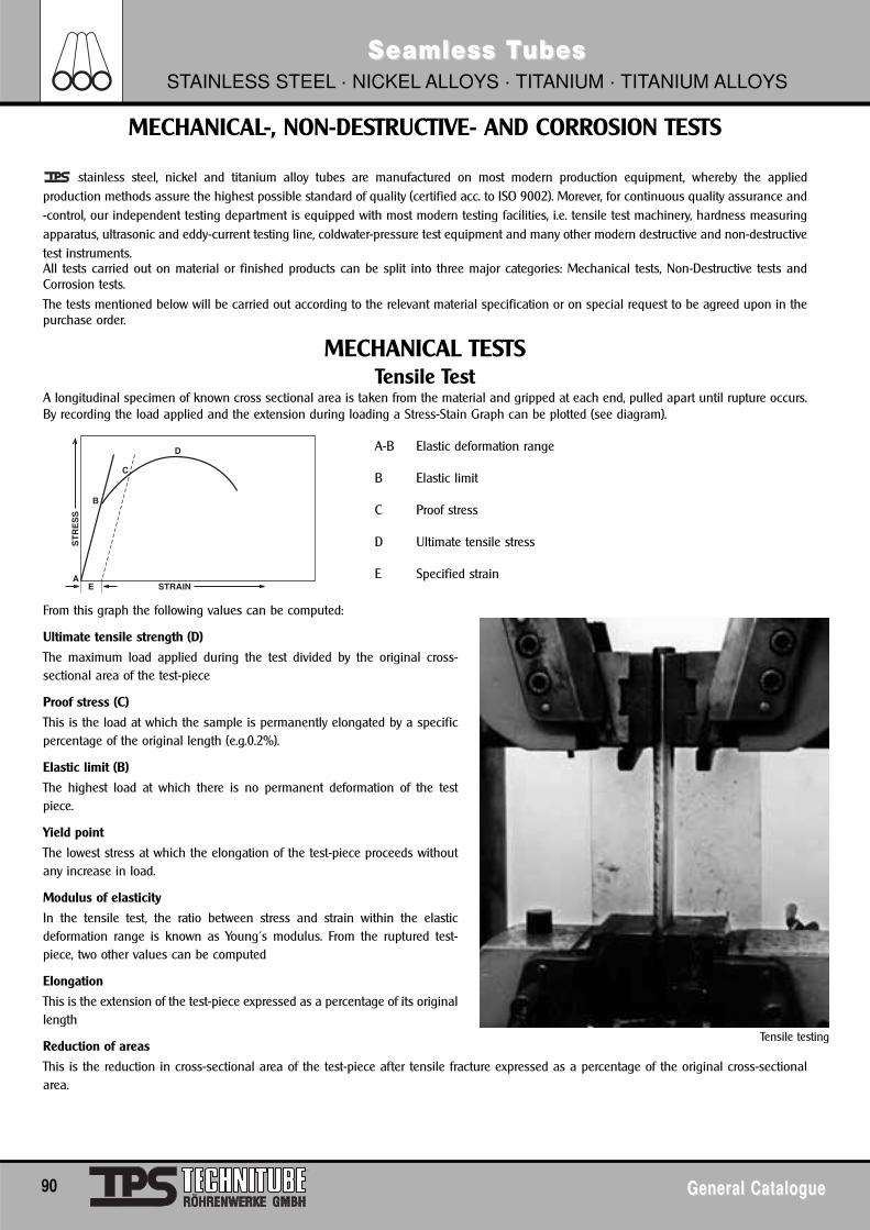
90 General CatalogueGeneral Catalogue
Seamless TSeamless TubesubesSTAINLESS STEEL · NICKEL ALLOYS · TITANIUM · TITANIUM ALLOYS
stainless steel, nickel and titanium alloy tubes are manufactured on most modern production equipment, whereby the appliedproduction methods assure the highest possible standard of quality (certified acc. to ISO 9002). Morever, for continuous quality assurance and-control, our independent testing department is equipped with most modern testing facilities, i.e. tensile test machinery, hardness measuringapparatus, ultrasonic and eddy-current testing line, coldwater-pressure test equipment and many other modern destructive and non-destructivetest instruments.All tests carried out on material or finished products can be split into three major categories: Mechanical tests, Non-Destructive tests andCorrosion tests.
The tests mentioned below will be carried out according to the relevant material specification or on special request to be agreed upon in thepurchase order.
MECHANICAL TESTSTensile Test
A longitudinal specimen of known cross sectional area is taken from the material and gripped at each end, pulled apart until rupture occurs.By recording the load applied and the extension during loading a Stress-Stain Graph can be plotted (see diagram).
A-B Elastic deformation range
B Elastic limit
C Proof stress
D Ultimate tensile stress
E Specified strain
From this graph the following values can be computed:
Ultimate tensile strength (D)
The maximum load applied during the test divided by the original cross-sectional area of the test-piece
Proof stress (C)
This is the load at which the sample is permanently elongated by a specificpercentage of the original length (e.g.0.2%).
Elastic limit (B)
The highest load at which there is no permanent deformation of the testpiece.
Yield point
The lowest stress at which the elongation of the test-piece proceeds withoutany increase in load.
Modulus of elasticity
In the tensile test, the ratio between stress and strain within the elasticdeformation range is known as Young´s modulus. From the ruptured test-piece, two other values can be computed
Elongation
This is the extension of the test-piece expressed as a percentage of its originallength
Reduction of areas
This is the reduction in cross-sectional area of the test-piece after tensile fracture expressed as a percentage of the original cross-sectionalarea.
MECHANICAL-, NON-DESTRUCTIVE- AND CORROSION TESTS
Tensile testing
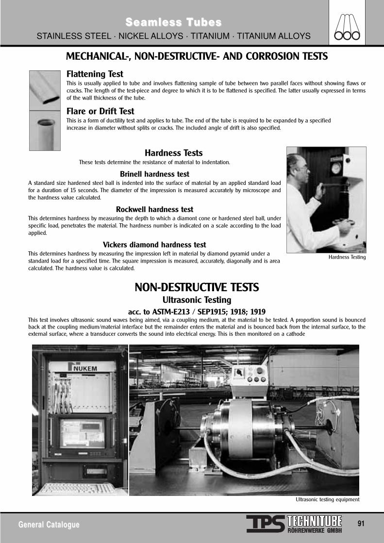
General CatalogueGeneral Catalogue 91
Seamless TSeamless TubesubesSTAINLESS STEEL · NICKEL ALLOYS · TITANIUM · TITANIUM ALLOYS
MECHANICAL-, NON-DESTRUCTIVE- AND CORROSION TESTS
Flattening TestThis is usually applied to tube and involves flattening sample of tube between two parallel faces without showing flaws orcracks. The length of the test-piece and degree to which it is to be flattened is specified. The latter usually expressed in termsof the wall thickness of the tube.
Flare or Drift TestThis is a form of ductility test and applies to tube. The end of the tube is required to be expanded by a specifiedincrease in diameter without splits or cracks. The included angle of drift is also specified.
Hardness TestsThese tests determine the resistance of material to indentation.
Brinell hardness testA standard size hardened steel ball is indented into the surface of material by an applied standard loadfor a duration of 15 seconds. The diameter of the impression is measured accurately by microscope andthe hardness value calculated.
Rockwell hardness testThis determines hardness by measuring the depth to which a diamont cone or hardened steel ball, underspecific load, penetrates the material. The hardness number is indicated on a scale according to the loadapplied.
Vickers diamond hardness testThis determines hardness by measuring the impression left in material by diamond pyramid under astandard load for a specified time. The square impression is measured, accurately, diagonally and is areacalculated. The hardness value is calculated.
NON-DESTRUCTIVE TESTSUltrasonic Testing
acc. to ASTM-E213 / SEP1915; 1918; 1919This test involves ultrasonic sound waves being aimed, via a coupling medium, at the material to be tested. A proportion sound is bouncedback at the coupling medium/material interface but the remainder enters the material and is bounced back from the internal surface, to theexternal surface, where a transducer converts the sound into electrical energy. This is then monitored on a cathode
Hardness Testing
Ultrasonic testing equipment
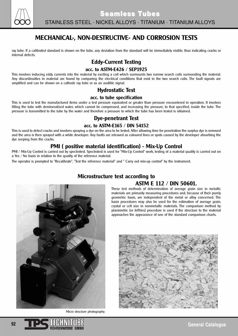
92 General CatalogueGeneral Catalogue
Seamless TSeamless TubesubesSTAINLESS STEEL · NICKEL ALLOYS · TITANIUM · TITANIUM ALLOYS
Micro structure photography
MECHANICAL-, NON-DESTRUCTIVE- AND CORROSION TESTS
ray tube. If a calibrated standard is shown on the tube, any deviation from the standard will be immediately visible, thus indicating cracks orinternal defects.
Eddy-Current Testingacc. to ASTM-E426 / SEP1925
This involves inducing eddy currents into the material by exciting a coil which surmounts two narrow search coils surrounding the material.Any discontinuities in material are found by comparing the electrical conditions that exist in the two search coils. The fault signals areamplified and can be shown on a cathode ray tube or as an audible signal.
Hydrostatic Testacc. to tube specification
This is used to test the manufactured items under a test pressure equivalent or greater than pressure encountered in operation. It involvesfilling the tube with demineralized water, which cannot be compressed, and increasing the pressure, to that specified, inside the tube. Thepressure is transmitted to the tube by the water and therefore a pressure to which the tube has been tested is obtained.
Dye-penetrant Testacc. to ASTM-E165 / DIN 54152
This is used to detect cracks and involves spraying a dye on the area to be tested. After allowing time for penetration the surplus dye is removedand the area is then sprayed with a white developer. Any faults are releaved as coloured lines or spots caused by the developer absorbing thedye seeping from the cracks.
PMI ( positive material identification) - Mix-Up Control PMI / Mix-Up Control is carried out by spectrotest. Spectrotest is used for "Mix-Up Control" work, testing of a material quality is carried out ona Yes / No basis in relation to the quality of the reference material.
The operator is prompted to "Recalibrate", "Test the reference material" and " Carry out mix-up control" by the instrument.
Microstructure test according to ASTM E 112 / DIN 50601.
These test methods of determination of average grain size in metallicmaterials are primarily measuring procedures and, because of their purelygeometric basis, are independent of the metal or alloy concerned. Thebasis procedures may also be used for the estimation of average grain,crystal or cell size in nonmetallic materials. The comparison method byplanimetric (or Jeffries) procedure is used if the structure to the materialapproaches the appearance of one of the standard comparison charts.
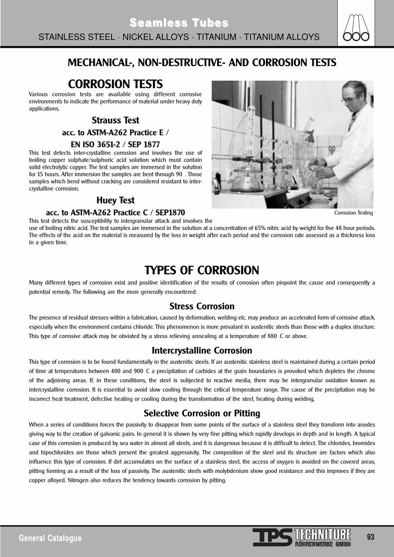
General CatalogueGeneral Catalogue 93
Seamless TSeamless TubesubesSTAINLESS STEEL · NICKEL ALLOYS · TITANIUM · TITANIUM ALLOYS
MECHANICAL-, NON-DESTRUCTIVE- AND CORROSION TESTS
CORROSION TESTSVarious corrosion tests are available using different corrosiveenvironments to indicate the performance of material under heavy dutyapplications.
Strauss Testacc. to ASTM-A262 Practice E /
EN ISO 3651-2 / SEP 1877This test detects inter-crystalline corrosion and involves the use ofboiling copper sulphate/sulphuric acid solution which must containsolid electrolytic copper. The test samples are immersed in the solutionfor 15 hours. After immersion the samples are bent through 90 . Thosesamples which bend without cracking are considered resistant to inter-crystalline corrosion.
Huey Testacc. to ASTM-A262 Practice C / SEP1870
This test detects the susceptibility to intergranular attack and involves theuse of boiling nitric acid. The test samples are immersed in the solution at a concentration of 65% nitric acid by weight for five 48 hour periods.The effects of the acid on the material is measured by the loss in weight after each period and the corrosion rate assessed as a thickness lossin a given time.
TYPES OF CORROSIONMany different types of corrosion exist and positive identification of the results of corrosion often pinpoint the cause and consequently a
potential remedy. The following are the more generally encountered:
Stress CorrosionThe presence of residual stresses within a fabrication, caused by deformation, welding etc. may produce an accelerated form of corrosive attack,
especially when the environment contains chloride. This phenomenon is more prevalant in austenitic steels than those with a duplex structure.
This type of corrosive attack may be obviated by a stress relieving annealing at a temperature of 880 C or above.
Intercrystalline CorrosionThis type of corrosion is to be found fundamentally in the austenitic steels. If an austenitic stainless steel is maintained during a certain period
of time at temperatures between 400 and 900 C a precipitation of carbides at the grain boundaries is provoked which depletes the chrome
of the adjoining areas. If, in these conditions, the steel is subjected to reactive media, there may be intergranular oxidation known as
intercrystalline corrosion. It is essential to avoid slow cooling through the critical temperature range. The cause of the precipitation may be
incorrect heat treatment, defective heating or cooling during the transformation of the steel, heating during welding.
Selective Corrosion or PittingWhen a series of conditions forces the passivity to disappear from some points of the surface of a stainless steel they transform into anodes
giving way to the creation of galvanic pairs. In general it is shown by very fine pitting which rapidly develops in depth and in length. A typical
case of this corrosion is produced by sea water in almost all steels, and it is dangerous because it is difficult to detect. The chlorides, bromides
and hipochlorides are those which present the greatest aggressivity. The composition of the steel and its structure are factors which also
influence this type of corrosion. If dirt accumulates on the surface of a stainless steel, the access of oxygen is avoided on the covered areas,
pitting forming as a result of the loss of passivity. The austenitic steels with molybdenium show good resistance and this improves if they are
copper alloyed. Nitrogen also reduces the tendency towards corrosion by pitting.
Corrosion Testing
94 General CatalogueGeneral Catalogue
Seamless TSeamless TubesubesSTAINLESS STEEL · NICKEL ALLOYS · TITANIUM · TITANIUM ALLOYS
Types of Inspection Documents DIN EN 10204(previously DIN 50.049)
1 GeneralThis European Standard defines the different types of inspection documents supplied to the purchaser, in accordance with the requirementsof the order, for the delivery of metallic products.
2 Inspection documents drawn up from inspection and tests carried out by personnel authorized by the manufacturer and who maybe involved in the manufacturing department
Certificate of compliance with the order 2.1/EN 10204 Document in which the manufacturer certifies that the products supplied are in compliance with the requirements of the order, withoutmention of any test results.
The certificate of compliance with the order is a document drawn up on the basis of non-specific inspection and testing.
Test report 2.2/EN 10204 Document in which the manufacturer certifies that the products supplied are in compliance with the requirements of the order and inwhich he supplies test results based on non-specific inspection and testing.
Specific test report 2.3/EN 10204 Document in which the manufacturer certifies that the products supplied are in compliance with the specifications of the order and inwhich he supplies test results based on specific inspection and testing.
(The specific test report is only used by a manufacturer who does not have an authorized quality control department operatingindependently of the manufacturing department).
3 Inspection documents drawn up from inspection and tests carried out or supervised by authorized personnel independent of themanufacturing department, and based on specific testing
Inspection certificate 3.1.Document issued on the basis of inspection and tests carried out in accordance with the technical specifications of the order or theofficial regulations and the corresponding technical rules. The tests shall be carried out on the products supplied or the products in theinspection unit, of which the consignment constitutes a part.
The inspection unit is set by the product standard, the official regulations and corresponding technical rules or by the order.
There are different types:
Inspection certificate 3.1.B/EN 10204is issued by the department independent of the manufacturing department and validated by an authorized representative of thestaff independent of the manufacturing department.
Inspection certificate 3.1.C/EN 10204is issued and validated by an authorized representative of the purchaser, in accordance with the specifications of the order.
Inspection report 3.2/EN 10204 Where the inspection certificate is validated, following special agreement, both by the manufacturer´s authorized representative and thepurchaser´s authorized representative, it is known as the inspection report.
INSPECTION DOCUMENTS
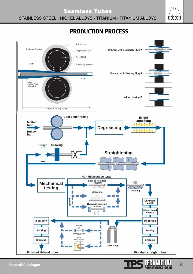
General CatalogueGeneral Catalogue 95
Seamless TSeamless TubesubesSTAINLESS STEEL · NICKEL ALLOYS · TITANIUM · TITANIUM ALLOYS
PRODUCTION PROCESS
Stroke of Rolling Stand
Mandrel
LuppeMother TubeHollow bar
Reducing Section
Roll Groove
Ring-shaped Die
Axis of Roll
Smoothing Section
Tube
Cold pilger rolling
Degreasing
Mechanicaltesting
Straightening
US-testing
Eddy current test
Marking
Finished straight tubes
U-bending
Finished U-bend tubes
Non-destructive tests
Drawing
Hydraulic pressuretesting
Mothertube
Cutting tolength
Inspection
Packing
Shipping
Dimensionalchecks
Inspection
Packing
Shipping
Optionally
Hydraulic pressuretesting
and / or
Stress-relievingannealing
Swage
Hollowbar
Drawing with Stationary Plug �
Drawing with Floating Plug �
Hollow Drawing �
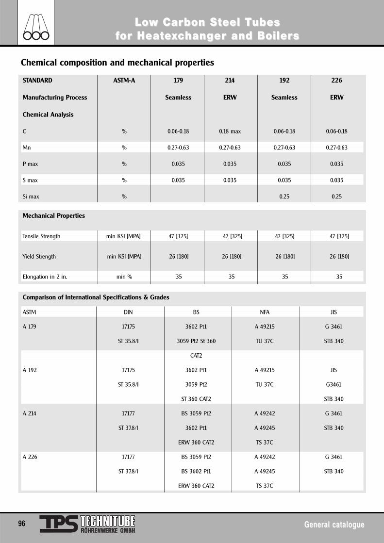
LoLow Carbon Sw Carbon Stteel Teel Tubesubesffor Heator Heateexxcchanghanger and Boilerer and Boilerss
96 General catalogueGeneral catalogue
STANDARD ASTM-A 179 214 192 226
Manufacturing Process Seamless ERW Seamless ERW
Chemical Analysis
C % 0.06-0.18 0.18 max 0.06-0.18 0.06-0.18
Mn % 0.27-0.63 0.27-0.63 0.27-0.63 0.27-0.63
P max % 0.035 0.035 0.035 0.035
S max % 0.035 0.035 0.035 0.035
Si max % 0.25 0.25
Chemical composition and mechanical properties
Mechanical Properties
Tensile Strength min KSI [MPA] 47 [325] 47 [325] 47 [325] 47 [325]
Yield Strength min KSI [MPA] 26 [180] 26 [180] 26 [180] 26 [180]
Elongation in 2 in. min % 35 35 35 35
Comparison of International Specifications & Grades
ASTM DIN BS NFA JIS
A 179 17175 3602 Pt1 A 49215 G 3461
ST 35.8/I 3059 Pt2 St 360 TU 37C STB 340
CAT2
A 192 17175 3602 Pt1 A 49215 JIS
ST 35.8/I 3059 Pt2 TU 37C G3461
ST 360 CAT2 STB 340
A 214 17177 BS 3059 Pt2 A 49242 G 3461
ST 37.8/I 3602 Pt1 A 49245 STB 340
ERW 360 CAT2 TS 37C
A 226 17177 BS 3059 Pt2 A 49242 G 3461
ST 37.8/I BS 3602 Pt1 A 49245 STB 340
ERW 360 CAT2 TS 37C
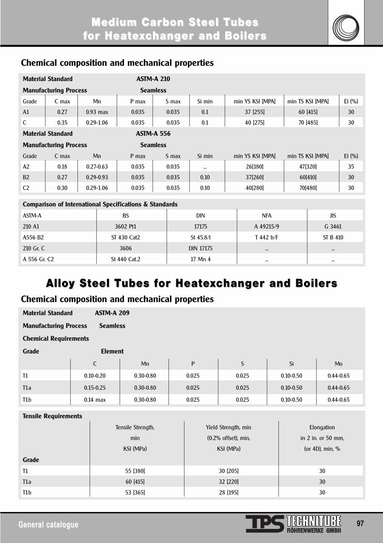
Medium Carbon SMedium Carbon Stteel Teel Tubesubesffor Heator Heateexxcchanghanger and Boilerer and Boilerss
General catalogueGeneral catalogue 97
AlloAlloy Sy Stteel Teel Tubes fubes for Heator Heateexxcchanghanger and Boilerer and Boilerss
Material Standard ASTM-A 210
Manufacturing Process Seamless
Grade C max Mn P max S max Si min min YS KSI [MPA] min TS KSI [MPA] El (%)
A1 0.27 0.93 max 0.035 0.035 0.1 37 [255] 60 [415] 30
C 0.35 0.29-1.06 0.035 0.035 0.1 40 [275] 70 [485] 30
Material Standard ASTM-A 556
Manufacturing Process Seamless
Grade C max Mn P max S max Si min min YS KSI [MPA] min TS KSI [MPA] El (%)
A2 0.18 0.27-0.63 0.035 0.035 ... 26[180] 47[320] 35
B2 0.27 0.29-0.93 0.035 0.035 0.10 37[260] 60[410] 30
C2 0.30 0.29-1.06 0.035 0.035 0.10 40[280] 70[480] 30
Chemical composition and mechanical properties
Chemical composition and mechanical properties
Comparison of International Specifications & Standards
ASTM-A BS DIN NFA JIS
210 A1 3602 Pt1 17175 A 49215/9 G 3461
A556 B2 ST 430 Cat2 St 45.8/I T 442 b/F ST B 410
210 Gr. C 3606 DIN 17175 ... ...
A 556 Gr. C2 St 440 Cat.2 17 Mn 4 ... ...
Material Standard ASTM-A 209
Manufacturing Process Seamless
Chemical Requirements
Grade Element
C Mn P S Si Mo
T1 0.10-0.20 0.30-0.80 0.025 0.025 0.10-0.50 0.44-0.65
T1a 0.15-0.25 0.30-0.80 0.025 0.025 0.10-0.50 0.44-0.65
T1b 0.14 max 0.30-0.80 0.025 0.025 0.10-0.50 0.44-0.65
Tensile Requirements
Tensile Strength, Yield Strength, min Elongation
min (0.2% offset), min, in 2 in. or 50 mm,
KSI (MPa) KSI (MPa) (or 4D), min, %
Grade
T1 55 [380] 30 [205] 30
T1a 60 [415] 32 [220] 30
T1b 53 [365] 28 [195] 30
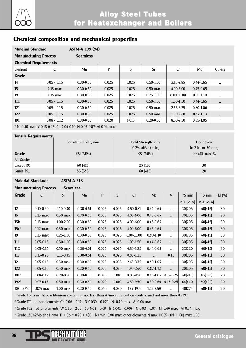
AlloAlloy Sy Stteel Teel Tubesubesffor Heator Heateexxcchanghanger and Boilerer and Boilerss
98 General catalogueGeneral catalogue
Material Standard ASTM-A 199 (94)
Manufacturing Process Seamless
Chemical Requirements
Element C Mn P S Si Cr Mo Others
Grade
T4 0.05 - 0.15 0.30-0.60 0.025 0.025 0.50-1.00 2.15-2.85 0.44-0.65 ...
T5 0.15 max 0.30-0.60 0.025 0.025 0.50 max 4.00-6.00 0.45-0.65 ...
T9 0.15 max 0.30-0.60 0.025 0.025 0.25-1.00 8.00-10.00 0.90-1.10 ...
T11 0.05 - 0.15 0.30-0.60 0.025 0.025 0.50-1.00 1.00-1.50 0.44-0.65 ...
T21 0.05 - 0.15 0.30-0.60 0.025 0.025 0.50 max 2.65-3.35 0.80-1.06 ...
T22 0.05 - 0.15 0.30-0.60 0.025 0.025 0.50 max 1.90-2.60 0.87-1.13 ...
T91 0.08 - 0.12 0.30-0.60 0.020 0.010 0.20-0.50 8.00-9.50 0.85-1.05 *
* Ni 0.40 max; V 0.18-0.25; Cb 0.06-0.10; N 0.03-0.07; Al 0.04 max
Chemical composition and mechanical properties
Tensile RequirementsTensile Strength, min Yield Strength, min Elongation
(0.2% offset), min, in 2 in. or 50 mm,
Grade KSI (MPa) KSI (MPa) (or 4D), min, %
All Grades
Except T91 60 [415] 25 [170] 30
Grade T91 85 [585] 60 [415] 20
Material Standard: ASTM A 213
Manufacturing Process Seamless
Grade C Si Mn P S Cr Mo V YS min TS min El (%)
KSI [MPa] KSI [MPa]
T2 0.10-0.20 0.10-0.30 0.30-0.61 0.025 0.025 0.50-0.81 0.44-0.65 ... 30[205] 60[415] 30
T5 0.15 max 0.50 max 0.30-0.60 0.025 0.025 4.00-6.00 0.45-0.65 ... 30[205] 60[415] 30
T5b 0.15 max 1.00-2.00 0.30-0.60 0.025 0.025 4.00-6.00 0.45-0.65 ... 30[205] 60[415] 30
T5c1 0.12 max 0.50 max 0.30-0.60 0.025 0.025 4.00-6.00 0.45-0.65 ... 30[205] 60[415] 30
T9 0.15 max 0.25-1.00 0.30-0.60 0.025 0.025 8.00-10.00 0.90-1.10 ... 30[205] 60[415] 30
T11 0.05-0.15 0.50-1.00 0.30-0.60 0.025 0.025 1.00-1.50 0.44-0.65 ... 30[205] 60[415] 30
T12 0.05-0.15 0.50 max 0.30-0.61 0.025 0.025 0.80-1.25 0.44-0.65 ... 32[220] 60[415] 30
T17 0.15-0.25 0.15-0.35 0.30-0.61 0.025 0.025 0.80-1.25 ... 0.15 30[205] 60[415] 30
T21 0.05-0.15 0.50 max 0.30-0.60 0.025 0.025 2.65-3.35 0.80-1.06 ... 30[205] 60[415] 30
T22 0.05-0.15 0.50 max 0.30-0.60 0.025 0.025 1.90-2.60 0.87-1.13 ... 30[205] 60[415] 30
T912 0.08-0.12 0.20-0.50 0.30-0.60 0.020 0.010 8.00-9.50 0.85-1.05 0.18-0.25 60[415] 85[585] 20
T923 0.07-0.13 0.50 max 0.30-0.60 0.020 0.010 8.50-9.50 0.30-0.60 0.15-0.25 64[440] 90[620] 20
18Cr-2Mo4 0.025 max 1.00 max 0.30-0.60 0.040 0.030 17.5-19.5 1.75-2.50 ... 40[275] 60[415] 201 Grade T5c shall have a titanium content of not less than 4 times the carbon content and not more than 0.70%.2 Grade T91 - other elements: Cb 0.06 - 0.10 • N 0.030 - 0.070 • Ni 0.40 max • Al 0.04 max.3 Grade T92 - other elements: W 1.50 - 2.00 • Cb 0.04 - 0.09 • B 0.001 - 0.006 • N 0.03 - 0.07 • Ni 0.40 max • Al 0.04 max.4 Grade 18Cr-2Mo shall have Ti + Cb = 0.20 + 4(C + N) min, 0.80 max, other elements N max 0.035 • (Ni + Cu) max 1.00.
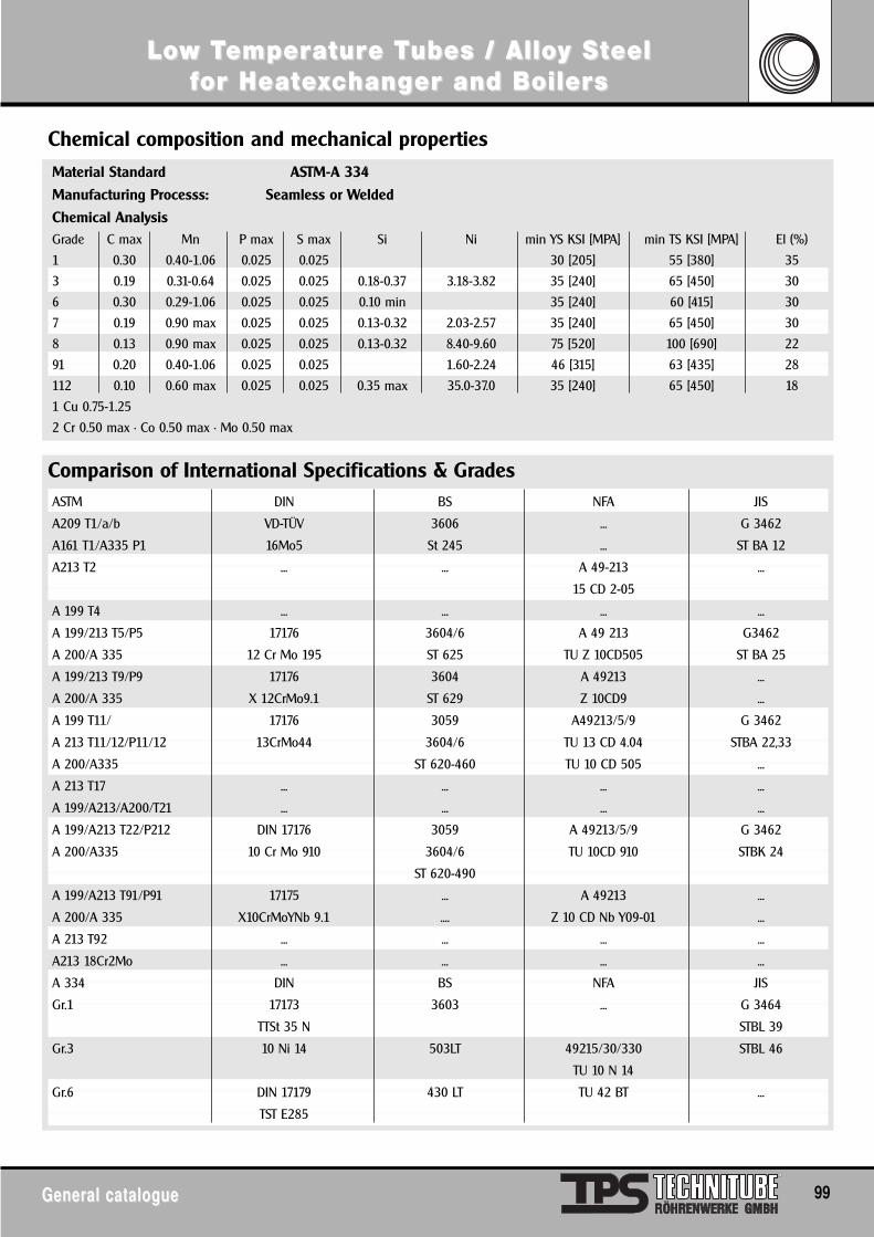
LoLow Tw Tememperperaturature Te Tubes / Alloubes / Alloy Sy Stteeleelffor Heator Heateexxcchanghanger and Boilerer and Boilerss
General catalogueGeneral catalogue 99
Chemical composition and mechanical propertiesMaterial Standard ASTM-A 334
Manufacturing Processs: Seamless or Welded
Chemical AnalysisGrade C max Mn P max S max Si Ni min YS KSI [MPA] min TS KSI [MPA] El (%)
1 0.30 0.40-1.06 0.025 0.025 30 [205] 55 [380] 35
3 0.19 0.31-0.64 0.025 0.025 0.18-0.37 3.18-3.82 35 [240] 65 [450] 30
6 0.30 0.29-1.06 0.025 0.025 0.10 min 35 [240] 60 [415] 30
7 0.19 0.90 max 0.025 0.025 0.13-0.32 2.03-2.57 35 [240] 65 [450] 30
8 0.13 0.90 max 0.025 0.025 0.13-0.32 8.40-9.60 75 [520] 100 [690] 22
91 0.20 0.40-1.06 0.025 0.025 1.60-2.24 46 [315] 63 [435] 28
112 0.10 0.60 max 0.025 0.025 0.35 max 35.0-37.0 35 [240] 65 [450] 18
1 Cu 0.75-1.25
2 Cr 0.50 max • Co 0.50 max • Mo 0.50 max
Comparison of International Specifications & GradesASTM DIN BS NFA JIS
A209 T1/a/b VD-TÜV 3606 ... G 3462
A161 T1/A335 P1 16Mo5 St 245 ... ST BA 12
A213 T2 ... ... A 49-213 ...
15 CD 2-05
A 199 T4 ... ... ... ...
A 199/213 T5/P5 17176 3604/6 A 49 213 G3462
A 200/A 335 12 Cr Mo 195 ST 625 TU Z 10CD505 ST BA 25
A 199/213 T9/P9 17176 3604 A 49213 ...
A 200/A 335 X 12CrMo9.1 ST 629 Z 10CD9 ...
A 199 T11/ 17176 3059 A49213/5/9 G 3462
A 213 T11/12/P11/12 13CrMo44 3604/6 TU 13 CD 4.04 STBA 22,33
A 200/A335 ST 620-460 TU 10 CD 505 ...
A 213 T17 ... ... ... ...
A 199/A213/A200/T21 ... ... ... ...
A 199/A213 T22/P212 DIN 17176 3059 A 49213/5/9 G 3462
A 200/A335 10 Cr Mo 910 3604/6 TU 10CD 910 STBK 24
ST 620-490
A 199/A213 T91/P91 17175 ... A 49213 ...
A 200/A 335 X10CrMoYNb 9.1 .... Z 10 CD Nb Y09-01 ...
A 213 T92 ... ... ... ...
A213 18Cr2Mo ... ... ... ...
A 334 DIN BS NFA JIS
Gr.1 17173 3603 ... G 3464
TTSt 35 N STBL 39
Gr.3 10 Ni 14 503LT 49215/30/330 STBL 46
TU 10 N 14
Gr.6 DIN 17179 430 LT TU 42 BT ...
TST E285
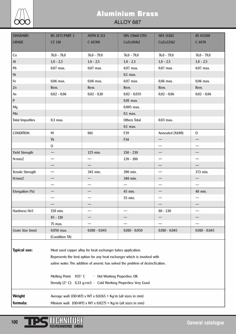
AluminiumAluminium BrBrass ass ALLOY 687
100 General catalogueGeneral catalogue
STANDARD BS 2871/PART 3 ASTM B 111 DIN 17660/1785 NFA 51102 JIS H3300
GRADE CZ 110 C 68700 CuZn20Al2 CuZn22Al2 C 6870
Cu 76,0 - 78,0 76,0 - 79,0 76,0 - 79,0 76,0 - 79,0 76,0 - 79,0
Al 1,8 - 2,3 1,8 - 2,5 1,8 - 2,3 1,8 - 2,5 1,8 - 2,5
Pb 0,07 max. 0,07 max 0,07 max. 0,07 max. 0,07 max.
Ni 0,1 max.
Fe 0,06 max. 0,06 max. 0,07 max. 0,06 max. 0,06 max.
Zn Rem. Rem. Rem. Rem. Rem.
As 0,02 - 0,06 0,02 - 0,10 0,02 - 0,035 0,02 - 0,06 0,02 - 0,06
P 0,01 max.
Mg 0,005 max.
Mn 0,1 max.
Total Impurities 0,3 max. Others Total 0,03 max.
0,1 max.
CONDITION M 061 F39 Annealed (X690) O
TA F34 — —
O — —
Yield Strength — 125 min. 150 - 230 — —
N/mm2 — — 120 - 180 — —
— — — —
Tensile Strength — 345 min. 390 min. — 373 min.
N/mm2 — — 340 min. — —
— — — — —
Elongation (%) — — 45 min. — 40 min.
— — 55 min. — —
— — — —
Hardness Hv5 150 min. — — 80 - 130 —
85 - 110 — — — —
75 max. — — — —
Grain Size (mm) 0,050 max. 0,010 - 0,045 0,010 - 0,050 0,010 - 0,045 0,010 - 0,045
(Condition TA)
Typical use: Most used copper alloy for heat exchanger tubes application.
Represents the best option for any heat exchanger which is involved with
saline water. The addition of arsenic has solved the problem of dezincfication.
Melting Point: 935° C • Hot Working Properties: OK
Density (2° C): 8,33 g/cm3 • Cold Working Properties: Very Good
Weight Average wall: (OD-WT) x WT x 0,0265 = Kg/m (all sizes in mm)
formula: Minium wall: (OD-WT) x WT x 0,0275 = Kg/m (all sizes in mm)
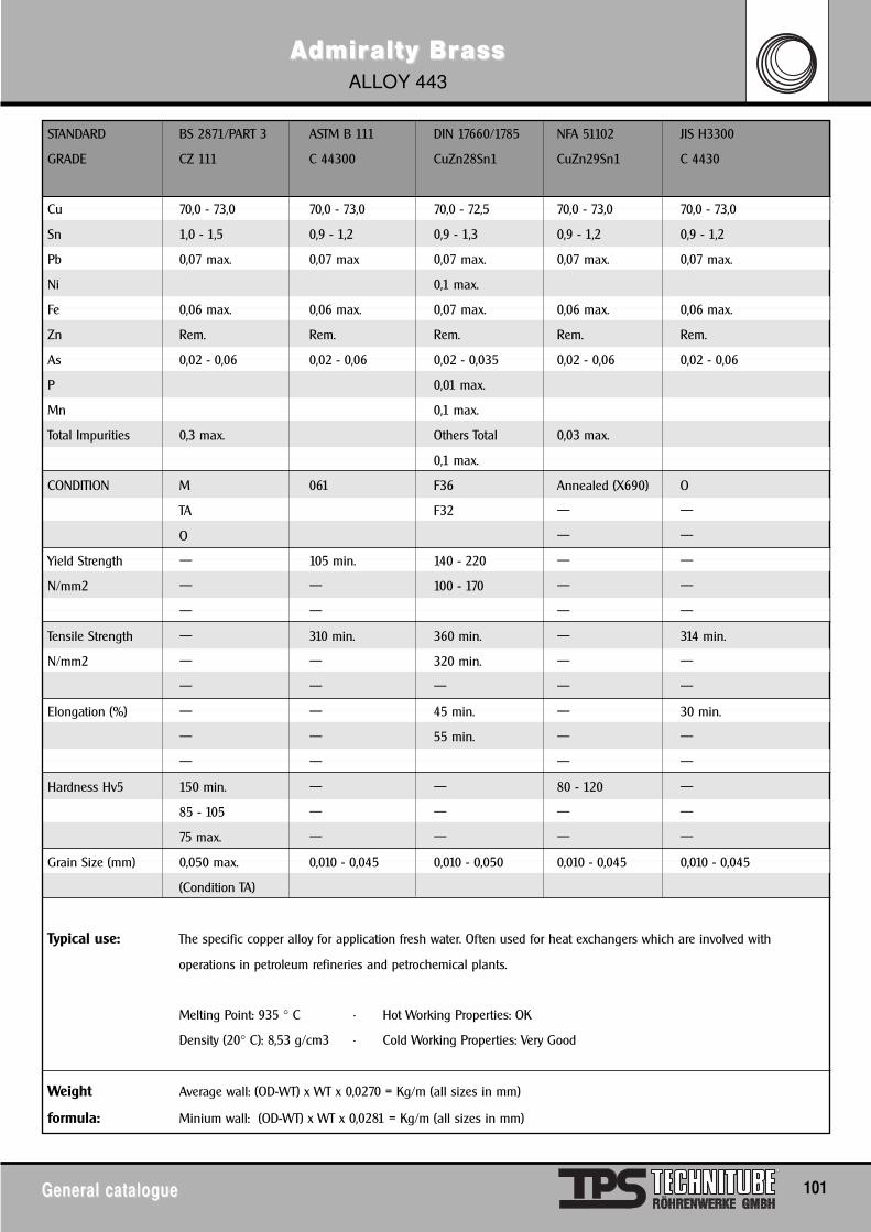
AAdmirdmiraltyalty BrBrass ass ALLOY 443
General catalogueGeneral catalogue 101
STANDARD BS 2871/PART 3 ASTM B 111 DIN 17660/1785 NFA 51102 JIS H3300
GRADE CZ 111 C 44300 CuZn28Sn1 CuZn29Sn1 C 4430
Cu 70,0 - 73,0 70,0 - 73,0 70,0 - 72,5 70,0 - 73,0 70,0 - 73,0
Sn 1,0 - 1,5 0,9 - 1,2 0,9 - 1,3 0,9 - 1,2 0,9 - 1,2
Pb 0,07 max. 0,07 max 0,07 max. 0,07 max. 0,07 max.
Ni 0,1 max.
Fe 0,06 max. 0,06 max. 0,07 max. 0,06 max. 0,06 max.
Zn Rem. Rem. Rem. Rem. Rem.
As 0,02 - 0,06 0,02 - 0,06 0,02 - 0,035 0,02 - 0,06 0,02 - 0,06
P 0,01 max.
Mn 0,1 max.
Total Impurities 0,3 max. Others Total 0,03 max.
0,1 max.
CONDITION M 061 F36 Annealed (X690) O
TA F32 — —
O — —
Yield Strength — 105 min. 140 - 220 — —
N/mm2 — — 100 - 170 — —
— — — —
Tensile Strength — 310 min. 360 min. — 314 min.
N/mm2 — — 320 min. — —
— — — — —
Elongation (%) — — 45 min. — 30 min.
— — 55 min. — —
— — — —
Hardness Hv5 150 min. — — 80 - 120 —
85 - 105 — — — —
75 max. — — — —
Grain Size (mm) 0,050 max. 0,010 - 0,045 0,010 - 0,050 0,010 - 0,045 0,010 - 0,045
(Condition TA)
Typical use: The specific copper alloy for application fresh water. Often used for heat exchangers which are involved with
operations in petroleum refineries and petrochemical plants.
Melting Point: 935 ° C • Hot Working Properties: OK
Density (20° C): 8,53 g/cm3 • Cold Working Properties: Very Good
Weight Average wall: (OD-WT) x WT x 0,0270 = Kg/m (all sizes in mm)
formula: Minium wall: (OD-WT) x WT x 0,0281 = Kg/m (all sizes in mm)
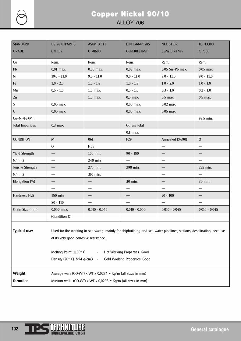
Copper NicCopper Nickkel 90/1el 90/100ALLOY 706
102 General catalogueGeneral catalogue
STANDARD BS 2871/PART 3 ASTM B 111 DIN 17664/1785 NFA 51102 JIS H3300
GRADE CN 102 C 70600 CuNi10Fe1Mn CuNi10Fe1Mn C 7060
Cu Rem. Rem. Rem. Rem. Rem.
Pb 0,01 max. 0,05 max. 0,03 max. 0,05 Sn+Pb max. 0,05 max.
Ni 10,0 - 11,0 9,0 - 11,0 9,0 - 11,0 9,0 - 11,0 9,0 - 11,0
Fe 1,0 - 2,0 1,0 - 1,8 1,0 - 1,8 1,0 - 2,0 1,0 - 1,8
Mn 0,5 - 1,0 1,0 max. 0,5 - 1,0 0,3 - 1,0 0,2 - 1,0
Zn 1,0 max. 0,5 max. 0,5 max. 0,5 max.
S 0,05 max. 0,05 max. 0,02 max.
C 0,05 max. 0,05 max. 0,05 max.
Cu+Ni+Fe+Mn 99,5 min.
Total Impurities 0,3 max. Others Total
0,1 max.
CONDITION M 061 F29 Annealed (X690) O
O H55 — —
Yield Strength — 105 min. 90 - 180 — —
N/mm2 — 240 min. — — —
Tensile Strength — 275 min. 290 min. — 275 min.
N/mm2 — 310 min. — —
Elongation (%) — — 30 min. — 30 min.
— — — — —
Hardness Hv5 150 min. — — 70 - 100 —
80 - 110 — — — —
Grain Size (mm) 0,050 max. 0,010 - 0,045 0,010 - 0,050 0,010 - 0,045 0,010 - 0,045
(Condition O)
Typical use: Used for the working in sea water, mainly for shipbuilding and sea water pipelines, stations, desalination, because
of its very good corrosive resistance.
Melting Point: 1150° C • Hot Working Properties: Good
Density (20° C): 8,94 g/cm3 • Cold Working Properties: Good
Weight Average wall: (OD-WT) x WT x 0,0284 = Kg/m (all sizes in mm)
formula: Minium wall: (OD-WT) x WT x 0,0295 = Kg/m (all sizes in mm)
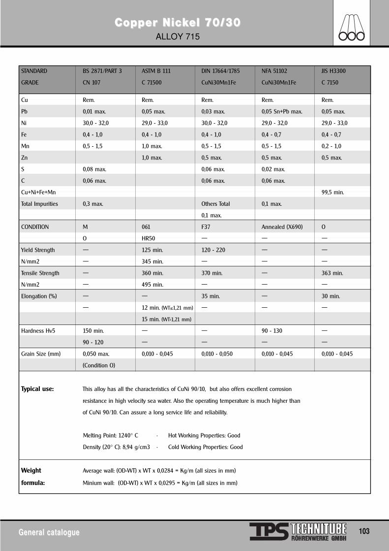
Copper NicCopper Nickkel 70/30el 70/30ALLOY 715
General catalogueGeneral catalogue 103
STANDARD BS 2871/PART 3 ASTM B 111 DIN 17664/1785 NFA 51102 JIS H3300
GRADE CN 107 C 71500 CuNi30Mn1Fe CuNi30Mn1Fe C 7150
Cu Rem. Rem. Rem. Rem. Rem.
Pb 0,01 max. 0,05 max. 0,03 max. 0,05 Sn+Pb max. 0,05 max.
Ni 30,0 - 32,0 29,0 - 33,0 30,0 - 32,0 29,0 - 32,0 29,0 - 33,0
Fe 0,4 - 1,0 0,4 - 1,0 0,4 - 1,0 0,4 - 0,7 0,4 - 0,7
Mn 0,5 - 1,5 1,0 max. 0,5 - 1,5 0,5 - 1,5 0,2 - 1,0
Zn 1,0 max. 0,5 max. 0,5 max. 0,5 max.
S 0,08 max. 0,06 max. 0,02 max.
C 0,06 max. 0,06 max. 0,06 max.
Cu+Ni+Fe+Mn 99,5 min.
Total Impurities 0,3 max. Others Total 0,1 max.
0,1 max.
CONDITION M 061 F37 Annealed (X690) O
O HR50 — — —
Yield Strength — 125 min. 120 - 220 — —
N/mm2 — 345 min. — — —
Tensile Strength — 360 min. 370 min. — 363 min.
N/mm2 — 495 min. — — —
Elongation (%) — — 35 min. — 30 min.
— 12 min. (WT≤1,21 mm) — — —
15 min. (WT>1,21 mm)
Hardness Hv5 150 min. — — 90 - 130 —
90 - 120 — — — —
Grain Size (mm) 0,050 max. 0,010 - 0,045 0,010 - 0,050 0,010 - 0,045 0,010 - 0,045
(Condition O)
Typical use: This alloy has all the characteristics of CuNi 90/10, but also offers excellent corrosion
resistance in high velocity sea water. Also the operating temperature is much higher than
of CuNi 90/10. Can assure a long service life and reliability.
Melting Point: 1240° C • Hot Working Properties: Good
Density (20° C): 8,94 g/cm3 • Cold Working Properties: Good
Weight Average wall: (OD-WT) x WT x 0,0284 = Kg/m (all sizes in mm)
formula: Minium wall: (OD-WT) x WT x 0,0295 = Kg/m (all sizes in mm)
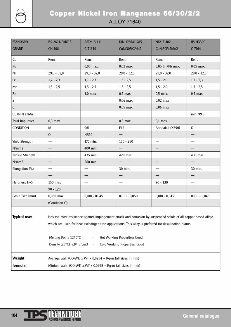
Copper NicCopper Nickkel Irel Iron Mangon Manganese 66/30/2/2anese 66/30/2/2ALLOY 71640
104 General catalogueGeneral catalogue
STANDARD BS 2871/PART 3 ASTM B 111 DIN 17664/1785 NFA 51102 JIS H3300
GRADE CN 108 C 71640 CuNi30Fe2Mn2 CuNi30Fe2Mn2 C 7164
Cu Rem. Rem. Rem. Rem. Rem.
Pb 0,05 max. 0,02 max. 0,05 Sn+Pb max. 0,05 max.
Ni 29,0 - 32,0 29,0 - 32,0 29,0 - 32,0 29,0 - 32,0 29,0 - 32,0
Fe 1,7 - 2,3 1,7 - 2,3 1,5 - 2,5 1,5 - 2,0 1,7 - 2,3
Mn 1,5 - 2,5 1,5 - 2,5 1,5 - 2,5 1,5 - 2,0 1,5 - 2,5
Zn 1,0 max. 0,5 max. 0,5 max. 0,5 max.
S 0,06 max. 0,02 max.
C 0,05 max. 0,06 max.
Cu+Ni+Fe+Mn min. 99,5
Total Impurities 0,3 max. 0,3 max. 0,1 max.
CONDITION M 061 F42 Annealed (X690) O
O HR50 — —
Yield Strength — 170 min. 150 - 260 — —
N/mm2 — 400 min. — — —
Tensile Strength — 435 min. 420 min. — 430 min.
N/mm2 — 560 min. — — —
Elongation (%) — — 30 min. — 30 min.
— — — — —
Hardness Hv5 150 min. — — 90 - 130 —
90 - 120 — — — —
Grain Size (mm) 0,050 max. 0,010 - 0,045 0,010 - 0,050 0,010 - 0,045 0,010 - 0,045
(Condition O)
Typical use: Has the most resistance against impingement attack and corrosion by suspended solids of all copper based alloys
which are used for heat exchanger tube applications. This alloy is preferred for desalination plants.
Melting Point: 1240°C • Hot Working Properties: Good
Density (20°C): 8,94 g/cm3 • Cold Working Properties: Good
Weight Average wall: (OD-WT) x WT x 0,0284 = Kg/m (all sizes in mm)
formula: Minium wall: (OD-WT) x WT x 0,0295 = Kg/m (all sizes in mm)

General catalogueGeneral catalogue 105
TPS - SHUTDOTPS - SHUTDOWN SERVICEWN SERVICE
TPS-Technitube Röhrenwerke GmbHJulius-Saxler-Straße 7 • Industriegebiet • D-54550 Daun, GermanyP.O. BOX 509 • D-54541 Daun, Germany
PHONE: (49) 6592 7120 • FAX: (49) 6592 1305E-MAIL: [email protected]: www.TPS-Technitube.de
Shutdown Service
TPS - SHUTDOWN SERVICE
TPS has increased the department for Refinery Shutdown- and Emergency Services.
This department is specialized in the supply of Heat-Exchanger and Condenser Tubes in
- Carbon Steel
- Alloy Steel
- Non Ferrous Metals
- Stainless Steel
- Nickel Alloys and
- Titanium
for urgent requirements and emergency purposes.
The material is either available ex stock for delivery within hours or from special new production within a very shortlead time.
"Just in time deliveries" is not only an idiom. It is proved that TPS has served a lot of refinieries with quick andexcellent deliveries. The result is a tremendous saving in costs and time for the endusers.
A further advantage is that the refinery or the petrochemical plant does not have to keep its own stock for shutdowns and maintenance periods.
As mentioned above, deliveries ex stock can be made within 24 hours during the week and within 48 hours duringthe weekend.
We have experience with this type of business and therefore we now offer our worldwide "Shutdown Service".
Furthermore we offer a complete service with yearly contracts and estimated quantities for all kinds of Heat-Exchanger tubes used in your plant.
In case you have special questions please do not hesitate to contact usby phone, by fax or by e-mail:
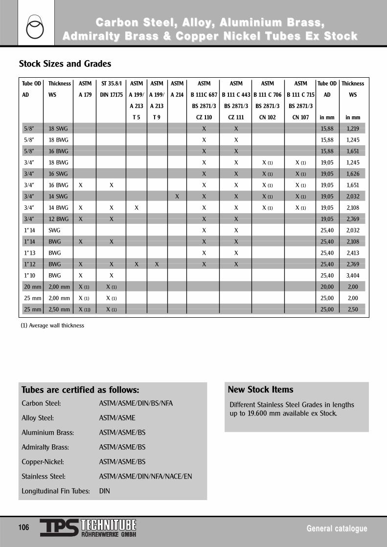
106 General catalogueGeneral catalogue
Carbon SCarbon Stteel, Alloeel, Alloyy, Aluminium Br, Aluminium Brass, ass, AAdmirdmiralty Bralty Brass & Copper Nicass & Copper Nickkel Tel Tubes Ex Subes Ex Sttocockk
Tube OD Thickness ASTM ST 35.8/I ASTM ASTM ASTM ASTM ASTM ASTM ASTM Tube OD Thickness
AD WS A 179 DIN 17175 A 199/ A 199/ A 214 B 111C 687 B 111 C 443 B 111 C 706 B 111 C 715 AD WS
A 213 A 213 BS 2871/3 BS 2871/3 BS 2871/3 BS 2871/3
T 5 T 9 CZ 110 CZ 111 CN 102 CN 107 in mm in mm
5/8" 18 SWG X X 15,88 1,219
5/8" 18 BWG X X 15,88 1,245
5/8" 16 BWG X X 15,88 1,651
3/4" 18 BWG X X X (1) X (1) 19,05 1,245
3/4" 16 SWG X X X (1) X (1) 19,05 1,626
3/4" 16 BWG X X X X X (1) X (1) 19,05 1,651
3/4" 14 SWG X X X X (1) X (1) 19,05 2,032
3/4" 14 BWG X X X X X X (1) X (1) 19,05 2,108
3/4" 12 BWG X X X X 19,05 2,769
1"14 SWG X X 25,40 2,032
1"14 BWG X X X X 25,40 2,108
1"13 BWG X X 25,40 2,413
1"12 BWG X X X X X X 25,40 2,769
1"10 BWG X X 25,40 3,404
20 mm 2,00 mm X (1) X (1) 20,00 2,00
25 mm 2,00 mm X (1) X (1) 25,00 2,00
25 mm 2,50 mm X (1)) X (1) 25,00 2,50
Stock Sizes and Grades
(1) Average wall thickness
New Stock Items
Different Stainless Steel Grades in lengthsup to 19.600 mm available ex Stock.
Tubes are certified as follows:Carbon Steel: ASTM/ASME/DIN/BS/NFA
Alloy Steel: ASTM/ASME
Aluminium Brass: ASTM/ASME/BS
Admiralty Brass: ASTM/ASME/BS
Copper-Nickel: ASTM/ASME/BS
Stainless Steel: ASTM/ASME/DIN/NFA/NACE/EN
Longitudinal Fin Tubes: DIN
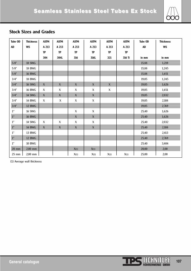
General catalogueGeneral catalogue 107
Seamless SSeamless Sttainless Sainless Stteel Teel Tubes Ex Subes Ex Sttocockk
Tube OD Thickness ASTM ASTM ASTM ASTM ASTM ASTM Tube OD Thickness
AD WS A 213 A 213 A 213 A 213 A 213 A 213 AD WS
TP TP TP TP TP TP
304 304L 316 316L 321 316 Ti in mm in mm
5/8" 18 SWG 15,88 1,219
5/8" 18 BWG 15,88 1,245
5/8" 16 BWG 15,88 1,651
3/4" 18 BWG 19,05 1,245
3/4" 16 SWG X X X X X 19,05 1,626
3/4" 16 BWG X X X X X 19,05 1,651
3/4" 14 SWG X X X X 19,05 2,032
3/4" 14 BWG X X X X 19,05 2,108
3/4" 12 BWG 19,05 2,769
1“ 16 SWG X X 25,40 1,626
1“ 16 BWG X X 25,40 1,626
1" 14 SWG X X X X 25,40 2,032
1" 14 BWG X X X X 25,40 2,108
1" 13 BWG 25,40 2,413
1" 12 BWG 25,40 2,769
1" 10 BWG 25,40 3,404
20 mm 2,00 mm X(1) X(1) 20,00 2,00
25 mm 2,00 mm X(1) X(1) X(1) X(1) 25,00 2,00
Stock Sizes and Grades
(1) Average wall thickness
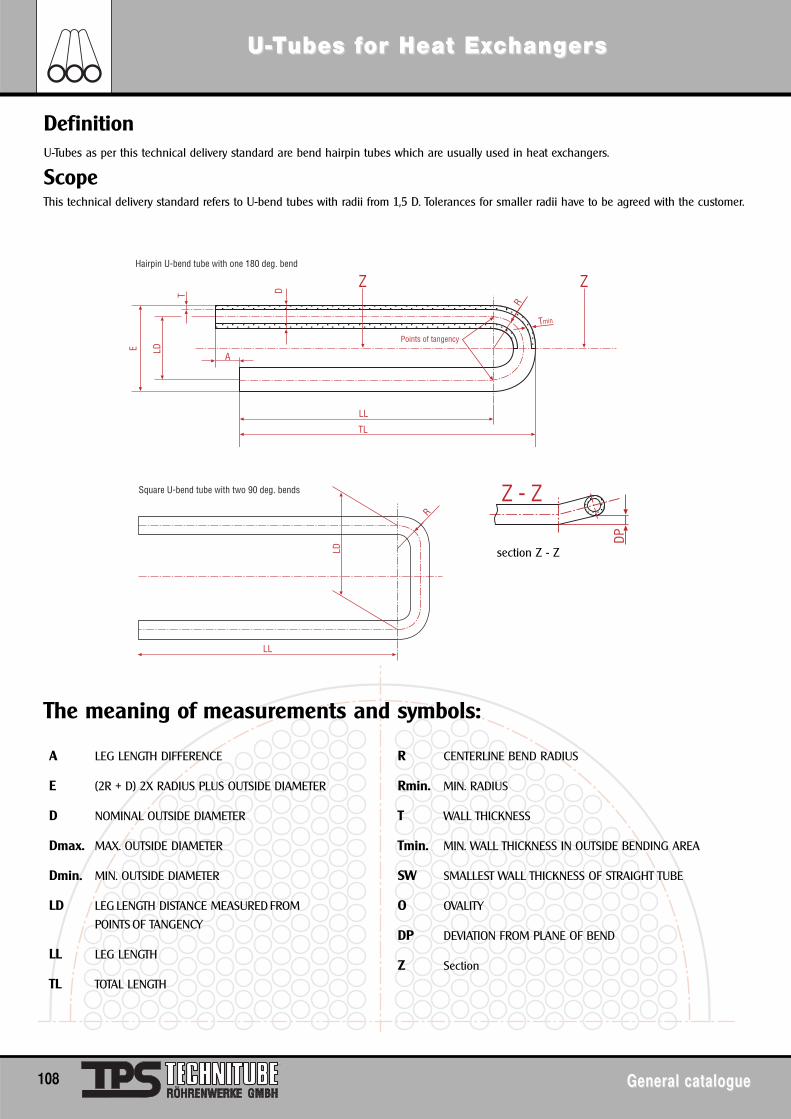
U-U-TTubes fubes for Heat Exor Heat Excchanghangererss
108 General catalogueGeneral catalogue
A LEG LENGTH DIFFERENCE
E (2R + D) 2X RADIUS PLUS OUTSIDE DIAMETER
D NOMINAL OUTSIDE DIAMETER
Dmax. MAX. OUTSIDE DIAMETER
Dmin. MIN. OUTSIDE DIAMETER
LD LEG LENGTH DISTANCE MEASURED FROM
POINTS OF TANGENCY
LL LEG LENGTH
TL TOTAL LENGTH
R CENTERLINE BEND RADIUS
Rmin. MIN. RADIUS
T WALL THICKNESS
Tmin. MIN. WALL THICKNESS IN OUTSIDE BENDING AREA
SW SMALLEST WALL THICKNESS OF STRAIGHT TUBE
O OVALITY
DP DEVIATION FROM PLANE OF BEND
Z Section
A
LDE
T DZ Z
R
Tmin
Hairpin U-bend tube with one 180 deg. bend
Points of tangency
TL
LL
Square U-bend tube with two 90 deg. bends
LD
R
LL
Z - Z
DP
DefinitionU-Tubes as per this technical delivery standard are bend hairpin tubes which are usually used in heat exchangers.
ScopeThis technical delivery standard refers to U-bend tubes with radii from 1,5 D. Tolerances for smaller radii have to be agreed with the customer.
section Z - Z
The meaning of measurements and symbols:
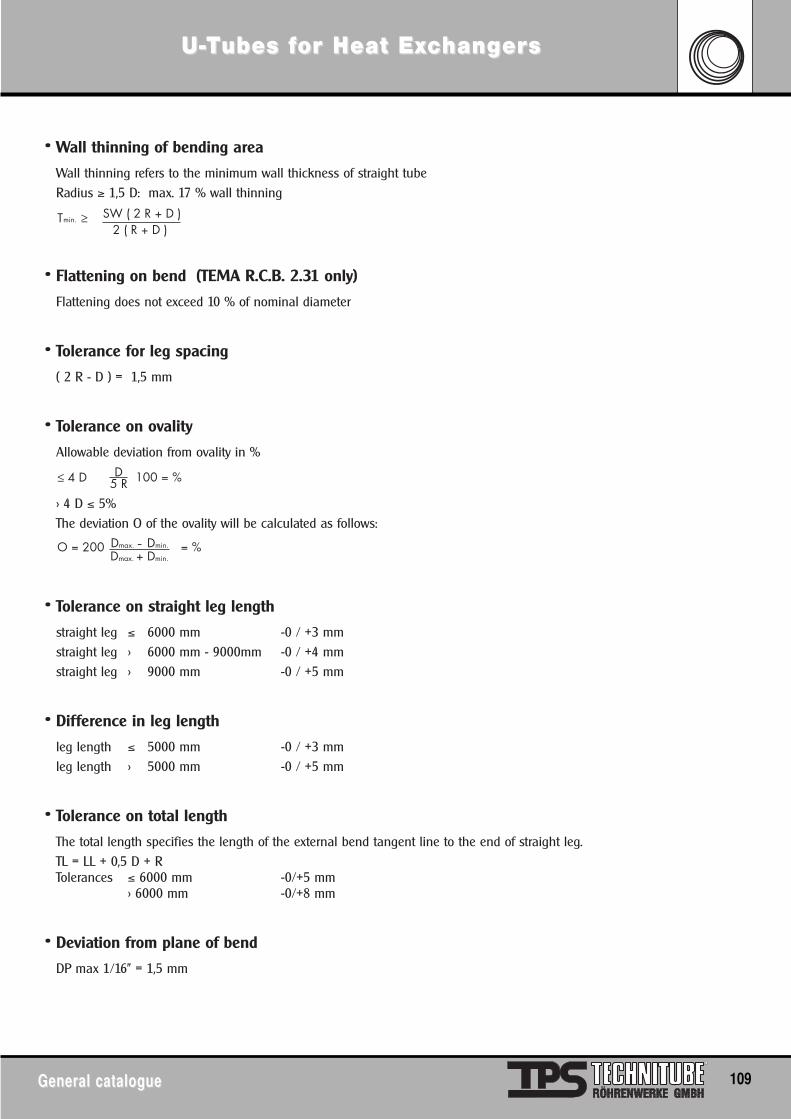
• Wall thinning of bending area
Wall thinning refers to the minimum wall thickness of straight tubeRadius ≥ 1,5 D: max. 17 % wall thinning
• Flattening on bend (TEMA R.C.B. 2.31 only)
Flattening does not exceed 10 % of nominal diameter
• Tolerance for leg spacing
( 2 R - D ) = 1,5 mm
• Tolerance on ovality
Allowable deviation from ovality in %
> 4 D ≤ 5%The deviation O of the ovality will be calculated as follows:
• Tolerance on straight leg length
straight leg ≤ 6000 mm -0 / +3 mmstraight leg > 6000 mm - 9000mm -0 / +4 mmstraight leg > 9000 mm -0 / +5 mm
• Difference in leg length
leg length ≤ 5000 mm -0 / +3 mmleg length > 5000 mm -0 / +5 mm
• Tolerance on total length
The total length specifies the length of the external bend tangent line to the end of straight leg.TL = LL + 0,5 D + RTolerances ≤ 6000 mm -0/+5 mm
> 6000 mm -0/+8 mm
• Deviation from plane of bend
DP max 1/16" = 1,5 mm
U-U-TTubes fubes for Heat Exor Heat Excchanghangererss
General catalogueGeneral catalogue 109
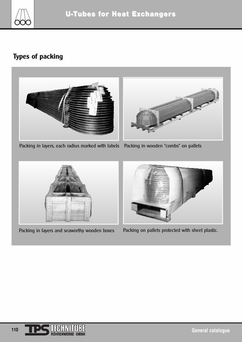
110 General catalogueGeneral catalogue
U-U-TTubes fubes for Heat Exor Heat Excchanghangererss
Packing in layers and seaworthy wooden boxes Packing on pallets protected with sheet plastic.
Packing in layers, each radius marked with labels
Types of packing
Packing in wooden “combs” on pallets
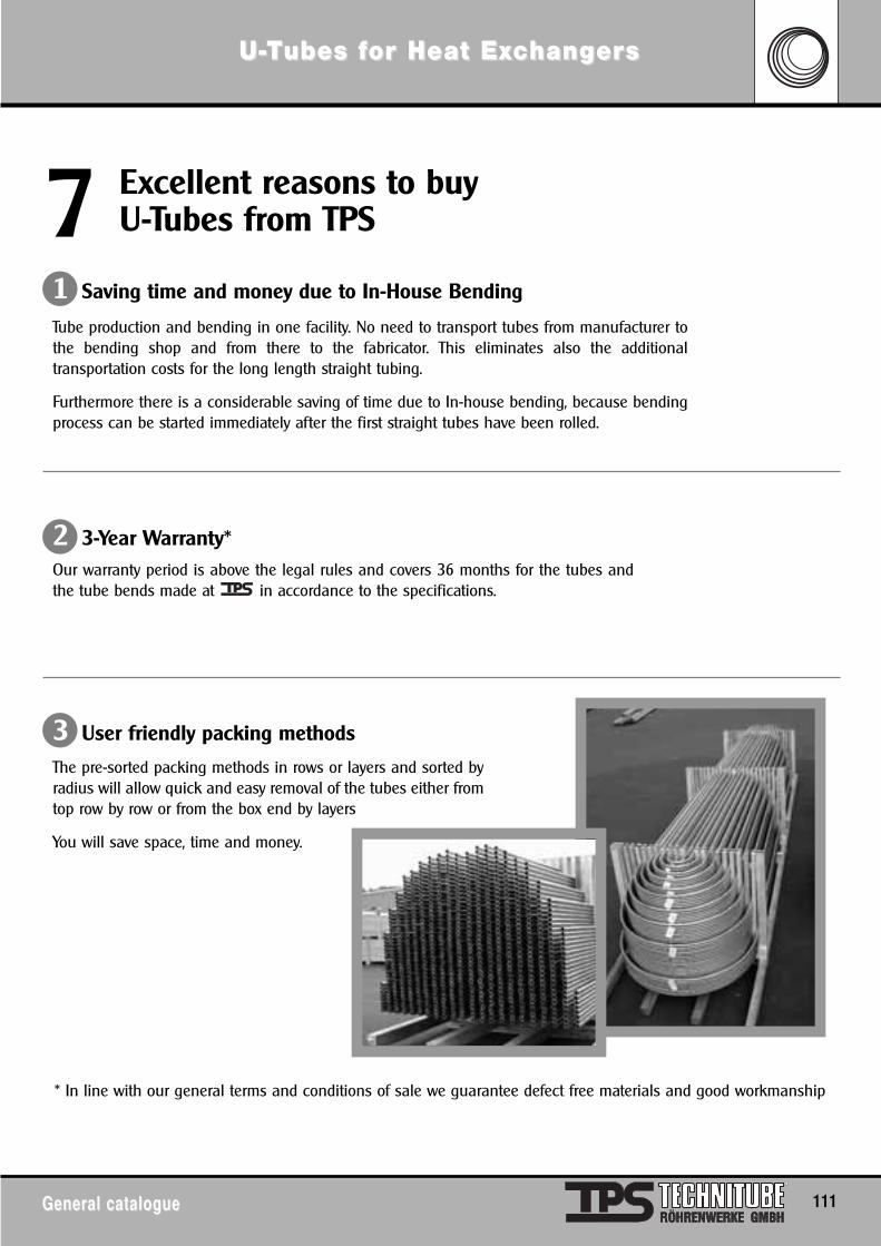
General catalogueGeneral catalogue 111
U-U-TTubes fubes for Heat Exor Heat Excchanghangererss
Tube production and bending in one facility. No need to transport tubes from manufacturer tothe bending shop and from there to the fabricator. This eliminates also the additionaltransportation costs for the long length straight tubing.
Furthermore there is a considerable saving of time due to In-house bending, because bendingprocess can be started immediately after the first straight tubes have been rolled.
Our warranty period is above the legal rules and covers 36 months for the tubes andthe tube bends made at in accordance to the specifications.
* In line with our general terms and conditions of sale we guarantee defect free materials and good workmanship
The pre-sorted packing methods in rows or layers and sorted byradius will allow quick and easy removal of the tubes either fromtop row by row or from the box end by layers
You will save space, time and money.
Excellent reasons to buy U-Tubes from TPSExcellent reasons to buyU-Tubes from TPS77
1 Saving time and money due to In-House Bending
2 3-Year Warranty*
3 User friendly packing methods
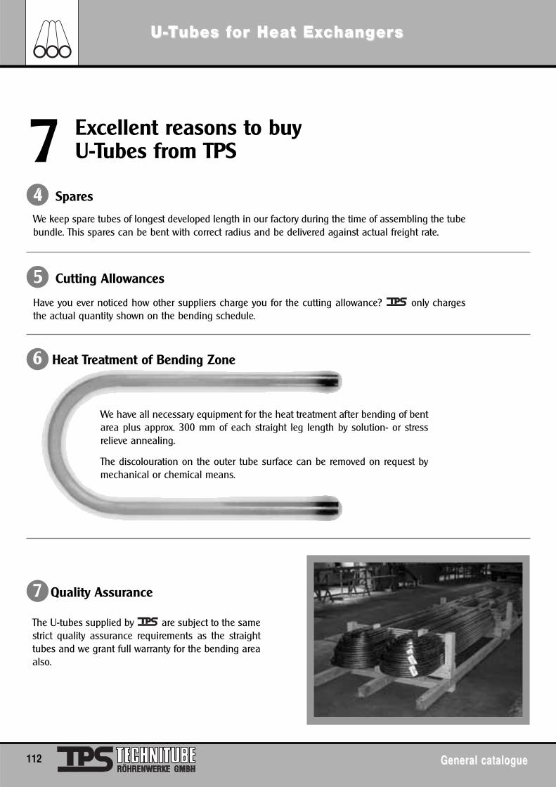
112 General catalogueGeneral catalogue
U-U-TTubes fubes for Heat Exor Heat Excchanghangererss
We keep spare tubes of longest developed length in our factory during the time of assembling the tubebundle. This spares can be bent with correct radius and be delivered against actual freight rate.
Excellent reasons to buy U-Tubes from TPSExcellent reasons to buyU-Tubes from TPS77
4 Spares
Have you ever noticed how other suppliers charge you for the cutting allowance? only chargesthe actual quantity shown on the bending schedule.
5 Cutting Allowances
We have all necessary equipment for the heat treatment after bending of bentarea plus approx. 300 mm of each straight leg length by solution- or stressrelieve annealing.
The discolouration on the outer tube surface can be removed on request bymechanical or chemical means.
The U-tubes supplied by are subject to the samestrict quality assurance requirements as the straighttubes and we grant full warranty for the bending areaalso.
6 Heat Treatment of Bending Zone
7 Quality Assurance
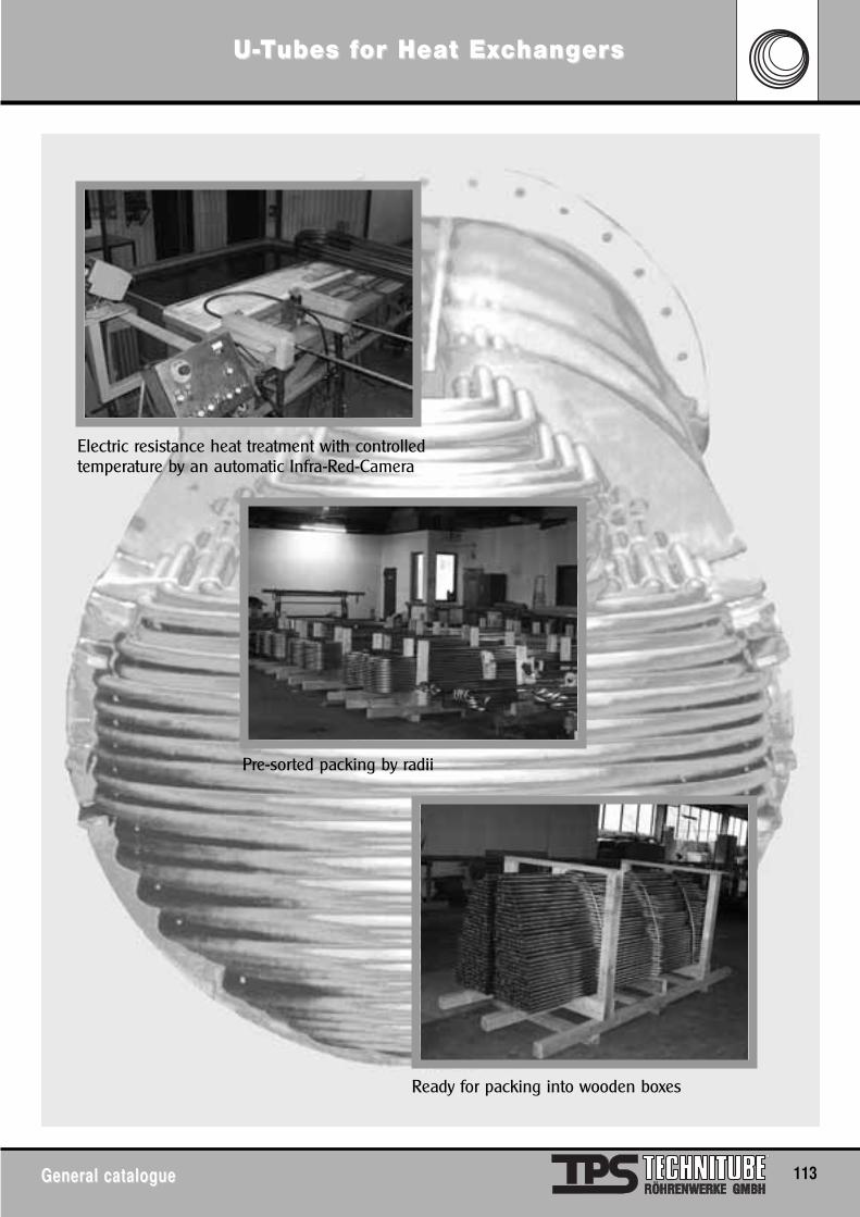
General catalogueGeneral catalogue 113
U-U-TTubes fubes for Heat Exor Heat Excchanghangererss
Electric resistance heat treatment with controlledtemperature by an automatic Infra-Red-Camera
Pre-sorted packing by radii
Ready for packing into wooden boxes
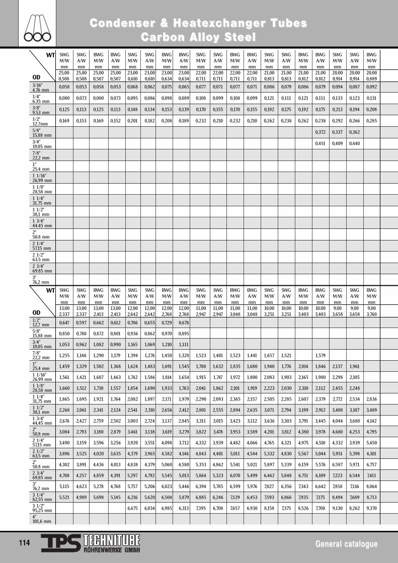
114 General catalogueGeneral catalogue
Condenser & HeatCondenser & Heateexxcchanghanger Ter Tubes ubes Carbon AlloCarbon Alloy Sy Stteeleel
3/16"4.76 mm1/4"6.35 mm3/8"9.53 mm1/2"12.7mm5/8"15,88 mm3/4"19,05 mm7/8"22,2 mm1"25.4 mm1 1/16"26,99 mm1 1/8"28,58 mm1 1/4"31.75 mm1 1/2"38,1 mm1 3/4"44.45 mm2"50.8 mm2 1/4"57.15 mm2 1/2"63.5 mm2 3/4"69.85 mm3"76,2 mm
0,058 0,053 0,058 0,053 0,068 0,062 0,075 0,065 0,077 0,071 0,077 0,071 0,086 0,079 0,086 0,079 0,094 0,087 0,092
0,080 0,073 0,080 0,073 0,095 0,086 0,098 0,089 0,108 0,099 0,108 0,099 0,121 0,111 0,121 0,111 0,133 0,123 0,131
0,125 0,113 0,125 0,113 0,148 0,134 0,153 0,139 0,170 0,155 0,170 0,155 0,192 0,175 0,192 0,175 0,213 0,194 0,208
0,169 0,153 0,169 0,152 0,201 0,182 0,208 0,189 0,232 0,210 0,232 0,210 0,262 0,238 0,262 0,238 0,292 0,266 0,285
0,372 0,337 0,362
0,451 0,409 0,440
SWG SWG BWG BWG SWG SWG BWG BWG SWG SWG BWG BWG SWG SWG BWG BWG SWG SWG BWGM/W A/W M/W A/W M/W A/W M/W A/W M/W A/W M/W A/W M/W A/W M/W A/W M/W A/W M/Wmm mm mm mm mm mm mm mm mm mm mm mm mm mm mm mm mm mm mm
13,00 13,00 13,00 13,00 12,00 12,00 12,00 12,00 11,00 11,00 11,00 11,00 10,00 10,00 10,00 10,00 9,00 9,00 9,002,337 2,337 2,413 2,413 2,642 2,642 2,768 2,768 2,947 2,947 3,048 3,048 3,251 3,251 3,403 3,403 3,658 3,658 3,760
1/2"12,7 mm5/8"15,88 mm 3/4"19,05 mm7/8"22,2 mm1"25,4 mm1 1/16"26,99 mm1 1/8"28,58 mm1 1/4"31,75 mm1 1/2"38,1 mm1 3/4"44,45 mm2"50,8 mm2 1/4"57,15 mm2 1/2"63,5 mm2"50.8 mm2 3/4"69,85 mm3"76,2 mm3 1/4"82,55 mm3 1/2"95,25 mm4"101,6 mm
0,647 0,597 0,662 0,612 0,706 0,655 0,729 0,678
0,850 0,780 0,872 0,801 0,936 0,862 0,970 0,895
1,053 0,962 1,082 0,990 1,165 1,069 1,210 1,111
1,255 1,146 1,290 1,179 1,394 1,276 1,450 1,328 1,523 1,401 1,523 1,441 1,657 1,521 1,579
1,459 1,329 1,502 1,368 1,624 1,483 1,691 1,545 1,780 1,632 1,835 1,680 1,940 1,776 2,014 1,846 2,137 1,961
1,561 1,421 1,607 1,463 1,742 1,586 1,814 1,654 1,915 1,747 1,972 1,800 2,083 1,903 2,165 1,980 2,298 2,105
1,660 1,512 1,710 1,557 1,854 1,690 1,933 1,763 2,041 1,862 2,101 1,919 2,223 2,030 2,310 2,112 2,455 2,248
1,865 1,695 1,921 1,764 2,082 1,897 2,171 1,979 2,290 2,093 2,365 2,157 2,505 2,285 2,607 2,379 2,772 2,534 2,836
2,268 2,061 2,341 2,124 2,541 2,310 2,656 2,412 2,801 2,555 2,894 2,635 3,071 2,794 3,199 2,912 3,408 3,107 3,489
2,676 2,427 2,759 2,502 3,003 2,724 3,137 2,845 3,311 3,015 3,423 3,112 3,636 3,303 3,791 3,445 4,044 3,680 4,142
3,084 2,793 3,180 2,879 3,461 3,138 3,619 3,279 3,822 3,478 3,953 3,589 4,201 3,812 4,380 3,978 4,680 4,253 4,795
3,490 3,159 3,596 3,256 3,920 3,551 4,098 3,712 4,332 3,939 4,482 4,066 4,765 4,321 4,975 4,510 4,332 3,939 5,450
3,896 3,525 4,020 3,635 4,379 3,965 4,582 4,146 4,843 4,401 5,011 4,544 5,332 4,830 5,567 5,044 5,951 5,398 6,101
4,302 3,891 4,436 4,013 4,838 4,379 5,060 4,580 5,353 4,862 5,541 5,021 5,897 5,339 6,159 5,576 6,587 5,971 6,757
4,708 4,257 4,859 4,391 5,297 4,792 5,545 5,013 5,864 5,323 6,070 5,499 6,462 5,848 6,751 6,109 7,223 6,544 7,411
5,115 4,623 5,278 4,768 5,757 5,206 6,023 5,446 6,394 5,785 6,599 5,976 7,027 6,356 7,343 6,642 7,858 7,116 8,064
5,521 4,989 5,698 5,145 6,216 5,620 6,504 5,879 6,885 6,246 7,129 6,453 7,593 6,866 7,935 7,175 8,494 7,689 8,713
6,675 6,034 6,985 6,313 7,395 6,708 7,657 6,930 8,158 7,375 8,526 7,708 9,130 8,262 9,370
SWG SWG BWG BWG SWG SWG BWG BWG SWG SWG BWG BWG SWG SWG BWG BWG SWG SWG BWGM/W A/W M/W A/W M/W A/W M/W A/W M/W A/W M/W A/W M/W A/W M/W A/W M/W A/W M/Wmm mm mm mm mm mm mm mm mm mm mm mm mm mm mm mm mm mm mm
25,00 25,00 25,00 25,00 23,00 23,00 23,00 23,00 22,00 22,00 22,00 22,00 21,00 21,00 21,00 21,00 20,00 20,00 20,000,508 0,508 0,507 0,507 0,610 0,610 0,634 0,634 0,711 0,711 0,711 0,711 0,813 0,813 0,812 0,812 0,914 0,914 0,889
WT
OD
WT
OD
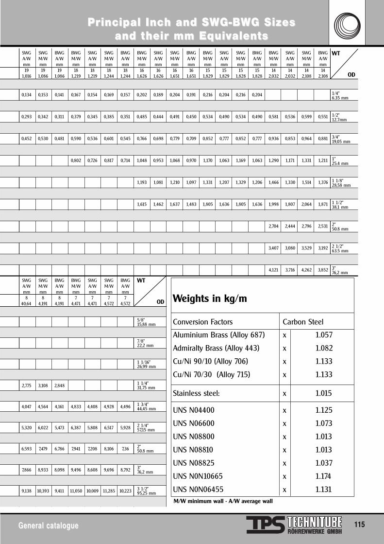
General catalogueGeneral catalogue 115
PrPrincipal Incincipal Inch and Sh and SWWG-BG-BWWG Sizes G Sizes and tand their mm Eqheir mm Equivuivalentsalents
3/16"4.76 mm1/4"6.35 mm3/8"9.53 mm1/2"12.7mm5/8"15,88 mm3/4"19,05 mm7/8"22,2 mm1"25.4 mm1 1/16"26,99 mm1 1/8"28,58 mm1 1/4"31.75 mm1 1/2"38,1 mm1 3/4"44.45 mm2"50.8 mm2 1/4"57.15 mm2 1/2"63.5 mm2 3/4"69.85 mm3"76,2 mm
0,094 0,106 0,089
0,134 0,153 0,141 0,167 0,154 0,169 0,157 0,202 0,189 0,204 0,191 0,216 0,204 0,216 0,204
0,213 0,247 0,226 0,273 0,250 0,278 0,254 0,344 0,317 0,348 0,321 0,375 0,347 0,375 0,347
0,293 0,342 0,311 0,379 0,345 0,385 0,351 0,485 0,444 0,491 0,450 0,534 0,490 0,534 0,490 0,581 0,536 0,599 0,551
0,372 0,436 0,396 0,485 0,441 0,494 0,449 0,626 0,572 0,635 0,579 0,693 0,634 0,693 0,633 0,758 0,694 0,781 0,716
0,452 0,530 0,481 0,590 0,536 0,601 0,545 0,766 0,698 0,779 0,709 0,852 0,777 0,852 0,777 0,936 0,853 0,964 0,881
0,696 0,631 0,709 0,643 0,909 0,826 0,919 0,836 1,010 0,919 1,009 0,918 1,112 1,012 1,147 1,045
0,802 0,726 0,817 0,714 1,048 0,953 1,068 0,970 1,170 1,063 1,169 1,063 1,290 1,171 1,331 1,211
1,121 1,017 1,137 1,032 1,251 1,135 1,250 1,134 1,377 1,251 1,424 1,294
1,193 1,081 1,210 1,097 1,331 1,207 1,329 1,206 1,466 1,330 1,514 1,376
1,333 1,208 1,350 1,225 1,487 1,349 1,487 1,349 1,644 1,489 1,697 1,541
1,615 1,462 1,637 1,483 1,805 1,636 1,805 1,636 1,998 1,807 2,064 1,871
2,351 2,126 2,430 2,201
2,704 2,444 2,796 2,531
3,054 2,762 3,163 2,861
3,407 3,080 3,529 3,192
3,761 3,399 3,896 3,522
4,121 3,716 4,262 3,852
1/2"12,7 mm5/8"15,88 mm 3/4"19,05 mm7/8"22,2 mm1"25,4 mm1 1/16"26,99 mm1 1/8"28,58 mm1 1/4"31,75 mm1 1/2"38,1 mm1 3/4"44,45 mm2"50,8 mm2 1/4"57,15 mm2 1/2"63,5 mm2"50.8 mm2 3/4"69,85 mm3"76,2 mm3 1/4"82,55 mm3 1/2"95,25 mm4"101,6 mm
2,137 2,192
2,775 3,108 2,848
3,411 3,836 3,505 4,055 3,708 4,133 3,780
4,047 4,564 4,161 4,833 4,408 4,928 4,496
4,684 5,292 4,817 5,610 5,108 5,717 5,212
5,320 6,022 5,473 6,387 5,808 6,517 5,928
5,957 6,751 6,130 7,164 6,508 7,312 6,644
6,593 7,479 6,786 7,941 7,208 8,106 7,36
7,229 8,208 7,442 8,718 7,908 8,901 8,076
7,866 8,933 8,098 9,496 8,608 9,696 8,792
8,502 9,661 8,755 10,273 9,308 10,491 9,508
9,138 10,393 9,411 11,050 10,009 11,285 10,223
9,775 11,122 10,066 11,827 10,709 12,080 10,939
SWG SWG BWG BWG SWG SWG BWG BWG SWG SWG BWG BWG SWG SWG BWG BWG SWG SWG BWGA/W M/W A/W M/W A/W M/W A/W M/W A/W M/W A/W M/W A/W M/W A/W M/W A/W M/W A/Wmm mm mm mm mm mm mm mm mm mm mm mm mm mm mm mm mm mm mm19 19 19 18 18 18 18 16 16 16 16 15 15 15 15 14 14 14 14
1,016 1,086 1,086 1,219 1,219 1,244 1,244 1,626 1,626 1,651 1,651 1,829 1,829 1,828 1,828 2,032 2,032 2,108 2,108
WT
OD
WT
OD Weights in kg/m
Conversion Factors Carbon Steel
Aluminium Brass (Alloy 687) x 1.057
Admiralty Brass (Alloy 443) x 1.082
Cu/Ni 90/10 (Alloy 706) x 1.133
Cu/Ni 70/30 (Alloy 715) x 1.133
Stainless steel: x 1.015
UNS N04400 x 1.125
UNS N06600 x 1.073
UNS N08800 x 1.013
UNS N08810 x 1.013
UNS N08825 x 1.037
UNS N0N10665 x 1.174
UNS N0N06455 x 1.131
SWG SWG BWG BWG SWG SWG BWGA/W M/W A/W M/W A/W M/W A/Wmm mm mm mm mm mm mm8 8 8 7 7 7 7
40,64 4,191 4,191 4,471 4,471 4,572 4,572
M/W minimum wall • A/W average wall
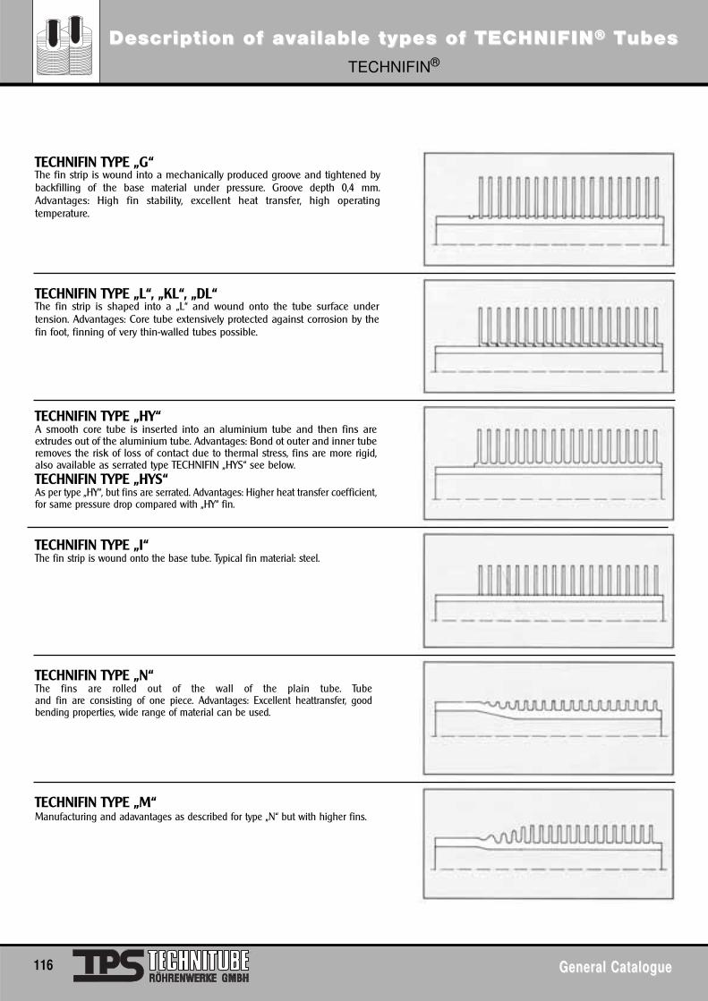
DescrDescripiption of ation of avvailable types of TECailable types of TECHNIFINHNIFIN®® TTubesubesTECHNIFIN®
116 General CatalogueGeneral Catalogue
TECHNIFIN TYPE „G“The fin strip is wound into a mechanically produced groove and tightened bybackfilling of the base material under pressure. Groove depth 0,4 mm.Advantages: High fin stability, excellent heat transfer, high operatingtemperature.
TECHNIFIN TYPE „L“, „KL“, „DL“The fin strip is shaped into a „L“ and wound onto the tube surface undertension. Advantages: Core tube extensively protected against corrosion by thefin foot, finning of very thin-walled tubes possible.
TECHNIFIN TYPE „I“The fin strip is wound onto the base tube. Typical fin material: steel.
TECHNIFIN TYPE „N“The fins are rolled out of the wall of the plain tube. Tubeand fin are consisting of one piece. Advantages: Excellent heattransfer, goodbending properties, wide range of material can be used.
TECHNIFIN TYPE „M“Manufacturing and adavantages as described for type „N“ but with higher fins.
TECHNIFIN TYPE „HY“A smooth core tube is inserted into an aluminium tube and then fins areextrudes out of the aluminium tube. Advantages: Bond ot outer and inner tuberemoves the risk of loss of contact due to thermal stress, fins are more rigid,also available as serrated type TECHNIFIN „HYS“ see below.TECHNIFIN TYPE „HYS“As per type „HY“, but fins are serrated. Advantages: Higher heat transfer coefficient,for same pressure drop compared with „HY“ fin.
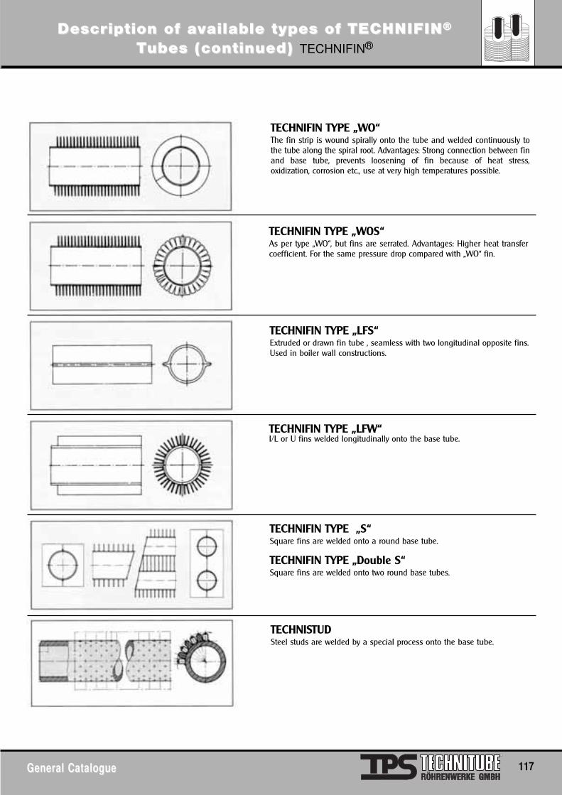
DescrDescripiption of ation of avvailable types of TECailable types of TECHNIFINHNIFIN®®
TTubes (continued) ubes (continued) TECHNIFIN®
General CatalogueGeneral Catalogue 117
TECHNIFIN TYPE „WO“The fin strip is wound spirally onto the tube and welded continuously tothe tube along the spiral root. Advantages: Strong connection between finand base tube, prevents loosening of fin because of heat stress,oxidization, corrosion etc., use at very high temperatures possible.
TECHNIFIN TYPE „WOS“As per type „WO“, but fins are serrated. Advantages: Higher heat transfercoefficient. For the same pressure drop compared with „WO“ fin.
TECHNIFIN TYPE „LFS“Extruded or drawn fin tube , seamless with two longitudinal opposite fins.Used in boiler wall constructions.
TECHNIFIN TYPE „LFW“I/L or U fins welded longitudinally onto the base tube.
TECHNIFIN TYPE „S“Square fins are welded onto a round base tube.
TECHNIFIN TYPE „Double S“Square fins are welded onto two round base tubes.
TECHNISTUD Steel studs are welded by a special process onto the base tube.
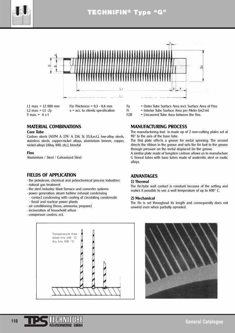
TECTECHNIFINHNIFIN®® TType “G”ype “G”
118 General CatalogueGeneral Catalogue
MATERIAL COMBINATIONSCore TubeCarbon steels (ASTM A 179/ A 214, St 35.8,ect.), low-alloy steels,stainless steels, copper-nickel alloys, aluminium bronze, copper,nickel-alloys (Alloy 400, etc.), bimetal
FinsAluminium / Steel / Galvanized Steel
FIELDS OF APPLICATION• the petroleum, chemical and petrochemical process industries• natural gas treatment• the steel industry: blast furnace and converter systems• power generation: steam turbine exhaust condensing
- contact condensing with cooling of circulating condensate- fossil and nuclear power plants
• air conditioning (freon, ammonia, propane)• incineration of household refuse• compressor coolers, ect.
MANUFACTURING PROCESSThe manufacturing tool is made up of 2 non-cutting plates set at90° to the axis of the base tube.The first plate effects a groove for metal spinning. The seconddirects the ribbon in the groove and sets the fin foot in the groovethrough pressure on the metal displaced for the groove.A similar plate made of tungsten carbure allows us to manufactureG finned tubes with base tubes made of austenitic steel or exoticalloys.
ADVANTAGES1) ThermalThe fin/tube wall contact is constant because of the setting andmakes it possible to use a wall temperature of up to 400° C.
2) MechanicalThe fin is set throughout its length and consequently does notunwind even when partially uprooted.
L1 max. = 12 000 mm Fin Thickness = 0,3 - 0,4 mm Fa = Outer Tube Surface Area incl. Surface Area of FinsL2 max. = L1 -2y x = acc. to clients specification Fi = Interior Tube Surface Area per Meter (m2/m)Y max. = 4 x t FZR = Uncovered Tube Area between the fins
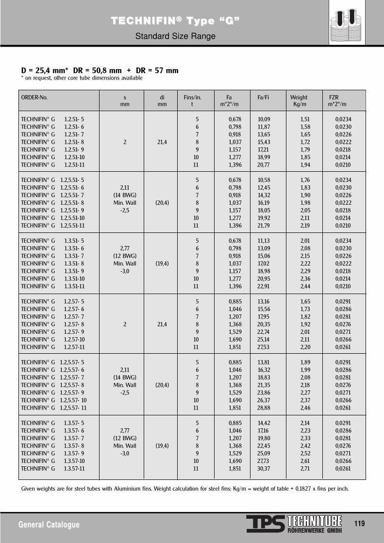
TECTECHNIFINHNIFIN®® TType “G”ype “G”Standard Size Range
General CatalogueGeneral Catalogue 119
ORDER-No. s di Fins/in. Fa Fa/Fi Weight FZRmm mm t m*2*/m Kg/m m*2*/m
TECHNIFIN® G 1.2.51- 5 5 0,678 10,09 1,51 0,0234TECHNIFIN® G 1.2.51- 6 6 0,798 11,87 1,58 0,0230TECHNIFIN® G 1.2.51- 7 7 0,918 13,65 1,65 0,0226TECHNIFIN® G 1.2.51- 8 2 21,4 8 1,037 15,43 1,72 0,0222TECHNIFIN® G 1.2.51- 9 9 1,157 17,21 1,79 0,0218TECHNIFIN® G 1.2.51-10 10 1,277 18,99 1,85 0,0214TECHNIFIN® G 1.2.51-11 11 1,396 20,77 1,94 0,0210
TECHNIFIN® G 1.2,5.51- 5 5 0,678 10,58 1,76 0,0234TECHNIFIN® G 1.2,5.51- 6 2,11 6 0,798 12,45 1,83 0,0230TECHNIFIN® G 1.2,5.51- 7 (14 BWG) 7 0,918 14,32 1,90 0,0226TECHNIFIN® G 1.2,5.51- 8 Min. Wall (20,4) 8 1,037 16,19 1,98 0,0222TECHNIFIN® G 1.2,5.51- 9 -2,5 9 1,157 18,05 2,05 0,0218TECHNIFIN® G 1.2,5.51-10 10 1,277 19,92 2,11 0,0214TECHNIFIN® G 1.2,5.51-11 11 1,396 21,79 2,19 0,0210
TECHNIFIN® G 1.3.51- 5 5 0,678 11,13 2,01 0,0234TECHNIFIN® G 1.3.51- 6 2,77 6 0,798 13,09 2,08 0,0230TECHNIFIN® G 1.3.51- 7 (12 BWG) 7 0,918 15,06 2,15 0,0226TECHNIFIN® G 1.3.51- 8 Min. Wall (19,4) 8 1,037 17,02 2,22 0,0222TECHNIFIN® G 1.3.51- 9 -3,0 9 1,157 18,98 2,29 0,0218TECHNIFIN® G 1.3.51-10 10 1,277 20,95 2,36 0,0214TECHNIFIN® G 1.3.51-11 11 1,396 22,91 2,44 0,0210
TECHNIFIN® G 1.2.57- 5 5 0,885 13,16 1,65 0,0291TECHNIFIN® G 1.2.57- 6 6 1,046 15,56 1,73 0,0286TECHNIFIN® G 1.2.57- 7 7 1,207 17,95 1,82 0,0281TECHNIFIN® G 1.2.57- 8 2 21,4 8 1,368 20,35 1,92 0,0276TECHNIFIN® G 1.2.57- 9 9 1,529 22,74 2,01 0,0271TECHNIFIN® G 1.2.57-10 10 1,690 25,14 2,11 0,0266TECHNIFIN® G 1.2.57-11 11 1,851 27,53 2,20 0,0261
TECHNIFIN® G 1.2,5.57- 5 5 0,885 13,81 1,89 0,0291TECHNIFIN® G 1.2,5.57- 6 2,11 6 1,046 16,32 1,99 0,0286TECHNIFIN® G 1.2,5.57- 7 (14 BWG) 7 1,207 18,83 2,08 0,0281TECHNIFIN® G 1.2,5.57- 8 Min. Wall (20,4) 8 1,368 21,35 2,18 0,0276TECHNIFIN® G 1.2,5.57- 9 -2,5 9 1,529 23,86 2,27 0,0271TECHNIFIN® G 1.2,5.57- 10 10 1,690 26,37 2,37 0,0266TECHNIFIN® G 1.2,5.57- 11 11 1,851 28,88 2,46 0,0261
TECHNIFIN® G 1.3.57- 5 5 0,885 14,42 2,14 0,0291TECHNIFIN® G 1.3.57- 6 2,77 6 1,046 17,16 2,23 0,0286TECHNIFIN® G 1.3.57- 7 (12 BWG) 7 1,207 19,80 2,33 0,0281TECHNIFIN® G 1.3.57- 8 Min. Wall (19,4) 8 1,368 22,45 2,42 0,0276TECHNIFIN® G 1.3.57- 9 -3,0 9 1,529 25,09 2,52 0,0271TECHNIFIN® G 1.3.57-10 10 1,690 27,73 2,61 0,0266TECHNIFIN® G 1.3.57-11 11 1,851 30,37 2,71 0,0261
Given weights are for steel tubes with Aluminium fins. Weight calculation for steel fins: Kg/m ≈ weight of table + 0,1827 x fins per inch.
D = 25,4 mm* DR = 50,8 mm + DR = 57 mm* on request, other core tube dimensions available
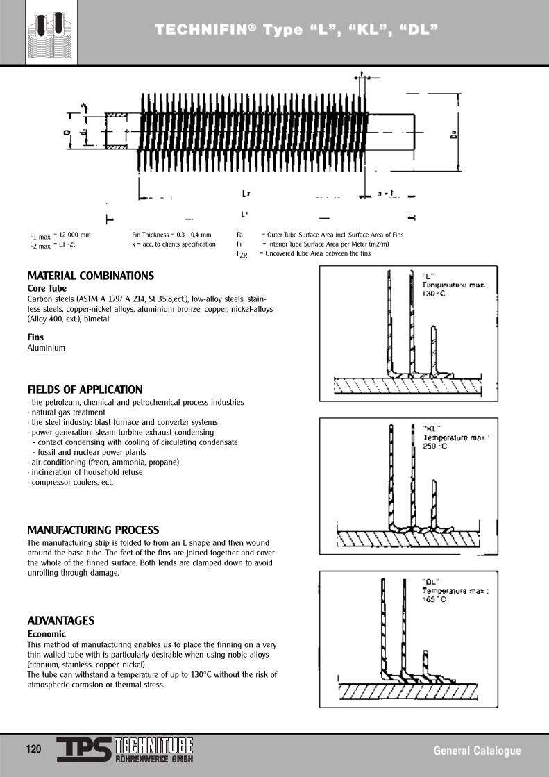
TECTECHNIFINHNIFIN®® TType “L”, “KL”, “DL”ype “L”, “KL”, “DL”
120 General CatalogueGeneral Catalogue
MATERIAL COMBINATIONSCore TubeCarbon steels (ASTM A 179/ A 214, St 35.8,ect.), low-alloy steels, stain-less steels, copper-nickel alloys, aluminium bronze, copper, nickel-alloys(Alloy 400, ext.), bimetal
FinsAluminium
FIELDS OF APPLICATION• the petroleum, chemical and petrochemical process industries• natural gas treatment• the steel industry: blast furnace and converter systems• power generation: steam turbine exhaust condensing
- contact condensing with cooling of circulating condensate- fossil and nuclear power plants
• air conditioning (freon, ammonia, propane)• incineration of household refuse• compressor coolers, ect.
MANUFACTURING PROCESSThe manufacturing strip is folded to from an L shape and then woundaround the base tube. The feet of the fins are joined together and coverthe whole of the finned surface. Both lends are clamped down to avoidunrolling through damage.
ADVANTAGESEconomicThis method of manufacturing enables us to place the finning on a verythin-walled tube with is particularly desirable when using noble alloys(titanium, stainless, copper, nickel).The tube can withstand a temperature of up to 130°C without the risk ofatmospheric corrosion or thermal stress.
L1 max. = 12 000 mm Fin Thickness = 0,3 - 0,4 mm Fa = Outer Tube Surface Area incl. Surface Area of FinsL2 max. = L1 -2t x = acc. to clients specification Fi = Interior Tube Surface Area per Meter (m2/m)
FZR = Uncovered Tube Area between the fins
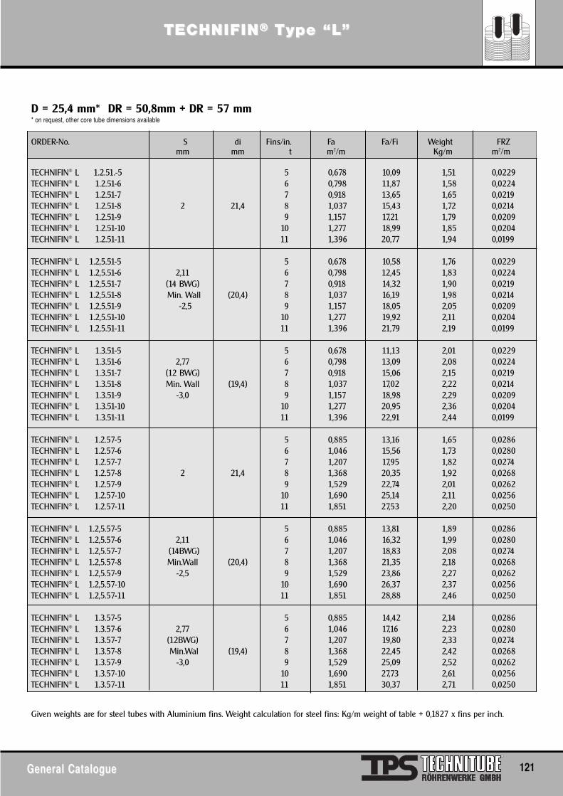
TECTECHNIFINHNIFIN®® TType “L”ype “L”
General CatalogueGeneral Catalogue 121
ORDER-No. S di Fins/in. Fa Fa/Fi Weight FRZmm mm t m2/m Kg/m m2/m
TECHNIFIN® L 1.2.51.-5 5 0,678 10,09 1,51 0,0229TECHNIFIN® L 1.2.51-6 6 0,798 11,87 1,58 0,0224TECHNIFIN® L 1.2.51-7 7 0,918 13,65 1,65 0,0219TECHNIFIN® L 1.2.51-8 2 21,4 8 1,037 15,43 1,72 0,0214TECHNIFIN® L 1.2.51-9 9 1,157 17,21 1,79 0,0209TECHNIFIN® L 1.2.51-10 10 1,277 18,99 1,85 0,0204TECHNIFIN® L 1.2.51-11 11 1,396 20,77 1,94 0,0199
TECHNIFIN® L 1.2,5.51-5 5 0,678 10,58 1,76 0,0229TECHNIFIN® L 1.2,5.51-6 2,11 6 0,798 12,45 1,83 0,0224TECHNIFIN® L 1.2,5.51-7 (14 BWG) 7 0,918 14,32 1,90 0,0219TECHNIFIN® L 1.2,5.51-8 Min. Wall (20,4) 8 1,037 16,19 1,98 0,0214TECHNIFIN® L 1.2,5.51-9 -2,5 9 1,157 18,05 2,05 0,0209TECHNIFIN® L 1.2,5.51-10 10 1,277 19,92 2,11 0,0204TECHNIFIN® L 1.2,5.51-11 11 1,396 21,79 2,19 0,0199
TECHNIFIN® L 1.3.51-5 5 0,678 11,13 2,01 0,0229TECHNIFIN® L 1.3.51-6 2,77 6 0,798 13,09 2,08 0,0224TECHNIFIN® L 1.3.51-7 (12 BWG) 7 0,918 15,06 2,15 0,0219TECHNIFIN® L 1.3.51-8 Min. Wall (19,4) 8 1,037 17,02 2,22 0,0214TECHNIFIN® L 1.3.51-9 -3,0 9 1,157 18,98 2,29 0,0209TECHNIFIN® L 1.3.51-10 10 1,277 20,95 2,36 0,0204TECHNIFIN® L 1.3.51-11 11 1,396 22,91 2,44 0,0199
TECHNIFIN® L 1.2.57-5 5 0,885 13,16 1,65 0,0286TECHNIFIN® L 1.2.57-6 6 1,046 15,56 1,73 0,0280TECHNIFIN® L 1.2.57-7 7 1,207 17,95 1,82 0,0274TECHNIFIN® L 1.2.57-8 2 21,4 8 1,368 20,35 1,92 0,0268TECHNIFIN® L 1.2.57-9 9 1,529 22,74 2,01 0,0262TECHNIFIN® L 1.2.57-10 10 1,690 25,14 2,11 0,0256TECHNIFIN® L 1.2.57-11 11 1,851 27,53 2,20 0,0250
TECHNIFIN® L 1.2,5.57-5 5 0,885 13,81 1,89 0,0286TECHNIFIN® L 1.2,5.57-6 2,11 6 1,046 16,32 1,99 0,0280TECHNIFIN® L 1.2,5.57-7 (14BWG) 7 1,207 18,83 2,08 0,0274TECHNIFIN® L 1.2,5.57-8 Min.Wall (20,4) 8 1,368 21,35 2,18 0,0268TECHNIFIN® L 1.2,5.57-9 -2,5 9 1,529 23,86 2,27 0,0262TECHNIFIN® L 1.2,5.57-10 10 1,690 26,37 2,37 0,0256TECHNIFIN® L 1.2,5.57-11 11 1,851 28,88 2,46 0,0250
TECHNIFIN® L 1.3.57-5 5 0,885 14,42 2,14 0,0286TECHNIFIN® L 1.3.57-6 2,77 6 1,046 17,16 2,23 0,0280TECHNIFIN® L 1.3.57-7 (12BWG) 7 1,207 19,80 2,33 0,0274TECHNIFIN® L 1.3.57-8 Min.Wal (19,4) 8 1,368 22,45 2,42 0,0268TECHNIFIN® L 1.3.57-9 -3,0 9 1,529 25,09 2,52 0,0262TECHNIFIN® L 1.3.57-10 10 1,690 27,73 2,61 0,0256TECHNIFIN® L 1.3.57-11 11 1,851 30,37 2,71 0,0250
Given weights are for steel tubes with Aluminium fins. Weight calculation for steel fins: Kg/m weight of table + 0,1827 x fins per inch.
D = 25,4 mm* DR = 50,8mm + DR = 57 mm* on request, other core tube dimensions available
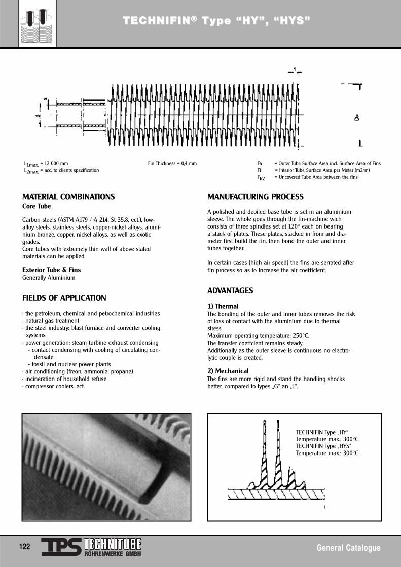
TECTECHNIFINHNIFIN®® TType “HY”, “HYype “HY”, “HYS”S”
122 General CatalogueGeneral Catalogue
MATERIAL COMBINATIONSCore Tube
Carbon steels (ASTM A179 / A 214, St 35.8, ect.), low-alloy steels, stainless steels, copper-nickel alloys, alumi-nium bronze, copper, nickel-alloys, as well as exoticgrades.Core tubes with extremely thin wall of above stated materials can be applied.
Exterior Tube & FinsGenerally Aluminium
FIELDS OF APPLICATION
• the petroleum, chemical and petrochemical industries• natural gas treatment• the steel industry: blast furnace and converter cooling
systems• power generation: steam turbine exhaust condensing
- contact condensing with cooling of circulating con-densate
- fossil and nuclear power plants• air conditioning (freon, ammonia, propane)• incineration of household refuse• compressor coolers, ect.
MANUFACTURING PROCESS
A polished and deoiled base tube is set in an aluminiumsleeve. The whole goes through the fin-machine wichconsists of three spindles set at 120° each on bearinga stack of plates. These plates, stacked in from and dia-meter first build the fin, then bond the outer and innertubes together.
In certain cases (high air speed) the fins are serrated afterfin process so as to increase the air coefficient.
ADVANTAGES
1) ThermalThe bonding of the outer and inner tubes removes the riskof loss of contact with the aluminium due to thermalstress.Maximum operating temperature: 250°C.The transfer coeffcient remains steady.Additionally as the outer sleeve is continuous no electro-lytic couple is created.
2) MechanicalThe fins are more rigid and stand the handling shocksbetter, compared to types „G“ an „L“.
L1max. = 12 000 mm Fin Thickness = 0,4 mm Fa = Outer Tube Surface Area incl. Surface Area of FinsL2max. = acc. to clients specification Fi = Interior Tube Surface Area per Meter (m2/m)
FRZ = Uncovered Tube Area between the fins
TECHNIFIN Type „HY“Temperature max.: 300°CTECHNIFIN Type „HYS“Temperature max.: 300°C
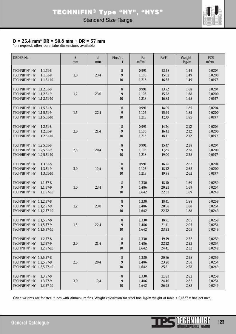
TECTECHNIFINHNIFIN®® TType “HY”, “HYype “HY”, “HYS”S”Standard Size Range
General CatalogueGeneral Catalogue 123
ORDER-No. S di Fins/in. Fa Fa/Fi Weight FZRmm mm t m2/m Kg/m m2/m
TECHNIFIN® HY 1.1.51-8 8 0,991 13,48 1,49 0,0204TECHNIFIN® HY 1.1.51-9 1,0 23,4 9 1,105 15,02 1,49 0,0200TECHNIFIN® HY 1.1.51-10 10 1,218 16,56 1,49 0,0197
TECHNIFIN® HY 1.1,2.51-8 8 0,991 13,72 1,68 0,0204TECHNIFIN® HY 1.1,2.51-9 1,2 23,0 9 1,105 15,28 1,68 0,0200TECHNIFIN® HY 1.1,2.51-10 10 1,218 16,85 1,68 0,0197
TECHNIFIN® HY 1.1,5.51-8 8 0,991 14,09 1,85 0,0204TECHNIFIN® HY 1.1,5.51-9 1,5 22,4 9 1,105 15,69 1,85 0,0200TECHNIFIN® HY 1.1,5.51-10 10 1,218 17,30 1,85 0,0197
TECHNIFIN® HY 1.2.51-8 8 0,991 14,74 2,12 0,0204TECHNIFIN® HY 1.2.51-9 2,0 21,4 9 1,105 16,43 2,12 0,0200TECHNIFIN® HY 1.2.51-10 10 1,218 18,11 2,12 0,0197
TECHNIFIN® HY 1.2,5.51-8 8 0,991 15,47 2,38 0,0204TECHNIFIN® HY 1.2,5.51-9 2,5 20,4 9 1,105 17,23 2,38 0,0200TECHHIFIN® HY 1.2,5.51-10 10 1,218 19,00 2,38 0,0197
TECHNIFIN® HY 1.3.51-8 8 0,991 16,26 2,62 0,0204TECHNIFIN® HY 1.3.51-9 3,0 19,4 9 1,105 18,12 2,62 0,0200TECHNIFIN® HY 1.3.51-10 10 1,218 19,98 2,62 0,0197
TECHNIFIN® HY 1.1.57-8 8 1,330 18,10 1,69 0,0259TECHNIFIN® HY 1.1.57-9 1,0 23,4 9 1,486 20,23 1,69 0,0254TECHNIFIN® HY 1.1.57-10 10 1,642 22,33 1,69 0,0249
TECHNIFIN® HY 1.1,2.57-8 8 1,330 18,41 1,88 0,0259TECHNIFIN® HY 1.1,2.57-9 1,2 23,0 9 1,486 20,58 1,88 0,0254TECHNIFIN® HY 1.1,2.57-10 10 1,642 22,72 1,88 0,0249
TECHNIFIN® HY 1.1,5.57-8 8 1,330 18,91 2,05 0,0259TECHNIFIN® HY 1.1,5.57-9 1,5 22,4 9 1,486 21,11 2,05 0,0254TECHNIFIN® HY 1.1,5.57-10 10 1,642 23,33 2,05 0,0249
TECHNIFIN® HY 1.2.57-8 8 1,330 19,79 2,32 0,0259TECHNIFIN® HY 1.2.57-9 2,0 21,4 9 1,486 22,12 2,32 0,0254TECHINFIN® HY 1.2.57-10 10 1,642 24,41 2,32 0,0249
TECHNIFIN® HY 1.2,5.57-8 8 1,330 20,76 2,58 0,0259TECHNIFIN® HY 1.2,5.57-9 2,5 20,4 9 1,486 23,20 2,58 0,0254TECHNIFIN® HY 1.2,5.57-10 10 1,642 25,61 2,58 0,0249
TECHNIFIN® HY 1.3.57-8 8 1,330 21,83 2,82 0,0259TECHNIFIN® HY 1.3.57-9 3,0 19,4 9 1,486 24,40 2,82 0,0254TECHNIFIN® HY 1.3.57-10 10 1,642 26,93 2,82 0,0249
Given weights are for steel tubes with Aluminium fins. Weight calculation for steel fins: Kg/m weight of table + 0,1827 x fins per inch.
D = 25,4 mm* DR = 50,8 mm + DR = 57 mm*on request, other core tube dimensions available

TECTECHNIFINHNIFIN®® TType “I”ype “I”
124 General CatalogueGeneral Catalogue
Size Range
Base tube size: 6-219.1 (other sizes upon request)Fins: 50-500 fins/meterFin thickness: 0.4-1.5 mm
Fin quantity and size depend on diameter of base tube. In case ofdeviation against the sizes of the opposite page, please ask us.
Tolerances: Fin height: +/- 1mmFins/meter: +/- 2%/meterPlain ends: +/- 5mm
Manufacturing Process
Fins are spirally wound on a steel base tube, without welding/sol-dering.Execution: black, galvanized and for special applications StainlessSteel, Copper, Brass, and/or Aluminium.Ends can be bevelled, bended or spot welded upon request.
Fields of application
Climatic Industry, CoolingHeating, Drying
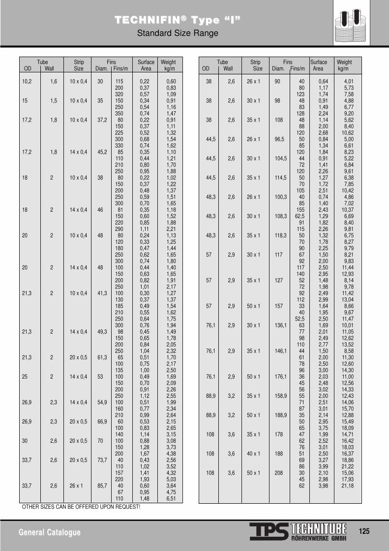
TECTECHNIFINHNIFIN®® TType “I”ype “I”Standard Size Range
General CatalogueGeneral Catalogue 125
Tube Strip Fins Surface Weight Tube Strip Fins Surface WeightOD Wall Size Diam. Fins/m Area kg/m OD Wall Size Diam. Fins/m Area kg/m
10,2 1,6 10 x 0,4 30 115 0,22 0,60 38 2,6 26 x 1 90 40 0,64 4,01200 0,37 0,83 80 1,17 5,73320 0,57 1,09 123 1,74 7,58
15 1,5 10 x 0,4 35 150 0,34 0,91 38 2,6 30 x 1 98 48 0,91 4,88250 0,54 1,16 83 1,49 6,77350 0,74 1,47 128 2,24 9,20
17,2 1,8 10 x 0,4 37,2 80 0,22 0,91 38 2,6 35 x 1 108 48 1,14 5,62150 0,37 1,11 88 2,00 8,40225 0,52 1,32 120 2,68 10,62300 0,68 1,54 44,5 2,6 26 x 1 96,5 50 0,84 5,00330 0,74 1,62 85 1,34 6,61
17,2 1,8 14 x 0,4 45,2 85 0,35 1,10 120 1,84 8,23110 0,44 1,21 44,5 2,6 30 x 1 104,5 44 0,91 5,22210 0,80 1,70 72 1,41 6,84250 0,95 1,88 120 2,26 9,61
18 2 10 x 0,4 38 80 0,22 1,02 44,5 2,6 35 x 1 114,5 50 1,27 6,38150 0,37 1,22 70 1,72 7,85200 0,48 1,37 105 2,51 10,42250 0,59 1,51 48,3 2,6 26 x 1 100,3 40 0,74 4,86300 0,70 1,65 85 1,40 7,02
18 2 14 x 0,4 46 81 0,35 1,18 155 2,43 10,37150 0,60 1,52 48,3 2,6 30 x 1 108,3 62,5 1,29 6,69220 0,85 1,88 91 1,82 8,40290 1,11 2,21 115 2,26 9,81
20 2 10 x 0,4 48 80 0,24 1,13 48,3 2,6 35 x 1 118,3 50 1,32 6,75120 0,33 1,25 70 1,78 8,27180 0,47 1,44 90 2,25 9,79250 0,62 1,65 57 2,9 30 x 1 117 67 1,50 8,21300 0,74 1,80 92 2,00 9,83
20 2 14 x 0,4 48 100 0,44 1,40 117 2,50 11,44150 0,63 1,65 140 2,95 12,93200 0,82 1,91 57 2,9 35 x 1 127 52 1,48 8,14250 1,01 2,17 72 1,98 9,78
21,3 2 10 x 0,4 41,3 100 0,30 1,27 92 2,49 11,42130 0,37 1,37 112 2,99 13,04185 0,49 1,54 57 2,9 50 x 1 157 33 1,64 8,66210 0,55 1,62 40 1,95 9,67250 0,64 1,75 52,5 2,50 11,47300 0,76 1,94 76,1 2,9 30 x 1 136,1 63 1,69 10,01
21,3 2 14 x 0,4 49,3 98 0,45 1,49 77 2,01 11,05150 0,65 1,78 98 2,49 12,62200 0,84 2,05 110 2,77 13,52250 1,04 2,32 76,1 2,9 35 x 1 146,1 44 1,50 8,58
21,3 2 20 x 0,5 61,3 65 0,51 1,70 61 2,00 11,30100 0,75 2,17 78 2,50 12,60135 1,00 2,50 96 3,00 14,30
25 2 14 x 0,4 53 100 0,49 1,69 76,1 2,9 50 x 1 176,1 36 2,03 11,00150 0,70 2,09 45 2,48 12,56200 0,91 2,26 56 3,02 14,33250 1,12 2,55 88,9 3,2 35 x 1 158,9 55 2,00 12,43
26,9 2,3 14 x 0,4 54,9 100 0,51 1,99 71 2,51 14,06160 0,77 2,34 87 3,01 15,70210 0,99 2,64 88,9 3,2 50 x 1 188,9 35 2,14 12,88
26,9 2,3 20 x 0,5 66,9 60 0,53 2,15 50 2,95 15,49100 0,83 2,65 65 3,75 18,09140 1,14 3,15 108 3,6 35 x 1 178 47 1,99 14,71
30 2,6 20 x 0,5 70 100 0,88 3,08 62 2,52 16,42150 1,28 3,73 76 3,01 18,03200 1,67 4,38 108 3,6 40 x 1 188 51 2,50 16,37
33,7 2,6 20 x 0,5 73,7 40 0,43 2,56 69 3,27 18,86110 1,02 3,52 86 3,99 21,22157 1,41 4,32 108 3,6 50 x 1 208 30 2,10 15,06220 1,93 5,03 45 2,98 17,93
33,7 2,6 26 x 1 85,7 40 0,60 3,64 62 3,98 21,1867 0,95 4,75
110 1,48 6,51OTHER SIZES CAN BE OFFERED UPON REQUEST!
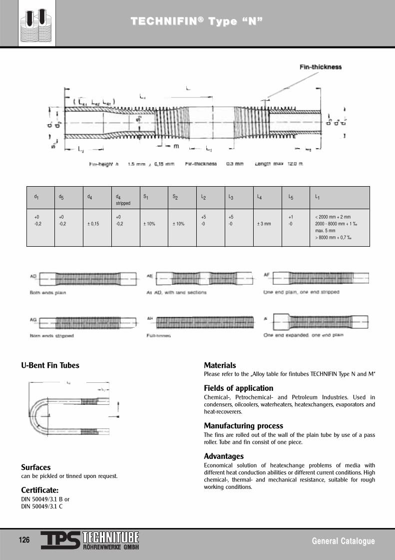
126 General CatalogueGeneral Catalogue
U-Bent Fin Tubes
Surfacescan be pickled or tinned upon request.
Certificate:DIN 50049/3.1 B orDIN 50049/3.1 C
MaterialsPlease refer to the „Alloy table for fintubes TECHNIFIN Type N and M“
Fields of applicationChemical-, Petrochemical- and Petroleum Industries. Used incondensers, oilcoolers, waterheaters, heatexchangers, evaporators andheat-recoverers.
Manufacturing processThe fins are rolled out of the wall of the plain tube by use of a passroller. Tube and fin consist of one piece.
AdvantagesEconomical solution of heatexchange problems of media withdifferent heat conduction abilities or different current conditions. Highchemical-, thermal- and mechanical resistance, suitable for roughworking conditions.
d1 d5 d4 d4 S1 S2 L2 L3 L4 L5 L1stripped
+0 +0 +0 +5 +5 +1 < 2000 mm + 2 mm-0,2 -0,2 ± 0,15 -0,2 ± 10% ± 10% -0 -0 ± 3 mm -0 2000 - 8000 mm + 1 ‰
max. 5 mm> 8000 mm + 0,7 ‰
TECTECHNIFINHNIFIN®® TType “N”ype “N”
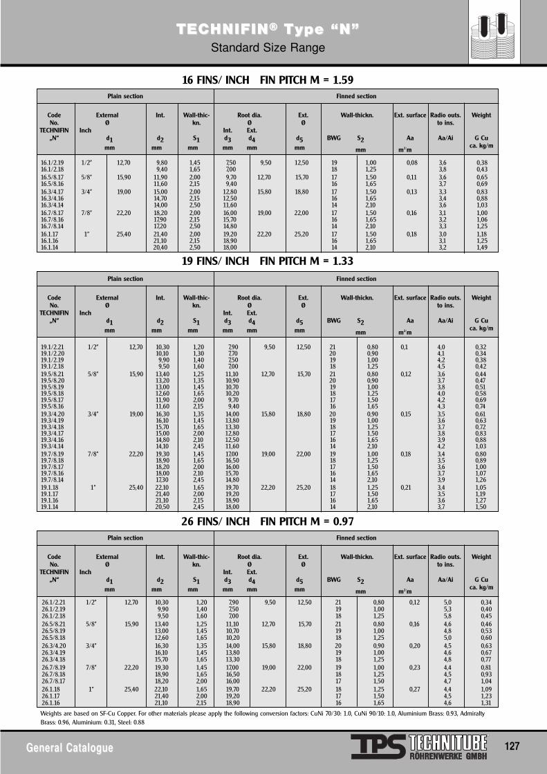
General CatalogueGeneral Catalogue 127
TECTECHNIFINHNIFIN®® TType “N”ype “N”Standard Size Range
16.1/2.19 1/2" 12,70 9,80 1,45 7,50 9,50 12,50 19 1,00 0,08 3,6 0,3816.1/2.18 9,40 1,65 7,00 18 1,25 3,8 0,4316.5/8.17 5/8" 15,90 11,90 2,00 9,70 12,70 15,70 17 1,50 0,11 3,6 0,6516.5/8.16 11,60 2,15 9,40 16 1,65 3,7 0,6916.3/4.17 3/4" 19,00 15,00 2,00 12,80 15,80 18,80 17 1,50 0,13 3,3 0,8316.3/4.16 14,70 2,15 12,50 16 1,65 3,4 0,8816.3/4.14 14,00 2,50 11,60 14 2,10 3,6 1,0316.7/8.17 7/8" 22,20 18,20 2,00 16,00 19,00 22,00 17 1,50 0,16 3,1 1,0016.7/8.16 17,90 2,15 15,70 16 1,65 3,2 1,0616.7/8.14 17,20 2,50 14,80 14 2,10 3,3 1,2516.1.17 1" 25,40 21,40 2,00 19,20 22,20 25,20 17 1,50 0,18 3,0 1,1816.1.16 21,10 2,15 18,90 16 1,65 3,1 1,2516.1.14 20,40 2,50 18,00 14 2,10 3,2 1,49
19.1/2.21 1/2" 12,70 10,30 1,20 7,90 9,50 12,50 21 0,80 0,1 4,0 0,3219.1/2.20 10,10 1,30 7,70 20 0,90 4,1 0,3419.1/2.19 9,90 1,40 7,50 19 1,00 4,2 0,3819.1/2.18 9,50 1,60 7,00 18 1,25 4,5 0,4219.5/8.21 5/8" 15,90 13,40 1,25 11,10 12,70 15,70 21 0,80 0,12 3,6 0,4419.5/8.20 13,20 1,35 10,90 20 0,90 3,7 0,4719.5/8.19 13,00 1,45 10,70 19 1,00 3,8 0,5119.5/8.18 12,60 1,65 10,20 18 1,25 4,0 0,5819.5/8.17 11,90 2,00 9,70 17 1,50 4,2 0,6919.5/8.16 11,60 2,15 9,40 16 1,65 4,3 0,7419.3/4.20 3/4" 19,00 16,30 1,35 14,00 15,80 18,80 20 0,90 0,15 3,5 0,6119.3/4.19 16,10 1,45 13,80 19 1,00 3,6 0,6319.3/4.18 15,70 1,65 13,30 18 1,25 3,7 0,7219.3/4.17 15,00 2,00 12,80 17 1,50 3,8 0,8319.3/4.16 14,80 2,10 12,50 16 1,65 3,9 0,8819.3/4.14 14,10 2,45 11,60 14 2,10 4,2 1,0319.7/8.19 7/8" 22,20 19,30 1,45 17,00 19,00 22,00 19 1,00 0,18 3,4 0,8019.7/8.18 18,90 1,65 16,50 18 1,25 3,5 0,8919.7/8.17 18,20 2,00 16,00 17 1,50 3,6 1,0019.7/8.16 18,00 2,10 15,70 16 1,65 3,7 1,0719.7/8.14 17,30 2,45 14,80 14 2,10 3,9 1,2619.1.18 1" 25,40 22,10 1,65 19,70 22,20 25,20 18 1,25 0,21 3,4 1,0519.1.17 21,40 2,00 19,20 17 1,50 3,5 1,1919.1.16 21,10 2,15 18,90 16 1,65 3,6 1,2719.1.14 20,50 2,45 18,00 14 2,10 3,7 1,50
CodeNo.
TECHNIFIN„N“
Int.
d2mm
Ext. surface
Aa
m2/m
Radio outs.to ins.
Aa/Ai
Weight
G Cuca. kg/m
Plain section Finned section
Wall-thic-kn.
S1mm
Ext.Ø
d5mm
ExternalØ
Inchd1mm
Root dia.Ø
Int. Ext.d3 d4mm mm
Wall-thickn.
BWG S2
mm
16 FINS/ INCH FIN PITCH M = 1.59
19 FINS/ INCH FIN PITCH M = 1.33
26.1/2.21 1/2" 12,70 10,30 1,20 7,90 9,50 12,50 21 0,80 0,12 5,0 0,3426.1/2.19 9,90 1,40 7,50 19 1,00 5,3 0,4026.1/2.18 9,50 1,60 7,00 18 1,25 5,8 0,4526.5/8.21 5/8" 15,90 13,40 1,25 11,10 12,70 15,70 21 0,80 0,16 4,6 0,4626.5/8.19 13,00 1,45 10,70 19 1,00 4,8 0,5326.5/8.18 12,60 1,65 10,20 18 1,25 5,0 0,6026.3/4.20 3/4" 16,30 1,35 14,00 15,80 18,80 20 0,90 0,20 4,5 0,6326.3/4.19 16,10 1,45 13,80 19 1,00 4,6 0,6726.3/4.18 15,70 1,65 13,30 18 1,25 4,8 0,7726.7/8.19 7/8" 22,20 19,30 1,45 17,00 19,00 22,00 19 1,00 0,23 4,4 0,8126.7/8.18 18,90 1,65 16,50 18 1,25 4,5 0,9326.7/8.17 18,20 2,00 16,00 17 1,50 4,7 1,0426.1.18 1" 25,40 22,10 1,65 19,70 22,20 25,20 18 1,25 0,27 4,4 1,0926.1.17 21,40 2,00 19,20 17 1,50 4,5 1,2326.1.16 21,10 2,15 18,90 16 1,65 4,6 1,31
CodeNo.
TECHNIFIN„N“
Int.
d2mm
Ext. surface
Aa
m2/m
Radio outs.to ins.
Aa/Ai
Weight
G Cuca. kg/m
Plain section Finned section
Wall-thic-kn.
S1mm
Ext.Ø
d5mm
ExternalØ
Inchd1mm
Root dia.Ø
Int. Ext.d3 d4mm mm
Wall-thickn.
BWG S2
mm
26 FINS/ INCH FIN PITCH M = 0.97
CodeNo.
TECHNIFIN„N“
Int.
d2mm
Ext. surface
Aa
m2/m
Radio outs.to ins.
Aa/Ai
Weight
G Cuca. kg/m
Plain section Finned section
Wall-thic-kn.
S1mm
Ext.Ø
d5mm
ExternalØ
Inchd1mm
Root dia.Ø
Int. Ext.d3 d4mm mm
Wall-thickn.
BWG S2
mm
Weights are based on SF-Cu Copper. For other materials please apply the following conversion factors: CuNi 70/30: 1.0, CuNi 90/10: 1.0, Aluminium Brass: 0.93, AdmiraltyBrass: 0.96, Aluminium: 0.31, Steel: 0.88
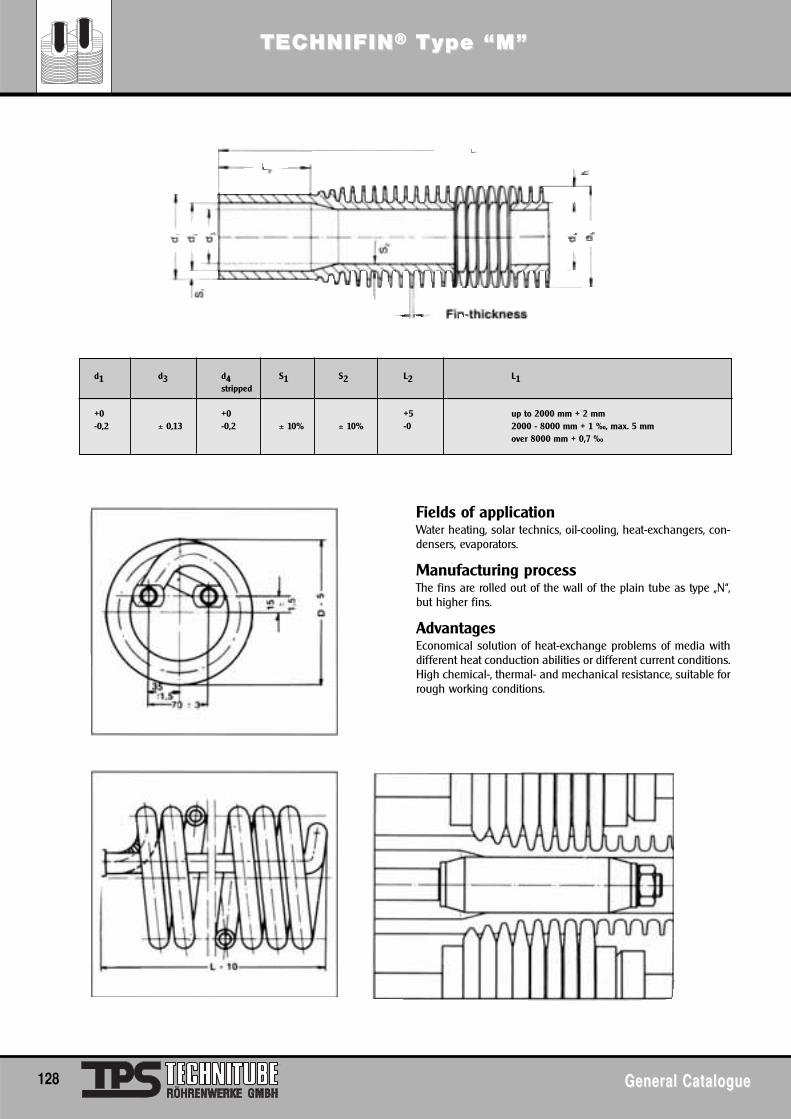
128 General CatalogueGeneral Catalogue
d1 d3 d4 S1 S2 L2 L1stripped
+0 +0 +5 up to 2000 mm + 2 mm-0,2 ± 0,13 -0,2 ± 10% ± 10% -0 2000 - 8000 mm + 1 ‰, max. 5 mm
over 8000 mm + 0,7 ‰
Fields of applicationWater heating, solar technics, oil-cooling, heat-exchangers, con-densers, evaporators.
Manufacturing processThe fins are rolled out of the wall of the plain tube as type „N“,but higher fins.
AdvantagesEconomical solution of heat-exchange problems of media withdifferent heat conduction abilities or different current conditions.High chemical-, thermal- and mechanical resistance, suitable forrough working conditions.
TECTECHNIFINHNIFIN®® TType “M”ype “M”
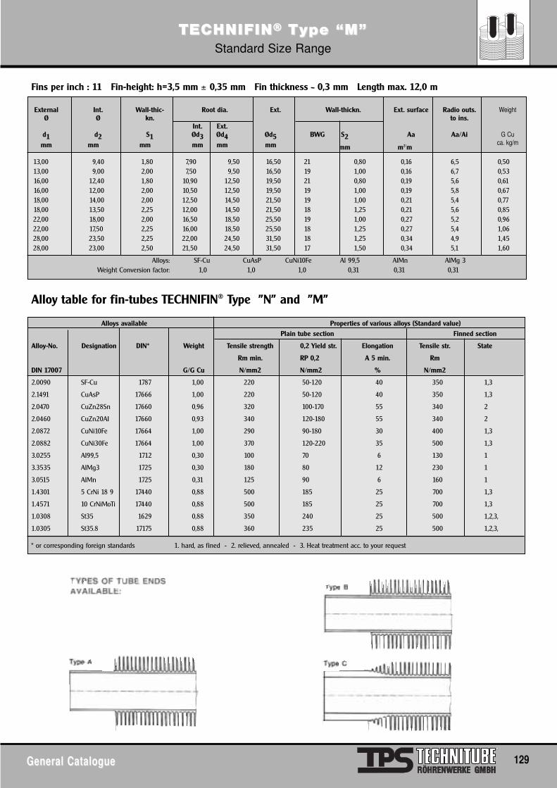
General CatalogueGeneral Catalogue 129
TECTECHNIFINHNIFIN®® TType “M”ype “M”Standard Size Range
Int.Ø
d2mm
Ext. surface
Aa
m2/m
Radio outs.to ins.
Aa/Ai
Weight
G Cuca. kg/m
Wall-thic-kn.
S1mm
Ext.
Ød5mm
ExternalØ
d1mm
Root dia.
Int. Ext.Ød3 Ød4mm mm
Wall-thickn.
BWG S2
mm
13,00 9,40 1,80 7,90 9,50 16,50 21 0,80 0,16 6,5 0,5013,00 9,00 2,00 7,50 9,50 16,50 19 1,00 0,16 6,7 0,5316,00 12,40 1,80 10,90 12,50 19,50 21 0,80 0,19 5,6 0,6116,00 12,00 2,00 10,50 12,50 19,50 19 1,00 0,19 5,8 0,6718,00 14,00 2,00 12,50 14,50 21,50 19 1,00 0,21 5,4 0,7718,00 13,50 2,25 12,00 14,50 21,50 18 1,25 0,21 5,6 0,8522,00 18,00 2,00 16,50 18,50 25,50 19 1,00 0,27 5,2 0,9622,00 17,50 2,25 16,00 18,50 25,50 18 1,25 0,27 5,4 1,0628,00 23,50 2,25 22,00 24,50 31,50 18 1,25 0,34 4,9 1,4528,00 23,00 2,50 21,50 24,50 31,50 17 1,50 0,34 5,1 1,60
Alloys: SF-Cu CuAsP CuNi10Fe Al 99,5 AlMn AlMg 3Weight Conversion factor: 1,0 1,0 1,0 0,31 0,31 0,31
Alloys available Properties of various alloys (Standard value)Plain tube section Finned section
Alloy-No. Designation DIN* Weight Tensile strength 0,2 Yield str. Elongation Tensile str. State
Rm min. RP 0,2 A 5 min. Rm
DIN 17007 G/G Cu N/mm2 N/mm2 % N/mm2
2.0090 SF-Cu 1787 1,00 220 50-120 40 350 1,3
2.1491 CuAsP 17666 1,00 220 50-120 40 350 1,3
2.0470 CuZn28Sn 17660 0,96 320 100-170 55 340 2
2.0460 CuZn20AI 17660 0,93 340 120-180 55 340 2
2.0872 CuNi10Fe 17664 1,00 290 90-180 30 400 1,3
2.0882 CuNi30Fe 17664 1,00 370 120-220 35 500 1,3
3.0255 AI99,5 1712 0,30 100 70 6 130 1
3.3535 AIMg3 1725 0,30 180 80 12 230 1
3.0515 AIMn 1725 0,31 125 90 6 160 1
1.4301 5 CrNi 18 9 17440 0,88 500 185 25 700 1,3
1.4571 10 CrNiMoTi 17440 0,88 500 185 25 700 1,3
1.0308 St35 1629 0,88 350 240 25 500 1,2,3,
1.0305 St35.8 17175 0,88 360 235 25 500 1,2,3,
Fins per inch : 11 Fin-height: h=3,5 mm ± 0,35 mm Fin thickness ~ 0,3 mm Length max. 12,0 m
Alloy table for fin-tubes TECHNIFIN® Type "N" and "M"
* or corresponding foreign standards 1. hard, as fined - 2. relieved, annealed - 3. Heat treatment acc. to your request
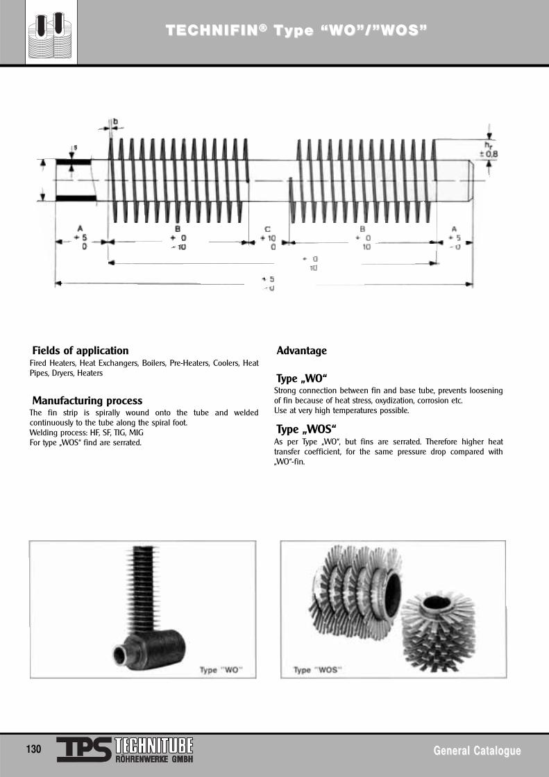
TECTECHNIFINHNIFIN®® TType “Wype “WO”/”WO”/”WOS”OS”
130 General CatalogueGeneral Catalogue
Fields of applicationFired Heaters, Heat Exchangers, Boilers, Pre-Heaters, Coolers, HeatPipes, Dryers, Heaters
Manufacturing processThe fin strip is spirally wound onto the tube and weldedcontinuously to the tube along the spiral foot.Welding process: HF, SF, TIG, MIGFor type „WOS“ find are serrated.
Advantage
Type „WO“Strong connection between fin and base tube, prevents looseningof fin because of heat stress, oxydization, corrosion etc.Use at very high temperatures possible.
Type „WOS“As per Type „WO“, but fins are serrated. Therefore higher heattransfer coefficient, for the same pressure drop compared with„WO“-fin.
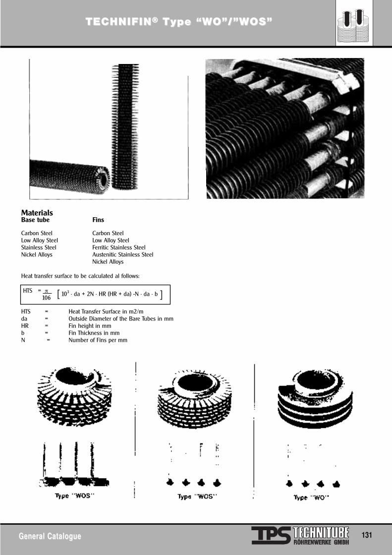
TECTECHNIFINHNIFIN®® TType “Wype “WO”/”WO”/”WOS”OS”
General CatalogueGeneral Catalogue 131
MaterialsBase tube Fins
Carbon Steel Carbon SteelLow Alloy Steel Low Alloy SteelStainless Steel Ferritic Stainless SteelNickel Alloys Austenitic Stainless Steel
Nickel Alloys
Heat transfer surface to be calculated al follows:
HTS = Heat Transfer Surface in m2/mda = Outside Diameter of the Bare Tubes in mmHR = Fin height in mmb = Fin Thickness in mmN = Number of Fins per mm
]HTS = π 103 · da + 2N · HR (HR + da) -N · da · b106 [
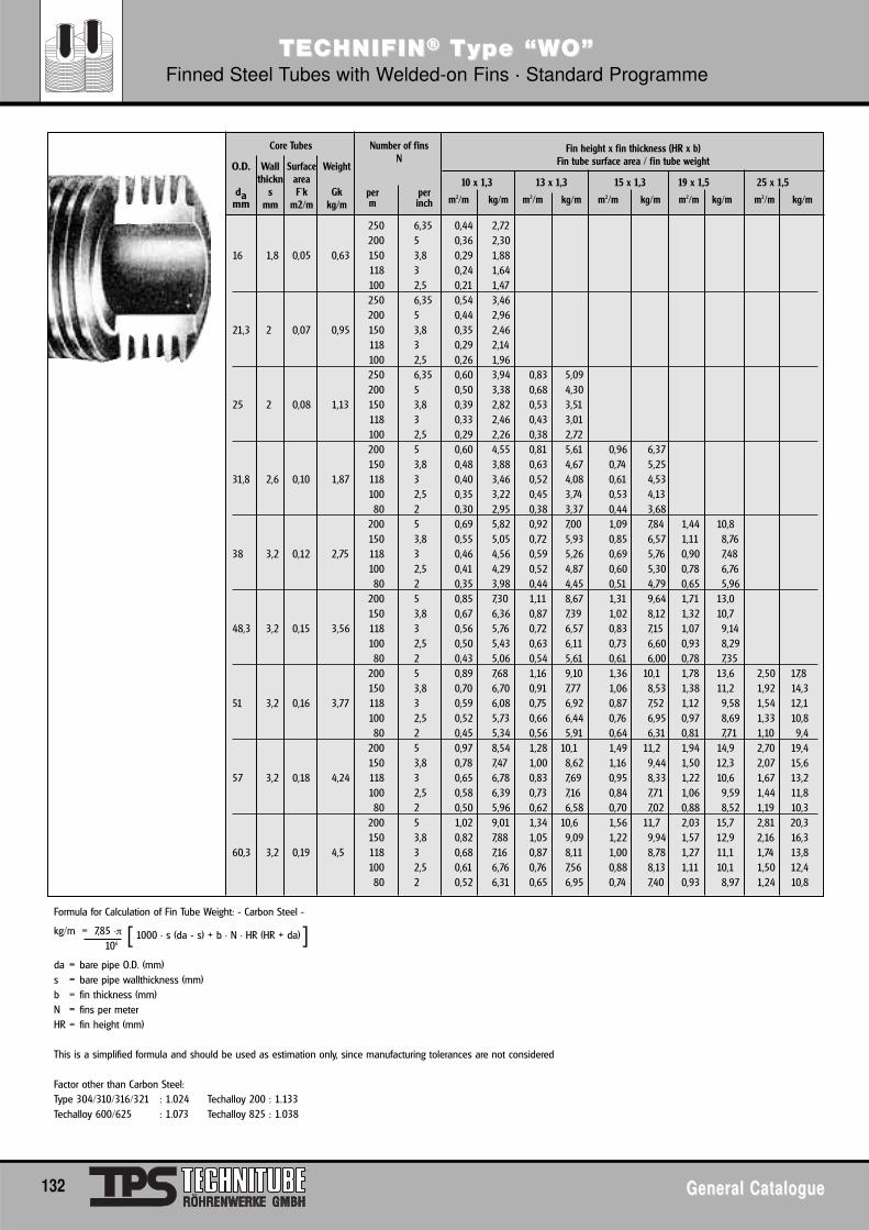
132 General CatalogueGeneral Catalogue
250 6,35 0,44 2,72200 5 0,36 2,30
16 1,8 0,05 0,63 150 3,8 0,29 1,88118 3 0,24 1,64100 2,5 0,21 1,47250 6,35 0,54 3,46200 5 0,44 2,96
21,3 2 0,07 0,95 150 3,8 0,35 2,46118 3 0,29 2,14100 2,5 0,26 1,96250 6,35 0,60 3,94 0,83 5,09200 5 0,50 3,38 0,68 4,30
25 2 0,08 1,13 150 3,8 0,39 2,82 0,53 3,51118 3 0,33 2,46 0,43 3,01100 2,5 0,29 2,26 0,38 2,72200 5 0,60 4,55 0,81 5,61 0,96 6,37150 3,8 0,48 3,88 0,63 4,67 0,74 5,25
31,8 2,6 0,10 1,87 118 3 0,40 3,46 0,52 4,08 0,61 4,53100 2,5 0,35 3,22 0,45 3,74 0,53 4,1380 2 0,30 2,95 0,38 3,37 0,44 3,68
200 5 0,69 5,82 0,92 7,00 1,09 7,84 1,44 10,8150 3,8 0,55 5,05 0,72 5,93 0,85 6,57 1,11 8,76
38 3,2 0,12 2,75 118 3 0,46 4,56 0,59 5,26 0,69 5,76 0,90 7,48100 2,5 0,41 4,29 0,52 4,87 0,60 5,30 0,78 6,7680 2 0,35 3,98 0,44 4,45 0,51 4,79 0,65 5,96
200 5 0,85 7,30 1,11 8,67 1,31 9,64 1,71 13,0150 3,8 0,67 6,36 0,87 7,39 1,02 8,12 1,32 10,7
48,3 3,2 0,15 3,56 118 3 0,56 5,76 0,72 6,57 0,83 7,15 1,07 9,14100 2,5 0,50 5,43 0,63 6,11 0,73 6,60 0,93 8,2980 2 0,43 5,06 0,54 5,61 0,61 6,00 0,78 7,35
200 5 0,89 7,68 1,16 9,10 1,36 10,1 1,78 13,6 2,50 17,8150 3,8 0,70 6,70 0,91 7,77 1,06 8,53 1,38 11,2 1,92 14,3
51 3,2 0,16 3,77 118 3 0,59 6,08 0,75 6,92 0,87 7,52 1,12 9,58 1,54 12,1100 2,5 0,52 5,73 0,66 6,44 0,76 6,95 0,97 8,69 1,33 10,880 2 0,45 5,34 0,56 5,91 0,64 6,31 0,81 7,71 1,10 9,4
200 5 0,97 8,54 1,28 10,1 1,49 11,2 1,94 14,9 2,70 19,4150 3,8 0,78 7,47 1,00 8,62 1,16 9,44 1,50 12,3 2,07 15,6
57 3,2 0,18 4,24 118 3 0,65 6,78 0,83 7,69 0,95 8,33 1,22 10,6 1,67 13,2100 2,5 0,58 6,39 0,73 7,16 0,84 7,71 1,06 9,59 1,44 11,880 2 0,50 5,96 0,62 6,58 0,70 7,02 0,88 8,52 1,19 10,3
200 5 1,02 9,01 1,34 10,6 1,56 11,7 2,03 15,7 2,81 20,3150 3,8 0,82 7,88 1,05 9,09 1,22 9,94 1,57 12,9 2,16 16,3
60,3 3,2 0,19 4,5 118 3 0,68 7,16 0,87 8,11 1,00 8,78 1,27 11,1 1,74 13,8100 2,5 0,61 6,76 0,76 7,56 0,88 8,13 1,11 10,1 1,50 12,480 2 0,52 6,31 0,65 6,95 0,74 7,40 0,93 8,97 1,24 10,8
Formula for Calculation of Fin Tube Weight: - Carbon Steel -
kg/m = 7,85 ·π 1000 · s (da - s) + b · N · HR (HR + da)106
da = bare pipe O.D. (mm)s = bare pipe wallthickness (mm)b = fin thickness (mm)N = fins per meterHR = fin height (mm)
This is a simplified formula and should be used as estimation only, since manufacturing tolerances are not considered
Factor other than Carbon Steel:Type 304/310/316/321 : 1.024 Techalloy 200 : 1.133Techalloy 600/625 : 1.073 Techalloy 825 : 1.038
O.D.
damm
Wallthickn
smm
SurfaceareaF´k
m2/m
Weight
Gkkg/m
Core Tubes Number of finsN
per perm inch
Fin height x fin thickness (HR x b)Fin tube surface area / fin tube weight
10 x 1,3 13 x 1,3 15 x 1,3 19 x 1,5 25 x 1,5
m2/m kg/m m2/m kg/m m2/m kg/m m2/m kg/m m2/m kg/m
[ ]
TECTECHNIFINHNIFIN®® TType “Wype “WO”O”Finned Steel Tubes with Welded-on Fins · Standard Programme
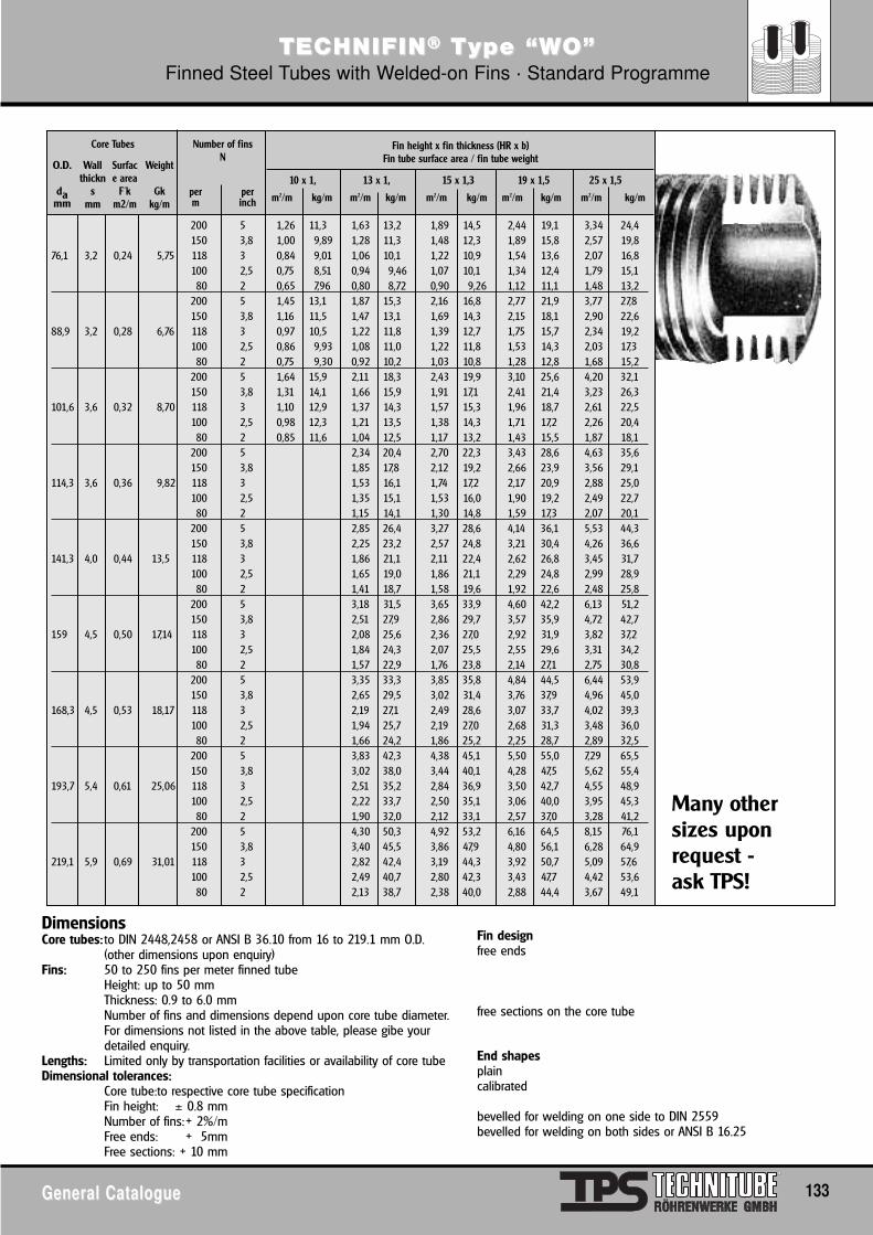
General CatalogueGeneral Catalogue 133
TECTECHNIFINHNIFIN®® TType “Wype “WO”O”Finned Steel Tubes with Welded-on Fins · Standard Programme
DimensionsCore tubes: to DIN 2448,2458 or ANSI B 36.10 from 16 to 219.1 mm O.D.
(other dimensions upon enquiry)Fins: 50 to 250 fins per meter finned tube
Height: up to 50 mmThickness: 0.9 to 6.0 mmNumber of fins and dimensions depend upon core tube diameter.For dimensions not listed in the above table, please gibe yourdetailed enquiry.
Lengths: Limited only by transportation facilities or availability of core tubeDimensional tolerances:
Core tube:to respective core tube specificationFin height: ± 0.8 mmNumber of fins:+ 2%/mFree ends: + 5mmFree sections: + 10 mm
Fin designfree ends
free sections on the core tube
End shapesplaincalibrated
bevelled for welding on one side to DIN 2559bevelled for welding on both sides or ANSI B 16.25
200 5 1,26 11,3 1,63 13,2 1,89 14,5 2,44 19,1 3,34 24,4150 3,8 1,00 9,89 1,28 11,3 1,48 12,3 1,89 15,8 2,57 19,8
76,1 3,2 0,24 5,75 118 3 0,84 9,01 1,06 10,1 1,22 10,9 1,54 13,6 2,07 16,8100 2,5 0,75 8,51 0,94 9,46 1,07 10,1 1,34 12,4 1,79 15,180 2 0,65 7,96 0,80 8,72 0,90 9,26 1,12 11,1 1,48 13,2
200 5 1,45 13,1 1,87 15,3 2,16 16,8 2,77 21,9 3,77 27,8150 3,8 1,16 11,5 1,47 13,1 1,69 14,3 2,15 18,1 2,90 22,6
88,9 3,2 0,28 6,76 118 3 0,97 10,5 1,22 11,8 1,39 12,7 1,75 15,7 2,34 19,2100 2,5 0,86 9,93 1,08 11,0 1,22 11,8 1,53 14,3 2,03 17,380 2 0,75 9,30 0,92 10,2 1,03 10,8 1,28 12,8 1,68 15,2
200 5 1,64 15,9 2,11 18,3 2,43 19,9 3,10 25,6 4,20 32,1150 3,8 1,31 14,1 1,66 15,9 1,91 17,1 2,41 21,4 3,23 26,3
101,6 3,6 0,32 8,70 118 3 1,10 12,9 1,37 14,3 1,57 15,3 1,96 18,7 2,61 22,5100 2,5 0,98 12,3 1,21 13,5 1,38 14,3 1,71 17,2 2,26 20,480 2 0,85 11,6 1,04 12,5 1,17 13,2 1,43 15,5 1,87 18,1
200 5 2,34 20,4 2,70 22,3 3,43 28,6 4,63 35,6150 3,8 1,85 17,8 2,12 19,2 2,66 23,9 3,56 29,1
114,3 3,6 0,36 9,82 118 3 1,53 16,1 1,74 17,2 2,17 20,9 2,88 25,0100 2,5 1,35 15,1 1,53 16,0 1,90 19,2 2,49 22,780 2 1,15 14,1 1,30 14,8 1,59 17,3 2,07 20,1
200 5 2,85 26,4 3,27 28,6 4,14 36,1 5,53 44,3150 3,8 2,25 23,2 2,57 24,8 3,21 30,4 4,26 36,6
141,3 4,0 0,44 13,5 118 3 1,86 21,1 2,11 22,4 2,62 26,8 3,45 31,7100 2,5 1,65 19,0 1,86 21,1 2,29 24,8 2,99 28,980 2 1,41 18,7 1,58 19,6 1,92 22,6 2,48 25,8
200 5 3,18 31,5 3,65 33,9 4,60 42,2 6,13 51,2150 3,8 2,51 27,9 2,86 29,7 3,57 35,9 4,72 42,7
159 4,5 0,50 17,14 118 3 2,08 25,6 2,36 27,0 2,92 31,9 3,82 37,2100 2,5 1,84 24,3 2,07 25,5 2,55 29,6 3,31 34,280 2 1,57 22,9 1,76 23,8 2,14 27,1 2,75 30,8
200 5 3,35 33,3 3,85 35,8 4,84 44,5 6,44 53,9150 3,8 2,65 29,5 3,02 31,4 3,76 37,9 4,96 45,0
168,3 4,5 0,53 18,17 118 3 2,19 27,1 2,49 28,6 3,07 33,7 4,02 39,3100 2,5 1,94 25,7 2,19 27,0 2,68 31,3 3,48 36,080 2 1,66 24,2 1,86 25,2 2,25 28,7 2,89 32,5
200 5 3,83 42,3 4,38 45,1 5,50 55,0 7,29 65,5150 3,8 3,02 38,0 3,44 40,1 4,28 47,5 5,62 55,4
193,7 5,4 0,61 25,06 118 3 2,51 35,2 2,84 36,9 3,50 42,7 4,55 48,9100 2,5 2,22 33,7 2,50 35,1 3,06 40,0 3,95 45,380 2 1,90 32,0 2,12 33,1 2,57 37,0 3,28 41,2
200 5 4,30 50,3 4,92 53,2 6,16 64,5 8,15 76,1150 3,8 3,40 45,5 3,86 47,9 4,80 56,1 6,28 64,9
219,1 5,9 0,69 31,01 118 3 2,82 42,4 3,19 44,3 3,92 50,7 5,09 57,6100 2,5 2,49 40,7 2,80 42,3 3,43 47,7 4,42 53,680 2 2,13 38,7 2,38 40,0 2,88 44,4 3,67 49,1
O.D.
damm
Wallthickn
smm
Surface area
F´km2/m
Weight
Gkkg/m
Core Tubes Number of finsN
per perm inch
Fin height x fin thickness (HR x b)Fin tube surface area / fin tube weight
10 x 1, 13 x 1, 15 x 1,3 19 x 1,5 25 x 1,5
m2/m kg/m m2/m kg/m m2/m kg/m m2/m kg/m m2/m kg/m
Many othersizes uponrequest - ask TPS!
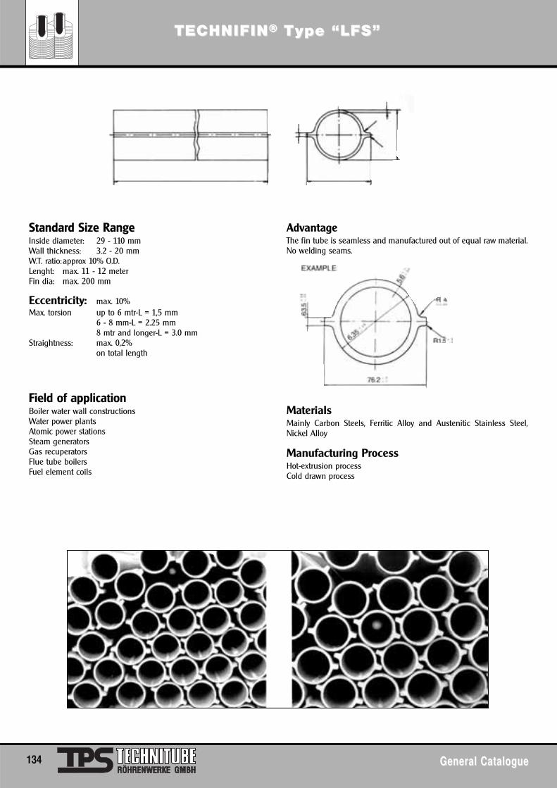
134 General CatalogueGeneral Catalogue
TECTECHNIFINHNIFIN®® TType “LFS”ype “LFS”
Standard Size RangeInside diameter: 29 - 110 mmWall thickness: 3.2 - 20 mmW.T. ratio:approx 10% O.D.Lenght: max. 11 - 12 meterFin dia: max. 200 mm
Eccentricity: max. 10%Max. torsion up to 6 mtr-L = 1,5 mm
6 - 8 mm-L = 2.25 mm8 mtr and longer-L = 3.0 mm
Straightness: max. 0,2%on total length
Field of applicationBoiler water wall constructionsWater power plantsAtomic power stationsSteam generatorsGas recuperatorsFlue tube boilersFuel element coils
AdvantageThe fin tube is seamless and manufactured out of equal raw material.No welding seams.
MaterialsMainly Carbon Steels, Ferritic Alloy and Austenitic Stainless Steel,Nickel Alloy
Manufacturing ProcessHot-extrusion processCold drawn process
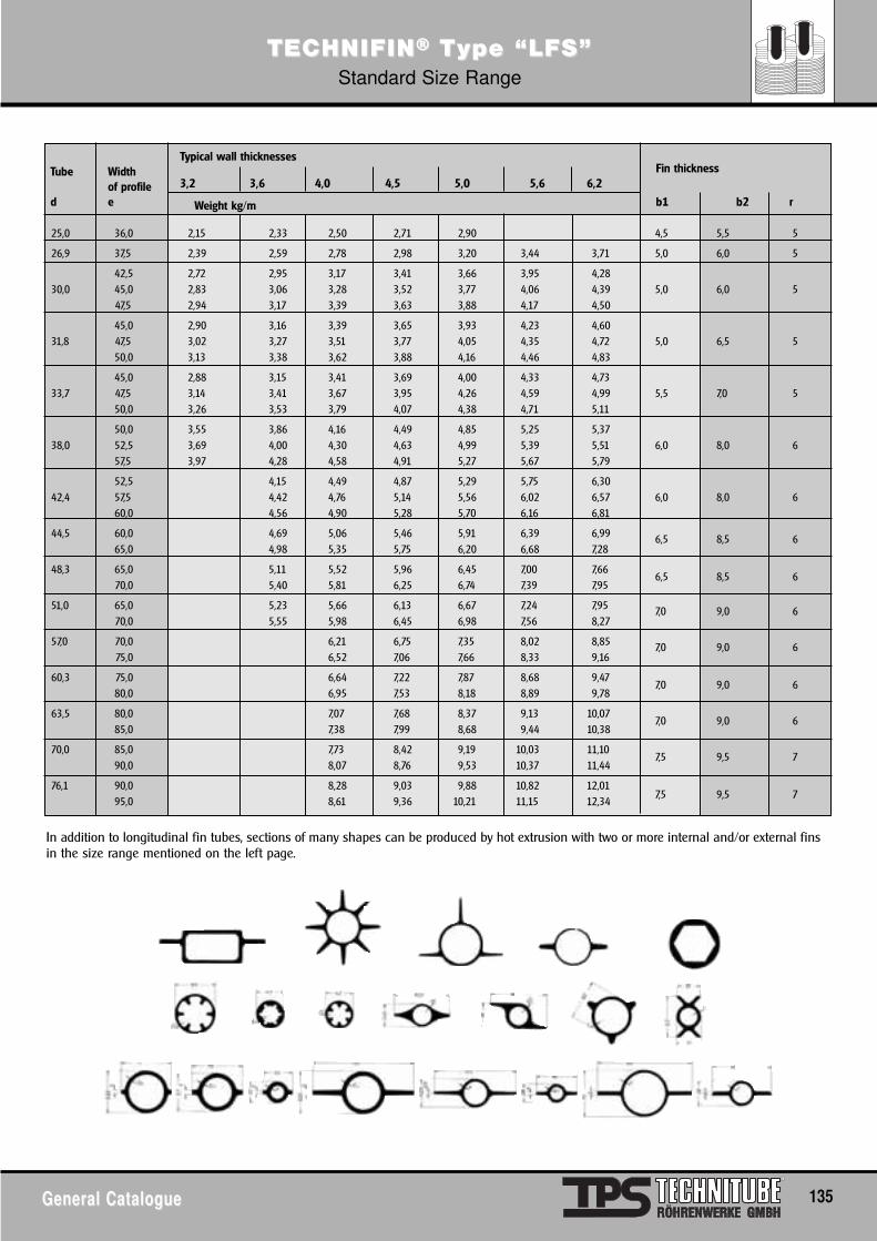
General CatalogueGeneral Catalogue 135
TECTECHNIFINHNIFIN®® TType “LFS”ype “LFS”Standard Size Range
Typical wall thicknessesFin thicknessTube Width
3,2 3,6 4,0 4,5 5,0 5,6 6,2of profile
Weight kg/md e b1 b2 r
25,0 36,0 2,15 2,33 2,50 2,71 2,90 4,5 5,5 5
26,9 37,5 2,39 2,59 2,78 2,98 3,20 3,44 3,71 5,0 6,0 5
42,5 2,72 2,95 3,17 3,41 3,66 3,95 4,2830,0 45,0 2,83 3,06 3,28 3,52 3,77 4,06 4,39 5,0 6,0 5
47,5 2,94 3,17 3,39 3,63 3,88 4,17 4,50
45,0 2,90 3,16 3,39 3,65 3,93 4,23 4,6031,8 47,5 3,02 3,27 3,51 3,77 4,05 4,35 4,72 5,0 6,5 5
50,0 3,13 3,38 3,62 3,88 4,16 4,46 4,83
45,0 2,88 3,15 3,41 3,69 4,00 4,33 4,7333,7 47,5 3,14 3,41 3,67 3,95 4,26 4,59 4,99 5,5 7,0 5
50,0 3,26 3,53 3,79 4,07 4,38 4,71 5,11
50,0 3,55 3,86 4,16 4,49 4,85 5,25 5,3738,0 52,5 3,69 4,00 4,30 4,63 4,99 5,39 5,51 6,0 8,0 6
57,5 3,97 4,28 4,58 4,91 5,27 5,67 5,79
52,5 4,15 4,49 4,87 5,29 5,75 6,3042,4 57,5 4,42 4,76 5,14 5,56 6,02 6,57 6,0 8,0 6
60,0 4,56 4,90 5,28 5,70 6,16 6,81
44,5 60,0 4,69 5,06 5,46 5,91 6,39 6,99 6,5 8,5 665,0 4,98 5,35 5,75 6,20 6,68 7,28
48,3 65,0 5,11 5,52 5,96 6,45 7,00 7,666,5 8,5 6
70,0 5,40 5,81 6,25 6,74 7,39 7,95
51,0 65,0 5,23 5,66 6,13 6,67 7,24 7,95 7,0 9,0 670,0 5,55 5,98 6,45 6,98 7,56 8,27
57,0 70,0 6,21 6,75 7,35 8,02 8,85 7,0 9,0 675,0 6,52 7,06 7,66 8,33 9,16
60,3 75,0 6,64 7,22 7,87 8,68 9,477,0 9,0 6
80,0 6,95 7,53 8,18 8,89 9,78
63,5 80,0 7,07 7,68 8,37 9,13 10,077,0 9,0 6
85,0 7,38 7,99 8,68 9,44 10,38
70,0 85,0 7,73 8,42 9,19 10,03 11,107,5 9,5 7
90,0 8,07 8,76 9,53 10,37 11,44
76,1 90,0 8,28 9,03 9,88 10,82 12,017,5 9,5 7
95,0 8,61 9,36 10,21 11,15 12,34
In addition to longitudinal fin tubes, sections of many shapes can be produced by hot extrusion with two or more internal and/or external finsin the size range mentioned on the left page.
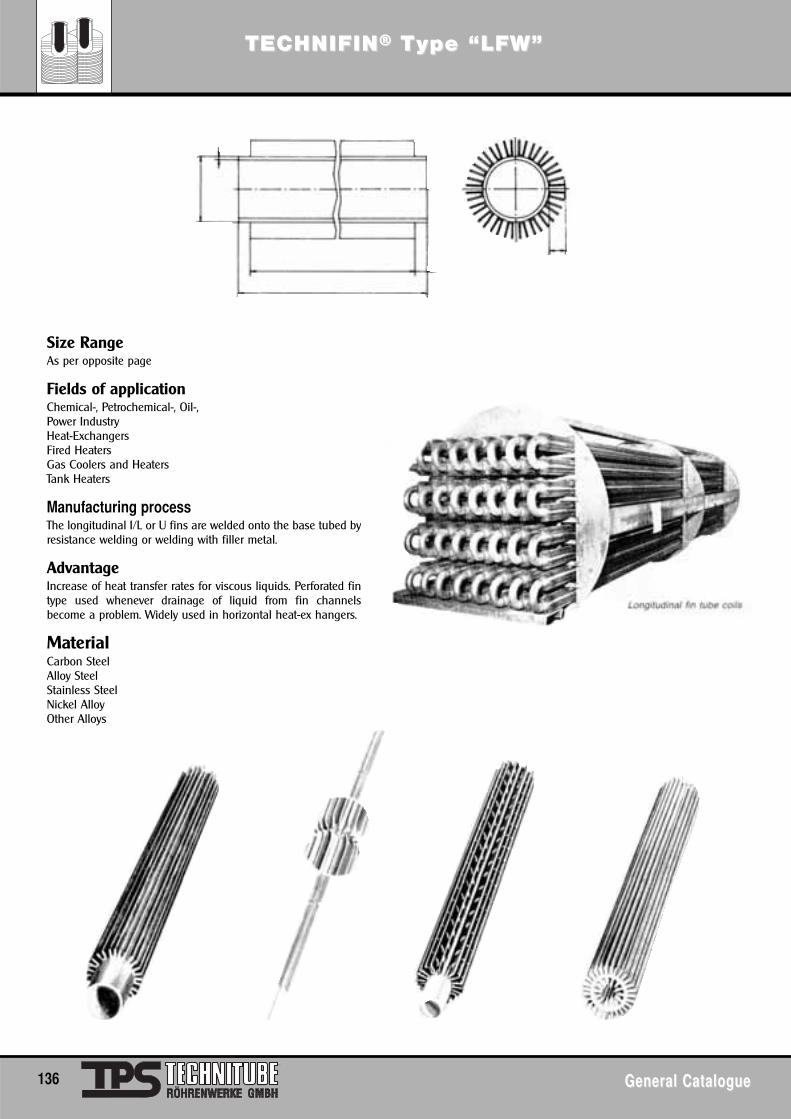
136 General CatalogueGeneral Catalogue
TECTECHNIFINHNIFIN®® TType “LFW”ype “LFW”
Size RangeAs per opposite page
Fields of applicationChemical-, Petrochemical-, Oil-, Power IndustryHeat-ExchangersFired HeatersGas Coolers and HeatersTank Heaters
Manufacturing processThe longitudinal I/L or U fins are welded onto the base tubed byresistance welding or welding with filler metal.
AdvantageIncrease of heat transfer rates for viscous liquids. Perforated fintype used whenever drainage of liquid from fin channelsbecome a problem. Widely used in horizontal heat-ex hangers.
MaterialCarbon SteelAlloy SteelStainless SteelNickel Alloy Other Alloys
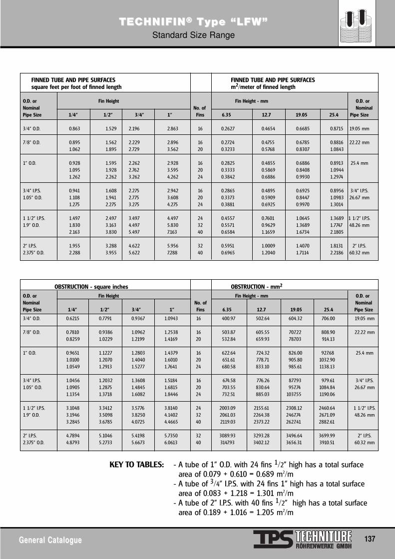
General CatalogueGeneral Catalogue 137
TECTECHNIFINHNIFIN®® TType “LFW”ype “LFW”Standard Size Range
KEY TO TABLES: - A tube of 1” O.D. with 24 fins 1/2” high has a total surface area of 0.079 + 0.610 = 0.689 m2/m
- A tube of 3/4” I.P.S. with 24 fins 1” high has a total surface area of 0.083 + 1.218 = 1.301 m2/m
- A tube of 2” I.P.S. with 40 fins 1/2” high has a total surface area of 0.189 + 1.016 = 1.205 m2/m
FINNED TUBE AND PIPE SURFACES FINNED TUBE AND PIPE SURFACESsquare feet per foot of finned length m2/meter of finned length
O.D. or Fin Height Fin Height - mm O.D. orNominal No. of NominalPipe Size 1/4" 1/2" 3/4" 1" Fins 6.35 12.7 19.05 25.4 Pipe Size
3/4" O.D. 0.863 1.529 2.196 2.863 16 0.2627 0.4654 0.6685 0.8715 19.05 mm
7/8" O.D. 0.895 1.562 2.229 2.896 16 0.2724 0.4755 0.6785 0.8816 22.22 mm1.062 1.895 2.729 3.562 20 0.3233 0.5768 0.8307 1.0843
1" O.D. 0.928 1.595 2.262 2.928 16 0.2825 0.4855 0.6886 0.8913 25.4 mm1.095 1.928 2.762 3.595 20 0.3333 0.5869 0.8408 1.09441.262 2.262 3.262 4.262 24 0.3842 0.6886 0.9930 1.2974
3/4" I.P.S. 0.941 1.608 2.275 2.942 16 0.2865 0.4895 0.6925 0.8956 3/4" I.P.S.1.05" O.D. 1.108 1.941 2.775 3.608 20 0.3373 0.5909 0.8447 1.0983 26.67 mm
1.275 2.275 3.275 4.275 24 0.3881 0.6925 0.9970 1.3014
1 1/2" I.P.S. 1.497 2.497 3.497 4.497 24 0.4557 0.7601 1.0645 1.3689 1 1/2" I.P.S.1.9" O.D. 1.830 3.163 4.497 5.830 32 0.5571 0.9629 1.3689 1.7747 48.26 mm
2.163 3.830 5.497 7.163 40 0.6584 1.1659 1.6734 2.1805
2" I.P.S. 1.955 3.288 4.622 5.956 32 0.5951 1.0009 1.4070 1.8131 2" I.P.S.2.375" O.D. 2.288 3.955 5.622 7.288 40 0.6965 1.2040 1.7114 2.2186 60.32 mm
OBSTRUCTION - square inches OBSTRUCTION - mm2
O.D. or Fin Height Fin Height - mm O.D. orNominal No. of NominalPipe Size 1/4" 1/2" 3/4" 1" Fins 6.35 12.7 19.05 25.4 Pipe Size
3/4" O.D. 0.6215 0.7791 0.9367 1.0943 16 400.97 502.64 604.32 706.00 19.05 mm
7/8" O.D. 0.7810 0.9386 1.0962 1.2538 16 503.87 605.55 707.22 808.90 22.22 mm0.8259 1.0229 1.2199 1.4169 20 532.84 659.93 787.03 914.13
1" O.D. 0.9651 1.1227 1.2803 1.4379 16 622.64 724.32 826.00 927.68 25.4 mm1.0100 1.2070 1.4040 1.6010 20 651.61 778.71 905.80 1032.901.0549 1.2913 1.5277 1.7641 24 680.58 833.10 985.61 1138.13
3/4" I.P.S. 1.0456 1.2032 1.3608 1.5184 16 674.58 776.26 877.93 979.61 3/4" I.P.S.1.05" O.D. 1.0905 1.2875 1.4845 1.6815 20 703.55 830.64 957.74 1084.84 26.67 mm
1.1354 1.3718 1.6082 1.8446 24 732.51 885.03 1037.55 1190.06
1 1/2" I.P.S. 3.1048 3.3412 3.5776 3.8140 24 2003.09 2155.61 2308.12 2460.64 1 1/2" I.P.S.1.9" O.D. 3.1946 3.5098 3.8250 4.1402 32 2061.03 2264.38 2467.74 2671.09 48.26 mm
3.2845 3.6785 4.0725 4.4665 40 2119.03 2373.22 2627.41 2882.61
2" I.P.S. 4.7894 5.1046 5.4198 5.7350 32 3089.93 3293.28 3496.64 3699.99 2" I.P.S.2.375" O.D. 4.8793 5.2733 5.6673 6.0613 40 3147.93 3402.12 3656.31 3910.51 60.32 mm
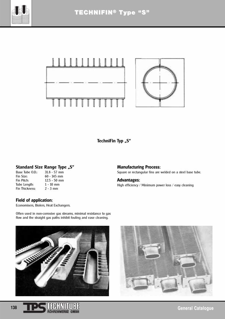
138 General CatalogueGeneral Catalogue
TECTECHNIFINHNIFIN®® TType “S”ype “S”
Standard Size Range Type „S“Base Tube O.D.: 31.8 - 57 mmFin Size: 60 - 145 mmFin Pitch: 12.5 - 50 mmTube Length: 1 - 10 mmFin Thickness: 2 - 3 mm
Field of application:Economisers, Biolers, Heat Exchangers.
Often used in non-corrosive gas streams, minimal resistance to gasflow and the straight gas paths inhibit fouling and ease cleaning.
Manufacturing Process:Square or rectangular fins are welded on a steel base tube.
Advantages:High efficiency / Minimum power loss / easy cleaning
TechniFin Typ „S“
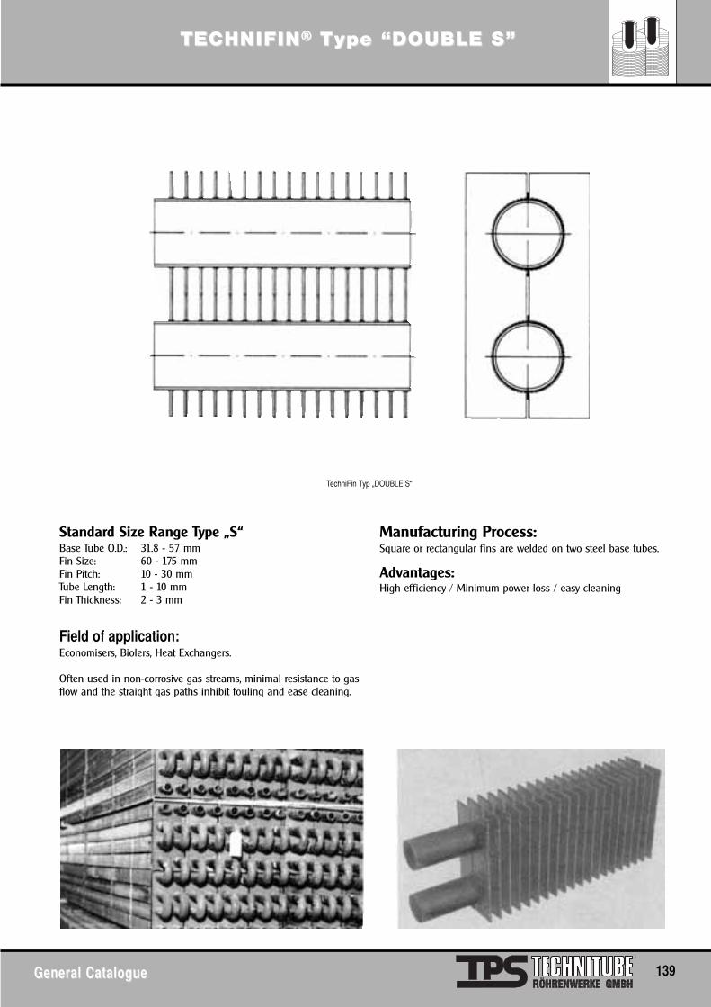
General CatalogueGeneral Catalogue 139
TECTECHNIFINHNIFIN®® TType “DOUBLE S”ype “DOUBLE S”
Standard Size Range Type „S“Base Tube O.D.: 31.8 - 57 mmFin Size: 60 - 175 mmFin Pitch: 10 - 30 mmTube Length: 1 - 10 mmFin Thickness: 2 - 3 mm
Field of application:Economisers, Biolers, Heat Exchangers.
Often used in non-corrosive gas streams, minimal resistance to gasflow and the straight gas paths inhibit fouling and ease cleaning.
Manufacturing Process:Square or rectangular fins are welded on two steel base tubes.
Advantages:High efficiency / Minimum power loss / easy cleaning
TechniFin Typ „DOUBLE S“
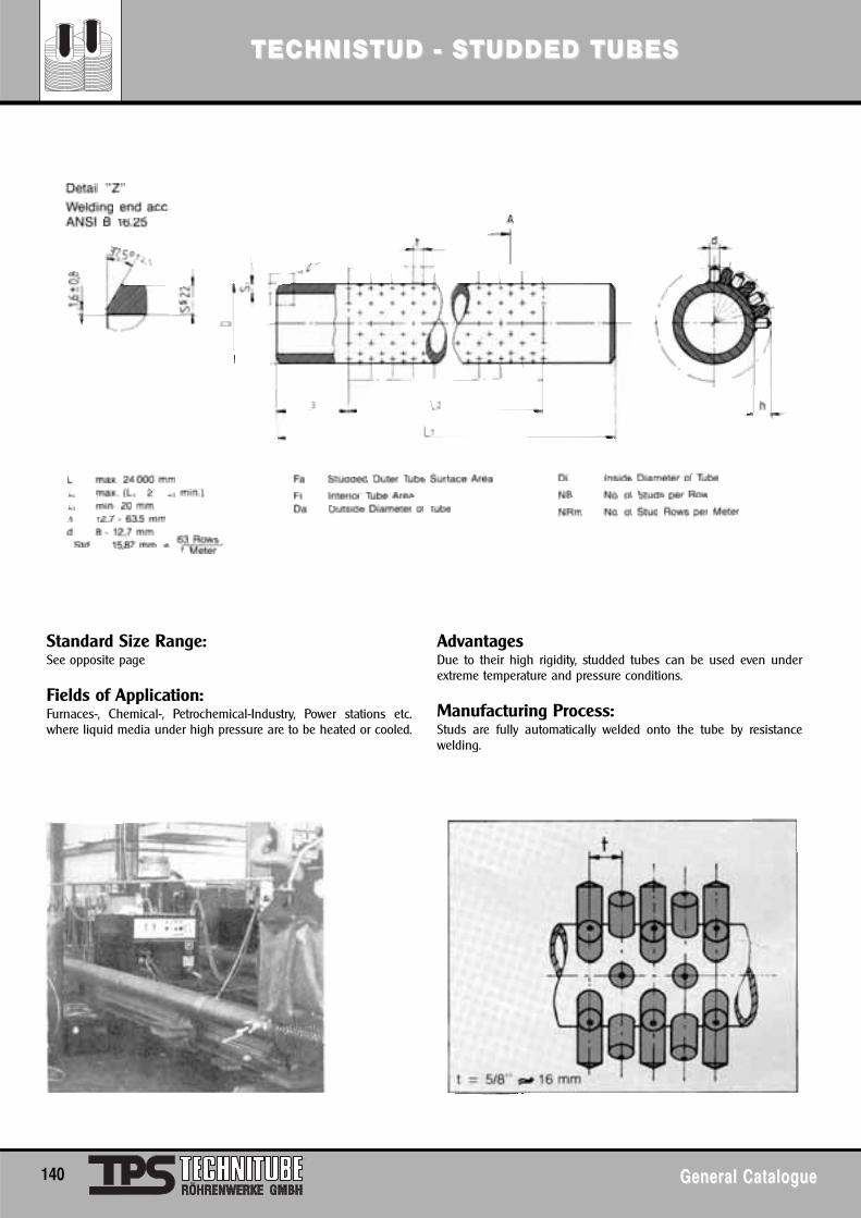
TECTECHNISHNISTUD - STUD - STUDDED TUBESTUDDED TUBES
140 General CatalogueGeneral Catalogue
Standard Size Range:See opposite page
Fields of Application:Furnaces-, Chemical-, Petrochemical-Industry, Power stations etc.where liquid media under high pressure are to be heated or cooled.
AdvantagesDue to their high rigidity, studded tubes can be used even underextreme temperature and pressure conditions.
Manufacturing Process:Studs are fully automatically welded onto the tube by resistancewelding.
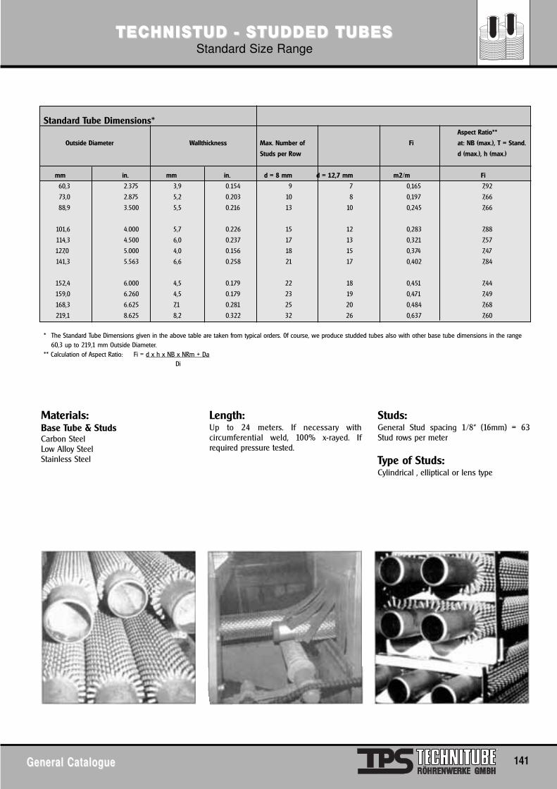
TECTECHNISHNISTUD - STUD - STUDDED TUBESTUDDED TUBESStandard Size Range
General CatalogueGeneral Catalogue 141
Materials:Base Tube & StudsCarbon SteelLow Alloy SteelStainless Steel
Length:Up to 24 meters. If necessary withcircumferential weld, 100% x-rayed. Ifrequired pressure tested.
Studs:General Stud spacing 1/8“ (16mm) = 63Stud rows per meter
Type of Studs:Cylindrical , elliptical or lens type
Standard Tube Dimensions*Aspect Ratio**
Outside Diameter Wallthickness Max. Number of Fi at: NB (max.), T = Stand.
Studs per Row d (max.), h (max.)
mm in. mm in. d = 8 mm d = 12,7 mm m2/m Fi
60,3 2.375 3,9 0.154 9 7 0,165 7,92
73,0 2.875 5,2 0.203 10 8 0,197 7,66
88,9 3.500 5,5 0.216 13 10 0,245 7,66
101,6 4.000 5,7 0.226 15 12 0,283 7,88
114,3 4.500 6,0 0.237 17 13 0,321 7,57
127,0 5.000 4,0 0.156 18 15 0,374 7,47
141,3 5.563 6,6 0.258 21 17 0,402 7,84
152,4 6.000 4,5 0.179 22 18 0,451 7,44
159,0 6.260 4,5 0.179 23 19 0,471 7,49
168,3 6.625 7,1 0.281 25 20 0,484 7,68
219,1 8.625 8,2 0.322 32 26 0,637 7,60
* The Standard Tube Dimensions given in the above table are taken from typical orders. 0f course, we produce studded tubes also with other base tube dimensions in the range60,3 up to 219,1 mm Outside Diameter.
** Calculation of Aspect Ratio: Fi = d x h x NB x NRm + DaDi
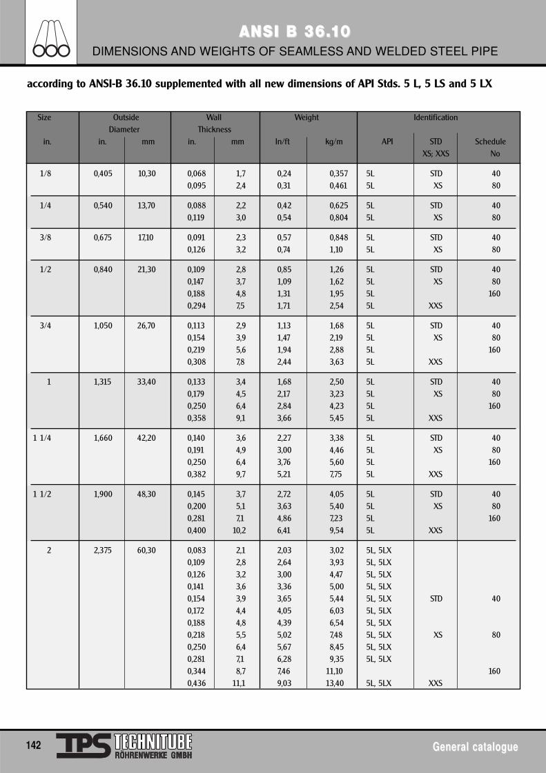
142 General catalogueGeneral catalogue
ANSI B 36.ANSI B 36.1100DIMENSIONS AND WEIGHTS OF SEAMLESS AND WELDED STEEL PIPE
according to ANSI-B 36.10 supplemented with all new dimensions of API Stds. 5 L, 5 LS and 5 LX
Size Outside Wall Weight IdentificationDiameter Thickness
in. in. mm in. mm ln/ft kg/m API STD ScheduleXS; XXS No
1/8 0,405 10,30 0,068 1,7 0,24 0,357 5L STD 400,095 2,4 0,31 0,461 5L XS 80
1/4 0,540 13,70 0,088 2,2 0,42 0,625 5L STD 400,119 3,0 0,54 0,804 5L XS 80
3/8 0,675 17,10 0,091 2,3 0,57 0,848 5L STD 400,126 3,2 0,74 1,10 5L XS 80
1/2 0,840 21,30 0,109 2,8 0,85 1,26 5L STD 400,147 3,7 1,09 1,62 5L XS 800,188 4,8 1,31 1,95 5L 1600,294 7,5 1,71 2,54 5L XXS
3/4 1,050 26,70 0,113 2,9 1,13 1,68 5L STD 400,154 3,9 1,47 2,19 5L XS 800,219 5,6 1,94 2,88 5L 1600,308 7,8 2,44 3,63 5L XXS
1 1,315 33,40 0,133 3,4 1,68 2,50 5L STD 400,179 4,5 2,17 3,23 5L XS 800,250 6,4 2,84 4,23 5L 1600,358 9,1 3,66 5,45 5L XXS
1 1/4 1,660 42,20 0,140 3,6 2,27 3,38 5L STD 400,191 4,9 3,00 4,46 5L XS 800,250 6,4 3,76 5,60 5L 1600,382 9,7 5,21 7,75 5L XXS
1 1/2 1,900 48,30 0,145 3,7 2,72 4,05 5L STD 400,200 5,1 3,63 5,40 5L XS 800,281 7,1 4,86 7,23 5L 1600,400 10,2 6,41 9,54 5L XXS
2 2,375 60,30 0,083 2,1 2,03 3,02 5L, 5LX0,109 2,8 2,64 3,93 5L, 5LX0,126 3,2 3,00 4,47 5L, 5LX0,141 3,6 3,36 5,00 5L, 5LX0,154 3,9 3,65 5,44 5L, 5LX STD 400,172 4,4 4,05 6,03 5L, 5LX0,188 4,8 4,39 6,54 5L, 5LX0,218 5,5 5,02 7,48 5L, 5LX XS 800,250 6,4 5,67 8,45 5L, 5LX0,281 7,1 6,28 9,35 5L, 5LX0,344 8,7 7,46 11,10 1600,436 11,1 9,03 13,40 5L, 5LX XXS
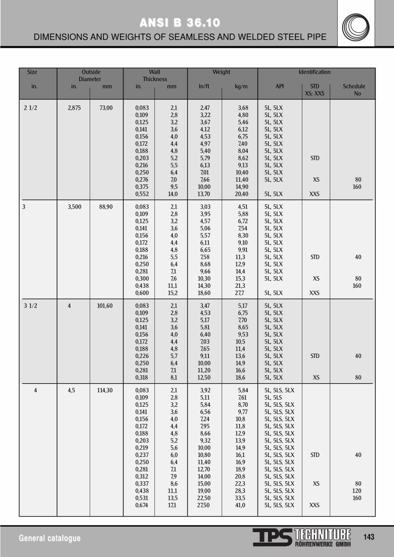
General catalogueGeneral catalogue 143
ANSI B 36.ANSI B 36.1100DIMENSIONS AND WEIGHTS OF SEAMLESS AND WELDED STEEL PIPE
Size Outside Wall Weight IdentificationDiameter Thickness
in. in. mm in. mm ln/ft kg/m API STD ScheduleXS; XXS No
2 1/2 2,875 73,00 0,083 2,1 2,47 3,68 5L, 5LX0,109 2,8 3,22 4,80 5L, 5LX0,125 3,2 3,67 5,46 5L, 5LX0,141 3,6 4,12 6,12 5L, 5LX0,156 4,0 4,53 6,75 5L, 5LX0,172 4,4 4,97 7,40 5L, 5LX0,188 4,8 5,40 8,04 5L, 5LX0,203 5,2 5,79 8,62 5L, 5LX STD0,216 5,5 6,13 9,13 5L, 5LX0,250 6,4 7,01 10,40 5L, 5LX0,276 7,0 7,66 11,40 5L, 5LX XS 800,375 9,5 10,00 14,90 1600,552 14,0 13,70 20,40 5L, 5LX XXS
3 3,500 88,90 0,083 2,1 3,03 4,51 5L, 5LX0,109 2,8 3,95 5,88 5L, 5LX0,125 3,2 4,57 6,72 5L, 5LX0,141 3,6 5,06 7,54 5L, 5LX0,156 4,0 5,57 8,30 5L, 5LX0,172 4,4 6,11 9,10 5L, 5LX0,188 4,8 6,65 9,91 5L, 5LX0,216 5,5 7,58 11,3 5L, 5LX STD 400,250 6,4 8,68 12,9 5L, 5LX0,281 7,1 9,66 14,4 5L, 5LX0,300 7,6 10,30 15,3 5L, 5LX XS 800,438 11,1 14,30 21,3 1600,600 15,2 18,60 27,7 5L, 5LX XXS
3 1/2 4 101,60 0,083 2,1 3,47 5,17 5L, 5LX0,109 2,8 4,53 6,75 5L, 5LX0,125 3,2 5,17 7,70 5L, 5LX0,141 3,6 5,81 8,65 5L, 5LX0,156 4,0 6,40 9,53 5L, 5LX0,172 4,4 7,03 10,5 5L, 5LX0,188 4,8 7,65 11,4 5L, 5LX0,226 5,7 9,11 13,6 5L, 5LX STD 400,250 6,4 10,00 14,9 5L, 5LX0,281 7,1 11,20 16,6 5L, 5LX0,318 8,1 12,50 18,6 5L, 5LX XS 80
4 4,5 114,30 0,083 2,1 3,92 5,84 5L, 5LS, 5LX0,109 2,8 5,11 7,61 5L, 5LS0,125 3,2 5,84 8,70 5L, 5LS, 5LX0,141 3,6 6,56 9,77 5L, 5LS, 5LX0,156 4,0 7,24 10,8 5L, 5LS, 5LX0,172 4,4 7,95 11,8 5L, 5LS, 5LX0,188 4,8 8,66 12,9 5L, 5LS, 5LX0,203 5,2 9,32 13,9 5L, 5LS, 5LX0,219 5,6 10,00 14,9 5L, 5LS, 5LX0,237 6,0 10,80 16,1 5L, 5LS, 5LX STD 400,250 6,4 11,40 16,9 5L, 5LS, 5LX0,281 7,1 12,70 18,9 5L, 5LS, 5LX0,312 7,9 14,00 20,8 5L, 5LS, 5LX0,337 8,6 15,00 22,3 5L, 5LS, 5LX XS 800,438 11,1 19,00 28,3 5L, 5LS, 5LX 1200,531 13,5 22,50 33,5 5L, 5LS, 5LX 1600,674 17,1 27,50 41,0 5L, 5LS, 5LX XXS
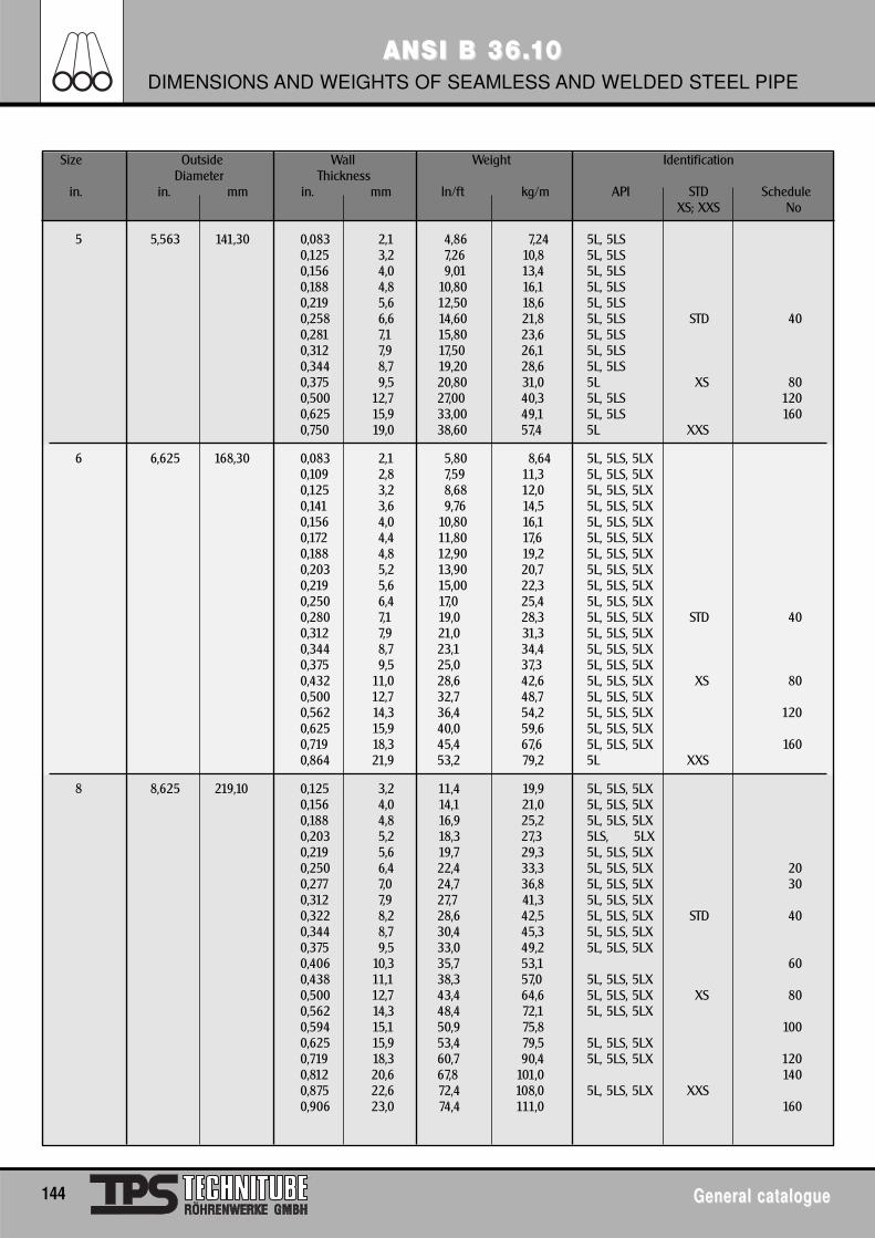
144 General catalogueGeneral catalogue
ANSI B 36.ANSI B 36.1100DIMENSIONS AND WEIGHTS OF SEAMLESS AND WELDED STEEL PIPE
Size Outside Wall Weight IdentificationDiameter Thickness
in. in. mm in. mm ln/ft kg/m API STD ScheduleXS; XXS No
5 5,563 141,30 0,083 2,1 4,86 7,24 5L, 5LS0,125 3,2 7,26 10,8 5L, 5LS0,156 4,0 9,01 13,4 5L, 5LS0,188 4,8 10,80 16,1 5L, 5LS0,219 5,6 12,50 18,6 5L, 5LS0,258 6,6 14,60 21,8 5L, 5LS STD 400,281 7,1 15,80 23,6 5L, 5LS0,312 7,9 17,50 26,1 5L, 5LS0,344 8,7 19,20 28,6 5L, 5LS0,375 9,5 20,80 31,0 5L XS 800,500 12,7 27,00 40,3 5L, 5LS 1200,625 15,9 33,00 49,1 5L, 5LS 1600,750 19,0 38,60 57,4 5L XXS
6 6,625 168,30 0,083 2,1 5,80 8,64 5L, 5LS, 5LX0,109 2,8 7,59 11,3 5L, 5LS, 5LX0,125 3,2 8,68 12,0 5L, 5LS, 5LX0,141 3,6 9,76 14,5 5L, 5LS, 5LX0,156 4,0 10,80 16,1 5L, 5LS, 5LX0,172 4,4 11,80 17,6 5L, 5LS, 5LX0,188 4,8 12,90 19,2 5L, 5LS, 5LX0,203 5,2 13,90 20,7 5L, 5LS, 5LX0,219 5,6 15,00 22,3 5L, 5LS, 5LX0,250 6,4 17,0 25,4 5L, 5LS, 5LX0,280 7,1 19,0 28,3 5L, 5LS, 5LX STD 400,312 7,9 21,0 31,3 5L, 5LS, 5LX0,344 8,7 23,1 34,4 5L, 5LS, 5LX0,375 9,5 25,0 37,3 5L, 5LS, 5LX0,432 11,0 28,6 42,6 5L, 5LS, 5LX XS 800,500 12,7 32,7 48,7 5L, 5LS, 5LX0,562 14,3 36,4 54,2 5L, 5LS, 5LX 1200,625 15,9 40,0 59,6 5L, 5LS, 5LX0,719 18,3 45,4 67,6 5L, 5LS, 5LX 1600,864 21,9 53,2 79,2 5L XXS
8 8,625 219,10 0,125 3,2 11,4 19,9 5L, 5LS, 5LX0,156 4,0 14,1 21,0 5L, 5LS, 5LX0,188 4,8 16,9 25,2 5L, 5LS, 5LX0,203 5,2 18,3 27,3 5LS, 5LX0,219 5,6 19,7 29,3 5L, 5LS, 5LX0,250 6,4 22,4 33,3 5L, 5LS, 5LX 200,277 7,0 24,7 36,8 5L, 5LS, 5LX 300,312 7,9 27,7 41,3 5L, 5LS, 5LX0,322 8,2 28,6 42,5 5L, 5LS, 5LX STD 400,344 8,7 30,4 45,3 5L, 5LS, 5LX0,375 9,5 33,0 49,2 5L, 5LS, 5LX0,406 10,3 35,7 53,1 600,438 11,1 38,3 57,0 5L, 5LS, 5LX0,500 12,7 43,4 64,6 5L, 5LS, 5LX XS 800,562 14,3 48,4 72,1 5L, 5LS, 5LX0,594 15,1 50,9 75,8 1000,625 15,9 53,4 79,5 5L, 5LS, 5LX0,719 18,3 60,7 90,4 5L, 5LS, 5LX 1200,812 20,6 67,8 101,0 1400,875 22,6 72,4 108,0 5L, 5LS, 5LX XXS0,906 23,0 74,4 111,0 160
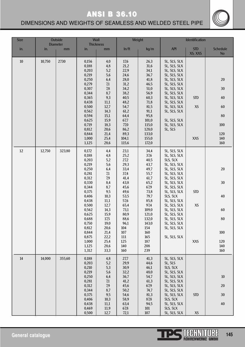
General catalogueGeneral catalogue 145
ANSI B 36.ANSI B 36.1100DIMENSIONS AND WEIGHTS OF SEAMLESS AND WELDED STEEL PIPE
Size Outside Wall Weight IdentificationDiameter Thickness
in. in. mm in. mm ln/ft kg/m API STD ScheduleXS; XXS No
10 10,750 2730 0,156 4,0 17,6 26,3 5L, 5LS, 5LX0,188 4,8 21,2 31,6 5L, 5LS, 5LX0,203 5,2 22,9 34,1 5L, 5LS, 5LX0,219 5,6 24,6 36,7 5L, 5LS, 5LX0,250 6,4 28,0 41,8 5L, 5LS, 5LX 200,279 7,1 31,2 46,5 5L, 5LS, 5LX0,307 7,8 34,2 51,0 5L, 5LS, 5LX 300,344 8,7 38,2 56,9 5L, 5LS, 5LX0,365 9,3 40,5 60,3 5L, 5LS, 5LX STD 400,438 11,1 48,2 71,8 5L, 5LS, 5LX0,500 12,7 54,7 81,5 5L, 5LS, 5LX XS 600,562 14,3 61,2 91,1 5L, 5LS, 5LX0,594 15,1 64,4 95,8 800,625 15,9 67,7 101,0 5L, 5LS, 5LX0,719 18,3 77,0 115,0 5L, 5LS, 5LX 1000,812 20,6 86,2 128,0 5L, 5LS0,844 21,4 89,3 133,0 1201,000 25,4 104,1 155,0 XXS 1401,125 28,6 115,6 172,0 160
12 12,750 323,80 0,172 4,4 23,1 34,4 5L, 5LS, 5LX0,188 4,8 25,2 37,6 5L, 5LS, 5LX0,203 5,2 27,2 40,5 5LS, 5LX0,219 5,6 29,3 43,7 5L, 5LS, 5LX0,250 6,4 33,4 49,7 5L, 5LS, 5LX 200,281 7,1 37,4 55,7 5L, 5LS, 5LX0,312 7,9 41,4 61,7 5L, 5LS, 5LX0,330 8,4 43,8 65,2 5L, 5LS, 5LX 300,344 8,7 45,6 67,9 5L, 5LS, 5LX0,375 9,5 49,6 73,8 5L, 5LS, 5LX STD0,406 10,3 53,5 79,7 5LS, 5LX 400,438 11,1 57,6 85,8 5L, 5LS, 5LX0,500 12,7 65,4 97,4 5L, 5LS, 5LX XS0,562 14,3 73,1 109,0 5L, 5LS, 5LX 600,625 15,9 80,9 121,0 5L, 5LS, 5LX0,688 17,5 88,6 132,0 5L, 5LS, 5LX 800,750 19,0 96,1 143,0 5L, 5LS, 5LX0,812 20,6 104 154 5L, 5LS, 5LX0,844 21,4 107 160 1000,875 22,2 111 165 5L, 5LS, 5LX1,000 25,4 125 187 XXS 1201,125 28,6 140 208 1401,312 33,3 160 239 160
14 14,000 355,60 0,188 4,8 27,7 41,3 5L, 5LS, 5LX0,203 5,2 29,9 44,6 5L, 5LS0,210 5,3 30,9 46,1 5LS, 5LX0,219 5,6 32,2 48,0 5L, 5LS, 5LX0,250 6,4 36,7 54,7 5L, 5LS, 5LX 100,281 7,1 41,2 61,3 5L, 5LS, 5LX0,312 7,9 45,6 67,9 5L, 5LS, 5LX 200,344 8,7 50,2 74,7 5L, 5LS, 5LX0,375 9,5 54,6 81,3 5L, 5LS, 5LX STD 300,406 10,3 58,9 87,8 5LS, 5LX0,438 11,1 63,4 94,5 5L, 5LS, 5LX 400,469 11,9 67,8 101 5LS, 5LX0,500 12,7 72,1 107 5L, 5LS, 5LX XS
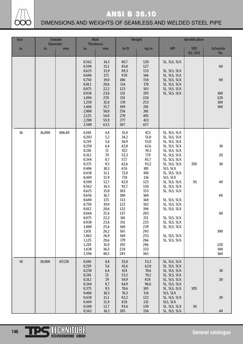
146 General catalogueGeneral catalogue
ANSI B 36.ANSI B 36.1100DIMENSIONS AND WEIGHTS OF SEAMLESS AND WELDED STEEL PIPE
Size Outside Wall Weight IdentificationDiameter Thickness
in. in. mm in. mm ln/ft kg/m API STD ScheduleXS; XXS No
0,562 14,3 80,7 120 5L, 5LS, 5LX0,594 15,1 85,0 127 600,625 15,9 89,3 133 5L, 5LS, 5LX0,688 17,5 97,8 146 5L, 5LS, 5LX0,750 19,0 106 158 5L, 5LS, 5LX 800,812 20,6 114 170 5L, 5LS, 5LX0,875 22,2 123 183 5L, 5LS, 5LX0,938 23,8 131 195 5L, 5LS, 5LX 1001,094 27,8 151 224 1201,250 31,8 170 253 1401,406 35,7 189 281 1602,000 50,8 256 3812,125 54,0 270 4012,200 55,9 277 4132,500 63,5 307 457
16 16,000 406,40 0,188 4,8 31,8 47,3 5L, 5LS, 5LX0,203 5,2 34,2 51,0 5L, 5LS, 5LX0,219 5,6 36,9 55,0 5L, 5LS, 5LX0,250 6,4 42,0 62,6 5L, 5LS, 5LX 100,281 7,1 47,2 70,3 5L, 5LS, 5LX0,312 7,9 52,3 77,9 5L, 5LS, 5LX 200,344 8,7 57,7 85,7 5L, 5LS, 5LX0,375 9,5 62,6 93,2 5L, 5LS, 5LX STD 300,406 10,3 67,6 101 5LS, 5LX0,438 11,1 72,8 108 5L, 5LS, 5LX0,469 11,9 77,8 116 5LS, 5LX0,500 12,7 82,8 123 5L, 5LS, 5LX XS 400,562 14,3 92,7 138 5L, 5LS, 5LX0,625 15,0 103 153 5L, 5LS, 5LX0,656 16,7 108 160 600,688 17,5 113 168 5L, 5LS, 5LX0,750 19,0 122 182 5L, 5LS, 5LX0,812 20,6 132 196 5L, 5LS, 5LX0,844 21,4 137 203 800,875 22,2 141 211 5L, 5LS, 5LX0,938 23,8 151 225 5L, 5LS, 5LX1,000 25,4 160 239 5L, 5LS, 5LX1,031 26,2 165 245 1001,062 26,9 169 253 5L, 5LS, 5LX1,125 28,6 179 266 5L, 5LS, 5LX1,219 31,0 192 286 1201,438 36,5 224 333 1401,594 40,5 245 365 160
18 18,000 457,20 0,188 4,8 35,8 53,3 5L, 5LS, 5LX0,219 5,6 41,6 62,0 5L, 5LS, 5LX0,250 6,4 47,4 70,6 5L, 5LS, 5LX 100,281 7,1 53,2 79,2 5L, 5LS, 5LX0,312 7,9 58,9 87,8 5L, 5LS, 5LX 200,344 8,7 64,9 96,6 5L, 5LS, 5LX0,375 9,5 70,6 105 5L, 5LS, 5LX STD0,406 10,3 76,3 114 5LS, 5LX0,438 11,1 82,2 122 5L, 5LS, 5LX 300,469 11,9 87,8 131 5LS, 5LX0,500 12,7 93,4 139 5L, 5LS, 5LX XS0,562 14,3 105 156 5L, 5LS, 5LX 40
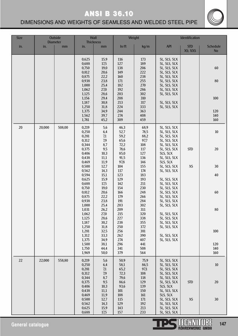
General catalogueGeneral catalogue 147
ANSI B 36.ANSI B 36.1100DIMENSIONS AND WEIGHTS OF SEAMLESS AND WELDED STEEL PIPE
Size Outside Wall Weight IdentificationDiameter Thickness
in. in. mm in. mm ln/ft kg/m API STD ScheduleXS; XXS No
0,625 15,9 116 173 5L, 5LS, 5LX0,688 17,5 127 189 5L, 5LS, 5LX0,750 19,0 138 206 5L, 5LS, 5LX 600,812 20,6 149 222 5L, 5LS, 5LX0,875 22,2 160 238 5L, 5LS, 5LX0,938 23,8 171 255 5L, 5LS, 5LX 801,000 25,4 182 270 5L, 5LS, 5LX1,062 27,0 192 286 5L, 5LS, 5LX1,125 28,6 203 302 5L, 5LS, 5LX1,156 29,4 208 310 1001,187 30,8 213 317 5L, 5LS, 5LX1,250 31,8 224 333 5L, 5LS, 5LX1,375 34,9 244 363 1201,562 39,7 274 408 1401,781 45,2 309 459 160
20 20,000 508,00 0,219 5,6 46,3 68,9 5L, 5LS, 5LX0,250 6,4 52,7 78,5 5L, 5LS, 5LX 100,281 7,1 59,2 88,2 5L, 5LS, 5LX0,312 7,9 65,6 97,7 5L, 5LS, 5LX0,344 8,7 72,2 108 5L, 5LS, 5LX0,375 9,5 78,6 117 5L, 5LS, 5LX STD 200,406 10,3 85,0 127 5LS, 5LX0,438 11,1 91,5 136 5L, 5LS, 5LX0,469 11,9 97,8 146 5LS, 5LX0,500 12,7 104 155 5L, 5LS, 5LX XS 300,562 14,3 117 174 5L, 5LS, 5LX0,594 15,1 123 183 400,625 15,9 129 193 5L, 5LS, 5LX0,688 17,5 142 211 5L, 5LS, 5LX0,750 19,0 154 230 5L, 5LS, 5LX0,812 20,6 166 248 5L, 5LS, 5LX 600,875 22,2 179 266 5L, 5LS, 5LX0,938 23,8 191 284 5L, 5LS, 5LX1,000 25,4 203 302 5L, 5LS, 5LX1,031 26,2 209 311 801,062 27,0 215 320 5L, 5LS, 5LX1,125 28,6 227 338 5L, 5LS, 5LX1,187 30,2 238 355 5L, 5LS, 5LX1,250 31,8 250 372 5L, 5LS, 5LX1,281 32,5 256 381 1001,312 33,3 262 390 5L, 5LS, 5LX1,375 34,9 274 407 5L, 5LS, 5LX1,500 38,1 296 441 1201,750 44,4 341 508 1401,969 50,0 379 564 160
22 22,000 558,80 0,219 5,6 50,9 75,9 5L, 5LS, 5LX0,250 6,4 58,1 86,5 5L, 5LS, 5LX 100,281 7,1 65,2 97,1 5L, 5LS, 5LX0,312 7,9 72,3 108 5L, 5LS, 5LX0,344 8,7 79,6 118 5L, 5LS, 5LX0,375 9,5 86,6 129 5L, 5LS, 5LX STD 200,406 10,3 93,6 139 5LS, 5LX0,438 11,1 101 150 5L, 5LS, 5LX0,469 11,9 108 161 5LS, 5LX0,500 12,7 115 171 5L, 5LS, 5LX XS 300,562 14,3 129 192 5L, 5LS, 5LX0,625 15,9 143 213 5L, 5LS, 5LX0,688 17,5 157 233 5L, 5LS, 5LX
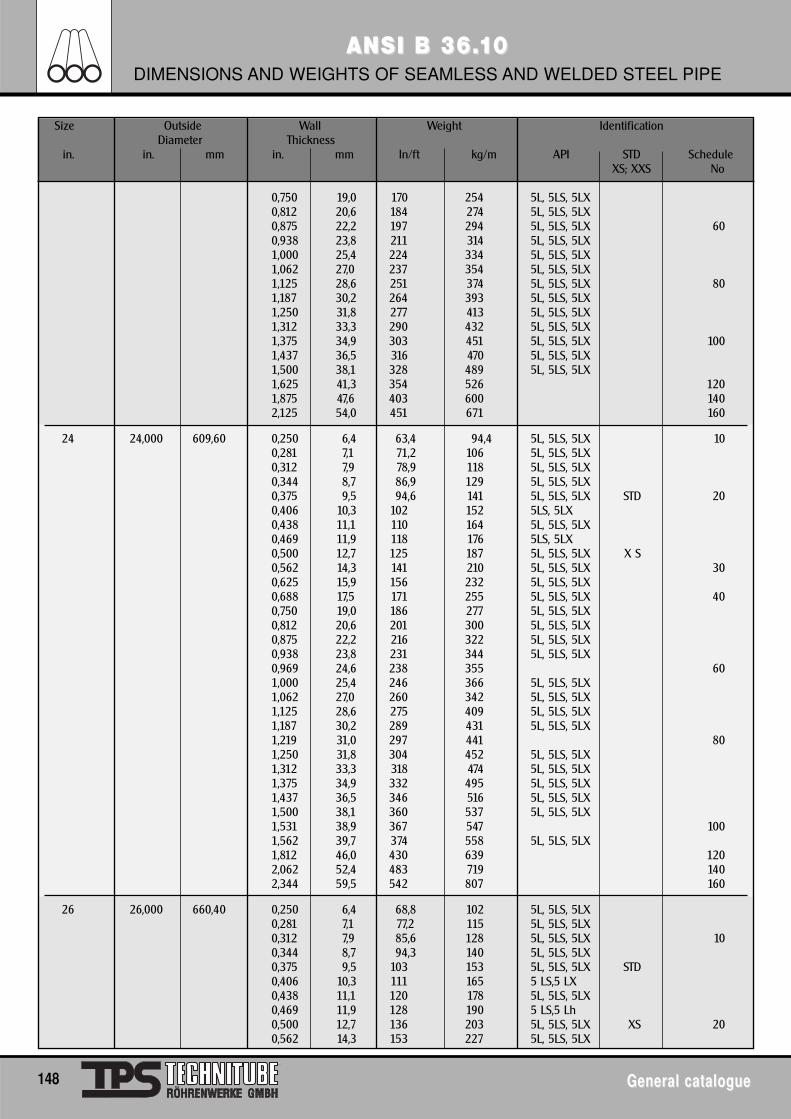
148 General catalogueGeneral catalogue
ANSI B 36.ANSI B 36.1100DIMENSIONS AND WEIGHTS OF SEAMLESS AND WELDED STEEL PIPE
Size Outside Wall Weight IdentificationDiameter Thickness
in. in. mm in. mm ln/ft kg/m API STD ScheduleXS; XXS No
0,750 19,0 170 254 5L, 5LS, 5LX0,812 20,6 184 274 5L, 5LS, 5LX0,875 22,2 197 294 5L, 5LS, 5LX 600,938 23,8 211 314 5L, 5LS, 5LX1,000 25,4 224 334 5L, 5LS, 5LX1,062 27,0 237 354 5L, 5LS, 5LX1,125 28,6 251 374 5L, 5LS, 5LX 801,187 30,2 264 393 5L, 5LS, 5LX1,250 31,8 277 413 5L, 5LS, 5LX1,312 33,3 290 432 5L, 5LS, 5LX1,375 34,9 303 451 5L, 5LS, 5LX 1001,437 36,5 316 470 5L, 5LS, 5LX1,500 38,1 328 489 5L, 5LS, 5LX1,625 41,3 354 526 1201,875 47,6 403 600 1402,125 54,0 451 671 160
24 24,000 609,60 0,250 6,4 63,4 94,4 5L, 5LS, 5LX 100,281 7,1 71,2 106 5L, 5LS, 5LX0,312 7,9 78,9 118 5L, 5LS, 5LX0,344 8,7 86,9 129 5L, 5LS, 5LX0,375 9,5 94,6 141 5L, 5LS, 5LX STD 200,406 10,3 102 152 5LS, 5LX0,438 11,1 110 164 5L, 5LS, 5LX0,469 11,9 118 176 5LS, 5LX0,500 12,7 125 187 5L, 5LS, 5LX X S0,562 14,3 141 210 5L, 5LS, 5LX 300,625 15,9 156 232 5L, 5LS, 5LX0,688 17,5 171 255 5L, 5LS, 5LX 400,750 19,0 186 277 5L, 5LS, 5LX0,812 20,6 201 300 5L, 5LS, 5LX0,875 22,2 216 322 5L, 5LS, 5LX0,938 23,8 231 344 5L, 5LS, 5LX0,969 24,6 238 355 601,000 25,4 246 366 5L, 5LS, 5LX1,062 27,0 260 342 5L, 5LS, 5LX1,125 28,6 275 409 5L, 5LS, 5LX1,187 30,2 289 431 5L, 5LS, 5LX1,219 31,0 297 441 801,250 31,8 304 452 5L, 5LS, 5LX1,312 33,3 318 474 5L, 5LS, 5LX1,375 34,9 332 495 5L, 5LS, 5LX1,437 36,5 346 516 5L, 5LS, 5LX1,500 38,1 360 537 5L, 5LS, 5LX1,531 38,9 367 547 1001,562 39,7 374 558 5L, 5LS, 5LX1,812 46,0 430 639 1202,062 52,4 483 719 1402,344 59,5 542 807 160
26 26,000 660,40 0,250 6,4 68,8 102 5L, 5LS, 5LX0,281 7,1 77,2 115 5L, 5LS, 5LX0,312 7,9 85,6 128 5L, 5LS, 5LX 100,344 8,7 94,3 140 5L, 5LS, 5LX0,375 9,5 103 153 5L, 5LS, 5LX STD0,406 10,3 111 165 5 LS,5 LX0,438 11,1 120 178 5L, 5LS, 5LX0,469 11,9 128 190 5 LS,5 Lh0,500 12,7 136 203 5L, 5LS, 5LX XS 200,562 14,3 153 227 5L, 5LS, 5LX
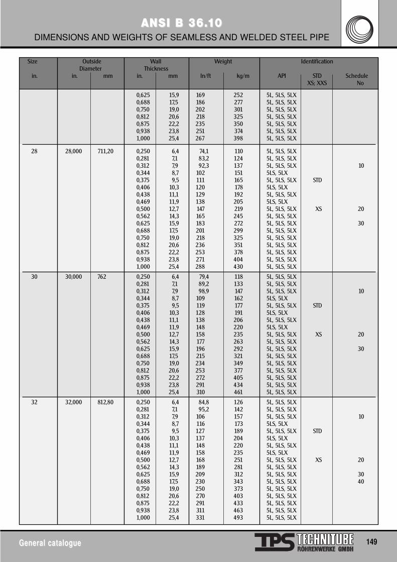
General catalogueGeneral catalogue 149
ANSI B 36.ANSI B 36.1100DIMENSIONS AND WEIGHTS OF SEAMLESS AND WELDED STEEL PIPE
Size Outside Wall Weight IdentificationDiameter Thickness
in. in. mm in. mm ln/ft kg/m API STD ScheduleXS; XXS No
0,625 15,9 169 252 5L, 5LS, 5LX0,688 17,5 186 277 5L, 5LS, 5LX0,750 19,0 202 301 5L, 5LS, 5LX0,812 20,6 218 325 5L, 5LS, 5LX0,875 22,2 235 350 5L, 5LS, 5LX0,938 23,8 251 374 5L, 5LS, 5LX1,000 25,4 267 398 5L, 5LS, 5LX
28 28,000 711,20 0,250 6,4 74,1 110 5L, 5LS, 5LX0,281 7,1 83,2 124 5L, 5LS, 5LX0,312 7,9 92,3 137 5L, 5LS, 5LX 100,344 8,7 102 151 5LS, 5LX0,375 9,5 111 165 5L, 5LS, 5LX STD0,406 10,3 120 178 5LS, 5LX0,438 11,1 129 192 5L, 5LS, 5LX0,469 11,9 138 205 5LS, 5LX0,500 12,7 147 219 5L, 5LS, 5LX XS 200,562 14,3 165 245 5L, 5LS, 5LX0,625 15,9 183 272 5L, 5LS, 5LX 300,688 17,5 201 299 5L, 5LS, 5LX0,750 19,0 218 325 5L, 5LS, 5LX0,812 20,6 236 351 5L, 5LS, 5LX0,875 22,2 253 378 5L, 5LS, 5LX0,938 23,8 271 404 5L, 5LS, 5LX1,000 25,4 288 430 5L, 5LS, 5LX
30 30,000 762 0,250 6,4 79,4 118 5L, 5LS, 5LX0,281 7,1 89,2 133 5L, 5LS, 5LX0,312 7,9 98,9 147 5L, 5LS, 5LX 100,344 8,7 109 162 5LS, 5LX0,375 9,5 119 177 5L, 5LS, 5LX STD0,406 10,3 128 191 5LS, 5LX0,438 11,1 138 206 5L, 5LS, 5LX0,469 11,9 148 220 5LS, 5LX0,500 12,7 158 235 5L, 5LS, 5LX XS 200,562 14,3 177 263 5L, 5LS, 5LX0,625 15,9 196 292 5L, 5LS, 5LX 300,688 17,5 215 321 5L, 5LS, 5LX0,750 19,0 234 349 5L, 5LS, 5LX0,812 20,6 253 377 5L, 5LS, 5LX0,875 22,2 272 405 5L, 5LS, 5LX0,938 23,8 291 434 5L, 5LS, 5LX1,000 25,4 310 461 5L, 5LS, 5LX
32 32,000 812,80 0,250 6,4 84,8 126 5L, 5LS, 5LX0,281 7,1 95,2 142 5L, 5LS, 5LX0,312 7,9 106 157 5L, 5LS, 5LX 100,344 8,7 116 173 5LS, 5LX0,375 9,5 127 189 5L, 5LS, 5LX STD0,406 10,3 137 204 5LS, 5LX0,438 11,1 148 220 5L, 5LS, 5LX0,469 11,9 158 235 5LS, 5LX0,500 12,7 168 251 5L, 5LS, 5LX XS 200,562 14,3 189 281 5L, 5LS, 5LX0,625 15,9 209 312 5L, 5LS, 5LX 300,688 17,5 230 343 5L, 5LS, 5LX 400,750 19,0 250 373 5L, 5LS, 5LX0,812 20,6 270 403 5L, 5LS, 5LX0,875 22,2 291 433 5L, 5LS, 5LX0,938 23,8 311 463 5L, 5LS, 5LX1,000 25,4 331 493 5L, 5LS, 5LX
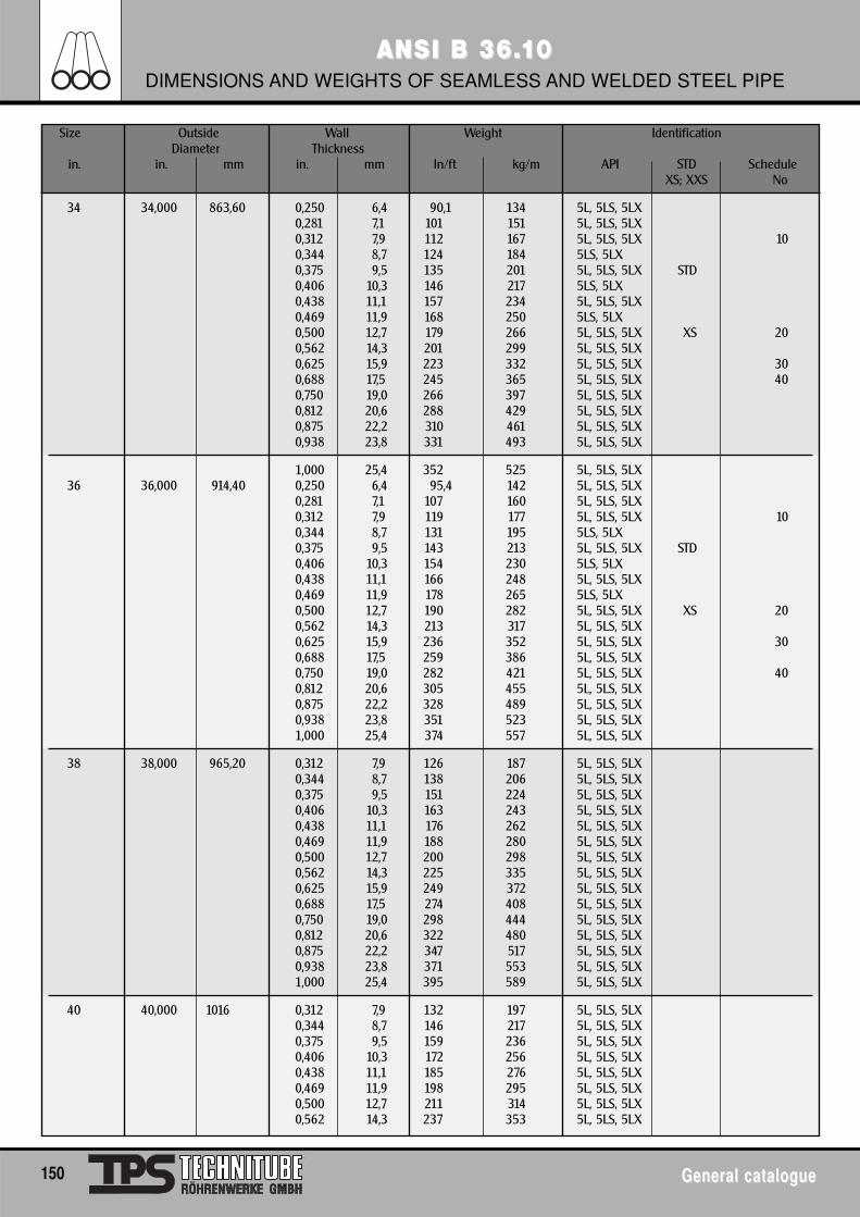
150 General catalogueGeneral catalogue
ANSI B 36.ANSI B 36.1100DIMENSIONS AND WEIGHTS OF SEAMLESS AND WELDED STEEL PIPE
Size Outside Wall Weight IdentificationDiameter Thickness
in. in. mm in. mm ln/ft kg/m API STD ScheduleXS; XXS No
34 34,000 863,60 0,250 6,4 90,1 134 5L, 5LS, 5LX0,281 7,1 101 151 5L, 5LS, 5LX0,312 7,9 112 167 5L, 5LS, 5LX 100,344 8,7 124 184 5LS, 5LX0,375 9,5 135 201 5L, 5LS, 5LX STD0,406 10,3 146 217 5LS, 5LX0,438 11,1 157 234 5L, 5LS, 5LX0,469 11,9 168 250 5LS, 5LX0,500 12,7 179 266 5L, 5LS, 5LX XS 200,562 14,3 201 299 5L, 5LS, 5LX0,625 15,9 223 332 5L, 5LS, 5LX 300,688 17,5 245 365 5L, 5LS, 5LX 400,750 19,0 266 397 5L, 5LS, 5LX0,812 20,6 288 429 5L, 5LS, 5LX0,875 22,2 310 461 5L, 5LS, 5LX0,938 23,8 331 493 5L, 5LS, 5LX
1,000 25,4 352 525 5L, 5LS, 5LX36 36,000 914,40 0,250 6,4 95,4 142 5L, 5LS, 5LX
0,281 7,1 107 160 5L, 5LS, 5LX0,312 7,9 119 177 5L, 5LS, 5LX 100,344 8,7 131 195 5LS, 5LX0,375 9,5 143 213 5L, 5LS, 5LX STD0,406 10,3 154 230 5LS, 5LX0,438 11,1 166 248 5L, 5LS, 5LX0,469 11,9 178 265 5LS, 5LX0,500 12,7 190 282 5L, 5LS, 5LX XS 200,562 14,3 213 317 5L, 5LS, 5LX0,625 15,9 236 352 5L, 5LS, 5LX 300,688 17,5 259 386 5L, 5LS, 5LX0,750 19,0 282 421 5L, 5LS, 5LX 400,812 20,6 305 455 5L, 5LS, 5LX0,875 22,2 328 489 5L, 5LS, 5LX0,938 23,8 351 523 5L, 5LS, 5LX1,000 25,4 374 557 5L, 5LS, 5LX
38 38,000 965,20 0,312 7,9 126 187 5L, 5LS, 5LX0,344 8,7 138 206 5L, 5LS, 5LX0,375 9,5 151 224 5L, 5LS, 5LX0,406 10,3 163 243 5L, 5LS, 5LX0,438 11,1 176 262 5L, 5LS, 5LX0,469 11,9 188 280 5L, 5LS, 5LX0,500 12,7 200 298 5L, 5LS, 5LX0,562 14,3 225 335 5L, 5LS, 5LX0,625 15,9 249 372 5L, 5LS, 5LX0,688 17,5 274 408 5L, 5LS, 5LX0,750 19,0 298 444 5L, 5LS, 5LX0,812 20,6 322 480 5L, 5LS, 5LX0,875 22,2 347 517 5L, 5LS, 5LX0,938 23,8 371 553 5L, 5LS, 5LX1,000 25,4 395 589 5L, 5LS, 5LX
40 40,000 1016 0,312 7,9 132 197 5L, 5LS, 5LX0,344 8,7 146 217 5L, 5LS, 5LX0,375 9,5 159 236 5L, 5LS, 5LX0,406 10,3 172 256 5L, 5LS, 5LX0,438 11,1 185 276 5L, 5LS, 5LX0,469 11,9 198 295 5L, 5LS, 5LX0,500 12,7 211 314 5L, 5LS, 5LX0,562 14,3 237 353 5L, 5LS, 5LX
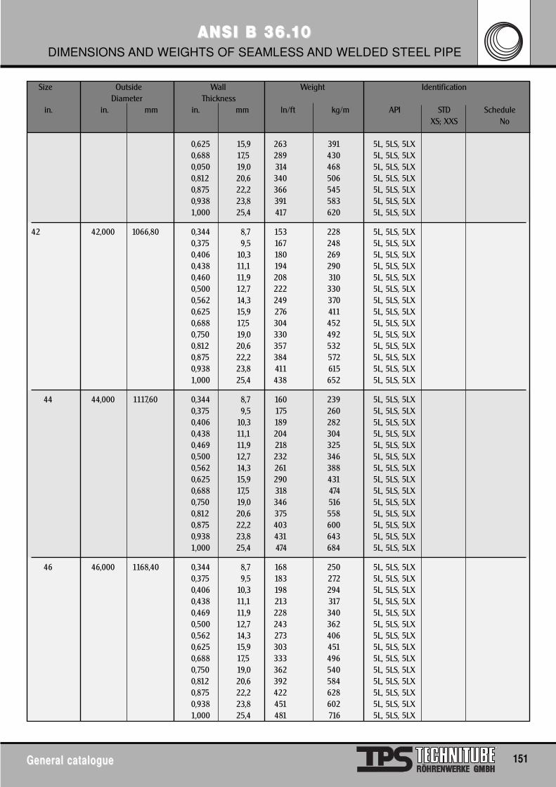
General catalogueGeneral catalogue 151
ANSI B 36.ANSI B 36.1100DIMENSIONS AND WEIGHTS OF SEAMLESS AND WELDED STEEL PIPE
Size Outside Wall Weight IdentificationDiameter Thickness
in. in. mm in. mm ln/ft kg/m API STD ScheduleXS; XXS No
0,625 15,9 263 391 5L, 5LS, 5LX0,688 17,5 289 430 5L, 5LS, 5LX0,050 19,0 314 468 5L, 5LS, 5LX0,812 20,6 340 506 5L, 5LS, 5LX0,875 22,2 366 545 5L, 5LS, 5LX0,938 23,8 391 583 5L, 5LS, 5LX1,000 25,4 417 620 5L, 5LS, 5LX
42 42,000 1066,80 0,344 8,7 153 228 5L, 5LS, 5LX0,375 9,5 167 248 5L, 5LS, 5LX0,406 10,3 180 269 5L, 5LS, 5LX0,438 11,1 194 290 5L, 5LS, 5LX0,460 11,9 208 310 5L, 5LS, 5LX0,500 12,7 222 330 5L, 5LS, 5LX0,562 14,3 249 370 5L, 5LS, 5LX0,625 15,9 276 411 5L, 5LS, 5LX0,688 17,5 304 452 5L, 5LS, 5LX0,750 19,0 330 492 5L, 5LS, 5LX0,812 20,6 357 532 5L, 5LS, 5LX0,875 22,2 384 572 5L, 5LS, 5LX0,938 23,8 411 615 5L, 5LS, 5LX1,000 25,4 438 652 5L, 5LS, 5LX
44 44,000 1117,60 0,344 8,7 160 239 5L, 5LS, 5LX0,375 9,5 175 260 5L, 5LS, 5LX0,406 10,3 189 282 5L, 5LS, 5LX0,438 11,1 204 304 5L, 5LS, 5LX0,469 11,9 218 325 5L, 5LS, 5LX0,500 12,7 232 346 5L, 5LS, 5LX0,562 14,3 261 388 5L, 5LS, 5LX0,625 15,9 290 431 5L, 5LS, 5LX0,688 17,5 318 474 5L, 5LS, 5LX0,750 19,0 346 516 5L, 5LS, 5LX0,812 20,6 375 558 5L, 5LS, 5LX0,875 22,2 403 600 5L, 5LS, 5LX0,938 23,8 431 643 5L, 5LS, 5LX1,000 25,4 474 684 5L, 5LS, 5LX
46 46,000 1168,40 0,344 8,7 168 250 5L, 5LS, 5LX0,375 9,5 183 272 5L, 5LS, 5LX0,406 10,3 198 294 5L, 5LS, 5LX0,438 11,1 213 317 5L, 5LS, 5LX0,469 11,9 228 340 5L, 5LS, 5LX0,500 12,7 243 362 5L, 5LS, 5LX0,562 14,3 273 406 5L, 5LS, 5LX0,625 15,9 303 451 5L, 5LS, 5LX0,688 17,5 333 496 5L, 5LS, 5LX0,750 19,0 362 540 5L, 5LS, 5LX0,812 20,6 392 584 5L, 5LS, 5LX0,875 22,2 422 628 5L, 5LS, 5LX0,938 23,8 451 602 5L, 5LS, 5LX1,000 25,4 481 716 5L, 5LS, 5LX
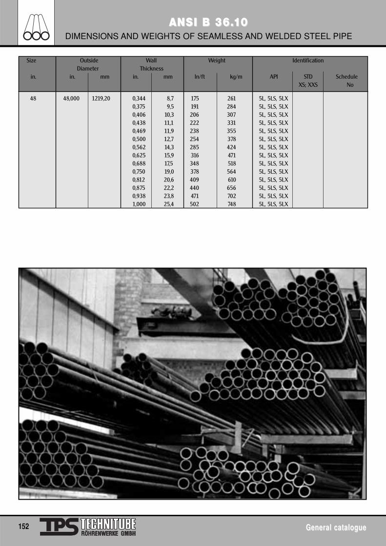
152 General catalogueGeneral catalogue
ANSI B 36.ANSI B 36.1100DIMENSIONS AND WEIGHTS OF SEAMLESS AND WELDED STEEL PIPE
Size Outside Wall Weight IdentificationDiameter Thickness
in. in. mm in. mm ln/ft kg/m API STD ScheduleXS; XXS No
48 48,000 1219,20 0,344 8,7 175 261 5L, 5LS, 5LX0,375 9,5 191 284 5L, 5LS, 5LX0,406 10,3 206 307 5L, 5LS, 5LX0,438 11,1 222 331 5L, 5LS, 5LX0,469 11,9 238 355 5L, 5LS, 5LX0,500 12,7 254 378 5L, 5LS, 5LX0,562 14,3 285 424 5L, 5LS, 5LX0,625 15,9 316 471 5L, 5LS, 5LX0,688 17,5 348 518 5L, 5LS, 5LX0,750 19,0 378 564 5L, 5LS, 5LX0,812 20,6 409 610 5L, 5LS, 5LX0,875 22,2 440 656 5L, 5LS, 5LX0,938 23,8 471 702 5L, 5LS, 5LX1,000 25,4 502 748 5L, 5LS, 5LX
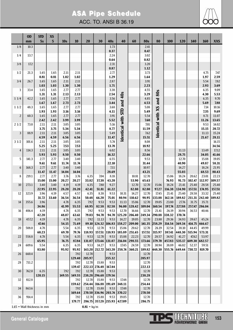
ASASA Pipe ScA Pipe Schedule hedule ACC. TO. ANSI B 36.19
General CatalogueGeneral Catalogue 153
OD STD XSmm 5s 5 10s 10 20 30 40s 40 60 80s 80 100 120 140 160 XXS
1/8 10.3 1.73 2.410.37 0.47
1/4 13.7 2.24 3.020.64 0.82
3/8 17.2 2.31 3.200.87 1.12
1/2 21.3 1.65 1.65 2.11 2.11 2.77 3.73 4.75 7.470.81 0.81 1.02 1.02 1.29 1.64 1.97 2.59
3/4 26.7 1.65 1.65 2.11 2.11 2.87 3.91 5.54 7.821.03 1.03 1.30 1.30 1.71 2.23 2.93 3.69
1 33.4 1.65 1.65 2.77 2.77 3.38 4.55 6.35 9.091.31 1.31 2.13 2.13 2.54 3.29 4.30 5.53
1 1/4 42.2 1.65 1.65 2.77 2.77 3.56 4.85 6.35 9.701.67 1.67 2.73 2.73 3.44 4.53 5.69 7.88
1 1/2 48.3 1.65 1.65 2.77 2.77 3.68 5.08 7.14 10.161.93 1.93 3.16 3.16 4.11 5.49 7.35 9.69
2 60.3 1.65 1.65 2.77 2.77 3.91 5.54 8.71 11.072.42 2.42 3.99 3.99 5.52 7.60 11.26 13.65
2 1/2 73.0 2.11 2.11 3.05 3.05 5.16 7.01 9.53 14.023.75 3.75 5.34 5.34 8.77 11.59 15.15 20.72
3 88.9 2.11 2.11 3.05 3.05 5.49 7.62 11.13 15.244.59 4.59 6.56 6.56 11.47 15.51 21.67 28.11
3 1/2 101.6 2.11 2.11 3.05 3.05 5.74 8.08 16.155.25 5.25 7.53 7.53 13.78 18.92 34.56
4 114.3 2.11 2.11 3.05 3.05 6.02 8.56 11.13 13.49 17.125.93 5.93 8.50 8.50 16.32 22.66 28.75 34.05 41.66
5 141.3 2.77 2.77 3.40 3.40 6.55 9.53 12.70 15.88 19.059.61 9.61 11.74 11.74 22.10 31.44 40.90 49.87 58.31
6 168.3 2.77 2.77 3.40 3.40 7.11 10.97 14.27 18.24 21.9511.47 11.47 14.04 14.04 28.69 43.21 55.03 68.53 80.43
8 219.1 2.77 2.77 3.76 3.76 6.35 7.04 8.18 10.81 12.70 15.06 18.24 20.62 23.01 22.2315.00 15.00 20.27 20.27 33.82 37.38 43.20 53.90 65.63 76.93 91.73 102.47 112.97 109.57
10 273.1 3.40 3.40 4.19 4.19 6.35 7.80 9.27 12.70 12.70 15.06 18.24 21.41 25.40 28.58 25.4022.95 22.95 28.20 28.20 42.41 51.81 61.22 82.80 82.80 97.27 116.38 134.90 157.51 174.95 157.51
12 323.9 3.96 4.19 4.57 4.57 6.35 8.38 9.53 10.31 14.27 12.70 17.45 21.41 25.40 28.58 33.32 25.4031.72 33.60 36.54 36.54 50.48 66.20 75.01 80.94 110.62 98.95 133.88 162.14 189.82 211.31 242.40 189.82
14 355.6 3.96 4.78 6.35 7.92 9.53 9.53 11.13 15.06 12.70 19.05 23.80 27.76 31.75 35.7134.86 41.99 55.53 68.95 82.58 82.58 96.00 128.42 109.04 160.54 197.74 227.88 257.47 286.04
16 406.4 4.19 4.78 6.35 7.92 9.53 9.53 12.70 16.66 12.70 21.41 26.19 30.94 36.53 40.4642.20 48.07 63.61 79.03 94.70 94.70 125.20 206.40 249.34 290.88 338.32 370.74
18 457.2 4.19 4.78 6.35 7.92 11.13 9.53 14.27 19.05 12.70 23.80 29.36 34.93 39.67 45.2447.46 54.15 71.69 89.10 124.32 106.83 158.27 209.00 141.35 258.29 314.54 369.34 414.75 466.67
20 508.0 4.78 5.54 6.35 9.53 12.70 9.53 15.06 20.62 12.70 26.19 32.54 38.10 44.45 49.9960.23 69.70 79.76 118.93 157.51 118.93 185.89 251.65 157.51 315.97 387.41 448.30 515.94 573.31
22 558.8 4.78 5.54 6.35 9.53 12.70 9.53 15.88 22.23 12.70 28.57 34.92 41.27 47.62 53.9765.95 76.75 87.84 131.07 173.66 131.07 216.04 298.55 173.66 379.70 457.83 535.17 609.30 682.57
24 609.6 5.54 6.35 6.35 9.53 14.27 9.53 17.45 24.59 12.70 30.94 38.89 46.02 52.37 59.5183.80 95.92 95.92 143.20 212.72 143.20 258.74 360.21 189.82 448.30 555.76 649.44 730.72 819.70
26 660.4 7.92 12.70 9.53 12.70129.40 205.97 155.32 205.97
28 711.2 7.92 12.70 15.88 9.53 12.70139.47 222.13 276.48 167.44 222.13
30 762.0 6.35 7.92 7.92 12.70 15.88 9.53 12.70120.15 149.55 149.55 238.28 296.68 179.56 238.28
32 812.8 7.92 12.70 15.88 9.53 17.48 12.70159.62 254.44 316.88 191.69 348.11 254.44
34 863.6 7.92 12.70 15.88 9.53 17.48 12.70169.64 270.50 336.96 203.74 370.22 270.50
36 914.4 7.92 12.70 15.88 9.53 19.05 12.70179.77 286.75 357.28 215.93 427.09 286.75
1.65 = Wall thickness in mm 0.81 = kg/m
Iden
tical
with
STD
and
40s
Iden
tical
with
XS
and
80s
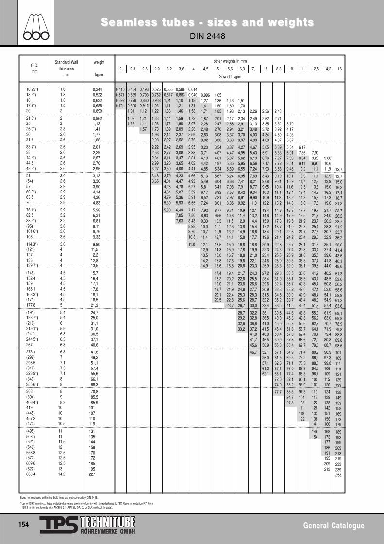
Seamless tubes - sizes and wSeamless tubes - sizes and weightseightsDIN 2448
154 General CatalogueGeneral Catalogue
O.D.mm
Standard Wallthickness
mm
weight
kg/m
other weights in mm
Gewicht kg/m
2 2,3 2,6 2,9 3,2 3,6 4 4,5 5 5,6 6,3 7,1 8 8,8 10 11 12,5 14,2 16
10,29*)13,5*)1617,2*)20
21,3*)2526,9*)3031,8
33,7*)3842,4*)44,548,3*)
51(54)5760,3*)63,570
76,1*)82,588,9*)(95)101,6*)108
114,3*)(121)127133139,7*)
(146)152,4159165,1168,3*)(171)177,8
(191)193,7*)(216)219,1*)(241)244,5*)267
273*)(292)298,5(318)323,9*)(343)355,6*)
368(394)406,4*)419(445)457,2(470)
(495)508*)(521)(546)558,8(572)609,6(622)660,4
1,61,81,81,82
222,32,62,6
2,62,62,62,62,6
2,62,62,92,92,92,9
2,93,23,23,63,63,6
3,64444
4,54,54,54,54,54,55
5,45,465,96,36,36,3
6,377,17,57,188
898,8
10101010,5
111111,51212,512,512,51314,2
0,3440,5220,6320,6880,890
0,9621,131,411,771,88
2,012,292,572,702,95
3,123,303,904,144,364,83
5,286,316,818,118,769,33
9,9011,512,212,813,5
15,716,417,117,818,118,521,3
24,725,031,131,036,537,140,6
41,649,251,157,455,666,168,3
70,885,585,9
101107110119
131135144158170172185195227
0,4100,5710,6920,754
0,4540,6390,7780,8501,01
1,091,29
0,4930,7030,8600,9421,12
1,211,441,57
0,5250,7620,9381,031,22
1,331,581,731,962,08
2,222,532,842,993,27
3,463,65
0,5550,8171,011,111,33
1,441,721,892,142,27
2,422,773,113,283,59
3,794,014,284,544,795,30
5,80
0,5880,8831,101,211,46
1,591,902,092,372,52
2,693,083,473,654,00
4,234,474,785,075,365,93
6,497,057,63
0,6140,9401,181,311,58
1,722,072,282,592,76
2,953,383,814,024,41
4,664,935,275,595,916,55
7,177,808,438,989,7010,3
11,0
0,9961,271,411,71
1,872,282,482,833,02
3,233,714,194,424,85
5,135,495,816,176,527,24
7,928,639,3310,010,711,4
12,112,913,514,214,9
1,051,361,501,85
2,012,472,703,083,30
3,544,074,614,875,34
5,676,046,416,827,218,01
8,779,5610,311,111,912,7
13,514,315,015,816,6
17,418,219,019,720,120,5
1,431,601,98
2,172,682,943,373,60
3,874,475,075,355,89
6,246,687,087,537,978,85
9,7110,611,512,313,214,1
15,015,916,717,618,5
19,420,221,121,922,422,823,7
1,511,702,13
2,342,913,213,703,97
4,274,955,625,956,55
6,957,417,918,428,919,92
10,911,912,913,814,915,8
16,817,818,819,820,8
21,722,823,824,825,325,626,7
28,729,232,633,2
2,26
2,493,133,484,034,33
4,675,436,196,567,24
7,698,218,779,349,9011,0
12,113,214,415,416,617,7
18,819,921,022,123,3
24,325,526,627,728,328,730,0
32,232,836,637,241,041,745,6
46,7
2,36
2,623,353,724,344,68
5,055,916,767,177,93
8,439,089,6510,310,912,2
13,414,615,917,218,419,6
20,922,323,424,625,9
27,228,429,630,931,532,233,4
36,136,541,041,546,046,550,9
52,126,057,161,262,1
2,43
2,713,523,924,594,97
5,396,337,277,728,56
9,109,8110,411,111,813,2
14,614,917,318,720,121,4
22,824,325,526,928,3
29,831,032,433,834,535,236,5
39,540,045,045,450,450,955,8
57,161,562,667,168,172,574,9
77,7
Sizes not enclosed within the bold lines are not covered by DIN 2448.
* Up to 139.7 mm incl., these outside diameters are in conformity with threaded pipe to ISO Recommendation R7, from168.3 mm in conformity with ANSI B 2.1, API Std 5A, 5L or 5LX (without threads).
3,704,174,935,37
5,846,917,998,519,45
10,110,911,612,413,214,8
16,317,919,521,022,624,2
25,727,428,930,332,0
33,535,136,738,239,039,741,5
44,645,350,851,657,057,863,4
64,969,571,176,077,482,185,2
88,394,797,8
6,177,368,549,1110,2
10,911,712,513,414,316,0
17,719,521,222,824,726,4
28,129,831,633,335,1
36,638,540,342,042,943,445,4
48,849,855,656,762,463,669,7
71,476,278,383,385,390,193,9
97,3104108111118122
7,909,259,9011,1
11,912,813,814,815,817,8
19,721,723,725,427,629,6
31,633,435,537,439,5
41,243,445,447,448,448,951,3
55,056,262,764,170,472,079,0
80,986,288,894,296,7102107
110118122126133138141
149154
9,8810,611,9
12,913,915,016,217,319,6
21,724,026,228,330,732,9
35,137,439,641,844,0
46,248,550,853,054,154,957,4
61,963,070,771,979,480,888,7
90,997,399,8106109115120
124139138142151156160
168173177186191195209213
12,7
13,715,016,217,418,721,2
23,726,228,731,233,736,2
38,641,443,646,148,6
51,353,656,258,659,961,263,6
69,169,878,979,888,889,898,6
101109111119121129133
138149153158169173179
189193199209213219233239253
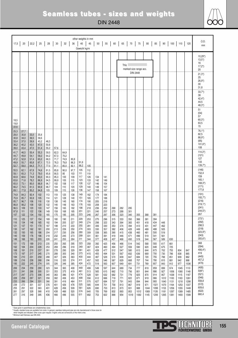
Seamless tubes - sizes and wSeamless tubes - sizes and weightseightsDIN 2448
General CatalogueGeneral Catalogue 155
1) Sizes given in parentheses are complementary sizes.2) Usually, standard sizes are available from stock. In general, seamless tubing and pipe are only manufactured in those sizes for
which weights are indicated. Other sizes upon request. English units are conversions of the metric ones. 3) Minimum wall thickness see DIN 2440.
381
394434447488500541567
593648673700755780807
8598869149669931021109911261206
18,519,822,6
25,328,030,833,436,239,0
41,744,747,249,952,7
55,558,160,963,665,066,269,1
74,975,985,786,996,597,8107
110118121130132140146
151162168173184189195
206211217228233239255261277
27,730,834,037,040,243,4
46,549,852,855,759,0
62,165,368,671,673,174,577,8
84,385,796,798,2109111122
125134137147150159166
172184191197210216222
234241247259266272291297316
33,036,539,943,547,0
50,454,157,460,864,3
67,871,374,878,280,081,585,2
92,493,9106108120122134
137148151162165176183
189204210217231238245
259266273287294301322328349
35,639,643,247,551,4
55,359,263,267,171,1
74,679,083,086,988,990,994,8
102105118120133136150
154165170181186196203
213228237245259268274
290300306321331337363368395
46,350,855,2
59,564,268,372,577,0
81,585,890,394,596,798,7103
113114130132147149165
169182187200204218226
235253261270288296305
323331340358366376401410436
57,6
62,367,371,776,381,1
85,890,595,399,9102104109
119121138140156159175
180194198213217232241
250269278288307316326
344353363382391401428438466
64,970,274,979,885,0
90,095100105108110115
125128145148165168185
190205210226230245255
265286295305326335346
365375386406416426456466496
80,886,392,1
97,7103109115117120126
138140160163182185205
211227233250256273284
295318329340363374385
408419431453464476509520555
91,898,2
105111117123126129136
149151174176198201223
229249255274280299311
323349361373400411424
449461474499511525561574611
105
112119126133137140147
162165190193218221246
253274281303309331344
358387401415444457472
499513528556570585626640682
134142146149158
174177205208236240267
275298306330338361377
392424439455487502518
549565581612627644690705753
141149154157167
184188218223252257287
296322330357365391408
425460477494529546563
597615632666684701753769822
268273306
315343353382390419437
456494512531570587607
644662682719737758813832888
282288323
333364374406415446466
486527547567609629649
689710731771791813873893954
295301340
350383394428438471493
514559580602647668691
7347567798228438679319531019
355
366401413449460496519
542590613636684707731
77780182587189491998810121082
368
381418431469481519544
568620644669720744769
819844870919944971104410691145
448462505519561589
617675702730788815843
899927957101210401070115311811265
630
661725755786851881912
97410061038110011311164125612871381
804838909942977
104510801115118312181253135513891493
8478859629981036
111011481187126112981337144914851599
O.D.mm
other weights in mm
Gewicht kg/m
17,5 20 22,2 25 28 30 32 36 40 45 50 55 60 65 70 75 80 85 90 100 110 120
10,29*)13,5*)1617,2*)20
21,3*)2526,9*)3031,8
33,7*)3842,4*)44,548,3*)
51(54)5760,3*)63,570
76,1*)82,588,9*)(95)101,6*)108
114,3*)(121)127133139,7*)
(146)152,4159165,1168,3*)(171)177,8
(191)193,7*)(216)219,1*)(241)244,5*)267
273*)(292)298,5(318)323,9*)(343)355,6*)
368(394)406,4*)419(445)457,2(470)
(495)508*)(521)(546)558,8(572)609,6(622)660,4
This marked size range acc.
DIN 2448
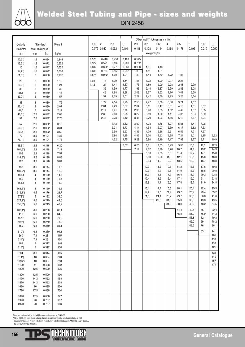
WWelded Selded Stteel Teel Tubing and Pipe - sizes and wubing and Pipe - sizes and weightseightsDIN 2458
156 General CatalogueGeneral Catalogue
Outside Standard Weight
Diameter Wall Thickness
mm mm in. kg/m
10,2*) 1,6 0,064 0,34413,5*) 1,8 0,072 0,522
16 1,8 0,072 0,63217,2*) 1,8 0,072 0,68821,3*) 2 0,080 0,962
25 2 0,080 1,1326,9*) 2 0,080 1,24
30 2 0,080 1,3931,8 2 0,080 1,48
33,7*) 2 0,080 1,57
38 2 0,080 1,7942,4*) 2 0,080 2,0144,5 2 0,080 2,11
48,3*) 2,3 0,092 2,6351 2,3 0,092 2,78
57 2,3 0,092 3,1360,3*) 2,3 0,092 3,3163,5 2,3 0,092 3,5070 2,6 0,104 4,35
76,1*) 2,6 0,104 4,75
88,9*) 2,9 0,116 6,20101,6*) 2,9 0,116 7,11
108 2,9 0,116 7,57114,3*) 3,2 0,128 8,83
127 3,2 0,128 9,84
133 3,6 0,144 11,6139,7*) 3,6 0,144 12,2152,4 4 0,160 14,7159 4 0,160 15,4
165,1 4 0,160 16,0
168,3*) 4 0,160 16,3219,1*) 4,5 0,176 23,7273*) 5 0,192 33,0
323,9*) 5,6 0,219 43,8355,6*) 5,6 0,219 48,2
406,4*) 6,3 0,250 62,4419 6,3 0,250 64,3
457,2 6,3 0,250 70,3508*) 6,3 0,250 78,2559 6,3 0,250 86,1
610*) 6,3 0,250 94,1660 7,1 0,281 115
711*) 7,1 0,281 124762 8 0,312 148
813*) 8 0,312 158
864 8,8 0,344 185914*) 10 0,394 2231016*) 10 0,394 2481120 11 0,438 3021220 12,5 0,500 375
1320 12,5 0,500 4061420 14,2 0,562 4931520 14,2 0,562 5281620 16 0,625 6301720 17,5 0,688 734
1820 17,5 0,688 7771920 20 0,787 9372020 20 0,787 986
Sizes not enclosed within the bold lines are not covered by DIN 2458.* Up to 139.7 mm incl., these outside diameters are in conformity with threaded pipe to ISO
Recommendation R 7; from 168.3 mm in conformity with threaded pipe to ANSI B 2.1, API Stds 5A,5L and 5LX (without threads).
Other Wall Thicknesses mm/in.
1,8 2 2,3 2,6 2,9 3,2 3,6 4 4,5 5 5,6 6,3
0,072 0,080 0,092 0,104 0,116 0,128 0,144 0,160 0,176 0,192 0,219 0,250
Weight kg/m
0,378 0,410 0,454 0,493 0,5250,522 0,571 0,639 0,703 0,7620,632 0,692 0,778 0,860 0,938 1,01 1,100,688 0,754 0,850 0,942 1,03 1,11 1,210,874 0,962 1,09 1,21 1,33 1,44 1,59 1,72 1,87
1,03 1,13 1,29 1,44 1,58 1,72 1,90 2,07 2,281,12 1,24 1,41 1,57 1,73 1,89 2,09 2,28 2,48 2,70
1,39 1,59 1,77 1,96 2,14 2,37 2,59 2,83 3,081,48 1,68 1,88 2,08 2,27 2,52 2,76 3,02 3,301,57 1,79 2,01 2,22 2,42 2,69 2,95 3,23 3,54
1,79 2,04 2,29 2,53 2,77 3,08 3,38 3,71 4,072,01 2,29 2,57 2,84 3,11 3,47 3,81 4,19 4,61 5,072,11 2,41 2,70 2,99 3,28 3,65 4,02 4,42 4,87 5,352,30 2,63 2,95 3,27 3,59 4,00 4,41 4,85 5,34 5,892,43 2,78 3,12 3,46 3,79 4,23 4,66 5,13 5,67 6,24
3,13 3,52 3,90 4,28 4,78 5,27 5,81 6,41 7,083,31 3,73 4,14 4,54 5,07 5,59 6,17 6,82 7,533,50 3,93 4,36 4,79 5,36 5,91 6,52 7,21 7,973,86 4,35 4,83 5,30 5,93 6,55 7,24 8,01 8,85 9,924,22 4,75 5,28 5,80 6,49 7,17 7,92 8,77 9,71 10,9
5,57 6,20 6,81 7,63 8,43 9,33 10,3 11,5 12,97,11 7,82 8,76 9,70 10,7 11,9 13,2 14,9
8,33 9,33 10,3 11,4 12,7 14,1 15,88,83 9,90 11,0 12,1 13,5 15,0 16,89,84 11,0 12,2 13,5 15,0 16,7 18,8
10,3 11,6 12,8 14,2 15,8 17,6 19,810,9 12,2 13,5 14,9 16,6 18,5 20,811,9 13,3 14,7 16,4 18,2 20,2 22,812,4 13,9 15,4 17,1 19,0 21,1 23,812,9 14,4 16,0 17,8 19,7 21,9 24,8
13,1 14,7 16,3 18,1 20,1 22,4 25,317,2 19,3 21,4 23,7 26,4 29,4 33,221,5 24,1 26,7 29,7 33,0 36,8 41,6
28,6 31,8 35,3 39,3 43,8 49,534,9 38,8 43,2 48,2 54,5
44,4 49,5 55,1 62,445,8 51,0 56,9 64,3
55,8 62,1 70,362,0 69,1 78,268,3 76,1 86,1
83,1 94,1102110118126
134142157174
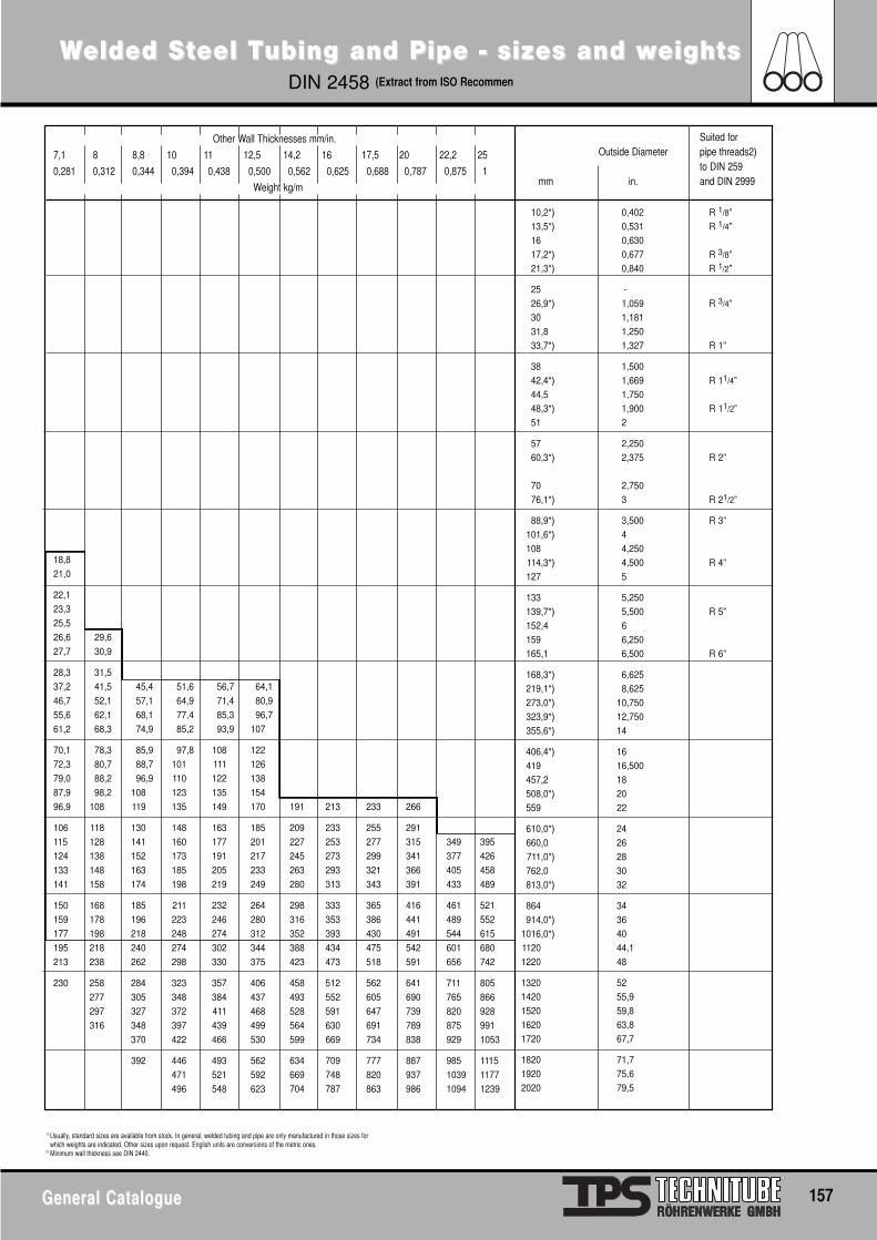
WWelded Selded Stteel Teel Tubing and Pipe - sizes and wubing and Pipe - sizes and weightseightsDIN 2458 (Extract from ISO Recommen
General CatalogueGeneral Catalogue 157
Other Wall Thicknesses mm/in.
7,1 8 8,8 10 11 12,5 14,2 16 17,5 20 22,2 25
0,281 0,312 0,344 0,394 0,438 0,500 0,562 0,625 0,688 0,787 0,875 1
Weight kg/m
18,8
21,0
22,1
23,3
25,5
26,6 29,6
27,7 30,9
28,3 31,5
37,2 41,5 45,4 51,6 56,7 64,1
46,7 52,1 57,1 64,9 71,4 80,9
55,6 62,1 68,1 77,4 85,3 96,7
61,2 68,3 74,9 85,2 93,9 107
70,1 78,3 85,9 97,8 108 122
72,3 80,7 88,7 101 111 126
79,0 88,2 96,9 110 122 138
87,9 98,2 108 123 135 154
96,9 108 119 135 149 170 191 213 233 266
106 118 130 148 163 185 209 233 255 291
115 128 141 160 177 201 227 253 277 315 349 395
124 138 152 173 191 217 245 273 299 341 377 426
133 148 163 185 205 233 263 293 321 366 405 458
141 158 174 198 219 249 280 313 343 391 433 489
150 168 185 211 232 264 298 333 365 416 461 521
159 178 196 223 246 280 316 353 386 441 489 552
177 198 218 248 274 312 352 393 430 491 544 615
195 218 240 274 302 344 388 434 475 542 601 680
213 238 262 298 330 375 423 473 518 591 656 742
230 258 284 323 357 406 458 512 562 641 711 805
277 305 348 384 437 493 552 605 690 765 866
297 327 372 411 468 528 591 647 739 820 928
316 348 397 439 499 564 630 691 789 875 991
370 422 466 530 599 669 734 838 929 1053
392 446 493 562 634 709 777 887 985 1115
471 521 592 669 748 820 937 1039 1177
496 548 623 704 787 863 986 1094 1239
Suited forOutside Diameter pipe threads2)
to DIN 259mm in. and DIN 2999
10,2*) 0,402 R 1/8”13,5*) 0,531 R 1/4”16 0,63017,2*) 0,677 R 3/8”21,3*) 0,840 R 1/2”
25 -26,9*) 1,059 R 3/4”30 1,18131,8 1,25033,7*) 1,327 R 1”
38 1,50042,4*) 1,669 R 11/4”44,5 1,75048,3*) 1,900 R 11/2”51 2
57 2,25060,3*) 2,375 R 2”
70 2,75076,1*) 3 R 21/2”
88,9*) 3,500 R 3”101,6*) 4108 4,250114,3*) 4,500 R 4”127 5
133 5,250139,7*) 5,500 R 5”152,4 6159 6,250165,1 6,500 R 6”
168,3*) 6,625219,1*) 8,625273,0*) 10,750323,9*) 12,750355,6*) 14
406,4*) 16419 16,500457,2 18508,0*) 20559 22
610,0*) 24660,0 26711,0*) 28762,0 30813,0*) 32
864 34914,0*) 36
1016,0*) 401120 44,11220 48
1320 521420 55,91520 59,81620 63,81720 67,7
1820 71,71920 75,62020 79,5
1) Usually, standard sizes are available from stock. In general, welded tubing and pipe are only manufactured in those sizes forwhich weights are indicated. Other sizes upon request. English units are conversions of the metric ones.
2) Minimum wall thickness see DIN 2440.
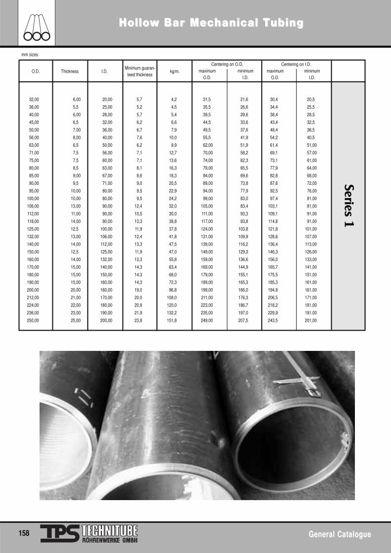
Series 1
HolloHollow Bar Mecw Bar Mechanical Thanical Tubingubing
158 General CatalogueGeneral Catalogue
mm sizes
O.D. Thickness I.D. kg/m.
Centering on O.D.maximum minimum
O.D. I.D.
Centering on I.D.maximum minimum
O.D. I.D.
32,00 6,00 20,00 5,7 4,2 31,5 21,6 30,4 20,5
36,00 5,5 25,00 5,2 4,5 35,5 26,6 34,4 25,5
40,00 6,00 28,00 5,7 5,4 39,5 29,6 38,4 28,5
45,00 6,5 32,00 6,2 6,6 44,5 33,6 43,4 32,5
50,00 7,00 36,00 6,7 7,9 49,5 37,6 48,4 36,5
56,00 8,00 40,00 7,6 10,0 55,5 41,9 54,2 40,5
63,00 6,5 50,00 6,2 9,9 62,00 51,9 61,4 51,00
71,00 7,5 56,00 7,1 12,7 70,00 58,2 69,1 57,00
75,00 7,5 60,00 7,1 13,6 74,00 62,3 73,1 61,00
80,00 8,5 63,00 8,1 16,3 79,00 65,5 77,9 64,00
85,00 9,00 67,00 8,6 18,3 84,00 69,6 82,8 68,00
90,00 9,5 71,00 9,0 20,5 89,00 73,8 87,6 72,00
95,00 10,00 80,00 9,5 22,9 94,00 77,9 92,5 76,00
100,00 10,00 80,00 9,5 24,2 99,00 83,0 97,4 81,00
106,00 13,00 90,00 12,4 32,0 105,00 83,4 103,1 81,00
112,00 11,00 90,00 10,5 30,0 111,00 93,3 109,1 91,00
118,00 14,00 90,00 13,3 38,8 117,00 93,8 114,8 91,00
125,00 12,5 100,00 11,9 37,8 124,00 103,8 121,8 101,00
132,00 13,00 106,00 12,4 41,8 131,00 109,9 128,6 107,00
140,00 14,00 112,00 13,3 47,5 139,00 116,2 136,4 113,00
150,00 12,5 125,00 11,9 47,0 149,00 129,3 146,3 126,00
160,00 14,00 132,00 13,3 55,8 159,00 136,6 156,0 133,00
170,00 15,00 140,00 14,3 63,4 169,00 144,9 165,7 141,00
180,00 15,00 150,00 14,3 68,0 179,00 155,1 175,5 151,00
190,00 15,00 160,00 14,3 72,3 189,00 165,3 185,3 161,00
200,00 20,00 160,00 19,0 96,8 199,00 166,0 194,8 161,00
212,00 21,00 170,00 20,0 108,0 211,00 176,3 206,5 171,00
224,00 22,00 180,00 20,9 120,0 223,00 186,7 218,2 181,00
236,00 23,00 190,00 21,9 132,2 235,00 197,0 229,9 191,00
250,00 25,00 200,00 23,8 151,8 249,00 207,5 243,5 201,00
Minimum guaran-teed thickness
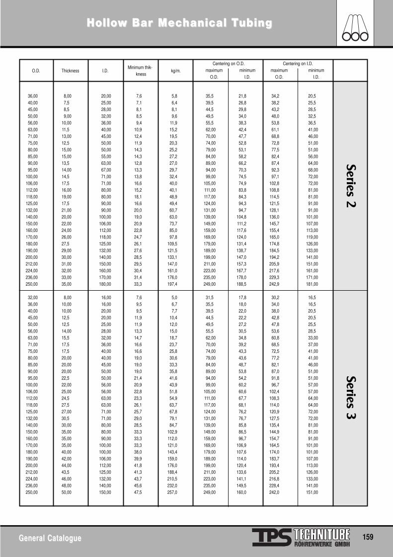
Series 3Series 2
HolloHollow Bar Mecw Bar Mechanical Thanical Tubingubing
General CatalogueGeneral Catalogue 159
O.D. Thickness I.D.Minimum thik-
knesskg/m.
Centering on O.D.maximum minimum
O.D. I.D.
Centering on I.D.maximum minimum
O.D. I.D.
36,00 8,00 20,00 7,6 5,8 35,5 21,8 34,2 20,540,00 7,5 25,00 7,1 6,4 39,5 26,8 38,2 25,545,00 8,5 28,00 8,1 8,1 44,5 29,8 43,2 28,550,00 9,00 32,00 8,5 9,6 49,5 34,0 48,0 32,556,00 10,00 36,00 9,4 11,9 55,5 38,3 53,8 36,563,00 11,5 40,00 10,9 15,2 62,00 42,4 61,1 41,0071,00 13,00 45,00 12,4 19,5 70,00 47,7 68,8 46,0075,00 12,5 50,00 11,9 20,3 74,00 52,8 72,8 51,0080,00 15,00 50,00 14,3 25,2 79,00 53,1 77,5 51,0085,00 15,00 55,00 14,3 27,2 84,00 58,2 82,4 56,0090,00 13,5 63,00 12,8 27,0 89,00 66,2 87,4 64,0095,00 14,00 67,00 13,3 29,7 94,00 70,3 92,3 68,00
100,00 14,5 71,00 13,8 32,4 99,00 74,5 97,1 72,00106,00 17,5 71,00 16,6 40,0 105,00 74,9 102,8 72,00112,00 16,00 80,00 15,2 40,1 111,00 83,8 108,8 81,00118,00 19,00 80,00 18,1 48,9 117,00 84,3 114,5 81,00125,00 17,5 90,00 16,6 49,4 124,00 94,3 121,5 91,00132,00 21,00 90,00 20,0 60,7 131,00 94,7 128,1 91,00140,00 20,00 100,00 19,0 63,0 139,00 104,8 136,0 101,00150,00 22,00 106,00 20,9 73,7 149,00 111,2 145,7 107,00160,00 24,00 112,00 22,8 85,0 159,00 117,6 155,4 113,00170,00 26,00 118,00 24,7 97,8 169,00 124,0 165,0 119,00180,00 27,5 125,00 26,1 109,5 179,00 131,4 174,8 126,00190,00 29,00 132,00 27,6 121,5 189,00 138,7 184,5 133,00200,00 30,00 140,00 28,5 133,1 199,00 147,0 194,2 141,00212,00 31,00 150,00 29,5 147,0 211,00 157,3 205,9 151,00224,00 32,00 160,00 30,4 161,0 223,00 167,7 217,6 161,00236,00 33,00 170,00 31,4 176,0 235,00 178,0 229,3 171,00250,00 35,00 180,00 33,3 197,4 249,00 188,5 242,9 181,00
32,00 8,00 16,00 7,6 5,0 31,5 17,8 30,2 16,536,00 10,00 16,00 9,5 6,7 35,5 18,0 34,0 16,540,00 10,00 20,00 9,5 7,7 39,5 22,0 38,0 20,545,00 12,5 20,00 11,9 10,4 44,5 22,2 42,8 20,550,00 12,5 25,00 11,9 12,0 49,5 27,2 47,8 25,556,00 14,00 28,00 13,3 15,0 55,5 30,5 53,6 28,563,00 15,5 32,00 14,7 18,7 62,00 34,8 60,8 33,0071,00 17,5 36,00 16,6 23,7 70,00 39,2 68,5 37,0075,00 17,5 40,00 16,6 25,8 74,00 43,3 72,5 41,0080,00 20,00 40,00 19,0 30,6 79,00 43,6 77,2 41,0085,00 20,00 45,00 19,0 33,3 84,00 48,7 82,1 46,0090,00 20,00 50,00 19,0 35,8 89,00 53,8 87,0 51,0095,00 22,5 50,00 21,4 41,6 94,00 54,2 91,8 51,00
100,00 22,00 56,00 20,9 43,9 99,00 60,2 96,7 57,00106,00 25,00 56,00 22,8 51,8 105,00 60,6 102,4 57,00112,00 24,5 63,00 23,3 54,9 111,00 67,7 108,3 64,00118,00 27,5 63,00 26,1 63,7 117,00 68,1 114,0 64,00125,00 27,00 71,00 25,7 67,8 124,00 76,2 120,9 72,00132,00 30,5 71,00 29,0 79,1 131,00 76,7 127,5 72,00140,00 30,00 80,00 28,5 84,7 139,00 85,8 135,4 81,00150,00 35,00 80,00 33,3 102,9 149,00 86,5 144,9 81,00160,00 35,00 90,00 33,3 112,0 159,00 96,7 154,7 91,00170,00 35,00 100,00 33,3 121,0 169,00 106,9 164,5 101,00180,00 40,00 100,00 38,0 143,4 179,00 107,6 174,0 101,00190,00 42,00 106,00 39,9 159,0 189,00 114,0 183,7 107,00200,00 44,00 112,00 41,8 176,0 199,00 120,4 193,4 113,00212,00 43,5 125,00 41,3 188,4 211,00 133,6 205,2 126,00224,00 46,00 132,00 43,7 210,5 223,00 141,1 216,8 133,00236,00 48,00 140,00 45,6 232,0 235,00 149,5 228,4 141,00250,00 50,00 150,00 47,5 257,0 249,00 160,0 242,0 151,00
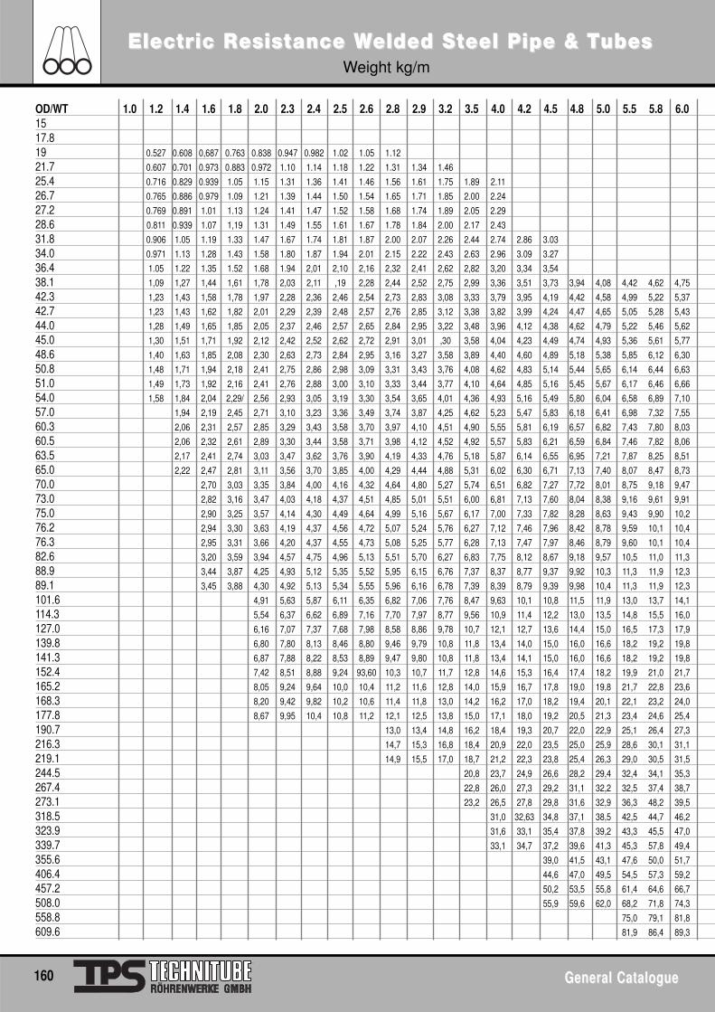
ElectrElectric Ric Resisesisttance Wance Welded Selded Stteel Pipe & Teel Pipe & TubesubesWeight kg/m
160 General CatalogueGeneral Catalogue
OD/WT 1.0 1.2 1.4 1.6 1.8 2.0 2.3 2.4 2.5 2.6 2.8 2.9 3.2 3.5 4.0 4.2 4.5 4.8 5.0 5.5 5.8 6.01517.819 0.527 0.608 0,687 0.763 0.838 0.947 0.982 1.02 1.05 1.12
21.7 0.607 0.701 0.973 0.883 0.972 1.10 1.14 1.18 1.22 1.31 1.34 1.46
25.4 0.716 0.829 0.939 1.05 1.15 1.31 1.36 1.41 1.46 1.56 1.61 1.75 1.89 2.11
26.7 0.765 0.886 0.979 1.09 1.21 1.39 1.44 1.50 1.54 1.65 1.71 1.85 2.00 2.24
27.2 0.769 0.891 1.01 1.13 1.24 1.41 1.47 1.52 1.58 1.68 1.74 1.89 2.05 2.29
28.6 0.811 0.939 1.07 1,19 1.31 1.49 1.55 1.61 1.67 1.78 1.84 2.00 2.17 2.43
31.8 0.906 1.05 1.19 1.33 1.47 1.67 1.74 1.81 1.87 2.00 2.07 2.26 2.44 2.74 2.86 3.03
34.0 0.971 1.13 1.28 1.43 1.58 1.80 1.87 1.94 2.01 2.15 2.22 2.43 2.63 2.96 3.09 3.27
36.4 1.05 1.22 1.35 1.52 1.68 1.94 2,01 2,10 2,16 2,32 2,41 2,62 2,82 3,20 3,34 3,54
38.1 1,09 1,27 1,44 1,61 1,78 2,03 2,11 ,19 2,28 2,44 2,52 2,75 2,99 3,36 3,51 3,73 3,94 4,08 4,42 4,62 4,75
42.3 1,23 1,43 1,58 1,78 1,97 2,28 2,36 2,46 2,54 2,73 2,83 3,08 3,33 3,79 3,95 4,19 4,42 4,58 4,99 5,22 5,37
42.7 1,23 1,43 1,62 1,82 2,01 2,29 2,39 2,48 2,57 2,76 2,85 3,12 3,38 3,82 3,99 4,24 4,47 4,65 5,05 5,28 5,43
44.0 1,28 1,49 1,65 1,85 2,05 2,37 2,46 2,57 2,65 2,84 2,95 3,22 3,48 3,96 4,12 4,38 4,62 4,79 5,22 5,46 5,62
45.0 1,30 1,51 1,71 1,92 2,12 2,42 2,52 2,62 2,72 2,91 3,01 ,30 3,58 4,04 4,23 4,49 4,74 4,93 5,36 5,61 5,77
48.6 1,40 1,63 1,85 2,08 2,30 2,63 2,73 2,84 2,95 3,16 3,27 3,58 3,89 4,40 4,60 4,89 5,18 5,38 5,85 6,12 6,30
50.8 1,48 1,71 1,94 2,18 2,41 2,75 2,86 2,98 3,09 3,31 3,43 3,76 4,08 4,62 4,83 5,14 5,44 5,65 6,14 6,44 6,63
51.0 1,49 1,73 1,92 2,16 2,41 2,76 2,88 3,00 3,10 3,33 3,44 3,77 4,10 4,64 4,85 5,16 5,45 5,67 6,17 6,46 6,66
54.0 1,58 1,84 2,04 2,29/ 2,56 2,93 3,05 3,19 3,30 3,54 3,65 4,01 4,36 4,93 5,16 5,49 5,80 6,04 6,58 6,89 7,10
57.0 1,94 2,19 2,45 2,71 3,10 3,23 3,36 3,49 3,74 3,87 4,25 4,62 5,23 5,47 5,83 6,18 6,41 6,98 7,32 7,55
60.3 2,06 2,31 2,57 2,85 3,29 3,43 3,58 3,70 3,97 4,10 4,51 4,90 5,55 5,81 6,19 6,57 6,82 7,43 7,80 8,03
60.5 2,06 2,32 2,61 2,89 3,30 3,44 3,58 3,71 3,98 4,12 4,52 4,92 5,57 5,83 6,21 6,59 6,84 7,46 7,82 8,06
63.5 2,17 2,41 2,74 3,03 3,47 3,62 3,76 3,90 4,19 4,33 4,76 5,18 5,87 6,14 6,55 6,95 7,21 7,87 8,25 8,51
65.0 2,22 2,47 2,81 3,11 3,56 3,70 3,85 4,00 4,29 4,44 4,88 5,31 6,02 6,30 6,71 7,13 7,40 8,07 8,47 8,73
70.0 2,70 3,03 3,35 3,84 4,00 4,16 4,32 4,64 4,80 5,27 5,74 6,51 6,82 7,27 7,72 8,01 8,75 9,18 9,47
73.0 2,82 3,16 3,47 4,03 4,18 4,37 4,51 4,85 5,01 5,51 6,00 6,81 7,13 7,60 8,04 8,38 9,16 9,61 9,91
75.0 2,90 3,25 3,57 4,14 4,30 4,49 4,64 4,99 5,16 5,67 6,17 7,00 7,33 7,82 8,28 8,63 9,43 9,90 10,2
76.2 2,94 3,30 3,63 4,19 4,37 4,56 4,72 5,07 5,24 5,76 6,27 7,12 7,46 7,96 8,42 8,78 9,59 10,1 10,4
76.3 2,95 3,31 3,66 4,20 4,37 4,55 4,73 5,08 5,25 5,77 6,28 7,13 7,47 7,97 8,46 8,79 9,60 10,1 10,4
82.6 3,20 3,59 3,94 4,57 4,75 4,96 5,13 5,51 5,70 6,27 6,83 7,75 8,12 8,67 9,18 9,57 10,5 11,0 11,3
88.9 3,44 3,87 4,25 4,93 5,12 5,35 5,52 5,95 6,15 6,76 7,37 8,37 8,77 9,37 9,92 10,3 11,3 11,9 12,3
89.1 3,45 3,88 4,30 4,92 5,13 5,34 5,55 5,96 6,16 6,78 7,39 8,39 8,79 9,39 9,98 10,4 11,3 11,9 12,3
101.6 4,91 5,63 5,87 6,11 6,35 6,82 7,06 7,76 8,47 9,63 10,1 10,8 11,5 11,9 13,0 13,7 14,1
114.3 5,54 6,37 6,62 6,89 7,16 7,70 7,97 8,77 9,56 10,9 11,4 12,2 13,0 13,5 14,8 15,5 16,0
127.0 6,16 7,07 7,37 7,68 7,98 8,58 8,86 9,78 10,7 12,1 12,7 13,6 14,4 15,0 16,5 17,3 17,9
139.8 6,80 7,80 8,13 8,46 8,80 9,46 9,79 10,8 11,8 13,4 14,0 15,0 16,0 16,6 18,2 19,2 19,8
141.3 6,87 7,88 8,22 8,53 8,89 9,47 9,80 10,8 11,8 13,4 14,1 15,0 16,0 16,6 18,2 19,2 19,8
152.4 7,42 8,51 8,88 9,24 93,60 10,3 10,7 11,7 12,8 14,6 15,3 16,4 17,4 18,2 19,9 21,0 21,7
165.2 8,05 9,24 9,64 10,0 10,4 11,2 11,6 12,8 14,0 15,9 16,7 17,8 19,0 19,8 21,7 22,8 23,6
168.3 8,20 9,42 9,82 10,2 10,6 11,4 11,8 13,0 14,2 16,2 17,0 18,2 19,4 20,1 22,1 23,2 24,0
177.8 8,67 9,95 10,4 10,8 11,2 12,1 12,5 13,8 15,0 17,1 18,0 19,2 20,5 21,3 23,4 24,6 25,4
190.7 13,0 13,4 14,8 16,2 18,4 19,3 20,7 22,0 22,9 25,1 26,4 27,3
216.3 14,7 15,3 16,8 18,4 20,9 22,0 23,5 25,0 25,9 28,6 30,1 31,1
219.1 14,9 15,5 17,0 18,7 21,2 22,3 23,8 25,4 26,3 29,0 30,5 31,5
244.5 20,8 23,7 24,9 26,6 28,2 29,4 32,4 34,1 35,3
267.4 22,8 26,0 27,3 29,2 31,1 32,2 32,5 37,4 38,7
273.1 23,2 26,5 27,8 29,8 31,6 32,9 36,3 48,2 39,5
318.5 31,0 32,63 34,8 37,1 38,5 42,5 44,7 46,2
323.9 31,6 33,1 35,4 37,8 39,2 43,3 45,5 47,0
339.7 33,1 34,7 37,2 39,6 41,3 45,3 57,8 49,4
355.6 39,0 41,5 43,1 47,6 50,0 51,7
406.4 44,6 47,0 49,5 54,5 57,3 59,2
457.2 50,2 53,5 55,8 61,4 64,6 66,7
508.0 55,9 59,6 62,0 68,2 71,8 74,3
558.8 75,0 79,1 81,8
609.6 81,9 86,4 89,3
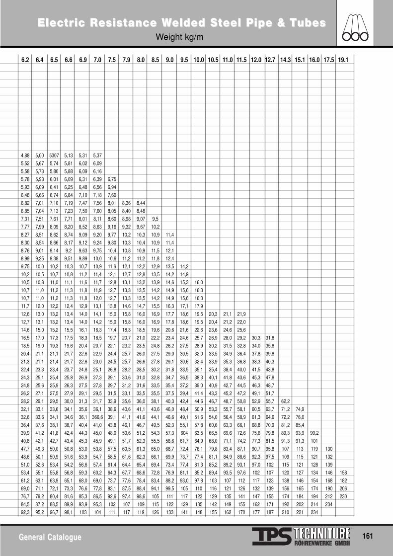
ElectrElectric Ric Resisesisttance Wance Welded Selded Stteel Pipe & Teel Pipe & TubesubesWeight kg/m
General CatalogueGeneral Catalogue 161
6.2 6.4 6.5 6.6 6.9 7.0 7.5 7.9 8.0 8.5 9.0 9.5 10.0 10.5 11.0 11.5 12.0 12.7 14.3 15.1 16.0 17.5 19.1
4,88 5,00 5307 5,13 5,31 5,37
5,52 5,67 5,74 5,81 6,02 6,09
5,58 5,73 5,80 5,88 6,09 6,16
5,78 5,93 6,01 6,09 6,31 6,39 6,75
5,93 6,09 6,41 6,25 6,48 6,56 6,94
6,48 6,66 6,74 6,84 7,10 7,18 7,60
6,82 7,01 7,10 7,19 7,47 7,56 8,01 8,36 8,44
6,85 7,04 7,13 7,23 7,50 7,60 8,05 8,40 8,48
7,31 7,51 7,61 7,71 8,01 8,11 8,60 8,98 9,07 9,5
7,77 7,99 8,09 8,20 8,52 8,63 9,16 9,32 9,67 10,2
8,27 8,51 8,62 8,74 9,09 9,20 9,77 10,2 10,3 10,9 11,4
8,30 8,54 8,66 8,17 9,12 9,24 9,80 10,3 10,4 10,9 11,4
8,76 9,01 9,14 9,2 9,63 9,75 10,4 10,8 10,9 11,5 12,1
8,99 9,25 9,38 9,51 9,89 10,0 10,6 11,2 11,2 11,8 12,4
9,75 10,0 10,2 10,3 10,7 10,9 11,6 12,1 12,2 12,9 13,5 14,2
10,2 10,5 10,7 10,8 11,2 11,4 12,1 12,7 12,8 13,5 14,2 14,9
10,5 10,8 11,0 11,1 11,6 11,7 12,8 13,1 13,2 13,9 14,6 15,3 16,0
10,7 11,0 11,2 11,3 11,8 11,9 12,7 13,3 13,5 14,2 14,9 15,6 16,3
10,7 11,0 11,2 11,3 11,8 12,0 12,7 13,3 13,5 14,2 14,9 15,6 16,3
11,7 12,0 12,2 12,4 12,9 13,1 13,8 14,6 14,7 15,5 16,3 17,1 17,9
12,6 13,0 13,2 13,4 14,0 14,1 15,0 15,8 16,0 16,9 17,7 18,6 19,5 20,3 21,1 21,9
12,7 13,1 13,2 13,4 14,0 14,2 15,0 15,8 16,0 16,9 17,8 18,6 19,5 20,4 21,2 22,0
14,6 15,0 15,2 15,5 16,1 16,3 17,4 18,3 18,5 19,6 20,6 21,6 22,6 23,6 24,6 25,6
16,5 17,0 17,3 17,5 18,3 18,5 19,7 20,7 21,0 22,2 23,4 24,6 25,7 26,9 28,0 29,2 30,3 31,8
18,5 19,0 19,3 19,6 20,4 20,7 22,1 23,2 23,5 24,8 26,2 27,5 28,9 30,2 31,5 32,8 34,0 35,8
20,4 21,1 21,1 21,7 22,6 22,9 24,4 25,7 26,0 27,5 29,0 30,5 32,0 33,5 34,9 36,4 37,8 39,8
21,3 21,1 21,4 21,7 22,6 23,0 24,5 25,7 26,6 27,8 29,1 30,6 32,4 33,9 35,3 36,8 38,3 40,3
22,4 23,3 23,4 23,7 24,8 25,1 26,8 28,2 28,5 30,2 31,8 33,5 35,1 35,4 38,4 40,0 41,5 43,8
24,3 25,1 25,4 25,8 26,9 27,3 29,1 30,6 31,0 32,8 34,7 36,5 38,3 40,1 41,8 43,6 45,3 47,8
24,8 25,6 25,9 26,3 27,5 27,8 29,7 31,2 31,6 33,5 35,4 37,2 39,0 40,9 42,7 44,5 46,3 48,7
26,2 27,1 27,5 27,9 29,1 29,5 31,5 33,1 33,5 35,5 37,5 39,4 41,4 43,3 45,2 47,2 49,1 51,7
28,2 29,1 29,5 30,0 31,3 31,7 33,9 35,6 36,0 38,1 40,3 42,4 44,6 46,7 48,7 50,8 52,9 55,7 62,2
32,1 33,1 33,6 34,1 35,6 36,1 38,6 40,6 41,1 43,6 46,0 48,4 50,9 53,3 55,7 58,1 60,5 63,7 71,2 74,9
32,6 33,6 34,1 34,6 36,1 366,6 39,1 41,1 41,6 44,1 46,6 49,1 51,6 54,0 56,4 58,9 61,3 64,6 72,2 76,0
36,4 37,6 38,1 38,7 40,4 41,0 43,8 46,1 46,7 49,5 52,3 55,1 57,8 60,6 63,3 66,1 68,8 70,9 81,2 85,4
39,9 41,2 41,8 42,4 44,3 45,0 48,0 50,6 51,2 54,3 57,3 604 63,5 66,5 69,6 72,6 75,6 79,8 89,3 93,9 99,2
40,8 42,1 42,7 43,4 45,3 45,9 49,1 51,7 52,3 55,5 58,6 61,7 64,9 68,0 71,1 74,2 77,3 81,5 91,3 91,3 101
47,7 49,3 50,0 50,8 53,0 53,8 57,5 60,5 61,3 65,0 68,7 72,4 76,1 79,8 83,4 87,1 90,7 95,8 107 113 119 130
48,6 50,1 50,9 51,6 53,9 54,7 58,5 61,6 62,3 66,1 69,9 73,7 77,4 81,1 84,9 88,6 92,3 97,5 109 115 121 132
51,0 52,6 53,4 54,2 56,6 57,4 61,4 64,4 65,4 69,4 73,4 77,4 81,3 85,2 89,2 93,1 97,0 102 115 121 128 139
53,4 55,1 55,8 56,8 59,3 60,2 64,3 67,7 68,6 72,8 76,9 81,1 85,2 89,4 93,5 97,6 102 107 120 127 134 146 158
61,2 63,1 63,9 65,1 68,0 69,0 73,7 77,6 78,4 83,4 88,2 93,0 97,8 103 107 112 117 123 138 146 154 168 182
69,0 71,1 72,1 73,3 76,6 77,8 83,1 87,5 88,4 94,1 99,5 105 110 116 121 126 132 139 156 165 174 190 206
76,7 79,2 80,4 81,6 85,3 86,5 92,6 97,4 98,6 105 111 117 123 129 135 141 147 155 174 184 194 212 230
84,5 87,2 88,5 89,9 93,9 95,3 102 107 109 115 122 129 135 142 149 155 162 171 192 202 214 234
92,3 95,2 96,7 98,1 103 104 111 117 119 126 133 141 148 155 162 170 177 187 210 221 234
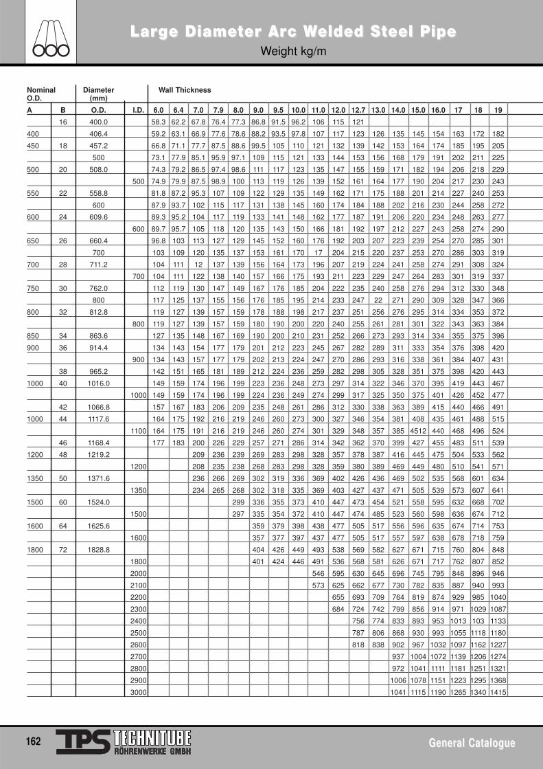
Nominal Diameter Wall ThicknessO.D. (mm)
A B O.D. I.D. 6.0 6.4 7.0 7.9 8.0 9.0 9.5 10.0 11.0 12.0 12.7 13.0 14.0 15.0 16.0 17 18 19
16 400.0 58.3 62.2 67.8 76.4 77.3 86.8 91.5 96.2 106 115 121
400 406.4 59.2 63.1 66.9 77.6 78.6 88.2 93.5 97.8 107 117 123 126 135 145 154 163 172 182
450 18 457.2 66.8 71.1 77.7 87.5 88.6 99.5 105 110 121 132 139 142 153 164 174 185 195 205
500 73.1 77.9 85.1 95.9 97.1 109 115 121 133 144 153 156 168 179 191 202 211 225
500 20 508.0 74.3 79.2 86.5 97.4 98.6 111 117 123 135 147 155 159 171 182 194 206 218 229
500 74.9 79.9 87.5 98.9 100 113 119 126 139 152 161 164 177 190 204 217 230 243
550 22 558.8 81.8 87.2 95.3 107 109 122 129 135 149 162 171 175 188 201 214 227 240 253
600 87.9 93.7 102 115 117 131 138 145 160 174 184 188 202 216 230 244 258 272
600 24 609.6 89.3 95.2 104 117 119 133 141 148 162 177 187 191 206 220 234 248 263 277
600 89.7 95.7 105 118 120 135 143 150 166 181 192 197 212 227 243 258 274 290
650 26 660.4 96.8 103 113 127 129 145 152 160 176 192 203 207 223 239 254 270 285 301
700 103 109 120 135 137 153 161 170 17 204 215 220 237 253 270 286 303 319
700 28 711.2 104 111 12 137 139 156 164 173 196 207 219 224 241 258 274 291 308 324
700 104 111 122 138 140 157 166 175 193 211 223 229 247 264 283 301 319 337
750 30 762.0 112 119 130 147 149 167 176 185 204 222 235 240 258 276 294 312 330 348
800 117 125 137 155 156 176 185 195 214 233 247 22 271 290 309 328 347 366
800 32 812.8 119 127 139 157 159 178 188 198 217 237 251 256 276 295 314 334 353 372
800 119 127 139 157 159 180 190 200 220 240 255 261 281 301 322 343 363 384
850 34 863.6 127 135 148 167 169 190 200 210 231 252 266 273 293 314 334 355 375 396
900 36 914.4 134 143 154 177 179 201 212 223 245 267 282 289 311 333 354 376 398 420
900 134 143 157 177 179 202 213 224 247 270 286 293 316 338 361 384 407 431
38 965.2 142 151 165 181 189 212 224 236 259 282 298 305 328 351 375 398 420 443
1000 40 1016.0 149 159 174 196 199 223 236 248 273 297 314 322 346 370 395 419 443 467
1000 149 159 174 196 199 224 236 249 274 299 317 325 350 375 401 426 452 477
42 1066.8 157 167 183 206 209 235 248 261 286 312 330 338 363 389 415 440 466 491
1000 44 1117.6 164 175 192 216 219 246 260 273 300 327 346 354 381 408 435 461 488 515
1100 164 175 191 216 219 246 260 274 301 329 348 357 385 4512 440 468 496 524
46 1168.4 177 183 200 226 229 257 271 286 314 342 362 370 399 427 455 483 511 539
1200 48 1219.2 209 236 239 269 283 298 328 357 378 387 416 445 475 504 533 562
1200 208 235 238 268 283 298 328 359 380 389 469 449 480 510 541 571
1350 50 1371.6 236 266 269 302 319 336 369 402 426 436 469 502 535 568 601 634
1350 234 265 268 302 318 335 369 403 427 437 471 505 539 573 607 641
1500 60 1524.0 299 336 355 373 410 447 473 454 521 558 595 632 668 702
1500 297 335 354 372 410 447 474 485 523 560 598 636 674 712
1600 64 1625.6 359 379 398 438 477 505 517 556 596 635 674 714 753
1600 357 377 397 437 477 505 517 557 597 638 678 718 759
1800 72 1828.8 404 426 449 493 538 569 582 627 671 715 760 804 848
1800 401 424 446 491 536 568 581 626 671 717 762 807 852
2000 546 595 630 645 696 745 795 846 896 946
2100 573 625 662 677 730 782 835 887 940 993
2200 655 693 709 764 819 874 929 985 1040
2300 684 724 742 799 856 914 971 1029 1087
2400 756 774 833 893 953 1013 103 1133
2500 787 806 868 930 993 1055 1118 1180
2600 818 838 902 967 1032 1097 1162 1227
2700 937 1004 1072 1139 1206 1274
2800 972 1041 1111 1181 1251 1321
2900 1006 1078 1151 1223 1295 1368
3000 1041 1115 1190 1265 1340 1415
LarLargge Diamee Diametter Arer Arc Wc Welded Selded Stteel Pipeeel PipeWeight kg/m
162 General CatalogueGeneral Catalogue
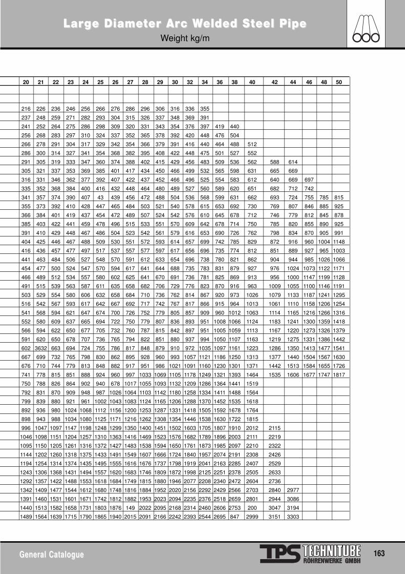
LarLargge Diamee Diametter Arer Arc Wc Welded Selded Stteel Pipeeel PipeWeight kg/m
General CatalogueGeneral Catalogue 163
20 21 22 23 24 25 26 27 28 29 30 32 34 36 38 40 42 44 46 48 50
216 226 236 246 256 266 276 286 296 306 316 336 355
237 248 259 271 282 293 304 315 326 337 348 369 391
241 252 264 275 286 298 309 320 331 343 354 376 397 419 440
256 268 283 297 310 324 337 352 365 378 392 420 448 476 504
266 278 291 304 317 329 342 354 366 379 391 416 440 464 488 512
286 300 314 327 341 354 368 382 395 408 422 448 475 501 527 552
291 305 319 333 347 360 374 388 402 415 429 456 483 509 536 562 588 614
305 321 337 353 369 385 401 417 434 450 466 499 532 565 598 631 665 669
316 331 346 362 377 392 407 422 437 452 466 496 525 554 583 612 640 669 697
335 352 368 384 400 416 432 448 464 480 489 527 560 589 620 651 682 712 742
341 357 374 390 407 43 439 456 472 488 504 536 568 599 631 662 693 724 755 785 815
355 373 392 410 428 447 465 484 503 521 540 578 615 653 692 730 769 807 846 885 925
366 384 401 419 437 454 472 489 507 524 542 576 610 645 678 712 746 779 812 845 878
385 403 422 441 459 478 496 515 533 551 570 609 642 678 714 750 785 820 855 890 925
391 410 429 448 467 486 504 523 542 561 579 616 653 690 726 762 798 834 870 905 991
404 425 446 467 488 509 530 551 572 593 614 657 699 742 785 829 872 916 960 1004 1148
416 436 457 477 497 517 537 557 577 597 617 656 696 735 774 812 851 889 927 965 1003
441 463 484 506 527 548 570 591 612 633 654 696 738 780 821 862 904 944 985 1026 1066
454 477 500 524 547 570 594 617 641 644 688 735 783 831 879 927 976 1024 1073 1122 1171
466 489 512 534 557 580 602 625 641 670 691 736 781 825 869 913 956 1000 1147 1199 1128
491 515 539 563 587 611 635 658 682 706 729 776 823 870 916 963 1009 1055 1100 1146 1191
503 529 554 580 606 632 658 684 710 736 762 814 867 920 973 1026 1079 1133 1187 1241 1295
516 542 567 593 617 642 667 692 717 742 767 817 866 915 964 1013 1061 1110 1158 1206 1254
541 568 594 621 647 674 700 726 752 779 805 857 909 960 1012 1063 1114 1165 1216 1266 1316
552 580 609 637 665 694 722 750 779 807 836 893 951 1008 1066 1124 1183 1241 1300 1359 1418
566 594 622 650 677 705 732 760 787 815 842 897 951 1005 1059 1113 1167 1220 1273 1326 1379
591 620 650 678 707 736 765 794 822 851 880 937 994 1050 1107 1163 1219 1275 1331 1386 1442
602 3632 663 694 724 755 786 817 848 879 910 972 1035 1097 1161 1223 1286 1350 1413 1477 1541
667 699 732 765 798 830 862 895 928 960 993 1057 1121 1186 1250 1313 1377 1440 1504 1567 1630
676 710 744 779 813 848 882 917 951 986 1021 1091 1160 1230 1301 1371 1442 1513 1584 1655 1726
741 778 815 851 888 924 960 997 1033 1069 1105 1178 1249 1321 1393 1464 1535 1606 1677 1747 1817
750 788 826 864 902 940 678 1017 1055 1093 1132 1209 1286 1364 1441 1519
792 831 870 909 948 987 1026 1064 1103 1142 1180 1258 1334 1411 1488 1564
799 839 880 921 961 1002 1043 1083 1124 1165 1206 1288 1370 1452 1535 1618
892 936 980 1024 1068 1112 1156 1200 1253 1287 1331 1418 1505 1592 1678 1764
898 943 988 1034 1080 1125 1171 1216 1262 1308 1354 1446 1538 1630 1722 1815
996 1047 1097 1147 1198 1248 1299 1350 1400 1451 1502 1603 1705 1807 1910 2012 2115
1046 1098 1151 1204 1257 1310 1363 1416 1469 1523 1576 1682 1789 1896 2003 2111 2219
1095 1150 1205 1261 1316 1372 1427 1483 1538 1594 1650 1761 1873 1985 2097 2210 2322
1144 1202 1260 1318 1375 1433 1491 1549 1607 1666 1724 1840 1957 2074 2191 2308 2426
1194 1254 1314 1374 1435 1495 1555 1616 1676 1737 1798 1919 2041 2163 2285 2407 2529
1243 1306 1368 1431 1494 1557 1620 1683 1746 1809 1872 1998 2125 2251 2378 2505 2633
1292 1357 1422 1488 1553 1618 1684 1749 1815 1880 1946 2077 2208 2340 2472 2604 2736
1342 1409 1477 1544 1612 1680 1748 1816 1884 1952 2020 2156 2292 2429 2566 2703 2840 2977
1391 1460 1531 1601 1671 1742 1812 1882 1953 2023 2094 2235 2376 2518 2659 2801 2944 3086
1440 1513 1582 1658 1731 1803 1876 149 2022 2095 2168 2314 2460 2606 2753 200 3047 3194
1489 1564 1639 1715 1790 1865 1940 2015 2091 2166 2242 2393 2544 2695 847 2999 3151 3303
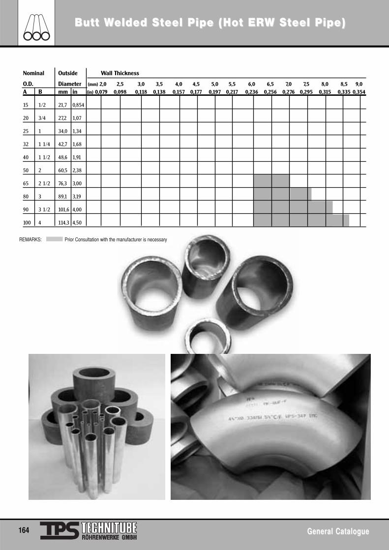
Butt WButt Welded Selded Stteel Pipe (Hot EReel Pipe (Hot ERW SW Stteel Pipe)eel Pipe)
164 General CatalogueGeneral Catalogue
Nominal Outside Wall Thickness
O.D. Diameter (mm) 2,0 2,5 3,0 3,5 4,0 4,5 5,0 5,5 6,0 6,5 7,0 7,5 8,0 8,5 9,0A B mm in (in) 0,079 0,098 0,118 0,138 0,157 0,177 0,197 0,217 0,236 0,256 0,276 0,295 0,315 0,335 0,354
15 1/2 21,7 0,854
20 3/4 27,2 1,07
25 1 34,0 1,34
32 1 1/4 42,7 1,68
40 1 1/2 48,6 1,91
50 2 60,5 2,38
65 2 1/2 76,3 3,00
80 3 89,1 3,19
90 3 1/2 101,6 4,00
100 4 114,3 4,50
REMARKS: Prior Consultation with the manufacturer is necessary
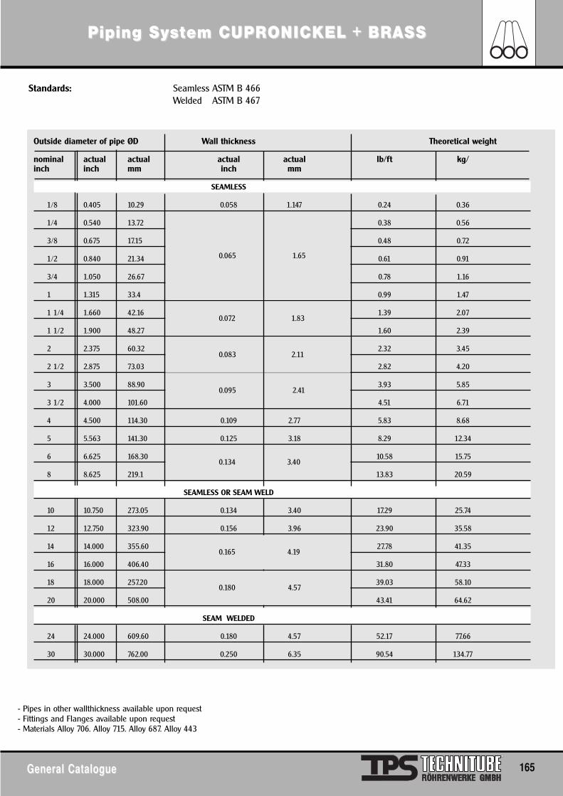
Piping SyPiping Syssttem CUPRem CUPRONICONICKEL + BRASSKEL + BRASS
General CatalogueGeneral Catalogue 165
Standards: Seamless ASTM B 466Welded ASTM B 467
- Pipes in other wallthickness available upon request- Fittings and Flanges available upon request- Materials Alloy 706. Alloy 715. Alloy 687. Alloy 443
Outside diameter of pipe ØD Wall thickness Theoretical weight
nominal actual actual actual actual lb/ft kg/inch inch mm inch mm
SEAMLESS
1/8 0.405 10.29 0.058 1.147 0.24 0.36
1/4 0.540 13.72 0.38 0.56
3/8 0.675 17.15 0.48 0.72
1/2 0.840 21.34 0.61 0.91
3/4 1.050 26.67 0.78 1.16
1 1.315 33.4 0.99 1.47
1 1/4 1.660 42.16 1.39 2.07
1 1/2 1.900 48.27 1.60 2.39
2 2.375 60.32 2.32 3.45
2 1/2 2.875 73.03 2.82 4.20
3 3.500 88.90 3.93 5.85
3 1/2 4.000 101.60 4.51 6.71
4 4.500 114.30 0.109 2.77 5.83 8.68
5 5.563 141.30 0.125 3.18 8.29 12.34
6 6.625 168.30 10.58 15.75
8 8.625 219.1 13.83 20.59
SEAMLESS OR SEAM WELD
10 10.750 273.05 0.134 3.40 17.29 25.74
12 12.750 323.90 0.156 3.96 23.90 35.58
14 14.000 355.60 27.78 41.35
16 16.000 406.40 31.80 47.33
18 18.000 257.20 39.03 58.10
20 20.000 508.00 43.41 64.62
SEAM WELDED
24 24.000 609.60 0.180 4.57 52.17 77.66
30 30.000 762.00 0.250 6.35 90.54 134.77
0.065 1.65
0.072 1.83
0.083 2.11
0.095 2.41
0.134 3.40
0.180 4.57
0.165 4.19
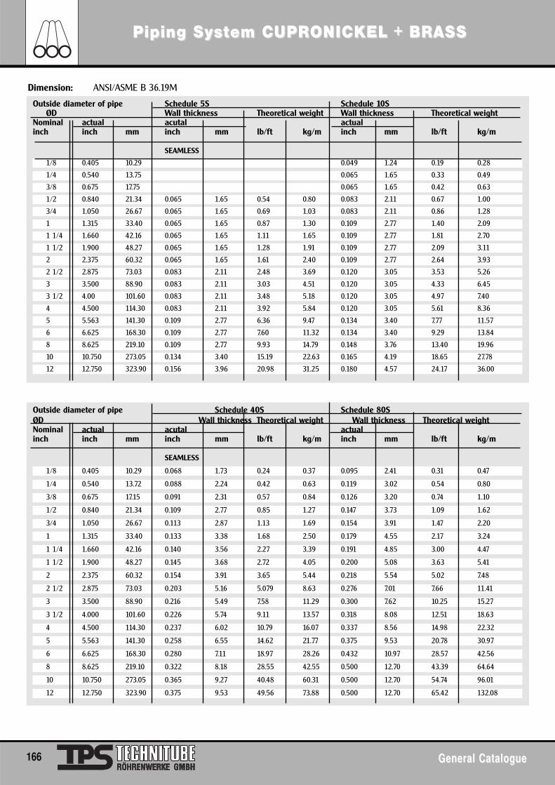
Outside diameter of pipe Schedule 40S Schedule 80SØD Wall thickness Theoretical weight Wall thickness Theoretical weightNominal actual acutal actualinch inch mm inch mm lb/ft kg/m inch mm lb/ft kg/m
SEAMLESS
1/8 0.405 10.29 0.068 1.73 0.24 0.37 0.095 2.41 0.31 0.47
1/4 0.540 13.72 0.088 2.24 0.42 0.63 0.119 3.02 0.54 0.80
3/8 0.675 17.15 0.091 2.31 0.57 0.84 0.126 3.20 0.74 1.10
1/2 0.840 21.34 0.109 2.77 0.85 1.27 0.147 3.73 1.09 1.62
3/4 1.050 26.67 0.113 2.87 1.13 1.69 0.154 3.91 1.47 2.20
1 1.315 33.40 0.133 3.38 1.68 2.50 0.179 4.55 2.17 3.24
1 1/4 1.660 42.16 0.140 3.56 2.27 3.39 0.191 4.85 3.00 4.47
1 1/2 1.900 48.27 0.145 3.68 2.72 4.05 0.200 5.08 3.63 5.41
2 2.375 60.32 0.154 3.91 3.65 5.44 0.218 5.54 5.02 7.48
2 1/2 2.875 73.03 0.203 5.16 5.079 8.63 0.276 7.01 7.66 11.41
3 3.500 88.90 0.216 5.49 7.58 11.29 0.300 7.62 10.25 15.27
3 1/2 4.000 101.60 0.226 5.74 9.11 13.57 0.318 8.08 12.51 18.63
4 4.500 114.30 0.237 6.02 10.79 16.07 0.337 8.56 14.98 22.32
5 5.563 141.30 0.258 6.55 14.62 21.77 0.375 9.53 20.78 30.97
6 6.625 168.30 0.280 7.11 18.97 28.26 0.432 10.97 28.57 42.56
8 8.625 219.10 0.322 8.18 28.55 42.55 0.500 12.70 43.39 64.64
10 10.750 273.05 0.365 9.27 40.48 60.31 0.500 12.70 54.74 96.01
12 12.750 323.90 0.375 9.53 49.56 73.88 0.500 12.70 65.42 132.08
Piping SyPiping Syssttem CUPRem CUPRONICONICKEL + BRASSKEL + BRASS
166 General CatalogueGeneral Catalogue
Outside diameter of pipe Schedule 5S Schedule 10SØD Wall thickness Theoretical weight Wall thickness Theoretical weight
Nominal actual acutal actualinch inch mm inch mm lb/ft kg/m inch mm lb/ft kg/m
SEAMLESS
1/8 0.405 10.29 0.049 1.24 0.19 0.28
1/4 0.540 13.75 0.065 1.65 0.33 0.49
3/8 0.675 17.75 0.065 1.65 0.42 0.63
1/2 0.840 21.34 0.065 1.65 0.54 0.80 0.083 2.11 0.67 1.00
3/4 1.050 26.67 0.065 1.65 0.69 1.03 0.083 2.11 0.86 1.28
1 1.315 33.40 0.065 1.65 0.87 1.30 0.109 2.77 1.40 2.09
1 1/4 1.660 42.16 0.065 1.65 1.11 1.65 0.109 2.77 1.81 2.70
1 1/2 1.900 48.27 0.065 1.65 1.28 1.91 0.109 2.77 2.09 3.11
2 2.375 60.32 0.065 1.65 1.61 2.40 0.109 2.77 2.64 3.93
2 1/2 2.875 73.03 0.083 2.11 2.48 3.69 0.120 3.05 3.53 5.26
3 3.500 88.90 0.083 2.11 3.03 4.51 0.120 3.05 4.33 6.45
3 1/2 4.00 101.60 0.083 2.11 3.48 5.18 0.120 3.05 4.97 7.40
4 4.500 114.30 0.083 2.11 3.92 5.84 0.120 3.05 5.61 8.36
5 5.563 141.30 0.109 2.77 6.36 9.47 0.134 3.40 7.77 11.57
6 6.625 168.30 0.109 2.77 7.60 11.32 0.134 3.40 9.29 13.84
8 8.625 219.10 0.109 2.77 9.93 14.79 0.148 3.76 13.40 19.96
10 10.750 273.05 0.134 3.40 15.19 22.63 0.165 4.19 18.65 27.78
12 12.750 323.90 0.156 3.96 20.98 31.25 0.180 4.57 24.17 36.00
Dimension: ANSI/ASME B 36.19M
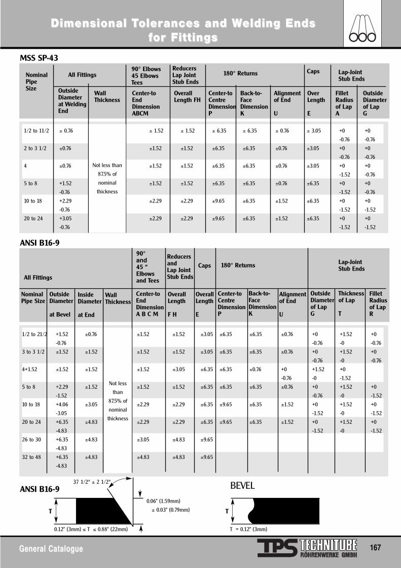
Dimensional TDimensional Tolerolerances and Wances and Welding Endselding Endsffor For Fittingsittings
General CatalogueGeneral Catalogue 167
1/2 to 11/2 ± 0.76 ± 1.52 ± 1.52 ± 6.35 ± 6.35 ± 0.76 ± 3.05 +0 +0
-0.76 -0.76
2 to 3 1/2 ±0.76 ±1.52 ±1.52 ±6.35 ±6.35 ±0.76 ±3.05 +0 +0
-0.76 -0.76
4 ±0.76 ±1.52 ±1.52 ±6.35 ±6.35 ±0.76 ±3.05 +0 +0
-1.52 -0.76
5 to 8 +1.52 ±1.52 ±1.52 ±6.35 ±6.35 ±0.76 ±6.35 +0 +0
-0.76 -1.52 -0.76
10 to 18 +2.29 ±2.29 ±2.29 ±9.65 ±6.35 ±1.52 ±6.35 +0 +0
-0.76 -1.52 -1.52
20 to 24 +3.05 ±2.29 ±2.29 ±9.65 ±6.35 ±1.52 ±6.35 +0 +0
-0.76 -1.52 -1.52
MSS SP-43
ANSI B16-9
ANSI B16-9
All FittingsNominalPipeSize Outside
Diameterat WeldingEnd
WallThickness
Center-toEndDimensionABCM
OverallLength FH
Center-toCentreDimensionP
Back-to-FaceDimensionK
Alignmentof End
U
OverLength
E
FilletRadiusof Lap A
OutsideDiameterof Lap G
Caps Lap-JointStub Ends
90° Elbows45 ElbowsTees
ReducersLap JointStub Ends
180° Returns
Not less than
87.5% of
nominal
thickness
1/2 to 21/2 +1.52 ±0.76 ±1.52 ±1.52 ±3.05 ±6.35 ±6.35 ±0.76 +0 +1.52 +0
-0.76 -0.76 -0 -0.76
3 to 3 1/2 ±1.52 ±1.52 ±1.52 ±1.52 ±3.05 ±6.35 ±6.35 ±0.76 +0 +1.52 +0
-0.76 -0 -0.76
4+1.52 ±1.52 ±1.52 ±1.52 ±3.05 ±6.35 ±6.35 ±0.76 +0 +1.52 +0
-0.76 -0 -1.52
5 to 8 +2.29 ±1.52 ±1.52 ±1.52 ±6.35 ±6.35 ±6.35 ±0.76 +0 +1.52 +0
-1.52 -0.76 -0 -1.52
10 to 18 +4.06 ±3.05 ±2.29 ±2.29 ±6.35 ±9.65 ±6.35 ±1.52 +0 +1.52 +0
-3.05 -1.52 -0 -1.52
20 to 24 +6.35 ±4.83 ±2.29 ±2.29 ±6.35 ±9.65 ±6.35 ±1.52 +0 +1.52 +0
-4.83 -1.52 -0 -1.52
26 to 30 +6.35 ±4.83 ±3.05 ±4.83 ±9.65
-4.83
32 to 48 +6.35 ±4.83 ±4.83 ±4.83 ±9.65
-4.83
All Fittings
NominalPipe Size
OutsideDiameter
at Bevel
InsideDiameter
at End
WallThickness
Center-toEndDimensionA B C M
OverallLength
F H
OverallLength
E
Center-toCentreDimensionP
Back-to-FaceDimensionK
Alignmentof End
U
FilletRadiusof Lap R
OutsideDiameterof Lap G
Thicknessof Lap
T
Lap-JointStub Ends
90°and45 “Elbowsand Tees
Reducersand Lap JointStub Ends
Caps 180° Returns
Not less
than
87.5% of
nominal
thickness
0.12” (3mm) ≤ T ≤ 0.88” (22mm) T = 0.12” (3mm)
T
0.06” (1.59mm)
± 0.03” (0.79mm)
37 1/2° ± 2 1/2° BEVEL
T
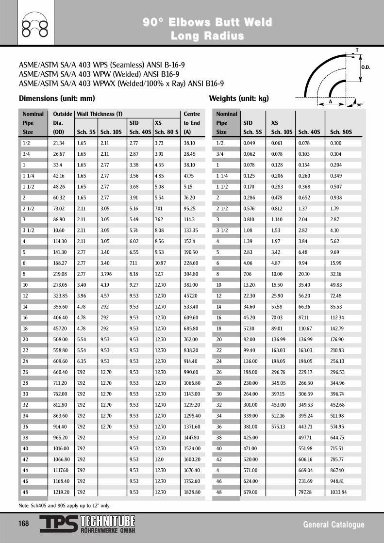
Note: Sch40S and 80S apply up to 12" only
90° Elbo90° Elbowws Butt Ws Butt WeldeldLong RLong Radiusadius
168 General CatalogueGeneral Catalogue
ASME/ASTM SA/A 403 WPS (Seamless) ANSI B-16-9ASME/ASTM SA/A 403 WPW (Welded) ANSI B16-9ASME/ASTM SA/A 403 WPWX (Welded/100% x Ray) ANSI B16-9
Dimensions (unit: mm) Weights (unit: kg)
Nominal Outside Wall Thickness (T) Centre Nominal
Pipe Dia. STD XS to End Pipe STD XS
Size (OD) Sch. 5S Sch. 10S Sch. 40S Sch. 80 S (A) Size Sch. 5S Sch. 10S Sch. 40S Sch. 80S
1/2 21.34 1.65 2.11 2.77 3.73 38.10 1/2 0.049 0.061 0.078 0.100
3/4 26.67 1.65 2.11 2.87 3.91 28.45 3/4 0.062 0.078 0.103 0.104
1 33.4 1.65 2.77 3.38 4.55 38.10 1 0.078 0.128 0.154 0.204
1 1/4 42.16 1.65 2.77 3.56 4.85 47.75 1 1/4 0.125 0.206 0.260 0.349
1 1/2 48.26 1.65 2.77 3.68 5.08 5.15 1 1/2 0.170 0.283 0.368 0.507
2 60.32 1.65 2.77 3.91 5.54 76.20 2 0.286 0.478 0.652 0.938
2 1/2 73.02 2.11 3.05 5.16 7.01 95.25 2 1/2 0.576 0.812 1.37 1.79
3 88.90 2.11 3.05 5.49 7.62 114.3 3 0.810 1.140 2.04 2.87
3 1/2 10.60 2.11 3.05 5.74 8.08 133.35 3 1/2 1.08 1.53 2.82 4.10
4 114.30 2.11 3.05 6.02 8.56 152.4 4 1.39 1.97 3.84 5.62
5 141.30 2.77 3.40 6.55 9.53 190.50 5 2.83 3.42 6.48 9.69
6 168.27 2.77 3.40 7.11 10.97 228.60 6 4.06 4.87 9.94 15.99
8 219.08 2.77 3.796 8.18 12.7 304.80 8 7.06 10.00 20.10 32.16
10 273.05 3.40 4.19 9.27 12.70 381.00 10 13.20 15.50 35.40 49.83
12 323.85 3.96 4.57 9.53 12.70 457.20 12 22.30 25.90 56.20 72.48
14 355.60 4.78 7.92 9.53 12.70 533.40 14 34.60 57.58 66.36 85.53
16 406.40 4.78 7.92 9.53 12.70 609.60 16 45.20 70.03 87.11 112.34
18 457.20 4.78 7.92 9.53 12.70 685.80 18 57.30 89.01 110.67 142.79
20 508.00 5.54 9.53 9.53 12.70 762.00 20 82.00 136.99 136.99 176.90
22 558.80 5.54 9.53 9.53 12.70 838.20 22 99.40 163.03 163.03 210.83
24 609.60 6.35 9.53 9.53 12.70 914.40 24 136.00 198.05 198.05 256.13
26 660.40 7.92 12.70 9.53 12.70 990.60 26 198.00 296.76 229.17 296.53
28 711.20 7.92 12.70 9.53 12.70 1066.80 28 230.00 345.05 266.50 344.96
30 762.00 7.92 12.70 9.53 12.70 1143.00 30 264.00 397.15 306.59 396.74
32 812.80 7.92 12.70 9.53 12.70 1219.20 32 301.00 453.00 349.53 452.68
34 863.60 7.92 12.70 9.53 12.70 1295.40 34 339.00 512.16 395.24 511.98
36 914.40 7.92 12.70 9.53 12.70 1371.60 36 381.00 575.13 443.71 574.95
38 965.20 7.92 9.53 12.70 1447.80 38 425.00 497.71 644.75
40 1016.00 7.92 9.53 12.70 1524.00 40 471.00 551.98 715.51
42 1066.80 7.92 9.53 12.0 1600.20 42 520.00 606.16 785.77
44 1117.60 7.92 9.53 12.70 1676.40 4 571.00 669.04 867.40
46 1168.40 7.92 9.53 12.70 1752.60 46 624.00 7.31.69 948.81
48 1219.20 7.92 9.53 12.70 1828.80 48 679.00 797.28 1033.84
A
O.D.
T
90°
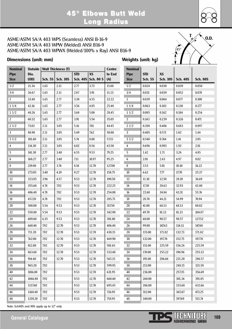
Note: Sch40S and 80S apply up to 12" only
45° Elbo45° Elbowws Butt Ws Butt WeldeldLong RLong Radiusadius
General CatalogueGeneral Catalogue 169
ASME/ASTM SA/A 403 WPS (Seamless) ANSI B-16-9ASME/ASTM SA/A 403 WPW (Welded) ANSI B16-9ASME/ASTM SA/A 403 WPWX (Welded/100% x Ray) ANSI B16-9
Dimensions (unit: mm) Weights (unit: kg)
Nominal Outside Wall Thickness (T) Centre NominalPipe Dia. STD XS to End Pipe STD XSSize (OD) Sch. 5S Sch. 10S Sch. 40S Sch. 80 S (A) Size Sch. 5S Sch. 10S Sch. 40S Sch. 80S
1/2 21.34 1.65 2.11 2.77 3.73 15.88 1/2 0.024 0.030 0.039 0.050
3/4 26.67 1.65 2.11 2.87 3.91 11.13 3/4 0.031 0.039 0.052 0.078
1 33.40 1.65 2.77 3.38 4.55 22.22 1 0.039 0.064 0.077 0.100
1 1/4 42.16 1.65 2.77 3.56 4.85 25.40 1 1/4 0.063 0.103 0.130 0.177
1 1/2 48.26 1.65 2.77 3.68 5.08 28.45 1 1/2 0.085 0.142 0.184 0.254
2 60.32 1.65 2.77 3.91 5.54 35.05 2 0.143 0.239 0.326 0.471
2 1/2 73.02 2.11 3.05 5.16 7.01 44.45 2 1/2 0.288 0.406 0.683 0.897
3 88.90 2.11 3.05 5.49 7.62 50.80 3 0.405 0.571 1.02 1.44
3 1/2 101.60 2.11 3.05 5.74 8.08 57.15 3 1/2 0.540 0.764 1.41 2.05
4 114.30 2.11 3.05 6.02 8.56 63.50 4 0.696 0.985 1.92 2.81
5 141.30 2.77 3.40 6.55 9.53 79.25 5 1.42 1.71 3.24 4.85
6 168.27 2.77 3.40 7.11 10.97 95.25 6 2.01 2.43 4.97 8.02
8 219.08 2.77 3.76 8.18 12.70 127.00 8 3.53 5.01 10.10 16.22
10 273.05 3.40 4.19 9.27 12.70 158.75 10 6.62 7.77 17.70 25.37
12 323.85 3.96 4.57 9.53 12.70 190.50 12 11.10 12.50 28.10 36.69
14 355.60 4.78 7.92 9.53 12.70 222.25 14 17.30 28.63 32.93 42.40
16 406.40 4.78 7.92 9.53 12.70 254.00 16 22.60 34.84 43.31 55.76
18 457.20 4.78 7.92 9.53 12.70 285.75 18 28.70 44.21 54.99 70.94
20 508.00 5.54 9.53 9.53 12.70 317.50 20 41.00 68.13 68.13 88.02
22 558.80 5.54 9.53 9.53 12.70 342.90 22 49.70 81.13 81.13 104.87
24 609.60 6.35 9.53 9.53 12.70 381.00 24 68.00 98.57 98.57 127.52
26 660.40 7.92 12.70 9.53 12.70 406.40 26 99.00 147.63 114.11 147.68
28 711.20 7.92 12.70 9.53 12.70 438.15 28 115.00 171.82 132.73 171.82
30 762.00 7.92 12.70 9.53 12.70 469.90 30 132.00 197.78 152.75 197.78
32 812.80 7.92 12.70 9.53 12.70 501.65 32 151.00 225.59 156.24 225.59
34 863.60 7.92 12.70 9.53 12.70 533.40 34 170.00 255.22 196.96 255.13
36 914.40 7.92 12.70 9.53 12.70 565.15 36 191.00 286.66 221.20 286.57
38 965.20 7.92 9.53 12.70 599.95 38 213.00 248.15 321.58
40 1016.00 7.92 9.53 12.70 631.95 40 236.00 257.35 356.69
42 1066.80 7.92 9.53 12.70 660.40 42 260.00 301.34 391.85
44 1117.60 7.92 9.53 12.70 695.45 44 286.00 333.68 432.66
46 1168.40 7.92 9.53 12.70 726.95 46 312.00 365.07 473.25
48 1219.20 7.92 9.53 12.70 758.95 48 340.00 397.69 515.74
O.D.T
45°
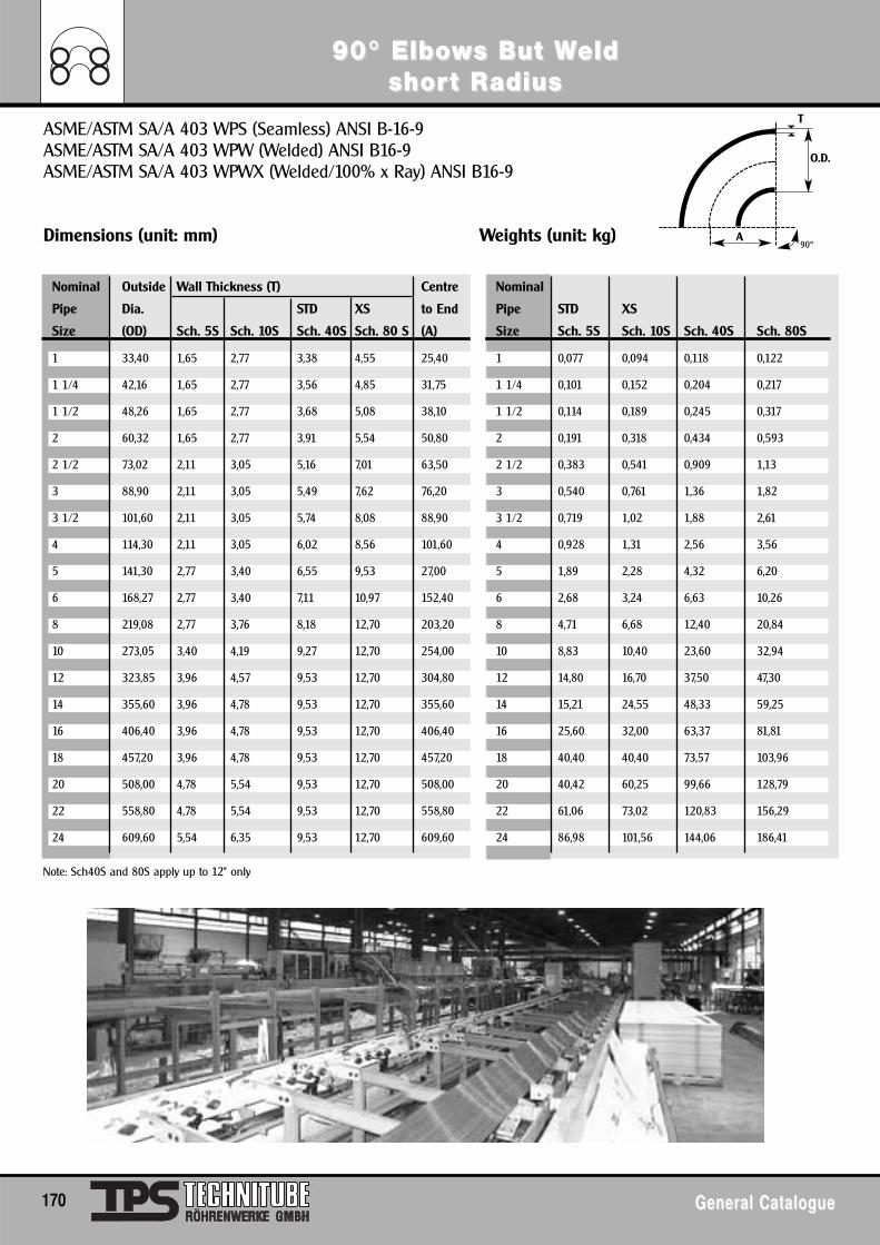
90° Elbo90° Elbowws But Ws But Weldeldshorshort Rt Radiusadius
170 General CatalogueGeneral Catalogue
Note: Sch40S and 80S apply up to 12" only
ASME/ASTM SA/A 403 WPS (Seamless) ANSI B-16-9ASME/ASTM SA/A 403 WPW (Welded) ANSI B16-9ASME/ASTM SA/A 403 WPWX (Welded/100% x Ray) ANSI B16-9
Dimensions (unit: mm) Weights (unit: kg)
Nominal Outside Wall Thickness (T) Centre Nominal
Pipe Dia. STD XS to End Pipe STD XS
Size (OD) Sch. 5S Sch. 10S Sch. 40S Sch. 80 S (A) Size Sch. 5S Sch. 10S Sch. 40S Sch. 80S
1 33,40 1,65 2,77 3,38 4,55 25,40 1 0,077 0,094 0,118 0,122
1 1/4 42,16 1,65 2,77 3,56 4,85 31,75 1 1/4 0,101 0,152 0,204 0,217
1 1/2 48,26 1,65 2,77 3,68 5,08 38,10 1 1/2 0,114 0,189 0,245 0,317
2 60,32 1,65 2,77 3,91 5,54 50,80 2 0,191 0,318 0,434 0,593
2 1/2 73,02 2,11 3,05 5,16 7,01 63,50 2 1/2 0,383 0,541 0,909 1,13
3 88,90 2,11 3,05 5,49 7,62 76,20 3 0,540 0,761 1,36 1,82
3 1/2 101,60 2,11 3,05 5,74 8,08 88,90 3 1/2 0,719 1,02 1,88 2,61
4 114,30 2,11 3,05 6,02 8,56 101,60 4 0,928 1,31 2,56 3,56
5 141,30 2,77 3,40 6,55 9,53 27,00 5 1,89 2,28 4,32 6,20
6 168,27 2,77 3,40 7,11 10,97 152,40 6 2,68 3,24 6,63 10,26
8 219,08 2,77 3,76 8,18 12,70 203,20 8 4,71 6,68 12,40 20,84
10 273,05 3,40 4,19 9,27 12,70 254,00 10 8,83 10,40 23,60 32,94
12 323,85 3,96 4,57 9,53 12,70 304,80 12 14,80 16,70 37,50 47,30
14 355,60 3,96 4,78 9,53 12,70 355,60 14 15,21 24,55 48,33 59,25
16 406,40 3,96 4,78 9,53 12,70 406,40 16 25,60 32,00 63,37 81,81
18 457,20 3,96 4,78 9,53 12,70 457,20 18 40,40 40,40 73,57 103,96
20 508,00 4,78 5,54 9,53 12,70 508,00 20 40,42 60,25 99,66 128,79
22 558,80 4,78 5,54 9,53 12,70 558,80 22 61,06 73,02 120,83 156,29
24 609,60 5,54 6,35 9,53 12,70 609,60 24 86,98 101,56 144,06 186,41
A
O.D.
T
90°
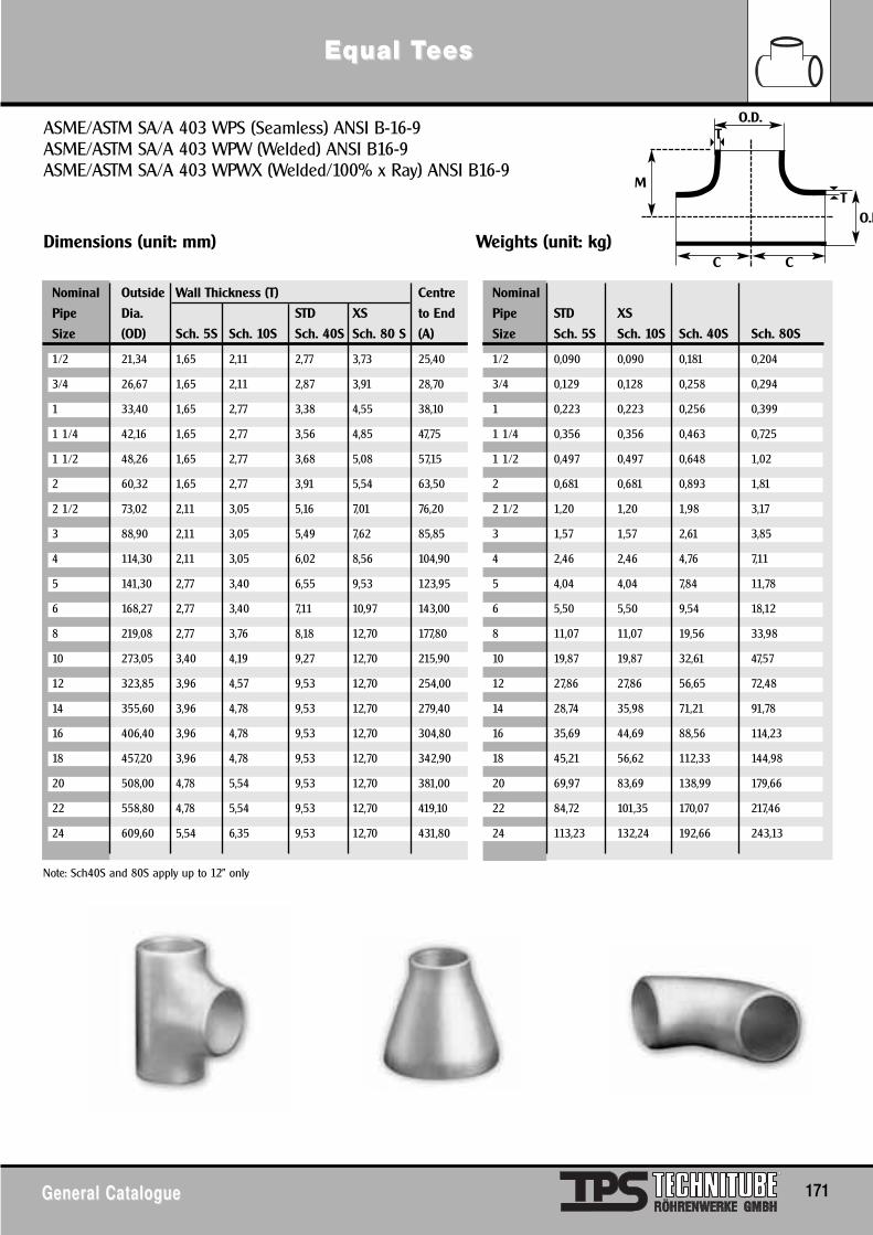
EqEqual Tual Teesees
General CatalogueGeneral Catalogue 171
Note: Sch40S and 80S apply up to 12" only
ASME/ASTM SA/A 403 WPS (Seamless) ANSI B-16-9ASME/ASTM SA/A 403 WPW (Welded) ANSI B16-9ASME/ASTM SA/A 403 WPWX (Welded/100% x Ray) ANSI B16-9
Dimensions (unit: mm) Weights (unit: kg)
Nominal Outside Wall Thickness (T) Centre Nominal
Pipe Dia. STD XS to End Pipe STD XS
Size (OD) Sch. 5S Sch. 10S Sch. 40S Sch. 80 S (A) Size Sch. 5S Sch. 10S Sch. 40S Sch. 80S
1/2 21,34 1,65 2,11 2,77 3,73 25,40 1/2 0,090 0,090 0,181 0,204
3/4 26,67 1,65 2,11 2,87 3,91 28,70 3/4 0,129 0,128 0,258 0,294
1 33,40 1,65 2,77 3,38 4,55 38,10 1 0,223 0,223 0,256 0,399
1 1/4 42,16 1,65 2,77 3,56 4,85 47,75 1 1/4 0,356 0,356 0,463 0,725
1 1/2 48,26 1,65 2,77 3,68 5,08 57,15 1 1/2 0,497 0,497 0,648 1,02
2 60,32 1,65 2,77 3,91 5,54 63,50 2 0,681 0,681 0,893 1,81
2 1/2 73,02 2,11 3,05 5,16 7,01 76,20 2 1/2 1,20 1,20 1,98 3,17
3 88,90 2,11 3,05 5,49 7,62 85,85 3 1,57 1,57 2,61 3,85
4 114,30 2,11 3,05 6,02 8,56 104,90 4 2,46 2,46 4,76 7,11
5 141,30 2,77 3,40 6,55 9,53 123,95 5 4,04 4,04 7,84 11,78
6 168,27 2,77 3,40 7,11 10,97 143,00 6 5,50 5,50 9,54 18,12
8 219,08 2,77 3,76 8,18 12,70 177,80 8 11,07 11,07 19,56 33,98
10 273,05 3,40 4,19 9,27 12,70 215,90 10 19,87 19,87 32,61 47,57
12 323,85 3,96 4,57 9,53 12,70 254,00 12 27,86 27,86 56,65 72,48
14 355,60 3,96 4,78 9,53 12,70 279,40 14 28,74 35,98 71,21 91,78
16 406,40 3,96 4,78 9,53 12,70 304,80 16 35,69 44,69 88,56 114,23
18 457,20 3,96 4,78 9,53 12,70 342,90 18 45,21 56,62 112,33 144,98
20 508,00 4,78 5,54 9,53 12,70 381,00 20 69,97 83,69 138,99 179,66
22 558,80 4,78 5,54 9,53 12,70 419,10 22 84,72 101,35 170,07 217,46
24 609,60 5,54 6,35 9,53 12,70 431,80 24 113,23 132,24 192,66 243,13
O.D.
O.D
CC
MT
T
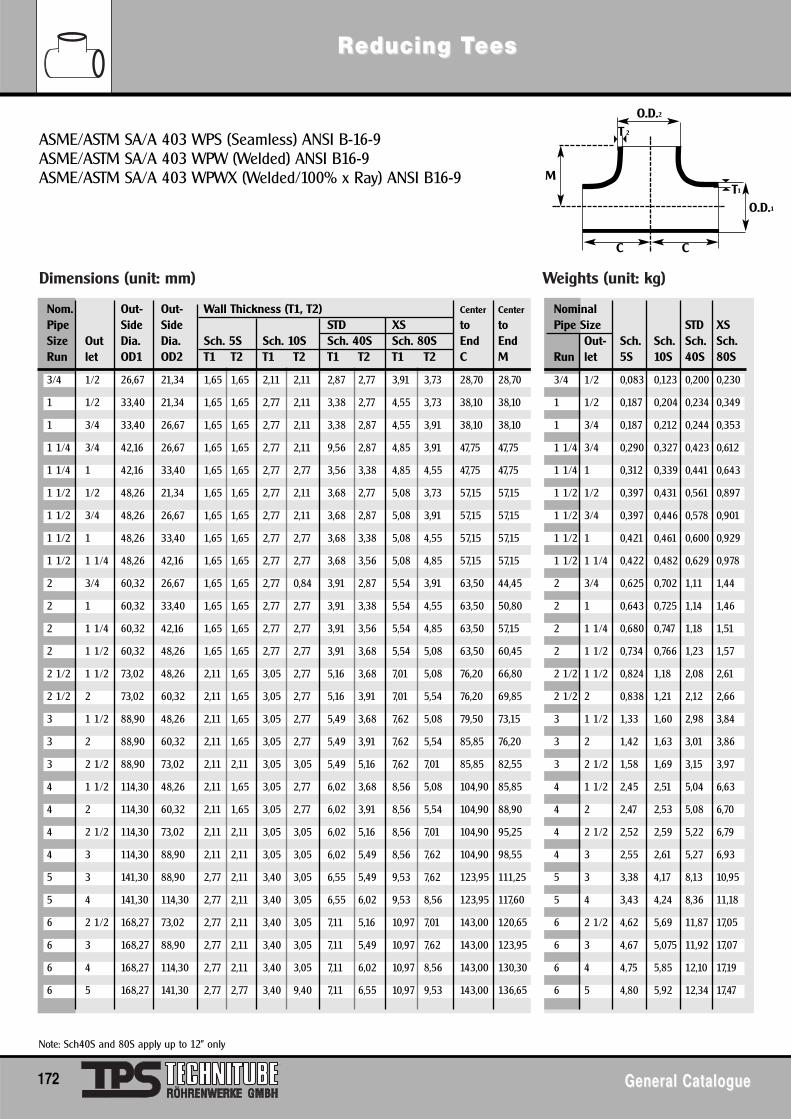
Dimensions (unit: mm) Weights (unit: kg)
Note: Sch40S and 80S apply up to 12" only
RReducing Teducing Teesees
172 General CatalogueGeneral Catalogue
ASME/ASTM SA/A 403 WPS (Seamless) ANSI B-16-9ASME/ASTM SA/A 403 WPW (Welded) ANSI B16-9ASME/ASTM SA/A 403 WPWX (Welded/100% x Ray) ANSI B16-9
Nom. Out- Out- Wall Thickness (T1, T2) Center Center NominalPipe Side Side STD XS to to Pipe Size STD XSSize Out Dia. Dia. Sch. 5S Sch. 10S Sch. 40S Sch. 80S End End Out- Sch. Sch. Sch. Sch.Run let OD1 OD2 T1 T2 T1 T2 T1 T2 T1 T2 C M Run let 5S 10S 40S 80S
3/4 1/2 26,67 21,34 1,65 1,65 2,11 2,11 2,87 2,77 3,91 3,73 28,70 28,70 3/4 1/2 0,083 0,123 0,200 0,230
1 1/2 33,40 21,34 1,65 1,65 2,77 2,11 3,38 2,77 4,55 3,73 38,10 38,10 1 1/2 0,187 0,204 0,234 0,349
1 3/4 33,40 26,67 1,65 1,65 2,77 2,11 3,38 2,87 4,55 3,91 38,10 38,10 1 3/4 0,187 0,212 0,244 0,353
1 1/4 3/4 42,16 26,67 1,65 1,65 2,77 2,11 9,56 2,87 4,85 3,91 47,75 47,75 1 1/4 3/4 0,290 0,327 0,423 0,612
1 1/4 1 42,16 33,40 1,65 1,65 2,77 2,77 3,56 3,38 4,85 4,55 47,75 47,75 1 1/4 1 0,312 0,339 0,441 0,643
1 1/2 1/2 48,26 21,34 1,65 1,65 2,77 2,11 3,68 2,77 5,08 3,73 57,15 57,15 1 1/2 1/2 0,397 0,431 0,561 0,897
1 1/2 3/4 48,26 26,67 1,65 1,65 2,77 2,11 3,68 2,87 5,08 3,91 57,15 57,15 1 1/2 3/4 0,397 0,446 0,578 0,901
1 1/2 1 48,26 33,40 1,65 1,65 2,77 2,77 3,68 3,38 5,08 4,55 57,15 57,15 1 1/2 1 0,421 0,461 0,600 0,929
1 1/2 1 1/4 48,26 42,16 1,65 1,65 2,77 2,77 3,68 3,56 5,08 4,85 57,15 57,15 1 1/2 1 1/4 0,422 0,482 0,629 0,978
2 3/4 60,32 26,67 1,65 1,65 2,77 0,84 3,91 2,87 5,54 3,91 63,50 44,45 2 3/4 0,625 0,702 1,11 1,44
2 1 60,32 33,40 1,65 1,65 2,77 2,77 3,91 3,38 5,54 4,55 63,50 50,80 2 1 0,643 0,725 1,14 1,46
2 1 1/4 60,32 42,16 1,65 1,65 2,77 2,77 3,91 3,56 5,54 4,85 63,50 57,15 2 1 1/4 0,680 0,747 1,18 1,51
2 1 1/2 60,32 48,26 1,65 1,65 2,77 2,77 3,91 3,68 5,54 5,08 63,50 60,45 2 1 1/2 0,734 0,766 1,23 1,57
2 1/2 1 1/2 73,02 48,26 2,11 1,65 3,05 2,77 5,16 3,68 7,01 5,08 76,20 66,80 2 1/2 1 1/2 0,824 1,18 2,08 2,61
2 1/2 2 73,02 60,32 2,11 1,65 3,05 2,77 5,16 3,91 7,01 5,54 76,20 69,85 2 1/2 2 0,838 1,21 2,12 2,66
3 1 1/2 88,90 48,26 2,11 1,65 3,05 2,77 5,49 3,68 7,62 5,08 79,50 73,15 3 1 1/2 1,33 1,60 2,98 3,84
3 2 88,90 60,32 2,11 1,65 3,05 2,77 5,49 3,91 7,62 5,54 85,85 76,20 3 2 1,42 1,63 3,01 3,86
3 2 1/2 88,90 73,02 2,11 2,11 3,05 3,05 5,49 5,16 7,62 7,01 85,85 82,55 3 2 1/2 1,58 1,69 3,15 3,97
4 1 1/2 114,30 48,26 2,11 1,65 3,05 2,77 6,02 3,68 8,56 5,08 104,90 85,85 4 1 1/2 2,45 2,51 5,04 6,63
4 2 114,30 60,32 2,11 1,65 3,05 2,77 6,02 3,91 8,56 5,54 104,90 88,90 4 2 2,47 2,53 5,08 6,70
4 2 1/2 114,30 73,02 2,11 2,11 3,05 3,05 6,02 5,16 8,56 7,01 104,90 95,25 4 2 1/2 2,52 2,59 5,22 6,79
4 3 114,30 88,90 2,11 2,11 3,05 3,05 6,02 5,49 8,56 7,62 104,90 98,55 4 3 2,55 2,61 5,27 6,93
5 3 141,30 88,90 2,77 2,11 3,40 3,05 6,55 5,49 9,53 7,62 123,95 111,25 5 3 3,38 4,17 8,13 10,95
5 4 141,30 114,30 2,77 2,11 3,40 3,05 6,55 6,02 9,53 8,56 123,95 117,60 5 4 3,43 4,24 8,36 11,18
6 2 1/2 168,27 73,02 2,77 2,11 3,40 3,05 7,11 5,16 10,97 7,01 143,00 120,65 6 2 1/2 4,62 5,69 11,87 17,05
6 3 168,27 88,90 2,77 2,11 3,40 3,05 7,11 5,49 10,97 7,62 143,00 123,95 6 3 4,67 5,075 11,92 17,07
6 4 168,27 114,30 2,77 2,11 3,40 3,05 7,11 6,02 10,97 8,56 143,00 130,30 6 4 4,75 5,85 12,10 17,19
6 5 168,27 141,30 2,77 2,77 3,40 9,40 7,11 6,55 10,97 9,53 143,00 136,65 6 5 4,80 5,92 12,34 17,47
O.D.2
O.D.1
CC
MT1
T 2
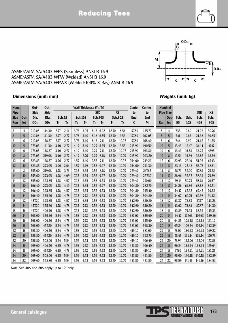
Dimensions (unit: mm) Weights (unit: kg)
Nom. Out- Out- Wall Thickness (T1, T2) Center Center NominalPipe Side Side STD XS to to Pipe Size STD XSSize Out- Dia. Dia. Sch.5S Sch.10S Sch.40S Sch.80S End End Out- Sch. Sch. Sch. Sch.Run let OD1 OD2 T1 T2 T1 T2 T1 T2 T1 T2 C M Run let 5S 10S 40S 80S
8 4 219.08 114.30 2.77 2.11 3.76 3.05 8.18 6.02 12.70 8.56 177.80 155.70 8 4 7.35 9.80 21.26 30.768 5 219.08 141.30 2.77 2.77 3.76 3.40 8.18 6.55 12.70 9.53 177.80 162.05 8 5 7.41 9.83 21.36 30.858 6 219.08 168.27 2.77 2.77 3.76 3.40 8.18 7.11 12.70 10.97 177.80 168.40 8 6 7.44 9.90 21.62 31.2510 5 273.05 141.30 3.40 2.77 4.19 3.40 9.27 6.55 12.70 9.53 215.90 190.50 10 5 13.43 16.47 36.14 47.4710 6 273.05 168.27 3.40 2.77 4.19 3.40 9.27 7.11 12.70 10.97 215.90 193.80 10 6 13.49 16.58 36.27 47.9510 8 273.05 219.08 3.40 2.77 4.19 3.76 9.27 8.18 12.70 12.70 215.90 203.20 10 8 13.54 16.69 36.85 48.3912 6 323.85 168.27 3.96 2.77 4.57 3.40 9.53 7.11 12.70 10.97 254.00 219.20 12 6 22.93 25.10 51.96 67.4312 10 323.85 273.05 3.96 2.64 4.57 4.19 9.53 9.27 12.70 12.70 254.00 241.30 12 10 23.13 25.48 53.72 68.8114 8 355.60 219.08 4.78 3.76 7.92 6.35 9.53 8.18 12.70 12.70 279.40 247.65 14 8 28.79 52.00 57.88 75.2214 10 355.60 273.05 4.78 4.09 7.92 6.35 9.53 9.27 12.70 12.70 279.40 257.30 14 10 28.96 52.37 58.34 75.8914 12 355.60 323.85 4.78 4.57 7.92 6.35 9.53 9.53 12.70 12.70 279.40 270.00 14 12 29.14 52.73 58.81 76.5716 10 406.40 273.05 4.78 4.19 7.92 6.35 9.53 9.27 12.70 12.70 304.80 282.70 16 10 34.26 61.89 68.88 89.5116 12 406.40 323.85 4.78 4.57 7.92 6.35 9.53 9.53 12.70 12.70 304.80 295.40 16 12 34.47 62.32 69.43 90.3216 14 406.40 335.60 4.78 4.78 7.92 7.92 9.53 9.53 12.70 12.70 304.80 304.80 16 14 34.67 62.76 69.98 91.1218 12 457.20 323.85 4.78 4.57 7.92 6.35 9.53 9.53 12.70 12.70 342.90 320.80 18 12 43.37 78.33 87.17 113.2818 14 457.20 355.60 4.78 4.78 7.92 7.92 9.53 9.53 12.70 12.70 342.90 330.20 18 14 43.62 78.88 87.87 114.3018 16 457.20 406.40 4.78 4.78 7.92 7.92 9.53 9.53 12.70 12.70 342.90 330.20 18 16 43.89 79.43 88.57 115.3320 14 508.00 355.60 5.54 4.78 9.53 7.92 9.53 9.53 12.70 12.70 381.00 355.60 20 14 64.47 107.63 107.63 139.8620 16 508.00 406.40 5.54 4.78 9.53 7.92 9.53 9.53 12.70 12.70 381.00 355.60 20 16 64.85 108.38 108.38 141.1220 18 508.00 457.20 5.54 4.78 9.53 7.92 9.53 9.53 12.70 12.70 381.00 368.30 20 18 65.24 109.24 109.14 142.3922 16 558.80 406.40 5.54 4.78 9.53 7.92 9.53 9.53 12.70 12.70 419.10 381.00 22 16 78.00 130.23 130.23 169.2222 18 558.80 457.20 5.54 4.78 9.53 7.92 9.53 9.53 12.70 12.70 419.10 393.70 22 18 78.47 131.14 131.14 170.7422 20 558.80 508.00 5.54 5.54 9.53 9.53 9.53 9.53 12.70 12.70 419.10 406.40 22 20 78.94 132.06 132.06 172.8824 16 609.60 406.40 6.35 4.78 9.53 7.92 9.53 9.53 12.70 12.70 431.80 406.40 24 16 96.84 138.24 138.24 179.6424 18 609.60 457.20 6.35 4.78 9.53 7.92 9.53 9.53 12.70 12.70 431.80 419.10 24 18 97.69 139.21 139.21 181.2524 20 609.60 508.00 6.35 5.54 9.53 9.53 9.53 9.53 12.70 12.70 431.80 431.80 24 20 98.00 140.18 140.18 182.8924 22 609.60 558.80 6.35 5.54 9.53 9.53 9.53 9.53 12.70 12.70 431.80 431.80 24 22 98.59 141.16 141.16 184.53
RReducing Teducing Teesees
General catalogueGeneral catalogue 173
ASME/ASTM SA/A403 WPS (Seamless) ANSI B 16.9ASME/ASTM SA/A403 WPW (Welded) ANSI B 16.9ASME/ASTM SA/A403 WPWX (Welded/100% X Ray) ANSI B 16.9
Note: Sch 40S and 80S apply up to 12" only
O.D.2
O.D.1
CC
MT1
T 2
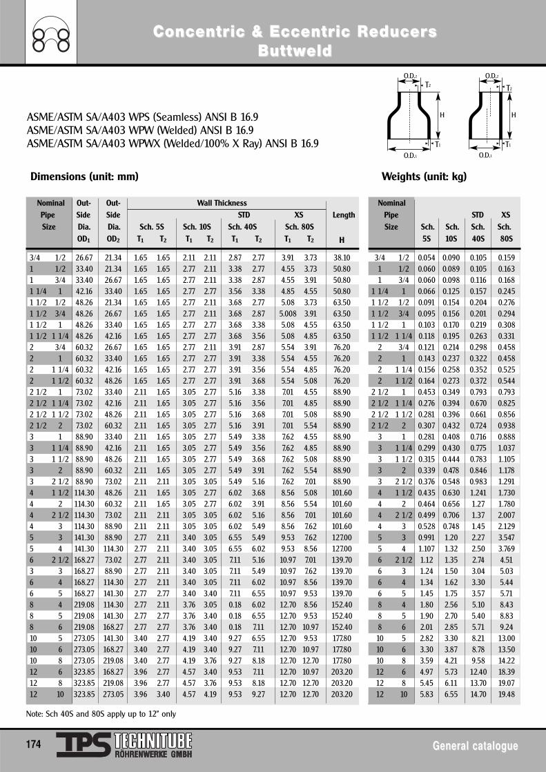
ConcentrConcentric & Eccentric & Eccentric Ric ReducereducerssButtwButtweldeld
174 General catalogueGeneral catalogue
ASME/ASTM SA/A403 WPS (Seamless) ANSI B 16.9ASME/ASTM SA/A403 WPW (Welded) ANSI B 16.9ASME/ASTM SA/A403 WPWX (Welded/100% X Ray) ANSI B 16.9
Dimensions (unit: mm) Weights (unit: kg)
Nominal Out- Out- Wall Thickness NominalPipe Side Side STD XS Length Pipe STD XSSize Dia. Dia. Sch. 5S Sch. 10S Sch. 40S Sch. 80S Size Sch. Sch. Sch. Sch.
OD1 OD2 T1 T2 T1 T2 T1 T2 T1 T2 H 5S 10S 40S 80S
3/4 1/2 26.67 21.34 1.65 1.65 2.11 2.11 2.87 2.77 3.91 3.73 38.10 3/4 1/2 0.054 0.090 0.105 0.1591 1/2 33.40 21.34 1.65 1.65 2.77 2.11 3.38 2.77 4.55 3.73 50.80 1 1/2 0.060 0.089 0.105 0.1631 3/4 33.40 26.67 1.65 1.65 2.77 2.11 3.38 2.87 4.55 3.91 50.80 1 3/4 0.060 0.098 0.116 0.1681 1/4 1 42.16 33.40 1.65 1.65 2.77 2.77 3.56 3.38 4.85 4.55 50.80 1 1/4 1 0.066 0.125 0.157 0.2451 1/2 1/2 48.26 21.34 1.65 1.65 2.77 2.11 3.68 2.77 5.08 3.73 63.50 1 1/2 1/2 0.091 0.154 0.204 0.2761 1/2 3/4 48.26 26.67 1.65 1.65 2.77 2.11 3.68 2.87 5.008 3.91 63.50 1 1/2 3/4 0.095 0.156 0.201 0.2941 1/2 1 48.26 33.40 1.65 1.65 2.77 2.77 3.68 3.38 5.08 4.55 63.50 1 1/2 1 0.103 0.170 0.219 0.3081 1/2 1 1/4 48.26 42.16 1.65 1.65 2.77 2.77 3.68 3.56 5.08 4.85 63.50 1 1/2 1 1/4 0.118 0.195 0.263 0.3312 3/4 60.32 26.67 1.65 1.65 2.77 2.11 3.91 2.87 5.54 3.91 76.20 2 3/4 0.121 0.214 0.298 0.4582 1 60.32 33.40 1.65 1.65 2.77 2.77 3.91 3.38 5.54 4.55 76.20 2 1 0.143 0.237 0.322 0.4582 1 1/4 60.32 42.16 1.65 1.65 2.77 2.77 3.91 3.56 5.54 4.85 76.20 2 1 1/4 0.156 0.258 0.352 0.5252 1 1/2 60.32 48.26 1.65 1.65 2.77 2.77 3.91 3.68 5.54 5.08 76.20 2 1 1/2 0.164 0.273 0.372 0.5442 1/2 1 73.02 33.40 2.11 1.65 3.05 2.77 5.16 3.38 7.01 4.55 88.90 2 1/2 1 0.453 0.349 0.793 0.7932 1/2 1 1/4 73.02 42.16 2.11 1.65 3.05 2.77 5.16 3.56 7.01 4.85 88.90 2 1/2 1 1/4 0.276 0.394 0.670 0.8252 1/2 1 1/2 73.02 48.26 2.11 1.65 3.05 2.77 5.16 3.68 7.01 5.08 88.90 2 1/2 1 1/2 0.281 0.396 0.661 0.8562 1/2 2 73.02 60.32 2.11 1.65 3.05 2.77 5.16 3.91 7.01 5.54 88.90 2 1/2 2 0.307 0.432 0.724 0.9383 1 88.90 33.40 2.11 1.65 3.05 2.77 5.49 3.38 7.62 4.55 88.90 3 1 0.281 0.408 0.716 0.8883 1 1/4 88.90 42.16 2.11 1.65 3.05 2.77 5.49 3.56 7.62 4.85 88.90 3 1 1/4 0.299 0.430 0.775 1.0373 1 1/2 88.90 48.26 2.11 1.65 3.05 2.77 5.49 3.68 7.62 5.08 88.90 3 1 1/2 0.315 0.444 0.783 1.1053 2 88.90 60.32 2.11 1.65 3.05 2.77 5.49 3.91 7.62 5.54 88.90 3 2 0.339 0.478 0.846 1.1783 2 1/2 88.90 73.02 2.11 2.11 3.05 3.05 5.49 5.16 7.62 7.01 88.90 3 2 1/2 0.376 0.548 0.983 1.2914 1 1/2 114.30 48.26 2.11 1.65 3.05 2.77 6.02 3.68 8.56 5.08 101.60 4 1 1/2 0.435 0.630 1.241 1.7304 2 114.30 60.32 2.11 1.65 3.05 2.77 6.02 3.91 8.56 5.54 101.60 4 2 0.464 0.656 1.27 1.7804 2 1/2 114.30 73.02 2.11 2.11 3.05 3.05 6.02 5.16 8.56 7.01 101.60 4 2 1/2 0.499 0.706 1.37 2.0074 3 114.30 88.90 2.11 2.11 3.05 3.05 6.02 5.49 8.56 7.62 101.60 4 3 0.528 0.748 1.45 2.1295 3 141.30 88.90 2.77 2.11 3.40 3.05 6.55 5.49 9.53 7.62 127.00 5 3 0.991 1.20 2.27 3.5475 4 141.30 114.30 2.77 2.11 3.40 3.05 6.55 6.02 9.53 8.56 127.00 5 4 1.107 1.32 2.50 3.7696 2 1/2 168.27 73.02 2.77 2.11 3.40 3.05 7.11 5.16 10.97 7.01 139.70 6 2 1/2 1.12 1.35 2.74 4.513 3 168.27 88.90 2.77 2.11 3.40 3.05 7.11 5.49 10.97 7.62 139.70 6 3 1.24 1.50 3.04 5.036 4 168.27 114.30 2.77 2.11 3.40 3.05 7.11 6.02 10.97 8.56 139.70 6 4 1.34 1.62 3.30 5.446 5 168.27 141.30 2.77 2.77 3.40 3.40 7.11 6.55 10.97 9.53 139.70 6 5 1.45 1.75 3.57 5.718 4 219.08 114.30 2.77 2.11 3.76 3.05 0.18 6.02 12.70 8.56 152.40 8 4 1.80 2.56 5.10 8.438 5 219.08 141.30 2.77 2.77 3.76 3.40 0.18 6.55 12.70 9.53 152.40 8 5 1.90 2.70 5.40 8.838 6 219.08 168.27 2.77 2.77 3.76 3.40 0.18 7.11 12.70 10.97 152.40 8 6 2.01 2.85 5.71 9.2410 5 273.05 141.30 3.40 2.77 4.19 3.40 9.27 6.55 12.70 9.53 177.80 10 5 2.82 3.30 8.21 13.0010 6 273.05 168.27 3.40 2.77 4.19 3.40 9.27 7.11 12.70 10.97 177.80 10 6 3.30 3.87 8.78 13.5010 8 273.05 219.08 3.40 2.77 4.19 3.76 9.27 8.18 12.70 12.70 177.80 10 8 3.59 4.21 9.58 14.2212 6 323.85 168.27 3.96 2.77 4.57 3.40 9.53 7.11 12.70 10.97 203.20 12 6 4.97 5.73 12.40 18.3912 8 323.85 219.08 3.96 2.77 4.57 3.76 9.53 8.18 12.70 12.70 203.20 12 8 5.45 6.11 13.70 19.0712 10 323.85 273.05 3.96 3.40 4.57 4.19 9.53 9.27 12.70 12.70 203.20 12 10 5.83 6.55 14.70 19.48
Note: Sch 40S and 80S apply up to 12" only
O.D.1
O.D.2 O.D.2T2
T1
T2
O.D.1T1
H H
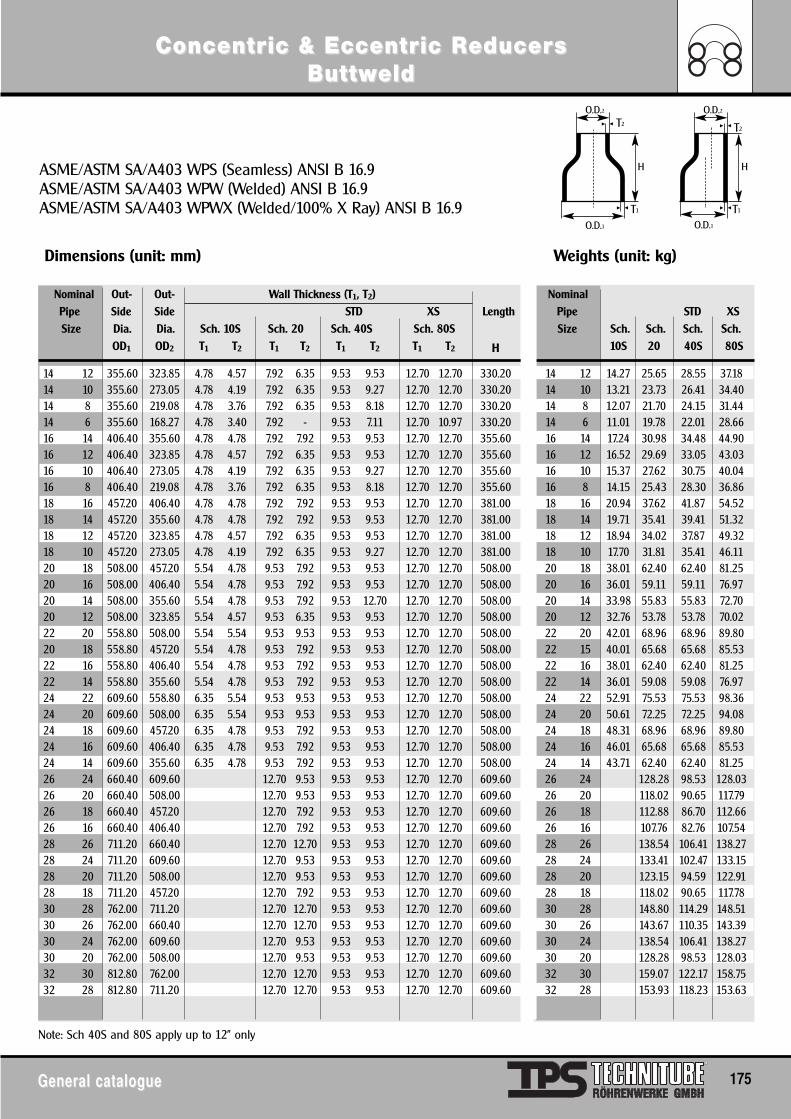
ConcentrConcentric & Eccentric & Eccentric Ric ReducereducerssButtwButtweldeld
General catalogueGeneral catalogue 175
ASME/ASTM SA/A403 WPS (Seamless) ANSI B 16.9ASME/ASTM SA/A403 WPW (Welded) ANSI B 16.9ASME/ASTM SA/A403 WPWX (Welded/100% X Ray) ANSI B 16.9
Dimensions (unit: mm) Weights (unit: kg)
Nominal Out- Out- Wall Thickness (T1, T2) NominalPipe Side Side STD XS Length Pipe STD XSSize Dia. Dia. Sch. 10S Sch. 20 Sch. 40S Sch. 80S Size Sch. Sch. Sch. Sch.
OD1 OD2 T1 T2 T1 T2 T1 T2 T1 T2 H 10S 20 40S 80S
14 12 355.60 323.85 4.78 4.57 7.92 6.35 9.53 9.53 12.70 12.70 330.20 14 12 14.27 25.65 28.55 37.1814 10 355.60 273.05 4.78 4.19 7.92 6.35 9.53 9.27 12.70 12.70 330.20 14 10 13.21 23.73 26.41 34.4014 8 355.60 219.08 4.78 3.76 7.92 6.35 9.53 8.18 12.70 12.70 330.20 14 8 12.07 21.70 24.15 31.4414 6 355.60 168.27 4.78 3.40 7.92 - 9.53 7.11 12.70 10.97 330.20 14 6 11.01 19.78 22.01 28.6616 14 406.40 355.60 4.78 4.78 7.92 7.92 9.53 9.53 12.70 12.70 355.60 16 14 17.24 30.98 34.48 44.9016 12 406.40 323.85 4.78 4.57 7.92 6.35 9.53 9.53 12.70 12.70 355.60 16 12 16.52 29.69 33.05 43.0316 10 406.40 273.05 4.78 4.19 7.92 6.35 9.53 9.27 12.70 12.70 355.60 16 10 15.37 27.62 30.75 40.0416 8 406.40 219.08 4.78 3.76 7.92 6.35 9.53 8.18 12.70 12.70 355.60 16 8 14.15 25.43 28.30 36.8618 16 457.20 406.40 4.78 4.78 7.92 7.92 9.53 9.53 12.70 12.70 381.00 18 16 20.94 37.62 41.87 54.5218 14 457.20 355.60 4.78 4.78 7.92 7.92 9.53 9.53 12.70 12.70 381.00 18 14 19.71 35.41 39.41 51.3218 12 457.20 323.85 4.78 4.57 7.92 6.35 9.53 9.53 12.70 12.70 381.00 18 12 18.94 34.02 37.87 49.3218 10 457.20 273.05 4.78 4.19 7.92 6.35 9.53 9.27 12.70 12.70 381.00 18 10 17.70 31.81 35.41 46.1120 18 508.00 457.20 5.54 4.78 9.53 7.92 9.53 9.53 12.70 12.70 508.00 20 18 38.01 62.40 62.40 81.2520 16 508.00 406.40 5.54 4.78 9.53 7.92 9.53 9.53 12.70 12.70 508.00 20 16 36.01 59.11 59.11 76.9720 14 508.00 355.60 5.54 4.78 9.53 7.92 9.53 12.70 12.70 12.70 508.00 20 14 33.98 55.83 55.83 72.7020 12 508.00 323.85 5.54 4.57 9.53 6.35 9.53 9.53 12.70 12.70 508.00 20 12 32.76 53.78 53.78 70.0222 20 558.80 508.00 5.54 5.54 9.53 9.53 9.53 9.53 12.70 12.70 508.00 22 20 42.01 68.96 68.96 89.8020 18 558.80 457.20 5.54 4.78 9.53 7.92 9.53 9.53 12.70 12.70 508.00 22 15 40.01 65.68 65.68 85.5322 16 558.80 406.40 5.54 4.78 9.53 7.92 9.53 9.53 12.70 12.70 508.00 22 16 38.01 62.40 62.40 81.2522 14 558.80 355.60 5.54 4.78 9.53 7.92 9.53 9.53 12.70 12.70 508.00 22 14 36.01 59.08 59.08 76.9724 22 609.60 558.80 6.35 5.54 9.53 9.53 9.53 9.53 12.70 12.70 508.00 24 22 52.91 75.53 75.53 98.3624 20 609.60 508.00 6.35 5.54 9.53 9.53 9.53 9.53 12.70 12.70 508.00 24 20 50.61 72.25 72.25 94.0824 18 609.60 457.20 6.35 4.78 9.53 7.92 9.53 9.53 12.70 12.70 508.00 24 18 48.31 68.96 68.96 89.8024 16 609.60 406.40 6.35 4.78 9.53 7.92 9.53 9.53 12.70 12.70 508.00 24 16 46.01 65.68 65.68 85.5324 14 609.60 355.60 6.35 4.78 9.53 7.92 9.53 9.53 12.70 12.70 508.00 24 14 43.71 62.40 62.40 81.2526 24 660.40 609.60 12.70 9.53 9.53 9.53 12.70 12.70 609.60 26 24 128.28 98.53 128.0326 20 660.40 508.00 12.70 9.53 9.53 9.53 12.70 12.70 609.60 26 20 118.02 90.65 117.7926 18 660.40 457.20 12.70 7.92 9.53 9.53 12.70 12.70 609.60 26 18 112.88 86.70 112.6626 16 660.40 406.40 12.70 7.92 9.53 9.53 12.70 12.70 609.60 26 16 107.76 82.76 107.5428 26 711.20 660.40 12.70 12.70 9.53 9.53 12.70 12.70 609.60 28 26 138.54 106.41 138.2728 24 711.20 609.60 12.70 9.53 9.53 9.53 12.70 12.70 609.60 28 24 133.41 102.47 133.1528 20 711.20 508.00 12.70 9.53 9.53 9.53 12.70 12.70 609.60 28 20 123.15 94.59 122.9128 18 711.20 457.20 12.70 7.92 9.53 9.53 12.70 12.70 609.60 28 18 118.02 90.65 117.7830 28 762.00 711.20 12.70 12.70 9.53 9.53 12.70 12.70 609.60 30 28 148.80 114.29 148.5130 26 762.00 660.40 12.70 12.70 9.53 9.53 12.70 12.70 609.60 30 26 143.67 110.35 143.3930 24 762.00 609.60 12.70 9.53 9.53 9.53 12.70 12.70 609.60 30 24 138.54 106.41 138.2730 20 762.00 508.00 12.70 9.53 9.53 9.53 12.70 12.70 609.60 30 20 128.28 98.53 128.0332 30 812.80 762.00 12.70 12.70 9.53 9.53 12.70 12.70 609.60 32 30 159.07 122.17 158.7532 28 812.80 711.20 12.70 12.70 9.53 9.53 12.70 12.70 609.60 32 28 153.93 118.23 153.63
Note: Sch 40S and 80S apply up to 12" only
O.D.1
O.D.2 O.D.2T2
T1
T2
O.D.1T1
H H
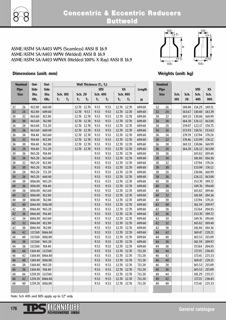
ConcentrConcentric & Eccentric & Eccentric Ric ReducereducerssButtwButtweldeld
176 General catalogueGeneral catalogue
ASME/ASTM SA/A403 WPS (Seamless) ANSI B 16.9ASME/ASTM SA/A403 WPW (Welded) ANSI B 16.9ASME/ASTM SA/A403 WPWX (Welded/100% X Ray) ANSI B 16.9
Dimensions (unit: mm) Weights (unit: kg)
Nominal Out- Out- Wall Thickness (T1, T2) NominalPipe Side Side STD XS Length Pipe STD XSSize Dia. Dia. Sch. 10S Sch. 20 Sch. 40S Sch. 80S Size Sch. Sch. Sch. Sch.
OD1 OD2 T1 T2 T1 T2 T1 T2 T1 T2 H 10S 20 40S 80S
32 26 812.80 660.40 12.70 12.70 9.53 9.53 12.70 12.70 609.60 32 26 148.80 114.29 148.5132 24 812.80 609.60 12.70 9.53 9.53 9.53 12.70 12.70 609.60 32 24 143.67 110.40 143.3934 32 863.60 812.80 12.70 12.70 9.53 9.53 12.70 12.70 609.60 34 32 169.33 130.06 168.9934 30 863.60 762.00 12.70 12.70 9.53 9.53 12.70 12.70 609.60 34 30 164.20 126.12 163.8834 28 863.60 711.20 12.70 12.70 9.53 9.53 12.70 12.70 609.60 34 28 159.07 122.17 158.7534 26 863.60 660.40 12.70 12.70 9.53 9.53 12.70 12.70 609.60 34 26 153.93 118.51 153.6336 34 914.40 863.60 12.70 12.70 9.53 9.53 12.70 12.70 609.60 36 34 179.59 137.94 179.2436 32 914.40 812.80 12.70 12.70 9.53 9.53 12.70 12.70 609.60 36 32 174.46 133.99 174.1236 30 914.40 762.00 12.70 12.70 9.53 9.53 12.70 12.70 609.60 36 30 169.33 130.06 168.9936 28 914.40 711.20 12.70 12.70 9.53 9.53 12.70 12.70 609.60 36 28 164.20 126.12 163.8838 36 965.20 914.40 9.53 9.53 12.70 12.70 609.60 38 36 145.82 189.4838 34 965.20 863.60 9.53 9.53 12.70 12.70 609.60 38 34 141.88 184.3638 32 965.20 812.80 9.53 9.53 12.70 12.70 609.60 38 32 137.94 179.2438 30 965.20 762.00 9.53 9.53 12.70 12.70 609.60 38 30 133.99 174.1238 28 965.20 711.20 9.53 9.53 12.70 12.70 609.60 38 28 130.06 168.9938 26 965.20 660.40 9.53 9.53 12.70 12.70 609.60 38 26 126.12 163.8840 38 1016.00 965.20 9.53 9.53 12.70 12.70 609.60 40 38 153.70 199.7240 36 1016.00 914.40 9.53 9.53 12.70 12.70 609.60 40 36 149.76 194.6040 34 1016.00 863.60 9.53 9.53 12.70 12.70 609.60 40 34 145.82 189.4640 32 1016.00 812.80 9.53 9.53 12.70 12.70 609.60 40 32 141.88 184.3640 30 1016.00 762.00 9.53 9.53 12.70 12.70 609.60 40 30 137.94 179.2442 40 1066.80 1016.00 9.53 9.53 12.70 12.70 609.60 42 40 161.59 209.9742 38 1066.80 965.20 9.53 9.53 12.70 12.70 609.60 42 38 157.64 204.8542 36 1066.80 914.40 9.53 9.53 12.70 12.70 609.60 42 36 153.70 199.7242 34 1066.80 863.60 9.53 9.53 12.70 12.70 609.60 42 34 149.76 194.6042 32 1066.80 812.80 9.53 9.53 12.70 12.70 609.60 42 32 145.82 189.4842 30 1066.80 762.00 9.53 9.53 12.70 12.70 609.60 42 30 141.88 184.3644 42 1117.60 1066.80 9.53 9.53 12.70 12.70 609.60 44 42 169.47 220.2144 40 1117.60 1016.00 9.53 9.53 12.70 12.70 609.60 44 40 165.53 215.0944 38 1117.60 965.20 9.53 9.53 12.70 12.70 609.60 44 38 161.59 209.9744 36 1117.60 914.40 9.53 9.53 12.70 12.70 609.60 44 36 157.64 204.8546 44 1168.40 1117.60 9.53 9.53 12.70 12.70 711.20 46 44 177.35 230.4546 42 1168.40 1066.80 9.53 9.53 12.70 12.70 711.20 46 42 173.41 225.3346 40 1168.40 1016.00 9.53 9.53 12.70 12.70 711.20 46 40 169.47 220.2146 38 1168.40 965.20 9.53 9.53 12.70 12.70 711.20 46 38 165.53 215.0946 36 1168.40 914.40 9.53 9.53 12.70 12.70 711.20 46 36 165.53 215.0948 44 1219.20 1117.60 9.53 9.53 12.70 12.70 711.20 48 44 181.29 235.5748 42 1219.20 1066.80 9.53 9.53 12.70 12.70 711.20 48 42 177.35 230.4548 40 1219.20 1016.00 9.53 9.53 12.70 12.70 711.20 48 40 173.41 225.33
Note: Sch 40S and 80S apply up to 12" only
O.D.1
O.D.2 O.D.2T2
T1
T2
O.D.1T1
H H
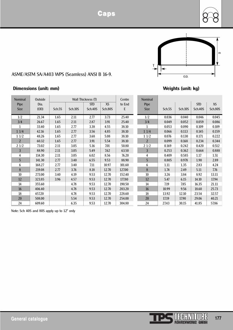
Dimensions (unit: mm) Weights (unit: kg)
Nominal Outside Wall Thickness (T) Centre NominalPipe Dia. STD XS to End Pipe STD XSSize (OD) Sch.5S Sch.10S Sch.40S Sch.80S E Size Sch.5S Sch.10S Sch.40S Sch.80S
1/2 21.34 1.65 2.11 2.77 3.73 25.40 1/2 0.036 0.040 0.046 0.0453/4 26.67 1.65 2.11 2.87 3.91 25.40 3/4 0.049 0.052 0.059 0.0861 33.40 1.65 2.77 3.38 4.55 38.10 1 0.053 0.090 0.109 0.109
1 1/4 42.16 1.65 2.77 3.56 4.85 38.10 1 1/4 0.066 0.113 0.145 0.1591 1/2 48.26 1.65 2.77 3.68 5.08 38.10 1 1/2 0.076 0.130 0.171 0.222
2 60.32 1.65 2.77 3.91 5.54 38.10 2 0.099 0.168 0.234 0.3442 1/2 73.02 2.11 3.05 5.16 7.01 50.80 2 1/2 0.169 0.242 0.420 0.512
3 88.90 2.11 3.05 5.49 7.62 63.50 3 0.253 0.362 0.664 0.8884 114.30 2.11 3.05 6.02 8.56 76.20 4 0.409 0.585 1.17 1.515 141.30 2.77 3.40 6.55 9.53 88.90 5 0.805 0.978 1.90 2.896 168.27 2.77 3.40 7.11 10.97 101.60 6 1.11 1.35 2.83 4.248 219.08 2.77 3.76 8.18 12.70 127.00 8 1.74 2.49 5.11 7.7610 273.00 3.40 4.19 9.53 12.70 152.40 10 3.26 3.84 8.92 13.1112 323.85 3.96 4.57 9.53 12.70 177.80 12 5.47 6.15 14.10 17.9414 355.60 4.78 9.53 12.70 190.50 14 7.19 7.85 16.35 21.1116 406.40 4.78 9.53 12.70 203.20 16 10.99 9.56 18.60 25.7318 457.20 4.78 9.53 12.70 228.60 18 13.92 12.10 23.54 32.5720 508.00 5.54 9.53 12.70 254.00 20 17.19 17.90 29.06 40.2124 609.60 6.35 9.53 12.70 304.80 24 27.43 30.15 41.85 57.86
CapsCaps
General catalogueGeneral catalogue 177
ASME/ASTM SA/A403 WPS (Seamless) ANSI B 16-9.
Note: Sch 40S and 80S apply up to 12" only
O.D.
T
m
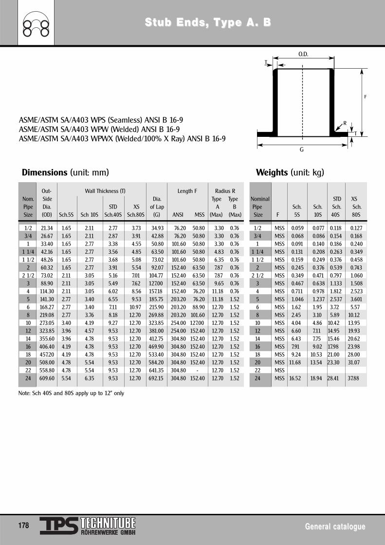
Dimensions (unit: mm) Weights (unit: kg)
Out- Wall Thickness (T) Length F Radius RNom. Side Dia. Type Type Nominal STD XSPipe Dia. STD XS of Lap A B Pipe Sch. Sch. Sch. Sch.Size (OD) Sch.5S Sch 10S Sch.40S Sch.80S (G) ANSI MSS (Max) (Max) Size F 5S 10S 40S 80S
1/2 21.34 1.65 2.11 2.77 3.73 34.93 76.20 50.80 3.30 0.76 1/2 MSS 0.059 0.077 0.118 0.1273/4 26.67 1.65 2.11 2.87 3.91 42.88 76.20 50.80 3.30 0.76 3/4 MSS 0.068 0.086 0.154 0.1681 33.40 1.65 2.77 3.38 4.55 50.80 101.60 50.80 3.30 0.76 1 MSS 0.091 0.140 0.186 0.240
1 1/4 42.16 1.65 2.77 3.56 4.85 63.50 101.60 50.80 4.83 0.76 1 1/4 MSS 0.131 0.208 0.263 0.3491 1/2 48.26 1.65 2.77 3.68 5.08 73.02 101.60 50.80 6.35 0.76 1 1/2 MSS 0.159 0.249 0.376 0.458
2 60.32 1.65 2.77 3.91 5.54 92.07 152.40 63.50 7.87 0.76 2 MSS 0.245 0.376 0.539 0.7432 1/2 73.02 2.11 3.05 5.16 7.01 104.77 152.40 63.50 7.87 0.76 2 1/2 MSS 0.349 0.471 0.797 1.060
3 88.90 2.11 3.05 5.49 7.62 127.00 152.40 63.50 9.65 0.76 3 MSS 0.467 0.638 1.133 1.5084 114.30 2.11 3.05 6.02 8.56 157.18 152.40 76.20 11.18 0.76 4 MSS 0.711 0.978 1.812 2.5235 141.30 2.77 3.40 6.55 9.53 185.75 203.20 76.20 11.18 1.52 5 MSS 1.046 1.237 2.537 3.6016 168.27 2.77 3.40 7.11 10.97 215.90 203.20 88.90 12.70 1.52 6 MSS 1.62 1.95 3.72 5.578 219.08 2.77 3.76 8.18 12.70 269.88 203.20 101.60 12.70 1.52 8 MSS 2.45 3.10 5.89 10.1210 273.05 3.40 4.19 9.27 12.70 323.85 254.00 127.00 12.70 1.52 10 MSS 4.04 4.86 10.42 13.9512 323.85 3.96 4.57 9.53 12.70 381.00 254.00 152.40 12.70 1.52 12 MSS 6.60 7.11 14.95 19.9314 355.60 3.96 4.78 9.53 12.70 412.75 304.80 152.40 12.70 1.52 14 MSS 6.43 7.75 15.46 20.6216 406.40 4.19 4.78 9.53 12.70 469.90 304.80 152.40 12.70 1.52 16 MSS 7.91 9.02 17.98 23.9818 457.20 4.19 4.78 9.53 12.70 533.40 304.80 152.40 12.70 1.52 18 MSS 9.24 10.53 21.00 28.0020 508.00 4.78 5.54 9.53 12.70 584.20 304.80 152.40 12.70 1.52 20 MSS 11.68 13.54 23.30 31.0722 558.80 4.78 5.54 9.53 12.70 641.35 304.80 - 12.70 1.52 22 MSS24 609.60 5.54 6.35 9.53 12.70 692.15 304.80 152.40 12.70 1.52 24 MSS 16.52 18.94 28.41 37.88
SStub Ends, Ttub Ends, Type Aype A . B. B
178 General catalogueGeneral catalogue
ASME/ASTM SA/A403 WPS (Seamless) ANSI B 16-9ASME/ASTM SA/A403 WPW (Welded) ANSI B 16-9ASME/ASTM SA/A403 WPWX (Welded/100% X Ray) ANSI B 16-9
Note: Sch 40S and 80S apply up to 12" only
G
O.D.T
R
T
F
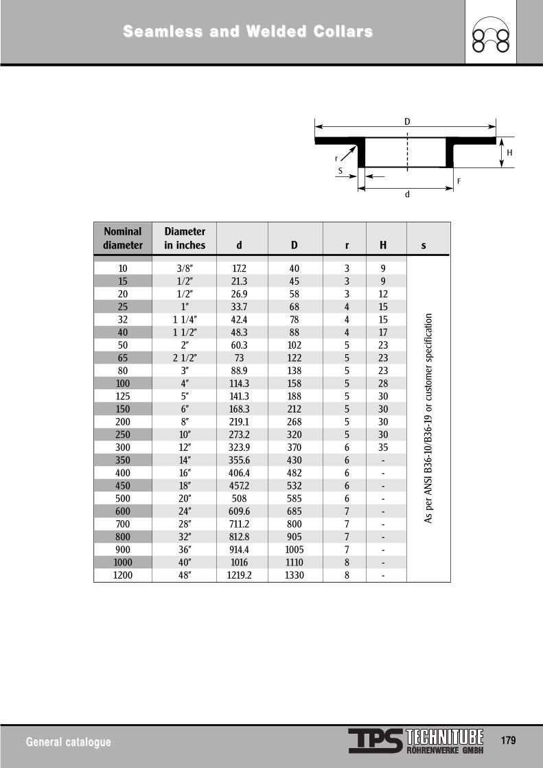
Seamless and WSeamless and Welded Collarelded Collarss
General catalogueGeneral catalogue 179
Nominal Diameterdiameter in inches d D r H s
10 3/8" 17.2 40 3 915 1/2" 21.3 45 3 920 1/2" 26.9 58 3 1225 1" 33.7 68 4 1532 1 1/4" 42.4 78 4 1540 1 1/2" 48.3 88 4 1750 2" 60.3 102 5 2365 2 1/2" 73 122 5 2380 3" 88.9 138 5 23100 4" 114.3 158 5 28125 5" 141.3 188 5 30150 6" 168.3 212 5 30200 8" 219.1 268 5 30250 10" 273.2 320 5 30300 12" 323.9 370 6 35350 14" 355.6 430 6 -400 16" 406.4 482 6 -450 18" 457.2 532 6 -500 20" 508 585 6 -600 24" 609.6 685 7 -700 28" 711.2 800 7 -800 32" 812.8 905 7 -900 36" 914.4 1005 7 -1000 40" 1016 1110 8 -1200 48" 1219.2 1330 8 -
As p
er A
NSI
B36
-10/
B36-
19 o
r cus
tom
er s
peci
ficat
ion
d
D
S
rH
F
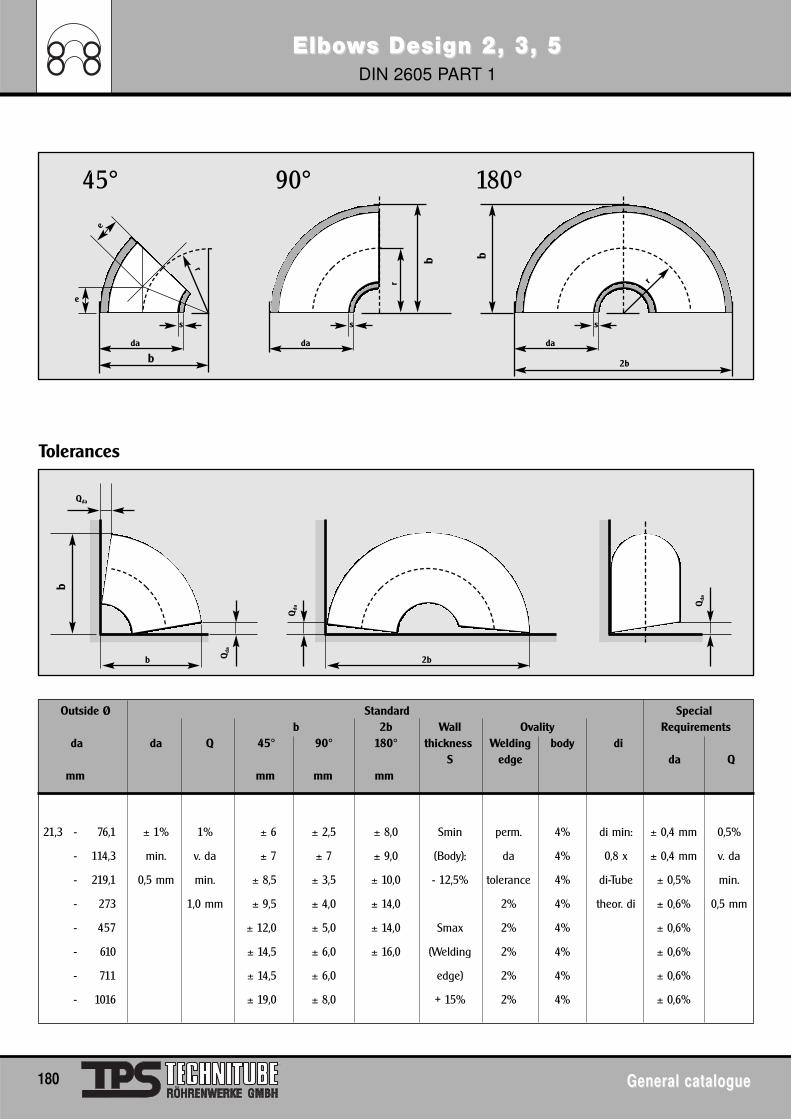
ElboElbowws Design 2, 3, 5s Design 2, 3, 5DIN 2605 PART 1
180 General catalogueGeneral catalogue
Outside Ø Standard Specialb 2b Wall Ovality Requirements
da da Q 45° 90° 180° thickness Welding body diS edge da Q
mm mm mm mm
21,3 - 76,1 ± 1% 1% ± 6 ± 2,5 ± 8,0 Smin perm. 4% di min: ± 0,4 mm 0,5%
- 114,3 min. v. da ± 7 ± 7 ± 9,0 (Body): da 4% 0,8 x ± 0,4 mm v. da
- 219,1 0,5 mm min. ± 8,5 ± 3,5 ± 10,0 - 12,5% tolerance 4% di-Tube ± 0,5% min.
- 273 1,0 mm ± 9,5 ± 4,0 ± 14,0 2% 4% theor. di ± 0,6% 0,5 mm
- 457 ± 12,0 ± 5,0 ± 14,0 Smax 2% 4% ± 0,6%
- 610 ± 14,5 ± 6,0 ± 16,0 (Welding 2% 4% ± 0,6%
- 711 ± 14,5 ± 6,0 edge) 2% 4% ± 0,6%
- 1016 ± 19,0 ± 8,0 + 15% 2% 4% ± 0,6%
Tolerances
b
da
2b
s
180°
r
b
b
da
s
90°
b Qda
r
bda
e
e
s
45°
r
2b
Qda
Qda
Qda
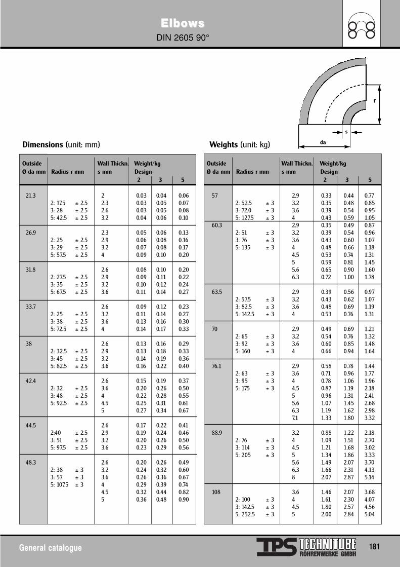
ElboElbowwssDIN 2605 90°
General catalogueGeneral catalogue 181
s
r
Dimensions (unit: mm) Weights (unit: kg)
Outside Wall Thickn. Weight/kg Outside Wall Thickn. Weight/kgØ da mm Radius r mm s mm Design Ø da mm Radius r mm s mm Design
2 3 5 2 3 5
21.3 2 0.03 0.04 0.06 57 2.9 0.33 0.44 0.772: 17.5 ± 2.5 2.3 0.03 0.05 0.07 2: 52.5 ± 3 3.2 0.35 0.48 0.853: 28 ± 2.5 2.6 0.03 0.05 0.08 3: 72.0 ± 3 3.6 0.39 0.54 0.955: 42.5 ± 2.5 3.2 0.04 0.06 0.10 5: 127.5 ± 3 4 0.43 0.59 1.05
60.3 2.9 0.35 0.49 0.8726.9 2.3 0.05 0.06 0.13 2: 51 ± 3 3.2 0.39 0.54 0.96
2: 25 ± 2.5 2.9 0.06 0.08 0.16 3: 76 ± 3 3.6 0.43 0.60 1.073: 29 ± 2.5 3.2 0.07 0.08 0.17 5: 135 ± 3 4 0.48 0.66 1.185: 57.5 ± 2.5 4 0.09 0.10 0.20 4.5 0.53 0.74 1.31
5 0.59 0.81 1.4531.8 2.6 0.08 0.10 0.20 5.6 0.65 0.90 1.60
2: 27.5 ± 2.5 2.9 0.09 0.11 0.22 6.3 0.72 1.00 1.783: 35 ± 2.5 3.2 0.10 0.12 0.245: 67.5 ± 2.5 3.6 0.11 0.14 0.27 63.5 2.9 0.39 0.56 0.97
2: 57.5 ± 3 3.2 0.43 0.62 1.0733.7 2.6 0.09 0.12 0.23 3: 82.5 ± 3 3.6 0.48 0.69 1.19
2: 25 ± 2.5 3.2 0.11 0.14 0.27 5: 142.5 ± 3 4 0.53 0.76 1.313: 38 ± 2.5 3.6 0.13 0.16 0.305: 72.5 ± 2.5 4 0.14 0.17 0.33 70 2.9 0.49 0.69 1.21
2: 65 ± 3 3.2 0.54 0.76 1.3238 2.6 0.13 0.16 0.29 3: 92 ± 3 3.6 0.60 0.85 1.48
2: 32.5 ± 2.5 2.9 0.13 0.18 0.33 5: 160 ± 3 4 0.66 0.94 1.643: 45 ± 2.5 3.2 0.14 0.19 0.365: 82.5 ± 2.5 3.6 0.16 0.22 0.40 76.1 2.9 0.58 0.78 1.44
2: 63 ± 3 3.6 0.71 0.96 1.7742.4 2.6 0.15 0.19 0.37 3: 95 ± 3 4 0.78 1.06 1.96
2: 32 ± 2.5 3.6 0.20 0.26 0.50 5: 175 ± 3 4.5 0.87 1.19 2.183: 48 ± 2.5 4 0.22 0.28 0.55 5 0.96 1.31 2.415: 92.5 ± 2.5 4.5 0.25 0.31 0.61 5.6 1.07 1.45 2.68
5 0.27 0.34 0.67 6.3 1.19 1.62 2.987.1 1.33 1.80 3.32
44.5 2.6 0.17 0.22 0.412:40 ± 2.5 2.9 0.19 0.24 0.46 88.9 3.2 0.88 1.22 2.183: 51 ± 2.5 3.2 0.20 0.26 0.50 2: 76 ± 3 4 1.09 1.51 2.705: 97.5 ± 2.5 3.6 0.23 0.29 0.56 3: 114 ± 3 4.5 1.21 1.68 3.02
5: 205 ± 3 5 1.34 1.86 3.3348.3 2.6 0.20 0.26 0.49 5.6 1.49 2.07 3.70
2: 38 ± 3 3.2 0.24 0.32 0.60 6.3 1.66 2.31 4.133: 57 ± 3 3.6 0.26 0.36 0.67 8 2.07 2.87 5.145: 107.5 ± 3 4 0.29 0.39 0.74
4.5 0.32 0.44 0.82 108 3.6 1.46 2.07 3.685 0.36 0.48 0.90 2: 100 ± 3 4 1.61 2.30 4.07
3: 142.5 ± 3 4.5 1.80 2.57 4.565: 252.5 ± 3 5 2.00 2.84 5.04
da
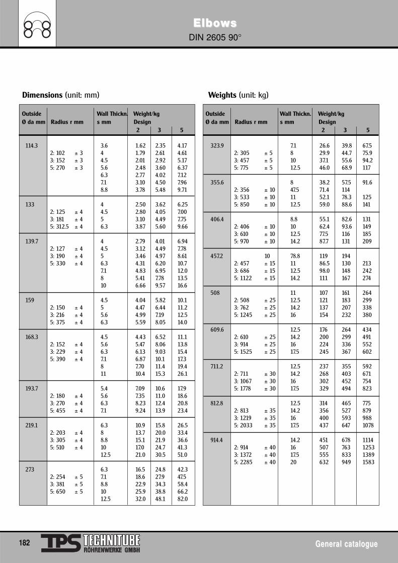
ElboElbowwssDIN 2605 90°
182 General catalogueGeneral catalogue
Dimensions (unit: mm) Weights (unit: kg)
Outside Wall Thickn. Weight/kg Outside Wall Thickn. Weight/kgØ da mm Radius r mm s mm Design Ø da mm Radius r mm s mm Design
2 3 5 2 3 5
114.3 3.6 1.62 2.35 4.17 323.9 7.1 26.6 39.8 67.52: 102 ± 3 4 1.79 2.61 4.61 2: 305 ± 5 8 29.9 44.7 75.93: 152 ± 3 4.5 2.01 2.92 5.17 3: 457 ± 5 10 37.1 55.6 94.25: 270 ± 3 5.6 2.48 3.60 6.37 5: 775 ± 5 12.5 46.0 68.9 117
6.3 2.77 4.02 7.127.1 3.10 4.50 7.96 355.6 8 38.2 57.5 91.68.8 3.78 5.48 9.71 2: 356 ± 10 47.5 71.4 114
3: 533 ± 10 11 52.1 78.3 125133 4 2.50 3.62 6.25 5: 850 ± 10 12.5 59.0 88.6 141
2: 125 ± 4 4.5 2.80 4.05 7.003: 181 ± 4 5 3.10 4.49 7.75 406.4 8.8 55.1 82.6 1315: 312.5 ± 4 6.3 3.87 5.60 9.66 2: 406 ± 10 10 62.4 93.6 149
3: 610 ± 10 12.5 77.5 116 185139.7 4 2.79 4.01 6.94 5: 970 ± 10 14.2 87.7 131 209
2: 127 ± 4 4.5 3.12 4.49 7.783: 190 ± 4 5 3.46 4.97 8.61 457.2 10 78.8 119 1945: 330 ± 4 6.3 4.31 6.20 10.7 2: 457 ± 15 11 86.5 130 213
7.1 4.83 6.95 12.0 3: 686 ± 15 12.5 98.0 148 2428 5.41 7.78 13.5 5: 1122 ± 15 14.2 111 167 27410 6.66 9.57 16.6
508 11 107 161 264159 4.5 4.04 5.82 10.1 2: 508 ± 25 12.5 121 183 299
2: 150 ± 4 5 4.47 6.44 11.2 3: 762 ± 25 14.2 137 207 3383: 216 ± 4 5.6 4.99 7.19 12.5 5: 1245 ± 25 16 154 232 3805: 375 ± 4 6.3 5.59 8.05 14.0
609.6 12.5 176 264 434168.3 4.5 4.43 6.52 11.1 2: 610 ± 25 14.2 200 299 491
2: 152 ± 4 5.6 5.47 8.06 13.8 3: 914 ± 25 16 224 336 5523: 229 ± 4 6.3 6.13 9.03 15.4 5: 1525 ± 25 17.5 245 367 6025: 390 ± 4 7.1 6.87 10.1 17.3
8 7.70 11.4 19.4 711.2 12.5 237 355 59211 10.4 15.3 26.1 2: 711 ± 30 14.2 268 403 671
3: 1067 ± 30 16 302 452 754193.7 5.4 7.09 10.6 17.9 5: 1778 ± 30 17.5 329 494 823
2: 180 ± 4 5.6 7.35 11.0 18.63: 270 ± 4 6.3 8.23 12.4 20.8 812.8 12.5 314 465 7755: 455 ± 4 7.1 9.24 13.9 23.4 2: 813 ± 35 14.2 356 527 879
3: 1219 ± 35 16 400 593 988219.1 6.3 10.9 15.8 26.5 5: 2033 ± 35 17.5 437 647 1078
2: 203 ± 4 8 13.7 20.0 33.43: 305 ± 4 8.8 15.1 21.9 36.6 914.4 14.2 451 678 11145: 510 ± 4 10 17.0 24.7 41.3 2: 914 ± 40 16 507 763 1253
12.5 21.0 30.5 51.0 3: 1372 ± 40 17.5 555 833 13895: 2285 ± 40 20 632 949 1583
273 6.3 16.5 24.8 42.32: 254 ± 5 7.1 18.6 27.9 47.53: 381 ± 5 8.8 22.9 34.3 58.45: 650 ± 5 10 25.9 38.8 66.2
12.5 32.0 48.1 82.0
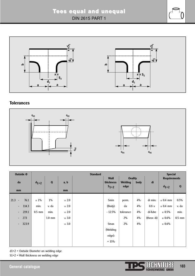
TTees eqees equal and unequal and unequalualDIN 2615 PART 1
General catalogueGeneral catalogue 183
Outside Ø Standard SpecialWall Ovality Requirements
da d1+2 Q a, b thickness Welding body diS1+2 edge d1+2 Q
mm mm
21.3 - 76.1 ± 1% 1% ± 2.0 Smin perm. 4% di min: ± 0.4 mm 0.5%
- 114.3 min. v. da ± 2.0 (Body): da 4% 0.8 x ± 0.4 mm v. da
- 219.1 0.5 mm min. ± 2.0 - 12.5% tolerance 4% di-Tube ± 0.5% min.
- 273 1.0 mm ± 3.0 2% 4% (theor. di) ± 0.6% 0.5 mm
- 323.9 ± 3.0 Smax 2% 4% ± 0.6%
(Welding
edge):
+ 15%
Tolerances
Qd2
Qd1
d2
b
a a
d 1
S2
S 1
d2
b
a a
d 1
S2
S 1
Qd1
Qd1Qd1
d1+2 = Outside Diameter on welding edgeS1+2 = Wall thickness on welding edge
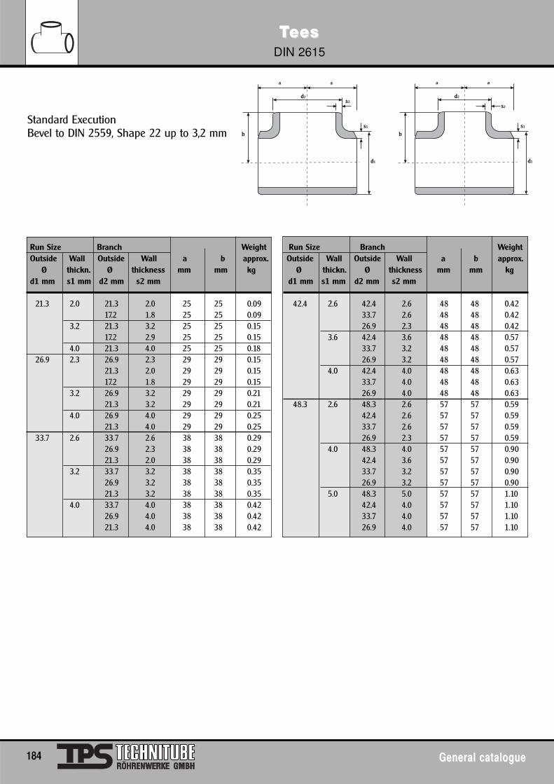
TTeeseesDIN 2615
184 General catalogueGeneral catalogue
a a
d2s2
s1
d1
b
a a
d2
s2
s1
d1
b
Standard ExecutionBevel to DIN 2559, Shape 22 up to 3,2 mm
Run Size Branch Weight Run Size Branch WeightOutside Wall Outside Wall a b approx. Outside Wall Outside Wall a b approx.
Ø thickn. Ø thickness mm mm kg Ø thickn. Ø thickness mm mm kgd1 mm s1 mm d2 mm s2 mm d1 mm s1 mm d2 mm s2 mm
21.3 2.0 21.3 2.0 25 25 0.09 42.4 2.6 42.4 2.6 48 48 0.4217.2 1.8 25 25 0.09 33.7 2.6 48 48 0.42
3.2 21.3 3.2 25 25 0.15 26.9 2.3 48 48 0.4217.2 2.9 25 25 0.15 3.6 42.4 3.6 48 48 0.57
4.0 21.3 4.0 25 25 0.18 33.7 3.2 48 48 0.5726.9 2.3 26.9 2.3 29 29 0.15 26.9 3.2 48 48 0.57
21.3 2.0 29 29 0.15 4.0 42.4 4.0 48 48 0.6317.2 1.8 29 29 0.15 33.7 4.0 48 48 0.63
3.2 26.9 3.2 29 29 0.21 26.9 4.0 48 48 0.6321.3 3.2 29 29 0.21 48.3 2.6 48.3 2.6 57 57 0.59
4.0 26.9 4.0 29 29 0.25 42.4 2.6 57 57 0.5921.3 4.0 29 29 0.25 33.7 2.6 57 57 0.59
33.7 2.6 33.7 2.6 38 38 0.29 26.9 2.3 57 57 0.5926.9 2.3 38 38 0.29 4.0 48.3 4.0 57 57 0.9021.3 2.0 38 38 0.29 42.4 3.6 57 57 0.90
3.2 33.7 3.2 38 38 0.35 33.7 3.2 57 57 0.9026.9 3.2 38 38 0.35 26.9 3.2 57 57 0.9021.3 3.2 38 38 0.35 5.0 48.3 5.0 57 57 1.10
4.0 33.7 4.0 38 38 0.42 42.4 4.0 57 57 1.1026.9 4.0 38 38 0.42 33.7 4.0 57 57 1.1021.3 4.0 38 38 0.42 26.9 4.0 57 57 1.10
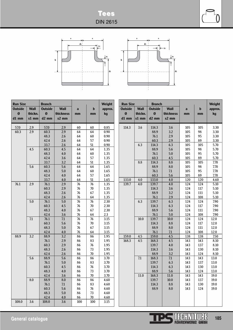
TTeeseesDIN 2615
General catalogueGeneral catalogue 185
a a
d2s2
s1
d1
b
a a
d2
s2
s1
d1
b
Run Size Branch Weight Run Size Branch WeightOutside Wall Outside Wall a b approx. Outside Wall Outside Wall a b approx.
Ø thickn. Ø thickness mm mm kg Ø thickn. Ø thickness mm mm kgd1 mm s1 mm d2 mm s2 mm d1 mm s1 mm d2 mm s2 mm
57.0 2.9 57.0 2.9 60 60 0.85 114.3 3.6 114.3 3.6 105 105 3.3060.3 2.9 60.3 2.9 64 64 0.90 88.9 3.2 105 98 3.30
48.3 2.6 64 60 0.90 76.1 2.9 105 95 3.3042.4 2.6 64 57 0.90 60.3 2.9 105 89 3.3033.7 2.6 64 51 0.90 6.3 114.3 6.3 105 105 5.70
4.5 60.3 4.5 64 64 1.35 88.9 5.6 105 98 5.7048.3 4.0 64 60 1.35 76.1 5.0 105 95 5.7042.4 3.6 64 57 1.35 60.3 4.5 105 89 5.7033.7 3.2 64 51 1.35 8.8 114.3 8.8 105 105 7.70
5.6 60.3 5.6 64 64 1.65 88.9 8.0 105 98 7.7048.3 5.0 64 60 1.65 76.1 7.1 105 95 7.7042.4 4.0 64 57 1.65 60.3 5.6 105 89 7.7033.7 4.0 64 51 1.65 133.0 4.0 133.0 4.0 120 120 4.60
76.1 2.9 76.1 2.9 76 76 1.35 139.7 4.0 139.7 4.0 124 124 5.1060.3 2.9 76 70 1.35 114.3 3.6 124 117 5.1048.3 2.6 76 67 1.35 88.9 3.2 124 111 5.1042.4 2.6 76 64 1.35 76.1 2.9 124 108 5.10
5.0 76.1 5.0 76 76 2.30 6.3 139.7 6.3 124 124 7.9060.3 4.5 76 70 2.30 114.3 6.3 124 117 7.9048.3 4.0 76 67 2.30 88.9 5.6 124 111 7.9042.4 3.6 76 64 2.3 76.1 5.0 124 108 7.90
7.1 76.1 7.1 76 76 3.15 10.0 139.7 10.0 124 124 12.060.3 5.6 76 70 3.15 114.3 8.8 124 117 12.048.3 5.0 76 67 3.15 88.9 8.0 124 111 12.042.4 4.0 76 64 3.15 76.1 7.1 124 108 12.0
88.9 3.2 88.9 3.2 86 86 1.95 159.0 4.5 159.0 4.5 138 138 7.5076.1 2.9 86 83 1.95 168.3 4.5 168.3 4.5 143 143 8.1060.3 2.9 86 76 1.95 139.7 4.0 143 137 8.1048.3 2.6 86 73 1.95 114.3 3.6 143 130 8.1042.4 2.6 86 70 1.95 88.9 3.2 143 124 8.10
5.6 88.9 5.6 86 86 3.70 7.1 168.3 7.1 143 143 13.076.1 5.0 86 83 3.70 139.7 6.3 143 137 13.060.3 4.5 86 76 3.70 114.3 6.3 143 130 13.048.3 4.0 86 73 3.70 88.9 5.6 143 124 13.042.4 3.6 86 70 3.70 11.0 168.3 11.0 143 143 19.0
8.0 88.9 8.0 86 86 4.60 139.7 10.0 143 137 19.076.1 7.1 86 83 4.60 114.3 8.8 143 130 19.060.3 5.6 86 76 4.60 88.9 8.0 143 124 19.048.3 5.0 86 73 4.6042.4 4.0 86 70 4.60
108.0 3.6 108.0 3.6 100 100 3.15
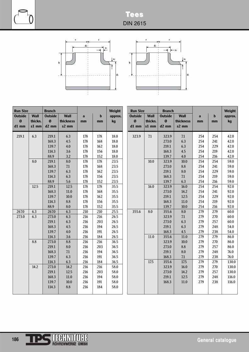
TTeeseesDIN 2615
186 General catalogueGeneral catalogue
a a
d2s2
s1
d1
b
a a
d2
s2
s1
d1
b
Run Size Branch Weight Run Size Branch WeightOutside Wall Outside Wall a b approx. Outside Wall Outside Wall a b approx.
Ø thickn. Ø thickness mm mm kg Ø thickn. Ø thickness mm mm kgd1 mm s1 mm d2 mm s2 mm d1 mm s1 mm d2 mm s2 mm
219.1 6.3 219.1 6.3 178 178 18.0 323.9 7.1 323.9 7.1 254 254 42.0168.3 4.5 178 168 18.0 273.0 6.3 254 241 42.0139.7 4.0 178 162 18.0 219.1 6.3 254 229 42.0114.3 3.6 178 156 18.0 168.3 4.5 254 219 42.088.9 3.2 178 152 18.0 139.7 4.0 254 216 42.0
8.0 219.1 8.0 178 178 23.5 10.0 323.9 10.0 254 254 59.0168.3 7.1 178 168 23.5 273.0 8.8 254 241 59.0139.7 6.3 178 162 23.5 219.1 8.0 254 229 59.0114.3 6.3 178 156 23.5 168.3 7.1 254 219 59.088.9 5.6 178 152 23.5 139.7 6.3 254 216 59.0
12.5 219.1 12.5 178 178 35.5 16.0 323.9 16.0 254 254 92.0168.3 11.0 178 168 35.5 273.0 14.2 254 241 92.0139.7 10.0 178 162 35.5 219.1 12.5 254 229 92.0114.3 8.8 178 156 35.5 168.3 11.0 254 219 92.088.9 8.0 178 152 35.5 139.7 10.0 254 216 92.0
267.0 6.3 267.0 6.3 210 210 25.5 355.6 8.0 355.6 8.0 279 279 60.0273.0 6.3 273.0 6.3 216 216 26.5 323.9 7.1 279 270 60.0
219.1 6.3 216 203 26.5 273.0 6.3 279 257 60.0168.3 4.5 216 194 26.5 219.1 6.3 279 248 54.0139.7 4.0 216 191 26.5 168.3 4.5 279 238 54.0114.3 3.6 216 184 26.5 11.0 355.6 11.0 279 279 86.0
8.8 273.0 8.8 216 216 36.5 323.9 10.0 279 270 86.0219.1 8.0 216 203 36.5 273.0 8.8 279 257 86.0168.3 7.1 216 194 36.5 219.1 8.0 279 248 76.0139.7 6.3 216 191 36.5 168.3 7.1 279 238 76.0114.3 6.3 216 184 36.5 17.5 355.6 17.5 279 279 130.0
14.2 273.0 14.2 216 216 58.0 323.9 16.0 279 270 130.0219.1 12.5 216 203 58.0 273.0 14.2 279 257 130.0168.3 11.0 216 194 58.0 219.1 12.5 279 248 116.0139.7 10.0 216 191 58.0 168.3 11.0 279 238 116.0114.3 8.8 216 184 58.0
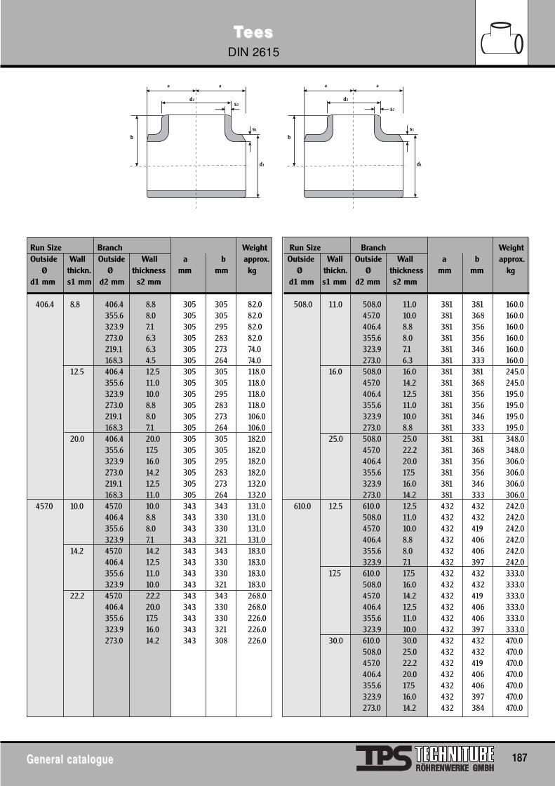
TTeeseesDIN 2615
General catalogueGeneral catalogue 187
a a
d2s2
s1
d1
b
a a
d2
s2
s1
d1
b
Run Size Branch Weight Run Size Branch WeightOutside Wall Outside Wall a b approx. Outside Wall Outside Wall a b approx.
Ø thickn. Ø thickness mm mm kg Ø thickn. Ø thickness mm mm kgd1 mm s1 mm d2 mm s2 mm d1 mm s1 mm d2 mm s2 mm
406.4 8.8 406.4 8.8 305 305 82.0 508.0 11.0 508.0 11.0 381 381 160.0355.6 8.0 305 305 82.0 457.0 10.0 381 368 160.0323.9 7.1 305 295 82.0 406.4 8.8 381 356 160.0273.0 6.3 305 283 82.0 355.6 8.0 381 356 160.0219.1 6.3 305 273 74.0 323.9 7.1 381 346 160.0168.3 4.5 305 264 74.0 273.0 6.3 381 333 160.0
12.5 406.4 12.5 305 305 118.0 16.0 508.0 16.0 381 381 245.0355.6 11.0 305 305 118.0 457.0 14.2 381 368 245.0323.9 10.0 305 295 118.0 406.4 12.5 381 356 195.0273.0 8.8 305 283 118.0 355.6 11.0 381 356 195.0219.1 8.0 305 273 106.0 323.9 10.0 381 346 195.0168.3 7.1 305 264 106.0 273.0 8.8 381 333 195.0
20.0 406.4 20.0 305 305 182.0 25.0 508.0 25.0 381 381 348.0355.6 17.5 305 305 182.0 457.0 22.2 381 368 348.0323.9 16.0 305 295 182.0 406.4 20.0 381 356 306.0273.0 14.2 305 283 182.0 355.6 17.5 381 356 306.0219.1 12.5 305 273 132.0 323.9 16.0 381 346 306.0168.3 11.0 305 264 132.0 273.0 14.2 381 333 306.0
457.0 10.0 457.0 10.0 343 343 131.0 610.0 12.5 610.0 12.5 432 432 242.0406.4 8.8 343 330 131.0 508.0 11.0 432 432 242.0355.6 8.0 343 330 131.0 457.0 10.0 432 419 242.0323.9 7.1 343 321 131.0 406.4 8.8 432 406 242.0
14.2 457.0 14.2 343 343 183.0 355.6 8.0 432 406 242.0406.4 12.5 343 330 183.0 323.9 7.1 432 397 242.0355.6 11.0 343 330 183.0 17.5 610.0 17.5 432 432 333.0323.9 10.0 343 321 183.0 508.0 16.0 432 432 333.0
22.2 457.0 22.2 343 343 268.0 457.0 14.2 432 419 333.0406.4 20.0 343 330 268.0 406.4 12.5 432 406 333.0355.6 17.5 343 330 226.0 355.6 11.0 432 406 333.0323.9 16.0 343 321 226.0 323.9 10.0 432 397 333.0273.0 14.2 343 308 226.0 30.0 610.0 30.0 432 432 470.0
508.0 25.0 432 432 470.0457.0 22.2 432 419 470.0406.4 20.0 432 406 470.0355.6 17.5 432 406 470.0323.9 16.0 432 397 470.0273.0 14.2 432 384 470.0
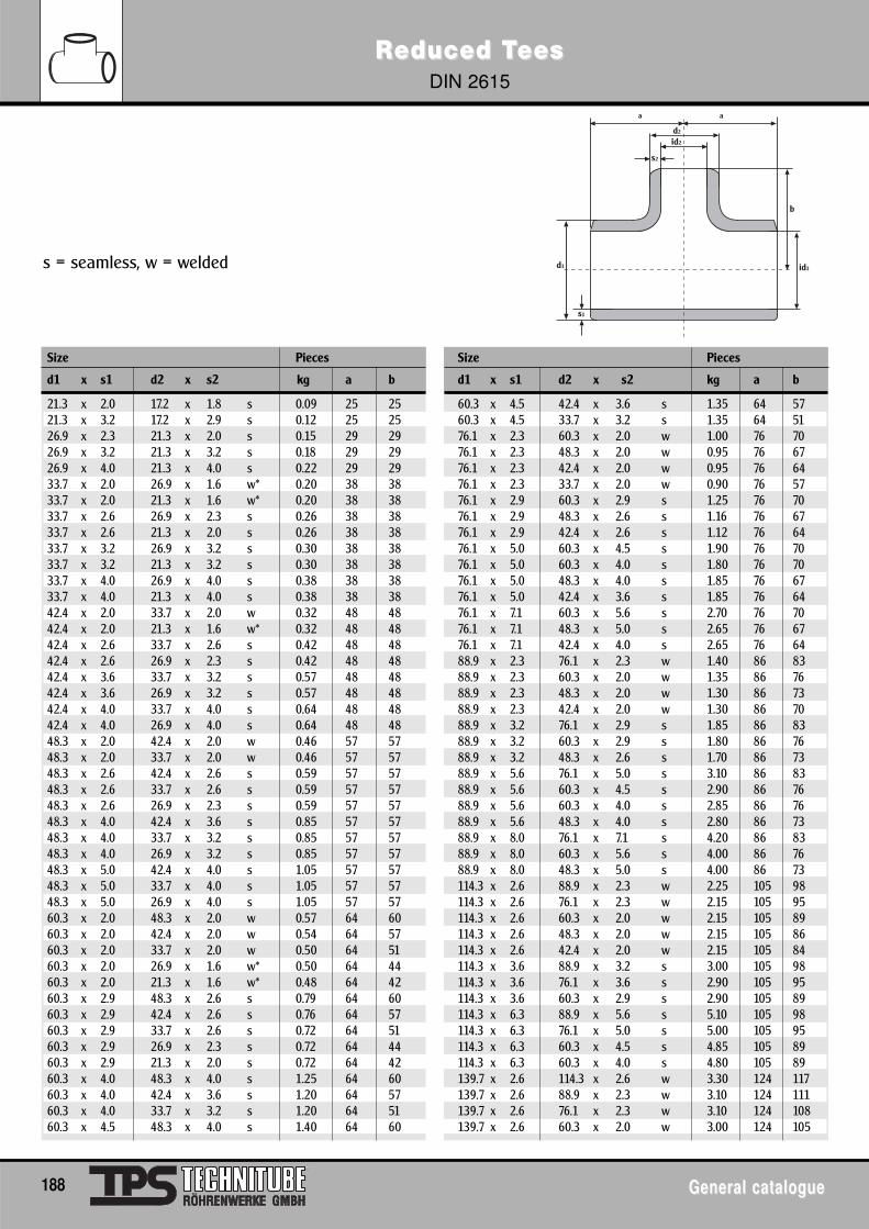
Size Pieces Size Pieces
d1 x s1 d2 x s2 kg a b d1 x s1 d2 x s2 kg a b
21.3 x 2.0 17.2 x 1.8 s 0.09 25 25 60.3 x 4.5 42.4 x 3.6 s 1.35 64 5721.3 x 3.2 17.2 x 2.9 s 0.12 25 25 60.3 x 4.5 33.7 x 3.2 s 1.35 64 5126.9 x 2.3 21.3 x 2.0 s 0.15 29 29 76.1 x 2.3 60.3 x 2.0 w 1.00 76 7026.9 x 3.2 21.3 x 3.2 s 0.18 29 29 76.1 x 2.3 48.3 x 2.0 w 0.95 76 6726.9 x 4.0 21.3 x 4.0 s 0.22 29 29 76.1 x 2.3 42.4 x 2.0 w 0.95 76 6433.7 x 2.0 26.9 x 1.6 w* 0.20 38 38 76.1 x 2.3 33.7 x 2.0 w 0.90 76 5733.7 x 2.0 21.3 x 1.6 w* 0.20 38 38 76.1 x 2.9 60.3 x 2.9 s 1.25 76 7033.7 x 2.6 26.9 x 2.3 s 0.26 38 38 76.1 x 2.9 48.3 x 2.6 s 1.16 76 6733.7 x 2.6 21.3 x 2.0 s 0.26 38 38 76.1 x 2.9 42.4 x 2.6 s 1.12 76 6433.7 x 3.2 26.9 x 3.2 s 0.30 38 38 76.1 x 5.0 60.3 x 4.5 s 1.90 76 7033.7 x 3.2 21.3 x 3.2 s 0.30 38 38 76.1 x 5.0 60.3 x 4.0 s 1.80 76 7033.7 x 4.0 26.9 x 4.0 s 0.38 38 38 76.1 x 5.0 48.3 x 4.0 s 1.85 76 6733.7 x 4.0 21.3 x 4.0 s 0.38 38 38 76.1 x 5.0 42.4 x 3.6 s 1.85 76 6442.4 x 2.0 33.7 x 2.0 w 0.32 48 48 76.1 x 7.1 60.3 x 5.6 s 2.70 76 7042.4 x 2.0 21.3 x 1.6 w* 0.32 48 48 76.1 x 7.1 48.3 x 5.0 s 2.65 76 6742.4 x 2.6 33.7 x 2.6 s 0.42 48 48 76.1 x 7.1 42.4 x 4.0 s 2.65 76 6442.4 x 2.6 26.9 x 2.3 s 0.42 48 48 88.9 x 2.3 76.1 x 2.3 w 1.40 86 8342.4 x 3.6 33.7 x 3.2 s 0.57 48 48 88.9 x 2.3 60.3 x 2.0 w 1.35 86 7642.4 x 3.6 26.9 x 3.2 s 0.57 48 48 88.9 x 2.3 48.3 x 2.0 w 1.30 86 7342.4 x 4.0 33.7 x 4.0 s 0.64 48 48 88.9 x 2.3 42.4 x 2.0 w 1.30 86 7042.4 x 4.0 26.9 x 4.0 s 0.64 48 48 88.9 x 3.2 76.1 x 2.9 s 1.85 86 8348.3 x 2.0 42.4 x 2.0 w 0.46 57 57 88.9 x 3.2 60.3 x 2.9 s 1.80 86 7648.3 x 2.0 33.7 x 2.0 w 0.46 57 57 88.9 x 3.2 48.3 x 2.6 s 1.70 86 7348.3 x 2.6 42.4 x 2.6 s 0.59 57 57 88.9 x 5.6 76.1 x 5.0 s 3.10 86 8348.3 x 2.6 33.7 x 2.6 s 0.59 57 57 88.9 x 5.6 60.3 x 4.5 s 2.90 86 7648.3 x 2.6 26.9 x 2.3 s 0.59 57 57 88.9 x 5.6 60.3 x 4.0 s 2.85 86 7648.3 x 4.0 42.4 x 3.6 s 0.85 57 57 88.9 x 5.6 48.3 x 4.0 s 2.80 86 7348.3 x 4.0 33.7 x 3.2 s 0.85 57 57 88.9 x 8.0 76.1 x 7.1 s 4.20 86 8348.3 x 4.0 26.9 x 3.2 s 0.85 57 57 88.9 x 8.0 60.3 x 5.6 s 4.00 86 7648.3 x 5.0 42.4 x 4.0 s 1.05 57 57 88.9 x 8.0 48.3 x 5.0 s 4.00 86 7348.3 x 5.0 33.7 x 4.0 s 1.05 57 57 114.3 x 2.6 88.9 x 2.3 w 2.25 105 9848.3 x 5.0 26.9 x 4.0 s 1.05 57 57 114.3 x 2.6 76.1 x 2.3 w 2.15 105 9560.3 x 2.0 48.3 x 2.0 w 0.57 64 60 114.3 x 2.6 60.3 x 2.0 w 2.15 105 8960.3 x 2.0 42.4 x 2.0 w 0.54 64 57 114.3 x 2.6 48.3 x 2.0 w 2.15 105 8660.3 x 2.0 33.7 x 2.0 w 0.50 64 51 114.3 x 2.6 42.4 x 2.0 w 2.15 105 8460.3 x 2.0 26.9 x 1.6 w* 0.50 64 44 114.3 x 3.6 88.9 x 3.2 s 3.00 105 9860.3 x 2.0 21.3 x 1.6 w* 0.48 64 42 114.3 x 3.6 76.1 x 3.6 s 2.90 105 9560.3 x 2.9 48.3 x 2.6 s 0.79 64 60 114.3 x 3.6 60.3 x 2.9 s 2.90 105 8960.3 x 2.9 42.4 x 2.6 s 0.76 64 57 114.3 x 6.3 88.9 x 5.6 s 5.10 105 9860.3 x 2.9 33.7 x 2.6 s 0.72 64 51 114.3 x 6.3 76.1 x 5.0 s 5.00 105 9560.3 x 2.9 26.9 x 2.3 s 0.72 64 44 114.3 x 6.3 60.3 x 4.5 s 4.85 105 8960.3 x 2.9 21.3 x 2.0 s 0.72 64 42 114.3 x 6.3 60.3 x 4.0 s 4.80 105 8960.3 x 4.0 48.3 x 4.0 s 1.25 64 60 139.7 x 2.6 114.3 x 2.6 w 3.30 124 11760.3 x 4.0 42.4 x 3.6 s 1.20 64 57 139.7 x 2.6 88.9 x 2.3 w 3.10 124 11160.3 x 4.0 33.7 x 3.2 s 1.20 64 51 139.7 x 2.6 76.1 x 2.3 w 3.10 124 10860.3 x 4.5 48.3 x 4.0 s 1.40 64 60 139.7 x 2.6 60.3 x 2.0 w 3.00 124 105
RReduced Teduced TeeseesDIN 2615
188 General catalogueGeneral catalogue
a a
d2
s2
s1
id1
id2
d1
b
s = seamless, w = welded
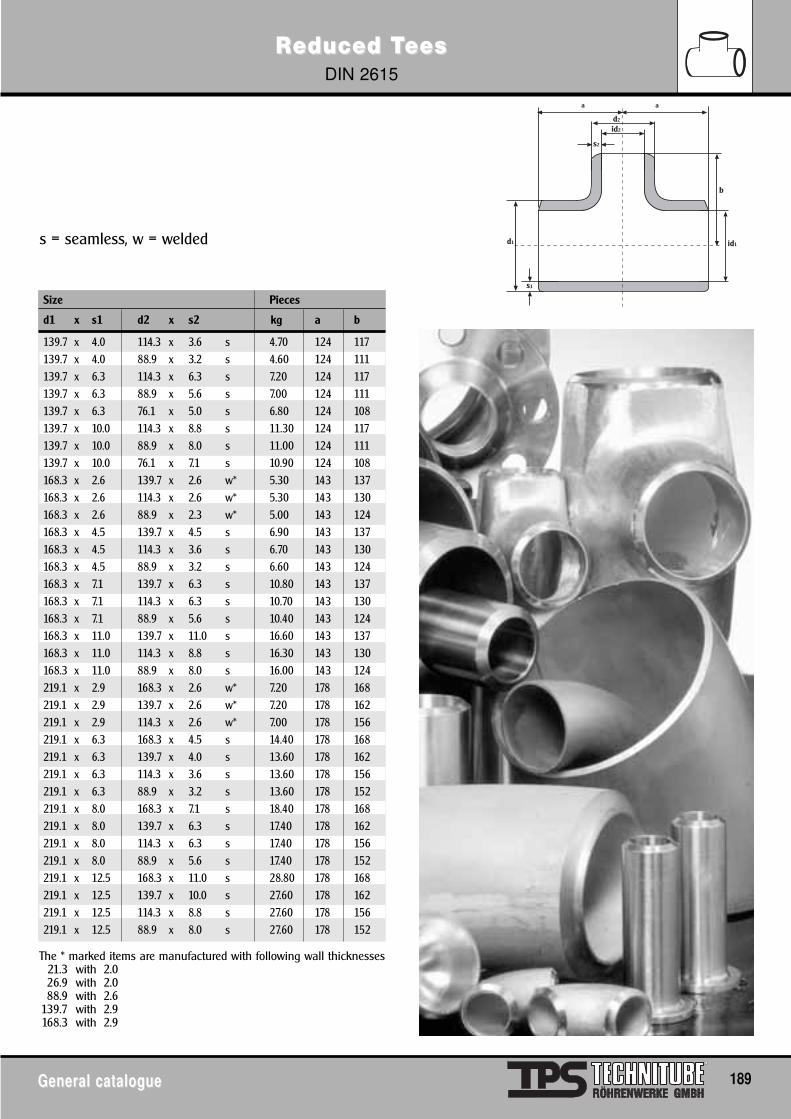
RReduced Teduced TeeseesDIN 2615
General catalogueGeneral catalogue 189
s = seamless, w = welded
Size Pieces
d1 x s1 d2 x s2 kg a b
139.7 x 4.0 114.3 x 3.6 s 4.70 124 117139.7 x 4.0 88.9 x 3.2 s 4.60 124 111139.7 x 6.3 114.3 x 6.3 s 7.20 124 117139.7 x 6.3 88.9 x 5.6 s 7.00 124 111139.7 x 6.3 76.1 x 5.0 s 6.80 124 108139.7 x 10.0 114.3 x 8.8 s 11.30 124 117139.7 x 10.0 88.9 x 8.0 s 11.00 124 111139.7 x 10.0 76.1 x 7.1 s 10.90 124 108168.3 x 2.6 139.7 x 2.6 w* 5.30 143 137168.3 x 2.6 114.3 x 2.6 w* 5.30 143 130168.3 x 2.6 88.9 x 2.3 w* 5.00 143 124168.3 x 4.5 139.7 x 4.5 s 6.90 143 137168.3 x 4.5 114.3 x 3.6 s 6.70 143 130168.3 x 4.5 88.9 x 3.2 s 6.60 143 124168.3 x 7.1 139.7 x 6.3 s 10.80 143 137168.3 x 7.1 114.3 x 6.3 s 10.70 143 130168.3 x 7.1 88.9 x 5.6 s 10.40 143 124168.3 x 11.0 139.7 x 11.0 s 16.60 143 137168.3 x 11.0 114.3 x 8.8 s 16.30 143 130168.3 x 11.0 88.9 x 8.0 s 16.00 143 124219.1 x 2.9 168.3 x 2.6 w* 7.20 178 168219.1 x 2.9 139.7 x 2.6 w* 7.20 178 162219.1 x 2.9 114.3 x 2.6 w* 7.00 178 156219.1 x 6.3 168.3 x 4.5 s 14.40 178 168219.1 x 6.3 139.7 x 4.0 s 13.60 178 162219.1 x 6.3 114.3 x 3.6 s 13.60 178 156219.1 x 6.3 88.9 x 3.2 s 13.60 178 152219.1 x 8.0 168.3 x 7.1 s 18.40 178 168219.1 x 8.0 139.7 x 6.3 s 17.40 178 162219.1 x 8.0 114.3 x 6.3 s 17.40 178 156219.1 x 8.0 88.9 x 5.6 s 17.40 178 152219.1 x 12.5 168.3 x 11.0 s 28.80 178 168219.1 x 12.5 139.7 x 10.0 s 27.60 178 162219.1 x 12.5 114.3 x 8.8 s 27.60 178 156219.1 x 12.5 88.9 x 8.0 s 27.60 178 152
a a
d2
s2
s1
id1
id2
d1
b
The * marked items are manufactured with following wall thicknesses21.3 with 2.026.9 with 2.088.9 with 2.6
139.7 with 2.9168.3 with 2.9
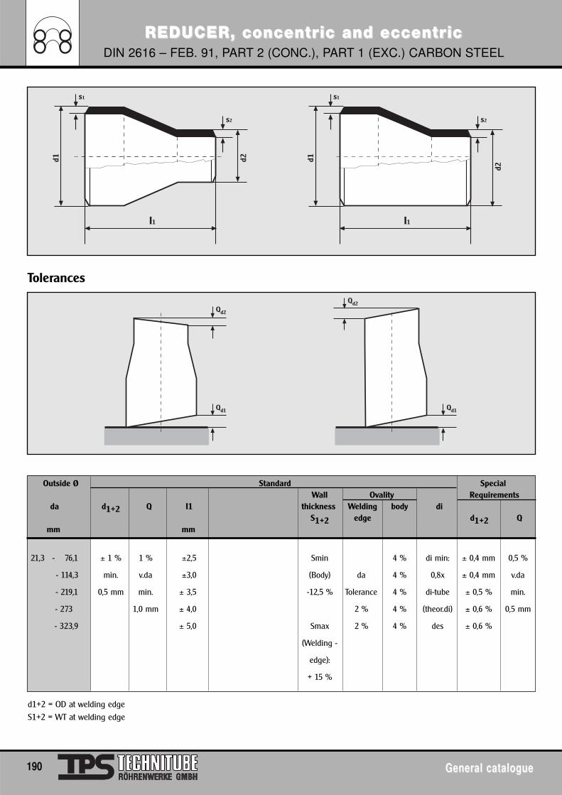
REDUCER, concentrREDUCER, concentric and eccentric and eccentricicDIN 2616 – FEB. 91, PART 2 (CONC.), PART 1 (EXC.) CARBON STEEL
190 General catalogueGeneral catalogue
Outside Ø Standard SpecialWall Ovality Requirements
da d1+2 Q I1 thickness Welding body diS1+2 edge d1+2 Q
mm mm
21,3 - 76,1 ± 1 % 1 % ±2,5 Smin 4 % di min: ± 0,4 mm 0,5 %
- 114,3 min. v.da ±3,0 (Body) da 4 % 0,8x ± 0,4 mm v.da
- 219,1 0,5 mm min. ± 3,5 -12,5 % Tolerance 4 % di-tube ± 0,5 % min.
- 273 1,0 mm ± 4,0 2 % 4 % (theor.di) ± 0,6 % 0,5 mm
- 323,9 ± 5,0 Smax 2 % 4 % des ± 0,6 %
(Welding -
edge):
+ 15 %
Tolerances
d1+2 = OD at welding edgeS1+2 = WT at welding edge
d1
I1
d2
s2
s1
d1
I1
d2
s2
s1
Qd2
Qd1
Qd2
Qd1
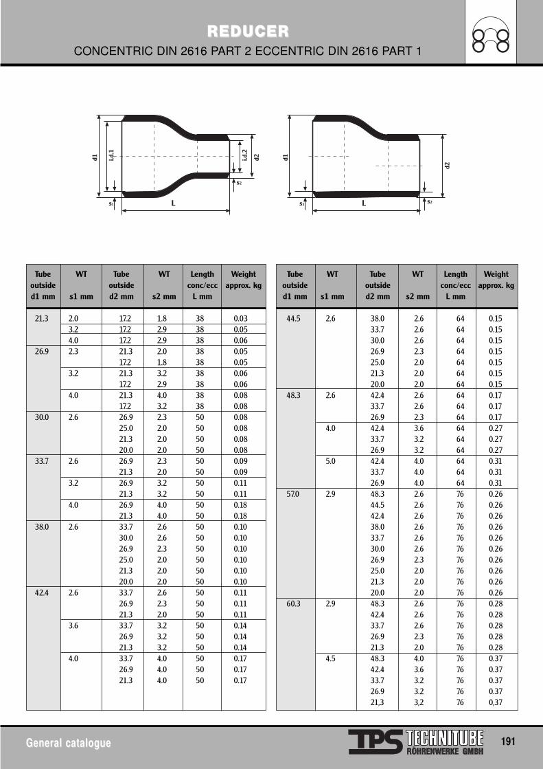
REDUCERREDUCERCONCENTRIC DIN 2616 PART 2 ECCENTRIC DIN 2616 PART 1
General catalogueGeneral catalogue 191
d1
L
d2
s1
i.d.1
i.d.2
s2
d1
L
d2
s1 s2
Tube WT Tube WT Length Weight Tube WT Tube WT Length Weightoutside outside conc/ecc approx. kg outside outside conc/ecc approx. kgd1 mm s1 mm d2 mm s2 mm L mm d1 mm s1 mm d2 mm s2 mm L mm
21.3 2.0 17.2 1.8 38 0.03 44.5 2.6 38.0 2.6 64 0.153.2 17.2 2.9 38 0.05 33.7 2.6 64 0.154.0 17.2 2.9 38 0.06 30.0 2.6 64 0.15
26.9 2.3 21.3 2.0 38 0.05 26.9 2.3 64 0.1517.2 1.8 38 0.05 25.0 2.0 64 0.15
3.2 21.3 3.2 38 0.06 21.3 2.0 64 0.1517.2 2.9 38 0.06 20.0 2.0 64 0.15
4.0 21.3 4.0 38 0.08 48.3 2.6 42.4 2.6 64 0.1717.2 3.2 38 0.08 33.7 2.6 64 0.17
30.0 2.6 26.9 2.3 50 0.08 26.9 2.3 64 0.1725.0 2.0 50 0.08 4.0 42.4 3.6 64 0.2721.3 2.0 50 0.08 33.7 3.2 64 0.2720.0 2.0 50 0.08 26.9 3.2 64 0.27
33.7 2.6 26.9 2.3 50 0.09 5.0 42.4 4.0 64 0.3121.3 2.0 50 0.09 33.7 4.0 64 0.31
3.2 26.9 3.2 50 0.11 26.9 4.0 64 0.3121.3 3.2 50 0.11 57.0 2.9 48.3 2.6 76 0.26
4.0 26.9 4.0 50 0.18 44.5 2.6 76 0.2621.3 4.0 50 0.18 42.4 2.6 76 0.26
38.0 2.6 33.7 2.6 50 0.10 38.0 2.6 76 0.2630.0 2.6 50 0.10 33.7 2.6 76 0.2626.9 2.3 50 0.10 30.0 2.6 76 0.2625.0 2.0 50 0.10 26.9 2.3 76 0.2621.3 2.0 50 0.10 25.0 2.0 76 0.2620.0 2.0 50 0.10 21.3 2.0 76 0.26
42.4 2.6 33.7 2.6 50 0.11 20.0 2.0 76 0.2626.9 2.3 50 0.11 60.3 2.9 48.3 2.6 76 0.2821.3 2.0 50 0.11 42.4 2.6 76 0.28
3.6 33.7 3.2 50 0.14 33.7 2.6 76 0.2826.9 3.2 50 0.14 26.9 2.3 76 0.2821.3 3.2 50 0.14 21.3 2.0 76 0.28
4.0 33.7 4.0 50 0.17 4.5 48.3 4.0 76 0.3726.9 4.0 50 0.17 42.4 3.6 76 0.3721.3 4.0 50 0.17 33.7 3.2 76 0.37
26.9 3.2 76 0.3721,3 3,2 76 0,37
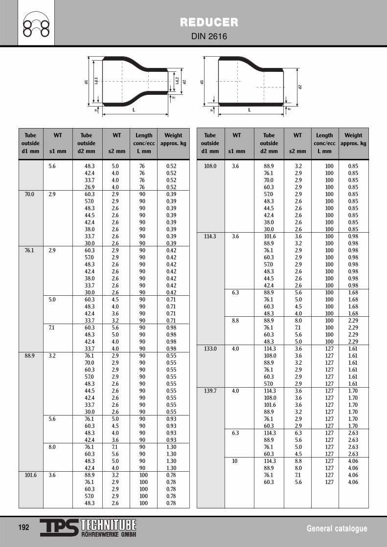
REDUCERREDUCERDIN 2616
192 General catalogueGeneral catalogue
d1
L
d2
s1
i.d.1
i.d.2
s2
d1
L
d2
s1 s2
Tube WT Tube WT Length Weight Tube WT Tube WT Length Weightoutside outside conc/ecc approx. kg outside outside conc/ecc approx. kgd1 mm s1 mm d2 mm s2 mm L mm d1 mm s1 mm d2 mm s2 mm L mm
5.6 48.3 5.0 76 0.52 108.0 3.6 88.9 3.2 100 0.8542.4 4.0 76 0.52 76.1 2.9 100 0.8533.7 4.0 76 0.52 70.0 2.9 100 0.8526.9 4.0 76 0.52 60.3 2.9 100 0.85
70.0 2.9 60.3 2.9 90 0.39 57.0 2.9 100 0.8557.0 2.9 90 0.39 48.3 2.6 100 0.8548.3 2.6 90 0.39 44.5 2.6 100 0.8544.5 2.6 90 0.39 42.4 2.6 100 0.8542.4 2.6 90 0.39 38.0 2.6 100 0.8538.0 2.6 90 0.39 30.0 2.6 100 0.8533.7 2.6 90 0.39 114.3 3.6 101.6 3.6 100 0.9830.0 2.6 90 0.39 88.9 3.2 100 0.98
76.1 2.9 60.3 2.9 90 0.42 76.1 2.9 100 0.9857.0 2.9 90 0.42 60.3 2.9 100 0.9848.3 2.6 90 0.42 57.0 2.9 100 0.9842.4 2.6 90 0.42 48.3 2.6 100 0.9838.0 2.6 90 0.42 44.5 2.6 100 0.9833.7 2.6 90 0.42 42.4 2.6 100 0.9830.0 2.6 90 0.42 6.3 88.9 5.6 100 1.68
5.0 60.3 4.5 90 0.71 76.1 5.0 100 1.6848.3 4.0 90 0.71 60.3 4.5 100 1.6842.4 3.6 90 0.71 48.3 4.0 100 1.6833.7 3.2 90 0.71 8.8 88.9 8.0 100 2.29
7.1 60.3 5.6 90 0.98 76.1 7.1 100 2.2948.3 5.0 90 0.98 60.3 5.6 100 2.2942.4 4.0 90 0.98 48.3 5.0 100 2.2933.7 4.0 90 0.98 133.0 4.0 114.3 3.6 127 1.61
88.9 3.2 76.1 2.9 90 0.55 108.0 3.6 127 1.6170.0 2.9 90 0.55 88.9 3.2 127 1.6160.3 2.9 90 0.55 76.1 2.9 127 1.6157.0 2.9 90 0.55 60.3 2.9 127 1.6148.3 2.6 90 0.55 57.0 2.9 127 1.6144.5 2.6 90 0.55 139.7 4.0 114.3 3.6 127 1.7042.4 2.6 90 0.55 108.0 3.6 127 1.7033.7 2.6 90 0.55 101.6 3.6 127 1.7030.0 2.6 90 0.55 88.9 3.2 127 1.70
5.6 76.1 5.0 90 0.93 76.1 2.9 127 1.7060.3 4.5 90 0.93 60.3 2.9 127 1.7048.3 4.0 90 0.93 6.3 114.3 6.3 127 2.6342.4 3.6 90 0.93 88.9 5.6 127 2.63
8.0 76.1 7.1 90 1.30 76.1 5.0 127 2.6360.3 5.6 90 1.30 60.3 4.5 127 2.6348.3 5.0 90 1.30 10 114.3 8.8 127 4.0642.4 4.0 90 1.30 88.9 8.0 127 4.06
101.6 3.6 88.9 3.2 100 0.78 76.1 7.1 127 4.0676.1 2.9 100 0.78 60.3 5.6 127 4.0660.3 2.9 100 0.7857.0 2.9 100 0.7848.3 2.6 100 0.78
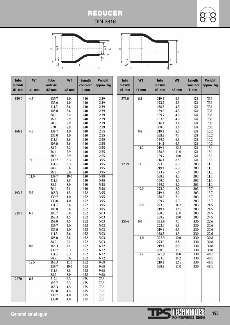
REDUCERREDUCERDIN 2616
General catalogueGeneral catalogue 193
d1
L
d2
s1
i.d.1
i.d.2
s2
d1
L
d2
s1 s2
Tube WT Tube WT Length Weight Tube WT Tube WT Length Weightoutside outside conc/ecc approx. kg outside outside conc/ecc approx. kgd1 mm s1 mm d2 mm s2 mm L mm d1 mm s1 mm d2 mm s2 mm L mm
159.0 4.5 139.7 4.0 140 2.39 273.0 6.3 219.1 6.3 178 7.36133.0 4.0 140 2.39 193.7 6.3 178 7.36114.3 3.6 140 2.39 168.3 4.5 178 7.36108.0 3.6 140 2.39 159.0 4.5 178 7.3688.9 3.2 140 2.39 139.7 4.0 178 7.3676.1 2.9 140 2.39 133.0 4.0 178 7.3660.3 2.9 140 2.39 114.3 3.6 178 7.3657.0 2.9 140 2.39 108.0 3.6 178 7.36
168.3 4.5 139.7 4.0 140 2.55 8.8 219.1 8.0 178 10.2133.0 4.0 140 2.55 168.3 7.1 178 10.2114.3 3.6 140 2.55 139.7 6.3 178 10.2108.0 3.6 140 2.55 114.3 6.3 178 10.288.9 3.2 140 2.55 14.2 219.1 12.5 178 16.176.1 2.9 140 2.55 168.3 11.0 178 16.160.3 2.9 140 2.55 139.7 10.0 178 16.1
7.1 139.7 6.3 140 3.95 114.3 8.8 178 16.1114.3 6.3 140 3.95 323.9 7.1 273.0 6.3 203 11.188.9 5.6 140 3.95 219.1 6.3 203 11.176.1 5.0 140 3.95 193.7 5.6 203 11.1
11.0 139.7 10.0 140 5.98 168.3 4.5 203 11.1114.3 8.8 140 5.98 159.0 4.5 203 11.188.9 8.0 140 5.98 139.7 4.0 203 11.176.1 7.1 140 5.98 10.0 273.0 8.0 203 15.7
193.7 5.6 168.3 4.5 152 3.95 219.1 8.0 203 15.7139.7 4.0 152 3.95 168.3 7.1 203 15.7133.0 4.0 152 3.95 139.7 6.3 203 15.7114.3 3.6 152 3.95 16.0 273.0 14.2 203 24.5108.0 3.6 152 3.95 219.1 12.5 203 24.5
219.1 6.3 193.7 5.6 152 5.03 168.3 11.0 203 24.5168.3 4.5 152 5.03 139.7 10.0 203 24.5159.0 4.5 152 5.03 355.6 8.0 323.9 7.1 330 22.6139.7 4.0 152 5.03 273.0 6.3 330 22.6133.0 4.0 152 5.03 219.1 6.3 330 22.6114.3 3.6 152 5.03 168.3 4.5 330 22.6108.0 3.6 152 5.03 11.0 323.9 10.0 330 30.888.9 3.2 152 5.03 273.0 8.8 330 30.8
8.0 168.3 7.1 152 6.32 219.1 8.0 330 30.8139.7 6.3 152 6.32 168.3 7.1 330 30.8114.3 6.3 152 6.32 17.5 323.9 16.0 330 48.188.9 5.6 152 6.32 273.0 14.2 330 48.1
12.5 168.3 11.0 152 9.68 219.1 12.5 330 48.1139.7 10.0 152 9.68 168.3 11.0 330 48.1114.3 8.8 152 9.6888.9 8.0 152 9.68
267.0 6.3 219.1 6.3 178 7.36193.7 6.3 178 7.36168.3 4.5 178 7.36159.0 4.5 178 7.36139.7 4.0 178 7.36133.0 4.0 178 7.36
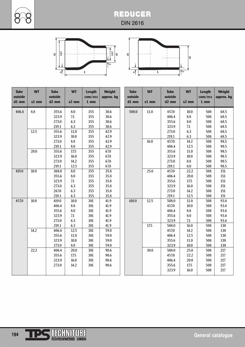
REDUCERREDUCERDIN 2616
194 General catalogueGeneral catalogue
d1
L
d2
s1
i.d.1
i.d.2
s2
d1
L
d2
s1 s2
Tube WT Tube WT Length Weight Tube WT Tube WT Length Weightoutside outside conc/ecc approx. kg outside outside conc/ecc approx. kgd1 mm s1 mm d2 mm s2 mm L mm d1 mm s1 mm d2 mm s2 mm L mm
406.4 8.8 355.6 8.0 355 30.6 508.0 11.0 457.0 10.0 508 68.5323.9 7.1 355 30.6 406.4 8.8 508 68.5273.0 6.3 355 30.6 355.6 8.0 508 68.5219.1 6.3 355 30.6 323.9 7.1 508 68.5
12.5 355.6 11.0 355 42.9 273.0 6.3 508 68.5323.9 10.0 355 42.9 219.1 6.3 508 68.5273.0 8.8 355 42.9 16.0 457.0 14.2 508 98.5219.1 8.0 355 42.9 406.4 12.5 508 98.5
20.0 355.6 17.5 355 67.8 355.6 11.0 508 98.5323.9 16.0 355 67.8 323.9 10.0 508 98.5273.0 14.2 355 67.8 273.0 8.8 508 98.5219.1 12.5 355 67.8 219.1 8.0 508 98.5
419.0 10.0 368.0 8.0 355 35.8 25.0 457.0 22.2 508 151355.6 8.0 355 35.8 406.4 20.0 508 151323.9 7.1 355 35.8 355.6 17.5 508 151273.0 6.3 355 35.8 323.9 16.0 508 151267.0 6.3 355 35.8 273.0 14.2 508 151219.1 6.3 355 35.8 219.1 12.5 508 151
457.0 10.0 419.0 10.0 381 41.9 610.0 12.5 508.0 11.0 508 93.4406.4 8.8 381 41.9 457.0 10.0 508 93.4355.6 8.0 381 41.9 406.4 8.8 508 93.4323.9 7.1 381 41.9 355.6 8.0 508 93.4273.0 6.3 381 41.9 323.9 7.1 508 93.4219.1 6.3 381 41.9 17.5 508.0 16.0 508 130
14.2 406.4 12.5 381 59.0 457.0 14.2 508 130355.6 11.0 381 59.0 406.4 12.5 508 130323.9 10.0 381 59.0 355.6 11.0 508 130273.0 8.8 381 59.0 323.9 10.0 508 130
22.2 406.4 20.0 381 90.6 30.0 508.0 25.0 508 217355.6 17.5 381 90.6 457.0 22.2 508 217323.9 16.0 381 90.6 406.4 20.0 508 217273.0 14.2 381 90.6 355.6 17.5 508 217
323.9 16.0 508 217
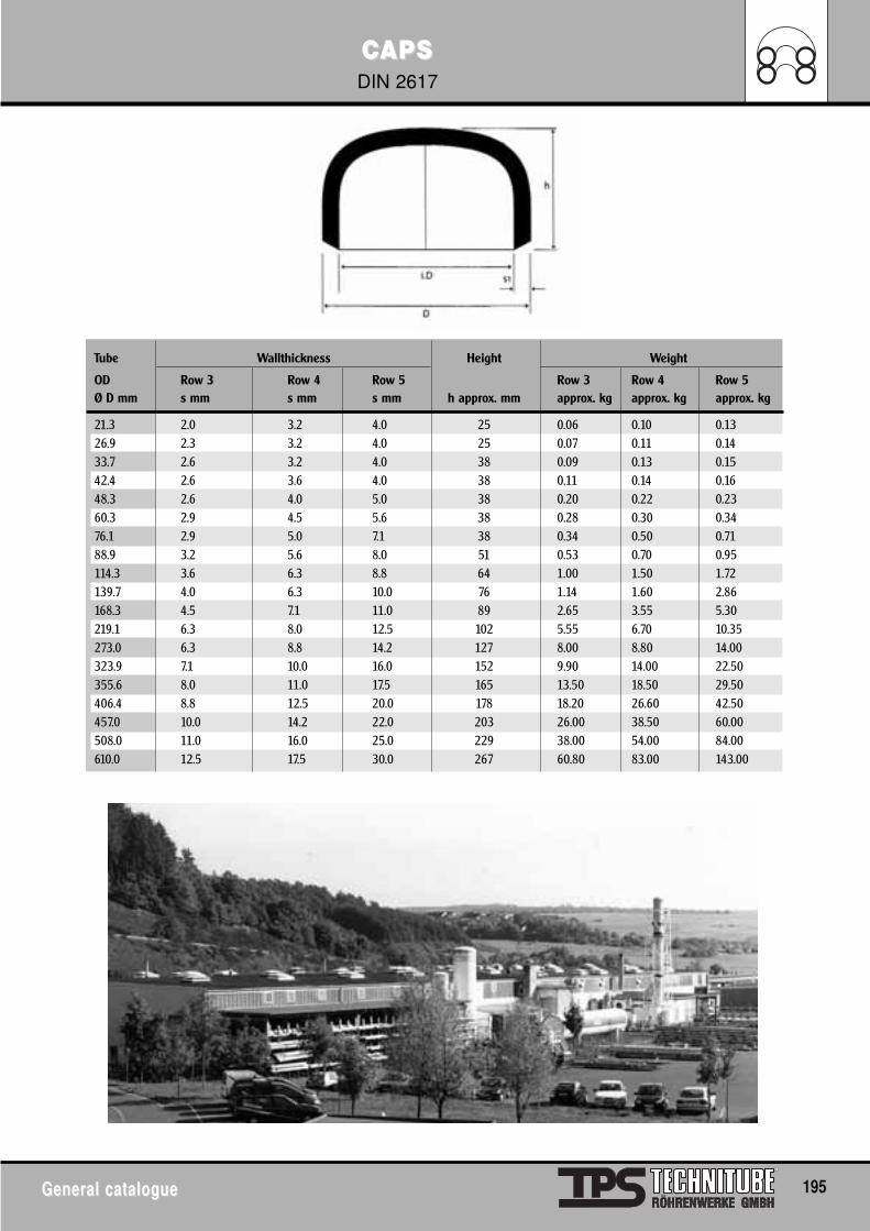
CCAPSAPSDIN 2617
General catalogueGeneral catalogue 195
Tube Wallthickness Height Weight
OD Row 3 Row 4 Row 5 Row 3 Row 4 Row 5Ø D mm s mm s mm s mm h approx. mm approx. kg approx. kg approx. kg
21.3 2.0 3.2 4.0 25 0.06 0.10 0.1326.9 2.3 3.2 4.0 25 0.07 0.11 0.1433.7 2.6 3.2 4.0 38 0.09 0.13 0.1542.4 2.6 3.6 4.0 38 0.11 0.14 0.1648.3 2.6 4.0 5.0 38 0.20 0.22 0.2360.3 2.9 4.5 5.6 38 0.28 0.30 0.3476.1 2.9 5.0 7.1 38 0.34 0.50 0.7188.9 3.2 5.6 8.0 51 0.53 0.70 0.95114.3 3.6 6.3 8.8 64 1.00 1.50 1.72139.7 4.0 6.3 10.0 76 1.14 1.60 2.86168.3 4.5 7.1 11.0 89 2.65 3.55 5.30219.1 6.3 8.0 12.5 102 5.55 6.70 10.35273.0 6.3 8.8 14.2 127 8.00 8.80 14.00323.9 7.1 10.0 16.0 152 9.90 14.00 22.50355.6 8.0 11.0 17.5 165 13.50 18.50 29.50406.4 8.8 12.5 20.0 178 18.20 26.60 42.50457.0 10.0 14.2 22.0 203 26.00 38.50 60.00508.0 11.0 16.0 25.0 229 38.00 54.00 84.00610.0 12.5 17.5 30.0 267 60.80 83.00 143.00
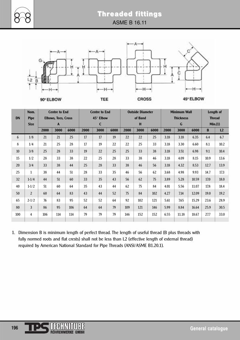
ThrThreaded feaded f ittingsittingsASME B 16.11
196 General catalogueGeneral catalogue
Nom. Centre to End Centre to End Outside Diameter Minimum Wall Length of
DN Pipe Elbows, Tees, Cross 45° Elbow of Band Thickness Thread
Size A C H G Min.(1)
2000 3000 6000 2000 3000 6000 2000 3000 6000 2000 3000 6000 B L2
6 1/8 21 21 25 17 17 19 22 22 25 3.18 3.18 6.35 6.4 6.7
8 1/4 21 25 28 17 19 22 22 25 33 3.18 3.30 6.60 8.1 10.2
10 3/8 25 28 33 19 22 25 25 33 38 3.18 3.51 6.98 9.1 10.4
15 1/2 28 33 38 22 25 28 33 38 46 3.18 4.09 8.15 10.9 13.6
20 3/4 33 38 44 25 28 33 38 46 56 3.18 4.32 8.53 12.7 13.9
25 1 38 44 51 28 33 35 46 56 62 3.68 4.98 9.93 14.7 17.3
32 1-1/4 44 51 60 33 35 43 56 62 75 3.89 5.28 10.59 17.0 18.0
40 1-1/2 51 60 64 35 43 44 62 75 84 4.01 5.56 11.07 17.8 18.4
50 2 60 64 83 43 44 52 75 84 102 4.27 7.14 12.09 19.0 19.2
65 2-1/2 76 83 95 52 52 64 92 102 121 5.61 7.65 15.29 23.6 28.9
80 3 86 95 106 64 64 79 109 121 146 5.99 8.84 16.64 25.9 30.5
100 4 106 114 114 79 79 79 146 152 152 6.55 11.18 18.67 27.7 33.0
1. Dimension B is minimum length of perfect thread. The length of useful thread (B plus threads withfully normed roots and flat crests) shall not be less than L2 (effective length of external thread)required by American National Standard for Pipe Threads (ANSI/ASME B1.20.1).
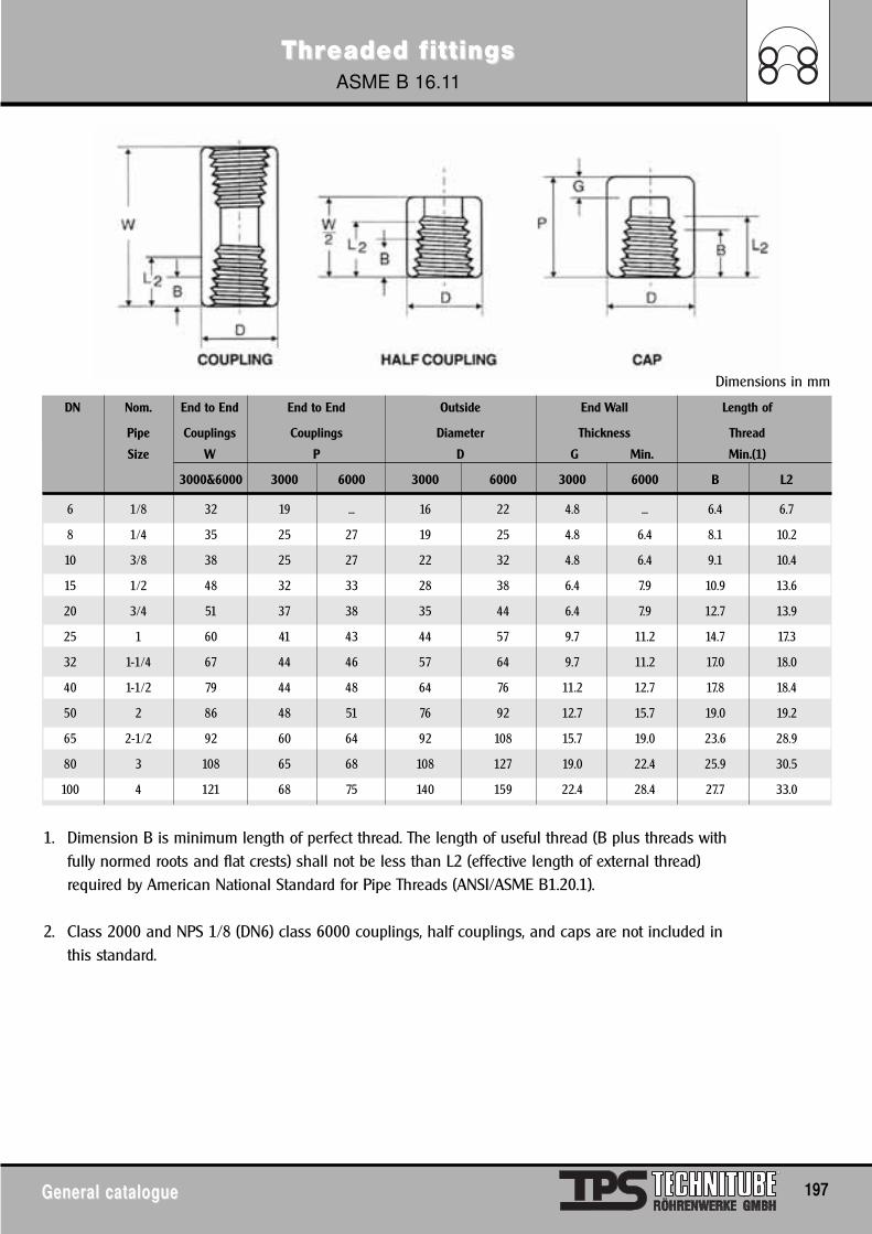
ThrThreaded feaded f ittingsittingsASME B 16.11
General catalogueGeneral catalogue 197
DN Nom. End to End End to End Outside End Wall Length of
Pipe Couplings Couplings Diameter Thickness Thread
Size W P D G Min. Min.(1)
3000&6000 3000 6000 3000 6000 3000 6000 B L2
6 1/8 32 19 ... 16 22 4.8 ... 6.4 6.7
8 1/4 35 25 27 19 25 4.8 6.4 8.1 10.2
10 3/8 38 25 27 22 32 4.8 6.4 9.1 10.4
15 1/2 48 32 33 28 38 6.4 7.9 10.9 13.6
20 3/4 51 37 38 35 44 6.4 7.9 12.7 13.9
25 1 60 41 43 44 57 9.7 11.2 14.7 17.3
32 1-1/4 67 44 46 57 64 9.7 11.2 17.0 18.0
40 1-1/2 79 44 48 64 76 11.2 12.7 17.8 18.4
50 2 86 48 51 76 92 12.7 15.7 19.0 19.2
65 2-1/2 92 60 64 92 108 15.7 19.0 23.6 28.9
80 3 108 65 68 108 127 19.0 22.4 25.9 30.5
100 4 121 68 75 140 159 22.4 28.4 27.7 33.0
1. Dimension B is minimum length of perfect thread. The length of useful thread (B plus threads withfully normed roots and flat crests) shall not be less than L2 (effective length of external thread)required by American National Standard for Pipe Threads (ANSI/ASME B1.20.1).
2. Class 2000 and NPS 1/8 (DN6) class 6000 couplings, half couplings, and caps are not included inthis standard.
Dimensions in mm
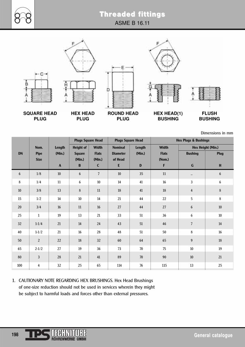
ThrThreaded feaded f ittingsittingsASME B 16.11
198 General catalogueGeneral catalogue
Plugs Square Head Plugs Square Head Hex Plugs & Bushings
Nom. Length Height of Width Nominal Length Width Hex Height (Min.)
DN Pipe (Min.) Square Flats Diameter (Min.) Flats Bushing Plug
Size (Min.) (Min.) of Head (Nom.)
A B C E D F G H
6 1/8 10 6 7 10 35 11 ... 6
8 1/4 11 6 10 14 41 16 3 6
10 3/8 13 8 11 18 41 18 4 8
15 1/2 14 10 14 21 44 22 5 8
20 3/4 16 11 16 27 44 27 6 10
25 1 19 13 21 33 51 36 6 10
32 1-1/4 21 14 24 43 51 46 7 14
40 1-1/2 21 16 28 48 51 50 8 16
50 2 22 18 32 60 64 65 9 18
65 2-1/2 27 19 36 73 70 75 10 19
80 3 28 21 41 89 70 90 10 21
100 4 32 25 65 114 76 115 13 25
1. CAUTIONARY NOTE REGARDING HEX BRUSHINGS. Hex Head Brushingsof one-size reduction should not be used in services wherein they mightbe subject to harmful loads and forces other than external pressures.
Dimensions in mm
SQUARE HEAD HEX HEAD ROUND HEAD HEX HEAD(1) FLUSHPLUG PLUG PLUG BUSHING BUSHING
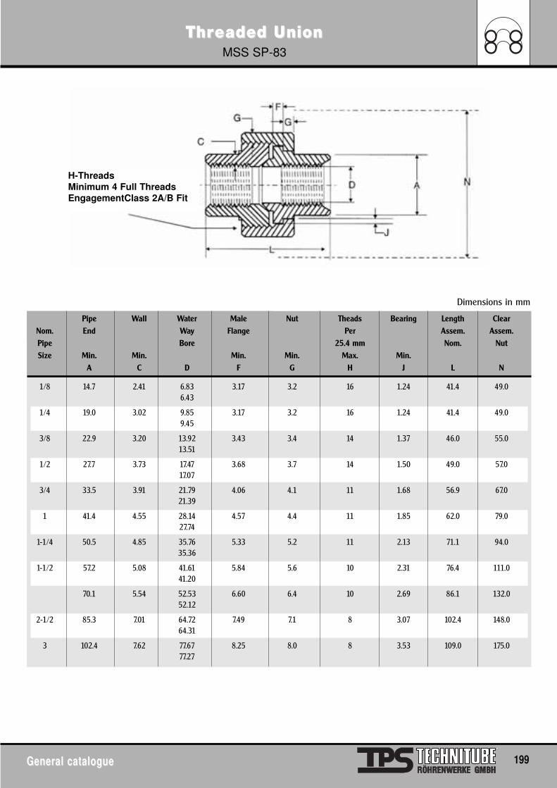
ThrThreaded Ueaded UnionnionMSS SP-83
General catalogueGeneral catalogue 199
Pipe Wall Water Male Nut Theads Bearing Length ClearNom. End Way Flange Per Assem. Assem.Pipe Bore 25.4 mm Nom. NutSize Min. Min. Min. Min. Max. Min.
A C D F G H J L N
1/8 14.7 2.41 6.83 3.17 3.2 16 1.24 41.4 49.06.43
1/4 19.0 3.02 9.85 3.17 3.2 16 1.24 41.4 49.09.45
3/8 22.9 3.20 13.92 3.43 3.4 14 1.37 46.0 55.013.51
1/2 27.7 3.73 17.47 3.68 3.7 14 1.50 49.0 57.017.07
3/4 33.5 3.91 21.79 4.06 4.1 11 1.68 56.9 67.021.39
1 41.4 4.55 28.14 4.57 4.4 11 1.85 62.0 79.027.74
1-1/4 50.5 4.85 35.76 5.33 5.2 11 2.13 71.1 94.035.36
1-1/2 57.2 5.08 41.61 5.84 5.6 10 2.31 76.4 111.041.20
70.1 5.54 52.53 6.60 6.4 10 2.69 86.1 132.052.12
2-1/2 85.3 7.01 64.72 7.49 7.1 8 3.07 102.4 148.064.31
3 102.4 7.62 77.67 8.25 8.0 8 3.53 109.0 175.077.27
Dimensions in mm
H-ThreadsMinimum 4 Full ThreadsEngagementClass 2A/B Fit
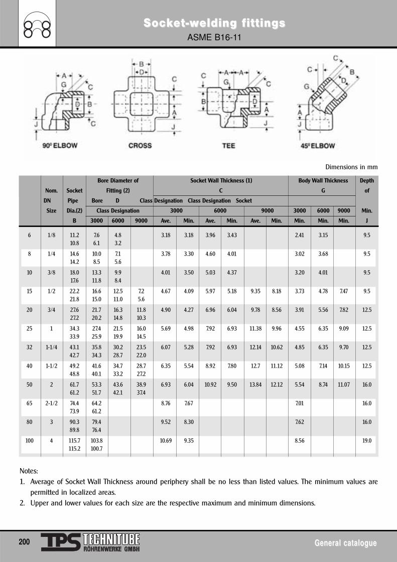
SocSockkeet-wt-welding felding f ittingsittingsASME B16-11
200 General catalogueGeneral catalogue
Dimensions in mm
Bore Diameter of Socket Wall Thickness (1) Body Wall Thickness Depth
Nom. Socket Fitting (2) C G of
DN Pipe Bore D Class Designation Class Designation Socket
Size Dia.(2) Class Designation 3000 6000 9000 3000 6000 9000 Min.
B 3000 6000 9000 Ave. Min. Ave. Min. Ave. Min. Min. Min. Min. J
6 1/8 11.2 7.6 4.8 3.18 3.18 3.96 3.43 2.41 3.15 9.510.8 6.1 3.2
8 1/4 14.6 10.0 7.1 3.78 3.30 4.60 4.01 3.02 3.68 9.514.2 8.5 5.6
10 3/8 18.0 13.3 9.9 4.01 3.50 5.03 4.37 3.20 4.01 9.517.6 11.8 8.4
15 1/2 22.2 16.6 12.5 7.2 4.67 4.09 5.97 5.18 9.35 8.18 3.73 4.78 7.47 9.521.8 15.0 11.0 5.6
20 3/4 27.6 21.7 16.3 11.8 4.90 4.27 6.96 6.04 9.78 8.56 3.91 5.56 7.82 12.527.2 20.2 14.8 10.3
25 1 34.3 27.4 21.5 16.0 5.69 4.98 7.92 6.93 11.38 9.96 4.55 6.35 9.09 12.533.9 25.9 19.9 14.5
32 1-1/4 43.1 35.8 30.2 23.5 6.07 5.28 7.92 6.93 12.14 10.62 4.85 6.35 9.70 12.542.7 34.3 28.7 22.0
40 1-1/2 49.2 41.6 34.7 28.7 6.35 5.54 8.92 7.80 12.7 11.12 5.08 7.14 10.15 12.548.8 40.1 33.2 27.2
50 2 61.7 53.3 43.6 38.9 6.93 6.04 10.92 9.50 13.84 12.12 5.54 8.74 11.07 16.061.2 51.7 42.1 37.4
65 2-1/2 74.4 64.2 8.76 7.67 7.01 16.073.9 61.2
80 3 90.3 79.4 9.52 8.30 7.62 16.089.8 76.4
100 4 115.7 103.8 10.69 9.35 8.56 19.0115.2 100.7
Notes:1. Average of Socket Wall Thickness around periphery shall be no less than listed values. The minimum values are
permitted in localized areas.2. Upper and lower values for each size are the respective maximum and minimum dimensions.
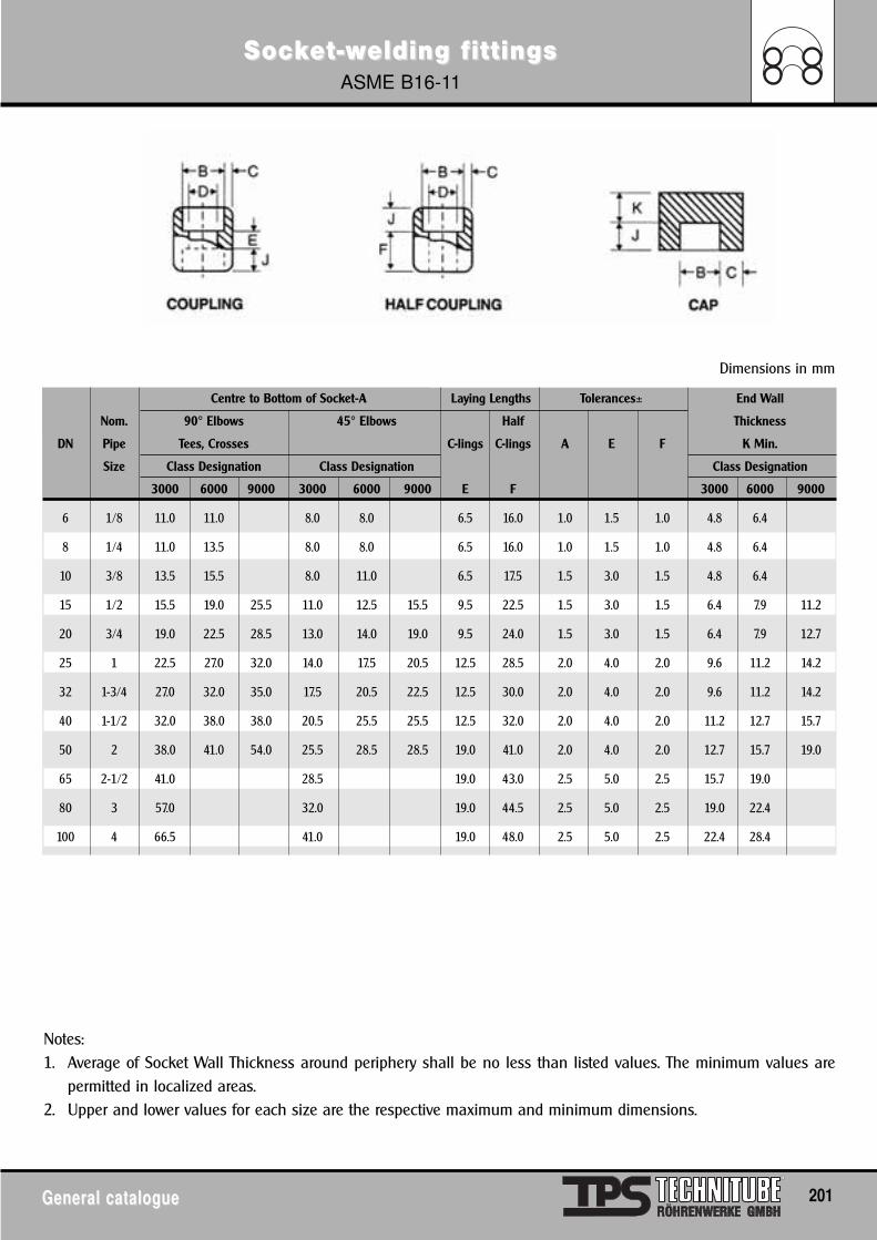
SocSockkeet-wt-welding felding f ittingsittingsASME B16-11
General catalogueGeneral catalogue 201
Dimensions in mm
Centre to Bottom of Socket-A Laying Lengths Tolerances± End Wall
Nom. 90° Elbows 45° Elbows Half Thickness
DN Pipe Tees, Crosses C-lings C-lings A E F K Min.
Size Class Designation Class Designation Class Designation
3000 6000 9000 3000 6000 9000 E F 3000 6000 9000
6 1/8 11.0 11.0 8.0 8.0 6.5 16.0 1.0 1.5 1.0 4.8 6.4
8 1/4 11.0 13.5 8.0 8.0 6.5 16.0 1.0 1.5 1.0 4.8 6.4
10 3/8 13.5 15.5 8.0 11.0 6.5 17.5 1.5 3.0 1.5 4.8 6.4
15 1/2 15.5 19.0 25.5 11.0 12.5 15.5 9.5 22.5 1.5 3.0 1.5 6.4 7.9 11.2
20 3/4 19.0 22.5 28.5 13.0 14.0 19.0 9.5 24.0 1.5 3.0 1.5 6.4 7.9 12.7
25 1 22.5 27.0 32.0 14.0 17.5 20.5 12.5 28.5 2.0 4.0 2.0 9.6 11.2 14.2
32 1-3/4 27.0 32.0 35.0 17.5 20.5 22.5 12.5 30.0 2.0 4.0 2.0 9.6 11.2 14.2
40 1-1/2 32.0 38.0 38.0 20.5 25.5 25.5 12.5 32.0 2.0 4.0 2.0 11.2 12.7 15.7
50 2 38.0 41.0 54.0 25.5 28.5 28.5 19.0 41.0 2.0 4.0 2.0 12.7 15.7 19.0
65 2-1/2 41.0 28.5 19.0 43.0 2.5 5.0 2.5 15.7 19.0
80 3 57.0 32.0 19.0 44.5 2.5 5.0 2.5 19.0 22.4
100 4 66.5 41.0 19.0 48.0 2.5 5.0 2.5 22.4 28.4
Notes:1. Average of Socket Wall Thickness around periphery shall be no less than listed values. The minimum values are
permitted in localized areas.2. Upper and lower values for each size are the respective maximum and minimum dimensions.
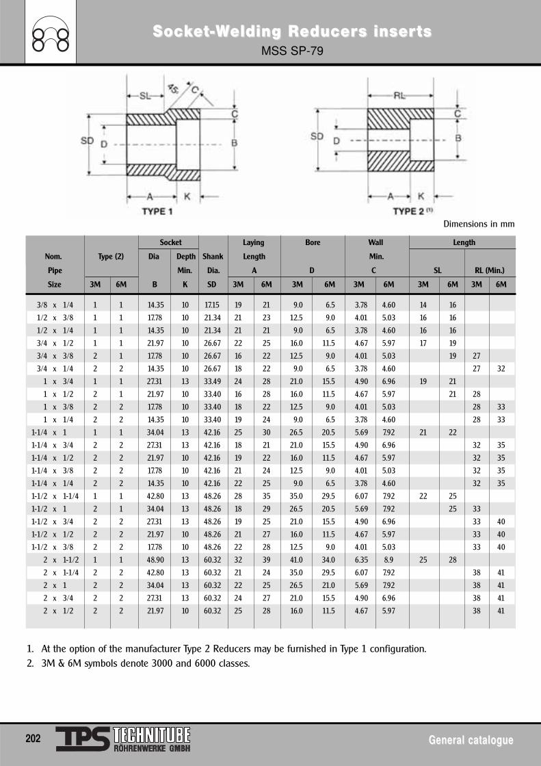
SocSockkeet-t-WWelding Relding Reducereducers insers inserts ts MSS SP-79
202 General catalogueGeneral catalogue
Dimensions in mm
Socket Laying Bore Wall Length
Nom. Type (2) Dia Depth Shank Length Min.
Pipe Min. Dia. A D C SL RL (Min.)
Size 3M 6M B K SD 3M 6M 3M 6M 3M 6M 3M 6M 3M 6M
3/8 x 1/4 1 1 14.35 10 17.15 19 21 9.0 6.5 3.78 4.60 14 16
1/2 x 3/8 1 1 17.78 10 21.34 21 23 12.5 9.0 4.01 5.03 16 16
1/2 x 1/4 1 1 14.35 10 21.34 21 21 9.0 6.5 3.78 4.60 16 16
3/4 x 1/2 1 1 21.97 10 26.67 22 25 16.0 11.5 4.67 5.97 17 19
3/4 x 3/8 2 1 17.78 10 26.67 16 22 12.5 9.0 4.01 5.03 19 27
3/4 x 1/4 2 2 14.35 10 26.67 18 22 9.0 6.5 3.78 4.60 27 32
1 x 3/4 1 1 27.31 13 33.49 24 28 21.0 15.5 4.90 6.96 19 21
1 x 1/2 2 1 21.97 10 33.40 16 28 16.0 11.5 4.67 5.97 21 28
1 x 3/8 2 2 17.78 10 33.40 18 22 12.5 9.0 4.01 5.03 28 33
1 x 1/4 2 2 14.35 10 33.40 19 24 9.0 6.5 3.78 4.60 28 33
1-1/4 x 1 1 1 34.04 13 42.16 25 30 26.5 20.5 5.69 7.92 21 22
1-1/4 x 3/4 2 2 27.31 13 42.16 18 21 21.0 15.5 4.90 6.96 32 35
1-1/4 x 1/2 2 2 21.97 10 42.16 19 22 16.0 11.5 4.67 5.97 32 35
1-1/4 x 3/8 2 2 17.78 10 42.16 21 24 12.5 9.0 4.01 5.03 32 35
1-1/4 x 1/4 2 2 14.35 10 42.16 22 25 9.0 6.5 3.78 4.60 32 35
1-1/2 x 1-1/4 1 1 42.80 13 48.26 28 35 35.0 29.5 6.07 7.92 22 25
1-1/2 x 1 2 1 34.04 13 48.26 18 29 26.5 20.5 5.69 7.92 25 33
1-1/2 x 3/4 2 2 27.31 13 48.26 19 25 21.0 15.5 4.90 6.96 33 40
1-1/2 x 1/2 2 2 21.97 10 48.26 21 27 16.0 11.5 4.67 5.97 33 40
1-1/2 x 3/8 2 2 17.78 10 48.26 22 28 12.5 9.0 4.01 5.03 33 40
2 x 1-1/2 1 1 48.90 13 60.32 32 39 41.0 34.0 6.35 8.9 25 28
2 x 1-1/4 2 2 42.80 13 60.32 21 24 35.0 29.5 6.07 7.92 38 41
2 x 1 2 2 34.04 13 60.32 22 25 26.5 21.0 5.69 7.92 38 41
2 x 3/4 2 2 27.31 13 60.32 24 27 21.0 15.5 4.90 6.96 38 41
2 x 1/2 2 2 21.97 10 60.32 25 28 16.0 11.5 4.67 5.97 38 41
1. At the option of the manufacturer Type 2 Reducers may be furnished in Type 1 configuration.2. 3M & 6M symbols denote 3000 and 6000 classes.
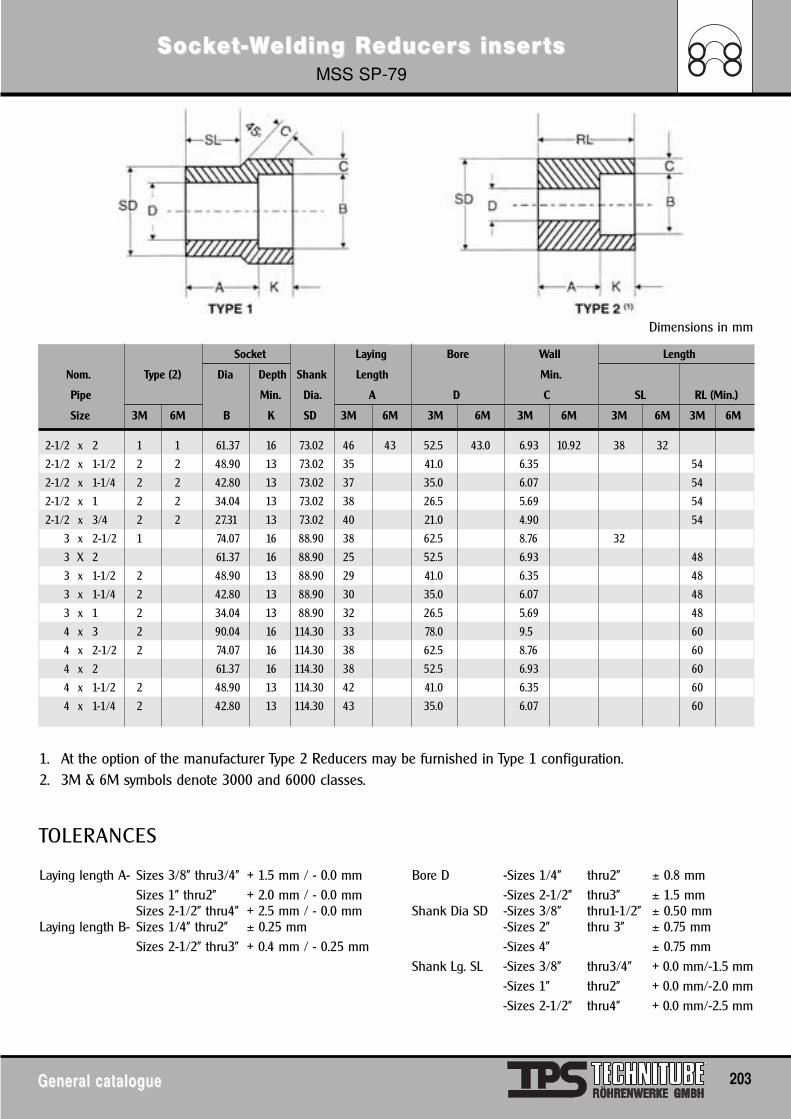
SocSockkeet-t-WWelding Relding Reducereducers insers inserts ts MSS SP-79
General catalogueGeneral catalogue 203
Dimensions in mm
Socket Laying Bore Wall Length
Nom. Type (2) Dia Depth Shank Length Min.
Pipe Min. Dia. A D C SL RL (Min.)
Size 3M 6M B K SD 3M 6M 3M 6M 3M 6M 3M 6M 3M 6M
2-1/2 x 2 1 1 61.37 16 73.02 46 43 52.5 43.0 6.93 10.92 38 32
2-1/2 x 1-1/2 2 2 48.90 13 73.02 35 41.0 6.35 54
2-1/2 x 1-1/4 2 2 42.80 13 73.02 37 35.0 6.07 54
2-1/2 x 1 2 2 34.04 13 73.02 38 26.5 5.69 54
2-1/2 x 3/4 2 2 27.31 13 73.02 40 21.0 4.90 54
3 x 2-1/2 1 74.07 16 88.90 38 62.5 8.76 32
3 X 2 61.37 16 88.90 25 52.5 6.93 48
3 x 1-1/2 2 48.90 13 88.90 29 41.0 6.35 48
3 x 1-1/4 2 42.80 13 88.90 30 35.0 6.07 48
3 x 1 2 34.04 13 88.90 32 26.5 5.69 48
4 x 3 2 90.04 16 114.30 33 78.0 9.5 60
4 x 2-1/2 2 74.07 16 114.30 38 62.5 8.76 60
4 x 2 61.37 16 114.30 38 52.5 6.93 60
4 x 1-1/2 2 48.90 13 114.30 42 41.0 6.35 60
4 x 1-1/4 2 42.80 13 114.30 43 35.0 6.07 60
1. At the option of the manufacturer Type 2 Reducers may be furnished in Type 1 configuration.2. 3M & 6M symbols denote 3000 and 6000 classes.
TOLERANCES
Laying length A- Sizes 3/8" thru3/4" + 1.5 mm / - 0.0 mm Bore D -Sizes 1/4" thru2" ± 0.8 mmSizes 1" thru2" + 2.0 mm / - 0.0 mm -Sizes 2-1/2" thru3" ± 1.5 mmSizes 2-1/2" thru4" + 2.5 mm / - 0.0 mm Shank Dia SD -Sizes 3/8" thru1-1/2" ± 0.50 mm
Laying length B- Sizes 1/4" thru2" ± 0.25 mm -Sizes 2" thru 3" ± 0.75 mmSizes 2-1/2" thru3" + 0.4 mm / - 0.25 mm -Sizes 4" ± 0.75 mm
Shank Lg. SL -Sizes 3/8" thru3/4" + 0.0 mm/-1.5 mm-Sizes 1" thru2" + 0.0 mm/-2.0 mm-Sizes 2-1/2" thru4" + 0.0 mm/-2.5 mm
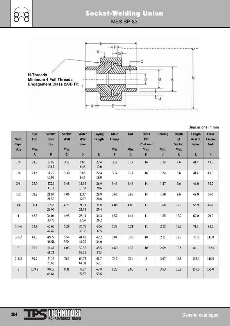
SocSockkeet-t-WWelding Uelding UnionnionMSS SP-83
204 General catalogueGeneral catalogue
Pipe Socket Socket Water Laying Male Nut Thrds Bearing Depth Length ClearNom. End Bore Wall Way Length Flange Per of Assem. Assem.Pipe Dia Bore 25.4 mm Socket Nom. NutSize Min. Min. Min. Min. Max. Min. Min.
A B C D E F G H J K L N
1/8 21.8 10.92 3.17 6.83 22.4 3.17 3.17 16 1.24 9.6 41.4 49.010.67 6.43 19.0
1/4 21.8 14.22 3.30 9.85 22.4 3.17 3.17 16 1.24 9.6 41.4 49.013.97 9.45 19.0
3/8 25.9 17.78 3.48 13.92 26.9 3.43 3.43 14 1.37 9.6 46.0 55.017.53 13.51 20.6
1/2 31.2 21.84 4.06 17.47 26.9 3.68 3.68 14 1.50 9.6 49.0 57.021.59 17.07 20.6
3/4 37.1 27.18 4.27 21.79 31.8 4.06 4.06 11 1.68 12.7 56.9 67.026.92 21.39 25.4
1 45.5 34.04 4.95 28.14 34.3 4.57 4.44 11 1.85 12.7 62.0 79.033.78 27.74 26.2
1-1/4 54.9 42.67 5.28 35.76 4.06 5.33 5.21 11 2.13 12.7 71.1 94.042.42 35.36 32.5
1-1/2 61.5 48.77 5.54 41.61 42.2 5.84 5.59 10 2.31 12.7 76.5 111.048.51 5.54 41.20 34.0
2 75.2 61.47 6.05 52.53 45.5 6.60 6.35 10 2.69 15.8 86.1 132.061.21 52.12 37.3
2-1/2 91.7 74.17 7.65 64.72 61.7 7.49 7.11 8 3.07 15.8 102.4 148.073.66 64.31 52.1
3 109.2 90.17 8.31 77.67 63.8 8.25 8.00 8 3.53 15.8 109.0 175.089.66 77.27 53.6
Dimensions in mm
H-ThreadsMinimum 4 Full ThreadsEngagement Class 2A/B Fit
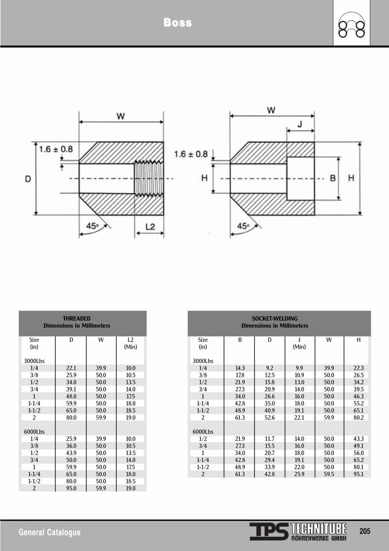
BossBoss
General CatalogueGeneral Catalogue 205
THREADED SOCKET-WELDINGDimensions in Millimeters Dimensions in Millimeters
Size D W L2 Size B D J W H(in) (Min) (in) (Min)
3000Lbs 3000Lbs1/4 22.1 39.9 10.0 1/4 14.3 9.2 9.9 39.9 22.33/8 25.9 50.0 10.5 3/8 17.8 12.5 10.9 50.0 26.51/2 34.0 50.0 13.5 1/2 21.9 15.8 13.0 50.0 34.23/4 39.1 50.0 14.0 3/4 27.3 20.9 14.0 50.0 39.51 48.0 50.0 17.5 1 34.0 26.6 16.0 50.0 46.3
1-1/4 59.9 50.0 18.0 1-1/4 42.8 35.0 18.0 50.0 55.21-1/2 65.0 50.0 18.5 1-1/2 48.9 40.9 19.1 50.0 65.1
2 80.0 59.9 19.0 2 61.3 52.6 22.1 59.9 80.2
6000Lbs 6000Lbs1/4 25.9 39.9 10.0 1/2 21.9 11.7 14.0 50.0 43.33/8 36.0 50.0 10.5 3/4 27.3 15.5 16.0 50.0 49.11/2 43.9 50.0 13.5 1 34.0 20.7 18.0 50.0 56.03/4 50.0 50.0 14.0 1-1/4 42.8 29.4 19.1 50.0 65.21 59.9 50.0 17.5 1-1/2 48.9 33.9 22.0 50.0 80.1
1-1/4 65.0 50.0 18.0 2 61.3 42.8 25.9 59.5 95.11-1/2 80.0 50.0 18.5
2 95.0 59.9 19.0
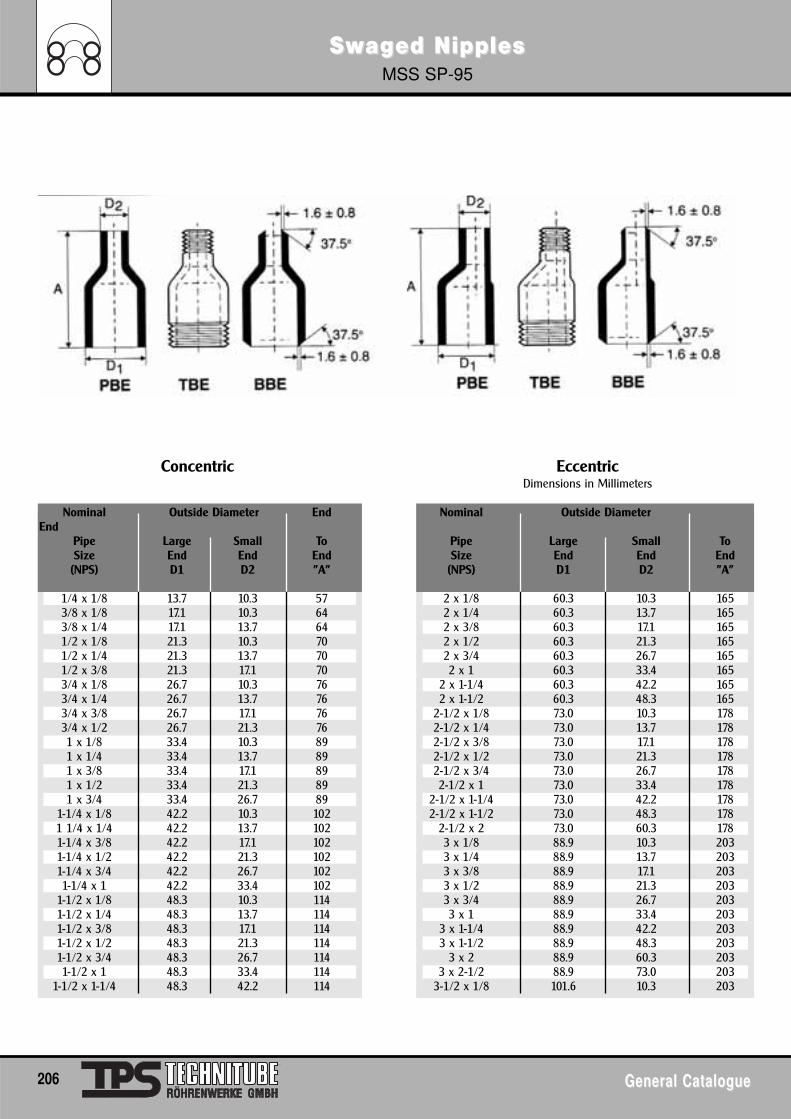
SwSwagaged Nipplesed NipplesMSS SP-95
206 General CatalogueGeneral Catalogue
Concentric Eccentric Dimensions in Millimeters
Nominal Outside Diameter End Nominal Outside DiameterEnd
Pipe Large Small To Pipe Large Small ToSize End End End Size End End End(NPS) D1 D2 "A" (NPS) D1 D2 "A"
1/4 x 1/8 13.7 10.3 57 2 x 1/8 60.3 10.3 1653/8 x 1/8 17.1 10.3 64 2 x 1/4 60.3 13.7 1653/8 x 1/4 17.1 13.7 64 2 x 3/8 60.3 17.1 1651/2 x 1/8 21.3 10.3 70 2 x 1/2 60.3 21.3 1651/2 x 1/4 21.3 13.7 70 2 x 3/4 60.3 26.7 1651/2 x 3/8 21.3 17.1 70 2 x 1 60.3 33.4 1653/4 x 1/8 26.7 10.3 76 2 x 1-1/4 60.3 42.2 1653/4 x 1/4 26.7 13.7 76 2 x 1-1/2 60.3 48.3 1653/4 x 3/8 26.7 17.1 76 2-1/2 x 1/8 73.0 10.3 1783/4 x 1/2 26.7 21.3 76 2-1/2 x 1/4 73.0 13.7 1781 x 1/8 33.4 10.3 89 2-1/2 x 3/8 73.0 17.1 1781 x 1/4 33.4 13.7 89 2-1/2 x 1/2 73.0 21.3 1781 x 3/8 33.4 17.1 89 2-1/2 x 3/4 73.0 26.7 1781 x 1/2 33.4 21.3 89 2-1/2 x 1 73.0 33.4 1781 x 3/4 33.4 26.7 89 2-1/2 x 1-1/4 73.0 42.2 178
1-1/4 x 1/8 42.2 10.3 102 2-1/2 x 1-1/2 73.0 48.3 1781 1/4 x 1/4 42.2 13.7 102 2-1/2 x 2 73.0 60.3 1781-1/4 x 3/8 42.2 17.1 102 3 x 1/8 88.9 10.3 2031-1/4 x 1/2 42.2 21.3 102 3 x 1/4 88.9 13.7 2031-1/4 x 3/4 42.2 26.7 102 3 x 3/8 88.9 17.1 2031-1/4 x 1 42.2 33.4 102 3 x 1/2 88.9 21.3 203
1-1/2 x 1/8 48.3 10.3 114 3 x 3/4 88.9 26.7 2031-1/2 x 1/4 48.3 13.7 114 3 x 1 88.9 33.4 2031-1/2 x 3/8 48.3 17.1 114 3 x 1-1/4 88.9 42.2 2031-1/2 x 1/2 48.3 21.3 114 3 x 1-1/2 88.9 48.3 2031-1/2 x 3/4 48.3 26.7 114 3 x 2 88.9 60.3 2031-1/2 x 1 48.3 33.4 114 3 x 2-1/2 88.9 73.0 203
1-1/2 x 1-1/4 48.3 42.2 114 3-1/2 x 1/8 101.6 10.3 203
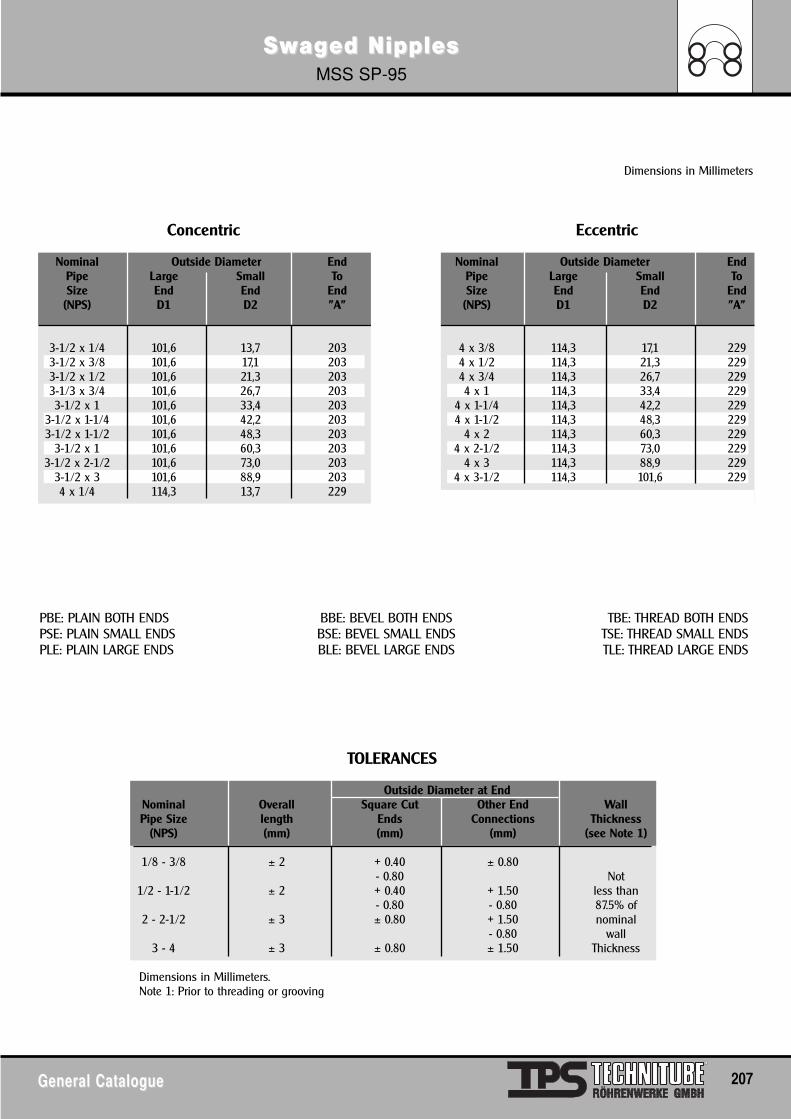
SwSwagaged Nipplesed NipplesMSS SP-95
General CatalogueGeneral Catalogue 207
PBE: PLAIN BOTH ENDS BBE: BEVEL BOTH ENDS TBE: THREAD BOTH ENDSPSE: PLAIN SMALL ENDS BSE: BEVEL SMALL ENDS TSE: THREAD SMALL ENDSPLE: PLAIN LARGE ENDS BLE: BEVEL LARGE ENDS TLE: THREAD LARGE ENDS
Dimensions in Millimeters
Concentric Eccentric
Nominal Outside Diameter End Nominal Outside Diameter EndPipe Large Small To Pipe Large Small ToSize End End End Size End End End(NPS) D1 D2 "A" (NPS) D1 D2 "A"
3-1/2 x 1/4 101,6 13,7 203 4 x 3/8 114,3 17,1 2293-1/2 x 3/8 101,6 17,1 203 4 x 1/2 114,3 21,3 2293-1/2 x 1/2 101,6 21,3 203 4 x 3/4 114,3 26,7 2293-1/3 x 3/4 101,6 26,7 203 4 x 1 114,3 33,4 2293-1/2 x 1 101,6 33,4 203 4 x 1-1/4 114,3 42,2 229
3-1/2 x 1-1/4 101,6 42,2 203 4 x 1-1/2 114,3 48,3 2293-1/2 x 1-1/2 101,6 48,3 203 4 x 2 114,3 60,3 229
3-1/2 x 1 101,6 60,3 203 4 x 2-1/2 114,3 73,0 2293-1/2 x 2-1/2 101,6 73,0 203 4 x 3 114,3 88,9 229
3-1/2 x 3 101,6 88,9 203 4 x 3-1/2 114,3 101,6 2294 x 1/4 114,3 13,7 229
TOLERANCES
Outside Diameter at EndNominal Overall Square Cut Other End WallPipe Size length Ends Connections Thickness
(NPS) (mm) (mm) (mm) (see Note 1)
1/8 - 3/8 ± 2 + 0.40 ± 0.80- 0.80 Not
1/2 - 1-1/2 ± 2 + 0.40 + 1.50 less than- 0.80 - 0.80 87.5% of
2 - 2-1/2 ± 3 ± 0.80 + 1.50 nominal- 0.80 wall
3 - 4 ± 3 ± 0.80 ± 1.50 Thickness
Dimensions in Millimeters.Note 1: Prior to threading or grooving
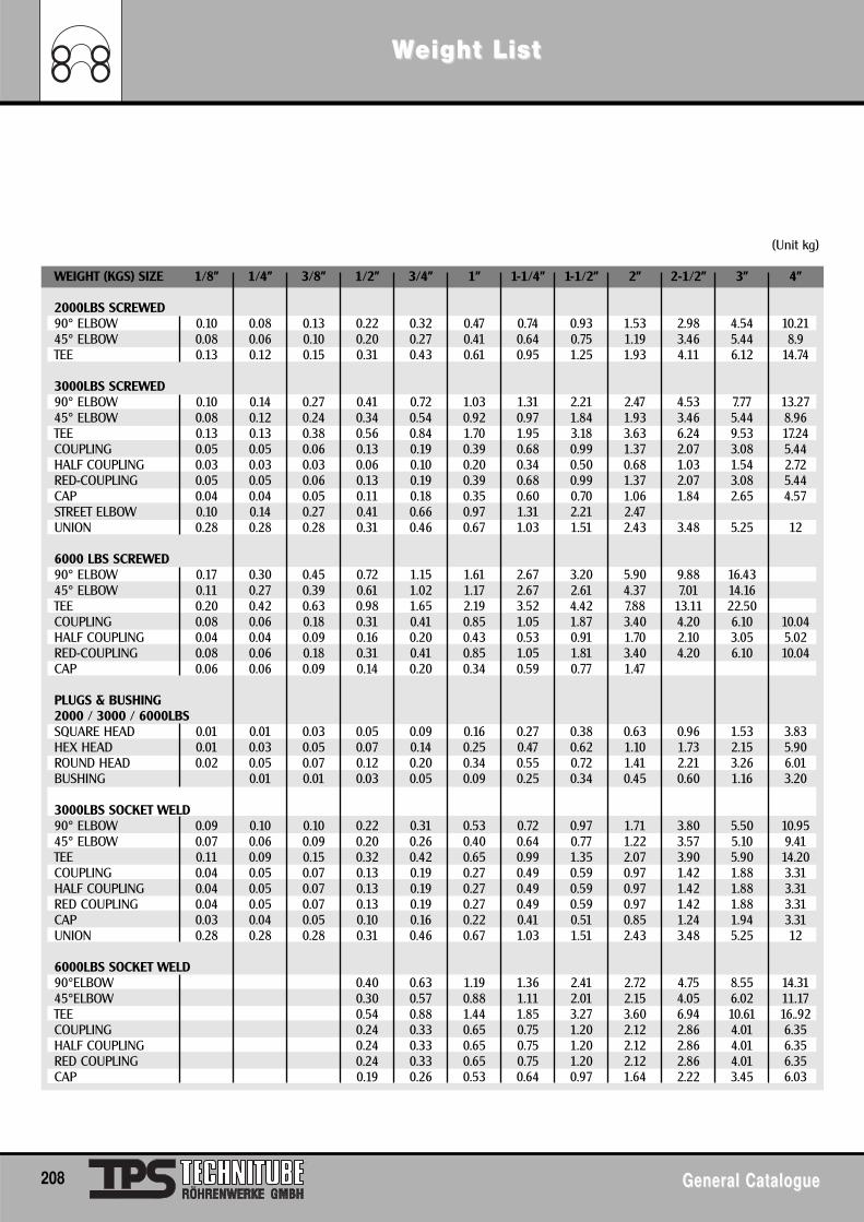
WWeight Liseight Listt
208 General CatalogueGeneral Catalogue
(Unit kg)
WEIGHT (KGS) SIZE 1/8" 1/4" 3/8" 1/2" 3/4" 1" 1-1/4" 1-1/2" 2" 2-1/2" 3" 4"
2000LBS SCREWED90° ELBOW 0.10 0.08 0.13 0.22 0.32 0.47 0.74 0.93 1.53 2.98 4.54 10.2145° ELBOW 0.08 0.06 0.10 0.20 0.27 0.41 0.64 0.75 1.19 3.46 5.44 8.9TEE 0.13 0.12 0.15 0.31 0.43 0.61 0.95 1.25 1.93 4.11 6.12 14.74
3000LBS SCREWED90° ELBOW 0.10 0.14 0.27 0.41 0.72 1.03 1.31 2.21 2.47 4.53 7.77 13.2745° ELBOW 0.08 0.12 0.24 0.34 0.54 0.92 0.97 1.84 1.93 3.46 5.44 8.96TEE 0.13 0.13 0.38 0.56 0.84 1.70 1.95 3.18 3.63 6.24 9.53 17.24COUPLING 0.05 0.05 0.06 0.13 0.19 0.39 0.68 0.99 1.37 2.07 3.08 5.44HALF COUPLING 0.03 0.03 0.03 0.06 0.10 0.20 0.34 0.50 0.68 1.03 1.54 2.72RED-COUPLING 0.05 0.05 0.06 0.13 0.19 0.39 0.68 0.99 1.37 2.07 3.08 5.44CAP 0.04 0.04 0.05 0.11 0.18 0.35 0.60 0.70 1.06 1.84 2.65 4.57STREET ELBOW 0.10 0.14 0.27 0.41 0.66 0.97 1.31 2.21 2.47UNION 0.28 0.28 0.28 0.31 0.46 0.67 1.03 1.51 2.43 3.48 5.25 12
6000 LBS SCREWED 90° ELBOW 0.17 0.30 0.45 0.72 1.15 1.61 2.67 3.20 5.90 9.88 16.4345° ELBOW 0.11 0.27 0.39 0.61 1.02 1.17 2.67 2.61 4.37 7.01 14.16TEE 0.20 0.42 0.63 0.98 1.65 2.19 3.52 4.42 7.88 13.11 22.50COUPLING 0.08 0.06 0.18 0.31 0.41 0.85 1.05 1.87 3.40 4.20 6.10 10.04HALF COUPLING 0.04 0.04 0.09 0.16 0.20 0.43 0.53 0.91 1.70 2.10 3.05 5.02RED-COUPLING 0.08 0.06 0.18 0.31 0.41 0.85 1.05 1.81 3.40 4.20 6.10 10.04CAP 0.06 0.06 0.09 0.14 0.20 0.34 0.59 0.77 1.47
PLUGS & BUSHING2000 / 3000 / 6000LBSSQUARE HEAD 0.01 0.01 0.03 0.05 0.09 0.16 0.27 0.38 0.63 0.96 1.53 3.83HEX HEAD 0.01 0.03 0.05 0.07 0.14 0.25 0.47 0.62 1.10 1.73 2.15 5.90ROUND HEAD 0.02 0.05 0.07 0.12 0.20 0.34 0.55 0.72 1.41 2.21 3.26 6.01BUSHING 0.01 0.01 0.03 0.05 0.09 0.25 0.34 0.45 0.60 1.16 3.20
3000LBS SOCKET WELD90° ELBOW 0.09 0.10 0.10 0.22 0.31 0.53 0.72 0.97 1.71 3.80 5.50 10.9545° ELBOW 0.07 0.06 0.09 0.20 0.26 0.40 0.64 0.77 1.22 3.57 5.10 9.41TEE 0.11 0.09 0.15 0.32 0.42 0.65 0.99 1.35 2.07 3.90 5.90 14.20COUPLING 0.04 0.05 0.07 0.13 0.19 0.27 0.49 0.59 0.97 1.42 1.88 3.31HALF COUPLING 0.04 0.05 0.07 0.13 0.19 0.27 0.49 0.59 0.97 1.42 1.88 3.31RED COUPLING 0.04 0.05 0.07 0.13 0.19 0.27 0.49 0.59 0.97 1.42 1.88 3.31CAP 0.03 0.04 0.05 0.10 0.16 0.22 0.41 0.51 0.85 1.24 1.94 3.31UNION 0.28 0.28 0.28 0.31 0.46 0.67 1.03 1.51 2.43 3.48 5.25 12
6000LBS SOCKET WELD90°ELBOW 0.40 0.63 1.19 1.36 2.41 2.72 4.75 8.55 14.3145°ELBOW 0.30 0.57 0.88 1.11 2.01 2.15 4.05 6.02 11.17TEE 0.54 0.88 1.44 1.85 3.27 3.60 6.94 10.61 16..92COUPLING 0.24 0.33 0.65 0.75 1.20 2.12 2.86 4.01 6.35HALF COUPLING 0.24 0.33 0.65 0.75 1.20 2.12 2.86 4.01 6.35RED COUPLING 0.24 0.33 0.65 0.75 1.20 2.12 2.86 4.01 6.35CAP 0.19 0.26 0.53 0.64 0.97 1.64 2.22 3.45 6.03
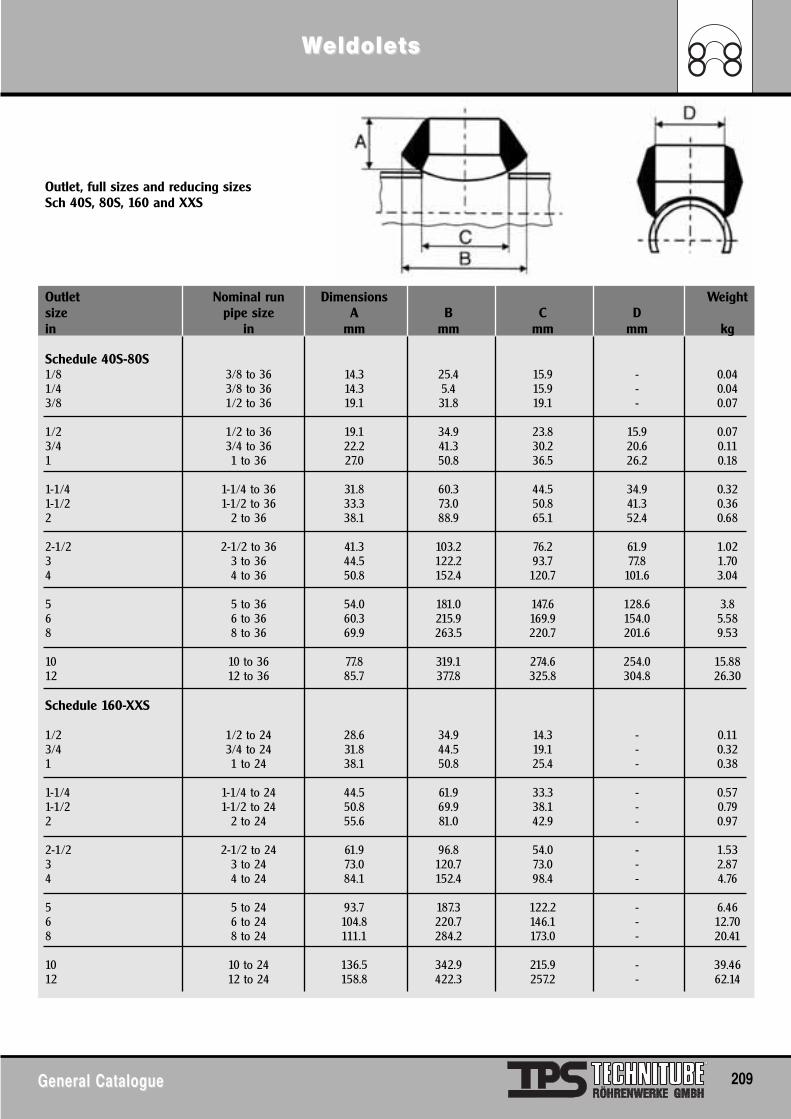
WWeldoleeldoletsts
General CatalogueGeneral Catalogue 209
Outlet, full sizes and reducing sizesSch 40S, 80S, 160 and XXS
Outlet Nominal run Dimensions Weightsize pipe size A B C Din in mm mm mm mm kg
Schedule 40S-80S1/8 3/8 to 36 14.3 25.4 15.9 - 0.041/4 3/8 to 36 14.3 5.4 15.9 - 0.043/8 1/2 to 36 19.1 31.8 19.1 - 0.07
1/2 1/2 to 36 19.1 34.9 23.8 15.9 0.073/4 3/4 to 36 22.2 41.3 30.2 20.6 0.111 1 to 36 27.0 50.8 36.5 26.2 0.18
1-1/4 1-1/4 to 36 31.8 60.3 44.5 34.9 0.321-1/2 1-1/2 to 36 33.3 73.0 50.8 41.3 0.362 2 to 36 38.1 88.9 65.1 52.4 0.68
2-1/2 2-1/2 to 36 41.3 103.2 76.2 61.9 1.023 3 to 36 44.5 122.2 93.7 77.8 1.704 4 to 36 50.8 152.4 120.7 101.6 3.04
5 5 to 36 54.0 181.0 147.6 128.6 3.86 6 to 36 60.3 215.9 169.9 154.0 5.588 8 to 36 69.9 263.5 220.7 201.6 9.53
10 10 to 36 77.8 319.1 274.6 254.0 15.8812 12 to 36 85.7 377.8 325.8 304.8 26.30
Schedule 160-XXS
1/2 1/2 to 24 28.6 34.9 14.3 - 0.113/4 3/4 to 24 31.8 44.5 19.1 - 0.321 1 to 24 38.1 50.8 25.4 - 0.38
1-1/4 1-1/4 to 24 44.5 61.9 33.3 - 0.571-1/2 1-1/2 to 24 50.8 69.9 38.1 - 0.792 2 to 24 55.6 81.0 42.9 - 0.97
2-1/2 2-1/2 to 24 61.9 96.8 54.0 - 1.533 3 to 24 73.0 120.7 73.0 - 2.874 4 to 24 84.1 152.4 98.4 - 4.76
5 5 to 24 93.7 187.3 122.2 - 6.466 6 to 24 104.8 220.7 146.1 - 12.708 8 to 24 111.1 284.2 173.0 - 20.41
10 10 to 24 136.5 342.9 215.9 - 39.4612 12 to 24 158.8 422.3 257.2 - 62.14
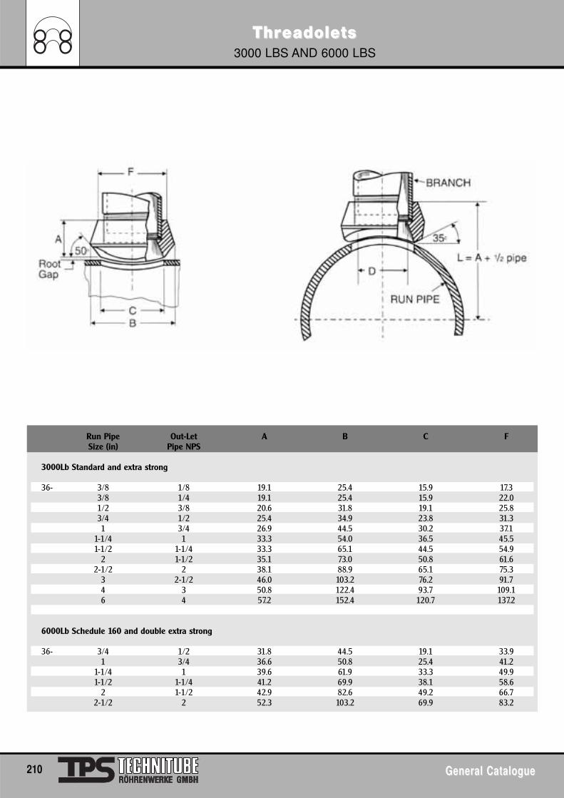
ThrThreadoleeadoletsts3000 LBS AND 6000 LBS
210 General CatalogueGeneral Catalogue
Run Pipe Out-Let A B C FSize (in) Pipe NPS
3000Lb Standard and extra strong
36- 3/8 1/8 19.1 25.4 15.9 17.33/8 1/4 19.1 25.4 15.9 22.01/2 3/8 20.6 31.8 19.1 25.83/4 1/2 25.4 34.9 23.8 31.31 3/4 26.9 44.5 30.2 37.1
1-1/4 1 33.3 54.0 36.5 45.51-1/2 1-1/4 33.3 65.1 44.5 54.9
2 1-1/2 35.1 73.0 50.8 61.62-1/2 2 38.1 88.9 65.1 75.3
3 2-1/2 46.0 103.2 76.2 91.74 3 50.8 122.4 93.7 109.16 4 57.2 152.4 120.7 137.2
6000Lb Schedule 160 and double extra strong
36- 3/4 1/2 31.8 44.5 19.1 33.91 3/4 36.6 50.8 25.4 41.2
1-1/4 1 39.6 61.9 33.3 49.91-1/2 1-1/4 41.2 69.9 38.1 58.6
2 1-1/2 42.9 82.6 49.2 66.72-1/2 2 52.3 103.2 69.9 83.2
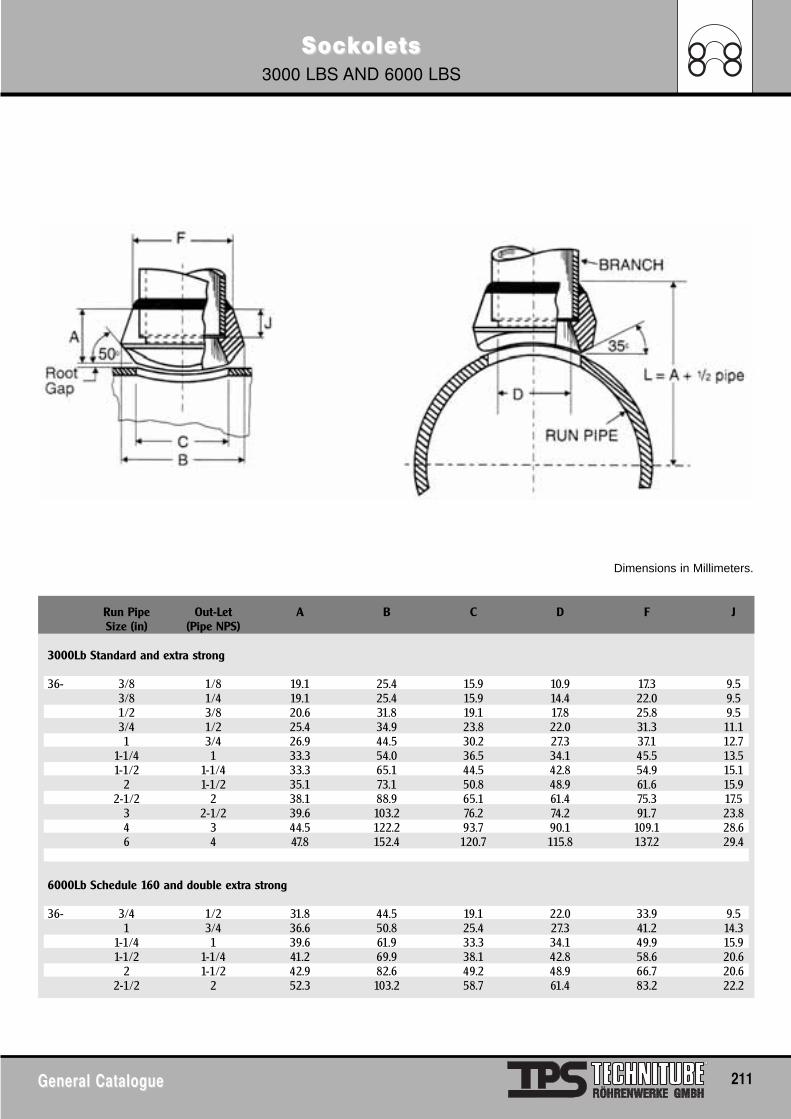
SocSockkoleoletsts3000 LBS AND 6000 LBS
General CatalogueGeneral Catalogue 211
Dimensions in Millimeters.
Run Pipe Out-Let A B C D F JSize (in) (Pipe NPS)
3000Lb Standard and extra strong
36- 3/8 1/8 19.1 25.4 15.9 10.9 17.3 9.53/8 1/4 19.1 25.4 15.9 14.4 22.0 9.51/2 3/8 20.6 31.8 19.1 17.8 25.8 9.53/4 1/2 25.4 34.9 23.8 22.0 31.3 11.11 3/4 26.9 44.5 30.2 27.3 37.1 12.7
1-1/4 1 33.3 54.0 36.5 34.1 45.5 13.51-1/2 1-1/4 33.3 65.1 44.5 42.8 54.9 15.1
2 1-1/2 35.1 73.1 50.8 48.9 61.6 15.92-1/2 2 38.1 88.9 65.1 61.4 75.3 17.5
3 2-1/2 39.6 103.2 76.2 74.2 91.7 23.84 3 44.5 122.2 93.7 90.1 109.1 28.66 4 47.8 152.4 120.7 115.8 137.2 29.4
6000Lb Schedule 160 and double extra strong
36- 3/4 1/2 31.8 44.5 19.1 22.0 33.9 9.51 3/4 36.6 50.8 25.4 27.3 41.2 14.3
1-1/4 1 39.6 61.9 33.3 34.1 49.9 15.91-1/2 1-1/4 41.2 69.9 38.1 42.8 58.6 20.6
2 1-1/2 42.9 82.6 49.2 48.9 66.7 20.62-1/2 2 52.3 103.2 58.7 61.4 83.2 22.2
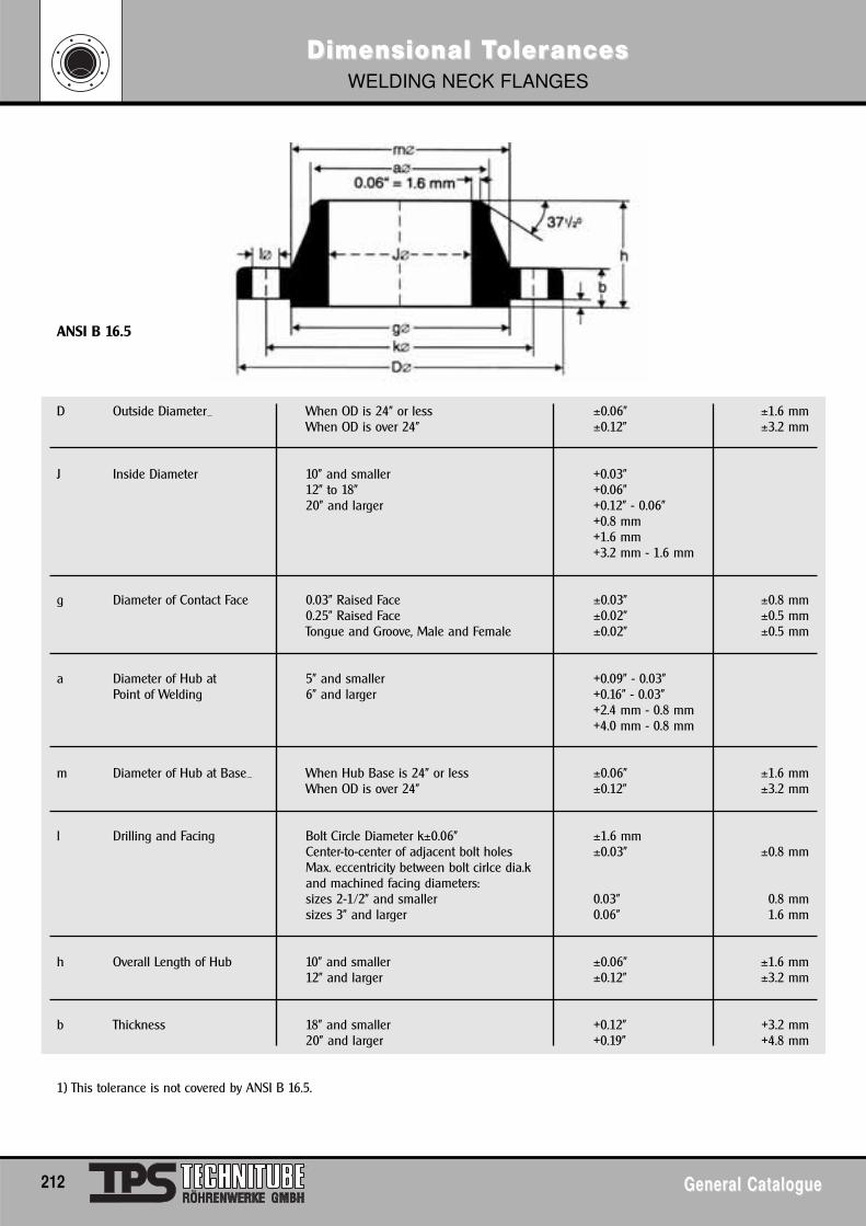
Dimensional TDimensional TolerolerancesancesWELDING NECK FLANGES
212 General CatalogueGeneral Catalogue
ANSI B 16.5
D Outside Diameter_ When OD is 24" or less ±0.06" ±1.6 mmWhen OD is over 24" ±0.12" ±3.2 mm
J Inside Diameter 10" and smaller +0.03"12" to 18" +0.06"20" and larger +0.12" - 0.06"
+0.8 mm+1.6 mm+3.2 mm - 1.6 mm
g Diameter of Contact Face 0.03" Raised Face ±0.03" ±0.8 mm0.25" Raised Face ±0.02" ±0.5 mmTongue and Groove, Male and Female ±0.02" ±0.5 mm
a Diameter of Hub at 5" and smaller +0.09" - 0.03"Point of Welding 6" and larger +0.16" - 0.03"
+2.4 mm - 0.8 mm+4.0 mm - 0.8 mm
m Diameter of Hub at Base_ When Hub Base is 24" or less ±0.06" ±1.6 mmWhen OD is over 24" ±0.12" ±3.2 mm
l Drilling and Facing Bolt Circle Diameter k±0.06" ±1.6 mmCenter-to-center of adjacent bolt holes ±0.03" ±0.8 mmMax. eccentricity between bolt cirlce dia.kand machined facing diameters:sizes 2-1/2" and smaller 0.03" 0.8 mmsizes 3" and larger 0.06" 1.6 mm
h Overall Length of Hub 10" and smaller ±0.06" ±1.6 mm12" and larger ±0.12" ±3.2 mm
b Thickness 18" and smaller +0.12" +3.2 mm20" and larger +0.19" +4.8 mm
1) This tolerance is not covered by ANSI B 16.5.
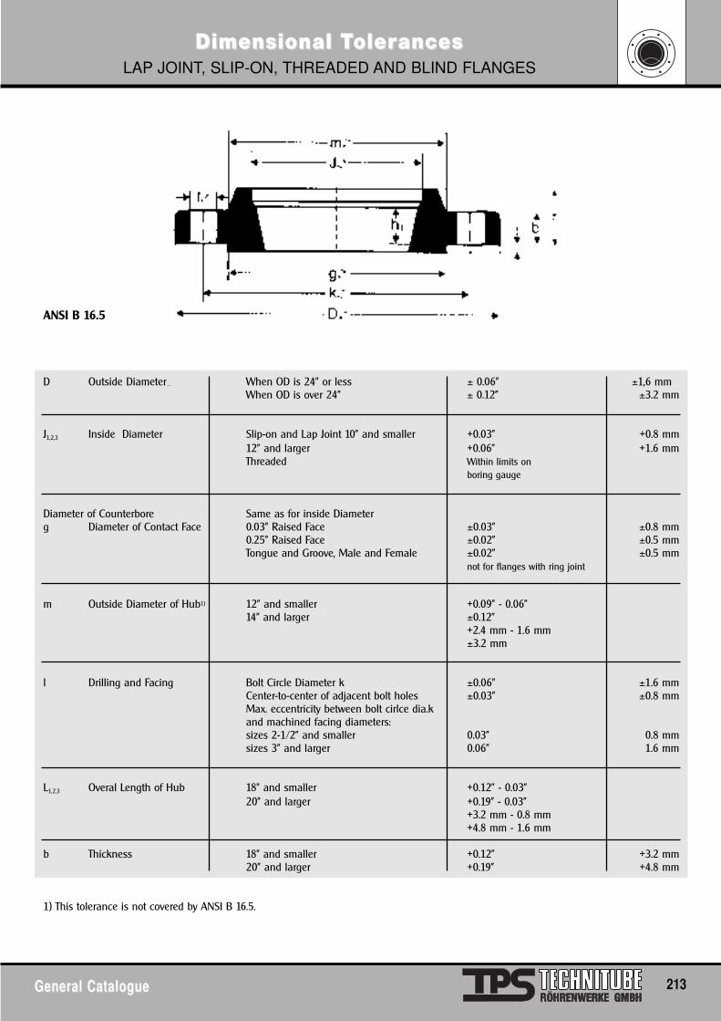
Dimensional TDimensional TolerolerancesancesLAP JOINT, SLIP-ON, THREADED AND BLIND FLANGES
General CatalogueGeneral Catalogue 213
ANSI B 16.5
D Outside Diameter_ When OD is 24" or less ± 0.06" ±1,6 mmWhen OD is over 24" ± 0.12" ±3.2 mm
J1,2,3 Inside Diameter Slip-on and Lap Joint 10" and smaller +0.03" +0.8 mm12" and larger +0.06" +1.6 mmThreaded Within limits on
boring gauge
Diameter of Counterbore Same as for inside Diameterg Diameter of Contact Face 0.03" Raised Face ±0.03" ±0.8 mm
0.25" Raised Face ±0.02" ±0.5 mmTongue and Groove, Male and Female ±0.02" ±0.5 mm
not for flanges with ring joint
m Outside Diameter of Hub1) 12" and smaller +0.09" - 0.06"14" and larger ±0.12"
+2.4 mm - 1.6 mm±3.2 mm
l Drilling and Facing Bolt Circle Diameter k ±0.06" ±1.6 mmCenter-to-center of adjacent bolt holes ±0.03" ±0.8 mmMax. eccentricity between bolt cirlce dia.kand machined facing diameters:sizes 2-1/2" and smaller 0.03" 0.8 mmsizes 3" and larger 0.06" 1.6 mm
L1,2,3 Overal Length of Hub 18" and smaller +0.12" - 0.03"20" and larger +0.19" - 0.03"
+3.2 mm - 0.8 mm+4.8 mm - 1.6 mm
b Thickness 18" and smaller +0.12" +3.2 mm20" and larger +0.19" +4.8 mm
1) This tolerance is not covered by ANSI B 16.5.
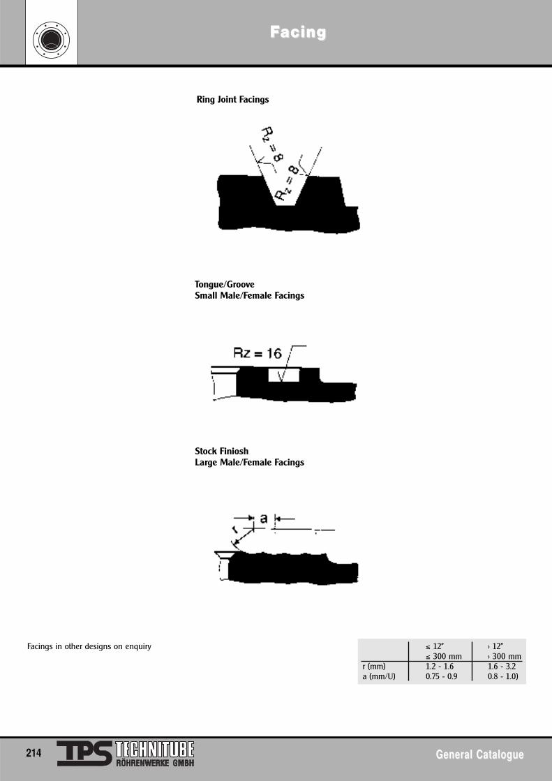
FFacingacing
214 General CatalogueGeneral Catalogue
Facings in other designs on enquiry ≤ 12" > 12"≤ 300 mm > 300 mm
r (mm) 1.2 - 1.6 1.6 - 3.2a (mm/U) 0.75 - 0.9 0.8 - 1.0)
Ring Joint Facings
Tongue/GrooveSmall Male/Female Facings
Stock FinioshLarge Male/Female Facings
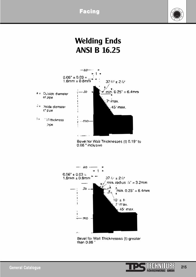
FFacingacing
General CatalogueGeneral Catalogue 215
Welding EndsANSI B 16.25
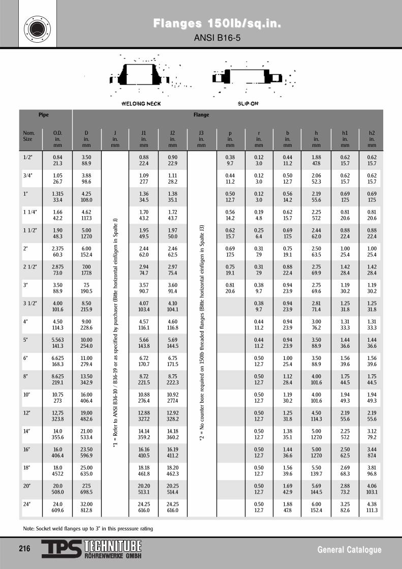
FlangFlanges 1es 150lb/sq.in.50lb/sq.in.ANSI B16-5
216 General CatalogueGeneral Catalogue
Pipe Flange
Nom. O.D. D J J1 J2 J3 p r b h h1 h2Size in. in. in. in. in. in. in. in. in. in. in. in.
mm mm mm mm mm mm mm mm mm mm mm mm
1/2" 0.84 3.50 0.88 0.90 0.38 0.12 0.44 1.88 0.62 0.6221.3 88.9 22.4 22.9 9.7 3.0 11.2 47.8 15.7 15.7
3/4" 1.05 3.88 1.09 1.11 0.44 0.12 0.50 2.06 0.62 0.6226.7 98.6 27.7 28.2 11.2 3.0 12.7 52.3 15.7 15.7
1" 1.315 4.25 1.36 1.38 0.50 0.12 0.56 2.19 0.69 0.6933.4 108.0 34.5 35.1 12.7 3.0 14.2 55.6 17.5 17.5
1 1/4" 1.66 4.62 1.70 1.72 0.56 0.19 0.62 2.25 0.81 0.8142.2 117.3 43.2 43.7 14.2 4.8 15.7 57.2 20.6 20.6
1 1/2" 1.90 5.00 1.95 1.97 0.62 0.25 0.69 2.44 0.88 0.8848.3 127.0 49.5 50.0 15.7 6.4 17.5 62.0 22.4 22.4
2" 2.375 6.00 2.44 2.46 0.69 0.31 0.75 2.50 1.00 1.0060.3 152.4 62.0 62.5 17.5 7.9 19.1 63.5 25.4 25.4
2 1/2" 2.875 7.00 2.94 2.97 0.75 0.31 0.88 2.75 1.42 1.4273.0 177.8 74.7 75.4 19.1 7.9 22.4 69.9 28.4 28.4
3" 3.50 7.5 3.57 3.60 0.81 0.38 0.94 2.75 1.19 1.1988.9 190.5 90.7 91.4 20.6 9.7 23.9 69.6 30.2 30.2
3 1/2" 4.00 8.50 4.07 4.10 0.38 0.94 2.81 1.25 1.25101.6 215.9 103.4 104.1 9.7 23.9 71.4 31.8 31.8
4" 4.50 9.00 4.57 4.60 0.44 0.94 3.00 1.31 1.31114.3 228.6 116.1 116.8 11.2 23.9 76.2 33.3 33.3
5" 5.563 10.00 5.66 5.69 0.44 0.94 3.50 1.44 1.44141.3 254.0 143.8 144.5 11.2 23.9 88.9 36.6 36.6
6" 6.625 11.00 6.72 6.75 0.50 1.00 3.50 1.56 1.56168.3 279.4 170.7 171.5 12.7 25.4 88.9 39.6 39.6
8" 8.625 13.50 8.72 8.75 0.50 1.12 4.00 1.75 1.75219.1 342.9 221.5 222.3 12.7 28.4 101.6 44.5 44.5
10" 10.75 16.00 10.88 10.92 0.50 1.19 4.00 1.94 1.94273 406.4 276.4 277.4 12.7 30.2 101.6 49.3 49.3
12" 12,75 19,00 12.88 12.92 0.50 1.25 4.50 2.19 2.19323.8 482.6 327.2 328.2 12.7 31.8 114.3 55.6 55.6
14" 14.0 21.00 14.14 14.18 0.50 1.38 5.00 2.25 3.12355.6 533.4 359.2 360.2 12.7 35.1 127.0 57.2 79.2
16" 16.0 23.50 16.16 16.19 0.50 1.44 5.00 2.50 3.44406.4 596.9 410.5 411.2 12.7 36.6 127.0 62.5 87.4
18" 18.0 25.00 18.18 18.20 0.50 1.56 5.50 2.69 3.81457.2 635.0 461.8 462.3 12.7 39.6 139.7 68.3 96.8
20" 20.0 27.5 20.20 20.25 0.50 1.69 5.69 2.88 4.06508.0 698.5 513.1 514.4 12.7 42.9 144.5 73.2 103.1
24" 24.0 32.00 24.25 24.25 0.50 1.88 6.00 3.25 4.38609.6 812.8 616.0 616.0 12.7 47.8 152.4 82.6 111.3
Note: Socket weld flanges up to 3" in this presssure rating
*1 =
Ref
er to
AN
SI B
36-1
0 /
B36-
19 o
r as
spe
cifie
d by
pur
chas
er (B
itte
horiz
onta
l ein
füge
n in
Spa
lte J
)
*2 =
No
coun
ter
bore
req
uire
d on
150
lb th
read
ed fl
ange
s (B
itte
horiz
onta
l ein
füge
n in
Spa
lte J
3)
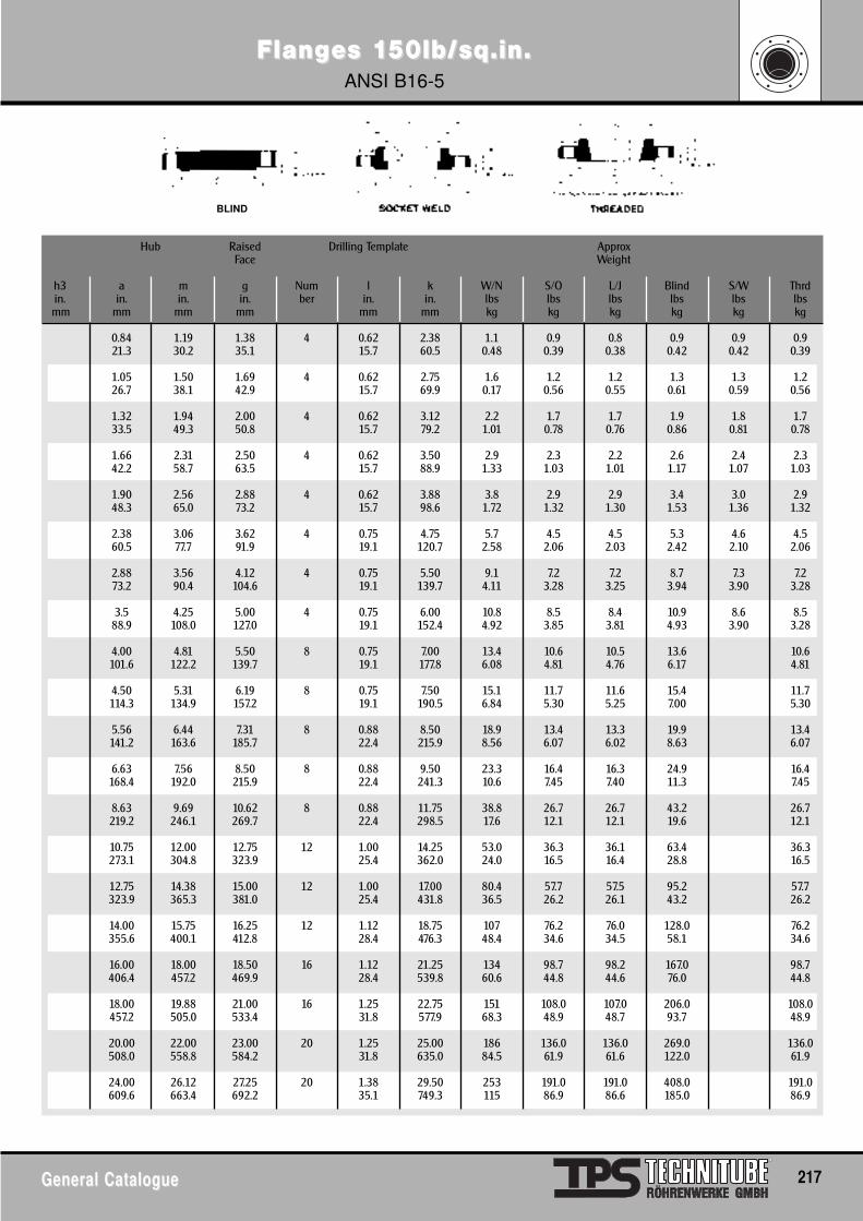
FlangFlanges 1es 150lb/sq.in.50lb/sq.in.ANSI B16-5
General CatalogueGeneral Catalogue 217
Hub Raised Drilling Template ApproxFace Weight
h3 a m g Num l k W/N S/O L/J Blind S/W Thrdin. in. in. in. ber in. in. lbs lbs lbs lbs lbs lbsmm mm mm mm mm mm kg kg kg kg kg kg
0.84 1.19 1.38 4 0.62 2.38 1.1 0.9 0.8 0.9 0.9 0.921.3 30.2 35.1 15.7 60.5 0.48 0.39 0.38 0.42 0.42 0.39
1.05 1.50 1.69 4 0.62 2.75 1.6 1.2 1.2 1.3 1.3 1.226.7 38.1 42.9 15.7 69.9 0.17 0.56 0.55 0.61 0.59 0.56
1.32 1.94 2.00 4 0.62 3.12 2.2 1.7 1.7 1.9 1.8 1.733.5 49.3 50.8 15.7 79.2 1.01 0.78 0.76 0.86 0.81 0.78
1.66 2.31 2.50 4 0.62 3.50 2.9 2.3 2.2 2.6 2.4 2.342.2 58.7 63.5 15.7 88.9 1.33 1.03 1.01 1.17 1.07 1.03
1.90 2.56 2.88 4 0.62 3.88 3.8 2.9 2.9 3.4 3.0 2.948.3 65.0 73.2 15.7 98.6 1.72 1.32 1.30 1.53 1.36 1.32
2.38 3.06 3.62 4 0.75 4.75 5.7 4.5 4.5 5.3 4.6 4.560.5 77.7 91.9 19.1 120.7 2.58 2.06 2.03 2.42 2.10 2.06
2.88 3.56 4.12 4 0.75 5.50 9.1 7.2 7.2 8.7 7.3 7.273.2 90.4 104.6 19.1 139.7 4.11 3.28 3.25 3.94 3.90 3.28
3.5 4.25 5.00 4 0.75 6.00 10.8 8.5 8.4 10.9 8.6 8.588.9 108.0 127.0 19.1 152.4 4.92 3.85 3.81 4.93 3.90 3.28
4.00 4.81 5.50 8 0.75 7.00 13.4 10.6 10.5 13.6 10.6101.6 122.2 139.7 19.1 177.8 6.08 4.81 4.76 6.17 4.81
4.50 5.31 6.19 8 0.75 7.50 15.1 11.7 11.6 15.4 11.7114.3 134.9 157.2 19.1 190.5 6.84 5.30 5.25 7.00 5.30
5.56 6.44 7.31 8 0.88 8.50 18.9 13.4 13.3 19.9 13.4141.2 163.6 185.7 22.4 215.9 8.56 6.07 6.02 8.63 6.07
6.63 7.56 8.50 8 0.88 9.50 23.3 16.4 16.3 24.9 16.4168.4 192.0 215.9 22.4 241.3 10.6 7.45 7.40 11.3 7.45
8.63 9.69 10.62 8 0.88 11.75 38.8 26.7 26.7 43.2 26.7219.2 246.1 269.7 22.4 298.5 17.6 12.1 12.1 19.6 12.1
10.75 12.00 12.75 12 1.00 14.25 53.0 36.3 36.1 63.4 36.3273.1 304.8 323.9 25.4 362.0 24.0 16.5 16.4 28.8 16.5
12.75 14.38 15.00 12 1.00 17.00 80.4 57.7 57.5 95.2 57.7323.9 365.3 381.0 25.4 431.8 36.5 26.2 26.1 43.2 26.2
14.00 15.75 16.25 12 1.12 18.75 107 76.2 76.0 128.0 76.2355.6 400.1 412.8 28.4 476.3 48.4 34.6 34.5 58.1 34.6
16.00 18.00 18.50 16 1.12 21.25 134 98.7 98.2 167.0 98.7406.4 457.2 469.9 28.4 539.8 60.6 44.8 44.6 76.0 44.8
18.00 19.88 21.00 16 1.25 22.75 151 108.0 107.0 206.0 108.0457.2 505.0 533.4 31.8 577.9 68.3 48.9 48.7 93.7 48.9
20.00 22.00 23.00 20 1.25 25.00 186 136.0 136.0 269.0 136.0508.0 558.8 584.2 31.8 635.0 84.5 61.9 61.6 122.0 61.9
24.00 26.12 27.25 20 1.38 29.50 253 191.0 191.0 408.0 191.0609.6 663.4 692.2 35.1 749.3 115 86.9 86.6 185.0 86.9
BLIND
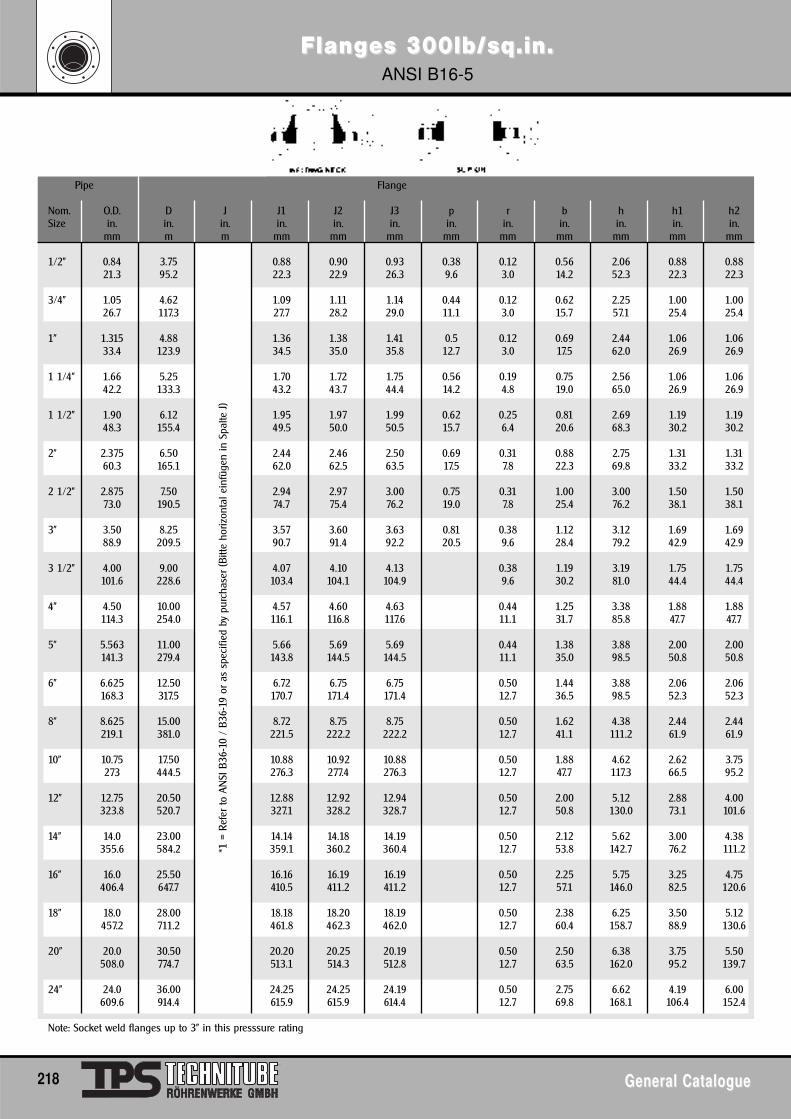
FlangFlanges 300lb/sq.in.es 300lb/sq.in.ANSI B16-5
218 General CatalogueGeneral Catalogue
*1 =
Ref
er to
AN
SI B
36-1
0 /
B36-
19 o
r as
spe
cifie
d by
pur
chas
er (B
itte
horiz
onta
l ein
füge
n in
Spa
lte J
)
Pipe Flange
Nom. O.D. D J J1 J2 J3 p r b h h1 h2Size in. in. in. in. in. in. in. in. in. in. in. in.
mm m m mm mm mm mm mm mm mm mm mm
1/2" 0.84 3.75 0.88 0.90 0.93 0.38 0.12 0.56 2.06 0.88 0.8821.3 95.2 22.3 22.9 26.3 9.6 3.0 14.2 52.3 22.3 22.3
3/4" 1.05 4.62 1.09 1.11 1.14 0.44 0.12 0.62 2.25 1.00 1.0026.7 117.3 27.7 28.2 29.0 11.1 3.0 15.7 57.1 25.4 25.4
1" 1.315 4.88 1.36 1.38 1.41 0.5 0.12 0.69 2.44 1.06 1.0633.4 123.9 34.5 35.0 35.8 12.7 3.0 17.5 62.0 26.9 26.9
1 1/4" 1.66 5.25 1.70 1.72 1.75 0.56 0.19 0.75 2.56 1.06 1.0642.2 133.3 43.2 43.7 44.4 14.2 4.8 19.0 65.0 26.9 26.9
1 1/2" 1.90 6.12 1.95 1.97 1.99 0.62 0.25 0.81 2.69 1.19 1.1948.3 155.4 49.5 50.0 50.5 15.7 6.4 20.6 68.3 30.2 30.2
2" 2.375 6.50 2.44 2.46 2.50 0.69 0.31 0.88 2.75 1.31 1.3160.3 165.1 62.0 62.5 63.5 17.5 7.8 22.3 69.8 33.2 33.2
2 1/2" 2.875 7.50 2.94 2.97 3.00 0.75 0.31 1.00 3.00 1.50 1.5073.0 190.5 74.7 75.4 76.2 19.0 7.8 25.4 76.2 38.1 38.1
3" 3.50 8.25 3.57 3.60 3.63 0.81 0.38 1.12 3.12 1.69 1.6988.9 209.5 90.7 91.4 92.2 20.5 9.6 28.4 79.2 42.9 42.9
3 1/2" 4.00 9.00 4.07 4.10 4.13 0.38 1.19 3.19 1.75 1.75101.6 228.6 103.4 104.1 104.9 9.6 30.2 81.0 44.4 44.4
4" 4.50 10.00 4.57 4.60 4.63 0.44 1.25 3.38 1.88 1.88114.3 254.0 116.1 116.8 117.6 11.1 31.7 85.8 47.7 47.7
5" 5.563 11.00 5.66 5.69 5.69 0.44 1.38 3.88 2.00 2.00141.3 279.4 143.8 144.5 144.5 11.1 35.0 98.5 50.8 50.8
6" 6.625 12.50 6.72 6.75 6.75 0.50 1.44 3.88 2.06 2.06168.3 317.5 170.7 171.4 171.4 12.7 36.5 98.5 52.3 52.3
8" 8.625 15.00 8.72 8.75 8.75 0.50 1.62 4.38 2.44 2.44219.1 381.0 221.5 222.2 222.2 12.7 41.1 111.2 61.9 61.9
10" 10.75 17.50 10.88 10.92 10.88 0.50 1.88 4.62 2.62 3.75273 444.5 276.3 277.4 276.3 12.7 47.7 117.3 66.5 95.2
12" 12.75 20.50 12.88 12.92 12.94 0.50 2.00 5.12 2.88 4.00323.8 520.7 327.1 328.2 328.7 12.7 50.8 130.0 73.1 101.6
14" 14.0 23.00 14.14 14.18 14.19 0.50 2.12 5.62 3.00 4.38355.6 584.2 359.1 360.2 360.4 12.7 53.8 142.7 76.2 111.2
16" 16.0 25.50 16.16 16.19 16.19 0.50 2.25 5.75 3.25 4.75406.4 647.7 410.5 411.2 411.2 12.7 57.1 146.0 82.5 120.6
18" 18.0 28.00 18.18 18.20 18.19 0.50 2.38 6.25 3.50 5.12457.2 711.2 461.8 462.3 462.0 12.7 60.4 158.7 88.9 130.6
20" 20.0 30.50 20.20 20.25 20.19 0.50 2.50 6.38 3.75 5.50508.0 774.7 513.1 514.3 512.8 12.7 63.5 162.0 95.2 139.7
24" 24.0 36.00 24.25 24.25 24.19 0.50 2.75 6.62 4.19 6.00609.6 914.4 615.9 615.9 614.4 12.7 69.8 168.1 106.4 152.4
Note: Socket weld flanges up to 3" in this presssure rating
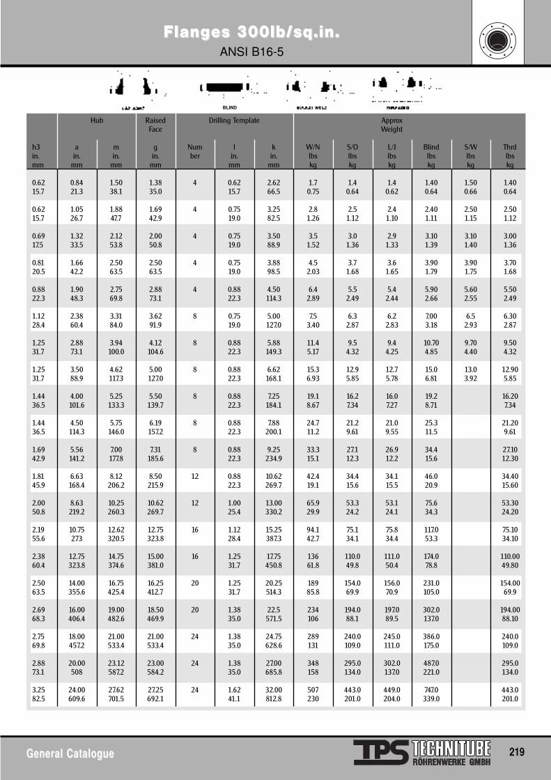
FlangFlanges 300lb/sq.in.es 300lb/sq.in.ANSI B16-5
General CatalogueGeneral Catalogue 219
Hub Raised Drilling Template ApproxFace Weight
h3 a m g Num l k W/N S/O L/J Blind S/W Thrdin. in. in. in. ber in. in. lbs lbs lbs lbs lbs lbsmm mm mm mm mm mm kg kg kg kg kg kg
0.62 0.84 1.50 1.38 4 0.62 2.62 1.7 1.4 1.4 1.40 1.50 1.4015.7 21.3 38.1 35.0 15.7 66.5 0.75 0.64 0.62 0.64 0.66 0.64
0.62 1.05 1.88 1.69 4 0.75 3.25 2.8 2.5 2.4 2.40 2.50 2.5015.7 26.7 47.7 42.9 19.0 82.5 1.26 1.12 1.10 1.11 1.15 1.12
0.69 1.32 2.12 2.00 4 0.75 3.50 3.5 3.0 2.9 3.10 3.10 3.0017.5 33.5 53.8 50.8 19.0 88.9 1.52 1.36 1.33 1.39 1.40 1.36
0.81 1.66 2.50 2.50 4 0.75 3.88 4.5 3.7 3.6 3.90 3.90 3.7020.5 42.2 63.5 63.5 19.0 98.5 2.03 1.68 1.65 1.79 1.75 1.68
0.88 1.90 2.75 2.88 4 0.88 4.50 6.4 5.5 5.4 5.90 5.60 5.5022.3 48.3 69.8 73.1 22.3 114.3 2.89 2.49 2.44 2.66 2.55 2.49
1.12 2.38 3.31 3.62 8 0.75 5.00 7.5 6.3 6.2 7.00 6.5 6.3028.4 60.4 84.0 91.9 19.0 127.0 3.40 2.87 2.83 3.18 2.93 2.87
1.25 2.88 3.94 4.12 8 0.88 5.88 11.4 9.5 9.4 10.70 9.70 9.5031.7 73.1 100.0 104.6 22.3 149.3 5.17 4.32 4.25 4.85 4.40 4.32
1.25 3.50 4.62 5.00 8 0.88 6.62 15.3 12.9 12.7 15.0 13.0 12.9031.7 88.9 117.3 127.0 22.3 168.1 6.93 5.85 5.78 6.81 3.92 5.85
1.44 4.00 5.25 5.50 8 0.88 7.25 19.1 16.2 16.0 19.2 16.2036.5 101.6 133.3 139.7 22.3 184.1 8.67 7.34 7.27 8.71 7.34
1.44 4.50 5.75 6.19 8 0.88 7.88 24.7 21.2 21.0 25.3 21.2036.5 114.3 146.0 157.2 22.3 200.1 11.2 9.61 9.55 11.5 9.61
1.69 5.56 7.00 7.31 8 0.88 9.25 33.3 27.1 26.9 34.4 27.1042.9 141.2 177.8 185.6 22.3 234.9 15.1 12.3 12.2 15.6 12.30
1.81 6.63 8.12 8.50 12 0.88 10.62 42.4 34.4 34.1 46.0 34.4045.9 168.4 206.2 215.9 22.3 269.7 19.1 15.6 15.5 20.9 15.60
2.00 8.63 10.25 10.62 12 1.00 13.00 65.9 53.3 53.1 75.6 53.3050.8 219.2 260.3 269.7 25.4 330.2 29.9 24.2 24.1 34.3 24.20
2.19 10.75 12.62 12.75 16 1.12 15.25 94.1 75.1 75.8 117.0 75.1055.6 273 320.5 323.8 28.4 387.3 42.7 34.1 34.4 53.3 34.10
2.38 12.75 14.75 15.00 16 1.25 17.75 136 110.0 111.0 174.0 110.0060.4 323.8 374.6 381.0 31.7 450.8 61.8 49.8 50.4 78.8 49.80
2.50 14.00 16.75 16.25 20 1.25 20.25 189 154.0 156.0 231.0 154.0063.5 355.6 425.4 412.7 31.7 514.3 85.8 69.9 70.9 105.0 69.9
2.69 16.00 19.00 18.50 20 1.38 22.5 234 194.0 197.0 302.0 194.0068.3 406.4 482.6 469.9 35.0 571.5 106 88.1 89.5 137.0 88.10
2.75 18.00 21.00 21.00 24 1.38 24.75 289 240.0 245.0 386.0 240.069.8 457.2 533.4 533.4 35.0 628.6 131 109.0 111.0 175.0 109.0
2.88 20.00 23.12 23.00 24 1.38 27.00 348 295.0 302.0 487.0 295.073.1 508 587.2 584.2 35.0 685.8 158 134.0 137.0 221.0 134.0
3.25 24.00 27.62 27.25 24 1.62 32.00 507 443.0 449.0 747.0 443.082.5 609.6 701.5 692.1 41.1 812.8 230 201.0 204.0 339.0 201.0
BLIND
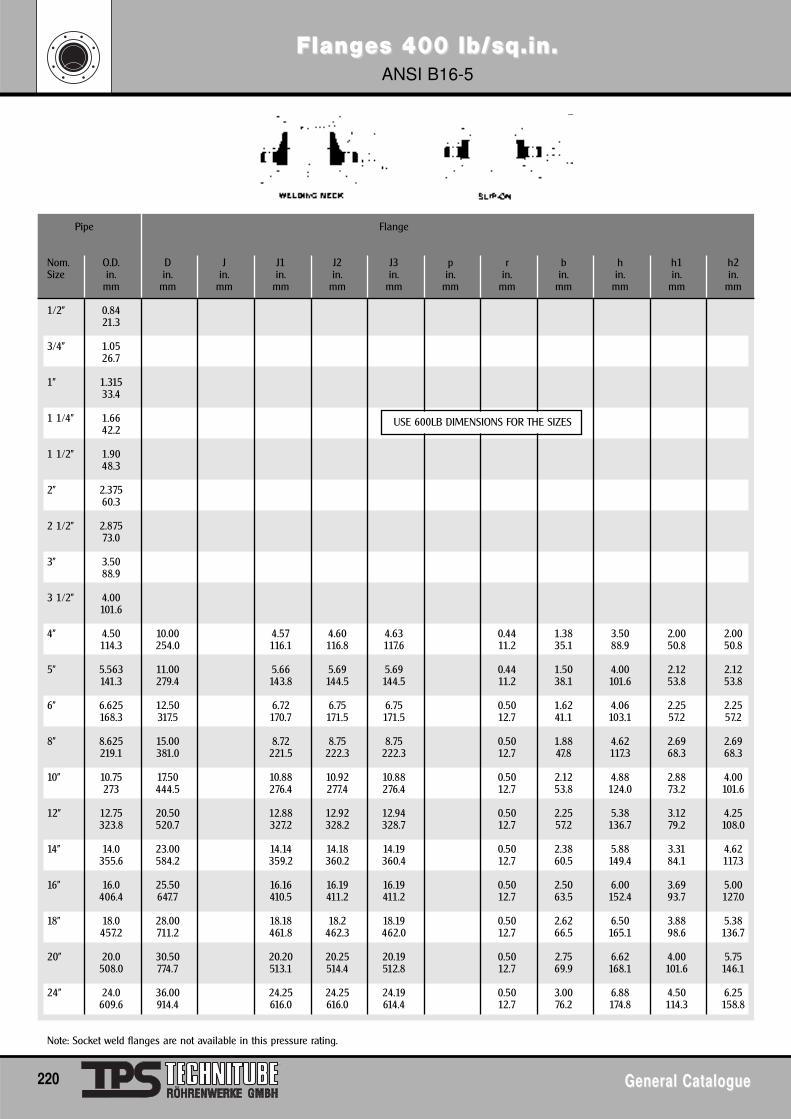
FlangFlanges 400 lb/sq.in.es 400 lb/sq.in.ANSI B16-5
220 General CatalogueGeneral Catalogue
Pipe Flange
Nom. O.D. D J J1 J2 J3 p r b h h1 h2Size in. in. in. in. in. in. in. in. in. in. in. in.
mm mm mm mm mm mm mm mm mm mm mm mm
1/2" 0.8421.3
3/4" 1.0526.7
1" 1.31533.4
1 1/4" 1.6642.2
1 1/2" 1.9048.3
2" 2.37560.3
2 1/2" 2.87573.0
3" 3.5088.9
3 1/2" 4.00101.6
4" 4.50 10.00 4.57 4.60 4.63 0.44 1.38 3.50 2.00 2.00114.3 254.0 116.1 116.8 117.6 11.2 35.1 88.9 50.8 50.8
5" 5.563 11.00 5.66 5.69 5.69 0.44 1.50 4.00 2.12 2.12141.3 279.4 143.8 144.5 144.5 11.2 38.1 101.6 53.8 53.8
6" 6.625 12.50 6.72 6.75 6.75 0.50 1.62 4.06 2.25 2.25168.3 317.5 170.7 171.5 171.5 12.7 41.1 103.1 57.2 57.2
8" 8.625 15.00 8.72 8.75 8.75 0.50 1.88 4.62 2.69 2.69219.1 381.0 221.5 222.3 222.3 12.7 47.8 117.3 68.3 68.3
10" 10.75 17.50 10.88 10.92 10.88 0.50 2.12 4.88 2.88 4.00273 444.5 276.4 277.4 276.4 12.7 53.8 124.0 73.2 101.6
12" 12.75 20.50 12.88 12.92 12.94 0.50 2.25 5.38 3.12 4.25323.8 520.7 327.2 328.2 328.7 12.7 57.2 136.7 79.2 108.0
14" 14.0 23.00 14.14 14.18 14.19 0.50 2.38 5.88 3.31 4.62355.6 584.2 359.2 360.2 360.4 12.7 60.5 149.4 84.1 117.3
16" 16.0 25.50 16.16 16.19 16.19 0.50 2.50 6.00 3.69 5.00406.4 647.7 410.5 411.2 411.2 12.7 63.5 152.4 93.7 127.0
18" 18.0 28.00 18.18 18.2 18.19 0.50 2.62 6.50 3.88 5.38457.2 711.2 461.8 462.3 462.0 12.7 66.5 165.1 98.6 136.7
20" 20.0 30.50 20.20 20.25 20.19 0.50 2.75 6.62 4.00 5.75508.0 774.7 513.1 514.4 512.8 12.7 69.9 168.1 101.6 146.1
24" 24.0 36.00 24.25 24.25 24.19 0.50 3.00 6.88 4.50 6.25609.6 914.4 616.0 616.0 614.4 12.7 76.2 174.8 114.3 158.8
Note: Socket weld flanges are not available in this pressure rating.
USE 600LB DIMENSIONS FOR THE SIZES

BLIND
FlangFlanges 400 lb/sq.in.es 400 lb/sq.in.ANSI B16-5
General CatalogueGeneral Catalogue 221
Hub Raised Drilling Template ApproxFace Weight
h a m g Num l k W/N S/O L/J Blind S/W Thrdin. in. in. in. ber in. in. lbs lbs lbs lbs lbs lbsmm mm mm mm mm mm kg kg kg kg kg kg
1.44 4.50 5.75 6.19 8 1.00 7.88 28.2 24.4 24.0 30.2 24.436.6 114.3 146.1 157.2 25.4 200.2 12.8 11.1 10.9 13.7 11.1
1.69 5.56 7.00 7.31 8 1.00 9.25 37.2 30.6 30.2 40.7 30.642.9 141.2 177.8 185.7 25.4 235.0 16.9 13.9 13.7 18.5 13.7
1.81 6.63 8.12 8.50 12 1.00 10.62 48.5 40.3 39.6 56.2 40.346.0 168.4 206.2 215.9 25.4 269.7 22.0 18.3 18.0 25.5 18.3
2.00 8.63 10.25 10.62 12 1.12 13.00 76.4 63.0 62.3 93.8 63.050.8 219.2 260.4 269.7 28.4 330.2 34.7 28.6 28.3 42.6 28.6
2.19 10.75 12.62 12.75 16 1.25 15.25 107 86.3 85.5 142 86.355.6 273.1 320.5 323.9 31.8 387.4 48.5 39.2 38.8 64.5 39.2
2.38 12.75 14.75 15.00 16 1.38 17.75 153 126 125 208 12660.5 323.9 374.7 381.0 35.1 450.9 69.6 57.0 56.6 94.3 57.0
2.50 14.00 16.75 16.25 20 1.38 20.25 210 174 173 273 17463.5 355.6 425.5 412.8 35.1 514.4 95.5 79.1 78.6 124 79.1
2.69 16.00 19.00 18.50 20 1.50 22.50 260 223 220 357 22368.3 406.4 482.6 469.9 38.1 571.5 118 101 100 162 101
2.75 18.00 21.00 21.00 24 1.50 24.75 319 271 269 452 27169.9 457.2 533.4 533.4 38.1 628.7 145 123 122 205 123
2.88 20.00 23.12 23.00 24 1.62 27.00 381 322 319 560 32273.2 508.0 587.2 584.2 41.1 685.8 173 146 145 254 146
3.25 24.00 27.62 27.25 24 1.88 32.00 549 482 478 850 48282.6 609.6 701.5 692.2 47.8 812.8 249 219 217 386 219
USE 600LB DIMENSIONS FOR THESE SIZES
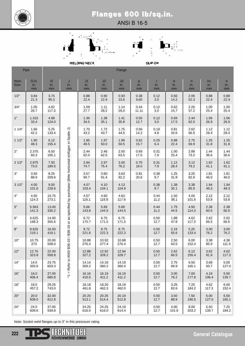
FlangFlanges 600 lb/sq.in.es 600 lb/sq.in.ANSI B 16-5
222 General CatalogueGeneral Catalogue
Pipe Flange
Nom. O.D. D J J1 J2 J3 p r b h h1 hSize in. in. in. in. in. in. in. in. in. in. in. in.
mm mm mm mm mm mm mm mm mm mm mm mm
1/2" 0.84 3.75 0.88 0.90 0.93 0.38 0.12 0.56 2.06 0.88 0.8821.3 95.3 22.4 22.9 23.6 9,60 3.0 14.2 52.3 22.4 22.4
3/4" 1.05 4.62 1.09 1.11 1.14 0.44 0.12 0.62 2.25 1.00 1.0026.7 117.3 27.7 28.2 29.0 11.11 3.0 15.7 57.2 25.4 25.4
1" 1.315 4.88 1.36 1.38 1.41 0.50 0.12 0.69 2.44 1.06 1.0633.4 124.0 34.5 35.1 35.8 12.7 3.0 17.5 62.0 26.9 26.9
1 1/4" 1.66 5.25 1.70 1.72 1.75 0.56 0.19 0.81 2.62 1.12 1.1242.2 133.4 43.2 43.7 44.5 14.2 4.8 20.6 66.5 28.4 28.4
1 1/2" 1.90 6.12 1.95 1.97 1.99 0.62 0.25 0.88 2.75 1.25 1.2548.3 155.4 49.5 50.0 50.5 15.7 6.4 22.4 69.9 31.8 31.8
2" 2.375 6.50 2.44 2.46 2.50 0.69 0.31 1.00 2.88 1.44 1.4460.3 165.1 62.0 62.5 63.5 17.5 7.9 25.4 73.2 36.6 36.6
2 1/2" 2.875 7.50 2.94 2.97 3.00 0.75 0.31 1.12 3.12 1.62 1.6273.0 190.5 74.7 75.4 76.2 19.0 7.9 28.4 79.2 41.1 41.1
3" 3.50 8.25 3.57 3.60 3.63 0.81 0.38 1.25 3.25 1.81 1.8188.9 209.6 90.7 91.4 92.2 20.6 9.7 31.8 82.6 46.0 46.0
3 1/2" 4.00 9.00 4.07 4.10 4.13 0.38 1.38 3.38 1.94 1.94101.6 228.6 103.4 104.1 104.9 9.7 35.1 85.9 49.3 49.3
4" 4.50 10.75 4.57 4.60 4.63 0.44 1.50 4.00 2.12 2.12114.3 273.1 116.1 116.8 117.6 11.2 38.1 101.6 53.8 53.8
5" 5.563 13.00 5.66 5.69 5.69 0.44 1.75 4.50 2.38 2.38141.3 330.2 143.8 144.5 144.5 11.2 44.5 114.3 60.5 60.5
6" 6.625 14.00 6.72 6.75 6.75 0.50 1.88 4.62 2.62 2.62168.3 355.6 170.7 171.5 171.5 12.7 47.8 117.3 66.5 66.5
8" 8.625 16.50 8.72 8.75 8.75 0.50 2.19 5.25 3.00 3.00219.1 419.1 221.8 222.3 222.3 12.7 55.6 133.4 76.2 76.2
10" 10.75 20.00 10.88 10.92 10.88 0.50 2.50 6.00 3.38 4.38273 508.0 276.4 277.4 276.4 12.7 63.5 152.4 85.9 111.3
12" 12.75 22.00 12.88 12.92 12.94 0.50 2.62 6.12 3.62 4.62323.8 558.8 327.2 328.2 328.7 12.7 66.5 155.4 91.9 117.3
14" 14.0 23.75 14.14 14.18 14.19 0.50 2.75 6.50 3.69 5.00355.6 603.3 359.2 360.2 360.4 12.7 69.9 165.1 93.7 127.0
16" 16.0 27.00 16.16 16.19 16.19 0.50 3.00 7.00 4.19 5.50406.4 685.8 410.5 411.2 411.2 12.7 76.2 177.8 106.4 139.7
18" 18.0 29.25 18.18 18.20 18.19 0.50 3.25 7.25 4.62 6.00457.2 743.0 461.8 462.3 462.0 12.7 82.6 184.2 117.3 152.4
20" 20.0 32.00 20.20 20.25 20.19 0.50 3.50 7.50 5.00 6.50508.0 812.8 513.1 514.4 512.8 12.7 88.9 190.5 127.0 165.1
24" 24.0 37.00 24.25 24.25 24.19 0.50 4.00 8.00 5.50 7.25609.6 939.8 616.0 616.0 614.4 12.7 101.6 203.2 139.7 184.2
Note: Socket weld flanges up to 3" in this presssure rating
*1 =
Ref
er t
o A
NS
I B
36-1
0 /
B36
-19
or a
s sp
ecifi
ed b
y pu
rcha
ser
(Bitt
e ho
rizon
tal e
infü
gen
in S
palte
J)
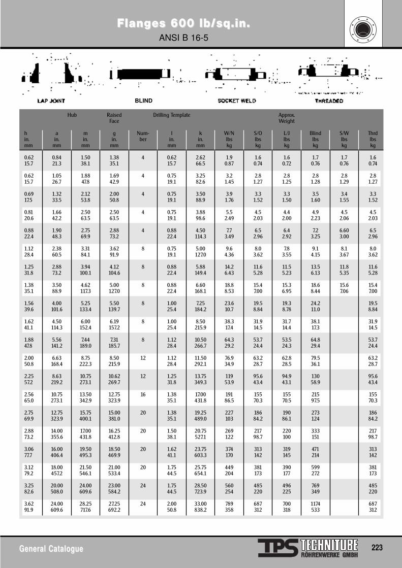
BLIND
FlangFlanges 600 lb/sq.in.es 600 lb/sq.in.ANSI B 16-5
General CatalogueGeneral Catalogue 223
Hub Raised Drilling Template Approx.Face Weight
h a m g Num- l k W/N S/O L/J Blind S/W Thrdin. in. in. in. ber in. in. lbs lbs lbs lbs lbs lbsmm mm mm mm mm mm kg kg kg kg kg kg
0.62 0.84 1.50 1.38 4 0.62 2.62 1.9 1.6 1.6 1.7 1.7 1.615.7 21.3 38.1 35.1 15.7 66.5 0.87 0.74 0.72 0.76 0.76 0.74
0.62 1.05 1.88 1.69 4 0.75 3.25 3.2 2.8 2.8 2.8 2.8 2.815.7 26.7 47.8 42.9 19.1 82.6 1.45 1.27 1.25 1.28 1.29 1.27
0.69 1.32 2.12 2.00 4 0.75 3.50 3.9 3.3 3.3 3.5 3.4 3.317.5 33.5 53.8 50.8 19.1 88.9 1.76 1.52 1.50 1.60 1.55 1.52
0.81 1.66 2.50 2.50 4 0.75 3.88 5.5 4.5 4.4 4.9 4.5 4.520.6 42.2 63.5 63.5 19.1 98.6 2.49 2.03 2.00 2.23 2.06 2.03
0.88 1.90 2.75 2.88 4 0.88 4.50 7.7 6.5 6.4 7.2 6.60 6.522.4 48.3 69.9 73.2 22.4 114.3 3.49 2.96 2.92 3.25 3.00 2.96
1.12 2.38 3.31 3.62 8 0.75 5.00 9.6 8.0 7.8 9.1 8.1 8.028.4 60.5 84.1 91.9 19.1 127.0 4.36 3.62 3.55 4.15 3.67 3.62
1.25 2.88 3.94 4.12 8 0.88 5.88 14.2 11.6 11.5 13.5 11.8 11.631.8 73.2 100.1 104.6 22.4 149.4 6.43 5.28 5.23 6.13 5.35 5.28
1.38 3.50 4.62 5.00 8 0.88 6.60 18.8 15.4 15.3 18.6 15.6 15.435.1 88.9 117.3 127.0 22.4 168.1 8.53 7.00 6.95 8.44 7.06 7.00
1.56 4.00 5.25 5.50 8 1.00 7.25 23.6 19.5 19.3 24.2 19.539.6 101.6 133.4 139.7 25.4 184.2 10.7 8.84 8.78 11.0 8.84
1.62 4.50 6.00 6.19 8 1.00 8.50 38.3 31.9 31.7 38.1 31.941.1 114.3 152.4 157.2 25.4 215.9 17.4 14.5 14.4 17.3 14.5
1.88 5.56 7.44 7.31 8 1.12 10.50 64.3 53.7 53.5 64.8 53.747.8 141.2 189.0 185.7 28.4 266.7 29.2 24.4 24.3 29.4 24.4
2.00 6.63 8.75 8.50 12 1.12 11.50 76.9 63.2 62.8 79.5 63.250.8 168.4 222.3 215.9 28.4 292.1 34.9 28.7 28.5 36.1 28.7
2.25 8.63 10.75 10.62 12 1.25 13.75 119 95.6 94.9 130 95.657.2 219.2 273.1 269.7 31.8 349.3 53.9 43.4 43.1 58.9 43.4
2.56 10.75 13.50 12.75 16 1.38 17.00 191 155 155 215 15565.0 273.1 342.9 323.9 35.1 431.8 86.5 70.3 70.5 97.5 70.3
2.75 12.75 15.75 15.00 20 1.38 19.25 227 186 190 273 18669.9 323.9 400.1 381.0 35.1 489.0 103 84.2 86.1 124 84.2
2.88 14.00 17.00 16.25 20 1.50 20.75 269 217 220 333 21773.2 355.6 431.8 412.8 38.1 527.1 122 98.7 100 151 98.7
3.06 16.00 19.50 18.50 20 1.62 23.75 374 313 319 471 31377.7 406.4 495.3 469.9 41.1 603.3 170 142 145 214 142
3.12 18.00 21.50 21.00 20 1.75 25.75 449 381 390 599 38179.2 457.2 546.1 533.4 44.5 654.1 204 173 177 272 173
3.25 20.00 24.00 23.00 24 1.75 28.50 560 485 496 769 48582.6 508.0 609.6 584.2 44.5 723.9 254 220 225 349 220
3.62 24.00 28.25 27.25 24 2.00 33.00 789 687 700 1174 68791.9 609.6 717.6 692.2 50.8 838.2 358 312 318 533 312
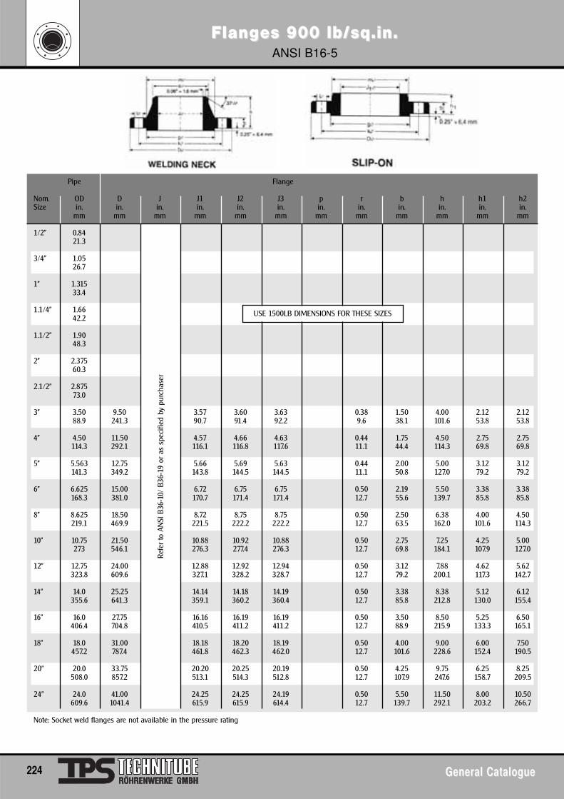
FlangFlanges 900 lb/sq.in.es 900 lb/sq.in.ANSI B16-5
224 General CatalogueGeneral Catalogue
Pipe Flange
Nom. OD D J J1 J2 J3 p r b h h1 h2Size in. in. in. in. in. in. in. in. in. in. in. in.
mm mm mm mm mm mm mm mm mm mm mm mm
1/2" 0.8421.3
3/4" 1.0526.7
1" 1.31533.4
1.1/4" 1.6642.2
1.1/2" 1.9048.3
2" 2.37560.3
2.1/2" 2.87573.0
3" 3.50 9.50 3.57 3.60 3.63 0.38 1.50 4.00 2.12 2.1288.9 241.3 90.7 91.4 92.2 9.6 38.1 101.6 53.8 53.8
4" 4.50 11.50 4.57 4.66 4.63 0.44 1.75 4.50 2.75 2.75114.3 292.1 116.1 116.8 117.6 11.1 44.4 114.3 69.8 69.8
5" 5.563 12.75 5.66 5.69 5.63 0.44 2.00 5.00 3.12 3.12141.3 349.2 143.8 144.5 144.5 11.1 50.8 127.0 79.2 79.2
6" 6.625 15.00 6.72 6.75 6.75 0.50 2.19 5.50 3.38 3.38168.3 381.0 170.7 171.4 171.4 12.7 55.6 139.7 85.8 85.8
8" 8.625 18.50 8.72 8.75 8.75 0.50 2.50 6.38 4.00 4.50219.1 469.9 221.5 222.2 222.2 12.7 63.5 162.0 101.6 114.3
10" 10.75 21.50 10.88 10.92 10.88 0.50 2.75 7.25 4.25 5.00273 546.1 276.3 277.4 276.3 12.7 69.8 184.1 107.9 127.0
12" 12.75 24.00 12.88 12.92 12.94 0.50 3.12 7.88 4.62 5.62323.8 609.6 327.1 328.2 328.7 12.7 79.2 200.1 117.3 142.7
14" 14.0 25.25 14.14 14.18 14.19 0.50 3.38 8.38 5.12 6.12355.6 641.3 359.1 360.2 360.4 12.7 85.8 212.8 130.0 155.4
16" 16.0 27.75 16.16 16.19 16.19 0.50 3.50 8.50 5.25 6.50406.4 704.8 410.5 411.2 411.2 12.7 88.9 215.9 133.3 165.1
18" 18.0 31.00 18.18 18.20 18.19 0.50 4.00 9.00 6.00 7.50457.2 787.4 461.8 462.3 462.0 12.7 101.6 228.6 152.4 190.5
20" 20.0 33.75 20.20 20.25 20.19 0.50 4.25 9.75 6.25 8.25508.0 857.2 513.1 514.3 512.8 12.7 107.9 247.6 158.7 209.5
24" 24.0 41.00 24.25 24.25 24.19 0.50 5.50 11.50 8.00 10.50609.6 1041.4 615.9 615.9 614.4 12.7 139.7 292.1 203.2 266.7
Note: Socket weld flanges are not available in the pressure rating
USE 1500LB DIMENSIONS FOR THESE SIZES
Refe
r to
AN
SI B
36-1
0/ B
36-1
9 or
as
spec
ified
by
purc
hase
r
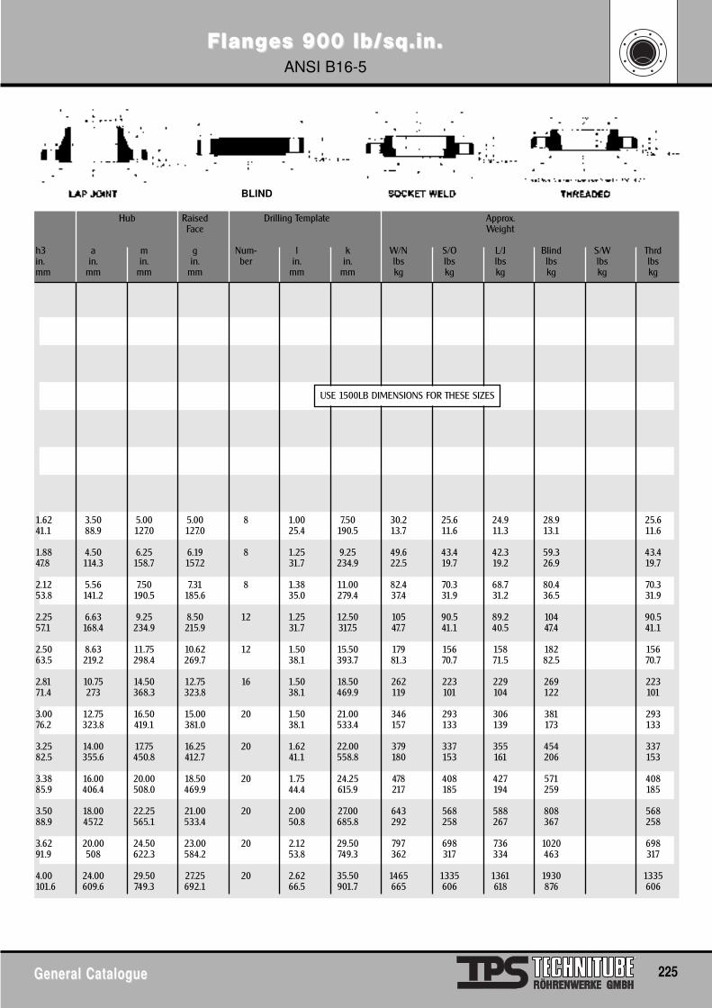
FlangFlanges 900 lb/sq.in.es 900 lb/sq.in.ANSI B16-5
General CatalogueGeneral Catalogue 225
Hub Raised Drilling Template Approx.Face Weight
h3 a m g Num- l k W/N S/O L/J Blind S/W Thrdin. in. in. in. ber in. in. lbs lbs lbs lbs lbs lbsmm mm mm mm mm mm kg kg kg kg kg kg
1.62 3.50 5.00 5.00 8 1.00 7.50 30.2 25.6 24.9 28.9 25.641.1 88.9 127.0 127.0 25.4 190.5 13.7 11.6 11.3 13.1 11.6
1.88 4.50 6.25 6.19 8 1.25 9.25 49.6 43.4 42.3 59.3 43.447.8 114.3 158.7 157.2 31.7 234.9 22.5 19.7 19.2 26.9 19.7
2.12 5.56 7.50 7.31 8 1.38 11.00 82.4 70.3 68.7 80.4 70.353.8 141.2 190.5 185.6 35.0 279.4 37.4 31.9 31.2 36.5 31.9
2.25 6.63 9.25 8.50 12 1.25 12.50 105 90.5 89.2 104 90.557.1 168.4 234.9 215.9 31.7 317.5 47.7 41.1 40.5 47.4 41.1
2.50 8.63 11.75 10.62 12 1.50 15.50 179 156 158 182 15663.5 219.2 298.4 269.7 38.1 393.7 81.3 70.7 71.5 82.5 70.7
2.81 10.75 14.50 12.75 16 1.50 18.50 262 223 229 269 22371.4 273 368.3 323.8 38.1 469.9 119 101 104 122 101
3.00 12.75 16.50 15.00 20 1.50 21.00 346 293 306 381 29376.2 323.8 419.1 381.0 38.1 533.4 157 133 139 173 133
3.25 14.00 17.75 16.25 20 1.62 22.00 379 337 355 454 33782.5 355.6 450.8 412.7 41.1 558.8 180 153 161 206 153
3.38 16.00 20.00 18.50 20 1.75 24.25 478 408 427 571 40885.9 406.4 508.0 469.9 44.4 615.9 217 185 194 259 185
3.50 18.00 22.25 21.00 20 2.00 27.00 643 568 588 808 56888.9 457.2 565.1 533.4 50.8 685.8 292 258 267 367 258
3.62 20.00 24.50 23.00 20 2.12 29.50 797 698 736 1020 69891.9 508 622.3 584.2 53.8 749.3 362 317 334 463 317
4.00 24.00 29.50 27.25 20 2.62 35.50 1465 1335 1361 1930 1335101.6 609.6 749.3 692.1 66.5 901.7 665 606 618 876 606
USE 1500LB DIMENSIONS FOR THESE SIZES
BLIND
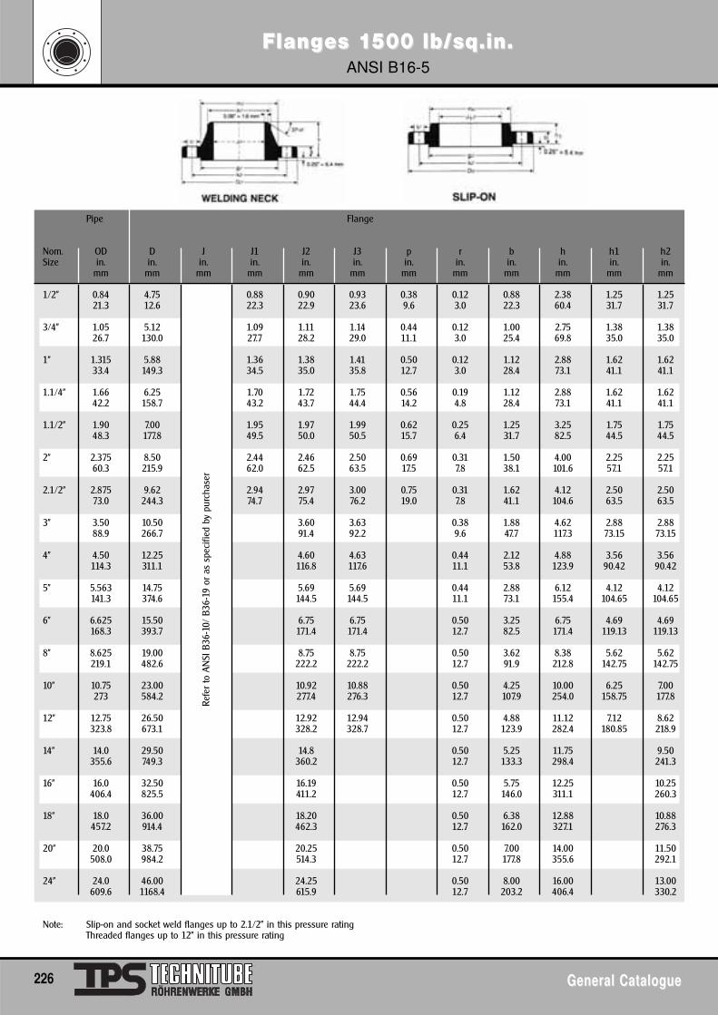
FlangFlanges 1es 1500 lb/sq.in.500 lb/sq.in.ANSI B16-5
226 General CatalogueGeneral Catalogue
Refe
r to
AN
SI B
36-1
0/ B
36-1
9 or
as
spec
ified
by
purc
hase
rPipe Flange
Nom. OD D J J1 J2 J3 p r b h h1 h2Size in. in. in. in. in. in. in. in. in. in. in. in.
mm mm mm mm mm mm mm mm mm mm mm mm
1/2" 0.84 4.75 0.88 0.90 0.93 0.38 0.12 0.88 2.38 1.25 1.2521.3 12.6 22.3 22.9 23.6 9.6 3.0 22.3 60.4 31.7 31.7
3/4" 1.05 5.12 1.09 1.11 1.14 0.44 0.12 1.00 2.75 1.38 1.3826.7 130.0 27.7 28.2 29.0 11.1 3.0 25.4 69.8 35.0 35.0
1" 1.315 5.88 1.36 1.38 1.41 0.50 0.12 1.12 2.88 1.62 1.6233.4 149.3 34.5 35.0 35.8 12.7 3.0 28.4 73.1 41.1 41.1
1.1/4" 1.66 6.25 1.70 1.72 1.75 0.56 0.19 1.12 2.88 1.62 1.6242.2 158.7 43.2 43.7 44.4 14.2 4.8 28.4 73.1 41.1 41.1
1.1/2" 1.90 7.00 1.95 1.97 1.99 0.62 0.25 1.25 3.25 1.75 1.7548.3 177.8 49.5 50.0 50.5 15.7 6.4 31.7 82.5 44.5 44.5
2" 2.375 8.50 2.44 2.46 2.50 0.69 0.31 1.50 4.00 2.25 2.2560.3 215.9 62.0 62.5 63.5 17.5 7.8 38.1 101.6 57.1 57.1
2.1/2" 2.875 9.62 2.94 2.97 3.00 0.75 0.31 1.62 4.12 2.50 2.5073.0 244.3 74.7 75.4 76.2 19.0 7.8 41.1 104.6 63.5 63.5
3" 3.50 10.50 3.60 3.63 0.38 1.88 4.62 2.88 2.8888.9 266.7 91.4 92.2 9.6 47.7 117.3 73.15 73.15
4" 4.50 12.25 4.60 4.63 0.44 2.12 4.88 3.56 3.56114.3 311.1 116.8 117.6 11.1 53.8 123.9 90.42 90.42
5" 5.563 14.75 5.69 5.69 0.44 2.88 6.12 4.12 4.12141.3 374.6 144.5 144.5 11.1 73.1 155.4 104.65 104.65
6" 6.625 15.50 6.75 6.75 0.50 3.25 6.75 4.69 4.69168.3 393.7 171.4 171.4 12.7 82.5 171.4 119.13 119.13
8" 8.625 19.00 8.75 8.75 0.50 3.62 8.38 5.62 5.62219.1 482.6 222.2 222.2 12.7 91.9 212.8 142.75 142.75
10" 10.75 23.00 10.92 10.88 0.50 4.25 10.00 6.25 7.00273 584.2 277.4 276.3 12.7 107.9 254.0 158.75 177.8
12" 12.75 26.50 12.92 12.94 0.50 4.88 11.12 7.12 8.62323.8 673.1 328.2 328.7 12.7 123.9 282.4 180.85 218.9
14" 14.0 29.50 14.8 0.50 5.25 11.75 9.50355.6 749.3 360.2 12.7 133.3 298.4 241.3
16" 16.0 32.50 16.19 0.50 5.75 12.25 10.25406.4 825.5 411.2 12.7 146.0 311.1 260.3
18" 18.0 36.00 18.20 0.50 6.38 12.88 10.88457.2 914.4 462.3 12.7 162.0 327.1 276.3
20" 20.0 38.75 20.25 0.50 7.00 14.00 11.50508.0 984.2 514.3 12.7 177.8 355.6 292.1
24" 24.0 46.00 24.25 0.50 8.00 16.00 13.00609.6 1168.4 615.9 12.7 203.2 406.4 330.2
Note: Slip-on and socket weld flanges up to 2.1/2" in this pressure ratingThreaded flanges up to 12" in this pressure rating
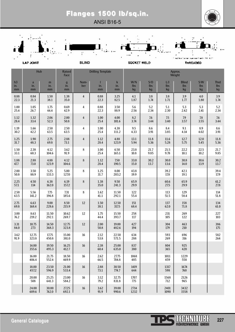
FlangFlanges 1es 1500 lb/sq.in.500 lb/sq.in.ANSI B16-5
General CatalogueGeneral Catalogue 227
Hub Raised Drilling Template Approx.Face Weight
h3 a m g Num- l k W/N S/O L/J Blind S/W Thrdin. in. in. in. ber in. in. lbs lbs lbs lbs lbs lbsmm mm mm mm mm mm kg kg kg kg kg kg
0.88 0.84 1.50 1.38 4 0.88 3.25 4.1 3.8 3.8 3.9 4.0 3.922.3 21.3 38.1 35.0 22.3 82.5 1.87 1.74 1.71 1.77 1.80 1.74
1.00 1.05 1.75 0.69 4 0.88 3.50 5.6 5.2 5.1 5.3 5.3 5.225.4 26.7 44.4 42.9 22.3 88.9 2.56 2.34 2.30 2.42 2.41 2.34
1.12 1.32 2.06 2.00 4 1.00 4.00 8.2 7.6 7.5 7.9 7.8 7.628.4 33.4 52.3 50.8 25.4 101.6 3.74 3.44 3.40 3.57 3.55 3.44
1.19 1.66 2.50 2.50 4 1.00 4.38 9.5 8.6 8.4 9.1 8.9 8.630.2 42.2 63.5 63.5 25.4 111.2 4.33 3.91 3.85 4.14 4.02 3.91
1.25 1.90 2.75 2.88 4 1.12 4.88 13.1 11.8 11.6 12.7 12.0 11.831.7 48.3 69.8 73.1 28.4 123.9 5.94 5.36 5.28 5.75 5.45 5.36
1.50 2.38 4.12 3.62 8 1.00 6.50 23.8 21.7 21.5 22.2 22.5 21.733.1 60.3 104.6 91.9 25.4 165.1 10.8 9.85 9.78 10.1 10.2 9.85
1.88 2.88 4.88 4.12 8 1.12 7.50 33.0 30.2 30.0 30.8 30.6 30.247.7 73.0 123.9 104.6 28.4 190.5 15.0 13.7 13.6 14.0 13.9 13.7
2.00 3.50 5.25 5.00 8 1.25 8.00 43.8 39.2 42.1 39.450.8 88.9 133.3 127.0 31.7 203.2 19.9 17.8 19.1 17.9
2.25 4.50 6.38 6.19 8 1.38 9.50 65.9 60.6 65.9 61.257.1 114 162.0 157.2 35.0 241.3 29.9 27.5 29.9 27.8
2.50 5.56 7.75 7.31 8 1.62 11.50 122 113 129 11463.5 141.2 196.8 185.6 41.1 292.1 55.4 51.5 58.4 51.8
2.75 6.63 9.00 8.50 12 1.50 12.50 151 137 158 13469.8 168.4 228.6 215.9 38.1 317.5 68.4 62.0 71.8 61.0
3.00 8.63 11.50 10.62 12 1.75 15.50 258 231 269 22776.2 219.2 292.1 269.7 44.4 393.7 117 105 122 103
3.31 10.75 14.50 12.75 12 2.00 19.00 427 304 463 38684.0 273 368.3 323.8 50.8 482.6 194 179 210 175
3.62 12.75 17.75 15.00 16 2.12 22.50 634 593 696 58291.9 323.8 450.8 381.0 53.8 571.5 288 269 316 264
14.00 19.50 16.25 16 2.38 25.00 837 804 925355.6 495.3 412.7 60.4 635.0 380 365 420
16.00 21.75 18.50 16 2.62 27.75 1068 1011 1229406.4 552.4 469.9 66.5 704.8 485 459 558
18.00 23.50 21.00 16 2.88 30.50 1419 1317 1674457.2 596.9 533.4 73.1 774.7 644 598 760
20.00 25.25 23.00 16 3.12 32.75 1707 1568 2126508 641.3 584.2 79.2 831.8 775 712 965
24.00 30.00 27.25 16 3.62 39.00 2714 2401 3432609.6 762.0 692.1 91.9 990.6 1232 1090 1558
BLIND
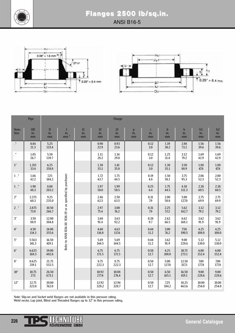
FlangFlanges 2500 lb/sq.in.es 2500 lb/sq.in.ANSI B16-5
228 General CatalogueGeneral Catalogue
Pipe Flange
Nom. OD D J J1 J2 J3 p r b h h1 h2Size in. in. in. in. in. in. in. in. in. in. in. in.
mm mm mm * mm mm mm mm mm mm mm mm mm
_" 0.84 5.25 0.90 0.93 0.12 1.19 2.88 1.56 1.5621.3 133.4 22.9 23.6 3.0 30.2 73.2 39.6 39.6
_" 1.05 5.50 1.11 1.14 0.12 1.25 3.12 1.69 1.6926.7 139.7 28.2 29.0 3.0 31.8 79.2 42.9 42.9
1" 1.315 6.25 1.38 1.41 0.12 1.38 3.50 1.88 1.8833.4 158.8 35.1 35.8 3.0 35.1 88.9 47.8 47.8
1 _" 1.66 7.25 1.72 1.75 0.19 1.50 3.75 2.06 2.0042.2 184.2 43.7 44.5 4.8 38.1 95.3 52.3 52.3
1 _" 1.90 8.00 1.97 1.99 0.25 1.75 4.38 2.38 2.3848.3 203.2 50.0 50.5 6.4 44.5 111.3 60.5 60.5
2" 2.375 9.25 2.46 2.50 0.31 2.00 5.00 2.75 2.7560.3 235.0 62.5 63.5 7.9 50.8 127.0 69.9 69.9
2 _" 2.875 10.50 2.97 3.00 0.31 2.25 5.62 3.12 3.1273.0 266.7 75.4 76.2 7.9 57.2 142.7 79.2 79.2
3" 3.50 12.00 3.60 3.63 0.38 2.62 6.62 3.62 3.6288.9 304.8 91.4 92.2 9.7 66.5 168.1 91.9 91.9
4" 4.50 14.00 4.60 4.63 0.44 3.00 7.50 4.25 4.25114.3 355.6 116.8 117.6 11.2 76.2 190.5 108.0 108.0
5" 5.563 16.50 5.69 5.69 0.44 3.62 9.00 5.12 5.12141.3 419.1 144.5 144.5 11.2 91.9 228.6 130.0 130.0
6" 6.625 19.00 6.75 6.75 0.50 4.25 10.75 6.00 6.00168.3 482.6 171.5 171.5 12.7 108.0 273.1 152.4 152.4
8" 8.625 21.75 8.75 8.75 0.50 5.00 12.50 7.00 7.00219.1 552.5 222.3 222.3 12.7 127.0 317.5 177.8 177.8
10" 10.75 26.50 10.92 10.88 0.50 6.50 16.50 9.00 9.00273 673.1 277.4 276.4 12.7 165.1 419.1 228.6 228.6
12" 12.75 30.00 12.92 12.94 0.50 7.25 18.25 10.00 10.00323.8 762.0 328.2 328.7 12.7 184.2 463.6 254.0 254.0
Note: Slip-on and Socket weld flanges are not available in this pressure rating.Weld necks, Lap joint, Blind and Threaded flanges up to 12" in this pressure rating.
Refe
r to
AN
SI B
36-1
0/ B
36-1
9 or
as
spec
ified
by
purc
hase
r
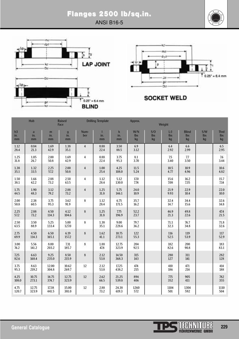
FlangFlanges 2500 lb/sq.in.es 2500 lb/sq.in.ANSI B16-5
General CatalogueGeneral Catalogue 229
Hub Raised Drilling Template Approx.Face Weight
h3 a m g Num- l k W/N S/O L/J Blind S/W Thrdin. in. in. in. ber in. in. lbs lbs lbs lbs lbs lbsmm mm mm mm mm mm kg kg kg kg kg kg
1.12 0.84 1.69 1.38 4 0.88 3.50 6.9 6.4 6.6 6.528.4 21.3 42.9 35.1 22.4 88.5 3.12 2.92 2.99 2.95
1.25 1.05 2.00 1.69 4 0.88 3.75 8.1 7.5 7.7 7.631.8 26.7 50.8 42.9 22.4 95.3 3.70 3.40 3.50 3.44
1.38 1.32 2.25 2.00 4 1.00 4.25 11.5 10.5 10.9 10.635.1 33.5 57.2 50.8 25.4 108.0 5.24 4.77 4.96 4.82
1.50 1.66 2.88 2.50 4 1.12 5.12 17.0 15.6 16.2 15.738.1 42.2 73.2 63.5 28.4 130.0 7.74 7.08 7.35 7.14
1.75 1.90 3.12 2.88 4 1.25 5.75 24.0 21.9 22.9 22.044.5 48.3 79.2 73.2 31.8 146.1 10.9 9.93 10.4 10.0
2.00 2.38 3.75 3.62 8 1.12 6.75 35.7 32.4 34.4 32.650.8 60.5 95.3 91.9 28.4 171.5 16.2 14.7 15.6 14.8
2.25 2.88 4.50 4.12 8 1.25 7.75 52.2 46.9 49.8 47.457.2 73.2 114.3 104.6 31.8 196.9 23.7 21.3 22.6 21.5
2.50 3.50 5.25 5.00 8 1.38 9.00 79.7 71.1 76.7 71.863.5 88.9 133.4 127.0 35.1 228.6 36.2 32.3 34.8 32.6
2.75 4.50 6.50 6.19 8 1.62 10.75 122 116 119 11769.9 114.3 165.1 157.2 41.1 273.1 55.3 52.5 53.9 52.9
3.00 5.56 8.00 7.31 8 1.88 12.75 204 182 200 18376.2 141.2 203.2 185.7 47.8 323.9 92.5 82.6 90.8 83.1
7.25 6.63 9.25 8.50 8 2.12 14.50 315 280 311 28282.6 168.4 235.0 215.9 53.8 368.3 143 127 141 128
3.75 8.63 12.00 10.62 12 2.12 17.25 474 410 471 41495.3 219.2 304.8 269.7 53.8 438.2 215 186 214 188
4.25 10.75 14.75 12.75 12 2.62 21.25 894 775 905 782108.0 273.1 374.7 323.9 66.5 539.8 406 352 411 355
4.75 12.75 17.38 15.00 12 2.88 24.38 1260 1104 1304 1110120.7 323.9 441.5 381.0 73.2 619.3 572 501 592 504
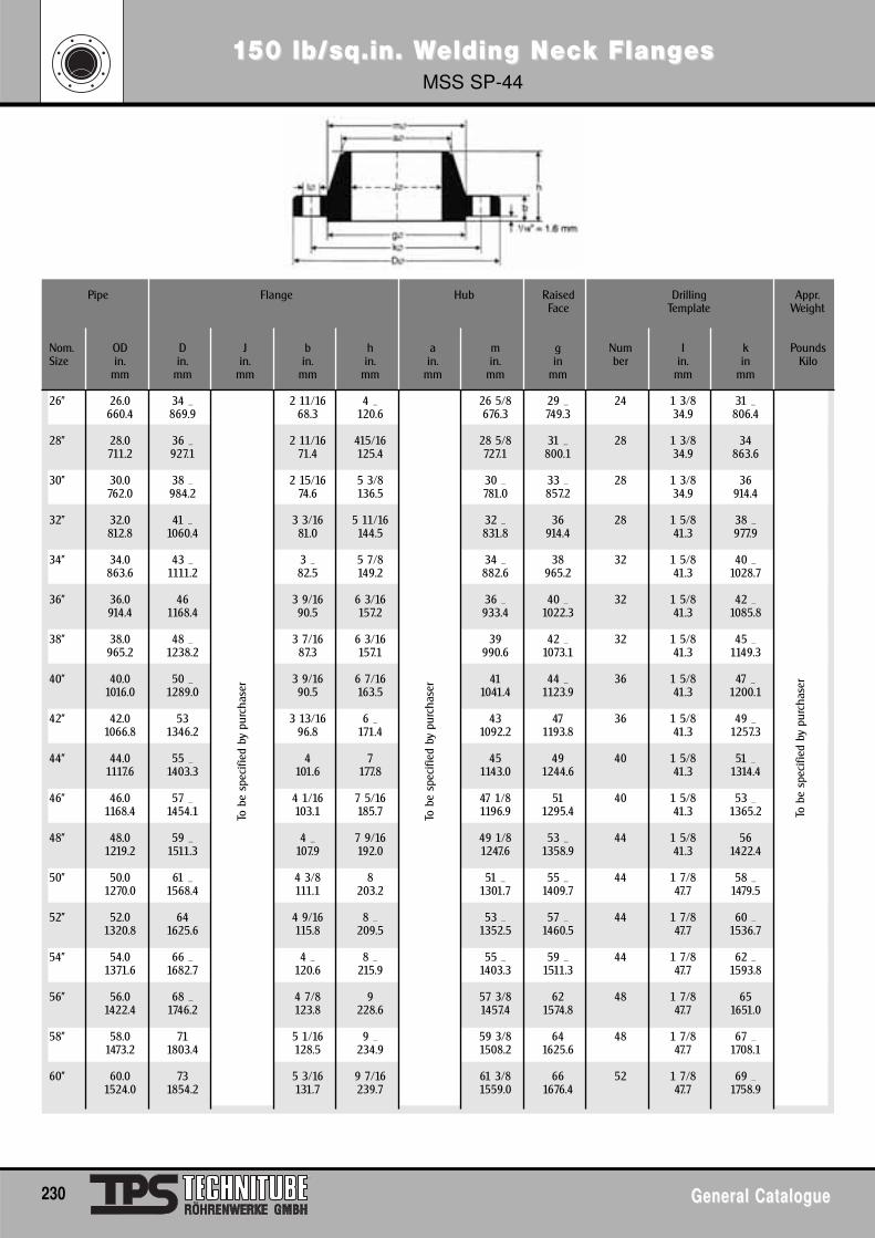
1150 lb/sq.in. W50 lb/sq.in. Welding Nelding Nececk Flangk FlangesesMSS SP-44
230 General CatalogueGeneral Catalogue
Pipe Flange Hub Raised Drilling Appr.Face Template Weight
Nom. OD D J b h a m g Num I k PoundsSize in. in. in. in. in. in. in. in ber in. in Kilo
mm mm mm mm mm mm mm mm mm mm
26" 26.0 34 _ 2 11/16 4 _ 26 5/8 29 _ 24 1 3/8 31 _660.4 869.9 68.3 120.6 676.3 749.3 34.9 806.4
28" 28.0 36 _ 2 11/16 415/16 28 5/8 31 _ 28 1 3/8 34711.2 927.1 71.4 125.4 727.1 800.1 34.9 863.6
30" 30.0 38 _ 2 15/16 5 3/8 30 _ 33 _ 28 1 3/8 36762.0 984.2 74.6 136.5 781.0 857.2 34.9 914.4
32" 32.0 41 _ 3 3/16 5 11/16 32 _ 36 28 1 5/8 38 _812.8 1060.4 81.0 144.5 831.8 914.4 41.3 977.9
34" 34.0 43 _ 3 _ 5 7/8 34 _ 38 32 1 5/8 40 _863.6 1111.2 82.5 149.2 882.6 965.2 41.3 1028.7
36" 36.0 46 3 9/16 6 3/16 36 _ 40 _ 32 1 5/8 42 _914.4 1168.4 90.5 157.2 933.4 1022.3 41.3 1085.8
38" 38.0 48 _ 3 7/16 6 3/16 39 42 _ 32 1 5/8 45 _965.2 1238.2 87.3 157.1 990.6 1073.1 41.3 1149.3
40" 40.0 50 _ 3 9/16 6 7/16 41 44 _ 36 1 5/8 47 _1016.0 1289.0 90.5 163.5 1041.4 1123.9 41.3 1200.1
42" 42.0 53 3 13/16 6 _ 43 47 36 1 5/8 49 _1066.8 1346.2 96.8 171.4 1092.2 1193.8 41.3 1257.3
44" 44.0 55 _ 4 7 45 49 40 1 5/8 51 _1117.6 1403.3 101.6 177.8 1143.0 1244.6 41.3 1314.4
46" 46.0 57 _ 4 1/16 7 5/16 47 1/8 51 40 1 5/8 53 _1168.4 1454.1 103.1 185.7 1196.9 1295.4 41.3 1365.2
48" 48.0 59 _ 4 _ 7 9/16 49 1/8 53 _ 44 1 5/8 561219.2 1511.3 107.9 192.0 1247.6 1358.9 41.3 1422.4
50" 50.0 61 _ 4 3/8 8 51 _ 55 _ 44 1 7/8 58 _1270.0 1568.4 111.1 203.2 1301.7 1409.7 47.7 1479.5
52" 52.0 64 4 9/16 8 _ 53 _ 57 _ 44 1 7/8 60 _1320.8 1625.6 115.8 209.5 1352.5 1460.5 47.7 1536.7
54" 54.0 66 _ 4 _ 8 _ 55 _ 59 _ 44 1 7/8 62 _1371.6 1682.7 120.6 215.9 1403.3 1511.3 47.7 1593.8
56" 56.0 68 _ 4 7/8 9 57 3/8 62 48 1 7/8 651422.4 1746.2 123.8 228.6 1457.4 1574.8 47.7 1651.0
58" 58.0 71 5 1/16 9 _ 59 3/8 64 48 1 7/8 67 _1473.2 1803.4 128.5 234.9 1508.2 1625.6 47.7 1708.1
60" 60.0 73 5 3/16 9 7/16 61 3/8 66 52 1 7/8 69 _1524.0 1854.2 131.7 239.7 1559.0 1676.4 47.7 1758.9
To b
e sp
ecifi
ed b
y pu
rcha
ser
To b
e sp
ecifi
ed b
y pu
rcha
ser
To b
e sp
ecifi
ed b
y pu
rcha
ser
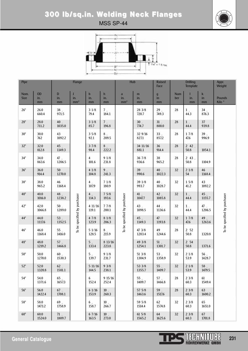
300 lb/sq.in. W300 lb/sq.in. Welding Nelding Nececk Flangk FlangesesMSS SP-44
General CatalogueGeneral Catalogue 231
Pipe Flange Hub Raised Drilling Appr.Face Template Weight
Nom. OD D J b h a m g Num I kSize in. in. in. in. in. in. in. in ber in. in Pounds
mm mm mm* mm mm mm* mm mm mm mm Kilo *
26" 26.0 38 _ 3 1/8 7 _ 28 3/8 29 _ 28 1 _ 34 _660.4 971.5 79.4 184.1 720.7 749.3 44.3 876.3
28" 28.0 40 _ 3 1/8 7 _ 30 _ 31 _ 28 1 _ 37711.2 1035.0 85.7 196.8 774.7 800.0 44.4 939.8
30" 30.0 43 3 5/8 8 _ 32 9/16 33 _ 28 1 7/8 39 _762 1092.2 92.1 209.5 827.1 857.2 47.6 996.9
32" 32.0 45 _ 3 7/8 8 _ 34 11/16 36 28 2 42 _812.8 1149.3 98.4 222.2 881.1 914.4 50.8 1054.1
34" 34.0 47 _ 4 9 1/8 36 7/8 38 28 2 43 _863.6 1206.5 101.6 231.8 936.6 965.2 50.8 1104.9
36" 36.0 50 4 1/8 9 _ 39 40 _ 32 2 1/8 46914.4 1270.0 104.8 241.3 990.6 1022.3 54 1168.4
38" 38.0 46 4 _ 7 1/8 39 1/8 40 _ 32 1 5/8 43965.2 1168.4 107.9 180.9 993.7 1028.7 41.2 1092.2
40" 40.0 48 _ 4 _ 7 5/8 41 _ 42 _ 32 1 _ 45 _1016.0 1238.2 114.3 193.6 1047.7 1085.8 44.4 1155.7
42" 42.0 50 _ 4 11/16 7 7/8 43 _ 44 _ 32 1 _ 47 _1066.8 1289.0 119.1 200.1 1098.5 1136.6 44.4 1206.5
44" 44.0 53 _ 4 7/8 8 1/8 45 _ 47 32 1 7/8 49 _1117.6 1352.5 123.9 206.3 1149.3 1193.8 47.6 1263.6
46" 46.0 55 _ 5 1/16 8 _ 47 3/8 49 28 2 521168.4 1416.0 128.5 215.9 1203.4 1244.6 50.8 1320.8
48" 48.0 57 _ 5 _ 8 13/16 49 3/8 51 _ 32 2 541219.2 1466.8 133.4 223.8 1254.1 1301.7 50.8 1371.6
50" 50.0 60 _ 5 _ 9 1/8 51 3/8 53 _ 32 2 1/8 56 _1270.0 1530.3 139.7 231.7 1304.9 1358.9 53.9 1428.7
52" 52.0 62 _ 5 11/16 9 3/8 53 3/8 55 _ 32 2 1/8 58 _1320.8 1581.1 144.5 238.1 1355.7 1409.7 53.9 1479.5
54" 54.0 65 _ 6 9 15/16 55 _ 57 _ 28 2 3/8 611371.6 1657.3 152.4 252.4 1409.7 1466.8 60.3 1549.4
56" 56.0 67 _ 6 1/16 10 _ 57 5/8 59 _ 28 2 3/8 631422.4 1708.1 153.9 260.3 1463.6 1517.6 60.3 1600.2
58" 58.0 69 _ 6 _ 10 _ 59 5/8 62 32 2 3/8 651473.2 1758.9 158.7 266.7 1514.4 1574.8 60.3 1651.0
60" 60.0 71 _ 6 7/16 10 _ 61 5/8 64 32 2 3/8 671524.0 1809.7 163.5 273.0 1565.2 1625.6 60.3 1701.8
To b
e sp
ecifi
ed b
y pu
rcha
ser
To b
e sp
ecifi
ed b
y pu
rcha
ser
To b
e sp
ecifi
ed b
y pu
rcha
ser
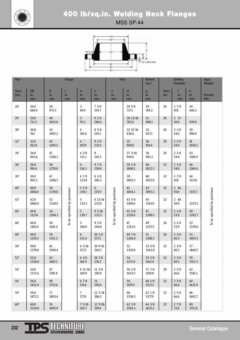
400 lb/sq.in. W400 lb/sq.in. Welding Nelding Nececk Flangk FlangesesMSS SP-44
232 General CatalogueGeneral Catalogue
Pipe Flange Hub Raised Drilling Appr.Face Template Weight
Nom. OD D J b h a m g Num I kSize in. in. in. in. in. in. in. in ber in. in Pounds
mm mm mm mm mm mm mm mm mm mm Kilo
26" 26.0 38 _ 3 _ 7 5/8 28 5/8 29 _ 28 1 7/8 34 _660.4 971.5 88.9 193.7 727.1 749.3 47.6 846.3
28" 28.0 40 _ 3 _ 8 1/8 30 13/16 31 _ 28 2 37711.2 1035.0 95.2 206.4 782.6 800.1 50.8 939.8
30" 30.0 43 4 8 5/8 32 15/16 33 _ 28 2 1/8 39 _762 1092.2 101.6 219.1 836.6 857.2 54.0 996.9
32" 32.0 45 _ 4 _" 9 1/8 35 36 28 2 1/8 41 _812.8 1149.3 107.9 231.8 889.0 914.4 54.0 1054.1
34" 34.0 47 _ 4 3/8 9 _ 37 3/16 38 28 2 1/8 43 _863.6 1206.5 111.1 241.3 944.6 965.2 54.0 1104.9
36" 36.0 50 4 _ 9 7/8 39 1/8 40 _ 32 2 1/8 46914.4 1270.0 114.3 250.8 1000.1 1022.3 54.0 1168.4
38" 38.0 47 _ 4 7/8 8 1/8 39 _ 40 _ 32 1 7/8 44965.2 1206.5 123.8 206.3 1003.3 1035.0 47.6 1117.6
40" 40.0 50 5 1/8 8 _ 41 _ 43 32 2 46 _1016.0 1270.0 130.1 215.9 1054.1 1092.2 50.8 1174.7
42" 42.0 52 5 _ 8 13/16 43 5/8 45 32 2 48 _1066.8 1320.8 133.3 223.8 1108.0 1143.0 50.8 1225.5
44" 44.0 54 _ 5 _ 9 3/16 45 5/8 47 _ 32 2 1/8 50 _1117.6 1384.3 139.7 233.3 1158.8 1200.1 53.9 1282.7
46" 46.0 56 _ 5 _ 9 5/8 47 _ 49 _ 36 2 1/8 52 _1168.4 1441.4 146.0 244.0 1212.8 1257.3 53.9 1339,8
48" 48.0 59 _ 6 10 1/8 49 7/8 51 _ 28 2 3/8 55 _1219.2 1511.3 152.4 257.1 1266.8 1308.1 60.3 1403.3
50" 50.0 61 _ 6 3/16 10 9/16 52 53 5/8 32 2 3/8 57 _1270.0 1568.4 157.2 268.2 1320.8 1362.0 60.3 1460.5
52" 52.0 63 _ 6 3/8 10 7/8 54 55 5/8 32 2 3/8 59 _1320.8 1619.2 161.9 276.2 1371.6 1412.8 60.3 1511.3
54" 54.0 67 6 11/16 11 3/8 56 1/8 57 7/8 28 2 5/8 62 _1371.6 1701.8 169.9 288.9 1425.5 1470.0 66.6 1581.1
56" 56.0 69 6 7/8 11 _ 58 _ 60 1/8 32 2 5/8 64 _1422.4 1752.6 174.6 298.4 1479.5 1527.1 66.6 1631.9
58" 58.0 71 7 12 1/16 60 _ 62 1/8 32 2 5/8 66 _1473.2 1803.4 177.8 306.3 1530.3 1577.9 66.6 1682.7
60" 60.0 74 _ 7 5/16 12 9/16 62 3/8 64 3/8 32 2 7/8 691524.0 1885.9 185.7 319.0 1584.3 1635.1 73.0 1752.6
To b
e sp
ecifi
ed b
y pu
rcha
ser
To b
e sp
ecifi
ed b
y pu
rcha
ser
To b
e sp
ecifi
ed b
y pu
rcha
ser

600 lb/sq.in. W600 lb/sq.in. Welding Nelding Nececk Flangk FlangesesMSS SP-44
General CatalogueGeneral Catalogue 233
Pipe Flange Hub Raised Drilling Appr.Face Template Weight
Nom. OD D J b h a m g Num I kSize in. in. in. in. in. in. in. in ber in. in Pounds
mm mm mm mm mm mm mm mm mm mm Kilo
26" 26.0 40 4 _ 8 _ 29 7/16 29 _ 28 2 36660.4 1016.0 107.9 222.2 747.7 749.3 50.8 914.4
28" 28.0 42 _ 4 3/8 9 _ 31 5/8 31 _ 28 2 1/8 38711.2 1073.1 111.1 234.9 803.3 800.1 54.0 965.2
30" 30.0 44 _ 4 _ 9 _ 33 16/16 33 _ 28 2 1/8 40 _762 1130.3 114.3 247.6 862.0 857.2 54.0 1022.3
32" 32.0 47 4 5/8 10 _ 36 1/8 36 28 2 3/8 42 _812.8 1193.8 117.5 260.3 917.6 914.4 60.3 1079.5
34" 34.0 49 4 _ 10 5/8 38 5/16 38 28 2 3/8 44 _863.6 1244.6 120.6 269.9 973.1 965.2 60.3 1130.3
36" 36.0 51 _ 4 7/8 11 1/8 40 5/8 40 _ 28 2 5/8 47914.4 1314.4 123.8 282.6 1031.9 1022.3 66.7 1193.8
38" 38.0 50 6 10 40 _ 41 _ 28 2 3/8 45 _965.2 1270.0 152.4 254.0 1022.3 1054.1 60.3 1162.0
40" 40.0 52 6 _ 10 3/8 42 _ 43 _ 32 2 3/8 47 _1016.0 1320.8 158.7 263.5 1073.1 1111.2 60.3 1212.8
42" 42.0 55 _ 6 5/8 11 44 3/8 46 28 2 5/8 50 _1066.8 1403.3 168.2 279.4 1127.1 1168.4 66.7 1282.7
44" 44.0 57 _ 6 13/16 11 3/8 46 _ 48 _ 32 2 5/8 52 _1117.6 1554.1 173.0 288.9 1181.1 1225.5 66.7 1333.5
46" 46.0 59 _ 7 1/16 11 13/15 8 5/8 50 _ 32 2 5/8 54 _1168.4 1511.3 179.3 300.0 1235.1 1276.3 66.7 1390.6
48" 48.0 62 _ 7 7/16 12 7/16 50 _ 52 _ 32 2 7/8 57 _1219.2 1593.8 188.9 315.9 1289.0 1333.5 73.0 1460.5
50" 50.0 65 _ 7 _ 12 15/16 50 7/8 54 _ 28 3 1/8 601270.0 1670.0 196.8 328.6 1292.2 1384.3 79.3 1524.0
52" 52.0 67 _ 8 13 _ 54 7/8 56 _ 32 3 1/8 621320.8 1720.8 203.2 336.5 1393.8 1435.1 79.3 1574.8
54" 54.0 70 8 _ 13 _ 57 58 _ 32 3 1/8 64 _1371.6 1778.0 209.5 349.2 1447.8 1492.21 79.3 1631.9
56" 56.0 73 8 9/16 14 _ 59 1/8 60 _ 32 3 3/8 66 _1422.4 1854.2 217.4 361.9 1501.7 1543.0 85.7 1695.4
58" 58.0 75 8 _ 14 9/16 61 1/8 63 32 3 3/8 68 _1473.2 1905.0 222.2 369.8 1552.5 1600.2 85.7 1746.2
60" 60.0 78 _ 9 3/16 15 5/16 63 3/8 65 _ 28 3 5/8 71 _1524.0 1993.9 233.4 388.9 1609.7 1657.3 92.0 1822.4
To b
e sp
ecifi
ed b
y pu
rcha
ser
To b
e sp
ecifi
ed b
y pu
rcha
ser
To b
e sp
ecifi
ed b
y pu
rcha
ser
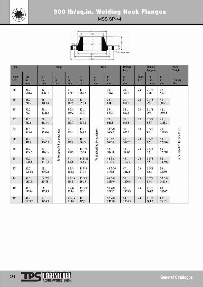
900 lb/sq.in. W900 lb/sq.in. Welding Nelding Nececk Flangk FlangesesMSS SP-44
234 General CatalogueGeneral Catalogue
Pipe Flange Hub Raised Drilling Appr.Face Template Weight
Nom. OD D J b h a m g Num I kSize in. in. in. in. in. in. in. in ber in. in Pounds
mm mm mm mm mm mm mm mm mm mm Kilo
26" 26.0 42 _ 5 _ 11 _ 30 _ 29 _ 20 2 7/8 37 _660.4 1085.8 139.7 285.7 774.4 749.3 73.0 952.5
28" 28.0 46 5 5/8 11 _ 32 _ 31 _ 20 3 1/8 40 _711.2 1168.4 142.9 298.4 831.8 800.1 79.4 1022.3
30" 30.0 48 _ 5 7/8 12 _ 35 33 _ 20 3 1/8 42 _762 1231.9 149.2 311.1 889.0 857.2 79.4 1085.8
32" 32.0 51 _ 6 _ 13 37 _ 36 20 3 3/8 45 _812.8 1314.4 158.7 330.2 946.1 914.4 85.7 1155.7
34" 34.0 55 6 _ 13 _ 39 5/8 38 20 3 5/8 48 _863.6 1397.0 165.1 349.2 1006.5 965.2 92.1 1225.5
36" 36.0 57 _ 6 _ 14 _ 41 7/8 40 _ 20 3 5/8 50 _914.4 1460.5 171.4 361.9 1063.6 1022.3 92.1 1289.0
38" 38.0 57 _ 7 _ 13 7/8 42 _ 43 _ 20 3 5/8 50 _965.2 1460.5 190.5 352.4 1073.1 1098.5 92.1 1289.0
40" 40.0 59 _ 7 _ 14 5/16 44 3/8 45 _ 24 3 5/8 52 _1016.0 1511.3 196.8 363.5 1127.1 1162.0 92.1 1339.8
42" 42.0 61 _ 8 1/8 14 5/8 46 5/16 47 _ 24 3 5/8 54 _1066.8 1562.1 206.3 371.4 1176.3 1212.8 92.1 1390.6
44" 44.0 64 7/8 8 7/16 15 3/8 48 5/8 50 24 3 7/8 57 5/81117.6 1647.8 214.3 390.5 1235.0 1270.0 98.4 1463.6
46" 46.0 68 _ 8 7/8 16 3/16 50 7/8 52 _ 24 4 1/8 60 _1168.4 1733.5 225.4 411.1 1292.2 1333.5 104.7 1536.7
48" 48.0 70 _ 9 3/16 16 _ 52 7/8 54 _ 24 4 1/8 62 _1219.2 1784.3 233.4 419.1 1343.0 1384.3 104.7 1587.5
To b
e sp
ecifi
ed b
y pu
rcha
ser
To b
e sp
ecifi
ed b
y pu
rcha
ser
To b
e sp
ecifi
ed b
y pu
rcha
ser
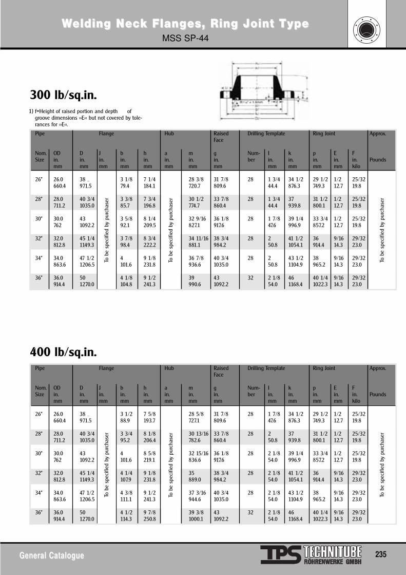
WWelding Nelding Nececk Flangk Flanges, Ring Joint Tes, Ring Joint TypeypeMSS SP-44
General CatalogueGeneral Catalogue 235
Pipe Flange Hub Raised Drilling Template Ring Joint Approx.Face
Nom. OD D J b h a m g Num- I k p E FSize in. in. in. in. in. in. in. in. ber in. in. in. in. in. Pounds
mm mm mm mm mm mm mm mm mm mm mm mm kilo
26" 26.0 38 _ 3 1/8 7 1/4 28 3/8 31 7/8 28 1 3/4 34 1/2 29 1/2 1/2 25/32660.4 971.5 79.4 184.1 720.7 809.6 44.4 876.3 749.3 12.7 19.8
28" 28.0 40 3/4 3 3/8 7 3/4 30 1/2 33 7/8 28 1 3/4 37 31 1/2 1/2 25/32711.2 1035.0 85.7 196.8 774.7 860.4 44.4 939.8 800.1 12.7 19.8
30" 30.0 43 3 5/8 8 1/4 32 9/16 36 1/8 28 1 7/8 39 1/4 33 3/4 1/2 25/32762 1092.2 92.1 209.5 827.1 917.6 47.6 996.9 857.2 12.7 19.8
32" 32.0 45 1/4 3 7/8 8 3/4 34 11/16 38 3/4 28 2 41 1/2 36 9/16 29/32812.8 1149.3 98.4 222.2 881.1 984.2 50.8 1054.1 914.4 14.3 23.0
34" 34.0 47 1/2 4 9 1/8 36 7/8 40 3/4 28 2 43 1/2 38 9/16 29/32863.6 1206.5 101.6 231.8 936.6 1035.0 50.8 1104.9 965.2 14.3 23.0
36" 36.0 50 4 1/8 9 1/2 39 43 32 2 1/8 46 40 1/4 9/16 29/32914.4 1270.0 104.8 241.3 990.6 1092.2 54.0 1168.4 1022.3 14.3 23.0
1) f=Height of raised portion and depth ofgroove dimensions >>E<< but not covered by tole-rances for >>E<<.
Pipe Flange Hub Raised Drilling Template Ring Joint Approx.Face
Nom. OD D J b h a m g Num- I k p E FSize in. in. in. in. in. in. in. in. ber in. in. in. in. in. Pounds
mm mm mm mm mm mm mm mm mm mm mm mm kilo
26" 26.0 38 _ 3 1/2 7 5/8 28 5/8 31 7/8 28 1 7/8 34 1/2 29 1/2 1/2 25/32660.4 971.5 88.9 193.7 727.1 809.6 47.6 876.3 749.3 12.7 19.8
28" 28.0 40 3/4 3 3/4 8 1/8 30 13/16 33 7/8 28 2 37 31 1/2 1/2 25/32711.2 1035.0 95.2 206.4 782.6 860.4 50.8 939.8 800.1 12.7 19.8
30" 30.0 43 4 8 5/8 32 15/16 36 1/8 28 2 1/8 39 1/4 33 3/4 1/2 25/32762 1092.2 101.6 219.1 836.6 917.6 54.0 996.9 857.2 12.7 19.8
32" 32.0 45 1/4 4 1/4 9 1/8 35 38 3/4 28 2 1/8 41 1/2 36 9/16 29/32812.8 1149.3 107.9 231.8 889.0 984.2 54.0 1054.1 914.4 14.3 23.0
34" 34.0 47 1/2 4 3/8 9 1/2 37 3/16 40 3/4 28 2 1/8 43 1/2 38 9/16 29/32863.6 1206.5 111.1 241.3 944.6 1035.0 54.0 1104.9 965.2 14.3 23.0
36" 36.0 50 4 1/2 9 7/8 39 3/8 43 32 2 1/8 46 40 1/4 9/16 29/32914.4 1270.0 114.3 250.8 1000.1 1092.2 54.0 1168.4 1022.3 14.3 23.0
400 lb/sq.in.
300 lb/sq.in.To
be
spec
ified
by
purc
hase
rTo
be
spec
ified
by
purc
hase
r
To b
e sp
ecifi
ed b
y pu
rcha
ser
To b
e sp
ecifi
ed b
y pu
rcha
ser
To b
e sp
ecifi
ed b
y pu
rcha
ser
To b
e sp
ecifi
ed b
y pu
rcha
ser
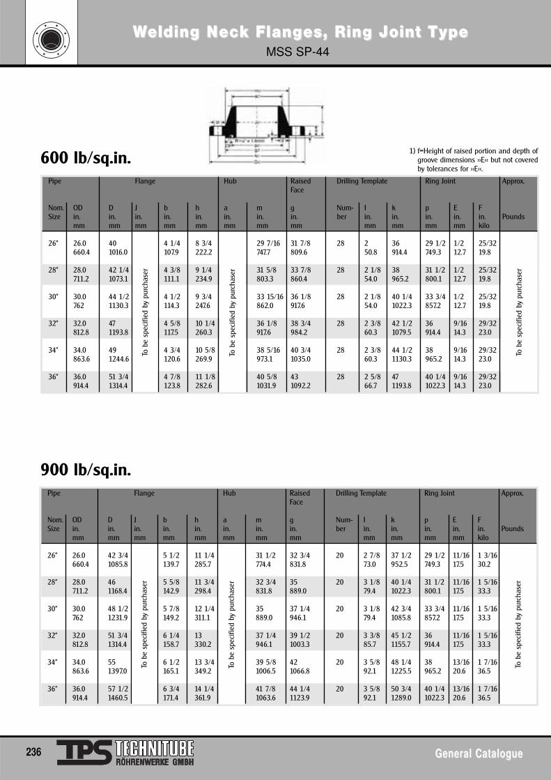
WWelding Nelding Nececk Flangk Flanges, Ring Joint Tes, Ring Joint TypeypeMSS SP-44
236 General CatalogueGeneral Catalogue
Pipe Flange Hub Raised Drilling Template Ring Joint Approx.Face
Nom. OD D J b h a m g Num- I k p E FSize in. in. in. in. in. in. in. in. ber in. in. in. in. in. Pounds
mm mm mm mm mm mm mm mm mm mm mm mm kilo
26" 26.0 40 4 1/4 8 3/4 29 7/16 31 7/8 28 2 36 29 1/2 1/2 25/32660.4 1016.0 107.9 222.2 747.7 809.6 50.8 914.4 749.3 12.7 19.8
28" 28.0 42 1/4 4 3/8 9 1/4 31 5/8 33 7/8 28 2 1/8 38 31 1/2 1/2 25/32 *711.2 1073.1 *** 111.1 234.9 ** 803.3 860.4 54.0 965.2 800.1 12.7 19.8
30" 30.0 44 1/2 4 1/2 9 3/4 33 15/16 36 1/8 28 2 1/8 40 1/4 33 3/4 1/2 25/32762 1130.3 114.3 247.6 862.0 917.6 54.0 1022.3 857.2 12.7 19.8
32" 32.0 47 4 5/8 10 1/4 36 1/8 38 3/4 28 2 3/8 42 1/2 36 9/16 29/32812.8 1193.8 117.5 260.3 917.6 984.2 60.3 1079.5 914.4 14.3 23.0
34" 34.0 49 4 3/4 10 5/8 38 5/16 40 3/4 28 2 3/8 44 1/2 38 9/16 29/32863.6 1244.6 120.6 269.9 973.1 1035.0 60.3 1130.3 965.2 14.3 23.0
36" 36.0 51 3/4 4 7/8 11 1/8 40 5/8 43 28 2 5/8 47 40 1/4 9/16 29/32914.4 1314.4 123.8 282.6 1031.9 1092.2 66.7 1193.8 1022.3 14.3 23.0
To b
e sp
ecifi
ed b
y pu
rcha
ser
To b
e sp
ecifi
ed b
y pu
rcha
ser
To b
e sp
ecifi
ed b
y pu
rcha
ser
1) f=Height of raised portion and depth ofgroove dimensions >>E<< but not coveredby tolerances for >>E<<.
Pipe Flange Hub Raised Drilling Template Ring Joint Approx.Face
Nom. OD D J b h a m g Num- I k p E FSize in. in. in. in. in. in. in. in. ber in. in. in. in. in. Pounds
mm mm mm mm mm mm mm mm mm mm mm mm kilo
26" 26.0 42 3/4 5 1/2 11 1/4 31 1/2 32 3/4 20 2 7/8 37 1/2 29 1/2 11/16 1 3/16660.4 1085.8 139.7 285.7 774.4 831.8 73.0 952.5 749.3 17.5 30.2
28" 28.0 46 5 5/8 11 3/4 32 3/4 35 20 3 1/8 40 1/4 31 1/2 11/16 1 5/16711.2 1168.4 *** 142.9 298.4 ** 831.8 889.0 79.4 1022.3 800.1 17.5 33.3
30" 30.0 48 1/2 5 7/8 12 1/4 35 37 1/4 20 3 1/8 42 3/4 33 3/4 11/16 1 5/16762 1231.9 149.2 311.1 889.0 946.1 79.4 1085.8 857.2 17.5 33.3
32" 32.0 51 3/4 6 1/4 13 37 1/4 39 1/2 20 3 3/8 45 1/2 36 11/16 1 5/16812.8 1314.4 158.7 330.2 946.1 1003.3 85.7 1155.7 914.4 17.5 33.3
34" 34.0 55 6 1/2 13 3/4 39 5/8 42 20 3 5/8 48 1/4 38 13/16 1 7/16863.6 1397.0 165.1 349.2 1006.5 1066.8 92.1 1225.5 965.2 20.6 36.5
36" 36.0 57 1/2 6 3/4 14 1/4 41 7/8 44 1/4 20 3 5/8 50 3/4 40 1/4 13/16 1 7/16914.4 1460.5 171.4 361.9 1063.6 1123.9 92.1 1289.0 1022.3 20.6 36.5
900 lb/sq.in.
600 lb/sq.in. To
be
spec
ified
by
purc
hase
r
To b
e sp
ecifi
ed b
y pu
rcha
ser
To b
e sp
ecifi
ed b
y pu
rcha
ser
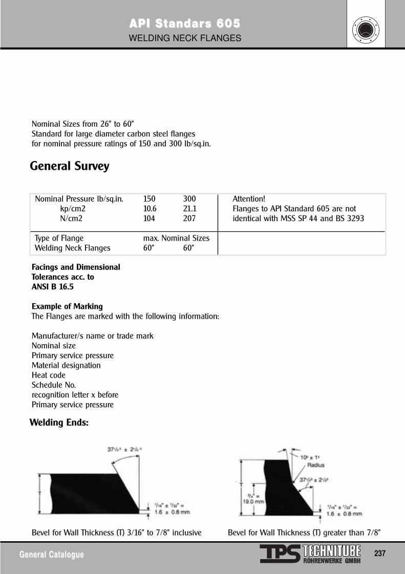
API SAPI Sttandarandars 605s 605WELDING NECK FLANGES
General CatalogueGeneral Catalogue 237
General Survey
Welding Ends:
Nominal Sizes from 26" to 60"Standard for large diameter carbon steel flangesfor nominal pressure ratings of 150 and 300 lb/sq.in.
Facings and DimensionalTolerances acc. to ANSI B 16.5
Example of MarkingThe Flanges are marked with the following information:
Manufacturer/s name or trade markNominal sizePrimary service pressureMaterial designationHeat codeSchedule No.recognition letter x beforePrimary service pressure
Bevel for Wall Thickness (T) 3/16" to 7/8" inclusive Bevel for Wall Thickness (T) greater than 7/8"
Nominal Pressure lb/sq.in. 150 300 Attention!kp/cm2 10.6 21.1 Flanges to API Standard 605 are notN/cm2 104 207 identical with MSS SP 44 and BS 3293
Type of Flange max. Nominal SizesWelding Neck Flanges 60" 60"
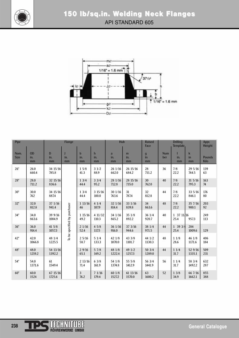
1150 lb/sq.in. W50 lb/sq.in. Welding Nelding Nececk Flangk FlangesesAPI STANDARD 605
238 General CatalogueGeneral Catalogue
Pipe Flange Hub Raised Drilling Appr.Face Template Weight
Nom. OD D J b h a m g Num I kSize in. in. in. in. in. in. in. in ber in. in Pounds
mm mm mm mm mm mm mm mm mm mm Kilo
26" 26.0 34 15/16 1 5/8 3 1/2 26 1/16 26 15/16 28 36 7/8 29 5/16 139660.4 785.8 41.3 88.9 662.0 684.2 711.2 22.2 744.5 63
28" 28.0 32 15/16 1 3/4 3 3/4 28 1/16 28 15/16 30 40 7/8 31 5/16 163711.2 836.6 44.4 95.2 712.8 735.0 762.0 22.2 795.3 74
30" 30.0 34 15/16 1 3/4 3 15/16 30 1/16 31 32 44 7/8 33 5/16 176762 887.4 44.4 100.0 763.6 787.4 812.8 22.2 846.1 80
32" 32.0 37 1/16 1 13/16 4 1/4 32 1/16 33 1/16 34 48 7/8 35 7/16 203812.8 941.4 46 107.9 814.4 839.8 863.6 22.2 900.1 92
34" 34.0 39 9/16 1 15/16 4 11/32 34 1/16 35 1/8 36 1/4 40 1 37 11/16 249863.6 1004.9 49.2 110.3 865.2 892.2 920.7 25.4 957.3 113
36" 36.0 41 5/8 2 1/16 4 5/8 36 1/16 37 3/16 38 1/4 44 1 39 3/4 284914.4 1057.3 52.4 117.5 916.0 944.6 971.5 25.4 1009.6 129
42" 42.0 48 1/4 2 5/16 5 1/4 42 1/8 43 3/8 44 1/2 48 1 1/8 46 1/8 4061066.8 1225.5 58.7 133.3 1070.0 1101.7 1130.3 28.6 1171.6 184
48" 48.0 54 13/16 2 9/16 5 7/8 48 1/8 49 1/2 50 3/4 44 1 1/4 52 9/16 5091219.2 1392.2 65.1 149.2 1222.4 1257.3 1289.0 31.7 1335.1 231
54" 54.0 61 2 13/16 6 3/8 54 1/8 55 5/8 56 3/4 56 1 1/4 58 3/4 6321371.6 1549.4 71.4 161.9 1374.8 1412.9 1441.9 31.7 1492.2 287
60" 60.0 67 15/16 3 7 1/16 60 1/8 61 13/16 63 52 1 3/8 66 7/16 8551524 1725.6 76.2 179.4 1527.2 1570.0 1600.2 34.9 1662.1 388
To b
e sp
ecifi
ed b
y pu
rcha
ser
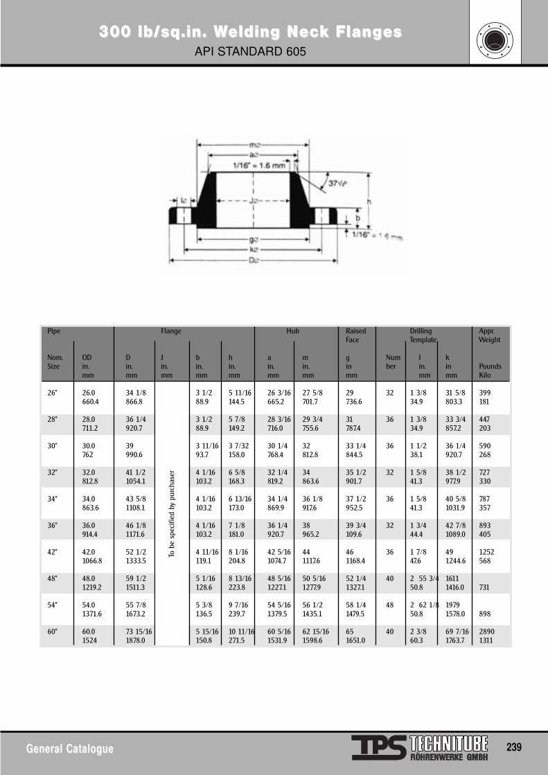
300 lb/sq.in. W300 lb/sq.in. Welding Nelding Nececk Flangk FlangesesAPI STANDARD 605
General CatalogueGeneral Catalogue 239
Pipe Flange Hub Raised Drilling Appr.Face Template Weight
Nom. OD D J b h a m g Num I kSize in. in. in. in. in. in. in. in ber in. in Pounds
mm mm mm mm mm mm mm mm mm mm Kilo
26" 26.0 34 1/8 3 1/2 5 11/16 26 3/16 27 5/8 29 32 1 3/8 31 5/8 399660.4 866.8 88.9 144.5 665.2 701.7 736.6 34.9 803.3 181
28" 28.0 36 1/4 3 1/2 5 7/8 28 3/16 29 3/4 31 36 1 3/8 33 3/4 447711.2 920.7 88.9 149.2 716.0 755.6 787.4 34.9 857.2 203
30" 30.0 39 3 11/16 3 7/32 30 1/4 32 33 1/4 36 1 1/2 36 1/4 590762 990.6 93.7 158.0 768.4 812.8 844.5 38.1 920.7 268
32" 32.0 41 1/2 * 4 1/16 6 5/8 32 1/4 34 35 1/2 32 1 5/8 38 1/2 727812.8 1054.1 103.2 168.3 819.2 863.6 901.7 41.3 977.9 330
34" 34.0 43 5/8 4 1/16 6 13/16 34 1/4 36 1/8 37 1/2 36 1 5/8 40 5/8 787863.6 1108.1 103.2 173.0 869.9 917.6 952.5 41.3 1031.9 357
36" 36.0 46 1/8 4 1/16 7 1/8 36 1/4 38 39 3/4 32 1 3/4 42 7/8 893914.4 1171.6 103.2 181.0 920.7 965.2 109.6 44.4 1089.0 405
42" 42.0 52 1/2 4 11/16 8 1/16 42 5/16 44 46 36 1 7/8 49 12521066.8 1333.5 119.1 204.8 1074.7 1117.6 1168.4 47.6 1244.6 568
48" 48.0 59 1/2 5 1/16 8 13/16 48 5/16 50 5/16 52 1/4 40 2 55 3/4 16111219.2 1511.3 128.6 223.8 1227.1 1277.9 1327.1 50.8 1416.0 731
54" 54.0 55 7/8 5 3/8 9 7/16 54 5/16 56 1/2 58 1/4 48 2 62 1/8 19791371.6 1673.2 136.5 239.7 1379.5 1435.1 1479.5 50.8 1578.0 898
60" 60.0 73 15/16 5 15/16 10 11/16 60 5/16 62 15/16 65 40 2 3/8 69 7/16 28901524 1878.0 150.8 271.5 1531.9 1598.6 1651.0 60.3 1763.7 1311
To b
e sp
ecifi
ed b
y pu
rcha
ser
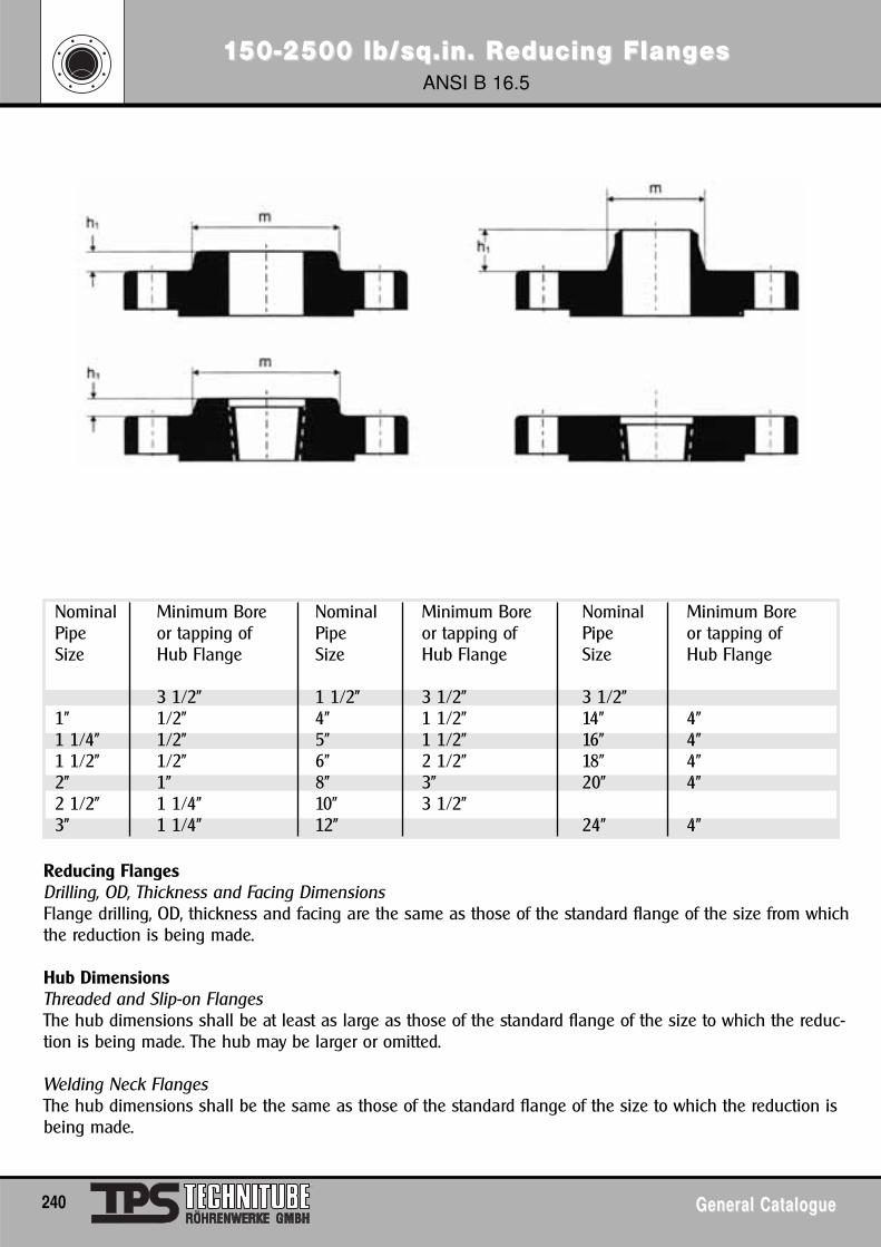
1150-2500 lb/sq.in. R50-2500 lb/sq.in. Reducing Flangeducing FlangesesANSI B 16.5
240 General CatalogueGeneral Catalogue
Nominal Minimum Bore Nominal Minimum Bore Nominal Minimum BorePipe or tapping of Pipe or tapping of Pipe or tapping ofSize Hub Flange Size Hub Flange Size Hub Flange
3 1/2" 1 1/2" 3 1/2" 3 1/2"1" 1/2" 4" 1 1/2" 14" 4"1 1/4" 1/2" 5" 1 1/2" 16" 4"1 1/2" 1/2" 6" 2 1/2" 18" 4"2" 1" 8" 3" 20" 4"2 1/2" 1 1/4" 10" 3 1/2"3" 1 1/4" 12" 24" 4"
Reducing FlangesDrilling, OD, Thickness and Facing DimensionsFlange drilling, OD, thickness and facing are the same as those of the standard flange of the size from whichthe reduction is being made.
Hub DimensionsThreaded and Slip-on FlangesThe hub dimensions shall be at least as large as those of the standard flange of the size to which the reduc-tion is being made. The hub may be larger or omitted.
Welding Neck FlangesThe hub dimensions shall be the same as those of the standard flange of the size to which the reduction isbeing made.
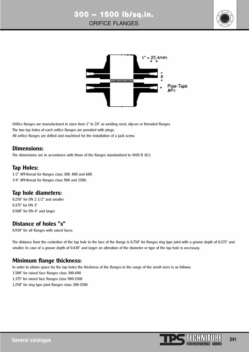
300 – 1300 – 1500 lb/sq.in.500 lb/sq.in.ORIFICE FLANGES
General catalogueGeneral catalogue 241
Orifice flanges are manufactured in sizes from 1" to 24" as welding neck, slip-on or threaded flanges.
The two tap holes of each orifice flanges are provided with plugs.
All orifice flanges are drilled and machined for the installation of a jack screw.
Dimensions: The dimensions are in accordance with those of the flanges standardized to ANSI B 16.5.
Tap Holes: 1/2" API-thread for flanges class 300, 400 and 600.
3/4" API-thread for flanges class 900 and 1500.
Tap hole diameters: 0.250" for DN 2 1/2" and smaller
0.375" for DN 3"
0.500" for DN 4" and larger
Distance of holes "x" 0.938" for all flanges with raised faces.
The distance from the centerline of the tap hole to the face of the flange is 0.750" for flanges ring type joint with a groove depth of 0.375" and
smaller. In case of a groove depth of 0.438" and larger an alteration of the diameter or type of the tap hole is necessary.
Minimum flange thickness: In order to obtain space for the tap holes the thickness of the flanges in the range of the small sizes is as follows:
1.500" for raised face flanges class 300-600
1.375" for raised face flanges class 900-1500
1.250" for ring type joint flanges class 300-1500.
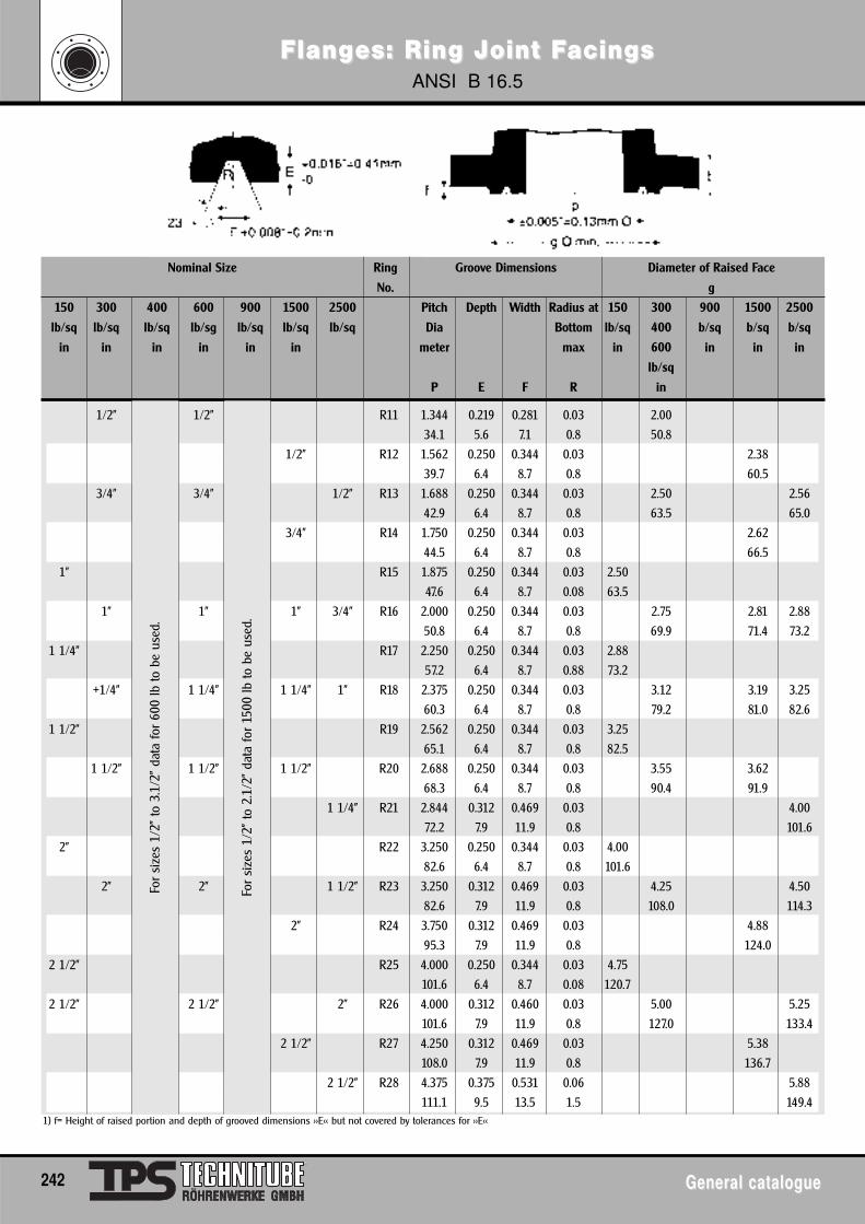
FlangFlanges: Ring Joint Fes: Ring Joint Facings acings ANSI B 16.5
242 General catalogueGeneral catalogue
Nominal Size Ring Groove Dimensions Diameter of Raised Face
No. g
150 300 400 600 900 1500 2500 Pitch Depth Width Radius at 150 300 900 1500 2500
lb/sq lb/sq lb/sq lb/sg lb/sq lb/sq lb/sq Dia Bottom lb/sq 400 b/sq b/sq b/sq
in in in in in in meter max in 600 in in in
lb/sq
P E F R in
1/2" 1/2" R11 1.344 0.219 0.281 0.03 2.00
34.1 5.6 7.1 0.8 50.8
1/2" R12 1.562 0.250 0.344 0.03 2.38
39.7 6.4 8.7 0.8 60.5
3/4" 3/4" 1/2" R13 1.688 0.250 0.344 0.03 2.50 2.56
42.9 6.4 8.7 0.8 63.5 65.0
3/4" R14 1.750 0.250 0.344 0.03 2.62
44.5 6.4 8.7 0.8 66.5
1" R15 1.875 0.250 0.344 0.03 2.50
47.6 6.4 8.7 0.08 63.5
1" 1" 1" 3/4" R16 2.000 0.250 0.344 0.03 2.75 2.81 2.88
50.8 6.4 8.7 0.8 69.9 71.4 73.2
1 1/4" R17 2.250 0.250 0.344 0.03 2.88
57.2 6.4 8.7 0.88 73.2
+1/4" 1 1/4" 1 1/4" 1" R18 2.375 0.250 0.344 0.03 3.12 3.19 3.25
60.3 6.4 8.7 0.8 79.2 81.0 82.6
1 1/2" R19 2.562 0.250 0.344 0.03 3.25
65.1 6.4 8.7 0.8 82.5
1 1/2" 1 1/2" 1 1/2" R20 2.688 0.250 0.344 0.03 3.55 3.62
68.3 6.4 8.7 0.8 90.4 91.9
1 1/4" R21 2.844 0.312 0.469 0.03 4.00
72.2 7.9 11.9 0.8 101.6
2" R22 3.250 0.250 0.344 0.03 4.00
82.6 6.4 8.7 0.8 101.6
2" 2" 1 1/2" R23 3.250 0.312 0.469 0.03 4.25 4.50
82.6 7.9 11.9 0.8 108.0 114.3
2" R24 3.750 0.312 0.469 0.03 4.88
95.3 7.9 11.9 0.8 124.0
2 1/2" R25 4.000 0.250 0.344 0.03 4.75
101.6 6.4 8.7 0.08 120.7
2 1/2" 2 1/2" 2" R26 4.000 0.312 0.460 0.03 5.00 5.25
101.6 7.9 11.9 0.8 127.0 133.4
2 1/2" R27 4.250 0.312 0.469 0.03 5.38
108.0 7.9 11.9 0.8 136.7
2 1/2" R28 4.375 0.375 0.531 0.06 5.88
111.1 9.5 13.5 1.5 149.4
For
size
s 1/
2" to
3.1
/2"
data
for
600
lb to
be
used
.
For
size
s 1/
2" to
2.1
/2"
data
for
1500
lb to
be
used
.
1) f= Height of raised portion and depth of grooved dimensions >>E<< but not covered by tolerances for >>E<<
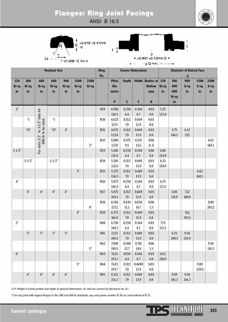
FlangFlanges: Ring Joint Fes: Ring Joint Facings acings ANSI B 16.5
General catalogueGeneral catalogue 243
Nominal Size Ring Groove Dimensions Diameter of Raised Face
No. g
150 300 400 600 900 1500 2500 Pitch Depth Width Radius at 150 300 900 1500 2500
lb/sq lb/sq lb/sq lb/sg lb/sq lb/sq lb/sq Dia Bottom lb/sq 400 b/sq b/sq b/sq
in in in in in in meter max in 600 in in in
lb/sq
P E F R in
3" R29 4.500 0.250 0.344 0.03 5.25
114.3 6.4 8.7 0.8 133.4
*) *) R30 4.625 0.312 0.469 0.03
117.5 7.9 11.9 0.8
*)3" *)3" 3" R31 4.875 0.312 0.469 0.03 5.75 6.12
123.8 7.9 11.9 0.8 146.1 155
R32 5.000 0.375 0.531 0.06 6.62
3" 127.0 9.5 13.5 0. 8 168.1
3 1/2" R33 5.188 0.250 0.344 0.06 6.06
131.8 6.4 8.7 0.8 153.9
3 1/2" 3 1/2" R34 5.188 0.312 0.469 0.03 6.25
131.8 7.9 11.9 0.8 158.8
3" R35 5.375 0.312 0.469 0.03 6.62
136.5 7.9 11.9 0.8 168.1
4" R36 5.875 0.250 0.344 0.03 6.75
149.2 6.4 8.7 0.8 171.5
4" 4" 4" 4" R37 5.875 0.312 0.469 0.03 6.88 7.12
149.2 7.9 11.9 0.8 174.8 180.8
R38 6.188 0.438 0.656 0.06 8.00
4" 157.2 11.1 16.7 1.5 203.2
4" R39 6.375 0.312 0.469 0.03 7.62
161.9 7.9 11.9 0.8 193.5
5" R40 6.750 0.250 0.344 0.03 7.75
149.2 6.4 8.7 0.8 171.5
5" 5" 5" 5" R41 7.125 0.312 0.469 0.03 8.25 8.50
149.2 7.9 11.9 0.8 209.5 215.9
R42 7.500 0.500 0.781 0.06 9.50
5" 190.5 12.7 19.8 1.5 241.3
6" R43 7.625 0250 0.344 0.03 8.62
193.7 6.4 8.7 0.8 218.9
5" R44 7.625 0.312 0.4690 0.03 9.00
193.7 7.9 11.9 0.8 228.6
6" 6" 6" 6" R45 8.312 0.312 0.469 0.03 9.50 9.50
211.1 7.9 11.9 0.8 241.3 241.3
For
size
s 1/
2"
to 3
.1/2
" da
ta fo
r60
0 lb
to b
e us
ed.
1) f= Height of raised portion and depth of grooved dimensions >>E<< but not covered by tolerances for >>E<<
*) For ring joint with lapped flanges in the 300 and 600 lb standards, nng and groove number R 30 are used instead of R 31.
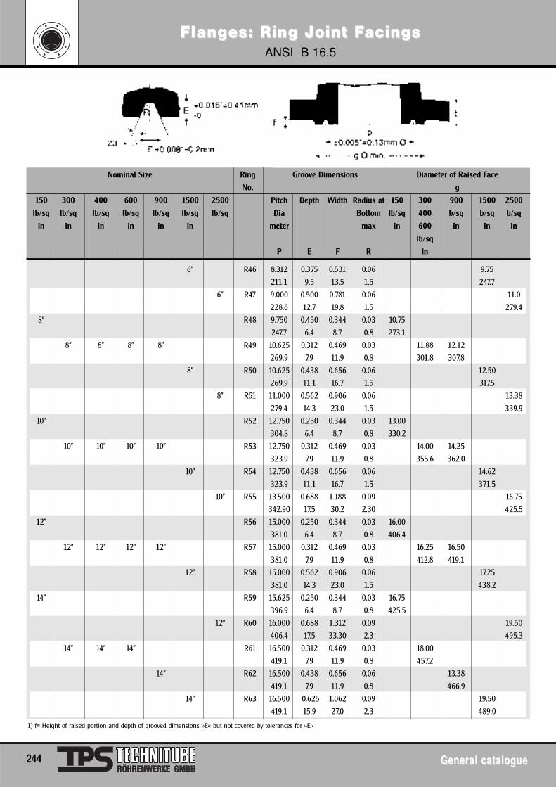
FlangFlanges: Ring Joint Fes: Ring Joint Facings acings ANSI B 16.5
244 General catalogueGeneral catalogue
Nominal Size Ring Groove Dimensions Diameter of Raised Face
No. g
150 300 400 600 900 1500 2500 Pitch Depth Width Radius at 150 300 900 1500 2500
lb/sq lb/sq lb/sq lb/sg lb/sq lb/sq lb/sq Dia Bottom lb/sq 400 b/sq b/sq b/sq
in in in in in in meter max in 600 in in in
lb/sq
P E F R in
6" R46 8.312 0.375 0.531 0.06 9.75
211.1 9.5 13.5 1.5 247.7
6" R47 9.000 0.500 0.781 0.06 11.0
228.6 12.7 19.8 1.5 279.4
8" R48 9.750 0.450 0.344 0.03 10.75
247.7 6.4 8.7 0.8 273.1
8" 8" 8" 8" R49 10.625 0.312 0.469 0.03 11.88 12.12
269.9 7.9 11.9 0.8 301.8 307.8
8" R50 10.625 0.438 0.656 0.06 12.50
269.9 11.1 16.7 1.5 317.5
8" R51 11.000 0.562 0.906 0.06 13.38
279.4 14.3 23.0 1.5 339.9
10" R52 12.750 0.250 0.344 0.03 13.00
304.8 6.4 8.7 0.8 330.2
10" 10" 10" 10" R53 12.750 0.312 0.469 0.03 14.00 14.25
323.9 7.9 11.9 0.8 355.6 362.0
10” R54 12.750 0.438 0.656 0.06 14.62
323.9 11.1 16.7 1.5 371.5
10" R55 13.500 0.688 1.188 0.09 16.75
342.90 17.5 30.2 2.30 425.5
12” R56 15.000 0.250 0.344 0.03 16.00
381.0 6.4 8.7 0.8 406.4
12" 12" 12" 12" R57 15.000 0.312 0.469 0.03 16.25 16.50
381.0 7.9 11.9 0.8 412.8 419.1
12” R58 15.000 0.562 0.906 0.06 17.25
381.0 14.3 23.0 1.5 438.2
14” R59 15.625 0.250 0.344 0.03 16.75
396.9 6.4 8.7 0.8 425.5
12" R60 16.000 0.688 1.312 0.09 19.50
406.4 17.5 33.30 2.3 495.3
14" 14" 14" R61 16.500 0.312 0.469 0.03 18.00
419.1 7.9 11.9 0.8 457.2
14” R62 16.500 0.438 0.656 0.06 13.38
419.1 7.9 11.9 0.8 466.9
14" R63 16.500 0.625 1.062 0.09 19.50
419.1 15.9 27.0 2.3 489.0
1) f= Height of raised portion and depth of grooved dimensions >>E<< but not covered by tolerances for >>E<<
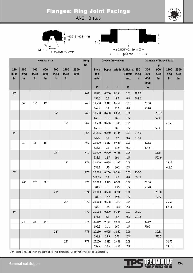
FlangFlanges: Ring Joint Fes: Ring Joint Facings acings ANSI B 16.5
General catalogueGeneral catalogue 245
Nominal Size Ring Groove Dimensions Diameter of Raised Face
No. g
150 300 400 600 900 1500 2500 Pitch Depth Width Radius at 150 300 900 1500 2500
lb/sq lb/sq lb/sq lb/sg lb/sq lb/sq lb/sq Dia Bottom lb/sq 400 b/sq b/sq b/sq
in in in in in in meter max in 600 in in in
lb/sq
P E F R in
16” R64 17.875 0.250 0.344 0.03 19.00
454.0 6.4 8.7 0.8 482.6
16" 16" 16" R65 18.500 0.312 0.469 0.03 20.00
469.9 7.9 11.9 0.8 508.0
16” R66 18.500 0.438 0.656 0.06 20.62
469.9 11.1 16.7 1.5 523.7
16" R67 18.500 0.688 1.188 0.09 21.50
469.9 11.1 16.7 1.5 523.7
18” R68 20.375 0.250 0.344 0.03 21.50
517.5 6.4 8.7 0.8 546.1
18" 18" 18" R69 21.000 0.312 0.469 0.03 22.62
533.4 7.9 11.9 0.8 574.5
18” R70 21.000 0.500 0.781 0.06 23.38
533.4 12.7 19.8 1.5 593.9
18" R71 21.000 0.688 1.188 0.09 24.12
533.4 17.5 30.2 2.3 612.6
20” R72 22.000 0.250 0.344 0.03 23.50
558.86 6.4 8.7 0.8 596.9
20" 20" 20" R73 23.000 0.375 0.531 0.06 25.00
584.2 9.5 13.5 1.5 635.0
20” R74 23.000 0.500 0.781 0.06 25.50
584.2 12.7 19.8 1.5 647.7
20" R75 23.000 0.688 1.312 0.09 26.50
584.2 17.5 33.3 2.3 673.1
24” R76 26.500 0.250 0.344 0.03 28.20
673.1 6.4 8.7 0.8 711.2
24" 24" 24" R77 27.250 0.438 0.656 0.06 29.50
692.2 11.1 16.7 1.5 749.3
24” R78 27.250 0.625 1.062 0.09 30.38
692.2 15.9 27.0 2.3 771.7
24" R79 27.250 0.812 1.438 0.09 31.75
692.2 20.6 36.50 2.3 793.8
1) f= Height of raised portion and depth of grooved dimensions >>E<< but not covered by tolerances for >>E<<
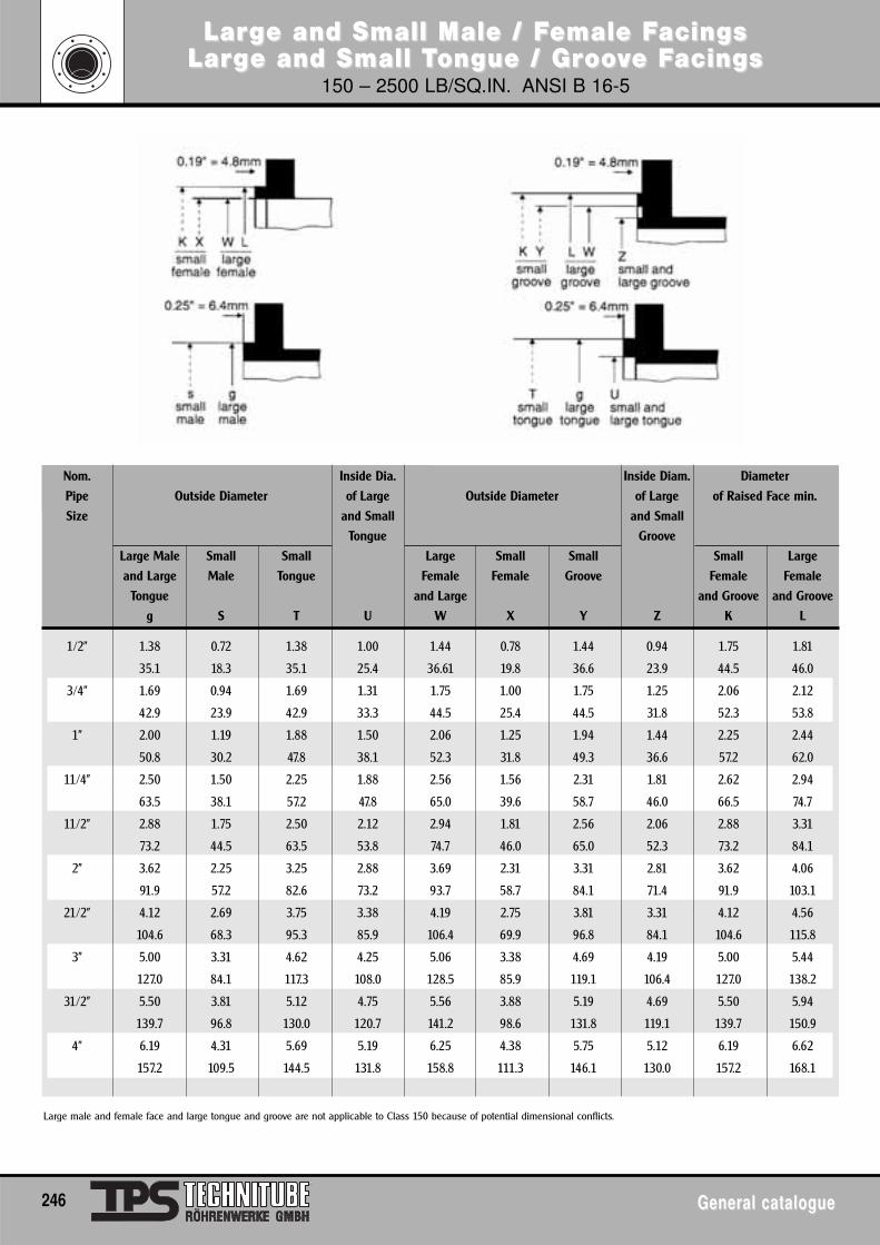
LarLargge and Small Male / Fe and Small Male / Female Female Facings acings LarLargge and Small Te and Small Tongue / Grongue / Groooovve Fe Facingsacings
150 – 2500 LB/SQ.IN. ANSI B 16-5
246 General catalogueGeneral catalogue
Nom. Inside Dia. Inside Diam. Diameter
Pipe Outside Diameter of Large Outside Diameter of Large of Raised Face min.
Size and Small and Small
Tongue Groove
Large Male Small Small Large Small Small Small Large
and Large Male Tongue Female Female Groove Female Female
Tongue and Large and Groove and Groove
g S T U W X Y Z K L
1/2” 1.38 0.72 1.38 1.00 1.44 0.78 1.44 0.94 1.75 1.81
35.1 18.3 35.1 25.4 36.61 19.8 36.6 23.9 44.5 46.0
3/4” 1.69 0.94 1.69 1.31 1.75 1.00 1.75 1.25 2.06 2.12
42.9 23.9 42.9 33.3 44.5 25.4 44.5 31.8 52.3 53.8
1” 2.00 1.19 1.88 1.50 2.06 1.25 1.94 1.44 2.25 2.44
50.8 30.2 47.8 38.1 52.3 31.8 49.3 36.6 57.2 62.0
11/4” 2.50 1.50 2.25 1.88 2.56 1.56 2.31 1.81 2.62 2.94
63.5 38.1 57.2 47.8 65.0 39.6 58.7 46.0 66.5 74.7
11/2” 2.88 1.75 2.50 2.12 2.94 1.81 2.56 2.06 2.88 3.31
73.2 44.5 63.5 53.8 74.7 46.0 65.0 52.3 73.2 84.1
2” 3.62 2.25 3.25 2.88 3.69 2.31 3.31 2.81 3.62 4.06
91.9 57.2 82.6 73.2 93.7 58.7 84.1 71.4 91.9 103.1
21/2” 4.12 2.69 3.75 3.38 4.19 2.75 3.81 3.31 4.12 4.56
104.6 68.3 95.3 85.9 106.4 69.9 96.8 84.1 104.6 115.8
3” 5.00 3.31 4.62 4.25 5.06 3.38 4.69 4.19 5.00 5.44
127.0 84.1 117.3 108.0 128.5 85.9 119.1 106.4 127.0 138.2
31/2” 5.50 3.81 5.12 4.75 5.56 3.88 5.19 4.69 5.50 5.94
139.7 96.8 130.0 120.7 141.2 98.6 131.8 119.1 139.7 150.9
4” 6.19 4.31 5.69 5.19 6.25 4.38 5.75 5.12 6.19 6.62
157.2 109.5 144.5 131.8 158.8 111.3 146.1 130.0 157.2 168.1
Large male and female face and large tongue and groove are not applicable to Class 150 because of potential dimensional conflicts.
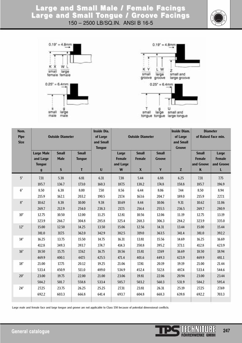
LarLargge and Small Male / Fe and Small Male / Female Female Facings acings LarLargge and Small Te and Small Tongue / Grongue / Groooovve Fe Facingsacings
150 – 2500 LB/SQ.IN. ANSI B 16-5
General catalogueGeneral catalogue 247
Nom. Inside Dia. Inside Diam. Diameter
Pipe Outside Diameter of Large Outside Diameter of Large of Raised Face min.
Size and Small and Small
Tongue Groove
Large Male Small Small Large Small Small Small Large
and Large Male Tongue Female Female Groove Female Female
Tongue and Large and Groove and Groove
g S T U W X Y Z K L
5” 7.31 5.38 6.81 6.31 7.38 5.44 6.88 6.25 7.31 7.75
185.7 136.7 173.0 160.3 187.5 138.2 174.8 158.8 185.7 196.9
6” 8.50 6.38 8.00 7.50 8.56 6.44 8.06 7.44 8.50 8.94
215.9 162.1 203.2 190.5 217.4 163.6 204.7 189.0 215.9 227.1
8” 10.62 8.38 10.00 9.38 10.69 8.44 10.06 9.31 10.62 11.06
269.7 212.9 254.0 238.3 217.5 214.4 255.5 236.5 269.7 280.9
10” 12.75 10.50 12.00 11.25 12.81 10.56 12.06 11.19 12.75 13.19
323.9 266.7 304.8 285.8 325.4 268.3 306.3 284.2 323.9 335.0
12” 15.00 12.50 14.25 13.50 15.06 12.56 14.31 13.44 15.00 15.44
381.0 317.5 362.0 342.9 382.5 319.0 363.5 341.4 381.0 392.2
14” 16.25 13.75 15.50 14.75 16.31 13.81 15.56 14.69 16.25 16.69
412.8 349.3 393.7 374.7 414.3 350.8 395.2 373.1 412.8 423.9
16” 18.50 15.75 17.62 16.75 18.56 15.81 17.69 16.69 18.50 18.94
469.9 400.1 447.5 425.5 471.4 401.6 449.3 423.9 469.9 481.1
18” 21.00 17.75 20.12 19.25 21.06 17.81 20.19 19.19 21.00 21.44
533.4 450.9 511.0 489.0 534.9 452.4 512.8 487.4 533.4 544.6
20” 23.00 19.75 22.00 21.00 23.06 19.81 22.06 20.94 23.00 23.44
584.2 501.7 558.8 533.4 585.7 503.2 560.3 531.9 584.2 595.4
24” 27.25 23.75 26.25 25.25 27.31 23.81 26.31 25.19 27.25 27.69
692.2 603.3 666.8 641.4 693.7 604.8 668.3 639.8 692.2 703.3
Large male and female face and large tongue and groove are not applicable to Class 150 because of potential dimensional conflicts.
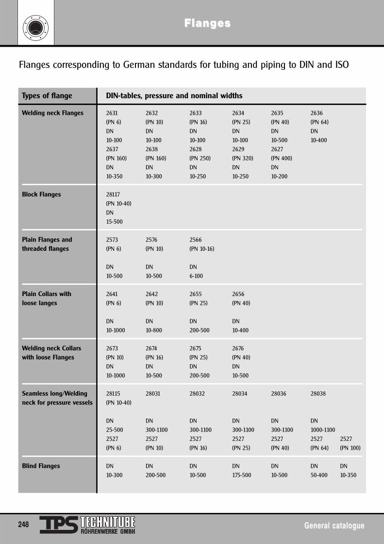
FlangFlangeses
248 General catalogueGeneral catalogue
Flanges corresponding to German standards for tubing and piping to DIN and ISO
Types of flange DIN-tables, pressure and nominal widths
Welding neck Flanges 2631 2632 2633 2634 2635 2636
(PN 6) (PN 10) (PN 16) (PN 25) (PN 40) (PN 64)
DN DN DN DN DN DN
10-100 10-100 10-100 10-100 10-500 10-400
2637 2638 2628 2629 2627
(PN 160) (PN 160) (PN 250) (PN 320) (PN 400)
DN DN DN DN DN
10-350 10-300 10-250 10-250 10-200
Block Flanges 28117
(PN 10-40)
DN
15-500
Plain Flanges and 2573 2576 2566
threaded flanges (PN 6) (PN 10) (PN 10-16)
DN DN DN
10-500 10-500 6-100
Plain Collars with 2641 2642 2655 2656
loose langes (PN 6) (PN 10) (PN 25) (PN 40)
DN DN DN DN
10-1000 10-800 200-500 10-400
Welding neck Collars 2673 2674 2675 2676
with loose Flanges (PN 10) (PN 16) (PN 25) (PN 40)
DN DN DN DN
10-1000 10-500 200-500 10-500
Seamless long/Welding 28115 28031 28032 28034 28036 28038
neck for pressure vessels (PN 10-40)
DN DN DN DN DN DN
25-500 300-1100 300-1100 300-1100 300-1100 1000-1100
2527 2527 2527 2527 2527 2527 2527
(PN 6) (PN 10) (PN 16) (PN 25) (PN 40) (PN 64) (PN 100)
Blind Flanges DN DN DN DN DN DN DN
10-300 200-500 10-500 175-500 10-500 50-400 10-350
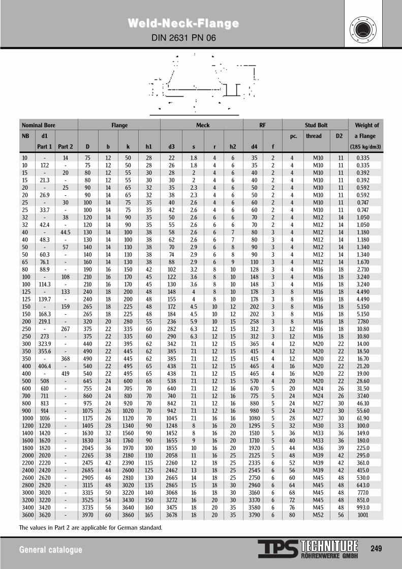
WWeld-Neld-Nececkk-Flang-Flange e DIN 2631 PN 06
General catalogueGeneral catalogue 249
Nominal Bore Flange Meck RF Stud Bolt Weight of
NB d1 pc. thread D2 a Flange
Part 1 Part 2 D b k h1 d3 s r h2 d4 f (7,85 kg/dm3)
10 - 14 75 12 50 28 22 1.8 4 6 35 2 4 M10 11 0.33510 17.2 - 75 12 50 28 26 1.8 4 6 35 2 4 M10 11 0.33515 - 20 80 12 55 30 28 2 4 6 40 2 4 M10 11 0.39215 21.3 - 80 12 55 30 30 2 4 6 40 2 4 M10 11 0.39220 - 25 90 14 65 32 35 2.3 4 6 50 2 4 M10 11 0.59220 26.9 - 90 14 65 32 38 2.3 4 6 50 2 4 M10 11 0.59225 - 30 100 14 75 35 40 2.6 4 6 60 2 4 M10 11 0.74725 33.7 - 100 14 75 35 42 2.6 4 6 60 2 4 M10 11 0.74732 - 38 120 14 90 35 50 2.6 6 6 70 2 4 M12 14 1.05032 42.4 - 120 14 90 35 55 2.6 6 6 70 2 4 M12 14 1.05040 - 44.5 130 14 100 38 58 2.6 6 7 80 3 4 M12 14 1.18040 48.3 - 130 14 100 38 62 2.6 6 7 80 3 4 M12 14 1.18050 - 57 140 14 110 38 70 2.9 6 8 90 3 4 M12 14 1.34050 60.3 - 140 14 110 38 74 2.9 6 8 90 3 4 M12 14 1.34065 76.1 - 160 14 130 38 88 2.9 6 9 110 3 4 M12 14 1.67080 88.9 - 190 16 150 42 102 3.2 8 10 128 3 4 M16 18 2.710100 - 108 210 16 170 45 122 3.6 8 10 148 3 4 M16 18 3.240100 114.3 - 210 16 170 45 130 3.6 8 10 148 3 4 M16 18 3.240125 - 133 240 18 200 48 148 4 8 10 178 3 8 M16 18 4.490125 139.7 - 240 18 200 48 155 4 8 10 178 3 8 M16 18 4.490150 - 159 265 18 225 48 172 4.5 10 12 202 3 8 M16 18 5.150150 168.3 - 265 18 225 48 184 4.5 10 12 202 3 8 M16 18 5.150200 219.1 - 320 20 280 55 236 5.9 10 15 258 3 8 M16 18 7.780250 - 267 375 22 335 60 282 6.3 12 15 312 3 12 M16 18 10.80250 273 - 375 22 335 60 290 6.3 12 15 312 3 12 M16 18 10.80300 323.9 - 440 22 395 62 342 7.1 12 15 365 4 12 M20 22 14.00350 355.6 - 490 22 445 62 385 7.1 12 15 415 4 12 M20 22 18.50350 - 368 490 22 445 62 385 7.1 12 15 415 4 12 M20 22 16.70400 406.4 - 540 22 495 65 438 7.1 12 15 465 4 16 M20 22 21.20400 - 419 540 22 495 65 438 7.1 12 15 465 4 16 M20 22 19.00500 508 - 645 24 600 68 538 7.1 12 15 570 4 20 M20 22 28.60600 610 - 755 24 705 70 640 7.1 12 16 670 5 20 M24 26 31.50700 711 - 860 24 810 70 740 7.1 12 16 775 5 24 M24 26 37.40800 813 - 975 24 920 70 842 7.1 12 16 880 5 24 M27 30 46.10900 914 - 1075 26 1020 70 942 7.1 12 16 980 5 24 M27 30 55.601000 1016 - 1175 26 1120 70 1045 7.1 16 16 1080 5 28 M27 30 61.901200 1220 - 1405 28 1340 90 1248 8 16 20 1295 5 32 M30 33 100.01400 1420 - 1630 32 1560 90 1452 8 16 20 1510 5 36 M33 36 149.01600 1620 - 1830 34 1760 90 1655 9 16 20 1710 5 40 M33 36 180.01800 1820 - 2045 36 1970 100 1855 10 16 20 1920 5 44 M36 39 225.02000 2020 - 2265 38 2180 110 2058 11 16 25 2125 5 48 M39 42 295.02200 2220 - 2475 42 2390 115 2260 12 18 25 2335 6 52 M39 42 361.02400 2420 - 2685 44 2600 125 2462 13 18 25 2545 6 56 M39 42 415.02600 2620 - 2905 46 2810 130 2665 14 18 25 2750 6 60 M45 48 530.02800 2820 - 3115 48 3020 135 2865 15 18 30 2960 6 64 M45 48 643.03000 3020 - 3315 50 3220 140 3068 16 18 30 3160 6 68 M45 48 777.03200 3220 - 3525 54 3430 150 3272 16 20 30 3370 6 72 M45 48 851.03400 3420 - 3735 56 3640 160 3475 18 20 35 3580 6 76 M45 48 993.03600 3620 - 3970 60 3860 165 3678 18 20 35 3790 6 80 M52 56 1001
The values in Part 2 are applicable for German standard.
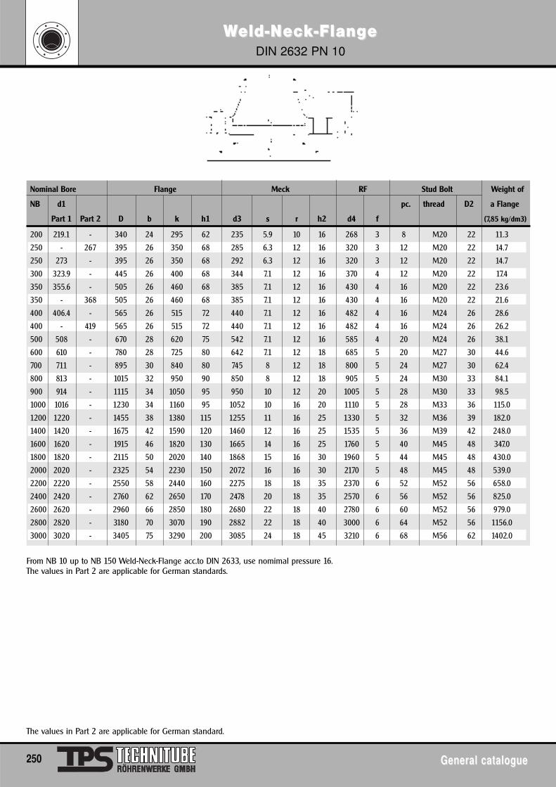
WWeld-Neld-Nececkk-Flang-Flange e DIN 2632 PN 10
250 General catalogueGeneral catalogue
Nominal Bore Flange Meck RF Stud Bolt Weight of
NB d1 pc. thread D2 a Flange
Part 1 Part 2 D b k h1 d3 s r h2 d4 f (7,85 kg/dm3)
200 219.1 - 340 24 295 62 235 5.9 10 16 268 3 8 M20 22 11.3
250 - 267 395 26 350 68 285 6.3 12 16 320 3 12 M20 22 14.7
250 273 - 395 26 350 68 292 6.3 12 16 320 3 12 M20 22 14.7
300 323.9 - 445 26 400 68 344 7.1 12 16 370 4 12 M20 22 17.4
350 355.6 - 505 26 460 68 385 7.1 12 16 430 4 16 M20 22 23.6
350 - 368 505 26 460 68 385 7.1 12 16 430 4 16 M20 22 21.6
400 406.4 - 565 26 515 72 440 7.1 12 16 482 4 16 M24 26 28.6
400 - 419 565 26 515 72 440 7.1 12 16 482 4 16 M24 26 26.2
500 508 - 670 28 620 75 542 7.1 12 16 585 4 20 M24 26 38.1
600 610 - 780 28 725 80 642 7.1 12 18 685 5 20 M27 30 44.6
700 711 - 895 30 840 80 745 8 12 18 800 5 24 M27 30 62.4
800 813 - 1015 32 950 90 850 8 12 18 905 5 24 M30 33 84.1
900 914 - 1115 34 1050 95 950 10 12 20 1005 5 28 M30 33 98.5
1000 1016 - 1230 34 1160 95 1052 10 16 20 1110 5 28 M33 36 115.0
1200 1220 - 1455 38 1380 115 1255 11 16 25 1330 5 32 M36 39 182.0
1400 1420 - 1675 42 1590 120 1460 12 16 25 1535 5 36 M39 42 248.0
1600 1620 - 1915 46 1820 130 1665 14 16 25 1760 5 40 M45 48 347.0
1800 1820 - 2115 50 2020 140 1868 15 16 30 1960 5 44 M45 48 430.0
2000 2020 - 2325 54 2230 150 2072 16 16 30 2170 5 48 M45 48 539.0
2200 2220 - 2550 58 2440 160 2275 18 18 35 2370 6 52 M52 56 658.0
2400 2420 - 2760 62 2650 170 2478 20 18 35 2570 6 56 M52 56 825.0
2600 2620 - 2960 66 2850 180 2680 22 18 40 2780 6 60 M52 56 979.0
2800 2820 - 3180 70 3070 190 2882 22 18 40 3000 6 64 M52 56 1156.0
3000 3020 - 3405 75 3290 200 3085 24 18 45 3210 6 68 M56 62 1402.0
The values in Part 2 are applicable for German standard.
From NB 10 up to NB 150 Weld-Neck-Flange acc.to DIN 2633, use nomimal pressure 16.The values in Part 2 are applicable for German standards.
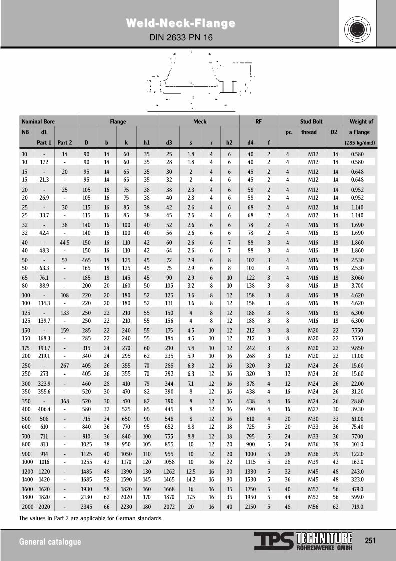
WWeld-Neld-Nececkk-Flang-Flange e DIN 2633 PN 16
General catalogueGeneral catalogue 251
Nominal Bore Flange Meck RF Stud Bolt Weight of
NB d1 pc. thread D2 a Flange
Part 1 Part 2 D b k h1 d3 s r h2 d4 f (7,85 kg/dm3)
10 - 14 90 14 60 35 25 1.8 4 6 40 2 4 M12 14 0.58010 17.2 - 90 14 60 35 28 1.8 4 6 40 2 4 M12 14 0.580
15 - 20 95 14 65 35 30 2 4 6 45 2 4 M12 14 0.64815 21.3 - 95 14 65 35 32 2 4 6 45 2 4 M12 14 0.648
20 - 25 105 16 75 38 38 2.3 4 6 58 2 4 M12 14 0.95220 26.9 - 105 16 75 38 40 2.3 4 6 58 2 4 M12 14 0.952
25 - 30 115 16 85 38 42 2.6 4 6 68 2 4 M12 14 1.14025 33.7 - 115 16 85 38 45 2.6 4 6 68 2 4 M12 14 1.140
32 - 38 140 16 100 40 52 2.6 6 6 78 2 4 M16 18 1.69032 42.4 - 140 16 100 40 56 2.6 6 6 78 2 4 M16 18 1.690
40 - 44.5 150 16 110 42 60 2.6 6 7 88 3 4 M16 18 1.86040 48.3 - 150 16 110 42 64 2.6 6 7 88 3 4 M16 18 1.860
50 - 57 465 18 125 45 72 2.9 6 8 102 3 4 M16 18 2.53050 63.3 - 165 18 125 45 75 2.9 6 8 102 3 4 M16 18 2.530
65 76.1 - 185 18 145 45 90 2.9 6 10 122 3 4 M16 18 3.06080 88.9 - 200 20 160 50 105 3.2 8 10 138 3 8 M16 18 3.700
100 - 108 220 20 180 52 125 3.6 8 12 158 3 8 M16 18 4.620100 114.3 - 220 20 180 52 131 3.6 8 12 158 3 8 M16 18 4.620
125 - 133 250 22 210 55 150 4 8 12 188 3 8 M16 18 6.300125 139.7 - 250 22 210 55 156 4 8 12 188 3 8 M16 18 6.300
150 - 159 285 22 240 55 175 4.5 10 12 212 3 8 M20 22 7.750150 168.3 - 285 22 240 55 184 4.5 10 12 212 3 8 M20 22 7.750
175 193.7 - 315 24 270 60 210 5.4 10 12 242 3 8 M20 22 9.850200 219.1 - 340 24 295 62 235 5.9 10 16 268 3 12 M20 22 11.00
250 - 267 405 26 355 70 285 6.3 12 16 320 3 12 M24 26 15.60250 273 - 405 26 355 70 292 6.3 12 16 320 3 12 M24 26 15.60
300 323.9 - 460 28 410 78 344 7.1 12 16 378 4 12 M24 26 22.00350 355.6 - 520 30 470 82 390 8 12 16 438 4 16 M24 26 31.20
350 - 368 520 30 470 82 390 8 12 16 438 4 16 M24 26 28.80400 406.4 - 580 32 525 85 445 8 12 16 490 4 16 M27 30 39.30
500 508 - 715 34 650 90 548 8 12 16 610 4 20 M30 33 61.00600 610 - 840 36 770 95 652 8.8 12 18 725 5 20 M33 36 75.40
700 711 - 910 36 840 100 755 8.8 12 18 795 5 24 M33 36 77.00800 813 - 1025 38 950 105 855 10 12 20 900 5 24 M36 39 101.0
900 914 - 1125 40 1050 110 955 10 12 20 1000 5 28 M36 39 122.01000 1016 - 1255 42 1170 120 1058 10 16 22 1115 5 28 M39 42 162.0
1200 1220 - 1485 48 1390 130 1262 12.5 16 30 1330 5 32 M45 48 243.01400 1420 - 1685 52 1590 145 1465 14.2 16 30 1530 5 36 M45 48 323.0
1600 1620 - 1930 58 1820 160 1668 16 16 35 1750 5 40 M52 56 479.01800 1820 - 2130 62 2020 170 1870 17.5 16 35 1950 5 44 M52 56 599.0
2000 2020 - 2345 66 2230 180 2072 20 16 40 2150 5 48 M56 62 719.0
The values in Part 2 are applicable for German standards.
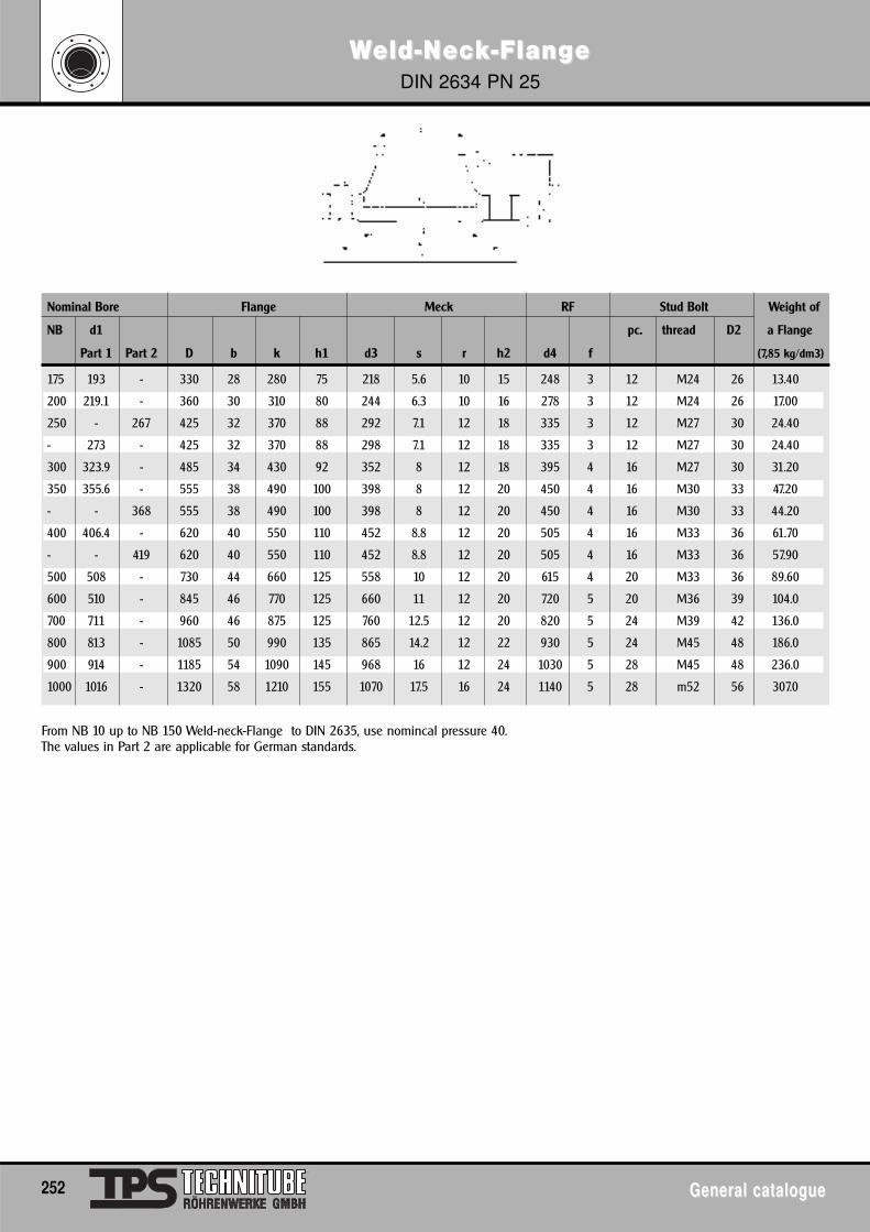
WWeld-Neld-Nececkk-Flang-Flange e DIN 2634 PN 25
252 General catalogueGeneral catalogue
Nominal Bore Flange Meck RF Stud Bolt Weight of
NB d1 pc. thread D2 a Flange
Part 1 Part 2 D b k h1 d3 s r h2 d4 f (7,85 kg/dm3)
175 193 - 330 28 280 75 218 5.6 10 15 248 3 12 M24 26 13.40
200 219.1 - 360 30 310 80 244 6.3 10 16 278 3 12 M24 26 17.00
250 - 267 425 32 370 88 292 7.1 12 18 335 3 12 M27 30 24.40
- 273 - 425 32 370 88 298 7.1 12 18 335 3 12 M27 30 24.40
300 323.9 - 485 34 430 92 352 8 12 18 395 4 16 M27 30 31.20
350 355.6 - 555 38 490 100 398 8 12 20 450 4 16 M30 33 47.20
- - 368 555 38 490 100 398 8 12 20 450 4 16 M30 33 44.20
400 406.4 - 620 40 550 110 452 8.8 12 20 505 4 16 M33 36 61.70
- - 419 620 40 550 110 452 8.8 12 20 505 4 16 M33 36 57.90
500 508 - 730 44 660 125 558 10 12 20 615 4 20 M33 36 89.60
600 510 - 845 46 770 125 660 11 12 20 720 5 20 M36 39 104.0
700 711 - 960 46 875 125 760 12.5 12 20 820 5 24 M39 42 136.0
800 813 - 1085 50 990 135 865 14.2 12 22 930 5 24 M45 48 186.0
900 914 - 1185 54 1090 145 968 16 12 24 1030 5 28 M45 48 236.0
1000 1016 - 1320 58 1210 155 1070 17.5 16 24 1140 5 28 m52 56 307.0
From NB 10 up to NB 150 Weld-neck-Flange to DIN 2635, use nomincal pressure 40. The values in Part 2 are applicable for German standards.
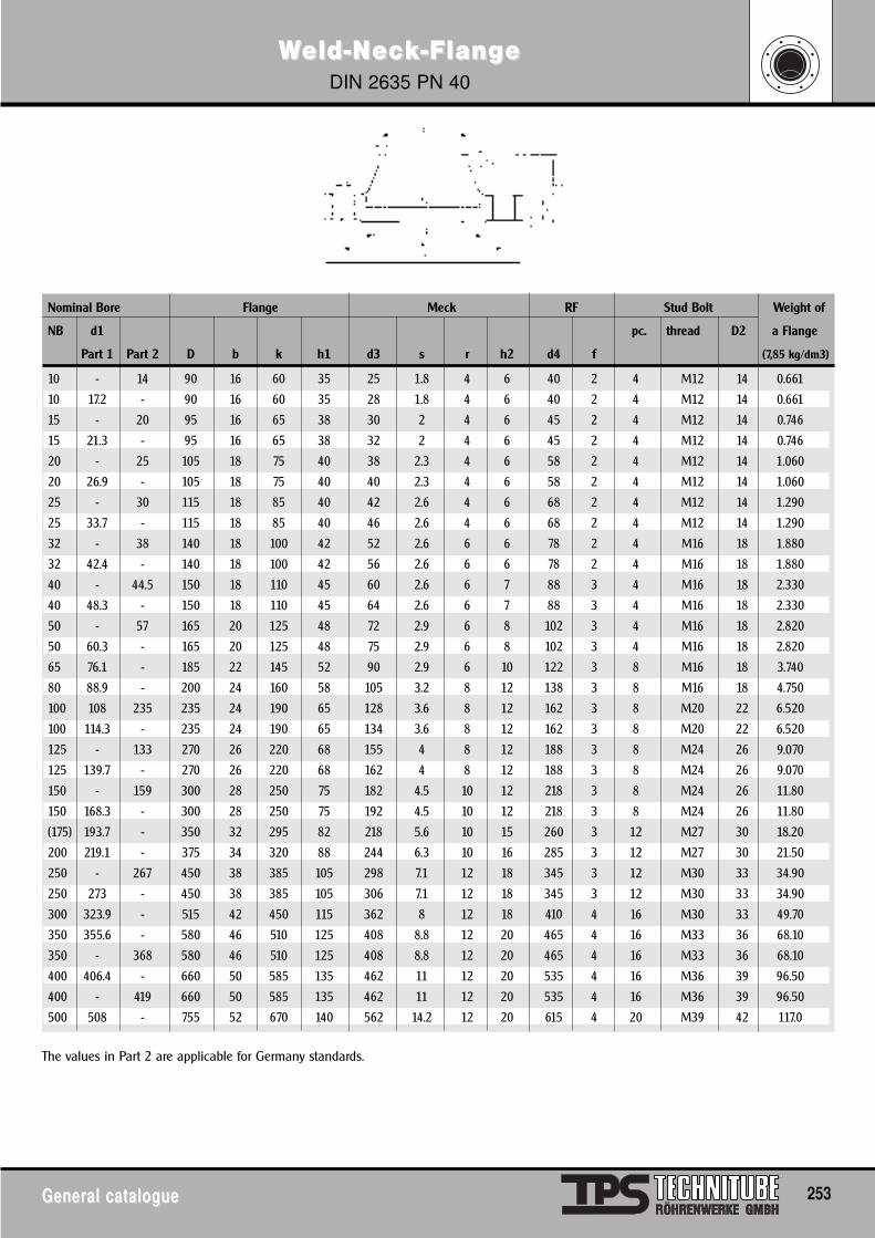
WWeld-Neld-Nececkk-Flang-Flange e DIN 2635 PN 40
General catalogueGeneral catalogue 253
Nominal Bore Flange Meck RF Stud Bolt Weight of
NB d1 pc. thread D2 a Flange
Part 1 Part 2 D b k h1 d3 s r h2 d4 f (7,85 kg/dm3)
10 - 14 90 16 60 35 25 1.8 4 6 40 2 4 M12 14 0.661
10 17.2 - 90 16 60 35 28 1.8 4 6 40 2 4 M12 14 0.661
15 - 20 95 16 65 38 30 2 4 6 45 2 4 M12 14 0.746
15 21.3 - 95 16 65 38 32 2 4 6 45 2 4 M12 14 0.746
20 - 25 105 18 75 40 38 2.3 4 6 58 2 4 M12 14 1.060
20 26.9 - 105 18 75 40 40 2.3 4 6 58 2 4 M12 14 1.060
25 - 30 115 18 85 40 42 2.6 4 6 68 2 4 M12 14 1.290
25 33.7 - 115 18 85 40 46 2.6 4 6 68 2 4 M12 14 1.290
32 - 38 140 18 100 42 52 2.6 6 6 78 2 4 M16 18 1.880
32 42.4 - 140 18 100 42 56 2.6 6 6 78 2 4 M16 18 1.880
40 - 44.5 150 18 110 45 60 2.6 6 7 88 3 4 M16 18 2.330
40 48.3 - 150 18 110 45 64 2.6 6 7 88 3 4 M16 18 2.330
50 - 57 165 20 125 48 72 2.9 6 8 102 3 4 M16 18 2.820
50 60.3 - 165 20 125 48 75 2.9 6 8 102 3 4 M16 18 2.820
65 76.1 - 185 22 145 52 90 2.9 6 10 122 3 8 M16 18 3.740
80 88.9 - 200 24 160 58 105 3.2 8 12 138 3 8 M16 18 4.750
100 108 235 235 24 190 65 128 3.6 8 12 162 3 8 M20 22 6.520
100 114.3 - 235 24 190 65 134 3.6 8 12 162 3 8 M20 22 6.520
125 - 133 270 26 220 68 155 4 8 12 188 3 8 M24 26 9.070
125 139.7 - 270 26 220 68 162 4 8 12 188 3 8 M24 26 9.070
150 - 159 300 28 250 75 182 4.5 10 12 218 3 8 M24 26 11.80
150 168.3 - 300 28 250 75 192 4.5 10 12 218 3 8 M24 26 11.80
(175) 193.7 - 350 32 295 82 218 5.6 10 15 260 3 12 M27 30 18.20
200 219.1 - 375 34 320 88 244 6.3 10 16 285 3 12 M27 30 21.50
250 - 267 450 38 385 105 298 7.1 12 18 345 3 12 M30 33 34.90
250 273 - 450 38 385 105 306 7.1 12 18 345 3 12 M30 33 34.90
300 323.9 - 515 42 450 115 362 8 12 18 410 4 16 M30 33 49.70
350 355.6 - 580 46 510 125 408 8.8 12 20 465 4 16 M33 36 68.10
350 - 368 580 46 510 125 408 8.8 12 20 465 4 16 M33 36 68.10
400 406.4 - 660 50 585 135 462 11 12 20 535 4 16 M36 39 96.50
400 - 419 660 50 585 135 462 11 12 20 535 4 16 M36 39 96.50
500 508 - 755 52 670 140 562 14.2 12 20 615 4 20 M39 42 117.0
The values in Part 2 are applicable for Germany standards.
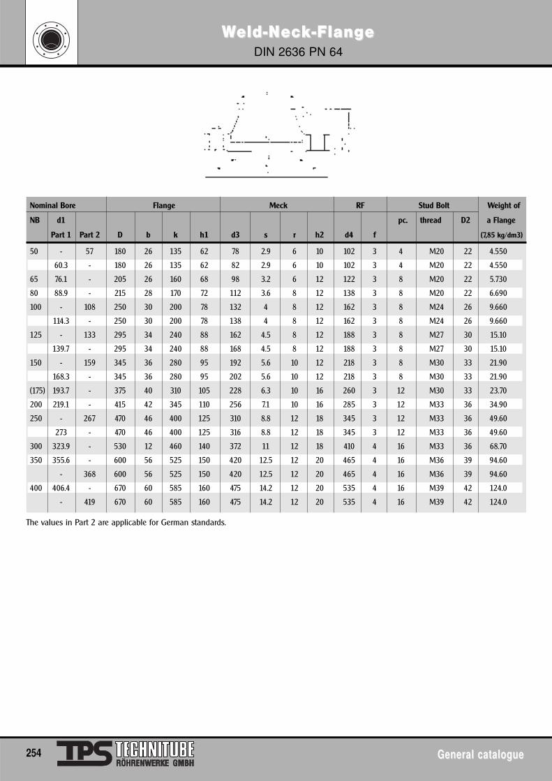
WWeld-Neld-Nececkk-Flang-Flange e DIN 2636 PN 64
254 General catalogueGeneral catalogue
Nominal Bore Flange Meck RF Stud Bolt Weight of
NB d1 pc. thread D2 a Flange
Part 1 Part 2 D b k h1 d3 s r h2 d4 f (7,85 kg/dm3)
50 - 57 180 26 135 62 78 2.9 6 10 102 3 4 M20 22 4.550
60.3 - 180 26 135 62 82 2.9 6 10 102 3 4 M20 22 4.550
65 76.1 - 205 26 160 68 98 3.2 6 12 122 3 8 M20 22 5.730
80 88.9 - 215 28 170 72 112 3.6 8 12 138 3 8 M20 22 6.690
100 - 108 250 30 200 78 132 4 8 12 162 3 8 M24 26 9.660
114.3 - 250 30 200 78 138 4 8 12 162 3 8 M24 26 9.660
125 - 133 295 34 240 88 162 4.5 8 12 188 3 8 M27 30 15.10
139.7 - 295 34 240 88 168 4.5 8 12 188 3 8 M27 30 15.10
150 - 159 345 36 280 95 192 5.6 10 12 218 3 8 M30 33 21.90
168.3 - 345 36 280 95 202 5.6 10 12 218 3 8 M30 33 21.90
(175) 193.7 - 375 40 310 105 228 6.3 10 16 260 3 12 M30 33 23.70
200 219.1 - 415 42 345 110 256 7.1 10 16 285 3 12 M33 36 34.90
250 - 267 470 46 400 125 310 8.8 12 18 345 3 12 M33 36 49.60
273 - 470 46 400 125 316 8.8 12 18 345 3 12 M33 36 49.60
300 323.9 - 530 12 460 140 372 11 12 18 410 4 16 M33 36 68.70
350 355.6 - 600 56 525 150 420 12.5 12 20 465 4 16 M36 39 94.60
- 368 600 56 525 150 420 12.5 12 20 465 4 16 M36 39 94.60
400 406.4 - 670 60 585 160 475 14.2 12 20 535 4 16 M39 42 124.0
- 419 670 60 585 160 475 14.2 12 20 535 4 16 M39 42 124.0
The values in Part 2 are applicable for German standards.
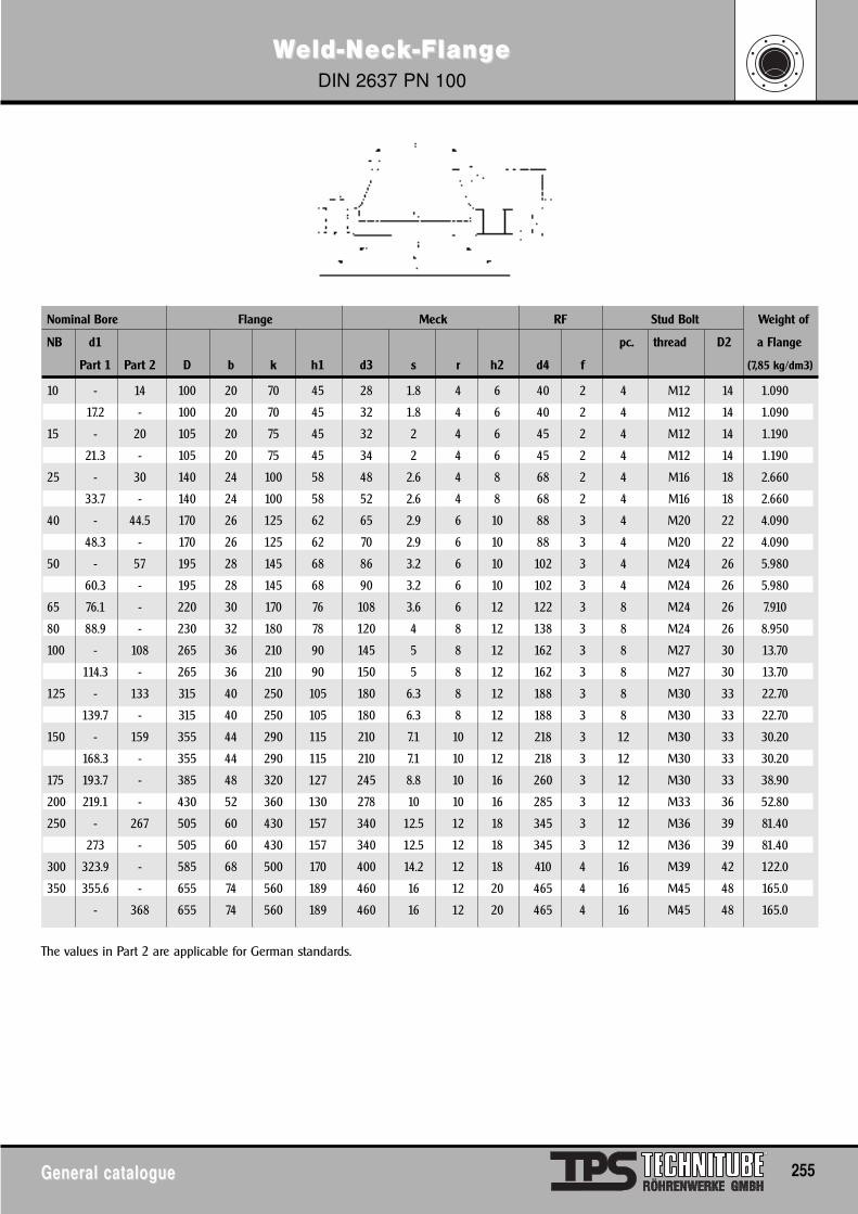
WWeld-Neld-Nececkk-Flang-Flange e DIN 2637 PN 100
General catalogueGeneral catalogue 255
Nominal Bore Flange Meck RF Stud Bolt Weight of
NB d1 pc. thread D2 a Flange
Part 1 Part 2 D b k h1 d3 s r h2 d4 f (7,85 kg/dm3)
10 - 14 100 20 70 45 28 1.8 4 6 40 2 4 M12 14 1.090
17.2 - 100 20 70 45 32 1.8 4 6 40 2 4 M12 14 1.090
15 - 20 105 20 75 45 32 2 4 6 45 2 4 M12 14 1.190
21.3 - 105 20 75 45 34 2 4 6 45 2 4 M12 14 1.190
25 - 30 140 24 100 58 48 2.6 4 8 68 2 4 M16 18 2.660
33.7 - 140 24 100 58 52 2.6 4 8 68 2 4 M16 18 2.660
40 - 44.5 170 26 125 62 65 2.9 6 10 88 3 4 M20 22 4.090
48.3 - 170 26 125 62 70 2.9 6 10 88 3 4 M20 22 4.090
50 - 57 195 28 145 68 86 3.2 6 10 102 3 4 M24 26 5.980
60.3 - 195 28 145 68 90 3.2 6 10 102 3 4 M24 26 5.980
65 76.1 - 220 30 170 76 108 3.6 6 12 122 3 8 M24 26 7.910
80 88.9 - 230 32 180 78 120 4 8 12 138 3 8 M24 26 8.950
100 - 108 265 36 210 90 145 5 8 12 162 3 8 M27 30 13.70
114.3 - 265 36 210 90 150 5 8 12 162 3 8 M27 30 13.70
125 - 133 315 40 250 105 180 6.3 8 12 188 3 8 M30 33 22.70
139.7 - 315 40 250 105 180 6.3 8 12 188 3 8 M30 33 22.70
150 - 159 355 44 290 115 210 7.1 10 12 218 3 12 M30 33 30.20
168.3 - 355 44 290 115 210 7.1 10 12 218 3 12 M30 33 30.20
175 193.7 - 385 48 320 127 245 8.8 10 16 260 3 12 M30 33 38.90
200 219.1 - 430 52 360 130 278 10 10 16 285 3 12 M33 36 52.80
250 - 267 505 60 430 157 340 12.5 12 18 345 3 12 M36 39 81.40
273 - 505 60 430 157 340 12.5 12 18 345 3 12 M36 39 81.40
300 323.9 - 585 68 500 170 400 14.2 12 18 410 4 16 M39 42 122.0
350 355.6 - 655 74 560 189 460 16 12 20 465 4 16 M45 48 165.0
- 368 655 74 560 189 460 16 12 20 465 4 16 M45 48 165.0
The values in Part 2 are applicable for German standards.
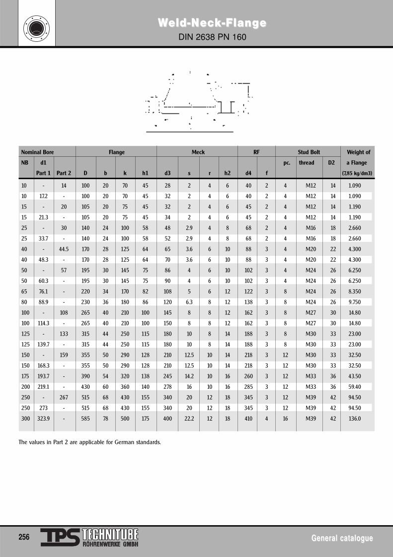
WWeld-Neld-Nececkk-Flang-Flange e DIN 2638 PN 160
256 General catalogueGeneral catalogue
Nominal Bore Flange Meck RF Stud Bolt Weight of
NB d1 pc. thread D2 a Flange
Part 1 Part 2 D b k h1 d3 s r h2 d4 f (7,85 kg/dm3)
10 - 14 100 20 70 45 28 2 4 6 40 2 4 M12 14 1.090
10 17.2 - 100 20 70 45 32 2 4 6 40 2 4 M12 14 1.090
15 - 20 105 20 75 45 32 2 4 6 45 2 4 M12 14 1.190
15 21.3 - 105 20 75 45 34 2 4 6 45 2 4 M12 14 1.190
25 - 30 140 24 100 58 48 2.9 4 8 68 2 4 M16 18 2.660
25 33.7 - 140 24 100 58 52 2.9 4 8 68 2 4 M16 18 2.660
40 - 44.5 170 28 125 64 65 3.6 6 10 88 3 4 M20 22 4.300
40 48.3 - 170 28 125 64 70 3.6 6 10 88 3 4 M20 22 4.300
50 - 57 195 30 145 75 86 4 6 10 102 3 4 M24 26 6.250
50 60.3 - 195 30 145 75 90 4 6 10 102 3 4 M24 26 6.250
65 76.1 - 220 34 170 82 108 5 6 12 122 3 8 M24 26 8.350
80 88.9 - 230 36 180 86 120 6.3 8 12 138 3 8 M24 26 9.750
100 - 108 265 40 210 100 145 8 8 12 162 3 8 M27 30 14.80
100 114.3 - 265 40 210 100 150 8 8 12 162 3 8 M27 30 14.80
125 - 133 315 44 250 115 180 10 8 14 188 3 8 M30 33 23.00
125 139.7 - 315 44 250 115 180 10 8 14 188 3 8 M30 33 23.00
150 - 159 355 50 290 128 210 12.5 10 14 218 3 12 M30 33 32.50
150 168.3 - 355 50 290 128 210 12.5 10 14 218 3 12 M30 33 32.50
175 193.7 - 390 54 320 138 245 14.2 10 16 260 3 12 M33 36 43.50
200 219.1 - 430 60 360 140 278 16 10 16 285 3 12 M33 36 59.40
250 - 267 515 68 430 155 340 20 12 18 345 3 12 M39 42 94.50
250 273 - 515 68 430 155 340 20 12 18 345 3 12 M39 42 94.50
300 323.9 - 585 78 500 175 400 22.2 12 18 410 4 16 M39 42 136.0
The values in Part 2 are applicable for German standards.
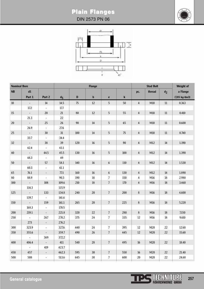
Plain FlangPlain Flanges es DIN 2573 PN 06
General catalogueGeneral catalogue 257
Nominal Bore Flange Stud Bolt Weight of
NB d1 pc. thread d2 a Flange
Part 1 Part 2 d5 D b e k (7,85 kg/dm3)
10 - 14 14.5 75 12 5 50 4 M10 11 0.363
17.2 - 17.7
15 - 20 21 80 12 5 55 4 M10 11 0.410
21.3 - 22
20 - 25 26 90 14 5 65 4 M10 11 0.600
26.9 - 27.6
25 - 30 31 100 14 5 75 4 M10 11 0.740
33.7 - 34.4
32 - 38 39 120 16 5 90 4 M12 14 1.190
42.4 - 43.1
40 - 44.5 45.5 130 16 5 100 4 M12 14 1.390
48.3 - 49
50 - 57 58.1 140 16 6 110 4 M12 14 1.530
60.3 - 61.1
65 76.1 - 77.1 160 16 6 130 4 M12 14 1.890
80 88.9 - 90.3 190 18 7 150 4 M16 18 2.980
100 - 108 109.6 210 18 7 170 4 M16 18 3.460
114.3 115.9
125 - 133 134.8 240 20 7 200 8 M16 18 4.600
139.7 - 141.6
150 - 159 161.1 265 20 7 225 8 M16 18 5.220
168.3 - 170.5
200 219.1 - 221.8 320 22 7 280 8 M16 18 7.150
250 - 267 270.2 375 24 7 335 12 M16 18 9.610
273 - 276.2
300 323.9 - 327.6 440 24 7 395 12 M20 22 12.60
350 355.6 - 359.7 490 26 7 445 12 M20 22 15.60
- 369 372.2
400 406.4 - 411 540 28 7 495 16 M20 22 18.40
- 419 423.7
450 457 - 462.3 595 30 7 550 16 M20 22 21.40
500 508 - 513.6 645 30 7 600 20 M20 22 24.60
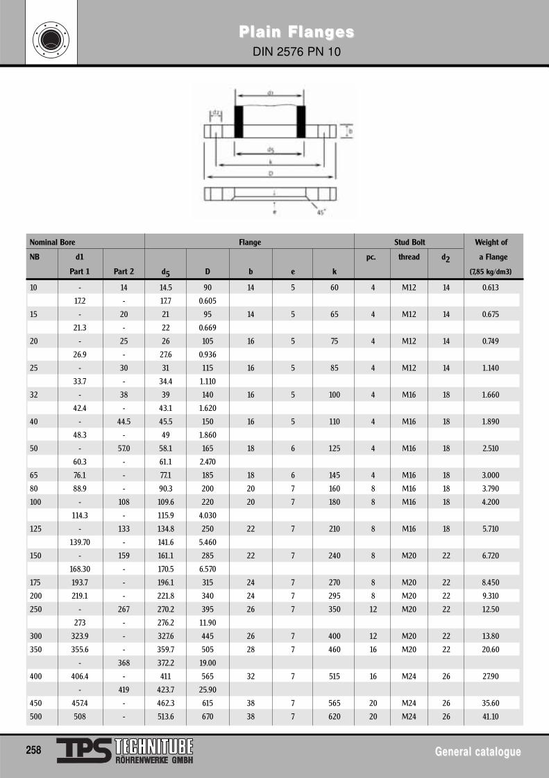
Plain FlangPlain Flanges es DIN 2576 PN 10
258 General catalogueGeneral catalogue
Nominal Bore Flange Stud Bolt Weight of
NB d1 pc. thread d2 a Flange
Part 1 Part 2 d5 D b e k (7,85 kg/dm3)
10 - 14 14.5 90 14 5 60 4 M12 14 0.613
17.2 - 17.7 0.605
15 - 20 21 95 14 5 65 4 M12 14 0.675
21.3 - 22 0.669
20 - 25 26 105 16 5 75 4 M12 14 0.749
26.9 - 27.6 0.936
25 - 30 31 115 16 5 85 4 M12 14 1.140
33.7 - 34.4 1.110
32 - 38 39 140 16 5 100 4 M16 18 1.660
42.4 - 43.1 1.620
40 - 44.5 45.5 150 16 5 110 4 M16 18 1.890
48.3 - 49 1.860
50 - 57.0 58.1 165 18 6 125 4 M16 18 2.510
60.3 - 61.1 2.470
65 76.1 - 77.1 185 18 6 145 4 M16 18 3.000
80 88.9 - 90.3 200 20 7 160 8 M16 18 3.790
100 - 108 109.6 220 20 7 180 8 M16 18 4.200
114.3 - 115.9 4.030
125 - 133 134.8 250 22 7 210 8 M16 18 5.710
139.70 - 141.6 5.460
150 - 159 161.1 285 22 7 240 8 M20 22 6.720
168.30 - 170.5 6.570
175 193.7 - 196.1 315 24 7 270 8 M20 22 8.450
200 219.1 - 221.8 340 24 7 295 8 M20 22 9.310
250 - 267 270.2 395 26 7 350 12 M20 22 12.50
273 - 276.2 11.90
300 323.9 - 327.6 445 26 7 400 12 M20 22 13.80
350 355.6 - 359.7 505 28 7 460 16 M20 22 20.60
- 368 372.2 19.00
400 406.4 - 411 565 32 7 515 16 M24 26 27.90
- 419 423.7 25.90
450 457.4 - 462.3 615 38 7 565 20 M24 26 35.60
500 508 - 513.6 670 38 7 620 20 M24 26 41.10
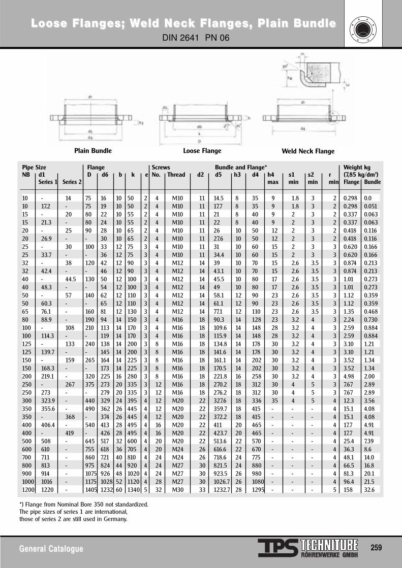
Loose FlangLoose Flanges; Wes; Weld Neld Nececk Flangk Flanges, Plain Bundlees, Plain BundleDIN 2641 PN 06
General CatalogueGeneral Catalogue 259
Pipe Size Flange Screws Bundle and Flange* Weight kgNB d1 D d6 b k e No. Thread d2 d5 h3 d4 h4 s1 s2 r (7,85 kg/dm3)
Series 1 Series 2 max min min min Flange Bundle
10 - 14 75 16 10 50 2 4 M10 11 14.5 8 35 9 1.8 3 2 0.298 0.010 17.2 - 75 19 10 50 2 4 M10 11 17.7 8 35 9 1.8 3 2 0.298 0.05115 - 20 80 22 10 55 2 4 M10 11 21 8 40 9 2 3 2 0.337 0.06315 21.3 - 80 24 10 55 2 4 M10 11 22 8 40 9 2 3 2 0.337 0.06320 - 25 90 28 10 65 2 4 M10 11 26 10 50 12 2 3 2 0.418 0.11620 26.9 - - 30 10 65 2 4 M10 11 27.6 10 50 12 2 3 2 0.418 0.11625 - 30 100 33 12 75 3 4 M10 11 31 10 60 15 2 3 3 0.620 0.16625 33.7 - - 36 12 75 3 4 M10 11 34.4 10 60 15 2 3 3 0.620 0.16632 - 38 120 42 12 90 3 4 M12 14 39 10 70 15 2.6 3.5 3 0.874 0.21332 42.4 - - 46 12 90 3 4 M12 14 43.1 10 70 15 2.6 3.5 3 0.874 0.21340 - 44.5 130 50 12 100 3 4 M12 14 45.5 10 80 17 2.6 3.5 3 1.01 0.27340 48.3 - - 54 12 100 3 4 M12 14 49 10 80 17 2.6 3.5 3 1.01 0.27350 - 57 140 62 12 110 3 4 M12 14 58.1 12 90 23 2.6 3.5 3 1.12 0.35950 60.3 - - 65 12 110 3 4 M12 14 61.1 12 90 23 2.6 3.5 3 1.12 0.35965 76.1 - 160 81 12 130 3 4 M12 14 77.1 12 110 23 2.6 3.5 3 1.35 0.46880 88.9 - 190 94 14 150 3 4 M16 18 90.3 14 128 23 3.2 4 3 2.24 0.730100 - 108 210 113 14 170 3 4 M16 18 109.6 14 148 28 3.2 4 3 2.59 0.884100 114.3 - - 119 14 170 3 4 M16 18 115.9 14 148 28 3.2 4 3 2.59 0.884125 - 133 240 138 14 200 3 8 M16 18 134.8 14 178 30 3.2 4 3 3.10 1.21125 139.7 - - 145 14 200 3 8 M16 18 141.6 14 178 30 3.2 4 3 3.10 1.21150 - 159 265 164 14 225 3 8 M16 18 161.1 14 202 30 3.2 4 3 3.52 1.34150 168.3 - - 173 14 225 3 8 M16 18 170.5 14 202 30 3.2 4 3 3.52 1.34200 219.1 - 320 225 16 280 3 8 M16 18 221.8 16 258 30 3.2 4 3 4.98 2.00250 - 267 375 273 20 335 3 12 M16 18 270.2 18 312 30 4 5 3 7.67 2.89250 273 - - 279 20 335 3 12 M16 18 276.2 18 312 30 4 5 3 7.67 2.89300 323.9 - 440 329 24 395 4 12 M20 22 327.6 18 336 35 4 5 4 12.3 3.56350 355.6 - 490 362 26 445 4 12 M20 22 359.7 18 415 - - - 4 15.1 4.08350 - 368 - 374 26 445 4 12 M20 22 372.2 18 415 - - - 4 15.1 4.08400 406.4 - 540 413 28 495 4 16 M20 22 411 20 465 - - - 4 17.7 4.91400 - 419 - 426 28 495 4 16 M20 22 423.7 20 465 - - - 4 17.7 4.91500 508 - 645 517 32 600 4 20 M20 22 513.6 22 570 - - - 4 25.4 7.39600 610 - 755 618 36 705 4 20 M24 26 616.6 22 670 - - - 4 36.3 8.6700 711 - 860 721 40 810 4 24 M24 26 718.6 24 775 - - - 4 48.1 14.0800 813 - 975 824 44 920 4 24 M27 30 821.5 24 880 - - - 4 66.5 16.8 900 914 - 1075 926 48 1020 4 24 M27 30 923.5 26 980 - - - 4 81.3 20.11000 1016 - 1175 1028 52 1120 4 28 M27 30 1026.7 26 1080 - - - 4 96.4 21.51200 1220 - 1405 1232 60 1340 5 32 M30 33 1232.7 28 1295 - - - 5 158 32.6
Plain Bundle Loose Flange Weld Neck Flange
*) Flange from Nominal Bore 350 not standardized.The pipe sizes of series 1 are international,those of series 2 are still used in Germany.
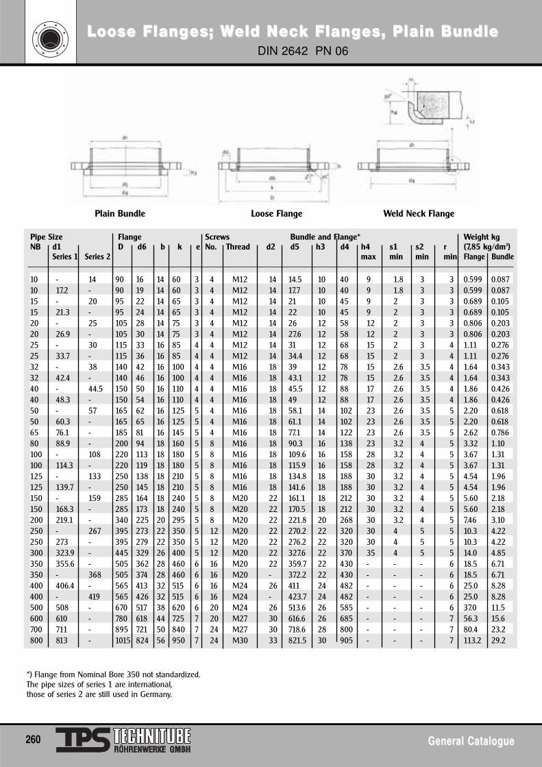
Loose FlangLoose Flanges; Wes; Weld Neld Nececk Flangk Flanges, Plain Bundlees, Plain BundleDIN 2642 PN 06
260 General CatalogueGeneral Catalogue
Pipe Size Flange Screws Bundle and Flange* Weight kgNB d1 D d6 b k e No. Thread d2 d5 h3 d4 h4 s1 s2 r (7,85 kg/dm3)
Series 1 Series 2 max min min min Flange Bundle
10 - 14 90 16 14 60 3 4 M12 14 14.5 10 40 9 1.8 3 3 0.599 0.08710 17.2 - 90 19 14 60 3 4 M12 14 17.7 10 40 9 1.8 3 3 0.599 0.08715 - 20 95 22 14 65 3 4 M12 14 21 10 45 9 2 3 3 0.689 0.10515 21.3 - 95 24 14 65 3 4 M12 14 22 10 45 9 2 3 3 0.689 0.10520 - 25 105 28 14 75 3 4 M12 14 26 12 58 12 2 3 3 0.806 0.20320 26.9 - 105 30 14 75 3 4 M12 14 27.6 12 58 12 2 3 3 0.806 0.20325 - 30 115 33 16 85 4 4 M12 14 31 12 68 15 2 3 4 1.11 0.27625 33.7 - 115 36 16 85 4 4 M12 14 34.4 12 68 15 2 3 4 1.11 0.27632 - 38 140 42 16 100 4 4 M16 18 39 12 78 15 2.6 3.5 4 1.64 0.34332 42.4 - 140 46 16 100 4 4 M16 18 43.1 12 78 15 2.6 3.5 4 1.64 0.34340 - 44.5 150 50 16 110 4 4 M16 18 45.5 12 88 17 2.6 3.5 4 1.86 0.42640 48.3 - 150 54 16 110 4 4 M16 18 49 12 88 17 2.6 3.5 4 1.86 0.42650 - 57 165 62 16 125 5 4 M16 18 58.1 14 102 23 2.6 3.5 5 2.20 0.61850 60.3 - 165 65 16 125 5 4 M16 18 61.1 14 102 23 2.6 3.5 5 2.20 0.61865 76.1 - 185 81 16 145 5 4 M16 18 77.1 14 122 23 2.6 3.5 5 2.62 0.78680 88.9 - 200 94 18 160 5 8 M16 18 90.3 16 138 23 3.2 4 5 3.32 1.10100 - 108 220 113 18 180 5 8 M16 18 109.6 16 158 28 3.2 4 5 3.67 1.31100 114.3 - 220 119 18 180 5 8 M16 18 115.9 16 158 28 3.2 4 5 3.67 1.31125 - 133 250 138 18 210 5 8 M16 18 134.8 18 188 30 3.2 4 5 4.54 1.96125 139.7 - 250 145 18 210 5 8 M16 18 141.6 18 188 30 3.2 4 5 4.54 1.96150 - 159 285 164 18 240 5 8 M20 22 161.1 18 212 30 3.2 4 5 5.60 2.18150 168.3 - 285 173 18 240 5 8 M20 22 170.5 18 212 30 3.2 4 5 5.60 2.18200 219.1 - 340 225 20 295 5 8 M20 22 221.8 20 268 30 3.2 4 5 7.46 3.10250 - 267 395 273 22 350 5 12 M20 22 270.2 22 320 30 4 5 5 10.3 4.22250 273 - 395 279 22 350 5 12 M20 22 276.2 22 320 30 4 5 5 10.3 4.22300 323.9 - 445 329 26 400 5 12 M20 22 327.6 22 370 35 4 5 5 14.0 4.85350 355.6 - 505 362 28 460 6 16 M20 22 359.7 22 430 - - - 6 18.5 6.71350 - 368 505 374 28 460 6 16 M20 - 372.2 22 430 - - - 6 18.5 6.71400 406.4 - 565 413 32 515 6 16 M24 26 411 24 482 - - - 6 25.0 8.28400 - 419 565 426 32 515 6 16 M24 - 423.7 24 482 - - - 6 25.0 8.28500 508 - 670 517 38 620 6 20 M24 26 513.6 26 585 - - - 6 37.0 11.5600 610 - 780 618 44 725 7 20 M27 30 616.6 26 685 - - - 7 56.3 15.6700 711 - 895 721 50 840 7 24 M27 30 718.6 28 800 - - - 7 80.4 23.2800 813 - 1015 824 56 950 7 24 M30 33 821.5 30 905 - - - 7 113.2 29.2
Plain Bundle Loose Flange Weld Neck Flange
*) Flange from Nominal Bore 350 not standardized.The pipe sizes of series 1 are international,those of series 2 are still used in Germany.
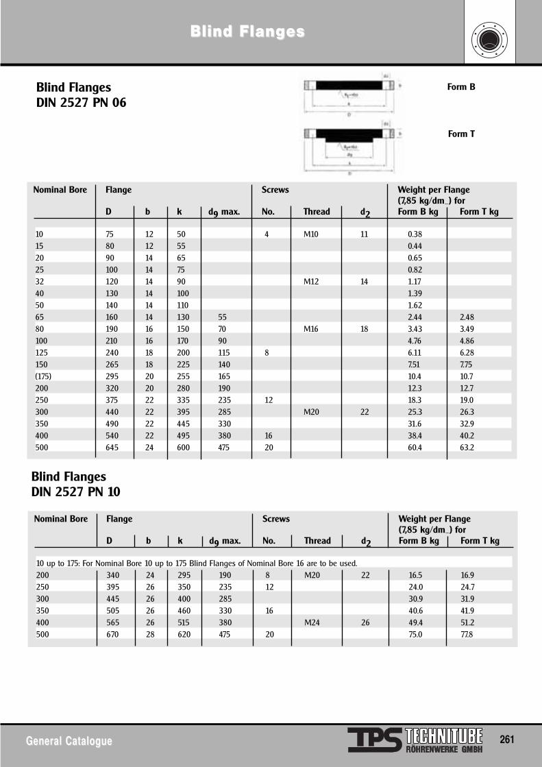
Blind FlangBlind Flangeses
General CatalogueGeneral Catalogue 261
Blind FlangesDIN 2527 PN 06
Blind FlangesDIN 2527 PN 10
Form B
Form T
Nominal Bore Flange Screws Weight per Flange(7,85 kg/dm_) for
D b k d9 max. No. Thread d2 Form B kg Form T kg
10 75 12 50 4 M10 11 0.3815 80 12 55 0.4420 90 14 65 0.6525 100 14 75 0.8232 120 14 90 M12 14 1.1740 130 14 100 1.3950 140 14 110 1.6265 160 14 130 55 2.44 2.4880 190 16 150 70 M16 18 3.43 3.49100 210 16 170 90 4.76 4.86125 240 18 200 115 8 6.11 6.28150 265 18 225 140 7.51 7.75(175) 295 20 255 165 10.4 10.7200 320 20 280 190 12.3 12.7250 375 22 335 235 12 18.3 19.0300 440 22 395 285 M20 22 25.3 26.3350 490 22 445 330 31.6 32.9400 540 22 495 380 16 38.4 40.2500 645 24 600 475 20 60.4 63.2
Nominal Bore Flange Screws Weight per Flange(7,85 kg/dm_) for
D b k d9 max. No. Thread d2 Form B kg Form T kg
10 up to 175: For Nominal Bore 10 up to 175 Blind Flanges of Nominal Bore 16 are to be used.200 340 24 295 190 8 M20 22 16.5 16.9250 395 26 350 235 12 24.0 24.7300 445 26 400 285 30.9 31.9350 505 26 460 330 16 40.6 41.9400 565 26 515 380 M24 26 49.4 51.2500 670 28 620 475 20 75.0 77.8
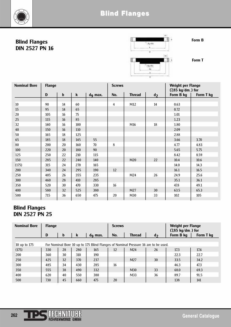
Blind FlangBlind Flangeses
262 General CatalogueGeneral Catalogue
Blind FlangesDIN 2527 PN 16
Blind FlangesDIN 2527 PN 25
Nominal Bore Flange Screws Weight per Flange(7,85 kg/dm_) for
D b k d9 max. No. Thread d2 Form B kg Form T kg
10 90 14 60 4 M12 14 0.6315 95 14 65 0.7220 105 16 75 1.0125 115 16 85 1.2332 140 16 100 M16 18 1.8040 150 16 110 2.0950 165 18 125 2.8865 185 18 145 55 3.66 3.7080 200 20 160 70 8 4.77 4.83100 220 20 180 90 5.65 5.75125 250 22 210 115 8.42 8.59150 285 22 240 140 M20 22 10.4 10.6(175) 315 24 270 165 14.0 14.3200 340 24 295 190 12 16.1 16.5250 405 26 355 235 M24 26 24.9 25.6300 460 28 410 285 35.1 36.1350 520 30 470 330 16 47.8 49.1400 580 32 525 380 M27 30 63.5 65.3500 715 36 650 475 20 M30 33 102 105
Nominal Bore Flange Screws Weight per Flange(7,85 kg/dm_) for
D b k d9 max. No. Thread d2 Form B kg Form T kg
10 up to 175 For Nominal Bore 10 up to 175 Blind Flanges of Nominal Pressure 16 are to be used.(175) 330 28 280 165 12 M24 26 17.3 17.6200 360 30 310 190 22.3 22.7250 425 32 370 237 M27 30 33.5 34.2300 485 34 430 285 16 46.3 47.3350 555 38 490 332 M30 33 68.0 69.3400 620 40 550 380 M33 36 89.7 91.5500 730 45 660 475 20 138 141
Form B
Form T
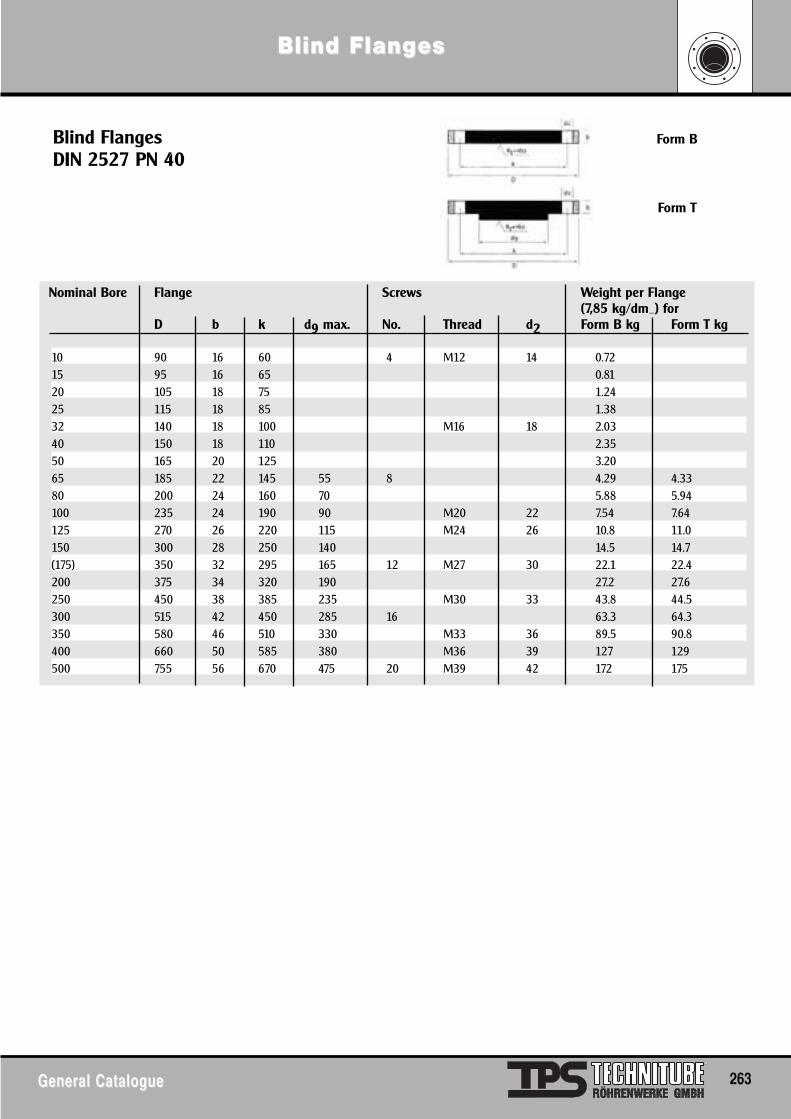
Blind FlangBlind Flangeses
General CatalogueGeneral Catalogue 263
Blind FlangesDIN 2527 PN 40
Nominal Bore Flange Screws Weight per Flange(7,85 kg/dm_) for
D b k d9 max. No. Thread d2 Form B kg Form T kg
10 90 16 60 4 M12 14 0.7215 95 16 65 0.8120 105 18 75 1.2425 115 18 85 1.3832 140 18 100 M16 18 2.0340 150 18 110 2.3550 165 20 125 3.2065 185 22 145 55 8 4.29 4.3380 200 24 160 70 5.88 5.94100 235 24 190 90 M20 22 7.54 7.64125 270 26 220 115 M24 26 10.8 11.0150 300 28 250 140 14.5 14.7(175) 350 32 295 165 12 M27 30 22.1 22.4200 375 34 320 190 27.2 27.6250 450 38 385 235 M30 33 43.8 44.5300 515 42 450 285 16 63.3 64.3350 580 46 510 330 M33 36 89.5 90.8400 660 50 585 380 M36 39 127 129500 755 56 670 475 20 M39 42 172 175
Form B
Form T
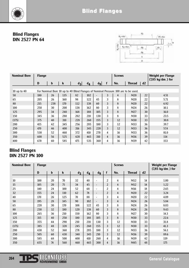
Blind FlangBlind Flangeses
264 General CatalogueGeneral Catalogue
Blind FlangesDIN 2527 PN 64
Blind FlangesDIN 2527 PN 100
Nominal Bore Flange Screws Weight per Flange(7,85 kg/dm_) for
D b k d3 d4 d9 f No. Thread d2
10 up to 40 For Nominal Bore 10 up to 40 Blind Flanges of Nominal Pressure 100 are to be used.50 180 26 135 82 102 - 3 4 M20 22 4.5165 205 26 160 98 122 45 3 8 M20 22 5.7180 215 238 170 112 138 60 3 8 M20 22 6.92100 250 30 200 138 162 80 3 8 M24 26 10.1125 295 34 240 168 188 105 3 8 M27 30 16.0150 345 36 280 202 218 130 3 8 M30 33 23.5(175) 375 40 310 228 260 155 3 12 M30 33 30.8200 415 42 345 256 285 180 3 12 M33 36 39.7250 470 46 400 316 345 220 3 12 M33 36 57.4300 530 52 460 372 410 270 4 16 M33 36 81.0350 600 56 525 420 465 310 4 16 M36 39 114400 670 60 585 475 535 360 4 16 M39 42 153
Nominal Bore Flange Screws Weight per Flange(7,85 kg/dm_) for
D b k d3 d4 d9 f No. Thread d2
10 100 20 70 32 40 - 2 4 M12 14 1.0015 105 20 75 34 45 - 2 4 M12 14 1.2225 140 24 100 52 68 - 2 4 M16 18 2.6532 155 24 110 62 78 - 2 4 M20 22 3.2440 170 26 125 70 88 - 3 4 M20 22 4.0950 195 28 145 90 102 - 3 4 M24 26 5.8465 220 30 170 108 122 45 3 8 M24 26 8.0380 230 32 180 120 138 60 3 8 M24 26 9.43100 265 36 210 150 162 80 3 8 M27 30 14.3125 315 40 250 180 188 105 3 8 M30 33 22.6150 355 44 290 210 218 130 3 12 M30 33 31.8(175) 385 48 320 245 260 155 3 12 M30 33 41.3200 430 52 360 278 285 180 3 12 M33 36 56.1250 505 60 430 340 345 210 3 12 M36 39 89.6300 585 68 500 400 410 260 4 16 M39 42 119350 655 74 560 460 465 300 4 16 M45 48 175
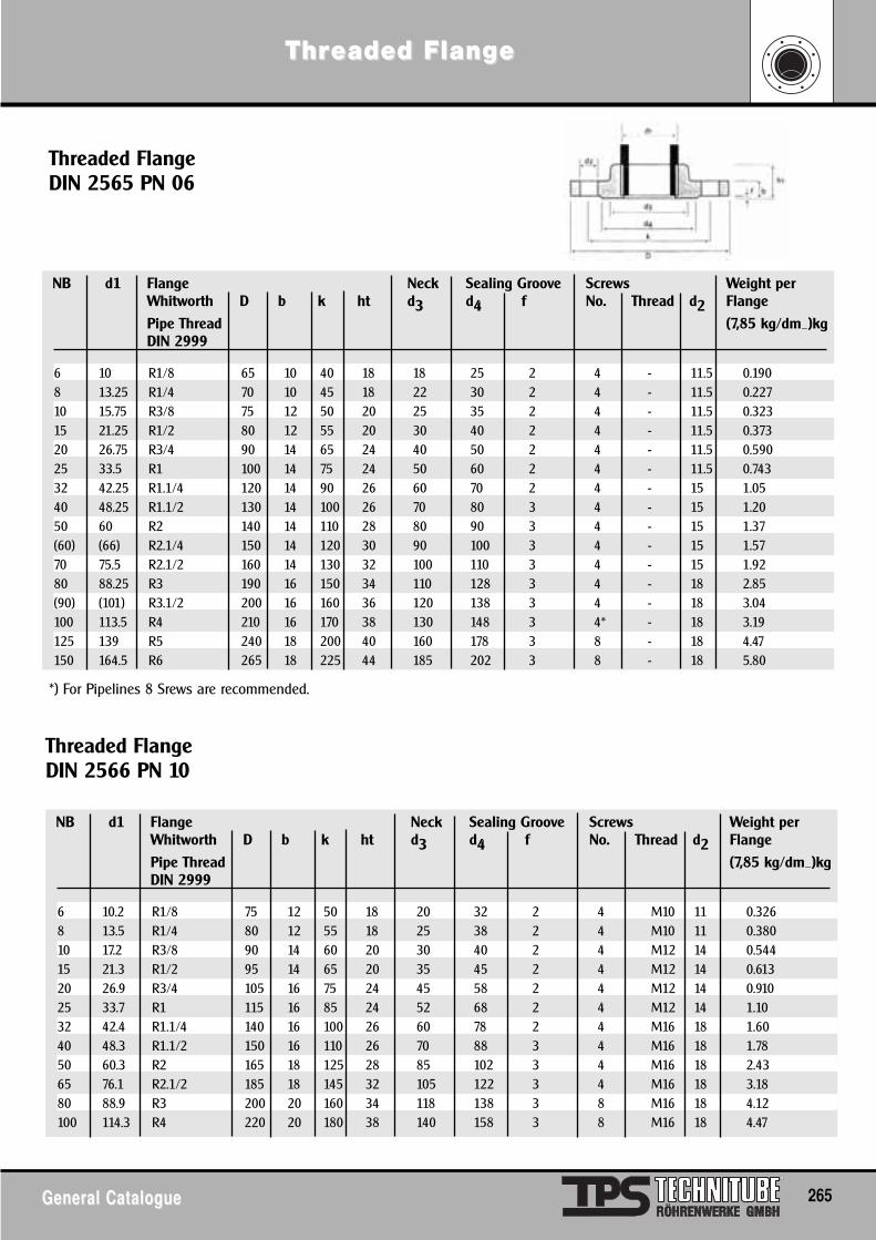
ThrThreaded Flangeaded Flangee
General CatalogueGeneral Catalogue 265
Threaded FlangeDIN 2565 PN 06
Threaded FlangeDIN 2566 PN 10
NB d1 Flange Neck Sealing Groove Screws Weight perWhitworth D b k ht d3 d4 f No. Thread d2 Flange
Pipe Thread (7,85 kg/dm_)kgDIN 2999
6 10 R1/8 65 10 40 18 18 25 2 4 - 11.5 0.1908 13.25 R1/4 70 10 45 18 22 30 2 4 - 11.5 0.22710 15.75 R3/8 75 12 50 20 25 35 2 4 - 11.5 0.32315 21.25 R1/2 80 12 55 20 30 40 2 4 - 11.5 0.37320 26.75 R3/4 90 14 65 24 40 50 2 4 - 11.5 0.59025 33.5 R1 100 14 75 24 50 60 2 4 - 11.5 0.74332 42.25 R1.1/4 120 14 90 26 60 70 2 4 - 15 1.0540 48.25 R1.1/2 130 14 100 26 70 80 3 4 - 15 1.2050 60 R2 140 14 110 28 80 90 3 4 - 15 1.37(60) (66) R2.1/4 150 14 120 30 90 100 3 4 - 15 1.5770 75.5 R2.1/2 160 14 130 32 100 110 3 4 - 15 1.9280 88.25 R3 190 16 150 34 110 128 3 4 - 18 2.85(90) (101) R3.1/2 200 16 160 36 120 138 3 4 - 18 3.04100 113.5 R4 210 16 170 38 130 148 3 4* - 18 3.19125 139 R5 240 18 200 40 160 178 3 8 - 18 4.47150 164.5 R6 265 18 225 44 185 202 3 8 - 18 5.80
*) For Pipelines 8 Srews are recommended.
NB d1 Flange Neck Sealing Groove Screws Weight perWhitworth D b k ht d3 d4 f No. Thread d2 Flange
Pipe Thread (7,85 kg/dm_)kgDIN 2999
6 10.2 R1/8 75 12 50 18 20 32 2 4 M10 11 0.3268 13.5 R1/4 80 12 55 18 25 38 2 4 M10 11 0.38010 17.2 R3/8 90 14 60 20 30 40 2 4 M12 14 0.54415 21.3 R1/2 95 14 65 20 35 45 2 4 M12 14 0.61320 26.9 R3/4 105 16 75 24 45 58 2 4 M12 14 0.91025 33.7 R1 115 16 85 24 52 68 2 4 M12 14 1.1032 42.4 R1.1/4 140 16 100 26 60 78 2 4 M16 18 1.6040 48.3 R1.1/2 150 16 110 26 70 88 3 4 M16 18 1.7850 60.3 R2 165 18 125 28 85 102 3 4 M16 18 2.4365 76.1 R2.1/2 185 18 145 32 105 122 3 4 M16 18 3.1880 88.9 R3 200 20 160 34 118 138 3 8 M16 18 4.12100 114.3 R4 220 20 180 38 140 158 3 8 M16 18 4.47
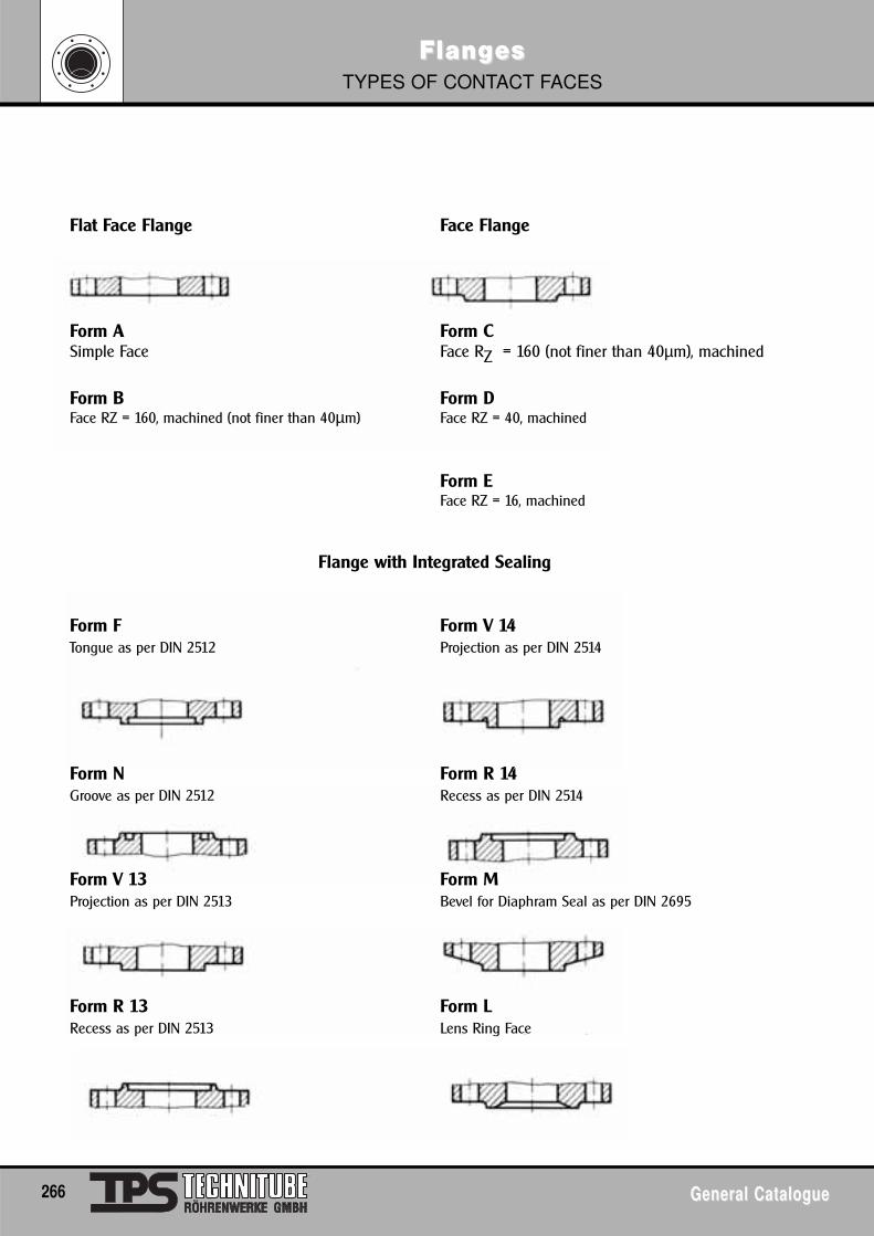
FlangFlangesesTYPES OF CONTACT FACES
266 General CatalogueGeneral Catalogue
Flat Face Flange Face Flange
Form A Form CSimple Face Face RZ = 160 (not finer than 40µm), machined
Form B Form DFace RZ = 160, machined (not finer than 40µm) Face RZ = 40, machined
Form EFace RZ = 16, machined
Flange with Integrated Sealing
Form F Form V 14Tongue as per DIN 2512 Projection as per DIN 2514
Form N Form R 14Groove as per DIN 2512 Recess as per DIN 2514
Form V 13 Form MProjection as per DIN 2513 Bevel for Diaphram Seal as per DIN 2695
Form R 13 Form LRecess as per DIN 2513 Lens Ring Face
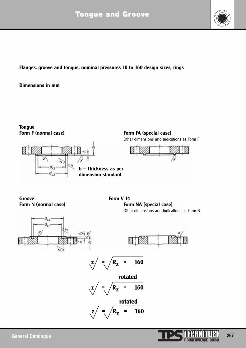
TTongue and Grongue and Groooovvee
General CatalogueGeneral Catalogue 267
Flanges, groove and tongue, nominal pressures 10 to 160 design sizes, rings
Dimensions in mm
TongueForm F (normal case) Form FA (special case)
Other dimensions and indications as Form F
b = Thickness as perdimension standard
Groove Form V 14Form N (normal case) Form NA (special case)
Other dimensions and indications as Form N
z = Rz = 160
z = Rz = 160
z = Rz = 160
rotated
rotated
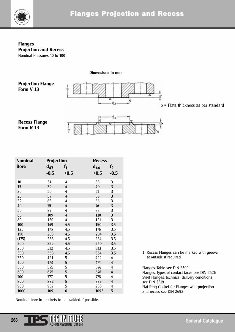
FlangFlanges Pres Projection and Rojection and Recessecess
268 General CatalogueGeneral Catalogue
FlangesProjection and RecessNominal Pressures 10 to 100
Dimensions in mm
Projection FlangeForm V 13
b = Plate thickness as per standard
Recess FlangeForm R 13
Nominal Projection RecessBore d43 f1 d44 f2
-0.5 +0.5 +0.5 -0.5
10 34 4 35 315 39 4 40 320 50 4 51 325 57 4 58 332 65 4 66 340 75 4 76 350 87 4 88 365 109 4 110 380 120 4 121 3100 149 4.5 150 3.5125 175 4.5 176 3.5150 203 4.5 204 3.5(175) 233 4.5 234 3.5200 259 4.5 260 3.5250 312 4.5 313 3.5300 363 4.5 364 3.5350 421 5 422 4400 473 5 474 4500 575 5 576 4600 675 5 676 4700 777 5 778 4800 882 5 883 4900 987 5 988 41000 1091 6 1092 5
Nominal bore in brackets to be avoided if possible.
1) Recess Flanges can be marked with grooveat outside if required
Flanges, Table see DIN 2500Flanges, Types of contact faces see DIN 2526Steel Flanges, technical delivery conditionssee DIN 2519Flat Ring Gasket for Flanges with projectionand recess see DIN 2692
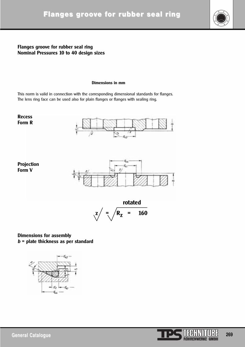
FlangFlanges ges grroooovve fe for ror rubber seal rubber seal ringing
General CatalogueGeneral Catalogue 269
Flanges groove for rubber seal ringNominal Pressures 10 to 40 design sizes
Dimensions in mm
This norm is valid in connection with the corresponding dimensional standards for flanges.The lens ring face can be used also for plain flanges or flanges with sealing ring.
RecessForm R
ProjectionForm V
Dimensions for assemblyb = plate thickness as per standard
z = Rz = 160
rotated
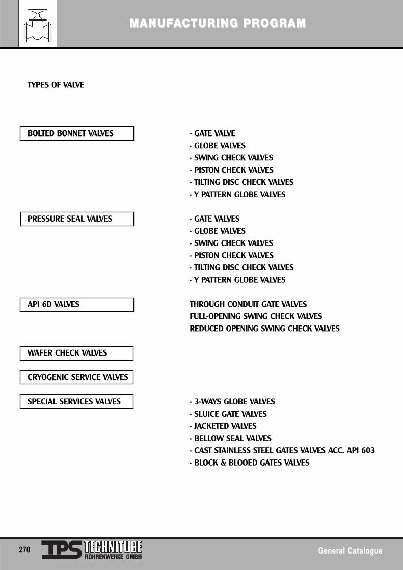
MANUFMANUFAACTURINCTURING PRG PROGRAMOGRAM
270 General CatalogueGeneral Catalogue
TYPES OF VALVE
BOLTED BONNET VALVES • GATE VALVE• GLOBE VALVES• SWING CHECK VALVES• PISTON CHECK VALVES• TILTING DISC CHECK VALVES• Y PATTERN GLOBE VALVES
PRESSURE SEAL VALVES • GATE VALVES• GLOBE VALVES• SWING CHECK VALVES• PISTON CHECK VALVES• TILTING DISC CHECK VALVES• Y PATTERN GLOBE VALVES
API 6D VALVES THROUGH CONDUIT GATE VALVESFULL-OPENING SWING CHECK VALVESREDUCED OPENING SWING CHECK VALVES
WAFER CHECK VALVES
CRYOGENIC SERVICE VALVES
SPECIAL SERVICES VALVES • 3-WAYS GLOBE VALVES• SLUICE GATE VALVES• JACKETED VALVES• BELLOW SEAL VALVES• CAST STAINLESS STEEL GATES VALVES ACC. API 603• BLOCK & BLOOED GATES VALVES
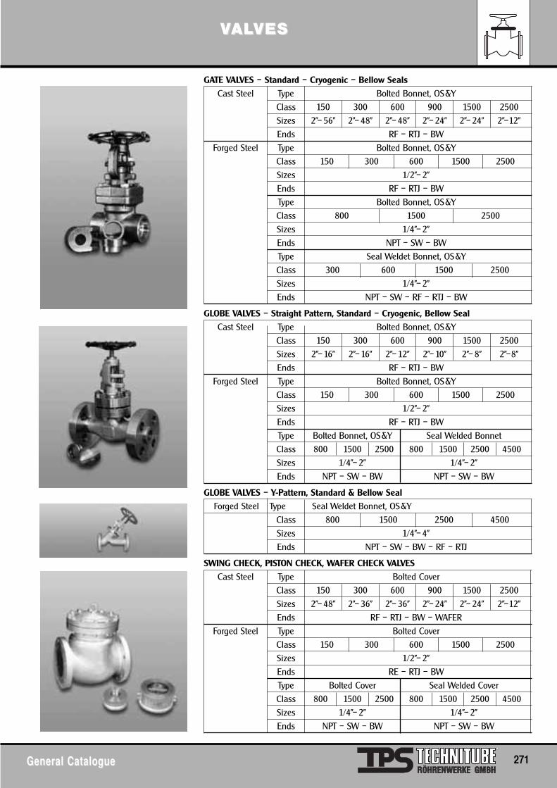
VVALALVESVES
General CatalogueGeneral Catalogue 271
GATE VALVES – Standard – Cryogenic – Bellow Seals
Cast Steel Type Bolted Bonnet, OS&Y
Class 150 300 600 900 1500 2500
Sizes 2”– 56” 2”– 48” 2”– 48” 2”– 24” 2”– 24” 2”–12”
Ends RF – RTJ – BW
Forged Steel Type Bolted Bonnet, OS&Y
Class 150 300 600 1500 2500
Sizes 1/2”– 2”
Ends RF – RTJ – BW
Type Bolted Bonnet, OS&Y
Class 800 1500 2500
Sizes 1/4”– 2”
Ends NPT – SW – BW
Type Seal Weldet Bonnet, OS&Y
Class 300 600 1500 2500
Sizes 1/4”– 2”
Ends NPT – SW – RF – RTJ – BW
GLOBE VALVES – Straight Pattern, Standard – Cryogenic, Bellow Seal
Cast Steel Type Bolted Bonnet, OS&Y
Class 150 300 600 900 1500 2500
Sizes 2”– 16” 2”– 16” 2”– 12” 2”– 10” 2”– 8” 2”–8”
Ends RF – RTJ – BW
Forged Steel Type Bolted Bonnet, OS&Y
Class 150 300 600 1500 2500
Sizes 1/2”– 2”
Ends RF – RTJ – BW
Type Bolted Bonnet, OS&Y Seal Welded Bonnet
Class 800 1500 2500 800 1500 2500 4500
Sizes 1/4”– 2” 1/4”– 2”
Ends NPT – SW – BW NPT – SW – BW
GLOBE VALVES – Y-Pattern, Standard & Bellow Seal
Forged Steel Type Seal Weldet Bonnet, OS&Y
Class 800 1500 2500 4500
Sizes 1/4”– 4”
Ends NPT – SW – BW – RF – RTJ
SWING CHECK, PISTON CHECK, WAFER CHECK VALVES
Cast Steel Type Bolted Cover
Class 150 300 600 900 1500 2500
Sizes 2”– 48” 2”– 36” 2”– 36” 2”– 24” 2”– 24” 2”–12”
Ends RF – RTJ – BW – WAFER
Forged Steel Type Bolted Cover
Class 150 300 600 1500 2500
Sizes 1/2”– 2”
Ends RE – RTJ – BW
Type Bolted Cover Seal Welded Cover
Class 800 1500 2500 800 1500 2500 4500
Sizes 1/4”– 2” 1/4”– 2”
Ends NPT – SW – BW NPT – SW – BW
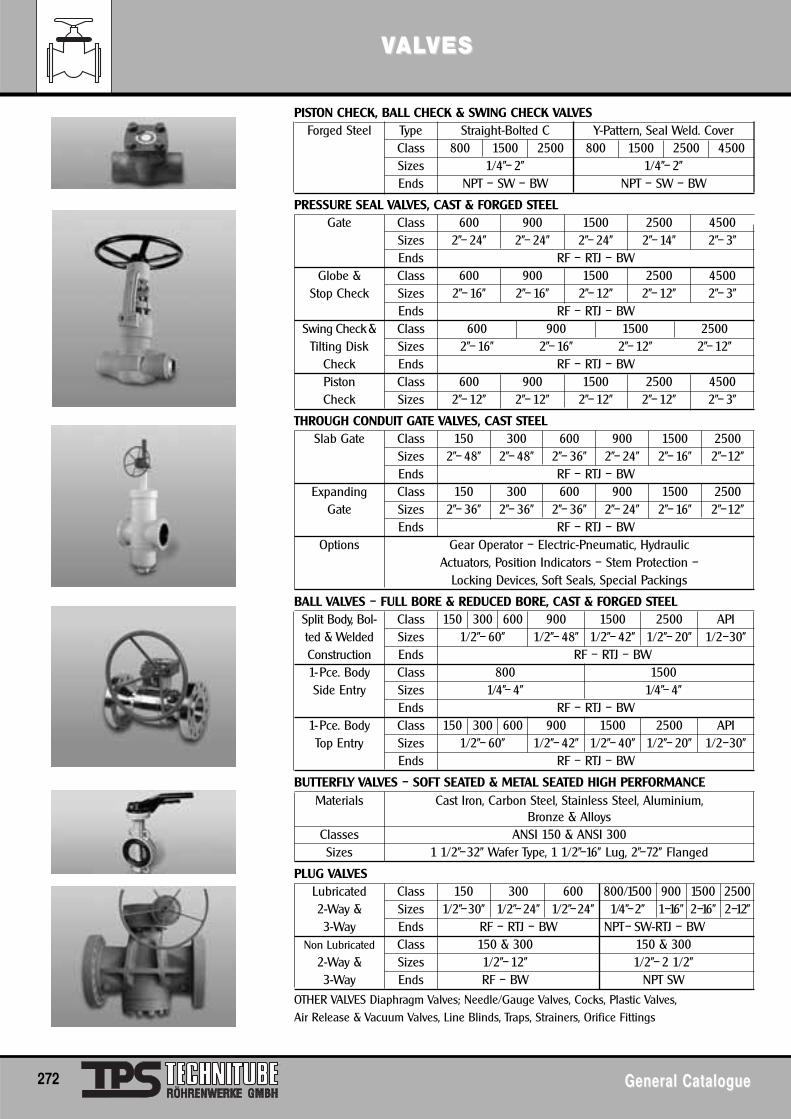
VVALALVESVES
272 General CatalogueGeneral Catalogue
PISTON CHECK, BALL CHECK & SWING CHECK VALVESForged Steel Type Straight-Bolted C Y-Pattern, Seal Weld. Cover
Class 800 1500 2500 800 1500 2500 4500Sizes 1/4”– 2” 1/4”– 2”Ends NPT – SW – BW NPT – SW – BW
PRESSURE SEAL VALVES, CAST & FORGED STEELGate Class 600 900 1500 2500 4500
Sizes 2”– 24” 2”– 24” 2”– 24” 2”– 14” 2”– 3”Ends RF – RTJ – BW
Globe & Class 600 900 1500 2500 4500Stop Check Sizes 2”– 16” 2”– 16” 2”– 12” 2”– 12” 2”– 3”
Ends RF – RTJ – BWSwing Check& Class 600 900 1500 2500
Tilting Disk Sizes 2”– 16” 2”– 16” 2”– 12” 2”– 12”Check Ends RF – RTJ – BWPiston Class 600 900 1500 2500 4500Check Sizes 2”– 12” 2”– 12” 2”– 12” 2”– 12” 2”– 3”
THROUGH CONDUIT GATE VALVES, CAST STEELSlab Gate Class 150 300 600 900 1500 2500
Sizes 2”– 48” 2”– 48” 2”– 36” 2”– 24” 2”– 16” 2”–12”Ends RF – RTJ – BW
Expanding Class 150 300 600 900 1500 2500Gate Sizes 2”– 36” 2”– 36” 2”– 36” 2”– 24” 2”– 16” 2”–12”
Ends RF – RTJ – BWOptions Gear Operator – Electric-Pneumatic, Hydraulic
Actuators, Position Indicators – Stem Protection –Locking Devices, Soft Seals, Special Packings
BALL VALVES – FULL BORE & REDUCED BORE, CAST & FORGED STEELSplit Body, Bol- Class 150 300 600 900 1500 2500 APIted & Welded Sizes 1/2”– 60” 1/2”– 48” 1/2”– 42” 1/2”– 20” 1/2–30”Construction Ends RF – RTJ – BW1-Pce. Body Class 800 1500Side Entry Sizes 1/4”– 4” 1/4”– 4”
Ends RF – RTJ – BW1-Pce. Body Class 150 300 600 900 1500 2500 APITop Entry Sizes 1/2”– 60” 1/2”– 42” 1/2”– 40” 1/2”– 20” 1/2–30”
Ends RF – RTJ – BW
BUTTERFLY VALVES – SOFT SEATED & METAL SEATED HIGH PERFORMANCEMaterials Cast Iron, Carbon Steel, Stainless Steel, Aluminium,
Bronze & AlloysClasses ANSI 150 & ANSI 300Sizes 1 1/2”–32” Wafer Type, 1 1/2”–16” Lug, 2”–72” Flanged
PLUG VALVESLubricated Class 150 300 600 800/1500 900 1500 25002-Way & Sizes 1/2”–30” 1/2”–24” 1/2”–24” 1/4”–2” 1–16” 2–16” 2–12”3-Way Ends RF – RTJ – BW NPT– SW-RTJ – BW
Non Lubricated Class 150 & 300 150 & 3002-Way & Sizes 1/2”– 12” 1/2”– 2 1/2”3-Way Ends RF – BW NPT SW
OTHER VALVES Diaphragm Valves; Needle/Gauge Valves, Cocks, Plastic Valves, Air Release & Vacuum Valves, Line Blinds, Traps, Strainers, Orifice Fittings
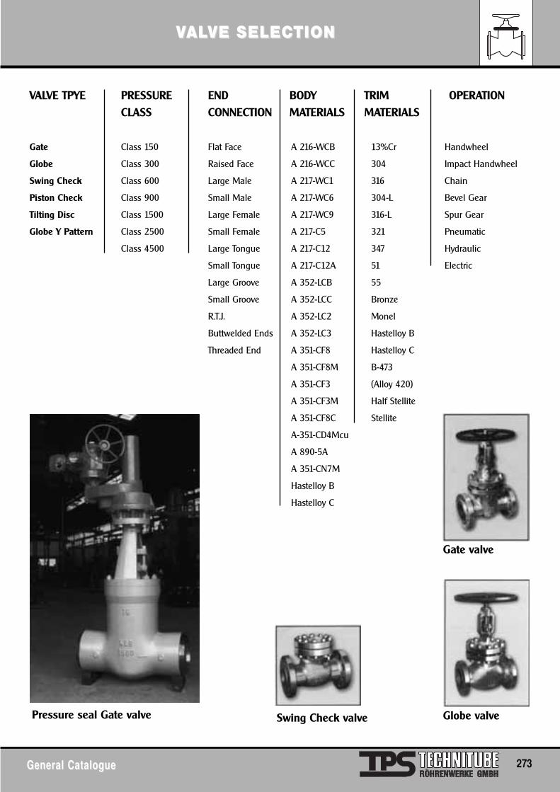
VVALALVE SELECTIONVE SELECTION
General CatalogueGeneral Catalogue 273
VALVE TPYE PRESSURE END BODY TRIM OPERATIONCLASS CONNECTION MATERIALS MATERIALS
Gate Class 150 Flat Face A 216-WCB 13%Cr Handwheel
Globe Class 300 Raised Face A 216-WCC 304 Impact Handwheel
Swing Check Class 600 Large Male A 217-WC1 316 Chain
Piston Check Class 900 Small Male A 217-WC6 304-L Bevel Gear
Tilting Disc Class 1500 Large Female A 217-WC9 316-L Spur Gear
Globe Y Pattern Class 2500 Small Female A 217-C5 321 Pneumatic
Class 4500 Large Tongue A 217-C12 347 Hydraulic
Small Tongue A 217-C12A 51 Electric
Large Groove A 352-LCB 55
Small Groove A 352-LCC Bronze
R.T.J. A 352-LC2 Monel
Buttwelded Ends A 352-LC3 Hastelloy B
Threaded End A 351-CF8 Hastelloy C
A 351-CF8M B-473
A 351-CF3 (Alloy 420)
A 351-CF3M Half Stellite
A 351-CF8C Stellite
A-351-CD4Mcu
A 890-5A
A 351-CN7M
Hastelloy B
Hastelloy C
Pressure seal Gate valve Swing Check valve Globe valve
Gate valve
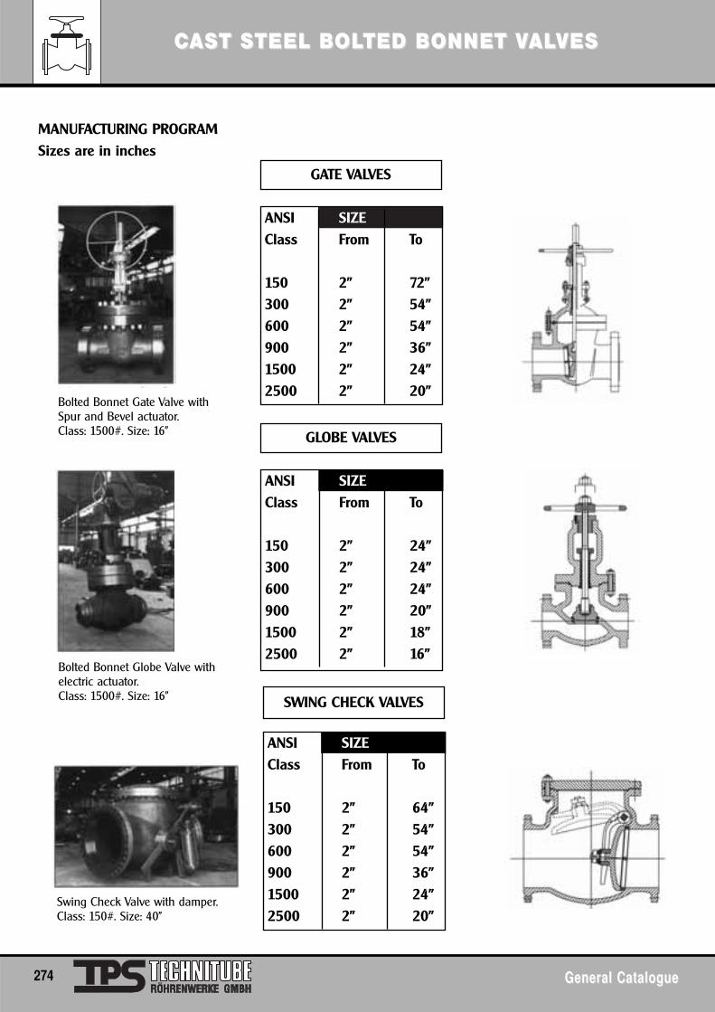
CCASAST ST STEEL BTEEL BOLOLTED BTED BONNET VONNET VALALVESVES
274 General CatalogueGeneral Catalogue
MANUFACTURING PROGRAMSizes are in inches
GATE VALVES
ANSI SIZEClass From To
150 2" 72"300 2" 54"600 2" 54"900 2" 36"1500 2" 24"2500 2" 20"
GLOBE VALVES
ANSI SIZEClass From To
150 2" 24"300 2" 24"600 2" 24"900 2" 20"1500 2" 18"2500 2" 16"
SWING CHECK VALVES
ANSI SIZEClass From To
150 2" 64"300 2" 54"600 2" 54"900 2" 36"1500 2" 24"2500 2" 20"
Bolted Bonnet Gate Valve withSpur and Bevel actuator.Class: 1500#. Size: 16"
Bolted Bonnet Globe Valve withelectric actuator.Class: 1500#. Size: 16”
Swing Check Valve with damper.Class: 150#. Size: 40"
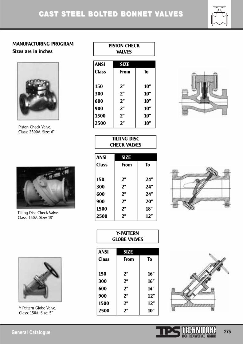
CCASAST ST STEEL BTEEL BOLOLTED BTED BONNET VONNET VALALVESVES
General CatalogueGeneral Catalogue 275
MANUFACTURING PROGRAMSizes are in inches
PISTON CHECKVALVES
ANSI SIZEClass From To
150 2" 10"300 2" 10"600 2" 10"900 2" 10"1500 2" 10"2500 2" 10"
TILTING DISCCHECK VALVES
ANSI SIZEClass From To
150 2" 24"300 2" 24"600 2" 24"900 2" 20"1500 2" 18"2500 2" 12"
Y-PATTERNGLOBE VALVES
ANSI SIZEClass From To
150 2" 16"300 2" 16"600 2" 14"900 2" 12"1500 2" 12"2500 2" 10"
Piston Check Valve.Class: 2500#. Size: 6"
Tilting Disc Check Valve.Class: 150#. Size: 18"
Y Pattern Globe Valve.Class: 150#. Size: 5"
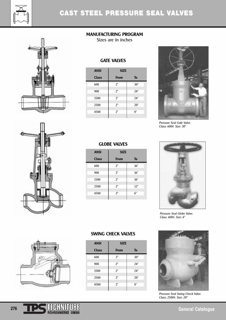
Pressure Seal Gate Valve.Class: 600#. Size: 30"
CCASAST ST STEEL PRESSURE SEAL VTEEL PRESSURE SEAL VALALVESVES
276 General CatalogueGeneral Catalogue
MANUFACTURING PROGRAMSizes are in inches
GATE VALVES
ANSI SIZE
Class From To
600 2" 30"
900 2" 24"
1500 2" 24"
2500 2" 20"
4500 2" 8"
ANSI SIZE
Class From To
600 2" 16"
900 2" 16"
1500 2" 16"
2500 2" 12"
4500 2" 6"
SWING CHECK VALVES
ANSI SIZE
Class From To
600 2" 30"
900 2" 24"
1500 2" 24"
2500 2" 20"
4500 2" 8"
Pressure Seal Swing Check Valve.Class: 2500#. Size: 20"
Pressure Seal Globe Valve.Class: 600#. Size: 6"
GLOBE VALVES
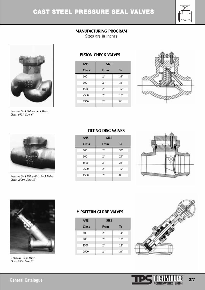
Pressure Seal Piston check Valve.Class: 600#. Size: 6"
Pressure Seal Tilting disc check Valve.Class: 1500#. Size: 10".
Y Pattern Globe Valve.Class: 150#. Size: 6”
CCASAST ST STEEL PRESSURE SEAL VTEEL PRESSURE SEAL VALALVESVES
General CatalogueGeneral Catalogue 277
MANUFACTURING PROGRAMSizes are in inches
ANSI SIZE
Class From To
600 2" 16"
900 2" 16"
1500 2" 16"
2500 2" 12"
4500 2" 8"
ANSI SIZE
Class From To
600 2" 30"
900 2" 24"
1500 2" 24"
2500 2" 16"
4500 2" 8
Y PATTERN GLOBE VALVES
ANSI SIZE
Class From To
600 2" 14"
900 2" 12"
1500 2" 12"
2500 2" 10"
TILTING DISC VALVES
PISTON CHECK VALVES
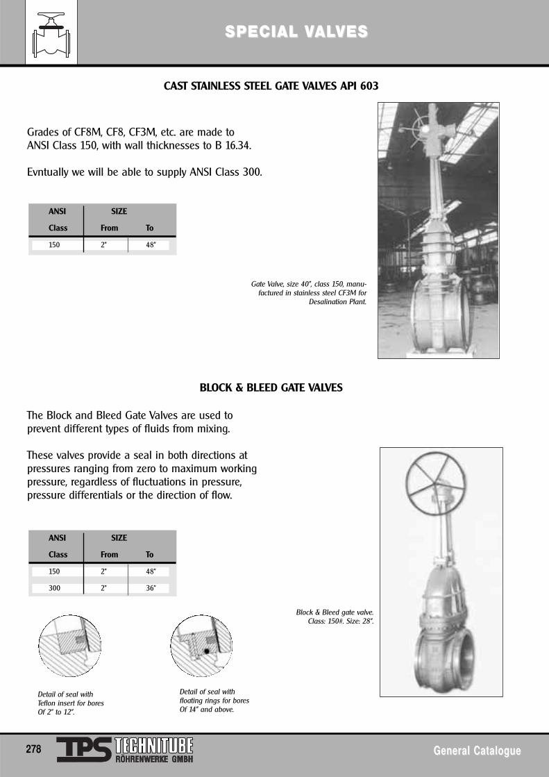
SPECIAL VSPECIAL VALALVESVES
278 General CatalogueGeneral Catalogue
Gate Valve, size 40", class 150, manu-factured in stainless steel CF3M for
Desalination Plant.
Block & Bleed gate valve.Class: 150#. Size: 28".
Detail of seal withTeflon insert for boresOf 2" to 12".
CAST STAINLESS STEEL GATE VALVES API 603
Grades of CF8M, CF8, CF3M, etc. are made toANSI Class 150, with wall thicknesses to B 16.34.
Evntually we will be able to supply ANSI Class 300.
ANSI SIZE
Class From To
150 2" 48"
The Block and Bleed Gate Valves are used toprevent different types of fluids from mixing.
These valves provide a seal in both directions atpressures ranging from zero to maximum workingpressure, regardless of fluctuations in pressure,pressure differentials or the direction of flow.
ANSI SIZE
Class From To
150 2" 48"
300 2" 36"
Detail of seal withfloating rings for boresOf 14" and above.
BLOCK & BLEED GATE VALVES
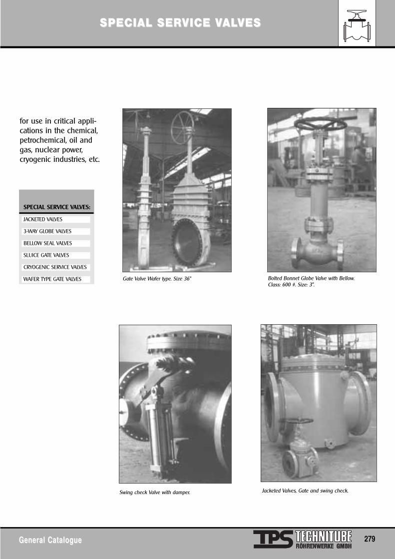
SPECIAL SERVICE VSPECIAL SERVICE VALALVESVES
General CatalogueGeneral Catalogue 279
for use in critical appli-cations in the chemical,petrochemical, oil andgas, nuclear power, cryogenic industries, etc.
SPECIAL SERVICE VALVES:
JACKETED VALVES
3-WAY GLOBE VALVES
BELLOW SEAL VALVES
SLUICE GATE VALVES
CRYOGENIC SERVICE VALVES
WAFER TYPE GATE VALVES Gate Valve Wafer type. Size 36"
Swing check Valve with damper.
Bolted Bonnet Globe Valve with Bellow.Class: 600 #. Size: 3".
Jacketed Valves, Gate and swing check.
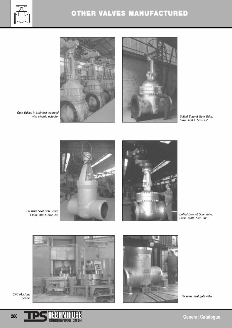
OOTHER VTHER VALALVES MANUFVES MANUFAACTUREDCTURED
280 General CatalogueGeneral Catalogue
Gate Valves in stainless eqippedwith electric actuator Bolted Bonnet Gate Valve.
Class: 600 #. Size: 48".
Pressure Seal Gate valve.Class: 600 #. Size: 24"
CNC MachineCentre.
Bolted Bonnet Gate Valve.Class: 900#. Size: 20".
Pressure seal gate valve
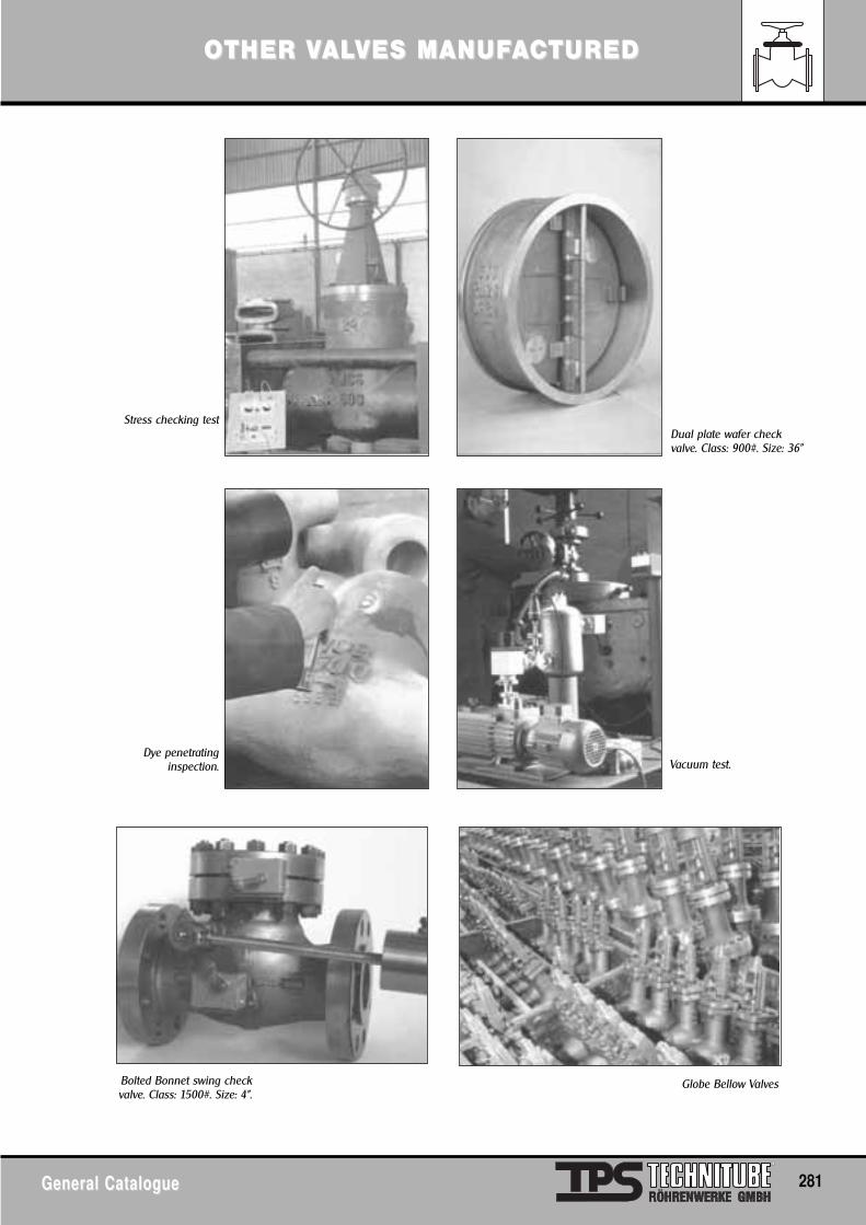
OOTHER VTHER VALALVES MANUFVES MANUFAACTUREDCTURED
General CatalogueGeneral Catalogue 281
Stress checking testDual plate wafer checkvalve. Class: 900#. Size: 36"
Dye penetratinginspection.
Bolted Bonnet swing checkvalve. Class: 1500#. Size: 4".
Vacuum test.
Globe Bellow Valves
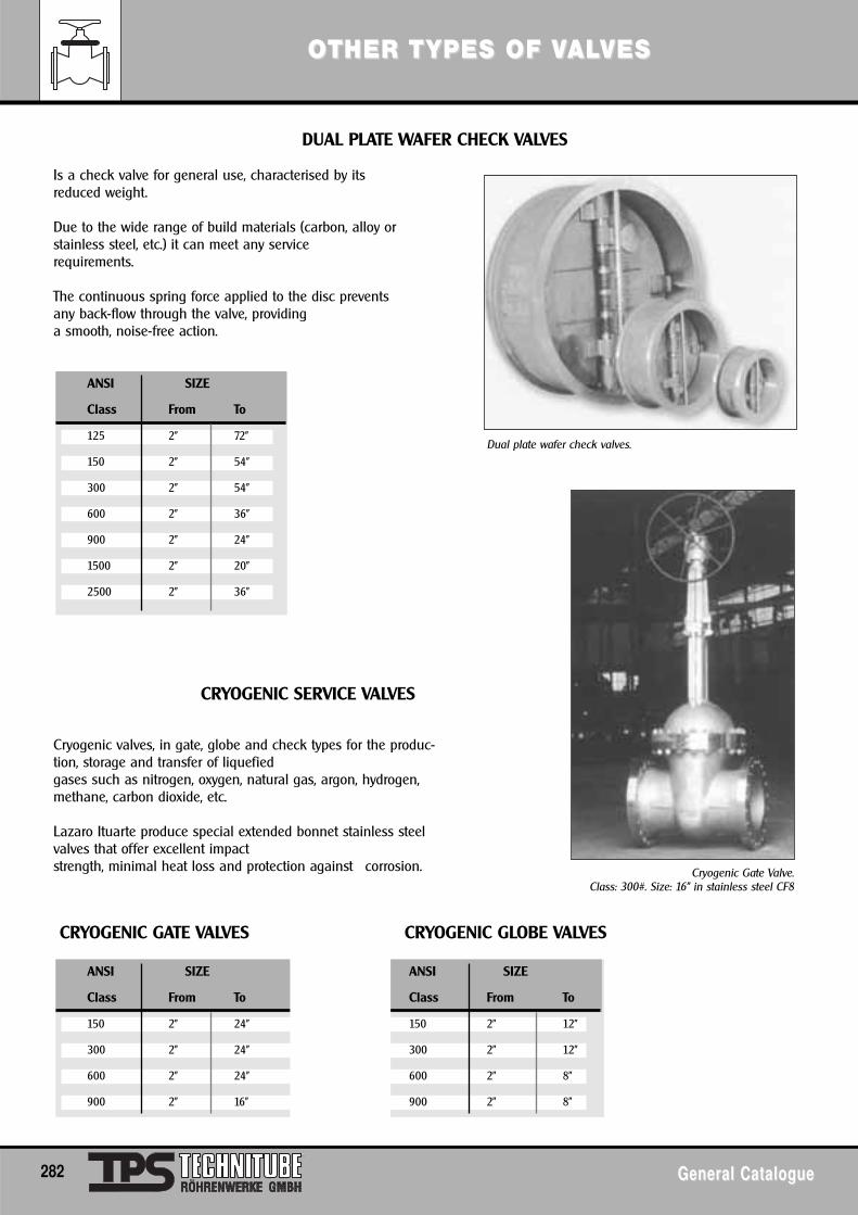
OOTHER TTHER T YPES OF VYPES OF VALALVESVES
282 General CatalogueGeneral Catalogue
Dual plate wafer check valves.
DUAL PLATE WAFER CHECK VALVES
CRYOGENIC SERVICE VALVES
CRYOGENIC GATE VALVES CRYOGENIC GLOBE VALVES
Is a check valve for general use, characterised by itsreduced weight.
Due to the wide range of build materials (carbon, alloy orstainless steel, etc.) it can meet any servicerequirements.
The continuous spring force applied to the disc preventsany back-flow through the valve, providinga smooth, noise-free action.
Cryogenic valves, in gate, globe and check types for the produc-tion, storage and transfer of liquefiedgases such as nitrogen, oxygen, natural gas, argon, hydrogen,methane, carbon dioxide, etc.
Lazaro Ituarte produce special extended bonnet stainless steelvalves that offer excellent impactstrength, minimal heat loss and protection against corrosion.
ANSI SIZE
Class From To
125 2" 72"
150 2" 54"
300 2" 54"
600 2" 36"
900 2" 24"
1500 2" 20"
2500 2" 36"
ANSI SIZE ANSI SIZE
Class From To Class From To
150 2" 24" 150 2" 12"
300 2" 24" 300 2" 12"
600 2" 24" 600 2" 8"
900 2" 16" 900 2" 8"
Cryogenic Gate Valve.Class: 300#. Size: 16" in stainless steel CF8
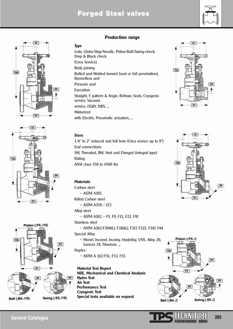
FFororgged Sed Stteel veel valalvveses
General CatalogueGeneral Catalogue 283
Production range
TypeGate, Globe/Stop/Needle, Piston/Ball/Swing-check, Drop & Block check(Urea Service)Body joiningBolted and Welded bonnet (seal or full penetration),Bonnetless andPressure sealExecutionStraight, Y pattern & Angle, Bellows Seals, Cryogenicservice, Vacuumservice, OS&Y, ISRS, ...Motorizedwith Electric, Pneumatic actuators, ...
Sizes1/4" to 2" reduced and full bore (Urea service up to 8")End connectionsSW, Threaded, BW, Hub and Flanged (integral type)RatingANSI class 150 to 4500 lbs
MaterialsCarbon steel
– ASTM A105Killed Carbon steel
– ASTM A350 / LF2Alloy steel
– ASTM A182 – F5, F9, F11, F22, F91Stainless steel
– ASTM A182/F304(L), F316(L), F317, F321, F347, F44Special Alloy
– Monel, Inconel, Incoloy, Hastelloy, UNS, Alloy 20,Sanicro 28, Titanium, ...
Duplex – ASTM A 182/F51, F53, F55
Material Test ReportNDE, Mechanical and Chemical AnalysisHydro TestAir TestPerformance TestCryogenic TestSpecial tests available on request
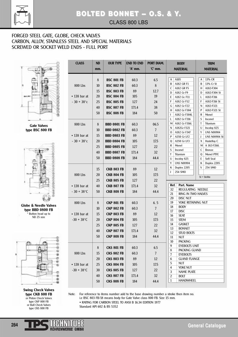
BBOLOLTED BTED BONNET – O.S. & YONNET – O.S. & Y. . CLASS 800 LBS
284 General CatalogueGeneral Catalogue
CLASS ND OUR TYPE END TO END PORT DIAM.
mm. ‘A‘ mm. ‘C‘ mm.
8 BSC 801 FB 60.3 6.5
800 Lbs 10 BSC 802 FB 60.3 8
15 BSC 803 FB 89 12.7• 138 bar at 20 BSC 804 FB 105 19
- 30 + 38°c 25 BSC 805 FB 127 24
40 BSC 807 FB 171.4 38
50 BSC 808 FB 184 50
800 Lbs 8 BBD 0801 FB 60.3 06.5
10 BBD 0802 FB 60.3 7
• 138 bar at 15 BBD 0803 FB 89 12
- 30 + 38°c 20 BBD 0804 FB 105 17.5
25 BBD 0805 FB 127 22
40 BBD 0807 FB 171.4 32
50 BBD 0808 FB 184 44.4
15 CKB 803 FB 89 12
800 Lbs 20 CKB 804 FB 105 17.5
25 CKB 805 FB 127 22
• 138 bar at 40 CKB 807 FB 171.4 32
- 30 + 38°C 50 CKB 808 FB 184 44.4
800 Lbs 8 CKP 801 FB 60.3 6. 5
10 CKP 802 FB 60.3 7
• 138 bar at 15 CKP 803 FB 89 12
-30 + 38°C 20 CKP 804 FB 105 17.5
25 CKP 805 FB 127 22
40 CKP 807 FB 171.4 32
50 CKP 808 FB 184 44.4
8 CKS 801 FB 60.3 6.5
800 Lbs 15 CKS 802 FB 60.3 7
20 CKS 803 FB 89 12
• 138 bar at 25 CKS 804 FB 105 17.5
-30 + 38°C 30 CKS 805 FB 127 22
40 CKS 807 FB 171.4 32
50 CKS 808 FB 184 44.4
FORGED STEEL GATE, GLOBE, CHECK VALVESCARBON, ALLOY, STAINLESS STEEL AND SPECIAL MATERIALSSCREWED OR SOCKET WELD ENDS - FULL PORT
Note: For reference to items number add to the base drawing number a stroke then item no.i.e BSC 803 FB/18 means body for Gate Valve class 800 FB. Size 15 mm.• RATING FOR CARBON STEEL TO ANSI B 16.34 EDITION 1977Standard API 602 & BS 5352
Gate Valvestype BSC 800 FB
Globe & Needle Valvestype BBD 0800 FB
* Button head up to ND 25 size
Swing Check Valvestype CKB 800 FB or Piston Check Valves
type CKP 800 FBor Ball Check Valves
type CKS 800 FB
A A105
B A182 GR F1
C A182 GR F5
D A182 Gr F9
E A182 Gr. F11
F A182 Gr F12
G A182 Gr F22
H A182 Gr F304
I A182 Gr F304L
L A182 Gr F316
M A182 Gr F316L
N A182Gr F321
O A182 Gr F347
P A350 Gr LF2
Q A350 Gr LF3
R Monel
S Inconel
T Titanium
U Incoloy 825
Y UNS N08904
K Duplex 2205
J 254 SMO
BODY
MATERIAL
TRIM
MATERIAL
Ref. Part. Name32 REGULATING NEEDLE21 RING IN TWO HALVES20 DISC NUT19 YOKE RETAINING NUT18 BODY17 DISC16 SEAT15 STEM14 GASKET13 BONNET12 STUD BOLTS11 NUT10 PACKING9 EYEBOLTS UNIT8 PACKING GLAND7 EYEBOLTS6 GLAND FLANGE5 NUT4 YOKE NUT3 NAME PLATE2 BOLT1 HANDWHEEL
A 13% CR
B 13% Cr St
H A182-F304
D A182-F304 St
L A182-F316
F A182-F316 St
N A182-F321
P A182-F321 St
R Monel
S Inconel
T Titanium
U Incoloy 825
Y UNS N08904
J UNS N08904 St
X Hastelloy C
M A 182-F316L
C Bronze
Q Monel PTFE
E Soft Seal
K Duplex 2205
V 254 SMO
St = Stellite
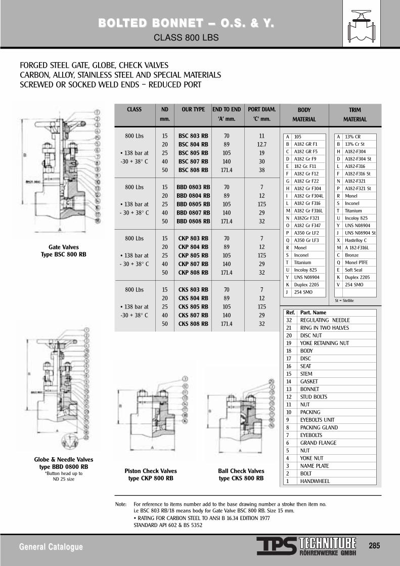
General CatalogueGeneral Catalogue 285
BBOLOLTED BTED BONNET – O.S. & YONNET – O.S. & Y. . CLASS 800 LBS
CLASS ND OUR TYPE END TO END PORT DIAM.
mm. ‘A‘ mm. ‘C‘ mm.
800 Lbs 15 BSC 803 RB 70 1120 BSC 804 RB 89 12.7
• 138 bar at 25 BSC 805 RB 105 19-30 + 38° C 40 BSC 807 RB 140 30
50 BSC 808 RB 171.4 38
800 Lbs 15 BBD 0803 RB 70 720 BBD 0804 RB 89 12
• 138 bar at 25 BBD 0805 RB 105 17.5- 30 + 38° C 40 BBD 0807 RB 140 29
50 BBD 0808 RB 171.4 32
800 Lbs 15 CKP 803 RB 70 720 CKP 804 RB 89 12
• 138 bar at 25 CKP 805 RB 105 17.5- 30 + 38° C 40 CKP 807 RB 140 29
50 CKP 808 RB 171.4 32
800 Lbs 15 CKS 803 RB 70 720 CKS 804 RB 89 12
• 138 bar at 25 CKS 805 RB 105 17.5-30 + 38° C 40 CKS 807 RB 140 29
50 CKS 808 RB 171.4 32
FORGED STEEL GATE, GLOBE, CHECK VALVESCARBON, ALLOY, STAINLESS STEEL AND SPECIAL MATERIALSSCREWED OR SOCKED WELD ENDS – REDUCED PORT
Note: For reference to items number add to the base drawing number a stroke then item no.i.e BSC 803 RB/18 means body for Gate Valve BSC 800 RB. Size 15 mm.• RATING FOR CARBON STEEL TO ANSI B 16.34 EDITION 1977STANDARD API 602 & BS 5352
Gate ValvesType BSC 800 RB
Globe & Needle Valvestype BBD 0800 RB
*Button head up toND 25 size
Piston Check Valvestype CKP 800 RB
Ball Check Valvestype CKS 800 RB
A 105
B A182 GR F1
C A182 GR F5
D A182 Gr F9
E 182 Gr. F11
F A182 Gr F12
G A182 Gr F22
H A182 Gr F304
I A182 Gr F304L
L A182 Gr F316
M A182 Gr F316L
N A182Gr F321
O A182 Gr F347
P A350 Gr LF2
Q A350 Gr LF3
R Monel
S Inconel
T Titanium
U Incoloy 825
Y UNS N08904
K Duplex 2205
J 254 SMO
BODY
MATERIAL
TRIM
MATERIAL
Ref. Part. Name32 REGULATING NEEDLE21 RING IN TWO HALVES20 DISC NUT19 YOKE RETAINING NUT18 BODY17 DISC16 SEAT15 STEM14 GASKET13 BONNET12 STUD BOLTS11 NUT10 PACKING9 EYEBOLTS UNIT8 PACKING GLAND7 EYEBOLTS6 GRAND FLANGE5 NUT4 YOKE NUT3 NAME PLATE2 BOLT1 HANDWHEEL
A 13% CR
B 13% Cr St
H A182-F304
D A182-F304 St
L A182-F316
F A182-F316 St
N A182-F321
P A182-F321 St
R Monel
S Inconel
T Titanium
U Incoloy 825
Y UNS N08904
J UNS N08904 St
X Hastelloy C
M A 182-F316L
C Bronze
Q Monel PTFE
E Soft Seal
K Duplex 2205
V 254 SMO
St = Stellite
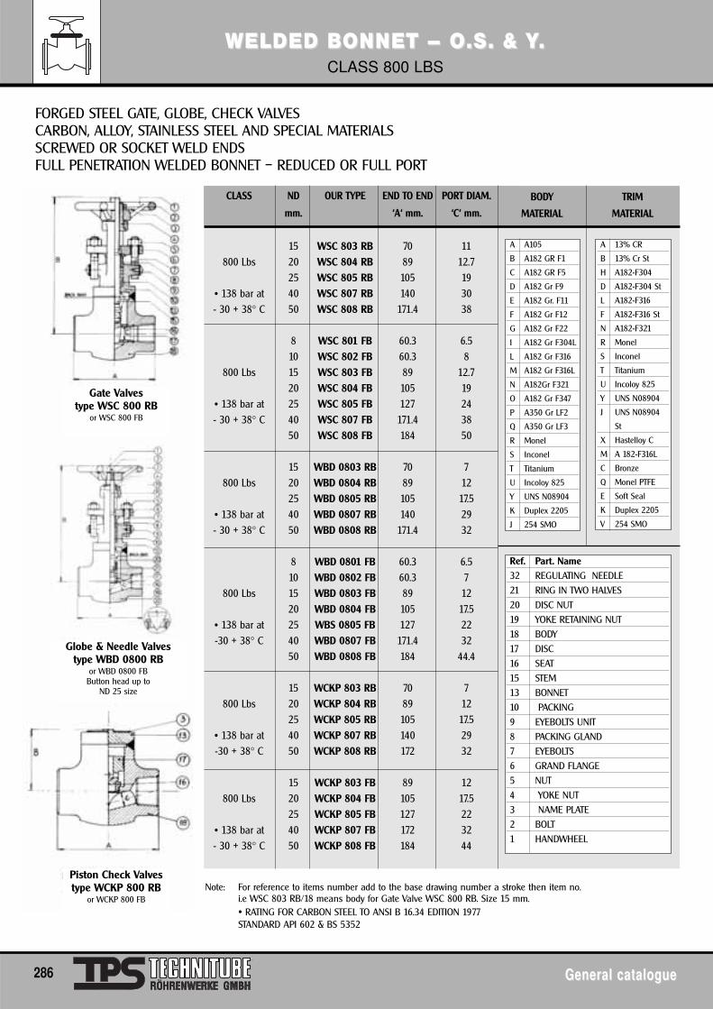
WELDED BWELDED BONNET – O.S. & YONNET – O.S. & Y. . CLASS 800 LBS
286 General catalogueGeneral catalogue
CLASS ND OUR TYPE END TO END PORT DIAM.
mm. ‘A‘ mm. ‘C‘ mm.
15 WSC 803 RB 70 11800 Lbs 20 WSC 804 RB 89 12.7
25 WSC 805 RB 105 19• 138 bar at 40 WSC 807 RB 140 30- 30 + 38° C 50 WSC 808 RB 171.4 38
8 WSC 801 FB 60.3 6.510 WSC 802 FB 60.3 8
800 Lbs 15 WSC 803 FB 89 12.720 WSC 804 FB 105 19
• 138 bar at 25 WSC 805 FB 127 24- 30 + 38° C 40 WSC 807 FB 171.4 38
50 WSC 808 FB 184 50
15 WBD 0803 RB 70 7800 Lbs 20 WBD 0804 RB 89 12
25 WBD 0805 RB 105 17.5• 138 bar at 40 WBD 0807 RB 140 29- 30 + 38° C 50 WBD 0808 RB 171.4 32
8 WBD 0801 FB 60.3 6.510 WBD 0802 FB 60.3 7
800 Lbs 15 WBD 0803 FB 89 1220 WBD 0804 FB 105 17.5
• 138 bar at 25 WBS 0805 FB 127 22-30 + 38° C 40 WBD 0807 FB 171.4 32
50 WBD 0808 FB 184 44.4
15 WCKP 803 RB 70 7800 Lbs 20 WCKP 804 RB 89 12
25 WCKP 805 RB 105 17.5• 138 bar at 40 WCKP 807 RB 140 29-30 + 38° C 50 WCKP 808 RB 172 32
15 WCKP 803 FB 89 12800 Lbs 20 WCKP 804 FB 105 17.5
25 WCKP 805 FB 127 22• 138 bar at 40 WCKP 807 FB 172 32- 30 + 38° C 50 WCKP 808 FB 184 44
FORGED STEEL GATE, GLOBE, CHECK VALVESCARBON, ALLOY, STAINLESS STEEL AND SPECIAL MATERIALSSCREWED OR SOCKET WELD ENDS FULL PENETRATION WELDED BONNET – REDUCED OR FULL PORT
Note: For reference to items number add to the base drawing number a stroke then item no.i.e WSC 803 RB/18 means body for Gate Valve WSC 800 RB. Size 15 mm.• RATING FOR CARBON STEEL TO ANSI B 16.34 EDITION 1977STANDARD API 602 & BS 5352
Gate Valvestype WSC 800 RB
or WSC 800 FB
Globe & Needle Valvestype WBD 0800 RB
or WBD 0800 FBButton head up to
ND 25 size
Piston Check Valvestype WCKP 800 RB
or WCKP 800 FB
A A105
B A182 GR F1
C A182 GR F5
D A182 Gr F9
E A182 Gr. F11
F A182 Gr F12
G A182 Gr F22
I A182 Gr F304L
L A182 Gr F316
M A182 Gr F316L
N A182Gr F321
O A182 Gr F347
P A350 Gr LF2
Q A350 Gr LF3
R Monel
S Inconel
T Titanium
U Incoloy 825
Y UNS N08904
K Duplex 2205
J 254 SMO
BODY
MATERIAL
TRIM
MATERIAL
Ref. Part. Name
32 REGULATING NEEDLE
21 RING IN TWO HALVES
20 DISC NUT
19 YOKE RETAINING NUT
18 BODY
17 DISC
16 SEAT
15 STEM
13 BONNET
10 PACKING
9 EYEBOLTS UNIT
8 PACKING GLAND
7 EYEBOLTS
6 GRAND FLANGE
5 NUT
4 YOKE NUT
3 NAME PLATE
2 BOLT
1 HANDWHEEL
A 13% CR
B 13% Cr St
H A182-F304
D A182-F304 St
L A182-F316
F A182-F316 St
N A182-F321
R Monel
S Inconel
T Titanium
U Incoloy 825
Y UNS N08904
J UNS N08904
St
X Hastelloy C
M A 182-F316L
C Bronze
Q Monel PTFE
E Soft Seal
K Duplex 2205
V 254 SMO
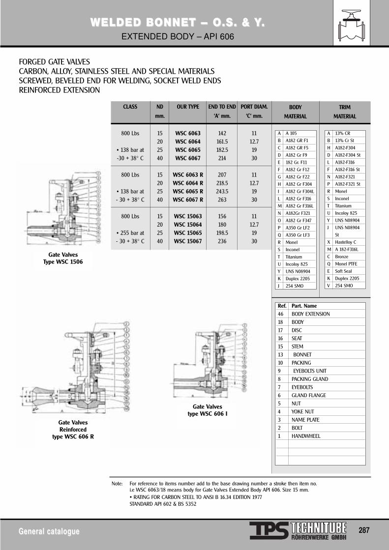
WELDED BWELDED BONNET – O.S. & YONNET – O.S. & Y. . EXTENDED BODY – API 606
General catalogueGeneral catalogue 287
CLASS ND OUR TYPE END TO END PORT DIAM.
mm. ‘A‘ mm. ‘C‘ mm.
800 Lbs 15 WSC 6063 142 1120 WSC 6064 161.5 12.7
• 138 bar at 25 WSC 6065 182.5 19-30 + 38° C 40 WSC 6067 214 30
800 Lbs 15 WSC 6063 R 207 1120 WSC 6064 R 218.5 12.7
• 138 bar at 25 WSC 6065 R 243.5 19- 30 + 38° C 40 WSC 6067 R 263 30
800 Lbs 15 WSC 15063 156 1120 WSC 15064 180 12.7
• 255 bar at 25 WSC 15065 198.5 19- 30 + 38° C 40 WSC 15067 236 30
FORGED GATE VALVESCARBON, ALLOY, STAINLESS STEEL AND SPECIAL MATERIALSSCREWED, BEVELED END FOR WELDING, SOCKET WELD ENDSREINFORCED EXTENSION
Note: For reference to items number add to the base drawing number a stroke then item no.i.e WSC 6063/18 means body for Gate Valves Extended Body API 606. Size 15 mm.• RATING FOR CARBON STEEL TO ANSI B 16.34 EDITION 1977STANDARD API 602 & BS 5352
Gate ValvesType WSC 1506
Gate ValvesReinforced
type WSC 606 R
Gate Valvestype WSC 606 I
A A 105
B A182 GR F1
C A182 GR F5
D A182 Gr F9
E 182 Gr. F11
F A182 Gr F12
G A182 Gr F22
H A182 Gr F304
I A182 Gr F304L
L A182 Gr F316
M A182 Gr F316L
N A182Gr F321
O A182 Gr F347
P A350 Gr LF2
Q A350 Gr LF3
R Monel
S Inconel
T Titanium
U Incoloy 825
Y UNS N08904
K Duplex 2205
J 254 SMO
BODY
MATERIAL
TRIM
MATERIAL
Ref. Part. Name
46 BODY EXTENSION
18 BODY
17 DISC
16 SEAT
15 STEM
13 BONNET
10 PACKING
9 EYEBOLTS UNIT
8 PACKING GLAND
7 EYEBOLTS
6 GLAND FLANGE
5 NUT
4 YOKE NUT
3 NAME PLATE
2 BOLT
1 HANDWHEEL
A 13% CR
B 13% Cr St
H A182-F304
D A182-F304 St
L A182-F316
F A182-F316 St
N A182-F321
P A182-F321 St
R Monel
S Inconel
T Titanium
U Incoloy 825
Y UNS N08904
J UNS N08904
St
X Hastelloy C
M A 182-F316L
C Bronze
Q Monel PTFE
E Soft Seal
K Duplex 2205
V 254 SMO
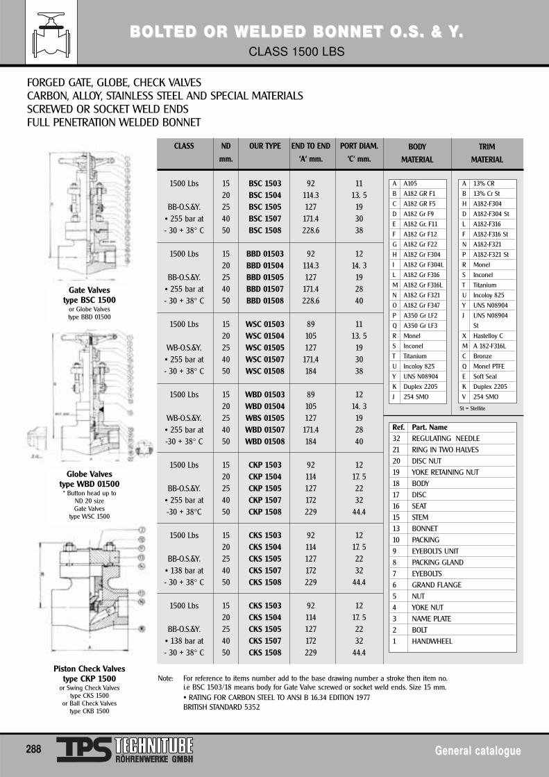
BBOLOLTED OR WELDED BTED OR WELDED BONNET O.S. & YONNET O.S. & Y. . CLASS 1500 LBS
288 General catalogueGeneral catalogue
CLASS ND OUR TYPE END TO END PORT DIAM.
mm. ‘A‘ mm. ‘C‘ mm.
1500 Lbs 15 BSC 1503 92 1120 BSC 1504 114.3 13. 5
BB-O.S.&Y. 25 BSC 1505 127 19• 255 bar at 40 BSC 1507 171.4 30- 30 + 38° C 50 BSC 1508 228.6 38
1500 Lbs 15 BBD 01503 92 1220 BBD 01504 114.3 14. 3
BB-O.S.&Y. 25 BBD 01505 127 19• 255 bar at 40 BBD 01507 171.4 28- 30 + 38° C 50 BBD 01508 228.6 40
1500 Lbs 15 WSC 01503 89 1120 WSC 01504 105 13. 5
WB-O.S.&Y. 25 WSC 01505 127 19• 255 bar at 40 WSC 01507 171,4 30- 30 + 38° C 50 WSC 01508 184 38
1500 Lbs 15 WBD 01503 89 1220 WBD 01504 105 14. 3
WB-O.S.&Y. 25 WBS 01505 127 19• 255 bar at 40 WBD 01507 171.4 28-30 + 38° C 50 WBD 01508 184 40
1500 Lbs 15 CKP 1503 92 1220 CKP 1504 114 17. 5
BB-O.S.&Y. 25 CKP 1505 127 22• 255 bar at 40 CKP 1507 172 32-30 + 38°C 50 CKP 1508 229 44.4
1500 Lbs 15 CKS 1503 92 1220 CKS 1504 114 17. 5
BB-O.S.&Y. 25 CKS 1505 127 22• 138 bar at 40 CKS 1507 172 32- 30 + 38° C 50 CKS 1508 229 44.4
1500 Lbs 15 CKS 1503 92 1220 CKS 1504 114 17. 5
BB-O.S.&Y. 25 CKS 1505 127 22• 138 bar at 40 CKS 1507 172 32- 30 + 38° C 50 CKS 1508 229 44.4
FORGED GATE, GLOBE, CHECK VALVESCARBON, ALLOY, STAINLESS STEEL AND SPECIAL MATERIALSSCREWED OR SOCKET WELD ENDS FULL PENETRATION WELDED BONNET
Note: For reference to items number add to the base drawing number a stroke then item no.i.e BSC 1503/18 means body for Gate Valve screwed or socket weld ends. Size 15 mm.• RATING FOR CARBON STEEL TO ANSI B 16.34 EDITION 1977BRITISH STANDARD 5352
Gate Valvestype BSC 1500
or Globe Valvestype BBD 01500
Globe Valvestype WBD 01500* Button head up to
ND 20 sizeGate Valves
type WSC 1500
Piston Check Valvestype CKP 1500
or Swing Check Valvestype CKS 1500
or Ball Check Valvestype CKB 1500
A A105
B A182 GR F1
C A182 GR F5
D A182 Gr F9
E A182 Gr. F11
F A182 Gr F12
G A182 Gr F22
H A182 Gr F304
I A182 Gr F304L
L A182 Gr F316
M A182 Gr F316L
N A182 Gr F321
O A182 Gr F347
P A350 Gr LF2
Q A350 Gr LF3
R Monel
S Inconel
T Titanium
U Incoloy 825
Y UNS N08904
K Duplex 2205
J 254 SMO
BODY
MATERIAL
TRIM
MATERIAL
Ref. Part. Name
32 REGULATING NEEDLE
21 RING IN TWO HALVES
20 DISC NUT
19 YOKE RETAINING NUT
18 BODY
17 DISC
16 SEAT
15 STEM
13 BONNET
10 PACKING
9 EYEBOLTS UNIT
8 PACKING GLAND
7 EYEBOLTS
6 GRAND FLANGE
5 NUT
4 YOKE NUT
3 NAME PLATE
2 BOLT
1 HANDWHEEL
A 13% CR
B 13% Cr St
H A182-F304
D A182-F304 St
L A182-F316
F A182-F316 St
N A182-F321
P A182-F321 St
R Monel
S Inconel
T Titanium
U Incoloy 825
Y UNS N08904
J UNS N08904
St
X Hastelloy C
M A 182-F316L
C Bronze
Q Monel PTFE
E Soft Seal
K Duplex 2205
V 254 SMO
St = Stellite
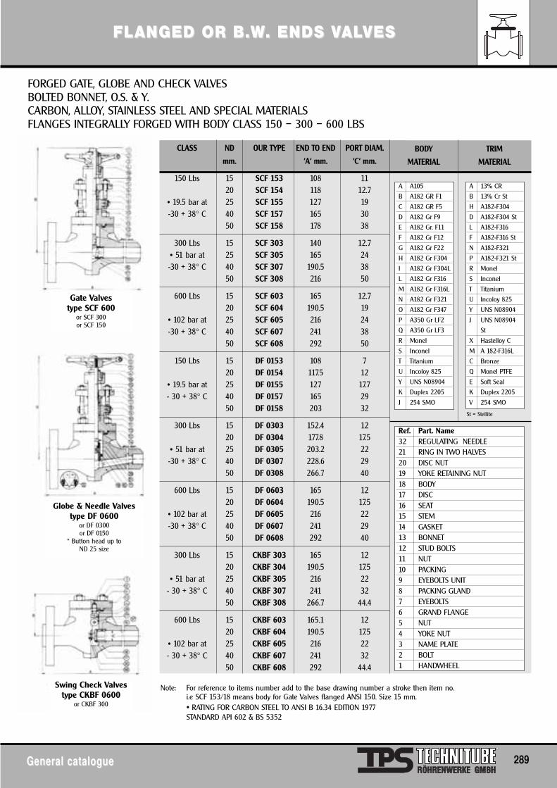
FLFLANANGED OR B.WGED OR B.W. ENDS V. ENDS VALALVESVES
General catalogueGeneral catalogue 289
CLASS ND OUR TYPE END TO END PORT DIAM.
mm. ‘A‘ mm. ‘C‘ mm.
150 Lbs 15 SCF 153 108 1120 SCF 154 118 12.7
• 19.5 bar at 25 SCF 155 127 19-30 + 38° C 40 SCF 157 165 30
50 SCF 158 178 38
300 Lbs 15 SCF 303 140 12.7• 51 bar at 25 SCF 305 165 24-30 + 38° C 40 SCF 307 190.5 38
50 SCF 308 216 50
600 Lbs 15 SCF 603 165 12.720 SCF 604 190.5 19
• 102 bar at 25 SCF 605 216 24-30 + 38° C 40 SCF 607 241 38
50 SCF 608 292 50
150 Lbs 15 DF 0153 108 720 DF 0154 117.5 12
• 19.5 bar at 25 DF 0155 127 17.7- 30 + 38° C 40 DF 0157 165 29
50 DF 0158 203 32
300 Lbs 15 DF 0303 152.4 1220 DF 0304 177.8 17.5
• 51 bar at 25 DF 0305 203.2 22-30 + 38° C 40 DF 0307 228.6 29
50 DF 0308 266.7 40
600 Lbs 15 DF 0603 165 1220 DF 0604 190.5 17.5
• 102 bar at 25 DF 0605 216 22-30 + 38° C 40 DF 0607 241 29
50 DF 0608 292 40
300 Lbs 15 CKBF 303 165 1220 CKBF 304 190.5 17.5
• 51 bar at 25 CKBF 305 216 22- 30 + 38° C 40 CKBF 307 241 32
50 CKBF 308 266.7 44.4
600 Lbs 15 CKBF 603 165.1 1220 CKBF 604 190.5 17.5
• 102 bar at 25 CKBF 605 216 22- 30 + 38° C 40 CKBF 607 241 32
50 CKBF 608 292 44.4
FORGED GATE, GLOBE AND CHECK VALVESBOLTED BONNET, O.S. & Y.CARBON, ALLOY, STAINLESS STEEL AND SPECIAL MATERIALSFLANGES INTEGRALLY FORGED WITH BODY CLASS 150 – 300 – 600 LBS
Note: For reference to items number add to the base drawing number a stroke then item no.i.e SCF 153/18 means body for Gate Valves flanged ANSI 150. Size 15 mm.• RATING FOR CARBON STEEL TO ANSI B 16.34 EDITION 1977STANDARD API 602 & BS 5352
Gate Valvestype SCF 600
or SCF 300or SCF 150
Globe & Needle Valvestype DF 0600
or DF 0300or DF 0150
* Button head up toND 25 size
Swing Check Valvestype CKBF 0600
or CKBF 300
A A105
B A182 GR F1
C A182 GR F5
D A182 Gr F9
E A182 Gr. F11
F A182 Gr F12
G A182 Gr F22
H A182 Gr F304
I A182 Gr F304L
L A182 Gr F316
M A182 Gr F316L
N A182 Gr F321
O A182 Gr F347
P A350 Gr LF2
Q A350 Gr LF3
R Monel
S Inconel
T Titanium
U Incoloy 825
Y UNS N08904
K Duplex 2205
J 254 SMO
BODY
MATERIAL
TRIM
MATERIAL
Ref. Part. Name32 REGULATING NEEDLE21 RING IN TWO HALVES20 DISC NUT19 YOKE RETAINING NUT18 BODY17 DISC16 SEAT15 STEM14 GASKET13 BONNET12 STUD BOLTS11 NUT10 PACKING9 EYEBOLTS UNIT8 PACKING GLAND7 EYEBOLTS6 GRAND FLANGE5 NUT4 YOKE NUT3 NAME PLATE2 BOLT1 HANDWHEEL
A 13% CR
B 13% Cr St
H A182-F304
D A182-F304 St
L A182-F316
F A182-F316 St
N A182-F321
P A182-F321 St
R Monel
S Inconel
T Titanium
U Incoloy 825
Y UNS N08904
J UNS N08904
St
X Hastelloy C
M A 182-F316L
C Bronze
Q Monel PTFE
E Soft Seal
K Duplex 2205
V 254 SMO
St = Stellite
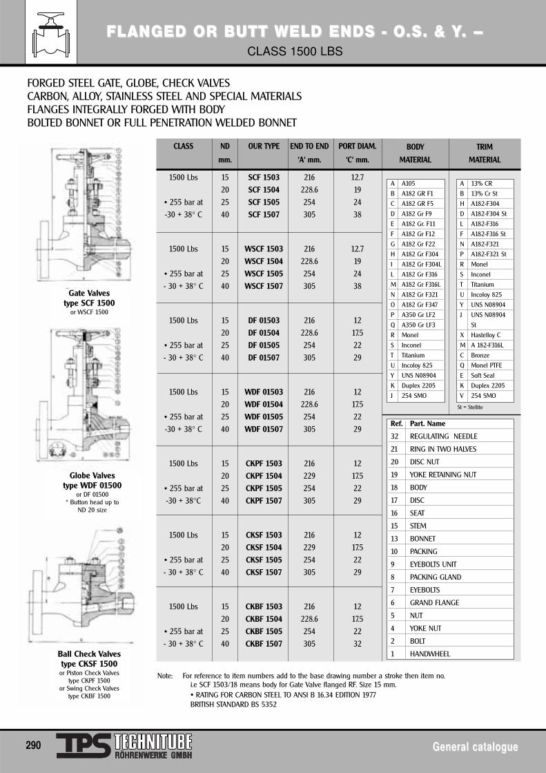
FLFLANANGED OR BUTT WELD ENDS - O.S. & YGED OR BUTT WELD ENDS - O.S. & Y. – . – CLASS 1500 LBS
290 General catalogueGeneral catalogue
CLASS ND OUR TYPE END TO END PORT DIAM.
mm. ‘A‘ mm. ‘C‘ mm.
1500 Lbs 15 SCF 1503 216 12.7
20 SCF 1504 228.6 19
• 255 bar at 25 SCF 1505 254 24
-30 + 38° C 40 SCF 1507 305 38
1500 Lbs 15 WSCF 1503 216 12.7
20 WSCF 1504 228.6 19
• 255 bar at 25 WSCF 1505 254 24
- 30 + 38° C 40 WSCF 1507 305 38
1500 Lbs 15 DF 01503 216 12
20 DF 01504 228.6 17.5
• 255 bar at 25 DF 01505 254 22
- 30 + 38° C 40 DF 01507 305 29
1500 Lbs 15 WDF 01503 216 12
20 WDF 01504 228.6 17.5
• 255 bar at 25 WDF 01505 254 22
-30 + 38° C 40 WDF 01507 305 29
1500 Lbs 15 CKPF 1503 216 12
20 CKPF 1504 229 17.5
• 255 bar at 25 CKPF 1505 254 22
-30 + 38°C 40 CKPF 1507 305 29
1500 Lbs 15 CKSF 1503 216 12
20 CKSF 1504 229 17.5
• 255 bar at 25 CKSF 1505 254 22
- 30 + 38° C 40 CKSF 1507 305 29
1500 Lbs 15 CKBF 1503 216 12
20 CKBF 1504 228.6 17.5
• 255 bar at 25 CKBF 1505 254 22
- 30 + 38° C 40 CKBF 1507 305 32
FORGED STEEL GATE, GLOBE, CHECK VALVESCARBON, ALLOY, STAINLESS STEEL AND SPECIAL MATERIALSFLANGES INTEGRALLY FORGED WITH BODYBOLTED BONNET OR FULL PENETRATION WELDED BONNET
Note: For reference to item numbers add to the base drawing number a stroke then item no.i.e SCF 1503/18 means body for Gate Valve flanged RF. Size 15 mm.• RATING FOR CARBON STEEL TO ANSI B 16.34 EDITION 1977BRITISH STANDARD BS 5352
Gate Valvestype SCF 1500
or WSCF 1500
Globe Valvestype WDF 01500
or DF 01500* Button head up to
ND 20 size
Ball Check Valvestype CKSF 1500or Piston Check Valves
type CKPF 1500or Swing Check Valves
type CKBF 1500
A A105
B A182 GR F1
C A182 GR F5
D A182 Gr F9
E A182 Gr. F11
F A182 Gr F12
G A182 Gr F22
H A182 Gr F304
I A182 Gr F304L
L A182 Gr F316
M A182 Gr F316L
N A182 Gr F321
O A182 Gr F347
P A350 Gr LF2
Q A350 Gr LF3
R Monel
S Inconel
T Titanium
U Incoloy 825
Y UNS N08904
K Duplex 2205
J 254 SMO
BODY
MATERIAL
TRIM
MATERIAL
Ref. Part. Name
32 REGULATING NEEDLE
21 RING IN TWO HALVES
20 DISC NUT
19 YOKE RETAINING NUT
18 BODY
17 DISC
16 SEAT
15 STEM
13 BONNET
10 PACKING
9 EYEBOLTS UNIT
8 PACKING GLAND
7 EYEBOLTS
6 GRAND FLANGE
5 NUT
4 YOKE NUT
2 BOLT
1 HANDWHEEL
A 13% CR
B 13% Cr St
H A182-F304
D A182-F304 St
L A182-F316
F A182-F316 St
N A182-F321
P A182-F321 St
R Monel
S Inconel
T Titanium
U Incoloy 825
Y UNS N08904
J UNS N08904
St
X Hastelloy C
M A 182-F316L
C Bronze
Q Monel PTFE
E Soft Seal
K Duplex 2205
V 254 SMO
St = Stellite
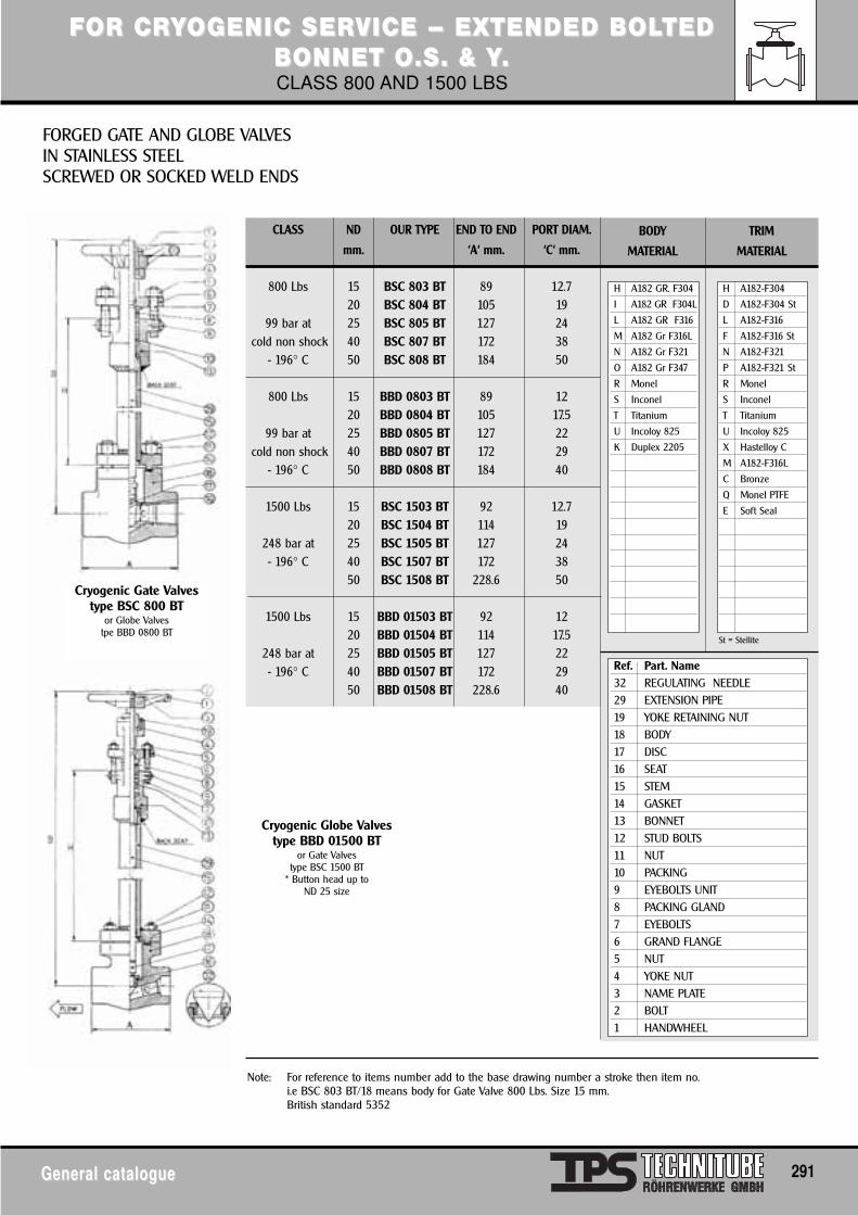
FFOR CROR CRYYOGENIC SERVICE – EXTENDED BOGENIC SERVICE – EXTENDED BOLOLTEDTEDBBONNET O.S. & YONNET O.S. & Y..CLASS 800 AND 1500 LBS
General catalogueGeneral catalogue 291
CLASS ND OUR TYPE END TO END PORT DIAM.
mm. ‘A‘ mm. ‘C‘ mm.
800 Lbs 15 BSC 803 BT 89 12.720 BSC 804 BT 105 19
99 bar at 25 BSC 805 BT 127 24cold non shock 40 BSC 807 BT 172 38
- 196° C 50 BSC 808 BT 184 50
800 Lbs 15 BBD 0803 BT 89 1220 BBD 0804 BT 105 17.5
99 bar at 25 BBD 0805 BT 127 22cold non shock 40 BBD 0807 BT 172 29
- 196° C 50 BBD 0808 BT 184 40
1500 Lbs 15 BSC 1503 BT 92 12.720 BSC 1504 BT 114 19
248 bar at 25 BSC 1505 BT 127 24- 196° C 40 BSC 1507 BT 172 38
50 BSC 1508 BT 228.6 50
1500 Lbs 15 BBD 01503 BT 92 1220 BBD 01504 BT 114 17.5
248 bar at 25 BBD 01505 BT 127 22- 196° C 40 BBD 01507 BT 172 29
50 BBD 01508 BT 228.6 40
FORGED GATE AND GLOBE VALVESIN STAINLESS STEELSCREWED OR SOCKED WELD ENDS
Note: For reference to items number add to the base drawing number a stroke then item no.i.e BSC 803 BT/18 means body for Gate Valve 800 Lbs. Size 15 mm.British standard 5352
Cryogenic Gate Valvestype BSC 800 BT
or Globe Valvestpe BBD 0800 BT
Cryogenic Globe Valvestype BBD 01500 BT
or Gate Valvestype BSC 1500 BT
* Button head up toND 25 size
H A182 GR. F304
I A182 GR F304L
L A182 GR F316
M A182 Gr F316L
N A182 Gr F321
O A182 Gr F347
R Monel
S Inconel
T Titanium
U Incoloy 825
K Duplex 2205
BODY
MATERIAL
TRIM
MATERIAL
Ref. Part. Name32 REGULATING NEEDLE29 EXTENSION PIPE19 YOKE RETAINING NUT18 BODY17 DISC16 SEAT15 STEM14 GASKET13 BONNET12 STUD BOLTS11 NUT10 PACKING9 EYEBOLTS UNIT8 PACKING GLAND7 EYEBOLTS6 GRAND FLANGE5 NUT4 YOKE NUT3 NAME PLATE2 BOLT1 HANDWHEEL
H A182-F304
D A182-F304 St
L A182-F316
F A182-F316 St
N A182-F321
P A182-F321 St
R Monel
S Inconel
T Titanium
U Incoloy 825
X Hastelloy C
M A182-F316L
C Bronze
Q Monel PTFE
E Soft Seal
St = Stellite
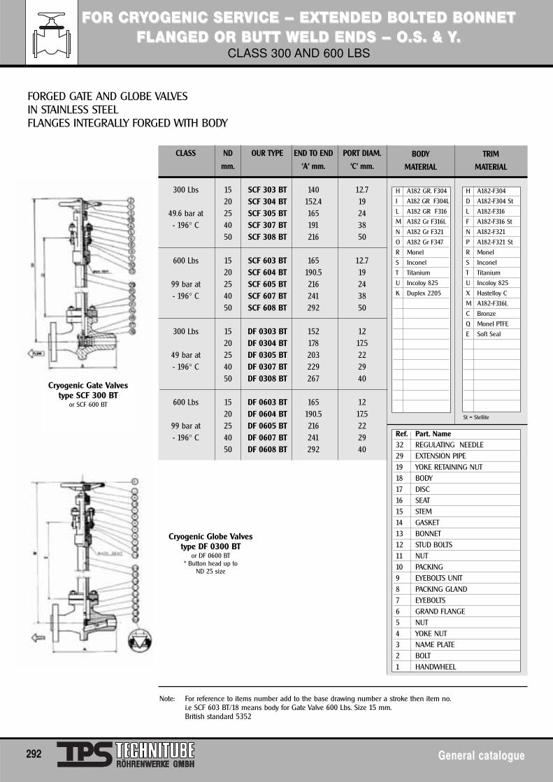
FFOR CROR CRYYOGENIC SERVICE – EXTENDED BOGENIC SERVICE – EXTENDED BOLOLTED BTED BONNETONNETFLFLANANGED OR BUTT WELD ENDS – O.S. & YGED OR BUTT WELD ENDS – O.S. & Y..
CLASS 300 AND 600 LBS
292 General catalogueGeneral catalogue
CLASS ND OUR TYPE END TO END PORT DIAM.
mm. ‘A‘ mm. ‘C‘ mm.
300 Lbs 15 SCF 303 BT 140 12.720 SCF 304 BT 152.4 19
49.6 bar at 25 SCF 305 BT 165 24- 196° C 40 SCF 307 BT 191 38
50 SCF 308 BT 216 50
600 Lbs 15 SCF 603 BT 165 12.720 SCF 604 BT 190.5 19
99 bar at 25 SCF 605 BT 216 24- 196° C 40 SCF 607 BT 241 38
50 SCF 608 BT 292 50
300 Lbs 15 DF 0303 BT 152 1220 DF 0304 BT 178 17.5
49 bar at 25 DF 0305 BT 203 22- 196° C 40 DF 0307 BT 229 29
50 DF 0308 BT 267 40
600 Lbs 15 DF 0603 BT 165 1220 DF 0604 BT 190.5 17.5
99 bar at 25 DF 0605 BT 216 22- 196° C 40 DF 0607 BT 241 29
50 DF 0608 BT 292 40
FORGED GATE AND GLOBE VALVESIN STAINLESS STEELFLANGES INTEGRALLY FORGED WITH BODY
Note: For reference to items number add to the base drawing number a stroke then item no.i.e SCF 603 BT/18 means body for Gate Valve 600 Lbs. Size 15 mm.British standard 5352
Cryogenic Gate Valvestype SCF 300 BT
or SCF 600 BT
Cryogenic Globe Valvestype DF 0300 BT
or DF 0600 BT* Button head up to
ND 25 size
H A182 GR. F304
I A182 GR F304L
L A182 GR F316
M A182 Gr F316L
N A182 Gr F321
O A182 Gr F347
R Monel
S Inconel
T Titanium
U Incoloy 825
K Duplex 2205
BODY
MATERIAL
TRIM
MATERIAL
Ref. Part. Name32 REGULATING NEEDLE29 EXTENSION PIPE19 YOKE RETAINING NUT18 BODY17 DISC16 SEAT15 STEM14 GASKET13 BONNET12 STUD BOLTS11 NUT10 PACKING9 EYEBOLTS UNIT8 PACKING GLAND7 EYEBOLTS6 GRAND FLANGE5 NUT4 YOKE NUT3 NAME PLATE2 BOLT1 HANDWHEEL
H A182-F304
D A182-F304 St
L A182-F316
F A182-F316 St
N A182-F321
P A182-F321 St
R Monel
S Inconel
T Titanium
U Incoloy 825
X Hastelloy C
M A182-F316L
C Bronze
Q Monel PTFE
E Soft Seal
St = Stellite
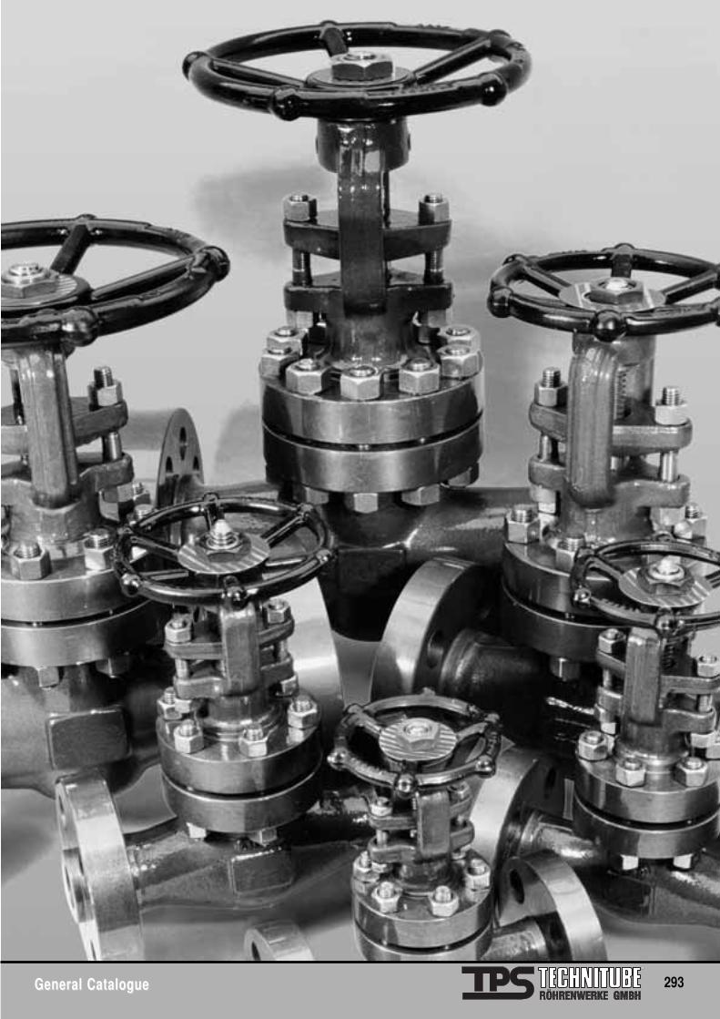
General CatalogueGeneral Catalogue 293
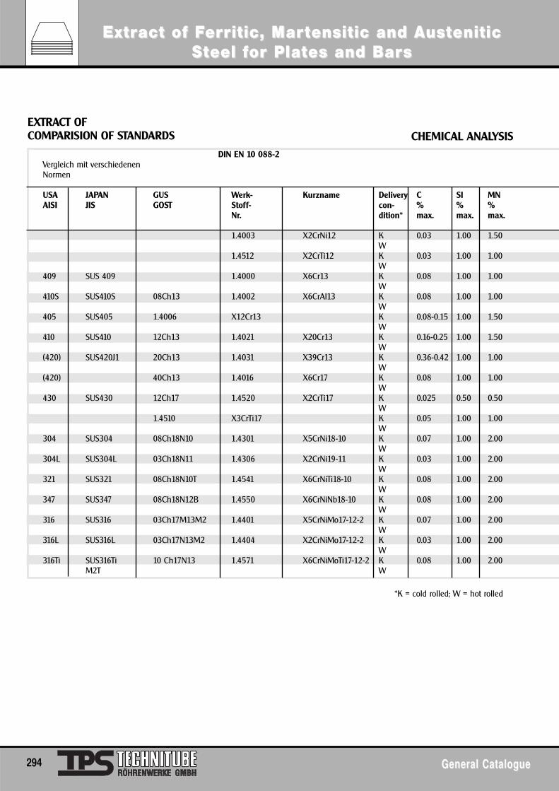
ExtrExtract of Fact of Fererrritic, Maritic, Marttensitic and Aensitic and AusustteniticeniticSStteel feel for Plator Plates and Bares and Barss
294 General CatalogueGeneral Catalogue
EXTRACT OFCOMPARISION OF STANDARDS CHEMICAL ANALYSIS
DIN EN 10 088-2Vergleich mit verschiedenen Normen
USA JAPAN GUS Werk- Kurzname Delivery C SI MNAISI JIS GOST Stoff- con- % % %
Nr. dition* max. max. max.
1.4003 X2CrNi12 K 0.03 1.00 1.50W
1.4512 X2CrTi12 K 0.03 1.00 1.00W
409 SUS 409 1.4000 X6Cr13 K 0.08 1.00 1.00W
410S SUS410S 08Ch13 1.4002 X6CrAl13 K 0.08 1.00 1.00W
405 SUS405 1.4006 X12Cr13 K 0.08-0.15 1.00 1.50W
410 SUS410 12Ch13 1.4021 X20Cr13 K 0.16-0.25 1.00 1.50W
(420) SUS420J1 20Ch13 1.4031 X39Cr13 K 0.36-0.42 1.00 1.00W
(420) 40Ch13 1.4016 X6Cr17 K 0.08 1.00 1.00W
430 SUS430 12Ch17 1.4520 X2CrTi17 K 0.025 0.50 0.50W
1.4510 X3CrTi17 K 0.05 1.00 1.00W
304 SUS304 08Ch18N10 1.4301 X5CrNi18-10 K 0.07 1.00 2.00W
304L SUS304L 03Ch18N11 1.4306 X2CrNi19-11 K 0.03 1.00 2.00W
321 SUS321 08Ch18N10T 1.4541 X6CrNiTi18-10 K 0.08 1.00 2.00W
347 SUS347 08Ch18N12B 1.4550 X6CrNiNb18-10 K 0.08 1.00 2.00W
316 SUS316 03Ch17M13M2 1.4401 X5CrNiMo17-12-2 K 0.07 1.00 2.00W
316L SUS316L 03Ch17N13M2 1.4404 X2CrNiMo17-12-2 K 0.03 1.00 2.00W
316Ti SUS316Ti 10 Ch17N13 1.4571 X6CrNiMoTi17-12-2 K 0.08 1.00 2.00M2T W
*K = cold rolled; W = hot rolled
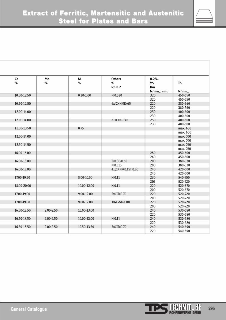
ExtrExtract of Fact of Fererrritic, Maritic, Marttensitic and Aensitic and AusustteniticeniticSStteel feel for Plator Plates and Bares and Barss
General CatalogueGeneral Catalogue 295
Cr Mo Ni Others 0.2%-% % % % YS TS
Rp 0.2 RmN/mm_ min. N/mm_
10.50-12.50 0.30-1.00 N:0.030 320 450-650320 450-650
10.50-12.50 6x(C+N)Ti0.65 220 380-560220 380-560
12.00-14.00 250 400-600230 400-600
12.00-14.00 Al:0.10-0.30 250 400-600230 400-600
11.50-13.50 0.75 max. 600max. 600
12.00-14.00 max. 700max. 700
12.50-14.50 max. 760max. 760
16.00-18.00 280 450-600260 450-600
16.00-18.00 Ti:0.30-0.60 200 380-530N:0.015 200 380-530
16.00-18.00 4x(C+N)+0.15Ti0.80 240 420-600240 420-600
17.00-19.50 8.00-10.50 N:0.11 230 540-750210 520-720
18.00-20.00 10.00-12.00 N:0.11 220 520-670200 520-670
17.00-19.00 9.00-12.00 5xC<Ti<0.70 220 520-720200 520-720
17.00-19.00 9.00-12.00 10xC<Nb<1.00 220 520-720200 520-720
16.50-18.50 2.00-2.50 10.00-13.00 240 530-680220 530-680
16.50-18.50 2.00-2.50 10.00-13.00 N:0.11 240 530-680220 530-680
16.50-18.50 2.00-2.50 10.50-13.50 5xC<Ti<0.70 240 540-690220 540-690
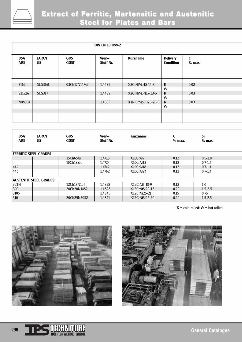
USA JAPAN GUS Werk- Kurzname C SiAISI JIS GOST Stoff-Nr. % max. % max.
FERRITIC STEEL GRADES15Ch6SJu 1.4713 X10CrAl7 0,12 0.5-1.010Ch13SJu 1.4724 X10CrAl13 0,12 0.7-1.4
442 1.4742 X10CrAl18 0,12 0.7-1.4446 1.4762 X10CrAl24 0,12 0.7-1.4
AUSTENTIC STEEL GRADES321H 12Ch18N10T 1.4878 X12CrNiTi18-9 0,12 1.0309 20Ch20N14S2 1.4828 X15CrNiSi20-12 0,20 1.5-2-5310S 1.4845 X12CrNi25-21 0,15 0.75310 20Ch25N20S2 1.4841 X15CrNiSi25-20 0,20 1.5-2.5
*K = cold rolled; W = hot rolled
296 General CatalogueGeneral Catalogue
ExtrExtract of Fact of Fererrritic, Maritic, Marttensitic and Aensitic and AusustteniticeniticSStteel feel for Plator Plates and Bares and Barss
DIN EN 10 088-2
USA JAPAN GUS Werk- Kurzname Delivery CAISI JIS GOST Stoff-Nr. Condition % max.
316L SUS316L 03Ch17N14M2 1.4435 X2CrNiMo18-14-3 K 0.02W
S31726 SUS317 1.4439 X2CrNiMoN17-13-5 K 0.03W
N08904 1.4539 X1NiCrMoCu25-20-5 K 0.03W
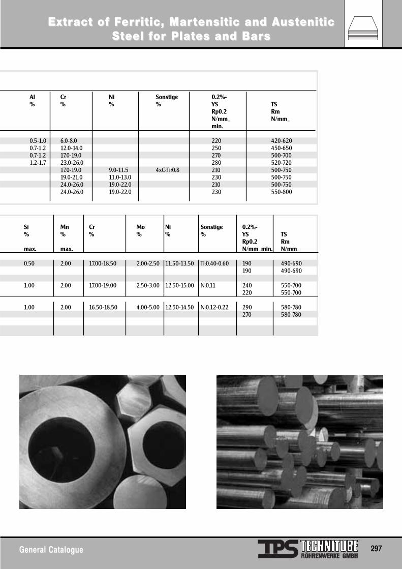
General CatalogueGeneral Catalogue 297
ExtrExtract of Fact of Fererrritic, Maritic, Marttensitic and Aensitic and AusustteniticeniticSStteel feel for Plator Plates and Bares and Barss
Al Cr Ni Sonstige 0.2%-% % % % YS TS
Rp0.2 RmN/mm_ N/mm_min.
0.5-1.0 6.0-8.0 220 420-6200.7-1.2 12.0-14.0 250 450-6500.7-1.2 17.0-19.0 270 500-7001.2-1.7 23.0-26.0 280 520-720
17.0-19.0 9.0-11.5 4xC<Ti<0.8 210 500-75019.0-21.0 11.0-13.0 230 500-75024.0-26.0 19.0-22.0 210 500-75024.0-26.0 19.0-22.0 230 550-800
Si Mn Cr Mo Ni Sonstige 0.2%-% % % % % % YS TS
Rp0.2 Rmmax. max. N/mm_min. N/mm_
0.50 2.00 17.00-18.50 2.00-2.50 11.50-13.50 Ti:0.40-0.60 190 490-690190 490-690
1.00 2.00 17.00-19.00 2.50-3.00 12.50-15.00 N:0,11 240 550-700220 550-700
1.00 2.00 16.50-18.50 4.00-5.00 12.50-14.50 N:0.12-0.22 290 580-780270 580-780
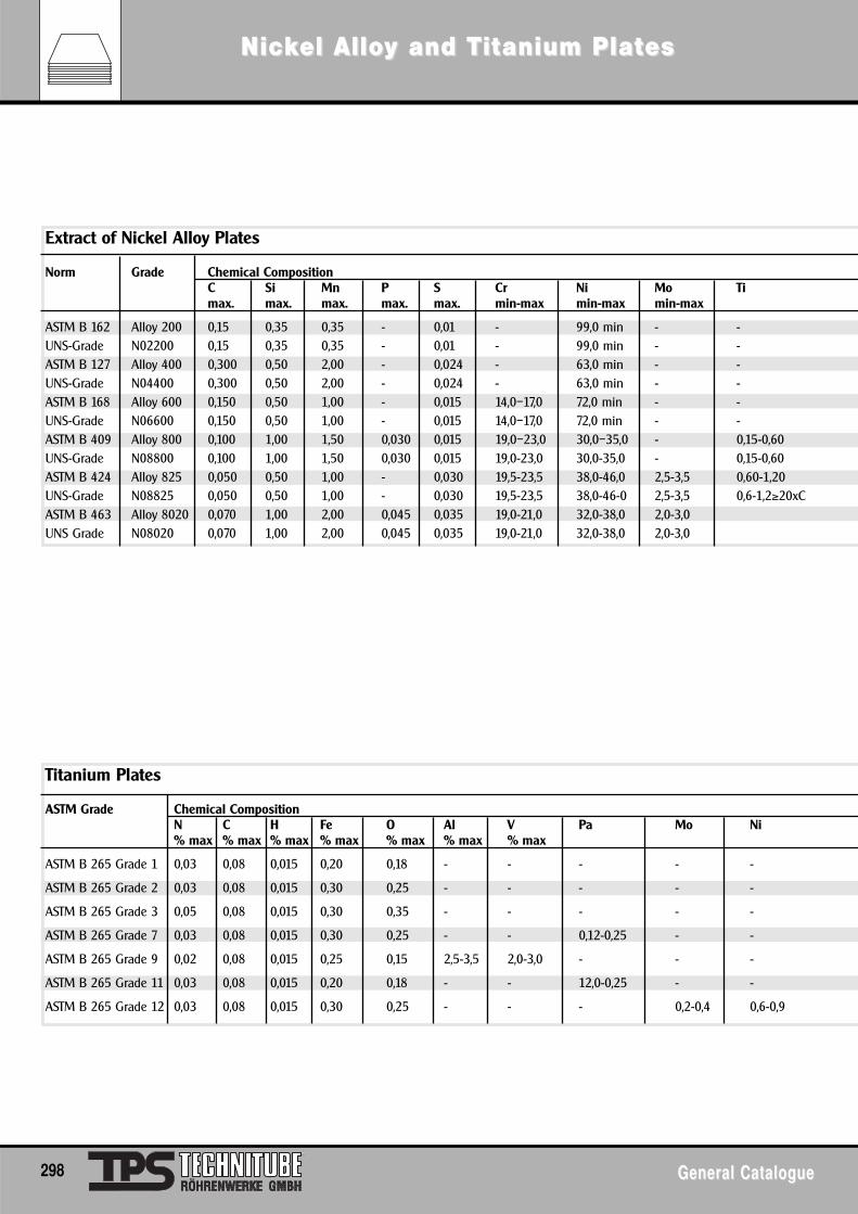
298 General CatalogueGeneral Catalogue
NicNickkel Alloel Alloy and Ty and Tititanium Platanium Plateses
Extract of Nickel Alloy Plates
Norm Grade Chemical CompositionC Si Mn P S Cr Ni Mo Timax. max. max. max. max. min-max min-max min-max
ASTM B 162 Alloy 200 0,15 0,35 0,35 - 0,01 - 99,0 min - -UNS-Grade N02200 0,15 0,35 0,35 - 0,01 - 99,0 min - -ASTM B 127 Alloy 400 0,300 0,50 2,00 - 0,024 - 63,0 min - -UNS-Grade N04400 0,300 0,50 2,00 - 0,024 - 63,0 min - -ASTM B 168 Alloy 600 0,150 0,50 1,00 - 0,015 14,0–17,0 72,0 min - -UNS-Grade N06600 0,150 0,50 1,00 - 0,015 14,0–17,0 72,0 min - -ASTM B 409 Alloy 800 0,100 1,00 1,50 0,030 0,015 19,0–23,0 30,0–35,0 - 0,15-0,60UNS-Grade N08800 0,100 1,00 1,50 0,030 0,015 19,0-23,0 30,0-35,0 - 0,15-0,60ASTM B 424 Alloy 825 0,050 0,50 1,00 - 0,030 19,5-23,5 38,0-46,0 2,5-3,5 0,60-1,20UNS-Grade N08825 0,050 0,50 1,00 - 0,030 19,5-23,5 38,0-46-0 2,5-3,5 0,6-1,2≥20xCASTM B 463 Alloy 8020 0,070 1,00 2,00 0,045 0,035 19,0-21,0 32,0-38,0 2,0-3,0UNS Grade N08020 0,070 1,00 2,00 0,045 0,035 19,0-21,0 32,0-38,0 2,0-3,0
Titanium Plates
ASTM Grade Chemical CompositionN C H Fe O Al V Pa Mo Ni% max % max % max % max % max % max % max
ASTM B 265 Grade 1 0,03 0,08 0,015 0,20 0,18 - - - - -
ASTM B 265 Grade 2 0,03 0,08 0,015 0,30 0,25 - - - - -
ASTM B 265 Grade 3 0,05 0,08 0,015 0,30 0,35 - - - - -
ASTM B 265 Grade 7 0,03 0,08 0,015 0,30 0,25 - - 0,12-0,25 - -
ASTM B 265 Grade 9 0,02 0,08 0,015 0,25 0,15 2,5-3,5 2,0-3,0 - - -
ASTM B 265 Grade 11 0,03 0,08 0,015 0,20 0,18 - - 12,0-0,25 - -
ASTM B 265 Grade 12 0,03 0,08 0,015 0,30 0,25 - - - 0,2-0,4 0,6-0,9
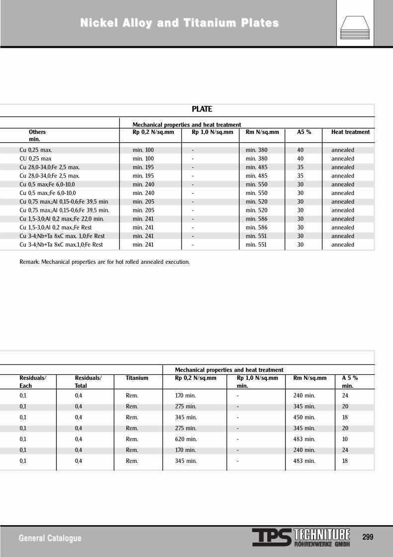
NicNickkel Alloel Alloy and Ty and Tititanium Platanium Plateses
General CatalogueGeneral Catalogue 299
PLATE
Mechanical properties and heat treatmentOthers Rp 0,2 N/sq.mm Rp 1,0 N/sq.mm Rm N/sq.mm A5 % Heat treatmentmin.
Cu 0,25 max. min. 100 - min. 380 40 annealedCU 0,25 max min. 100 - min. 380 40 annealedCu 28,0-34,0;Fe 2,5 max. min. 195 - min. 485 35 annealedCu 28,0-34,0;Fe 2,5 max. min. 195 - min. 485 35 annealedCu 0,5 max;Fe 6,0-10,0 min. 240 - min. 550 30 annealedCu 0,5 max.;Fe 6,0-10,0 min. 240 - min. 550 30 annealedCu 0,75 max.;Al 0,15-0,6;Fe 39,5 min min. 205 - min. 520 30 annealedCu 0,75 max.;Al 0,15-0,6;Fe 39,5 min. min. 205 - min. 520 30 annealedCu 1,5-3,0;Al 0,2 max.;Fe 22,0 min. min. 241 - min. 586 30 annealedCu 1,5-3,0;Al 0,2 max.;Fe Rest min. 241 - min. 586 30 annealedCu 3-4;Nb+Ta 8xC max. 1,0;Fe Rest min. 241 - min. 551 30 annealedCu 3-4;Nb+Ta 8xC max.1,0;Fe Rest min. 241 - min. 551 30 annealed
Remark: Mechanical properties are for hot rolled annealed execution.
Mechanical properties and heat treatmentResiduals/ Residuals/ Titanium Rp 0,2 N/sq.mm Rp 1,0 N/sq.mm Rm N/sq.mm A 5 %Each Total min. min.
0,1 0,4 Rem. 170 min. - 240 min. 24
0,1 0,4 Rem. 275 min. - 345 min. 20
0,1 0,4 Rem. 345 min. - 450 min. 18
0,1 0,4 Rem. 275 min. - 345 min. 20
0,1 0,4 Rem. 620 min. - 483 min. 10
0,1 0,4 Rem. 170 min. - 240 min. 24
0,1 0,4 Rem. 345 min. - 483 min. 18
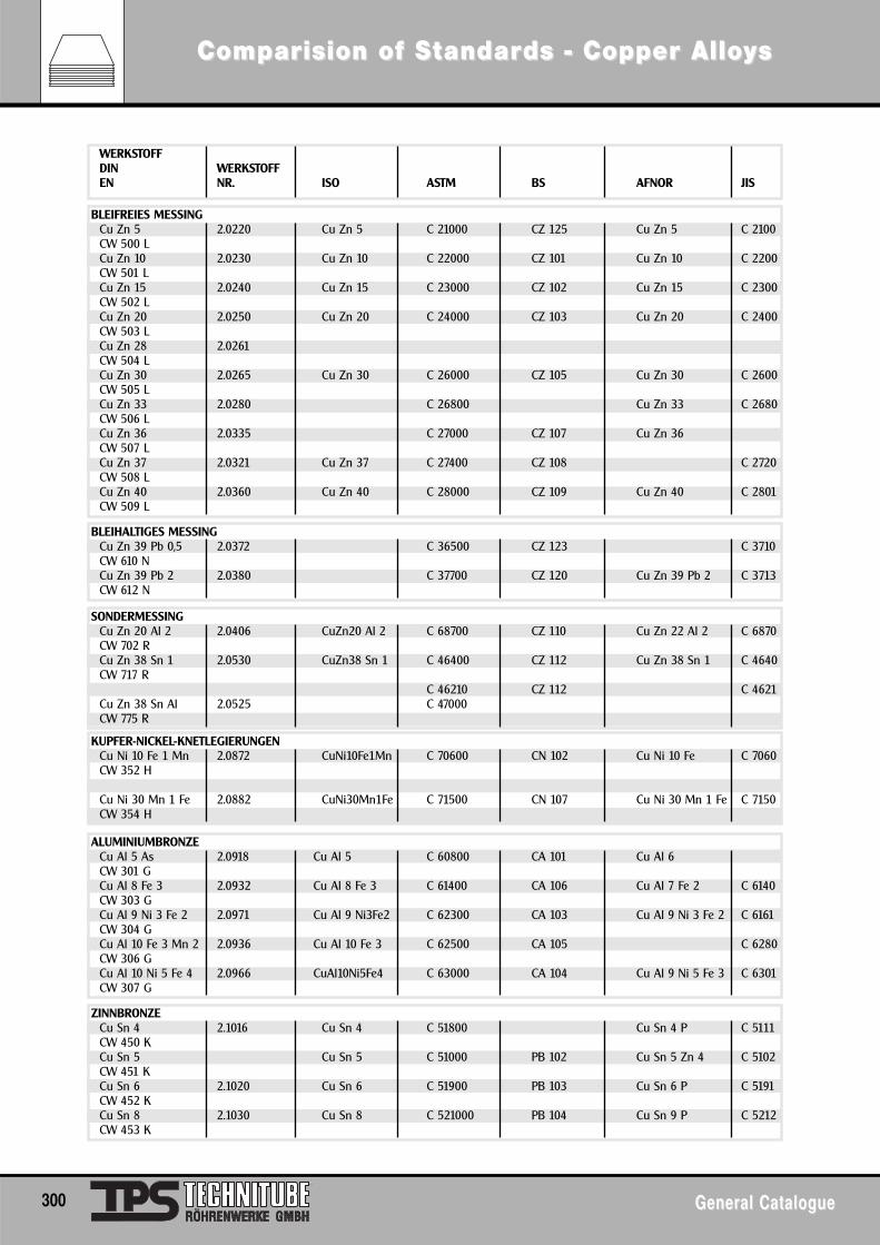
BLEIFREIES MESSINGCu Zn 5 2.0220 Cu Zn 5 C 21000 CZ 125 Cu Zn 5 C 2100CW 500 LCu Zn 10 2.0230 Cu Zn 10 C 22000 CZ 101 Cu Zn 10 C 2200CW 501 LCu Zn 15 2.0240 Cu Zn 15 C 23000 CZ 102 Cu Zn 15 C 2300CW 502 LCu Zn 20 2.0250 Cu Zn 20 C 24000 CZ 103 Cu Zn 20 C 2400CW 503 LCu Zn 28 2.0261CW 504 LCu Zn 30 2.0265 Cu Zn 30 C 26000 CZ 105 Cu Zn 30 C 2600CW 505 LCu Zn 33 2.0280 C 26800 Cu Zn 33 C 2680CW 506 LCu Zn 36 2.0335 C 27000 CZ 107 Cu Zn 36CW 507 LCu Zn 37 2.0321 Cu Zn 37 C 27400 CZ 108 C 2720CW 508 LCu Zn 40 2.0360 Cu Zn 40 C 28000 CZ 109 Cu Zn 40 C 2801CW 509 L
BLEIHALTIGES MESSINGCu Zn 39 Pb 0,5 2.0372 C 36500 CZ 123 C 3710CW 610 NCu Zn 39 Pb 2 2.0380 C 37700 CZ 120 Cu Zn 39 Pb 2 C 3713CW 612 N
SONDERMESSINGCu Zn 20 Al 2 2.0406 CuZn20 Al 2 C 68700 CZ 110 Cu Zn 22 Al 2 C 6870CW 702 RCu Zn 38 Sn 1 2.0530 CuZn38 Sn 1 C 46400 CZ 112 Cu Zn 38 Sn 1 C 4640CW 717 R
C 46210 CZ 112 C 4621Cu Zn 38 Sn Al 2.0525 C 47000CW 775 R
KUPFER-NICKEL-KNETLEGIERUNGENCu Ni 10 Fe 1 Mn 2.0872 CuNi10Fe1Mn C 70600 CN 102 Cu Ni 10 Fe C 7060CW 352 H
Cu Ni 30 Mn 1 Fe 2.0882 CuNi30Mn1Fe C 71500 CN 107 Cu Ni 30 Mn 1 Fe C 7150CW 354 H
ALUMINIUMBRONZECu Al 5 As 2.0918 Cu Al 5 C 60800 CA 101 Cu Al 6CW 301 GCu Al 8 Fe 3 2.0932 Cu Al 8 Fe 3 C 61400 CA 106 Cu Al 7 Fe 2 C 6140CW 303 GCu Al 9 Ni 3 Fe 2 2.0971 Cu Al 9 Ni3Fe2 C 62300 CA 103 Cu Al 9 Ni 3 Fe 2 C 6161CW 304 GCu Al 10 Fe 3 Mn 2 2.0936 Cu Al 10 Fe 3 C 62500 CA 105 C 6280CW 306 GCu Al 10 Ni 5 Fe 4 2.0966 CuAl10Ni5Fe4 C 63000 CA 104 Cu Al 9 Ni 5 Fe 3 C 6301CW 307 G
ZINNBRONZECu Sn 4 2.1016 Cu Sn 4 C 51800 Cu Sn 4 P C 5111CW 450 KCu Sn 5 Cu Sn 5 C 51000 PB 102 Cu Sn 5 Zn 4 C 5102CW 451 KCu Sn 6 2.1020 Cu Sn 6 C 51900 PB 103 Cu Sn 6 P C 5191CW 452 KCu Sn 8 2.1030 Cu Sn 8 C 521000 PB 104 Cu Sn 9 P C 5212CW 453 K
WERKSTOFFDIN WERKSTOFFEN NR. ISO ASTM BS AFNOR JIS
300 General CatalogueGeneral Catalogue
ComComparparision of Sision of Sttandarandards - Copper Allods - Copper Alloyyss
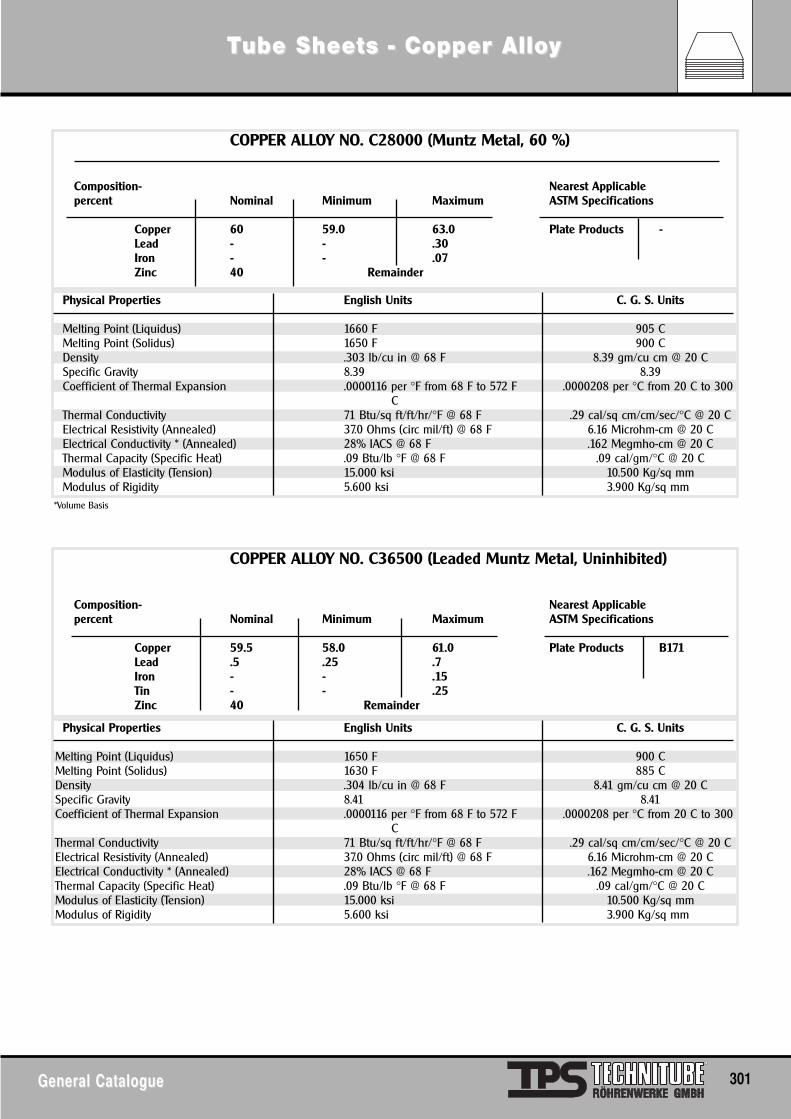
General CatalogueGeneral Catalogue 301
TTube Sheeube Sheets - Copper Allots - Copper Alloyy
COPPER ALLOY NO. C28000 (Muntz Metal, 60 %)
Composition- Nearest Applicable percent Nominal Minimum Maximum ASTM Specifications
Copper 60 59.0 63.0 Plate Products -Lead - - .30Iron - - .07Zinc 40 Remainder
Physical Properties English Units C. G. S. Units
Melting Point (Liquidus) 1660 F 905 CMelting Point (Solidus) 1650 F 900 CDensity .303 lb/cu in @ 68 F 8.39 gm/cu cm @ 20 CSpecific Gravity 8.39 8.39Coefficient of Thermal Expansion .0000116 per °F from 68 F to 572 F .0000208 per °C from 20 C to 300
CThermal Conductivity 71 Btu/sq ft/ft/hr/°F @ 68 F .29 cal/sq cm/cm/sec/°C @ 20 CElectrical Resistivity (Annealed) 37.0 Ohms (circ mil/ft) @ 68 F 6.16 Microhm-cm @ 20 CElectrical Conductivity * (Annealed) 28% IACS @ 68 F .162 Megmho-cm @ 20 CThermal Capacity (Specific Heat) .09 Btu/lb °F @ 68 F .09 cal/gm/°C @ 20 CModulus of Elasticity (Tension) 15.000 ksi 10.500 Kg/sq mmModulus of Rigidity 5.600 ksi 3.900 Kg/sq mm
*Volume Basis
COPPER ALLOY NO. C36500 (Leaded Muntz Metal, Uninhibited)
Composition- Nearest Applicable percent Nominal Minimum Maximum ASTM Specifications
Copper 59.5 58.0 61.0 Plate Products B171Lead .5 .25 .7Iron - - .15Tin - - .25Zinc 40 Remainder
Physical Properties English Units C. G. S. Units
Melting Point (Liquidus) 1650 F 900 CMelting Point (Solidus) 1630 F 885 CDensity .304 lb/cu in @ 68 F 8.41 gm/cu cm @ 20 CSpecific Gravity 8.41 8.41Coefficient of Thermal Expansion .0000116 per °F from 68 F to 572 F .0000208 per °C from 20 C to 300
CThermal Conductivity 71 Btu/sq ft/ft/hr/°F @ 68 F .29 cal/sq cm/cm/sec/°C @ 20 CElectrical Resistivity (Annealed) 37.0 Ohms (circ mil/ft) @ 68 F 6.16 Microhm-cm @ 20 CElectrical Conductivity * (Annealed) 28% IACS @ 68 F .162 Megmho-cm @ 20 CThermal Capacity (Specific Heat) .09 Btu/lb °F @ 68 F .09 cal/gm/°C @ 20 CModulus of Elasticity (Tension) 15.000 ksi 10.500 Kg/sq mmModulus of Rigidity 5.600 ksi 3.900 Kg/sq mm
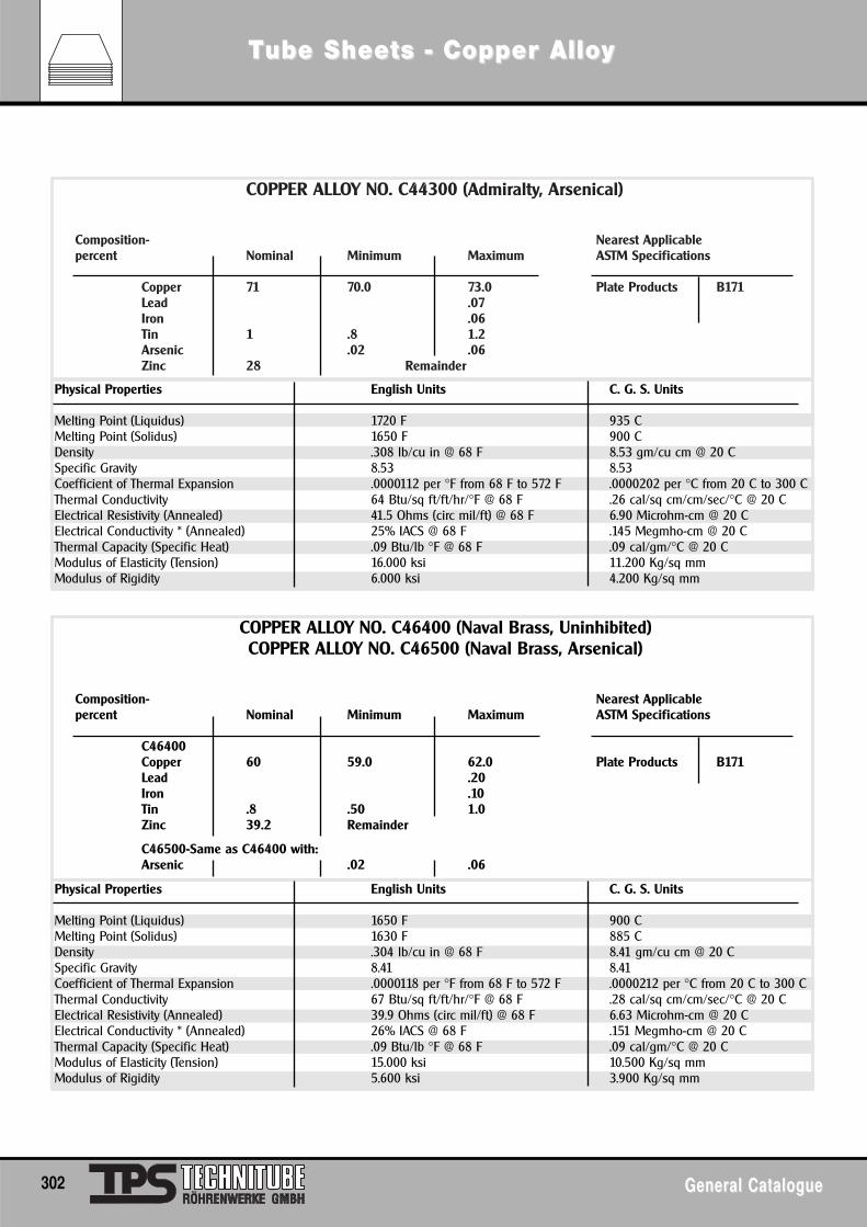
COPPER ALLOY NO. C44300 (Admiralty, Arsenical)
Composition- Nearest Applicable percent Nominal Minimum Maximum ASTM Specifications
Copper 71 70.0 73.0 Plate Products B171Lead .07Iron .06Tin 1 .8 1.2Arsenic .02 .06Zinc 28 Remainder
Physical Properties English Units C. G. S. Units
Melting Point (Liquidus) 1720 F 935 CMelting Point (Solidus) 1650 F 900 CDensity .308 lb/cu in @ 68 F 8.53 gm/cu cm @ 20 CSpecific Gravity 8.53 8.53Coefficient of Thermal Expansion .0000112 per °F from 68 F to 572 F .0000202 per °C from 20 C to 300 CThermal Conductivity 64 Btu/sq ft/ft/hr/°F @ 68 F .26 cal/sq cm/cm/sec/°C @ 20 CElectrical Resistivity (Annealed) 41.5 Ohms (circ mil/ft) @ 68 F 6.90 Microhm-cm @ 20 CElectrical Conductivity * (Annealed) 25% IACS @ 68 F .145 Megmho-cm @ 20 CThermal Capacity (Specific Heat) .09 Btu/lb °F @ 68 F .09 cal/gm/°C @ 20 CModulus of Elasticity (Tension) 16.000 ksi 11.200 Kg/sq mmModulus of Rigidity 6.000 ksi 4.200 Kg/sq mm
COPPER ALLOY NO. C46400 (Naval Brass, Uninhibited)COPPER ALLOY NO. C46500 (Naval Brass, Arsenical)
Composition- Nearest Applicable percent Nominal Minimum Maximum ASTM Specifications
C46400Copper 60 59.0 62.0 Plate Products B171Lead .20Iron .10Tin .8 .50 1.0Zinc 39.2 Remainder
C46500-Same as C46400 with:Arsenic .02 .06
Physical Properties English Units C. G. S. Units
Melting Point (Liquidus) 1650 F 900 CMelting Point (Solidus) 1630 F 885 CDensity .304 lb/cu in @ 68 F 8.41 gm/cu cm @ 20 CSpecific Gravity 8.41 8.41Coefficient of Thermal Expansion .0000118 per °F from 68 F to 572 F .0000212 per °C from 20 C to 300 CThermal Conductivity 67 Btu/sq ft/ft/hr/°F @ 68 F .28 cal/sq cm/cm/sec/°C @ 20 CElectrical Resistivity (Annealed) 39.9 Ohms (circ mil/ft) @ 68 F 6.63 Microhm-cm @ 20 CElectrical Conductivity * (Annealed) 26% IACS @ 68 F .151 Megmho-cm @ 20 CThermal Capacity (Specific Heat) .09 Btu/lb °F @ 68 F .09 cal/gm/°C @ 20 CModulus of Elasticity (Tension) 15.000 ksi 10.500 Kg/sq mmModulus of Rigidity 5.600 ksi 3.900 Kg/sq mm
302 General CatalogueGeneral Catalogue
TTube Sheeube Sheets - Copper Allots - Copper Alloyy
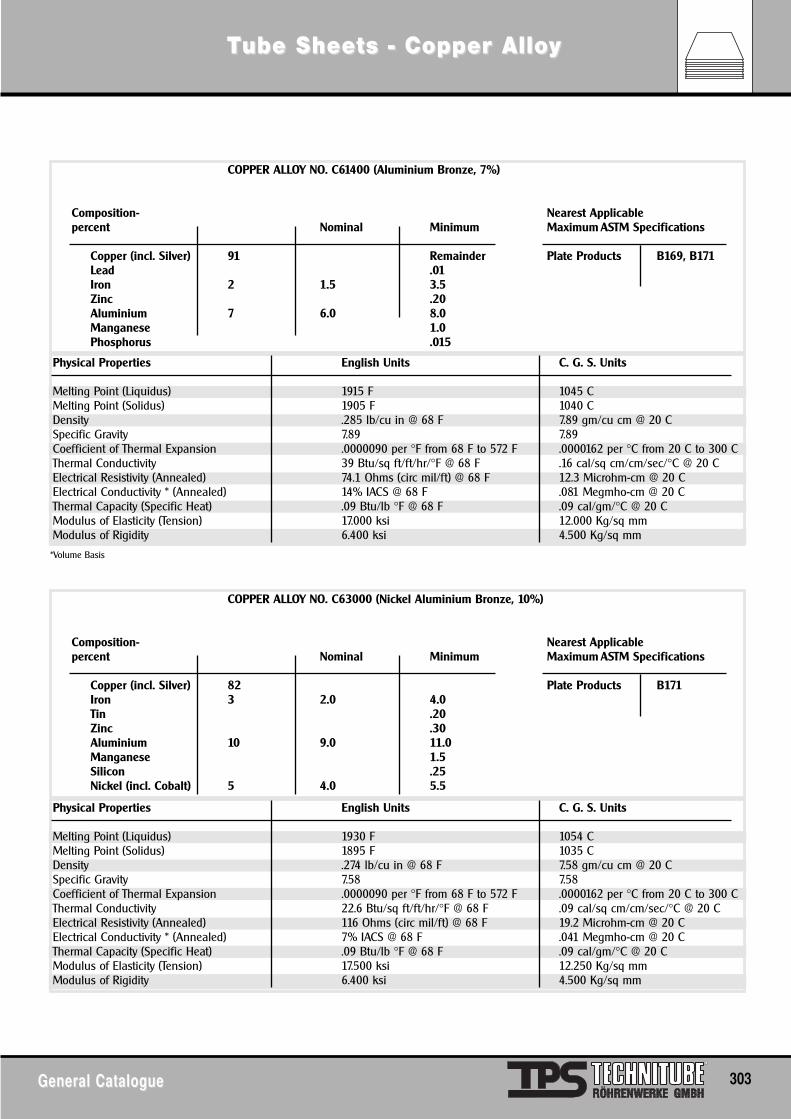
General CatalogueGeneral Catalogue 303
TTube Sheeube Sheets - Copper Allots - Copper Alloyy
COPPER ALLOY NO. C61400 (Aluminium Bronze, 7%)
Composition- Nearest Applicable percent Nominal Minimum Maximum ASTM Specifications
Copper (incl. Silver) 91 Remainder Plate Products B169, B171Lead .01Iron 2 1.5 3.5Zinc .20Aluminium 7 6.0 8.0Manganese 1.0Phosphorus .015
Physical Properties English Units C. G. S. Units
Melting Point (Liquidus) 1915 F 1045 CMelting Point (Solidus) 1905 F 1040 CDensity .285 lb/cu in @ 68 F 7.89 gm/cu cm @ 20 CSpecific Gravity 7.89 7.89Coefficient of Thermal Expansion .0000090 per °F from 68 F to 572 F .0000162 per °C from 20 C to 300 CThermal Conductivity 39 Btu/sq ft/ft/hr/°F @ 68 F .16 cal/sq cm/cm/sec/°C @ 20 CElectrical Resistivity (Annealed) 74.1 Ohms (circ mil/ft) @ 68 F 12.3 Microhm-cm @ 20 CElectrical Conductivity * (Annealed) 14% IACS @ 68 F .081 Megmho-cm @ 20 CThermal Capacity (Specific Heat) .09 Btu/lb °F @ 68 F .09 cal/gm/°C @ 20 CModulus of Elasticity (Tension) 17.000 ksi 12.000 Kg/sq mmModulus of Rigidity 6.400 ksi 4.500 Kg/sq mm
COPPER ALLOY NO. C63000 (Nickel Aluminium Bronze, 10%)
Composition- Nearest Applicable percent Nominal Minimum Maximum ASTM Specifications
Copper (incl. Silver) 82 Plate Products B171Iron 3 2.0 4.0Tin .20Zinc .30Aluminium 10 9.0 11.0Manganese 1.5Silicon .25Nickel (incl. Cobalt) 5 4.0 5.5
Physical Properties English Units C. G. S. Units
Melting Point (Liquidus) 1930 F 1054 CMelting Point (Solidus) 1895 F 1035 CDensity .274 lb/cu in @ 68 F 7.58 gm/cu cm @ 20 CSpecific Gravity 7.58 7.58Coefficient of Thermal Expansion .0000090 per °F from 68 F to 572 F .0000162 per °C from 20 C to 300 CThermal Conductivity 22.6 Btu/sq ft/ft/hr/°F @ 68 F .09 cal/sq cm/cm/sec/°C @ 20 CElectrical Resistivity (Annealed) 116 Ohms (circ mil/ft) @ 68 F 19.2 Microhm-cm @ 20 CElectrical Conductivity * (Annealed) 7% IACS @ 68 F .041 Megmho-cm @ 20 CThermal Capacity (Specific Heat) .09 Btu/lb °F @ 68 F .09 cal/gm/°C @ 20 CModulus of Elasticity (Tension) 17.500 ksi 12.250 Kg/sq mmModulus of Rigidity 6.400 ksi 4.500 Kg/sq mm
*Volume Basis
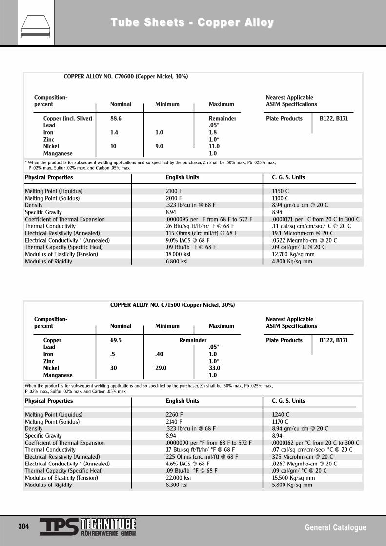
COPPER ALLOY NO. C70600 (Copper Nickel, 10%)
Composition- Nearest Applicable percent Nominal Minimum Maximum ASTM Specifications
Copper (incl. Silver) 88.6 Remainder Plate Products B122, B171Lead .05*Iron 1.4 1.0 1.8Zinc 1.0*Nickel 10 9.0 11.0Manganese 1.0
Physical Properties English Units C. G. S. Units
Melting Point (Liquidus) 2100 F 1150 CMelting Point (Solidus) 2010 F 1100 CDensity .323 lb/cu in @ 68 F 8.94 gm/cu cm @ 20 CSpecific Gravity 8.94 8.94Coefficient of Thermal Expansion .0000095 per F from 68 F to 572 F .0000171 per C from 20 C to 300 CThermal Conductivity 26 Btu/sq ft/ft/hr/ F @ 68 F .11 cal/sq cm/cm/sec/ C @ 20 CElectrical Resistivity (Annealed) 115 Ohms (circ mil/ft) @ 68 F 19.1 Microhm-cm @ 20 CElectrical Conductivity * (Annealed) 9.0% IACS @ 68 F .0522 Megmho-cm @ 20 CThermal Capacity (Specific Heat) .09 Btu/lb F @ 68 F .09 cal/gm/ C @ 20 CModulus of Elasticity (Tension) 18.000 ksi 12.700 Kg/sq mmModulus of Rigidity 6.800 ksi 4.800 Kg/sq mm
* When the product is for subsequent welding applications and so specified by the purchaser, Zn shall be .50% max., Pb .025% max.,P .02% max., Sulfur .02% max. and Carbon .05% max.
Physical Properties English Units C. G. S. Units
Melting Point (Liquidus) 2260 F 1240 CMelting Point (Solidus) 2140 F 1170 CDensity .323 lb/cu in @ 68 F 8.94 gm/cu cm @ 20 CSpecific Gravity 8.94 8.94Coefficient of Thermal Expansion .0000090 per °F from 68 F to 572 F .0000162 per °C from 20 C to 300 CThermal Conductivity 17 Btu/sq ft/ft/hr/ °F @ 68 F .07 cal/sq cm/cm/sec/ °C @ 20 CElectrical Resistivity (Annealed) 225 Ohms (circ mil/ft) @ 68 F 37.5 Microhm-cm @ 20 CElectrical Conductivity * (Annealed) 4.6% IACS @ 68 F .0267 Megmho-cm @ 20 CThermal Capacity (Specific Heat) .09 Btu/lb °F @ 68 F .09 cal/gm/ °C @ 20 CModulus of Elasticity (Tension) 22.000 ksi 15.500 Kg/sq mmModulus of Rigidity 8.300 ksi 5.800 Kg/sq mm
When the product is for subsequent welding applications and so specified by the purchaser, Zn shall be .50% max., Pb .025% max.,P .02% max., Sulfur .02% max. and Carbon .05% max.
COPPER ALLOY NO. C71500 (Copper Nickel, 30%)
Composition- Nearest Applicable percent Nominal Minimum Maximum ASTM Specifications
Copper 69.5 Remainder Plate Products B122, B171Lead .05*Iron .5 .40 1.0Zinc 1.0*Nickel 30 29.0 33.0Manganese 1.0
304 General CatalogueGeneral Catalogue
TTube Sheeube Sheets - Copper Allots - Copper Alloyy
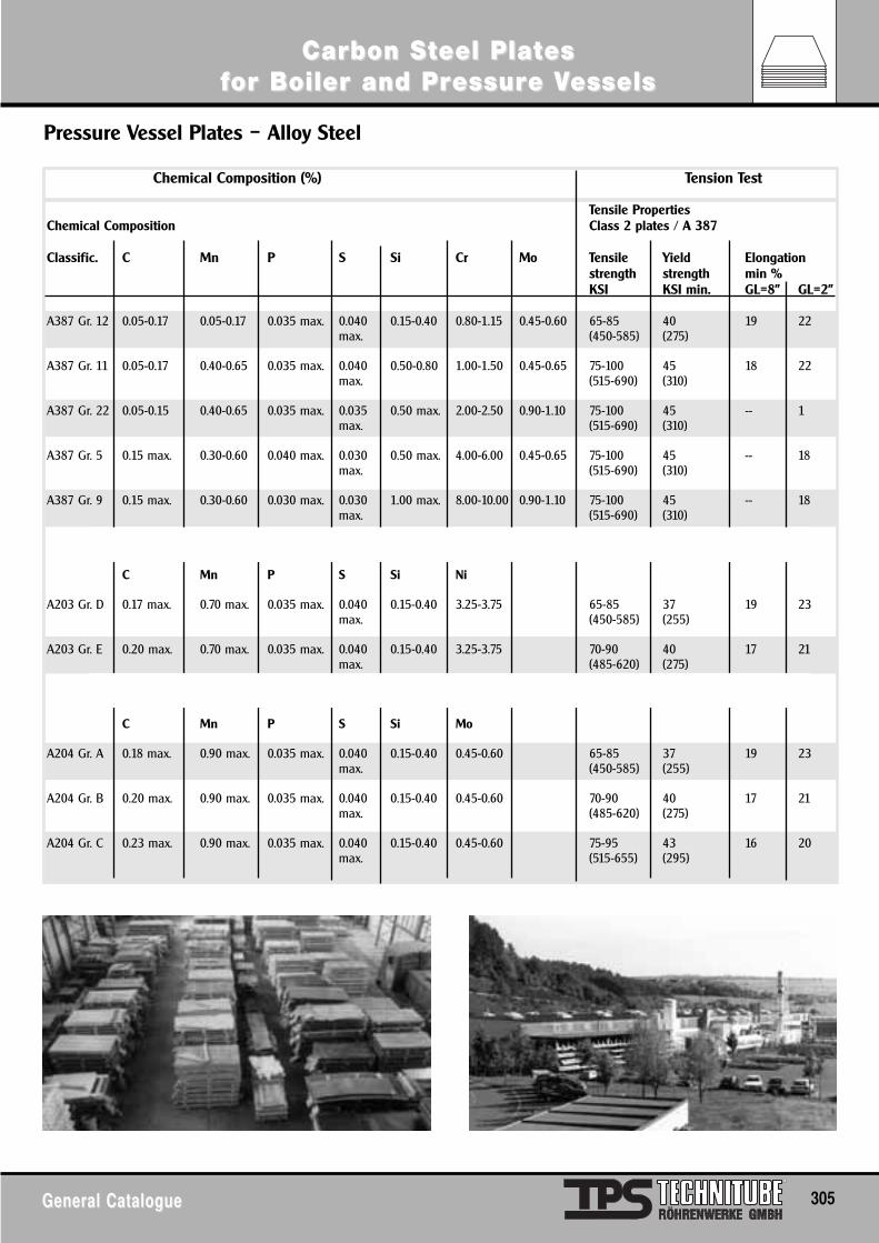
General CatalogueGeneral Catalogue 305
Carbon SCarbon Stteel Plateel Platesesffor Boiler and Pror Boiler and Pressuressure Ve Vesselsessels
Pressure Vessel Plates – Alloy Steel
Chemical Composition (%) Tension Test
Tensile PropertiesChemical Composition Class 2 plates / A 387
Classific. C Mn P S Si Cr Mo Tensile Yield Elongationstrength strength min %KSI KSI min. GL=8" GL=2"
A387 Gr. 12 0.05-0.17 0.05-0.17 0.035 max. 0.040 0.15-0.40 0.80-1.15 0.45-0.60 65-85 40 19 22max. (450-585) (275)
A387 Gr. 11 0.05-0.17 0.40-0.65 0.035 max. 0.040 0.50-0.80 1.00-1.50 0.45-0.65 75-100 45 18 22max. (515-690) (310)
A387 Gr. 22 0.05-0.15 0.40-0.65 0.035 max. 0.035 0.50 max. 2.00-2.50 0.90-1.10 75-100 45 -- 1max. (515-690) (310)
A387 Gr. 5 0.15 max. 0.30-0.60 0.040 max. 0.030 0.50 max. 4.00-6.00 0.45-0.65 75-100 45 -- 18max. (515-690) (310)
A387 Gr. 9 0.15 max. 0.30-0.60 0.030 max. 0.030 1.00 max. 8.00-10.00 0.90-1.10 75-100 45 -- 18max. (515-690) (310)
C Mn P S Si Ni
A203 Gr. D 0.17 max. 0.70 max. 0.035 max. 0.040 0.15-0.40 3.25-3.75 65-85 37 19 23max. (450-585) (255)
A203 Gr. E 0.20 max. 0.70 max. 0.035 max. 0.040 0.15-0.40 3.25-3.75 70-90 40 17 21max. (485-620) (275)
C Mn P S Si Mo
A204 Gr. A 0.18 max. 0.90 max. 0.035 max. 0.040 0.15-0.40 0.45-0.60 65-85 37 19 23max. (450-585) (255)
A204 Gr. B 0.20 max. 0.90 max. 0.035 max. 0.040 0.15-0.40 0.45-0.60 70-90 40 17 21max. (485-620) (275)
A204 Gr. C 0.23 max. 0.90 max. 0.035 max. 0.040 0.15-0.40 0.45-0.60 75-95 43 16 20max. (515-655) (295)
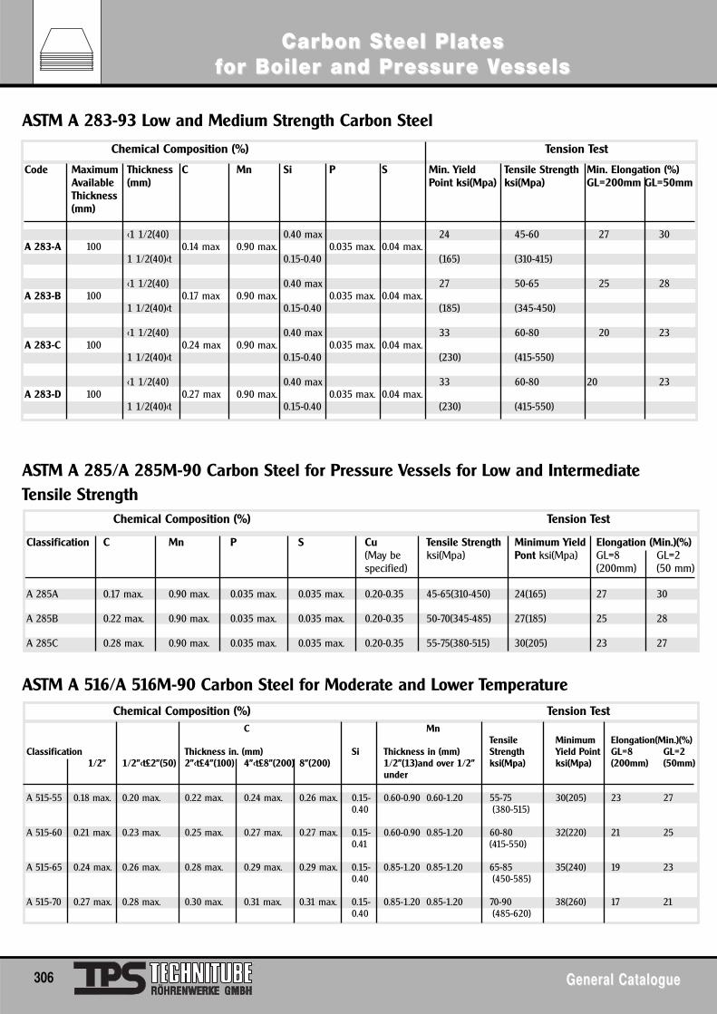
C MnTensile Minimum Elongation(Min.)(%)
Classification Thickness in. (mm) Si Thickness in (mm) Strength Yield Point GL=8 GL=21/2" 1/2"<t£2"(50) 2"<t£4"(100) 4"<t£8"(200) 8"(200) 1/2"(13)and over 1/2" ksi(Mpa) ksi(Mpa) (200mm) (50mm)
under
A 515-55 0.18 max. 0.20 max. 0.22 max. 0.24 max. 0.26 max. 0.15- 0.60-0.90 0.60-1.20 55-75 30(205) 23 270.40 (380-515)
A 515-60 0.21 max. 0.23 max. 0.25 max. 0.27 max. 0.27 max. 0.15- 0.60-0.90 0.85-1.20 60-80 32(220) 21 250.41 (415-550)
A 515-65 0.24 max. 0.26 max. 0.28 max. 0.29 max. 0.29 max. 0.15- 0.85-1.20 0.85-1.20 65-85 35(240) 19 230.40 (450-585)
A 515-70 0.27 max. 0.28 max. 0.30 max. 0.31 max. 0.31 max. 0.15- 0.85-1.20 0.85-1.20 70-90 38(260) 17 210.40 (485-620)
ASTM A 283-93 Low and Medium Strength Carbon Steel
ASTM A 285/A 285M-90 Carbon Steel for Pressure Vessels for Low and Intermediate Tensile Strength
ASTM A 516/A 516M-90 Carbon Steel for Moderate and Lower Temperature
Chemical Composition (%) Tension Test
Code Maximum Thickness C Mn Si P S Min. Yield Tensile Strength Min. Elongation (%)Available (mm) Point ksi(Mpa) ksi(Mpa) GL=200mm GL=50mmThickness(mm)
<1 1/2(40) 0.40 max 24 45-60 27 30A 283-A 100 0.14 max 0.90 max. 0.035 max. 0.04 max.
1 1/2(40)<t 0.15-0.40 (165) (310-415)
<1 1/2(40) 0.40 max 27 50-65 25 28A 283-B 100 0.17 max 0.90 max. 0.035 max. 0.04 max.
1 1/2(40)<t 0.15-0.40 (185) (345-450)
<1 1/2(40) 0.40 max 33 60-80 20 23A 283-C 100 0.24 max 0.90 max. 0.035 max. 0.04 max.
1 1/2(40)<t 0.15-0.40 (230) (415-550)
<1 1/2(40) 0.40 max 33 60-80 20 23A 283-D 100 0.27 max 0.90 max. 0.035 max. 0.04 max.
1 1/2(40)<t 0.15-0.40 (230) (415-550)
Classification C Mn P S Cu Tensile Strength Minimum Yield Elongation (Min.)(%)(May be ksi(Mpa) Pont ksi(Mpa) GL=8 GL=2specified) (200mm) (50 mm)
A 285A 0.17 max. 0.90 max. 0.035 max. 0.035 max. 0.20-0.35 45-65(310-450) 24(165) 27 30
A 285B 0.22 max. 0.90 max. 0.035 max. 0.035 max. 0.20-0.35 50-70(345-485) 27(185) 25 28
A 285C 0.28 max. 0.90 max. 0.035 max. 0.035 max. 0.20-0.35 55-75(380-515) 30(205) 23 27
Chemical Composition (%) Tension Test
Chemical Composition (%) Tension Test
306 General CatalogueGeneral Catalogue
Carbon SCarbon Stteel Plateel Platesesffor Boiler and Pror Boiler and Pressuressure Ve Vesselsessels
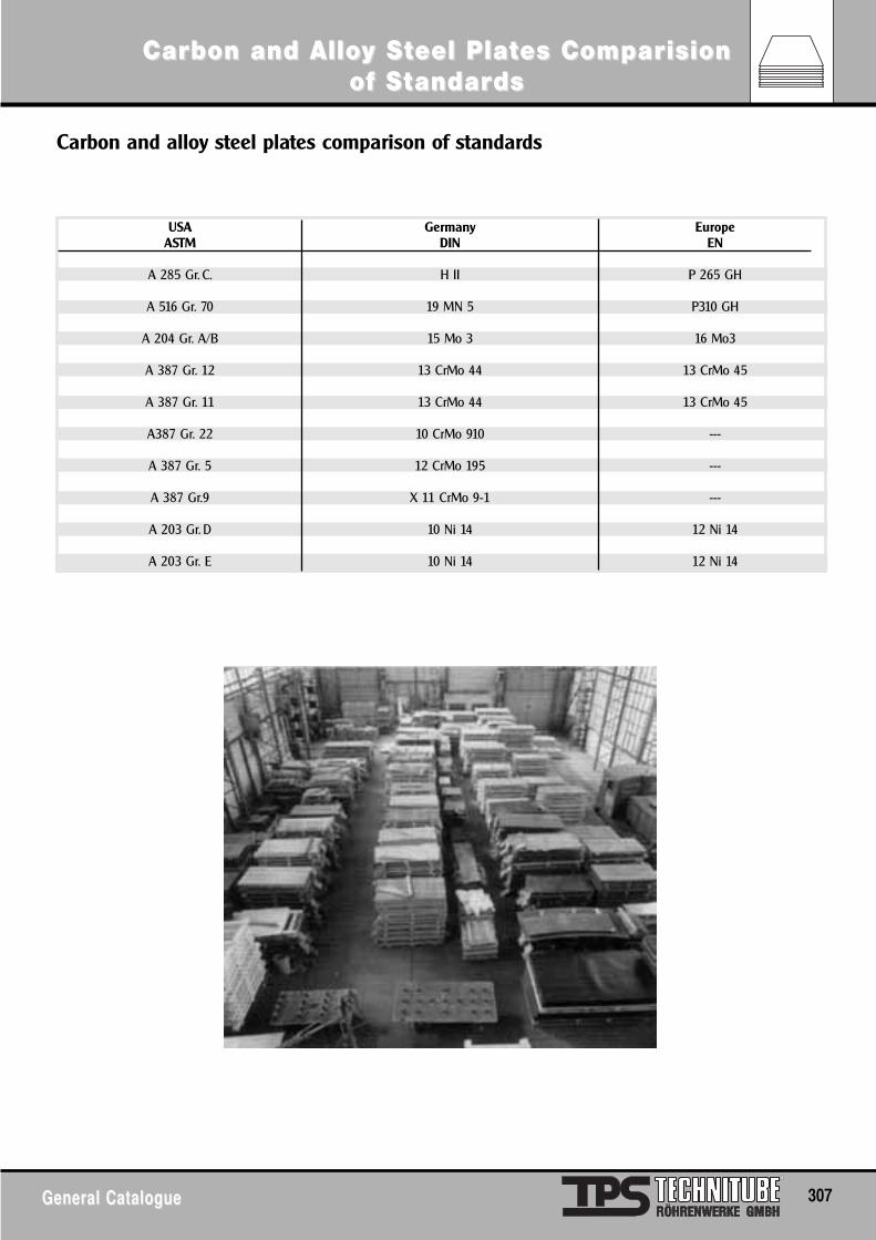
General CatalogueGeneral Catalogue 307
Carbon and AlloCarbon and Alloy Sy Stteel Plateel Plates Comes Comparparisionisionof Sof Sttandarandardsds
USA Germany EuropeASTM DIN EN
A 285 Gr. C. H II P 265 GH
A 516 Gr. 70 19 MN 5 P310 GH
A 204 Gr. A/B 15 Mo 3 16 Mo3
A 387 Gr. 12 13 CrMo 44 13 CrMo 45
A 387 Gr. 11 13 CrMo 44 13 CrMo 45
A387 Gr. 22 10 CrMo 910 ---
A 387 Gr. 5 12 CrMo 195 ---
A 387 Gr.9 X 11 CrMo 9-1 ---
A 203 Gr. D 10 Ni 14 12 Ni 14
A 203 Gr. E 10 Ni 14 12 Ni 14
Carbon and alloy steel plates comparison of standards
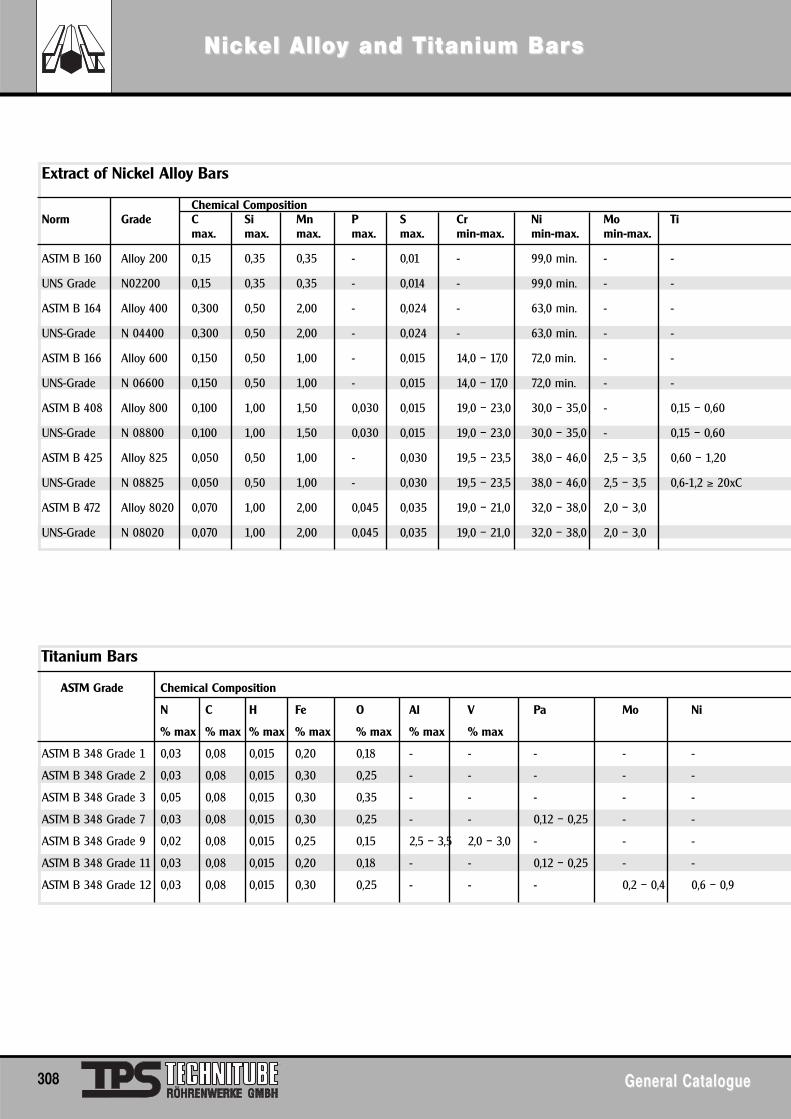
308 General CatalogueGeneral Catalogue
NicNickkel Alloel Alloy and Ty and Tititanium Baranium Barss
Extract of Nickel Alloy Bars
Chemical CompositionNorm Grade C Si Mn P S Cr Ni Mo Ti
max. max. max. max. max. min-max. min-max. min-max.
ASTM B 160 Alloy 200 0,15 0,35 0,35 - 0,01 - 99,0 min. - -
UNS Grade N02200 0,15 0,35 0,35 - 0,014 - 99,0 min. - -
ASTM B 164 Alloy 400 0,300 0,50 2,00 - 0,024 - 63,0 min. - -
UNS-Grade N 04400 0,300 0,50 2,00 - 0,024 - 63,0 min. - -
ASTM B 166 Alloy 600 0,150 0,50 1,00 - 0,015 14,0 – 17,0 72,0 min. - -
UNS-Grade N 06600 0,150 0,50 1,00 - 0,015 14,0 – 17,0 72,0 min. - -
ASTM B 408 Alloy 800 0,100 1,00 1,50 0,030 0,015 19,0 – 23,0 30,0 – 35,0 - 0,15 – 0,60
UNS-Grade N 08800 0,100 1,00 1,50 0,030 0,015 19,0 – 23,0 30,0 – 35,0 - 0,15 – 0,60
ASTM B 425 Alloy 825 0,050 0,50 1,00 - 0,030 19,5 – 23,5 38,0 – 46,0 2,5 – 3,5 0,60 – 1,20
UNS-Grade N 08825 0,050 0,50 1,00 - 0,030 19,5 – 23,5 38,0 – 46,0 2,5 – 3,5 0,6-1,2 ≥ 20xC
ASTM B 472 Alloy 8020 0,070 1,00 2,00 0,045 0,035 19,0 – 21,0 32,0 – 38,0 2,0 – 3,0
UNS-Grade N 08020 0,070 1,00 2,00 0,045 0,035 19,0 – 21,0 32,0 – 38,0 2,0 – 3,0
Titanium Bars
ASTM Grade Chemical Composition
N C H Fe O Al V Pa Mo Ni
% max % max % max % max % max % max % max
ASTM B 348 Grade 1 0,03 0,08 0,015 0,20 0,18 - - - - -
ASTM B 348 Grade 2 0,03 0,08 0,015 0,30 0,25 - - - - -
ASTM B 348 Grade 3 0,05 0,08 0,015 0,30 0,35 - - - - -
ASTM B 348 Grade 7 0,03 0,08 0,015 0,30 0,25 - - 0,12 – 0,25 - -
ASTM B 348 Grade 9 0,02 0,08 0,015 0,25 0,15 2,5 – 3,5 2,0 – 3,0 - - -
ASTM B 348 Grade 11 0,03 0,08 0,015 0,20 0,18 - - 0,12 – 0,25 - -
ASTM B 348 Grade 12 0,03 0,08 0,015 0,30 0,25 - - - 0,2 – 0,4 0,6 – 0,9
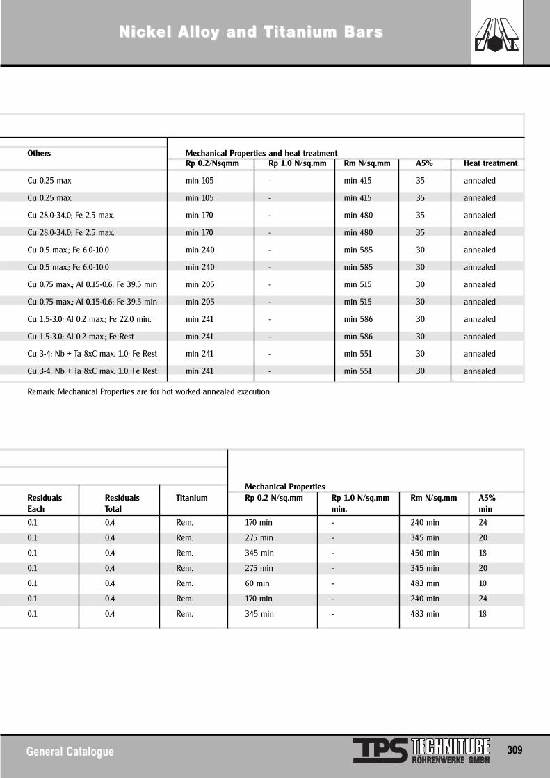
General CatalogueGeneral Catalogue 309
NicNickkel Alloel Alloy and Ty and Tititanium Baranium Barss
Mechanical PropertiesResiduals Residuals Titanium Rp 0.2 N/sq.mm Rp 1.0 N/sq.mm Rm N/sq.mm A5%Each Total min. min
0.1 0.4 Rem. 170 min - 240 min 24
0.1 0.4 Rem. 275 min - 345 min 20
0.1 0.4 Rem. 345 min - 450 min 18
0.1 0.4 Rem. 275 min - 345 min 20
0.1 0.4 Rem. 60 min - 483 min 10
0.1 0.4 Rem. 170 min - 240 min 24
0.1 0.4 Rem. 345 min - 483 min 18
Others Mechanical Properties and heat treatmentRp 0.2/Nsqmm Rp 1.0 N/sq.mm Rm N/sq.mm A5% Heat treatment
Cu 0.25 max min 105 - min 415 35 annealed
Cu 0.25 max. min 105 - min 415 35 annealed
Cu 28.0-34.0; Fe 2.5 max. min 170 - min 480 35 annealed
Cu 28.0-34.0; Fe 2.5 max. min 170 - min 480 35 annealed
Cu 0.5 max.; Fe 6.0-10.0 min 240 - min 585 30 annealed
Cu 0.5 max.; Fe 6.0-10.0 min 240 - min 585 30 annealed
Cu 0.75 max.; Al 0.15-0.6; Fe 39.5 min min 205 - min 515 30 annealed
Cu 0.75 max.; Al 0.15-0.6; Fe 39.5 min min 205 - min 515 30 annealed
Cu 1.5-3.0; Al 0.2 max.; Fe 22.0 min. min 241 - min 586 30 annealed
Cu 1.5-3.0; Al 0.2 max.; Fe Rest min 241 - min 586 30 annealed
Cu 3-4; Nb + Ta 8xC max. 1.0; Fe Rest min 241 - min 551 30 annealed
Cu 3-4; Nb + Ta 8xC max. 1.0; Fe Rest min 241 - min 551 30 annealed
Remark: Mechanical Properties are for hot worked annealed execution
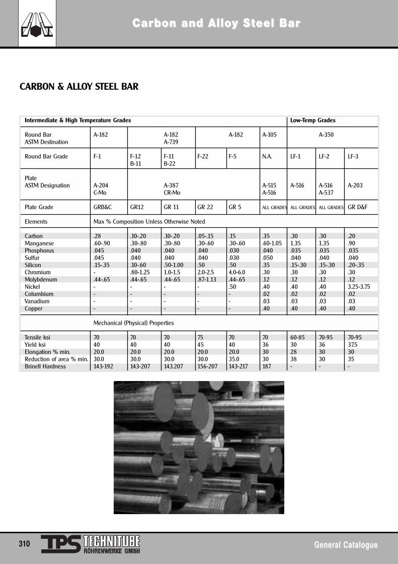
CARBON & ALLOY STEEL BAR
Intermediate & High Temperature Grades Low-Temp Grades
Round Bar A-182 A-182 A-182 A-105 A-350ASTM Destination A-739
Round Bar Grade F-1 F-12 F-11 F-22 F-5 N.A. LF-1 LF-2 LF-3B-11 B-22
PlateASTM Designation A-204 A-387 A-515 A-516 A-516 A-203
C-Mo CR-Mo A-516 A-537
Plate Grade GRB&C GR12 GR 11 GR 22 GR 5 ALL GRADES ALL GRADES ALL GRADES GR D&F
Elements Max % Composition Unless Otherwise Noted
Carbon .28 .10-.20 .10-.20 .05-.15 .15 .35 .30 .30 .20Manganese .60-.90 .30-.80 .30-.80 .30-.60 .30-.60 .60-1.05 1.35 1.35 .90Phosphorus .045 .040 .040 .040 .030 .040 .035 .035 .035Sulfur .045 .040 .040 .040 .030 .050 .040 .040 .040Silicon .15-.35 .10-.60 .50-1.00 .50 .50 .35 .15-.30 .15-.30 .20-.35Chromium - .80-1.25 1.0-1.5 2.0-2.5 4.0-6.0 .30 .30 .30 .30Molybdenum .44-.65 .44-.65 .44-.65 .87-1.13 .44-.65 .12 .12 .12 .12Nickel - - - - .50 .40 .40 .40 3.25-3.75Columbium - - - - - .02 .02 .02 .02Vanadium - - - - - .03 .03 .03 .03Copper - - - - - .40 .40 .40 .40
Mechanical (Physical) Properties
Tensile ksi 70 70 70 75 70 70 60-85 70-95 70-95Yield ksi 40 40 40 45 40 36 30 36 37.5Elongation % min. 20.0 20.0 20.0 20.0 20.0 30 28 30 30Reduction of area % min. 30.0 30.0 30.0 30.0 35.0 30 38 30 35Brinell Hardness 143-192 143-207 143.207 156-207 143-217 187 - - -
310 General CatalogueGeneral Catalogue
Carbon and AlloCarbon and Alloy Sy Stteel Bareel Bar
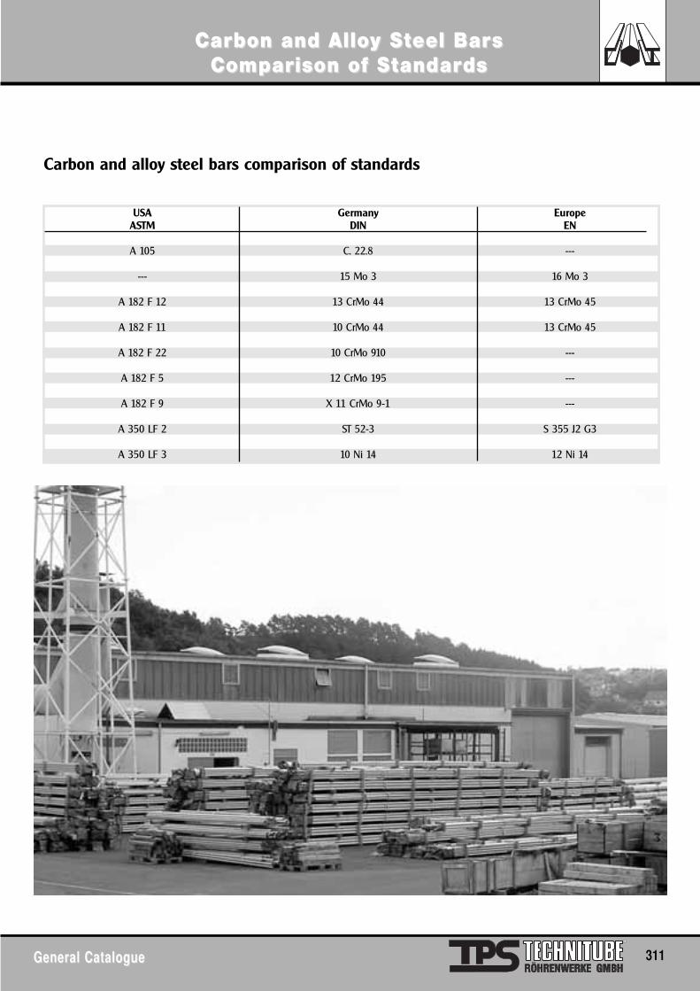
General CatalogueGeneral Catalogue 311
Carbon and AlloCarbon and Alloy Sy Stteel Bareel Bars s ComComparparison of Sison of Sttandarandardsds
USA Germany EuropeASTM DIN EN
A 105 C. 22.8 ---
--- 15 Mo 3 16 Mo 3
A 182 F 12 13 CrMo 44 13 CrMo 45
A 182 F 11 10 CrMo 44 13 CrMo 45
A 182 F 22 10 CrMo 910 ---
A 182 F 5 12 CrMo 195 ---
A 182 F 9 X 11 CrMo 9-1 ---
A 350 LF 2 ST 52-3 S 355 J2 G3
A 350 LF 3 10 Ni 14 12 Ni 14
Carbon and alloy steel bars comparison of standards
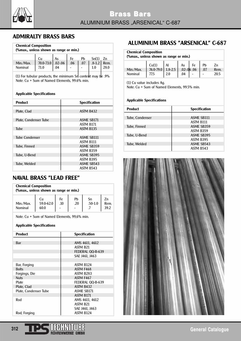
Chemical Composition(%max., unless shown as range or min.)
Cu As Fe Pb Sn(1) ZnMin./Max. 70.0-73.0 .02-.06 .06 .07 .8-1.2 Rem.Nominal 71.0 .04 - - 1.0 28.0
(1) For tubular products, the minimum Sn content may be .9%Note: Cu + Sum of Named Elements, 99.6% min.
Applicable Specifications
Product Specification
Plate, Clad ASTM B432
Plate, Condenser Tube ASME SB171ASTM B171
Tube ASTM B135
Tube Condenser ASME SB111ASTM B111
Tube, Finned ASME SB359ASTM B359
Tube, U-Bend ASME SB395ASTM B395
Tube, Welded ASME SB543ASTM B543
ADMIRALTY BRASS BARS
NAVAL BRASS "LEAD FREE"
ALUMINIUM BRASS "ARSENICAL" C-687Chemical Composition(%max., unless shown as range or min.)
Cu(1) Al As Fe Pb ZnMin./Max. 76.0-79.0 1.8-2.5 .02-.06 .06 .07 Rem.Nominal 77.5 2.0 .04 - - 20.5
(1) Cu value includes Ag.Note: Cu + Sum of Named Elements, 99.5% min.
Applicable Specifications
Product Specification
Tube, Condenser ASME SB111ASTM B111
Tube, Finned ASME SB359ASTM B359
Tube, U-Bend ASME SB395ASTM B395
Tube, Welded ASME SB543ASTM B543
Chemical Composition(%max., unless shown as range or min.)
Cu Fe Pb Sn ZnMin./Max. 59.0-62.0 .10 .20 .50-1.0 Rem.Nominal 60.0 - - .7 39.2
Note: Cu + Sum of Named Elements, 99,6% min.
Applicable Specifications
Product Specification
Bar AMS 4611, 4612ASTM B21FEDERAL QQ-B-639SAE J461, J463
Bar, Forging ASTM B124Bolts ASTM F468Forgings, Die ASTM B283Nuts ASTM F467Plate FEDERAL QQ-B-639Plate, Clad ASTM B432Plate, Condenser Tube ASME SB171
ASTM B171Rod AMS 4611, 4612
ASTM B21SAE J461, J463
Rod, Forging ASTM B124
312 General CatalogueGeneral Catalogue
BrBrass Barass BarssALUMINIUM BRASS „ARSENICAL“ C-687
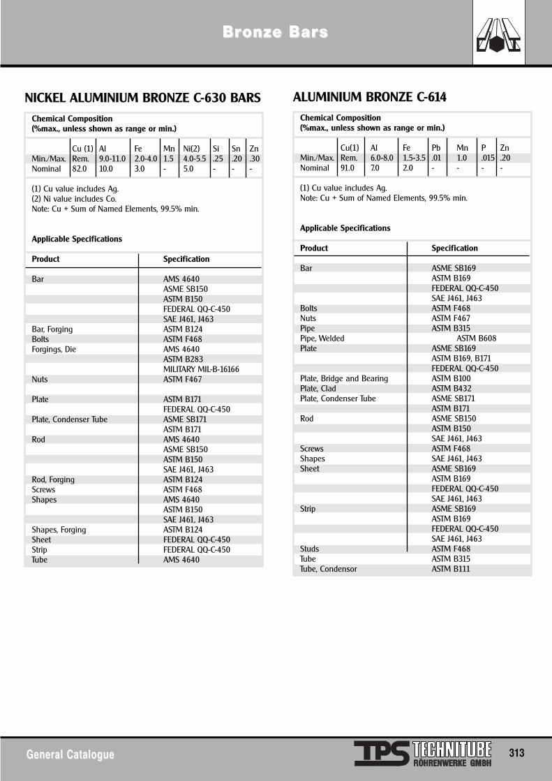
General CatalogueGeneral Catalogue 313
BrBronze Baronze Barss
Chemical Composition(%max., unless shown as range or min.)
Cu (1) Al Fe Mn Ni(2) Si Sn ZnMin./Max. Rem. 9.0-11.0 2.0-4.0 1.5 4.0-5.5 .25 .20 .30Nominal 82.0 10.0 3.0 - 5.0 - - -
(1) Cu value includes Ag.(2) Ni value includes Co.Note: Cu + Sum of Named Elements, 99.5% min.
Applicable Specifications
Product Specification
Bar AMS 4640ASME SB150ASTM B150FEDERAL QQ-C-450SAE J461, J463
Bar, Forging ASTM B124Bolts ASTM F468Forgings, Die AMS 4640
ASTM B283MILITARY MIL-B-16166
Nuts ASTM F467
Plate ASTM B171FEDERAL QQ-C-450
Plate, Condenser Tube ASME SB171ASTM B171
Rod AMS 4640ASME SB150ASTM B150SAE J461, J463
Rod, Forging ASTM B124Screws ASTM F468Shapes AMS 4640
ASTM B150SAE J461, J463
Shapes, Forging ASTM B124Sheet FEDERAL QQ-C-450Strip FEDERAL QQ-C-450Tube AMS 4640
NICKEL ALUMINIUM BRONZE C-630 BARSChemical Composition(%max., unless shown as range or min.)
Cu(1) Al Fe Pb Mn P ZnMin./Max. Rem. 6.0-8.0 1.5-3.5 .01 1.0 .015 .20Nominal 91.0 7.0 2.0 - - - -
(1) Cu value includes Ag.Note: Cu + Sum of Named Elements, 99.5% min.
Applicable Specifications
Product Specification
Bar ASME SB169ASTM B169FEDERAL QQ-C-450SAE J461, J463
Bolts ASTM F468Nuts ASTM F467Pipe ASTM B315Pipe, Welded ASTM B608Plate ASME SB169
ASTM B169, B171FEDERAL QQ-C-450
Plate, Bridge and Bearing ASTM B100Plate, Clad ASTM B432Plate, Condenser Tube ASME SB171
ASTM B171Rod ASME SB150
ASTM B150SAE J461, J463
Screws ASTM F468Shapes SAE J461, J463Sheet ASME SB169
ASTM B169FEDERAL QQ-C-450SAE J461, J463
Strip ASME SB169ASTM B169FEDERAL QQ-C-450SAE J461, J463
Studs ASTM F468Tube ASTM B315Tube, Condensor ASTM B111
ALUMINIUM BRONZE C-614
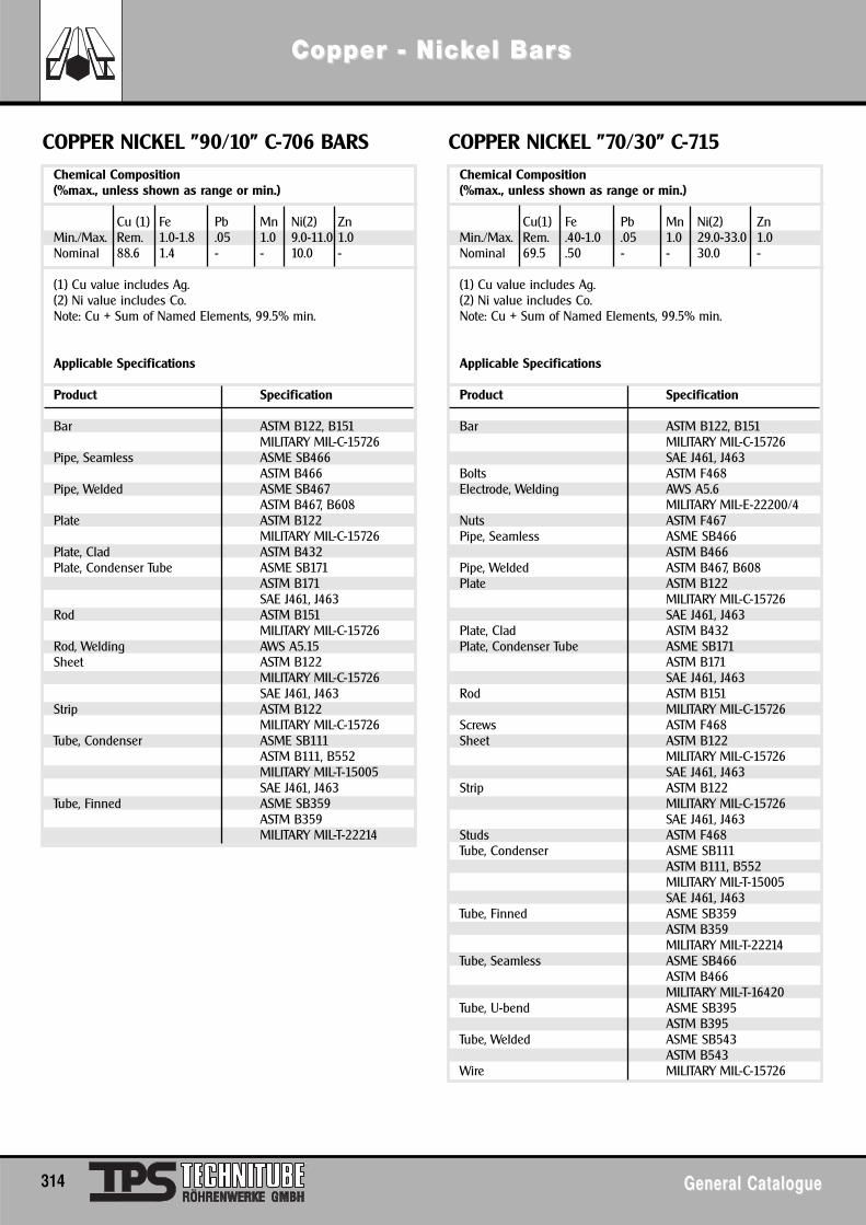
Chemical Composition(%max., unless shown as range or min.)
Cu (1) Fe Pb Mn Ni(2) ZnMin./Max. Rem. 1.0-1.8 .05 1.0 9.0-11.0 1.0Nominal 88.6 1.4 - - 10.0 -
(1) Cu value includes Ag.(2) Ni value includes Co.Note: Cu + Sum of Named Elements, 99.5% min.
Applicable Specifications
Product Specification
Bar ASTM B122, B151MILITARY MIL-C-15726
Pipe, Seamless ASME SB466ASTM B466
Pipe, Welded ASME SB467ASTM B467, B608
Plate ASTM B122MILITARY MIL-C-15726
Plate, Clad ASTM B432Plate, Condenser Tube ASME SB171
ASTM B171SAE J461, J463
Rod ASTM B151MILITARY MIL-C-15726
Rod, Welding AWS A5.15Sheet ASTM B122
MILITARY MIL-C-15726SAE J461, J463
Strip ASTM B122MILITARY MIL-C-15726
Tube, Condenser ASME SB111ASTM B111, B552MILITARY MIL-T-15005SAE J461, J463
Tube, Finned ASME SB359ASTM B359MILITARY MIL-T-22214
COPPER NICKEL "90/10" C-706 BARSChemical Composition(%max., unless shown as range or min.)
Cu(1) Fe Pb Mn Ni(2) ZnMin./Max. Rem. .40-1.0 .05 1.0 29.0-33.0 1.0Nominal 69.5 .50 - - 30.0 -
(1) Cu value includes Ag.(2) Ni value includes Co.Note: Cu + Sum of Named Elements, 99.5% min.
Applicable Specifications
Product Specification
Bar ASTM B122, B151MILITARY MIL-C-15726SAE J461, J463
Bolts ASTM F468Electrode, Welding AWS A5.6
MILITARY MIL-E-22200/4Nuts ASTM F467Pipe, Seamless ASME SB466
ASTM B466Pipe, Welded ASTM B467, B608Plate ASTM B122
MILITARY MIL-C-15726SAE J461, J463
Plate, Clad ASTM B432Plate, Condenser Tube ASME SB171
ASTM B171SAE J461, J463
Rod ASTM B151MILITARY MIL-C-15726
Screws ASTM F468Sheet ASTM B122
MILITARY MIL-C-15726SAE J461, J463
Strip ASTM B122MILITARY MIL-C-15726SAE J461, J463
Studs ASTM F468Tube, Condenser ASME SB111
ASTM B111, B552MILITARY MIL-T-15005SAE J461, J463
Tube, Finned ASME SB359ASTM B359MILITARY MIL-T-22214
Tube, Seamless ASME SB466ASTM B466MILITARY MIL-T-16420
Tube, U-bend ASME SB395ASTM B395
Tube, Welded ASME SB543ASTM B543
Wire MILITARY MIL-C-15726
COPPER NICKEL "70/30" C-715
314 General CatalogueGeneral Catalogue
Copper - NicCopper - Nickkel Barel Barss
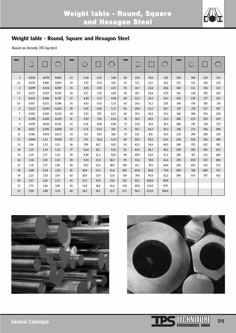
General CatalogueGeneral Catalogue 315
WWeight teight table - Rable - Round, Sqound, Squaruare e and Heand Hexxagon Sagon Stteeleel
mm mm mm mm
3 0,056 0,070 0,061 23 3,26 4,15 3,60 50 15,4 19,6 17,0 130 104 133 115
3.5 0,076 0,100 0,083 24 3,55 4,52 3,91 53 17,3 22,1 19,1 135 112 143 124
4 0,099 0,126 0,109 25 3,85 4,91 4,25 55 18,7 23,8 20,6 140 121 154 133
4.5 0,125 0,159 0,138 26 4,17 5,31 4,60 58 20,7 26,4 22,9 145 130 165 143
5 0,154 0,196 0,170 27 4,50 5,72 4,96 60 22,2 28,3 24,5 150 139 177 153
5,5 0,187 0,237 0,206 28 4,83 6,15 5,33 63 24,5 31,2 27,0 160 158 201 174
6 0,222 0,283 0,245 29 5,19 6,61 5,72 65 26,0 33,2 28,7 170 178 227 197
7 0,302 0,385 0,333 30 5,55 7,07 6,12 68 28,5 36,3 31,4 180 200 254 220
8 0,395 0,502 0,435 31 5,92 7,54 6,54 70 30,2 38,5 33,3 190 223 283 245
9 0,499 0,636 0,551 32 6,31 8,04 6,96 73 32,9 41,8 36,3 200 247 314 272
10 0,617 0,785 0,680 33 6,71 8,55 7,41 75 34,7 44,2 38,3 210 272 346 300
11 0,746 0,950 0,823 34 7,13 9,07 7,86 78 37,5 47,8 41,4 220 298 380 329
12 0,888 1,13 0,980 35 7,55 9,62 8,33 80 39,5 50,2 43,5 230 326 415 360
13 1,04 1,33 1,15 36 7,99 10,2 8,81 83 42,5 54,4 46,9 240 355 452 392
14 1,21 1,54 1,33 37 8,44 10,7 9,31 85 44,5 56,7 49,1 250 385 491 425
15 1,39 1,77 1,53 38 8,90 11,3 9,82 90 49,9 63,6 55,1 260 417 531 460
16 1,58 2,01 1,74 39 9,38 11,9 10,3 95 55,6 70,8 61,4 270 450 572 496
17 1,78 2,27 1,96 40 9,87 12,6 10,9 100 61,7 78,5 68,0 280 483 615 533
18 2,00 2,54 2,20 41 10,4 13,2 11,4 105 68,0 86,6 75,0 290 519 660 572
19 2,23 2,83 2,45 42 10,9 13,9 12,0 110 74,6 95,0 82,2 300 555 707 612
20 2,47 3,14 2,72 45 12,5 15,9 13,8 115 81,5 104,0 89,9
21 2,72 3,46 3,00 46 13,0 16,6 14,4 120 88,8 113,0 97,9
22 2,98 3,80 3,29 48 14,2 18,1 15,7 125 96,3 123,0 106,0
Based on Density 7,85 kg/dm3
Weight table - Round, Square and Hexagon Steel
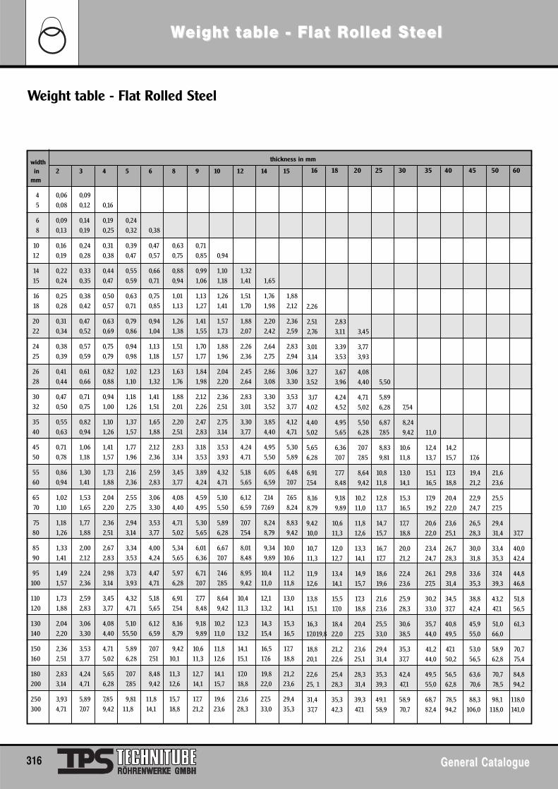
Weight table - Flat Rolled Steel
width in 2 3 4 5 6 8 9 10 12 14 15
mm
4 0,06 0,09
5 0,08 0,12 0,16
6 0,09 0,14 0,19 0,24
8 0,13 0,19 0,25 0,32 0,38
10 0,16 0,24 0,31 0,39 0,47 0,63 0,71
12 0,19 0,28 0,38 0,47 0,57 0,75 0,85 0,94
14 0,22 0,33 0,44 0,55 0,66 0,88 0,99 1,10 1,32
15 0,24 0,35 0,47 0,59 0,71 0,94 1,06 1,18 1,41 1,65
16 0,25 0,38 0,50 0,63 0,75 1,01 1,13 1,26 1,51 1,76 1,88
18 0,28 0,42 0,57 0,71 0,85 1,13 1,27 1,41 1,70 1,98 2,12
20 0,31 0,47 0,63 0,79 0,94 1,26 1,41 1,57 1,88 2,20 2,36
22 0,34 0,52 0,69 0,86 1,04 1,38 1,55 1,73 2,07 2,42 2,59
24 0,38 0,57 0,75 0,94 1,13 1,51 1,70 1,88 2,26 2,64 2,83
25 0,39 0,59 0,79 0,98 1,18 1,57 1,77 1,96 2,36 2,75 2,94
26 0,41 0,61 0,82 1,02 1,23 1,63 1,84 2,04 2,45 2,86 3,06
28 0,44 0,66 0,88 1,10 1,32 1,76 1,98 2,20 2,64 3,08 3,30
30 0,47 0,71 0,94 1,18 1,41 1,88 2,12 2,36 2,83 3,30 3,53
32 0,50 0,75 1,00 1,26 1,51 2,01 2,26 2,51 3,01 3,52 3,77
35 0,55 0,82 1,10 1,37 1,65 2,20 2,47 2,75 3,30 3,85 4,12
40 0,63 0,94 1,26 1,57 1,88 2,51 2,83 3,14 3,77 4,40 4,71
45 0,71 1,06 1,41 1,77 2,12 2,83 3,18 3,53 4,24 4,95 5,30
50 0,78 1,18 1,57 1,96 2,36 3,14 3,53 3,93 4,71 5,50 5,89
55 0,86 1,30 1,73 2,16 2,59 3,45 3,89 4,32 5,18 6,05 6,48
60 0,94 1,41 1,88 2,36 2,83 3,77 4,24 4,71 5,65 6,59 7,07
65 1,02 1,53 2,04 2,55 3,06 4,08 4,59 5,10 6,12 7,14 7,65
70 1,10 1,65 2,20 2,75 3,30 4,40 4,95 5,50 6,59 77,69 8,24
75 1,18 1,77 2,36 2,94 3,53 4,71 5,30 5,89 7,07 8,24 8,83
80 1,26 1,88 2,51 3,14 3,77 5,02 5,65 6,28 7,54 8,79 9,42
85 1,33 2,00 2,67 3,34 4,00 5,34 6,01 6,67 8,01 9,34 10,0
90 1,41 2,12 2,83 3,53 4,24 5,65 6,36 7,07 8,48 9,89 10,6
95 1,49 2,24 2,98 3,73 4,47 5,97 6,71 7,46 8,95 10,4 11,2
100 1,57 2,36 3,14 3,93 4,71 6,28 7,07 7,85 9,42 11,0 11,8
110 1,73 2,59 3,45 4,32 5,18 6,91 7,77 8,64 10,4 12,1 13,0
120 1,88 2,83 3,77 4,71 5,65 7,54 8,48 9,42 11,3 13,2 14,1
130 2,04 3,06 4,08 5,10 6,12 8,16 9,18 10,2 12,3 14,3 15,3
140 2,20 3,30 4,40 55,50 6,59 8,79 9,89 11,0 13,2 15,4 16,5
150 2,36 3,53 4,71 5,89 7,07 9,42 10,6 11,8 14,1 16,5 17,7
160 2,51 3,77 5,02 6,28 7,51 10,1 11,3 12,6 15,1 17,6 18,8
180 2,83 4,24 5,65 7,07 8,48 11,3 12,7 14,1 17,0 19,8 21,2
200 3,14 4,71 6,28 7,85 9,42 12,6 14,1 15,7 18,8 22,0 23,6
250 3,93 5,89 7,85 9,81 11,8 15,7 17,7 19,6 23,6 27,5 29,4
300 4,71 7,07 9,42 11,8 14,1 18,8 21,2 23,6 28,3 33,0 35,3
thickness in mm
16 18 20 25 30 35 40 45 50 60
2,26
2,51 2,83
2,76 3,11 3,45
3,01 3,39 3,77
3,14 3,53 3,93
3,27 3,67 4,08
3,52 3,96 4,40 5,50
3,î7 4,24 4,71 5,89
4,02 4,52 5,02 6,28 7,54
4,40 4,95 5,50 6,87 8,24
5,02 5,65 6,28 7,85 9,42 11,0
5,65 6,36 7,07 8,83 10,6 12,4 14,2
6,28 7,07 7,85 9,81 11,8 13,7 15,7 17,6
6,91 7,77 8,64 10,8 13,0 15,1 17,3 19,4 21,6
7,54 8,48 9,42 11,8 14,1 16,5 18,8 21,2 23,6
8,16 9,18 10,2 12,8 15,3 17,9 20,4 22,9 25,5
8,79 9,89 11,0 13,7 16,5 19,2 22,0 24,7 27,5
9,42 10,6 11,8 14,7 17,7 20,6 23,6 26,5 29,4
10,0 11,3 12,6 15,7 18,8 22,0 25,1 28,3 31,4 37,7
10,7 12,0 13,3 16,7 20,0 23,4 26,7 30,0 33,4 40,0
11,3 12,7 14,1 17,7 21,2 24,7 28,3 31,8 35,3 42,4
11,9 13,4 14,9 18,6 22,4 26,1 29,8 33,6 37,4 44,8
12,6 14,1 15,7 19,6 23,6 27,5 31,4 35,3 39,3 46,8
13,8 15,5 17,3 21,6 25,9 30,2 34,5 38,8 43,2 51,8
15,1 17,0 18,8 23,6 28,3 33,0 37,7 42,4 47,1 56,5
16,3 18,4 20,4 25,5 30,6 35,7 40,8 45,9 51,0 61,3
17,019,8 22,0 27,5 33,0 38,5 44,0 49,5 55,0 66,0
18,8 21,2 23,6 29,4 35,3 41,2 47,1 53,0 58,9 70,7
20,1 22,6 25,1 31,4 37,7 44,0 50,2 56,5 62,8 75,4
22,6 25,4 28,3 35,3 42,4 49,5 56,5 63,6 70,7 84,8
25, 1 28,3 31,4 39,3 47,1 55,0 62,8 70,6 78,5 94,2
31,4 35,3 39,3 49,1 58,9 68,7 78,5 88,3 98,1 118,0
37,7 42,3 47,1 58,9 70,7 82,4 94,2 106,0 118,0 141,0
316 General CatalogueGeneral Catalogue
WWeight teight table - Flat Rable - Flat Rolled Solled Stteeleel
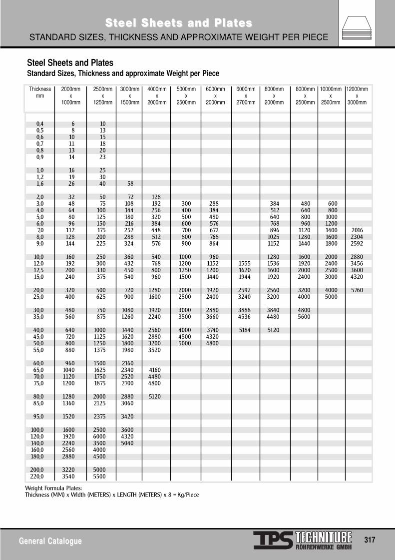
General CatalogueGeneral Catalogue 317
SStteel Sheeeel Sheets and Platts and PlatesesSTANDARD SIZES, THICKNESS AND APPROXIMATE WEIGHT PER PIECE
0,4 6 100,5 8 130,6 10 150,7 11 180,8 13 200,9 14 23
1,0 16 251,2 19 301,6 26 40 58
2,0 32 50 72 1283,0 48 75 108 192 300 288 384 480 6004,0 64 100 144 256 400 384 512 640 8005,0 80 125 180 320 500 480 640 800 10006,0 96 150 216 384 600 576 768 960 12007,0 112 175 252 448 700 672 896 1120 1400 20168,0 128 200 288 512 800 768 1025 1280 1600 23049,0 144 225 324 576 900 864 1152 1440 1800 2592
10,0 160 250 360 540 1000 960 1280 1600 2000 288012,0 192 300 432 768 1200 1152 1555 1536 1920 2400 345612,5 200 330 450 800 1250 1200 1620 1600 2000 2500 360015,0 240 375 540 960 1500 1440 1944 1920 2400 3000 4320
20,0 320 500 720 1280 2000 1920 2592 2560 3200 4000 576025,0 400 625 900 1600 2500 2400 3240 3200 4000 5000
30,0 480 750 1080 1920 3000 2880 3888 3840 480035,0 560 875 1260 2240 3500 3660 4536 4480 5600
40,0 640 1000 1440 2560 4000 3740 5184 512045,0 720 1125 1620 2880 4500 432050,0 800 1250 1800 3200 5000 480055,0 880 1375 1980 3520
60,0 960 1500 216065,0 1040 1625 2340 416070,0 1120 1750 2520 448075,0 1200 1875 2700 4800
80,0 1280 2000 2880 512085,0 1360 2125 3060
95,0 1520 2375 3420
100,0 1600 2500 3600120,0 1920 6000 4320140,0 2240 3500 5040160,0 2560 4000180,0 2880 4500
200,0 3220 5000220,0 3540 5500
Thickness 2000mm 2500mm 3000mm 4000mm 5000mm 6000mm 6000mm 8000mm 8000mm 10000mm 12000mmmm x x x x x x x x x x x
1000mm 1250mm 1500mm 2000mm 2500mm 2000mm 2700mm 2000mm 2500mm 2500mm 3000mm
Weight Formula Plates:Thickness (MM) x WIdth (METERS) x LENGTH (METERS) x 8 = Kg/Piece
Steel Sheets and PlatesStandard Sizes, Thickness and approximate Weight per Piece
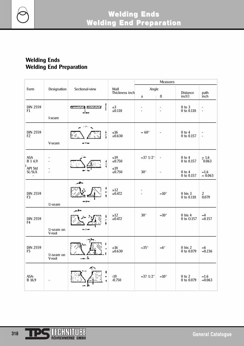
Welding EndsWelding End Preparation
Measures
Form Designation Sectional-view Wall AngleThickness inch Distance path
a ß inch') inch
DIN 2559 ≤3 - - 0 to 3 -F1 ≤0.118 - - 0 to 0.118 -
I-seam
DIN 2559 ≤16 ≈ 60° - 0 to 4 -F2 ≤0.630 0 to 0.157 -
V-seam
ASA - ≤19 ≈37 1/2° - 0 to 4 ≈ 1,6B 1 6,9 - ≤0.750 0 to 0.157 ~0.063
API Std - ≤19SL/SLX - ≤0.750 30° - 0 to 4 ≈1,6
- 0 to 0.157 ≈ 0.063
≥12 -DIN 2559 ≥0.472 - ≈10° 0 bis 3 2F3 0 to 0.118 0,079
U-seam
≥12 30° ≈10° 0 bis 4 ≈4DIN 2559 ≥0.472 0 to O.157 ≈0.157F4
U-seam on V-root
DIN 2559 ≥16 ≈35° ≈6° 0 bis 2 ≈6F5 ≥0.630 0 to 0.079 ≈0.236
U-seam onV-root
ASA- >19 ≈37 1/2° ≈10° 0 to 2 ≈1.6B 16,9 - >0.750 0 to 0.079 ≈0.063
318 General CatalogueGeneral Catalogue
WWelding Endselding EndsWWelding End Prelding End Prepareparationation
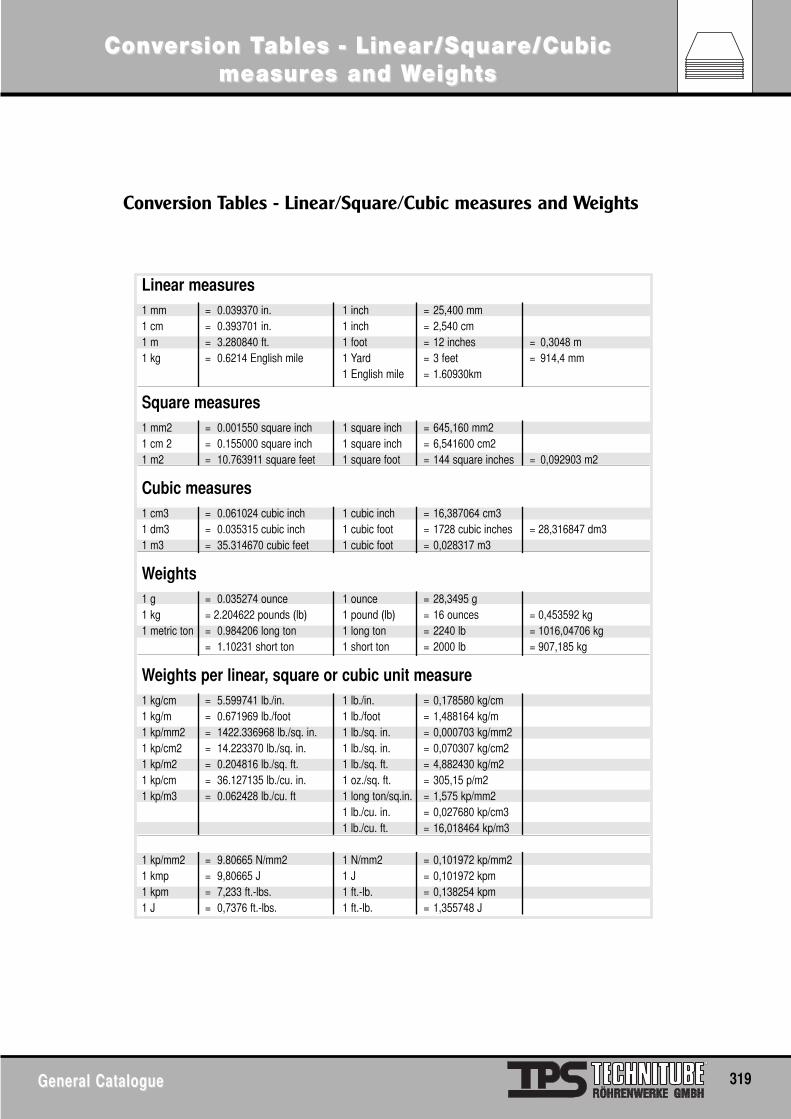
General CatalogueGeneral Catalogue 319
ConConvverersion Tsion Tables - Linear/Sqables - Linear/Squaruare/Cubice/Cubicmeasurmeasures and Wes and Weightseights
Linear measures1 mm = 0.039370 in. 1 inch = 25,400 mm1 cm = 0.393701 in. 1 inch = 2,540 cm1 m = 3.280840 ft. 1 foot = 12 inches = 0,3048 m1 kg = 0.6214 English mile 1 Yard = 3 feet = 914,4 mm
1 English mile = 1.60930km
Square measures1 mm2 = 0.001550 square inch 1 square inch = 645,160 mm21 cm 2 = 0.155000 square inch 1 square inch = 6,541600 cm21 m2 = 10.763911 square feet 1 square foot = 144 square inches = 0,092903 m2
Cubic measures1 cm3 = 0.061024 cubic inch 1 cubic inch = 16,387064 cm31 dm3 = 0.035315 cubic inch 1 cubic foot = 1728 cubic inches = 28,316847 dm31 m3 = 35.314670 cubic feet 1 cubic foot = 0,028317 m3
Weights1 g = 0.035274 ounce 1 ounce = 28,3495 g1 kg = 2.204622 pounds (lb) 1 pound (lb) = 16 ounces = 0,453592 kg1 metric ton = 0.984206 long ton 1 long ton = 2240 lb = 1016,04706 kg
= 1.10231 short ton 1 short ton = 2000 lb = 907,185 kg
Weights per linear, square or cubic unit measure1 kg/cm = 5.599741 lb./in. 1 lb./in. = 0,178580 kg/cm1 kg/m = 0.671969 lb./foot 1 lb./foot = 1,488164 kg/m1 kp/mm2 = 1422.336968 lb./sq. in. 1 lb./sq. in. = 0,000703 kg/mm21 kp/cm2 = 14.223370 lb./sq. in. 1 lb./sq. in. = 0,070307 kg/cm21 kp/m2 = 0.204816 lb./sq. ft. 1 lb./sq. ft. = 4,882430 kg/m21 kp/cm = 36.127135 lb./cu. in. 1 oz./sq. ft. = 305,15 p/m21 kp/m3 = 0.062428 lb./cu. ft 1 long ton/sq.in. = 1,575 kp/mm2
1 lb./cu. in. = 0,027680 kp/cm31 lb./cu. ft. = 16,018464 kp/m3
1 kp/mm2 = 9.80665 N/mm2 1 N/mm2 = 0,101972 kp/mm21 kmp = 9,80665 J 1 J = 0,101972 kpm1 kpm = 7,233 ft.-lbs. 1 ft.-lb. = 0,138254 kpm1 J = 0,7376 ft.-lbs. 1 ft.-lb. = 1,355748 J
Conversion Tables - Linear/Square/Cubic measures and Weights
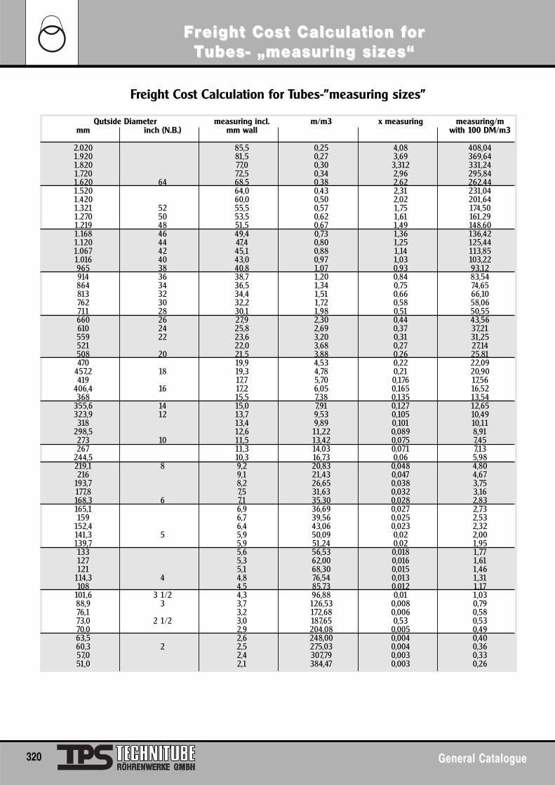
Qutside Diameter measuring incl. m/m3 x measuring measuring/mmm inch (N.B.) mm wall with 100 DM/m3
2.020 85,5 0,25 4,08 408,041.920 81,5 0,27 3,69 369,641.820 77,0 0,30 3,312 331,241.720 72,5 0,34 2,96 295,841.620 64 68,5 0,38 2,62 262,441.520 64,0 0,43 2,31 231,041.420 60,0 0,50 2,02 201,641.321 52 55,5 0,57 1,75 174,501.270 50 53,5 0,62 1,61 161,291.219 48 51,5 0,67 1,49 148,601.168 46 49,4 0,73 1,36 136,421.120 44 47,4 0,80 1,25 125,441.067 42 45,1 0,88 1,14 113,851.016 40 43,0 0,97 1,03 103,22965 38 40,8 1,07 0,93 93,12914 36 38,7 1,20 0,84 83,54864 34 36,5 1,34 0,75 74,65813 32 34,4 1,51 0,66 66,10762 30 32,2 1,72 0,58 58,06711 28 30,1 1,98 0,51 50,55660 26 27,9 2,30 0,44 43,56610 24 25,8 2,69 0,37 37,21559 22 23,6 3,20 0,31 31,25521 22,0 3,68 0,27 27,14508 20 21,5 3,88 0,26 25,81470 19,9 4,53 0,22 22,09
457,2 18 19,3 4,78 0,21 20,90419 17,7 5,70 0,176 17,56
406,4 16 17,2 6,05 0,165 16,52368 15,5 7,38 0,135 13,54
355,6 14 15,0 7,91 0,127 12,65323,9 12 13,7 9,53 0,105 10,49318 13,4 9,89 0,101 10,11
298,5 12,6 11,22 0,089 8,91273 10 11,5 13,42 0,075 7,45267 11,3 14,03 0,071 7,13
244,5 10,3 16,73 0,06 5,98219,1 8 9,2 20,83 0,048 4,80216 9,1 21,43 0,047 4,67
193,7 8,2 26,65 0,038 3,75177,8 7,5 31,63 0,032 3,16168,3 6 7,1 35,30 0,028 2,83165,1 6,9 36,69 0,027 2,73159 6,7 39,56 0,025 2,53
152,4 6,4 43,06 0,023 2,32141,3 5 5,9 50,09 0,02 2,00139,7 5,9 51,24 0,02 1,95133 5,6 56,53 0,018 1,77127 5,3 62,00 0,016 1,61121 5,1 68,30 0,015 1,46
114,3 4 4,8 76,54 0,013 1,31108 4,5 85,73 0,012 1,17
101,6 3 1/2 4,3 96,88 0,01 1,0388,9 3 3,7 126,53 0,008 0,7976,1 3,2 172,68 0,006 0,5873,0 2 1/2 3,0 187,65 0,53 0,5370,0 2,9 204,08 0,005 0,4963,5 2,6 248,00 0,004 0,4060,3 2 2,5 275,03 0,004 0,3657,0 2,4 307,79 0,003 0,3351,0 2,1 384,47 0,003 0,26
Freight Cost Calculation for Tubes-”measuring sizes”
320 General CatalogueGeneral Catalogue
FFrreight Coseight Cost Calculation ft Calculation fororTTubes- „measurubes- „measuring sizes“ing sizes“
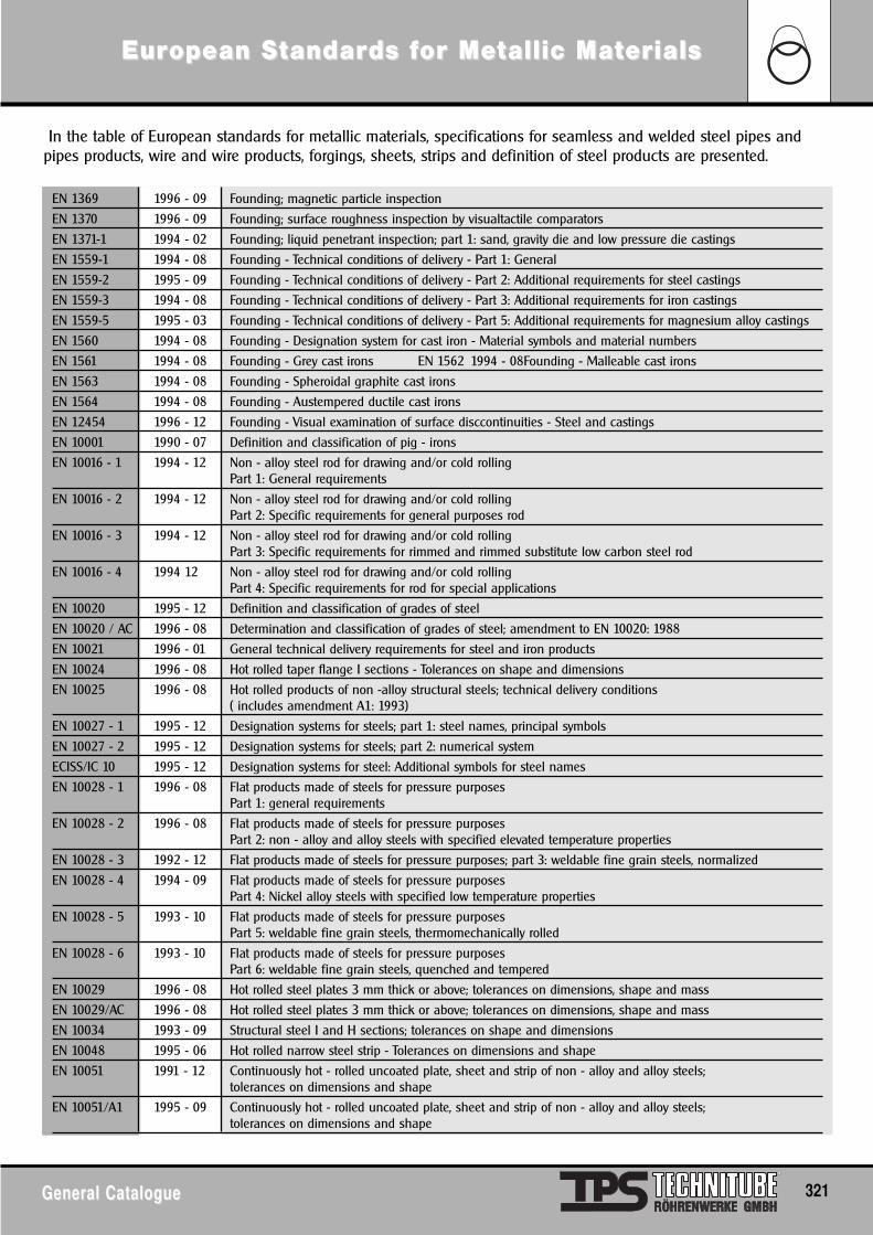
General CatalogueGeneral Catalogue 321
EurEuropean Sopean Sttandarandards fds for Meor Mettallic Matallic Matererialsials
In the table of European standards for metallic materials, specifications for seamless and welded steel pipes andpipes products, wire and wire products, forgings, sheets, strips and definition of steel products are presented.
EN 1369 1996 - 09 Founding; magnetic particle inspection
EN 1370 1996 - 09 Founding; surface roughness inspection by visualtactile comparators
EN 1371-1 1994 - 02 Founding; liquid penetrant inspection; part 1: sand, gravity die and low pressure die castings
EN 1559-1 1994 - 08 Founding - Technical conditions of delivery - Part 1: General
EN 1559-2 1995 - 09 Founding - Technical conditions of delivery - Part 2: Additional requirements for steel castings
EN 1559-3 1994 - 08 Founding - Technical conditions of delivery - Part 3: Additional requirements for iron castings
EN 1559-5 1995 - 03 Founding - Technical conditions of delivery - Part 5: Additional requirements for magnesium alloy castings
EN 1560 1994 - 08 Founding - Designation system for cast iron - Material symbols and material numbers
EN 1561 1994 - 08 Founding - Grey cast irons EN 1562 1994 - 08Founding - Malleable cast irons
EN 1563 1994 - 08 Founding - Spheroidal graphite cast irons
EN 1564 1994 - 08 Founding - Austempered ductile cast irons
EN 12454 1996 - 12 Founding - Visual examination of surface disccontinuities - Steel and castings
EN 10001 1990 - 07 Definition and classification of pig - irons
EN 10016 - 1 1994 - 12 Non - alloy steel rod for drawing and/or cold rolling Part 1: General requirements
EN 10016 - 2 1994 - 12 Non - alloy steel rod for drawing and/or cold rollingPart 2: Specific requirements for general purposes rod
EN 10016 - 3 1994 - 12 Non - alloy steel rod for drawing and/or cold rolling Part 3: Specific requirements for rimmed and rimmed substitute low carbon steel rod
EN 10016 - 4 1994 12 Non - alloy steel rod for drawing and/or cold rollingPart 4: Specific requirements for rod for special applications
EN 10020 1995 - 12 Definition and classification of grades of steel
EN 10020 / AC 1996 - 08 Determination and classification of grades of steel; amendment to EN 10020: 1988
EN 10021 1996 - 01 General technical delivery requirements for steel and iron products
EN 10024 1996 - 08 Hot rolled taper flange I sections - Tolerances on shape and dimensions
EN 10025 1996 - 08 Hot rolled products of non -alloy structural steels; technical delivery conditions ( includes amendment A1: 1993)
EN 10027 - 1 1995 - 12 Designation systems for steels; part 1: steel names, principal symbols
EN 10027 - 2 1995 - 12 Designation systems for steels; part 2: numerical system
ECISS/IC 10 1995 - 12 Designation systems for steel: Additional symbols for steel names
EN 10028 - 1 1996 - 08 Flat products made of steels for pressure purposesPart 1: general requirements
EN 10028 - 2 1996 - 08 Flat products made of steels for pressure purposesPart 2: non - alloy and alloy steels with specified elevated temperature properties
EN 10028 - 3 1992 - 12 Flat products made of steels for pressure purposes; part 3: weldable fine grain steels, normalized
EN 10028 - 4 1994 - 09 Flat products made of steels for pressure purposesPart 4: Nickel alloy steels with specified low temperature properties
EN 10028 - 5 1993 - 10 Flat products made of steels for pressure purposesPart 5: weldable fine grain steels, thermomechanically rolled
EN 10028 - 6 1993 - 10 Flat products made of steels for pressure purposesPart 6: weldable fine grain steels, quenched and tempered
EN 10029 1996 - 08 Hot rolled steel plates 3 mm thick or above; tolerances on dimensions, shape and mass
EN 10029/AC 1996 - 08 Hot rolled steel plates 3 mm thick or above; tolerances on dimensions, shape and mass
EN 10034 1993 - 09 Structural steel I and H sections; tolerances on shape and dimensions
EN 10048 1995 - 06 Hot rolled narrow steel strip - Tolerances on dimensions and shape
EN 10051 1991 - 12 Continuously hot - rolled uncoated plate, sheet and strip of non - alloy and alloy steels; tolerances on dimensions and shape
EN 10051/A1 1995 - 09 Continuously hot - rolled uncoated plate, sheet and strip of non - alloy and alloy steels; tolerances on dimensions and shape
EN 10052 1996 - 08 Vocabulary of heat treatment terms for ferrous products
EN 10055 1995 - 11 Hot rolled steel equal flange tees with radiused root and toesDimensions and tolerances on shape and dimensions
EN 10056 1991 - 03 Structural steel equal and unequal leg angles; tolerances on shape and dimensions
EN 10056 - 1 1994 - 11 Structural steel equal and unequal leg angles - Part 1: Dimensions
EN 10056 - 2 1993 - 09 Structural steel equal and unequal leg angles; part 2: tolerances on shape and dimensions
EN 10067 1992 - 08 Hot rolled bulb flats; dimensions and tolerances on shape and dimensions
EN 10079 1995 - 12 Definition of steel products
ENV 10080 1995 - 04 Steel for the reinforcement of concrete - Weldable ribbed reinforcing steel B 500Technical delivery conditions for bars, coils and welded fabric
EN 10083 - 1 1996 - 08 Quenched and tempered steels; part 1: technical delivery conditions for special steels
EN 10083 - 1/A1 1995 - 03 Quenched and tempered steels - Part 1: Technical delivery conditions for special steels
EN 10083 - 2 1991 - 02 Quenched and tempered steels - Part 2: Technical delivery conditions for unalloyed quality steels
EN 10083 - 2/A1 1995 - 03 Quenched and tempered steels - Part 2: Technical delivery conditions for unalloyed quality steels
EN 10083 - 3 1995 - 09 Quenched and tempered steels - Part 3: Technical delivery conditions for boron steels
EN 10084EN 10087 1995 - Case hardening steels - Technical delivery conditionsFree - cutting steels -021995 - 04 Technical delivery conditions for semi - finished products, hot rolled bars and rods
EN 10088 - 1 1995 - 04 Stainless steels - Part 1: List of stainless steels
EN 10088 - 2 1995 - 04 Stainless steels - Part 2: Technical delivery conditions for sheet/plate and strip for general purposes
EN 10088 - 3 1995 - 04 Stainless steels - Part 3: Technical delivery conditions for semi finished products, bars, rods and sections for general purposes
EN 10095 1996 - 02 Heat - resisting steels and alloys
EN 10106 1995 - 12 Cold rolled non - oriented electrical steel sheet and strip delivered in fully processed state
EN 10107 1995 - 12 Grain - oriented electrical steel sheet and strip delivered in fully processed state
EN 10111 1993 - 06 Continuously hot-rolled low carbon steel sheet and strip for cold bending; technical delivery conditions
EN 10113 - 1 1993 - 03 Hot-rolled products in weldable fine grain structural steelsPart 1: general delivery conditions
EN 10113 - 2 1993 - 03 Hot-rolled products in weldable fine grain structural steelsPart 2: delivery conditions for normalized/normalized rolled steels
EN 10113 - 3 1993 - 03 Hot-rolled products in weldable fine grain structural steelsPart 3: delivery conditions for thermomechanical rolled steels
EN 10120 1994 - 06 Steel sheet and strip for welded gas cylinders
EN 10126 1995 - 12 Cold rolled electrical non-alloyed steel sheet and strip delivered in semi-processed state
EN 10130 1991 - 03 Cold rolled low carbon steel flat products for cold forming; technical delivery conditions
EN 10130/A1 1995 - 03 Cold rolled low carbon steel flat products for cold forming; -Technical delivery conditions
EN 10137 - 2 1995 - 09 Plates and wide flats made of high yield strength structural steels in the quenched and tempered or precipitation hardened conditions - Part 2: Delivery conditions for quenched and tempered steels
EN 10131 1991 - 11 Cold rolled uncoated low carbon high yield strength steel flat products for cold forming;tolerances on dimensions and shape
EN 10137 - 1 1995 - 09 Plates and wide flats made of high yield strength structural steels in the quenched and tempered or precipitation hardened conditions - Part 1: General delivery conditions
EN 10137 - 2 1995 - 09 Plates and wide flats made of high yield strength structural steels in the quenched and tempered or precipitation hardened conditions - Part 2: Delivery conditions for quenched and tempered steels
EN 10137 - 3 1995 - 09 Plates and wide flats made of high yield strength structural steels in the quenched and tempered or precipitation hardened conditions - Part 3: Delivery conditions for precipitation hardened steels
EN 10138 - 1 1991 - 11 Prestressing steels; part 1: general requirements
EN 10138 - 2 1991 - 11 Prestressing steels; part 2: stress relieved cold drawn wire
EN 10138 - 3 1991 - 11 Prestressing steels; part 3: strand
EN 10138 - 4 1991 - 11 Prestressing steels; part 4: hot rolled and processed bars
EN 10138 - 5 1991 - 11 Prestressing steels; part 5: quenched and tempered wire
EN 10139 1992 - 10 Cold rolled uncoated mild steel narrow strip for cold forming; technical delivery conditions
EurEuropean Sopean Sttandarandards fds for Meor Mettallic Matallic Matererialsials
322 General CatalogueGeneral Catalogue
EurEuropean Sopean Sttandarandards fds for Meor Mettallic Matallic Matererialsials
General CatalogueGeneral Catalogue 323
EN 10140 1992 - 10 Cold rolled narrow steel strip; tolerances on dimensions and shape
EN 10142 1996 - 08 Continously hot-dip zinc coated low carbon steel sheet and strip for cold forming; technical delivery conditions
EN 10143 1993 - 01 Continously hot-dip metal coated steel sheet and strip; tolerances on dimensions and shape
EN 10147 1991 - 11 Continously hot-dip zinc coated unalloyed structural steel sheet and strip; technical delivery conditions
EN 10147/A1 1995 - 06 Continously hot-dip zinc coated structural steel strip and sheet - Technical delivery conditions; Amendment A1
EN 10149 - 1 1995 - 09 Hot rolled flat products made of high yield strength steels for cold formingPart 1: General delivery conditions
EN 10149 - 2 1995 - 09 Hot rolled flat products made of high yield strength steels for cold formingPart 2: Delivery conditions for thermomechanically rolled steels
EN 10149 - 3 1995 - 09 Hot rolled flat products made of high yield strength steels for cold formingPart 3: Delivery conditions for normalized or normalized rolled steels
EN 10152 1993 - 10 Electrolytically zinc coated cold rolled steel flat products; technical delivery conditions
EN 10154 1995 - 10 Continuously hot-dip aluminium-silicon (AS) coated steel strip and sheet - Technical delivery conditions
EN 10155 1993 - 06 Structural steels with improved atmospheric corrosion resistance; technical delivery conditions
EN 10163 - 1 1991 - 08 Delivery requirements for surface condition of hot rolled steel plates, wide flats and sectionsPart 1: general requirements
EN 10163 - 2 1991 - 08 Delivery requirements for surface condition of hot rolled steel plates, wide flats and sectionsPart 2: plate and wide flats
EN 10163 - 3 1991 - 08 Delivery requirements for surface condition of hot rolled steel plates, wide flats and sectionsPart 3: sections
EN 10163 - 4 1991 - 09 Delivery requirements for surface quality of hot rolled steel products; part 4: round bars and wire rod
EN 10164 1993 - 06 Steel products with improved deformation properties perpendicular of the product; technical delivery conditions
EN 10165 1995 - 12 Cold rolled electrical alloyed steel sheet and strip delivered in semi - processed state
EN 10169 - 1 1995 - 08 Continuously organic coated steel flat productsPart 1: General information (definitions, materials, tolerances, test methods )
EN 10169 - 2 1995 - 10 Continuously organic coated (coil coated) steel flat productsPart 2: Products for building exterior applications
EN 10173 1987 - 03 Double cold reduced electrolytic chromium/chromium oxide coated steel; coil for subsequent cutting into sheets
EN 10202 1996 - 08 Cold reduced electrolytic chromium/chromium oxide coated steel
EN 10203 1991 - 08 Cold reduced electrolytic tinplate
EN 10204 1996 - 01 Metallic products; types of inspection documents
EN 10204/A1 1996 - 01 Metallic products-Types of inspection documents; Amendment A1
EN 10205 1991 - 11 Cold reduced blackplate in coil form for the production of tinplate or electrolytic chromium/chromium oxide coated steel
EN 10207 1991 - 11 Steels for simple pressure vessels; technical delivery requirements for plates, strips and bars
EN 10208 - 1 1992 - 11 Steel pipes for pipe lines for combustible fluids; technical delivery conditionsPart 1: pipes of requirement class A
EN 10208 - 2 1996 - 09 Steel pipes for pipe lines for combustible fluids; technical delivery conditions;Part 2: pipes of requirement class B
EN 10209 1996 - 10 Cold rolled low carbon steel flat products for vitreous enamelling - Technical delivery conditions
EN 10210 - 1 1994 - 03 Hot finished structural hollow sections of non - alloy and fine grain structural steelsPart 1: technical delivery requirements
EN 10210 - 2 1992 - 09 Hot finished structural hollow sections of non - alloy and fine grain structural steelsPart 2: tolerances, dimension and sectional properties
EN 10213 - 1 1995 - 12 Technical delivery conditions for steel castings for pressure purposes - Part 1: General
EN 10213 - 2 1995 - 12 Technical delivery conditions for steel castings for pressure purposes Part 2: Steel grades for use at room temperature and elevated temperatures
EN 10213 - 3 1995 - 12 Technical delivery conditions for steel castings for pressure purposes Part 3: Steel grades for use at low temperatures
EN 10213 - 4 1995 - 12 Technical delivery conditions for steel castings for pressure purposesPart 4: Austenitic and austenitic - ferritic steel grades
EN 10214 1995 - 02 Continuously hot-dip zinc-aluminium (ZA) coated steel strip and sheet - Technical delivery conditions
EN 10215 1995 - 02 Continuously hot-dip aluminium-zinc (AZ) coated steel strip and sheet - Technical delivery conditions
EN 10216-1 1995 - 11 Seamless steel tubes for pressure purposes; technical delivery conditionsPart 1: non-alloy steel with specified room temperature properties
EN 10217 - 1 1991 - 02 Welded steel tubes for pressure purposes; technical delivery conditionsPart 1: non -alloy steel with specified room temperature properties
EN 10218 - 1 1994 - Steel wire and wire products; generalEN 10218 - 2 031995 - 11 Part 1: test methodsSteel wire and wire products; general; part 2: wire dimensions and tolerances
EN 10219 - 1 1992 - 09 Cold formed structural hollow sections of non-alloy and fine grain structural steelsPart 1: technical delivery requirements
EN 10219 - 2 1992 - 09 Cold formed structural hollow sections of non-alloy and fine grain structural steelsPart 2: tolerances, dimensions and sectional properties
ENV 10220 1993 - 11 Seamless and welded steel tubes; dimensions and masses per unit length
EN 10221 1995 - 11 Surface quality classes for hot-rolled bars and rods - Technical delivery conditions
EN 10222 - 1 1994 - 06 Steel forgings for pressure purposes Part 1: General requirements for open die forgings
EN 10222 - 3 1994 - 06 Steel forgings for pressure purposesPart 3: Ferritic and martensitic steels with elevated temperature properties
EN 10222 - 4 1994 - 06 Steel forgings for pressure purposesPart 4: Nickel steels with specified low temperature properties
EN 10222 - 5 1994 - 06 Steel forgings for pressure purposes Part 5: Fine grain steels with high proof stress
EN 10222 - 6 1994 - 06 Steel forgings for pressure purposes Part 6: Austenitic, martensitic and austenitic-ferritic stainless steels
EN 10223 - 1 1993 - 02 Steel wire and wire products for fencesPart 1: zinc and zinc-alloy coated steel barbed wire
EN 10223 - 2 1993 - 04 Steel wire and wire products for fencesPart 2: hexagonal steel wire netting for agricultural, insulation, and fencing purposes
EN 10223 - 3 1993 - 04 Steel wire and wire products for fences Part 3: hexagonal steel wire netting for engineering purposes
EN 10223 - 4 1994 -10 Steel wire and wire products for fences Part 4: Steel wire welded mesh fencing
EN 10223 - 5 1994 -10 Steel wire and wire products for fences Part 5: Steel wire woven hinged joint and knotted joint stock fencing
EN 10223 - 6 1994 -10 Steel wire and wire products for fencesPart 6: Steel wire chain link fencing
EN 10224 1995 - 05 Steel tubes and fittings for the conveyance of aqueous liquids including water for human consumption
EN 10225 1994 - 10 Weldable structural steels for fixed offshore structures
EN 10226 - 1 1995 -11 Pipe threads where pressure tight joints are made on the threadsPart 1: Designation, dimensions and tolerances
EN 10229 1995 - 08 Evaluation of resistance of steel products to hydrogen induced cracking (HIC)
EN 10230 1993 - 02 Steel wire and wire products; common, special and loose feed stock steel wire machine nails
EN 10238 1995 - 12 Automatically blast cleaned and primed steel products
EN 10240 1994 - 06 Internal and/or external protective coatings for steel tubes - Specification for hot dip galvanized coatings
EN 10241 1994 - 06 Threaded steel fittings
EN 10242 1994 - 11 Threaded pipe fitting in malleable cast iron
EN 10243 - 1 1995 - 08 Steel drop and press forgings - Tolerances on dimensions
EN 10243 - 2 1995 - 08 Steel upset forgings made on horizontal forging machines -Tolerances on dimensions
EN 10244 - 1 1995 - 01 Steel wire and wire products - Non-ferrous metallic coatings on steel wire Part 1: General principles
EurEuropean Sopean Sttandarandards fds for Meor Mettallic Matallic Matererialsials
324 General CatalogueGeneral Catalogue
EurEuropean Sopean Sttandarandards fds for Meor Mettallic Matallic Matererialsials
General CatalogueGeneral Catalogue 325
EN 10244 - 2 1995 - 01 Steel wire and wire products - Non-ferrous metallic coatings on steel wirePart 2: Zinc or zinc alloy coatings on steel wire
EN 10244 - 3 1995 - 01 Steel wire and wire products - Non-ferrous metallic coatings on steel wirePart 3: Aluminium coatings
EN 10244 - 4 1995 - 01 Steel wire and wire products - Non-ferrous metallic coatings on steel wirePart 4: Tin coatings
EN 10244 - 5 1995 - 01 Steel wire and wire products - Non-ferrous metallic coatings on steel wirePart 5: Nickel coatings
EN 10244 - 6 1995 - 01 Steel wire and wire products - Non-ferrous metallic coatings on steel wirePart 6: Copper, bronze or brass coatings
EN 10245 - 1 1995 - 01 Steel wire and wire products - Organic coatings on wire -Part 1: General rules
EN 10245 - 2 1995 - 01 Steel wire and wire products - Organic coatings on wire -Part 2: PVC coated wire
EN 10245 - 3 1995 - 01 Steel wire and wire products - Organic coatings on wire -Part 3: PE coated wire
EN 10248 - 1 1995 - 06 Hot rolled sheet piling of non alloy steels - Part 1: Technical delivery conditions
EN 10248 - 2 1995 - 06 Hot rolled sheet piling of non alloy steels - Part 2: Tolerances on shape and dimensions
EN 10249 - 1 1995 - 06 Cold formed sheet piling of non alloy steels - Part 1: Technical delivery conditions
EN 10249 - 2 1995 - 06 Cold formed sheet piling of non alloy steels - Part 2: Tolerances on shape and dimensions
EN 10253 - 1 1994 - 01 Butt; welding pipe fittings wrought carbon steel without specific inspection requirements
EN 10254 1995 - 08 Steel closed die forgings - General technical delivery conditions
EN 10255 1996 - 01 Non-alloy steel tubes suitable for welding or threading
EN 10257 - 1 1994 - 11 Zinc or zinc alloy coated low carbon steel wire for armouring cables - Part 1: Land cables
EN 10257 - 2 1994 - 11 Zinc or zinc alloy coated low carbon steel wire for armouring cables - Part 2: Submarine cables
EN 10267 1995 - 08 Ferritic-pearlitic engineering steels for precipitation hardening from hot-working temperatures
EN 10268 1995 - 10 Cold-rolled flat products made of high field strength steels for cold forming - General delivery conditions
EN 10271 1996 - 03 Electrolyticaly zinc-nickel (ZN) coated cold roled steel flat products - Tehnical delvery conditions
EN 10283 1996 - 04 Corrosion resistant steel casting
EN 10284 1996 - 04 Malleable cast iron fittings with commresion ends for plastics piping system
EN 10285 1996 - 12 Steel tubes and fittings for on and offshore pipelinesExternal three layer extruded polyethylene based coating
EN 10286 1996 - 12 Steel tubes and fittings for on and offshore pipelines External three layer extruded polypropylene based coatings
EN 10287 1996 - 12 Steel tubes and fittings for on and offshore pipelines - External fused polyethylene based coatings
EN 10288 1997 - 01 Steel tubes and fittings for on and offshore pipelinesExternal two layer extruded polyethylene based coatings
EN 20049 - 01 1991 - 12 Melleable cast iron threaded pipe fittings;Part 1: fittings with parallel internal and taper external threads in accordance with ISO 7-1
EN 29658 1991 - 12 Steel; determination of aluminium content; flame atomic absorption spectrometric method (ISO 9658 :1990)
EN ISO 945 1994 - 07 Cast iron - Designation of microstructure of graphite (ISO 945 : 1975)
EN ISO 1127 1995 - 10 Stainless steel tubes - Dimensions, tolerances and conventional masses per unit length
EN ISO 3785 1995 - 01 Steel - Designation of test piece axes (ISO 3785 : 1976)
EN ISO 8434 - 1 1995 - 05 Metallic tube connections for fluid power and general use Part 1: 24 < Grad > compression fittings (ISO 8434-1:1994)
EN ISO 10380 1995 - 05 Corrugated flexible metallic hose and hose assemblies (ISO 10380 : 1994)
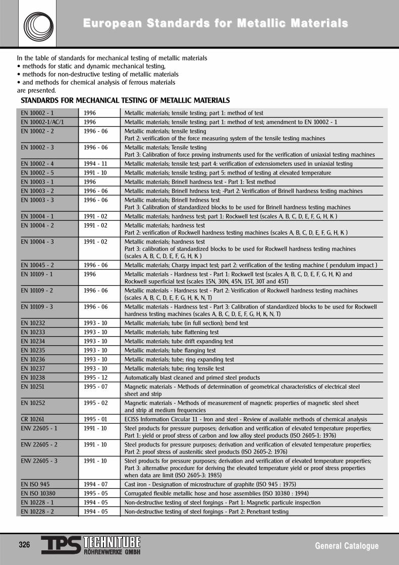
In the table of standards for mechanical testing of metallic materials• methods for static and dynamic mechanical testing,• methods for non-destructive testing of metallic materials• and methods for chemical analysis of ferrous materialsare presented.
EN 10002 - 1 1996 Metallic materials; tensile testing; part 1: method of testEN 10002-1/AC/1 1996 Metallic materials; tensile testing; part 1: method of test; amendment to EN 10002 - 1EN 10002 - 2 1996 - 06 Metallic materials; tensile testing
Part 2: verification of the force measuring system of the tensile testing machinesEN 10002 - 3 1996 - 06 Metallic materials; Tensile testing
Part 3: Calibration of force proving instruments used for the verification of uniaxial testing machinesEN 10002 - 4 1994 - 11 Metallic materials; tensile test; part 4: verification of extensiometers used in uniaxial testingEN 10002 - 5 1991 - 10 Metallic materials; tensile testing; part 5: method of testing at elevated temperatureEN 10003 - 1 1996 Metallic materials; Brinell hardness test - Part 1: Test methodEN 10003 - 2 1996 - 06 Metallic materials; Brinell hrdness test; -Part 2: Verification of Brinell hardness testing machinesEN 10003 - 3 1996 - 06 Metallic materials; Brinell hrdness test
Part 3: Calibration of standardized blocks to be used for Brinell hardness testing machinesEN 10004 - 1 1991 - 02 Metallic materials; hardness test; part 1: Rockwell test (scales A, B, C, D, E, F, G, H, K )EN 10004 - 2 1991 - 02 Metallic materials; hardness test
Part 2: verification of Rockwell hardness testing machines (scales A, B, C, D, E, F, G, H, K )EN 10004 - 3 1991 - 02 Metallic materials; hardness test
Part 3: calibration of standardized blocks to be used for Rockwell hardness testing machines (scales A, B, C, D, E, F, G, H, K )
EN 10045 - 2 1996 - 06 Metallic materials; Charpy impact test; part 2: verification of the testing machine ( pendulum impact )EN 10109 - 1 1996 Metallic materials - Hardness test - Part 1: Rockwell test (scales A, B, C, D, E, F, G, H, K) and
Rockwell superficial test (scales 15N, 30N, 45N, 15T, 30T and 45T)EN 10109 - 2 1996 - 06 Metallic materials - Hardness test - Part 2: Verification of Rockwell hardness testing machines
(scales A, B, C, D, E, F, G, H, K, N, T)EN 10109 - 3 1996 - 06 Metallic materials - Hardness test - Part 3: Calibration of standardized blocks to be used for Rockwell
hardness testing machines (scales A, B, C, D, E, F, G, H, K, N, T)EN 10232 1993 - 10 Metallic materials; tube (in full section); bend testEN 10233 1993 - 10 Metallic materials; tube flattening testEN 10234 1993 - 10 Metallic materials; tube drift expanding testEN 10235 1993 - 10 Metallic materials; tube flanging testEN 10236 1993 - 10 Metallic materials; tube; ring expanding testEN 10237 1993 - 10 Metallic materials; tube; ring tensile testEN 10238 1995 - 12 Automatically blast cleaned and primed steel productsEN 10251 1995 - 07 Magnetic materials - Methods of determination of geometrical characteristics of electrical steel
sheet and stripEN 10252 1995 - 02 Magnetic materials - Methods of measurement of magnetic properties of magnetic steel sheet
and strip at medium frequenciesCR 10261 1995 - 01 ECISS Information Circular 11 - Iron and steel - Review of available methods of chemical analysisENV 22605 - 1 1991 - 10 Steel products for pressure purposes; derivation and verification of elevated temperature properties;
Part 1: yield or proof stress of carbon and low alloy steel products (ISO 2605-1: 1976)ENV 22605 - 2 1991 - 10 Steel products for pressure purposes; derivation and verification of elevated temperature properties;
Part 2: proof stress of austenitic steel products (ISO 2605-2: 1976)ENV 22605 - 3 1991 - 10 Steel products for pressure purposes; derivation and verification of elevated temperature properties;
Part 3: alternative procedure for deriving the elevated temperature yield or proof stress properties when data are limit (ISO 2605-3: 1985)
EN ISO 945 1994 - 07 Cast iron - Designation of microstructure of graphite (ISO 945 : 1975)EN ISO 10380 1995 - 05 Corrugated flexible metallic hose and hose assemblies (ISO 10380 : 1994)EN 10228 - 1 1994 - 05 Non-destructive testing of steel forgings - Part 1: Magnetic particule inspectionEN 10228 - 2 1994 - 05 Non-destructive testing of steel forgings - Part 2: Penetrant testing
STANDARDS FOR MECHANICAL TESTING OF METALLIC MATERIALS
EurEuropean Sopean Sttandarandards fds for Meor Mettallic Matallic Matererialsials
326 General CatalogueGeneral Catalogue
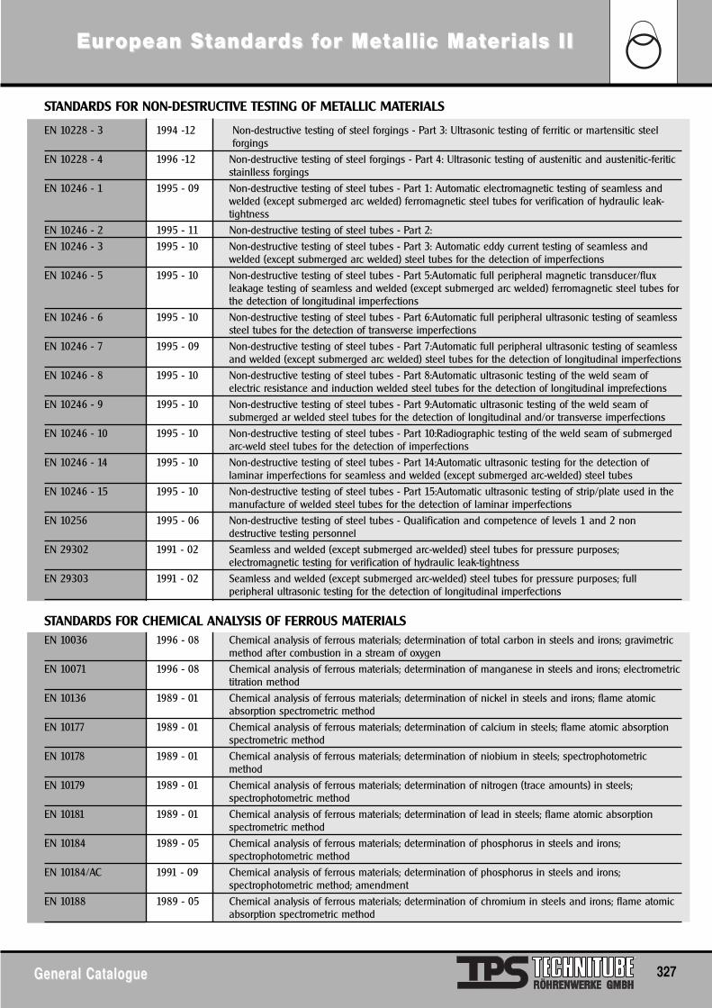
EurEuropean Sopean Sttandarandards fds for Meor Mettallic Matallic Matererials IIials II
General CatalogueGeneral Catalogue 327
EN 10228 - 3 1994 -12 Non-destructive testing of steel forgings - Part 3: Ultrasonic testing of ferritic or martensitic steelforgings
EN 10228 - 4 1996 -12 Non-destructive testing of steel forgings - Part 4: Ultrasonic testing of austenitic and austenitic-feriticstainlless forgings
EN 10246 - 1 1995 - 09 Non-destructive testing of steel tubes - Part 1: Automatic electromagnetic testing of seamless andwelded (except submerged arc welded) ferromagnetic steel tubes for verification of hydraulic leak-tightness
EN 10246 - 2 1995 - 11 Non-destructive testing of steel tubes - Part 2:EN 10246 - 3 1995 - 10 Non-destructive testing of steel tubes - Part 3: Automatic eddy current testing of seamless and
welded (except submerged arc welded) steel tubes for the detection of imperfectionsEN 10246 - 5 1995 - 10 Non-destructive testing of steel tubes - Part 5:Automatic full peripheral magnetic transducer/flux
leakage testing of seamless and welded (except submerged arc welded) ferromagnetic steel tubes forthe detection of longitudinal imperfections
EN 10246 - 6 1995 - 10 Non-destructive testing of steel tubes - Part 6:Automatic full peripheral ultrasonic testing of seamlesssteel tubes for the detection of transverse imperfections
EN 10246 - 7 1995 - 09 Non-destructive testing of steel tubes - Part 7:Automatic full peripheral ultrasonic testing of seamlessand welded (except submerged arc welded) steel tubes for the detection of longitudinal imperfections
EN 10246 - 8 1995 - 10 Non-destructive testing of steel tubes - Part 8:Automatic ultrasonic testing of the weld seam ofelectric resistance and induction welded steel tubes for the detection of longitudinal imprefections
EN 10246 - 9 1995 - 10 Non-destructive testing of steel tubes - Part 9:Automatic ultrasonic testing of the weld seam ofsubmerged ar welded steel tubes for the detection of longitudinal and/or transverse imperfections
EN 10246 - 10 1995 - 10 Non-destructive testing of steel tubes - Part 10:Radiographic testing of the weld seam of submergedarc-weld steel tubes for the detection of imperfections
EN 10246 - 14 1995 - 10 Non-destructive testing of steel tubes - Part 14:Automatic ultrasonic testing for the detection oflaminar imperfections for seamless and welded (except submerged arc-welded) steel tubes
EN 10246 - 15 1995 - 10 Non-destructive testing of steel tubes - Part 15:Automatic ultrasonic testing of strip/plate used in themanufacture of welded steel tubes for the detection of laminar imperfections
EN 10256 1995 - 06 Non-destructive testing of steel tubes - Qualification and competence of levels 1 and 2 nondestructive testing personnel
EN 29302 1991 - 02 Seamless and welded (except submerged arc-welded) steel tubes for pressure purposes;electromagnetic testing for verification of hydraulic leak-tightness
EN 29303 1991 - 02 Seamless and welded (except submerged arc-welded) steel tubes for pressure purposes; fullperipheral ultrasonic testing for the detection of longitudinal imperfections
EN 10036 1996 - 08 Chemical analysis of ferrous materials; determination of total carbon in steels and irons; gravimetricmethod after combustion in a stream of oxygen
EN 10071 1996 - 08 Chemical analysis of ferrous materials; determination of manganese in steels and irons; electrometrictitration method
EN 10136 1989 - 01 Chemical analysis of ferrous materials; determination of nickel in steels and irons; flame atomicabsorption spectrometric method
EN 10177 1989 - 01 Chemical analysis of ferrous materials; determination of calcium in steels; flame atomic absorptionspectrometric method
EN 10178 1989 - 01 Chemical analysis of ferrous materials; determination of niobium in steels; spectrophotometricmethod
EN 10179 1989 - 01 Chemical analysis of ferrous materials; determination of nitrogen (trace amounts) in steels;spectrophotometric method
EN 10181 1989 - 01 Chemical analysis of ferrous materials; determination of lead in steels; flame atomic absorptionspectrometric method
EN 10184 1989 - 05 Chemical analysis of ferrous materials; determination of phosphorus in steels and irons;spectrophotometric method
EN 10184/AC 1991 - 09 Chemical analysis of ferrous materials; determination of phosphorus in steels and irons;spectrophotometric method; amendment
EN 10188 1989 - 05 Chemical analysis of ferrous materials; determination of chromium in steels and irons; flame atomicabsorption spectrometric method
STANDARDS FOR NON-DESTRUCTIVE TESTING OF METALLIC MATERIALS
STANDARDS FOR CHEMICAL ANALYSIS OF FERROUS MATERIALS
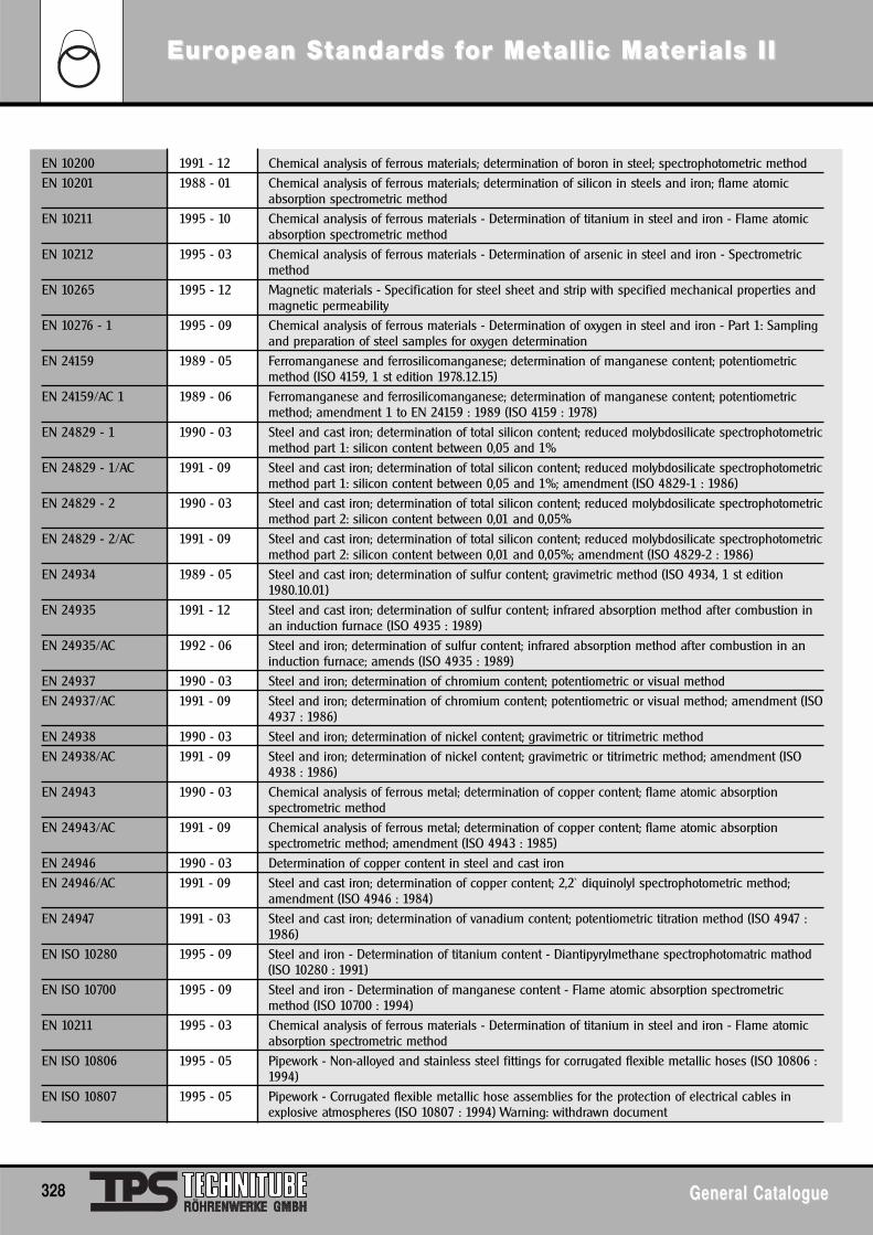
EN 10200 1991 - 12 Chemical analysis of ferrous materials; determination of boron in steel; spectrophotometric methodEN 10201 1988 - 01 Chemical analysis of ferrous materials; determination of silicon in steels and iron; flame atomic
absorption spectrometric methodEN 10211 1995 - 10 Chemical analysis of ferrous materials - Determination of titanium in steel and iron - Flame atomic
absorption spectrometric methodEN 10212 1995 - 03 Chemical analysis of ferrous materials - Determination of arsenic in steel and iron - Spectrometric
methodEN 10265 1995 - 12 Magnetic materials - Specification for steel sheet and strip with specified mechanical properties and
magnetic permeabilityEN 10276 - 1 1995 - 09 Chemical analysis of ferrous materials - Determination of oxygen in steel and iron - Part 1: Sampling
and preparation of steel samples for oxygen determinationEN 24159 1989 - 05 Ferromanganese and ferrosilicomanganese; determination of manganese content; potentiometric
method (ISO 4159, 1 st edition 1978.12.15)EN 24159/AC 1 1989 - 06 Ferromanganese and ferrosilicomanganese; determination of manganese content; potentiometric
method; amendment 1 to EN 24159 : 1989 (ISO 4159 : 1978)EN 24829 - 1 1990 - 03 Steel and cast iron; determination of total silicon content; reduced molybdosilicate spectrophotometric
method part 1: silicon content between 0,05 and 1%EN 24829 - 1/AC 1991 - 09 Steel and cast iron; determination of total silicon content; reduced molybdosilicate spectrophotometric
method part 1: silicon content between 0,05 and 1%; amendment (ISO 4829-1 : 1986)EN 24829 - 2 1990 - 03 Steel and cast iron; determination of total silicon content; reduced molybdosilicate spectrophotometric
method part 2: silicon content between 0,01 and 0,05%EN 24829 - 2/AC 1991 - 09 Steel and cast iron; determination of total silicon content; reduced molybdosilicate spectrophotometric
method part 2: silicon content between 0,01 and 0,05%; amendment (ISO 4829-2 : 1986)EN 24934 1989 - 05 Steel and cast iron; determination of sulfur content; gravimetric method (ISO 4934, 1 st edition
1980.10.01)EN 24935 1991 - 12 Steel and cast iron; determination of sulfur content; infrared absorption method after combustion in
an induction furnace (ISO 4935 : 1989)EN 24935/AC 1992 - 06 Steel and iron; determination of sulfur content; infrared absorption method after combustion in an
induction furnace; amends (ISO 4935 : 1989)EN 24937 1990 - 03 Steel and iron; determination of chromium content; potentiometric or visual methodEN 24937/AC 1991 - 09 Steel and iron; determination of chromium content; potentiometric or visual method; amendment (ISO
4937 : 1986)EN 24938 1990 - 03 Steel and iron; determination of nickel content; gravimetric or titrimetric methodEN 24938/AC 1991 - 09 Steel and iron; determination of nickel content; gravimetric or titrimetric method; amendment (ISO
4938 : 1986)EN 24943 1990 - 03 Chemical analysis of ferrous metal; determination of copper content; flame atomic absorption
spectrometric methodEN 24943/AC 1991 - 09 Chemical analysis of ferrous metal; determination of copper content; flame atomic absorption
spectrometric method; amendment (ISO 4943 : 1985)EN 24946 1990 - 03 Determination of copper content in steel and cast ironEN 24946/AC 1991 - 09 Steel and cast iron; determination of copper content; 2,2` diquinolyl spectrophotometric method;
amendment (ISO 4946 : 1984)EN 24947 1991 - 03 Steel and cast iron; determination of vanadium content; potentiometric titration method (ISO 4947 :
1986)EN ISO 10280 1995 - 09 Steel and iron - Determination of titanium content - Diantipyrylmethane spectrophotomatric mathod
(ISO 10280 : 1991)EN ISO 10700 1995 - 09 Steel and iron - Determination of manganese content - Flame atomic absorption spectrometric
method (ISO 10700 : 1994)EN 10211 1995 - 03 Chemical analysis of ferrous materials - Determination of titanium in steel and iron - Flame atomic
absorption spectrometric methodEN ISO 10806 1995 - 05 Pipework - Non-alloyed and stainless steel fittings for corrugated flexible metallic hoses (ISO 10806 :
1994)EN ISO 10807 1995 - 05 Pipework - Corrugated flexible metallic hose assemblies for the protection of electrical cables in
explosive atmospheres (ISO 10807 : 1994) Warning: withdrawn document
EurEuropean Sopean Sttandarandards fds for Meor Mettallic Matallic Matererials IIials II
328 General CatalogueGeneral Catalogue
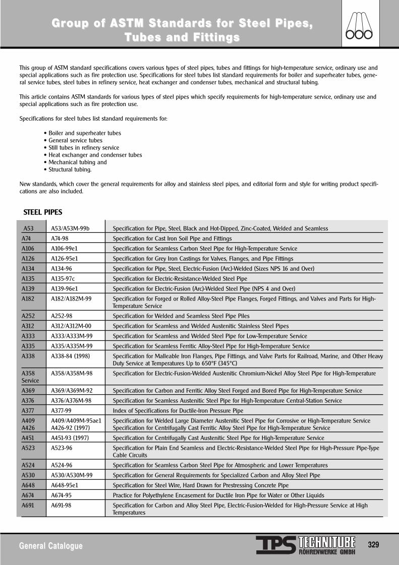
GrGroup of ASoup of ASTM STM Sttandarandards fds for Sor Stteel Pipes, eel Pipes, TTubes and Fubes and Fittingsittings
General CatalogueGeneral Catalogue 329
This group of ASTM standard specifications covers various types of steel pipes, tubes and fittings for high-temperature service, ordinary use andspecial applications such as fire protection use. Specifications for steel tubes list standard requirements for boiler and superheater tubes, gene-ral service tubes, steel tubes in refinery service, heat exchanger and condenser tubes, mechanical and structural tubing.
This article contains ASTM standards for various types of steel pipes which specify requirements for high-temperature service, ordinary use andspecial applications such as fire protection use.
Specifications for steel tubes list standard requirements for:
• Boiler and superheater tubes• General service tubes• Still tubes in refinery service• Heat exchanger and condenser tubes• Mechanical tubing and• Structural tubing.
New standards, which cover the general requirements for alloy and stainless steel pipes, and editorial form and style for writing product specifi-cations are also included.
STEEL PIPES
A53 A53/A53M-99b Specification for Pipe, Steel, Black and Hot-Dipped, Zinc-Coated, Welded and Seamless
A74 A74-98 Specification for Cast Iron Soil Pipe and Fittings
A106 A106-99e1 Specification for Seamless Carbon Steel Pipe for High-Temperature Service
A126 A126-95e1 Specification for Grey Iron Castings for Valves, Flanges, and Pipe Fittings
A134 A134-96 Specification for Pipe, Steel, Electric-Fusion (Arc)-Welded (Sizes NPS 16 and Over)
A135 A135-97c Specification for Electric-Resistance-Welded Steel Pipe
A139 A139-96e1 Specification for Electric-Fusion (Arc)-Welded Steel Pipe (NPS 4 and Over)
A182 A182/A182M-99 Specification for Forged or Rolled Alloy-Steel Pipe Flanges, Forged Fittings, and Valves and Parts for High-Temperature Service
A252 A252-98 Specification for Welded and Seamless Steel Pipe Piles
A312 A312/A312M-00 Specification for Seamless and Welded Austenitic Stainless Steel Pipes
A333 A333/A333M-99 Specification for Seamless and Welded Steel Pipe for Low-Temperature Service
A335 A335/A335M-99 Specification for Seamless Ferritic Alloy-Steel Pipe for High-Temperature Service
A338 A338-84 (1998) Specification for Malleable Iron Flanges, Pipe Fittings, and Valve Parts for Railroad, Marine, and Other HeavyDuty Service at Temperatures Up to 650°F (345°C)
A358 A358/A358M-98 Specification for Electric-Fusion-Welded Austenitic Chromium-Nickel Alloy Steel Pipe for High-TemperatureService
A369 A369/A369M-92 Specification for Carbon and Ferritic Alloy Steel Forged and Bored Pipe for High-Temperature Service
A376 A376/A376M-98 Specification for Seamless Austenitic Steel Pipe for High-Temperature Central-Station Service
A377 A377-99 Index of Specifications for Ductile-Iron Pressure Pipe
A409 A409/A409M-95ae1 Specification for Welded Large Diameter Austenitic Steel Pipe for Corrosive or High-Temperature ServiceA426 A426-92 (1997) Specification for Centrifugally Cast Ferritic Alloy Steel Pipe for High-Temperature Service
A451 A451-93 (1997) Specification for Centrifugally Cast Austenitic Steel Pipe for High-Temperature Service
A523 A523-96 Specification for Plain End Seamless and Electric-Resistance-Welded Steel Pipe for High-Pressure Pipe-TypeCable Circuits
A524 A524-96 Specification for Seamless Carbon Steel Pipe for Atmospheric and Lower Temperatures
A530 A530/A530M-99 Specification for General Requirements for Specialized Carbon and Alloy Steel Pipe
A648 A648-95e1 Specification for Steel Wire, Hard Drawn for Prestressing Concrete Pipe
A674 A674-95 Practice for Polyethylene Encasement for Ductile Iron Pipe for Water or Other Liquids
A691 A691-98 Specification for Carbon and Alloy Steel Pipe, Electric-Fusion-Welded for High-Pressure Service at HighTemperatures
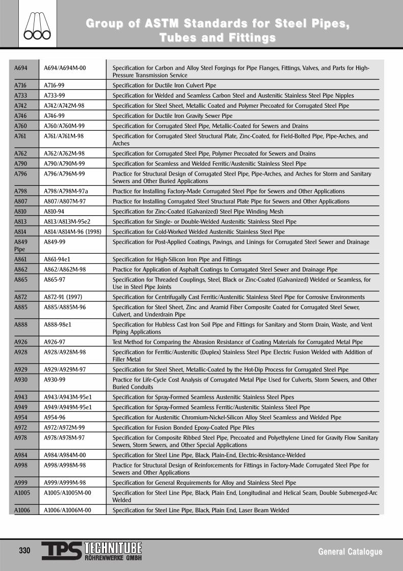
A694 A694/A694M-00 Specification for Carbon and Alloy Steel Forgings for Pipe Flanges, Fittings, Valves, and Parts for High-Pressure Transmission Service
A716 A716-99 Specification for Ductile Iron Culvert Pipe
A733 A733-99 Specification for Welded and Seamless Carbon Steel and Austenitic Stainless Steel Pipe Nipples
A742 A742/A742M-98 Specification for Steel Sheet, Metallic Coated and Polymer Precoated for Corrugated Steel Pipe
A746 A746-99 Specification for Ductile Iron Gravity Sewer Pipe
A760 A760/A760M-99 Specification for Corrugated Steel Pipe, Metallic-Coated for Sewers and Drains
A761 A761/A761M-98 Specification for Corrugated Steel Structural Plate, Zinc-Coated, for Field-Bolted Pipe, Pipe-Arches, andArches
A762 A762/A762M-98 Specification for Corrugated Steel Pipe, Polymer Precoated for Sewers and Drains
A790 A790/A790M-99 Specification for Seamless and Welded Ferritic/Austenitic Stainless Steel Pipe
A796 A796/A796M-99 Practice for Structural Design of Corrugated Steel Pipe, Pipe-Arches, and Arches for Storm and SanitarySewers and Other Buried Applications
A798 A798/A798M-97a Practice for Installing Factory-Made Corrugated Steel Pipe for Sewers and Other Applications
A807 A807/A807M-97 Practice for Installing Corrugated Steel Structural Plate Pipe for Sewers and Other Applications
A810 A810-94 Specification for Zinc-Coated (Galvanized) Steel Pipe Winding Mesh
A813 A813/A813M-95e2 Specification for Single- or Double-Welded Austenitic Stainless Steel Pipe
A814 A814/A814M-96 (1998) Specification for Cold-Worked Welded Austenitic Stainless Steel Pipe
A849 A849-99 Specification for Post-Applied Coatings, Pavings, and Linings for Corrugated Steel Sewer and DrainagePipe
A861 A861-94e1 Specification for High-Silicon Iron Pipe and Fittings
A862 A862/A862M-98 Practice for Application of Asphalt Coatings to Corrugated Steel Sewer and Drainage Pipe
A865 A865-97 Specification for Threaded Couplings, Steel, Black or Zinc-Coated (Galvanized) Welded or Seamless, forUse in Steel Pipe Joints
A872 A872-91 (1997) Specification for Centrifugally Cast Ferritic/Austenitic Stainless Steel Pipe for Corrosive Environments
A885 A885/A885M-96 Specification for Steel Sheet, Zinc and Aramid Fiber Composite Coated for Corrugated Steel Sewer,Culvert, and Underdrain Pipe
A888 A888-98e1 Specification for Hubless Cast Iron Soil Pipe and Fittings for Sanitary and Storm Drain, Waste, and VentPiping Applications
A926 A926-97 Test Method for Comparing the Abrasion Resistance of Coating Materials for Corrugated Metal Pipe
A928 A928/A928M-98 Specification for Ferritic/Austenitic (Duplex) Stainless Steel Pipe Electric Fusion Welded with Addition ofFiller Metal
A929 A929/A929M-97 Specification for Steel Sheet, Metallic-Coated by the Hot-Dip Process for Corrugated Steel Pipe
A930 A930-99 Practice for Life-Cycle Cost Analysis of Corrugated Metal Pipe Used for Culverts, Storm Sewers, and OtherBuried Conduits
A943 A943/A943M-95e1 Specification for Spray-Formed Seamless Austenitic Stainless Steel Pipes
A949 A949/A949M-95e1 Specification for Spray-Formed Seamless Ferritic/Austenitic Stainless Steel Pipe
A954 A954-96 Specification for Austenitic Chromium-Nickel-Silicon Alloy Steel Seamless and Welded Pipe
A972 A972/A972M-99 Specification for Fusion Bonded Epoxy-Coated Pipe Piles
A978 A978/A978M-97 Specification for Composite Ribbed Steel Pipe, Precoated and Polyethylene Lined for Gravity Flow SanitarySewers, Storm Sewers, and Other Special Applications
A984 A984/A984M-00 Specification for Steel Line Pipe, Black, Plain-End, Electric-Resistance-Welded
A998 A998/A998M-98 Practice for Structural Design of Reinforcements for Fittings in Factory-Made Corrugated Steel Pipe forSewers and Other Applications
A999 A999/A999M-98 Specification for General Requirements for Alloy and Stainless Steel Pipe
A1005 A1005/A1005M-00 Specification for Steel Line Pipe, Black, Plain End, Longitudinal and Helical Seam, Double Submerged-ArcWelded
A1006 A1006/A1006M-00 Specification for Steel Line Pipe, Black, Plain End, Laser Beam Welded
GrGroup of ASoup of ASTM STM Sttandarandards fds for Sor Stteel Pipes, eel Pipes, TTubes and Fubes and Fittingsittings
330 General CatalogueGeneral Catalogue
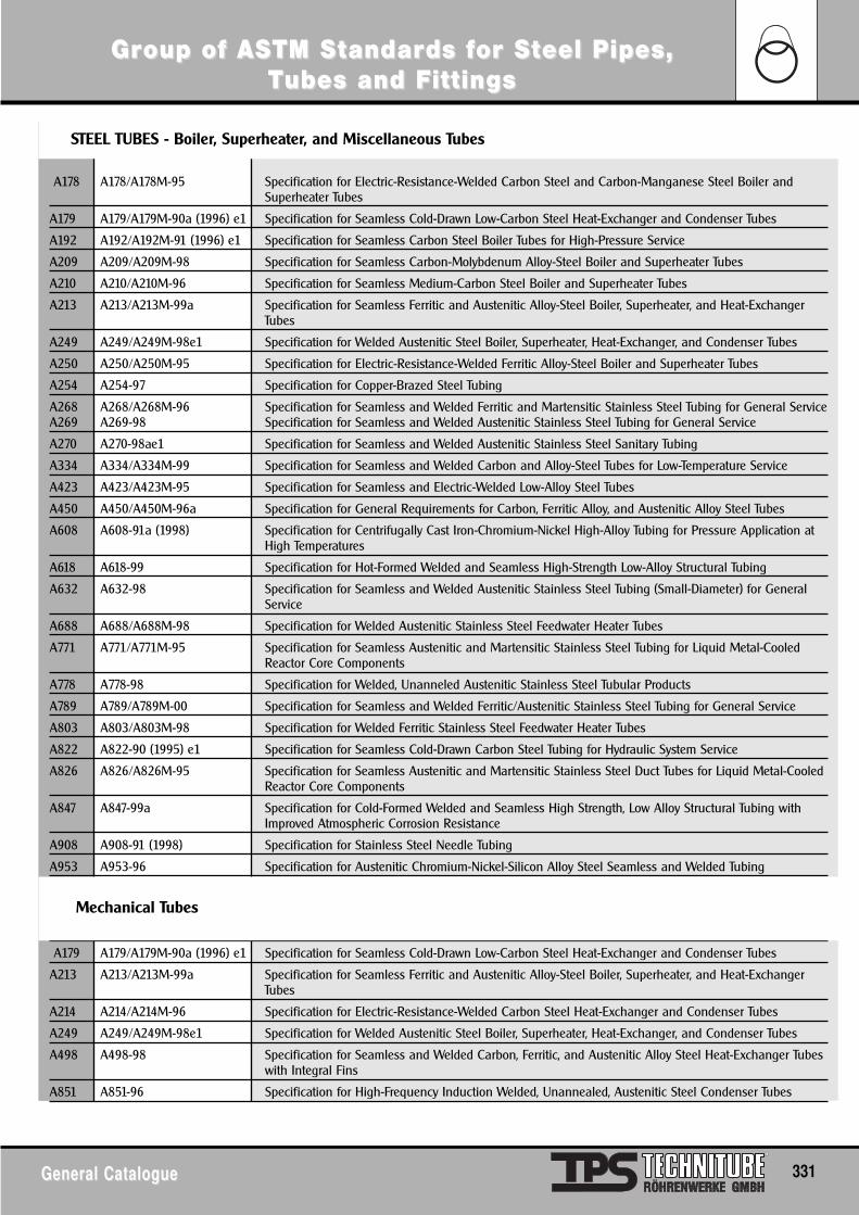
GrGroup of ASoup of ASTM STM Sttandarandards fds for Sor Stteel Pipes, eel Pipes, TTubes and Fubes and Fittingsittings
General CatalogueGeneral Catalogue 331
A178 A178/A178M-95 Specification for Electric-Resistance-Welded Carbon Steel and Carbon-Manganese Steel Boiler andSuperheater Tubes
A179 A179/A179M-90a (1996) e1 Specification for Seamless Cold-Drawn Low-Carbon Steel Heat-Exchanger and Condenser Tubes
A192 A192/A192M-91 (1996) e1 Specification for Seamless Carbon Steel Boiler Tubes for High-Pressure Service
A209 A209/A209M-98 Specification for Seamless Carbon-Molybdenum Alloy-Steel Boiler and Superheater Tubes
A210 A210/A210M-96 Specification for Seamless Medium-Carbon Steel Boiler and Superheater Tubes
A213 A213/A213M-99a Specification for Seamless Ferritic and Austenitic Alloy-Steel Boiler, Superheater, and Heat-ExchangerTubes
A249 A249/A249M-98e1 Specification for Welded Austenitic Steel Boiler, Superheater, Heat-Exchanger, and Condenser Tubes
A250 A250/A250M-95 Specification for Electric-Resistance-Welded Ferritic Alloy-Steel Boiler and Superheater Tubes
A254 A254-97 Specification for Copper-Brazed Steel Tubing
A268 A268/A268M-96 Specification for Seamless and Welded Ferritic and Martensitic Stainless Steel Tubing for General ServiceA269 A269-98 Specification for Seamless and Welded Austenitic Stainless Steel Tubing for General Service
A270 A270-98ae1 Specification for Seamless and Welded Austenitic Stainless Steel Sanitary Tubing
A334 A334/A334M-99 Specification for Seamless and Welded Carbon and Alloy-Steel Tubes for Low-Temperature Service
A423 A423/A423M-95 Specification for Seamless and Electric-Welded Low-Alloy Steel Tubes
A450 A450/A450M-96a Specification for General Requirements for Carbon, Ferritic Alloy, and Austenitic Alloy Steel Tubes
A608 A608-91a (1998) Specification for Centrifugally Cast Iron-Chromium-Nickel High-Alloy Tubing for Pressure Application atHigh Temperatures
A618 A618-99 Specification for Hot-Formed Welded and Seamless High-Strength Low-Alloy Structural Tubing
A632 A632-98 Specification for Seamless and Welded Austenitic Stainless Steel Tubing (Small-Diameter) for GeneralService
A688 A688/A688M-98 Specification for Welded Austenitic Stainless Steel Feedwater Heater Tubes
A771 A771/A771M-95 Specification for Seamless Austenitic and Martensitic Stainless Steel Tubing for Liquid Metal-CooledReactor Core Components
A778 A778-98 Specification for Welded, Unanneled Austenitic Stainless Steel Tubular Products
A789 A789/A789M-00 Specification for Seamless and Welded Ferritic/Austenitic Stainless Steel Tubing for General Service
A803 A803/A803M-98 Specification for Welded Ferritic Stainless Steel Feedwater Heater Tubes
A822 A822-90 (1995) e1 Specification for Seamless Cold-Drawn Carbon Steel Tubing for Hydraulic System Service
A826 A826/A826M-95 Specification for Seamless Austenitic and Martensitic Stainless Steel Duct Tubes for Liquid Metal-CooledReactor Core Components
A847 A847-99a Specification for Cold-Formed Welded and Seamless High Strength, Low Alloy Structural Tubing withImproved Atmospheric Corrosion Resistance
A908 A908-91 (1998) Specification for Stainless Steel Needle Tubing
A953 A953-96 Specification for Austenitic Chromium-Nickel-Silicon Alloy Steel Seamless and Welded Tubing
A179 A179/A179M-90a (1996) e1 Specification for Seamless Cold-Drawn Low-Carbon Steel Heat-Exchanger and Condenser Tubes
A213 A213/A213M-99a Specification for Seamless Ferritic and Austenitic Alloy-Steel Boiler, Superheater, and Heat-ExchangerTubes
A214 A214/A214M-96 Specification for Electric-Resistance-Welded Carbon Steel Heat-Exchanger and Condenser Tubes
A249 A249/A249M-98e1 Specification for Welded Austenitic Steel Boiler, Superheater, Heat-Exchanger, and Condenser Tubes
A498 A498-98 Specification for Seamless and Welded Carbon, Ferritic, and Austenitic Alloy Steel Heat-Exchanger Tubeswith Integral Fins
A851 A851-96 Specification for High-Frequency Induction Welded, Unannealed, Austenitic Steel Condenser Tubes
Mechanical Tubes
STEEL TUBES - Boiler, Superheater, and Miscellaneous Tubes
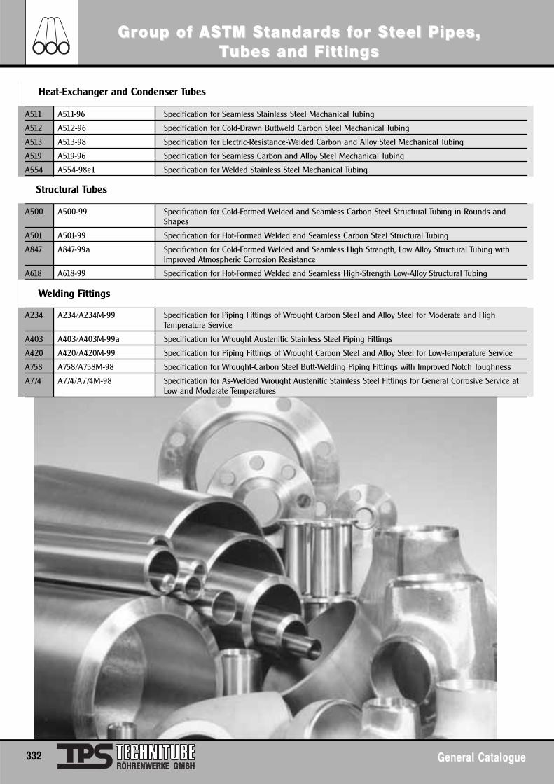
A511 A511-96 Specification for Seamless Stainless Steel Mechanical Tubing
A512 A512-96 Specification for Cold-Drawn Buttweld Carbon Steel Mechanical Tubing
A513 A513-98 Specification for Electric-Resistance-Welded Carbon and Alloy Steel Mechanical Tubing
A519 A519-96 Specification for Seamless Carbon and Alloy Steel Mechanical Tubing
A554 A554-98e1 Specification for Welded Stainless Steel Mechanical Tubing
A500 A500-99 Specification for Cold-Formed Welded and Seamless Carbon Steel Structural Tubing in Rounds andShapes
A501 A501-99 Specification for Hot-Formed Welded and Seamless Carbon Steel Structural Tubing
A847 A847-99a Specification for Cold-Formed Welded and Seamless High Strength, Low Alloy Structural Tubing withImproved Atmospheric Corrosion Resistance
A618 A618-99 Specification for Hot-Formed Welded and Seamless High-Strength Low-Alloy Structural Tubing
A234 A234/A234M-99 Specification for Piping Fittings of Wrought Carbon Steel and Alloy Steel for Moderate and HighTemperature Service
A403 A403/A403M-99a Specification for Wrought Austenitic Stainless Steel Piping Fittings
A420 A420/A420M-99 Specification for Piping Fittings of Wrought Carbon Steel and Alloy Steel for Low-Temperature Service
A758 A758/A758M-98 Specification for Wrought-Carbon Steel Butt-Welding Piping Fittings with Improved Notch Toughness
A774 A774/A774M-98 Specification for As-Welded Wrought Austenitic Stainless Steel Fittings for General Corrosive Service atLow and Moderate Temperatures
Heat-Exchanger and Condenser Tubes
Structural Tubes
Welding Fittings
GrGroup of ASoup of ASTM STM Sttandarandards fds for Sor Stteel Pipes, eel Pipes, TTubes and Fubes and Fittingsittings
332 General CatalogueGeneral Catalogue
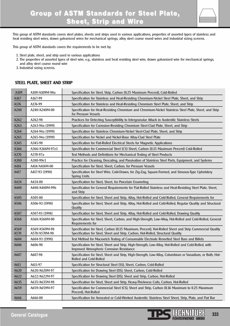
GrGroup of ASoup of ASTM STM Sttandarandards fds for Sor Stteel Plateel Plate, e, SheeSheet, St, Strtrip and Wip and Wiriree
General CatalogueGeneral Catalogue 333
A109 A109/A109M-98a Specification for Steel, Strip, Carbon (0.25 Maximum Percent), Cold-Rolled
A167 A167-99 Specification for Stainless and Heat-Resisting Chromium-Nickel Steel Plate, Sheet, and Strip
A176 A176-99 Specification for Stainless and Heat-Resisting Chromium Steel Plate, Sheet, and Strip
A240 A240/A240M-00 Specification for Heat-Resisting Chromium and Chromium-Nickel Stainless Steel Plate, Sheet, and Stripfor Pressure Vessels
A262 A262-98 Practices for Detecting Susceptibility to Intergranular Attack in Austenitic Stainless Steels
A263 A263-94a (1999) Specification for Corrosion-Resisting Chromium Steel-Clad Plate, Sheet, and Strip
A264 A264-94a (1999) Specification for Stainless Chromium-Nickel Steel-Clad Plate, Sheet, and Strip
A265 A265-94a (1999) Specification for Nickel and Nickel-Base Alloy-Clad Steel Plate
A345 A345-98 Specification for Flat-Rolled Electrical Steels for Magnetic Applications
A366 A366/A366M-97e1 Specification for Commercial Steel (CS) Sheet, Carbon (0.15 Maximum Percent) Cold-Rolled
A370 A370-97a Test Methods and Definitions for Mechanical Testing of Steel Products
A380 A380-99e1 Practice for Cleaning, Descaling, and Passivation of Stainless Steel Parts, Equipment, and Systems
A414 A414/A414M-00 Specification for Steel, Sheet, Carbon, for Pressure Vessels
A417 A417-93 (1998) Specification for Steel Wire, Cold-Drawn, for Zig-Zag, Square-Formed, and Sinuous-Type UpholsterySpring Units
A424 A424-00 Specification for Steel, Sheet, for Porcelain Enameling
A480 A480/A480M-99b Specification for General Requirements for Flat-Rolled Stainless and Heat-Resisting Steel Plate, Sheet,and Strip
A505 A505-00 Specification for Steel, Sheet and Strip, Alloy, Hot-Rolled and Cold-Rolled, General Requirements for
A506 A506-93 (1998) Specification for Steel, Sheet and Strip, Alloy, Hot-Rolled and Cold-Rolled, Regular Quality and StructuralQuality
A507 A507-93 (1998) Specification for Steel, Sheet and Strip, Alloy, Hot-Rolled and Cold-Rolled, Drawing Quality
A568 A568/A568M-00 Specification for Steel, Sheet, Carbon, and High-Strength, Low-Alloy, Hot-Rolled and Cold-Rolled, GeneralRequirements for
A569 A569/A569M-98 Specification for Steel, Carbon (0.15 Maximum, Percent), Hot-Rolled Sheet and Strip Commercial QualityA570 A570/A570M-98 Specification for Steel, Sheet and Strip, Carbon, Hot-Rolled, Structural Quality
A604 A604-93 (1998) Test Method for Macroetch Testing of Consumable Electrode Remelted Steel Bars and Billets
A606 A606-98 Specification for Steel, Sheet and Strip, High-Strength, Low-Alloy, Hot-Rolled and Cold-Rolled, withImproved Atmospheric Corrosion Resistance
A607 A607-98 Specification for Steel, Sheet and Strip, High-Strength, Low-Alloy, Columbium or Vanadium, or Both, Hot-Rolled and Cold-Rolled
A611 A611-97 Specification for Structural Steel (SS), Sheet, Carbon, Cold-Rolled
A620 A620/A620M-97 Specification for Drawing Steel (DS), Sheet, Carbon, Cold-Rolled
A622 A622/A622M-97 Specification for Drawing Steel (DS), Sheet and Strip, Carbon, Hot-Rolled
A635 A635/A635M-98 Specification for Steel, Sheet and Strip, Heavy-Thickness Coils, Carbon, Hot-Rolled
A659 A659/A659M-97 Specification for Commercial Steel (CS), Sheet and Strip, Carbon (0.16 Maximum to 0.25 MaximumPercent), Hot-Rolled
A666 A666-00 Specification for Annealed or Cold-Worked Austenitic Stainless Steel Sheet, Strip, Plate, and Flat Bar
This group of ASTM standards covers steel plates, sheets and strips used in various applications, properties of assorted types of stainless andheat resisting steel wires, drawn galvanized wires for mechanical springs, alloy steel coarse round wires and industrial sizing screens.
This group of ASTM standards covers the requirements to be met by:
1. Steel plate, sheet, and strip used in various applications2. The properties of assorted types of steel wire, e.g., stainless and heat resisting steel wire, drawn galvanized wire for mechanical springs,
and alloy steel coarse round wire3. Industrial sizing screens.
STEEL PLATE, SHEET AND STRIP
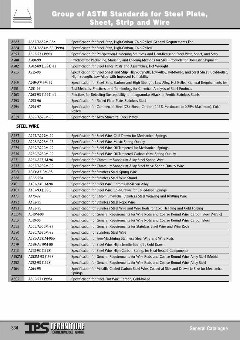
A682 A682/A682M-98a Specification for Steel, Strip, High-Carbon, Cold-Rolled, General Requirements For
A684 A684/A684M-86 (1998) Specification for Steel, Strip, High-Carbon, Cold-Rolled
A693 A693-93 (1999) Specification for Precipitation-Hardening Stainless and Heat-Resisting Steel Plate, Sheet, and Strip
A700 A700-99 Practices for Packaging, Marking, and Loading Methods for Steel Products for Domestic Shipment
A702 A702-89 (1994) e1 Specification for Steel Fence Posts and Assemblies, Hot Wrought
A715 A715-98 Specification for Steel Sheet and Strip, High-Strength, Low-Alloy, Hot-Rolled, and Steel Sheet, Cold-Rolled,High-Strength, Low-Alloy, with Improved Formability
A749 A749/A749M-97 Specification for Steel, Strip, Carbon and High-Strength, Low-Alloy, Hot-Rolled, General Requirements for
A751 A751-96 Test Methods, Practices, and Terminology for Chemical Analysis of Steel Products
A763 A763-93 (1999) e1 Practices for Detecting Susceptibility to Intergranular Attack in Ferritic Stainless Steels
A793 A793-96 Specification for Rolled Floor Plate, Stainless Steel
A794 A794-97 Specification for Commercial Steel (CS), Sheet, Carbon (0.16% Maximum to 0.25% Maximum), Cold-Rolled
A829 A829/A829M-95 Specification for Alloy Structural Steel Plates
A227 A227/A227M-99 Specification for Steel Wire, Cold-Drawn for Mechanical Springs
A228 A228/A228M-93 Specification for Steel Wire, Music Spring Quality
A229 A229/A229M-99 Specification for Steel Wire, Oil-Tempered for Mechanical Springs
A230 A230/A230M-99 Specification for Steel Wire, Oil-Tempered Carbon Valve Spring Quality
A231 A231/A231M-96 Specification for Chromium-Vanadium Alloy Steel Spring Wire
A232 A232/A232M-99 Specification for Chromium-Vanadium Alloy Steel Valve Spring Quality Wire
A313 A313/A313M-98 Specification for Stainless Steel Spring Wire
A368 A368-95a Specification for Stainless Steel Wire Strand
A401 A401/A401M-98 Specification for Steel Wire, Chromium-Silicon Alloy
A407 A407-93 (1998) Specification for Steel Wire, Cold-Drawn, for Coiled-Type Springs
A478 A478-97 Specification for Chromium-Nickel Stainless Steel Weaving and Knitting Wire
A492 A492-95 Specification for Stainless Steel Rope Wire
A493 A493-95 Specification for Stainless Steel Wire and Wire Rods for Cold Heading and Cold Forging
A510M A510M-00 Specification for General Requirements for Wire Rods and Coarse Round Wire, Carbon Steel [Metric]
A510 A510-00 Specification for General Requirements for Wire Rods and Coarse Round Wire, Carbon Steel
A555 A555/A555M-97 Specification for General Requirements for Stainless Steel Wire and Wire Rods
A580 A580/A580M-98 Specification for Stainless Steel Wire
A581 A581/A581M-95b Specification for Free-Machining Stainless Steel Wire and Wire Rods
A679 A679/A679M-00 Specification for Steel Wire, High Tensile Strength, Cold Drawn
A713 A713-93 (1998) Specification for Steel Wire, High-Carbon Spring, for Heat-Treated Components
A752M A752M-93 (1998) Specification for General Requirements for Wire Rods and Coarse Round Wire, Alloy Steel [Metric]
A752 A752-93 (1998) Specification for General Requirements for Wire Rods and Coarse Round Wire, Alloy Steel
A764 A764-95 Specification for Metallic Coated Carbon Steel Wire, Coated at Size and Drawn to Size for MechanicalSprings
A805 A805-93 (1998) Specification for Steel, Flat Wire, Carbon, Cold-Rolled
STEEL WIRE
GrGroup of ASoup of ASTM STM Sttandarandards fds for Sor Stteel Plateel Plate, e, SheeSheet, St, Strtrip and Wip and Wiriree
334 General CatalogueGeneral Catalogue
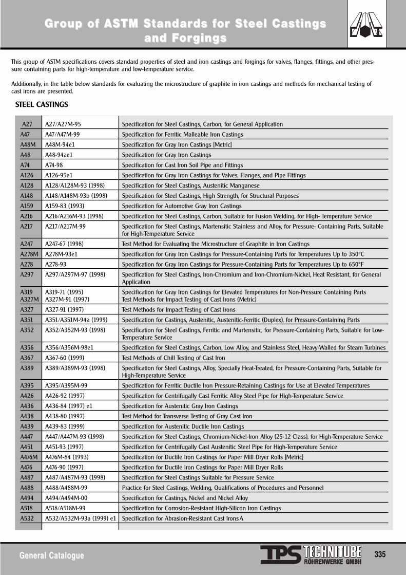
This group of ASTM specifications covers standard properties of steel and iron castings and forgings for valves, flanges, fittings, and other pres-sure containing parts for high-temperature and low-temperature service.
Additionally, in the table below standards for evaluating the microstructure of graphite in iron castings and methods for mechanical testing ofcast irons are presented.
STEEL CASTINGS
A27 A27/A27M-95 Specification for Steel Castings, Carbon, for General Application
A47 A47/A47M-99 Specification for Ferritic Malleable Iron Castings
A48M A48M-94e1 Specification for Gray Iron Castings [Metric]
A48 A48-94ae1 Specification for Gray Iron Castings
A74 A74-98 Specification for Cast Iron Soil Pipe and Fittings
A126 A126-95e1 Specification for Gray Iron Castings for Valves, Flanges, and Pipe Fittings
A128 A128/A128M-93 (1998) Specification for Steel Castings, Austenitic Manganese
A148 A148/A148M-93b (1998) Specification for Steel Castings, High Strength, for Structural Purposes
A159 A159-83 (1993) Specification for Automotive Gray Iron Castings
A216 A216/A216M-93 (1998) Specification for Steel Castings, Carbon, Suitable for Fusion Welding, for High- Temperature Service
A217 A217/A217M-99 Specification for Steel Castings, Martensitic Stainless and Alloy, for Pressure- Containing Parts, Suitablefor High-Temperature Service
A247 A247-67 (1998) Test Method for Evaluating the Microstructure of Graphite in Iron Castings
A278M A278M-93e1 Specification for Gray Iron Castings for Pressure-Containing Parts for Temperatures Up to 350°C
A278 A278-93 Specification for Gray Iron Castings for Pressure-Containing Parts for Temperatures Up to 650°F
A297 A297/A297M-97 (1998) Specification for Steel Castings, Iron-Chromium and Iron-Chromium-Nickel, Heat Resistant, for GeneralApplication
A319 A319-71 (1995) Specification for Gray Iron Castings for Elevated Temperatures for Non-Pressure Containing PartsA327M A327M-91 (1997) Test Methods for Impact Testing of Cast Irons (Metric)
A327 A327-91 (1997) Test Methods for Impact Testing of Cast Irons
A351 A351/A351M-94a (1999) Specification for Castings, Austenitic, Austenitic-Ferritic (Duplex), for Pressure-Containing Parts
A352 A352/A352M-93 (1998) Specification for Steel Castings, Ferritic and Martensitic, for Pressure-Containing Parts, Suitable for Low-Temperature Service
A356 A356/A356M-98e1 Specification for Steel Castings, Carbon, Low Alloy, and Stainless Steel, Heavy-Walled for Steam Turbines
A367 A367-60 (1999) Test Methods of Chill Testing of Cast Iron
A389 A389/A389M-93 (1998) Specification for Steel Castings, Alloy, Specially Heat-Treated, for Pressure-Containing Parts, Suitable forHigh-Temperature Service
A395 A395/A395M-99 Specification for Ferritic Ductile Iron Pressure-Retaining Castings for Use at Elevated Temperatures
A426 A426-92 (1997) Specification for Centrifugally Cast Ferritic Alloy Steel Pipe for High-Temperature Service
A436 A436-84 (1997) e1 Specification for Austenitic Gray Iron Castings
A438 A438-80 (1997) Test Method for Transverse Testing of Gray Cast Iron
A439 A439-83 (1999) Specification for Austenitic Ductile Iron Castings
A447 A447/A447M-93 (1998) Specification for Steel Castings, Chromium-Nickel-Iron Alloy (25-12 Class), for High-Temperature Service
A451 A451-93 (1997) Specification for Centrifugally Cast Austenitic Steel Pipe for High-Temperature Service
A476M A476M-84 (1993) Specification for Ductile Iron Castings for Paper Mill Dryer Rolls [Metric]
A476 A476-90 (1997) Specification for Ductile Iron Castings for Paper Mill Dryer Rolls
A487 A487/A487M-93 (1998) Specification for Steel Castings Suitable for Pressure Service
A488 A488/A488M-99 Practice for Steel Castings, Welding, Qualifications of Procedures and Personnel
A494 A494/A494M-00 Specification for Castings, Nickel and Nickel Alloy
A518 A518/A518M-99 Specification for Corrosion-Resistant High-Silicon Iron Castings
A532 A532/A532M-93a (1999) e1 Specification for Abrasion-Resistant Cast IronsA
GrGroup of ASoup of ASTM STM Sttandarandards fds for Sor Stteel Caseel Castings tings and Fand Fororgingsgings
General CatalogueGeneral Catalogue 335
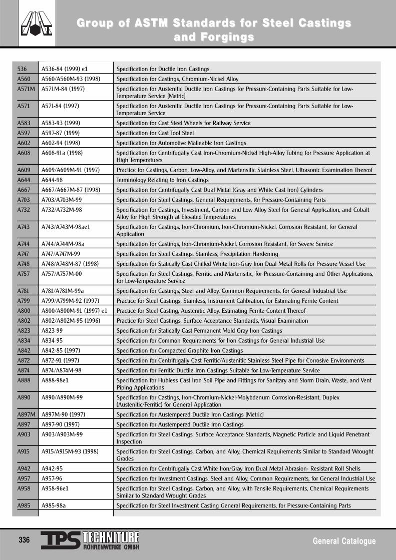
536 A536-84 (1999) e1 Specification for Ductile Iron Castings
A560 A560/A560M-93 (1998) Specification for Castings, Chromium-Nickel Alloy
A571M A571M-84 (1997) Specification for Austenitic Ductile Iron Castings for Pressure-Containing Parts Suitable for Low-Temperature Service [Metric]
A571 A571-84 (1997) Specification for Austenitic Ductile Iron Castings for Pressure-Containing Parts Suitable for Low-Temperature Service
A583 A583-93 (1999) Specification for Cast Steel Wheels for Railway Service
A597 A597-87 (1999) Specification for Cast Tool Steel
A602 A602-94 (1998) Specification for Automotive Malleable Iron Castings
A608 A608-91a (1998) Specification for Centrifugally Cast Iron-Chromium-Nickel High-Alloy Tubing for Pressure Application atHigh Temperatures
A609 A609/A609M-91 (1997) Practice for Castings, Carbon, Low-Alloy, and Martensitic Stainless Steel, Ultrasonic Examination Thereof
A644 A644-98 Terminology Relating to Iron Castings
A667 A667/A667M-87 (1998) Specification for Centrifugally Cast Dual Metal (Gray and White Cast Iron) Cylinders
A703 A703/A703M-99 Specification for Steel Castings, General Requirements, for Pressure-Containing Parts
A732 A732/A732M-98 Specification for Castings, Investment, Carbon and Low Alloy Steel for General Application, and CobaltAlloy for High Strength at Elevated Temperatures
A743 A743/A743M-98ae1 Specification for Castings, Iron-Chromium, Iron-Chromium-Nickel, Corrosion Resistant, for GeneralApplication
A744 A744/A744M-98a Specification for Castings, Iron-Chromium-Nickel, Corrosion Resistant, for Severe Service
A747 A747/A747M-99 Specification for Steel Castings, Stainless, Precipitation Hardening
A748 A748/A748M-87 (1998) Specification for Statically Cast Chilled White Iron-Gray Iron Dual Metal Rolls for Pressure Vessel Use
A757 A757/A757M-00 Specification for Steel Castings, Ferritic and Martensitic, for Pressure-Containing and Other Applications,for Low-Temperature Service
A781 A781/A781M-99a Specification for Castings, Steel and Alloy, Common Requirements, for General Industrial Use
A799 A799/A799M-92 (1997) Practice for Steel Castings, Stainless, Instrument Calibration, for Estimating Ferrite Content
A800 A800/A800M-91 (1997) e1 Practice for Steel Casting, Austenitic Alloy, Estimating Ferrite Content Thereof
A802 A802/A802M-95 (1996) Practice for Steel Castings, Surface Acceptance Standards, Visual Examination
A823 A823-99 Specification for Statically Cast Permanent Mold Gray Iron Castings
A834 A834-95 Specification for Common Requirements for Iron Castings for General Industrial Use
A842 A842-85 (1997) Specification for Compacted Graphite Iron Castings
A872 A872-91 (1997) Specification for Centrifugally Cast Ferritic/Austenitic Stainless Steel Pipe for Corrosive Environments
A874 A874/A874M-98 Specification for Ferritic Ductile Iron Castings Suitable for Low-Temperature Service
A888 A888-98e1 Specification for Hubless Cast Iron Soil Pipe and Fittings for Sanitary and Storm Drain, Waste, and VentPiping Applications
A890 A890/A890M-99 Specification for Castings, Iron-Chromium-Nickel-Molybdenum Corrosion-Resistant, Duplex(Austenitic/Ferritic) for General Application
A897M A897M-90 (1997) Specification for Austempered Ductile Iron Castings [Metric]
A897 A897-90 (1997) Specification for Austempered Ductile Iron Castings
A903 A903/A903M-99 Specification for Steel Castings, Surface Acceptance Standards, Magnetic Particle and Liquid PenetrantInspection
A915 A915/A915M-93 (1998) Specification for Steel Castings, Carbon, and Alloy, Chemical Requirements Similar to Standard WroughtGrades
A942 A942-95 Specification for Centrifugally Cast White Iron/Gray Iron Dual Metal Abrasion- Resistant Roll Shells
A957 A957-96 Specification for Investment Castings, Steel and Alloy, Common Requirements, for General Industrial Use
A958 A958-96e1 Specification for Steel Castings, Carbon, and Alloy, with Tensile Requirements, Chemical RequirementsSimilar to Standard Wrought Grades
A985 A985-98a Specification for Steel Investment Casting General Requirements, for Pressure-Containing Parts
GrGroup of ASoup of ASTM STM Sttandarandards fds for Sor Stteel Caseel Castings tings and Fand Fororgingsgings
336 General CatalogueGeneral Catalogue
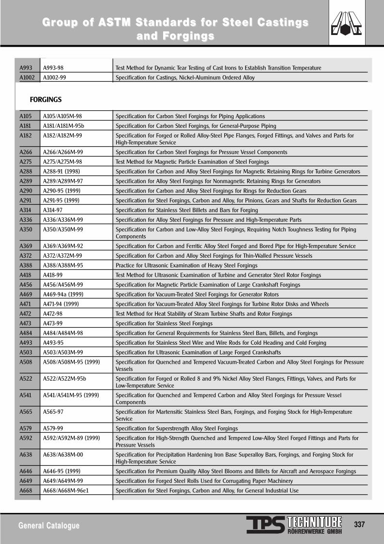
GrGroup of ASoup of ASTM STM Sttandarandards fds for Sor Stteel Caseel Castings tings and Fand Fororgingsgings
General CatalogueGeneral Catalogue 337
A993 A993-98 Test Method for Dynamic Tear Testing of Cast Irons to Establish Transition Temperature
A1002 A1002-99 Specification for Castings, Nickel-Aluminum Ordered Alloy
A105 A105/A105M-98 Specification for Carbon Steel Forgings for Piping Applications
A181 A181/A181M-95b Specification for Carbon Steel Forgings, for General-Purpose Piping
A182 A182/A182M-99 Specification for Forged or Rolled Alloy-Steel Pipe Flanges, Forged Fittings, and Valves and Parts forHigh-Temperature Service
A266 A266/A266M-99 Specification for Carbon Steel Forgings for Pressure Vessel Components
A275 A275/A275M-98 Test Method for Magnetic Particle Examination of Steel Forgings
A288 A288-91 (1998) Specification for Carbon and Alloy Steel Forgings for Magnetic Retaining Rings for Turbine Generators
A289 A289/A289M-97 Specification for Alloy Steel Forgings for Nonmagnetic Retaining Rings for Generators
A290 A290-95 (1999) Specification for Carbon and Alloy Steel Forgings for Rings for Reduction Gears
A291 A291-95 (1999) Specification for Steel Forgings, Carbon and Alloy, for Pinions, Gears and Shafts for Reduction Gears
A314 A314-97 Specification for Stainless Steel Billets and Bars for Forging
A336 A336/A336M-99 Specification for Alloy Steel Forgings for Pressure and High-Temperature Parts
A350 A350/A350M-99 Specification for Carbon and Low-Alloy Steel Forgings, Requiring Notch Toughness Testing for PipingComponents
A369 A369/A369M-92 Specification for Carbon and Ferritic Alloy Steel Forged and Bored Pipe for High-Temperature Service
A372 A372/A372M-99 Specification for Carbon and Alloy Steel Forgings for Thin-Walled Pressure Vessels
A388 A388/A388M-95 Practice for Ultrasonic Examination of Heavy Steel Forgings
A418 A418-99 Test Method for Ultrasonic Examination of Turbine and Generator Steel Rotor Forgings
A456 A456/A456M-99 Specification for Magnetic Particle Examination of Large Crankshaft Forgings
A469 A469-94a (1999) Specification for Vacuum-Treated Steel Forgings for Generator Rotors
A471 A471-94 (1999) Specification for Vacuum-Treated Alloy Steel Forgings for Turbine Rotor Disks and Wheels
A472 A472-98 Test Method for Heat Stability of Steam Turbine Shafts and Rotor Forgings
A473 A473-99 Specification for Stainless Steel Forgings
A484 A484/A484M-98 Specification for General Requirements for Stainless Steel Bars, Billets, and Forgings
A493 A493-95 Specification for Stainless Steel Wire and Wire Rods for Cold Heading and Cold Forging
A503 A503/A503M-99 Specification for Ultrasonic Examination of Large Forged Crankshafts
A508 A508/A508M-95 (1999) Specification for Quenched and Tempered Vacuum-Treated Carbon and Alloy Steel Forgings for PressureVessels
A522 A522/A522M-95b Specification for Forged or Rolled 8 and 9% Nickel Alloy Steel Flanges, Fittings, Valves, and Parts forLow-Temperature Service
A541 A541/A541M-95 (1999) Specification for Quenched and Tempered Carbon and Alloy Steel Forgings for Pressure VesselComponents
A565 A565-97 Specification for Martensitic Stainless Steel Bars, Forgings, and Forging Stock for High-TemperatureService
A579 A579-99 Specification for Superstrength Alloy Steel Forgings
A592 A592/A592M-89 (1999) Specification for High-Strength Quenched and Tempered Low-Alloy Steel Forged Fittings and Parts forPressure Vessels
A638 A638/A638M-00 Specification for Precipitation Hardening Iron Base Superalloy Bars, Forgings, and Forging Stock forHigh-Temperature Service
A646 A646-95 (1999) Specification for Premium Quality Alloy Steel Blooms and Billets for Aircraft and Aerospace Forgings
A649 A649/A649M-99 Specification for Forged Steel Rolls Used for Corrugating Paper Machinery
A668 A668/A668M-96e1 Specification for Steel Forgings, Carbon and Alloy, for General Industrial Use
FORGINGS
A694 A694/A694M-00 Specification for Carbon and Alloy Steel Forgings for Pipe Flanges, Fittings, Valves, and Parts for High-Pressure Transmission Service
A705 A705/A705M-95 Specification for Age-Hardening Stainless Steel Forgings
A707 A707/A707M-00 Specification for Forged Carbon and Alloy Steel Flanges for Low-Temperature Service
A711 A711-92 (1996) e1 Specification for Steel Forging Stock
A723 A723/A723M-94 (1999) Specification for Alloy Steel Forgings for High-Strength Pressure Component Application
A727 A727/A727M-97 Specification for Carbon Steel Forgings for Piping Components with Inherent Notch Toughness
A730 A730-93 (1999) Specification for Forgings, Carbon and Alloy Steel, for Railway Use
A745 A745/A745M-94 (1999) Practice for Ultrasonic Examination of Austenitic Steel Forgings
A765 A765/A765M-98a Specification for Carbon Steel and Low-Alloy Steel Pressure-Vessel-Component Forgings with MandatoryToughness Requirements
A768 A768-95 Specification for Vacuum-Treated 12% Chromium Alloy Steel Forgings for Turbine Rotors and Shafts
A788 A788-98a Specification for Steel Forgings, General Requirements
A831 A831/A831M-95 Specification for Austenitic and Martensitic Stainless Steel Bars, Billets, and Forgings for Liquid MetalCooled Reactor Core Components
A836 A836/A836M-95b Specification for Titanium-Stabilized Carbon Steel Forgings for Glass-Lined Piping and Pressure VesselService
A837 A837-91 (1996) e1 Specification for Steel Forgings, Alloy, for Carburizing Applications
A859 A859/A859M-95 (1999) Specification for Age-Hardening Alloy Steel Forgings for Pressure Vessel Components
A891 A891-98 Specification for Precipitation Hardening Iron Base Superalloy Forgings for Turbine Rotor Disks andWheels
A909 A909-94 (1999) Specification for Steel Forgings, Microalloy, for General Industrial Use
A921 A921/A921M-93 (1999) Specification for Steel Bars, Microalloy, Hot-Wrought, Special Quality, for Subsequent Hot Forging
A952 A952/A952M-98 Specification for Forged Grade 80 and Grade 100 Steel Lifting Components and Welded AttachmentLinks
A961 A961-99 Specification for Common Requirements for Steel Flanges, Forged Fittings, Valves, and Parts for PipingApplications
A965 A965/A965M-99 Specification for Steel Forgings, Austenitic, for Pressure and High Temperature Parts
A966 A966/A966M-96 Test Method for Magnetic Particle Examination of Steel Forgings Using Alternating Current
GrGroup of ASoup of ASTM STM Sttandarandards fds for Sor Stteel Caseel Castings tings and Fand Fororgingsgings
338 General CatalogueGeneral Catalogue
MorMore Infe Inforormationmation
General CatalogueGeneral Catalogue 339
Please send me the following checked items as soon as possible:Catalogues:
( ) NEW CD-ROM
( ) NEW Duplinos* 2205/Alloy 904
( ) API Connections
( ) OCTG Exploration Tube Technology
( ) TPS-Optiflow®* Connections - High PerformanceTubing and Casing Coupling Connections
( ) TPS-Techniseal®* - OCTG - Premium couplingconnections for tubing and casing
( ) TPS-Multiseal®* - Two step premium integral tubingconnections
( ) TPS-Multiseal®* - Flush Joint - Two step premiumflush joint connections
( ) API Drill Pipe
( ) OCTG - High quality tubular products andaccessories
( ) OCTG-Grades and Sizes
( ) Seamless Tubes, stainless steel, nickel alloys,titanium and titanium alloys
( ) Hydraulic and Instrumentation Tubing
( ) Hydraulic and Instrumentation Tubing ex stock
( ) U-tubes for heat exchangers
( ) Titanium Tubes Seamless and Welded
( ) Supply Range
( ) Heat exchanger- and condenser tubes ex stock
( ) Non-Ferrous heat exchanger & condenser tubes
( ) Extended surface tubes - Fin tubes
( ) Tube & Pipe Sizes - Databook 4th edition
( ) Datasheet TP405/TP410/TP410S
( ) Supply Range
( ) other information: .....................................................
TPS-Technitube Röhrenwerke GmbHP.O. Box 509D - 54541 DaunGermanyFax (49) 65 92 13 05
Please use this form to mail or fax (Fax (49) 6592/712 558) the order for your personal set of catalogues now!Optionally you may e-mail us ([email protected]) or use the „Request for Catalogues“ button on our web site: www.TPSD.de
* This is a registered trade mark of TPS-Technitube Röhrenwerke GmbH
My address:
Name . . . . . . . . . . . . . . . . . . . . . . . . . . .
Street . . . . . . . . . . . . . . . . . . . . . . . . . . .
Post Code . . . . . . . . . . . . . . . . . . . . . . . . . . .
City . . . . . . . . . . . . . . . . . . . . . . . . . . .
Country . . . . . . . . . . . . . . . . . . . . . . . . . . .
Contact person . . . . . . . . . . . . . . . . . . . . . . . . . . .
Phone . . . . . . . . . . . . . . . . . . . . . . . . . . .
Fax . . . . . . . . . . . . . . . . . . . . . . . . . . .
e-mail . . . . . . . . . . . . . . . . . . . . . . . . . . .
City . . . . . . . . . . . . . . . . . . . . . . . . . . .
Department/Function . . . . . . . . . . . . . . . . . . . . . . . . .
Fill in your address
below or stick your
business card here.
340 General CatalogueGeneral Catalogue
NNototeses
General CatalogueGeneral Catalogue 341
NNototeses

342 General CatalogueGeneral Catalogue
NNototeses
TPS-Technitube Röhrenwerke GmbH P.O. Box 509 • D-54541 Daun/Germany
www.TPSD.de • www.TPSD.net
Tel. +49 / (0) 65 92 / 712-0 • Fax +49 / (0) 65 92 / 13 05e-mail: [email protected] • www.TPS-Technitube.de
© 2
004
by T
PS
31
4/03
/04
P
rope
rties
, tol
eran
ces
etc.
are
sup
plie
d w
ithou
t lia
bilit
y.
Made in Germany