Embed Size (px)
Citation preview
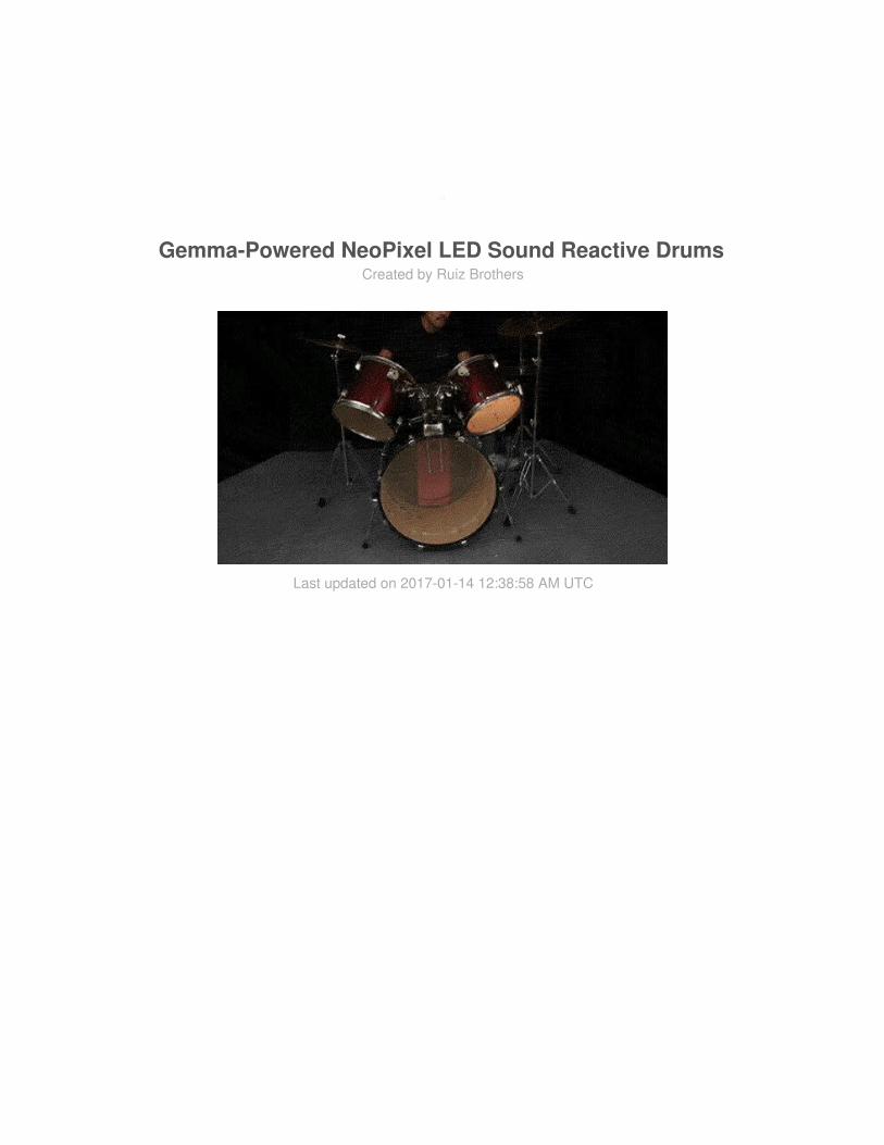
Gemma-Powered NeoPixel LED Sound Reactive DrumsCreated by Ruiz Brothers
Last updated on 2017-01-14 12:38:58 AM UTC
23444
556
101012
Guide Contents
Guide ContentsOverview
Prerequisite guidesTools & SuppliesParts
Circuit DiagramPrototype CircuitThe Code
3D PrintingPrinting TechniquesBuild
© Adafruit Industries https://learn.adafruit.com/gemma-powered-neopixel-led-sound-reactive-drums
Page 2 of 18
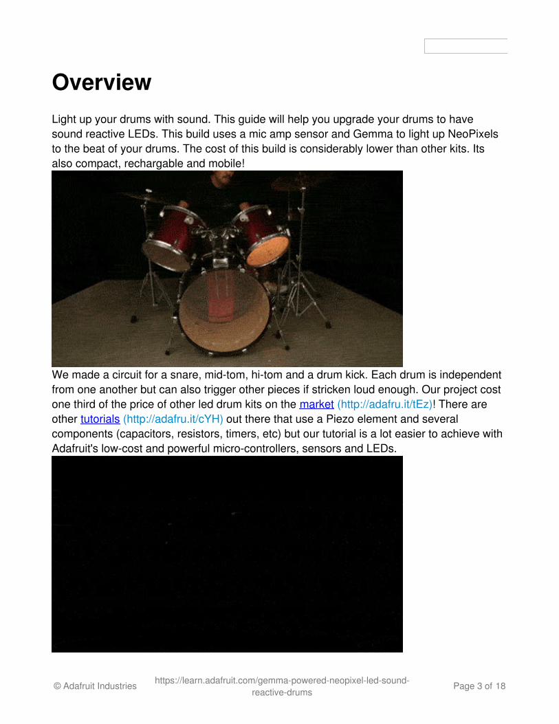
OverviewLight up your drums with sound. This guide will help you upgrade your drums to havesound reactive LEDs. This build uses a mic amp sensor and Gemma to light up NeoPixelsto the beat of your drums. The cost of this build is considerably lower than other kits. Itsalso compact, rechargable and mobile!
We made a circuit for a snare, mid-tom, hi-tom and a drum kick. Each drum is independentfrom one another but can also trigger other pieces if stricken loud enough. Our project costone third of the price of other led drum kits on the market (http://adafru.it/tEz)! There areother tutorials (http://adafru.it/cYH) out there that use a Piezo element and severalcomponents (capacitors, resistors, timers, etc) but our tutorial is a lot easier to achieve withAdafruit's low-cost and powerful micro-controllers, sensors and LEDs.
© Adafruit Industries https://learn.adafruit.com/gemma-powered-neopixel-led-sound-reactive-drums
Page 3 of 18
Prerequisite guides
NeoPixel Überguide (http://adafru.it/cEz) (http://adafru.it/cEz)Getting Started with G (http://adafru.it/cHH)emma (http://adafru.it/cHH)
Tools & Supplies
Soldering iron (http://adafru.it/caH)SolderScissors (http://adafru.it/1599)wire stripers (http://adafru.it/527)wire spool set (http://adafru.it/1311)Double sided foam tapePaper tape3D Printer (http://adafru.it/1292) (optional)
Parts
Drum SetGemma (http://adafru.it/1222)Mic Amp (http://adafru.it/1063)Slide Switch (http://adafru.it/805)Lithium Polymer Battery (http://adafru.it/1578)NeoPixel Strips (http://adafru.it/caH)
© Adafruit Industries https://learn.adafruit.com/gemma-powered-neopixel-led-sound-reactive-drums
Page 4 of 18
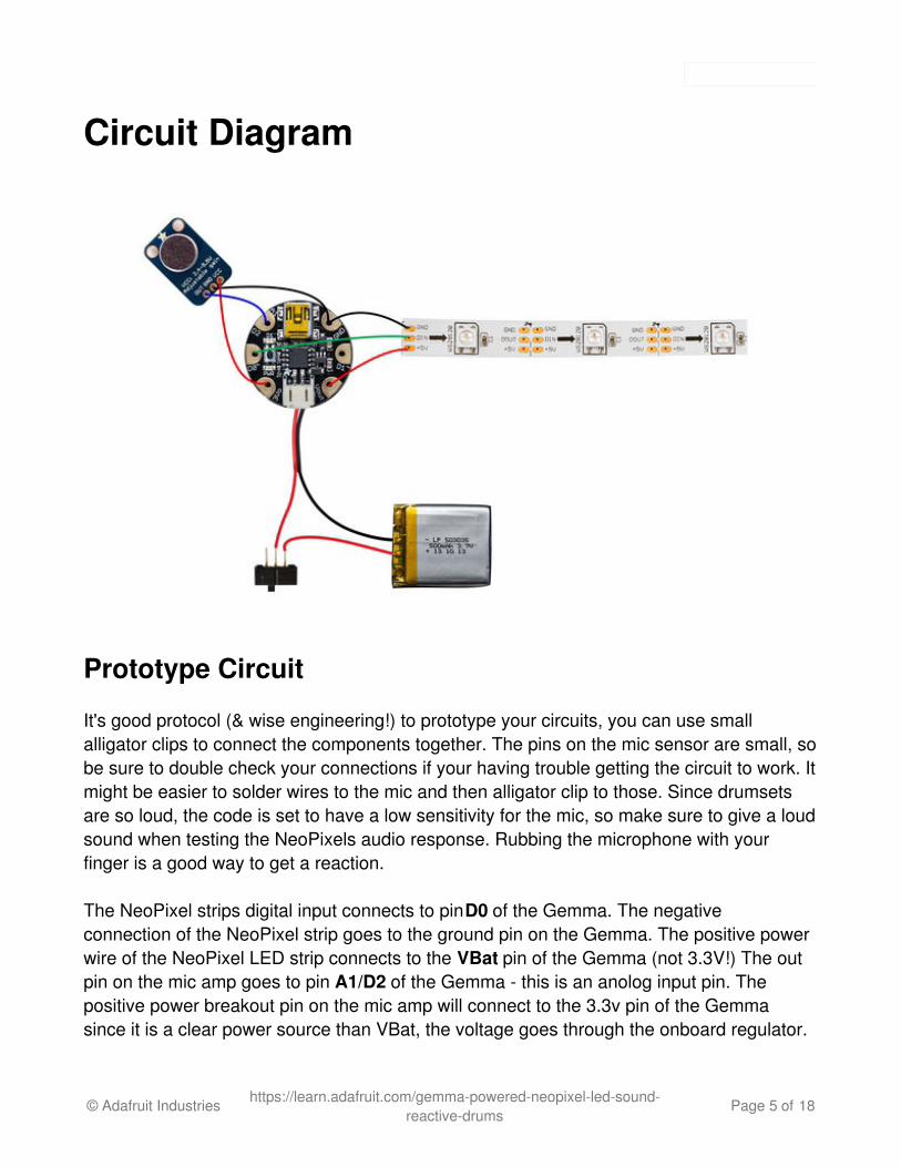
Circuit Diagram
Prototype Circuit
It's good protocol (& wise engineering!) to prototype your circuits, you can use smallalligator clips to connect the components together. The pins on the mic sensor are small, sobe sure to double check your connections if your having trouble getting the circuit to work. Itmight be easier to solder wires to the mic and then alligator clip to those. Since drumsetsare so loud, the code is set to have a low sensitivity for the mic, so make sure to give a loudsound when testing the NeoPixels audio response. Rubbing the microphone with yourfinger is a good way to get a reaction.
The NeoPixel strips digital input connects to pin D0 of the Gemma. The negativeconnection of the NeoPixel strip goes to the ground pin on the Gemma. The positive powerwire of the NeoPixel LED strip connects to the VBat pin of the Gemma (not 3.3V!) The outpin on the mic amp goes to pin A1/D2 of the Gemma - this is an anolog input pin. Thepositive power breakout pin on the mic amp will connect to the 3.3v pin of the Gemmasince it is a clear power source than VBat, the voltage goes through the onboard regulator.
© Adafruit Industries https://learn.adafruit.com/gemma-powered-neopixel-led-sound-reactive-drums
Page 5 of 18
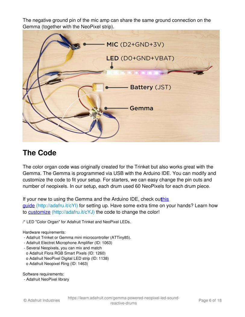
The negative ground pin of the mic amp can share the same ground connection on theGemma (together with the NeoPixel strip).
The Code
The color organ code was originally created for the Trinket but also works great with theGemma. The Gemma is programmed via USB with the Arduino IDE. You can modify andcustomize the code to fit your setup. For starters, we can easy change the pin outs andnumber of neopixels. In our setup, each drum used 60 NeoPixels for each drum piece.
If your new to using the Gemma and the Arduino IDE, check out thisguide (http://adafru.it/cYI) for setting up. Have some extra time on your hands? Learn howto customize (http://adafru.it/cYJ) the code to change the color!
/* LED "Color Organ" for Adafruit Trinket and NeoPixel LEDs.
Hardware requirements: - Adafruit Trinket or Gemma mini microcontroller (ATTiny85). - Adafruit Electret Microphone Amplifier (ID: 1063) - Several Neopixels, you can mix and match o Adafruit Flora RGB Smart Pixels (ID: 1260) o Adafruit NeoPixel Digital LED strip (ID: 1138) o Adafruit Neopixel Ring (ID: 1463)
Software requirements: - Adafruit NeoPixel library
© Adafruit Industries https://learn.adafruit.com/gemma-powered-neopixel-led-sound-reactive-drums
Page 6 of 18
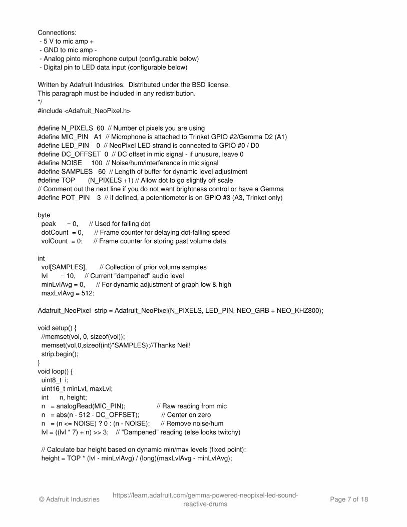
Connections: - 5 V to mic amp + - GND to mic amp - - Analog pinto microphone output (configurable below) - Digital pin to LED data input (configurable below)
Written by Adafruit Industries. Distributed under the BSD license.This paragraph must be included in any redistribution.*/#include <Adafruit_NeoPixel.h>
#define N_PIXELS 60 // Number of pixels you are using#define MIC_PIN A1 // Microphone is attached to Trinket GPIO #2/Gemma D2 (A1)#define LED_PIN 0 // NeoPixel LED strand is connected to GPIO #0 / D0#define DC_OFFSET 0 // DC offset in mic signal - if unusure, leave 0#define NOISE 100 // Noise/hum/interference in mic signal#define SAMPLES 60 // Length of buffer for dynamic level adjustment#define TOP (N_PIXELS +1) // Allow dot to go slightly off scale// Comment out the next line if you do not want brightness control or have a Gemma#define POT_PIN 3 // if defined, a potentiometer is on GPIO #3 (A3, Trinket only)
byte peak = 0, // Used for falling dot dotCount = 0, // Frame counter for delaying dot-falling speed volCount = 0; // Frame counter for storing past volume data int vol[SAMPLES], // Collection of prior volume samples lvl = 10, // Current "dampened" audio level minLvlAvg = 0, // For dynamic adjustment of graph low & high maxLvlAvg = 512;
Adafruit_NeoPixel strip = Adafruit_NeoPixel(N_PIXELS, LED_PIN, NEO_GRB + NEO_KHZ800);
void setup() { //memset(vol, 0, sizeof(vol)); memset(vol,0,sizeof(int)*SAMPLES);//Thanks Neil! strip.begin();}void loop() { uint8_t i; uint16_t minLvl, maxLvl; int n, height; n = analogRead(MIC_PIN); // Raw reading from mic n = abs(n - 512 - DC_OFFSET); // Center on zero n = (n <= NOISE) ? 0 : (n - NOISE); // Remove noise/hum lvl = ((lvl * 7) + n) >> 3; // "Dampened" reading (else looks twitchy) // Calculate bar height based on dynamic min/max levels (fixed point): height = TOP * (lvl - minLvlAvg) / (long)(maxLvlAvg - minLvlAvg);
© Adafruit Industries https://learn.adafruit.com/gemma-powered-neopixel-led-sound-reactive-drums
Page 7 of 18
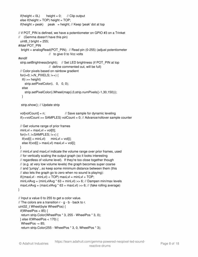
if(height < 0L) height = 0; // Clip output else if(height > TOP) height = TOP; if(height > peak) peak = height; // Keep 'peak' dot at top
// if POT_PIN is defined, we have a potentiometer on GPIO #3 on a Trinket // (Gemma doesn't have this pin) uint8_t bright = 255; #ifdef POT_PIN bright = analogRead(POT_PIN); // Read pin (0-255) (adjust potentiometer // to give 0 to Vcc volts#endif strip.setBrightness(bright); // Set LED brightness (if POT_PIN at top // define commented out, will be full) // Color pixels based on rainbow gradient for(i=0; i<N_PIXELS; i++) { if(i >= height) strip.setPixelColor(i, 0, 0, 0); else strip.setPixelColor(i,Wheel(map(i,0,strip.numPixels()-1,30,150))); }
strip.show(); // Update strip
vol[volCount] = n; // Save sample for dynamic leveling if(++volCount >= SAMPLES) volCount = 0; // Advance/rollover sample counter
// Get volume range of prior frames minLvl = maxLvl = vol[0]; for(i=1; i<SAMPLES; i++) { if(vol[i] < minLvl) minLvl = vol[i]; else if(vol[i] > maxLvl) maxLvl = vol[i]; } // minLvl and maxLvl indicate the volume range over prior frames, used // for vertically scaling the output graph (so it looks interesting // regardless of volume level). If they're too close together though // (e.g. at very low volume levels) the graph becomes super coarse // and 'jumpy'...so keep some minimum distance between them (this // also lets the graph go to zero when no sound is playing): if((maxLvl - minLvl) < TOP) maxLvl = minLvl + TOP; minLvlAvg = (minLvlAvg * 63 + minLvl) >> 6; // Dampen min/max levels maxLvlAvg = (maxLvlAvg * 63 + maxLvl) >> 6; // (fake rolling average)}
// Input a value 0 to 255 to get a color value.// The colors are a transition r - g - b - back to r.uint32_t Wheel(byte WheelPos) { if(WheelPos < 85) { return strip.Color(WheelPos * 3, 255 - WheelPos * 3, 0); } else if(WheelPos < 170) { WheelPos -= 85; return strip.Color(255 - WheelPos * 3, 0, WheelPos * 3);
© Adafruit Industries https://learn.adafruit.com/gemma-powered-neopixel-led-sound-reactive-drums
Page 8 of 18

} else { WheelPos -= 170; return strip.Color(0, WheelPos * 3, 255 - WheelPos * 3); }}
© Adafruit Industries https://learn.adafruit.com/gemma-powered-neopixel-led-sound-reactive-drums
Page 9 of 18
3D Printing
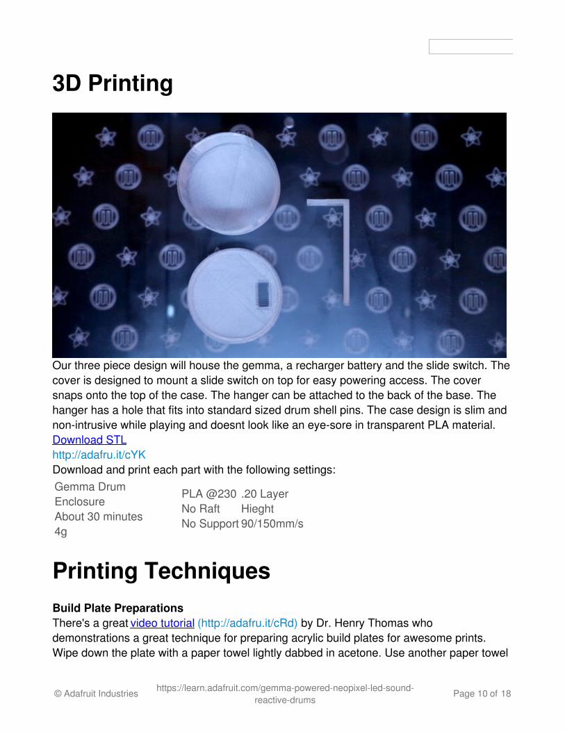
Our three piece design will house the gemma, a recharger battery and the slide switch. Thecover is designed to mount a slide switch on top for easy powering access. The coversnaps onto the top of the case. The hanger can be attached to the back of the base. Thehanger has a hole that fits into standard sized drum shell pins. The case design is slim andnon-intrusive while playing and doesnt look like an eye-sore in transparent PLA material.Download STLhttp://adafru.it/cYKDownload and print each part with the following settings:Gemma DrumEnclosureAbout 30 minutes4g
PLA @230No RaftNo Support
.20 LayerHieght90/150mm/s
Printing TechniquesBuild Plate PreparationsThere's a great video tutorial (http://adafru.it/cRd) by Dr. Henry Thomas whodemonstrations a great technique for preparing acrylic build plates for awesome prints.Wipe down the plate with a paper towel lightly dabbed in acetone. Use another paper towel
© Adafruit Industries https://learn.adafruit.com/gemma-powered-neopixel-led-sound-reactive-drums
Page 10 of 18
and apply a tiny dab of olive oil. Wipe down the plate so a small film of oil is applied, this willallow the parts to come off the plate easier.
Live LevelWe recommend going raft-less for each piece because it will have the best quality result.Each piece will require a well leveled platform. We tend to "live level" our prints, meaningwe adjust the build plates thumb screws while the print is laying down filament. This waywe can make adjustments directly and improve the leveling by seeing how the extrudersare laying down the first layer onto the build plate. We recommend watching the first layerso that you get a more successful print. If you see the layers aren't sticking or gettingknocked off, you can always cancel print, peel it off and try again.Once your pieces are printed, test out to see if the cover tightly snaps onto the case. Checkto see if the slide switch fit through the cutout on the cover. If its too tight, you can use an X-Acto knife to shave off the edges. If its too lose, you can secure it in place with adhesive.The hanger will be attached to the back of the case later with doubled-sided foam tape. Setthese pieces aside for now. It's time to solder some components!
© Adafruit Industries https://learn.adafruit.com/gemma-powered-neopixel-led-sound-reactive-drums
Page 11 of 18
Build
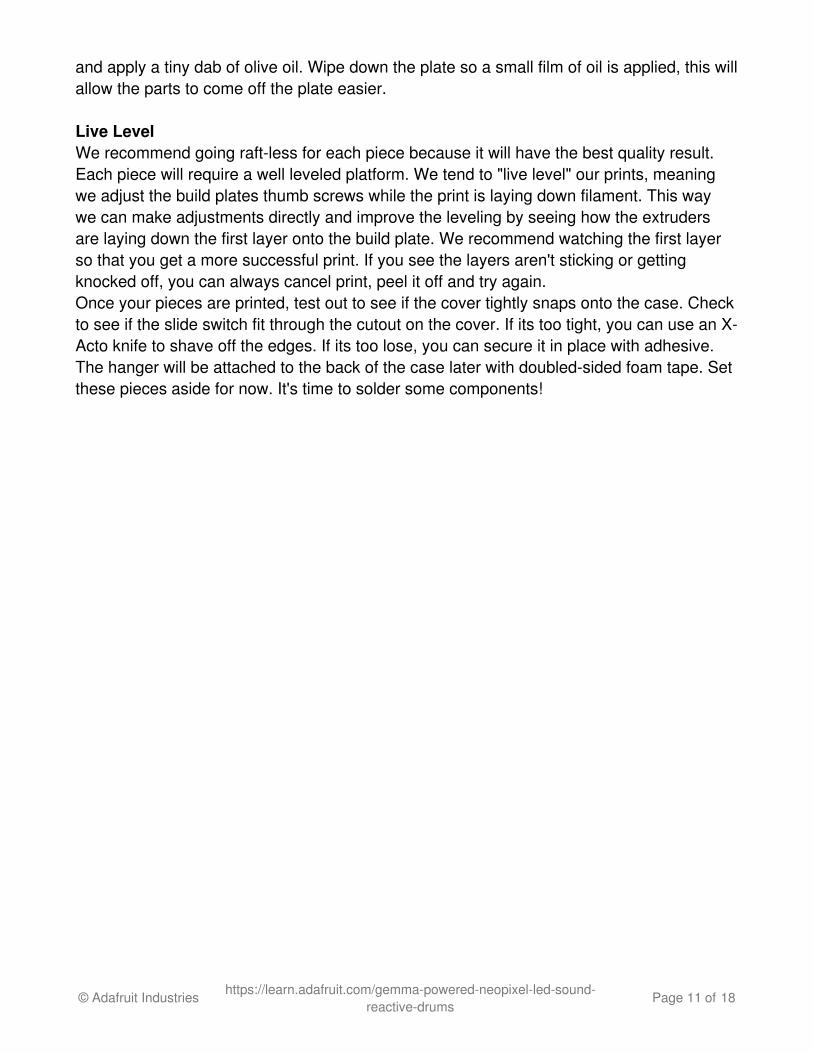
Once you have your circuit prototype tested and working, you will need to solder wires tothese components for a solid connection. You should start by measuring lengths of wiresneeded for connecting the Gemma to the NeoPixels and mic sensor. The wires should belong enough to run through the air hole and inside the drum shell. The main circuit (whichcontains the gemma, battery and switch) will be fitted inside an enclosure and mounted onthe side of the drum shell closest to the air hole. To see if your wires are long enough,place the Gemma into position and see if the wire is long enough to connect the NeoPixelstrips inside the drum shell. It's fine to have some extra wire.
© Adafruit Industries https://learn.adafruit.com/gemma-powered-neopixel-led-sound-reactive-drums
Page 12 of 18
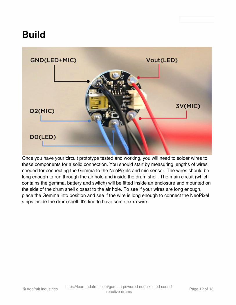
The NeoPixel strip will need three wires soldered to the beginning of the pixel strip. Soldera black wire to the GND pin. A blue wire to the DIN pin. And a red wire to the positive +5Vpin. The length of these three wires can be short because we can use alligator clips toconnect them to the longer wires that will be soldered to the Gemma.
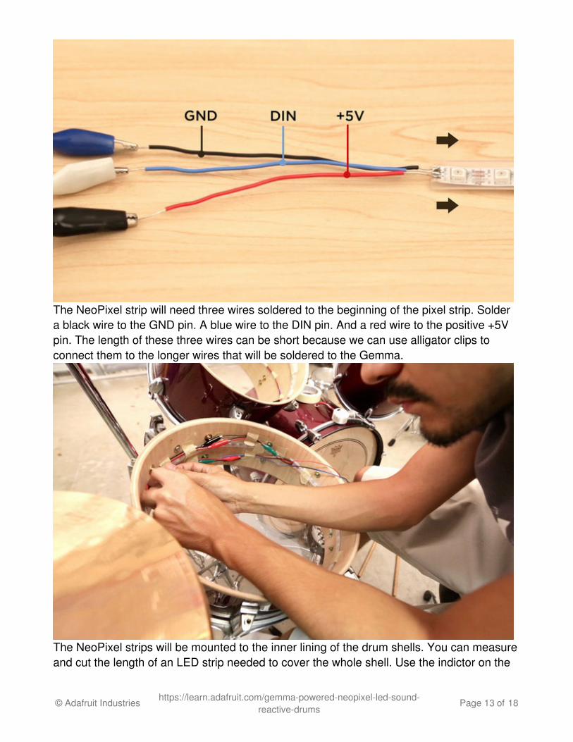
The NeoPixel strips will be mounted to the inner lining of the drum shells. You can measureand cut the length of an LED strip needed to cover the whole shell. Use the indictor on the
© Adafruit Industries https://learn.adafruit.com/gemma-powered-neopixel-led-sound-reactive-drums
Page 13 of 18
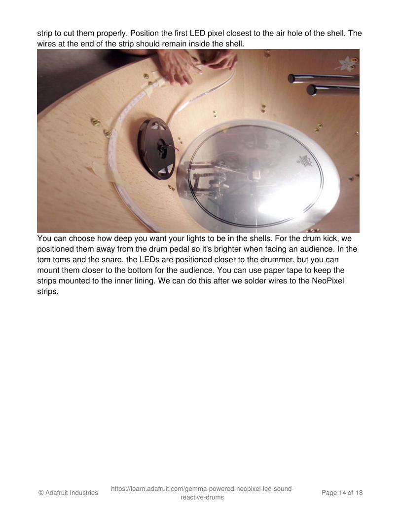
strip to cut them properly. Position the first LED pixel closest to the air hole of the shell. Thewires at the end of the strip should remain inside the shell.
You can choose how deep you want your lights to be in the shells. For the drum kick, wepositioned them away from the drum pedal so it's brighter when facing an audience. In thetom toms and the snare, the LEDs are positioned closer to the drummer, but you canmount them closer to the bottom for the audience. You can use paper tape to keep thestrips mounted to the inner lining. We can do this after we solder wires to the NeoPixelstrips.
© Adafruit Industries https://learn.adafruit.com/gemma-powered-neopixel-led-sound-reactive-drums
Page 14 of 18
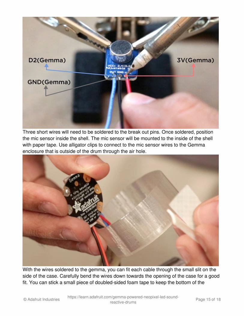
Three short wires will need to be soldered to the break out pins. Once soldered, positionthe mic sensor inside the shell. The mic sensor will be mounted to the inside of the shellwith paper tape. Use alligator clips to connect to the mic sensor wires to the Gemmaenclosure that is outside of the drum through the air hole.
With the wires soldered to the gemma, you can fit each cable through the small slit on theside of the case. Carefully bend the wires down towards the opening of the case for a goodfit. You can stick a small piece of doubled-sided foam tape to keep the bottom of the
© Adafruit Industries https://learn.adafruit.com/gemma-powered-neopixel-led-sound-reactive-drums
Page 15 of 18
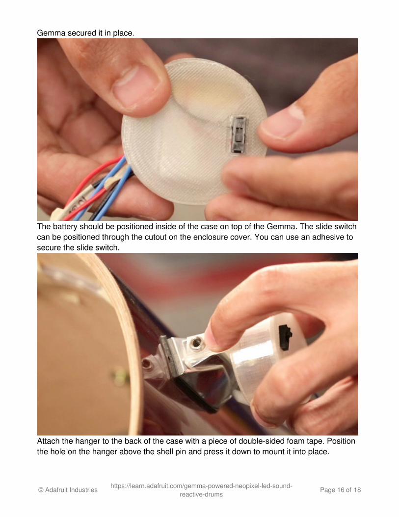
Gemma secured it in place.
The battery should be positioned inside of the case on top of the Gemma. The slide switchcan be positioned through the cutout on the enclosure cover. You can use an adhesive tosecure the slide switch.
Attach the hanger to the back of the case with a piece of double-sided foam tape. Positionthe hole on the hanger above the shell pin and press it down to mount it into place.
© Adafruit Industries https://learn.adafruit.com/gemma-powered-neopixel-led-sound-reactive-drums
Page 16 of 18
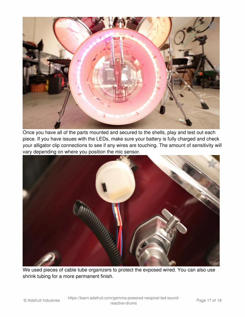
Once you have all of the parts mounted and secured to the shells, play and test out eachpiece. If you have issues with the LEDs, make sure your battery is fully charged and checkyour alligator clip connections to see if any wires are touching. The amount of sensitivity willvary depending on where you position the mic sensor.
We used pieces of cable tube organizers to protect the exposed wired. You can also useshrink tubing for a more permanent finish.
© Adafruit Industries https://learn.adafruit.com/gemma-powered-neopixel-led-sound-reactive-drums
Page 17 of 18

The lithium polymer batteries can be removed and recharged. They should last about anhours worth of play time. You can alternatively use a bigger battery pack for a longersessions. The cases are non-intrsutive to the look of the drums and the wires and sensorinside the shells don't have an overall change to the sound. Since each drum isindependent of each other, you can break down your set without having to worry aboutdisconnecting any wires!
Made an awesome upgrade? Let us know!! Stop by our weekly show-n-tell onyoutube (http://adafru.it/cYL), Saturdays at 9:30 PM EST and show off your upgrade toLady Ada her self (and thousands of people LIVE) also WIN a FREE As Seen on Show-N-Tell Adafruit sticker! Post a comment on our google+ (http://adafru.it/tEA) page in our showrelated post and we'll invite you!
© Adafruit Industries Last Updated: 2017-01-14 12:38:57 AM UTC Page 18 of 18