Embed Size (px)
Citation preview
1
Geiger-Lund model 2019 Selective Asparagus Harvester
Owner’s/Operators’ Manual
Model 2019 Geiger-Lund Harvesters LLC 1110 E. Scotts Ave. Stockton, California USA 95205 www.asparagusharvester.com Ph. 209 464-7746
2
Introduction ……………………………………………………………………………….3 Safety Rules………….……………………………………………………………………..5 Specifications ……………………………………………………………………………..7 Theory of operation ……………………………………………………………………8 Speedometer ...……………………………..…………………………………10 Spear sensor ……………………………………………………………………11 Pickup units ………………………………………………………….………...12 Cutting Cylinders ………………………………………………….………….15 Drop Bar.……………………………………………………….………………..17 Conveyor …………………………………………………………….…………..18 Backstop …………………………………………………………………….……19 Box Filling ………………………………………………………………………..20 Hydraulic System ……………………………………………………………………….21 Compressed Air System ……………………………………………………………..22 Cutting Valve Assemblies ……………………………………………………………23 Hydraulic Controls ……………………………………………………………………..24 Electronic Stroke Control …………………………………………………………..25 Mechanical Adjustments ...…………………………………………………………27 Maintenance ………………………………………………………………………………28 Initial Machine Checkout and Set Up ………………………………………….29 Harvesting ………………………………………………………………………………….31 Parts Locator……………………………………………………………………………….32
3
INTRODUCTION THANK YOU for purchasing a Geiger-Lund model 2019 selective asparagus harvester. NOTE: This manual contains information on the Geiger-Lund asparagus harvester. Carefully read this manual before attempting to operate or perform maintenance on the machine. Also read the manual for the air compressor included with this machine.
This manual does not cover the air compressor. Please read the air compressor owner’s manual before using this asparagus harvester. The air compressor manual is included with this manual.
Keep both manuals handy for reference. The Geiger-Lund model 2019 is a single row selective asparagus harvester for selectively harvesting green asparagus spears. The machine can be adjusted for a cut length of 8, 9, or 10 inches. (All green spear) The cut is at ground level. We estimate the yield to be 70% to 80% or more. The machine is very simple which makes it very easy to operate, maintain, and repair. There are few moving parts, and they are easy to repair if ever needed. The only maintenance is servicing of the air compressor and the daily draining of the water from the air system. This machine works in a way that is similar to how humans cut asparagus. It has “eyes” that it uses to find the harvestable spears. It has “fingers” that pull up on the spear just before it is cut. It has a knife identical to what humans use and it jabs the knife into the soil the way a human does it. It’s like a human that has eight arms with knives and eight more arms for picking up the spears! The machine puts the spears in the box the same way the hand laborers would do it, (all lined up pointing the same direction).

4
Setup is easy… Just hitch the machine to a tractor, connect the electric and hydraulic lines and set the machine height and adjust the cutter stroke length. You’re ready to harvest! For best results, the asparagus beds should be flat and level and the furrows on either side of the bed should be at the same depth so the machine does not tilt to either side. Flat ground is ideal.
5
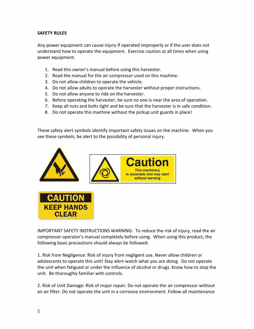
SAFETY RULES Any power equipment can cause injury if operated improperly or if the user does not understand how to operate the equipment. Exercise caution at all times when using power equipment.
1. Read this owner’s manual before using this harvester. 2. Read the manual for the air compressor used on this machine. 3. Do not allow children to operate the vehicle. 4. Do not allow adults to operate the harvester without proper instructions. 5. Do not allow anyone to ride on the harvester. 6. Before operating the harvester, be sure no one is near the area of operation. 7. Keep all nuts and bolts tight and be sure that the harvester is in safe condition. 8. Do not operate this machine without the pickup unit guards in place!
These safety alert symbols identify important safety issues on the machine. When you see these symbols, be alert to the possibility of personal injury.
IMPORTANT SAFETY INSTRUCTIONS WARNING: To reduce the risk of injury, read the air compressor operator’s manual completely before using. When using this product, the following basic precautions should always be followed: 1. Risk from Negligence: Risk of injury from negligent use. Never allow children or adolescents to operate this unit! Stay alert-watch what you are doing. Do not operate the unit when fatigued or under the influence of alcohol or drugs. Know how to stop the unit. Be thoroughly familiar with controls. 2. Risk of Unit Damage: Risk of major repair. Do not operate the air compressor without an air filter. Do not operate the unit in a corrosive environment. Follow all maintenance
6
instructions listed in this manual. 3. When starting the air compressor, using recoil starter grip, be sure that nothing is in a position to be hit by the operator’s hand or arm. 4. Avoid contacting the hot exhaust manifold, muffler or cylinder(s). 6. Keep clear of all rotating and reciprocating parts. 7. Beware of using this equipment in confined spaces. Confined spaces, without sufficient fresh air ventilation, can contain dangerous gases. Running diesel engines in such environments can lead to deadly explosions and/or asphyxiation. Keep your hands and other body parts away from the cutting blades. The blades are sharp, and quick. If the power is turned on any blade could fire at any time unexpectedly so keep your body parts away from the cutting area at the rear of the pickup rollers if there is air pressure in the system. Before performing any work or maintenance on any part of the compressed air system, or near the cutting blades, open the drain valves to bleed the air from the system and allow it to reach zero pressure.
Learn how to stop the tractor engine suddenly in an emergency. Never allow inexperienced or untrained personnel to operate the Tractor and harvester without supervision. Make sure the operator has fully read and understood the manuals prior to operation. WARNING! Do not modify or alter this machine. Do not permit anyone to modify or alter this machine, any of its components or any of its functions.
7
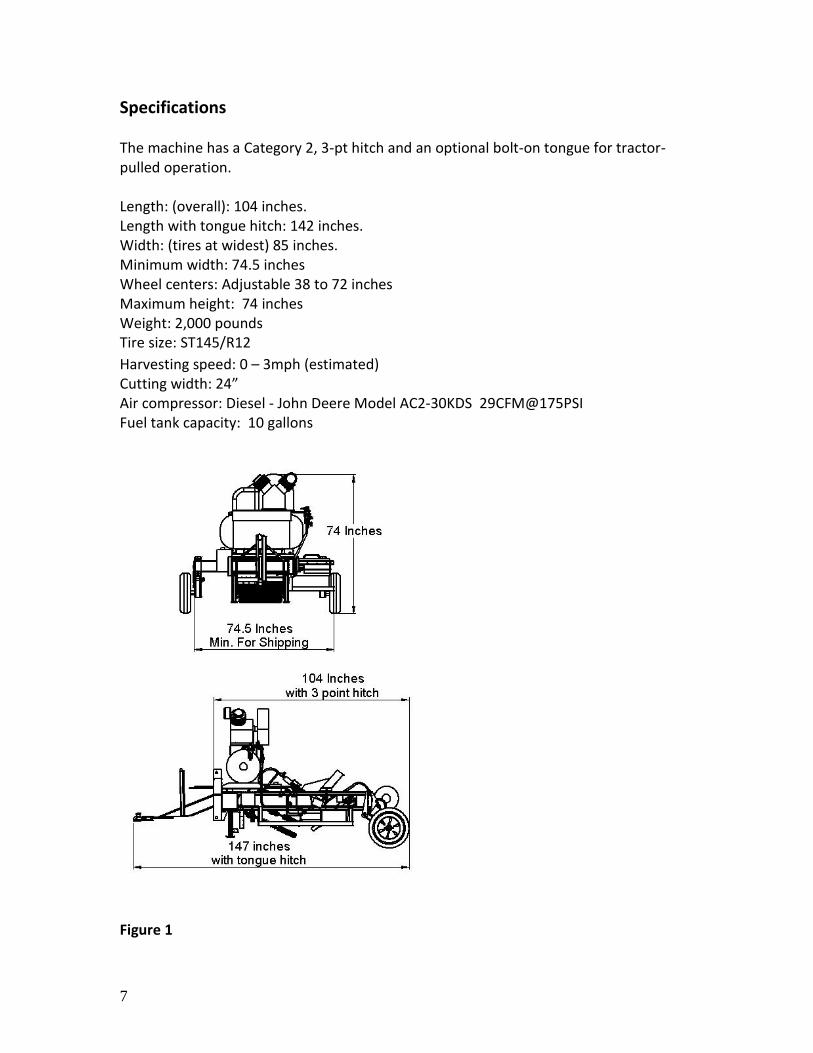
Specifications The machine has a Category 2, 3-pt hitch and an optional bolt-on tongue for tractor-pulled operation. Length: (overall): 104 inches. Length with tongue hitch: 142 inches. Width: (tires at widest) 85 inches. Minimum width: 74.5 inches Wheel centers: Adjustable 38 to 72 inches Maximum height: 74 inches Weight: 2,000 pounds Tire size: ST145/R12
Harvesting speed: 0 – 3mph (estimated) Cutting width: 24” Air compressor: Diesel - John Deere Model AC2-30KDS 29CFM@175PSI Fuel tank capacity: 10 gallons
Figure 1
8
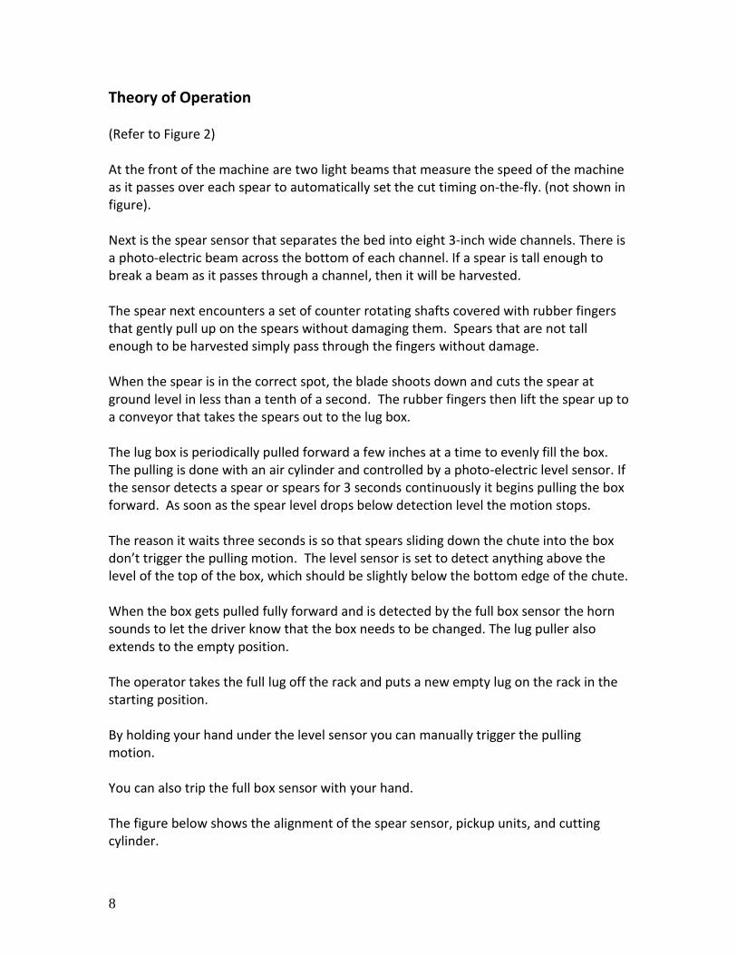
Theory of Operation
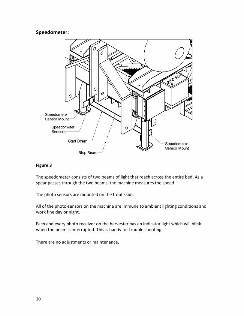
(Refer to Figure 2) At the front of the machine are two light beams that measure the speed of the machine as it passes over each spear to automatically set the cut timing on-the-fly. (not shown in figure). Next is the spear sensor that separates the bed into eight 3-inch wide channels. There is a photo-electric beam across the bottom of each channel. If a spear is tall enough to break a beam as it passes through a channel, then it will be harvested. The spear next encounters a set of counter rotating shafts covered with rubber fingers that gently pull up on the spears without damaging them. Spears that are not tall enough to be harvested simply pass through the fingers without damage. When the spear is in the correct spot, the blade shoots down and cuts the spear at ground level in less than a tenth of a second. The rubber fingers then lift the spear up to a conveyor that takes the spears out to the lug box. The lug box is periodically pulled forward a few inches at a time to evenly fill the box. The pulling is done with an air cylinder and controlled by a photo-electric level sensor. If the sensor detects a spear or spears for 3 seconds continuously it begins pulling the box forward. As soon as the spear level drops below detection level the motion stops. The reason it waits three seconds is so that spears sliding down the chute into the box don’t trigger the pulling motion. The level sensor is set to detect anything above the level of the top of the box, which should be slightly below the bottom edge of the chute. When the box gets pulled fully forward and is detected by the full box sensor the horn sounds to let the driver know that the box needs to be changed. The lug puller also extends to the empty position. The operator takes the full lug off the rack and puts a new empty lug on the rack in the starting position. By holding your hand under the level sensor you can manually trigger the pulling motion. You can also trip the full box sensor with your hand. The figure below shows the alignment of the spear sensor, pickup units, and cutting cylinder.
9
Figure 2
10
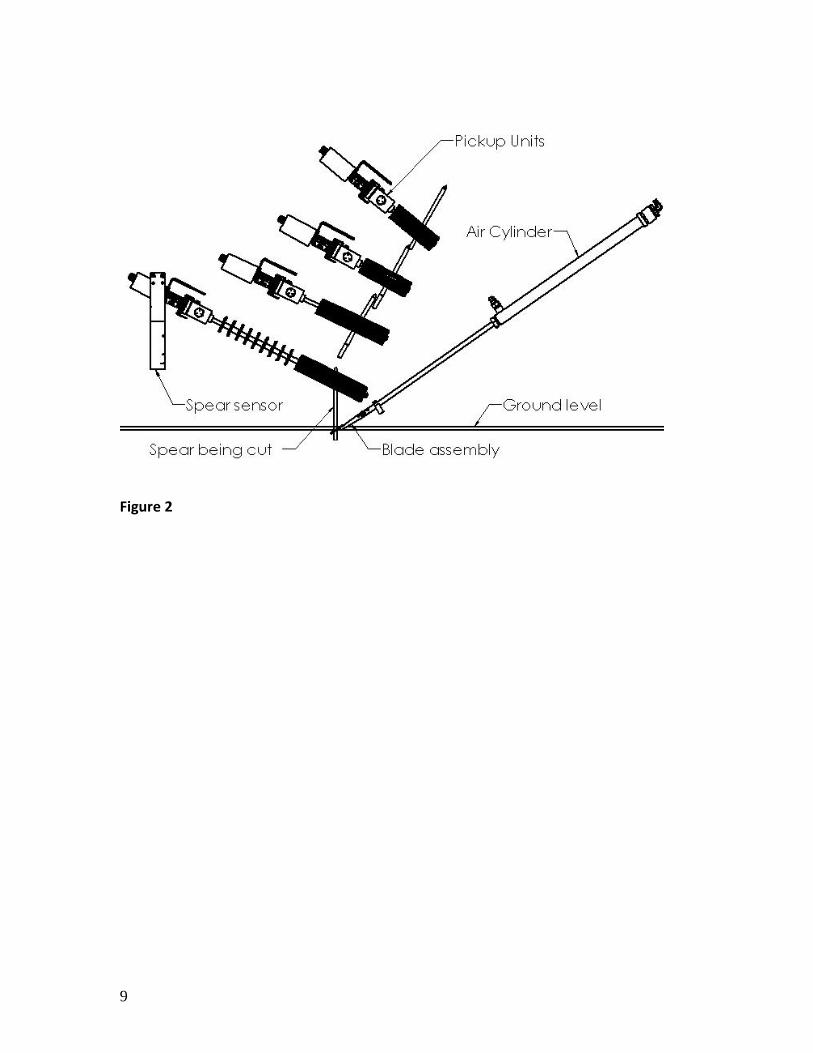
Speedometer:
Figure 3 The speedometer consists of two beams of light that reach across the entire bed. As a spear passes through the two beams, the machine measures the speed. The photo sensors are mounted on the front skids. All of the photo-sensors on the machine are immune to ambient lighting conditions and work fine day or night. Each and every photo receiver on the harvester has an indicator light which will blink when the beam is interrupted. This is handy for trouble shooting.
There are no adjustments or maintenance.
11
Spear sensor:
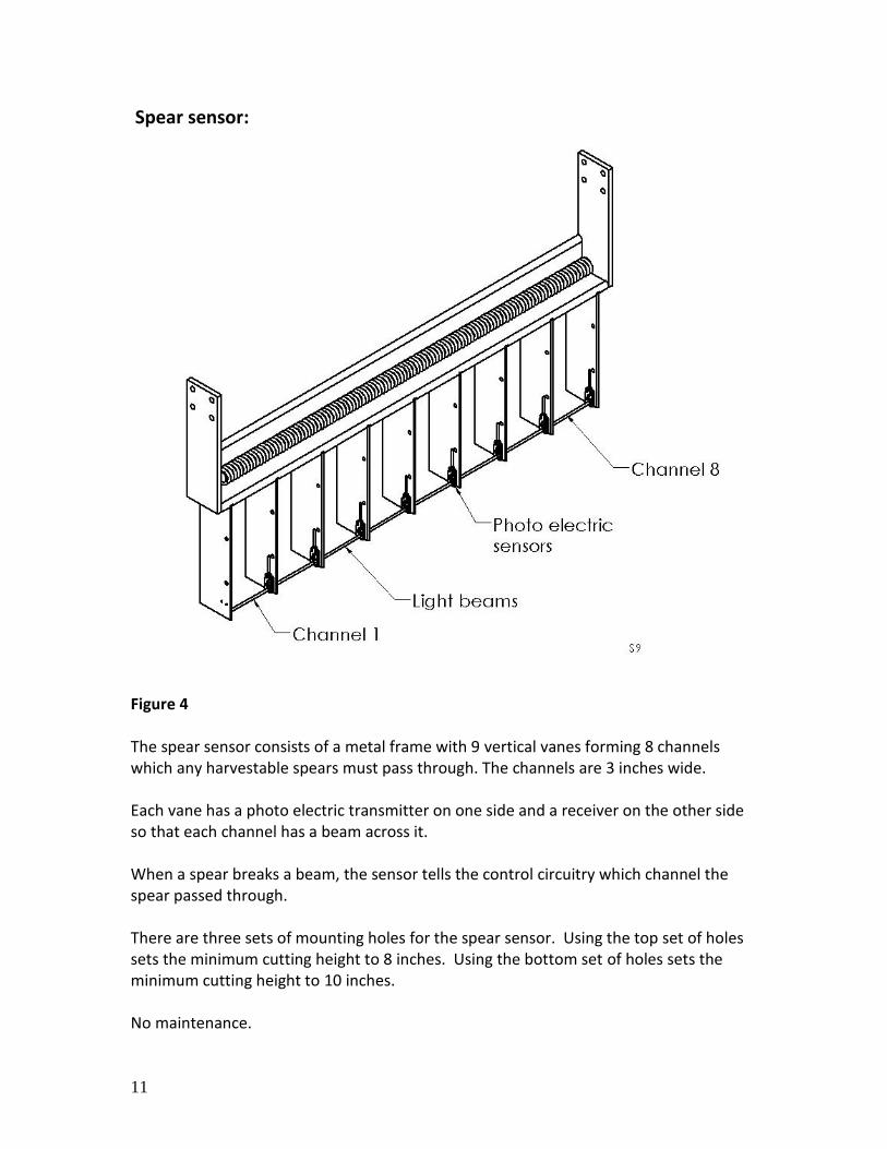
Figure 4 The spear sensor consists of a metal frame with 9 vertical vanes forming 8 channels which any harvestable spears must pass through. The channels are 3 inches wide. Each vane has a photo electric transmitter on one side and a receiver on the other side so that each channel has a beam across it. When a spear breaks a beam, the sensor tells the control circuitry which channel the spear passed through. There are three sets of mounting holes for the spear sensor. Using the top set of holes sets the minimum cutting height to 8 inches. Using the bottom set of holes sets the minimum cutting height to 10 inches. No maintenance.
12
Pickup units:
Figure 5
13
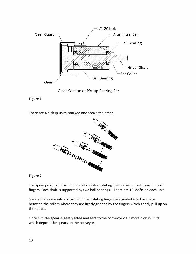
Figure 6 There are 4 pickup units, stacked one above the other.
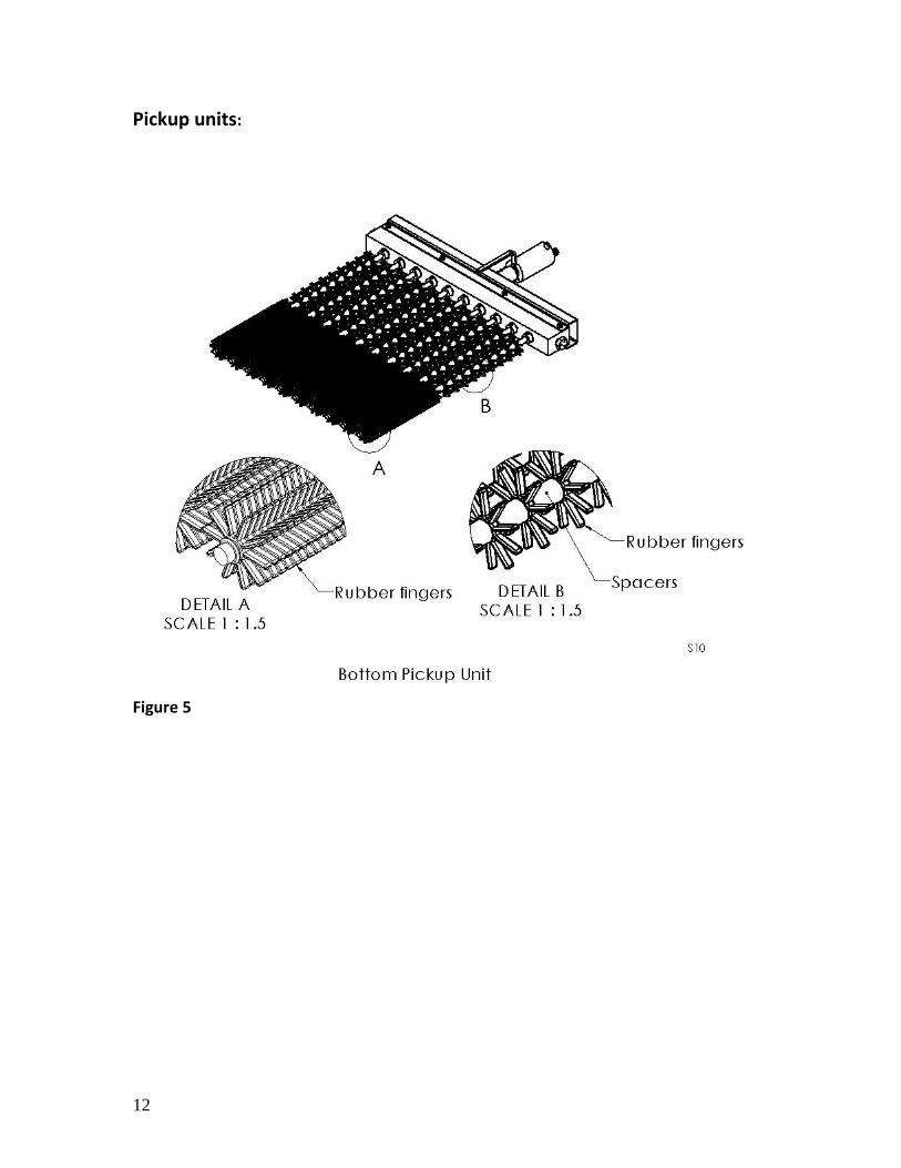
Figure 7 The spear pickups consist of parallel counter-rotating shafts covered with small rubber fingers. Each shaft is supported by two ball bearings. There are 10 shafts on each unit. Spears that come into contact with the rotating fingers are guided into the space between the rollers where they are lightly gripped by the fingers which gently pull up on the spears. Once cut, the spear is gently lifted and sent to the conveyor via 3 more pickup units which deposit the spears on the conveyor.

14
On the upper portion of the shaft on the bottom pickup unit the fingers are spaced apart and only serve to guide the taller spears into the proper channels, not lift up on them. A small hydraulic motor is mounted on one of the shafts on each pickup unit. The motors are all connected in series so that all the pickup rollers run at the same rpm. The top pickup unit has a flow control for adjusting the rpm of the shafts. The angle of the pickup units can be adjusted by loosening the two mounting bolts on either end of the unit, changing the angle, and re-tightening the mounting bolts. Over time the rubber fingers will wear out. This occurs primarily on the center section of the bottom pickup unit. Since spears that are slightly too short to harvest are still long enough to be pulled on by the fingers, wear does occur due to friction between the spear and finger. The top 3 pickup units probably won’t experience any significant wear since the spears they come in contact aren’t being pulled out of the fingers. Since there is little if any slippage there is little to no wear on the fingers. If you begin experiencing spears being cut but not picked up, then check the wear on those fingers.
15
Cutting Cylinders:
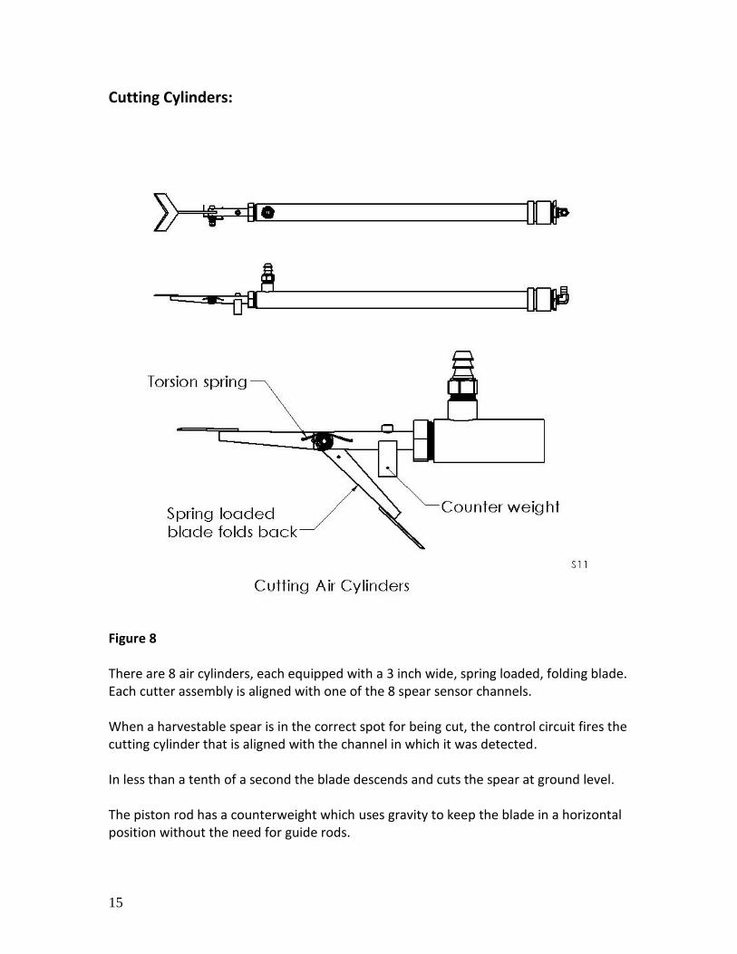
Figure 8 There are 8 air cylinders, each equipped with a 3 inch wide, spring loaded, folding blade. Each cutter assembly is aligned with one of the 8 spear sensor channels. When a harvestable spear is in the correct spot for being cut, the control circuit fires the cutting cylinder that is aligned with the channel in which it was detected. In less than a tenth of a second the blade descends and cuts the spear at ground level. The piston rod has a counterweight which uses gravity to keep the blade in a horizontal position without the need for guide rods.

16
The cylinders are permanently lubricated and need no maintenance. The cylinders are super rugged, having a ¼” thick cylinder wall, oversized 5/8” diameter hard chrome plated high yield strength alloy steel. The openings in the cylinder ends are 1” NPT tapered pipe threads so no seals or gaskets are needed. Disassembly and reassembly is quick and easy. The cylinder can be re-built on or off the machine in less than 15 minutes. The cylinders drop into their mounts and there are no bolts to deal with. Just lift it out and or drop it in. You do have to remove the hoses with a wrench. Sigh. No adjustments and no maintenance.
17
Drop bar:
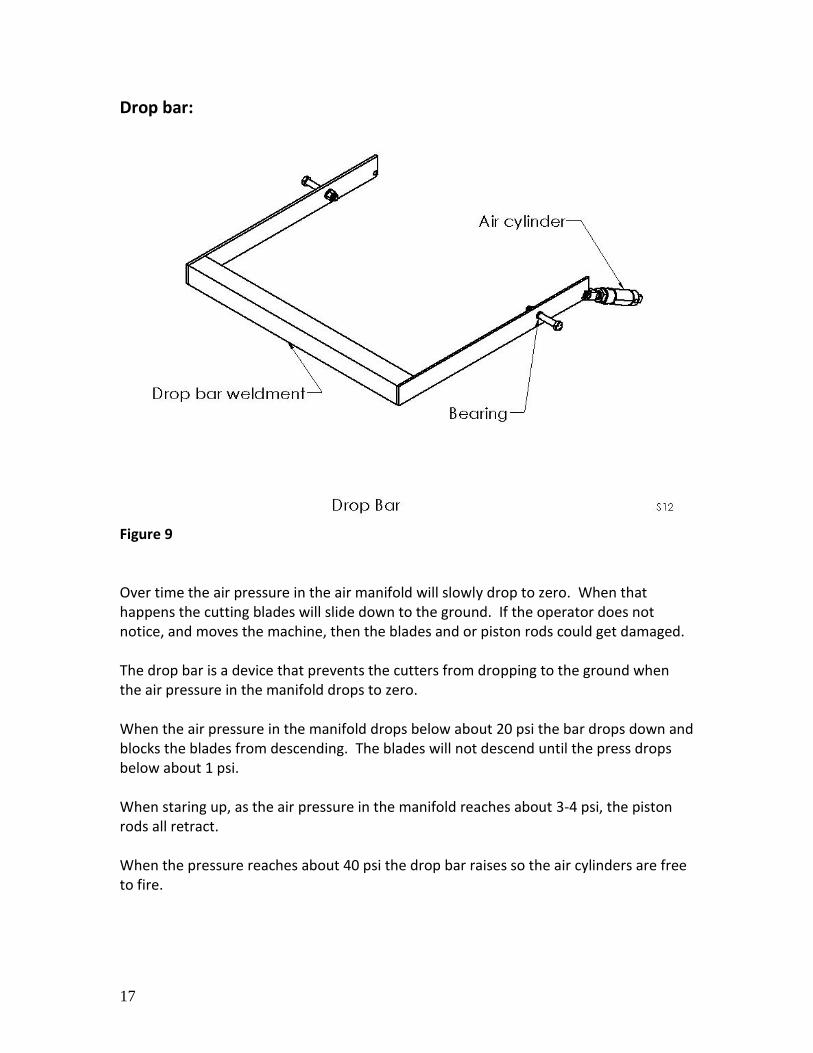
Figure 9 Over time the air pressure in the air manifold will slowly drop to zero. When that happens the cutting blades will slide down to the ground. If the operator does not notice, and moves the machine, then the blades and or piston rods could get damaged. The drop bar is a device that prevents the cutters from dropping to the ground when the air pressure in the manifold drops to zero. When the air pressure in the manifold drops below about 20 psi the bar drops down and blocks the blades from descending. The blades will not descend until the press drops below about 1 psi. When staring up, as the air pressure in the manifold reaches about 3-4 psi, the piston rods all retract. When the pressure reaches about 40 psi the drop bar raises so the air cylinders are free to fire.
18
Conveyor:
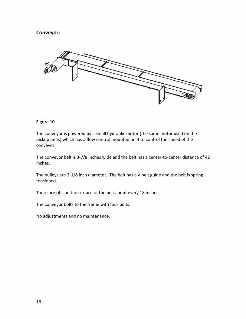
Figure 10 The conveyor is powered by a small hydraulic motor (the same motor used on the pickup units) which has a flow control mounted on it to control the speed of the conveyor. The conveyor belt is 3-7/8 inches wide and the belt has a center-to-center distance of 42 inches. The pulleys are 2-1/8 inch diameter. The belt has a v-belt guide and the belt is spring tensioned. There are ribs on the surface of the belt about every 18 inches. The conveyor bolts to the frame with four bolts. No adjustments and no maintenance.
19
Backstop:
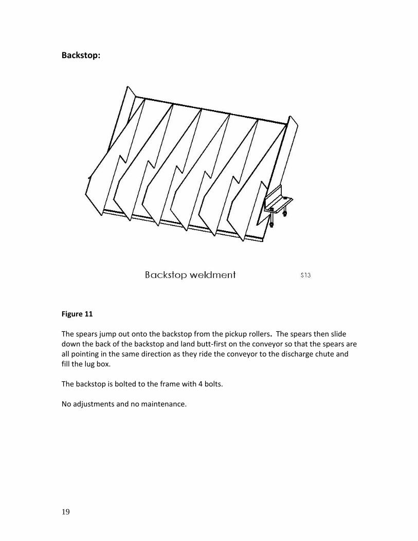
Figure 11 The spears jump out onto the backstop from the pickup rollers. The spears then slide down the back of the backstop and land butt-first on the conveyor so that the spears are all pointing in the same direction as they ride the conveyor to the discharge chute and fill the lug box. The backstop is bolted to the frame with 4 bolts. No adjustments and no maintenance.
20
Box filling:
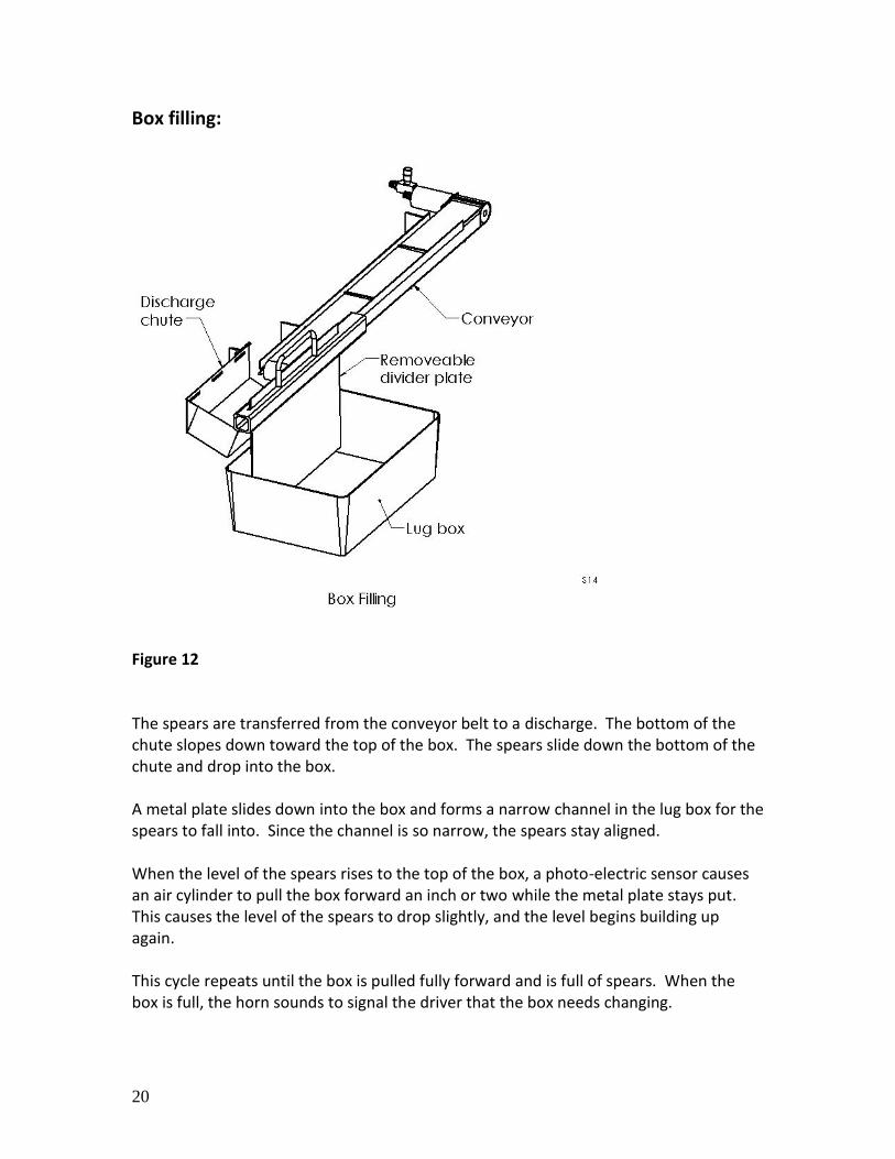
Figure 12 The spears are transferred from the conveyor belt to a discharge. The bottom of the chute slopes down toward the top of the box. The spears slide down the bottom of the chute and drop into the box. A metal plate slides down into the box and forms a narrow channel in the lug box for the spears to fall into. Since the channel is so narrow, the spears stay aligned. When the level of the spears rises to the top of the box, a photo-electric sensor causes an air cylinder to pull the box forward an inch or two while the metal plate stays put. This causes the level of the spears to drop slightly, and the level begins building up again. This cycle repeats until the box is pulled fully forward and is full of spears. When the box is full, the horn sounds to signal the driver that the box needs changing.
21
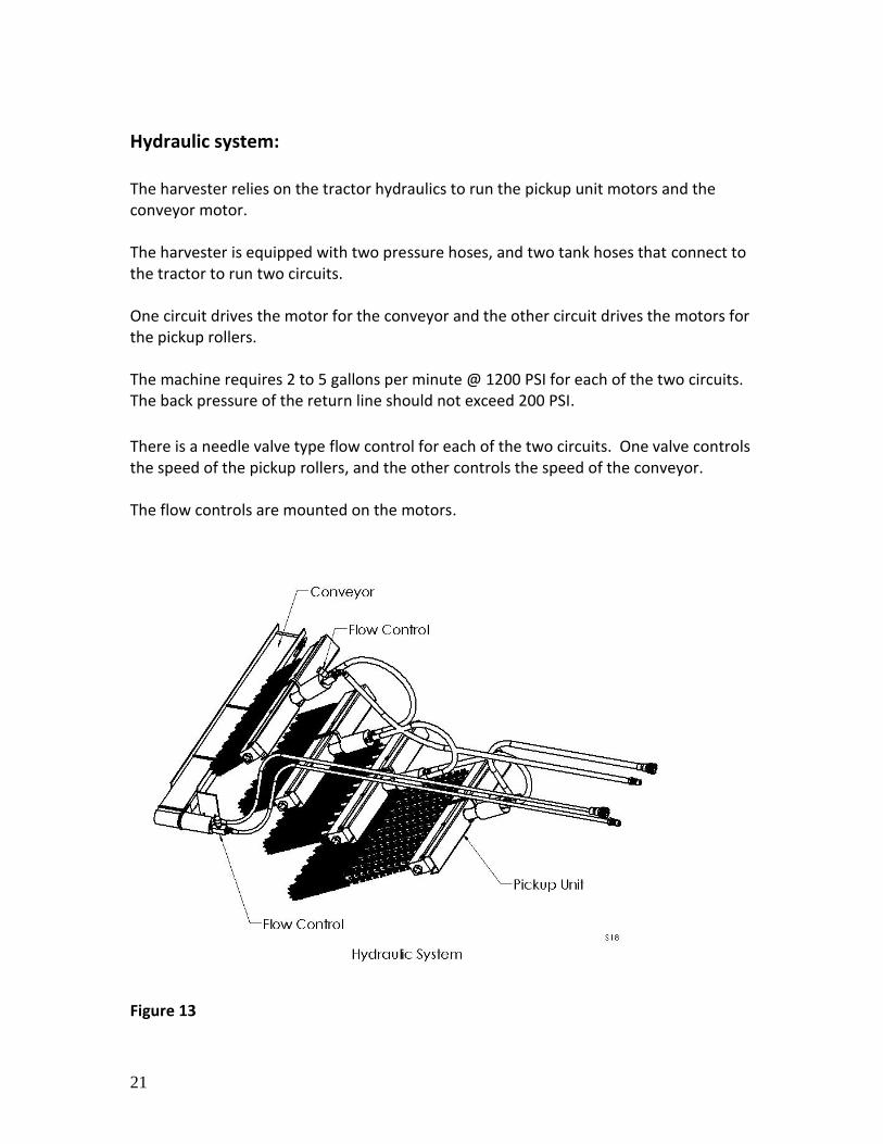
Hydraulic system: The harvester relies on the tractor hydraulics to run the pickup unit motors and the conveyor motor. The harvester is equipped with two pressure hoses, and two tank hoses that connect to the tractor to run two circuits. One circuit drives the motor for the conveyor and the other circuit drives the motors for the pickup rollers. The machine requires 2 to 5 gallons per minute @ 1200 PSI for each of the two circuits. The back pressure of the return line should not exceed 200 PSI.
There is a needle valve type flow control for each of the two circuits. One valve controls the speed of the pickup rollers, and the other controls the speed of the conveyor. The flow controls are mounted on the motors.
Figure 13
22
Compressed Air System:
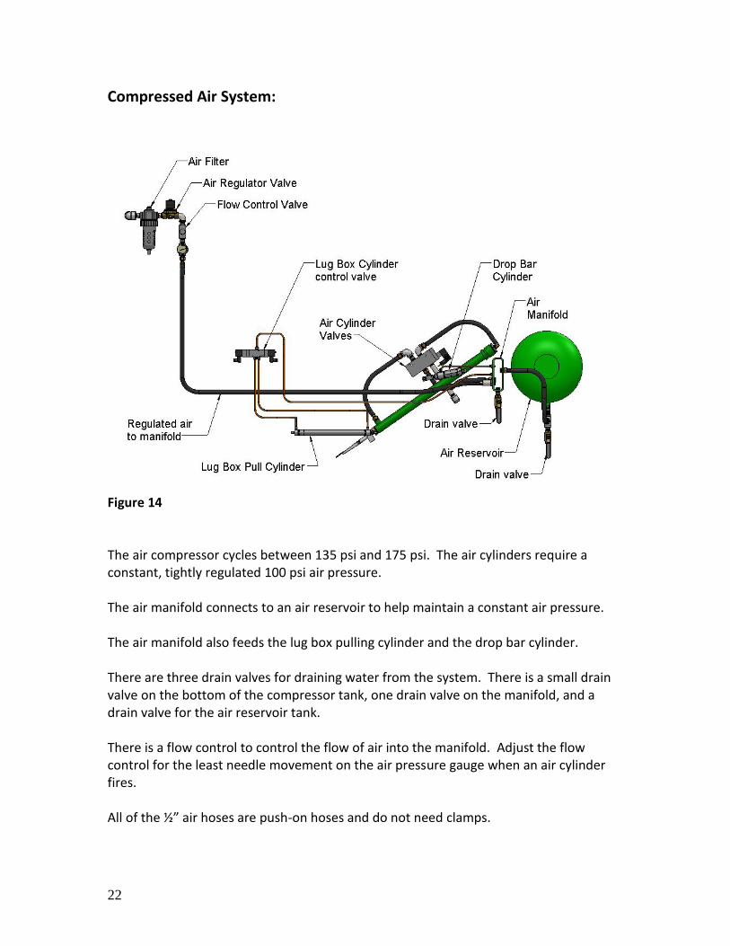
Figure 14 The air compressor cycles between 135 psi and 175 psi. The air cylinders require a constant, tightly regulated 100 psi air pressure. The air manifold connects to an air reservoir to help maintain a constant air pressure. The air manifold also feeds the lug box pulling cylinder and the drop bar cylinder. There are three drain valves for draining water from the system. There is a small drain valve on the bottom of the compressor tank, one drain valve on the manifold, and a drain valve for the air reservoir tank. There is a flow control to control the flow of air into the manifold. Adjust the flow control for the least needle movement on the air pressure gauge when an air cylinder fires. All of the ½” air hoses are push-on hoses and do not need clamps.
23
Cutting Air Valve Assembly
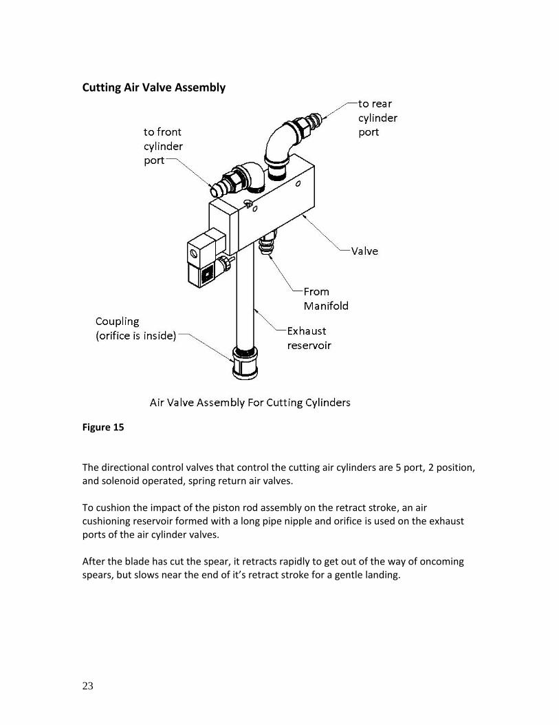
Figure 15 The directional control valves that control the cutting air cylinders are 5 port, 2 position, and solenoid operated, spring return air valves. To cushion the impact of the piston rod assembly on the retract stroke, an air cushioning reservoir formed with a long pipe nipple and orifice is used on the exhaust ports of the air cylinder valves. After the blade has cut the spear, it retracts rapidly to get out of the way of oncoming spears, but slows near the end of it’s retract stroke for a gentle landing.
24
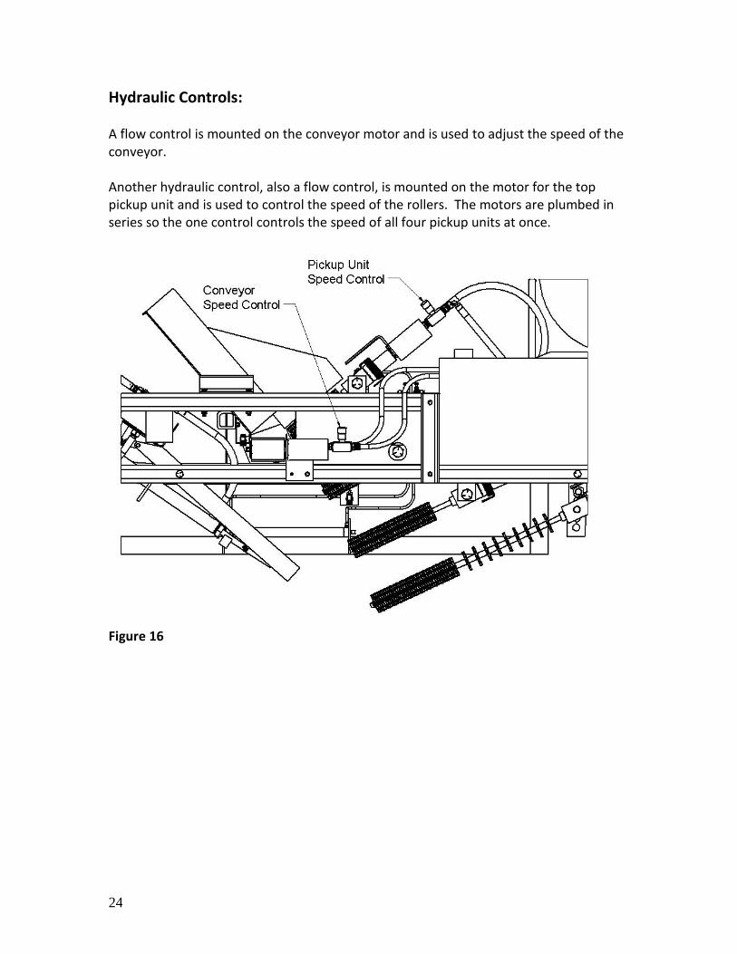
Hydraulic Controls: A flow control is mounted on the conveyor motor and is used to adjust the speed of the conveyor. Another hydraulic control, also a flow control, is mounted on the motor for the top pickup unit and is used to control the speed of the rollers. The motors are plumbed in series so the one control controls the speed of all four pickup units at once.
Figure 16
25
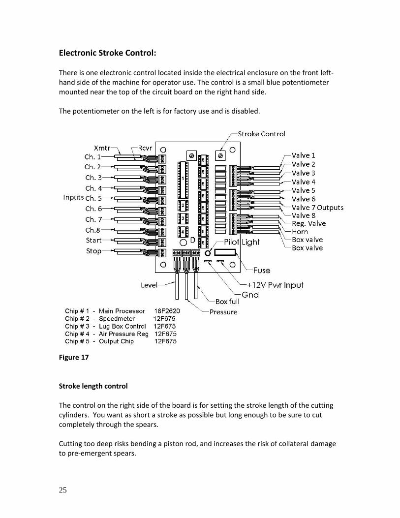
Electronic Stroke Control: There is one electronic control located inside the electrical enclosure on the front left-hand side of the machine for operator use. The control is a small blue potentiometer mounted near the top of the circuit board on the right hand side. The potentiometer on the left is for factory use and is disabled.
Figure 17 Stroke length control The control on the right side of the board is for setting the stroke length of the cutting cylinders. You want as short a stroke as possible but long enough to be sure to cut completely through the spears. Cutting too deep risks bending a piston rod, and increases the risk of collateral damage to pre-emergent spears.

26
Also located inside the electrical enclosure is a fuse. The wire coming from the tractors battery connects to the fuse. If the fuse blows there will be no power to the electronics on the harvester. The fuse is a 2 amp auto fuse. If the photo sensors and the pilot light on the circuit board don’t light up check the fuse.
27
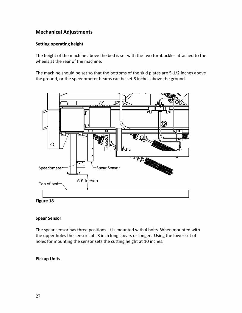
Mechanical Adjustments Setting operating height The height of the machine above the bed is set with the two turnbuckles attached to the wheels at the rear of the machine. The machine should be set so that the bottoms of the skid plates are 5-1/2 inches above the ground, or the speedometer beams can be set 8 inches above the ground.
Figure 18 Spear Sensor The spear sensor has three positions. It is mounted with 4 bolts. When mounted with the upper holes the sensor cuts 8 inch long spears or longer. Using the lower set of holes for mounting the sensor sets the cutting height at 10 inches. Pickup Units
28
The bottom pickup unit is mounted on a short swinging arm. The bottom pickup unit can be adjusted to fine tune the picking-up process for different machine speeds, length of spears etc. To rotate the pickup unit, loosen the two ¾” bolts on the ends of the aluminum bar. Box filling adjustments The spear discharge chute can be moved closer or further from the end of the conveyor as needed. Maintenance Refer to the air compressor manual for engine and compressor maintenance. The air compressor and diesel engine require daily, weekly, and monthly maintenance. The water should be drained daily from the air manifold, compressor tank, and the reservoir air tank. The rubber fingers on the bottom pickup unit near the bottom of the shafts will eventually wear out and will at some point need replacement fingers. When worn out they will begin dropping spears. The fingers in the last few inches of the 4 or 5 middle shafts will get the most wear. To replace rubber fingers, remove the push-nut from the end of the shaft, spray some soapy water on the fingers to be removed, and slide them off the shaft. (You will probably need to destroy the push-nut to get it off) With soapy water as a lubricant, slide on the new rubber fingers and put a new push-nut on the end of the shaft.
Alternatively you can leave the push nut alone and just force the fingers over the push-nuts. They will stretch enough to do that. The fingers could also be cut off.
29
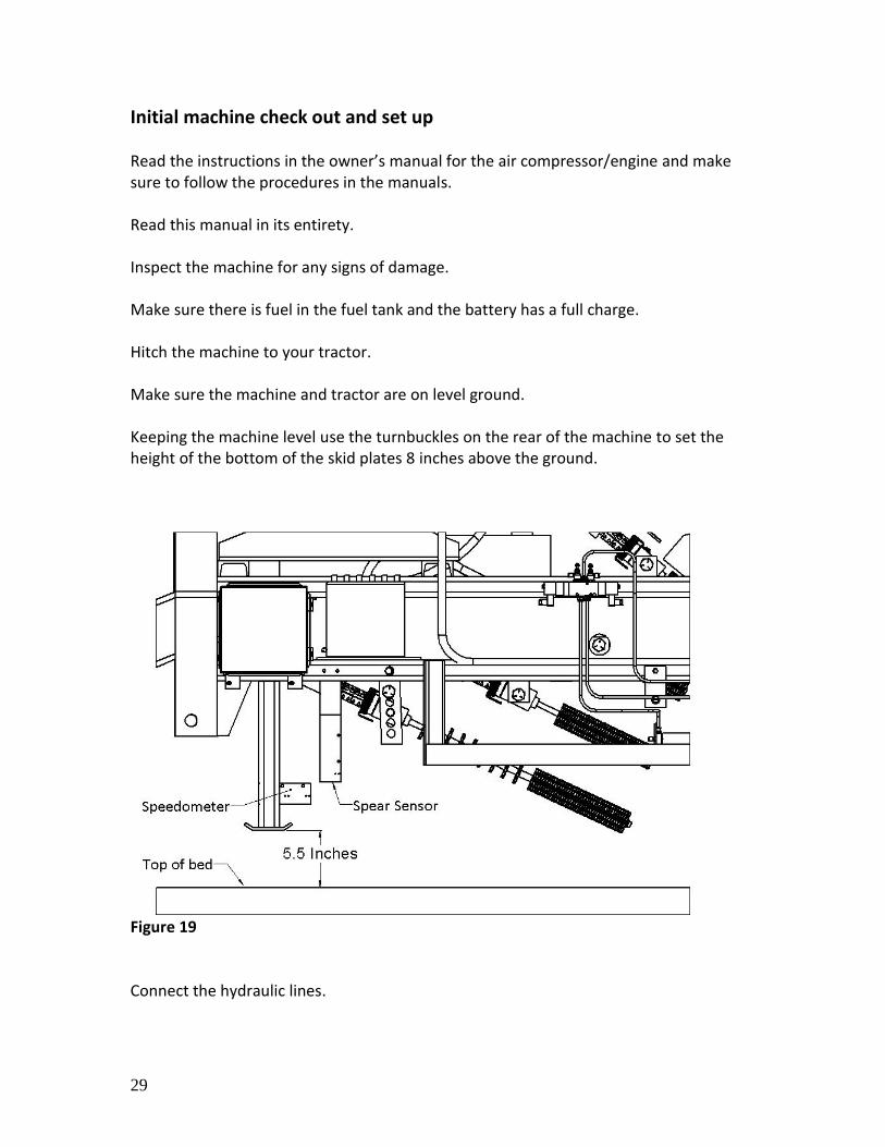
Initial machine check out and set up Read the instructions in the owner’s manual for the air compressor/engine and make sure to follow the procedures in the manuals. Read this manual in its entirety. Inspect the machine for any signs of damage. Make sure there is fuel in the fuel tank and the battery has a full charge. Hitch the machine to your tractor. Make sure the machine and tractor are on level ground. Keeping the machine level use the turnbuckles on the rear of the machine to set the height of the bottom of the skid plates 8 inches above the ground.
Figure 19 Connect the hydraulic lines.
30
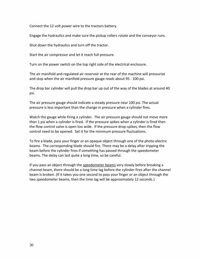
Connect the 12 volt power wire to the tractors battery. Engage the hydraulics and make sure the pickup rollers rotate and the conveyor runs. Shut down the hydraulics and turn off the tractor. Start the air compressor and let it reach full pressure. Turn on the power switch on the top right side of the electrical enclosure. The air manifold and regulated air reservoir at the rear of the machine will pressurize and stop when the air manifold pressure gauge reads about 95 - 100 psi. The drop bar cylinder will pull the drop bar up out of the way of the blades at around 40 psi. The air pressure gauge should indicate a steady pressure near 100 psi. The actual pressure is less important than the change in pressure when a cylinder fires. Watch the gauge while firing a cylinder. The air pressure gauge should not move more than 1 psi when a cylinder is fired. If the pressure spikes when a cylinder is fired then the flow control valve is open too wide. If the pressure drop-spikes, then the flow control need to be opened. Set it for the minimum pressure fluctuations. To fire a blade, pass your finger or an opaque object through one of the photo-electric beams. The corresponding blade should fire. There may be a delay after tripping the beam before the cylinder fires if something has passed through the speedometer beams. The delay can last quite a long time, so be careful. If you pass an object through the speedometer beams very slowly before breaking a channel beam, there should be a long time lag before the cylinder fires after the channel beam is broken. (If it takes you one second to pass your finger or an object through the two speedometer beams, then the time lag will be approximately 12 seconds.)
31
Harvesting We recommend beginning at a slower speed; about 1 mph should be a good starting point. It is much easier to see what’s happening when the machine is traveling slowly. When you are sure everything is working correctly, you can begin increasing the speed. As you increase your speed keep an eye out for an increase in dropped or missed spears. Also watch Look down a harvested row to see if there are missed spears, and if there are, are they lined up as though in one channel? If you see an increase in dropped spears as you increase your speed, you may need to increase the speed or fine-tune the position of the pickup rollers to get maximum yield. The machine should rarely miss a straight, non-leaning spear. However, if a spear leans too far in any direction it won’t get harvested. A few things to know… The harvester won’t establish proper timing until the second spear passes through the speedometer beams. That means the machine will miss the first spear it encounters after being switched on. If you suddenly have electronics problems try turning the power switch off and then back on again. This will reset the computer chips.
32
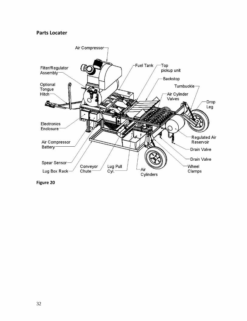
Parts Locater
Figure 20
33
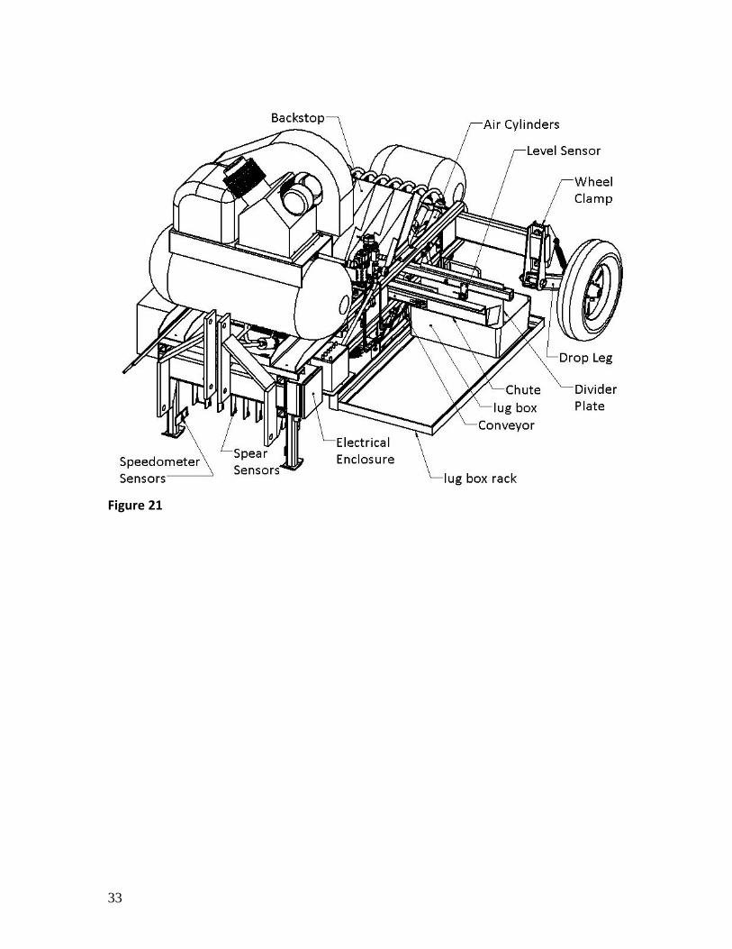
Figure 21
34
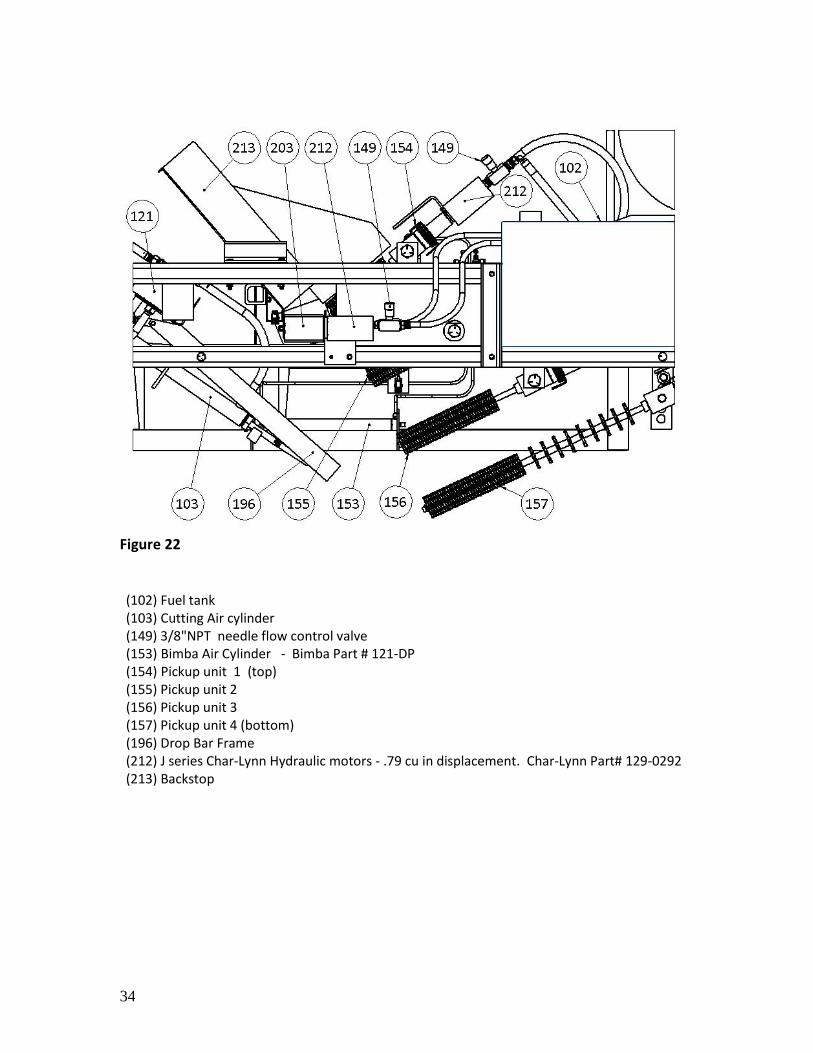
Figure 22
(102) Fuel tank (103) Cutting Air cylinder (149) 3/8"NPT needle flow control valve (153) Bimba Air Cylinder - Bimba Part # 121-DP (154) Pickup unit 1 (top) (155) Pickup unit 2 (156) Pickup unit 3 (157) Pickup unit 4 (bottom) (196) Drop Bar Frame (212) J series Char-Lynn Hydraulic motors - .79 cu in displacement. Char-Lynn Part# 129-0292 (213) Backstop
35
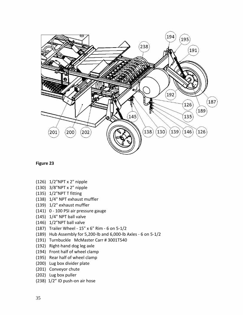
Figure 23
(126) 1/2"NPT x 2" nipple (130) 3/8"NPT x 2” nipple (135) 1/2"NPT T fitting (138) 1/4" NPT exhaust muffler (139) 1/2" exhaust muffler (141) 0 - 100 PSI air pressure gauge (145) 1/4" NPT ball valve (146) 1/2”NPT ball valve (187) Trailer Wheel - 15" x 6" Rim - 6 on 5-1/2 (189) Hub Assembly for 5,200-lb and 6,000-lb Axles - 6 on 5-1/2 (191) Turnbuckle McMaster Carr # 3001T540 (192) Right-hand dog leg axle (194) Front half of wheel clamp (195) Rear half of wheel clamp (200) Lug box divider plate (201) Conveyor chute (202) Lug box puller (238) 1/2” ID push-on air hose
36
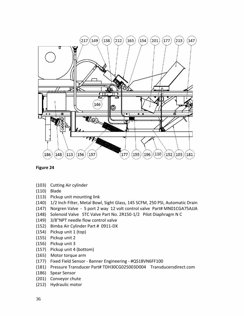
Figure 24 (103) Cutting Air cylinder (110) Blade (113) Pickup unit mounting link (140) 1/2 Inch Filter, Metal Bowl, Sight Glass, 145 SCFM, 250 PSI, Automatic Drain (147) Norgren Valve - 5 port 2 way 12 volt control valve Part# MN01CGA75AJJA (148) Solenoid Valve STC Valve Part No. 2R150-1/2 Pilot Diaphragm N C (149) 3/8"NPT needle flow control valve (152) Bimba Air Cylinder Part # 0911-DX (154) Pickup unit 1 (top) (155) Pickup unit 2 (156) Pickup unit 3 (157) Pickup unit 4 (bottom) (165) Motor torque arm (177) Fixed Field Sensor - Banner Engineering - #QS18VN6FF100 (181) Pressure Transducer Part# TDH30CG025003D004 Transducersdirect.com (186) Spear Sensor (201) Conveyor chute (212) Hydraulic motor

37
(213) Backstop (239) 1/2 “ID push-on air hose
38
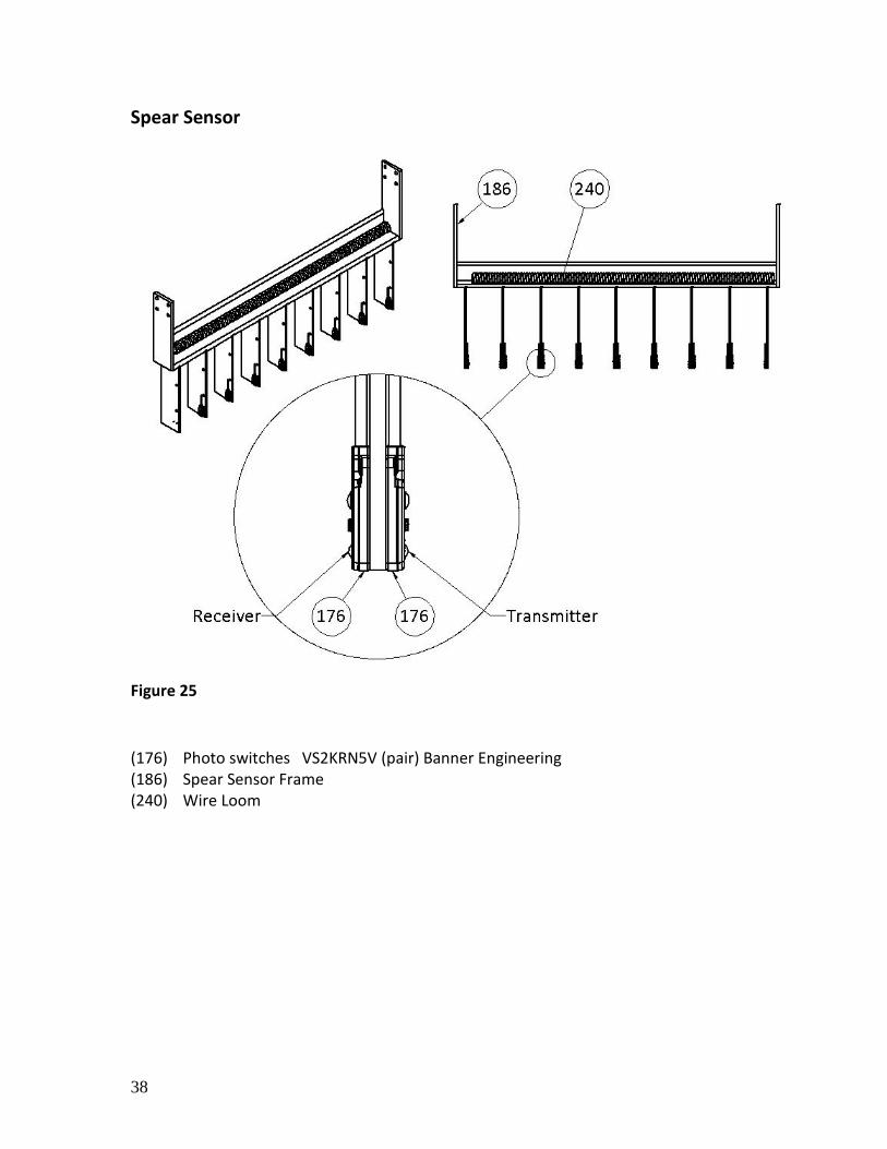
Spear Sensor
Figure 25
(176) Photo switches VS2KRN5V (pair) Banner Engineering (186) Spear Sensor Frame (240) Wire Loom
39
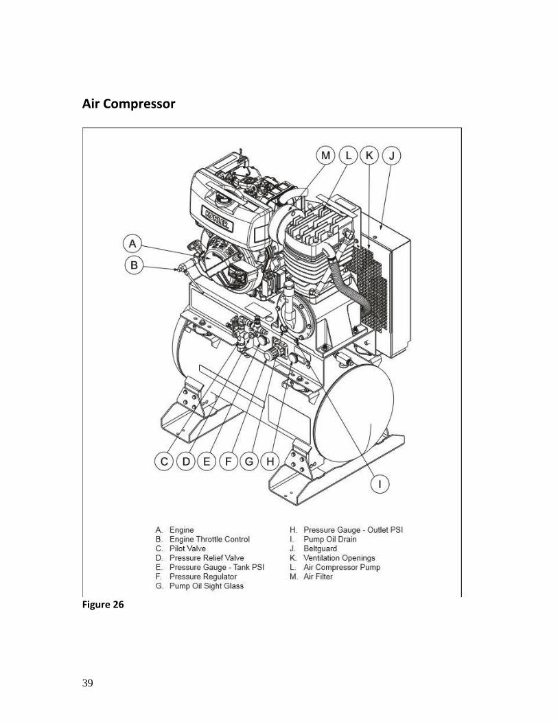
Air Compressor
Figure 26
40
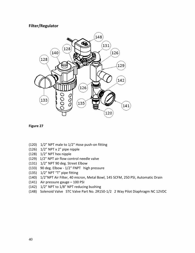
Filter/Regulator
Figure 27 (120) 1/2" NPT male to 1/2" Hose push-on fitting (126) 1/2" NPT x 2" pipe nipple (128) 1/2" NPT hex nipple (129) 1/2" NPT air flow control needle valve (131) 1/2" NPT 90 deg. Street Elbow (133) 90 deg. Elbow - 1/2" FNPT high pressure (135) 1/2" NPT “T” pipe fitting (140) 1/2"NPT Air Filter, 40 micron, Metal Bowl, 145 SCFM, 250 PSI, Automatic Drain (141) Air pressure gauge – 100 PSI (142) 1/2" NPT to 1/8" NPT reducing bushing (148) Solenoid Valve STC Valve Part No. 2R150-1/2 2 Way Pilot Diaphragm NC 12VDC
41
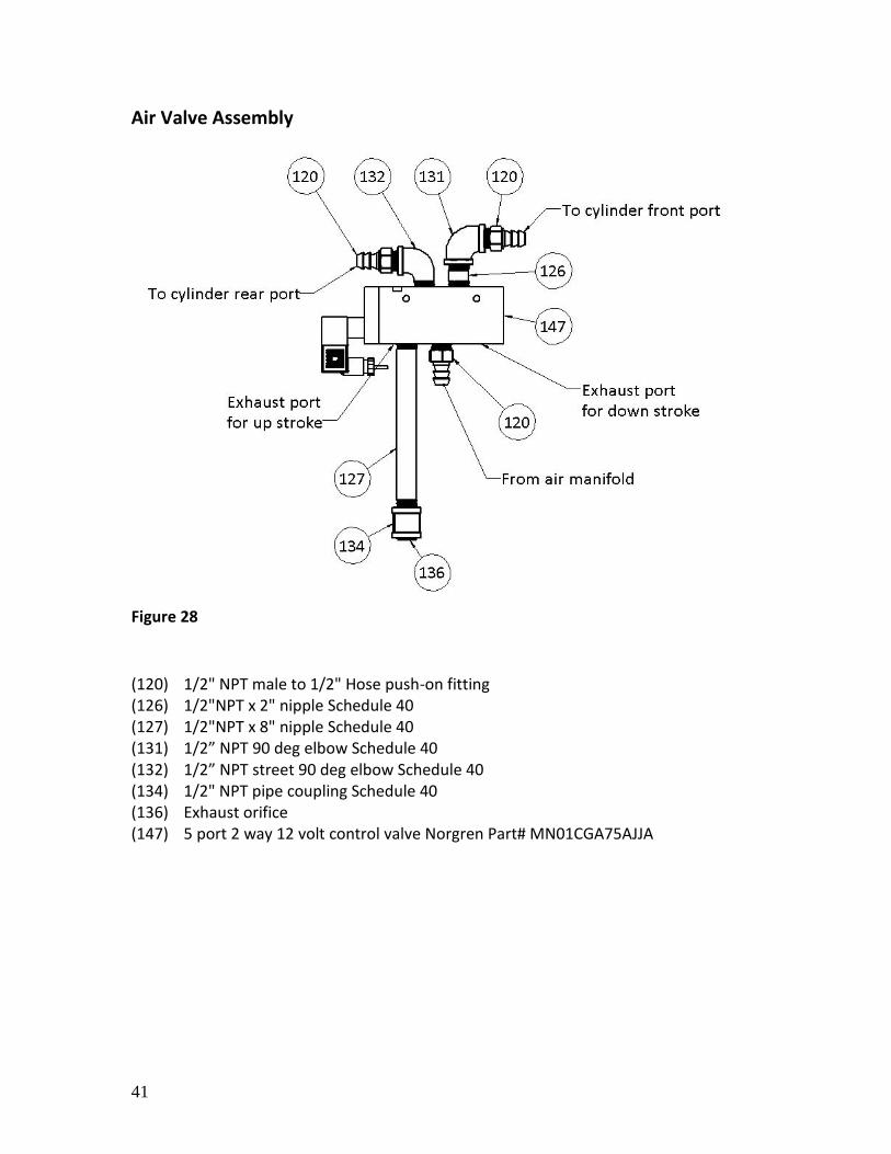
Air Valve Assembly
Figure 28
(120) 1/2" NPT male to 1/2" Hose push-on fitting (126) 1/2"NPT x 2" nipple Schedule 40 (127) 1/2"NPT x 8" nipple Schedule 40 (131) 1/2” NPT 90 deg elbow Schedule 40 (132) 1/2” NPT street 90 deg elbow Schedule 40 (134) 1/2" NPT pipe coupling Schedule 40 (136) Exhaust orifice (147) 5 port 2 way 12 volt control valve Norgren Part# MN01CGA75AJJA
42
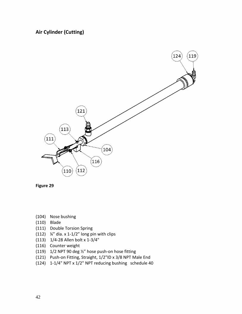
Air Cylinder (Cutting)
Figure 29
(104) Nose bushing (110) Blade (111) Double Torsion Spring (112) ¼” dia. x 1-1/2” long pin with clips (113) 1/4-28 Allen bolt x 1-3/4" (116) Counter weight (119) 1/2 NPT 90 deg ½” hose push-on hose fitting (121) Push-on Fitting, Straight, 1/2"ID x 3/8 NPT Male End (124) 1-1/4" NPT x 1/2" NPT reducing bushing schedule 40
43
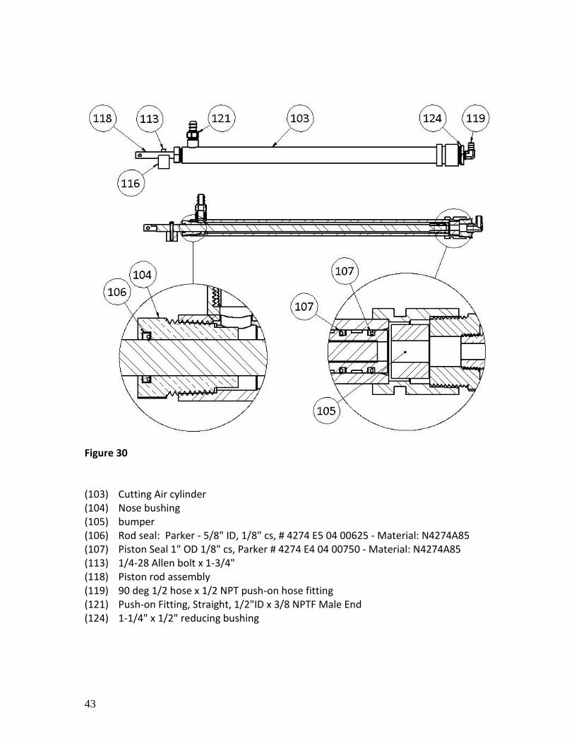
Figure 30 (103) Cutting Air cylinder (104) Nose bushing (105) bumper (106) Rod seal: Parker - 5/8" ID, 1/8" cs, # 4274 E5 04 00625 - Material: N4274A85 (107) Piston Seal 1" OD 1/8" cs, Parker # 4274 E4 04 00750 - Material: N4274A85 (113) 1/4-28 Allen bolt x 1-3/4" (118) Piston rod assembly (119) 90 deg 1/2 hose x 1/2 NPT push-on hose fitting (121) Push-on Fitting, Straight, 1/2"ID x 3/8 NPTF Male End (124) 1-1/4" x 1/2" reducing bushing
44
Blade Assembly
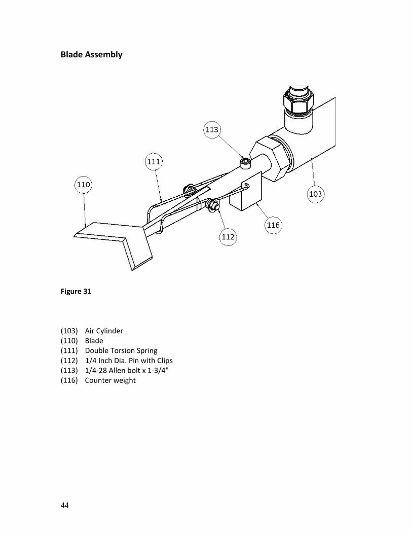
Figure 31 (103) Air Cylinder (110) Blade (111) Double Torsion Spring (112) 1/4 Inch Dia. Pin with Clips (113) 1/4-28 Allen bolt x 1-3/4" (116) Counter weight
45
Conveyor
Figure 32
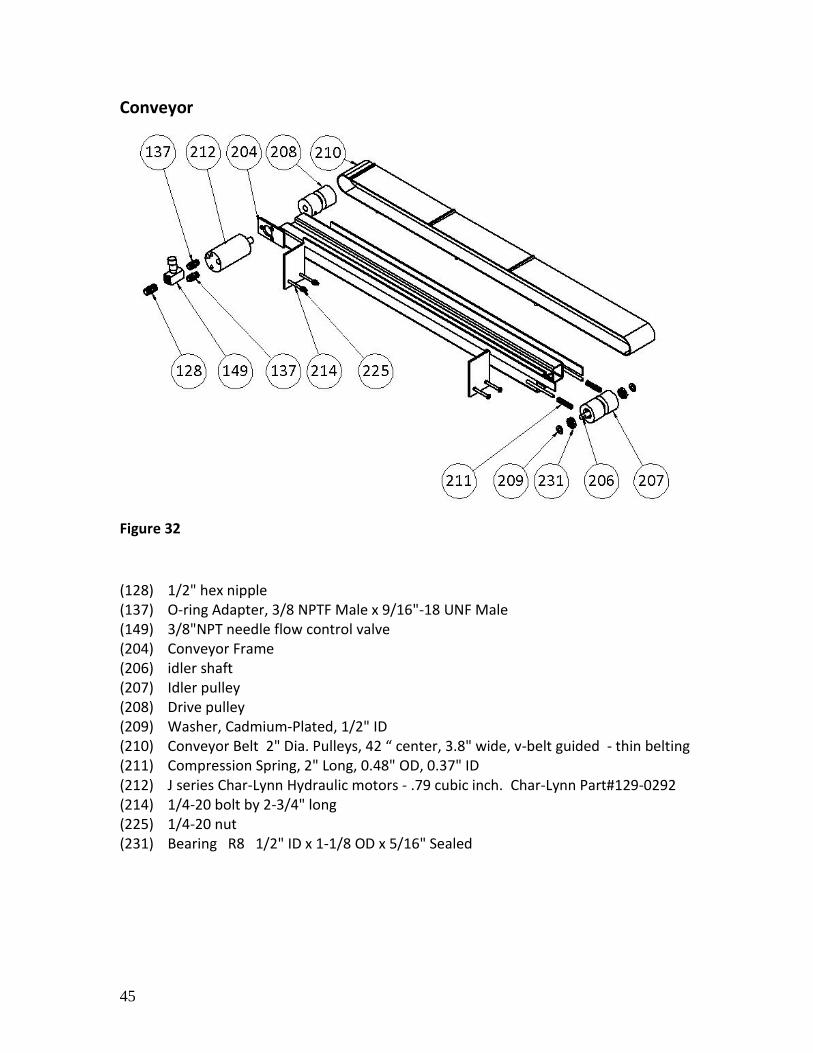
(128) 1/2" hex nipple (137) O-ring Adapter, 3/8 NPTF Male x 9/16"-18 UNF Male (149) 3/8"NPT needle flow control valve (204) Conveyor Frame (206) idler shaft (207) Idler pulley (208) Drive pulley (209) Washer, Cadmium-Plated, 1/2" ID (210) Conveyor Belt 2" Dia. Pulleys, 42 “ center, 3.8" wide, v-belt guided - thin belting (211) Compression Spring, 2" Long, 0.48" OD, 0.37" ID (212) J series Char-Lynn Hydraulic motors - .79 cubic inch. Char-Lynn Part#129-0292 (214) 1/4-20 bolt by 2-3/4" long (225) 1/4-20 nut (231) Bearing R8 1/2" ID x 1-1/8 OD x 5/16" Sealed
46
Pickup Unit
Figure 33
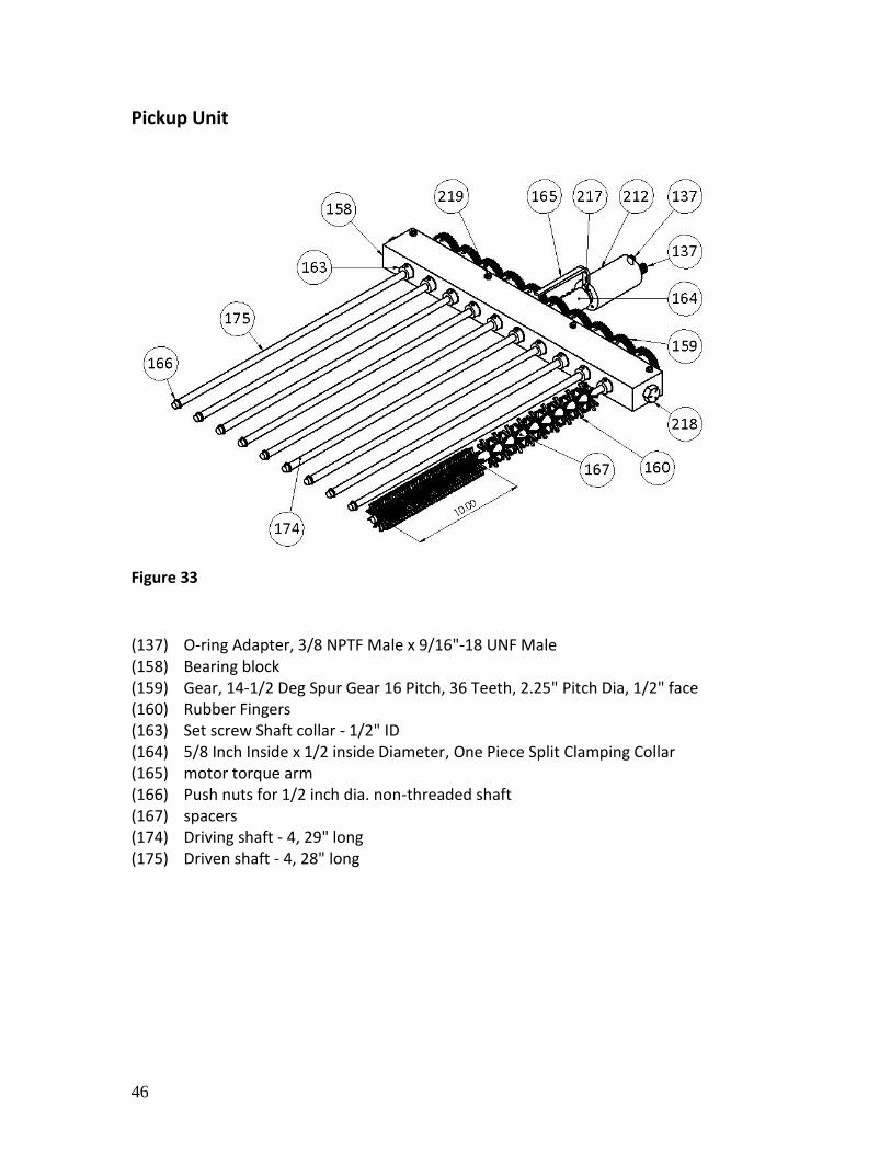
(137) O-ring Adapter, 3/8 NPTF Male x 9/16"-18 UNF Male (158) Bearing block (159) Gear, 14-1/2 Deg Spur Gear 16 Pitch, 36 Teeth, 2.25" Pitch Dia, 1/2" face (160) Rubber Fingers (163) Set screw Shaft collar - 1/2" ID (164) 5/8 Inch Inside x 1/2 inside Diameter, One Piece Split Clamping Collar (165) motor torque arm (166) Push nuts for 1/2 inch dia. non-threaded shaft (167) spacers (174) Driving shaft - 4, 29" long (175) Driven shaft - 4, 28" long
47
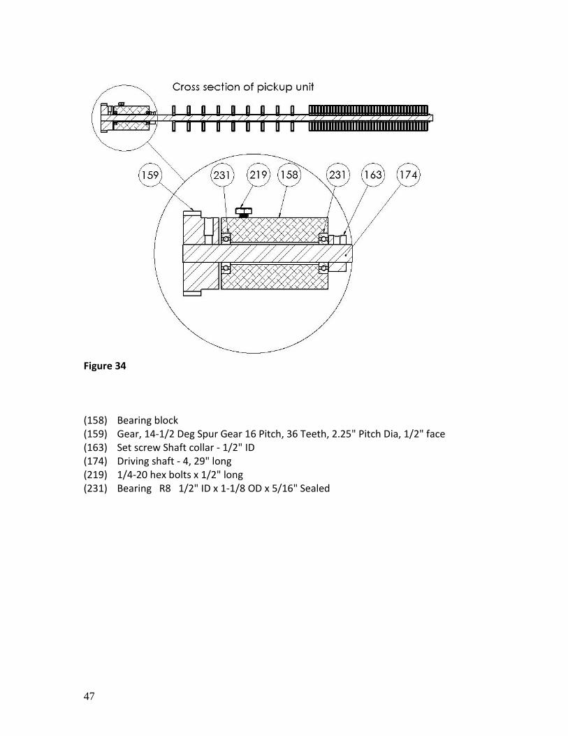
Figure 34 (158) Bearing block (159) Gear, 14-1/2 Deg Spur Gear 16 Pitch, 36 Teeth, 2.25" Pitch Dia, 1/2" face (163) Set screw Shaft collar - 1/2" ID (174) Driving shaft - 4, 29" long (219) 1/4-20 hex bolts x 1/2" long (231) Bearing R8 1/2" ID x 1-1/8 OD x 5/16" Sealed
48
Drop Bar Assembly
Figure 35
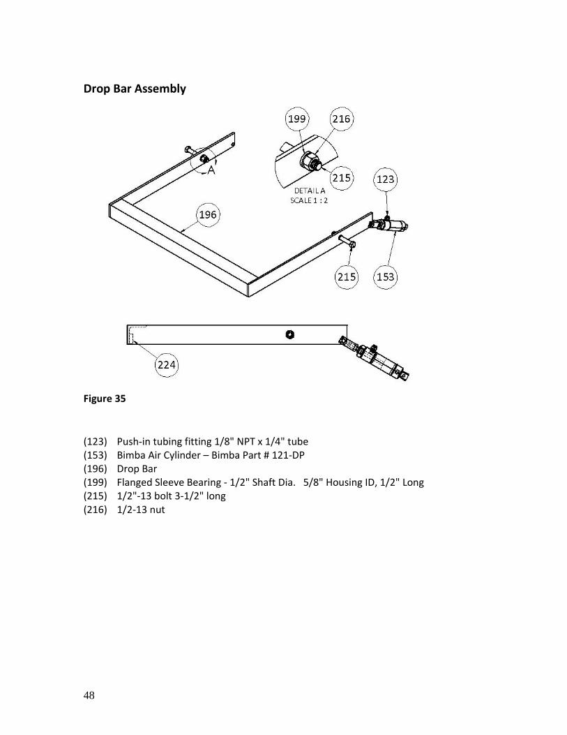
(123) Push-in tubing fitting 1/8" NPT x 1/4" tube (153) Bimba Air Cylinder – Bimba Part # 121-DP (196) Drop Bar (199) Flanged Sleeve Bearing - 1/2" Shaft Dia. 5/8" Housing ID, 1/2" Long (215) 1/2"-13 bolt 3-1/2" long (216) 1/2-13 nut
49
Fuel pump and filter location:
Figure 36
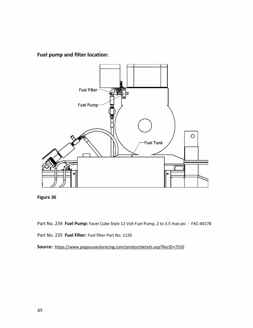
Part No. 234 Fuel Pump: Facet Cube Style 12 Volt Fuel Pump, 2 to 3.5 max psi - FAC-40178
Part No. 235 Fuel Filter: Fuel filter Part No. 1120
Source: https://www.pegasusautoracing.com/productdetails.asp?RecID=7550
50
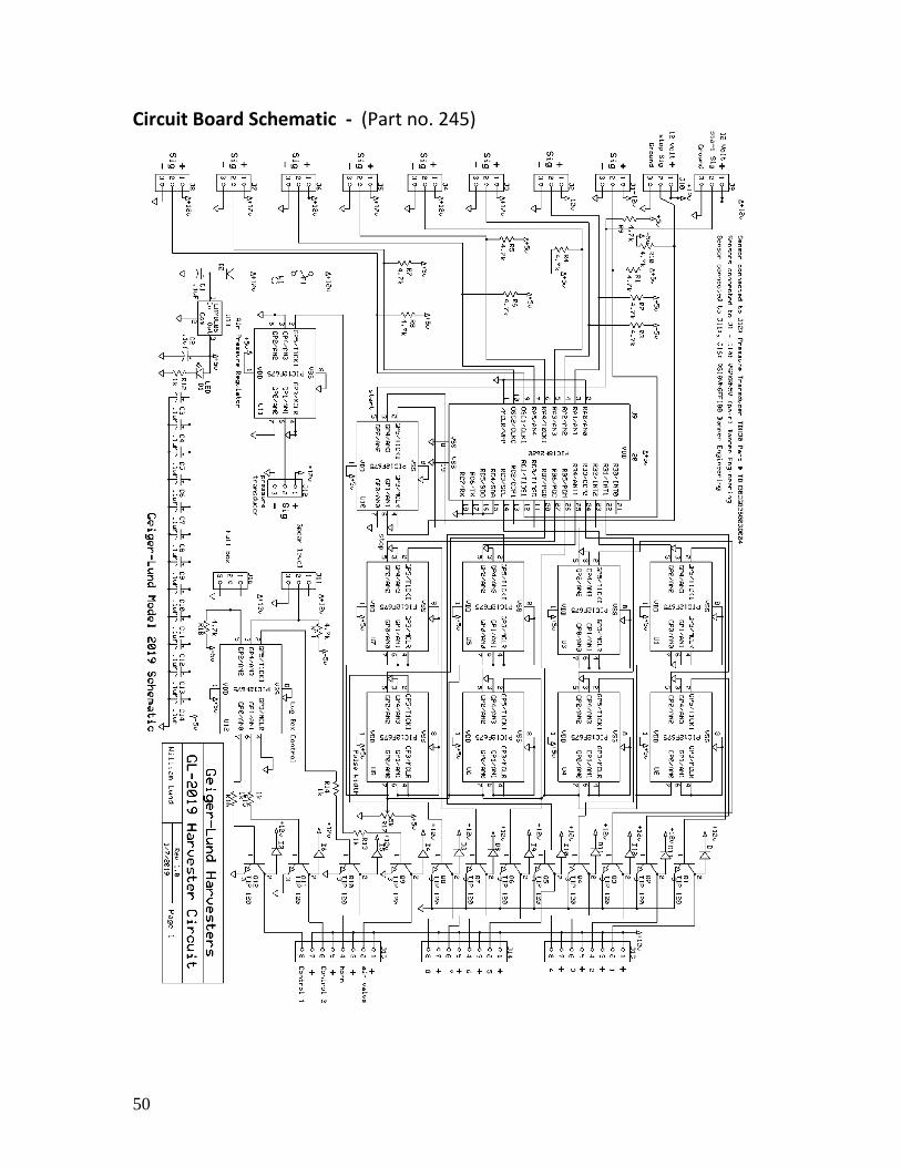
Circuit Board Schematic - (Part no. 245)

51
NOTES: