Embed Size (px)
Citation preview
innertec Systems Co.,LTD
GOLDENEYE INSTALL GUIDE MANUAL
GoldenEye Install Manual
GED200
Digital Video Recorder System
Winnertec Systems Co., Ltd
#405, 4FL, Ace Tech-no Tower 3, 197-48, Guro3-dong, Guro-gu,
Seoul, 152-766, Korea
TEL : +82-2-839-6531
FAX : +82-2-839-6573
Winnertec Systems Co.,LTD
2
GOLDENEYE INSTALL GUIDE MANUAL
4
5
5
5
6
7
7
7
8
8
8
9
9
10
10
10
11
11
13
14
16
17
17
19
19
20
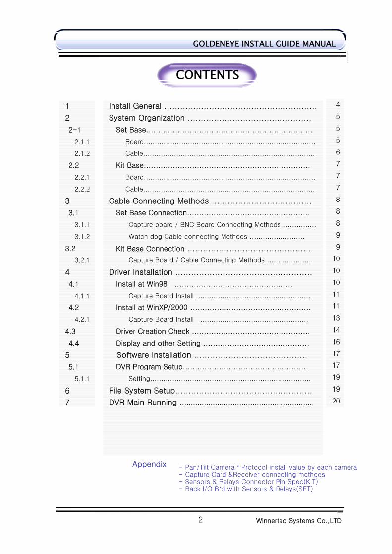
Install General ..……………………………………………….. System Organization ………………………………………..
Set Base…………………………………………………………… Board…………………………………………………………………… Cable……………………………………………………………………
Kit Base…………………………………………………………… Board…………………………………………………………………… Cable……………………………………………………………………
Cable Connecting Methods ……………………………….. Set Base Connection…………………………………………...
Capture board / BNC Board Connecting Methods …………… Watch dog Cable connecting Methods …….……………...
Kit Base Connection ……………………………………….. Capture Board / Cable Connecting Methods………………….
Driver Installation ………………………….………………… Install at Win98 ..……………………………….……….
Capture Board Install ……………….…………………………… Install at WinXP/2000 ….……………………………………….
Capture Board Install …………………………………………. Driver Creation Check ….………..……………………………. Display and other Setting ……….……………………………. Software Installation …………………………..……….. DVR Program Setup………………………………………….…
Setting……………………………………………….……………… File System Setup…………………………….……………… DVR Main Running …………………………………………………….
CONTENTS
1
2
2-1
2.1.1
2.1.2
2.2
2.2.1
2.2.2
3
3.1
3.1.1
3.1.2
3.2
3.2.1
4
4.1
4.1.1
4.2
4.2.1
4.3
4.4
5
5.1
5.1.1
6
7
- Pan/Tilt Camera ‘ Protocol install value by each camera- Capture Card &Receiver connecting methods - Sensors & Relays Connector Pin Spec(KIT) - Back I/O B’d with Sensors & Relays(SET)
Appendix
Winnertec Systems Co.,LTD
3
GOLDENEYE INSTALL GUIDE MANUAL
Thanks for choosing our products.
Please make sure to read this manual because this is explanation of system
program setting and Pan/Tilt control and the way of other equipment
1. Please power off before installation.
2. Please make an enough room to connect.
3. Please do not install this around magnetic material, all heating system.
(Adaptable temperature is 5℃~35℃)
4. Please install this to where be stable and flat.
5. Please do not put heavy thing on the monitor.
6. Please do not separate this intentionally. If you need to uncover this unit, please
contact the retailed seller and get help some tips.
. In case that you might break down this with using unrecorded components, we are
not responsible for any incident from this.
Products
Caution
Check the Components
Please check these items when you purchase it first and contact the shop where you
bought this in case you could not find as listed. (Option: Monitor, Audio Input Cable)
- In case of KIT
Related Cable(video, camera, sensor, other)
- In case of SET
1. Main DVR 2. Mouse 3. KeyBoard
4. Key 5. User Manual 6. Power Cable
7. CD (Software, other system CD)
Winnertec Systems Co.,LTD
4
GOLDENEYE INSTALL GUIDE MANUAL
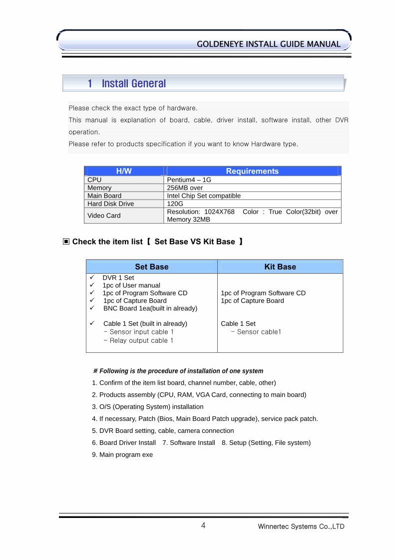
H/W Requirements CPU Pentium4 – 1G Memory 256MB over Main Board Intel Chip Set compatible Hard Disk Drive 120G
Video Card Resolution: 1024X768 Color : True Color(32bit) over Memory 32MB
▣ Check the item list【 Set Base VS Kit Base 】
Set Base Kit Base DVR 1 Set 1pc of User manual 1pc of Program Software CD 1pc of Capture Board BNC Board 1ea(built in already)
Cable 1 Set (built in already)
- Sensor input cable 1
- Relay output cable 1
1pc of Program Software CD 1pc of Capture Board Cable 1 Set
- Sensor cable1
Following is the procedure of installation of one system※
1. Confirm of the item list board, channel number, cable, other)
2. Products assembly (CPU, RAM, VGA Card, connecting to main board)
3. O/S (Operating System) installation
4. If necessary, Patch (Bios, Main Board Patch upgrade), service pack patch.
5. DVR Board setting, cable, camera connection
6. Board Driver Install 7. Software Install 8. Setup (Setting, File system)
9. Main program exe
Please check the exact type of hardware.
This manual is explanation of board, cable, driver install, software install, other DVR
operation.
Please refer to products specification if you want to know Hardware type.
1 Install General
Winnertec Systems Co.,LTD
5
GOLDENEYE INSTALL GUIDE MANUAL
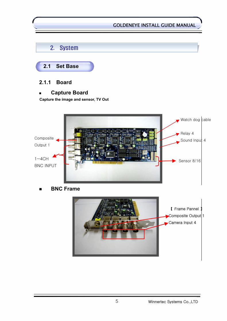
【 Frame Pannel 】
Composite Output 1
Camera Input 4
Capture Board
Capture the image and sensor, TV Out
BNC Frame
2. System
2.1 Set Base
2.1.1 Board
Watch dog cable
Relay 4
Sound Input 4
Sensor 8/16
Composite
Output 1
1~4CH
BNC INPUT
Winnertec Systems Co.,LTD
6
GOLDENEYE INSTALL GUIDE MANUAL
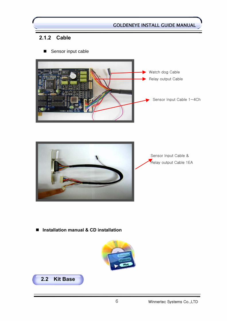
Watch dog Cable
Relay output Cable
Sensor Input Cable 1~4Ch
Sensor Input Cable &
Relay output Cable 1EA
2.1.2 Cable
Sensor input cable
Installation manual & CD installation
2.2 Kit Base
Winnertec Systems Co.,LTD
7
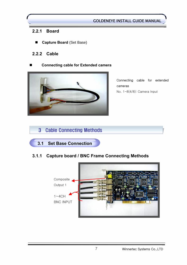
GOLDENEYE INSTALL GUIDE MANUAL
Connecting cable for extended
cameras
No. 1-8(4/8): Camera Input
2.2.1 Board
Capture Board (Set Base)
2.2.2 Cable Connecting cable for Extended camera
3.1.1 Capture board / BNC Frame Connecting Methods
3 Cable Connecting Methods
3.1 Set Base Connection
Composite
Output 1
1~4CH
BNC INPUT
Winnertec Systems Co.,LTD
8
GOLDENEYE INSTALL GUIDE MANUAL
【 Front Pannel 】
Composite Output 1
Camera Input 4
Relay / Sensor Input
Main Board
3.1.2 Watch dog Cable Connecting Methods Capture
4 Driver Installation
Reset Cable of case
should be connected here
To JP3 or JP4
Mother Board Reset pin should be connected
through relay output cable (J4)
Winnertec Systems Co.,LTD
9
GOLDENEYE INSTALL GUIDE MANUAL
After power on, automatically plug& play, Capture Board or Overlay B’d will be installed. Each B’d is composed of Audio / Video Capture Section
Driver install procedure ※ -Drivers capture
Overlay
4.1.1 Capture Board Install
4.1 Install at Win98
Location: In the driver folder provided CD driver in which capture
folder & overlay folder.
Select ‘specify a location’ & click ‘browse’
Winnertec Systems Co.,LTD
10
GOLDENEYE INSTALL GUIDE MANUAL
4.2.1 Capture Board Install
4.2 Install at WinXP/2000
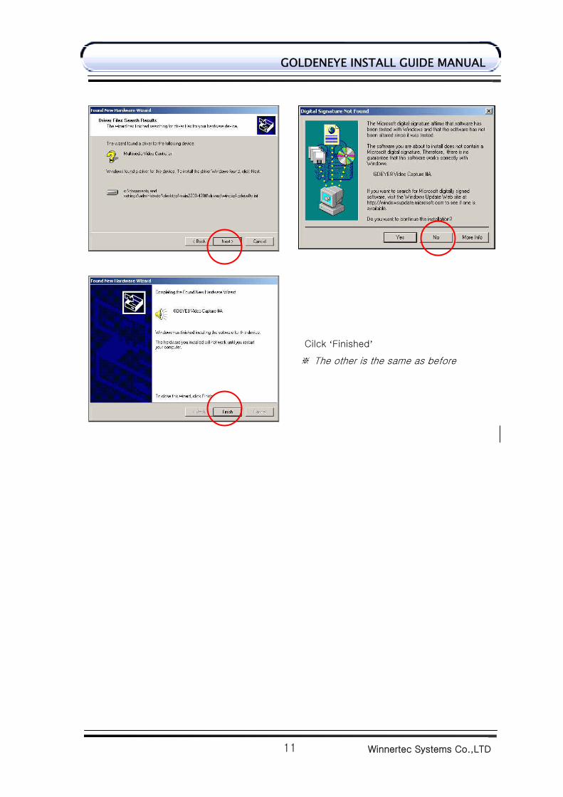
Click ‘finished’
※Automatic installation is going on after same
procedure.
Select ‘specify a location’ and click ‘browse’
Winnertec Systems Co.,LTD
11
GOLDENEYE INSTALL GUIDE MANUAL
Cilck ‘Finished’
※ The other is the same as before
Winnertec Systems Co.,LTD
12
GOLDENEYE INSTALL GUIDE MANUAL
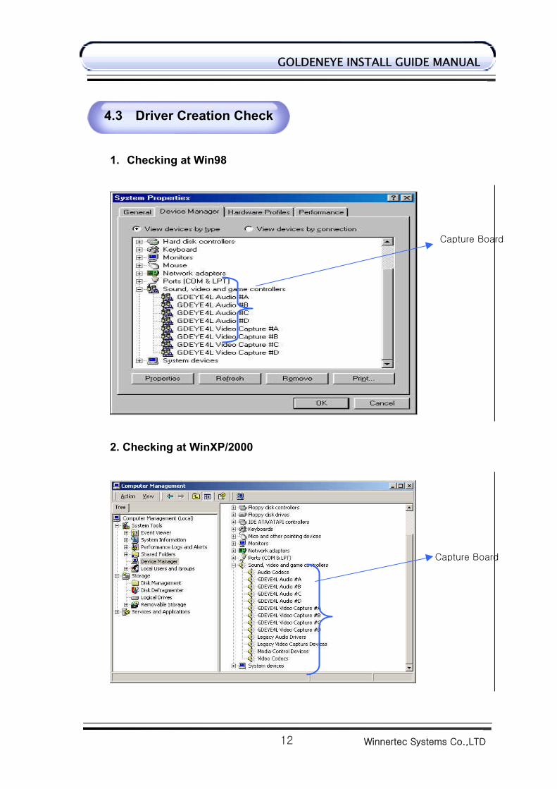
1. Checking at Win98
2. Checking at WinXP/2000
4.3 Driver Creation Check
Capture Board
Capture Board
Winnertec Systems Co.,LTD
13
GOLDENEYE INSTALL GUIDE MANUAL
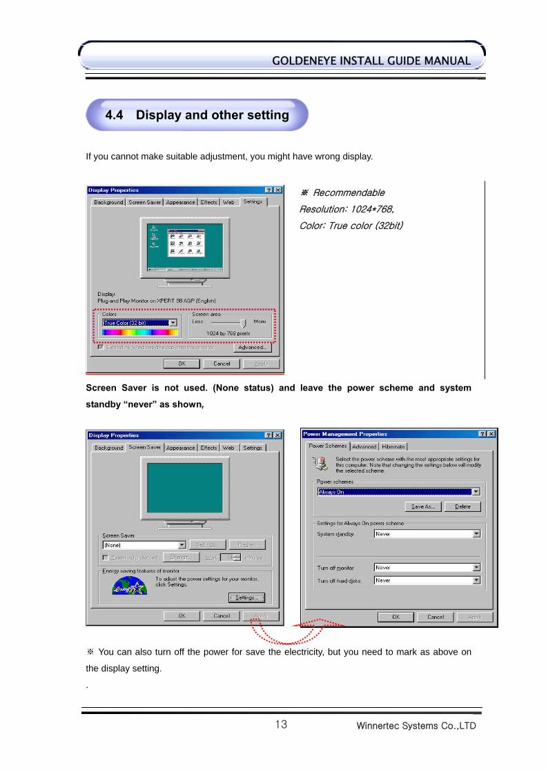
If you cannot make suitable adjustment, you might have wrong display.
Screen Saver is not used. (None status) and leave the power scheme and system
standby “never” as shown,
You can also turn off the power for save the electricity, but you need to mark as above on ※
the display setting.
.
4.4 Display and other setting
※ Recommendable
Resolution: 1024*768,
Color: True color (32bit)
Winnertec Systems Co.,LTD
14
GOLDENEYE INSTALL GUIDE MANUAL
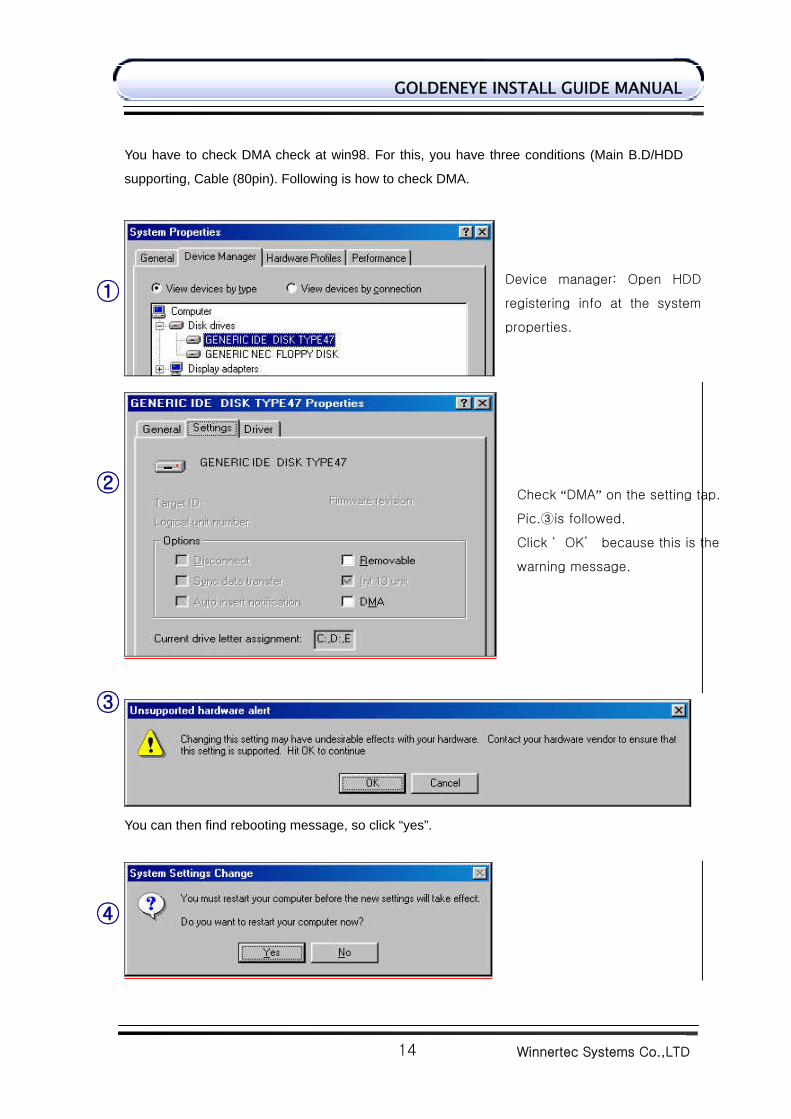
You have to check DMA check at win98. For this, you have three conditions (Main B.D/HDD
supporting, Cable (80pin). Following is how to check DMA.
You can then find rebooting message, so click “yes”.
④
Device manager: Open HDD
registering info at the system
properties.
①
②
③
Check “DMA” on the setting tap.
Pic.③is followed.
Click ‘ OK’ because this is the
warning message.
Winnertec Systems Co.,LTD
15
GOLDENEYE INSTALL GUIDE MANUAL
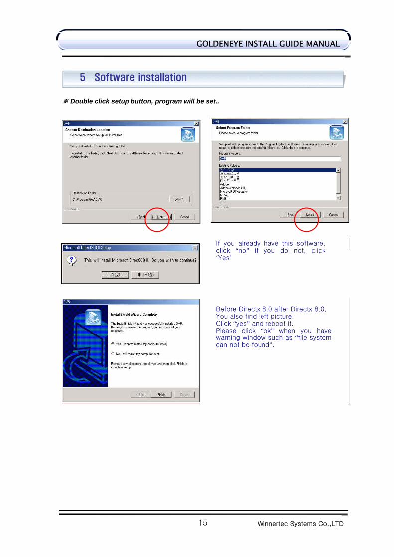
Double click setup button, program will be set.. ※
5 Software installation
If you already have this software,click “no” if you do not, click‘Yes’
Before Directx 8.0 after Directx 8.0,You also find left picture. Click “yes” and reboot it. Please click “ok” when you havewarning window such as “file systemcan not be found”.
Winnertec Systems Co.,LTD
16
GOLDENEYE INSTALL GUIDE MANUAL
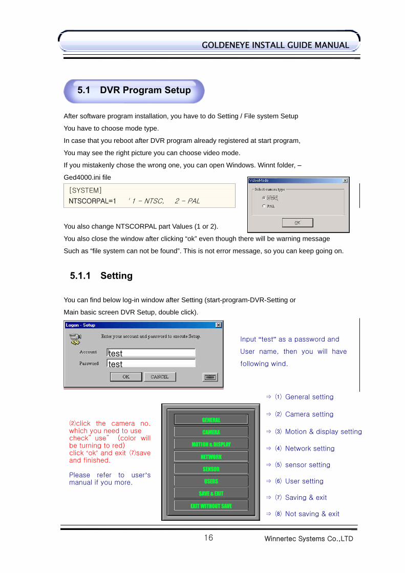
After software program installation, you have to do Setting / File system Setup
You have to choose mode type.
In case that you reboot after DVR program already registered at start program,
You may see the right picture you can choose video mode.
If you mistakenly chose the wrong one, you can open Windows. Winnt folder, –
Ged4000.ini file
You also change NTSCORPAL part Values (1 or 2).
You also close the window after clicking “ok” even though there will be warning message
Such as “file system can not be found”. This is not error message, so you can keep going on.
5.1.1 Setting You can find below log-in window after Setting (start-program-DVR-Setting or
Main basic screen DVR Setup, double click).
5.1 DVR Program Setup
Input “test” as a password and
User name, then you will have
following wind.
⇒ ⑴ General setting
⇒ ⑵ Camera setting
⇒ ⑶ Motion & display setting
⇒ ⑷ Network setting
⇒ ⑸ sensor setting
⇒ ⑹ User setting
⇒ ⑺ Saving & exit
⇒ ⑻ Not saving & exit
⑵click the camera no.which you need to use check” use” (color willbe turning to red) click ‘ok’ and exit ⑺saveand finished. Please refer to user’smanual if you more.
test
test
[SYSTEM]
NTSCORPAL=1 ' 1 - NTSC, 2 - PAL
Winnertec Systems Co.,LTD
17
GOLDENEYE INSTALL GUIDE MANUAL
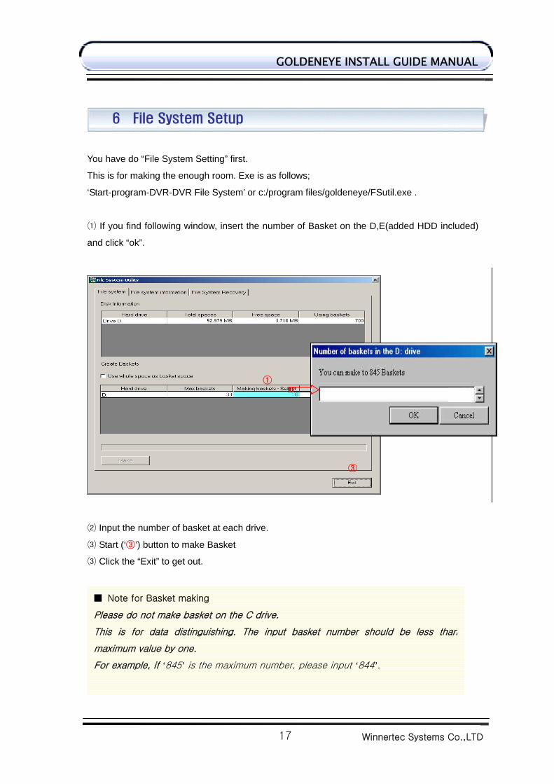
You have do “File System Setting” first.
This is for making the enough room. Exe is as follows;
‘Start-program-DVR-DVR File System’ or c:/program files/goldeneye/FSutil.exe .
If you find following window, insert the number of Basket on the D,E(added HDD included)⑴
and click “ok”.
⑵ Input the number of basket at each drive.
⑶ Start (‘③’) button to make Basket
⑶ Click the “Exit” to get out.
6 File System Setup
①
③
844
■ Note for Basket making
Please do not make basket on the C drive.
This is for data distinguishing. The input basket number should be less than
maximum value by one.
For example, if ‘845’ is the maximum number, please input ‘844’.
Winnertec Systems Co.,LTD
18
GOLDENEYE INSTALL GUIDE MANUAL
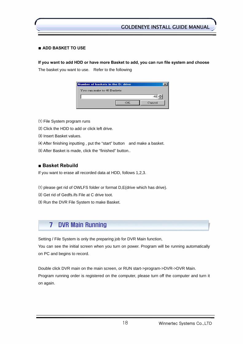
■ ADD BASKET TO USE
If you want to add HDD or have more Basket to add, you can run file system and choose
The basket you want to use. Refer to the following
⑴ File System program runs
⑵ Click the HDD to add or click left drive.
⑶ Insert Basket values.
⑷ After finishing inputting , put the “start” button and make a basket.
⑸ After Basket is made, click the “finished” button..
■ Basket Rebuild If you want to erase all recorded data at HDD, follows 1,2,3.
⑴ please get rid of OWLFS folder or format D,E(drive which has drive).
⑵ Get rid of Gedfs.ifs File at C drive toot.
⑶ Run the DVR File System to make Basket.
Setting / File System is only the preparing job for DVR Main function,
You can see the initial screen when you turn on power. Program will be running automatically
on PC and begins to record.
Double click DVR main on the main screen, or RUN start->program->DVR->DVR Main.
Program running order is registered on the computer, please turn off the computer and turn it
on again.
7 DVR Main Running
Winnertec Systems Co.,LTD
19
GOLDENEYE INSTALL GUIDE MANUAL
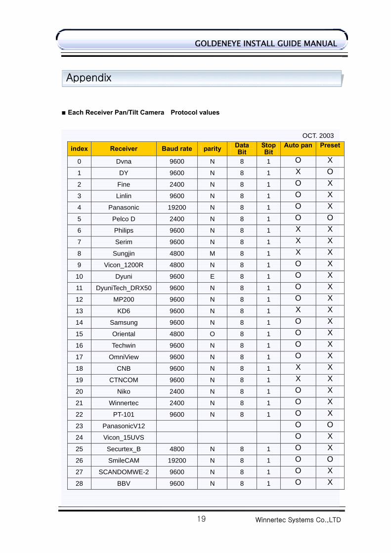
■ Each Receiver Pan/Tilt Camera Protocol values
OCT. 2003
index Receiver Baud rate parity Data Bit
Stop Bit
Auto pan Preset
0 Dvna 9600 N 8 1 O X
1 DY 9600 N 8 1 X O
2 Fine 2400 N 8 1 O X
3 Linlin 9600 N 8 1 O X
4 Panasonic 19200 N 8 1 O X
5 Pelco D 2400 N 8 1 O O
6 Philips 9600 N 8 1 X X
7 Serim 9600 N 8 1 X X
8 Sungjin 4800 M 8 1 X X
9 Vicon_1200R 4800 N 8 1 O X
10 Dyuni 9600 E 8 1 O X
11 DyuniTech_DRX50 9600 N 8 1 O X
12 MP200 9600 N 8 1 O X
13 KD6 9600 N 8 1 X X
14 Samsung 9600 N 8 1 O X
15 Oriental 4800 O 8 1 O X
16 Techwin 9600 N 8 1 O X
17 OmniView 9600 N 8 1 O X
18 CNB 9600 N 8 1 X X
19 CTNCOM 9600 N 8 1 X X
20 Niko 2400 N 8 1 O X
21 Winnertec 2400 N 8 1 O X
22 PT-101 9600 N 8 1 O X
23 PanasonicV12 O O
24 Vicon_15UVS O X
25 Securtex_B 4800 N 8 1 O X
26 SmileCAM 19200 N 8 1 O O
27 SCANDOMWE-2 9600 N 8 1 O X
28 BBV 9600 N 8 1 O X
Appendix
Winnertec Systems Co.,LTD
20
GOLDENEYE INSTALL GUIDE MANUAL
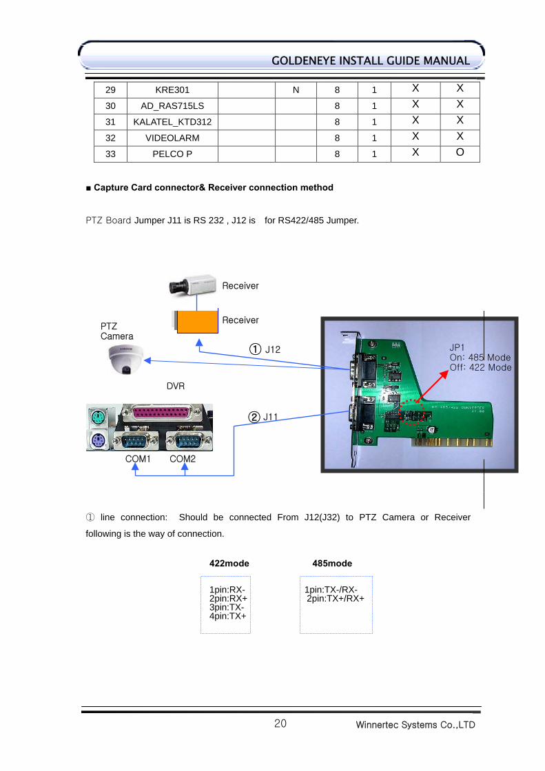
29 KRE301 N 8 1 X X
30 AD_RAS715LS 8 1 X X
31 KALATEL_KTD312 8 1 X X
32 VIDEOLARM 8 1 X X
33 PELCO P 8 1 X O
■ Capture Card connector& Receiver connection method
PTZ Board Jumper J11 is RS 232 , J12 is for RS422/485 Jumper.
① line connection: Should be connected From J12(J32) to PTZ Camera or Receiver
following is the way of connection.
422mode 485mode
1pin:RX- 1pin:TX-/RX- 2pin:RX+ 2pin:TX+/RX+ 3pin:TX- 4pin:TX+
Receiver
J12
PTZ Camera
①
Receiver
COM1 COM2
DVR
J11②
JP1On: 485 ModeOff: 422 Mode
Winnertec Systems Co.,LTD
21
GOLDENEYE INSTALL GUIDE MANUAL
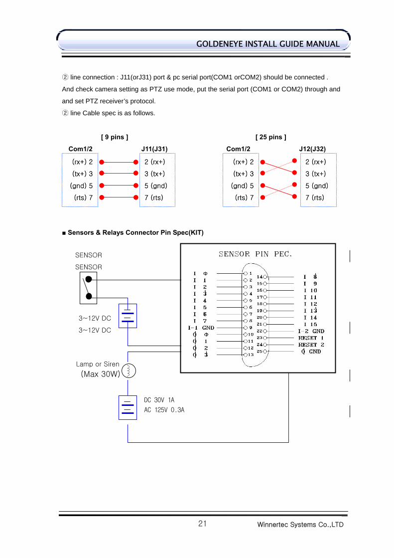
② line connection : J11(orJ31) port & pc serial port(COM1 orCOM2) should be connected .
And check camera setting as PTZ use mode, put the serial port (COM1 or COM2) through and
and set PTZ receiver’s protocol.
line Cable spec is as follows.②
[ 9 pins ] [ 25 pins ]
Com1/2 J11(J31) Com1/2 J12(J32)
■ Sensors & Relays Connector Pin Spec(KIT)
SENSOR
3~12V DC
(rx+) 2
(tx+) 3
(gnd) 5
(rts) 7
2 (rx+)
3 (tx+)
5 (gnd)
7 (rts)
(rx+) 2
(tx+) 3
(gnd) 5
(rts) 7
2 (rx+)
3 (tx+)
5 (gnd)
7 (rts)
(rx+) 2
(tx+) 3
(gnd) 5
(rts) 7
2 (rx+)
3 (tx+)
5 (gnd)
7 (rts)
(rx+) 2
(tx+) 3
(gnd) 5
(rts) 7
2 (rx+)
3 (tx+)
5 (gnd)
7 (rts)
SENSOR
3~12V DC
Lamp or Siren
(Max 30W)
DC 30V 1A
AC 125V 0.3A
Winnertec Systems Co.,LTD
22
GOLDENEYE INSTALL GUIDE MANUAL
We here by certify that we can reverse this DVR when you are using this properly
tested product.
1. Please contact the sales contact point after Double-checking
2. Repairing, reimbursement, exchanges are made according to Customer damage
reimbursement regulation.
We can repair our products under the normal circumstance within one year.
(But, Except Act of God, National emergency)
Following cases are that we have to ask some charge.
1. Breaking down from Careless handing.
2. Non-obedience of the manual indicated.
3. Non-use of fixed power we had suggested.
4. When you need additional components or you want it cleared
We cannot guarantee the entire request after A/S term.
Some amount of cost will be added if the customer wants to repair.
Model
Serial no
Purchasing place/Tel
Date of purchase
Warrantee period
NAME
ADDRESS CUSTOMER
TEL
This warranty sheet is not reissued.⊙
Please feel the blank when you purchase this.⊙
Please show us when you ask free repairing.⊙
Warranty Introduction
Warranty Contents