Embed Size (px)
Citation preview

ES0008 Rev. I Copyright © GED 2010 Page 1 of 15
GED Integrated Solutions, Inc. 31100 Diamond Parkway Glenwillow, OH 44139
Document No: ES-0008
Revision Level: I
DATE: 08/18/10
Subject: Intercept® Spacer Frame Finished Quality Specifications Written By: Ken Collier Approved By: Bill Briese
Revision History: Release No.: Changed By: Date:
I Update splay & bow specification 04365 Bill Briese 08/18/10
H Removed tolerances on Punch Detail #3 on page 4 & 5; added swage crease, corner folding ULTRA data & crimping information on pages 7, 8 & 11 04293
Roger Eberwein
05/13/09
G Edit formatting Ken Collier 02/01/08
F Added detailed pictures on pg. 7 showing 03626 corner measuring techniques.
Tim Hall 06/03/05
E Correct tolerances for corner flare & 03111 protrusion, re-format text, update GED’s address.
Ken Collier 01/17/03
D Reorganized , made corrections 02628 Ken Collier 07/19/00 C Revised Side and Upward/Downward 01622
Bow measuring methods TBM 06/30/97
B Revised Bow, twist and Finish section; 01469 Min. corner gap was .030”
MJG 03/03/97
A Original Release -------- MJG ----------
Intercept™ Spacer Frame Finished Quality Specifications
GED Integrated Solutions, Inc.
ES0008 Rev. I Copyright © GED 2010 Page 2 of 15
Table of Contents
INTERCEPT™ SPACER FRAME FINISHED QUALITY SPECIFICATIONS 1
Table of Contents 2
Punches & Punch Depths 3 Intercept Reference Drawings - Punched Strip, Strip Width and Spacer 4 Standard Profile (Ref. GED Drawing # 1-12121) 5 Low Profile (Ref. GED Drawing # 1-12125) 6
Finished Spacer Dimensions 7 Overall Dimensions 7 Formed Spacer Width 8 Splay 8 Assembled Spacer Size (in box form) 8 Tab Swage 9 Cut-off Location 9 Corners 10 Corner Flare 10 Measuring 10 Over Bending 11 Corner twist 11 Corner Protrusions 11 Corner gap 11 Back Bending 12 Web Impression/Punch Pressure 12 Bow, Twist, and Finish 13 Making the Test Spacers 13 Checking for Side Bow 14 Checking for Upward/Downward Bow 14 Checking for Twist and Finish 15
Additional References: 15 Intercept® Raw Material Specifications - GED Document # ED 0019 15 Quality Now - PPG IG Quality Assurance Manual 15
ES0008 Rev. I Copyright © GED 2010 Page 3 of 15
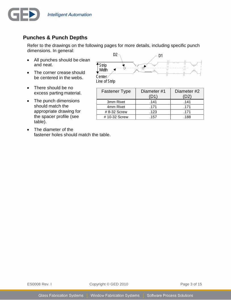
Punches & Punch Depths
Refer to the drawings on the following pages for more details, including specific punch dimensions. In general:
D2 D1 • All punches should be clean
and neat.
• The corner crease should be centered in the webs.
• There should be no
excess parting material.
• The punch dimensions should match the appropriate drawing for the spacer profile (see table).
• The diameter of the
Strip Width
Center Line of Strip
Fastener Type Diameter #1
(D1) Diameter #2
(D2) 3mm Rivet .141 .141 4mm Rivet .171 .171
# 8-32 Screw .123 .171 # 10-32 Screw .157 .188
fastener holes should match the table.
ES0008 Rev. I Copyright © GED 2010 Page 4 of 15
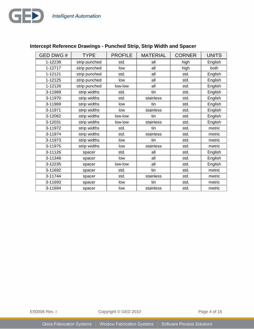
Intercept Reference Drawings - Punched Strip, Strip Width and Spacer
GED DWG # TYPE PROFILE MATERIAL CORNER UNITS 1-12238 strip punched std. all high English 1-12717 strip punched low all high both 1-12121 strip punched std. all std. English 1-12125 strip punched low all std. English 1-12126 strip punched low-low all std. English 3-11968 strip widths std. tin std. English 3-11970 strip widths std. stainless std. English 3-11969 strip widths low tin std. English 3-11971 strip widths low stainless std. English 3-12062 strip widths low-low tin std. English 3-12031 strip widths low-low stainless std. English 3-11972 strip widths std. tin std. metric 3-11974 strip widths std. stainless std. metric 3-11973 strip widths low tin std. metric 3-11975 strip widths low stainless std. metric 3-11126 spacer std. all std. English 3-11349 spacer low all std. English 3-12235 spacer low-low all std. English 3-11692 spacer std. tin std. metric 3-11744 spacer std. stainless std. metric 3-11693 spacer low tin std. metric 3-11694 spacer low stainless std. metric
ES0008 Rev. I Copyright © GED 2010 Page 5 of 15
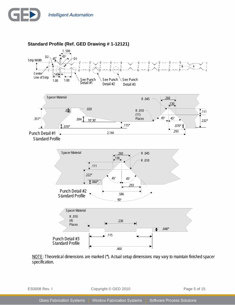
Spacer Material
R .010 (4) Places
.230
.048*
Punch Detail #3 Standard Profile
.115
Standard Profile (Ref. GED Drawing # 1-12121) 1. 500
D2 Strip Width 45° 45° D1
Center Line of Strip
.145
1.00
1.00 See Punch Detail #1
See Punch Detail #2
See Punch Detail #3
.351*
Spacer Material
.076
.020
.094 10°30’
R .045
R .010 (11) Places
.260 .130
45° 45°
.111
.232*
Punch Detail #1 .070* .115*
2.144
.070* .293
Standard Profile
.460
NOTE: Theoretical dimensions are marked (*). Actual setup dimensions may vary to maintain finished spacer specification.
Spacer Material .260 .130
R .045
R .010 .111
.222*
45° 45° .060*
.293
Punch Detail #2 Standard Profile .586
90°
ES0008 Rev. I Copyright © GED 2010 Page 6 of 15
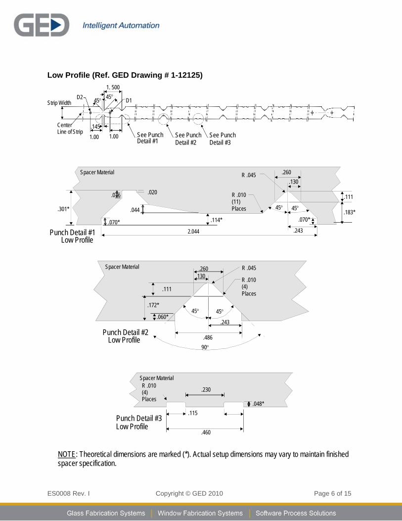
Spacer Material R .010 (4) Places
.230
.048* Punch Detail #3 Low Profile
.115
Low Profile (Ref. GED Drawing # 1-12125) 1. 500
D2 Strip Width 45° 45° D1
Center Line of Strip
.145
1.00
1.00 See Punch Detail #1
See Punch Detail #2
See Punch Detail #3
.301*
Spacer Material
.076
.020
.044
R .045
R .010 (11) Places
.260
.130
45° 45°
.111
.183*
Punch Detail #1 Low Profile
.070* .114* 2.044
.070*
.243
.460
NOTE: Theoretical dimensions are marked (*). Actual setup dimensions may vary to maintain finished spacer specification.
Spacer Material .260 .130
.172*
.111
R .045
R .010 (4) Places
.060*
45° 45°
.243
Punch Detail #2 Low Profile .486
90°
ES0008 Rev. I Copyright © GED 2010 Page 7 of 15
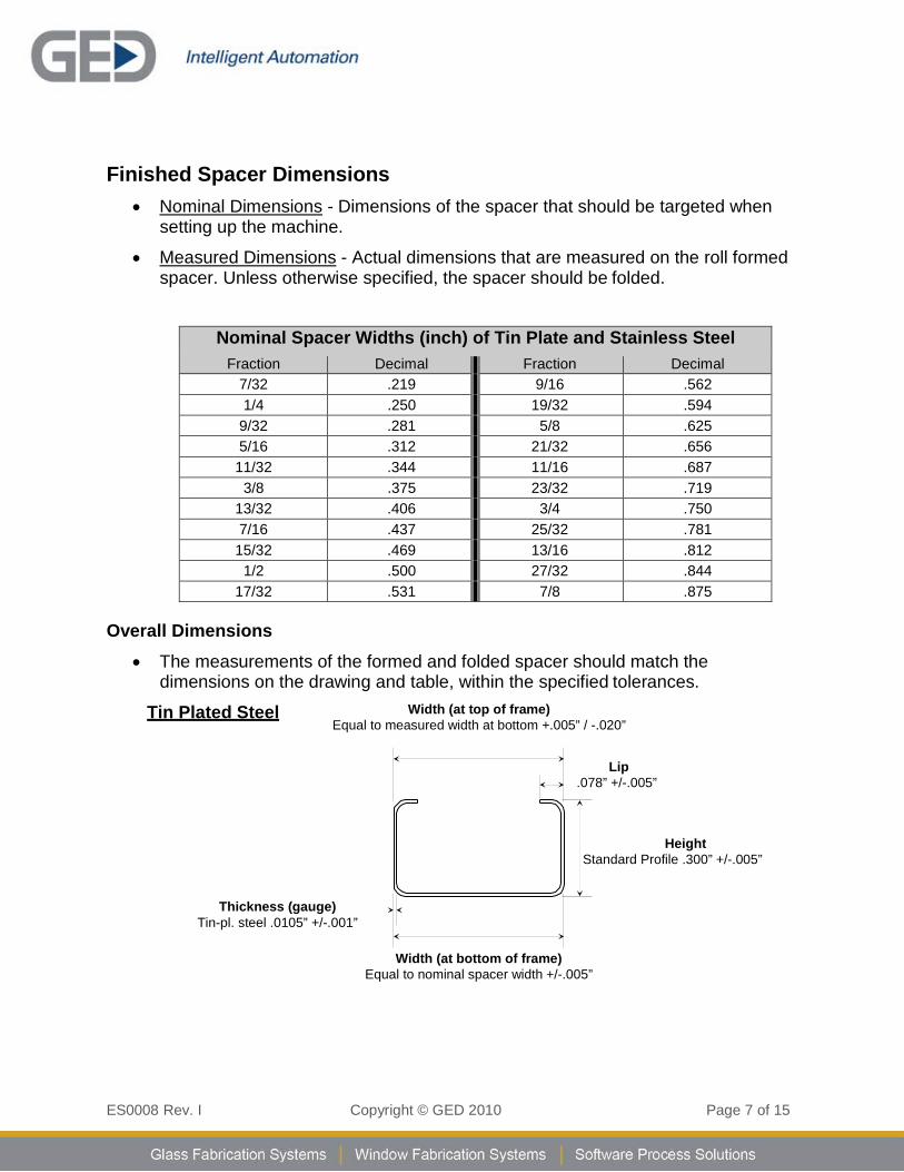
Finished Spacer Dimensions • Nominal Dimensions - Dimensions of the spacer that should be targeted when
setting up the machine.
• Measured Dimensions - Actual dimensions that are measured on the roll formed spacer. Unless otherwise specified, the spacer should be folded.
Nominal Spacer Widths (inch) of Tin Plate and Stainless Steel Fraction Decimal Fraction Decimal
7/32 .219 9/16 .562 1/4 .250 19/32 .594
9/32 .281 5/8 .625 5/16 .312 21/32 .656 11/32 .344 11/16 .687
3/8 .375 23/32 .719 13/32 .406 3/4 .750 7/16 .437 25/32 .781 15/32 .469 13/16 .812
1/2 .500 27/32 .844 17/32 .531 7/8 .875
Overall Dimensions • The measurements of the formed and folded spacer should match the
dimensions on the drawing and table, within the specified tolerances.
Tin Plated Steel Width (at top of frame) Equal to measured width at bottom +.005” / -.020”
Lip
.078” +/-.005”
Height Standard Profile .300” +/-.005”
Thickness (gauge)
Tin-pl. steel .0105” +/-.001”
Width (at bottom of frame) Equal to nominal spacer width +/-.005”
ES0008 Rev. I Copyright © GED 2010 Page 8 of 15
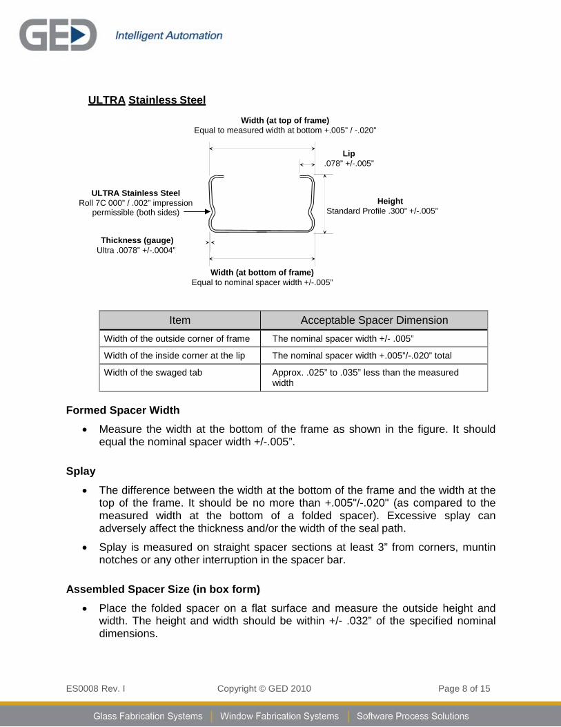
ULTRA Stainless Steel
Width (at top of frame)
Equal to measured width at bottom +.005” / -.020”
Lip .078” +/-.005”
ULTRA Stainless Steel Roll 7C 000” / .002” impression
permissible (both sides)
Height Standard Profile .300” +/-.005”
Thickness (gauge)
Ultra .0078” +/-.0004”
Width (at bottom of frame) Equal to nominal spacer width +/-.005”
Item Acceptable Spacer Dimension Width of the outside corner of frame The nominal spacer width +/- .005”
Width of the inside corner at the lip The nominal spacer width +.005”/-.020” total
Width of the swaged tab Approx. .025” to .035” less than the measured width
Formed Spacer Width • Measure the width at the bottom of the frame as shown in the figure. It should
equal the nominal spacer width +/-.005”.
Splay • The difference between the width at the bottom of the frame and the width at the
top of the frame. It should be no more than +.005"/-.020" (as compared to the measured width at the bottom of a folded spacer). Excessive splay can adversely affect the thickness and/or the width of the seal path.
• Splay is measured on straight spacer sections at least 3” from corners, muntin notches or any other interruption in the spacer bar.
Assembled Spacer Size (in box form)
• Place the folded spacer on a flat surface and measure the outside height and width. The height and width should be within +/- .032” of the specified nominal dimensions.
ES0008 Rev. I Copyright © GED 2010 Page 9 of 15
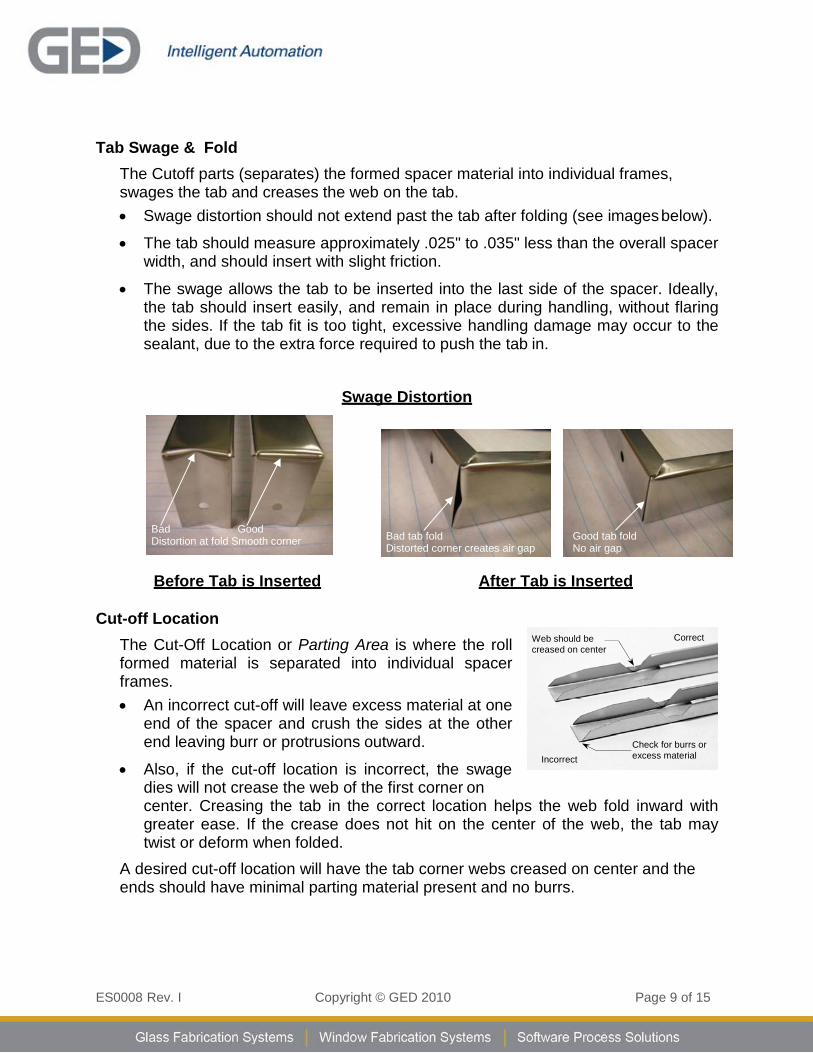
Tab Swage & Fold The Cutoff parts (separates) the formed spacer material into individual frames, swages the tab and creases the web on the tab. • Swage distortion should not extend past the tab after folding (see images below).
• The tab should measure approximately .025" to .035" less than the overall spacer width, and should insert with slight friction.
• The swage allows the tab to be inserted into the last side of the spacer. Ideally, the tab should insert easily, and remain in place during handling, without flaring the sides. If the tab fit is too tight, excessive handling damage may occur to the sealant, due to the extra force required to push the tab in.
Swage Distortion
Before Tab is Inserted After Tab is Inserted
Cut-off Location The Cut-Off Location or Parting Area is where the roll formed material is separated into individual spacer frames. • An incorrect cut-off will leave excess material at one
end of the spacer and crush the sides at the other end leaving burr or protrusions outward.
• Also, if the cut-off location is incorrect, the swage dies will not crease the web of the first corner on center. Creasing the tab in the correct location helps the web fold inward with greater ease. If the crease does not hit on the center of the web, the tab may twist or deform when folded.
A desired cut-off location will have the tab corner webs creased on center and the ends should have minimal parting material present and no burrs.
Bad Good Distortion at fold Smooth corner
Bad tab fold Distorted corner creates air gap
Good tab fold No air gap
Web should be creased on center
Correct
Incorrect Check for burrs or excess material
ES0008 Rev. I Copyright © GED 2010 Page 10 of 15
Corners Protrusions on bearing surfaces should not exceed +.005”. Such protrusions may be a result of over-bending or twisting the corners, insufficient punch depth from the edge of the material or flaring due to roll forming. Such deformities may adversely affect the sealant thickness. If a minimum seal thickness is not achieved, premature seal failure is likely. Typically the sealant thickness between the glass and spacer in a finished IG unit is a minimum of .015” to a maximum of .025” in all areas.
Corner Flare (Maximum +.005” per side)
Corner Flare may be the result of over bending a corner, twisting the corner or improper machine set-up (maintenance function).
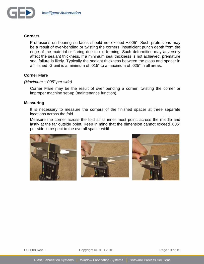
Measuring
It is necessary to measure the corners of the finished spacer at three separate locations across the fold. Measure the corner across the fold at its inner most point, across the middle and lastly at the far outside point. Keep in mind that the dimension cannot exceed .005” per side in respect to the overall spacer width.
ES0008 Rev. I Copyright © GED 2010 Page 11 of 15
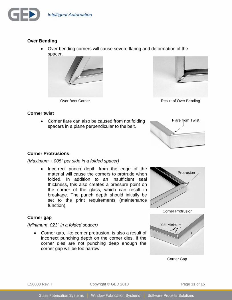
Over Bending • Over bending corners will cause severe flaring and deformation of the
spacer.
Over Bent Corner Result of Over Bending
Corner twist • Corner flare can also be caused from not folding
spacers in a plane perpendicular to the belt.
Corner Protrusions (Maximum +.005” per side in a folded spacer)
• Incorrect punch depth from the edge of the material will cause the corners to protrude when folded. In addition to an insufficient seal thickness, this also creates a pressure point on the corner of the glass, which can result in breakage. The punch depth should initially be set to the print requirements (maintenance function).
Corner gap (Minimum .023" in a folded spacer)
• Corner gap, like corner protrusion, is also a result of incorrect punching depth on the corner dies. If the corner dies are not punching deep enough the corner gap will be too narrow.
Corner Protrusion
Corner Gap
Flare from Twist
Protrusion
.023” Minimum
ES0008 Rev. I Copyright © GED 2010 Page 12 of 15
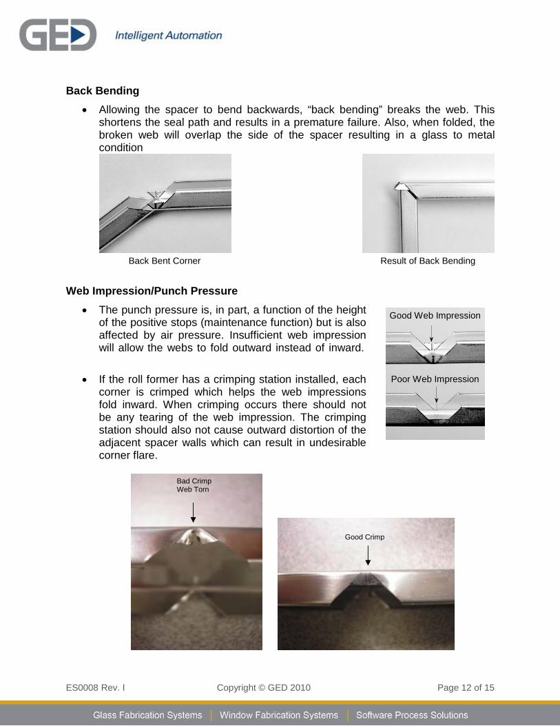
Back Bending • Allowing the spacer to bend backwards, “back bending” breaks the web. This
shortens the seal path and results in a premature failure. Also, when folded, the broken web will overlap the side of the spacer resulting in a glass to metal condition
Back Bent Corner Result of Back Bending
Web Impression/Punch Pressure • The punch pressure is, in part, a function of the height
of the positive stops (maintenance function) but is also affected by air pressure. Insufficient web impression will allow the webs to fold outward instead of inward.
• If the roll former has a crimping station installed, each
corner is crimped which helps the web impressions fold inward. When crimping occurs there should not be any tearing of the web impression. The crimping station should also not cause outward distortion of the adjacent spacer walls which can result in undesirable corner flare.
Bad Crimp Web Torn
Good Crimp
Good Web Impression
Poor Web Impression
ES0008 Rev. I Copyright © GED 2010 Page 13 of 15
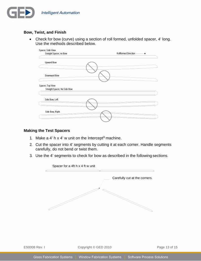
Bow, Twist, and Finish • Check for bow (curve) using a section of roll formed, unfolded spacer, 4’ long.
Use the methods described below.
Spacer, Side View Straight Spacer, no Bow
Rollformed Direction
Spacer, Top View Straight Spacer, No Side Bow
Making the Test Spacers
1. Make a 4’ h x 4’ w unit on the Intercept® machine. 2. Cut the spacer into 4’ segments by cutting it at each corner. Handle segments
carefully, do not bend or twist them. 3. Use the 4’ segments to check for bow as described in the following sections.
Spacer for a 4ft h x 4 ft w unit
Carefully cut at the corners.
Side Bow, Right
Upward Bow
Downward Bow
Side Bow, Left
ES0008 Rev. I Copyright © GED 2010 Page 14 of 15
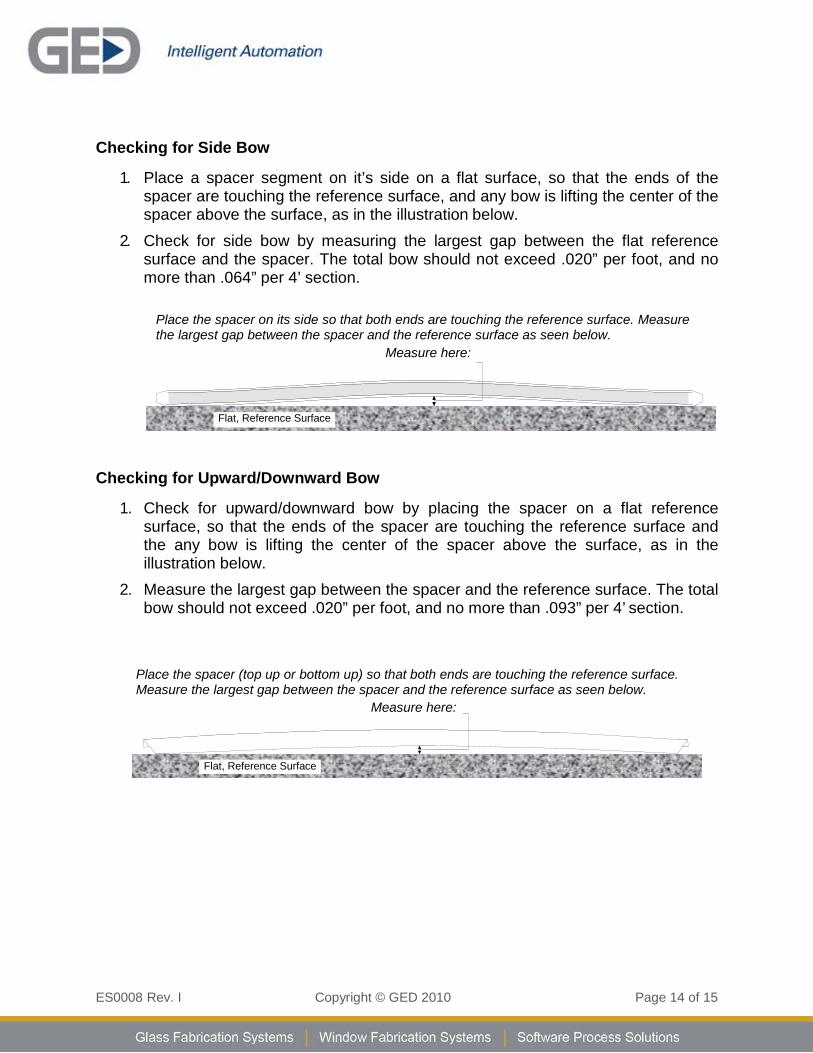
Checking for Side Bow
1. Place a spacer segment on it’s side on a flat surface, so that the ends of the spacer are touching the reference surface, and any bow is lifting the center of the spacer above the surface, as in the illustration below.
2. Check for side bow by measuring the largest gap between the flat reference surface and the spacer. The total bow should not exceed .020” per foot, and no more than .064” per 4’ section.
Place the spacer on its side so that both ends are touching the reference surface. Measure the largest gap between the spacer and the reference surface as seen below.
Measure here:
Checking for Upward/Downward Bow
1. Check for upward/downward bow by placing the spacer on a flat reference surface, so that the ends of the spacer are touching the reference surface and the any bow is lifting the center of the spacer above the surface, as in the illustration below.
2. Measure the largest gap between the spacer and the reference surface. The total bow should not exceed .020” per foot, and no more than .093” per 4’ section.
Place the spacer (top up or bottom up) so that both ends are touching the reference surface. Measure the largest gap between the spacer and the reference surface as seen below.
Measure here:
Flat, Reference Surface
Flat, Reference Surface

ES0008 Rev. I Copyright © GED 2010 Page 15 of 15
Checking for Twist and Finish • Check for twist using one of the spacer segments. The spacer should not twist
more than .015” per 4 foot length.
• Make sure the finish is clean and unblemished.
Additional References: For additional information, please refer to these documents:
Intercept® Raw Material Specifications
• GED Document # ED-0019
Quality Now - PPG IG Quality Assurance Manual
Twist
Flat, Reference Surface