Embed Size (px)
Citation preview
1
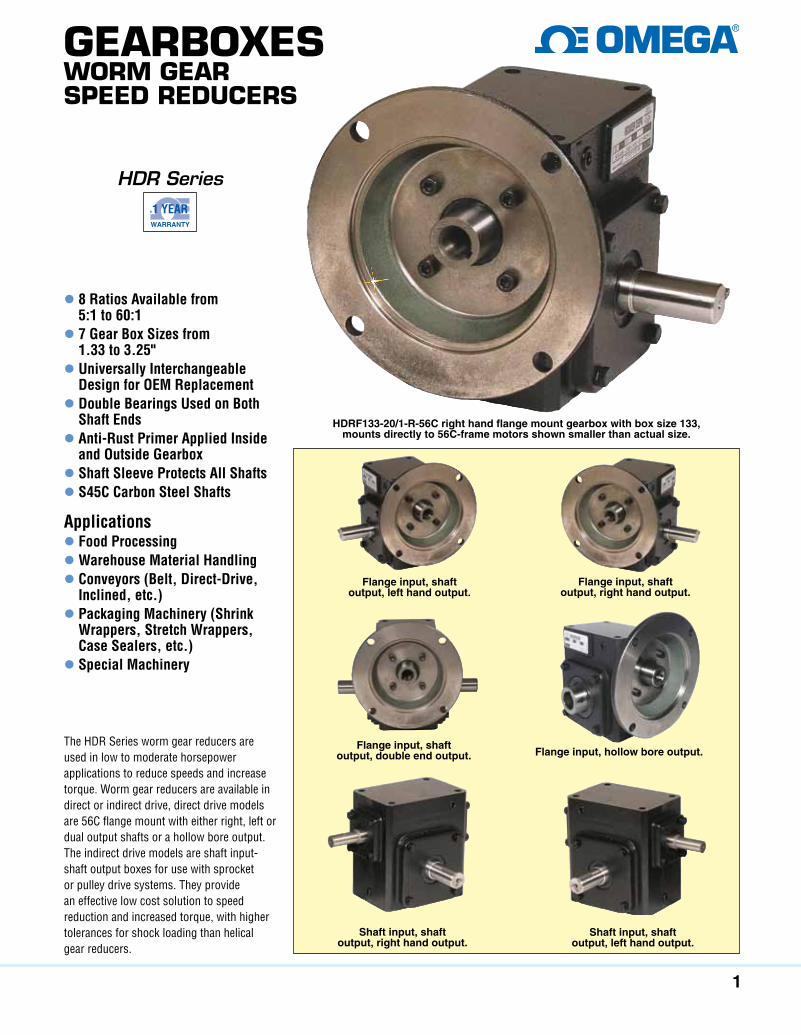
GearboxesWorm Gear speed reducers
HDR Series
l 8 Ratios Available from 5:1 to 60:1
l 7 Gear Box Sizes from 1.33 to 3.25"
l Universally Interchangeable Design for OEM Replacement
l Double Bearings Used on Both Shaft Ends
l Anti-Rust Primer Applied Inside and Outside Gearbox
l Shaft Sleeve Protects All Shaftsl S45C Carbon Steel Shafts Applicationsl Food Processing l Warehouse Material Handling l Conveyors (Belt, Direct-Drive,
Inclined, etc.) l Packaging Machinery (Shrink
Wrappers, Stretch Wrappers, Case Sealers, etc.)
l Special Machinery
The HDR Series worm gear reducers are used in low to moderate horsepower applications to reduce speeds and increase torque. Worm gear reducers are available in direct or indirect drive, direct drive models are 56C flange mount with either right, left or dual output shafts or a hollow bore output. The indirect drive models are shaft input-shaft output boxes for use with sprocket or pulley drive systems. They provide an effective low cost solution to speed reduction and increased torque, with higher tolerances for shock loading than helical gear reducers.
HDRF133-20/1-R-56C right hand flange mount gearbox with box size 133, mounts directly to 56C-frame motors shown smaller than actual size.
Flange input, shaft output, left hand output.
Flange input, hollow bore output.
Flange input, shaft output, right hand output.
Shaft input, shaft output, right hand output.
Shaft input, shaft output, left hand output.
Flange input, shaft output, double end output.
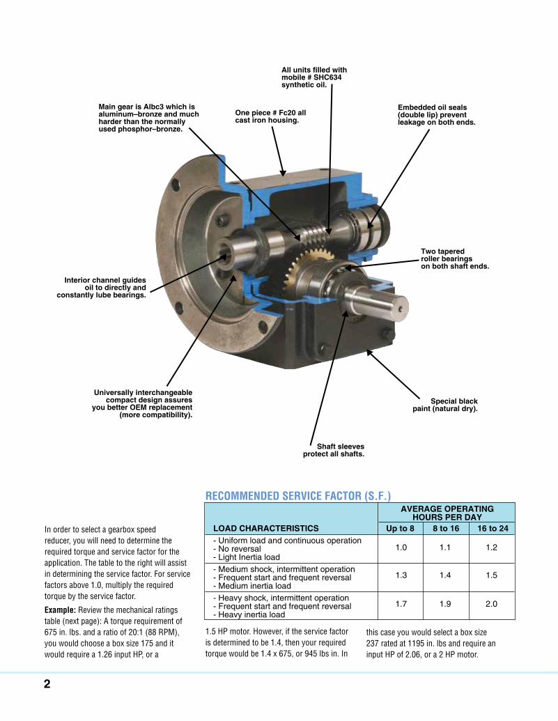
2
AveRAge opeRAting HouRS peR DAy LoAD CHARACteRiStiCS up to 8 8 to 16 16 to 24 - Uniform load and continuous operation - No reversal - Light Inertia load - Medium shock, intermittent operation - Frequent start and frequent reversal - Medium inertia load - Heavy shock, intermittent operation - Frequent start and frequent reversal - Heavy inertia load
1.0 1.1 1.2
1.3 1.4 1.5
1.7 1.9 2.0
In order to select a gearbox speed reducer, you will need to determine the required torque and service factor for the application. The table to the right will assist in determining the service factor. For service factors above 1.0, multiply the required torque by the service factor.
Example: Review the mechanical ratings table (next page): A torque requirement of 675 in. lbs. and a ratio of 20:1 (88 RPM), you would choose a box size 175 and it would require a 1.26 input HP, or a
1.5 HP motor. However, if the service factor is determined to be 1.4, then your required torque would be 1.4 x 675, or 945 lbs in. In
RECOMMENDED SERVICE FACTOR (S.F.)
Main gear is Albc3 which is aluminum–bronze and much harder than the normally used phosphor–bronze.
one piece # Fc20 all cast iron housing.
All units filled with mobile # SHC634 synthetic oil.
embedded oil seals (double lip) prevent leakage on both ends.
two tapered roller bearings on both shaft ends.
Special black paint (natural dry).
Shaft sleeves protect all shafts.
universally interchangeable compact design assures
you better oeM replacement (more compatibility).
interior channel guides oil to directly and
constantly lube bearings.
this case you would select a box size 237 rated at 1195 in. lbs and require an input HP of 2.06, or a 2 HP motor.
3
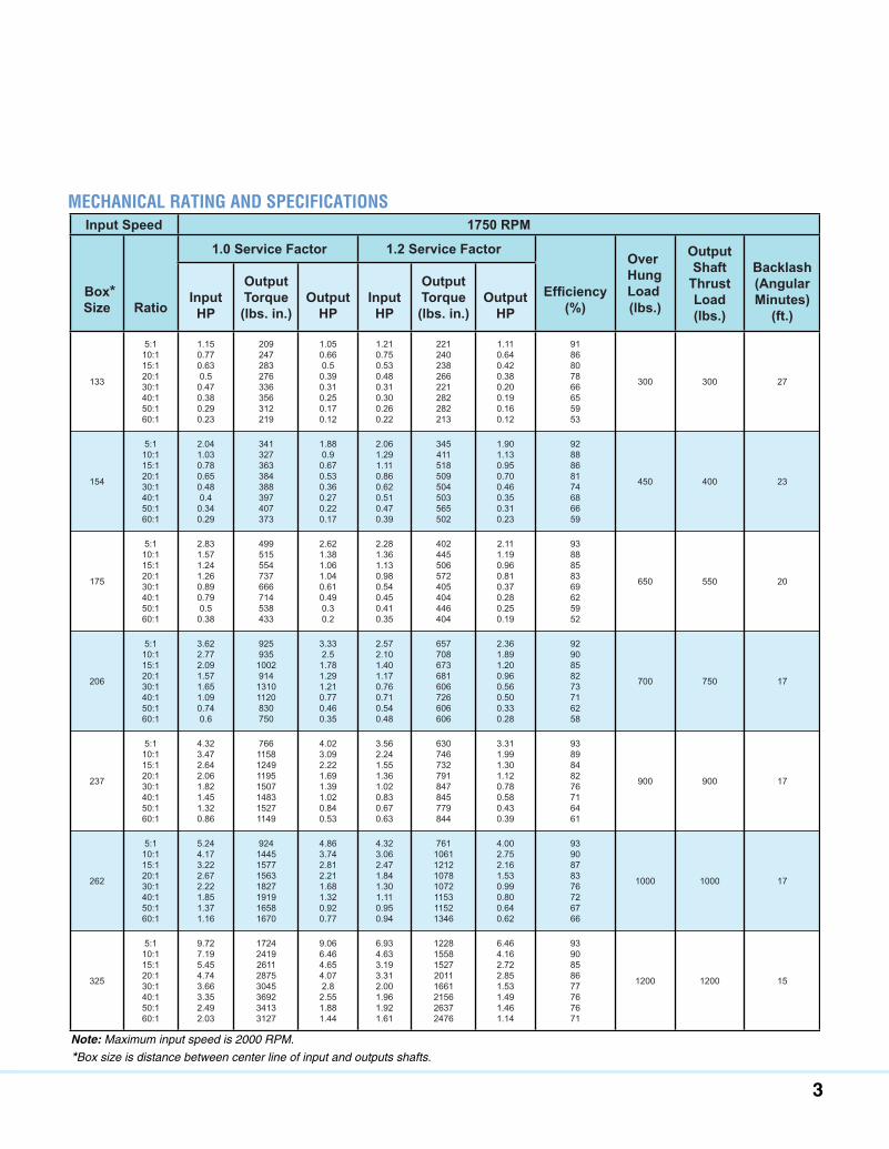
MECHANICAl RATING AND SPECIFICATIONSInput Speed 1750 RPM
Box*Size Ratio
1.0 Service Factor 1.2 Service Factor
(%)
OverHungLoad (lbs.)
OutputShaft
ThrustLoad(lbs.)
Backlash(AngularMinutes)
(ft.)InputHP
OutputTorque(lbs. in.)
OutputHP
InputHP
OutputTorque(lbs. in.)
OutputHP
133
5:110:115:120:130:140:150:160:1
1.150.770.630.50.470.380.290.23
209247283276336356312219
1.050.660.50.390.310.250.170.12
1.210.750.530.480.310.300.260.22
221240238266221282282213
1.110.640.420.380.200.190.160.12
9186807866655953
300 300 27
154
5:110:115:120:130:140:150:160:1
2.041.030.780.650.480.40.340.29
341327363384388397407373
1.880.90.670.530.360.270.220.17
2.061.291.110.860.620.510.470.39
345411518509504503565502
1.901.130.950.700.460.350.310.23
9288868174686659
450 400 23
175
5:110:115:120:130:140:150:160:1
2.831.571.241.260.890.790.50.38
499515554737666714538433
2.621.381.061.040.610.490.30.2
2.281.361.130.980.540.450.410.35
402445506572405404446404
2.111.190.960.810.370.280.250.19
9388858369625952
650 550 20
206
5:110:115:120:130:140:150:160:1
3.622.772.091.571.651.090.740.6
925935100291413101120830750
3.332.51.781.291.210.770.460.35
2.572.101.401.170.760.710.540.48
657708673681606726606606
2.361.891.200.960.560.500.330.28
9290858273716258
700 750 17
237
5:110:115:120:130:140:150:160:1
4.323.472.642.061.821.451.320.86
7661158124911951507148315271149
4.023.092.221.691.391.020.840.53
3.562.241.551.361.020.830.670.63
630746732791847845779844
3.311.991.301.120.780.580.430.39
9389848276716461
900 900 17
262
5:110:115:120:130:140:150:160:1
5.244.173.222.672.221.851.371.16
9241445157715631827191916581670
4.863.742.812.211.681.320.920.77
4.323.062.471.841.301.110.950.94
7611061121210781072115311521346
4.002.752.161.530.990.800.640.62
9390878376726766
1000 1000 17
325
5:110:115:120:130:140:150:160:1
9.727.195.454.743.663.352.492.03
17242419261128753045369234133127
9.066.464.654.072.82.551.881.44
6.934.633.193.312.001.961.921.61
12281558152720111661215626372476
6.464.162.722.851.531.491.461.14
9390858677767671
1200 1200 15
Note: Maximum input speed is 2000 RPM.
*Box size is distance between center line of input and outputs shafts.
4
To Order MoDeL no. Box Size HDRBASe133 133
HDRBASe154 154
HDRBASe175 175
HDRBASe206 206 HDRBASe237 237 HDRBASe262 262 HDRBASe325 325
Box Size A B C D e F t d d1 133 82.5 (3.25) 51 (2) 84 (3.31) 111 (4.38) 106 (4.19) 137 (5.38) 0.53 11⁄32 3⁄8 154 106 (4.19) 70 (2.75) 109 (4.31) 133 (5.25) 138 (5.44) 164 (6.44) 0.59 11⁄32 3⁄8 175 106 (4.19) 70 (2.75) 114 (4.5) 146 (5.75) 145 (5.69) 178 (7) 0.69 13⁄32 3⁄8 206 127 (5) 73 (2.88) 119 (4.69) 162 (6.38) 151 (5.94) 192 (7.55) 0.72 15⁄32 7⁄16
237 127 (5) 73 (2.88) 124 (4.88) 179 (7.06) 158 (6.22) 216 (8.5) 0.75 15⁄32 7⁄16
262 162 (6.38) 86 (3.38) 133 (5.25) 203 (8) 169 (6.66) 245 (9.63) 0.75 17⁄32 7⁄16
325 190 (7.5) 102 (4) 156 (6.13) 241 (9.5) 195 (7.66) 284 (11.19) 0.88 17⁄32 1⁄2
Ad (4) t
B C E
d1 (4)D
F Dimensions: mm (in)
Mounting Base
RAtio 5:1 10:1 15:1 20:1 30:1 40:1 50:1 60:1 RpM @ 1750 input SpeeD 350 175 120 88 58 44 35 29 RAtio CoDe 5/1 10/1 15/1 20/1 30/1 40/1 50/1 60/1
MOUNTING BASES
HDRBASe133 shown smaller than actual size.
Mounting base comes complete with bolts.
5
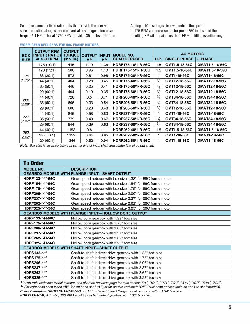
* Insert ratio code into model number, see chart on previous page for ratio codes; “5/1”, “10/1”, “15/1”, “20/1”, “30/1”, “40/1”, “50/1”, “60/1”.** For right hand shaft insert “R”, for left hand shaft “L”, or for double end shaft “DE” (dual shaft not available on shaft-to-shaft models).Order Examples: HDRF154-15/1-R-56C, for 15:1 ratio right hand flange mount gearbox, with a 1.54" box size. HDRS133-5/1-R, 5:1 ratio, 350 RPM shaft input-shaft output gearbox with 1.33" box size.
output RpM output Box input ( RAtio) toRque output input MoDeL no. AC MotoRS Size at 1800 RpM (lbs. in.) Hp Hp geAR ReDuCeR H.p. SingLe pHASe 3-pHASe 175 (10:1) 445 1.19 1.36 HDRF175-10/1-R-56C 1.5 oMt1.5-18-56C oMAt1.5-18-56C 120 (15:1) 506 0.96 1.13 HDRF175-15/1-R-56C 1.5 oMt1.5-18-56C oMAt1.5-18-56C 175 88 (20:1) 572 0.81 0.98 HDRF175-20/1-R-56C 1 oMt1-18-56C oMAt1-18-56C (1.75") 44 (40:1) 404 0.28 0.45 HDRF175-40/1-R-56C 1⁄2 oMt12-18-56C oMAt12-18-56C 35 (50:1) 446 0.25 0.41 HDRF175-50/1-R-56C 1⁄2 oMt12-18-56C oMAt12-18-56C 29 (60:1) 404 0.19 0.35 HDRF175-60/1-R-56C 1⁄2 oMt12-18-56C oMAt12-18-56C
206 44 (40:1) 726 0.5 0.71 HDRF206-40/1-R-56C 3⁄4 oMt34-18-56C oMAt34-18-56C
(2.06") 35 (50:1) 606 0.33 0.54 HDRF206-50/1-R-56C 3⁄4 oMt34-18-56C oMAt34-18-56C 29 (60:1) 606 0.28 0.48 HDRF206-60/1-R-56C 1⁄2 oMt12-18-56C oMAt12-18-56C
237 44 (40:1) 845 0.58 0.83 HDRF237-40/1-R-56C 1 oMt1-18-56C oMAt1-18-56C
(2.37") 35 (50:1) 779 0.43 0.67 HDRF237-50/1-R-56C 3⁄4 oMt34-18-56C oMAt34-18-56C 29 (60:1) 844 0.39 0.63 HDRF237-60/1-R-56C 3⁄4 oMt34-18-56C oMAt34-18-56C
262 44 (40:1) 1153 0.8 1.11 HDRF262-40/1-R-56C 1.5 oMt1.5-18-56C oMAt1.5-18-56C
(2.62") 35 ( 50:1) 1152 0.64 0.95 HDRF262-50/1-R-56C 1 oMt1-18-56C oMAt1-18-56C 29 (60:1) 1346 0.62 0.94 HDRF262-60/1-R-56C 1 oMt1-18-56C oMAt1-18-56C
WORM GEAR REDUCERS FOR 56C FRAME MOTORS
Note: Box size is distance between center line of input shaft and center line of output shaft.
Gearboxes come in fixed ratio units that provide the user with speed reduction along with a mechanical advantage to increase torque. A 1 HP motor at 1750 RPM provides 35 in. lbs. of torque.
Adding a 10:1 ratio gearbox will reduce the speed to 175 RPM and increase the torque to 350 in. lbs. and the resulting HP will remain close to 1 HP with little loss efficiency.
To Order MoDeL no. DeSCRiption geARBox MoDeLS WitH FLAnge input —SHAFt output HDRF133-*-**-56C Gear speed reducer with box size 1.33" for 56C frame motor HDRF154-*-**-56C Gear speed reducer with box size 1.54" for 56C frame motor HDRF175-*-**-56C Gear speed reducer with box size 1.75" for 56C frame motor HDRF206-*-**-56C Gear speed reducer with box size 2.06" for 56C frame motor HDRF237-*-**-56C Gear speed reducer with box size 2.37" for 56C frame motor HDRF262-*-**-56C Gear speed reducer with box size 2.62" for 56C frame motor HDRF325-*-**-56C Gear speed reducer with box size 3.25" for 56C frame motor geARBox MoDeLS WitH FLAnge input—HoLLoW BoRe output HDRF133-*-H-56C Hollow bore gearbox with 1.33" box size HDRF175-*-H-56C Hollow bore gearbox with 1.75" box size HDRF206-*-H-56C Hollow bore gearbox with 2.06" box size HDRF237-*-H-56C Hollow bore gearbox with 2.37" box size HDRF262-*-H-56C Hollow bore gearbox with 2.62" box size HDRF325-*-H-56C Hollow bore gearbox with 3.25" box size geARBox MoDeLS WitH SHAFt input—SHAFt output HDRS133-*-** Shaft-to-shaft indirect drive gearbox with 1.33" box size HDRS175-*-** Shaft-to-shaft indirect drive gearbox with 1.75" box size HDRS206-*-** Shaft-to-shaft indirect drive gearbox with 2.06" box size HDRS237-*-** Shaft-to-shaft indirect drive gearbox with 2.37" box size HDRS262-*-** Shaft-to-shaft indirect drive gearbox with 2.62" box size HDRS325-*-** Shaft-to-shaft indirect drive gearbox with 3.25" box size
![[3] involuteΣ Worm Gear Design System · [3] involuteΣ Worm Gear Design System Fig. 3.1 involuteΣ Worm Gear Design System 3.1 Introduction The involuteΣ Worm Gear Design System](https://img.pdfslide.us/doc/110x75/5eadff0184c9a55408434a64/3-involute-worm-gear-design-3-involute-worm-gear-design-system-fig-31.jpg)