Embed Size (px)
Citation preview

MISCELLANY
MISCELLANY
arc
.id.au
MISCELLANEOUS TECHNICAL ARTICLES BY A R COLLINS
CALENDARS
Historical Calendar
CANVAS GRAPHICS
Cango Graphics Library
Cango User Guide
Cango Axes Extensions
Canvas Layers
Canvas 3D Graphics
Cango3D User Guide
Javascript Graphics Shell
Drawing Gears
JAVASCRIPT ANIMATION
Javascript Animation
Javascript Xeyes
SIGNAL PROCESSING
Spectrum Analyser
FIR Filter Design
Zoom FFT
UNDERWATER ACOUSTICS
Sound Propagation
Sound Pressure Levels
HISTORIC ORDNANCE
Royal Ordnance 1637
British Cannon Design
Cannonball Sizes
Cannonball Aerodynamic Drag
Smooth Bore Cannon Ballistics
Robins On Ballistics
Flintlock Animation
Gear Drawing with Bezier Curves
Introduction
Spur gear tooth profiles are shaped as circle involute curves. The involute is generated from its base circle as if a taut
line were unwound from the circumference, the end of that line would describe a circle involute. The involute is a
transcendental function usually drawn by calculating coordinates of many points along the curve and plotting straight
Gear Drawing with Bezier Curves http://arc.id.au/GearDrawing.html
1 of 12 8/06/2013 9:53 PM
line segments between them.
In an effort to simplify the drafting of circular involute functions, Fumitaka Higuchi et al [1] developed a method of
approximating the involute using Bezier curves. The result is a smooth, quite accurate approximation, suitable for
CAD. The Bezier curve is defined by just a few control points and maintains it shape under 3D transformation. This
greatly reduces the computational load required for drafting.
Set out here is a brief description of the Higuchi method, along with a JavaScript implementation. The accuracy of the
approximation is calculated and examples of drawing gears with the Bezier curves are shown.
Circle involute parametric equations
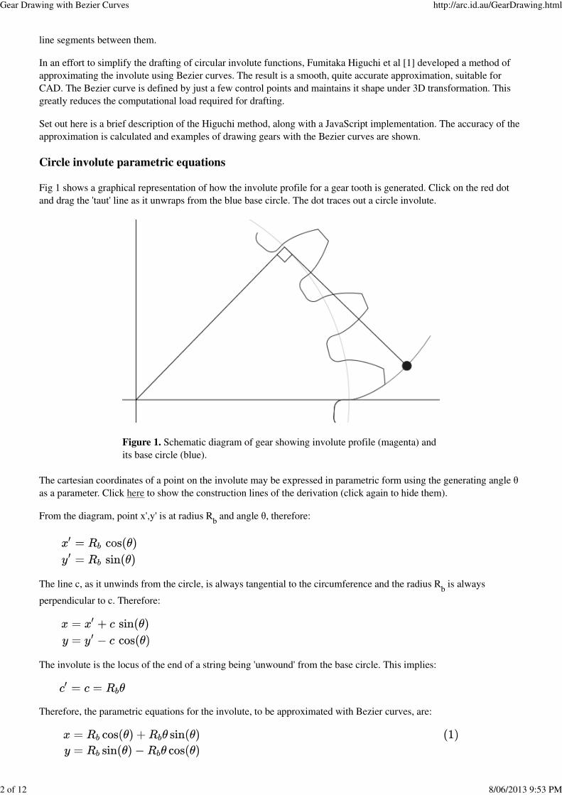
Fig 1 shows a graphical representation of how the involute profile for a gear tooth is generated. Click on the red dot
and drag the 'taut' line as it unwraps from the blue base circle. The dot traces out a circle involute.
The cartesian coordinates of a point on the involute may be expressed in parametric form using the generating angle θ
as a parameter. Click here to show the construction lines of the derivation (click again to hide them).
From the diagram, point x',y' is at radius Rb and angle θ, therefore:
The line c, as it unwinds from the circle, is always tangential to the circumference and the radius Rb is always
perpendicular to c. Therefore:
The involute is the locus of the end of a string being 'unwound' from the base circle. This implies:
Therefore, the parametric equations for the involute, to be approximated with Bezier curves, are:
Figure 1. Schematic diagram of gear showing involute profile (magenta) and
its base circle (blue).
Gear Drawing with Bezier Curves http://arc.id.au/GearDrawing.html
2 of 12 8/06/2013 9:53 PM
Involute Gear Tooth profile dimensions
The geometry of a gear is set by the following basic factors:
the module value, m,
the number of gear teeth Z,
and the pressure angle φ.
The pitch circle diameter D, involute base circle radius Rb and addendum circle radius R
a are related by the formulae:
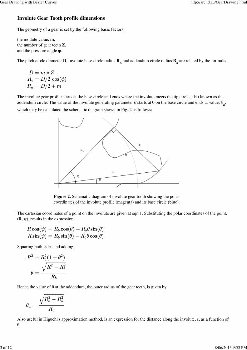
The involute gear profile starts at the base circle and ends where the involute meets the tip circle, also known as the
addendum circle. The value of the involute generating parameter θ starts at 0 on the base circle and ends at value, θa,
which may be calculated the schematic diagram shown in Fig. 2 as follows:
The cartesian coordinates of a point on the involute are given at eqn 1. Substituting the polar coordinates of the point,
(R, ψ), results in the expression:
Squaring both sides and adding:
Hence the value of θ at the addendum, the outer radius of the gear teeth, is given by
Also useful in Higuchi's approximation method, is an expression for the distance along the involute, s, as a function of
θ.
Figure 2. Schematic diagram of involute gear tooth showing the polar
coordinates of the involute profile (magenta) and its base circle (blue).
Gear Drawing with Bezier Curves http://arc.id.au/GearDrawing.html
3 of 12 8/06/2013 9:53 PM
Higuchi et al involute approximation method
The first step in the Higuchi method [1] is to approximate the circle involute curve using the Chebyshev
approximation formula which expresses the curve as a truncated series of polynomials. This requires mapping θ onto
the -1..+1 range expected by the Chebyshev formula. The terms of the series are then recombined to represent the
Bernstein polynomial form (the basis of Bezier curves). A further parameter mapping of the Chebyshev parameter
onto the 0..1 range for the Bezier parameter is required.
The radius of curvature of the involute varies along its length, starting from zero at its on the base circle. This
singularity generates a corresponding singularity in the Bezier approximation, resulting in a double control point at the
base circle. Higuchi suggests avoiding this wasted node by beginning the approximation a short distance from the base
circle, say 1% of the total length.
Higuchi applies this method to a typical gear, having module, 3mm, 17 teeth and pressure angle 25°. Approximation
errors are reported for Bezier approximations of order 4, 6 and 8. These errors are typically a few parts in 106, 109 and
1012 respectively when normalised by the diametral pitch.
JavaScript implementation
A JavaScript implementation of the Higuchi method was written and the source code is available in the file gearUtils-
03.js. This implementation handles any order Bezier curve from 3 upward, with arbitrary start and end points along the
involute.
The JavaScript utility provides the function:
involuteBezCoeffs(module, numTeeth, pressureAngle, order, fstart, fstop)
The required parameters are module, the metric gear size, and numTeeth, the number of teeth. The optional
parameters are: pressureAngle (defaults to 20°), order, the order of the Bezier approximation (defaults to 3), fstart,
the start offset as a proportion of the involute profile length from start to addendum (defaults to 0.01) and fstop, the
stop offset as a fraction of the distance to addendum (defaults to 1). The function returns an array of JavaScript objects
of the form {x:, y:} representing a x,y coordinates of the Bezier curve nodes. For an order N approximation, there will
be N+1 nodes in the array; the start point, N-1 control points and the end point.
Cubic Bezier approximation
The Higuchi technique would be of great benefit in web based gear modelling if it produced accurate approximations
using cubic (order 3) Bezier curves, as the HTML5 canvas element has native support only for quadratic and cubic
Bezier curves.
To test the method's performance, a cubic Bezier curve fit was made to a typical gear profile. The specifications of the
gear used in the example are the same as used in Higuchi's paper, (module=3, teeth=17, pressureAngle=25). Fig. 3
shows a plot of the cubic Bezier curve approximation to the involute (green line). A piece-wise plot of the true
involute, is shown for comparison (magenta line). The Bezier curve control points are shown as crosses.
Gear Drawing with Bezier Curves http://arc.id.au/GearDrawing.html
4 of 12 8/06/2013 9:53 PM

Figure 3. Cubic Bezier approximation to a circular involute (green line) calculated using the Higuchi-Chebyshev
approximation method. The true involute is shown for comparison (magenta line).
Cubic Bezier errors
Table 1 shows the approximation errors for the cubic Bezier approximation to the involute shown in Fig. 3. The errors
are calculated at intervals along the involute. Column 1 shows the distance along the profile as a fraction of total
length. Column 2 shows the errors as the absolute value of the distance of the point on the approximation to the closest
point on the true involute, measured in millimetres. Column 3 shows these error values normalised to the pitch
diameter. The distance of a point from a cubic Bezier curve was calculated using the Bezier utilities library jsBezier.js
written by Simon Porritt.
Distance
along involute
Error
(mm)Error/Diametral Pitch
0.01 0.0486 9.5E-4
0.05 0.0003 5.3E-6
0.11 0.0005 9.3E-6
0.20 0.0049 9.6E-5
0.31 0.0125 2.4E-4
0.44 0.0202 4.0E-4
0.60 0.0221 4.3E-4
0.79 0.0096 1.9E-4
1.00 0.0284 5.6E-4
Table 1. Approximation errors for a single cubic Bezier curve approximation to the involute shown in Fig. 3. Each
error is the distance from a point on the approximation to the closest point on the true involute.
Using a cubic Bezier curve to approximate the full profile length results in normalised errors of a few parts in 104. The
worst errors occur at the extremities, not accurate enough for gear design work.
Two cubic Bezier approximation
The solution to reducing the approximation error is to split the involute into two sections fitting a cubic Bezier curve
to each. This reduces the errors by an order of magnitude, to just of a few parts in 105.
Gear Drawing with Bezier Curves http://arc.id.au/GearDrawing.html
5 of 12 8/06/2013 9:53 PM

The junction point of the two Bezier curves is set 25% along the involute, this helps apportion the curvature to be
modelled between the two curves. The first cubic Bezier starts 1% of the way along the involute to avoid the
duplicated node at the involute singularity. The start point of the second Bezier coincides with the end point of the first
Bezier, so one of these nodes may be discarded. The resulting Bezier approximation has 7 nodes, start, mid and end
points and 4 control points.
Here is an example using the 'involuteBezCoeffs' function to generate the two cubic Bezier curves representing a gear
profile. The gear parameters are the same as the example in the Higuchi paper.
var module = 3;
var teeth = 17;
var pressureAngle = 25;
var Rpitch = module*teeth/2;
var Rb = Rpitch * Math.cos(pressureAngle*Math.PI/180); // base circle radius
// generate Higuchi involute approximation
var fs = 0.01; // start 1% off the base circle
var fm = 0.25; // break 25% along involute
var fe = 1; // end at 100%
var dedBz = involuteBezCoeffs(module, teeth, pressureAngle, 3, fs, fm);
var addBz = involuteBezCoeffs(module, teeth, pressureAngle, 3, fm, fe);
...
var data = ["M", dedBz[0].x, dedBz[0].y,
"C", dedBz[1].x, dedBz[1].y, dedBz[2].x, dedBz[2].y, dedBz[3].x, dedBz[3].y,
"C", addBz[1].x, addBz[1].y, addBz[2].x, addBz[2].y, addBz[3].x, addBz[3].y];
// draw the involute using Cango library
g.drawPath(data, -Rpitch, 0, 'blue');
Fig. 4 shows a plot of the two cubic Bezier approximation to a circular involute (blue line) calculated by dividing the
involute into two sections and fitting a cubic Bezier to each section using the Higuchi-Chebyshev approximation
method. For comparison the magenta line is the true involute.
Figure 4. A two cubic Bezier approximation to the same circular involute shown in Fig. 3 (blue line). The true
involute, is shown in magenta for comparison.
Two cubic Bezier errors
Table 2 shows the approximation errors at various points along the involute. Column 1 shows the distance along the
involute expressed as a fraction of the total length. Column 2 shows the approximation error, the absolute value of
Gear Drawing with Bezier Curves http://arc.id.au/GearDrawing.html
6 of 12 8/06/2013 9:53 PM
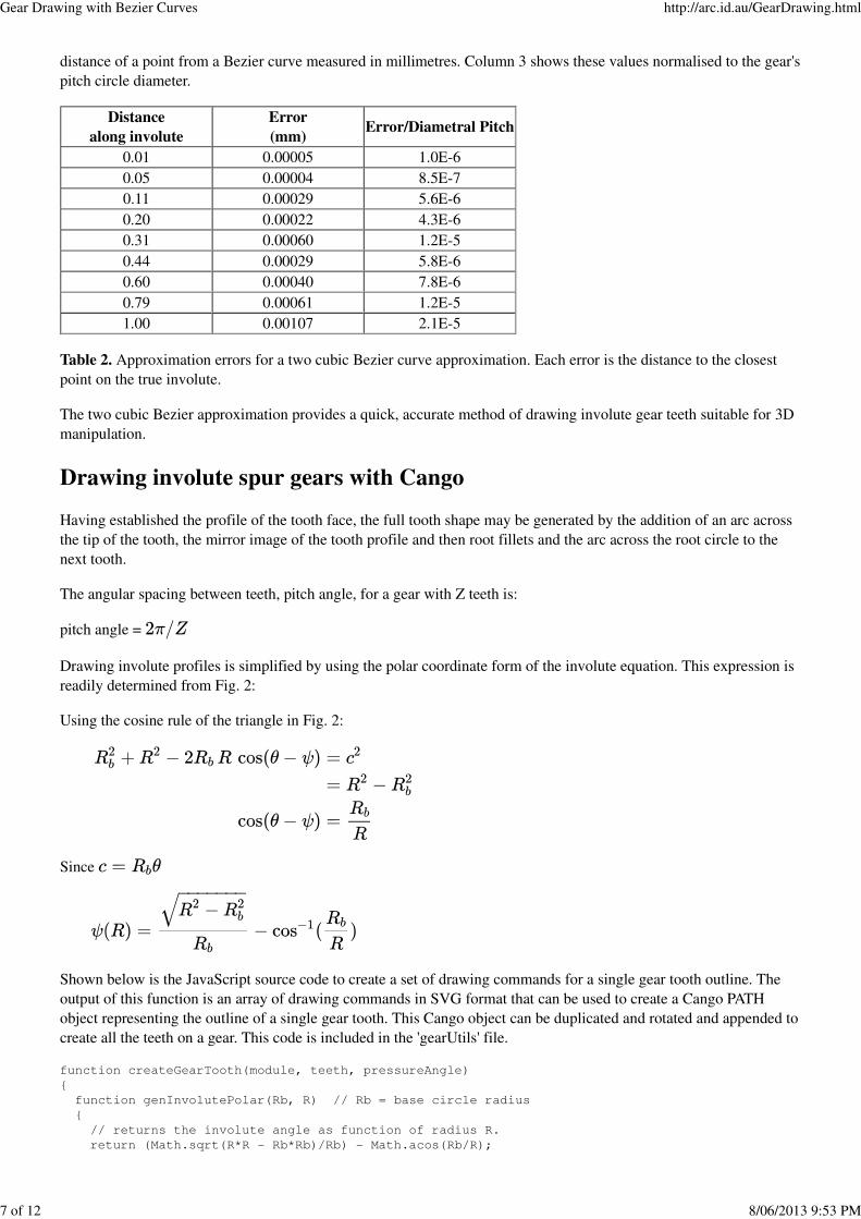
distance of a point from a Bezier curve measured in millimetres. Column 3 shows these values normalised to the gear's
pitch circle diameter.
Distance
along involute
Error
(mm)Error/Diametral Pitch
0.01 0.00005 1.0E-6
0.05 0.00004 8.5E-7
0.11 0.00029 5.6E-6
0.20 0.00022 4.3E-6
0.31 0.00060 1.2E-5
0.44 0.00029 5.8E-6
0.60 0.00040 7.8E-6
0.79 0.00061 1.2E-5
1.00 0.00107 2.1E-5
Table 2. Approximation errors for a two cubic Bezier curve approximation. Each error is the distance to the closest
point on the true involute.
The two cubic Bezier approximation provides a quick, accurate method of drawing involute gear teeth suitable for 3D
manipulation.
Drawing involute spur gears with Cango
Having established the profile of the tooth face, the full tooth shape may be generated by the addition of an arc across
the tip of the tooth, the mirror image of the tooth profile and then root fillets and the arc across the root circle to the
next tooth.
The angular spacing between teeth, pitch angle, for a gear with Z teeth is:
pitch angle =
Drawing involute profiles is simplified by using the polar coordinate form of the involute equation. This expression is
readily determined from Fig. 2:
Using the cosine rule of the triangle in Fig. 2:
Since
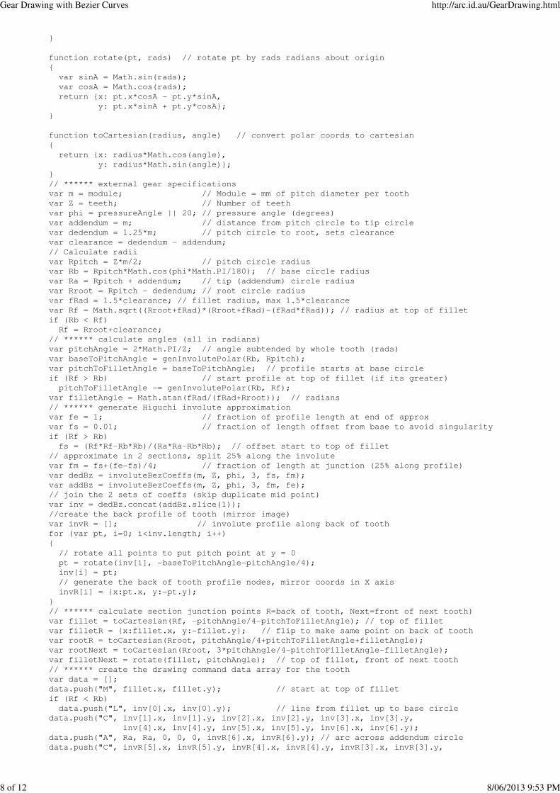
Shown below is the JavaScript source code to create a set of drawing commands for a single gear tooth outline. The
output of this function is an array of drawing commands in SVG format that can be used to create a Cango PATH
object representing the outline of a single gear tooth. This Cango object can be duplicated and rotated and appended to
create all the teeth on a gear. This code is included in the 'gearUtils' file.
function createGearTooth(module, teeth, pressureAngle)
{
function genInvolutePolar(Rb, R) // Rb = base circle radius
{
// returns the involute angle as function of radius R.
return (Math.sqrt(R*R - Rb*Rb)/Rb) - Math.acos(Rb/R);
Gear Drawing with Bezier Curves http://arc.id.au/GearDrawing.html
7 of 12 8/06/2013 9:53 PM
}
function rotate(pt, rads) // rotate pt by rads radians about origin
{
var sinA = Math.sin(rads);
var cosA = Math.cos(rads);
return {x: pt.x*cosA - pt.y*sinA,
y: pt.x*sinA + pt.y*cosA};
}
function toCartesian(radius, angle) // convert polar coords to cartesian
{
return {x: radius*Math.cos(angle),
y: radius*Math.sin(angle)};
}
// ****** external gear specifications
var m = module; // Module = mm of pitch diameter per tooth
var Z = teeth; // Number of teeth
var phi = pressureAngle || 20; // pressure angle (degrees)
var addendum = m; // distance from pitch circle to tip circle
var dedendum = 1.25*m; // pitch circle to root, sets clearance
var clearance = dedendum - addendum;
// Calculate radii
var Rpitch = Z*m/2; // pitch circle radius
var Rb = Rpitch*Math.cos(phi*Math.PI/180); // base circle radius
var Ra = Rpitch + addendum; // tip (addendum) circle radius
var Rroot = Rpitch - dedendum; // root circle radius
var fRad = 1.5*clearance; // fillet radius, max 1.5*clearance
var Rf = Math.sqrt((Rroot+fRad)*(Rroot+fRad)-(fRad*fRad)); // radius at top of fillet
if (Rb < Rf)
Rf = Rroot+clearance;
// ****** calculate angles (all in radians)
var pitchAngle = 2*Math.PI/Z; // angle subtended by whole tooth (rads)
var baseToPitchAngle = genInvolutePolar(Rb, Rpitch);
var pitchToFilletAngle = baseToPitchAngle; // profile starts at base circle
if (Rf > Rb) // start profile at top of fillet (if its greater)
pitchToFilletAngle -= genInvolutePolar(Rb, Rf);
var filletAngle = Math.atan(fRad/(fRad+Rroot)); // radians
// ****** generate Higuchi involute approximation
var fe = 1; // fraction of profile length at end of approx
var fs = 0.01; // fraction of length offset from base to avoid singularity
if (Rf > Rb)
fs = (Rf*Rf-Rb*Rb)/(Ra*Ra-Rb*Rb); // offset start to top of fillet
// approximate in 2 sections, split 25% along the involute
var fm = fs+(fe-fs)/4; // fraction of length at junction (25% along profile)
var dedBz = involuteBezCoeffs(m, Z, phi, 3, fs, fm);
var addBz = involuteBezCoeffs(m, Z, phi, 3, fm, fe);
// join the 2 sets of coeffs (skip duplicate mid point)
var inv = dedBz.concat(addBz.slice(1));
//create the back profile of tooth (mirror image)
var invR = []; // involute profile along back of tooth
for (var pt, i=0; i<inv.length; i++)
{
// rotate all points to put pitch point at y = 0
pt = rotate(inv[i], -baseToPitchAngle-pitchAngle/4);
inv[i] = pt;
// generate the back of tooth profile nodes, mirror coords in X axis
invR[i] = {x:pt.x, y:-pt.y};
}
// ****** calculate section junction points R=back of tooth, Next=front of next tooth)
var fillet = toCartesian(Rf, -pitchAngle/4-pitchToFilletAngle); // top of fillet
var filletR = {x:fillet.x, y:-fillet.y}; // flip to make same point on back of tooth
var rootR = toCartesian(Rroot, pitchAngle/4+pitchToFilletAngle+filletAngle);
var rootNext = toCartesian(Rroot, 3*pitchAngle/4-pitchToFilletAngle-filletAngle);
var filletNext = rotate(fillet, pitchAngle); // top of fillet, front of next tooth
// ****** create the drawing command data array for the tooth
var data = [];
data.push("M", fillet.x, fillet.y); // start at top of fillet
if (Rf < Rb)
data.push("L", inv[0].x, inv[0].y); // line from fillet up to base circle
data.push("C", inv[1].x, inv[1].y, inv[2].x, inv[2].y, inv[3].x, inv[3].y,
inv[4].x, inv[4].y, inv[5].x, inv[5].y, inv[6].x, inv[6].y);
data.push("A", Ra, Ra, 0, 0, 0, invR[6].x, invR[6].y); // arc across addendum circle
data.push("C", invR[5].x, invR[5].y, invR[4].x, invR[4].y, invR[3].x, invR[3].y,
Gear Drawing with Bezier Curves http://arc.id.au/GearDrawing.html
8 of 12 8/06/2013 9:53 PM

invR[2].x, invR[2].y, invR[1].x, invR[1].y, invR[0].x, invR[0].y);
if (Rf < Rb)
data.push("L", filletR.x, filletR.y); // line down to top of fillet
if (rootNext.y > rootR.y) // is there a section of root circle between fillets?
{
data.push("A", fRad, fRad, 0, 0, 1, rootR.x, rootR.y);// back fillet
data.push("A", Rroot, Rroot, 0, 0, 0, rootNext.x, rootNext.y); // root circle arc
}
data.push("A", fRad, fRad, 0, 0, 1, filletNext.x, filletNext.y);
return data; // return an array of Cango (SVG) format draw commands
}
Drawing gears with Cango
To create the outline of a full gear from the profile of the tooth, the Cango PATH object representing one tooth is
created, this is then duplicated, rotated by the pitch angle and appended to the gear object to make each of the gear's
teeth. This gear outline then has a circular axle shaft hole appended, its then ready to be rendered to the screen and
animated. The code snippet to create a gear using Cango is shown below:
var m = module; // Module = mm of pitch diameter per tooth
var Zg = gearTeeth;
var phi = pressureAngle || 20;
var Rg = Zg*m/2; // gear Pitch radius
// generate gear
var data = createGearTooth(m, Zg, phi);
var gearTooth = g.compileShape(data, '#b0a0b0', '#606060');
gearTooth.rotate(180/Zg); // rotate gear 1/2 tooth to mesh
var gear = gearTooth.dup();
for (var i=1, newTooth; i<Zg; i++)
{
newTooth = gearTooth.dup();
newTooth.rotate(360*i/Zg);
gear.appendPath(newTooth, true); // trim 'moveTo' command = true
}
// add axle shaft hole
var Dsg = 0.6*Rg; // diameter of gear shaft
var shaft = g.compilePath(shapeDefs.circle);
shaft.scale(Dsg);
shaft.revWinding();
gear.appendPath(shaft); // retain the 'moveTo' command for shaft subpath
Adding backlash when drawing meshed gears
In practical gearing there is always a gap between the non-drive face of the pinion tooth and the adjacent wheel tooth
to prevent gears from jamming. This gap is termed backlash. If the direction of rotation is reversed, there is a period
during which the pinion moves independently until the backlash gap is taken up and gear tooth contact re-established.
Backlash may be created by cutting the gear spaces a little deeper, so the gaps are wider than the teeth, this method is
preferred for stock gears. Alternatively, backlash may be introduced by increasing the center distance between the
gears. This separation does not affect the speed ratio between the gears or require any alteration to the gear tooth
profile.
Recommended backlash is:
backlash = 0.04*Module
To create this backlash the center distance is increased by ∆C where:
∆C = backlash/2 * tan(phi);
Fig. 5 shows a pair of gears with module value of 5 mm. The pinion has 24 teeth and the gear 52, the pressure angle is
20°. The involute profiles were calculated using the 2 cubic Bezier approximation. Backlash of 0.2 mm was added by
increasing the center distance by 0.275 mm.
Gear Drawing with Bezier Curves http://arc.id.au/GearDrawing.html
9 of 12 8/06/2013 9:53 PM

Figure 5.A spur gear animation drawn with the two cubic Bezier approximation to the involute gear tooth profiles.
Internal gear drawing example
Internal gears, or ring gears, may be drawn with similar efficiency. Shown below is the JavaScript source code to
create the drawing commands for a single internal gear tooth outline. This code is included in the 'gearUtils' file.
function createIntGearTooth(module, teeth, pressureAngle)
{
function genInvolutePolar(Rb, R) // Rb = base circle radius
{
// returns the involute angle as function of radius R.
return (Math.sqrt(R*R - Rb*Rb)/Rb) - Math.acos(Rb/R);
}
function rotate(pt, rads) // rotate pt by rads radians about origin
{
var sinA = Math.sin(rads);
var cosA = Math.cos(rads);
return {x: pt.x*cosA - pt.y*sinA,
y: pt.x*sinA + pt.y*cosA};
}
function toCartesian(radius, angle) // convert polar coords to cartesian
{
return {x: radius*Math.cos(angle),
y: radius*Math.sin(angle)};
}
// ****** gear specifications
var m = module; // Module = mm of pitch diameter per tooth
var Z = teeth; // Number of teeth
var phi = pressureAngle || 20;// pressure angle (degrees)
var addendum = 0.6*m; // pitch circle to tip circle (ref G.M.Maitra)
var dedendum = 1.25*m; // pitch circle to root radius, sets clearance
// Calculate radii
var Rpitch = Z*m/2; // pitch radius
var Rb = Rpitch*Math.cos(phi*Math.PI/180); // base radius
var Ra = Rpitch - addendum; // addendum radius
var Rroot = Rpitch + dedendum;// root radius
var clearance = 0.25*m; // gear dedendum - pinion addendum
var Rf = Rroot - clearance; // radius of top of fillet (end of profile)
var fRad = 1.5*clearance; // fillet radius, 1 .. 1.5*clearance
// ****** calculate subtended angles
Gear Drawing with Bezier Curves http://arc.id.au/GearDrawing.html
10 of 12 8/06/2013 9:53 PM
var pitchAngle = 2*Math.PI/Z; // angle between teeth (rads)
var baseToPitchAngle = genInvolutePolar(Rb, Rpitch);
var tipToPitchAngle = baseToPitchAngle; // profile starts from base circle
if (Ra > Rb)
tipToPitchAngle -= genInvolutePolar(Rb, Ra); // start profile from addendum
var pitchToFilletAngle = genInvolutePolar(Rb, Rf) - baseToPitchAngle;
var filletAngle = 1.414*clearance/Rf; // to make fillet tangential to root
// ****** generate Higuchi involute approximation
var fe = 1; // fraction of involute length at end of approx (fillet circle)
var fs = 0.01 // fraction of length offset from base to avoid singularity
if (Ra > Rb)
fs = (Ra*Ra-Rb*Rb)/(Rf*Rf-Rb*Rb); // start profile from addendum (tip circle)
// approximate in 2 sections, split 25% along the profile
var fm = fs+(fe-fs)/4; //
var addBz = involuteBezCoeffs(m, Z, phi, 3, fs, fm);
var dedBz = involuteBezCoeffs(m, Z, phi, 3, fm, fe);
// join the 2 sets of coeffs (skip duplicate mid point)
var invR = addBz.concat(dedBz.slice(1));
//create the front profile of tooth (mirror image)
var inv = []; // back involute profile
for (var pt, i=0; i<invR.length; i++)
{
// rotate involute to put center of tooth at y = 0
pt = rotate(invR[i], pitchAngle/4-baseToPitchAngle);
invR[i] = pt;
// generate the back of tooth profile, flip Y coords
inv[i] = {x:pt.x, y:-pt.y};
}
// ****** calculate coords of section junctions
var fillet = {x:inv[6].x, y:inv[6].y}; // top of fillet, front of tooth
var tip = toCartesian(Ra, -pitchAngle/4+tipToPitchAngle); // tip, front of tooth
var tipR = {x:tip.x, y:-tip.y}; // addendum, back of tooth
var rootR = toCartesian(Rroot, pitchAngle/4+pitchToFilletAngle+filletAngle);
var rootNext = toCartesian(Rroot, 3*pitchAngle/4-pitchToFilletAngle-filletAngle);
var filletNext = rotate(fillet, pitchAngle); // top of fillet, front of next tooth
// ****** create the drawing command data array for the tooth
var data = [];
data.push("M", inv[6].x, inv[6].y); // start at top of front profile
data.push("C", inv[5].x, inv[5].y, inv[4].x, inv[4].y, inv[3].x, inv[3].y,
inv[2].x, inv[2].y, inv[1].x, inv[1].y, inv[0].x, inv[0].y);
if (Ra < Rb)
data.push("L", tip.x, tip.y); // line from end of involute to addendum (tip)
data.push("A", Ra, Ra, 0, 0, 0, tipR.x, tipR.y); // arc across tip circle
if (Ra < Rb)
data.push("L", invR[0].x, invR[0].y); // line from addendum to start of involute
data.push("C", invR[1].x, invR[1].y, invR[2].x, invR[2].y, invR[3].x, invR[3].y,
invR[4].x, invR[4].y, invR[5].x, invR[5].y, invR[6].x, invR[6].y);
if (rootR.y < rootNext.y) // there is a section of root circle between fillets
{
data.push("A", fRad, fRad, 0, 0, 0, rootR.x, rootR.y); // fillet on back of tooth
data.push("A", Rroot, Rroot, 0, 0, 0, rootNext.x, rootNext.y); // root circle arc
}
data.push("A", fRad, fRad, 0, 0, 0, filletNext.x, filletNext.y); // fillet on next
return data; // return an array of Cango (SVG) format draw commands
}
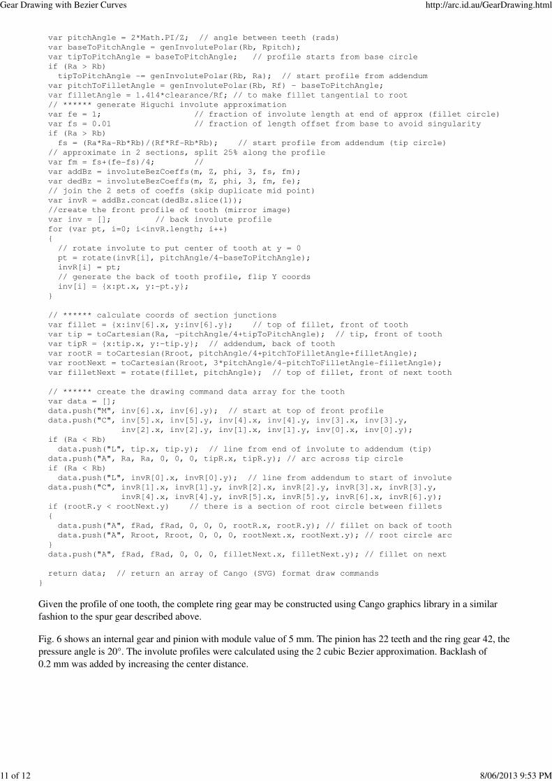
Given the profile of one tooth, the complete ring gear may be constructed using Cango graphics library in a similar
fashion to the spur gear described above.
Fig. 6 shows an internal gear and pinion with module value of 5 mm. The pinion has 22 teeth and the ring gear 42, the
pressure angle is 20°. The involute profiles were calculated using the 2 cubic Bezier approximation. Backlash of
0.2 mm was added by increasing the center distance.
Gear Drawing with Bezier Curves http://arc.id.au/GearDrawing.html
11 of 12 8/06/2013 9:53 PM

Figure 6. An internal gear animation, drawn with the two cubic Bezier approximation to the involute gear tooth
profiles.
The Higuchi method has proven to be applicable to gear drawing on the HTML5 canvas element despite the limitation
to order 3 Bezier approximation that the canvas imposes. All the source code used on this page is released free for
non-commercial use.
References:
1. F.Higuchi, S. Gofuku, T. Maekawa, H. Mukundan, N.M. Patrikalakis, YNU Digital Eng Lab Memorandum 05-1 2006.
2. G.M.Maitra, Handbook of Gear Design, 1994
Gear Drawing with Bezier Curves http://arc.id.au/GearDrawing.html
12 of 12 8/06/2013 9:53 PM


![Curves and Surfacesadair/CG/Notas Aula/Curvas/09-curves.pdf · Bezier Curves and Surfaces [Angel 10.1-10.6] Parametric Representations Cubic Polynomial Forms Hermite Curves Bezier](https://img.pdfslide.us/doc/110x75/5f72f8d58557ce2aea5f374f/curves-and-adaircgnotas-aulacurvas09-curvespdf-bezier-curves-and-surfaces.jpg)