Embed Size (px)
Citation preview
Faculty of Engineering
GEAR AND SHAFT DESIGN
Project 2ME-321 - Kinematics and Dynamics of Machines
Prepared byPavel SheringID #20523043
Instructor: Eihab Abdel-Rahman3a Mechatronics Engineering
July 5, 2016
Table of Contents
1 Problem Details . . . . . . . . . . . . . . . . . . . . . . . . . 1
2 Gear Design . . . . . . . . . . . . . . . . . . . . . . . . . . . 22.1 Gear A (pinion) & B (gear) . . . . . . . . . . . . . . . . . . . 2
2.1.1 Bending Stress . . . . . . . . . . . . . . . . . . . . . . 32.1.2 Contact Stress . . . . . . . . . . . . . . . . . . . . . . 6
2.2 Gear C (pinion) & D (gear) . . . . . . . . . . . . . . . . . . . 82.2.1 Bending Stress . . . . . . . . . . . . . . . . . . . . . . 92.2.2 Contact Stress . . . . . . . . . . . . . . . . . . . . . . 12
3 Shaft Design . . . . . . . . . . . . . . . . . . . . . . . . . . . 153.1 Motor Shaft Force Analysis . . . . . . . . . . . . . . . . . . . 153.2 Reducer Shaft (Shaft 1) Force Analysis . . . . . . . . . . . . . 16
3.2.1 Reducer Shaft 1 Arrangement and Specifications . . . 183.3 Reducer Middle Shaft (Shaft 2) Force Analysis . . . . . . . . 23
3.3.1 Reducer Shaft 2 Arrangement and Specifications . . . 273.4 Output Reducer Shaft (Shaft 3) Force Analysis . . . . . . . . 31
3.4.1 Reducer Shaft 3 Arrangement and Specifications . . . 33
4 Conclusion . . . . . . . . . . . . . . . . . . . . . . . . . . . . 40
5 References . . . . . . . . . . . . . . . . . . . . . . . . . . . . 41
i
List of Figures
1 Full system diagram . . . . . . . . . . . . . . . . . . . . . . . 1
2 Reducer Diagram . . . . . . . . . . . . . . . . . . . . . . . . . 1
3 Input Sheave coupled to the Motor Shaft with a belt drive . . 15
4 Shaft 1 Free Body Diagram . . . . . . . . . . . . . . . . . . . 17
5 Shaft 1 Torque Diagram . . . . . . . . . . . . . . . . . . . . . 17
6 Shaft 1 Shear and Moment Diagram . . . . . . . . . . . . . . . 18
7 Shaft 1 Design . . . . . . . . . . . . . . . . . . . . . . . . . . . 19
8 Shaft 2 Free Body Diagram . . . . . . . . . . . . . . . . . . . 24
9 Shaft 2 Torque Diagram . . . . . . . . . . . . . . . . . . . . . 25
10 Shaft 2 Shear and Moment Diagram . . . . . . . . . . . . . . . 26
11 Shaft 2 Design . . . . . . . . . . . . . . . . . . . . . . . . . . . 27
12 Output Gear D coupled to the Conveyor with a chain drive . . 31
13 Shaft 3 Free Body Diagram . . . . . . . . . . . . . . . . . . . 32
14 Shaft 3 Torque Diagram . . . . . . . . . . . . . . . . . . . . . 33
15 Shaft 3 Shear and Moment Diagram . . . . . . . . . . . . . . . 34
16 Shaft 3 Design . . . . . . . . . . . . . . . . . . . . . . . . . . . 34
ii
List of Tables
1 Gear A & B Properties . . . . . . . . . . . . . . . . . . . . . . 4
2 Bending Stress Paramters . . . . . . . . . . . . . . . . . . . . 5
3 Gear C & D Properties . . . . . . . . . . . . . . . . . . . . . . 10
4 Bending Stress Paramters . . . . . . . . . . . . . . . . . . . . 11
5 SAE 1040 CD Steel Properties . . . . . . . . . . . . . . . . . . 15
6 Combined Shear and Bending Moment Forces . . . . . . . . . 18
7 Shared Parameters for all Shafts . . . . . . . . . . . . . . . . . 19
8 Parameters for D1 . . . . . . . . . . . . . . . . . . . . . . . . 20
9 Parameters for D′1 . . . . . . . . . . . . . . . . . . . . . . . . 20
10 Parameters for D2 . . . . . . . . . . . . . . . . . . . . . . . . 21
11 Parameters for D4 . . . . . . . . . . . . . . . . . . . . . . . . 22
12 Parameters for D′4 . . . . . . . . . . . . . . . . . . . . . . . . 22
13 Parameters for D5 . . . . . . . . . . . . . . . . . . . . . . . . 23
14 Required Diameters for Shaft 1 . . . . . . . . . . . . . . . . . 24
15 Combined Shear and Bending Moment Forces . . . . . . . . . 26
16 Parameters for D1 . . . . . . . . . . . . . . . . . . . . . . . . 27
17 Parameters for D2 . . . . . . . . . . . . . . . . . . . . . . . . 28
18 Parameters for D′2 . . . . . . . . . . . . . . . . . . . . . . . . 28
19 Parameters for D4 . . . . . . . . . . . . . . . . . . . . . . . . 29
20 Parameters for D′4 . . . . . . . . . . . . . . . . . . . . . . . . 29
21 Parameters for D5 . . . . . . . . . . . . . . . . . . . . . . . . 30
22 Required Diameters for Shaft 2 . . . . . . . . . . . . . . . . . 31
23 Combined Shear and Bending Moment Forces . . . . . . . . . 34
24 Parameters for D1 . . . . . . . . . . . . . . . . . . . . . . . . 35
25 Parameters for D2 . . . . . . . . . . . . . . . . . . . . . . . . 35
26 Parameters for D′2 . . . . . . . . . . . . . . . . . . . . . . . . 36
27 Parameters for D4 . . . . . . . . . . . . . . . . . . . . . . . . 37
28 Parameters for D5 . . . . . . . . . . . . . . . . . . . . . . . . 37
29 Parameters for D′5 . . . . . . . . . . . . . . . . . . . . . . . . 38
30 Required Diameters for Shaft 3 . . . . . . . . . . . . . . . . . 39
iii

1 Problem Details
The purpose of this report is to design a system to power the conveyor driven
machine with a 12.0 horse power, 1150 rpm motor under the assumption that
each shaft in the system transmits 12.0 hp. The system is to consist of v-belt
driven input shaft connected to the motor, a 6:1 reducer and an output shaft
connected to the conveyor through a chain drive delivering the power form the
motor.
Figures 1 and 2 illustrate the system problem. The gears of the system are
designed first, as
Figure 1: Full system diagram
Figure 2: Reducer Diagram
1
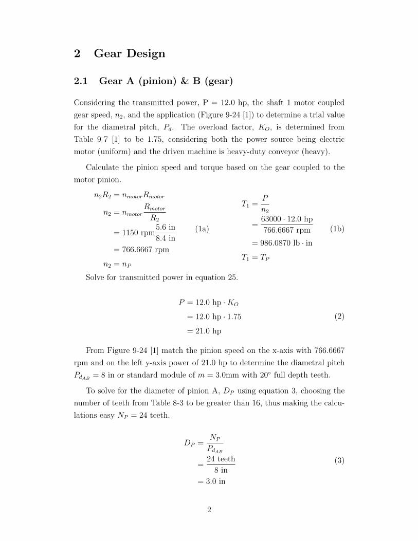
2 Gear Design
2.1 Gear A (pinion) & B (gear)
Considering the transmitted power, P = 12.0 hp, the shaft 1 motor coupled
gear speed, n2, and the application (Figure 9-24 [1]) to determine a trial value
for the diametral pitch, Pd. The overload factor, KO, is determined from
Table 9-7 [1] to be 1.75, considering both the power source being electric
motor (uniform) and the driven machine is heavy-duty conveyor (heavy).
Calculate the pinion speed and torque based on the gear coupled to the
motor pinion.
n2R2 = nmotorRmotor
n2 = nmotorRmotor
R2
= 1150 rpm5.6 in
8.4 in
= 766.6667 rpm
n2 = nP
(1a)
T1 =P
n2
=63000 · 12.0 hp
766.6667 rpm
= 986.0870 lb · in
T1 = TP
(1b)
Solve for transmitted power in equation 25.
P = 12.0 hp ·KO
= 12.0 hp · 1.75
= 21.0 hp
(2)
From Figure 9-24 [1] match the pinion speed on the x-axis with 766.6667
rpm and on the left y-axis power of 21.0 hp to determine the diametral pitch
PdAB= 8 in or standard module of m = 3.0mm with 20◦ full depth teeth.
To solve for the diameter of pinion A, DP using equation 3, choosing the
number of teeth from Table 8-3 to be greater than 16, thus making the calcu-
lations easy NP = 24 teeth.
DP =NP
PdAB
=24 teeth
8 in
= 3.0 in
(3)
2
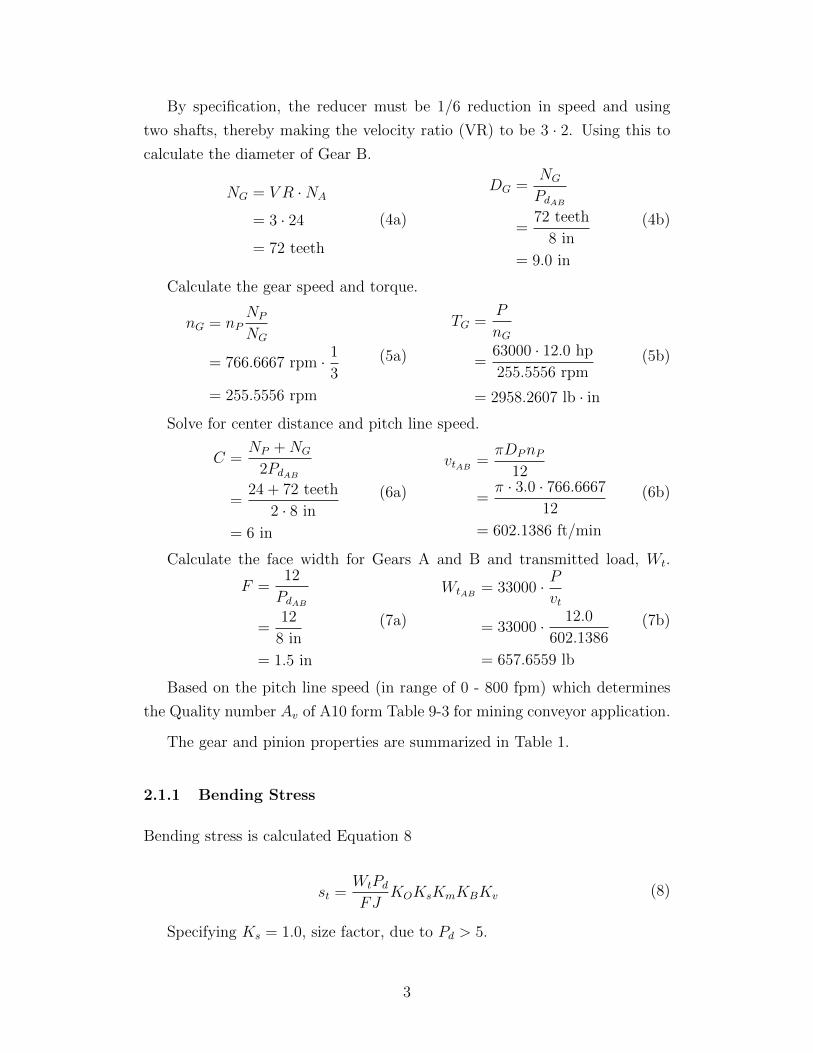
By specification, the reducer must be 1/6 reduction in speed and using
two shafts, thereby making the velocity ratio (VR) to be 3 · 2. Using this to
calculate the diameter of Gear B.
NG = V R ·NA
= 3 · 24
= 72 teeth
(4a)
DG =NG
PdAB
=72 teeth
8 in
= 9.0 in
(4b)
Calculate the gear speed and torque.
nG = nPNP
NG
= 766.6667 rpm · 1
3
= 255.5556 rpm
(5a)
TG =P
nG
=63000 · 12.0 hp
255.5556 rpm
= 2958.2607 lb · in
(5b)
Solve for center distance and pitch line speed.
C =NP +NG
2PdAB
=24 + 72 teeth
2 · 8 in
= 6 in
(6a)
vtAB=πDPnP
12
=π · 3.0 · 766.6667
12
= 602.1386 ft/min
(6b)
Calculate the face width for Gears A and B and transmitted load, Wt.
F =12
PdAB
=12
8 in
= 1.5 in
(7a)
WtAB= 33000 · P
vt
= 33000 · 12.0
602.1386
= 657.6559 lb
(7b)
Based on the pitch line speed (in range of 0 - 800 fpm) which determines
the Quality number Av of A10 form Table 9-3 for mining conveyor application.
The gear and pinion properties are summarized in Table 1.
2.1.1 Bending Stress
Bending stress is calculated Equation 8
st =WtPd
FJKOKsKmKBKv (8)
Specifying Ks = 1.0, size factor, due to Pd > 5.
3
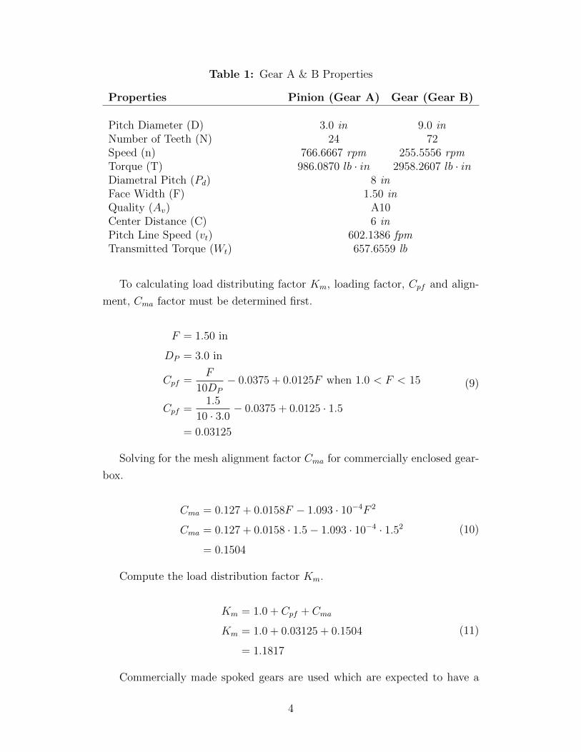
Table 1: Gear A & B Properties
Properties Pinion (Gear A) Gear (Gear B)
Pitch Diameter (D) 3.0 in 9.0 inNumber of Teeth (N) 24 72Speed (n) 766.6667 rpm 255.5556 rpmTorque (T) 986.0870 lb · in 2958.2607 lb · inDiametral Pitch (Pd) 8 inFace Width (F) 1.50 inQuality (Av) A10Center Distance (C) 6 inPitch Line Speed (vt) 602.1386 fpmTransmitted Torque (Wt) 657.6559 lb
To calculating load distributing factor Km, loading factor, Cpf and align-
ment, Cma factor must be determined first.
F = 1.50 in
DP = 3.0 in
Cpf =F
10DP
− 0.0375 + 0.0125F when 1.0 < F < 15
Cpf =1.5
10 · 3.0− 0.0375 + 0.0125 · 1.5
= 0.03125
(9)
Solving for the mesh alignment factor Cma for commercially enclosed gear-
box.
Cma = 0.127 + 0.0158F − 1.093 · 10−4F 2
Cma = 0.127 + 0.0158 · 1.5− 1.093 · 10−4 · 1.52
= 0.1504
(10)
Compute the load distribution factor Km.
Km = 1.0 + Cpf + Cma
Km = 1.0 + 0.03125 + 0.1504
= 1.1817
(11)
Commercially made spoked gears are used which are expected to have a
4
well-supported rim, thus the rim thickness factor, KB = 1.0.
Using Av = A10 determine the dynamic loading factor from Table 9-20
Kv = 1.25.
Specify the tooth form, the bending geometry factors for the pinion and
the gear from Figure 9-15 JP = 0.36, JG = 0.42.
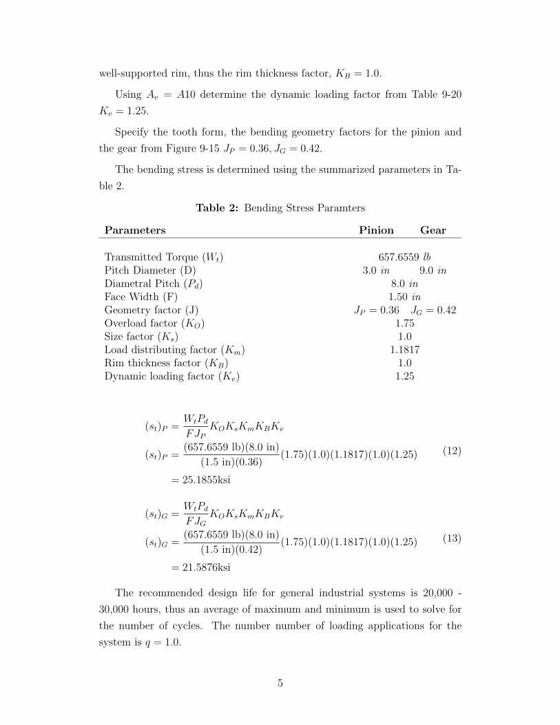
The bending stress is determined using the summarized parameters in Ta-
ble 2.
Table 2: Bending Stress Paramters
Parameters Pinion Gear
Transmitted Torque (Wt) 657.6559 lbPitch Diameter (D) 3.0 in 9.0 inDiametral Pitch (Pd) 8.0 inFace Width (F) 1.50 inGeometry factor (J) JP = 0.36 JG = 0.42Overload factor (KO) 1.75Size factor (Ks) 1.0Load distributing factor (Km) 1.1817Rim thickness factor (KB) 1.0Dynamic loading factor (Kv) 1.25
(st)P =WtPd
FJPKOKsKmKBKv
(st)P =(657.6559 lb)(8.0 in)
(1.5 in)(0.36)(1.75)(1.0)(1.1817)(1.0)(1.25)
= 25.1855ksi
(12)
(st)G =WtPd
FJGKOKsKmKBKv
(st)G =(657.6559 lb)(8.0 in)
(1.5 in)(0.42)(1.75)(1.0)(1.1817)(1.0)(1.25)
= 21.5876ksi
(13)
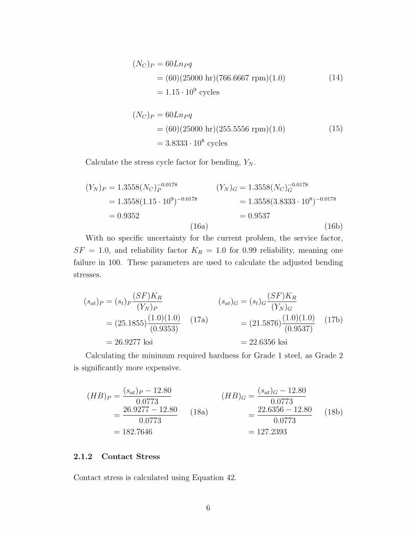
The recommended design life for general industrial systems is 20,000 -
30,000 hours, thus an average of maximum and minimum is used to solve for
the number of cycles. The number number of loading applications for the
system is q = 1.0.
5
(NC)P = 60LnP q
= (60)(25000 hr)(766.6667 rpm)(1.0)
= 1.15 · 109 cycles
(14)
(NC)P = 60LnP q
= (60)(25000 hr)(255.5556 rpm)(1.0)
= 3.8333 · 108 cycles
(15)
Calculate the stress cycle factor for bending, YN .
(YN)P = 1.3558(NC)−0.0178P
= 1.3558(1.15 · 109)−0.0178
= 0.9352
(16a)
(YN)G = 1.3558(NC)−0.0178G
= 1.3558(3.8333 · 108)−0.0178
= 0.9537
(16b)
With no specific uncertainty for the current problem, the service factor,
SF = 1.0, and reliability factor KR = 1.0 for 0.99 reliability, meaning one
failure in 100. These parameters are used to calculate the adjusted bending
stresses.
(sat)P = (st)P(SF )KR
(YN)P
= (25.1855)(1.0)(1.0)
(0.9353)
= 26.9277 ksi
(17a)
(sat)G = (st)G(SF )KR
(YN)G
= (21.5876)(1.0)(1.0)
(0.9537)
= 22.6356 ksi
(17b)
Calculating the minimum required hardness for Grade 1 steel, as Grade 2
is significantly more expensive.
(HB)P =(sat)P − 12.80
0.0773
=26.9277− 12.80
0.0773
= 182.7646
(18a)
(HB)G =(sat)G − 12.80
0.0773
=22.6356− 12.80
0.0773
= 127.2393
(18b)
2.1.2 Contact Stress
Contact stress is calculated using Equation 42.
6

sc = Cp
√Wt
FDpIKOKsKmKv (19)
The gears will be made from steel, thus the elastic coefficient, Cp = 2300.
The pitting geometry factor from Figure 9-21 I = 0.108, for 20◦pressure angle.
Solving for contact stress, using parameters stated above and in Table 2
sc = Cp
√WtAB
FDpIKOKsKmKv
sc = 2300
√657.6559 lb
(1.5 in)(3.0 in)(0.108)(1.75)(1.0)(1.1817)(1.25)
= 136.0306 ksi
(20)
Calculate the stress cycle factor, ZN using the number of cycles from Equa-
tions 14 and 15.
(ZN)P = 1.4488(NC)−0.023P
= 1.4488(1.15 · 109)−0.023
= 0.8966
(21a)
(ZN)G = 1.4488(NC)−0.023G
= 1.4488(3.8333 · 108)−0.023
= 0.9196
(21b)
The same service factor, SF = 1.0 and reliability factor KR = 1.0 are used
to calculated the adjusted contact stress.
(sac)P = sc(SF )KR
(ZN)P
= (136.0306)(1.0)(1.0)
(0.8966)
= 151.7183 ksi
(22a)
(sac)G = sc(SF )KR
(ZN)G
= (136.0306)(1.0)(1.0)
(0.9196)
= 147.9237 ksi
(22b)
Calculating the minimum required hardness for Grade 1 steel.
(HB)P =(sac)P − 29.10
0.322
=151.7183− 29.10
0.322
= 380.8022
(23a)
(HB)G =(sac)G − 29.10
0.322
=147.9237− 29.10
0.322
= 369.0177
(23b)
The HB from contact stress is approximately the same for the gear and
7
the pinion, which will constrain the material choice, along with the maximum
value of the contact stress.
Gear and the pinion will be made form SAE 1340 OQT 700 with HB =
444, Yield Strength = 197 ksi, and Tensile Strength = 221 ksi.
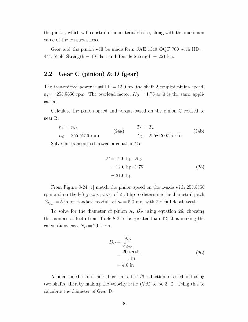
2.2 Gear C (pinion) & D (gear)
The transmitted power is still P = 12.0 hp, the shaft 2 coupled pinion speed,
nB = 255.5556 rpm. The overload factor, KO = 1.75 as it is the same appli-
cation.
Calculate the pinion speed and torque based on the pinion C related to
gear B.
nC = nB
nC = 255.5556 rpm(24a)
TC = TB
TC = 2958.2607lb · in(24b)
Solve for transmitted power in equation 25.
P = 12.0 hp ·KO
= 12.0 hp · 1.75
= 21.0 hp
(25)
From Figure 9-24 [1] match the pinion speed on the x-axis with 255.5556
rpm and on the left y-axis power of 21.0 hp to determine the diametral pitch
PdCD= 5 in or standard module of m = 5.0 mm with 20◦ full depth teeth.
To solve for the diameter of pinion A, DP using equation 26, choosing
the number of teeth from Table 8-3 to be greater than 12, thus making the
calculations easy NP = 20 teeth.
DP =NP
PdCD
=20 teeth
5 in
= 4.0 in
(26)
As mentioned before the reducer must be 1/6 reduction in speed and using
two shafts, thereby making the velocity ratio (VR) to be 3 · 2. Using this to
calculate the diameter of Gear D.
8
NG = V R ·NP
= 2 · 20
= 40 teeth
(27a)
DG =NG
PdCD
=40 teeth
5 in
= 8.0 in
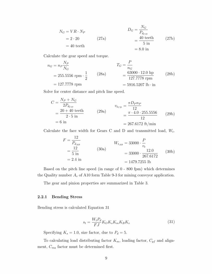
(27b)
Calculate the gear speed and torque.
nG = nPNP
NG
= 255.5556 rpm · 1
2
= 127.7778 rpm
(28a)
TG =P
nG
=63000 · 12.0 hp
127.7778 rpm
= 5916.5207 lb · in
(28b)
Solve for center distance and pitch line speed.
C =NP +NG
2PdCD
=20 + 40 teeth
2 · 5 in
= 6 in
(29a)
vtCD=πDPnP
12
=π · 4.0 · 255.5556
12
= 267.6172 ft/min
(29b)
Calculate the face width for Gears C and D and transmitted load, Wt.
F =12
PdAB
=12
5 in
= 2.4 in
(30a)
WtAB= 33000 · P
vt
= 33000 · 12.0
267.6172
= 1479.7255 lb
(30b)
Based on the pitch line speed (in range of 0 - 800 fpm) which determines
the Quality number Av of A10 form Table 9-3 for mining conveyor application.
The gear and pinion properties are summarized in Table 3.
2.2.1 Bending Stress
Bending stress is calculated Equation 31
st =WtPd
FJKOKsKmKBKv (31)
Specifying Ks = 1.0, size factor, due to Pd = 5.
To calculating load distributing factor Km, loading factor, Cpf and align-
ment, Cma factor must be determined first.
9
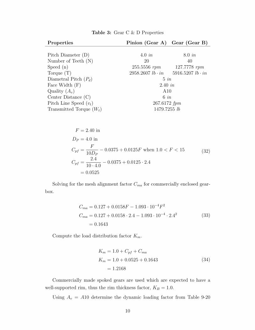
Table 3: Gear C & D Properties
Properties Pinion (Gear A) Gear (Gear B)
Pitch Diameter (D) 4.0 in 8.0 inNumber of Teeth (N) 20 40Speed (n) 255.5556 rpm 127.7778 rpmTorque (T) 2958.2607 lb · in 5916.5207 lb · inDiametral Pitch (Pd) 5 inFace Width (F) 2.40 inQuality (Av) A10Center Distance (C) 6 inPitch Line Speed (vt) 267.6172 fpmTransmitted Torque (Wt) 1479.7255 lb
F = 2.40 in
DP = 4.0 in
Cpf =F
10DP
− 0.0375 + 0.0125F when 1.0 < F < 15
Cpf =2.4
10 · 4.0− 0.0375 + 0.0125 · 2.4
= 0.0525
(32)
Solving for the mesh alignment factor Cma for commercially enclosed gear-
box.
Cma = 0.127 + 0.0158F − 1.093 · 10−4F 2
Cma = 0.127 + 0.0158 · 2.4− 1.093 · 10−4 · 2.42
= 0.1643
(33)
Compute the load distribution factor Km.
Km = 1.0 + Cpf + Cma
Km = 1.0 + 0.0525 + 0.1643
= 1.2168
(34)
Commercially made spoked gears are used which are expected to have a
well-supported rim, thus the rim thickness factor, KB = 1.0.
Using Av = A10 determine the dynamic loading factor from Table 9-20
10
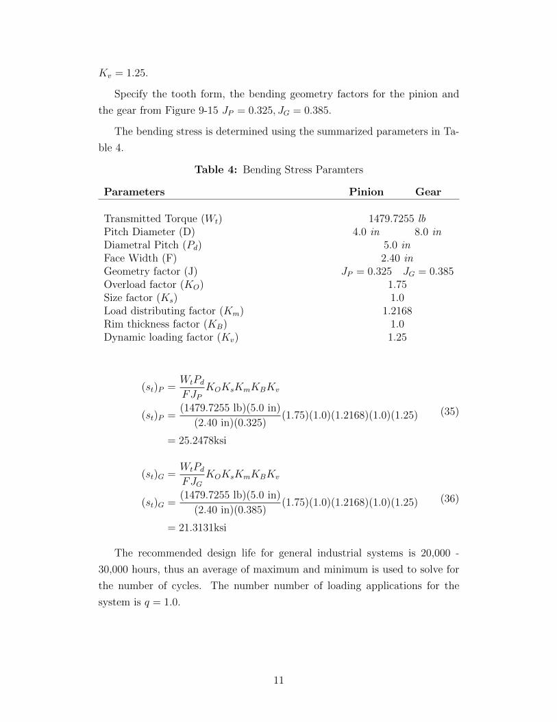
Kv = 1.25.
Specify the tooth form, the bending geometry factors for the pinion and
the gear from Figure 9-15 JP = 0.325, JG = 0.385.
The bending stress is determined using the summarized parameters in Ta-
ble 4.
Table 4: Bending Stress Paramters
Parameters Pinion Gear
Transmitted Torque (Wt) 1479.7255 lbPitch Diameter (D) 4.0 in 8.0 inDiametral Pitch (Pd) 5.0 inFace Width (F) 2.40 inGeometry factor (J) JP = 0.325 JG = 0.385Overload factor (KO) 1.75Size factor (Ks) 1.0Load distributing factor (Km) 1.2168Rim thickness factor (KB) 1.0Dynamic loading factor (Kv) 1.25
(st)P =WtPd
FJPKOKsKmKBKv
(st)P =(1479.7255 lb)(5.0 in)
(2.40 in)(0.325)(1.75)(1.0)(1.2168)(1.0)(1.25)
= 25.2478ksi
(35)
(st)G =WtPd
FJGKOKsKmKBKv
(st)G =(1479.7255 lb)(5.0 in)
(2.40 in)(0.385)(1.75)(1.0)(1.2168)(1.0)(1.25)
= 21.3131ksi
(36)
The recommended design life for general industrial systems is 20,000 -
30,000 hours, thus an average of maximum and minimum is used to solve for
the number of cycles. The number number of loading applications for the
system is q = 1.0.
11
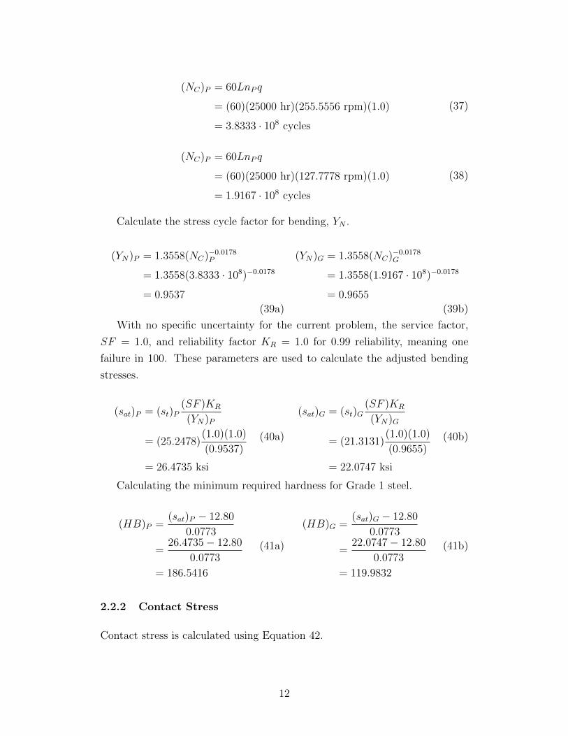
(NC)P = 60LnP q
= (60)(25000 hr)(255.5556 rpm)(1.0)
= 3.8333 · 108 cycles
(37)
(NC)P = 60LnP q
= (60)(25000 hr)(127.7778 rpm)(1.0)
= 1.9167 · 108 cycles
(38)
Calculate the stress cycle factor for bending, YN .
(YN)P = 1.3558(NC)−0.0178P
= 1.3558(3.8333 · 108)−0.0178
= 0.9537
(39a)
(YN)G = 1.3558(NC)−0.0178G
= 1.3558(1.9167 · 108)−0.0178
= 0.9655
(39b)
With no specific uncertainty for the current problem, the service factor,
SF = 1.0, and reliability factor KR = 1.0 for 0.99 reliability, meaning one
failure in 100. These parameters are used to calculate the adjusted bending
stresses.
(sat)P = (st)P(SF )KR
(YN)P
= (25.2478)(1.0)(1.0)
(0.9537)
= 26.4735 ksi
(40a)
(sat)G = (st)G(SF )KR
(YN)G
= (21.3131)(1.0)(1.0)
(0.9655)
= 22.0747 ksi
(40b)
Calculating the minimum required hardness for Grade 1 steel.
(HB)P =(sat)P − 12.80
0.0773
=26.4735− 12.80
0.0773
= 186.5416
(41a)
(HB)G =(sat)G − 12.80
0.0773
=22.0747− 12.80
0.0773
= 119.9832
(41b)
2.2.2 Contact Stress
Contact stress is calculated using Equation 42.
12
sc = Cp
√Wt
FDpIKOKsKmKv (42)
The gears will be made from steel, thus the elastic coefficient, Cp = 2300.
The pitting geometry factor from Figure 9-21 I = 0.094, for 20◦pressure angle.
Solving for contact stress, using parameters stated above and in Table 4
sc = Cp
√WtCD
FDpIKOKsKmKv
sc = 2300
√1479.7255 lb
(2.4 in)(4.0 in)(0.094)(1.75)(1.0)(1.2168)(1.25)
= 151.9506 ksi
(43)
Calculate the stress cycle factor, ZN using the number of cycles from Equa-
tions 14 and 15.
(ZN)P = 1.4488(NC)−0.023P
= 1.4488(3.8333 · 108)−0.023
= 0.9196
(44a)
(ZN)G = 1.4488(NC)−0.023G
= 1.4488(1.9167 · 108)−0.023
= 0.9344
(44b)
The same service factor, SF = 1.0 and reliability factor KR = 1.0 are used
to calculated the adjusted contact stress.
(sac)P = sc(SF )KR
(ZN)P
= (151.9506)(1.0)(1.0)
(0.9196)
= 165.2355 ksi
(45a)
(sac)G = sc(SF )KR
(ZN)G
= (151.9506)(1.0)(1.0)
(0.9344)
= 162.6184 ksi
(45b)
Calculating the minimum required hardness for Grade 1 steel.
(HB)P =(sac)P − 29.10
0.322
=165.2355− 29.10
0.322
= 422.7810
(46a)
(HB)G =(sac)G − 29.10
0.322
=162.6184− 29.10
0.322
= 414.6534
(46b)
The HB from contact stress is approximately the same for the gear and
13
the pinion, which will constrain the material choice, along with the maximum
value of the contact stress.
Gear and the pinion will be made form Cold Drawn SAE 1340 with HB =
160, Yield Strength = 71 ksi, and Tensile Strength = 80 ksi.
14
3 Shaft Design
All shafts are designed using the previously designed gears, and a safety factor
of N = 3. The shafts will be machined from cold drawn SAE 1040 steel (Table 5
for material properties from Appendix 3 [1]).
Table 5: SAE 1040 CD Steel Properties
sy (ksi) su (ksi) sn (ksi)
71 80 31
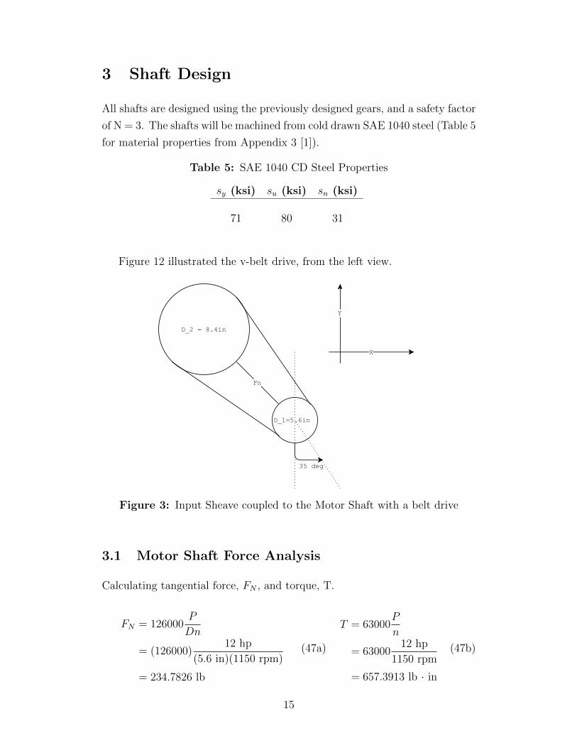
Figure 12 illustrated the v-belt drive, from the left view.
Figure 3: Input Sheave coupled to the Motor Shaft with a belt drive
3.1 Motor Shaft Force Analysis
Calculating tangential force, FN , and torque, T.
FN = 126000P
Dn
= (126000)12 hp
(5.6 in)(1150 rpm)
= 234.7826 lb
(47a)
T = 63000P
n
= 6300012 hp
1150 rpm
= 657.3913 lb · in
(47b)
15
Solve for the bending force at the sheave, FB, using the factor of 1.5 for
the v-belt sheave.
FB = 1.5FN
= 1.5(234.7826 lb)
= 352.1739 lb↖
(48)
Solve for forces in x and y directions.
FBx = FB sin 35◦
= 352.1739 sin 35◦
= 201.9987 lb←
(49a)
FBy = FB cos 35◦
= 352.1739 cos 35◦
= 288.4840 lb ↑
(49b)
3.2 Reducer Shaft (Shaft 1) Force Analysis
The torque at Gear A is calculated in equation 1b. TA = 986.0870 lb · in.
The forces for gear A on shaft 1, are equal in magnitude to the input sheave
(motor pinion) but opposite in direction.
FB = 352.1739 lb↘
FBx = 201.9987 lb→
FBy = 288.4840 lb ↓
(50)
Calculate the tangential force, WtA , and radial force, WrA for 20◦ pressure
angle, φ.
WtA =TADA
2
=986.0870
3.02
= 657.3913 lb→
(51a)WrA = WtA tanφ
= 657.3913 lb tan 20◦
= 239.2709 lb ↓
(51b)
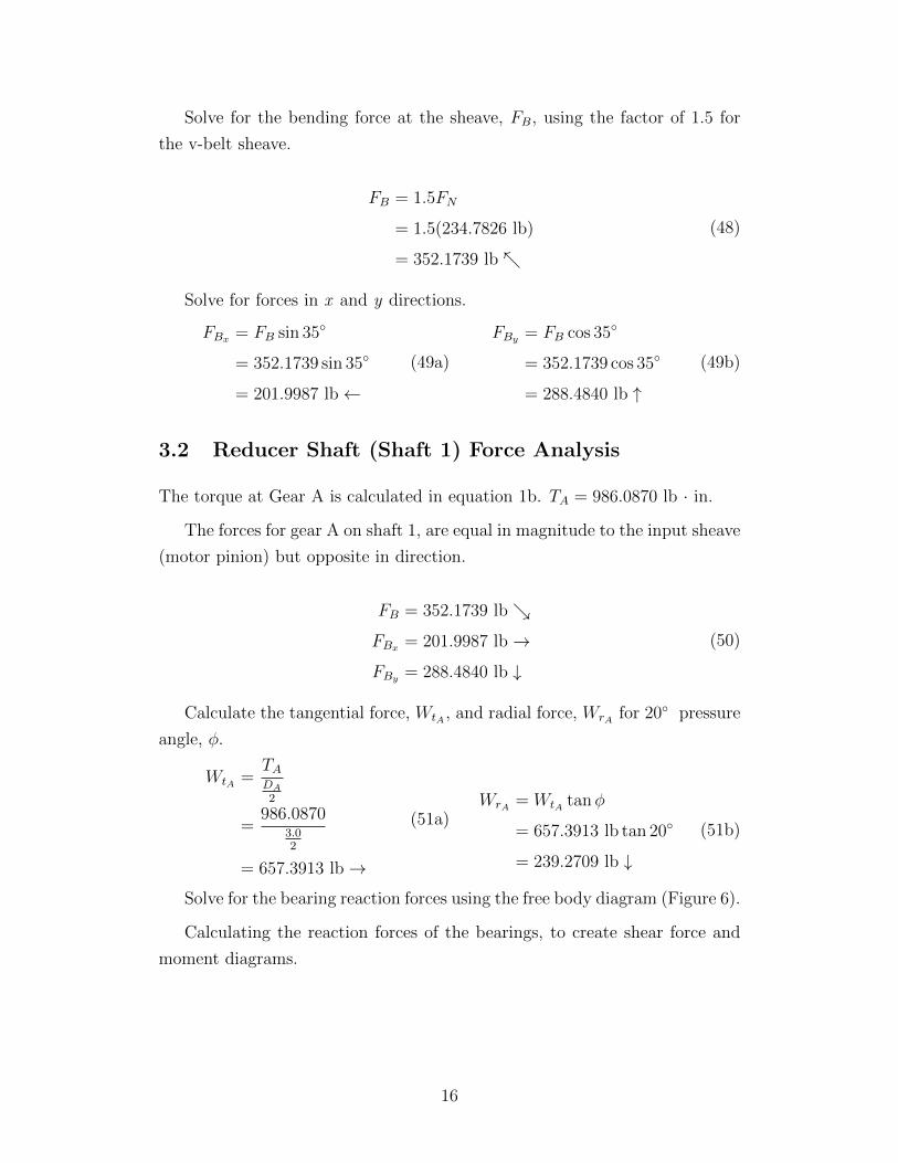
Solve for the bearing reaction forces using the free body diagram (Figure 6).
Calculating the reaction forces of the bearings, to create shear force and
moment diagrams.
16
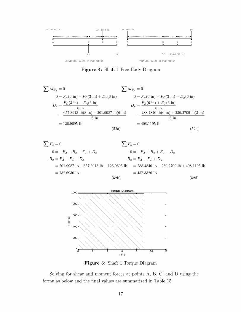
Figure 4: Shaft 1 Free Body Diagram
∑MBx = 0
0 = FA(6 in)− FC(3 in) +Dx(6 in)
Dx =FC(3 in)− FA(6 in)
6 in
=657.3913 lb(3 in)− 201.9987 lb(6 in)
6 in
= 126.9695 lb
(52a)
∑Fx = 0
0 = −FA +Bx − FC +Dx
Bx = FA + FC −Dx
= 201.9987 lb + 657.3913 lb− 126.9695 lb
= 732.6930 lb
(52b)
∑MBy = 0
0 = FA(6 in) + FC(3 in)−Dy(6 in)
Dy =FA(6 in) + FC(3 in)
6 in
=288.4840 lb(6 in) + 239.2709 lb(3 in)
6 in
= 408.1195 lb
(52c)
∑Fy = 0
0 = −FA +By + FC −Dy
By = FA − FC +Dy
= 288.4840 lb− 239.2709 lb + 408.1195 lb
= 457.3326 lb
(52d)
0 2 4 6 8 10 12z (in)
0
200
400
600
800
1000
T (
lb*i
n)
Torque Diagram
Figure 5: Shaft 1 Torque Diagram
Solving for shear and moment forces at points A, B, C, and D using the
formulas below and the final values are summarized in Table 15
17
300200100
0100200300400500600
V (
lb)
Horizontal Plane Vertical Plane
0 2 4 6 8 10 12z (in)
2000
1500
1000
500
0
500
M (
lb.in)
0 2 4 6 8 10 12z (in)
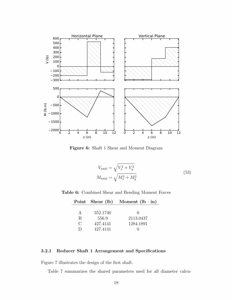
Figure 6: Shaft 1 Shear and Moment Diagram
Vtotal =√V 2x + V 2
y
Mtotal =√M2
x +M2y
(53)
Table 6: Combined Shear and Bending Moment Forces
Point Shear (lb) Moment (lb · in)
A 352.1740 0B 556.9 2113.0437C 427.4141 1284.1891D 427.4141 0
3.2.1 Reducer Shaft 1 Arrangement and Specifications
Figure 7 illustrates the design of the first shaft.
Table 7 summarizes the shared parameters used for all diameter calcu-
18
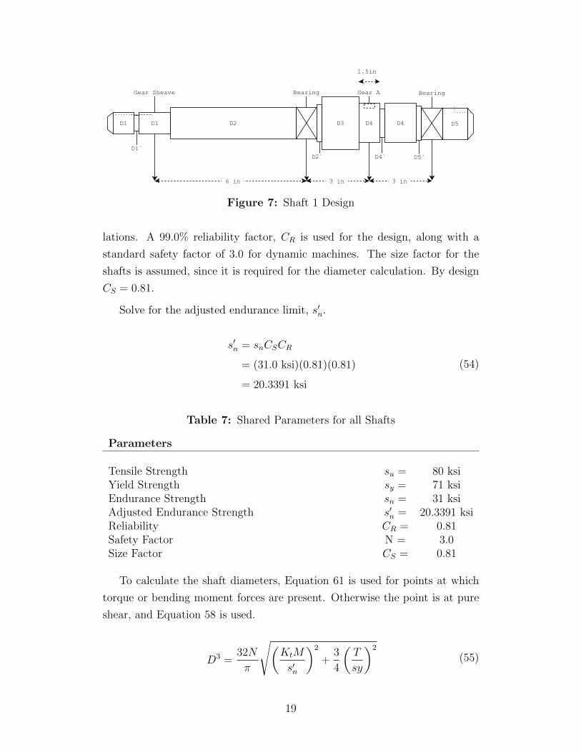
Figure 7: Shaft 1 Design
lations. A 99.0% reliability factor, CR is used for the design, along with a
standard safety factor of 3.0 for dynamic machines. The size factor for the
shafts is assumed, since it is required for the diameter calculation. By design
CS = 0.81.
Solve for the adjusted endurance limit, s′n.
s′n = snCSCR
= (31.0 ksi)(0.81)(0.81)
= 20.3391 ksi
(54)
Table 7: Shared Parameters for all Shafts
Parameters
Tensile Strength su = 80 ksiYield Strength sy = 71 ksiEndurance Strength sn = 31 ksiAdjusted Endurance Strength s′n = 20.3391 ksiReliability CR = 0.81Safety Factor N = 3.0Size Factor CS = 0.81
To calculate the shaft diameters, Equation 61 is used for points at which
torque or bending moment forces are present. Otherwise the point is at pure
shear, and Equation 58 is used.
D3 =32N
π
√(KtM
s′n
)2
+3
4
(T
sy
)2
(55)
19
D =
√2.94KtV N
s′n(56)
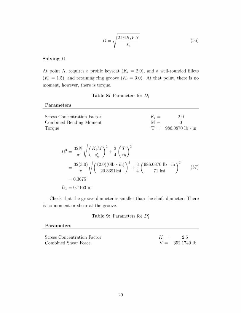
Solving D1
At point A, requires a profile keyseat (Kt = 2.0), and a well-rounded fillets
(Kt = 1.5), and retaining ring groove (Kt = 3.0). At that point, there is no
moment, however, there is torque.
Table 8: Parameters for D1
Parameters
Stress Concentration Factor Kt = 2.0Combined Bending Moment M = 0Torque T = 986.0870 lb · in
D31 =
32N
π
√(KtM
s′n
)2
+3
4
(T
sy
)2
=32(3.0)
π
√((2.0)(0lb · in)
20.3391ksi
)2
+3
4
(986.0870 lb · in
71 ksi
)2
= 0.3675
D1 = 0.7163 in
(57)
Check that the groove diameter is smaller than the shaft diameter. There
is no moment or shear at the groove.
Table 9: Parameters for D′1
Parameters
Stress Concentration Factor Kt = 2.5Combined Shear Force V = 352.1740 lb
20
D′1 =
√2.94KtV N
s′n
=
√2.94(3.0)(352.1740 lb)(3.0)
20.3391ksi
= 0.6769 in
(58)
Set D′1 = D1 = 0.7163. The preferred size for D′1 = 0.75, thus D1 =
1.06 ∗D′1 = 0.7950. The preferred size for D1 = 0.8000 in.
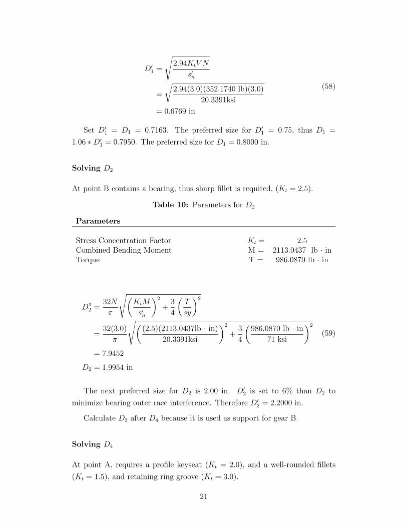
Solving D2
At point B contains a bearing, thus sharp fillet is required, (Kt = 2.5).
Table 10: Parameters for D2
Parameters
Stress Concentration Factor Kt = 2.5Combined Bending Moment M = 2113.0437 lb · inTorque T = 986.0870 lb · in
D32 =
32N
π
√(KtM
s′n
)2
+3
4
(T
sy
)2
=32(3.0)
π
√((2.5)(2113.0437lb · in)
20.3391ksi
)2
+3
4
(986.0870 lb · in
71 ksi
)2
= 7.9452
D2 = 1.9954 in
(59)
The next preferred size for D2 is 2.00 in. D′2 is set to 6% than D2 to
minimize bearing outer race interference. Therefore D′2 = 2.2000 in.
Calculate D3 after D4 because it is used as support for gear B.
Solving D4
At point A, requires a profile keyseat (Kt = 2.0), and a well-rounded fillets
(Kt = 1.5), and retaining ring groove (Kt = 3.0).
21
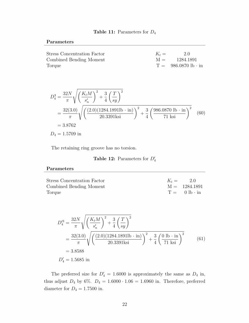
Table 11: Parameters for D4
Parameters
Stress Concentration Factor Kt = 2.0Combined Bending Moment M = 1284.1891Torque T = 986.0870 lb · in
D34 =
32N
π
√(KtM
s′n
)2
+3
4
(T
sy
)2
=32(3.0)
π
√((2.0)(1284.1891lb · in)
20.3391ksi
)2
+3
4
(986.0870 lb · in
71 ksi
)2
= 3.8762
D4 = 1.5709 in
(60)
The retaining ring groove has no torsion.
Table 12: Parameters for D′4
Parameters
Stress Concentration Factor Kt = 2.0Combined Bending Moment M = 1284.1891Torque T = 0 lb · in
D′34 =32N
π
√(KtM
s′n
)2
+3
4
(T
sy
)2
=32(3.0)
π
√((2.0)(1284.1891lb · in)
20.3391ksi
)2
+3
4
(0 lb · in
71 ksi
)2
= 3.8588
D′4 = 1.5685 in
(61)
The preferred size for D′4 = 1.6000 is approximately the same as D4 in,
thus adjust D4 by 6%. D4 = 1.6000 · 1.06 = 1.6960 in. Therefore, preferred
diameter for D4 = 1.7500 in.
22

Solving D3
The D3 has to be bigger than D4 to retain it on one side. Therefore, make D3 =
1.15D4 = 2.0125 in. Thus the preferred size for D3 = 2.2000 in. However,
D′2 = D3 therefore D3 must be increased further. New D3 = 2.5000 in.
Solving D5
At point D contains a bearing, thus sharp fillet is required, (Kt = 2.5).
Table 13: Parameters for D5
Parameters
Stress Concentration Factor Kt = 3.0Combined Shear Force V = 427.4141 lb
D5 =
√2.94KtV N
s′n
=
√2.94(3.0)(427.4141 lb)(3.0)
20.3391ksi
= 0.7457 in
(62)
The next preferred size is 0.7500 in. D′5 is set to 15% than D5 to minimize
bearing outer race interference. Therefore D′5 = 0.8625 = 1.0000 in.
Summary
Table 30 displays all the diameters for Shaft 1. It is assumed that the bearings
for standard size diameters are available. Based on the choice of bearings may
require change in D’ diameters to prevent interference with the outer rase of
the bearing. None of the diameters exceed 2.5 in which was the assumption
for CS = 0.81.
3.3 Reducer Middle Shaft (Shaft 2) Force Analysis
The torque at Gear B is calculated in equation 5b. TB = 2958.2607 lb · in.
23
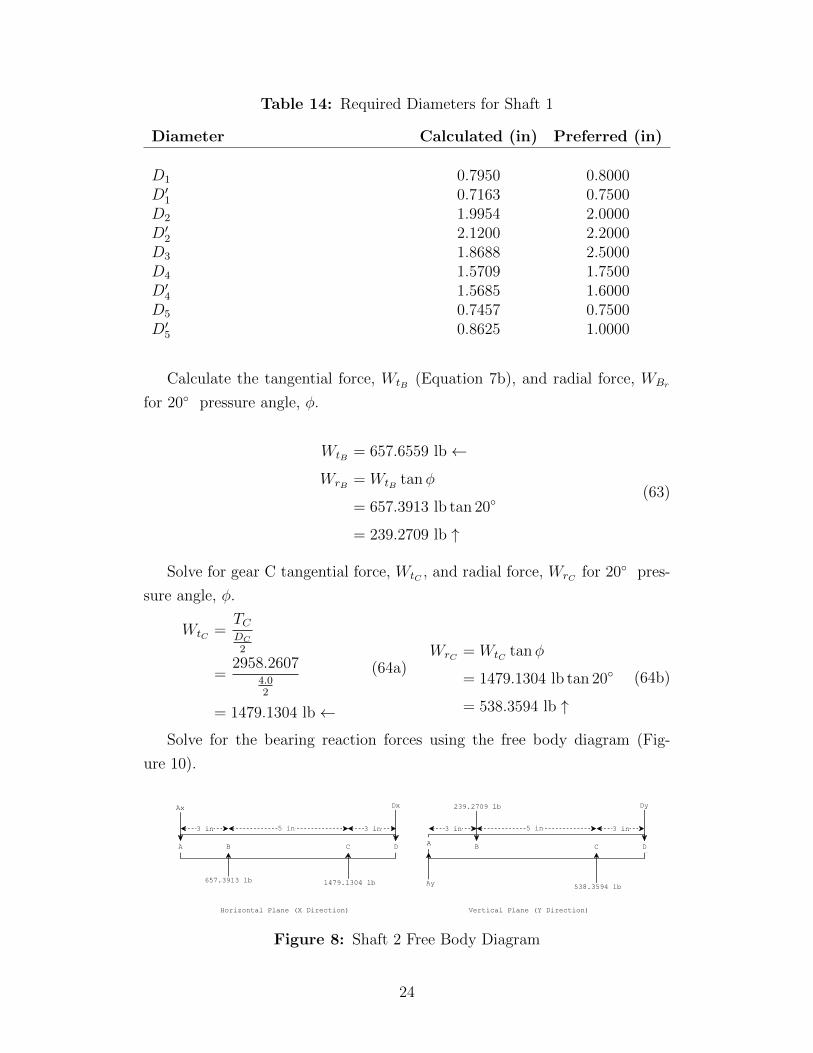
Table 14: Required Diameters for Shaft 1
Diameter Calculated (in) Preferred (in)
D1 0.7950 0.8000D′1 0.7163 0.7500D2 1.9954 2.0000D′2 2.1200 2.2000D3 1.8688 2.5000D4 1.5709 1.7500D′4 1.5685 1.6000D5 0.7457 0.7500D′5 0.8625 1.0000
Calculate the tangential force, WtB (Equation 7b), and radial force, WBr
for 20◦ pressure angle, φ.
WtB = 657.6559 lb←
WrB = WtB tanφ
= 657.3913 lb tan 20◦
= 239.2709 lb ↑
(63)
Solve for gear C tangential force, WtC , and radial force, WrC for 20◦ pres-
sure angle, φ.
WtC =TCDC
2
=2958.2607
4.02
= 1479.1304 lb←
(64a)WrC = WtC tanφ
= 1479.1304 lb tan 20◦
= 538.3594 lb ↑
(64b)
Solve for the bearing reaction forces using the free body diagram (Fig-
ure 10).
Figure 8: Shaft 2 Free Body Diagram
24
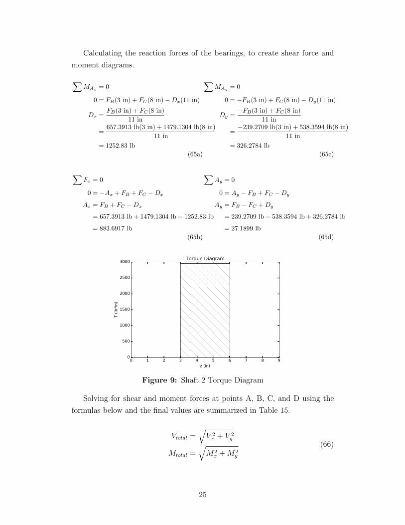
Calculating the reaction forces of the bearings, to create shear force and
moment diagrams.
∑MAx
= 0
0 = FB(3 in) + FC(8 in)−Dx(11 in)
Dx =FB(3 in) + FC(8 in)
11 in
=657.3913 lb(3 in) + 1479.1304 lb(8 in)
11 in
= 1252.83 lb
(65a)
∑Fx = 0
0 = −Ax + FB + FC −Dx
Ax = FB + FC −Dx
= 657.3913 lb + 1479.1304 lb− 1252.83 lb
= 883.6917 lb
(65b)
∑MAy
= 0
0 = −FB(3 in) + FC(8 in)−Dy(11 in)
Dy =−FB(3 in) + FC(8 in)
11 in
=−239.2709 lb(3 in) + 538.3594 lb(8 in)
11 in
= 326.2784 lb
(65c)
∑Ay = 0
0 = Ay − FB + FC −Dy
Ay = FB − FC +Dy
= 239.2709 lb− 538.3594 lb + 326.2784 lb
= 27.1899 lb
(65d)
0 1 2 3 4 5 6 7 8 9z (in)
0
500
1000
1500
2000
2500
3000
T (
lb*i
n)
Torque Diagram
Figure 9: Shaft 2 Torque Diagram
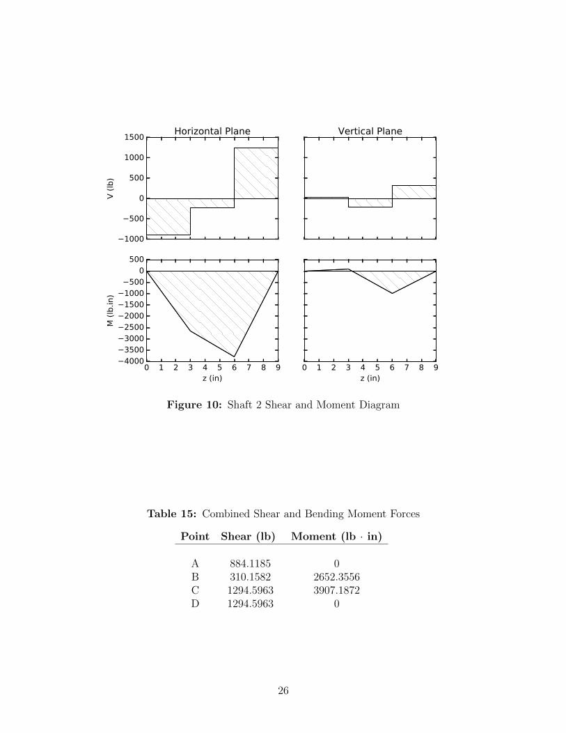
Solving for shear and moment forces at points A, B, C, and D using the
formulas below and the final values are summarized in Table 15.
Vtotal =√V 2x + V 2
y
Mtotal =√M2
x +M2y
(66)
25
1000
500
0
500
1000
1500
V (
lb)
Horizontal Plane Vertical Plane
0 1 2 3 4 5 6 7 8 9z (in)
4000350030002500200015001000
5000
500
M (
lb.in)
0 1 2 3 4 5 6 7 8 9z (in)
Figure 10: Shaft 2 Shear and Moment Diagram
Table 15: Combined Shear and Bending Moment Forces
Point Shear (lb) Moment (lb · in)
A 884.1185 0B 310.1582 2652.3556C 1294.5963 3907.1872D 1294.5963 0
26
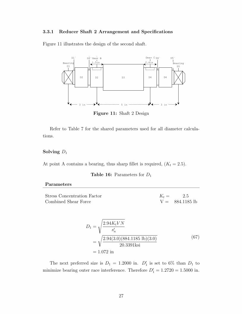
3.3.1 Reducer Shaft 2 Arrangement and Specifications
Figure 11 illustrates the design of the second shaft.
Figure 11: Shaft 2 Design
Refer to Table 7 for the shared parameters used for all diameter calcula-
tions.
Solving D1
At point A contains a bearing, thus sharp fillet is required, (Kt = 2.5).
Table 16: Parameters for D1
Parameters
Stress Concentration Factor Kt = 2.5Combined Shear Force V = 884.1185 lb
D1 =
√2.94KtV N
s′n
=
√2.94(3.0)(884.1185 lb)(3.0)
20.3391ksi
= 1.072 in
(67)
The next preferred size is D1 = 1.2000 in. D′1 is set to 6% than D1 to
minimize bearing outer race interference. Therefore D′1 = 1.2720 = 1.5000 in.
27
Solving D2
At point B, requires a profile keyseat (Kt = 2.0), and a well-rounded fillets
(Kt = 1.5), and retaining ring groove (Kt = 3.0).
Table 17: Parameters for D2
Parameters
Stress Concentration Factor Kt = 2.0Combined Bending Moment M = 2652.3556Torque T = 2958.2607 lb · in
D32 =
32N
π
√(KtM
s′n
)2
+3
4
(T
sy
)2
=32(3.0)
π
√((2.0)(2652.3556lb · in)
20.3391ksi
)2
+3
4
(2958.2607 lb · in
71 ksi
)2
= 8.0458
D2 = 2.0038 in
(68)
Check that the groove diameter is smaller than the shaft diameter. There
is no moment or shear at the groove.
Table 18: Parameters for D′2
Parameters
Stress Concentration Factor Kt = 2.0Combined Bending Moment M = 2652.3556Torque T = 0 lb · in
D′32 =32N
π
√(KtM
s′n
)2
+3
4
(T
sy
)2
=32(3.0)
π
√((2.0)(2652.3556lb · in)
20.3391ksi
)2
+3
4
(0 lb · in
71 ksi
)2
= 7.9699
D′2 = 1.9975 in
(69)
28
D′2 is set to D2 because the two diameters are approximately the same.
The preferred size for D′2 = 2.2000. D2 = 1.06D′2 = 2.3320 = 2.4000 in.
Solving D3
The D3 has to be bigger than D2 to retain it on one side. Therefore, make
D3 = 1.15D2 = 2.7600 in. Thus the preferred size for D3 = 2.8000 in.
Solving D4
At point C, requires a profile keyseat (Kt = 2.0), and a well-rounded fillets
(Kt = 1.5), and retaining ring groove (Kt = 3.0).
Table 19: Parameters for D4
Parameters
Stress Concentration Factor Kt = 2.0Combined Bending Moment M = 3907.1872Torque T = 2958.2607 lb · in
D34 =
32N
π
√(KtM
s′n
)2
+3
4
(T
sy
)2
=32(3.0)
π
√((2.0)(3907.1872lb · in)
20.3391ksi
)2
+3
4
(2958.2607 lb · in
71 ksi
)2
= 11.7921
D4 = 2.2761 in
(70)
Check that the groove diameter is smaller than the shaft diameter. There
is no moment or shear at the groove.
Table 20: Parameters for D′4
Parameters
Stress Concentration Factor Kt = 2.0Combined Bending Moment M = 3907.1872Torque T = 0 lb · in
29
D′34 =32N
π
√(KtM
s′n
)2
+3
4
(T
sy
)2
=32(3.0)
π
√((2.0)(3907.1872lb · in)
20.3391ksi
)2
+3
4
(0 lb · in
71 ksi
)2
= 11.7404
D′4 = 2.2728 in
(71)
D′4 is set to D4 because the two diameters are approximately the same.
The preferred size for D′4 = 2.4000. D4 = 1.06D′4 = 2.544 = 2.6000 in.
Solving D5
At point D contains a bearing, thus sharp fillet is required, (Kt = 2.5).
Table 21: Parameters for D5
Parameters
Stress Concentration Factor Kt = 2.5Combined Shear Force V = 1294.5963 lb
D5 =
√2.94KtV N
s′n
=
√2.94(3.0)(1294.5963 lb)(3.0)
20.3391ksi
= 1.2978 in
(72)
The next preferred size is D5 = 1.4000 in. D′5 is set to 6% than D5 to
minimize bearing outer race interference. Therefore D′5 = 1.4840 = 1.5000 in.
Change D1 = 1.4000 in to match D5.
Summary
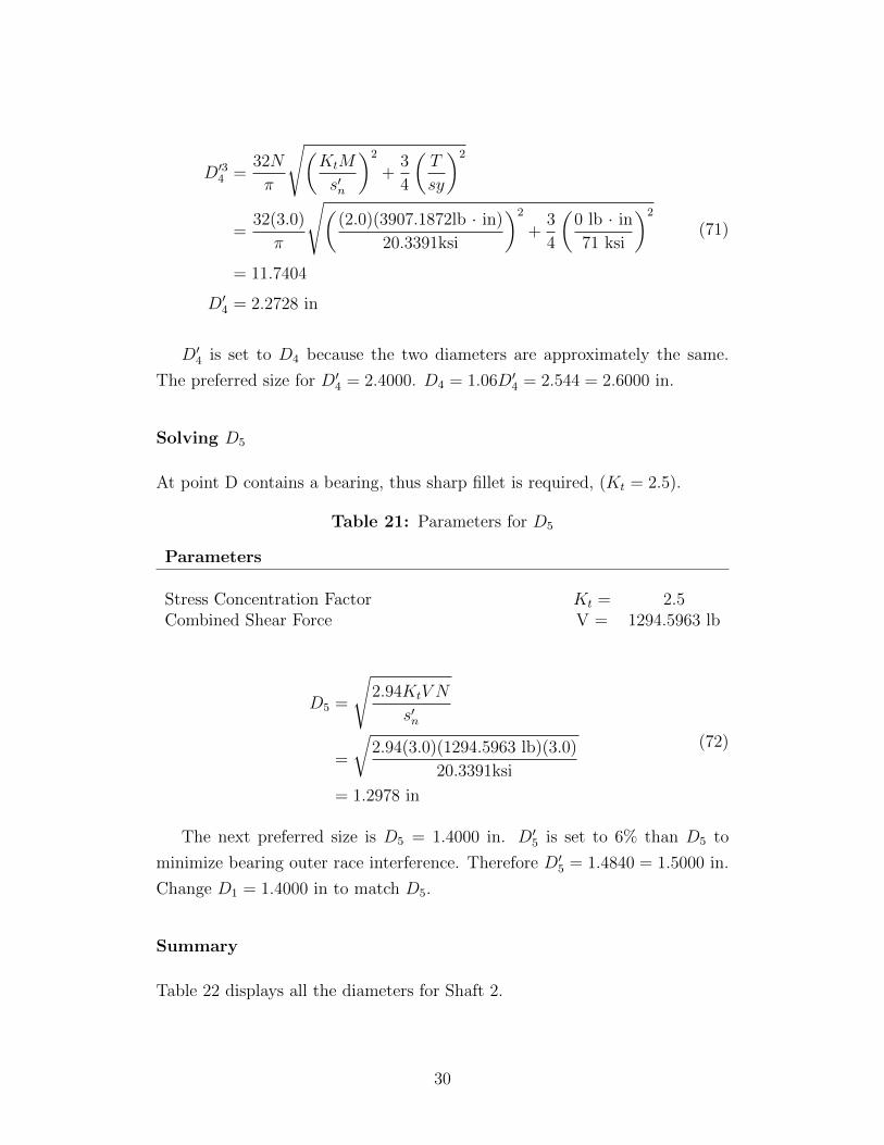
Table 22 displays all the diameters for Shaft 2.
30
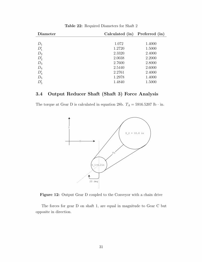
Table 22: Required Diameters for Shaft 2
Diameter Calculated (in) Preferred (in)
D1 1.072 1.4000D′1 1.2720 1.5000D2 2.3320 2.4000D′2 2.0038 2.2000D3 2.7600 2.8000D4 2.5440 2.6000D′4 2.2761 2.4000D5 1.2978 1.4000D′5 1.4840 1.5000
3.4 Output Reducer Shaft (Shaft 3) Force Analysis
The torque at Gear D is calculated in equation 28b. TA = 5916.5207 lb · in.
Figure 12: Output Gear D coupled to the Conveyor with a chain drive
The forces for gear D on shaft 1, are equal in magnitude to Gear C but
opposite in direction.
31
WtD = 1479.1304 lb→
WrD = WtD tanφ
= 1479.1304 lb tan 20◦
= 538.3594 lb ↓
(73)
Forces at the sprocket is calculated.
FN = FB
=TD
Dconveyorsprocket
2
=5916.5207 lb · in
4.2 in2
= 2817.3908 lb↗
FBx = FB sin 20◦
= 2817.3908 sin 20◦
= 963.6044 lb→
FBy = 2817.3908 cos 20◦
= 2647.4813 lb ↑
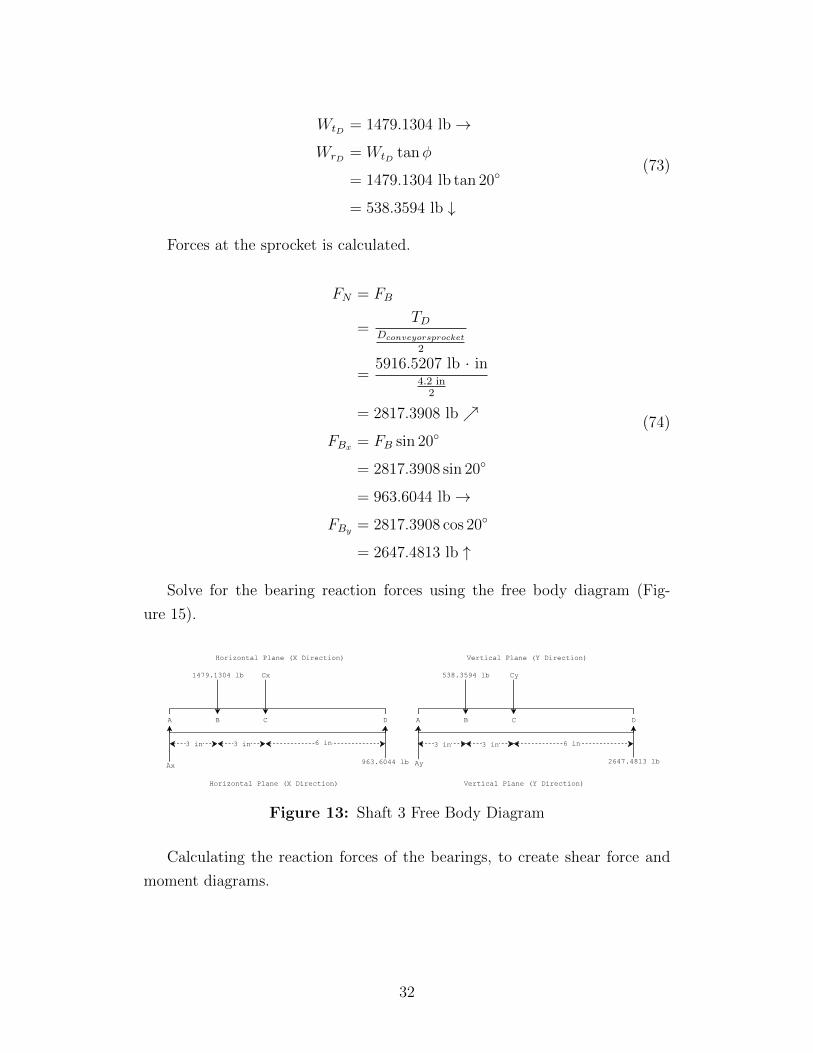
(74)
Solve for the bearing reaction forces using the free body diagram (Fig-
ure 15).
Figure 13: Shaft 3 Free Body Diagram
Calculating the reaction forces of the bearings, to create shear force and
moment diagrams.
32
∑MAx
= 0
0 = −FB(3 in)− Cx(6 in) + FD(12 in)
Cx =−1479.1304(3 in) + 963.6044(12 in)
6 in
= 1187.6436 lb
(75a)
∑Fx = 0
0 = Ax − FB − Cx + FD
Ax = FB + Cx − FD
= 1479.1304lb + 1187.6436lb− 963.6044lb
= 1703.1696 lb
(75b)
∑MAy = 0
0 = −FB(3 in)− Cy(6 in) + FD(12 in)
Cy =−FB(3 in) + FD(12 in)
6 in
=−538.3594(3 in) + 2647.4813(12 in)
6 in
= 5025.7829 lb
(75c)
∑Fy = 0
0 = Ay − FB − Cy + FD
Ay = FB + Cy − FD
= 538.3594 lb + 5025.7829 lb− 2647.4813 lb
= 2916.661 lb
(75d)
0 2 4 6 8 10 12z (in)
0
1000
2000
3000
4000
5000
6000
T (
lb*i
n)
Torque Diagram
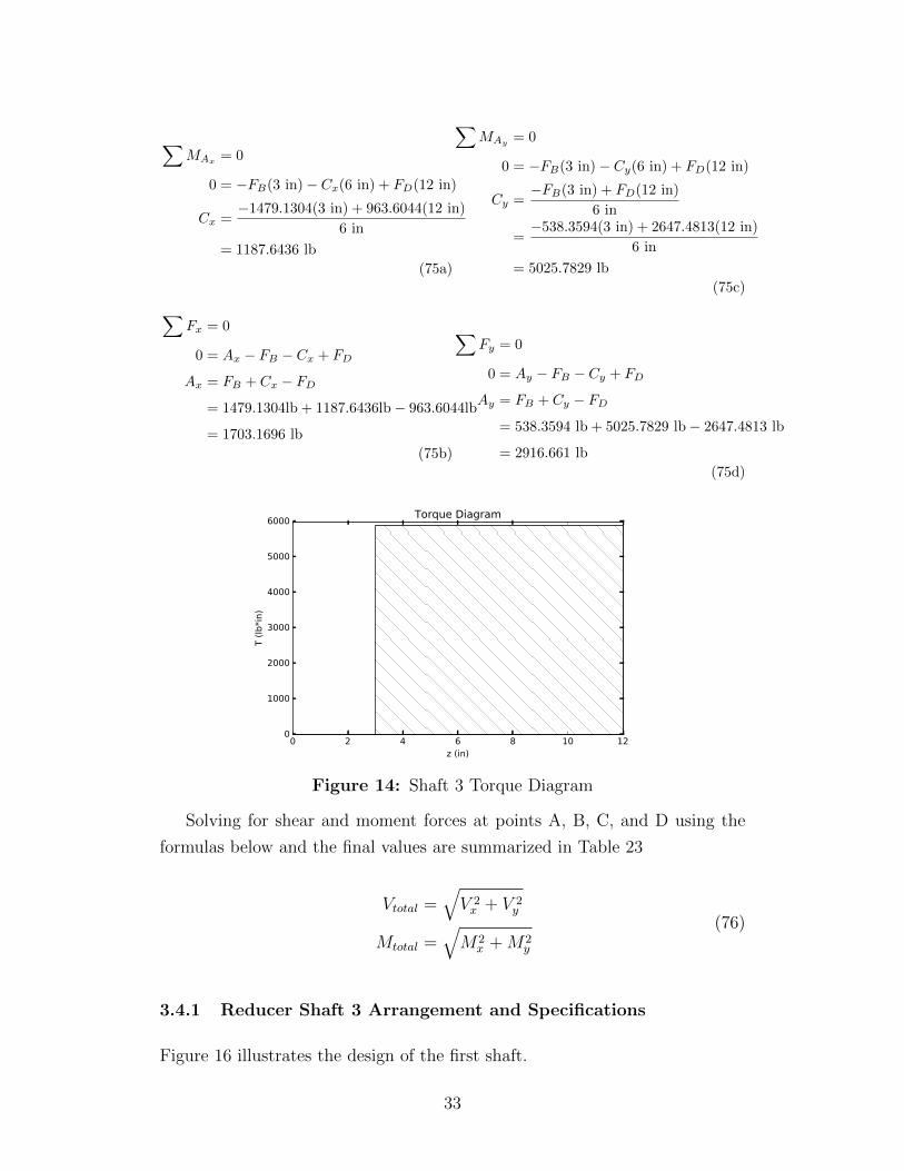
Figure 14: Shaft 3 Torque Diagram
Solving for shear and moment forces at points A, B, C, and D using the
formulas below and the final values are summarized in Table 23
Vtotal =√V 2x + V 2
y
Mtotal =√M2
x +M2y
(76)
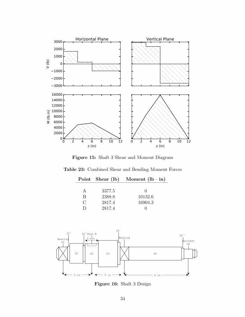
3.4.1 Reducer Shaft 3 Arrangement and Specifications
Figure 16 illustrates the design of the first shaft.
33
3000
2000
1000
0
1000
2000
3000
V (
lb)
Horizontal Plane Vertical Plane
0 2 4 6 8 10 12z (in)
0
2000
4000
6000
8000
10000
12000
14000
16000
M (
lb.in)
0 2 4 6 8 10 12z (in)
Figure 15: Shaft 3 Shear and Moment Diagram
Table 23: Combined Shear and Bending Moment Forces
Point Shear (lb) Moment (lb · in)
A 3377.5 0B 2388.8 10132.6C 2817.4 16904.3D 2817.4 0
Figure 16: Shaft 3 Design
34
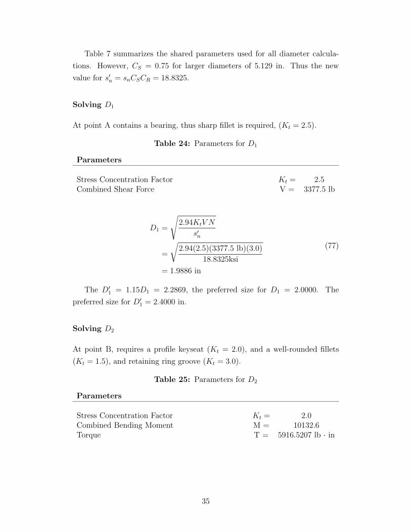
Table 7 summarizes the shared parameters used for all diameter calcula-
tions. However, CS = 0.75 for larger diameters of 5.129 in. Thus the new
value for s′n = snCSCR = 18.8325.
Solving D1
At point A contains a bearing, thus sharp fillet is required, (Kt = 2.5).
Table 24: Parameters for D1
Parameters
Stress Concentration Factor Kt = 2.5Combined Shear Force V = 3377.5 lb
D1 =
√2.94KtV N
s′n
=
√2.94(2.5)(3377.5 lb)(3.0)
18.8325ksi
= 1.9886 in
(77)
The D′1 = 1.15D1 = 2.2869, the preferred size for D1 = 2.0000. The
preferred size for D′1 = 2.4000 in.
Solving D2
At point B, requires a profile keyseat (Kt = 2.0), and a well-rounded fillets
(Kt = 1.5), and retaining ring groove (Kt = 3.0).
Table 25: Parameters for D2
Parameters
Stress Concentration Factor Kt = 2.0Combined Bending Moment M = 10132.6Torque T = 5916.5207 lb · in
35
D32 =
32N
π
√(KtM
s′n
)2
+3
4
(T
sy
)2
=32(3.0)
π
√((2.0)(10132.6lb · in)
18.8325ksi
)2
+3
4
(5916.5207 lb · in
71 ksi
)2
= 32.9563
D2 = 3.2061 in
(78)
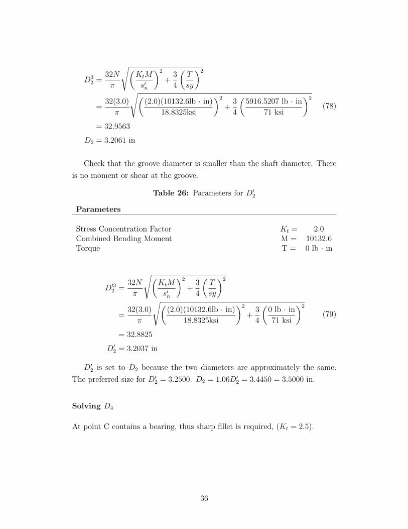
Check that the groove diameter is smaller than the shaft diameter. There
is no moment or shear at the groove.
Table 26: Parameters for D′2
Parameters
Stress Concentration Factor Kt = 2.0Combined Bending Moment M = 10132.6Torque T = 0 lb · in
D′32 =32N
π
√(KtM
s′n
)2
+3
4
(T
sy
)2
=32(3.0)
π
√((2.0)(10132.6lb · in)
18.8325ksi
)2
+3
4
(0 lb · in
71 ksi
)2
= 32.8825
D′2 = 3.2037 in
(79)
D′2 is set to D2 because the two diameters are approximately the same.
The preferred size for D′2 = 3.2500. D2 = 1.06D′2 = 3.4450 = 3.5000 in.
Solving D4
At point C contains a bearing, thus sharp fillet is required, (Kt = 2.5).
36
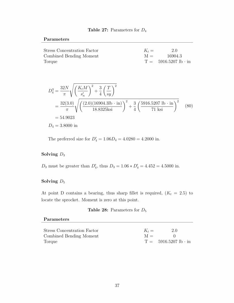
Table 27: Parameters for D4
Parameters
Stress Concentration Factor Kt = 2.0Combined Bending Moment M = 16904.3Torque T = 5916.5207 lb · in
D34 =
32N
π
√(KtM
s′n
)2
+3
4
(T
sy
)2
=32(3.0)
π
√((2.0)(16904.3lb · in)
18.8325ksi
)2
+3
4
(5916.5207 lb · in
71 ksi
)2
= 54.9023
D4 = 3.8000 in
(80)
The preferred size for D′4 = 1.06D4 = 4.0280 = 4.2000 in.
Solving D3
D3 must be greater than D′4, thus D3 = 1.06 ∗D′4 = 4.452 = 4.5000 in.
Solving D5
At point D contains a bearing, thus sharp fillet is required, (Kt = 2.5) to
locate the sprocket. Moment is zero at this point.
Table 28: Parameters for D5
Parameters
Stress Concentration Factor Kt = 2.0Combined Bending Moment M = 0Torque T = 5916.5207 lb · in
37

D35 =
32N
π
√(KtM
s′n
)2
+3
4
(T
sy
)2
=32(3.0)
π
√((2.0)(0lb · in)
18.8325ksi
)2
+3
4
(5916.5207 lb · in
71 ksi
)2
= 2.2053
D5 = 1.3016 in
(81)
solve for the groove, Kt = 3.0.
Table 29: Parameters for D′5
Parameters
Stress Concentration Factor Kt = 2.5Combined Shear Force V = 2817.4 lb
D′5 =
√2.94KtV N
s′n
=
√2.94(3.0)(2817.4 lb)(3.0)
18.8325ksi
= 1.9886 in
(82)
D5 must be greater than D′5, the preferred size for D′5 = 2.0000. D5 =
1.06 ∗ D′5 = 2.1200 = 2.2000 in. D′′5 must be greater than D5, thus D′′5 =
1.15 ∗D5 = 2.5300 = 2.6000 in.
Summary
Table 30 displays all the diameters for Shaft 1. It is assumed that the bearings
for standard size diameters are available. Based on the choice of bearings may
require change in D’ diameters to prevent interference with the outer rase of
the bearing. None of the diameters exceed 2.5 in which was the assumption
for CS = 0.81.
38
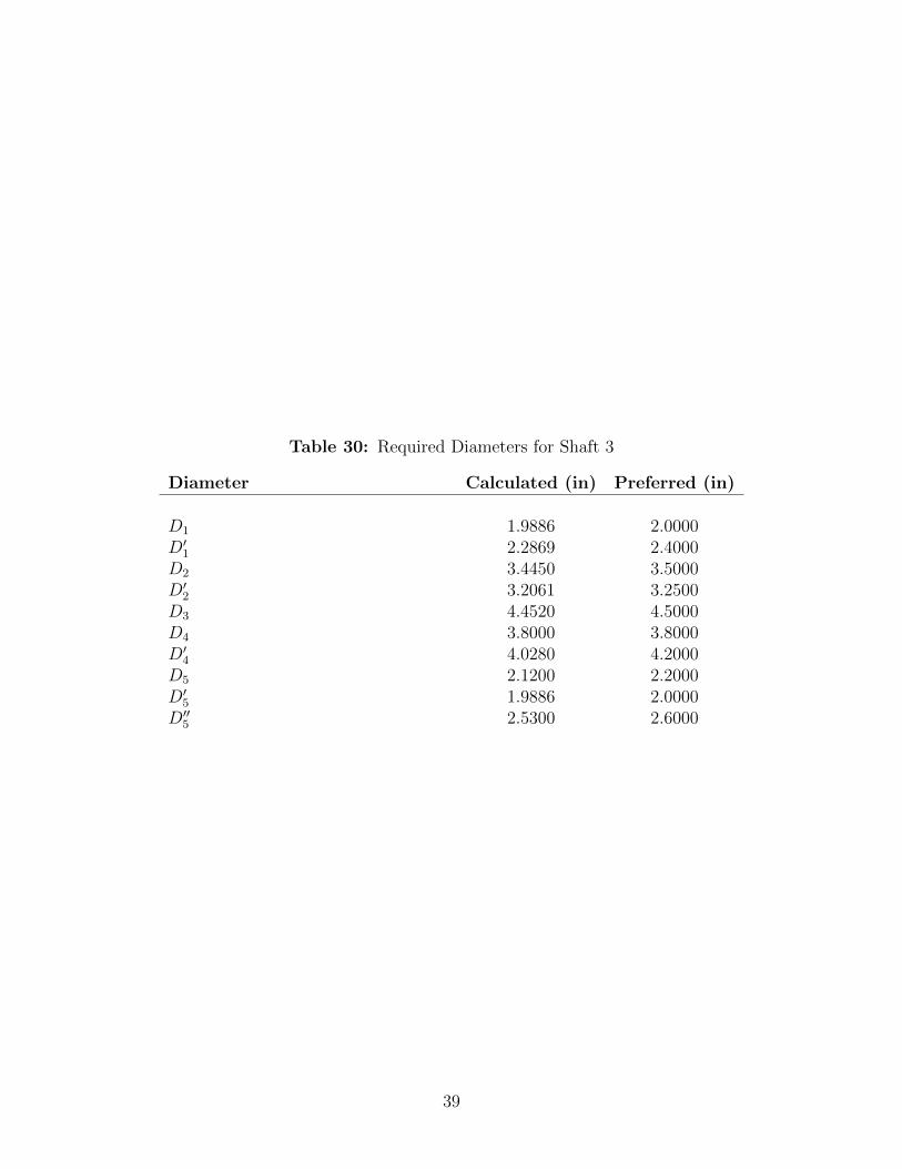
Table 30: Required Diameters for Shaft 3
Diameter Calculated (in) Preferred (in)
D1 1.9886 2.0000D′1 2.2869 2.4000D2 3.4450 3.5000D′2 3.2061 3.2500D3 4.4520 4.5000D4 3.8000 3.8000D′4 4.0280 4.2000D5 2.1200 2.2000D′5 1.9886 2.0000D′′5 2.5300 2.6000
39
4 Conclusion
In conclusion, SAE 1040 cold-drawn steel is used for the shafts, SAE 1340
OQT 700 steel for gears A & B, and cold-drawn SAE 1340 steel for gears C &
D. The dimensions of the gears are summarizes at the end of each gear pair
design, and dimensions of the shaft are at the end of each shaft design section.
40
5 References
[1] P. Robert L. Mott, Machine Elements in Mechanical Design. Pearson,2014.
41