Embed Size (px)
Citation preview

1 VK_2052753GB / 12/2005 • Subject to technical modifications
GEA Power Geko
DATA & FACTS
Air Treatment Division
GEA Power GekoFan coil unit for an air of hospitality

2 VK_2052753GB / 12/2005 • Subject to technical modifications
GEA Power Geko
Content Page
Sizes .......................................................................................................................................................................... 1.2Components of the fan coil units .............................................................................................................................. 2Unit selection ............................................................................................................................................................... 3Description of the unit ................................................................................................................................................ 4Component description .............................................................................................................................................. 6Coil pressure drops for warm and chilled water ..................................................................................................... 22Example of capacity determination .......................................................................................................................... 23Capacity overview for different external pressures................................................................................................ 24Acoustics ................................................................................................................................................................... 30Sound pressure level, sound power level .............................................................................................................. 33NR and NC limiting curves ....................................................................................................................................... 34Unit selection and flow rate determination.............................................................................................................. 35Characteristic curves for flow rate determination .................................................................................................. 36Installation examples ................................................................................................................................................. 37Dimensions for basic units ....................................................................................................................................... 38Accessory dimensions ............................................................................................................................................. 40Control behaviour of valves ..................................................................................................................................... 42Overview of valves .................................................................................................................................................... 43
Valves (loose) with modulating actuators(230 V~) / modulating control mode.............................................................................................................. 44(24 V~) / modulating control mode................................................................................................................ 45
Valves with mod. actuator (230 V~) and 2 volt.-free auxiliary switches / modulating control mode................... 46Valves with thermoelectric actuators
(230 V~) / on/off control mode ...................................................................................................................... 47(24 V~) / on/off control mode ........................................................................................................................ 48
Valves with continuous actuator (24 V~, 0..10 V) .............................................................................................. 49Shut-off valves ................................................................................................................................................... 50
Control system by others .......................................................................................................................................... 52GEA MATRIX® control system .................................................................................................................................. 53
System description............................................................................................................................................. 53Overview of performance features..................................................................................................................... 55Fitting the operator panels ................................................................................................................................. 56Sensors / accessories........................................................................................................................................ 57Global modules .................................................................................................................................................. 58Central timer / Service tools............................................................................................................................... 61
Unit type code ........................................................................................................................................................... 63
Table of Contents
1.1
2 VK_2052753GB / 12/2005 • Subject to technical modifications
GEA Power Geko
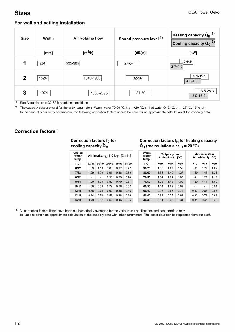
1) See Acoustics on p.30-32 for ambient conditions2) The capacity data are valid for the entry parameters: Warm water 70/50 °C, tL1 = +20 °C; chilled water 6/12 °C, tL1 = 27 °C, 46 % r.h.
In the case of other entry parameters, the following correction factors should be used for an approximate calculation of the capacity data.
Correction factors 3)
Size Width Air volume flow Sound pressure level 1)
[mm] [m3/h] [dB(A)] [kW]
1
2
3
Heating capacity QH 2)
Cooling capacity QC 2)
•
•
924 535-985 27-54 4.3-9.92.7-4.8
1524 1040-1900 32-56 9.1-19.54.9-10.0
1974 1530-2695 34-59 13.5-28.38.0-13.2
Correction factors fC for cooling capacity QC
Correction factors fH for heating capacity QH (recirculation air tL1 = 20 °C)
Chilledwater temp.
Air intake: tL1 [°C], ϕ1 [% r.h.]Warm water temp.
2-pipe systemAir intake: tL1 [°C]
4-pipe systemAir intake: tL1 [°C]
[°C] 32/40 30/40 27/46 26/50 24/50 [°C] +10 +15 +20 +10 +15 +206/12 1.39 1.18 1.00 0.97 0.77 90/70 1.80 1.67 1.55 1.91 1.77 1.627/13 1.29 1.09 0.91 0.88 0.69 80/60 1.53 1.40 1.27 1.59 1.45 1.318/12 - - 0.96 0.93 0.74 70/55 1.34 1.21 1.08 1.41 1.27 1.128/14 1.20 1.00 0.82 0.79 0.61 70/50 1.26 1.13 1.00 1.29 1.14 1.0010/15 1.08 0.89 0.72 0.68 0.52 60/50 1.14 1.02 0.89 - - 0.9412/16 0.86 0.79 0.62 0.58 0.46 60/40 0.98 0.85 0.72 0.97 0.83 0.6812/18 0.84 0.70 0.53 0.48 0.36 50/40 0.88 0.75 0.62 0.92 0.78 0.6314/18 0.79 0.67 0.52 0.46 0.36 40/30 0.61 0.48 0.34 0.81 0.47 0.32
3) All correction factors listed have been mathematically averaged for the various unit applications and can therefore only be used to obtain an approximate calculation of the capacity data with other parameters. The exact data can be requested from our staff.
SizesFor wall and ceiling installation
1.2
• •

3 VK_2052753GB / 12/2005 • Subject to technical modifications
GEA Power Geko
Fig. 2-1: Unit parts (depending on unit application)
1
24
6
7
8
9
10
5
3
11
item 1: Retaining bracket item 2: Heat exchanger item 3: Basic housing with insulation item 4: Filter element item 5: Main condensate tray item 6: Fan with housing
item 7: Sheet-steel electrical control box item 8: Quick-release locks for inspection cover item 9: Inspection cover item 10: Condensate pump item 11: Lateral condensate pan
Components of the fan coil units
2

VK_2052753GB / 12/2005 • Subject to technical modifications 3
GEA Power Geko
Description of the unit
Recirculating air
Coolingand
heating4-pipe chilled and warm water
Coolingor
heating2-pipe chilled or warm water
Heating 2-pipe warm water
Cooling 2-pipe chilled water
Technical data, dimensions and accessory descriptions
Valves
GEA MATRIX control system
4 Rohrreihen Kühlen, 2-Leiter-System
50 60 70 1009080 200
150
450
400
350
300
250
900
800
700
600
500
1000
1500
0,5
3,53,0
2,5
2,0
1,5
1,00,90,80,70,6
8,07,06,0
5,04,54,0
15
109,0
25
20
30
Dru
ckve
rlu
stD
p [
kPa]
2000
65
4
7
12
3
Druckverluste im Wärmetauscher
GEA Top-Geko • ˜nderungen vorbehalten • Stand 08/00 (D) 25
Abb. 25.3
Wasservolumenstrom VW [l/h]
Unit selection

4 VK_2052753GB / 12/2005 • Subject to technical modifications
GEA Power Geko
Basic unit Basic unitHeating/cooling/filtering2-/4-pipe systemCeiling installationPanel structure made of 20 mm Sendzimir-galvanised sheet steel with internal sound attenuation and thermal insulation(Electrical and valve equipment depending on function and requirements)
Basic unit + sound attenuator + discharge plenum Basic unit + air intake sound attenuator + discharge plenum, with sound attenuation and thermal insulation on inner face
Thermoelectric valve equipment Modulating valve equipment Valve equipment2-/3-way valves with actuators for on/off, 230/24 V~ 50/60 Hzmodulating, 230/24 V~ 50/60 Hzcontinuous 24 V~, control sig. 0-10 VFitted and wired
Electrical equipment Electrical equipmentPlastic terminal boxSheet steel electrical control box(as required, depending on model and function of unit)
MATRIX control system Control systemsIn accordance with:Unit applicationValve equipmentInternal/external electronic components
Description of the unit
Fig. 4-1
Fig. 4-2
Fig. 4-3
Fig. 4-4
Fig. 4-5

VK_2052753GB / 12/2005 • Subject to technical modifications 5
GEA Power Geko
Heat exchangerfor warm/chilled water(2-pipe system)
Heat exchangerfor warm/chilled water(4-pipe system)
Copper pipes with attached aluminium fins, coil connection ½" internal thread, vent/drain valves Max. inlet temperature 110 °CMax. operating pressure 16 bar
Centrifugal fans230 V~/50/60 Hz
Centrifugal fans with low-noise, maintenance-free sleeve bearings and high pressure stability, IP20 protection class, insulation class FType and number of fans dependent on unit size and selection
Lateral condensate tray Filter For the collection of condensate from the heat exchanger and valve piping, for pressure-free condensate drainage, made of galvanised sheet steelRegenerative filter hose on changing frame, easy-to-change filter classification G2 (EN 779)
Retaining and assembly angles Retaining and assembly angles provide a number of different options for installing the unit and accessory modules on the ceiling and also for connecting them with one another.
Description of the unit
Fig. 5-2
Fig. 5-3
Fig. 5-4
Fig. 5-1

6 VK_2052753GB / 12/2005 • Subject to technical modifications
GEA Power GekoRecirculation air unit / cooling and heating4-pipe chilled and warm waterSizes 1 to 3
Ext.
pres
sure
*
Fan
spee
ds
Air
volu
me
flow
Capacity stage 1 Capacity stage 2
Soun
d po
wer
–
inta
keSo
und
pow
er –
di
scha
rge
Soun
d po
wer
–
hous
ing
Size
Coo
ling
capa
city
Pres
sure
dro
p
Hea
ting
capa
city
Pres
sure
dro
p
Coo
ling
capa
city
Pres
sure
dro
p
Hea
ting
capa
city
Pres
sure
dro
p
QC ∆pC QH ∆pH QC ∆pC QH ∆pHPa m3/h kW kPa kW kPa kW kPa kW kPa dB(A) dB(A) dB(A)
0
I 535 2.7 12.2 3.3 2.9 – – – – 54 59 48
1
Plastic terminal box(select sheet-steel
electrical control box for GEA MATRIX)
II 655 3.1 15.2 3.6 3.3 – – – – 58 62 50III 735 3.2 16.8 3.8 3.7 – – – – 61 61 50IV 795 3.4 18.1 3.9 3.9 – – – – 63 64 52V 880 3.6 19.9 4.1 4.1 – – – – 64 65 53VI 940 3.7 21.2 4.2 4.4 – – – – 66 66 54VII 985 3.8 22.1 4.3 4.5 – – – – 68 67 54I 1040 5.0 3.8 6.9 4.9 – – – – 56 63 51
2
II 1245 5.6 4.6 7.6 5.8 – – – – 62 64 51III 1410 6.1 5.3 7.9 6.4 – – – – 64 66 52IV 1580 6.5 6.0 8.4 7.0 – – – – 66 67 52V 1690 6.6 6.3 8.6 7.4 – – – – 67 68 53VI 1815 6.9 6.8 8.9 7.9 – – – – 69 69 54 Fan speed combinationVII 1900 7.1 7.1 9.0 8.0 – – – – 70 69 55 1-2-3 AI 1530 8.1 11.2 10.3 12.5 – – – – 60 65 53
3
2-3-4 BII 1810 8.9 13.4 11.2 14.6 – – – – 62 67 53 3-4-5 CIII 2050 9.6 15.2 11.8 16.0 – – – – 65 68 54 4-5-6 DIV 2255 10.0 16.5 12.3 17.4 – – – – 67 69 55 5-6-7 FV 2410 10.3 17.6 12.7 18.3 – – – – 69 70 56 1-4-7 GVI 2550 10.7 18.6 13.0 19.2 – – – – 70 71 58 1-2-3-4-5 HVII 2695 11.0 19.6 13.3 20.1 – – – – 71 72 59
50
I 505 2.6 11.5 3.2 2.7 – – – – 57 59 49
1
II 610 3.0 14.1 3.5 3.1 – – – – 59 61 50III 685 3.1 15.9 3.7 3.5 – – – – 60 62 50 Sheet-steel electrical control box
with terminal strip orfor integrated control
IV 735 3.2 16.8 3.8 3.7 – – – – 62 64 52V 795 3.4 18.1 3.9 3.9 – – – – 62 65 53VI 835 3.5 19.0 4.0 4.0 – – – – 63 66 54VII 880 3.6 19.9 4.1 4.1 – – – – 64 66 54I 920 4.7 3.3 6.5 4.4 – – – – 60 63 51
2
II 1120 5.3 4.4 7.2 5.3 – – – – 61 64 51III 1270 5.7 4.7 7.6 5.9 – – – – 62 66 52IV 1410 6.1 5.3 7.9 6.4 – – – – 63 67 52V 1530 6.3 5.8 8.2 6.8 – – – – 64 68 53VI 1640 6.6 6.2 8.5 7.2 – – – – 65 69 54VII 1720 6.7 6.4 8.7 7.5 – – – – 66 69 55 Fan speed combinationI 1300 7.4 9.4 9.5 10.8 – – – – 62 66 54
3
1-2-3 KII 1565 8.2 11.4 10.4 12.8 – – – – 63 67 53 2-3-4 LIII 1760 8.8 13.0 11.1 14.2 – – – – 64 68 54 3-4-5 MIV 1935 9.3 14.4 11.6 15.5 – – – – 65 69 55 4-5-6 NV 2080 9.6 15.5 11.9 16.2 – – – – 66 70 56 5-6-7 PVI 2200 10.0 16.4 12.2 17.0 – – – – 67 71 58 1-4-7 QVII 2315 10.1 16.9 12.4 17.7 – – – – 68 72 58 1-2-3-4-5 R
1 2Capacity stage
Coil connection** CeilingLeft 3Right 4
Condensate removalVia drain 0Via condensate pump*** 1
• • • •
G P . U W W .Order code
Thermal contact for motor
7-speed motor
TC integrated 0TC with external leads 1
* See pages 24-29 for capacity tables for other external pressures** Connection side from front with view of discharge*** Sheet steel electrical control box required
Warm water 70/50 °CtL1 = +20 °C
Chilled water 6/12 °C tL1 = +27 °C
ϕ1 = 46 % r.h.

VK_2052753GB / 12/2005 • Subject to technical modifications 7
GEA Power Geko Accessories / valve equipmentRecirculation air unit / cooling and heating
4-pipe chilled and warm water, sizes 1 to 3
Accessories
Spare filter hoses 1 1 1
Plenum with circular spigot
Intake 1 0 7
Discharge 2 0 6
—Cap for circular spigot (size-independent)* 3 0 1
Flexible connector
Intake 1 0 6
Discharge 2 0 4
Sound attenuator module
Intake 1 1 4
Discharge 2 1 5
—Suspension rail (size-independent)*
750 mm 0 7 5
1350 mm 1 3 5
1950 mm 1 9 5
Sizes 1 to 3* 0, if size- independent Z G POrder code
Valve equipment
MAT
RIX
200
0
MAT
RIX
300
0/40
00
Ter
min
al b
ox
Heating circuit
Cooling circuit kvs values
Actuator Operating voltage/circuit Cooling/heating
• • • On/off230 V AC T
2 3 8 9
1.60 ≡ 1 624 V AC* Q 2.50 ≡ 2 5
• •
Modulating On/stop/off
230 V AC R0.25 ≡ 0 30.40 ≡ 0 4
• • 24 V AC* N0.63 ≡ 0 61.00 ≡ 1 0
• • 230 V AC with auxiliary switches C1.60 ≡ 1 62.50 ≡ 2 5
• Continuous 0/2...10 V = 24 V AC* S 4.00 ≡ 4 0
• •
Mixed
230 V AC 3-P heating circuit230 V AC 2-P cooling circuit 1
For kvs values, refer to above list. Only 1.6 and
2.5 kvs are possible with on/off actuators (T,Q)
Cooling Heating• • 24 V AC 3-P heating circuit*
24 V AC 2-P cooling circuit* 3
With shut-off valve 1Without shut-off valve 0
V . POrder code* 24 V transformer to be provided by others

8 VK_2052753GB / 12/2005 • Subject to technical modifications
GEA Power Geko
GEA MATRIX 2000System features:
– Definition of temp. 7 ... 40 °C (default 10... 30 °C)– Definition of fan speed– Limitable setting range– Change-over between normal / energy saving
mode on operator panel– Room temperature measurement via operator
panel– External room temperature sensor can be attached– Valve control (2 x on/off)– Temperature control via fan and/or valve(s)– Room frost protection function– Status messages via LED– Group control– Group switch-off in event of malfunction– Motor temperature monitoring
(TC required)– Network-compatible
GEA MATRIX 3000/4000MATRIX 3000 system features
– Definition of temp. 7 ... 40 °C (default 10... 30 °C)– Definition of fan speed– Limitable setting range– Change-over between normal / energy saving
mode on operator panel– Input for change-over between normal / energy
saving mode or unit OFF with frost protection– Room temperature measurement via operator
panel– External room temperature sensor can be attached– Valve control (2 x on/off or 2 x modulating)– Temperature control via fan and/or valve(s)– Room frost protection function– Status messages via LED– Operating and error messaging via volt.-free
change-over contacts– Individual unit or group control– Stand-alone unit switch-off in event of malfunction– Motor temperature monitoring
(TC required)– Network-compatible
Additional features of MATRIX 4000:
– Summer/winter compensation– Silent valve control– Cooling or heating request via volt.-free contacts
(on upstream side)– Stand-alone unit control– Inputs for mode selection:
Normal modeEnergy saving modeFree operating modeUnit OFF
MATRIX OP21COperator panel for MATRIX 2000 control system– Pure white housing, IP20 protection class– Set-point temperature setting– Fan speed selection switch 0 - auto - 1-2-3– Energy saving mode switch– LEDs for operation / malfunction / ext. influence– Integrated room temperature sensor
A
MATRIX OP30COperator panel for MATRIX 3000/4000 control system– Pure white housing, IP20 protection class– Set-point temperature setting– Fan speed selection switch 0 - auto - 1-2-3-4-5– LEDs for operation / malfunction / ext. influence– Integrated room temperature sensor
MATRIX OP31CAs OP30C operator panel, but also includes:– Normal / energy saving mode switch
MATRIX OP44CAs OP31C operator panel, but also includes switches for:– Change-over between recirculation air and
mixed-air operation– Change-over between heating / cooling /
automatic operation
MATRIX OP50COperator panel for MATRIX 3000/4000 control system– Pure white housing, IP20 protection class– Menu-assisted operation via rotating dial– LCD display with plain-text display– Status messages via pictographs– Integrated room temperature sensor
MATRIX OP51CAs OP50C operator panel, but also includes:– Integrated weekly clock timer with programme for
holiday and special switching days
MATRIX.IRInfrared remote control for MATRIX 3000/4000 control system– Black housing, similar to RAL 9004– LCD display approx. 45x30 mm– Functions such as OP44C (without operation,
malfunction and ext. influence messaging, no integr. room temperature sensor)
– Max. range 20 m
B
C
D
21.5°C
100 14:08R E E
F
on off
func
send
- +
%
N
Control equipmentRecirculation air unit / cooling and heating4-pipe chilled and warm water, sizes 1 to 3

VK_2052753GB / 12/2005 • Subject to technical modifications 9
GEA Power Geko
Without return air sensor* 0With return air sensor* 5
Masterunit
Slave
1-15units
Fan
spee
ds
Stan
d-al
one
unit
cont
rol w
ith
oper
atin
g an
der
ror m
essa
ging
Gro
up c
ontr
olw
ith o
pera
ting
and
erro
r mes
sagi
ng
Inpu
t for
uni
t OFF
with
room
fros
t pr
otec
tion
Inpu
t for
ene
rgy
savi
ng c
onta
ct
Supp
ly a
ir te
mpe
ratu
relim
itatio
n
Sile
ntva
lve
cont
rol
Con
tact
for c
oolin
g an
d he
atin
g re
ques
t
Con
nect
ion
for
exte
rior s
enso
r
Up to3-speed
• • 3 1 2 0 1• • 3 2 2 0 1
• • 3 1 3 1• • 3 2 3 2• • • 3 3 3 3• • • 3 4 3 4• • • • 4 1 4 1• • • • 4 2 4 2• • • • • 4 3 4 3• • • • • 4 4 4 4
Up to5-speed
• • • • • • 4 5 4 5• • • • • • • 4 6 4 6
Without return air sensor* 0With return air sensor* 5
Operator panel
D . 2 . A D . 2 . Z D
e.g. 2x2x0.75 Unitronic Bus CAN e.g. 1x2x0.75 Unitronic Bus CAN
3x1.5 mm2 NYM
Masterunit
Slave
1-15units
4x2x0.8 J-Y(ST)Y 4x2x0.8 J-Y(ST)Y
3x1.5 mm2 NYM
230 V ~50 Hz
D 2 . 2 1 . A A D 2 . 2 0 1 . Z D
3x1.5 mm2 NYM
Order code
Order code
230 V ~50 Hz
3x1.5 mm2 NYM Cooling / heating medium
Cooling / heating medium
* Alternative room temperature sensor (see page 57)

10 VK_2052753GB / 12/2005 • Subject to technical modifications
GEA Power GekoRecirculation air unit / cooling or heating2-pipe chilled or warm waterSizes 1 to 3
Ext.
pres
sure
*
Fan
spee
ds
Air
volu
me
flow
Capacity stage 1 Capacity stage 2
Soun
d po
wer
–
inta
keSo
und
pow
er –
di
scha
rge
Soun
d po
wer
–
hous
ing
Size
Coo
ling
capa
city
Pres
sure
dro
p
Hea
ting
capa
city
Pres
sure
dro
p
Coo
ling
capa
city
Pres
sure
dro
p
Hea
ting
capa
city
Pres
sure
dro
p
QC ∆pC QH ∆pH QC ∆pC QH ∆pHPa m3/h kW kPa kW kPa kW kPa kW kPa dB(A) dB(A) dB(A)
0
I 535 2.7 12.2 5.3 4.0 3.4 23.0 6.2 6.5 54 59 48
1
Plastic terminal box(select sheet-steel
electrical control box for GEA MATRIX)
II 655 3.1 15.2 6.0 5.0 3.9 29.3 7.2 8.4 58 62 50III 735 3.2 16.8 6.5 5.7 4.2 32.7 7.7 9.7 61 61 50IV 795 3.4 18.1 6.8 6.2 4.3 35.5 8.1 10.7 63 64 52V 880 3.6 19.9 7.2 6.9 4.6 39.6 8.8 12.2 64 65 53VI 940 3.7 21.2 7.4 7.4 4.7 41.6 9.2 13.2 66 66 54VII 985 3.8 22.1 7.6 7.7 4.9 43.6 9.5 14.1 68 67 54I 1040 5.0 3.8 10.3 1.3 7.0 23.4 12.7 6.6 56 63 51
2
II 1245 5.6 4.6 11.6 1.7 7.9 29.6 14.3 8.3 62 64 51III 1410 6.1 5.3 12.6 1.9 8.6 34.2 15.6 9.7 64 66 52IV 1580 6.5 6.0 13.5 2.2 9.1 38.2 16.8 11.1 66 67 52V 1690 6.6 6.3 14.0 2.4 9.5 41.1 17.6 12.1 67 68 53VI 1815 6.9 6.8 14.6 2.5 9.9 44.3 18.5 13.3 69 69 54 Fan speed combinationVII 1900 7.1 7.1 15.0 2.7 10.1 46.5 19.3 14.3 70 69 55 1-2-3 AI 1530 8.1 11.2 15.4 3.4 9.6 9.1 17.8 2.6 60 65 53
3
2-3-4 BII 1810 8.9 13.4 17.4 4.3 10.7 11.0 20.0 3.3 62 67 53 3-4-5 CIII 2050 9.6 15.2 18.7 4.9 11.5 12.7 21.8 3.9 65 68 54 4-5-6 DIV 2255 10.0 16.5 19.9 5.5 12.2 14.1 23.2 4.3 67 69 55 5-6-7 FV 2410 10.3 17.6 20.8 6.0 12.6 14.9 24.6 4.8 69 70 56 1-4-7 GVI 2550 10.7 18.6 21.5 6.4 13.0 15.8 25.4 5.1 70 71 58 1-2-3-4-5 HVII 2695 11.0 19.6 22.0 6.7 13.4 16.7 26.4 5.5 71 72 59
50
I 505 2.6 11.5 5.1 3.6 3.3 21.7 6.0 6.0 57 59 49
1
II 610 3.0 14.1 5.8 4.6 3.7 26.9 6.8 7.7 59 61 50III 685 3.1 15.9 6.2 5.2 4.0 30.2 7.4 8.9 60 62 50 Sheet-steel electrical control box
with terminal strip orfor integrated control
IV 735 3.2 16.8 6.5 5.7 4.2 32.7 7.7 9.7 62 64 52V 795 3.4 18.1 6.8 6.2 4.3 35.5 8.1 10.7 62 65 53VI 835 3.5 19.0 7.0 6.6 4.5 37.5 8.5 11.5 63 66 54VII 880 3.6 19.9 7.2 6.9 4.6 39.6 8.8 12.2 64 66 54I 920 4.7 3.3 9.4 1.1 6.4 20.3 11.6 5.7 60 63 51
2
II 1120 5.3 4.4 10.9 1.5 7.4 26.3 13.3 7.3 61 64 51III 1270 5.7 4.7 11.7 1.7 8.0 30.3 14.5 8.5 62 66 52IV 1410 6.1 5.3 12.6 1.9 8.6 34.2 15.6 9.7 63 67 52V 1530 6.3 5.8 13.3 2.1 8.9 36.9 16.5 10.7 64 68 53VI 1640 6.6 6.2 13.7 2.3 9.3 39.8 17.3 11.7 65 69 54VII 1720 6.7 6.4 14.1 2.4 9.5 41.8 17.7 12.2 66 69 55 Fan speed combinationI 1300 7.4 9.4 13.8 2.8 8.7 7.5 15.9 2.1 62 66 54
3
1-2-3 KII 1565 8.2 11.4 15.7 3.6 9.8 9.4 18.1 2.7 63 67 53 2-3-4 LIII 1760 8.8 13.0 17.1 4.2 10.5 10.6 19.6 3.2 64 68 54 3-4-5 MIV 1935 9.3 14.4 18.2 4.7 11.1 11.9 21.0 3.6 65 69 55 4-5-6 NV 2080 9.6 15.5 18.9 5.0 11.6 14.9 22.1 3.9 66 70 56 5-6-7 PVI 2200 10.0 16.4 19.6 5.4 12.0 13.7 22.7 4.2 67 71 58 1-4-7 QVII 2315 10.1 16.9 20.2 5.7 12.4 14.5 23.8 4.5 68 72 58 1-2-3-4-5 R
1 2Capacity stage
Coil connection** CeilingLeft 3Right 4
Condensate removalVia drain 0Via condensate pump*** 1
• • • •
G P . U W C .Order code
Thermal contact for motor
7-speed motor
TC integrated 0TC with external leads 1
* See pages 24-29 for capacity tables for other external pressures** Connection side from front with view of discharge*** Sheet steel electrical control box required
Warm water 70/50 °CtL1 = +20 °C
Chilled water 6/12 °C tL1 = +27 °C
ϕ1 = 46 % r.h.

VK_2052753GB / 12/2005 • Subject to technical modifications 11
GEA Power Geko Accessories / valve equipmentRecirculation air unit / cooling or heating
2-pipe chilled or warm water, sizes 1 to 3
Accessories
Spare filter hoses 1 1 1
Plenum with circular spigot
Intake 1 0 7
Discharge 2 0 6
—Cap for circular spigot (size-independent)* 3 0 1
Flexible connector
Intake 1 0 6
Discharge 2 0 4
Sound attenuator module
Intake 1 1 4
Discharge 2 1 5
—Suspension rail (size-independent)*
750 mm 0 7 5
1350 mm 1 3 5
1950 mm 1 9 5
Sizes 1 to 3* 0, if size- independent Z G POrder code
Valve equipment
MAT
RIX
200
0
MAT
RIX
300
0/40
00
Ter
min
al b
ox
Heating circuit/cooling circuit kvs values
Actuator Operating voltage/circuit Cooling/heating
• • • On/off230 V AC T 1.60 ≡ 1 624 V AC* Q 2.50 ≡ 2 5
• • •
Modulating On/stop/off
230 V AC R0.25 ≡ 0 30.40 ≡ 0 4
• • • 24 V AC* N0.63 ≡ 0 61.00 ≡ 1 0
• • • 230 V AC with auxiliary switches C1.60 ≡ 1 62.50 ≡ 2 5
• Continuous 0/2...10 V = 24 V AC* S 4.00 ≡ 4 0
For kvs values, refer to above list. Only 1.6 and
2.5 kvs are possible with on/off actuators (T,Q)
With shut-off valve 1Without shut-off valve 0
V 3 . POrder code* 24 V transformer to be provided by others

12 VK_2052753GB / 12/2005 • Subject to technical modifications
GEA Power Geko
GEA MATRIX 2000System features:
– Definition of temp. 7 ... 40 °C (default 10... 30 °C)– Definition of fan speed– Limitable setting range– Change-over between normal / energy saving
mode on operator panel– Room temperature measurement via operator
panel– Valve control (on/off or modulating)– Temperature control via fan and/or valve(s)– Room frost protection function– Status messages via LED– Group control– Group switch-off in event of malfunction– Motor temperature monitoring
(TC required)– Network-compatible
GEA MATRIX 3000/4000MATRIX 3000 system features
– Definition of temp. 7 ... 40 °C (default 10... 30 °C)– Definition of fan speed– Limitable setting range– Change-over between normal / energy saving
mode on operator panel– Input for change-over between normal / energy
saving mode or unit OFF with frost protection– Room temperature measurement via operator
panel– External room temperature sensor can be attached– Valve control (on/off or modulating)– Temperature control via fan and/or valve– Room frost protection function– Status messages via LED– Operating and error messaging via volt.-free
change-over contacts– Individual unit or group control– Stand-alone unit switch-off in event of malfunction– Motor temperature monitoring
(TC required)– Network-compatible
Additional features of MATRIX 4000:
– Summer/winter compensation– Silent valve control– Cooling or heating request via volt.-free contacts
(on upstream side)– Stand-alone unit control– Inputs for mode selection:
Normal mode Energy saving mode Free operating mode Unit OFF
MATRIX OP21COperator panel for MATRIX 2000 control system– Pure white housing, IP20 protection class– Set-point temperature setting– Fan speed selection switch 0 - auto - 1-2-3– Energy saving mode switch– LEDs for operation / malfunction / ext. influence– Integrated room temperature sensor
A
MATRIX OP30Coperator panel for MATRIX 3000/4000 control system– Pure white housing, IP20 protection class– Set-point temperature setting– Fan speed selection switch 0 - auto - 1-2-3-4-5– LEDs for operation / malfunction / ext. influence– Integrated room temperature sensor
MATRIX OP31CAs OP30C operator panel, but also includes:– Normal / energy saving mode switch
MATRIX OP44CAs OP31C operator panel, but also includes switches for:– Change-over between recirculation air and
mixed-air operation– Change-over between heating / cooling /
automatic operation
MATRIX OP50Coperator panel for MATRIX 3000/4000 control system– Pure white housing, IP20 protection class– Menu-assisted operation via rotating dial– LCD display with plain-text display– Status messages via pictographs– Integrated room temperature sensor
MATRIX OP51CAs OP50C operator panel, but also includes:– Integrated weekly clock timer with programme for
holiday and special switching days
MATRIX.IRInfrared remote control for MATRIX 3000/4000 control system– Black housing, similar to RAL 9004– LCD display approx. 45x30mm– Functions such as OP44C (without operation,
malfunction and ext. influence messaging, no integr. room temperature sensor)
– Max. range 20 m
B
C
D
21.5°C
100 14:08R E E
F
on off
func
send
- +
%
N
Control equipmentRecirculation air unit / cooling or heating2-pipe chilled or warm water, sizes 1 to 3

VK_2052753GB / 12/2005 • Subject to technical modifications 13
GEA Power Geko
Masterunit
Slave
1-15units
Fan
spee
ds
Stan
d-al
one
unit
cont
rol w
ith
oper
atin
g an
der
ror m
essa
ging
Gro
up c
ontr
olw
ith o
pera
ting
and
erro
r mes
sagi
ng
Inpu
t for
uni
t OFF
with
room
fros
t pr
otec
tion
Inpu
t for
ene
rgy
savi
ng c
onta
ct
Supp
ly a
ir te
mpe
ratu
relim
itatio
nSi
lent
valv
e co
ntro
l
Con
tact
for c
oolin
g an
d he
atin
g re
ques
t
Con
nect
ion
for
exte
rior s
enso
r
Up to3-speed
• • 3 1 2 0 1• • 3 2 2 0 1
• • 3 1 3 1• • 3 2 3 2• • • 3 3 3 3• • • 3 4 3 4• • • • 4 1 4 1• • • • 4 2 4 2• • • • • 4 3 4 3• • • • • 4 4 4 4
Up to5-speed
• • • • • • 4 5 4 5• • • • • • • 4 6 4 6
Without return air sensor* 0With return air sensor* 5
operator panel
D . 1 . A D . 1 . Z D
e.g. 2x2x0.75 Unitronic Bus CAN e.g. 1x2x0.75 Unitronic Bus CAN
3x1.5 mm2 NYM
Masterunit
Slave
1-15units
4x2x0.8 J-Y(ST)Y 4x2x0.8 J-Y(ST)Y
3x1.5 mm2 NYM
D 2 . 1 0 1 . A A D 2 . 1 0 1 . Z D
2x2x0.8 J-Y(ST)Y flow sensor
2x2x0.8 J-Y(ST)Y flow sensor
Order code
Order code
230 V ~50 Hz
3x1.5 mm2 NYM
230 V ~50 Hz
3x1.5 mm2 NYM
Cooling / heating medium
Cooling / heating medium
* Alternative room temperature sensor (see page 57)

14 VK_2052753GB / 12/2005 • Subject to technical modifications
GEA Power GekoRecirculation air unit / heating2-pipe warm waterSizes 1 to 3
Ext.
pres
sure
*
Fan
spee
ds
Air
volu
me
flow
Capacity stage 1 Capacity stage 2
Soun
d po
wer
–
inta
keSo
und
pow
er –
di
scha
rge
Soun
d po
wer
–
hous
ing
Size
Coo
ling
capa
city
Pres
sure
dro
p
Hea
ting
capa
city
Pres
sure
dro
p
Coo
ling
capa
city
Pres
sure
dro
p
Hea
ting
capa
city
Pres
sure
dro
p
QC ∆pC QH ∆pH QC ∆pC QH ∆pHPa m3/h kW kPa kW kPa kW kPa kW kPa dB(A) dB(A) dB(A)
0
I 535 – – 5.3 4.0 – – 6.2 6.5 54 59 48
1
Plastic terminal box(select sheet-steel
electrical control box for GEA MATRIX)
II 655 – – 6.0 5.0 – – 7.2 8.4 58 62 50III 735 – – 6.5 5.7 – – 7.7 9.7 61 61 50IV 795 – – 6.8 6.2 – – 8.1 10.7 63 64 52V 880 – – 7.2 6.9 – – 8.8 12.2 64 65 53VI 940 – – 7.4 7.4 – – 9.2 13.2 66 66 54VII 985 – – 7.6 7.7 – – 9.5 14.1 68 67 54I 1040 – – 10.3 1.3 – – 12.7 6.6 56 63 51
2
II 1245 – – 11.6 1.7 – – 14.3 8.3 62 64 51III 1410 – – 12.6 1.9 – – 15.6 9.7 64 66 52IV 1580 – – 13.5 2.2 – – 16.8 11.1 66 67 52V 1690 – – 14.0 2.4 – – 17.6 12.1 67 68 53VI 1815 – – 14.6 2.5 – – 18.5 13.3 69 69 54 Fan speed combinationVII 1900 – – 15.0 2.7 – – 19.3 14.3 70 69 55 1-2-3 AI 1530 – – 15.4 3.4 – – 17.8 2.6 60 65 53
3
2-3-4 BII 1810 – – 17.4 4.3 – – 20.0 3.3 62 67 53 3-4-5 CIII 2050 – – 18.7 4.9 – – 21.8 3.9 65 68 54 4-5-6 DIV 2255 – – 19.9 5.5 – – 23.2 4.3 67 69 55 5-6-7 FV 2410 – – 20.8 6.0 – – 24.6 4.8 69 70 56 1-4-7 GVI 2550 – – 21.5 6.4 – – 25.4 5.1 70 71 58 1-2-3-4-5 HVII 2695 – – 22.0 6.7 – – 26.4 5.5 71 72 59
50
I 505 – – 5.1 3.6 – – 6.0 6.0 57 59 49
1
II 610 – – 5.8 4.6 – – 6.8 7.7 59 61 50III 685 – – 6.2 5.2 – – 7.4 8.9 60 62 50 Sheet-steel electrical control box
with terminal strip orfor integrated control
IV 735 – – 6.5 5.7 – – 7.7 9.7 62 64 52V 795 – – 6.8 6.2 – – 8.1 10.7 62 65 53VI 835 – – 7.0 6.6 – – 8.5 11.5 63 66 54VII 880 – – 7.2 6.9 – – 8.8 12.2 64 66 54I 920 – – 9.4 1.1 – – 11.6 5.7 60 63 51
2
II 1120 – – 10.9 1.5 – – 13.3 7.3 61 64 51III 1270 – – 11.7 1.7 – – 14.5 8.5 62 66 52IV 1410 – – 12.6 1.9 – – 15.6 9.7 63 67 52V 1530 – – 13.3 2.1 – – 16.5 10.7 64 68 53VI 1640 – – 13.7 2.3 – – 17.3 11.7 65 69 54VII 1720 – – 14.1 2.4 – – 17.7 12.2 66 69 55 Fan speed combinationI 1300 – – 13.8 2.8 – – 15.9 2.1 62 66 54
3
1-2-3 KII 1565 – – 15.7 3.6 – – 18.1 2.7 63 67 53 2-3-4 LIII 1760 – – 17.1 4.2 – – 19.6 3.2 64 68 54 3-4-5 MIV 1935 – – 18.2 4.7 – – 21.0 3.6 65 69 55 4-5-6 NV 2080 – – 18.9 5.0 – – 22.1 3.9 66 70 56 5-6-7 PVI 2200 – – 19.6 5.4 – – 22.7 4.2 67 71 58 1-4-7 QVII 2315 – – 20.2 5.7 – – 23.8 4.5 68 72 58 1-2-3-4-5 R
1 2Capacity stage
Coil connection** CeilingLeft 3Right 4
• • • •
G P . U 0 W . 0Order code
Thermal contact for motor
7-speed motor
TC integrated 0TC with external leads 1
* See pages 24-29 for capacity tables for other external pressures** Connection side from front with view of discharge
Warm water 70/50 °CtL1 = +20 °C

VK_2052753GB / 12/2005 • Subject to technical modifications 15
GEA Power Geko Accessories / valve equipmentRecirculation air unit / heating
2-pipe warm water, sizes 1 to 3
Accessories
Spare filter hoses 1 1 1
Plenum with circular spigot
Intake 1 0 7
Discharge 2 0 6
—Cap for circular spigot (size-independent)* 3 0 1
Flexible connector
Intake 1 0 6
Discharge 2 0 4
Sound attenuator module
Intake 1 1 4
Discharge 2 1 5
—Suspension rail (size-independent)*
750 mm 0 7 5
1350 mm 1 3 5
1950 mm 1 9 5
Sizes 1 to 3* 0, if size- independent Z G POrder code
Valve equipment
MAT
RIX
200
0
MAT
RIX
300
0/40
00
Ter
min
al b
ox
Heating circuit kvs values
Actuator Operating voltage/circuit Heating
• • • On/off230 V AC T
2 3
1.60 ≡ 1 624 V AC* Q 2.50 ≡ 2 5
• • •
Modulating On/stop/off
230 V AC R0.25 ≡ 0 30.40 ≡ 0 4
• • • 24 V AC* N0.63 ≡ 0 61.00 ≡ 1 0
• • • 230 V AC with auxiliary switches C1.60 ≡ 1 62.50 ≡ 2 5
• Continuous 0/2...10 V = 24 V AC* S 4.00 ≡ 4 0
For kvs values, refer to above list. Only 1.6 and
2.5 kvs are possible with on/off actuators (T,Q)
With shut-off valve 1Without shut-off valve 0
V . POrder code* 24 V transformer to be provided by others

16 VK_2052753GB / 12/2005 • Subject to technical modifications
GEA Power Geko
GEA MATRIX 2000System features:
– Definition of temp. 7 ... 40 °C (default 10... 30 °C)– Definition of fan speed– Limitable setting range– Change-over between normal / energy saving
mode on operator panel– Room temperature measurement via operator
panel– External room temperature sensor can be attached– Valve control (on/off or modulating)– Temperature control via fan and/or valve– Room frost protection function– Status messages via LED– Group control– Group switch-off in event of malfunction– Motor temperature monitoring
(TC required)– Network-compatible
GEA MATRIX 3000/4000MATRIX 3000 system features
– Definition of temp. 7 ... 40 °C (default 10... 30 °C)– Definition of fan speed– Limitable setting range– Change-over between normal / energy saving
mode on operator panel– Input for change-over between normal / energy
saving mode or unit OFF with frost protection– Room temperature measurement via operator
panel– External room temperature sensor can be attached– Valve control (on/off or modulating)– Temperature control via fan and/or valve– Room frost protection function– Status messages via LED– Operating and error messaging via volt.-free
change-over contacts– Individual unit or group control– Stand-alone unit switch-off in event of malfunction– Motor temperature monitoring
(TC required)– Network-compatible
Additional features of MATRIX 4000:
– Summer/winter compensation– Silent valve control– Heating request via volt.-free contact (on upstream
side)– Stand-alone unit control– Inputs for mode selection:
Normal mode Energy saving mode Free operating mode Unit OFF
MATRIX OP21Coperator panel for MATRIX 2000 control system– Pure white housing, IP20 protection class– Set-point temperature setting– Fan speed selection switch 0 - auto - 1-2-3– Energy saving mode switch– LEDs for operation / malfunction / ext. influence– Integrated room temperature sensor
A
MATRIX OP30Coperator panel for MATRIX 3000/4000 control system– Pure white housing, IP20 protection class– Set-point temperature setting– Fan speed selection switch 0 - auto - 1-2-3-4-5– LEDs for operation / malfunction / ext. influence– Integrated room temperature sensor
MATRIX OP31CAs OP30C operator panel, but also includes:– Normal / energy saving mode switch
MATRIX OP50Coperator panel for MATRIX 3000/4000 control system– Pure white housing, IP20 protection class– Menu-assisted operation via rotating dial– LCD display with plain-text display– Status messages via pictographs– Integrated room temperature sensor
MATRIX OP51CAs OP50C operator panel, but also includes:– Integrated weekly clock timer with programme for
holiday and special switching days
MATRIX.IRInfrared remote control for MATRIX 3000/4000 control system– Black housing, similar to RAL 9004– LCD display approx. 45x30mm– Functions such as OP44C (without operation,
malfunction and ext. influence messaging, no integr. room temperature sensor)
– Max. range 20 m
B
C
21.5°C
100 14:08R E E
F
on off
func
send
- +
% N
Control equipmentRecirculation air unit / heating2-pipe warm water, sizes 1 to 3

VK_2052753GB / 12/2005 • Subject to technical modifications 17
GEA Power Geko
Without return air sensor* 0With return air sensor* 5
Masterunit
Slave
1-15units
Fan
spee
ds
Stan
d-al
one
unit
cont
rol w
ith
oper
atin
g an
der
ror m
essa
ging
Gro
up c
ontr
olw
ith o
pera
ting
and
erro
r mes
sagi
ng
Inpu
t for
uni
t OFF
with
room
fros
t pr
otec
tion
Inpu
t for
ene
rgy
savi
ng c
onta
ct
Supp
ly a
ir te
mpe
ratu
relim
itatio
n
Sile
ntva
lve
cont
rol
Con
tact
for
heat
ing
requ
est
Con
nect
ion
for
exte
rior s
enso
r
Up to3-speed
• • 3 1 2 0 1• • 3 2 2 0 1
• • 3 1 3 1• • 3 2 3 2• • • 3 3 3 3• • • 3 4 3 4• • • • 4 1 4 1• • • • 4 2 4 2• • • • • 4 3 4 3• • • • • 4 4 4 4
Up to5-speed
• • • • • • 4 5 4 5• • • • • • • 4 6 4 6
Without return air sensor* 0With return air sensor* 5
operator panel
D . 0 . A D . 0 . Z D
e.g. 2x2x0.75 Unitronic Bus CAN e.g. 1x2x0.75 Unitronic Bus CAN
3x1.5 mm2 NYM
Masterunit
Slave
1-15units
4x2x0.8 J-Y(ST)Y 4x2x0.8 J-Y(ST)Y
3x1.5 mm2 NYM
D 2 . 0 1 . A A D 2 . 0 0 1 . Z DOrder code
Order code
230 V ~50 Hz
3x1.5 mm2 NYM
230 V ~50 Hz
3x1.5 mm2 NYM
Heating medium
Heating medium
* Alternative room temperature sensor (see page 57)

18 VK_2052753GB / 12/2005 • Subject to technical modifications
GEA Power GekoRecirculation air unit / cooling2-pipe chilled waterSizes 1 to 3
Ext.
pres
sure
*
Fan
spee
ds
Air
volu
me
flow
Capacity stage 1 Capacity stage 2
Soun
d po
wer
–
inta
keSo
und
pow
er –
di
scha
rge
Soun
d po
wer
–
hous
ing
Size
Coo
ling
capa
city
Pres
sure
dro
p
Hea
ting
capa
city
Pres
sure
dro
p
Coo
ling
capa
city
Pres
sure
dro
p
Hea
ting
capa
city
Pres
sure
dro
p
QC ∆pC QH ∆pH QC ∆pC QH ∆pHPa m3/h kW kPa kW kPa kW kPa kW kPa dB(A) dB(A) dB(A)
0
I 535 2.7 12.2 – – 3.4 23.0 – – 54 59 48
1
Plastic terminal box(select sheet-steel
electrical control box for GEA MATRIX)
II 655 3.1 15.2 – – 3.9 29.3 – – 58 62 50III 735 3.2 16.8 – – 4.2 32.7 – – 61 61 50IV 795 3.4 18.1 – – 4.3 35.5 – – 63 64 52V 880 3.6 19.9 – – 4.6 39.6 – – 64 65 53VI 940 3.7 21.2 – – 4.7 41.6 – – 66 66 54VII 985 3.8 22.1 – – 4.9 43.6 – – 68 67 54I 1040 5.0 3.8 – – 7.0 23.4 – – 56 63 51
2
II 1245 5.6 4.6 – – 7.9 29.6 – – 62 64 51III 1410 6.1 5.3 – – 8.6 34.2 – – 64 66 52IV 1580 6.5 6.0 – – 9.1 38.2 – – 66 67 52V 1690 6.6 6.3 – – 9.5 41.1 – – 67 68 53VI 1815 6.9 6.8 – – 9.9 44.3 – – 69 69 54 Fan speed combinationVII 1900 7.1 7.1 – – 10.1 46.5 – – 70 69 55 1-2-3 AI 1530 8.1 11.2 – – 9.6 9.1 – – 60 65 53
3
2-3-4 BII 1810 8.9 13.4 – – 10.7 11.0 – – 62 67 53 3-4-5 CIII 2050 9.6 15.2 – – 11.5 12.7 – – 65 68 54 4-5-6 DIV 2255 10.0 16.5 – – 12.2 14.1 – – 67 69 55 5-6-7 FV 2410 10.3 17.6 – – 12.6 14.9 – – 69 70 56 1-4-7 GVI 2550 10.7 18.6 – – 13.0 15.8 – – 70 71 58 1-2-3-4-5 HVII 2695 11.0 19.6 – – 13.4 16.7 – – 71 72 59
50
I 505 2.6 11.5 – – 3.3 21.7 – – 57 59 49
1
II 610 3.0 14.1 – – 3.7 26.9 – – 59 61 50III 685 3.1 15.9 – – 4.0 30.2 – – 60 62 50 Sheet-steel electrical control box
with terminal strip orfor integrated control
IV 735 3.2 16.8 – – 4.2 32.7 – – 62 64 52V 795 3.4 18.1 – – 4.3 35.5 – – 62 65 53VI 835 3.5 19.0 – – 4.5 37.5 – – 63 66 54VII 880 3.6 19.9 – – 4.6 39.6 – – 64 66 54I 920 4.7 3.3 – – 6.4 20.3 – – 60 63 51
2
II 1120 5.3 4.1 – – 7.4 26.3 – – 61 64 51III 1270 5.7 4.7 – – 8.0 30.3 – – 62 66 52IV 1410 6.1 5.3 – – 8.6 34.2 – – 63 67 52V 1530 6.3 5.8 – – 8.9 36.9 – – 64 68 53VI 1640 6.6 6.2 – – 9.3 39.8 – – 65 69 54VII 1720 6.7 6.4 – – 9.5 41.8 – – 66 69 55 Fan speed combinationI 1300 7.4 9.4 – – 8.7 7.5 – – 62 66 54
3
1-2-3 KII 1565 8.2 11.4 – – 9.8 9.4 – – 63 67 53 2-3-4 LIII 1760 8.8 13.0 – – 10.5 10.6 – – 64 68 54 3-4-5 MIV 1935 9.3 14.4 – – 11.1 11.9 – – 65 69 55 4-5-6 NV 2080 9.6 15.5 – – 11.6 12.9 – – 66 70 56 5-6-7 PVI 2200 10.0 16.4 – – 12.0 13.7 – – 67 71 58 1-4-7 QVII 2315 10.1 16.9 – – 12.4 14.5 – – 68 72 58 1-2-3-4-5 R
1 2Capacity stage
Coil connection** CeilingLeft 3Right 4
Condensate removalVia drain 0Via condensate pump*** 1
• • • •
G P . U W O .Order code
Thermal contact for motor
7-speed motor
TC integrated 0TC with external leads 1
* See pages 24-29 for capacity tables for other external pressures** Connection side from front with view of discharge*** Sheet-steel electrical control box required
Chilled water 6/12 °C tL1 = +27 °C
ϕ1 = 46 % r.h.

VK_2052753GB / 12/2005 • Subject to technical modifications 19
GEA Power Geko Accessories / valve equipmentRecirculation air unit / cooling
2-pipe chilled water, sizes 1 to 3
Accessories
Spare filter hoses 1 1 1
Plenum with circular spigot
Intake 1 0 7
Discharge 2 0 6
—Cap for circular spigot (size-independent)* 3 0 1
Flexible connector
Intake 1 0 6
Discharge 2 0 4
Sound attenuator module
Intake 1 1 4
Discharge 2 1 5
—Suspension rail (size-independent)*
750 mm 0 7 5
1350 mm 1 3 5
1950 mm 1 9 5
Sizes 1 to 3* 0, if size- independent Z G POrder code
Valve equipment
MAT
RIX
200
0
MAT
RIX
300
0/40
00
Ter
min
al b
ox
Cooling circuit kvs values
Actuator Operating voltage/circuit Cooling
• • • On/off230 V AC T
2 3
1.60 ≡ 1 624 V AC* Q 2.50 ≡ 2 5
• • •
Modulating On/stop/off
230 V AC R0.25 ≡ 0 30.40 ≡ 0 4
• • • 24 V AC* N0.63 ≡ 0 61.00 ≡ 1 0
• • • 230 V AC with auxiliary switches C1.60 ≡ 1 62.50 ≡ 2 5
• Continuous 0/2...10 V = 24 V AC* S 4.00 ≡ 4 0
For kvs values, refer to above list. Only 1.6 and
2.5 kvs are possible with on/off actuators (T,Q)
With shut-off valve 1Without shut-off valve 0
V . POrder code* 24 V transformer to be provided by others

20 VK_2052753GB / 12/2005 • Subject to technical modifications
GEA Power Geko
GEA MATRIX 2000System features:
– Definition of temp. 7 ... 40 °C (default 10... 30 °C)– Definition of fan speed– Limitable setting range– Change-over between normal / energy saving
mode on operator panel– Room temperature measurement via operator
panel– External room temperature sensor can be attached– Valve control (on/off or modulating)– Temperature control via fan and/or valve– Status messages via LED– Group control– Group switch-off in event of malfunction– Motor temperature monitoring
(TC required)– Network-compatible
GEA MATRIX 3000/4000MATRIX 3000 system features
– Definition of temp. 7 ... 40 °C (default 10... 30 °C)– Definition of fan speed– Limitable setting range– Change-over between normal / energy saving
mode on operator panel– Input for change-over between normal / energy
saving mode or unit OFF with frost protection– Room temperature measurement via operator
panel– External room temperature sensor can be attached– Valve control (on/off or modulating)– Temperature control via fan and/or valve– Status messages via LED– Operating and error messaging via volt.-free
change-over contacts– Individual unit or group control– Stand-alone unit switch-off in event of malfunction– Motor temperature monitoring
(TC required)– Network-compatible
Additional features of MATRIX 4000:
– Summer/winter compensation– Silent valve control– Cooling request via volt.-free contacts (on
upstream side)– Stand-alone unit control– Inputs for mode selection:
Normal mode Energy saving mode Free operating mode Unit OFF
MATRIX OP21COperator panel for MATRIX 2000 control system– Pure white housing, IP20 protection class– Set-point temperature setting– Fan speed selection switch 0 - auto - 1-2-3– Energy saving mode switch– LEDs for operation / malfunction / ext. influence– Integrated room temperature sensor
A
MATRIX OP30COperator panel for MATRIX 3000/4000 control system– Pure white housing, IP20 protection class– Set-point temperature setting– Fan speed selection switch 0 - auto - 1-2-3-4-5– LEDs for operation / malfunction / ext. influence– Integrated room temperature sensor
MATRIX OP31CAs OP30C operator panel, but also includes:– Normal / energy saving mode switch
MATRIX OP50COperator panel for MATRIX 3000/4000 control system– Pure white housing, IP20 protection class– Menu-assisted operation via rotating dial– LCD display with plain-text display– Status messages via pictographs– Integrated room temperature sensor
MATRIX OP51CAs OP50C operator panel, but also includes:– Integrated weekly clock timer with programme for
holiday and special switching days
MATRIX.IRInfrared remote control for MATRIX 3000/4000 control system– Black housing, similar to RAL 9004– LCD display approx. 45x30mm– Functions such as OP44C (without operation,
malfunction and ext. influence messaging, no integr. room temperature sensor)
– Max. range 20 m
B
C
21.5°C
100 14:08R E E
F
on off
func
send
- +
%
N
Control equipmentRecirculation air unit / cooling2-pipe chilled water, sizes 1 to 3

VK_2052753GB / 12/2005 • Subject to technical modifications 21
GEA Power Geko
Without return air sensor* 0With return air sensor* 5
Fan
spee
ds
Stan
d-al
one
unit
cont
rol w
ith
oper
atin
g an
der
ror m
essa
ge
Gro
up c
ontr
olw
ith o
pera
ting
and
erro
r mes
sagi
ng
Inpu
t for
uni
t OFF
with
room
fros
t pr
otec
tion
Inpu
t for
ene
rgy
savi
ng c
onta
ct
Supp
ly a
ir te
mpe
ratu
relim
itatio
n
Sile
ntva
lve
cont
rol
Con
tact
for
cool
ing
requ
est
Con
nect
ion
for
exte
rior s
enso
r
Up to3-speed
• • 3 1 2 0 1• • 3 2 2 0 1
• • 3 1 3 1• • 3 2 3 2• • • 3 3 3 3• • • 3 4 3 4• • • • 4 1 4 1• • • • 4 2 4 2• • • • • 4 3 4 3• • • • • 4 4 4 4
Up to5-speed
• • • • • • 4 5 4 5• • • • • • • 4 6 4 6
Without return air sensor* 0With return air sensor* 5
Operator panel
Masterunit
Slave
1-15units
D . 0 . A D . 0 . Z D
e.g. 2x2x0.75 Unitronic Bus CAN e.g. 1x2x0.75 Unitronic Bus CAN
3x1.5 mm2 NYM
Masterunit
Slave
1-15units
4x2x0.8 J-Y(ST)Y 4x2x0.8 J-Y(ST)Y
3x1.5 mm2 NYM
D 2 . 0 1 . A A D 2 . 0 0 1 . Z D
Control of external heating valve on request
Order code
Order code
230 V ~50 Hz
3x1.5 mm2 NYM
230 V ~50 Hz
3x1.5 mm2 NYM
Cooling medium
Cooling medium
* Alternative room temperature sensor (see page 57)

22 VK_2052753GB / 12/2005 • Subject to technical modifications
GEA Power Geko
50 60 70 1009080 200
150
450
400
350
300
250
900
800
700
600
500
1000
1500
0,5
3,5
3,0
2,5
2,0
1,5
1,00,90,80,7
0,6
8,07,0
6,0
5,04,54,0
15
109,0
25
20
30
2000
12
3
50 60 70 1009080 200
150
450
400
350
300
250
900
800
700
600
500
1000
1500
0,5
3,5
3,0
2,5
2,0
1,5
1,00,90,80,7
0,6
8,07,0
6,0
5,04,54,0
15
109,0
25
20
30
2000
50 60 70 1009080 200
150
450
400
350
300
250
900
800
700
600
500
1000
1500
0,5
3,5
3,0
2,5
2,0
1,5
1,00,90,80,7
0,6
8,07,0
6,0
5,04,54,0
15
109,0
25
20
30
2000 50 60 70 10
09080 200
150
450
400
350
300
250
900
800
700
600
500
1000
1500
0,5
3,5
3,0
2,5
2,0
1,5
1,00,90,80,7
0,6
8,07,0
6,0
5,04,54,0
15
109,0
25
20
30
2000
1
2
3
1,2
1,1
2,2
3,1
2,1
3,2
2
1
3
Fig. 22-1
P
ress
ure
drop
[kPa
]
LG 2, cooling, 2-pipe system
P
ress
ure
drop
[kPa
]
LG 1, cooling, 2- or 4-pipe system
Water flow rate Vw [l/h]• Water flow rate Vw [l/h]•
P
ress
ure
drop
[kP
a]
Heating, 2-pipe system
P
ress
ure
drop
[kP
a]
LG 1, heating, 4-pipe system
Water flow rate Vw [l/h]• Water flow rate Vw [l/h]•
S*
S,LG*
Fig. 22-2
Fig. 22-3 Fig. 22-4
* S = size, LG = capacity stage
S*
S*
Coil pressure dropsfor warm and chilled water

VK_2052753GB / 12/2005 • Subject to technical modifications 23
GEA Power Geko
Note: The power and current consumption falls with external pressure. The exact data can be requested from our staff.
The tables on pages 6 to 21 specify the heating capacities for warm water 70/50 °C and air intake temperature tL1= +20 °C and the cooling capacities for chilled water 6/12 °C and air intake condition tL1=+27 °C/46 % r.h.Capacities in other operating statuses can be ascertained using the correction factors listed on fold-out page 1.2.Sample calculation for a recirculation air Power Geko for cooling or heating with 2-pipe system to provide a heating capacity of at least 13 kW for warm water 70/50/+15 °C and cooling with chilled water 8/12 (24/50) °C
Selected unit type: GP21.UWC3.B00See page 10Sample level 3 = 1410 m3/h
(at 0 Pa ext. pressure)
Heating capacity with warm water 70/50 °C and tL1 = + 15 °C
QH (70/50/+15) = new heating capacityfH (70/50/+15) = 1.13 (see p.1.2)QH (70/50/+20) = 12.6 (see p.10)
Cooling capacity with chilled water 8/12°C and tL1= +24°C/50% r.h.
QC (8/12/+24/50%) = new cooling capacityfC (8/12/+24/50%) = 0.74 (see p.1.2)QC (6/12/+27/46%) = 6.1 (see p.6)
Max. power and current consumption
Size Speed Air volume flow[m3/h]
MotorPower [W] Current [A]
1
1 535 130 0.59
2 655 154 0.69
3 735 158 0.71
4 795 160 0.73
5 880 177 0.79
6 940 188 0.83
7 985 208 0.93
2
1 1040 262 1.16
2 1245 278 1.23
3 1410 298 1.27
4 1580 315 1.40
5 1690 338 1.48
6 1815 388 1.72
7 1900 402 1.91
3
1 1530 394 1.72
2 1810 424 1.86
3 2050 438 1.93
4 2255 458 2.00
5 2410 494 2.15
6 2550 539 2.34
7 2695 589 2.55
•
•
QH (70/50/+15) = fH (70/50/+15) • QH (70/50/+20) ••
QH (70/50/+15) = 1.13 • 12.6kW = 14.2kW •
•
•
••QC (8/12/+24/50%) = fC (8/12/+24/50%) • QC (6/12/+27/46%)
QC (8/12/+24/50%) = 0.74 • 6.1kW = 4.5 kW •
Example of capacity determination

24 VK_2052753GB / 12/2005 • Subject to technical modifications
GEA Power Geko
Ext.
pres
sure
Fan
spee
ds
Air
volu
mef
low
Capacity stage 1 Capacity stage 2
Coo
ling
capa
city
Pres
sure
dro
p
Hea
ting
capa
city
Pres
sure
dro
p
Coo
ling
capa
city
Pres
sure
dro
p
Hea
ting
capa
city
Pres
sure
dro
p
QC ∆pC QH ∆pH QC ∆pC QH ∆pH
Pa m3/h kW kPa kW kPa kW kPa kW kPa
0
I 535 2.7 12.2 5.3 4.0 3.4 23.0 6.2 6.5
II 655 3.1 15.2 6.0 5.0 3.9 29.3 7.2 8.4
III 735 3.2 16.8 6.5 5.7 4.2 32.7 7.7 9.7
IV 795 3.4 18.1 6.8 6.2 4.3 35.5 8.1 10.7
V 880 3.6 19.9 7.2 6.9 4.6 39.6 8.8 12.2
VI 940 3.7 21.2 7.4 7.4 4.7 41.6 9.2 13.2
VII 985 3.8 22.1 7.6 7.7 4.9 43.6 9.5 14.1
25
I 525 2.7 12.0 5.2 3.8 3.4 22.9 6.2 6.4
II 645 3.0 14.9 6.0 4.9 3.9 28.8 7.1 8.2
III 720 3.2 16.7 6.4 5.5 4.1 31.9 7.6 9.5
IV 775 3.3 17.6 6.7 6.0 4.3 34.6 8.0 10.2
V 845 3.5 19.2 7.1 6.7 4.5 37.9 8.6 11.8
VI 895 3.6 20.3 7.2 7.0 4.7 40.3 8.9 12.5
VII 940 3.7 21.2 7.4 7.4 4.7 41.6 9.2 13.2
50
I 505 2.6 11.5 5.1 3.6 3.3 21.7 6.0 6.0
II 610 3.0 14.0 5.8 4.6 3.7 26.9 6.8 7.7
III 685 3.1 15.9 6.2 5.2 4.0 30.2 7.4 8.9
IV 735 3.2 16.8 6.5 5.7 4.2 32.7 7.7 9.7
V 795 3.4 18.1 6.8 6.2 4.3 35.5 8.1 10.7
VI 835 3.5 19.0 7.0 6.6 4.5 37.5 8.5 11.5
VII 880 3.6 19.9 7.2 6.9 4.6 39.6 8.8 12.2
75
I 440 2.5 10.0 4.6 3.0 3.0 18.0 5.4 5.1
II 550 2.8 12.6 5.4 4.0 3.5 23.8 6.4 6.7
III 605 2.9 14.0 5.8 4.6 3.7 26.7 6.8 7.6
IV 670 3.1 15.5 6.1 5.1 3.9 29.5 7.3 8.6
V 715 3.2 16.6 6.4 5.5 4.1 31.9 7.6 9.4
VI 760 3.3 17.3 6.6 5.9 4.2 33.9 7.9 10.1
VII 805 3.4 18.3 6.8 6.3 4.4 36.0 8.2 10.9
100
I 345 2.1 7.6 3.9 2.2 2.6 13.3 4.5 3.6
II 430 2.4 9.7 4.5 2.9 3.0 17.5 5.4 4.9
III 480 2.6 11.0 4.9 3.4 3.2 20.3 5.8 5.7
IV 540 2.7 12.4 5.3 3.9 3.5 23.3 6.3 6.6
V 610 3.0 14.4 5.8 4.6 3.7 26.9 6.8 7.7
VI 650 3.1 15.0 6.0 4.9 3.9 29.0 7.1 8.3
VII 685 3.1 15.9 6.2 5.2 4.0 30.2 7.4 8.9
125
I – – – – – – – – –
II – – – – – – – – –
III – – – – – – – – –
IV 400 2.3 8.9 4.3 2.7 2.8 15.8 5.1 4.5
V 460 2.5 10.5 4.8 3.2 3.1 19.1 5.6 5.4
VI 490 2.6 11.3 4.9 3.4 3.3 21.1 5.9 5.8
VII 515 2.7 11.7 5.2 3.7 3.4 22.3 6.1 6.2
•• • •
Capacity overview for different external pressures
Size 1, 2-pipe system
Warm water 70/50 °CtL1 = +20 °C
Chilled water 6/12 °C tL1 = +27 °C
ϕ1 = 46 % r.h.

VK_2052753GB / 12/2005 • Subject to technical modifications 25
GEA Power Geko Capacity overview for different external pressures
Size 1, 4-pipe system
Ext.
pres
sure
Fan
spee
ds
Air
volu
mef
low
Capacity stage 1 Capacity stage 2
Coo
ling
capa
city
Pres
sure
dro
p
Hea
ting
capa
city
Pres
sure
dro
p
Coo
ling
capa
city
Pres
sure
dro
p
Hea
ting
capa
city
Pres
sure
dro
p
QC ∆pC QH ∆pH QC ∆pC QH ∆pH
Pa m3/h kW kPa kW kPa kW kPa kW kPa
0
I 535 2.7 12.2 3.3 2.9 – – – –
II 655 3.1 15.2 3.6 3.3 – – – –
III 735 3.2 16.8 3.8 3.7 – – – –
IV 795 3.4 18.1 3.9 3.9 – – – –
V 880 3.6 19.9 4.1 4.1 – – – –
VI 940 3.7 21.2 4.2 4.4 – – – –
VII 985 3.8 22.1 4.3 4.5 – – – –
25
I 525 2.7 12.0 3.3 2.8 – – – –
II 645 3.0 14.9 3.6 3.3 – – – –
III 720 3.2 16.7 3.8 3.6 – – – –
IV 775 3.3 17.6 3.9 3.8 – – – –
V 845 3.5 19.2 4.0 4.0 – – – –
VI 895 3.6 20.3 4.1 4.2 – – – –
VII 940 3.7 21.2 4.2 4.4 – – – –
50
I 505 2.6 11.5 3.2 2.7 – – – –
II 610 3.0 14.0 3.5 3.1 – – – –
III 685 3.1 15.9 3.7 3.5 – – – –
IV 735 3.2 16.8 3.8 3.7 – – – –
V 795 3.4 18.1 3.9 3.9 – – – –
VI 835 3.5 19.0 4.0 4.0 – – – –
VII 880 3.6 19.9 4.1 4.1 – – – –
75
I 440 2.5 10.0 3.0 2.4 – – – –
II 550 2.8 12.6 3.4 2.9 – – – –
III 605 2.9 14.0 3.5 3.1 – – – –
IV 670 3.1 15.5 3.6 3.4 – – – –
V 715 3.2 16.6 3.8 3.6 – – – –
VI 760 3.3 17.3 3.9 3.8 – – – –
VII 805 3.4 18.3 4.0 3.9 – – – –
100
I 345 2.1 7.6 2.6 1.9 – – – –
II 430 2.4 9.7 3.0 2.3 – – – –
III 480 2.6 11.0 3.1 2.6 – – – –
IV 540 2.7 12.4 3.3 2.9 – – – –
V 610 3.0 14.4 3.5 3.1 – – – –
VI 650 3.1 15.0 3.6 3.3 – – – –
VII 685 3.1 15.9 3.7 3.5 – – – –
125
I – – – – – – – – –
II – – – – – – – – –
III – – – – – – – – –
IV 400 2.3 8.9 2.9 2.2 – – – –
V 460 2.5 10.5 3.1 2.5 – – – –
VI 490 2.6 11.3 3.2 2.6 – – – –
VII 515 2.7 11.7 3.2 2.8 – – – –
• • • •
Warm water 70/50 °CtL1 = +20 °C
Chilled water 6/12 °C tL1 = +27 °C
ϕ1 = 46 % r.h.

26 VK_2052753GB / 12/2005 • Subject to technical modifications
GEA Power GekoCapacity overview for different external pressures
Size 2, 2-pipe systemEx
t. pr
essu
re
Fan
spee
ds
Air
volu
mef
low
Capacity stage 1 Capacity stage 2
Coo
ling
capa
city
Pres
sure
dro
p
Hea
ting
capa
city
Pres
sure
dro
p
Coo
ling
capa
city
Pres
sure
dro
p
Hea
ting
capa
city
Pres
sure
dro
p
QC ∆pC QH ∆pH QC ∆pC QH ∆pH
Pa m3/h kW kPa kW kPa kW kPa kW kPa
0
I 1040 5.0 3.8 10.3 1.3 7.0 23.4 12.7 6.6
II 1245 5.6 4.6 11.6 1.7 7.9 29.6 14.3 8.3
III 1410 6.1 5.3 12.6 1.9 8.6 34.2 15.6 9.7
IV 1580 6.5 6.0 13.5 2.2 9.1 38.2 16.8 11.1
V 1690 6.6 6.3 14.0 2.4 9.5 41.1 17.6 12.1
VI 1815 6.9 6.8 14.6 2.5 9.9 44.3 18.5 13.3
VII 1900 7.1 7.1 15.0 2.7 10.1 46.5 19.3 14.3
25
I 1010 4.9 3.6 10.2 1.3 6.9 22.9 12.4 6.4
II 1215 5.5 4.5 11.4 1.6 7.8 28.7 14.1 8.0
III 1380 6.0 5.2 12.4 1.9 8.4 33.4 15.4 9.4
IV 1530 6.3 5.8 13.3 2.1 8.9 36.9 16.5 10.7
V 1620 6.6 6.1 13.6 2.2 9.2 39.2 17.1 11.5
VI 1740 6.7 6.5 14.2 2.4 9.6 42.3 17.9 12.4
VII 1820 6.9 6.8 14.6 2.6 9.9 44.4 18.6 13.3
50
I 920 4.7 3.3 9.4 1.1 6.4 20.3 11.6 5.7
II 1120 5.3 4.1 10.9 1.5 7.4 26.3 13.3 7.3
III 1270 5.7 4.7 11.7 1.7 8.0 30.3 14.5 8.5
IV 1410 6.1 5.3 12.6 1.9 8.6 34.2 15.6 9.7
V 1530 6.3 5.8 13.3 2.1 8.9 36.9 16.5 10.7
VI 1640 6.6 6.2 13.7 2.3 9.3 39.8 17.3 11.7
VII 1720 6.7 6.4 14.1 2.4 9.5 41.88 17.7 12.2
75
I 800 4.3 2.8 8.5 0.9 5.9 17.3 10.4 4.6
II 980 4.8 3.5 9.9 1.2 6.7 21.0 12.2 6.1
III 1115 5.3 4.1 10.8 1.5 7.5 26.6 13.3 7.2
IV 1245 5.6 4.6 11.6 1.7 7.9 29.6 14.3 8.3
V 1350 5.9 5.1 12.2 1.8 8.3 32.5 15.1 9.2
VI 1445 6.1 5.4 12.8 2.0 8.7 35.2 15.9 10.0
VII 1535 6.4 5.8 13.3 2.1 9.0 37.0 16.5 10.8
100
I 665 3.7 2.2 7.4 0.7 5.2 13.6 9.0 3.6
II 820 4.3 2.9 8.7 1.0 6.0 17.8 10.6 4.8
III 935 4.7 3.3 9.5 1.1 6.5 20.7 11.8 5.8
IV 1040 5.0 3.8 10.3 1.3 7.0 23.4 12.7 6.6
V 1150 5.4 4.2 11.1 1.5 7.6 27.3 13.6 7.5
VI 1220 5.6 4.5 11.4 1.6 7.8 28.9 14.1 8.1
VII 1300 5.8 4.9 11.9 1.7 8.1 31.1 14.8 8.7
125
I – – – – – – – – –
II – – – – – – – – –
III 725 4.0 2.4 7.9 0.8 5.5 15.3 9.6 4.0
IV 825 4.4 2.9 8.7 1.0 6.0 18.0 10.6 4.8
V 920 4.7 3.3 9.4 1.1 6.4 20.3 11.6 5.7
VI 985 4.9 3.5 9.9 1.2 6.8 22.2 12.2 6.2
VII 1050 5.1 3.8 10.4 1.3 7.0 23.8 12.8 6.7
• • • •
Warm water 70/50 °CtL1 = +20 °C
Chilled water 6/12 °C tL1 = +27 °C
ϕ1 = 46 % r.h.

VK_2052753GB / 12/2005 • Subject to technical modifications 27
GEA Power Geko Capacity overview for different external pressures
Size 2, 4-pipe system
Ext.
pres
sure
Fan
spee
ds
Air
volu
mef
low
Capacity stage 1 Capacity stage 2
Coo
ling
capa
city
Pres
sure
dro
p
Hea
ting
capa
city
Pres
sure
dro
p
Coo
ling
capa
city
Pres
sure
dro
p
Hea
ting
capa
city
Pres
sure
dro
p
QC ∆pC QH ∆pH QC ∆pC QH ∆pH
Pa m3/h kW kPa kW kPa kW kPa kW kPa
0
I 1040 5.0 3.8 6.9 4.9 – – – –
II 1245 5.6 4.6 7.6 5.8 – – – –
III 1410 6.1 5.3 7.9 6.4 – – – –
IV 1580 6.5 6.0 8.4 7.0 – – – –
V 1690 6.6 6.3 8.6 7.4 – – – –
VI 1815 6.9 6.8 8.9 7.9 – – – –
VII 1900 7.1 7.1 9.0 8.0 – – – –
25
I 1010 4.9 3.6 6.8 4.8 – – – –
II 1215 5.5 4.5 7.5 5.7 – – – –
III 1380 6.0 5.2 7.9 6.2 – – – –
IV 1530 6.3 5.8 8.2 6.8 – – – –
V 1620 6.6 6.1 8.4 7.2 – – – –
VI 1740 6.7 6.5 8.7 7.6 – – – –
VII 1820 6.9 6.8 8.9 7.9 – – – –
50
I 920 4.7 3.3 6.5 4.4 – – – –
II 1120 5.3 4.1 7.2 5.3 – – – –
III 1270 5.7 4.7 7.6 5.9 – – – –
IV 1410 6.1 5.3 7.9 6.4 – – – –
V 1530 6.3 5.8 8.2 6.8 – – – –
VI 1640 6.6 6.2 8.5 7.2 – – – –
VII 1720 6.7 6.4 8.7 7.5 – – – –
75
I 800 4.3 2.8 6.0 3.8 – – – –
II 980 4.8 3.5 6.7 4.6 – – – –
III 1115 5.3 4.1 7.1 5.2 – – – –
IV 1245 5.6 4.6 7.6 5.8 – – – –
V 1350 5.9 5.1 7.8 6.1 – – – –
VI 1445 6.1 5.4 8.0 6.5 – – – –
VII 1535 6.4 5.8 8.2 6.8 – – – –
100
I 665 3.7 2.2 5.4 3.1 – – – –
II 820 4.3 2.9 6.1 3.9 – – – –
III 935 4.7 3.3 6.5 4.4 – – – –
IV 1040 5.0 3.8 6.9 4.9 – – – –
V 1150 5.4 4.2 7.3 5.4 – – – –
VI 1220 5.6 4.5 7.5 5.7 – – – –
VII 1300 5.8 4.9 7.6 5.9 – – – –
125
I – – – – – – – – –
II – – – – – – – – –
III 725 4.0 2.4 5.7 3.4 – – – –
IV 825 4.4 2.9 6.1 3.9 – – – –
V 920 4.7 3.3 6.5 4.4 – – – –
VI 985 4.9 3.5 6.7 4.6 – – – –
VII 1050 5.1 3.8 6.9 4.9 – – – –
• • • •
Warm water 70/50 °CtL1 = +20 °C
Chilled water 6/12 °C tL1 = +27 °C
ϕ1 = 46 % r.h.

28 VK_2052753GB / 12/2005 • Subject to technical modifications
GEA Power GekoCapacity overview for different external pressures
Size 3, 2-pipe systemEx
t. pr
essu
re
Fan
spee
ds
Air
volu
mef
low
Capacity stage 1 Capacity stage 2
Coo
ling
capa
city
Pres
sure
dro
p
Hea
ting
capa
city
Pres
sure
dro
p
Coo
ling
capa
city
Pres
sure
dro
p
Hea
ting
capa
city
Pres
sure
dro
p
QC ∆pC QH ∆pH QC ∆pC QH ∆pH
Pa m3/h kW kPa kW kPa kW kPa kW kPa
0
I 1530 8.1 11.2 15.4 3.4 9.6 9.1 17.8 2.6
II 1810 8.9 13.4 17.4 4.3 10.7 11.0 20.0 3.3
III 2050 9.6 15.2 18.7 4.9 11.5 12.7 21.8 3.9
IV 2255 10.0 16.5 19.9 5.5 12.2 14.1 23.2 4.3
V 2410 10.3 17.6 20.8 6.0 12.6 14.9 24.6 4.8
VI 2550 10.7 18.6 21.5 6.4 13.0 15.8 25.4 5.1
VII 2695 11.0 19.6 22.0 6.7 13.4 16.7 26.4 5.5
25
I 1470 8.0 10.9 15.1 3.3 9.4 8.7 17.3 2.5
II 1745 8.7 12.9 17.0 4.1 10.4 10.5 19.5 3.1
III 1970 9.4 14.6 18.3 4.7 11.3 12.1 21.2 3.7
IV 2155 9.8 16.0 19.4 5.2 11.9 13.4 22.6 4.1
V 2300 10.1 16.8 20.2 5.7 12.4 14.4 23.6 4.5
VI 2435 10.4 17.8 20.9 6.0 12.7 15.0 24.8 4.9
VII 2550 10.7 18.6 21.5 6.4 13.0 15.8 25.4 5.1
50
I 1300 7.4 9.4 13.8 2.8 8.7 7.5 15.9 2.1
II 1565 8.2 11.4 15.7 3.6 9.8 9.4 18.1 2.7
III 1760 8.8 13.0 17.1 4.2 10.5 10.6 19.6 3.2
IV 1935 9.3 14.4 18.2 4.7 11.1 11.9 21.0 3.6
V 2080 9.6 15.5 18.9 5.0 11.6 12.9 22.1 3.9
VI 2200 10.0 16.4 19.6 5.4 12.0 13.7 22.7 4.2
VII 2315 10.1 16.9 20.2 5.7 12.4 14.5 23.8 4.5
75
I 1115 6.7 7.9 12.4 2.3 7.7 6.0 14.2 1.7
II 1340 7.5 9.8 14.1 2.9 8.9 7.8 16.2 2.2
III 1510 8.1 11.2 15.2 3.4 9.6 9.0 17.6 2.6
IV 1675 8.5 12.3 16.5 3.9 10.3 10.2 19.0 3.0
V 1810 8.9 13.4 17.4 4.3 10.7 11.0 20.0 3.3
VI 1920 9.2 14.2 18.1 4.7 11.1 11.8 20.9 3.5
VII 2025 9.5 15.0 18.6 4.9 11.4 12.5 21.7 3.8
100
I 910 5.8 6.2 10.7 1.8 6.6 4.6 12.0 1.3
II 1075 6.6 7.6 12.1 2.2 7.4 5.7 13.8 1.7
III 1220 7.1 8.8 13.2 2.6 8.2 6.7 15.1 2.0
IV 1380 7.7 10.1 14.4 3.0 9.1 8.1 16.5 2.3
V 1510 8.1 11.2 15.2 3.4 9.6 9.0 17.6 2.6
VI 1620 8.4 11.9 16.2 3.8 10.0 9.8 18.5 2.8
VII 1715 8.6 12.6 16.8 4.0 10.4 10.5 19.3 3.1
125
I 655 4.5 3.9 8.4 1.1 5.2 2.9 9.2 0.8
II 775 5.2 4.9 9.5 1.4 5.9 3.7 10.5 1.0
III 905 5.8 6.1 10.7 1.8 6.6 4.6 12.0 1.3
IV 1050 6.5 7.4 11.9 2.1 7.4 5.6 13.6 1.6
V 1190 7.0 8.5 13.0 2.5 8.1 6.6 14.9 1.9
VI 1260 7.2 9.1 13.5 2.7 8.4 7.1 15.5 2.0
VII 1355 7.6 9.9 14.2 3.0 8.9 7.9 16.3 2.3
• • • •
Warm water 70/50 °CtL1 = +20 °C
Chilled water 6/12 °C tL1 = +27 °C
ϕ1 = 46 % r.h.

VK_2052753GB / 12/2005 • Subject to technical modifications 29
GEA Power Geko Capacity overview for different external pressures
Size 3, 4-pipe system
Ext.
pres
sure
Fan
spee
ds
Air
volu
mef
low
Capacity stage 1 Capacity stage 2
Coo
ling
capa
city
Pres
sure
dro
p
Hea
ting
capa
city
Pres
sure
dro
p
Coo
ling
capa
city
Pres
sure
dro
p
Hea
ting
capa
city
Pres
sure
dro
p
QC ∆pC QH ∆pH QC ∆pC QH ∆pH
Pa m3/h kW kPa kW kPa kW kPa kW kPa
0
I 1530 8.1 11.2 10.3 12.5 – – – –
II 1810 8.9 13.4 11.2 14.6 – – – –
III 2050 9.6 15.2 11.8 16.0 – – – –
IV 2255 10.0 16.5 12.3 17.4 – – – –
V 2410 10.3 17.6 12.7 18.3 – – – –
VI 2550 10.7 18.6 13.0 19.2 – – – –
VII 2695 11.0 19.6 13.3 20.1 – – – –
25
I 1470 8.0 10.9 10.2 12.3 – – – –
II 1745 8.7 12.9 11.0 14.1 – – – –
III 1970 9.4 14.6 11.7 15.8 – – – –
IV 2155 9.8 16.0 12.1 16.7 – – – –
V 2300 10.1 16.8 12.4 17.6 – – – –
VI 2435 10.4 17.8 12.7 18.5 – – – –
VII 2550 10.7 18.6 13.0 19.2 – – – –
50
I 1300 7.4 9.4 9.5 10.8 – – – –
II 1565 8.2 11.4 10.4 12.8 – – – –
III 1760 8.8 13.0 11.1 14.2 – – – –
IV 1935 9.3 14.4 11.6 15.5 – – – –
V 2080 9.6 15.5 11.9 16.2 – – – –
VI 2200 10.0 16.4 12.2 17.0 – – – –
VII 2315 10.1 16.9 12.4 17.7 – – – –
75
I 1115 6.7 7.9 8.8 9.4 – – – –
II 1340 7.5 9.8 9.7 11.2 – – – –
III 1510 8.1 11.2 10.2 12.4 – – – –
IV 1675 8.5 12.3 10.8 13.6 – – – –
V 1810 8.9 13.4 11.2 14.6 – – – –
VI 1920 9.2 14.2 11.5 15.4 – – – –
VII 2025 9.5 15.0 11.8 16.2 – – – –
100
I 910 5.8 6.2 7.7 7.3 – – – –
II 1075 6.6 7.6 8.6 9.0 – – – –
III 1220 7.1 8.8 9.2 10.1 – – – –
IV 1380 7.7 10.1 9.9 11.5 – – – –
V 1510 8.1 11.2 10.2 12.4 – – – –
VI 1620 8.4 11.9 10.6 13.2 – – – –
VII 1715 8.6 12.6 10.9 13.9 – – – –
125
I 655 4.5 3.9 6.3 5.1 – – – –
II 775 5.2 4.9 7.0 6.2 – – – –
III 905 5.8 6.1 7.7 7.3 – – – –
IV 1050 6.5 7.4 8.5 8.8 – – – –
V 1190 7.0 8.5 9.1 9.9 – – – –
VI 1260 7.2 9.1 9.4 10.5 – – – –
VII 1355 7.6 9.9 9.8 11.3 – – – –
• • • •
Warm water 70/50 °CtL1 = +20 °C
Chilled water 6/12 °C tL1 = +27 °C
ϕ1 = 46 % r.h.

30 VK_2052753GB / 12/2005 • Subject to technical modifications
GEA Power Geko
Basic unit
Basic unit + sound attenuator, suction and discharge side
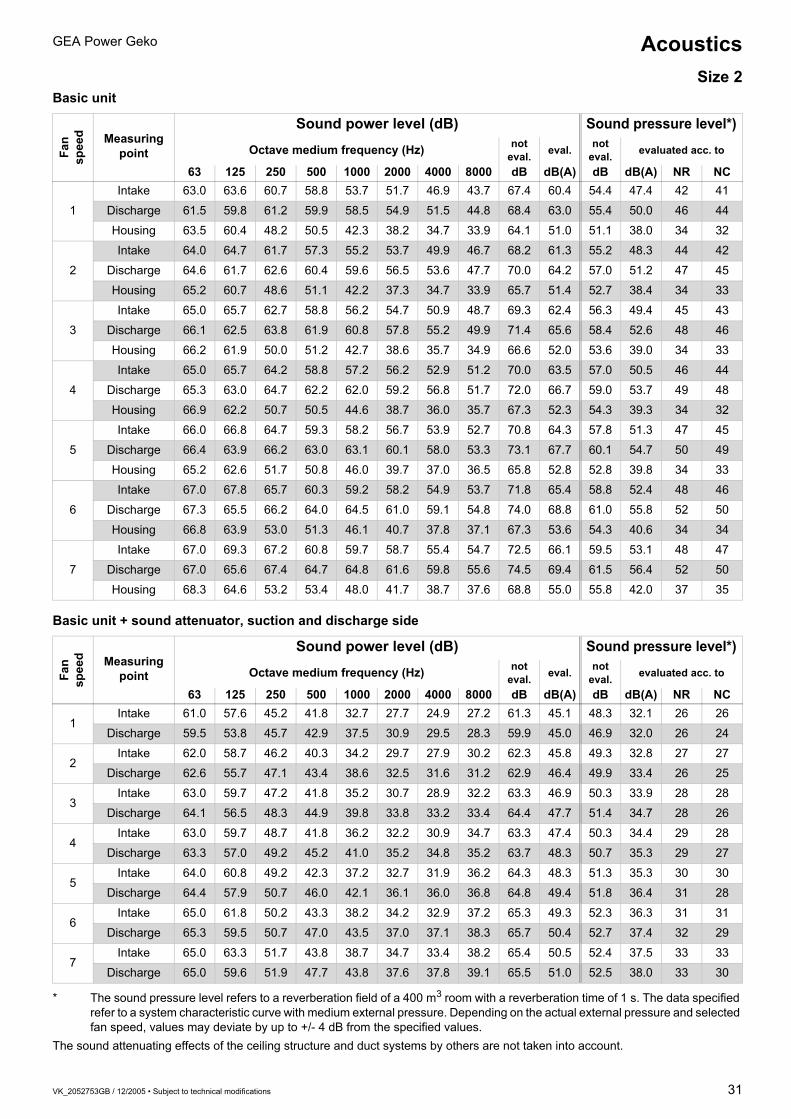
* The sound pressure level refers to a reverberation field of a 400 m3 room with a reverberation time of 1 s. The data specified refer to a system characteristic curve with medium external pressure. Depending on the actual external pressure and selected fan speed, values may deviate by up to +/- 4 dB from the specified values.
The sound attenuating effects of the ceiling structure and duct systems by others are not taken into account.
Fan
spee
d Measuring point
Sound power level (dB) Sound pressure level*)
Octave medium frequency (Hz) not eval. eval. not
eval. evaluated acc. to
63 125 250 500 1000 2000 4000 8000 dB dB(A) dB dB(A) NR NC
1
Intake 58.0 57.3 58.0 53.8 51.2 49.2 43.9 40.6 63.5 57.0 50.5 44.0 39 37
Discharge 58.0 56.8 56.6 53.9 54.1 51.3 47.6 41.3 64.0 58.5 51.0 45.5 41 40
Housing 59.0 55.8 47.1 47.5 41.7 35.6 30.5 27.8 60.0 48.2 47.0 35.2 30 29
2
Intake 61.0 59.7 59.6 55.2 53.7 51.7 46.9 43.2 65.8 59.1 52.8 46.1 42 40
Discharge 60.3 57.2 58.4 55.2 56.7 53.9 51.0 45.2 66.2 61.0 53.2 48.0 44 42
Housing 61.6 57.4 49.5 49.1 43.2 37.3 32.9 30.5 62.4 50.0 49.4 37.0 32 31
3
Intake 61.0 60.3 60.1 55.2 54.7 53.2 49.9 46.7 66.4 60.2 53.4 47.2 43 41
Discharge 60.8 58.5 59.7 56.6 58.3 55.3 52.9 47.3 67.5 62.5 54.5 49.5 45 44
Housing 60.7 58.0 50.1 48.5 44.3 38.5 34.4 32.3 61.7 50.3 48.7 37.3 32 30
4
Intake 62.0 61.2 62.1 57.8 56.2 54.2 50.9 48.7 67.9 61.8 54.9 48.8 44 42
Discharge 62.0 61.2 61.6 58.8 59.9 56.8 54.3 49.2 69.1 64.2 56.1 51.2 47 45
Housing 60.8 59.2 52.1 50.7 46.1 40.1 36.3 35.0 62.3 52.1 49.3 39.1 34 32
5
Intake 65.0 62.5 62.7 57.2 56.7 55.2 51.9 49.7 69.2 62.4 56.2 49.4 45 43
Discharge 63.2 60.4 61.8 58.7 61.0 57.9 55.7 50.8 70.0 65.1 57.0 52.1 48 47
Housing 61.8 59.2 52.4 50.7 47.3 40.6 37.0 35.6 63.1 52.6 50.1 39.6 34 33
6
Intake 64.0 62.5 63.7 57.8 57.5 55.7 52.9 51.2 69.5 63.2 56.5 50.2 46 44
Discharge 67.2 61.6 62.7 59.6 62.0 58.8 56.6 52.0 71.8 66.0 58.8 53.0 49 48
Housing 61.8 59.3 53.2 51.2 50.2 41.5 38.0 36.8 63.5 54.0 50.5 41.0 37 36
7
Intake 64.0 64.0 64.7 59.3 58.2 56.7 54.0 52.2 70.2 64.2 57.2 51.2 47 45
Discharge 64.0 64.0 64.5 61.1 62.9 59.2 57.0 52.2 71.7 66.9 58.7 53.9 50 48
Housing 62.0 59.5 53.7 52.3 50.3 41.8 38.5 37.2 63.8 54.5 50.8 41.5 37 36
Fan
spee
d Measuring point
Sound power level (dB) Sound pressure level*)
Octave medium frequency (Hz) not eval. eval. not
eval. evaluated acc. to
63 125 250 500 1000 2000 4000 8000 dB dB(A) dB dB(A) NR NC
1Intake 56.0 51.3 42.5 36.8 30.2 26.2 21.9 24.6 56.4 40.4 43.4 27.4 20 18
Discharge 56.0 50.8 41.1 36.9 33.1 28.3 25.6 25.3 56.3 40.7 43.3 27.7 20 18
2Intake 59.0 53.7 44.1 38.2 32.7 28.7 24.9 27.2 59.3 42.6 46.3 29.6 22 21
Discharge 58.3 51.2 42.9 38.2 35.7 30.9 29.0 29.2 58.6 42.5 45.6 29.5 23 21
3Intake 59.0 54.3 44.6 38.2 33.7 30.2 27.9 30.7 59.3 43.2 46.3 30.2 25 22
Discharge 58.8 52.5 44.2 39.6 37.3 32.3 30.9 31.3 59.2 43.9 46.2 30.9 26 23
4Intake 60.0 55.2 46.6 40.8 35.2 31.2 28.9 32.7 60.4 44.8 47.4 32.8 27 24
Discharge 60.0 55.2 46.1 41.8 38.9 33.8 32.3 33.2 60.4 45.8 47.4 32.8 27 25
5Intake 63.0 56.5 47.2 40.2 35.7 32.2 29.9 33.7 63.2 45.7 50.2 32.7 28 25
Discharge 61.2 54.4 46.3 41.7 40.0 34.9 33.7 34.8 61.6 46.3 48.6 33.3 29 26
6Intake 62.0 56.5 48.2 40.8 36.7 32.7 30.9 35.2 62.3 46.1 49.3 33.1 29 27
Discharge 65.2 55.6 47.2 42.6 41.0 35.8 34.6 36.0 65.4 47.6 52.4 34.6 30 27
7Intake 62.0 58.0 49.2 42.3 37.2 33.7 32.0 36.2 62.4 47.2 49.4 34.2 30 27
Discharge 62.0 58.0 49.0 44.1 41.9 36.2 35.0 36.2 62.5 48.5 49.5 35.5 30 27
AcousticsSize 1
VK_2052753GB / 12/2005 • Subject to technical modifications 31
GEA Power Geko
Basic unit
Basic unit + sound attenuator, suction and discharge side
* The sound pressure level refers to a reverberation field of a 400 m3 room with a reverberation time of 1 s. The data specified refer to a system characteristic curve with medium external pressure. Depending on the actual external pressure and selected fan speed, values may deviate by up to +/- 4 dB from the specified values.
The sound attenuating effects of the ceiling structure and duct systems by others are not taken into account.
Fan
spee
d Measuring point
Sound power level (dB) Sound pressure level*)
Octave medium frequency (Hz) not eval. eval. not
eval. evaluated acc. to
63 125 250 500 1000 2000 4000 8000 dB dB(A) dB dB(A) NR NC
1
Intake 63.0 63.6 60.7 58.8 53.7 51.7 46.9 43.7 67.4 60.4 54.4 47.4 42 41
Discharge 61.5 59.8 61.2 59.9 58.5 54.9 51.5 44.8 68.4 63.0 55.4 50.0 46 44
Housing 63.5 60.4 48.2 50.5 42.3 38.2 34.7 33.9 64.1 51.0 51.1 38.0 34 32
2
Intake 64.0 64.7 61.7 57.3 55.2 53.7 49.9 46.7 68.2 61.3 55.2 48.3 44 42
Discharge 64.6 61.7 62.6 60.4 59.6 56.5 53.6 47.7 70.0 64.2 57.0 51.2 47 45
Housing 65.2 60.7 48.6 51.1 42.2 37.3 34.7 33.9 65.7 51.4 52.7 38.4 34 33
3
Intake 65.0 65.7 62.7 58.8 56.2 54.7 50.9 48.7 69.3 62.4 56.3 49.4 45 43
Discharge 66.1 62.5 63.8 61.9 60.8 57.8 55.2 49.9 71.4 65.6 58.4 52.6 48 46
Housing 66.2 61.9 50.0 51.2 42.7 38.6 35.7 34.9 66.6 52.0 53.6 39.0 34 33
4
Intake 65.0 65.7 64.2 58.8 57.2 56.2 52.9 51.2 70.0 63.5 57.0 50.5 46 44
Discharge 65.3 63.0 64.7 62.2 62.0 59.2 56.8 51.7 72.0 66.7 59.0 53.7 49 48
Housing 66.9 62.2 50.7 50.5 44.6 38.7 36.0 35.7 67.3 52.3 54.3 39.3 34 32
5
Intake 66.0 66.8 64.7 59.3 58.2 56.7 53.9 52.7 70.8 64.3 57.8 51.3 47 45
Discharge 66.4 63.9 66.2 63.0 63.1 60.1 58.0 53.3 73.1 67.7 60.1 54.7 50 49
Housing 65.2 62.6 51.7 50.8 46.0 39.7 37.0 36.5 65.8 52.8 52.8 39.8 34 33
6
Intake 67.0 67.8 65.7 60.3 59.2 58.2 54.9 53.7 71.8 65.4 58.8 52.4 48 46
Discharge 67.3 65.5 66.2 64.0 64.5 61.0 59.1 54.8 74.0 68.8 61.0 55.8 52 50
Housing 66.8 63.9 53.0 51.3 46.1 40.7 37.8 37.1 67.3 53.6 54.3 40.6 34 34
7
Intake 67.0 69.3 67.2 60.8 59.7 58.7 55.4 54.7 72.5 66.1 59.5 53.1 48 47
Discharge 67.0 65.6 67.4 64.7 64.8 61.6 59.8 55.6 74.5 69.4 61.5 56.4 52 50
Housing 68.3 64.6 53.2 53.4 48.0 41.7 38.7 37.6 68.8 55.0 55.8 42.0 37 35
Fan
spee
d Measuring point
Sound power level (dB) Sound pressure level*)
Octave medium frequency (Hz) not eval. eval. not
eval. evaluated acc. to
63 125 250 500 1000 2000 4000 8000 dB dB(A) dB dB(A) NR NC
1Intake 61.0 57.6 45.2 41.8 32.7 27.7 24.9 27.2 61.3 45.1 48.3 32.1 26 26
Discharge 59.5 53.8 45.7 42.9 37.5 30.9 29.5 28.3 59.9 45.0 46.9 32.0 26 24
2Intake 62.0 58.7 46.2 40.3 34.2 29.7 27.9 30.2 62.3 45.8 49.3 32.8 27 27
Discharge 62.6 55.7 47.1 43.4 38.6 32.5 31.6 31.2 62.9 46.4 49.9 33.4 26 25
3Intake 63.0 59.7 47.2 41.8 35.2 30.7 28.9 32.2 63.3 46.9 50.3 33.9 28 28
Discharge 64.1 56.5 48.3 44.9 39.8 33.8 33.2 33.4 64.4 47.7 51.4 34.7 28 26
4Intake 63.0 59.7 48.7 41.8 36.2 32.2 30.9 34.7 63.3 47.4 50.3 34.4 29 28
Discharge 63.3 57.0 49.2 45.2 41.0 35.2 34.8 35.2 63.7 48.3 50.7 35.3 29 27
5Intake 64.0 60.8 49.2 42.3 37.2 32.7 31.9 36.2 64.3 48.3 51.3 35.3 30 30
Discharge 64.4 57.9 50.7 46.0 42.1 36.1 36.0 36.8 64.8 49.4 51.8 36.4 31 28
6Intake 65.0 61.8 50.2 43.3 38.2 34.2 32.9 37.2 65.3 49.3 52.3 36.3 31 31
Discharge 65.3 59.5 50.7 47.0 43.5 37.0 37.1 38.3 65.7 50.4 52.7 37.4 32 29
7Intake 65.0 63.3 51.7 43.8 38.7 34.7 33.4 38.2 65.4 50.5 52.4 37.5 33 33
Discharge 65.0 59.6 51.9 47.7 43.8 37.6 37.8 39.1 65.5 51.0 52.5 38.0 33 30
AcousticsSize 2

32 VK_2052753GB / 12/2005 • Subject to technical modifications
GEA Power GekoAcousticsSize 3Basic unit
Basic unit + sound attenuator, suction and discharge side
* The sound pressure level refers to a reverberation field of a 400 m3 room with a reverberation time of 1 s. The data specified refer to a system characteristic curve with medium external pressure. Depending on the actual external pressure and selected fan speed, values may deviate by up to +/- 4 dB from the specified values.
= values extracted for the example, see page 33/34.The sound attenuating effects of the ceiling structure and duct systems by others are not taken into account.
Fan
spee
d Measuring point
Sound power level (dB) Sound pressure level*)
Octave medium frequency (Hz) not eval. eval. not
eval. evaluated acc. to
63 125 250 500 1000 2000 4000 8000 dB dB(A) dB dB(A) NR NC
1
Intake 65.0 65.8 63.2 58.3 55.2 53.7 49.4 44.7 69.1 61.7 56.1 48.7 44 42
Discharge 64.0 61.7 64.4 61.6 61.0 56.4 53.5 46.6 70.8 65.1 57.8 52.1 48 47
Housing 65.6 59.0 51.7 53.3 44.8 38.9 38.6 31.2 66.3 53.0 53.3 40.0 36 35
2
Intake 66.0 65.8 64.7 58.8 56.7 55.2 51.4 47.7 70.3 63.0 57.3 50.0 45 43
Discharge 65.4 62.9 65.7 62.6 62.3 58.1 55.5 49.2 72.1 66.5 59.1 53.5 49 48
Housing 67.0 59.6 52.7 52.1 44.5 40.1 38.4 33.8 67.5 52.8 54.5 39.8 35 34
3
Intake 66.0 67.3 65.2 59.8 57.7 56.2 52.4 49.7 70.8 64.0 57.8 51.0 46 44
Discharge 66.7 63.2 66.9 63.4 63.7 59.4 57.2 51.3 73.4 67.8 60.4 54.8 51 49
Housing 69.1 60.2 53.6 52.7 45.7 41.4 39.7 35.9 69.5 53.7 56.5 40.7 36 35
4
Intake 67.0 67.8 66.2 60.8 58.7 57.7 53.9 51.7 71.9 65.1 58.9 52.1 47 46
Discharge 67.4 64.4 67.8 64.3 64.6 60.5 58.5 52.9 74.3 68.8 61.3 55.8 52 50
Housing 68.1 61.1 55.3 52.8 47.8 42.3 40.7 37.3 68.7 54.6 55.7 41.6 36 35
5
Intake 66.0 68.8 67.2 61.8 59.7 59.2 55.9 53.7 72.4 66.4 59.4 53.4 49 47
Discharge 68.2 65.8 68.9 65.1 65.8 62.3 60.4 55.4 75.4 70.2 62.4 57.2 53 51
Housing 68.7 61.2 56.6 53.6 49.6 43.4 41.7 38.6 69.3 55.6 56.3 42.6 37 36
6
Intake 67.0 69.9 68.2 62.3 61.2 60.7 56.9 55.2 73.5 67.6 60.5 45.6 50 49
Discharge 69.2 67.2 69.8 66.2 66.7 63.4 61.6 56.7 76.4 71.2 63.4 58.2 54 52
Housing 69.5 62.2 57.6 56.2 51.8 46.0 43.0 40.5 70.3 57.6 57.3 44.6 39 38
7
Intake 69.0 71.9 68.7 63.8 61.7 60.7 57.4 55.7 74.5 68.2 61.5 55.2 50 49
Discharge 69.6 68.1 70.5 66.9 67.5 63.9 62.3 57.5 77.1 71.9 64.1 58.9 55 53
Housing 70.6 66.3 57.6 57.7 51.2 46.2 43.0 40.6 71.3 58.5 58.3 45.5 41 40
Fan
spee
d Measuring point
Sound power level (dB) Sound pressure level*)
Octave medium frequency (Hz) not eval. eval. not
eval. evaluated acc. to
63 125 250 500 1000 2000 4000 8000 dB dB(A) dB dB(A) NR NC
1Intake 63.0 58.8 49.2 43.3 36.2 31.7 27.4 26.7 63.3 47.2 50.3 34.2 27 27
Discharge 62.0 54.7 50.4 46.6 42.0 34.4 31.5 28.6 62.6 48.4 49.6 35.4 30 28
2Intake 64.0 58.8 50.7 43.8 37.7 33.2 29.4 29.7 64.4 48.0 51.4 35.0 28 27
Discharge 63.4 55.9 51.7 47.6 43.3 36.1 33.5 31.2 64.0 49.7 51.0 36.7 31 29
3Intake 64.0 60.3 51.2 44.8 38.7 34.2 30.4 31.7 64.4 48.9 51.4 35.9 29 29
Discharge 64.7 56.2 52.9 48.4 44.7 37.4 35.2 33.3 65.3 50.8 52.3 37.8 32 30
4Intake 65.0 60.8 52.2 45.8 39.7 35.7 31.9 33.7 65.4 49.8 52.4 36.8 30 30
Discharge 65.4 57.4 53.8 49.3 45.6 38.5 36.5 34.9 66.0 51.7 53.0 38.7 33 31
5Intake 64.0 61.8 53.2 46.8 40.7 37.2 33.9 35.7 64.6 50.8 51.6 37.8 31 31
Discharge 66.2 58.8 54.9 50.1 46.8 40.3 38.4 37.4 66.9 52.9 53.9 39.9 34 32
6Intake 65.0 62.9 54.2 47.3 42.2 38.7 34.9 37.2 65.6 51.8 52.6 38.8 32 32
Discharge 67.2 60.2 55.8 51.2 47.7 41.4 39.6 38.7 67.9 53.9 54.9 40.9 35 33
7Intake 67.0 64.9 54.7 48.8 42.7 38.7 35.4 37.7 67.5 53.1 54.5 40.1 34 35
Discharge 67.6 61.1 56.5 51.9 48.5 41.9 40.3 39.5 68.3 54.7 55.3 41.7 36 34

VK_2052753GB / 12/2005 • Subject to technical modifications 33
GEA Power Geko
Sound pressure level dB(A)The sound pressure specifications in the tables on pages 6-21 apply to the reverberant sound field of a room with a volume of 400 m3 and a reverberation time of 1.0 s.To determine the anticipated sound pressure level at the installation location, refer to the A-rated sound power level in conjunction with the conversion diagram in Fig. 33-4.Example2:In an open-plan office with a closed false ceiling and dimensions of 20 x 10 x 4 m, two size-3 Power Gekos with sound attenuators on the suction and discharge side should be installed. Operate at stage 5, i.e. the maximum sound power level should be 52.9 dB(A) (discharge side for one unit), see page 32.Determining the sound pressure level1. Based on the room volume (800 m3), an absorption surface of approx. 100 m2 Sabin is estimated in accordance with the diagram in Fig. 33-4 “Homes, offices, hotel rooms, conference rooms”.2. The mean distance to the fan coil units is assumed to be approx. 3 m and the direction coefficient to be “2”, Fig. 33-3. The intersection of the sample lines in the diagram in Fig. 33-4 produces the sound level difference: ∆L~12 dB3. The anticipated A-rated sound pressure level LP for a unit is thus:LP = LW – ∆L = 52.9 dB(A) – 12 dB = 40.9 dB(A)The level increase with 2 units is, according to Fig. 33-2, approx. 3 dB.
The anticipated sound pressure level in the room is thus:LPtot. = LP + 3 dB = 40.9 dB(A) + 3 dB= 43.9 dB(A)The guide value for an increased requirement (45 dB(A) for open-plan office from Fig. 33-1) is thus fulfilled.Table “A-sound pressure level” LP 1 as guide values from VDI 2081
Fig. 33-1* = minimum requirements** = increased requirements
1 Also see applicable building control regulations, DIN standards and VDI guidelines (e.g. DIN 4109, DIN 1946, VDI 2058); 2 Depending on use
Sound pressure increase (dB)
Fig. 33-2
Direction coefficients
Fig. 33-3Direction coefficient 2(hemispherical radiation):Unit is mounted freely in the middle of a surfaceDirection coefficient 4(quarter-spherical radiation):Unit borders on two room surfacesDirection coefficient 8(eighth-spherical radiation):Unit borders on three room surfaces
Room type A-sound pressure level
dB(A)
mean Reverberation
time (s)Home * **
(Hotel room) at night 35/30 30/25 0.5Living space (daytime) 35 30 0.5
AuditoriumsTV studio 30 25 1.5Concert hall 30 25 2.0Opera house 30 25 1.5Theatre 35 30 1.0Cinema 40 30 1.0Lecture theatre 40 35 1.0Reading room 40 35 1.0Seminar room 40 35 1.0School classroom 40 35 1.0
OfficesConference room 40 35 1.0Restroom 40 35 0.5Break room 40 35 0.5Small office 40 35 0.5Open-plan office 50 45 0.5
Church 35 25 3.0Museum 40 35 1.5Ticket office 45 40 1.5Computer room 55 40 1.5Laboratory 45 40 2.0Restaurant 40 to 552 1.0Kitchen 45 to 602 1.5Sales room 45 to 602 1.0
10
21
987654321
3 4 5 6 8 10Soun
d pr
essu
re in
crea
se d
B
Number of units
2 48
50 100 500 1000 5000200 2000 10000 30000
0,5 1 2 4 5 6 8 10 15 20 30 40 60 70
5
10
15
20
30
0
25
35
24
8
a = 0,03α = 0,05α = 0,1
α = 0,25α = 0,4
50
100
500
1000
5000
200
2000
20
10
5
Ric
htun
gsfa
ktor
Freifeld
grofleα = 0,15
Wohnr‰ume, B¸ros, Hotelzimmer
Konferenzr‰ume, Theater
Krankenzimmer , kleine Kirchen
Schulr‰umeLeses‰le, FernsehstudiosRundfunkstudios
grofle Kirchen
Kaufh‰userMusikzimmer
Abstand von der Schallquelle [ m ]
Raumvolumen [ m 3 ]
Abso
rbtio
nsfl‰
che
[ m2
Sab
in ]
Ger‰t grenzt an drei Raumfl‰chen
Sch
allp
egel
diffe
renz
∆L
=LW
- LP
[dB]
12
3
Fabrik- u. Schwimmhallen
Ger‰t grenzt an zwei Raumfl‰chen
Ger‰t ist frei in der Mitte einer Fl‰che
800
m3
Conversion of sound power level to sound pressure level
Absorption factor αA wall surface that absorbs all sound waves that hit it has an absorption factor of α = 1. The above αm values represent the relationship between the actual absorption and the ideally absorbing wall. They represent mean values.Absorption surface m2 (Sabin)This is the surface that completely absorbs all sound waves that hit it. It is not identical to the whole room surface.
Unit is mounted freely in the middle of a surface
Unit borders on two room surfaces
Open space Sou
nd le
vel d
iffer
ence
∆L=
LW -
LP [d
B]
Unit borders on three room surfaces
Dire
ctio
n co
effic
ient
Room volume [m3]
Radio studios
Homes, offices, hotel rooms
Classrooms
Factories and swimming baths
Music rooms
Department stores
Conference rooms, theatres
Wards, small churches
Large churches
Reading rooms, TV studios
Abs
orpt
ion
surfa
ce [m
2 Sab
in]
Distance from the sound source [m]
Fig. 33-4
Sound pressure level, sound power level

34 VK_2052753GB / 12/2005 • Subject to technical modifications
GEA Power Geko
Limiting curvesIf narrow-band components or outstanding single tones with high intensity peaks occur within a broad frequency range (e.g. on a fan), the dB(A) specification (sum level) is not sufficient as it does not sufficiently address the annoying nature of the noise. Thus, for the purposes of noise evaluation, so-called limiting curves (curves which produce the same level of inconvenience) are added that also take the combination of frequencies in the noise into account.Although various noise-rating curves exist, NR (Noise Rating) curves as per Fig. 34-2 have become accepted internationally. NC (Noise Criteria) curves are now only used for noise rating in the USA as per Fig. 34-3.If the observance of a particular NR or NC limiting curve is required for a room, the measured sound pressure must not exceed this limiting curve in any octave.The sum level across all eight octaves as per DIN is always around 7 to 10 dB higher than the limiting curve value.In the case of air treatment systems, the difference of the sound pressure level in the medium is 5 dB(A) because the spectrum of these sounds does not always reach the same limiting curve in all octaves.
ExampleThe limiting curves NR 36 or NC 34 should be observed for open-plan offices (see example on page 33).The basis is the tabulated data from page 32. In order to determine the sound pressure level in the individual octaves, the sound power values on page 32 under Speed 5, Discharge, should be entered in a table – see Fig. 34.1.In order to maintain the sound pressure levels in the individual octaves, the value of ∆ L = 12 dB calculated on page 33 in Fig 33.4 should be subtracted from the sound power specifications entered in Fig. 34.1. The new values obtained can now be entered in the nomograms Fig. 34.2 (NR) or Fig. 34.3 (NC).The highest point in the NR evaluation is NR 35 (1000 Hz) and NC 33 (1000 Hz) in the NC evaluation.The requirement of NR 36 (NR 35 is below NR 36) or NC 34 (NC 33 is below NC 34), is thus maintained.
Fig. 34-1
Fig. 34-2
Fig. 34-3
Octave medium frequency for size 10and speed 5
63 125 250 500 1000 2000 4000 8000 [Hz]66.2 58.8 54.9 50.1 46.8 40.3 38.4 37.4 [dB]–12 –12 –12 –12 –12 –12 –12 –12 [dB]54.2 46.8 42.9 38.1 34.8 28.3 26.4 25.4 [dB]
63 125 250 500 1000 2000 4000 8000 Hz
90
80
70
60
50
40
30
20
10
0
Sch
alld
ruck
pege
l in
dB
ISO NR-Bewertungskur ven
NR 80
70
60
50
40
30
20
Oktavband/Mittenfrequenz
NR 35
ISO NR evaluation curves
Octave band/medium frequency
Sou
nd p
ress
ure
leve
l in
dB
63 125 250 500 1000 2000 4000 8000 Hz
90
80
70
60
50
40
30
20
10
0
Sch
alld
ruck
pege
l in
dB
NC-Bewertungskur ven
NC 70
60
50
40
30
20
Oktavband/Mittenfrequenz
NR 21
NC 33
NC evaluation curves
Octave band/medium frequency
Sou
nd p
ress
ure
leve
l in
dB
NR and NC limiting curves

VK_2052753GB / 12/2005 • Subject to technical modifications 35
GEA Power Geko
In order to present a wide range of possible operating points in terms of the GEA Power Geko’s air-treatment and power-capacity behaviour, and therefore make selection of the correct size and capacity stage easier, the tables on pages 24 to 29 contain technical data for different external pressures. These figures are based on the assumption that the specified external pressure applies for the air volume flow specified at the same point.
However, the actual external pressure and the associated air volume flow at the individual fan speeds of a selected Power Geko can only be ascertained via the system characteristic curve. Corresponding characteristic diagrams for units are presented on the following page. In order to clarify the procedure, the calculation is presented by means of the following example.
Sample calculationAs an example, a 2-pipe-system Power Geko is to be installed in a false ceiling in an open-plan office with a volume of 200 m3. A cooling capacity of C=7 kW with chilled water 8/14 °C, tL1= 26 °C/50 % r.h. is required. The connection of air ducts (flexible pipes) with swirl outlets and air-intake grilles produces an external pressure of 65 Pa at = 1500 m3/h.
Preselection The required unit size can be preselected via the capacity overviews on pages 24 to 29. Using the required cooling capacity, and taking into account the given chilled water temperatures and air-intake conditions as well as the existing external pressure which indicates that a lower capacity is to be anticipated when compared to the catalogue data, size 3 is preselected.
The anticipated sound level must also be considered. In accordance with guideline VDI 2081, the sound pressure level Lp should not exceed 45 dB(A) for the office in question. The acoustic data for the size-3 unit (see page 32) indicate that this value can be easily achieved at lower fan speeds if sound attenuators are fitted on the suction and discharge side.
Actual air volume flowAccording to the unit characteristic curve diagram for size 3 (see Fig. 36.1), an external pressure of 65 Pa + 2 x 6 Pa + 2 x 3 Pa = 83 Pa at 1500 m3/h, including sound attenuators and plenums on the air intake and discharge side, is produced (the pressures for sound attenuators and air intake and discharge plenums should be taken from the diagram on page 36 and multiplied by 2, see adjacent Fig. 35.1).
The mathematical operating point lies exactly between the unit characteristic curves for the third and fourth fan speeds.
We will initially select the third fan speed and obtain our actual operating point by following the system characteristic curve downwards1). The air volume flow thus ascertained is approx. =1450 m3/h, at approx 78 Pa.
Checking the sound levelThe sound level values are checked. According to the acoustics table on page 32 for a basic unit with sound attenuators on the suction and discharge side (Fig. below), an A-rated sound power level of LW(A)= 50.8 dB(A) is produced on the discharge side for fan speed 3. The nomogram for the conversion of the sound power level to sound pressure level (Fig. 33.4) indicates a sound level difference of ∆L = 9 dB (direction coefficient 2, distance 3 m, α = 0.15). This corresponds to an anticipated sound pressure level of LP= LW-∆L=(50.8 - 9) dB(A)= 41.8 dB(A).1) As an aid to working out the system characteristic curve, the figures on page 36 contain three sample dotted characteristic curves. The actual
system characteristic curve runs through the mathematical operating point.The intersections of the actual system characteristic curve with the unit characteristic curves represent the operating points that occur at the corresponding fan speeds.
Q·
V·
Baugröße 3
160
140
120
100
80
60
40
20
0
Anlagenkennlinnie
rechnerischer Betriebspunkt
gewählter Betriebspunkt
Schalldämpfer (einzeln)
83 Pa
65 Pa
6 Pa
0 500 100 1500 2000 2500 3000 3500V (m3/h)
ext.
sta
t. D
ruck
[Pa
]
Ansaug-/Ausblaskasten (einzeln)
3 Pa
•
1
2
3
4
5
6
7
Fig. 35.1
Size 3
system characteristic curve
mathematical operating point
selected operating point
Sound attenuator (individual)
Air intake/discharge plenum (individual)
V·
Unit selection and flow rate determination

36 VK_2052753GB / 12/2005 • Subject to technical modifications
GEA Power Geko
System characteristic curves A, B and C are included as examples to demonstrate the trend of the characteristic curves.
Fig. 36-1
Fig. 36-2
Fig. 36-3
100
160
140
120
100
80
60
40
20
00 200 300 400 500 600 700 800 900 1000
1
3
4
6
7
2
5
Size 1
Fan speeds
Sound attenuatorAir intake/discharge plenum
Air volume flow V[m3/h]•
Exte
rnal
pre
ssur
e [P
a]
System C
System B
System A
0 200 400 600 800 1000 1200 1400 1600 1800 2000
160
140
120
100
80
60
40
20
0
1
2
3
4
5
6
7
Size 2
Fan speeds
Sound attenuatorAir intake/discharge plenum
Air volume flow V[m3/h]•
Exte
rnal
pre
ssur
e [P
a]
System C
System B
System A
0 500 1000 1500 2000 2500 3000
160
140
120
100
80
60
40
20
0
1
2
3
4
5
6
7
Size 3
Fan speeds
Sound attenuatorAir intake/discharge plenum
Air volume flow V[m3/h]•
Exte
rnal
pre
ssur
e [P
a]
System C
System B
System A
Characteristic curves for flow rate determination

VK_2052753GB / 12/2005 • Subject to technical modifications 37
GEA Power Geko Installation examplesFit accessories on suction and discharge side as required
Grundger‰t
ohneZubehˆr
Basic unit
Withoutaccessories
Grundger‰t
Ausblas-Segeltuchstutzen
Ansaug-Segeltuchstutzen
Basic unit
Flexibledischarge connector
Flexibleair intake connector
Grundger‰t
Ausblaskasten mitRundstutzen
Ansaugkasten mitRundstutzen
Basic unit
Discharge plenumwith circular spigot
Air intake plenumwith circular spigot
Ansaug-Schalld‰mpfer
Ausblas-Schalld‰mpfer
Grundger‰tBasic unit
Dischargesound attenuator
Air intakesound attenuator
Grundger‰tBasic unitDischargesound attenuator+Flexibledischarge connector
Air intakesound attenuator+Flexibleair intake connector
Grundger‰tBasic unitDischargesound attenuator+Discharge plenum with circular spigot
Air intakesound attenuator+Air intake plenum with circular spigot
Fig. 37-1
Fig. 37-2
Fig. 37-3
Fig. 37-4
Fig. 37-5
Fig. 37-6

38 VK_2052753GB / 12/2005 • Subject to technical modifications
GEA Power Geko
Fig. 38-1
Lateral condensate pan for ceiling-mounted cooling units
Fig. 38-2
Discharge spigot 25 mm longØ 20 mm
302
585
685
b + 40
b max
B
Recommended inspection opening for maintenance work on the basic unit
Fig. 38-3
Size b[mm]
bmax[mm]
B[mm]
Basic unit weight [kg]
1 610 924 1124 approx. 452 1210 1524 1724 approx. 653 1660 1974 2174 approx. 80
Measurements and weights
Please note that if any accessories have been fitted, additional or larger openings may need to be provided.
Dimensions for basic units

VK_2052753GB / 12/2005 • Subject to technical modifications 39
GEA Power Geko Dimensions for basic units
585
400
280
∅ 2
0
113
110
Dimensions for ducts by others on the air intake and air discharge side
Fig. 39-1
Dimensions for service access
Fig. 39-2
Coil connections (warm/chilled water)
Fig. 39-3
2-pipe system Heat exchanger for LG 1 and LG 2Connections:1/2" internal thread
HE contentsSize LG 1 [l] LG 2 [l]
1 1.1 1.42 2.2 2.93 3.0 4.0
70 131
8611
5,5
LG = capacity stage
234
201
103
70
201,
5
164
86
48,5
Coil connections (warm/chilled water)
Fig. 39-4
4-pipe system Heat exchanger with heating and cooling circuitConnections:1/2" internal threadPos. 1:HeatingPos.2: Cooling
HE contentsSize Heating circuit [l] Cooling circuit [l]
1 0.3 1.12 0.8 2.23 1.1 3.0
1
2

40 VK_2052753GB / 12/2005 • Subject to technical modifications
GEA Power GekoAccessory dimensions
Insertion lossFrequency [Hz] Sound attenuation for size 1 [dB] Sound attenuation for size 2 [dB] Sound attenuation for size 3 [dB]
63 2.0 2.0 2.0125 6.0 6.0 7.0250 15.5 15.5 14.0500 17.0 17.0 15.0
1000 21.0 21.0 19.02000 23.0 24.0 22.04000 22.0 22.0 22.08000 16.0 16.5 18.0
Spare filter hoses(1 set = 5 pieces)Quality class G2 (EN 779)Regenerative filter medium
Size Order no. L1 ZGP1111 6082 ZGP2111 12083 ZGP3111 1658
Hole size for frame:b+20 x 235
Flexible air intake connector (fire classification B1)
Flexible air discharge connector (fire classification B1)
Size Order no. Weight [kg]1 ZGP1105 2.22 ZGP2105 3.83 ZGP3105 4.7
Size Order no. Weight [kg]1 ZGP1204 2.22 ZGP2204 3.83 ZGP3204 4.7
Size L (mm)
1 3052 2953 311
Size 1
Size 2
Size 3
Air-intake plenum with circular spigot, insulated(galvanised sheet steel)
Discharge plenum with circular spigot, insulated(galvanised sheet steel)
Cap for all sizes(galvanised sheet steel, non-insulated)
Size Order no. Weight [kg]1 ZGP1107 8.62 ZGP2107 14.23 ZGP3107 18.5
Size Order no. Weight [kg]1 ZGP1206 8.62 ZGP2206 14.23 ZGP3206 18.5
Size Order no. Weight [kg]1-3 ZGP0301 0.35
Sound attenuator, fitted by others(galvanised sheet steel, with sound attenuation and thermal insulation on inner face)
Sound attenuator, fitted on discharge side(galvanised sheet steel, with sound attenuation and thermal insulation on inner face)
Size Order no. Weight [kg]1 ZGP1114 17.42 ZGP2114 29.23 ZGP3114 37.0
Size Order no. Weight [kg]1 ZGP1215 17.42 ZGP2215 29.23 ZGP3215 37.0
Fig. 40-1
Fig. 40-2
Fig. 40-3
Fig. 40-4
Size 1 2 3b 610 1210 1660
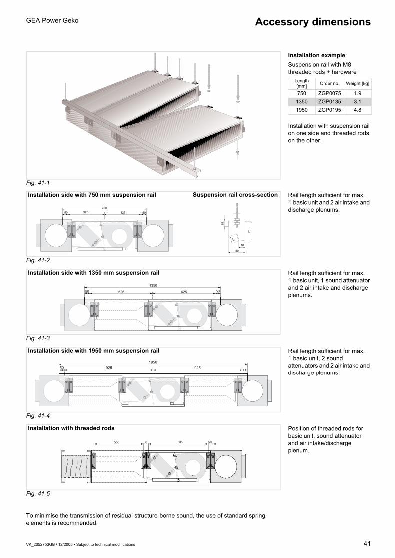
VK_2052753GB / 12/2005 • Subject to technical modifications 41
GEA Power Geko Accessory dimensions
Fig. 41-1
Fig. 41-2
Fig. 41-3
Fig. 41-4
Fig. 41-5
To minimise the transmission of residual structure-borne sound, the use of standard spring elements is recommended.
Installation example:Suspension rail with M8 threaded rods + hardware
Installation with suspension rail on one side and threaded rods on the other.
Length[mm] Order no. Weight [kg]
750 ZGP0075 1.91350 ZGP0135 3.11950 ZGP0195 4.8
750
325 5032550
15
70
24
18
50
Installation side with 750 mm suspension rail Suspension rail cross-section Rail length sufficient for max. 1 basic unit and 2 air intake and discharge plenums.
1350
62550 50625
Installation side with 1350 mm suspension rail Rail length sufficient for max. 1 basic unit, 1 sound attenuator and 2 air intake and discharge plenums.
195092550 925
Installation side with 1950 mm suspension rail Rail length sufficient for max. 1 basic unit, 2 sound attenuators and 2 air intake and discharge plenums.
50550 50 535
Installation with threaded rods Position of threaded rods for basic unit, sound attenuator and air intake/discharge plenum.

42 VK_2052753GB / 12/2005 • Subject to technical modifications
GEA Power Geko
On/off control mode On/off control mode
Fig. 42-5Temperature which is obtained in room with on/off control mode.
Fig. 42-6Temperature which is obtained in medium with on/off control mode at air outlet.
Fig. 42-1 (on/off control mode)
Fig. 42-7The valve is either open or shut.
Fig. 42-8Set command for valve.
+ = valve “open”0 = valve “closed”
Fig. 42-2 (on/off control mode)
Modulating control mode Modulating control mode
Fig. 42-9Temperature which is obtained in room with modulating control mode.
Fig. 42-10Temperature which is obtained in medium with modulating control mode at air outlet.
Fig. 42-3 (modulating control mode)
Fig. 42-11The valve setting corresponds in percent to mass flow (0 . . .100 %).
Fig. 42-12Set command for valve.
+ = valve direction “open”- = valve direction “closed”
Fig. 42-4 (modulating control mode)
V
AB
M
R AB
3-way valve
Fig. 42-5
Fig. 42-6
Warmer
Set point
Cooler
Warmer
Set point
Cooler
V
M
R
2-way valve
Fig. 42-7
Fig. 42-8
+
0
Performance viewed over time
V
AB
M
R AB
3-way valve
GEA Fig. 42-9
Fig. 42-10
Warmer
Set point
Cooler
Warmer
Set point
Cooler
V
M
R
2-way valve
GEA
Fig. 42-11
Fig. 42-12
+
Performance viewed over time
–0
Control behaviour of valves

VK_2052753GB / 12/2005 • Subject to technical modifications 43
GEA Power Geko
The following selection table presents all available valve equipment variants with the main features and compatible standard equipment.
The following symbols are used:“ ” = Valve type compatible with the corresponding operator
panelor electrical equipment.
“–” = Valve type not compatible with the corresponding operator panel or electrical equipment.
Valve type Function type
Control type
Voltage Compatible standard equipment Control system
by others
Catalogue page
MATRIX2000
MATRIX3000
MATRIX4000
Thermostat switch
R
Modulating 230 V ~
(2-pipesystem only)
–
44
N
Modulating 24 V ~
(2-pipesystem only; transformer
to be provided by
others)
(transformerto be
provided by others)
(transformerto be
provided by others)
–
45
C
Modulating
(2 volt.-free auxiliary switches)
230 V ~
(2-pipe system only)
–
46
T
On/off 230 V ~
47
Q
On/off 24 V ~
(transformerto be
provided by others)
(transformerto be
provided by others)
(transformerto be
provided by others)
–
48
S
Continuous 24 V ~(Analogue
signal 0..10 V)
– – – –
49
AB AB
AB AB
AB A
B
AB AB
AB AB
AB AB
Overview of valvesSelection table

44 VK_2052753GB / 12/2005 • Subject to technical modifications
GEA Power Geko
2- and 3-way valves with modulating actuator for upstream control (modulating control mode).Connecting cable, plastic motor casing, brass (G 1/2"A) / gunmetal (G 3/4"A) valve body, stainless-steel spindle and cone.Technical data:Nominal pressure: 16 barMax. perm. ambient temperature: 60 °CMax. inlet temperature: 110 °COperating voltage 230 V~/50/60 HzPower consumption: 7 VAProtection class: IP 43Running time: 120 s at 50 Hz (100 s at 60 Hz)Water with maximum 50 % glycol permissible.Do not fit actuator upside down!
The control valves can be supplied either loose or fitted at the manufacturer's, i.e. piped and wired. Cap nuts with soldering sleeves for Cu pipes are additionally supplied with valves fitted at the manufacturer's.Order no.
With factory-fitted valve equipment for a 4-pipe system, the order no. needs to be supplemented by the reference number for the kvs value of the heating valve, e.g. VR31610.0P (compare unit type code, page 63).Note:The maximum pressure loss in the heat exchanger with a fully opened valve should not exceed 25 kPa in cooling mode and 20 kPa in heating mode!
40~
92
56 (66)
100
AB A
B
V
AB
M
R AB
3-way valve
Measurements for G 3/4" in brackets
56 (66)
~ 92
100
V
M
R
2-way valve
Measurements for G 3/4" in brackets
Valve connected valueskvs value
[m3/h]∆pmax.
1)
[kPa]Valve ext.
thread0.25 1600 / 8002) G 1/2" A0.40 1600 / 8002) G 1/2" A0.63 1600 / 8002) G 1/2" A1.0 1200 / 2502) G 1/2" A1.6 1200 / 2502) G 1/2" A2.5 400 / 1002) G 3/4" A4.0 400 / 1002) G 3/4" A
1) Max. permissible pressure difference at which the valve still shuts against the pressure (for 2-way valves)
2) For 3-way valves
∆
! "#
Water flow rate V [l/h]
P
ress
ure
drop
∆p
[kP
a]
•
kvs value
Loose valves Factory-fittedvalve equipment
2-way 3-way 2-way 3-way0.25 935.421 935.411 VR203.0P VR303.0P0.40 935.422 935.412 VR204.0P VR304.0P0.63 935.423 935.413 VR206.0P VR306.0P1.00 935.424 935.414 VR210.0P VR310.0P1.60 935.425 935.415 VR216.0P VR316.0P2.50 935.426 935.416 VR225.0P VR325.0P4.00 935.427 935.417 VR240.0P VR340.0P
Overview of valvesValves (loose) with modulating actuators (230 V~) / modulating control mode
Fig. 44-3
Fig. 44-2
Fig. 44-1

VK_2052753GB / 12/2005 • Subject to technical modifications 45
GEA Power Geko Overview of valvesValves (loose) with modulating actuators (24 V~) / modulating control mode
2- and 3-way valves with modulating actuator for upstream control (modulating control mode).Connecting cable, plastic motor casing, brass (G 1/2"A) / gunmetal (G 3/4" A) valve body, stainless-steel spindle and cone.Technical data:Nominal pressure: 16 barMax. perm. ambient temperature: 60 °CMax. inlet temperature: 110 °COperating voltage: 230 V~/50/60 HzPower consumption: 0.7 VAProtection class: IP 43Running time: 150 s at 50 Hz (125 s at 60 Hz)Water with maximum 50 % glycol permissible.Do not fit actuator upside down!
The control valves can be supplied either loose or fitted at the manufacturer's, i.e. piped and wired. Cap nuts with soldering sleeves for Cu pipes are additionally supplied with valves fitted at the manufacturer's.Order no.
With factory-fitted valve equipment for a 4-pipe system, the order no. needs to be supplemented by the reference number for the kvs value of the heating valve, e.g. VN31610.0P (compare unit type code page 63).Note:The maximum pressure loss in the heat exchanger with a fully opened valve should not exceed 25 kPa in cooling mode and 20 kPa in heating mode.
56 (66)
4088
AB AB
82 3-way valve
V
AB
M
R AB
Measurements for G 3/4" in brackets
56 (66)
88
82 2-way valve
V
M
R
Measurements for G 3/4" in brackets
Valve connected valueskvs value
[m3/h]∆pmax. [kPa]
Valve ext.thread
0.25 16001) / 8002) G 1/2" A0.40 16001) / 8002) G 1/2" A0.63 16001) / 8002) G 1/2" A1.00 12001) / 2502) G 1/2" A1.60 12001) / 2502) G 1/2" A2.50 4001) / 1002) G 3/4" A4.00 4001) / 1002) G 3/4" A
1) Max. permissible pressure difference at which the valve still shuts against the pressure (for 2-way valves)
2) For 3-way valves
∆
! "#
Water flow rate V [l/h]
P
ress
ure
drop
∆p
[kP
a]
•
kvs value
Loose valves Factory-fittedvalve equipment
2-way 3-way 2-way 3-way0.25 935.441 935.431 VN203.0P VN303.0P0.40 935.442 935.432 VN204.0P VN304.0P0.63 935.443 935.433 VN206.0P VN306.0P1.00 935.444 935.434 VN210.0P VN310.0P1.60 935.445 935.435 VN216.0P VN316.0P2.50 935.446 935.436 VN225.0P VN325.0P4.00 935.447 935.437 VN240.0P VN340.0P
Fig. 45-3
Fig. 45-2
Fig. 45-1

46 VK_2052753GB / 12/2005 • Subject to technical modifications
GEA Power GekoOverview of valvesValves with mod. actuator (230 V~) and 2 volt.-free auxiliary switches / modulating control mode
2- and 3-way valves with modulating actuator for upstream control (modulating control mode).Connecting cable, plastic motor casing, brass (G 1/2"A) / gunmetal (G 3/4" A) valve body, stainless-steel spindle and cone.Potential-free auxiliary switches:Switch S1 (signals valve 100 % open),Switch S2 (signals valve position
0..100 % adjustable)Technical data:Nominal pressure: 16 barMax. perm. ambient temperature: 60 °CMax. inlet temperature: 110 °COperating voltage: 230 V~/50/60 HzPower consumption: 7 VAProtection class: IP 43Running time: 150 s at 50 Hz (125 s at 60 Hz)Load capacity of auxiliary switches: max. 5(1) A/250 V
max. 100 mA/24 VWater with maximum 50 % glycol permissible.Do not fit actuator upside down!
The control valves can be supplied either loose or fitted at the manufacturer's, i.e. piped and wired. Cap nuts with soldering sleeves for Cu pipes are additionally supplied with valves fitted at the manufacturer's.Order no.
With factory-fitted valve equipment for a 4-pipe system, the order no. needs to be supplemented by the reference number for the kvs value of the heating valve, e.g. VC31610.0P (compare unit type code page 63).Note: The maximum pressure loss in the heat exchanger with a fully opened valve should not exceed 25 kPa in cooling mode and 20 kPa in heating mode.
AB A
B
56 (66)
40~
116,
5
109 3-way valve
V
AB
M
R AB
Measurements for G 3/4" in brackets
Valve connected valueskvs value
[m3/h]∆pmax. [kPa]
Valve ext.thread
0.25 16001) / 8002) G 1/2" A0.40 16001) / 8002) G 1/2" A0.63 16001) / 8002) G 1/2" A1.00 12001) / 2502) G 1/2" A1.60 12001) / 2502) G 1/2" A2.50 4001) / 1002) G 3/4" A4.00 4001) / 1002) G 3/4" A
1) Max. permissible pressure difference at which the valve still shuts against the pressure (for 2-way valves)
2) For 3-way valves
kvs value
Loose valves Factory-fittedvalve equipment
2-way 3-way 2-way 3-way0.25 935.491 935.481 VC203.0P VC303.0P0.40 935.492 935.482 VC204.0P VC304.0P0.63 935.493 935.483 VC206.0P VC306.0P1.00 935.494 935.484 VC210.0P VC310.0P1.60 935.495 935.485 VC216.0P VC316.0P2.50 935.496 935.486 VC225.0P VC325.0P4.00 935.497 935.487 VC240.0P VC340.0P
56 (66)
~ 11
6,5
109 2-way valve
V
M
R
Measurements for G 3/4" in brackets
∆
! "#
Water flow rate V [l/h]
P
ress
ure
drop
∆p
[kP
a]
•
Fig. 46-3
Fig. 46-2
Fig. 46-1

VK_2052753GB / 12/2005 • Subject to technical modifications 47
GEA Power Geko Overview of valvesValves with thermoelectric actuators (230 V~) / on/off control mode
2- and 3-way valves with thermoelectric actuator for upstream control (on/off control mode).Plastic connecting cable and motor casing, gunmetal valve body, stainless-steel spindle and cone.Technical data:Nominal pressure: 16 barMax. perm. ambient temperature: 50 °CMax. inlet temperature: 110 °COperating voltage: 230 V~/50/60 HzStarting current 0.3 AOperating current 0.013 APower consumption: 3 VAProtection class: IP 43Running time: approx. 3 minWater with maximum 50 % glycol permissible.Do not fit actuator upside down!
The control valves can be supplied either loose or fitted at the manufacturer's, i.e. piped and wired. Cap nuts with soldering sleeves for Cu pipes are additionally supplied with valves fitted at the manufacturer's.Order no.
With factory-fitted valve equipment for a 4-pipe system, the order no. needs to be supplemented by the reference number for the kvs value of the heating valve, e.g. VT32516.0P (compare unit type code page 63).Note:The maximum pressure loss in the heat exchanger with a fully opened valve should not exceed 25 kPa in cooling mode and 20 kPa in heating mode.
AB AB
56 (66)
40~
92
42 3-way valve
V
AB
M
R AB
Measurements for G 3/4" in brackets
~ 92
56 (66)
42 2-way valve
V
M
R
Measurements for G 3/4" in brackets
Valve connected valueskvs value
[m3/h]∆pmax. [kPa]
Valve ext.thread
1.60 2001) / 1502) G 1/2" A2.50 2001) / 502) G 3/4" A
1) Max. permissible pressure difference at which the valve still shuts against the pressure (for 2-way valves)
2) For 3-way valves
∆
!"#$
P
ress
ure
drop
∆p
[kP
a]
• Water flow rate VW [l/h]
•
kvs value
Loose valves Factory-fittedvalve equipment
2-way 3-way 2-way 3-way1.60 935.463 935.353 VT216.0P VT316.0P2.50 935.464 935.354 VT225.0P VT325.0P
Fig. 47-3
Fig. 47-2
Fig. 47-1

48 VK_2052753GB / 12/2005 • Subject to technical modifications
GEA Power GekoOverview of valvesValves with thermoelectric actuators (24 V~) / on/off control mode
2- and 3-way valves with thermoelectric actuator for upstream control (on/off control mode).Plastic connecting cable and motor casing, gunmetal valve body, stainless-steel spindle and cone.Technical data:Nominal pressure: 16 barMax. perm. ambient temperature: 50 °CMax. inlet temperature: 110 °COperating voltage: 24 V~/50/60 HzStarting current: 0.6 AOperating current: 0.09APower consumption: 3 VAProtection class: IP 43Running time: approx. 3 minWater with maximum 50 % glycol permissible.Do not fit actuator upside down!
The control valves can be supplied either loose or fitted at the manufacturer's, i.e. piped and wired. Cap nuts with soldering sleeves for Cu pipes are additionally supplied with valves fitted at the manufacturer's.Order no.
With factory-fitted valve equipment for a 4-pipe system, the order no. needs to be supplemented by the reference number for the kvs value of the heating valve, e.g. VQ32516.0P (compare unit type code page 63).Note:The maximum pressure loss in the heat exchanger with a fully opened valve should not exceed 25 kPa in cooling mode and 20 kPa in heating mode.
3-way valve
AB AB
56 (66)
40~
92
42
V
AB
M
R AB
Measurements for G 3/4" in brackets
2-way valve
~ 92
56 (66)
42
V
M
R
Measurements for G 3/4" in brackets
Valve connected valueskvs value
[m3/h]∆pmax. [kPa]
Valve ext.thread
1.60 2001) / 1502) G 1/2" A2.50 2001) / 502) G 3/4" A
1) Max. permissible pressure difference at which the valve still shuts against the pressure (for 2-way valves)
2) For 3-way valves
∆
!"#$
P
ress
ure
drop
∆p
[kP
a]
Water flow rate VW [l/h] •
kvs value
Loose valves Factory-fittedvalve equipment
2-way 3-way 2-way 3-way1.60 935.383 935.373 VQ216.0P VQ316.0P2.50 935.384 935.374 VQ225.0P VQ325.0P
Fig. 48-3
Fig. 48-2
Fig. 48-1

VK_2052753GB / 12/2005 • Subject to technical modifications 49
GEA Power Geko Overview of valvesValves with continuous actuator (24 V~, 0..10 V)
2- and 3-way valves with constant actuator for upstream control.Plastic connecting cable and motor casing, brass (G 1/2" A) / gunmetal (G 3⁄4" A) valve body, stainless-steel spindle and cone.Technical data:Nominal pressure: 16 barMax. perm. ambient temperature: 55 °CMax. inlet temperature: 110 °COperating voltage: 230 V~/50/60 HzAnalogue control signal: 0..10 (2..10) VPower consumption: 1.4 VAProtection class: IP 40Running time: 150 s at 50 Hz (125 s at 60 Hz)Water with maximum 50 % glycol permissible. Do not fit actuator upside down!
The control valves can be supplied either loose or fitted at the manufacturer's, i.e. piped and wired. Cap nuts with soldering sleeves for Cu pipes are additionally supplied with valves fitted at the manufacturer's.Order no.
With factory-fitted valve equipment for a 4-pipe system, the order no. needs to be supplemented by the reference number for the kvs value of the heating valve, e.g. VS31610.0P (compare unit type code page 63).Note:The maximum pressure loss in the heat exchanger with a fully opened valve should not exceed 25 kPa in cooling mode and 20 kPa in heating mode.
AB AB
56 (66)
40~
92
100 3-way valve
V
AB
M
R AB
Measurements for G 3/4" in brackets
56 (66)
~ 92
100 2-way valve
V
M
R
Measurements for G 3/4" in brackets
Valve connected valueskvs value
[m3/h]∆pmax.
1)
[kPa]Valve ext.
thread0.25 16001) / 8002) G 1/2" A0.40 16001) / 8002) G 1/2" A0.63 16001) / 8002) G 1/2" A1.00 12001) / 2502) G 1/2" A1.60 12001) / 2502) G 1/2" A2.50 4001) / 1002) G 3/4" A4.00 4001) / 1002) G 3/4" A
1) Max. permissible pressure difference at which the valve still shuts against the pressure (for 2-way valves)
2) For 3-way valves
∆
! "#
Water flow rate V [l/h]
P
ress
ure
drop
∆p
[kP
a]
•
kvs value
Loose valves Factory-fittedvalve equipment
2-way 3-way 2-way 3-way0.25 935.611 935.601 VS203.0P VS303.0P0.40 935.612 935.602 VS204.0P VS304.0P0.63 935.613 935.603 VS206.0P VS306.0P1.00 935.614 935.604 VS210.0P VS310.0P1.60 935.615 935.605 VS216.0P VS316.0P2.50 935.616 935.606 VS225.0P VS325.0P4.00 935.617 935.607 VS240.0P VS340.0P
Fig. 49-3
Fig. 49-2
Fig. 49-1

50 VK_2052753GB / 12/2005 • Subject to technical modifications
GEA Power Geko
The required medium flow rate is set in accordance with the opposite flow diagrams.The pre-setting corresponds to the number of turns to the left of the setting screw from the right stop position (valve closed).
All GEA valve equipment is optionally available with water inlet and outlet shut-off valves.These both shut off the cooling or heating medium and also regulate and balance the medium flow. Depending on the nominal size of the control valve, shut-off valves with a kvs value of 1.45 or 2.20 are used.
Technical data:Nominal pressure 10 barMax. inlet temperature: 130 °CpH value: 8-9.5Water with max. 50 % glycol is permissible as the medium
The shut-off valves are supplied as standard with cap nuts and flat sealing inserts (soldered fitting):
SW24
66
3/4"
3/4"
33
kvs value 1.45
kvs value 2.20
Connection
Control valve Shut-off valve
kvs values Connection thread kvs values Connection
thread
Soldered fitting for Cu pipe
0.25-1.60 G 1/2" A 1.45 G 3/4" A Ø 152.50-4.00 G 3/4" A 2.20 G 3/4" A Ø 15
Overview of valvesShut-off valves
Fig. 50-1

VK_2052753GB / 12/2005 • Subject to technical modifications 51
GEA Power Geko
Shut-off valves
Pre-setting 1/4 1/2 1 1 1/2 2 3 4 5 6 7 8kv values 0.07 0.13 0.22 0.32 0.43 0.65 0.85 1.10 1.25 1.40 1.45
P
ress
ure
drop
∆p
[kP
a]
Water flow rate mW [kg/h]•
Pre-settingkvs value 1.45
Pre-setting 1/2 1 1 1/2 2 2 1/2 3 4 5kv values 0.2 0.4 0.6 1.0 1.5 1.7 2.0 2.2
P
ress
ure
drop
∆p
[kP
a]
Water flow rate mW [kg/h]•
Pre-settingkvs value 2.20

52 VK_2052753GB / 12/2005 • Subject to technical modifications
GEA Power Geko
Fig. 52.1
Terminal box with connections for Geko components.Basic unit order code
Plastic terminal box GPxx.xxxx.AxxGPxx.xxxx.BxxGPxx.xxxx.CxxGPxx.xxxx.DxxGPxx.xxxx.FxxGPxx.xxxx.GxxGPxx.xxxx.Hxx
For connection to a controller, all components such as fan(s), valve(s) and optional sensors are wired in a terminal box.
Depending on the unit application and valve equipment, the terminal box is supplied in plastic or sheet steel. Selection is made via the unit’s type code as illustrated in the adjacent figure.
Additional integrated sensors wired to the terminal strip should be ordered separately.The following table shows the possible options.
Sheet-steel electrical control
box
GPxx.xxxx.KxxGPxx.xxxx.LxxGPxx.xxxx.MxxGPxx.xxxx.NxxGPxx.xxxx.PxxGPxx.xxxx.QxxGPxx.xxxx.Rxx
Optional sensor equipment Return air sensor Supply air sensor
Plastic terminal box or sheet-steel electrical control box
• 1• 2• • 3
D 0 . 0 0 . Z ZOrder code
N
110
111
112
113
114
115
116N
60 61 874
875
876
877
878
10 11 12 13
M~
879
M~
N N
M1~
TK
*
TK
*
Example of unit connection diagram
Fan Cooling valve Heating valve
Supplyair
sensor
Returnair
sensor
Only one fan speed stage may be activated at once.
* with thermal contacts with external leads
Stag
e 1
Stag
e 2
Stag
e 3
Stag
e 4
Stag
e 5
Stag
e 6
Stag
e 7
Ope
n
Clos
ed
Ope
n
Clos
ed
Control system by others

VK_2052753GB / 12/2005 • Subject to technical modifications 53
GEA Power Geko GEA MATRIX® control systemSystem description
Overview figure
MATRIX 2000The MATRIX 2000 control system supports all basic functions (heating / cooling) of the recirculation air Power Geko. The controller can be integrated into the following system types:– 2-pipe “heating only” systems– 2-pipe “cooling only” systems– 2-pipe “heating or cooling” systems (change-over)– 4-pipe “heating and cooling” systemsThe fan is controlled in three speeds automatically depending on the deviation between set point and actual temperature. The speed can be set manually and the unit switched off (with frost protection) via the operator panel. Valves with on/off or modulating control behaviour and a supply voltage of 24 V or 230 VAC can be activated to control the heating and/or cooling capacity. This does not include 4-pipe systems – in this case, only on/off actuators can be used. Additionally, the MATRIX 2000 enables monitoring of the fan motor via thermal contacts with external leads and also of the condensation water level on cooling units with condensate pump.The OP21 operator panel enables the set point values to be set quickly and easily without extensive prior experience. Mechanical limit stops can be used to limit the setting range for the set point temperature and fan speed. Room temperature is measured via a sensor integrated in the operator panel. If the operator panel is positioned in an unfavourable location (such as by the door), an external temperature sensor or return air sensor can be connected (not possible on change-over systems). System faults are signalled centrally via the red “malfunction” LED. If energy saving mode is activated, this is displayed via the yellow LED integrated into the button.In addition to protection class IP20 (OP21 C), an IP54 operator panel variant (OP21 I) is available for moist areas, for instance.The connection in the unit is made via plug-in cage clamps. Electronics, fans and valves (230 V) are fused separately via two microfuses on the power unit. A pre-fuse of B 10 A should be supplied for the required circuit protection.
The MATRIX 2000 can be used for controlling stand-alone recirculation air units and also recirculation air unit groups. The integrated GEA MATRIX.Net bus system enables several groups to be combined to form a network consisting of up to 16 groups. This also enables combination with the MATRIX 3000 / 4000 controllers and the connection of global modules and communication interfaces.
Actuator type valves
On/off Modulating
•
• •
• •
• •
LEDs for operation / malfunction / ext. influence
Set point temperature switch
Normal / energy saving mode switch
Fan speed selection switch
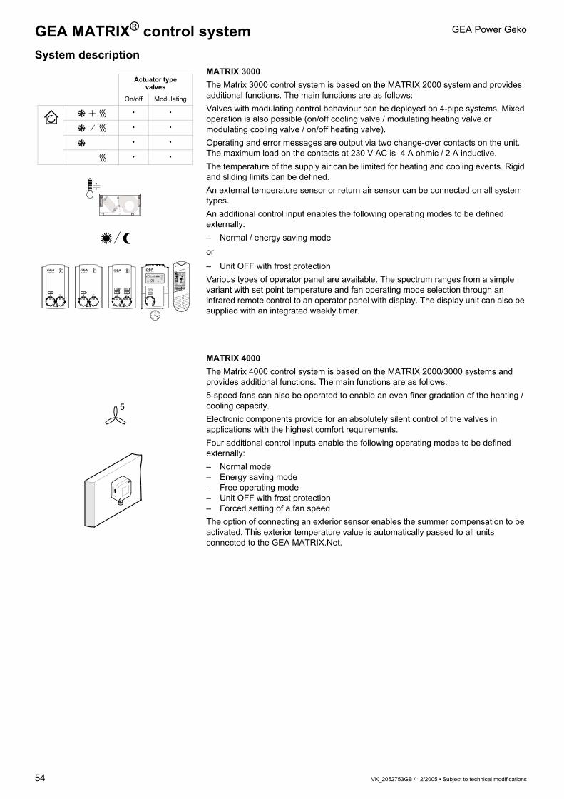
54 VK_2052753GB / 12/2005 • Subject to technical modifications
GEA Power GekoGEA MATRIX® control systemSystem description
MATRIX 3000The Matrix 3000 control system is based on the MATRIX 2000 system and provides additional functions. The main functions are as follows:Valves with modulating control behaviour can be deployed on 4-pipe systems. Mixed operation is also possible (on/off cooling valve / modulating heating valve or modulating cooling valve / on/off heating valve). Operating and error messages are output via two change-over contacts on the unit. The maximum load on the contacts at 230 V AC is 4 A ohmic / 2 A inductive.The temperature of the supply air can be limited for heating and cooling events. Rigid and sliding limits can be defined.An external temperature sensor or return air sensor can be connected on all system types.An additional control input enables the following operating modes to be defined externally:– Normal / energy saving mode
or
– Unit OFF with frost protectionVarious types of operator panel are available. The spectrum ranges from a simple variant with set point temperature and fan operating mode selection through an infrared remote control to an operator panel with display. The display unit can also be supplied with an integrated weekly timer.
MATRIX 4000The Matrix 4000 control system is based on the MATRIX 2000/3000 systems and provides additional functions. The main functions are as follows:5-speed fans can also be operated to enable an even finer gradation of the heating / cooling capacity.Electronic components provide for an absolutely silent control of the valves in applications with the highest comfort requirements.Four additional control inputs enable the following operating modes to be defined externally:– Normal mode– Energy saving mode– Free operating mode– Unit OFF with frost protection– Forced setting of a fan speedThe option of connecting an exterior sensor enables the summer compensation to be activated. This exterior temperature value is automatically passed to all units connected to the GEA MATRIX.Net.
21 . 5° C
100 14:08R E
on off
funcsend
- +
%
Actuator type valves
On/off Modulating
• •
• •
• •
• •
5

VK_2052753GB / 12/2005 • Subject to technical modifications 55
GEA Power Geko GEA MATRIX® control systemOverview of performance features
Performance features MATRIX 2000
MATRIX 3000
MATRIX 4000
Unit type 2-pipe “heating only” systems
2-pipe “cooling only” systems
2-pipe “heating or cooling” systems
4-pipe “heating and cooling” systems
Fan Up to 3 speeds (1 x 230 V)
Up to 5 speeds (1 x 230 V)
Temperature-dependent fan control
Motor monitoring with thermal contact with external leads
Valve control 1 x on/off; 1 x modulating; 2 x on/off
1 x on/off; 1 x modulating; 2 x on/off; 2 x modulating
Via semiconductor
External heating valve on coolers with fan switch-off
Frost protection Room frost protection
Summer / winter compensation *
Supply air temperature limitation
Min. / max. limitation – heating
Min. limitation – cooling
Control inputs Energy saving mode or gate/window contact *
Energy saving mode or gate/window contact, unit OFF, free operating mode * *
Exterior temperature measurement
Via local sensor connection
Via GEA MATRIX.AI
Inlet temperature measurement Via local sensor connection
Return air temperature measurement
Via local sensor connection **
Supply air temperature measurement
Via local sensor connection
Messages Condensate level alarm with unit switch-off
Heating and/or cooling request
Operation message via change-over contact
Error message via change-over contact
Control types Room temperature control
Supply air temperature control
Cascade room supply air temperature cont. / displacement ventilation
Cooling cover / convector heater
GEA MATRIX.Net bus systemExtendible with: GEA MATRIX.DI
GEA MATRIX.AI
GEA MATRIX.DO
GEA MATRIX.Clock
GEA MATRIX.LON
GEA MATRIX.WEB
Service tools GEA MATRIX.PDA
GEA MATRIX.PC
Control units GEA MATRIX OP21x
GEA MATRIX OP30x
GEA MATRIX OP31x
GEA MATRIX OP44x
GEA MATRIX OP50x / 51x
* with additional module only** not with heating or cooling units

56 VK_2052753GB / 12/2005 • Subject to technical modifications
GEA Power GekoGEA MATRIX® control systemFitting the operator panels
Due to the fact that the operator panel is split into two units, the cover only needs to be clipped on to the mounting plate during commissioning. This provides optimum protection against dirt and damage for the operator panels during the construction phase.
The cable connection is made via cage clamps. This enables solid and flexible cores to be used quickly and easily.
To mount the operator panel on a standard in-wall socket, corresponding drill-holes are provided in the mounting plate.
The operator panel can also be fitted directly onto the wall (cable laid under plaster or in cavity wall).
IP54 operator panels for moisture proof applications are available on request.
To prevent dirt accumulation or accidental operation, operator panel covers are available as accessories (see “Fig. 57-4“ on page 57).
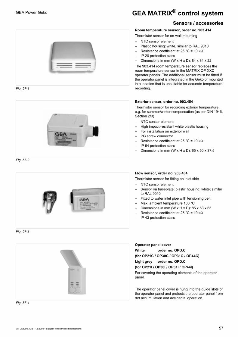
VK_2052753GB / 12/2005 • Subject to technical modifications 57
GEA Power Geko
Room temperature sensor, order no. 903.414Thermistor sensor for on-wall mounting– NTC sensor element– Plastic housing: white, similar to RAL 9010– Resistance coefficient at 25 °C = 10 kΩ– IP 20 protection class– Dimensions in mm (W x H x D): 84 x 84 x 22The 903.414 room temperature sensor replaces the room temperature sensor in the MATRIX OP XXC operator panels. The additional sensor must be fitted if the operator panel is integrated in the Geko or mounted in a location that is unsuitable for accurate temperature recording.
Exterior sensor, order no. 903.454Thermistor sensor for recording exterior temperature, e.g. for summer/winter compensation (as per DIN 1946, Section 2/3)– NTC sensor element– High impact-resistant white plastic housing– For installation on exterior wall– PG screw connector– Resistance coefficient at 25 °C = 10 kΩ– IP 54 protection class– Dimensions in mm (W x H x D): 65 x 50 x 37.5
Flow sensor, order no. 903.434Thermistor sensor for fitting on inlet side– NTC sensor element– Sensor on baseplate; plastic housing; white; similar
to RAL 9010– Fitted to water inlet pipe with tensioning belt– Max. ambient temperature 100 °C– Dimensions in mm (W x H x D): 85 x 53 x 65– Resistance coefficient at 25 °C = 10 kΩ– IP 43 protection class
Operator panel coverWhite order no. OPD.C(for OP21C / OP30C / OP31C / OP44C)Light grey order no. OPD.C(for OP21I / OP30I / OP31I / OP44I)For covering the operating elements of the operator panel.
The operator panel cover is hung into the guide slots of the operator panel and protects the operator panel from dirt accumulation and accidental operation.
GEA MATRIX® control systemSensors / accessories
Fig. 57-3
Fig. 57-2
Fig. 57-1
Fig. 57-4

58 VK_2052753GB / 12/2005 • Subject to technical modifications
GEA Power GekoGEA MATRIX® control systemGlobal modules
MATRIX.DI digital input moduleThe MATRIX.DI digital input module belongs to the global modules of the GEA MATRIX control system and is used for receiving digital control signals. It thus enables the control system to be influenced by external systems. The module can be integrated into the MATRIX network at any point. A maximum of two MATRIX.DI modules may be operated in the same network at any time. The module has eight independent digital inputs that are controlled via voltage-free contacts. LEDs display the current input status. Commands entered via the DI module have priority over the settings of the local operating unit. The following functions and operating modes can be defined via the module:– HVAC mode (heating / cooling / automatic)– Normal / energy saving mode– Fan speed (1/2/3/4/5/Auto/Mute)– Activate mixed-air operation– Unit off with frost protection– Activate controller operating valuesThe module is shipped with a configuration preset at the manufacturer's. Different configurations can be set via the MATRIX.PC service software. The function allocation of the inputs and the respective allocation to the group(s) can be freely selected.
Technical data:
Configuration preset at the manufacturer's:
Power supply 24V DC ± 15 %Protection class IP 20Max. current consumption 0.01 ADimensions 106 mm x 90 mm x 58 mmOperating temperature 0 to +45 °CFusing 10 A TMounting Mounting rail
Input Valid for Closed contact means:1 All groups HVAC mode – heating2 All groups HVAC mode – cooling3 All groups Normal mode4 All groups Energy saving mode5 Group 0 Fan in stage 36 – –7 – –8 Group 0 Mixed-air operation active

VK_2052753GB / 12/2005 • Subject to technical modifications 59
GEA Power Geko GEA MATRIX® control systemGlobal modules
MATRIX.DO digital output moduleThe MATRIX.DO digital output module belongs to the global modules of the MATRIX control systems and is used for outputting signals from the MATRIX system. It enables messages and operating statuses to be relayed to external systems. The module can be integrated into the MATRIX network at any point. A maximum of two MATRIX.DO modules may be operated in the same network at any time. The module has eight separate digital outputs with voltage-free change-over contacts. LEDs display the current output status. Messages and operating statuses of the system components of one or more groups can be output directly or in conjunction with further operating statuses. Compare functions, arithmetic functions or time functions and others are available for this.The following messages / operating modes can be output amongst others:– Error messages (e.g. motor overheating, risk of frost, sensor error, condensate
level too high)– Current fan speed– Normal mode / energy saving mode– Bypass mode– Current HVAC mode (heating / cooling / automatic)– Mixed-air / recirculation air operation– Electrical heating active– X number of units are in heating or cooling modeThe module is shipped with a configuration preset at the manufacturer's. Different configurations can be set via the MATRIX.PC service software. The function allocation of the outputs and the respective allocation to the group(s) can be freely selected.
Technical data:
Configuration preset at the manufacturer's:
Power supply 24 V DC ± 15 %Protection class IP 20Max. nominal current consumption 0.14 ADimensions 160 mm x 90 mm x 58 mmOperating temperature 0 to +45 °CFusing 10 A TMounting Mounting railContact load 250 V / 5 A (ohmic); 2 A (inductive)
Input Valid for Energised relay signals:1 All groups Operation2 All groups Error message3 All groups Frost message4 Group 0 Error message5 Group 1 Error message6 Group 2 Error message7 Group 3 Error message8 Group 4 Error message
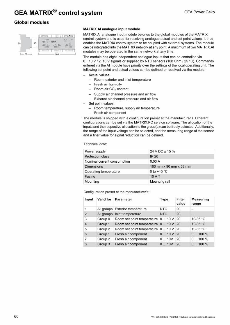
60 VK_2052753GB / 12/2005 • Subject to technical modifications
GEA Power GekoGEA MATRIX® control systemGlobal modules
MATRIX.AI analogue input moduleMATRIX.AI analogue input module belongs to the global modules of the MATRIX control system and is used for receiving analogue actual and set point values. It thus enables the MATRIX control system to be coupled with external systems. The module can be integrated into the MATRIX network at any point. A maximum of two MATRIX.AI modules may be operated in the same network at any time. The module has eight independent analogue inputs that can be controlled via 0…10 V / 2..10 V signals or supplied by NTC sensors (10k Ohm / 25 °C). Commands entered via the AI module have priority over the settings of the local operating unit. The following set point and actual values can be defined or received via the module:– Actual values:
– Room, exterior and inlet temperature– Fresh air humidity– Room air CO2 content– Supply air channel pressure and air flow– Exhaust air channel pressure and air flow
– Set point values:– Room temperature, supply air temperature– Fresh air component
The module is shipped with a configuration preset at the manufacturer's. Different configurations can be set via the MATRIX.PC service software. The allocation of the inputs and the respective allocation to the group(s) can be freely selected. Additionally, the range of the input voltage can be selected, and the measuring range of the sensor and a filter value for signal reduction can be defined.
Technical data:
Configuration preset at the manufacturer's:
Power supply 24 V DC ± 15 %Protection class IP 20Nominal current consumption 0.03 ADimensions 160 mm x 90 mm x 58 mmOperating temperature 0 to +45 °CFusing 10 A TMounting Mounting rail
Input Valid for Parameter Type Filter value
Measuring range
1 All groups Exterior temperature NTC 20 –2 All groups Inlet temperature NTC 20 –3 Group 0 Room set point temperature 0 ... 10 V 20 10-35 °C4 Group 1 Room set point temperature 0 ... 10 V 20 10-35 °C5 Group 2 Room set point temperature 0 ... 10 V 20 10-35 °C6 Group 1 Fresh air component 0 ... 10 V 20 0 ... 100 %7 Group 2 Fresh air component 0 ... 10V 20 0 ... 100 %8 Group 3 Fresh air component 0 ... 10V 20 0 ... 100 %

VK_2052753GB / 12/2005 • Subject to technical modifications 61
GEA Power Geko GEA MATRIX® control systemGlobal modules / central timer
MATRIX.LON moduleThe MATRIX.LON communication module belongs to the global modules of the GEA MATRIX control systems and is used for connecting the MATRIX control system to a network structure in accordance with the LON WORKS standard. It enables the connection of air-treatment components to a building management system or other facility management systems. It also enables external systems such as shutters or lighting systems to be controlled via the MATRIX OP50/51 operator panel. The module can be integrated into the MATRIX network at any point. A maximum of 16 MATRIX.LON modules can be deployed in any one GEA MATRIX network.
MATRIX.Clock timer moduleThe MATRIX.Clock timer module is intended for use as a central weekly timer. The module can be integrated into the MATRIX network at any point and supports up to 16 groups in a network. The groups can be assigned individually to the six weekly programmes, the special switching days and the holiday programme. In each weekly programme, up to four switching times (2 x on / 2 x off) can be defined. Additionally, up to six special switching days with up to four switching times (2 x on / 2 x off) per special switching day can be defined. Holiday periods can be defined via the holiday days that can be programmed for the whole calendar year. Input is carried out via a straightforward “push&turn” control. Ease of user navigation is ensured by means of structured menus, plain text messages and pictographs. The current status of the individual programmes is displayed via a menu. The timer module can be toggled between six different languages online. The switch between summer and winter-time is done automatically. If required, a blocking protection e.g. for pumps can be activated (once a week). Additionally, the time format can be switched between 12 and 24-hour display.Power to the clock timer is supplied via the MATRIX controller’s power unit.Two different variants are available:– MATRIX.Clock C with IP 20 protection class; colour – white (similar to RAL 9016)– MATRIX.Clock I with IP 54 protection class; colour – light grey (similar to RAL 7035)
Group 2
Group 3 Group 1
Group 4 Group 16
Technical data:
Power supply 24 V DC ± 15 %Protection class IP 20Nominal current consumption 0.03 ADimensions 106 mm x 90 mm x 58 mmOperating temperature 0 to +45 °CFusing 10 A TMounting Mounting rail

62 VK_2052753GB / 12/2005 • Subject to technical modifications
GEA Power GekoGEA MATRIX® control systemService tools
MATRIX.PDA service toolThe MATRIX.PDA service tool is used for setting the parameters of the MATRIX control system and makes the commissioning and maintenance of systems considerably easier. The service tool can be connected via the service interface that is integrated into all operator panels, controllers, global modules, the clock timer and the communication modules. Input is carried out via a straightforward “push&turn” control. The following main functions are available:– Automatic network scanning with display of users found– Plain-text error display– Modification of parameters such as temperature limits, times or control type– Display of actual values– Display of current unit status such as HVAC mode or valve position– Manual control of actuators such as fans and valves– Read out, saving and writing of configuration dataThe service tool can be toggled between six different languages online. The unit is protected from damage during transit and use via a rubber guard.
MATRIX.PC service softwareBuilding on the functions of the MATRIX.PDA service tool, the MATRIX.PC service software provides further comprehensive functions in the field of parametrisation, commissioning and data recording of the GEA MATRIX controller system.The service software can be connected via the service interface that is integrated into all operator panels, controllers, global modules, the timer and the communication modules. A USB interface is required on the PC. The enclosed adaptor establishes the necessary connection between the PC and the service interface.In addition to the functions of the MATRIX.PDA, the following main functions are also available:– Online display of module, status and network data– Recording and saving of temperature progressions and switching states of the
actuators with adjustable sample rate– Offline parameterisation– Programming of the inputs and outputs provided for this purpose
(controllers, global modules)– Output of messages and network data– Parameterisation of controller and operator panel functionality– Input of sensor correction factorsPC system requirements:– PC with 233 MHz clock speed or higher– 20 MB of free hard drive space– Minimum screen resolution of 800x600 pixels– USB interface for CAN adaptorThe software can be run on the following operating systems:Windows 98 Second Edition; Windows 2000; Windows XPIn addition to the program CD, the installation instructions and interface module for connection to the USB port of the PC are also provided.

VK_2052753GB / 12/2005 • Subject to technical modifications 63
GEA Power Geko Unit type code
Unit code Controller package Valve codeG P 1 1 . U 0 W 3 . A 0 0 D 2 . 0 0 1 . B A V R 3 1 0 1 0 . 0
Capacity stage1 = Capacity stage 12 = Capacity stage 2
Fan speedsPlastic terminal box with terminal stripA = Speed 1, 2, 3B = Speed 2, 3, 4C = Speed 3, 4, 5D = Speed 4, 5, 6F = Speed 5, 6, 7G = Speed 1, 4, 7H = Speed 1, 2, 3, 4, 5Sheet-steel electrical control box with terminal strip or for integrated controlK = Speed 1, 2, 3L = Speed 2, 3, 4M = Speed 3, 4, 5N = Speed 4, 5, 6P = Speed 5, 6, 7Q = Speed 1, 4, 7R = Speed 1, 2, 3, 4, 5
Condensate pump0 = With condensate drain1 = Via condensate pump**
Controller type0 = Terminal box2 = MATRIX 20003 = MATRIX 30004 = MATRIX 4000
Controller package no.
Operator panelIP20A = MATRIX OP21CB = MATRIX OP30CC = MATRIX OP31CD = MATRIX OP44CE = MATRIX OP50CF = MATRIX OP51CIP54G = MATRIX OP21IH = MATRIX OP30II = MATRIX OP31IK = MATRIX OP44IL = MATRIX OP50IM = MATRIX OP51IN = MATRIX.IRZ = No operator panel
Unit typeMaster unit, operator panelA = IncludedC = No operator panelSlave unitD = No operator panelUnit withZ = Terminal box
Function type2-pipe/4-pipeT = Thermoelectric (230 V, on/off)Q = Thermoelectric (24 V, on/off)R = Modulating actuator
(230 V, modulating)N = Modulating actuator
(24 V, modulating)S = Continuous motor drive
(24 V, 0-10 V analogue signal)C = Modulating actuator
(230 V, modulating) + 2 contactsCombinations (4-pipe)1 = Cooling
Heating
=
=
Thermoelectric(230 V, on/off)Modul. actuator(230 V, modulating)
2 = Cooling
Heating
=
=
Modul. actuator(230 V, modulating)Thermoelectric(230 V, on/off)
3 = Cooling
Heating
=
=
Thermoelectric(24 V, on/off)Modul. actuator(24 V, modulating)
4 = Cooling
Heating
=
=
Modul. actuator(24 V, modulating)Thermoelectric(24 V, on/off)
5 = Cooling
Heating
=
=
Modul. actuatorwith 2 auxiliary switches(230 V, modulating)Modul. actuator(230 V, modulating)
Water connection2 = 2-way (cooling), 2-way (heating)3 = 3-way (cooling), 3-way (heating)8 = 2-way (cooling), 3-way (heating)9 = 3-way (cooling), 2-way (heating)
Circuit 2 (4-pipe heating)03 = Kvs value 0.25 (R, N, S, C)04 = Kvs value 0.40 (R, N, S, C)06 = Kvs value 0.63 (R, N, S, C)10 = Kvs value 1.0 (R, N, S, C)16 = Kvs value 1.6 (R, N, S, C, T, Q)25 = Kvs value 2.5 (R, N, S, C, T, Q)40 = Kvs value 4.0 (R, N, S, C)
Circuit 1 (2-pipe cooling/heating, 4-pipe cooling)03 = Kvs value 0.25 (R, N, S, C)04 = Kvs value 0.40 (R, N, S, C)06 = Kvs value 0.63 (R, N, S, C)10 = Kvs value 1.0 (R, N, S, C)16 = Kvs value 1.6 (R, N, S, C, T, Q)25 = Kvs value 2.5 (R, N, S, C, T, Q)40 = Kvs value 4.0 (R, N, S, C)
Shut-off valve – water inlet and outlet0 = Without shut-off valves1 = With shut-off valves
Medium-flow functionHeating only0W = Warm waterCooling onlyW0 = Chilled waterCooling or heatingWC = Chilled water – Warm waterCooling and heatingHW = Chilled water – Warm water
Size1 = Size 12 = Size 23 = Size 3
Air-flow functionU = Recirculation air unit
Coil connection*Ceiling3 = Left4 = Right
Thermal contacts0 = with integrated thermal contacts1 = with thermal contacts with external leads
* Connection side from front with view of discharge** Sheet-steel electrical control box required

Customer proximity, sales structures
Reachable always and everywhere!
www.gea-air-eco2nomy.com
• S
ubje
ct t
o m
odifi
catio
n
Issu
e xx
/ xxx
x •
The complete addresses are available on the
Internet under: www.gea-air-eco2nomy.com.
S
RUS
PL
LV
LT
L
IS
GB
F
F
EST
E
DK
FIN
D
D
D
BY
CH
CZ
CZ
B
BG
BIH
GEA Klimatechnik
GmbH & Co KG
A-4673 Gaspoltshofen
Tel. +43 / 7735 / 8000-0
GEA Happel Belgium N. V.
B-1130 Brussels
Tel. +32 / 2 / 2406161
EVISS Ltd.
BG-7000 Rousse
Tel . +359 / 82 / 81000
GEA Klimatechnik
GmbH & Co KG
RS-11070 Novi Beograd
Tel. +381 / 11 / 3193955
GEA Klimatechnik UAB
LT-01141 Vilnius
Tel. +370 / 5 / 2106060
ATC Klimatec Schweiz AG
CH-3065 Bolligen-Station
Tel. +41 / 31 / 9171919
GEA LVZ, a.s.
CZ-46312 Liberec
Tel. +420 / 48 / 5225-111
GEA Klimatizace spol. s r.o.
CZ-46312 Liberec
Tel. +420 / 48 / 5225-303
GEA Happel
Klimatechnik GmbH
D-44625 Herne
Tel. +49 / 2325 / 468-00
GEA Happel
Wieland GmbH
D-44625 Herne
Tel. +49 / 2325 / 468-754
GEA Delbag
Lufttechnik GmbH
D-44625 Herne
Tel. +49 / 2325 / 468-700
GEA Delbag-Luftfilter
Vertriebsgesellschaft mbH
D-10709 Berlin
Tel. +49 / 30 / 43592-3
GEA Klimateknik ApS
DK-2610 Rødovre
Tel . +45 / 38 / 887070
GEA Air Treatment
Marketing Services Int.
GmbH – oficina España
E-28036 Madrid
Tel. +34 / 91 / 3837701
GEA Klimatechnik UAB
LT-01141 Vilnius
Tel. +370 / 5 / 2106060
GEA Delbag
Filtration d l‘air
F-77450 Montry
Tel. +33 / 1 / 60043355
GEA Happel France sarl
F-59436 Roncq Cedex
Tel. +33 / 3 / 20689020
OY TEKNOCALOR AB
FIN-01300 Vantaa
Tel. + 358 / 9 / 82546020
GEA Denco Ltd.
UK-HR4 8DS Hereford
Tel. +44 / 1432 / 277 277
GEA Klimatechnika Kft
H-1037 Budapest
Tel. +36 / 1 / 4393200
GEA Klima-rashladna
tehnika d.o.o.
HR-10000 Zagreb
Tel. +385 / 1 / 6064900
Aspect Environmental Ltd.
Ardee, Co. Louth Ireland
Tel. +353 / 41 / 6858983
Rafn Jensson
IS-110 Reykjavik
Tel. +354 / 56 / 780-30
GEA Happel Luxembourg
L-4940 Bascharage
Tel. +352 / 26 / 502970
GEA Klimatechnik UAB
LT-01141 Vilnius
Tel. +370 / 5 / 2106060
GEA Klimatechnik UAB
LT-01141 Vilnius
Tel. +370 / 5 / 2106060
GEA Klimatechnik
GmbH & Co KG
RS-110 70 Novi Beograd
Tel. +381 / 11 / 3193955
GEA Klimaprodukter AS
N-0484 Oslo
Tel. +47 / 220 / 27990
GEA Happel Nederland B.V.
NL-2909 LL
Capelle a/d Ijssel
Tel. +31 / 10 / 2350606
Nónio, Lda.
P-1269-090 Lisboa
Tel. +351 / 21 / 3826160
GEA Klimatyzacja Sp. z o.o.
PL-54610 Wroclaw
Tel. +48 / 71 / 3737952
GEA Klimatechnik s.r.l.
RO-300222 Timisoara
Tel. +40 / 356 / 423703
GEA Klimatechnik
GmbH & Co KG
RU-105094 Moskva
Tel. +7 / 495 / 9566674
GEA EXOS Ventilation AB
S-74528 Enköping
Tel. +46 / 171 / 85530
GEA Klimatizácia s.r.o.
SK-83104 Bratislava
Tel. +421 / 7 / 44457917
GEA Klimatizacijska
Tehnika d.o.o.
SI-1000 Ljubljana
Tel. +386 / 1 / 2573850
GEA Klimatechnik
GmbH & Co KG
RS-11070 Novi Beograd
Tel. +381 / 11 / 3193955
GEA ISISAN
TR-80700
Balmumcu Istanbul
Tel. +90 / 212 / 2757171
GEA Ukraina t.o.v.
UA-01135 Kyiv
Tel. +38 / 044 / 4619356
RO
SK
SLO
SRB
TR
UA
IE
HR
H
MWE
N
NL
A PD
Cop
yrig
ht G
EA A
ir Tr
eatm
ent


![109 A Must-Have For Glazing Contractors · Geko 350 PV [350kg] The Geko 350 PV is the big brother of our popular Geko 250 PV robot and boasts 350kg of lifting power for effortless](https://img.pdfslide.us/doc/110x75/60109a04eb6c0d7da25b33fc/109-a-must-have-for-glazing-contractors-geko-350-pv-350kg-the-geko-350-pv-is-the.jpg)