Embed Size (px)
Citation preview

GE Fanuc Automation
Computer Numerical Control Products
Series 15 – Model Bfor Gas, Laser, Plasma Cutting Machines
Descriptions Manual
GFZ-62082EN-1/01 March 1997

GFL-001
Warnings, Cautions, and Notesas Used in this Publication
Warning
Warning notices are used in this publication to emphasize that hazardous voltages, currents,temperatures, or other conditions that could cause personal injury exist in this equipment ormay be associated with its use.
In situations where inattention could cause either personal injury or damage to equipment, aWarning notice is used.
Caution
Caution notices are used where equipment might be damaged if care is not taken.
NoteNotes merely call attention to information that is especially significant to understanding andoperating the equipment.
This document is based on information available at the time of its publication. While effortshave been made to be accurate, the information contained herein does not purport to cover alldetails or variations in hardware or software, nor to provide for every possible contingency inconnection with installation, operation, or maintenance. Features may be described hereinwhich are not present in all hardware and software systems. GE Fanuc Automation assumesno obligation of notice to holders of this document with respect to changes subsequently made.
GE Fanuc Automation makes no representation or warranty, expressed, implied, or statutorywith respect to, and assumes no responsibility for the accuracy, completeness, sufficiency, orusefulness of the information contained herein. No warranties of merchantability or fitness forpurpose shall apply.
©Copyright 1997 GE Fanuc Automation North America, Inc.
All Rights Reserved.

PREFACE
This manual describes the following products.
I Name of series I Abbreviation I
1 FANUC Series 150MB 1 150MB I
Belated manuals
The following manuals are available for 150MB. In the table, this manual is marked with an asterisk(*).
Document Document name
number
FANUC Series 150MB B-62082EW1
(FOR GAS, LASER, PLASMA CUTTING
MACHINE)
DESCRIPTIONS
FANUC Series H-MB DESCRIPTIONS B-62082E
FANUC Series 150MODEL 3 B-62564E
For Machining Center
OPERATOR'S MANUAL
(Programming)
FANUC Series 15-MODEL B
For Machining Center
OPERATOR'S MANUAL
(Operation)
3-62564E-1
P-l

CONTENTS
PREFACE . . . . . . . . . . . . . . . . . . . . . . . . . . . . . . . . . . . . . . . . . . . . . . . . . . . . . . . . . . . . . . . . . . . . . . . . . . . . . . P-l
I. SPECIFICATION
1. GENERAL . . . . . . . . . . . . . . . . . . . . . . . . . . . . . . . . . . . . . . . . . . . . . . . . . . . . . . . . . . . . . . . . . . . . . . . . . . . 3
2. NUM3ER OF CONTROLLED AXIS . . . . . . . . . . . . . . . . . . . . . . . . . . . . . . . . . . . . . . . . . . . . . . . . . . . . . 3
2.1 Number of 3asic Controlled axis .......................................... 3
2.2 Controllable Axes Expansion ............................................... 3
2.3 Number of Basic Simultaneous Controllable Axes ........................ 3
2.4 Simultaneous Controllable Axes Expansion ............................... 3
2.5 Axis Name ..................................................................... 3
2.6 Increment system ............................................................ 3
2.7 Maximum Stroke ............................................................... 3
3. PREPARATION FUNCTION . . . . . . . . . . . . . . . l . . . . . . . . . . . . . . . . . . . . . . . . . . . . . . . . . . . . . . . . . . . 3
4. INTERPOLATION FUNCTION ......................................................... 3
4.1 Positioning (GOO) ........................................................... 3
4.2 Single Direction Positioning (G60) ....................................... 3
4.3 Lineer Interpolation (GOl) ................................................ 3
4.4 Circular Interpolation (G02, G03) ........................................ 3
4.5 Helical Interpolation (G02, G03) ......................................... 3
4.6 Hypothetical Axis Interpolation (G07) ................................... 3
5. THREAD CUTTING ................................................................... 4
5.1 Equal Lead Thread Cutting (G33) .......................................... 4
5.2 Inch Thread Cutting (G33) .................................................. 4
5.3 Continuous Thread Cutting .................................................. 4
6. FEED FUNCTION ....................................................................
6.1 Rapid Traverse ............................................................... 6.2 Cutting Feed .................................................................
6.2.1 Tangential speed constant control ..................................
6.2.2 Cutting feedrate clamp ............................................... 6.2.3 Feed per minute (G94) ................................................
6.2.4 Feed per revolution (G95) ............................................ 6.2.5 Inverse time ...........................................................
4.2.6 Fl-digit feed ..........................................................
6.3 Override ......................................................................
6.3.1 Feed rate override .................................................... 6.3.2 2nd feed rate override ............................................... 6.3.3 Rapid traverse override .............................................. 6.3.4 Override cancel ........................................................
6.4 Automatic Acceleration/Deceleration .....................................
6.5 Liner Acceleration/Deceleration after Cutting Feed ...................
6.6 Exact Stop (G09) ............................................................ 6.7 Exact Stop Mode (G61) ...................................................... 6.8 Cutting Mode (G64) ..........................................................
6.9 Tapping Mode (G63) .......................................................... 6.10 Automatic Corner Override (G62) ..........................................
6.11 Dwell (G04) ...................................................................
4 4 4 4 4 4 4 4 * 4 4 4 4 4 4 4 4 4
5 5 5
5 5
7. REFERENCE POINT . . . . . . . . . . . . . . . . . . . . . . . . . . . . . . . . . . . . . . . . . . . . . . . . . . . . . . . . . . . . . . . . . 5
7.1 Manual Reference Point Return ............................................. 5
7.2 Automatic Reference Point Return (G28, G29) ............................ 5
7.3 Reference Point Return Check (G27) ....................................... 5
c-l

7.4 2nd, 3rd and 4th Reference Point Return (G30) . . . . . . . . . . . . . . . . . . . . . . . . . 5
8. COORDINATE SYSTEM ............................................................... 5 8.1 Machine Coordinate System (G53) .......................................... 5 8.2 Work Coordinate System (G54 - G59) ....................................... 5
8.3 Local Coordinate System (G52) ............................................. 5
8.4 Change of Work Coordinate System (G92) .................................. 5
8.5 Work Origin Offset Value Change (Programmable Data Input) (GlO) .... 5
9 0 COORDINATE VALUE AND DIMENSIONS . . . . . . . . . . . . . . . . . . . . . . . . . . . . . . . . . . . . . . . . . . . . . . 5
9.1 Absolute/Incremental Programming (G90, G91) . . . . . . . . . . . . . . . . . . . . . . . . . . . . 5
9.2 Polar Coordinate Command (G15, G16) 5
9.3 Inch/Metric Conversion (620, G2l) . ...:::::::::::::::::::::::::::::::::::: 5 9.4 Decimal Point Input/Pocket Calculator Type Decimal Point Input . . . . . 5
10. SPINDLE FUNCTION ............................................................... 6
10.1 S Code Output ............................................................... 6
10.2 Spindle Speed Binary Code Output ........................................ 6
10.3 Spindle Speed Analog Output .............................................. 6
10.4 Constant Surface Speed Output (G96, G97) .............................. 6
10.5 Spindle Speed Clamp (G92) ................................................ 6
10.6 Actual Spindle Speed Output .............................................. 6
11. TOOL FUNCTION .................................................................. 6
11.1 T Code Output ............................................................... 6
11.2 Tool Life Management ...................................................... 6
12. MISCELLANEOUS FUNCTION . . . . . . . . . . . . . . . . . . . . . . . . . . . . . . . . . . . . . . . . . . . . . . . . . . . . . . . . 6
12.1 Miscellaneous Function . . . . . . . . . . . . . . . . . . . . . . . . . . . . . . . . . . . . . . . . . . . . . . . . . . . . 6
12.2 2nd Miscellaneous Function . . . . . . . . . . . . . . . . . . . . . . . . . . . . . . . . . . . . . . . . . . . . . . . 6
13. CONSTITUTION OF PROGRAM . . . . . . . . . . . . . . . . . . . . . . . . . . . . . . . . . . . . . . . . . . . . . . . . . . . . . . 6 13.1 13.2
13.3 13.4 13.5 13.6 13.7 13.8 13.9 13.10 13.11 13.12
Program Number .............................................................. 6
Program Name ................................................................ 6
Main Program ................................................................. 6
Subprogram ................................................................... 6
Sequence Number ............................................................ 6
Tape Code .................................................................... 6
Basic Address and Command Value Range .................................. 6
Tape Format ................................................................. 7
Label Skip .................................................................... 7
Control In/Out .............................................................. 7
Optional Block Skip ........................................................ 7
Optional Block Skip Addition ............................................. 7
14. FUNCTION SIMPLIFIES PROGRAMMING ............................................. 7
14.1 Remote Operation Function (G80, G81) ................................... 7
14.2 Optional Angle Corner R ................................................... 7
14.3 Optional Angle Chamfering ................................................ 7
14.4 Radius Designation on Arc ................................................ 7
14.5 Programmable Mirror Image (G50.1, G50.2) .............................. 7
15. COMPENSATION FUNCTION ......................................................... 7
15.1 Tool Offset (G45 - G48) ................................................... 7
15.2 Cutter Compensation ........................................................ 7
15.2.1 Cutter compensation B (G40 - G42) .................................. 7
15.2.2 Cutter compensation C (G40 - G42) .................................. 7
15.3 3-dimensional Tool Compensation (G40, G41) ............................ 7
15.4 Tool Offset Memory ......................................................... 7
c-2

15.4.1 Tool offset memory A .................................................. 7
15.4.2 Tool offset memory 3 .................................................. 7
15.4.3 Tool offset memory C .................................................. 7
15.5 Number of Tool Offsets .................................................... 8
15.6 Change of Tool Offset Amount (Programmable Data Input) (GlO) ...... 8
15.7 Stored Pitch Error Compensation ......................................... 8
15.8 Inclination Compensation .................................................. 8
15.9 Straightness Compensation ................................................ 8 . 15.10 Backlash Compensation ..................................................... 8
15.11 Scaling (G50, G51) ......................................................... 8
15.12 Coordinate System Rotation (G68, G69) .................................. 8
15.13 Arris Switching Function ................................................... 8
16. MEASUREMENT FUNCTION .......................................................... 8
16.1 Skip Function (G31) ........................................................ 8
16.2 Multi-step Skip Function (G31.1, G31.2, G31.3) ....................... 8
16.3 High-speed Skip Signal Input ............................................. 8
17. CUSTOM MACRO .................................................................... 8
17.1 Custom Macro ................................................................ 8
17.2 Number of Common Variable ................................................ 8
17.3 Interruption Type Custom Macro .......................................... 8
17.4 Key and Program Encryption ............................................... 8
18. AXIS CONTROL .................................................................... 8
18.1 Follow-up Function ......................................................... 8
18.2 Mechanical Handle Feed .................................................... 8
18.3 Servo Off .................................................................... 9
18.4 Mirror Image ................................................................ 9
18.5 Control Axis Detach ........................................................ 9
18.6 Parallel Axis Control ..................................................... 9
19. AUTOMATIC OPERATION ........................................................... 9
19.1 Operation Mode .............................................................. 9
19.1.1 Tape operation ......................................................... 9
19.1.2 Memory operation ...................................................... 9
19.1.3 MD1 operation .......................................................... 9
19.2 Executed Program Selection ............................................... 9
19.2.1 Program number search ................................................ 9
19.2.2 Sequence number search ............................................... 9
19.2.3 Rewind ................................................................... 9
19.3 Start of Automatic Operation ............................................. 9
19.3.1 Cycle start ............................................................. 9
19.4 Start of Automatic Operation ............................................. 9
19.4.1 Buffer register ........................................................ 9
19.5 Stop of Automatic Operation .............................................. 9
19.5.1 Program stop (MOO, MOl) .............................................. 9
19.5.2 Program end (M02, M30) ............................................... 9
19.5.3 Sequence number comparison and stop .............................. 9
19.5.4 Feed fold .............................................................. 10
19.5.5 Reset ................................................................... 10
19.6 Restart of Automatic Operation ......................................... 10
19.6.1 Program restart ....................................................... 10
19.6.2 Block restart ......................................................... 10
19.7 Manual Interruption during Automatic Operation ...................... 10
19.7.1 Handle interruption .................................................. 10
19.7.2 Automatic/manual simultaneous operation .......................... 10
19.8 Retrace ..................................................................... 10
c-3

20. MANUAL OPERATION .............................................................. lo
20.1 Manual Continuous Feed ................................................... 10 20.2 Incremental Feed .......................................................... 10 20.3 Manual Handle Feed (1st) ................................................. 10
20.4 Manual Bandle Feed (2nd, 3rd) ........................................... 10
20.5 Manual Arbitrary Angle Feed ............................................. 10
20.6 Manual Numerical command ................................................. 10
20.7 Manual Absolute On/Off ................................................... 10
21. TEST FUNCTION OF PROGW .................................................... 10 21.1 All Axes Machine Lock .................................................... 10
21.2 Machine Lock on Each Axis ............................................... 10
21.3 Auxiliary Function Lock .................................................. 10
21.4 Dry Run ..................................................................... 11
21.5 Single Block ............................................................... 11
22. CRT/MD1 AND DISPLAY .......................................................... 11
22.1 CRT/MD1 Panel .............................................................. 11
22.2 Manual Data Input (MDI) .................................................. 11
22.3 Display ..................................................................... 11
22.4 Run Hour and Parts Count Display ....................................... 11
22.5 Menu Switch ................................................................ 11
22.6 Data Protection Key ....................................................... 11
22.7 Background Graphic Display .............................................. 11
23. PART PROGRAM STORAGE 6 EDITING ............................................. 11
23.1 Foreground Editing ........................................................ 11 .
23.2 Background Editing ........................................................ 11
23.3 Extended Part Program Editing ........................................... 11
23.4 Registerable Programs .................................................... 11
23.5 Playback .................................................................... 11
23.6 External I/O Device Control ............................................. 11
24. SELF-DIAGNOSIS FUNCTION . . . . . . . . . . . . . . . . . . . . . . . . . . . . . . . . . . . . . . . . . . . . . . . . . . . . . 11
25. DATA INPUT/OUTPUT ............................................................. 11
25.1 Tape Reader ................................................................ 11
25.1.1 Tape reader without reels ........................................... 11
25.1.2 Tape reader with reels .............................................. 12 e 25.2 Reader/Puncher Interface ................................................. 12
25.3 I/O Device .................................................................. 12
25.3.1 FANUC CASSETTE ........................................................ 12
25.3.2 FANUC PPR .............................................................. 12
25.3.3 Portable tape reader ................................................. 12
26. FUNCTION ON SAFETY ........................................................... 12
26.1 Emergency Stop ............................................................. 12
26.2 Function on Overtravel ................................................... 12
26.2.1 Overtravel ............................................................. 12
26.2.2 Stored stroke check 1 26.2.3 Stored stroke check 2 (.~~~;'c~~j'.~::::::::::~:~~~~
........... 12
........... 12
26.2.4 Stroke check before movement ....................................... 12
26.3 Interlock ................................................................... 12
26.3.1 Interlock on each axis .............................................. 12
26.3.2 All axes interlock ................................................... 12
26.3.3 Automatic operation all axes interlock ........................... 12
26.3.4 Block start interlock ............................................... 12
26.3.5 Cutting block start interlock ...................................... 12
26.3.6 Door interlock ........................................................ 12
c-4

26.4 External Deceleration . . . . . . . . . . . . . . . . . . . . . . . . . . . . . . . . . . . . . . . . . . . . . . . . . . . . 12
27. STATUS OUTPUT ................................................................. 13
27.1 NC Ready Signal ........................................................... 13
27.2 Servo Ready Signal ........................................................ 13
27.3 Rewinding Signal .......................................................... 13
27.4 Alarm Signal ............................................................... 13
27.5 Distribution End Signal .................................................. 13
27.6 Automatic Operation Signal .............................................. 13
27.7 Automatic Operation Lamp ................................................. 13
27.8 Feed Hold Signal .......................................................... 13
27.9 Reset Signal ............................................................... 13
27.10 Inposition Signal ......................................................... 13
27.11 Axis Moving Signal ........................................................ 13
27.12 Axis Moving Direction Signal ............................................ 13
27.13 Rapid Traversing Signal .................................................. 13
27.14 Tapping Signal .................. . .......................................... 13
27.15 Thread Cutting Signal .................................................... 13
27.16 Constant Surface Speed Control Signal ................................. 13
27.17 Inch Input Signal ......................................................... 13
27.18 DI Status Output Signal .................................................. 13
27.19 Power Ready Signal ........................................................ 13
28. EXTERNAL DATA INPUT/OUTPUT .................................................. 14
28.1 External Tool Offset ..................................................... 14
28.2 External Program Number Search ........................................ 14
28.3 External Sequence Number Search ....................................... 14
28.4 External Work Coordinate System Shift ................................. 14
28.5 External Machine Coordinate System Offset ............................ 14
28.6 External Alarm Message ................................................... 14
28.7 External Operator Message ............................................... 14
28.8 External Custom Macro Variable Input .................................. 14
28.9 External Tool Offset Amount Input ...................................... 14
28.10 External Program Number Output ......................................... 14
28.11 External Sequence Number Output ........................................ 14
28.12 External Work Coordinate System Shift Amount Output ................ 14
28.13 External Machine Coordinate System Offset Amount Output ........... 14
28.14 External Custom Macro Variable Output ................................. 14
29. EXTERNAL WORK NUM3ER SEARCH . . . . . . . . . . . . . . . . . . . . . . . . . . . . . . . . . . . . . . . . . . . . . . . . . 14
30. MACHINE INTERFACE ............................................................. 14
30.1 Basic Interface (BMI) (FS6 can not be used.) ........................ 14
31. POWER MAGNETICS INTERFACE . . . . . . . . . . . . . . . . . . . . . . . . . . . . . . . . . . . . . . . . . . . . . . . . . . . 14
32. PRoazfwmLE CONTROLLER @MC-N) ............................................ 15
32.1 NC Window ................................................................... 15
33. CONTROLLER ..................................................................... 15
33.1 Cabinet ..................................................................... 15
33.2 Power ........................................................................ 15
33.2.1 Input unit ............................................................. 15
33.2.2 Multi-tap transformer ............................................... 15
33.2.3 External power on/off ............................................... 15
33.3 Environmental Conditions ................................................. 15
33.4 Weight ...................................................................... 15
34. CA3LES 6 CONNECTORS . . . . . . . . . . . . . . . . . . . . . . . . . . . . . . . . . . . . . . . . . . . . . . . . . . . . . . . . . . 15
c-5

, , a
35 SERVO
i5.1 Posi;ion'De;ec;lbn'srs;em
................................................. 15
............................................... 15
35.2 Position Detector ......................................................... 15
35.3 Servo Motor ................................................................ 15
35.4 Velocity Control Unit .................................................... 15
35.5 Regenerative Discharge Unit ............................................. 15
35.6 Servo Connection and Assembly ........................................... 15
36. FUNCTION FOR CUTTING MACHINE . . . . . . . . . . . . . . . . . . . . . . . . . . . . . . . . . . . . . . . . . . . . . . . 16
36.1 Automatic Exact Stop Check (Option) . . . . . . . . . . . . . . . . . . . . . . . . . . . . . . . . . . . 16
36.2 Gradual Curve Cutting (G12, G13) (Option) . . . . . . . . . . . . . . . . . . . . . . . . . . . . 16
36.3 Torch Swivel Control . . . . . . . . . . . . . . . . . . . . . . . . . . . . . . . . .
36.4 Accelerating/Deceleratidg'~ig&'~~ptibn)
17
. . . . . ..e....
. . . . . . . . . . . . . . . . . . . . . . . . . . . . . . . . . . . . . . . . . . . . . 17
36.5 Background"Display (Option) 17
Il. SUPPLEMENT EXPLANATION
1. AUTOMATIC EXACT STOP CHECK . . . . . . . . . . . . . . . . . . . . . . . . . . . . . . . . . . . . . . . . . . . . . . . . . . . 21
1.1 Outline . . . . . . . . . . . . . . . . . . . . . . . . . . . . . . . . . . . . . . . . . . . . . . . . . . . . . . . . . . . . . . . . . . . . . . 21
1.2 Explanation of the Function . . . . . . . . . . . . . . . . . . . . . . . . . . . . . . . . . . . . . . . . . . . . . . 21
1.3 Parameter . . . . . . . . . . . . . . . . . . . . . . . . . . . . . . . . . . . . . . . . . . . . . . . . . . . . . . . . . . . . . . . . . . . . 23
1.4 Notes . . . . . . . . . . . . . . . . . . . . . . . . . . . . . . . . . . . . . . . . . . . . . . . . . . . . . . . . . . . . . . . . . . . . . . . . . 24
2. GRADUAL CURVE CUTTING . . . . . . . . . . . . . . . . . . . . . . . . . . . . . . . . . . . . . . . . . . . . . . . . . . . . . . . . . 25
2.1 Outline . . . . . . . . . . . . . . . . . . . . . . . . . . . . . . . . . . . . . . . . . . . . . . . . . . . . . . . . . . . . . . . . . . . . . . 25
2.2 Explanation of the Function . . . . . . . . . . . . . . . . . . . . . . . . . . . . . . . . . . . . . . . . . . . . . . 25
2.3 Parameter . . . . . . . . . . . . . . . . . . . . . . . . . . . . . . . . . . . . . . . . . . . . . . . . . . . . . . . . . . . . . . . . . . . . 26
3. TORCH SWIVEL CONTROL FUNCTION ....................... . . . . . . . . . . . . . . . . .. . ............................
27
3.1 Outline 27
3.2 Explanation of the Function .............................................. 27
3.2.1 Definition of normal line ........................................... 27
3.2.2 Reference point return .............................................. 28
3.2.3 Torch swivel control speed ......................................... 28
3.2.4 Torch swivel during gradual curve cutting ....................... 29
3.2.5 Mirror image and torch swivel ...................................... 29
3.2.6 Parallel axis parking and torch swivel ........................... 30
3.2.7 Torch swivel selection (input) TSE ................................ 31
3.2.8 Torch swivel in minute blocks ...................................... 31 .
3.3 Parameter .................................................................... 32
3.4 Signal ........................................................................ 33
3.4.1 Input signal .......................................................... 33
4. ERROR DETECT FUNCTION ......................................................... 34
4.1 Explanation of the Function .............................................. 34
4.2 Parameter .................................................................... 35
4.3 Connection ................................................................... 36
4.3.1 In-position check signal *CSMZ ..................................... 36
5. PARALLEL AXIS CONTROL FUNCTION .............................................. 38
5J Explanation of the Function .............................................. 38
5.1.1 What are parallel axes? ............................................. 38
5.1.2 Selection of coordinate system ..................................... 38
5.1.3 Tool length compensation and tool offset ........................ 39
5.1.4 External signals ..................................................... 40
5.2 Precautions for Parallel Operation ...................................... 41
5.2.1 Shift amount .......................................................... 41
5.2.2 Feed rate .............................................................. 41
C-6

5.2.3 The relationship between tool length compensation and tool position compensation ..................................... 41
5.2.4 Manual operation ..................................................... 41
5.2.5 Parking signal ........................................................ 41
5.2.6 DI/DO signals for individual axes ................................. 41
5.2.7 Tool radius compensation ............................................ 42
5.3 Parameters Involved in Parallel Operation ............................. 42
5.3.1 Axis name .............................................................. 42
5.3.2 Subcategory lettering ............................................... 42
5.3.3 Level axis ............................................................. 42
5.3.4 Tool position offset bias amount .................................. 42
5.3.5 Tool length offset bias amount ..................................... 42
6. ACCELERATING/DECELERATING SIGNAL ............................................ 43
6.1 Outline ...................................................................... 43
6.2 Explanation of the Function .............................................. 43
6.3 Parameters ................................................................... 43
6.4 Signals ...................................................................... 44
6.4.1 Input signals ......................................................... 44
7. DWELL SIGNAL .................................................................... 45‘
7.1 Specification ............................................................... 45
7.2 Signal ........................................................................ 45
c-7

SPECIFICATION

1. GENERAL Tfie FAMJC Series 150MB that is applied to this descriptions is designed for
gas, plasma, and laser cutting machines. To enhance the performance for
cutting machines without modifying the FANUC Series U-MB basic and various optional functions, the following new functions have been added:
1) 2) 3) 4) 5) 6) 7)
2.
2.1
Automatic exact stop check Gradual curve cutting Torch swivel control Error detect function Parallel axis control Accelerating/decelerating signal 3ackground graphic display (only system with 14” CRT)
2.2
2.3
2.4
2.5
2.6
2.7
3.
4.
4.1
4.2
4.3
4.4
4.5
4.6
NUMBER Of CONTROLLED AXIS
Number of Basic Controlledaxis Three axes.
Controllable Axes Expansion Three axes (total max. six axes).
Number of Basic Simultaneous Controllable Axes
Two axes.
Simultaneous Controllable Axes Expansion. Based on standard. (option)
Axis Name 3ased on standard.
Increment system 3ased on standard.
Maximum Stroke 3ased on standard.
PREPARATION WNCTION
INTERPOLATION f UNCTION
Positioning (GOO) 3ased on standard.
Single Direction Positioning (G60) 3ased on standard. (option)
Lineer Interpolation (GO?) 3ased on standard.
Circular Interpolation (GOZ, 603) Based on standard.
Helicallnterpolation(G02,G03) Based on standard. (option)
iiypothetical Axis Interpolation (G07) Based on standard. (option)
-3-

5. ‘, I
- 51 .
5.2
53 .
6 .
61 .
6.2
THREAD CUTTING
Equal Lead Thread Cutting (G33)
Based on standard. (option)
Inch Thread Cutting (G33) Based on standard.- (option)
Continuous Thread Cutting Based on standard. (option)
FEED FUNCTION
R>pid Traverse Based on standard.
Cutting Feed
6.2.1 Tangential speed constant control
Based on standard.
6.2.2 Cutting feedrate clamp
Based on standard.
6.2.3 feed per minute (G94)
Based on standard.
6.2.4 feed per revolution (G95)
Based on standard. (option)
6.25 Inverse time
Based on standard. (option)
62.6 M-digit feed
Based on standard. (option)
6.3 Override
6.3.1 feed rate override Based on standard.
6.3.2 2nd feed rate override
Based on standard. (option)
6.3.3 Rapid traverse override
Based on standard.
6.3.4 Override cancel
Based on standard.
6.4 Automatic Acceleration/Deceleration Based on standard.
6.5 Liner Acceleration/Deceleration after Cutting feed Based on standard. (option)
6.6 Exact Stop (G09) Based on standard.
-4-

‘/,
6.7 Exact Stop Mode (G61) Based on standard.
6.8 Cutting Mode (G64) Based on standard.
6.9 Tapping Mode (G63)
6.10
6.11
.
7.
7.1
7.2
7.3
7.4
8.
8.1
8.2
8.3
8.4
8.5
9.
9.1
9.2
9.3
9.4
Based on-standard.
Automatic Corner Override (G62) Based on standard. (option)
Dwell (G04) Based on standard.
REFERENCE POINT
Manual Reference Point Return Based on standard.
Automatic Reference Point Return (G28, G29) Based on standard.
Reference Point Return Check (G27) Based on standard.
2nd, 3rd and 4th Reference Point Return (G30) . Based on standard. (0, ption)
COORDINATE SYSTEM
Machine Coordinate System ( Based on standard.
G53)
Work Coordinate System (G54 - G59) Based on standard.
Local Coordinate System (G52) Based on standard.
Change of Work Coordinate System (C92) Based on standard.
Work Origin Offset Value Change (Programmable Data Input) (GlO) Based on standard. (option)
COORDINATE VALUE AND DIMENSIONS
Absolute/l ncremental Programming (G90, G91) Based on standard.
Polar Coordinate Command (Gl5, G16) Based on standard. (option)
Inch/Metric Conversion (G20, G21) Based on standard. (option)
Decimal Point Input/Pocket Calculator Type Decimal Point Input Based on standard.
-5-

10.
10.1
10.2
10.3
10.4
10.5
10.6
Il.
11.1
11.2
12.
12.1
12.2
13.
13.1
13.2
13.3
13.4
13.5
13.6
13.7
SPINDLE FUNCTION
S Code Output Based on standard.
Spindle Speed Binary Code Output Based on standard. (option)
Spindle Speed Analog Output
Based on standard. (option)
Constant Surface Speed Output (G96, G97)
Based on standard. (option)
Spindle Speed Clamp (G92)
Base-d on standard.
Actual Spindle Speed Output Based on standard. (option)
TOOL FUNCTION
T Code Output
Based on standard.
Tool Life Management Based on standard. (option)
MISCELLANEOUS FUNCTION
Miscellaneous Function
Based on standard.
2nd Misceiianeous Function
Based on standard. (option)
CONSTITUTION OF PROGRAM
Program Number Based on standard.
Program Name
Based on standard.
Main Program Based on standard.
Subprogram Based on standard.
Sequence Number Based on standard.
Tape Code Based on standard.
f3asic Address and Command Value Range
Based on standard.
-6-

c
13.8 Tape Format
Based on standard.
13.9 Label Skip Based on standard.
13.10 Control In/Out Based on standard.
13.11 Optional Block Skip
Based on standard.
13.12 Optional E3lock Skip Addition Based on standard. (option)
14. FUNCTION SIMPLIFIES PROGRAMMING
14.1 Remote Operation Function (G80, G81) Based on standard. (option)
14.2 Optional Angle Corner R Based on standard. (option)
14.3 Optional Angle Chamfering Based on standard. (option)
14.4 Radius Designation on Arc Based on standard.
14.5 Programmable Mirror Image (G50.1, G50.2) Based on standard. (option)
15. COMPENSATION FUNCTION
15.1 Tool Offset (G45 - G48)
Based on standard. (option)
15.2 Cutter Compensation
152.1 Cutter compensation B (G40 - G42)
Based on standard. (option)
15.2.2 Cutter compensation C (G40 - G42)
Based on standard. (option)
15.3 3-dimensional Tool Compensation (G40, G41)
Based on standard. (option)
15.4 Tool Offset Memory
15.4.1 Tool offset memory A
Based on standard.
15.4.2 Tool offset memory E3 Based on standard. (option)
15.4.3 Tool offset memory C
Based on standard. (option)
- 7 -

/ ,’ \ “. .: \ 15.5 Number of Tool Offsets
Based on standard. (Offsets number can be expanded by option.)
15.6 Change of Tool Offset Amount (Programmable Data input) (GlO)
Based on standard. (option)
15.7 Stored Pitch Error Compensation
Based on standard. (option)
15.8 Inclination Compensation
Based on standard. (option)
15.9 Straightness Compensation Based on standard. (option)
15.10 Backlash Compensation Based on standard.
15.11 Scaling (G50, G51) Based on standard. (option)
15.12 Coordinate System Rotation (G68, G69) Based on standard. (option)
15.13 Axis Switching Function Based on standard. (option)
16. MEASUREMENT FUNCTION
16.1 Skip Function (G31) Based on standard. (option)
16.2 Multi-step Skip Function (G31.1, G31.2, G31.3) Based on standard. (option)
16.3 High-speed Skip Signal input Based on standard. (option)
17. CUSTOM MACRO
17.1 Custom Macro Based on standard. (option)
17.2 Number of Common Variable Based on standard. (Number of common variable can be expanded by option.)
17.3 Interruption Type Custom Macro Based on standard. (option)
17.4 Key and Program Encryption
Based on standa'rd. (option)
18. AXIS CONTROL
18.1 foiiow-up function Based on standard.
18.2 Mechanical Handle Feed Based on standard.
-8-

18.3 Servo Off Based on standard.
18.4 Mirror Image Based on standard.
18.5 Control Axis Detach Based on standard.
18.6 Parallel Axis Control Other than the 3 basic axes X, Y and Z.it is possible to have a total of 6
control axes by adding 3 axes as parallel axes of any one of X, Y and Z axis. (Option)
19. AUTOMATIC OPERATION
19.1 Operation Mode
19.1.1 Tape operation
Based on standard.
19.1.2 Memory operation
Based on standard.
19.1.3 MDI operation
Based on standard.
19.2 Executed Program Selection
Based on s?andard.
19.2.1 Program number search
Based on standard.
19.2.2 Sequence number search
Based on standard.
19.2.3 Rewind
Based on standard.
19.3 Start of Automatic Operation
19.3.1 Cycle start Based on standard.
19.4 Start of Automatic Operation
19.4.1 Buffer register
Based on standard.
19.5 Stop of Automatic Operation
19.51 Program stop (MOO, MOI)
Based on standard.
19.5.2 Program end (M02, M30)
Based on standard.
19.5.3 Sequence number comparison and stop
Based on standard. (option)
- 9 -

19.5.4 feed foid
19.5.5
19.6 Restart of Automatic Operation
19.6.1 Program restart Based on standard. (option)
19.6.2
19.7
19.7.1
19.7.2
19.8
Based on standard.
Reset
Based on standard.
Block restart
Based on standard. (option)
Manual Interruption during Automatic Operation
Handle interruption
Based on standard. (option)
Automatic/manual simultaneous operation
Based on standard. (option)
Retrace Based on standard. (option)
20. MANUAL OPERATION
20.1 Manual Continuous Feed Based on standard.
20.2 Incremental Feed Based on standard.
20.3 Manual tiandle Feed (1st) Based on standard. (option)
20.4 Manual Handle Feed (2nd, 3rd) Based on standard. (option)
20.5 Manual Arbitrary Angle Feed Based on standard. (option)
20.6 Manual Numerical Command Based on standard. (option)
20.7 Manual Absolute On/Off Based on standard.
21. TEST FUNCTION PROGRAM
21.1 All Axes Machine Lock Based on standard.
21.2 Machine Lock on Each Axis Based on standard.
21.3 Auxiliary function Lock Based on standard.
- 10 -

21.4 Dry Run
3ased on standar.d.
21.5 Single Block Based on standard.
22 .
22.1
CRT/MD1 AND DISPLAY
CRT/MD I Panel Based on standard.
22.2
22.3
Manual Data Input (MDI) Based on standard.
* Display
Based on standard.
22.4 Run Hour and Parts Count Display
Based on standard. (option) _
22.5
22.6
Menu Switch Based on standard. (option)
Data Protection Key Based on standard.
22.7 Background Graphic Display Based on standard. (option)
23.
23.1
PART PROGRAM STORAGE 81 EDITING
foreground Editing Based on standard.
23.2
23.3
Background Editing Based on standard.
Extended Part Program Editing
Based on standard.
23.4 Registerable Programs Based on standard. (Registerable programs can be extended by option.)
23.5
23.6
Playback Based on standard. (option)
External l/O Device Control Based on standard. (option)
SELF-DIAGNOSIS FUNCTION Based on standard. (option)
25. DATA INPUT/OUTPUT
24.
25.1 Tape Reader
25.1 .I Tape reader without reels
Based on standard. (option)
- 11 -
25.12 Tap6 reader with reels
Based on standard. (option)
25.2 Reader/Puncher Interface . Based on standard. (option)
25.3 I/O Device
253.1 FANUC CASSETTE
Based on standard. (option)
25.3.2 fANUC Pf’f?
Based on standard. (option)
25.3.3 Portable tape reader
Based on standard. (option)
26. FUNCTION ON SAFETY
26.1 Emergency Stop Based on standard.
26.2 Function on Overtravel
26.2.1 Overtravel
Based on standard.
26.2.2 Stored stroke check 7
Based on standard.
26.2.3 Stored stroke check 2 (G22, G23)
Based on standard. (option)
26.2.4 Stroke check before movement
Based on standard.
26.3 Interlock
26.3.1 Interlock on each axis
Based on standard.
26.3.2 All axes interlock
Based on s tandard.
(option)
26.3.3 Automatic operation all axes interlock
Based on standard.
26.3.4 Block start interlock
Based on standard.
26.3.5 Cutting block start interlock
Based on standard.
26.3.6 Door interlock
Based on standard. (option)
26.4 External Deceleration Based on standard. (option)
- 12 -

27. STATUS OUTPUT
27.1 NC Ready Signal
Based on standard.
27.2 Servo Ready Signal B'ased on standard.
27.3 Rewinding Signal Based on -standard.
- 27.4 Alarm Signal Based on standard.
27.5 Distribution End Signal Based on standard.
27.6 Automatic Operation Signal Based ‘on standard.
27.7 Automatic Operation Lamp . Based on standard.
27.8 Feed Hold Signal
Based on standard.
27.9 Reset Signal
27.10
27.11
27.12
27.13
27.14
27.15
27.16
27.17
27.18
27.19
Based on standard.
I nposition Signal Based on standard.
Axis Moving Signal Based on standard. (option)
Axis Moving Direction Signal Based on standard. (option)
Rapid Traversing Signal
Based on standard.
Tapping Signal
Based on standard.
Thread Cutting Signal Based on standard.
Constant Surface Speed Control Signal
Based on standard.
inch Input Signal
Based on standard.
Dl Status Output Signal Based on standard.
Power Ready Signal Based on standard.
- 13 -

. . . 28 . \
28.1
28.2
28.3
28.4
28.5
28.6
28.7
28.8
28.9
28.10
28.11
28.12
28.13
28.14
EXTERNAL DATA INPUT/OUTPUT
External Tool Offset Based on standard. (option)
External Program Number Search
Based on standard. (option)
External Sequence Number Search
Based on standard. (option)
External Work Coordinate System Shift
Based on standard. (option)
External Machine Coordinate System Offset
Based on standard. (option)
External Alarm Message
Based on standard. (option)
External Operator Message
Based on standard. (option)
External Custom Macro Variable Input Based on standard. (option)
External Tool Offset Amount Input Based on standard. (option)
External Program Number Output Based on standard. (option)
External Sequence Number Output
Based on standard. (option)
External Work Coordinate System Shift Amount Output Based on standard. (option)
External Machine Coordinate System Offset Amount Output Based on standard. (option)
External Custom Macro Variable Output Based on standard. (option)
29. EXTERNAL WORK NUMBER SEARCH Based on standard. (option)
30. MACHINE INTERFACE
30.1 E3asic Interface @MI) (FS6 can not be used.) Based on standard.
31. POWER MAGNETICS INTERFACE Based on standard.
- 14 -

32. PROGRAMMABLE CONTROLLER (PMC-N) Based on standard.
32.1 NC Window Based on standard. (option)
33. CONTROLLER
33.1 Cabinet Based on standard.
33.2 Power Based on standard.
332.1 Input unit
Based on standard.
33.2.2 Multi-tap transformer
Based on standard.
33.2.3 External power on/off
Based on standard.
33.3 Environmental Conditions Based on standard.
33.4 Weight Based on standard.
34. CABLES & CONNECTORS
35. SERVO
35. I Position Detection System Based on standard.
35.2 Position Detector
Based on standard.
35.3 Servo Motor Based on standard.
35.4 Velocity Control Unit Based on standard.
35.5 Regenerative Discharge Unit Based on standard.
35.6 Servo Connection and Assembly Based on standard.
- 15 -

’ ‘) 36. FUNCTION FOR CUTTING MACHINE
36.1 Automatic Exact Stop Check (Option) This function decides whether or not to enable the automatic exact stop check when the operation continues one cutting feed block to another in
continuous cutting mode (G64). Exact stop check (G09) is automatically enabled when angle 0 in the following figure is less than or equal to the angle specified by the parameter.
. (I > A (GOl)
(ii) A (GOl)
. . . ( III > A (GOZ)
36.2 Gradual Curve Cutting (G12, G13) (Option)
When a V-axis parallel to the Y-axis is added, the gradual curve cutting cancel
mode (G13) assumes that a command for the Y-axis is also effective for the V-axis.
In gradual curve cutting mode (G12), a command for the Y-axis is effective only for the Y-axis, and likewise, a command for the V-axis is effective only for the V-axis.
(Example of Program)
G13; Y axis movement amount V axis movement amount
G91X1OOY1000 --> 1000 1000
X5OY500; --> 500 500 G12;
x100Y35v50; -> 35 50
X2OOY4OV120; -> 40 120
- 16 -

-L 36.3 Torch Swivel Control I. This function automatically controls the torch control axis to maintain its motion at a normal angle to the linear or circular path specified by a torch
head command. In linear operation, torch control axis is moved at a constant
speed normal to the path while executing linear interpolation. In circular operation, the control axis is moved at a constant speed while dynamically maintaining a normal angle to the path while executing circular interpolation. The swivel speed of the torch must be set by parameter. Whether
or not to enable the torch swivel control can be selected by the signal from the machine tool.
+Y
Torch head
+x
36.4 Accelerating/Decelerating signal (Option) This signal is output during cutting feed deceleration. The signal is output
during deceleration. And after‘deceleration ends, the signal is output when
acceleration starts again and its duration is determined by a parameter setting.
36.5 Background-Display (Option) The path of the tool center commanded by the part program is plotted in the background.
- 17 -

SUPPLEMENT EXPLANATION
1. AUTOMATICEXACT STOP CflECK
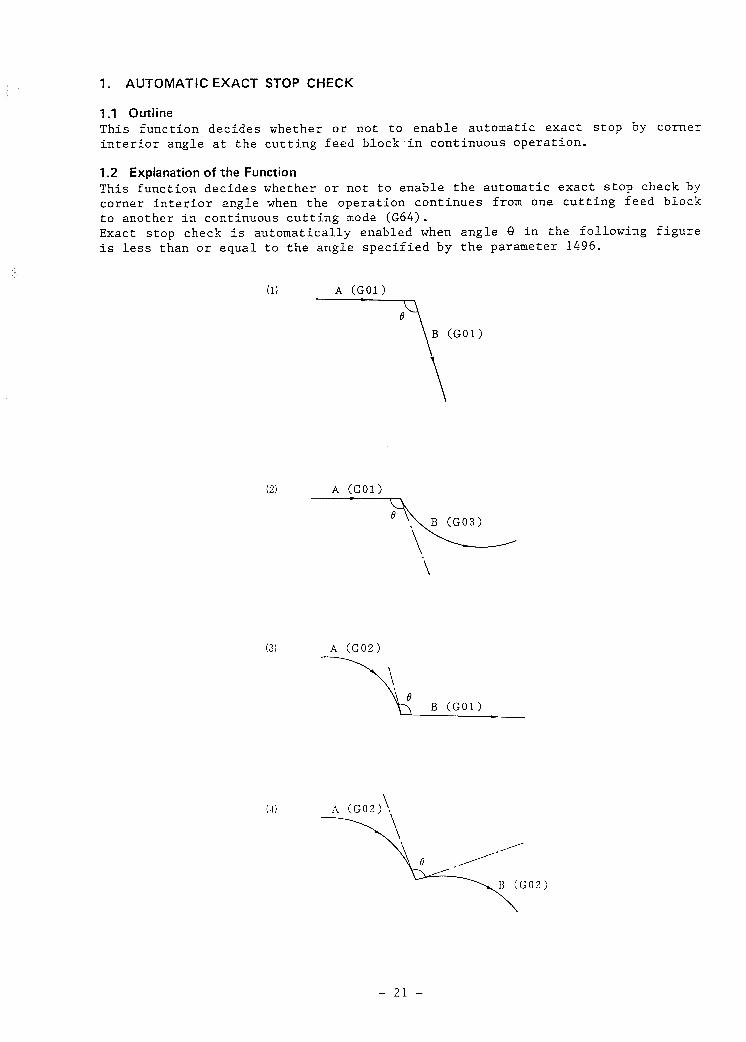
1 .l Outline
This function decides whether or not to enable automatic exact stop by corner interior angle at the cutting feed block-in continuous operation.
1.2 Explanation of the function
This function decides whether or not to enable the automatic exact stop check by corner interior angle when the operation continues from one cutting feed block
to another in continuous cutting mode (G64). Exact stop check is automatically enabled when angle 8 in the following figure is less than or equal to the angle specified by the parameter 1496.
(1) A (GM)
(GO1 >
(2) A (GOl)
(3) A (GO21
-3 B(GOl)=
- 21 -

When cutter compensation C is applied, automatic exact stop is enabled at the angle created by the programmed path. The position where exact stop is enabled
is shown below.
0 Actual path
I Program command path
A(S)
/
A B (3 /
A (S) /
I /
/ ---.p
When there is an automatic exact stop check function, exact stop is enabled at points A and B shown in the figures above. However, if this function does not exist, exact stop is executed at point S when exact stop is performed by GO9 command etc. When the linear interpolation (GOl) block and the movement amount of each axis together are a smaller minute block than the setting value of parameter No. 1497, the automatic exact stop check in that block can be made invalid.
- 22 -

’ , ‘F.\ When linear interpolation (GOl) is to be executed between A + B + C + D, auto-
matic exact stop check is executed being based on the angle 8, created by lines
AB and BC at point B, and on the angle 8, created by lines BC and CD at point C.
When the X and Y axis movement amount of block BC is smaller than the setting value of parameter No. 1497, automatic exact stop check is executed being based on the angle 8, created by line AB and CD in point C.
Note, however, that when cutter compensation C is applied, automatic exact stop
check is executed being based on the angle created by the programmed path and therefore parameter No. 1497 is made invalid.
1.3 Parameter
Data No. Data
Critical angle of automatic exact stop check
Data format : word type Data range . . 1 - 179 Data unit . . 1 deg
Data No. Data )
Minute block movement amount b
Data format : 2 word type Data range . . 0 - 99999999 Data unit . .
Set unit IS-A IS-B Unit
Metric machines 0.01 0.001 mm
Inch machines 0.001 0.0001 inch
- 23 -

: 1.4 Notes
Note 1) The automatic exact stop check function is void in gradual curve cutting
mode (G12) and follows commands GO9 and G61 whether stop check is executed or not.
- 24 -

2. GRADUAL CURVE CUTTING
2.1 Outline
When a V-axis parallel to the Y-axis is added, the gradual curve cutting cancel
mode (G13) assumes that a command for the Y-axis is also effective for the
V-axis. In gradual curve cutting mode (G12), a command for the Y-axis is effective only
for the Y-axis, and likewise, a command for the V-axis is effective only for the
V-axis.
G12;
GOlX xl Y y1 V v1 F ;
Note) G12 and G13 must be commanded by independent blocks.
2.2 Explanation of the function When a V-axis parallel to the Y-axis is added, the gradual curve cutting cancel
mode (G13) assumes that a command for the Y-axis is also effective for the
V-axis. In gradual curve cutting mode (G12), a command for the Y-axis is effective only
for the Y-axis, and likewise, a command for the V-axis is effective only for the
V-axis.
G13; Gradual curve cutting mode cancel G12; Gradual curve cutting mode
(Example of Program)
G13; G91 Y1000.0; Y500.0;
G12; Y35.OV50.0; Y4O.OV120.0;
Y axis movement amount V axis movement amount
> 1000 1000 > 500 500
> 35 50 > 40 120
Note 1) G12 and G13 must be commanded without other addresses except for
0 and N. Note 2) When V axis command is issued in G13 mode, an alarm is given. Note 3) Arc interpolation (G02, GO3) commands are not executed in G12 mode.
Note 4) G12 mode must be in G40 mode (cutter compensation cancel).
- 25 -

2.3 Parameter Gradual curve cutting has the following parameters.
Data No. Data
cl 1020
c
Program axis name of each axis .
Parameter input
Data format . . byte axis type
The program axis names of each axis control is set as given in the table below.
Axis name Set value Axis name Set value Axis name Set value
X 88 A 65 U 85 Y 89 % 66 V 86 z 90. C 67 W 87
The same program axis name is set in the axis executing parallel axis control.
Data No. Data ?
Axis number of parallel axis
Parameter input
Data-format : byte axis type
The number of each parallel axis is set in order to distinguish axes being operated in parallel. The numbers are in order starting at number 1. It is set
to 0 when there is no parallel axis. _
Data No. Data l
Setting which axis becomes the basic coordinate system of each axis 4
Parameter input
Data format : byte axis type
In order to decide the surface of arc interpolation and cutter compensation etc., each axis control sets the basic 3 axes of X, Y and 2 of the basic
coordinate system or that parallel axis. The 3 basic axes can be only set one
of the axes, but (parallel axes excluded) parallel axes can be set two or more.
(Note) The basic axes must be previous to the parallel axes.
Setting value Meaning
0 Rotating axis (neither the 3 basic axes, nor parallel axes) 1 X axis of the basic 3 axes 2 Y axis of the basic 3 axes 3 Z axis of the basic 3 axes 5 Parallel axes of X axis 6 Parallel axes of Y axis 7 Parallel axes of Z axis
- 26 -

I 3. TORCti SWIVEL CONTROL FUNCTION
3.1 Outline When open head cutting by using torch head with bevel torch (referred to as
torc'h head from hereon), it is generally necessary always to position the torch
head in a normal direction regarding the straight line or arc that has been
commanded. This function does this very well and positions the torch head in a normal
direction regarding the straight line or arc that has been commanded and
automatically controls the torch head control axis. As for straight lines, it feeds the torch head control axis at a constant speed in a normal linear direction, while performing and paralleling linear
interpolation. With regard to arcs, it positions the torch head control axis
(referred to as "C axis" below) in a normal arc direction that changes now and
then and moment by moment, while performing and paralleling arc interpolation.
3.2 Explanation of the Function
3.2.1 Definition of normal line
The torch head is positioned in a normal direction regarding the straight line and arc that has been commanded, and the C axis which is the torch head control
axis is automatically controlled. The definition of normal direction as used in
this manual is as follows. All are regarded as standard coordinate systems (right-hand Cartesian direct
coordinate system).
Pl
. Torch head
Fig. 32.1
The following explanation takes Fig. 3.2.1 as an example. With regard to straight lines, as shown in Fig. 3.2.1, the C axis is positioned
and fed at a constant speed to the angle (Ql) created between the +X axis and
the vector (Pl, P2) from the start to the end of the straight line.
Consequently, at this time, as shown in Fig. 3.2.1, the torch head is positioned
vertically to the straight line. With regard to arcs, the C axis is positioned in the angle (82 -+ 03 -+ 04) created between the +X axis and the arc tangential lines (L2 + L3 + L4).
- 27 -

Consequently, at any point on the arc, for example P3, the torch head is positioned vertically to that tangential line. . The above mentioned "the torch head is positioned in a normal direction regarding the straight line and arc that has been commanded, and the C axis is automatically controlled" means "the C axis is positioned in the angle created between the +X axis and the straight line commanded and in the angle created between the +X axis by the arc tangential lines. At this time, the torch head is premised on the fact that it is positioned at the intersection of the
straight line and the arc tangential line.
32.2 Reference point return
As explained up to now; the C axis is controlled in such a way that it is
positioned in the angle created between +X axis the commanded straight line and the angle created between +X axis and the arc tangential line. The resulting torch head is positioned at the intersection of the straight line and the arc
tangential line. However, it is necessary to determine a correspondence beforehand between the torch head positioning and the C axis positioning by a number of methods. Torch head positioning in X axis and Y axis is executed by the programming of coordinate system G92 (this is not absolutely necessary for
only incremental commands, but is necessary for only absolute commands), but this is executed by manual reference point return with regard to C axis. When manual reference point return has finished, automatic programming of coordinate system is executed. In other words, it is possible to pre-set the C
axis coordinate value to the set value with the parameter. Manual reference point return of C axis must be executed after switching power on, after cancellation of emergency stop and after cancellation of the servo alarm and C
axis automatic programming of coordinate system carried out. L
Example) Torch head position after manual Corresponds to C axis of parameter reference C axis.
point reference of (data No. 1240 - 1243) (position of
reference point seen from machine zero point.)
L
0
0
0 or 180 deg
2) IO00 ] 90 or 270 deg
Note) The set value that corresponds to C axis amongst the parameters related to
the parameter (data No. 1221 - 1225) coordinate system shift amount must be 0.
It is not possible to command C axis by program and therefore it is not possible to command reference point return check (G27), automatic reference point return
(G28, G29) and 2nd, 3rd and 4th reference point return (G30) in C axis.
32.3 Torch swivel control speed
The feed rate of C axis in automatic operation is the speed set by the parameter (data No. 1495). The speed set by the parameter is the maximum speed for C axis swivel speed in arcs. If the radius of the arc gets bigger, the change of the direction of the arc's tangential line becomes slack and therefore it goes without saying that it is slower than the parameter setting speed.
- 28 -

3.24 Torch swivel during gradual curve cutting
The torch head on each of Y, V axis in gradual curve cutting mode (G12) turns in the normal line direction of the Y, V axis movement direction independently.
+Y or +V
axis movement
V axis movement
Tdrch head on V axis
Commands gradual curve cutting start (G12) at this position
Fig. 32.4 Torch swivel during gradual curve cutting
In order to use this function, it is necessary to set the parameter to teach the
NC what axis the torch head is on. Amongst the parameters (data No. 1024) the Y
axis or V axis data that the torch head is on must be set at the appropriate places for the respective torch axes. In the same way, when Y and V axes have a parallel axis, set the torch axis
parameter that is on that parallel axis.
3.2.5 Mirror image and torch swivel
When mirror image is applied to the Y axis and V axis, the torch head is
automatically controlled so that it turns in the normal direction of the Y axis or V axis forward direction without having to especially command the mirror
image with the input signal or setting data. This control is executed independently to the torch head on the Y axis, V axis
and the respective parallel axis.
- 29 -

Y
0 Torch head C3 I
Yl axis path
Y2 axis program path
Path after Y2 axis minor image is applied
Path after VI axis mirror image is applied
Vl axis progam path
V2 axis path
fig. 32.5
Fig. 3.2.5 shows an example of gradual cutting in a machine that has torch heads
Cl, C2, C3 and C4 on axes Y1, Y2, Vl and V2. Mirror image is turned on by the input signal or setting data in Y2 axis and V2
axis. Even in circumstances such as these, it is not necessary to turn mirror
image on by the input signal or setting data in C2 axis or C3 axis. The Y and V axes and torch axis correspondence follows the previously stated
parameter (data No. 1024).
3.2.6 Parallel axis parking and torch swivel
When parallel axis exists in Y axis or V axis, the torch axis on that axis
executes torch swivel indexes even if the parking signal of any of the parallel axes is ON. Therefore, if the torch swivel index is to be closed as well, it is necessary to set the parking signal of that torch axis ON. For example, in the case where there is Yl axis and Y2 axis and a torch swivel
control axis Cl, C2 exists, when the Y1 axis and Y2 parking signals are closed,
the Y2 axis is parked and the axis movement is not executed, but C2 asis torch swivels just like the Cl axis as long as the C2 axis parking signal does not close (ON).
- 30 -

3.2.7 Torch swivel selection (input) TSE
When the torch swivel selection signal TSE contact is closed, torch swivel index
is executed and the torch head positions in the normal line direction to the
straight line and arc that has been commanded and controls the torch head control axis. Note, however, that when there are more than 2 torch head control axes and they are parallel axis controlled, the parking signals of the
respective axes are valid and the axis movements of the torch head control axis are not executed for axes whose parking signal contacts are closed. When the contact point of the signal TSE is closed, the torch swivel index is not executed. When there are more than 2 torch head control axes and they are parallel axis controlled, there is no relation to the condition of the parking
signals of the respective axes and none of the axis movements of the torch head control axes are executed. The condition of the torch swivel selection signal TSE and the parking signal
are not switched in automatic operation (when the automatic operation signal OP
is emitted).
3.2.8 Torch swivel in minute blocks
When the linear interpolation (GOl) block and the movement amount of X axis and Y axis are a smaller minute block than the setting value of the parameter (data No. 1946), the torch swivel in that block can be made invalid.
D
Torch head
When executing B -t C block, the torch head usually turns to the broken lines shown in the figure. However, when the movement amounts of both the X axis and the Y axis of B + C block are smaller than the set value of the above mentioned setting data, the torch head is the same as that of execution A + B block. That
is to say, execution from B + C block is as shown the solid line in the
figure above. In gradual curve mode (G12), torch swivel validity checks are executed independently on this minute block with regard to the torch head on the Y axis and X axis. This function is available in the following case. 1) When torch swivel is not to be executed in the minute block created for tool
offset.
When the minute block is to be operated continuously, the torch swivel will
not be executed in-between and therefore set the above mentioned setting data to 0.
- 31 -

3.3 Parameter
Data No.
(Bit)
Data
TRCH b
#7 f6 : #5 #4 a3 772 #l i0 :
Parameter input
Data format . . bit axis type
TRCH Specifies whether each axis is a torch swivel control axis or not.
0: No torch swivel control axis 1: Torch swivel control axis
Data No. Data
cl 1024 Axis number in which torch control axis exists
4 b
Parameter input
Data format : byte axis type
Data range : 1 - number of control axes
Sets the axis in which to the torch control axis exists. Sets either the Y axis or (V axis) on the torch axis.
Data No. Data l 1
Torch swivel speed /
Parameter input
Data format : word type Data unit . .
Set unit
I Remarks
IS-A IS-B
10.0 1.0 deg/min b I I 4
Data range . . 1 - 32767
- 32 -

Data No. Data .
Minute block movement amount
Parameter input
Data format : 2 word type Data unit . .
Set unit ~
IS-A IS-B Remarks
Metric machines 0.01 0.001 mm
Inch machines 0.001 0.0001 inch
Data range 0 - 99999999
3.4 Signal
3.4.1 Input signal
BMI-DI 7 6 5 4 3 2 1 0
+ .
GO29 TSE
TSE: When the torch swivel selection signal is HIGH, torch swivel index is
executed and the torch head is positioned in a normal direction to the
straight line or arc that has been commanded and controls the torch head control axis. Note, however, that when there are more than 2 torch head
control axes and they are parallel axis controlled, the parking signals of the respective axes are valid and the axis movements of the torch head
control axis whose parking signal is HIGH are not executed. When the TSE signal is LOW, the torch swivel index is not executed.
When there are more than 2 torch head control axes and they are parallel axis controlled, there is no relation to the condition of the parking signals of the respective axes and none of the axis movements of the torch
head control aces are executed. The condition of TSE and the parking signal are not switched in automatic operation.
- 33 -

4. ERROR DETECT FUNCTION
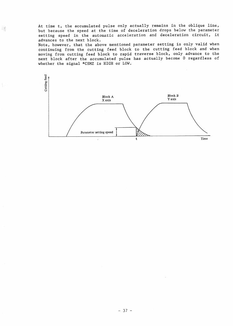
4.1 Explanation of the Function In block A when continuing from cutting feed block (block A) to cutting feed block (block B), when the speed at the time of deceleration in the automatic
acceleration and deceleration circuit of each axis drops below the set speed at parameter No. 1471, this function advances the cutting to the next block B assuming that the accumulated pulse of the automatic acceleration and
deceleration circuit of that axis has become 0. When continuing from block A to block B, this function is valid when any one of the following 4 points are relevant. 1) When GO9 (exact stop check) is commanded in block A. 2) When block A is in G61 mode (exact stop check mode). 3) In automatic exact stop check, when the angle created between block A and
block B drops below the automatic exact stop check critical angle (parameter
No. 1496).
4) When the in-position check signal *CSMZ is LOW and the parameter csz
(parameter No. 1000) is 1.
Block A X axis Y axis
Parameter setting speed
t Time
At time t, the accumulated pulse only actually remains in the oblique line, but because the speed of the automatic acceleration and deceleration circuit
drops below the parameter setting speed, it advances to the next block.
Note 1) When moving from cutting feed block to auxiliary function independent . block or rapid traverse block, advance to the next block only after the
accumulated pulse has become 0. Note 2) When the EDTC parameter, which validates this function, is set to 1, set
parameter CTP (parameter No. 1000) to 0. Note 3) When parameter No. 1471 is set to anything other than 0, when the speed
at the time of declaration in the automatic acceleration and
deceleration circuit of each axis falls below the set speed at parameter No. 1471, it advances to the next block assuming the .accumulated pulse of the automatic acceleration and deceleration circuit of each axis to be 0 and rounds corners in a curve as shown next.
- 34 -

Y
L X
Consequently, when a particularly sharp corner is executed, insert a
dwell (G04) block etc., between the two cutting feed blocks.
Example) GO9 GO1 X Y ; GO4 X0; - -
GO9 GO1 X Y ; - -
Note 4) When the in-position check signal is used as an error detect signal, set
parameter CSZ and EDTC (parameter No. 1000, 1401) to 1. Note 5) When performing acceleration and deceleration prior to interpolation, .
this function is made invalid. Note 6) This function is made invalid when feed per revolution is commanded at
either block A or block B.
4.2 Parameter 1) Parameter bit
Data No.
cl 1401
(Bit)
Data
EDTC
/7 c #6 #s #4 #3 #2 li 1 /O F
Input format : parameter input
Data format : bit type
Function . . Error detect function: 0: invalid 1: valid
2) Feed rate regarded as accumulated pulse 0
Data No. Data
Feed rate regarded as accumulated pulse 0
Input format : parameter input
Data format : word axis type
Data unit . . Set unit IS-A IS-B Unit
Metric machines 10.0 1.0 rnm/min Inch machines 1.0 0.1 inch/min Rotary axis 10.0 1.0 deg/min
Data range : 0 - 32767
- 35 -


’
INDEX
2nd feed rate override .............................................................. 4
2nd Miscellaneous Function ......................................................... 6
Znd, 3rd and 4th Reference Point Return (G30) .................................. 5
3-dimensional Tool Compensation (G40, G41) ..................................... 7
<A> Absolute/Incremental Programming (G90, G91) ....................................
ACCELERATING/DECELERATING SIGNAL .................................................
Accelerating/Decelerating Signal (Option) .......................................
Actual Spindle Speed Output .......................................................
Alarm Signal ..........................................................................
All axes interlock ..................................................................
All Axes Machine Lock ...............................................................
Automatic Acceleration/Deceleration ..............................................
Automatic Corner Override (G62) ...................................................
AUTOMATIC EXACT STOP CHECK .........................................................
Automatic Exact Stop Check (Option) ..............................................
Automatic operation all axes interlock ..........................................
Automatic Operation Lamp ...........................................................
Automatic Operation Signal .........................................................
'AUTOMATIC OPERATION .................................................................
Automatic Reference Point Return (G28, G29) ....................................
Automatic/manual simultaneous operation .........................................
Auxiliary Function Lock ............................................................
AXIS CONTROL ..........................................................................
Axis Moving Direction Signal ......................................................
Axis Moving Signal ..................................................................
Axis Name .............................................................................
Axis name .............................................................................
Axis Switching Function ............................................................
5
'43
17
6
13
12
10
4
5
21
16
12
13
13
9
5
10
10
8
13
13
3
42
8
<B>
3ackground Editing ..................................................................
Background Graphic Display .........................................................
Background*Display (Option) .......................................................
Backlash Compensation ...............................................................
Basic Address and Command Value Range ...........................................
Basic Interface (BMI) (FS6 can not be used.) ...................................
Block restart ........................................................................
3lock start interlock ...............................................................
Buffer register ......................................................................
11
11
17
8
6
14
10
12
9
i-l

~ 5
. *,
I _<
,
XC>
Cabinet . . . . . . . . . . . . . . . . . . . . . . . . . . . . . . . . . . . . . . . . . . . . . . . . . . . . . . . . . . . . . . . . . . . . . . . . . . . . . . . . 15
CABLES 6 CONNECTORS . . . . . . . . . . . . . . . . . . . . . . . . . . . . . . . . . . . . . . . . . . . . . . . . . . . . . . . . . . . . . . . . . 15
Change of Tool Offset Amount (Programmable Data Input) (GlO) . . . . . . . . . . . . . . . . 8
Change of Work Coordinate System (G92) . . . . . . . . . . . . . . . . . . . . . . . . . . . . . . . . . . . . . . . . . . 5
Circular Interpolation (602, G03) . . . . . . . . . . . . . . . . . . . . . . . . . . . . . . . . . . . . . . . . . . . . . . . . 3
COMPENSATION FUNCTION . . . . . . . . . . . . . . . . . . . . . . . . . . . . . . . . . . . . . . . . . . . . . . . . . . . . . . . . . . . . . . . 7
Connection . . . . . . . . . . . . . . . . . . . . . . . . . . . . . . . . . . . . . . . . . . . . . . . . . . . . . . . . . . . . . . . . . . . . . . . . . . . . 36
Constant Surface Speed Control Signal . . . . . . . . . . . . . . . . . . . . . . . . . . . . . . . . . . . . . . . . . . . 13
Constant Surface Speed Output (696, G97) . . . . . . . . . . . . . . . . . . . . . . . . . . . . . . . . . . . . . . . . 6
CONSTITUTION OF PROGRAM . . . . . . . . . . . . . . . . . . . . . . . . . . . . . . . . . . . . . . . . . . . . . . . . . . . . . . . . . . . . 6
Continuous Thread Cutting . . . . . . . . . . . . . . . . . . . . . . . . . . . . . . . . . . . . . . . . . . . . . . . . . . . . . . . . . . 4
Control Axis Detach . . . . . . . . . . . . . . . . . . . . . . . . . . . . . . . . . . . . . . . . . . . . . . . . . . . . . . . . . . . . . . . . . 9
Control In/Out . . . . . . . . . . . . . . . . . . . . . . . . . . . . . . . . . . . . . . . . . . . . . . . . . . . . . . . . . . . . . . . . . . . . . . . 7
Controllable Axes Expansion . . . . . . . . . . . . . . . . . . . . . . . . . . . . . . . . . . . . . . . . . . . . . . . . . . . . . . . 3
CONTROLLER . . . . . . . . . . . . . . . . . . . . . . . . . . . . . . . . . . . . . . . . . . . . . . . . . . . . . . . . . . . . . . . . . . . . . . . . . . . . 15
COORDINATE SYSTEM .................................................................... 5
Coordinate System Rotation (668, G69) ........................................... 8
COORDINATE VALUE AND DIMENSIONS ................................................... 5
CRT/MD1 AND DISPLAY ................................................................. 11
CRT/MDI Panel ........................................................................ 11
CUSTOM MACRO . . . . . . . . . . . . . . . . . . . . . . . . . . . . . . . . . . . . . . . . . . . . . . . . . . . . . . . . . . . . . . . . . . . . . . . . . . 8
Custom Macro .......................................................................... 8
Cutter Compensation ................................................................. 7
Cutter compensation B (G40 - G42) ................................................ 7
Cutter compensation C (G40 - G42) ................................................ 7
Cutting block start interlock ..................................................... 12
Cutting Feed .......................................................................... 4
Cutting feedrate clamp .............................................................. 4
Cutting Mode (G64) .................................................................. 5
Cycle start ........................................................................... 9
DATA INPUT/OUTPUT . . . . . . . . . . . . . . . . . . . . . . . . . . . . . . . . . . . . . . . . . . . . . . . . . . . . . . . . . . . . . . . . . . . . 11
Data Protection Key . . . . . . . . . . . . . . . . . . . . . . . . . . . . . . . . . . . . . . . . . . . . . . . . . . . . . . . . . . . . . . . . . 11
Decimal Point Input/Pocket Calculator Type Decimal Point Input . . . . . . . . . . . . . 5
Definition of normal line . . . . . . . . . . . . . . . . . . . . . . . . . . . . . . . . . . . . . . . . . . . . . . . . . . . . . . . . . . 27
DI Status Output Signal ............................................................ 13
DI/DO signals for individual axes ................................................ 41
Display ................................................................................ 11
Distribution End Signal ............................................................ 13
Door interlock ....................................................................... 12
Dry Run ................................................................................ 11
Dwell (GO41 ........................................................................... 5
DWELL SIGNAL . . . . . . . . . . . . . . . . . . . . . . . . . . . . . . . . . . . . . . . . . . . . . . . . . . . . . . . . . . . . . . . . . . . . . . . . . . 45
i-2

a> Emergency Stop ....................................................................... 12
Environmental Conditions ........................................................... 15
Equal Lead Thread Cutting (G33) ................................................... 4
ERROR DETECT FUNCTION ............................................................... 34
Exact Stop (G09) ..................................................................... 4
Exact Stop Mode (G61) ............................................................... 5
Executed Program Selection ......................................................... 9
Explanation of the Function ....................................................... 21
Explanation of the Function ....................................................... 25
Explanation of the Function ....................................................... 27
Explanation of the Function ....................................................... 34
Explanation of the Function ....................................................... 38
Explanation of the Function ....................................................... 43
Extended Part Program Editing ..................................................... 11
External Alarm Message .............................................................. 14
External Custom Macro Variable Input ............................................. 14
External Custom Macro Variable Output ........................................... 14
EXTERNAL DATA INPUT/OUTPUT ......................................................... 14
External Deceleration ............................................................... 12
External I/O Device Control ....................................................... 11
External Machine Coordinate System Offset ....................................... 14
External Machine Coordinate System Offset Amount Output ...................... 14
External Operator Message .......................................................... 14
External power on/off ............................................................... 15
External Program Number Output .................................................... 14
External Program Number Search .................................................... 14
External Sequence Number Output ................................................... 14
External Sequence Number Search ................................................... 14
External signals ..................................................................... 40
External Tool Offset ................................................................ 14
* External Tool Offset Amount Input ................................................ 14
External Work Coordinate System Shift ........................................... 14
External Work Coordinate System Shift Amount Output .......................... 14
EXTERNAL WORK NLJMBER SEARCH ....................................................... 14
<P>
Fl-digit feed ........................................................................ 4
FANUC CASSETTE ....................................................................... 12
FANUC PPR ............................................................................. 12
Feed fold ............................................................................. 10
FEED FUNCTION ........................................................................ 4
Feed Hold Signal ..................................................................... 13
Feed per minute (G94) ............................................................... 4
Feed per revolution (G95) .......................................................... 4
Feed rate ............................................................................. 41
Feed rate override .................................................................. 4
i-3

ol r-l . l
. . . . . . . . . . . . . . . . . . . . . . . . . . . . . . . . . . . . . . . . . . . . . . . . . . . . . . . . . . . . . . . .
35
E
3 cn
iz 0 53 E
i3 kl
c’) . . . . . . . . . . . . . . . . . . . . . . . . . . . . . . . . . . . . . . . . . . . . . . . . . . . . . . . . . . . . . . . . . . . . . . . . . . . . . . . .
i
2 . . . . . . . . . . . . . . . . . . . . . . . . . . . . . . . . . . . . . . . .
\o 4 . . . . . . . . . . . . . . . . . . . . . . . . . . . . . . . . . . . . . . .
0 r-i . . . . . . . . . . . . . . . . . . . . . . . . . . . . . . . . . . . . . . . . . . . . . . . . . . . . . . . . . . . . . . . . . .
G
0 l d
I-,
m . . . . . . . . . . . l
. . . . . . . . . . . . . . . . . . . . . . c
. . . . . . . . . . . . . . .
n 2 t3
m . . . . . . . . . . . . . . . . . . . . . . . . . . . . . . . . . . . . . . . . . . .
n E
w
w
r( . . . . . . . . . . . . . . . . . . . . . . . . . . . . . . . . . . . . . . . . . . . . . . . . . . . . . . . . . . . . . . . . . . . . . . . . . . . .
i!i l PI ? Q
, m
w
m . . . . . . . . . . . . . . . . . . . . . . . . . . . . . . . . . . . . . . . . . . . . . . . . . . . .
2 3 -# v-4
2 bfl l d cn
m
t-4 . . . . . . . . . . . . . . . . . . . . . . . . . . . . . . .
* . . . . . . . . . . . . . . . . . . . . . . . . . . . . . . .
. . . . . . . . . . . . . . . . . . . . . . . . . . . . . . . . . . . . . . . . . . . . . . . .
n 4 -J c3
co . . . . . . . . . . . . . . . . . . . . . . . . . . . . . . . . . . . . . . . . . . . . . . . . . . . . . . . . . . .
G
0
cr) . . . . . . . . . . . . . . . . . . . . . . . . . . . . . . . . . . . . . . . . . . . . . . . . . . . . . . . . . . . . . . . . . . . . .
8 c, m
0 rl . . . . . . . . . . . . . . . . . . . . . . . . . . . . . . . . . . . . . . . . . . . . . . . . . . . . . . . . . . . . . . . . . . . . .
z 2
m
4 . . . . . . . . . . . . . . . . . . . . . . . . . . . . . . . . . . . . . . . . . . . . . . . . . . . . . . . . . . . . . . . . . . . .
d z *r-i S
t . . . . . . . . . . . . . . . . . . . . . . . . . . . . . . . . . . . . . . . . . . . . . . . . . . . . . . . . . . . . . . . . . . . . . . . . . . : . . . . . . . . . . . . . . . . . . . . . . . . . . . . . . . . . . . . . . . . . . . . . . . . . . . . . . . . . . . . . . . . . . . . . . . .
co f-4 a F
t . _ m
4 . . . . . . . . . . . . . . . . . . . . . . . . . . . . . . . . . . . . . . . . . . . . . . . . . . . . . . . . . . . . . . . . . . . . . . . . . . . .
c,
cv f-l . . . . . . . . . . . . . . . . . . . . . . . . . . . . . . . . . . . . . . . . . . . . . . . . . . . . . . . . . . . . . . . . . . . . . . . . . . . . .
24
:: d $_( Q
,
-J f-4 . . . . . . . . . . . . . . . . . * . . . . . . . . . . . . . . . . . . . . . . . . . . . . . . . . . . . . . . . . . . . .
w
*cl x a
AZ
0 rd Q
,
G
0 24
:: f-l )4 Q
) G
F:
cc) . . . . . . . . . . . . . . . . . . . . . . . . . . . . . . . . . . . . . . . . . . . . . . . . . . . . . . . . . . . . . .
z z c 5 crc
z E:
w
3 &
ac; 3 ?i
$! . . . . . . . . . . . . . . . . . . . . . . . . . . . . . . . . . . . . . . . . . . . . . . . . . . . . . . . . . . . . . . . . . . . . . . . . . . . . cn
me
. .
. .
. .
. .
. .
. .
. .
. .
. .
. .
. .
. .
. .
. .
. .
. .
. .
. l
. .
. .
. .
. .
. .
. .
. .
. .
. .
. .
. : T
J
: 8
: b4
: bo
’ .2 . .
u . ; 2 . . : G
: G
.
a
; c
. 0
7 . . . . . . . . . . . . . . . . . . . . . . . . . . . . . . . . . . . . . . . . . 9 . . . . . . . . . . . . . . . . . . . . . . . .
“do l d
c, l d
z T4
. . . . . . . . . . . . . . . . . . . . . . . . . . . . . . . . . . . . . . . . . . . . . . . . . . . . . . . . . . . . . . r-i
d 2 ‘;: 8f 0 G
0 8
.
. . .
. .
. .
. .
. .
. .
. .
. .
. .
. .
. .
. .
. .
. .
. .
. .
. .
. .
. .
. .
. .
. .
. .
. *
. .
. .
. .
. .
c .
. .
. 0
.
. u
. .
a .
. h
. .
. .
5 .
. .
. G
.
. w
.
. E
.
. .
. z
. . Q
! bn
.

4!!P
Machine Coordinate System (G53) ...................................................
MACHINE INTERFACE ....................................................................
Machine Lock on Each Axis ..........................................................
Main Program ..........................................................................
Manual Absolute On/Off ..............................................................
Manual Arbitrary Angle Feed .......................................................
Manual Continuous Feed ..............................................................
Manual Data Input (MDI) ............................................................
Manual Handle Feed (1st) ...........................................................
Manual Handle Feed (2nd, 3rd) .....................................................
Manual Interruption during Automatic Operation ................................
Manual Numerical command ...........................................................
MAWAL OPERATION .....................................................................
Manual operation .....................................................................
Manual Reference Point Return .....................................................
Maximum Stroke .......................................................................
MD1 operation ........................................................................
MEASUREMENT FUNCTION ................................................................
Mechanical Handle Feed ..............................................................
Memory operation .....................................................................
Menu Switch f
...........................................................................
Mirror image and torch swivel .....................................................
Mirror Image ..........................................................................
MISCELLANEOUS FUNCTION ..............................................................
Miscellaneous Function ..............................................................
Multi-step Skip Function (G31.1, G31.2, G31.3) ................................
Multi-tap transformer ...............................................................
<N>
NC Ready Signal ......................................................................
NC Window .............................................................................
Notes ..................................................................................
Number of Basic Controlled axis ...................................................
Number of Basic Simultaneous Controllable Axes ................................
Number of Common Variable ..........................................................
NUM3ER OF CONTROLLED AXIS ..........................................................
Number of Tool Offsets ..............................................................
<O>
Operation Mode .......................................................................
Optional Angle Chamfering ..........................................................
Optional Angle Corner R ............................................................
Optional Block Skip .................................................................
Optional Block Skip Addition ......................................................
Outline ................................................................................
Outline ................................................................................
i-5
5
14
10
6
10
10
10
11
10
10
10
10
10
41
5
3
9
8
8
9
11
29,
9
6
6
8
15
13
15 -
24
3
3
8
3
8
9
7
7
7
7
21
25

Outline ................................................................................ 27
Outline ................................................................................ 43
Override .............................................................................. 4
Override cancel ...................................................................... 4
Overtravel ............................................................................ 12
PARALLEL AXIS CONTROL FUNCTION .................................................... 38
Parallel Axis Control ............................................................... 9
Parallel axis parking and torch swivel .......................................... 30
Parameter ............................................................................. 23
Parameter ............................................................................. 26
Parameter ............................................................................. 32
Parameter ............................................................................. 35
Parameters ............................................................................ 43
Parameters Involved in Parallel Operation ....................................... 42
Parking signal ....................................................................... 41
PART PROGRAM STORAGE & EDITING .................................................... 11
Playback .............................................................................. 11
Polar Coordinate Command (G15, G16) .............................................. 5
Portable tape reader ................................................................ 12
Position Detection System .......................................................... 15
Position Detector .................................................................... 15
Positioning (GOO) .................................................................... 3
POWER MAGNETICS INTERFACE .......................................................... 14
Power .................................................................................. 15
Power Ready Signal .................................................................. 13
Precautions for Parallel Operation ............................................... 42
PREFACE .............................................................................. ..P- 1
PREPARATION FUNCTION ................................................................ 3
Program end (M02, M30) .............................................................. 9
Program Name .......................................................................... 6
Program Number ....................................................................... 6
Program number search ............................................................... 9
Program restart ...................................................................... 10
Program stop (MOO, MOl) ............................................................ 9
PROGUMMABLE CONTROLLER (PMC-N) ................................................... 15
Programmable Mirror Image (G50.1, G50.2) ........................................ 7
Radius Designation on Arc .......................................................... 7
Rapid Traverse ....................................................................... 4
Rapid traverse override ............................................................ 4
Rapid Traversing Signal ............................................................ 13
Reader/Puncher Interface ........................................................... 12
REFERENCE POINT . . . . . . . . . . . . . . . . . . . . . . . . . . . . . . . . . . . . . . . . . . . . . . . . . . . . . . . . . . . . . . . . . . . . . . 5
i-6

Reference Point Return Check (G27) ............................................... 5
Reference point return .............................................................. 28
Regenerative Discharge Unit ....................................................... 15
Registerable Programs ............................................................... 11
Remote Operation Function (G80, 681) ............................................. 7
Reset .................................................................................. 10
Reset Signal .......................................................................... 13
Restart of Automatic Operation .................................................... 10
Retrace ................................................................................ 10
Rewind ................................................................................. 9
Rewinding Signal ..................................................................... 13
Run Hour and Parts Count Display ................................................. 11
<S>
S Code Output ........................................................................ 6
Scaling (G50, G51) .................................................................. 8
Selection of coordinate system .................................................... 38
SELF-DIAGNOSIS FUNCTION ............................................................ 11
Sequence Number ...................................................................... 6
Sequence number comparison and stop .............................................. 9
Sequence number search .............................................................. 9
SERVO .................................................................................. 15
Servo Connection and Assembly ..................................................... 15
Servo Motor ........................................................................... 15
Servo Off ............................................................................. 9
Servo Ready Signal .................................................................. 13
Shift amount .......................................................................... 41
Signal ................................................................................. 33
Signal ................................................................................. 45
Signals ................................................................................ 44
Simultaneous Controllable Axes Expansion ........................................ 3
Single Block .......................................................................... 11
Single Direction Positioning (G60) ............................................... 3
Skip Function (G31) ................................................................. 8
Specification ........................................................................ 45
SPINDLE FUNCTION ..................................................................... 6
Spindle Speed Analog Output ....................................................... 6
Spindle Speed Binary Code Output ................................................. 6
Spindle Speed Clamp (G92) .......................................................... 6
Start of Automatic Operation ...................................................... 9
Start of Automatic Operation ...................................................... 9
STATUS OUTPUT ........................................................................ 13
Stop of Automatic Operation ....................................................... 9
Stored Pitch Error Compensation ................................................... 8
Stored stroke check 1 ............................................................... 12
Stored stroke check 2 (G22, G23) . . . . . . . . . . . . . . . . . . . . . . . . . . . . . . . . . . . . . . . . . . . . . . . . . 12
Straightness Compensation . . . . . . . . . . . . . . . . . . . . . . . . . . . . . . . . . . . . . . . . . . . . . . . . . . . . . . . . . . 8
i-7

Stroke check before movement . . . . . . . . . . . . . . . . . . . . . . . . . . . . . . . . . . . . . . . . . . . . . . . . . . . . . . 12
Subcategory lettering . . . . . . . . . . . . . . . . . . . . . . . . . . . . . . . . . . . . . . . . . . . . . . . . . . . . . . . . . . . . . . . 42
Subprogram . . . . . . . . . . . . . . . . . . . . . . . . . . . . . . . . . . . . . . . . . . . . . . . . . . . . . . . . . . . . . . . . . . . . . . . . . . . . 6
T Code Output . . . . . . . . . . . . . . . . . . . . . . . . . . . . . . . . . . . . . . . . . . . . . . . . . . . . . . . . . . . . . . . . . . . . . . . . 6
Tangential speed constant control ........................ . ....................... 4
Tape Code ............................................................................. 6
Tape Format . . . . . . . . . . . . . . . . . . . . . . . . . . . . . . . . . . . . . . . . . . . . . . . . . . . . . . . . . . . . . . . . . . . . . . . . . . . 7
Tape operation . . . . . . . . . . . . . . . . . . . . . . . . . . . . . . . . . . . . . . . . . . . . . . . . . . . . . . . . . . . . . . . . . . . . . . . 9
Tape Reader . . . . . . . . . . . . . . . . . . . . . . . . . . . . . . . . . . . . . . . . . . . . . . . . . . . . . . . . . . . . . . . . . . . . . . . . . . . 11
Tape reader with reels . . . . . . . . . . . . . . . . . . . . . . . . . . . . . . . . . . . . . . . . . . . . . . . . . . . . . . . . . . . . . . 12
Tape reader without reels .......................................................... 11
Tapping Mode (G63) .................................................................. 5
Tapping Signal . . . . . . . . . . . . . . . . . . . . . . . . . . . . . . . . . . . . . . . . . . . . . . . . . . . . . . . . . . . . . . . . . . . . . . . 13
TEST FUNCTION OF PROGE2AM . . . . . . . . . . . . . . . . . . . . . . . . . . . . . . . . . . . . . . . . . . . . . . . . . . . . . . . . . . . 10
The relationship between tool length compensation and tool position
compensation .......................................................................... 41
THREAD CUTTING ....................................................................... 4
Thread Cutting Signal ............................................................... 13
TOOL FUNCTION ........................................................................ 6
Tool length compensation and tool offset ........................................ 39
Tool length offset bias amount .................................................... 42
Tool Life Management ................................................................ 6
Tool Offset (G45 - G48) ............................................................ 7
Tool Offset Memory .................................................................. 7
Tool offset memory A ................................................................ 7
Tool offset memory B ................................................................ 7
Tool offset memory C ................................................................ 7
Tool position offset bias amount ................................................. 42
Tool radius compensation ........................................................... 42
’ TORCH SWIVEL CONTROL FUNCTION ..................................................... 27
Torch Swivel Control ................................................................ 17
Torch swivel control speed ......................................................... 28
Torch swivel during gradual curve cutting ....................................... 29
Torch swivel in minute blocks ..................................................... 31
Torch swivel selection (input) TSE ............................................... 31
Velocity Control Unit . . . . . . . . . . . . . . . . . . . . . . . . . . . . . . . . . . . . . . . . . . . . . . . . . . . . . . . . . . . . . . . 15
Weight . . . . . . . . . . . . . . . . . . . . . . . . . . . . . . . . . . . . . . . . . . . . . . . . . . . . . . . . . . . . . . . . . . . . . . . . . . . . . . . . . 15
What are parallel axes? ............................................................ 38
Work Coordinate System (G54 - G59) ............................................... 5
Work Origin Offset Value Change (Programmable Data Input) (GlO) ............ 5
i-8


· No part of this manual may bereproduced in any form.
· All specifications and designsare subject to change withoutnotice.