Embed Size (px)
Citation preview
GE 8000-LineMotor Control Centers Structure
B-1
B

Spectra Series™ and 8000-LineMotor Control Centers Structure
B-2
ENCLOSURE TYPESTYPE 1–General Purpose, Indoor
Intended for use indoors, primarily to prevent accidental contactof personnel with the enclosed equipment, in areas where unusualservice conditions do not exist. In addition, they provide protectionagainst falling dirt.
TYPE 1 GASKETED–Semi Dust-tight,Indoor
Intended to restrict the entrance of dust and dirt into Type 1enclosures, but are not dust-tight. Standard is closed-cell gasket-ing material.
TYPE 2–Drip-proof, IndoorIntended for use indoors to protect the enclosed equipment
against falling noncorrosive liquids and falling dirt. These enclo-sures have provision for drainage. Dripshields on top of the motorcontrol center and neoprene closed–cell gasketing afford protec-tion from falling and splashing liquids. They are not water-tight.
TYPE 3R–Rain-proof, OutdoorIntended for use outdoors to protect the enclosed equipment
against rain. They are not dust-proof, snow-proof nor sleet-proof(ice-proof).
TYPE 12–Industrial Use–Dust-tight andDrip-tight, Indoor
Intended for use indoors to protect the enclosed equipmentagainst fibers, flyings, lint, dust and dirt, and light splashing, seep-age, dripping, and external condensation of noncorrosive liquids.
INDOOR ENCLOSURESGE motor control centers are made up of standardized vertical
sections housing vertical and horizontal bus, wiring channels andcompartmented control units. Sections may be bolted together toform a single panel assembly powered by line connection at a sin-gle point. Normal shipping split is three sections maximum.
STANDARD NEMA 1 or NEMA 1 (GASKETED)ENCLOSURES
Standard finish is light-gray ANSI 61 over a phosphate rustinhibitor. All unpainted parts are zinc-chromate electroplated. 20- and 22-inch deep enclosures are furnished with hinged doorson the rear, while the 13-inch deep enclosures are supplied withbolt-on rear covers. Pan-type doors utilize quarter-turn fasteners.Gasketed doors, cover plates, and operating handles are availableas an option. Two heavy-duty 3-inch-by-11/2-inch,12-gauge floorsills and 3-inch full-length lifting beam are included. Open bottomis standard.
NEMA 2 DRIP-PROOF CONSTRUCTIONSimilar to NEMA 12 gasketed construction except with pan-type
dripshield on top and with open bottom. Dripshield extends fourinches beyond front of motor control center. Standard finish: lightgray ANSI 61. Furnished with removable conduit cover platesunless otherwise specified.
NEMA 12Similar to NEMA 1 gasketed construction except that bottom
plates are furnished and all removable plates are gasketed.
HOW TO DEFINE UNUSED SPACESFuture Unit Space– Unit space specified and equipped
to accept a future unit.
Blank Unit Space– Unit space not equipped to accept a future unit.
Unuseable Unit Space– Unit space not suitable to acceptaccept a future unit.

Spectra Series™ and 8000-LineMotor Control Centers Structure
B-3
INDOOR ENCLOSURES
B
Enclosure Height 90” 78”
Horizontal Bus 2” Bus 4” Bus 2” Bus 4” Bus
Top Wireway 6”➀ 12” 12” 12”➀ 12”➀ 18” 6”➀ 12” 12” 12”➀ 12”➀ 18”Bottom wireway 12”¿ 6” 12” 6” 12”¿ 6” 12”¿ 6” 12” 6” 12”¿ 6”No S.U.’s➁ 6 6 51/2 6 51/2 51/2 5 5 41/2 5 41/2 41/2
Notes:• One S.U. = 12-inch vertical height.• Average weight per vertical section including units–500 lbs.
➀ A 1/2 S.U. unit cannot be mounted immediately below a 6-inch top wireway with 2-inch bus, or immediately below a12-inch wireway with 4-inch bus.
➁ On back-to-back sections, the rear side must always have a12-inch top wireway with 2-inch bus and an 18-inch top wire-way with 4-inch bus.
Front view Side view13-inch-deep section
(1200 amp max.)
Side view20- or 22-inch-deep section
(Front mounted only)(20” - 1600 amp max.)
(22” - 2000/2500 amp only)
Side view20- or 22-inch-deep section
(Back-to-Back)(20” - 1200 amp max.)
(22” - 2000/2500 amp only)
Spectra Series™ and 8000-LineMotor Control Centers Structure
B-4
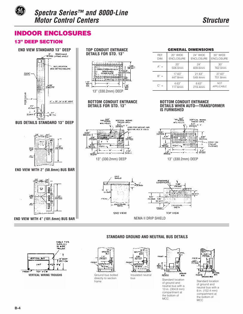
INDOOR ENCLOSURES13” DEEP SECTION
GENERAL DIMENSIONSREF. 20” WIDE 24” WIDE 30” WIDEDIM. ENCLOSURE ENCLOSURE ENCLOSURE
A” =
B” =
C” =
20”508.0mm
17.63”447.8mm
21.63”549.4mm
27.63”701.8mm
4.63”117.6mm
8.63”219.4mm
NOTAPPLICABLE
24”609.6mm
30”762.0mm
END VIEW STANDARD 13” DEEP
BUS DETAILS STANDARD 13” DEEP
END VIEW WITH 2” (50.8mm) BUS BAR
END VIEW WITH 4” (101.6mm) BUS BAR
STANDARD GROUND AND NEUTRAL BUS DETAILS
TOP CONDUIT ENTRANCEDETAILS FOR STD. 13”
BOTTOM CONDUIT ENTRANCEDETAILS FOR STD. 13”
BOTTOM CONDUIT ENTRANCEDETAILS WHEN AUTO—TRANSFORMERIS FURNISHED
13” (330.2mm) DEEP
13” (330.2mm) DEEP 13” (330.2mm) DEEP
NEMA II DRIP SHIELD
VERTICAL WIRING TROUGHS Ground bus bolteddirectly to sectionframe
Insulated neutralbus Standard location
of ground andneutral bus with a12-in. (304.8 mm)compartment atthe bottom ofMCC
Standard locationof ground andneutral bus with a6-in. (152.4 mm)compartment atthe bottom ofMCC

Spectra Series™ and 8000-LineMotor Control Centers Structure
B-5
20” DEEP SECTION
B
VERT
ICAL
WIR
ING
TROU
GHS
END
VIEW
WIT
H4”
(101
.6m
m) B
USBA
R
END
VIEW
WIT
H2”
(50.
8mm
) BUS
BAR
BOTT
OM C
ONDU
IT E
NTRA
NCE
DETA
ILS
WHE
N AU
TO-T
RANS
FORM
ER IS
FUR
NISH
ED
STAN
DARD
GRO
UND
AND
NEUT
RAL
BUS
DETA
ILS
BOTT
OM C
ONDU
IT E
NTRA
NCE
TOP
COND
UIT
ENTR
ANCE
BUS
DETA
ILS
STAN
DARD
20”
DEEP
END
VIEW
STAN
DARD
20”
DEEP
20”
(508
.0M
M) D
EEP
BACK
-TO-
BACK
(SIZ
E 3,
4)
20”
(508
.0m
m) D
EEP
NEM
AII
DRIP
SHIE
LDG
EN
ER
AL
DIM
EN
SIO
NS
RE
F.20
” W
IDE
24”
WID
E30
” W
IDE
DIM
.E
NC
LO
SU
RE
EN
CL
OS
UR
EE
NC
LO
SU
RE
A”
=
B”
=
C”
=
20”
508.
0mm
17.6
3”44
7.8m
m21
.63”
549.
4mm
27.6
3”70
1.8m
m
4.63
”11
7.6m
m8.
63”
219.
4mm
NO
TA
PP
LIC
AB
LE
24”
609.
6mm
30”
762.
0mm
Spectra Series™ and 8000-LineMotor Control Centers Structure
B-6
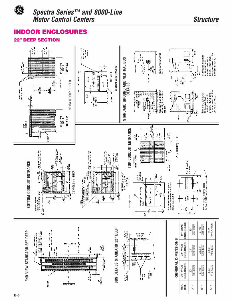
INDOOR ENCLOSURES22” DEEP SECTION
GE
NE
RA
LD
IME
NS
ION
SR
EF.
20”
WID
E24
” W
IDE
30”
WID
ED
IM.
EN
CL
OS
UR
EE
NC
LO
SU
RE
EN
CL
OS
UR
E
A”
=
B”
=
C”
=
20”
508.
0mm
17.6
3”44
7.8m
m21
.63”
549.
4mm
27.6
3”70
1.8m
m
4.63
”11
7.6m
m8.
63”
219.
4mm
NO
TA
PP
LIC
AB
LE
24”
609.
6mm
30”
762.
0mm
NEM
AII
DRIP
SHIE
LD
STAN
DARD
GROU
ND A
ND N
EUTR
AL B
USDE
TAIL
S
BOTT
OMCO
NDUI
TEN
TRAN
CE
TOP
COND
UIT
ENTR
ANCE
END
VIEW
STAN
DARD
22”
DEEP
BUS
DETA
ILS
STAN
DARD
22”
DEEP

Spectra Series™ and 8000-LineMotor Control Centers Structure
B-7
30” DEEP SECTION
B
GENERAL DIMENSIONSREF. 20” WIDE 24” WIDE 30” WIDEDIM. ENCLOSURE ENCLOSURE ENCLOSURE
A” =
B” =
C” =
20”508.0mm
17.63”447.8mm
21.63”549.4mm
27.63”701.8mm
4.63”117.6mm
8.63”219.4mm
NOTAPPLICABLE
24”609.6mm
30”762.0mm
END VIEW STANDARD 30” DEEP
BUS DETAILS STANDARD 30” DEEP
END VIEW WITH 2” (50.8mm) BUS BAR
END VIEW WITH 4” (101.6mm) BUS BAR
TOP CONDUIT ENTRANCE DETAILS BOTTOM CONDUIT ENTRANCE
STANDARD GROUND AND NEUTRAL BUS DETAILS
30” (762.0mm) DEEP
END VIEW TOP VIEW
NEMA II DRIP SHIELD
Spectra Series™ and 8000-LineMotor Control Centers Structure
B-8
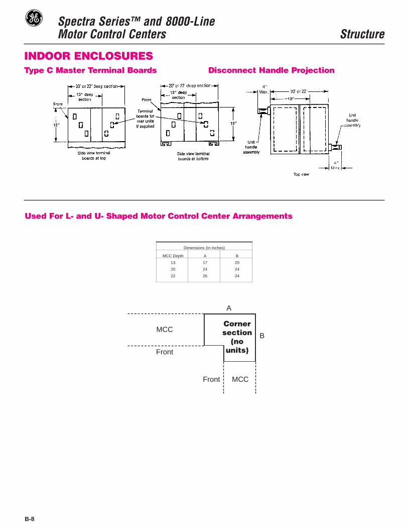
INDOOR ENCLOSURESType C Master Terminal Boards Disconnect Handle Projection
Used For L- and U- Shaped Motor Control Center Arrangements
Dimensions (In Inches)
MCC Depth A B
13 17 20
20 24 24
22 26 24
Cornersection
(nounits)
Front MCC
MCC
Front
B
A
Spectra Series™ and 8000-LineMotor Control Centers Structure
B-9
OPTIONS
Space HeatersSpace heaters are used to prevent moisture condensation on
the inside of the motor control center. One heater (62.5 watts at120 volts AC) is installed in the bottom of each vertical section.UL requires space heaters be controlled by a thermostat. Onethermostat can control up to 14 heaters and is located in the tophorizontal wireway.
A terminal board for connecting an external 120-volt powersource is standard. The terminal board is located in the top hori-zontal wireway adjacent to the thermostat(s). This is recommend-ed since it permits the space heaters to be energized and effec-tive even when the motor control center itself is deenergized. Ifexport crating is involved, the space heater circuit can be wiredto an external plug for energizing the heaters during shipmentand storage.
When specified, space heater power can be provided fromwithin the motor control center. Include the required distributiontransformer with primary and secondary protection in the motorcontrol center.
An enclosed foreign voltage disconnect switch is available asan option.
Bottom PlatesPlates bolt on to the bottom of each motor control center sec-
tion. They may be removed to facilitate installing conduit.
Starters Mounted Back-to-Back (Single Section)This construction requires a minimum 20-inch deep enclo-
sure. A common main horizontal bus is furnished with individualfront and rear vertical buses to maintain same phase sequence,front and rear. This allows for mounting draw-out units in the rearof the section without changing phasing.
The back-to-back section is UL labelled per table below andcan be mounted in a NEMA 3R non-walk-in outdoor enclosure.
Care must be exercised when arranging units as some of thelarger starters, power transformers, etc., require the full enclo-sure depth.
Back-to-Back Availability
Back-To-Back Line Ups13-inch through 22-inch motor control center equipments may
be mounted back-to-back provided back access is not required.Refer to the factory, noting specific requirements. This arrange-ment may require a main bus transition assembly.
Extended Height Pull Box (Top Hat)A pull box can be mounted on top of a vertical section when
specified. The standard height is 12 inches; 6-, 18-, and 24-inchheights are also available. Top, front, and end covers are remov-able for access.
Rodent BarriersMetal plates bolted to the bottom of each end section to close
the opening between the front and rear floor sills. Not required ifthe floor sills will be removed or imbedded in concrete.
Structural Floor Sills11/2-inch X 3-inch structural channels are furnished in place of
standard formed channels.
Extra Width Vertical Wireway24-inch wide sections can be furnished with 8-inch wide verti-
cal wireway and door.
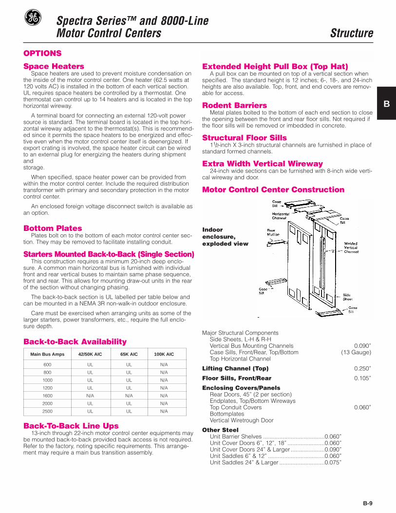
Motor Control Center Construction
Major Structural ComponentsSide Sheets, L-H & R-HVertical Bus Mounting Channels 0.090”Case Sills, Front/Rear, Top/Bottom (13 Gauge)Top Horizontal Channel
Lifting Channel (Top) 0.250”
Floor Sills, Front/Rear 0.105”
Enclosing Covers/PanelsRear Doors, 45” (2 per section)Endplates, Top/Bottom WirewaysTop Conduit Covers 0.060”BottomplatesVertical Wiretrough Door
Other SteelUnit Barrier Shelves ......................................0.060”Unit Cover Doors 6”, 12”, 18” .......................0.060”Unit Cover Doors 24” & Larger .....................0.090”Unit Saddles 6” & 12” ...................................0.060”Unit Saddles 24” & Larger ............................0.075”
B
Main Bus Amps 42/50K AIC 65K AIC 100K AIC
600 UL UL N/A
800 UL UL N/A
1000 UL UL N/A
1200 UL UL N/A
1600 N/A N/A N/A
2000 UL UL N/A
2500 UL UL N/A
Indoorenclosure,exploded view
Spectra Series™ and 8000-LineMotor Control Centers Structure
B-10
ENCLOSURES
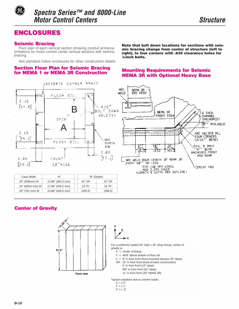
Seismic BracingFloor plan of each vertical section showing conduit entrance
limitations for motor control center vertical sections with seismicbracing.
See standard indoor enclosures for other construction details.
Section Floor Plan for Seismic Bracingfor NEMA 1 or NEMA 3R Construction
Note that bolt down locations for sections with seis-mic bracing change from center of structure (left toright), to four corners with .635 clearance holes for1/2-inch bolts.
Mounting Requirements for SeismicNEMA 3R with Optional Heavy Base
Case Width “A” “B” (Depth)
20” (508mm) W 13.88” (352.5 mm) 20” DP 22” DP
24” (609.6 mm) W 17.88” (454.2 mm) 13.75” 15.75”
30” (762 mm) W 23.88” (606.6 mm) (349.2) (398.5)
Center of Gravity
For a uniformly loaded 90” high x 20” deep lineup, center ofgravity is:
X = center of lineupY = 461/2” above bottom of floor sillZ = 8” in from front (front-mounted devices 20” deep)OR: 10” in from front (back-to-back construction)Z = 5” in from front (13” deep)Z = 81/2” in from front (22” deep)Z = 11” in from front (25” NEMA 3R)
Typical variations due to uneven loads:X = ± 5”Y = ± 1”Z = ± .5”
B
A

Spectra Series™ and 8000-LineMotor Control Centers Structure
B-11
OUTDOOR ENCLOSURESNEMA 3R NON-WALK-IN ENCLOSURE(STANDARD)
The standard NEMA 3R enclosure consists of a speciallyconstructed MCC section with a mating framework whichsupports the roof and extended front. The basic design issimilar to switchboard construction. The smaller footprint willpermit a broader usage than the optional NEMA 3R construc-tion. Meets Seismic Zone 4 (optional). ➃
B
Module Width MCC Split Length(Total) A (S1 & S2) ➁
25 2.5 20”
30 3.0 24”
35 2.5 30”
45 2.5 40”
50 3.0 44”
55 2.5 50”
55 3.5 48”
60 3.0 54”
65 2.5 60”
NOTES:➀ Doors shown are double doors, or MW
less than 45” door will be single door.➁ NEMA 3R module may contain 1, 2 or 3
MCC sections, 3 section shipping splitlimited to (3) 20” wide MCC sections only.
➂ All dimensions in inches.➃ For Seismic mounting see Sh # B-10
MCC Front TopDepth Extension Cover
(C) (B) (D)
20” 5 35
22” 8 40
30” Plus 5 4522” 13
(D)
(B) (C)
25.00
30.00
35.003022
MODULE MODULE WIDTH
20” DEEP MCC FLOOR PLAN
22” DEEP MCC FLOOR PLAN
30/22” DEEP MCC FLOOR PLAN
FOR CONDUIT OPENINGAND BOLT DOWN HOLE DIM.
SEE SH #B-5
FOR CONDUIT OPENINGAND BOLT DOWN HOLE DIM.
SEE SH #B-6
FOR CONDUIT OPENINGAND BOLT DOWN HOLE DIM.
SEE SH #B-6, 7
MODULE WIDTH MODULE
MODULE WIDTH MODULE WIDTH

Spectra Series™ and 8000-LineMotor Control Centers Structure
B-12
General Electric’s outdoor construction consists of an indoor(20-inch deep only) motor control center line-up in an outdoorenclosure. Standard NEMA 3R enclosures generally house twoor more vertical sections and are bolt-together type constructionwith provision for future expansion. Standard construction willwithstand wind velocities up to 75 mph. Roof loading should belimited to 30 lbs./ft2. Exterior finish is an air-dry alkyd enamelANSI 61 (light gray) over a phosphate corrosion-resistant primer.Outdoor enclosures are approximately 104 inches overall height.Floor plates beneath the interior motor control center line-up arenot provided. If required, order motor control center bottomplates with the motor control center sections. Space heaters withthermostatic control are recommended in the motor control cen-ter line-up. Refer to specific job drawings for mounting andanchoring details.
NEMA 3R outdoor enclosures are available in four enclosuretypes:
• NEMA 3R non-walk-in
• NEMA 3R non-walk-in (back-to-back)• NEMA 3R walk-in• NEMA 3R common-aisle, walk-through
Each NEMA 3R module may vary in width from 20 inches to48 inches, and modules of varying width may be bolted togetherto form a single shipping section. With the standard base a max-imum of two modules can be shipped bolted together. Specify aheavy base under the following conditions:
• If more than two NEMA 3R modules form a single shipping section.
• Rear access to the motor control center is specified.• Wall insulation is specified.• Extended height is specified.• Wind withstandability above 75 mph (130 mph max.)• Seismic withstandability is specified (Zone 4, 2.25g max.).• NEMA 3R walk-through construction is required.
OUTDOOR ENCLOSURESNEMA 3R WEATHERPROOF ENCLOSURE (OPTIONAL)
OUTDOOR ENCLOSURE FEATURESFeature 3R Non-Walk-In 3R Non-Walk-In 3R Walk-In 3R Walk Through
Rear Access Standard Optional – Optional OptionalLouvered Door Ventilation – Standard Standard Standard –Filters For Door Ventilation – Optional Optional Optional –Top or End Ventilation Standard – – Optional OptionalFilters for Top or End Ventilation – – – Optional OptionalInsulation–Top & Sides – Optional Optional Optional OptionalInsulation–Top Only – Optional Optional Optional OptionalFluorescent Lighting, Switches and Convenience Outlets Optional Optional – Optional Optional130 mph Wind Withstandability Optional Optional Optional Optional OptionalSeismic Withstandability (2.25G Max) Optional Optional Optional Optional OptionalExtended Height (10”) – Optional Optional Optional OptionalDoor Stops Standard Standard Standard Standard –Panic Door Hardware – – – – StandardRemovable Floor Plates in Front of MCC – Standard Standard Standard StandardKey Lockable Doors (cylinder lock) Padlock Prov. Standard Standard Standard StandardHeating and Cooling – Optional Optional Optional OptionalHeavy Base Optional Optional Optional Standard
STANDARD OPTIONAL
3R Non-Walk-InBack-To-Back

Spectra Series™ and 8000-LineMotor Control Centers Structure
B-13
OUTDOOR ENCLOSURE DIMENSIONS
Optional NEMA 3R Outdoor Non-Walk-In
B
Optional NEMA 3R Outdoor Non-Walk-In(Back-to-Back)
GENERAL NOTES:• NEMA 3R bolt-down hole size and location is subject to change
depending on equipment requirements. See specific job drawings.• Average shipping weight of all outdoor enclosures is based on 50
lbs. per square foot of floor space plus the weight of the interiormotor control center line-ups.
• Some local codes require 30-inch minimum door width.

Spectra Series™ and 8000-LineMotor Control Centers Structure
B-14
OUTDOOR ENCLOSURE DIMENSIONS
Optional NEMA 3R Outdoor Walk-In
Optional NEMA 3R Outdoor Common-AisleWalk Through

Spectra Series™ and 8000-LineMotor Control Centers Structure
B-15
BUS SELECTIONAll continuous–current rating selections or recommendations
are based on the motor control center being located in a maxi-mum 40° C (104°F) ambient. Refer to General (Section A) forother environmental considerations.
MAIN HORIZONTAL BUSThe size of motor control center main bus and cables feeding
the main bus is based on the current-carrying capacity requiredfor motors plus other connected loads.
The capacity required for motors can be taken as 125 percentof the full-load rating of the largest motor plus 100 percent of thefull-load rating of all other motors to be operated at the sametime. Modified requirements resulting from duty-cycle or demandfactor can be taken into account.
The current-carrying capacity required for other connectedloads should be computed on the basis of 100 percent of thesum of individual loads except where a demand factor can prop-erly be applied to reduce this total. Consideration should begiven to future requirements.
VERTICAL BUS EXTENSIONSThe maximum vertical bus loading is calculated as follows: 80
percent of the feeder trip or fuse clip rating, plus 100 percent ofthe starter full load amps, plus 25 percent of the largest motorfull load amps. This total cannot exceed the vertical bus rating.Tin plated copper verticval bus is standard, with silver platingas an option.
NEUTRAL BUSNeutral bus is normally rated 50 percent or 100 percent of the
main bus ampacity depending on system requirements.
GROUND BUSUL requires a ground bus in multisection motor control cen-
ters. 300 ampere Cu or 375 ampere Al ground bus will meet min-imum size requirements for main busses rated through 2000amperes. A clearance hole for 3/8-inch hardware is provided ineach section.
OPTIONSThe following UL listed options are available:
• Cap plugs for unused vertical bus stab openings.• Shutter mechanism for vertical bus stab openings.• Fully-insulated main horizontal bus.• Silver plated horizontal and vertical bus.• Plated ground bus (tin/silver).
B
BUS SYSTEMS/SELECTIONMaterial Short-Circuit Rating in RMS Symmetrical Amperes–(kA)
Cu Alum➇ 42 65➈ 100➁
600 X X X X X –2” Bus800 X X X X ¬2” Bus
Main Horizontal 1000 X X X X ➃ 2” Bus1200 X X X X X X ➀ 4” Bus
1600➄➆ X X X X X ➀ 4” Bus2000➅ X X X X X ➀ 4” Bus2500➅ X X X X X ➀ 4” Bus
300 X X X XVertical 450 X X X X
600 X X X X X ➂
300 X X375 X X600 X X X
Neutral 800 X X X1000 X X1200 X X X1250 X X
300 X X 1/4” x 1”375 X X 1/4” x 2”
Horizontal Ground 600 X X 1/4” X 2”600 X X 3/8” X 2”
Vertical Grounds 150 X X 1/8” x 1”
MCC BusContinuous Current
Rating AmperesUL Notes
➀ 4-inch bus requires top 18-inch motor control center bus compartment.➁ Not available in back-to-back construction (requires 4" main bus with 600 A vertical bus)➂ Required for all bolt-in assemblies.➃ Can be UL rated at 1200 amperes in a 20” deep section.➄ Back to back 20” deep not available.➅ 2000 and 2500 amp main bus require 22” deep section.➆ 1600 amp main bus requires a 20” deep section.➇ Copper bus is standard in Spectra MCC construction.➈ Standard bracing in Spectra MCC construction, 42K for back-to-back construction.