Embed Size (px)
Citation preview
1
DSIRT/MECH/EG/QB/2014-15
GE 6152 - ENGINEERING GRAPHICS
INTRODUCTION & CONIC SECTIONS
CONIC SECTIONS:
Points to be Remember:
Drawing sheet size used is A3 size, of dimensions 297 X 420 sq mm. The height of the Heading letters used will be 5 mm. The height of the letters used for dimensioning will be 3.5 mm. Main lines are drawn by using HB pencil. Projection line & Generator lines can be drawn in 2H pencil. For Ellipse, eccentricity, e < 1 For Parabola, eccentricity, e = 1 For Hyperbola, eccentricity, e > 1 “ALL DIMENSION IN MM” to be written on the right bottom page of each chapter
above 10mm, with letter height 10 mm.
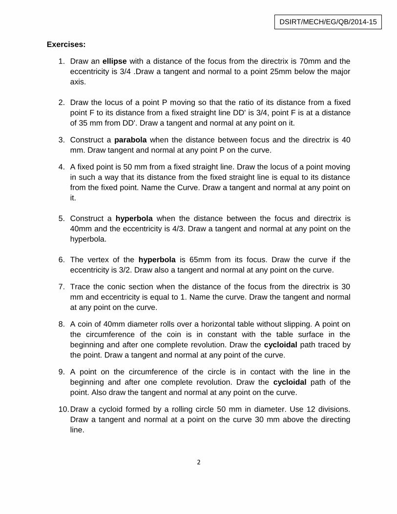
Symbol for projection method:
First angle projection method is to be followed in engineering drawing.
2
DSIRT/MECH/EG/QB/2014-15
Exercises:
1. Draw an ellipse with a distance of the focus from the directrix is 70mm and theeccentricity is 3/4 .Draw a tangent and normal to a point 25mm below the majoraxis.
2. Draw the locus of a point P moving so that the ratio of its distance from a fixedpoint F to its distance from a fixed straight line DD' is 3/4, point F is at a distanceof 35 mm from DD'. Draw a tangent and normal at any point on it.
3. Construct a parabola when the distance between focus and the directrix is 40mm. Draw tangent and normal at any point P on the curve.
4. A fixed point is 50 mm from a fixed straight line. Draw the locus of a point movingin such a way that its distance from the fixed straight line is equal to its distancefrom the fixed point. Name the Curve. Draw a tangent and normal at any point onit.
5. Construct a hyperbola when the distance between the focus and directrix is40mm and the eccentricity is 4/3. Draw a tangent and normal at any point on thehyperbola.
6. The vertex of the hyperbola is 65mm from its focus. Draw the curve if theeccentricity is 3/2. Draw also a tangent and normal at any point on the curve.
7. Trace the conic section when the distance of the focus from the directrix is 30mm and eccentricity is equal to 1. Name the curve. Draw the tangent and normalat any point on the curve.
8. A coin of 40mm diameter rolls over a horizontal table without slipping. A point onthe circumference of the coin is in constant with the table surface in thebeginning and after one complete revolution. Draw the cycloidal path traced bythe point. Draw a tangent and normal at any point of the curve.
9. A point on the circumference of the circle is in contact with the line in thebeginning and after one complete revolution. Draw the cycloidal path of thepoint. Also draw the tangent and normal at any point on the curve.
10.Draw a cycloid formed by a rolling circle 50 mm in diameter. Use 12 divisions.Draw a tangent and normal at a point on the curve 30 mm above the directingline.
3
DSIRT/MECH/EG/QB/2014-15
11.Construct an epicycloids generated by a rolling circle of diameter 50mm anddirecting circle of diameter 150mm. Draw the tangent and normal to the curve atany point of the epicycloids.
12.A coir is unwound from a drum of 30mm diameter. Draw the locus of the free endof the coir for unwinding through an angle of 360º. Draw the tangent and normalto the curve at a distance of 50 mm from the centre of the circle.
13.An in elastic string of 150mm long has its one end attached to thecircumference of a circular disc of 40mm diameter. Draw the curve traced out bythe other end of the string when it is completely wound around the disc keepingthe string always tight. Name the curve obtained. Draw the tangent and normal tothe curve at a point distant 100mm from the centre of the disc.
14.Draw on involute of a square of side 30 mm. Draw the tangent and normal atany point on the curve.
15.Draw on involute of a circle of diameter 40 mm. Also draw the tangent andnormal at any point on the curve.
16.A coin 30 mm diameter rolls in a straight line on a table plot and name the locusof a point lying on the circumference.
4
DSIRT/MECH/EG/QB/2014-15
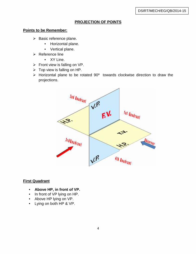
PROJECTION OF POINTS
Points to be Remember:
Basic reference plane. Horizontal plane. Vertical plane.
Reference line XY Line.
Front view is falling on VP. Top view is falling on HP. Horizontal plane to be rotated 90º towards clockwise direction to draw the
projections.
First Quadrant
Above HP, in front of VP. In front of VP lying on HP. Above HP lying on VP. Lying on both HP & VP.
5
DSIRT/MECH/EG/QB/2014-15
Second Quadrant
Above HP, behind VP. Behind VP Lying on HP. Above HP lying on VP. Lying on both HP & VP.
Third Quadrant
Below HP, behind VP. Below HP Lying on VP. Behind VP Lying on HP. Lying on both HP & VP.
Fourth Quadrant
Below HP, in front of VP. In front of VP Lying on HP. Below HP Lying on VP. Lying on both HP & VP.
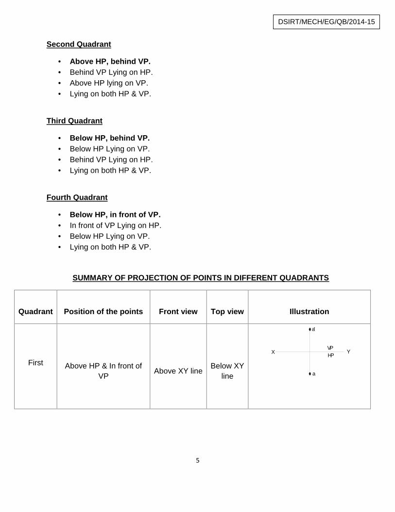
SUMMARY OF PROJECTION OF POINTS IN DIFFERENT QUADRANTS
Quadrant Position of the points Front view Top view Illustration
First Above HP & In front ofVP Above XY line Below XY
line
a'
a
VPHPX Y
b'b
VP,HPX Y
c
c'
HPVPX Y
d
d'
VP,HPX Y
6
DSIRT/MECH/EG/QB/2014-15
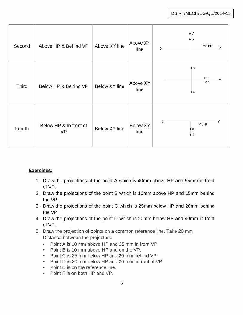
Second Above HP & Behind VP Above XY line Above XYline
a'
a
VPHPX Y
b'b
VP,HPX Y
c
c'
HPVPX Y
d
d'
VP,HPX Y
Third Below HP & Behind VP Below XY line Above XYline
a'
a
VPHPX Y
b'b
VP,HPX Y
c
c'
HPVPX Y
d
d'
VP,HPX Y
Fourth Below HP & In front ofVP Below XY line Below XY
line
a'
a
VPHPX Y
b'b
VP,HPX Y
c
c'
HPVPX Y
d
d'
VP,HPX Y
Exercises:
1. Draw the projections of the point A which is 40mm above HP and 55mm in frontof VP.
2. Draw the projections of the point B which is 10mm above HP and 15mm behindthe VP.
3. Draw the projections of the point C which is 25mm below HP and 20mm behindthe VP.
4. Draw the projections of the point D which is 20mm below HP and 40mm in frontof VP.
5. Draw the projection of points on a common reference line. Take 20 mmDistance between the projectors. Point A is 10 mm above HP and 25 mm in front VP Point B is 10 mm above HP and on the VP. Point C is 25 mm below HP and 20 mm behind VP Point D is 20 mm below HP and 20 mm in front of VP Point E is on the reference line. Point F is on both HP and VP.
7
DSIRT/MECH/EG/QB/2014-15
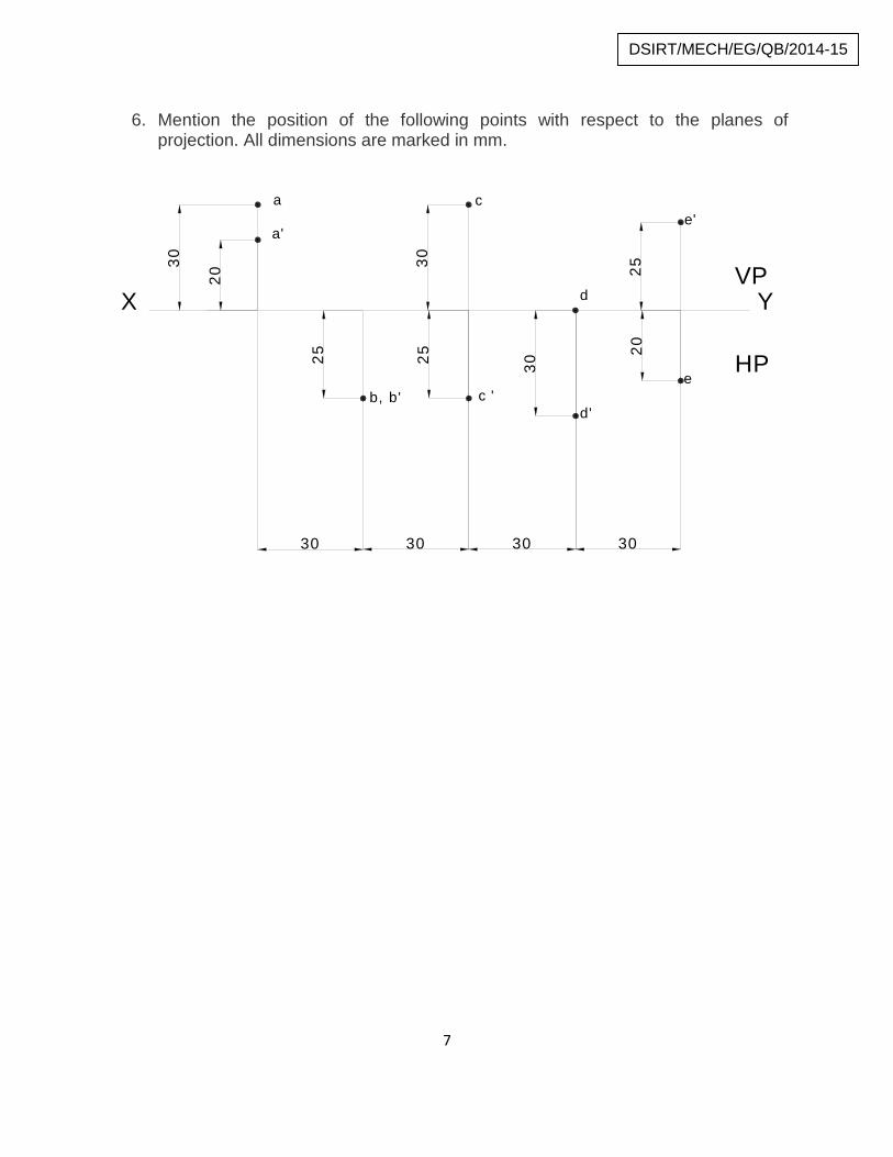
6. Mention the position of the following points with respect to the planes ofprojection. All dimensions are marked in mm.
25
3025 30
2520
20
30
30 30 30 30
X Y VP
HP
a
a'
b, b'
c
c 'd'
e
e'
d
8
DSIRT/MECH/EG/QB/2014-15
PROJECTION OF STRAIGHT LINES
TYPES:
Type 1: line perpendicular to HP and parallel to VP.Type 2: line perpendicular to VP and parallel to HP.Type 3: line parallel to both HP and VP.Type 4: line inclined to HP and parallel to VP.Type 5: line inclined to HP and lies on VP.Type 6: line inclined to VP and lies on HP.Type 7: line inclined to VP and parallel to HP.Type 8: line inclined to both HP and VP.
Exercises:
1. A Straight line AB, 60 mm long is perpendicular to the HP and parallel to VP. Theline is 20 mm in front of VP. The end A nearer to the HP is 25 mm above HP. drawthe projections of the line.
2. A Straight line PQ 50 mm long is perpendicular to the VP and parallel to the HP.The line has its end P 20 mm long above HP. And 25 mm in front of VP. Draw itsprojections.
3. A straight line PQ 60 mm long is kept parallel to both HP and VP. One end of theline P is 20 mm above HP, 20 mm in front of VP. Draw the projections of the line.
4. A straight line AB, 40 mm long is inclined at 30º to HP and parallel to VP. The endA of line is 20 mm above HP and 15 mm in front of VP. Draw the projection of theline
5. A line AB 60 mm long having one of its ends A at 10 mm above HP and 15 mm infront of VP is inclined to HP and parallel to VP. The top view of line measures 45mm. Draw the projections of the line. Determine its inclination with HP.
6. A line AB 60 mm long is lying on VP and inclined at 45º to HP. The end A is 20 mmabove HP. draw its projections.
7. A line AB 75 mm long is lying on the HP and makes an angle of 30º with VP. Its endA is 25 mm in front of VP. Draw the projections of the line.
9
DSIRT/MECH/EG/QB/2014-15
8. A straight line RS 50 mm long is parallel to HP and inclined at an angle of at anangle of 30º to VP. The end R is 25 mm above HP and 20 mm in front of VP. Drawthe projections of the line.
9. The front view of a line 75 mm long measures 55 mm. the line is parallel to HP andone of its end is in the VP and 25 mm above the HP. Draw the projections of the lineand determine its inclination with the VP
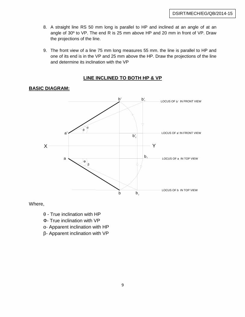
LINE INCLINED TO BOTH HP & VP
BASIC DIAGRAM:
a'
a
b b2
b' b'1
b'2
b1
X Y
LOCUS OF IN FRONT VIEWb'
LOCUS OF a' IN FRONT VIEW
LOCUS OF a IN TOP VIEW
LOCUS OF b IN TOP VIEW
Where,
θ - True inclination with HPФ- True inclination with VPα- Apparent inclination with HPβ- Apparent inclination with VP
10
DSIRT/MECH/EG/QB/2014-15
POINTS TO REMEMBER
Line XY – Reference line. Dimensioning should be in the left corner of the drawing and must be in same vertical
line, 20 mm away from the actual line. No two lines should cross each other, particularly dimension line. Locus of a, a', b, b' must be written in the right corner of the drawing and in running
letters. Direction of rotation must be clearly indicated with arrows. Points above HP – Should be marked above reference line. Points in front of VP –Should be marked below reference line. a' b' and a b – Projection of the line a'b'1 and ab2 – True length of the line a' b' = b' b2' – Front view a b = a b1 – Top view line joining a and a’ and line joining b and b’ are known as projectors b, b2 will lie on same locus line b b', b1' will lie on same locus line b' The angle made with true length is known as true inclination a, b1 will lie on same locus line a a’, b2' will lie on same locus line a' The distance between a a’ and bb’ is called end projector distance Dimension line should be marked at a distance of 20 mm from the object line
Exercise:
1. A Straight line AB of 75 mm long is inclined at 30º to HP & 45º to VP. The ends Ais 15 mm in front of VP and 20 mm above HP. Draw the projections of line & findits apparent inclinations.
2. A line AB 80 mm long has its end A 60 mm in front of VP & 15 mm above HP.The line is inclined at 50º to HP and 40º to VP. Draw the projections of lines.
3. A Straight line 85 mm long has one end 15 mm in front of VP and 10 mm aboveHP, while the other end is 50 mm in front of VP and 45 mm above HP. Draw theplan and elevation of the line. Determine the inclinations of the line to HP andVP.
4. A Straight line 70 mm long has one end 15 mm in front of VP and 50 mm aboveHP, while the other end is 35 mm in front of VP and 20 mm above HP. Draw theplan and elevation of the line.
11
DSIRT/MECH/EG/QB/2014-15
5. A line AB 75 mm long has one of its ends 60 mm in front of VP & 20 mm aboveHP. The other end is 20 mm in front of VP & is above HP. The top view of line is55 mm long. Draw the front view.
6. A line measuring 80 mm long has one of its ends 60 mm above HP and 20 mm infront of VP .The other end is 15 mm above HP and in front of VP. The front viewof the line is 60 mm long. Draw the top view.
7. A line AB 60 mm long has its end A 30 mm above HP and 25 mm in front of VP.The top view and front view has a length of 40 mm and 50 mm respectively.Draw its projections.
8. One end P of a line PQ 80 mm long is 10 mm above HP and 15 mm in front ofVP. The line is inclined at 40º to HP & the top view makes 50º with VP. Draw theprojections & find the true inclination with VP.
9. A straight line AB 80 mm long has its end A 20 mm above HP & 30 mm in front ofVP. It appears to make an angle of 40º with HP & a plan length of 65 mm. Drawthe projections & find the true inclination with HP and VP.
10.A line PQ measuring 75 mm long has one of its ends 50 mm in front of VP & 15mm above HP. The top view of line is 50 mm long. Draw and measure the frontview. The other end is 15 mm in front of VP & is above HP. Determine the trueinclinations of the line.
11.A line QR has its end Q 20 mm above HP & 25 mm in front of VP. The other endR is 45 mm above HP & 55 mm in front of VP. Distance between the endprojectors is 60 mm. Draw its projections & also find the true length & trueinclinations of the line with HP & VP by the Rotating Plane method.
12.A line AB has its end A 15 mm above HP and 20 mm in front of VP. The end B is60 mm above HP and the line is inclined at 30º to HP. The distance between theend projectors of the line is 55 mm. Draw its projections & find inclinations withVP.
13.The plan of a line PQ makes an angle of 30º with the horizontal and having alength of 90 mm. the end Q is in the HP and P is in the VP and 65 mm above theHP. Draw the projections of the line and find its true length and true inclinationswith the HP and VP (θ, Ф).
14.The mid-point of the straight line AB is 60 mm above HP and 50 mm in front ofVP the line measures 80 mm long and inclined at 30º to HP and 45º to VP. Drawthe projections.
12
DSIRT/MECH/EG/QB/2014-15
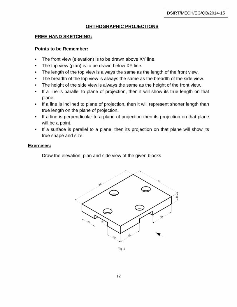
ORTHOGRAPHIC PROJECTIONS
FREE HAND SKETCHING:
Points to be Remember:
The front view (elevation) is to be drawn above XY line. The top view (plan) is to be drawn below XY line. The length of the top view is always the same as the length of the front view. The breadth of the top view is always the same as the breadth of the side view. The height of the side view is always the same as the height of the front view. If a line is parallel to plane of projection, then it will show its true length on that
plane. If a line is inclined to plane of projection, then it will represent shorter length than
true length on the plane of projection. If a line is perpendicular to a plane of projection then its projection on that plane
will be a point. If a surface is parallel to a plane, then its projection on that plane will show its
true shape and size.
Exercises:
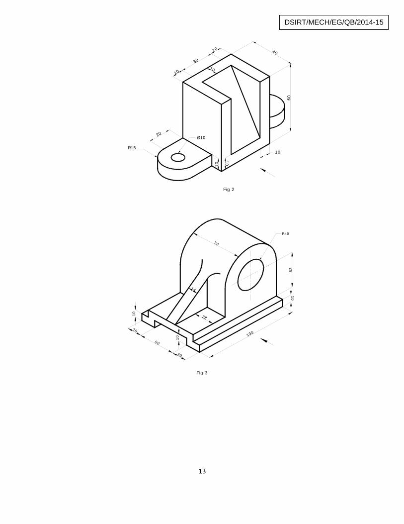
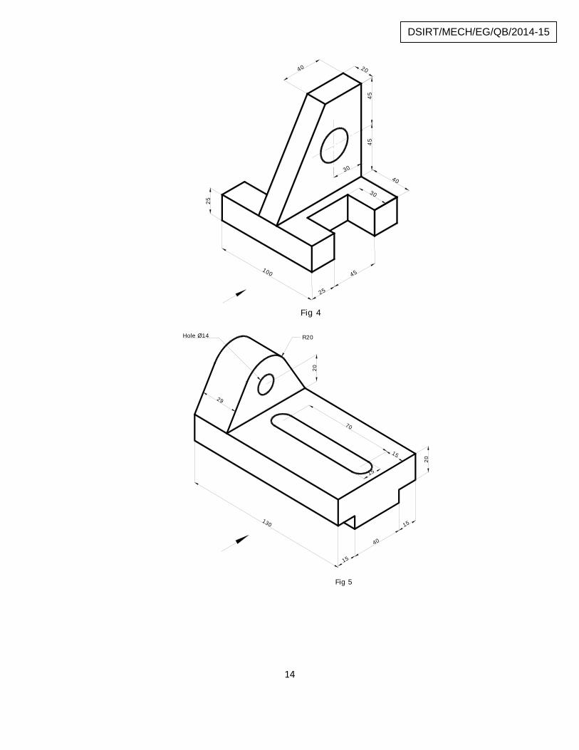
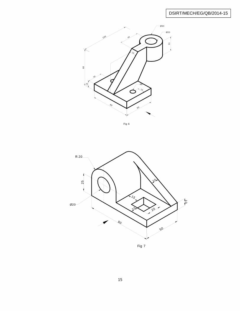
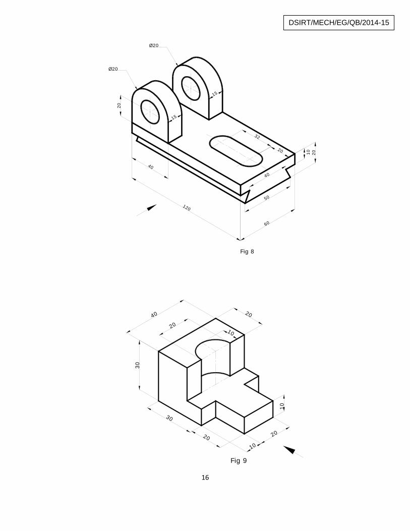
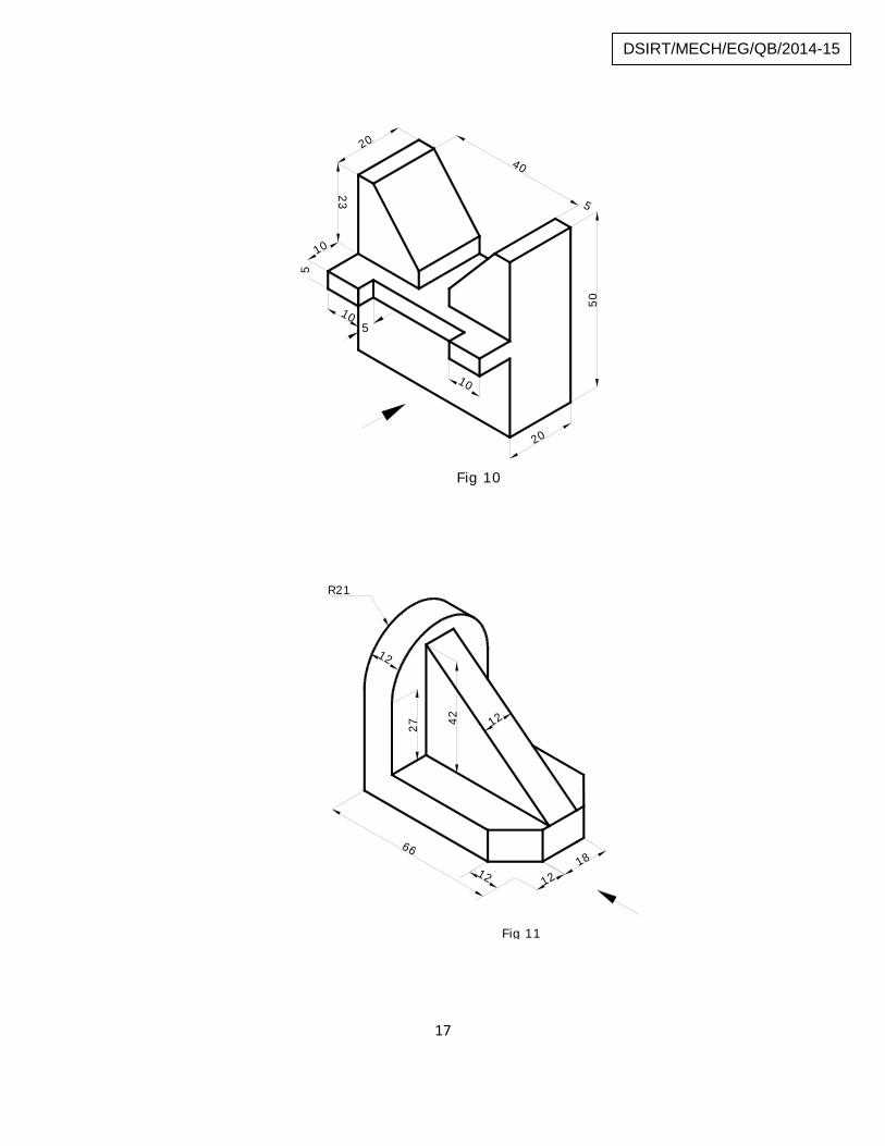
Draw the elevation, plan and side view of the given blocks
60
80
10
30
3020
20 5
Fig 1
13
DSIRT/MECH/EG/QB/2014-15
40
60
10
30
10
20
10
10
10
10
Ø10
R15
Fig 2
130
10
10
50
20
20
10
14
70
62
28
R40
Fig 3
14
DSIRT/MECH/EG/QB/2014-15
30
40
45
25
100
25
40 20
45
30
45
Fig 420
20
15
40
15
130
70
15
15
29
R20Hole Ø14
Fig 5
15
DSIRT/MECH/EG/QB/2014-15
6080
15
40
31
15
15
30
Ø20
Ø40
100
80R5
Fig 6
90
50
25
10
10
15
10 20Ø20
R 20
Fig 7
16
DSIRT/MECH/EG/QB/2014-15
60
20
15
15
120
40
20
32
10 20
Ø20
Ø20
40
50
Fig 8
30
30
20 20
10
10
10
20
2040
Fig 9
17
DSIRT/MECH/EG/QB/2014-15
5
40
20
23
10
5
10
50
20
510
Fig 10
1218
4227
12
12
12
66
R21
Fig 11
18
DSIRT/MECH/EG/QB/2014-15
PROJECTION OF PLANES
Points to be Remember:
Plane figures or surfaces have only two dimensions, viz. length and breadth.They do not have thickness.
Exercise:
1. A thin rectangular plate of side 40 mm x 20 mm has its shorter side in the HP andinclined at angle of 30o to VP. Project its front view when its top view is a perfectsquare of 20 mm side.
2. A circular lamina of 60 mm diameter rests on HP on a point 1 on thecircumference. The lamina is inclined to HP such that the top view of it’s anellipse of minor axis 35 mm. The top view through the point 1 makes an angle of45o with VP. Draw the projections. Determine the angle made by the lamina withthe VP.
3. A rectangular aluminum plate of size 63 mm x 36 mm with negligible thicknesshas one of its shorter edges in the VP and inclined at 40o to HP. Its front view is asquare of side 36 mm. Draw the top view.
4. A pentagon of side 30 mm rests on ground on one of its corners with the sidescontaining the corner being equally inclined to the ground. The side opposite tothe corner on which it rests is inclined at 30o to VP and is parallel to the HP. Thesurface of the pentagon makes 50o with the ground. Draw the top and front viewsof the pentagon.
5. A square lamina ABCD of side 40 mm rests on the ground on its corner A in sucha way that the diagonal AC is inclined 45o to the HP and apparently inclined at30o to the VP. Draw its projections.
6. A regular hexagonal lamina of 30 mm. side rests on one of its edges upon HP. Itsplane is inclined at 450 to HP and the edge on which it rests is inclined at 300 toVP. Draw its projections.
7. A circular lamina of 50 mm diameter inclined at 300 to HP and perpendicularto VP has its center 30 mm in front of VP & on HP. Draw front & top views.
19
DSIRT/MECH/EG/QB/2014-15
8. A regular hexagonal lamina of side 30 mm has a side in both HP & VP, while thelamina makes an angle of 60º with VP. Draw its front and top views.
9. A Square plane of side 40 mm has its surface parallel to VP and perpendicular toHP. Draw its projections when one of the sides is inclined at 30° to HP.
10.A Circular plane of diameter 50 mm has its surface parallel to HP andperpendicular to VP. Its Centre is 20 mm above HP and 30 mm in front of VP.Draw its projections.
11.A Pentagonal lamina of side 30 mm is placed with one side on HP and thesurface inclined at 50° to HP and perpendicular to VP. Draw its projections.
20
DSIRT/MECH/EG/QB/2014-15
PROJECTION OF SOLIDS
Points to be Remember:
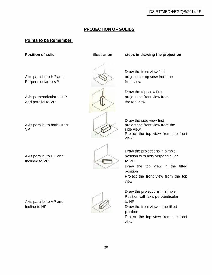
Position of solid illustration steps in drawing the projection
Draw the front view firstAxis parallel to HP and project the top view from thePerpendicular to VP front view
Draw the top view firstAxis perpendicular to HP project the front view fromAnd parallel to VP the top view
Draw the side view firstAxis parallel to both HP & project the front view from theVP side view.
Project the top view from the frontview.
Draw the projections in simpleAxis parallel to HP and position with axis perpendicularInclined to VP to VP.
Draw the top view in the tiltedpositionProject the front view from the topview
Draw the projections in simplePosition with axis perpendicular
Axis parallel to VP and to HPIncline to HP Draw the front view in the tilted
positionProject the top view from the frontview
21
DSIRT/MECH/EG/QB/2014-15
Exercise:
1. Draw the projections of a hexagonal pyramid of 90 mm height and of side 30 mmwhen one triangular face of the pyramid is vertical to HP.
2. Draw the projections of a square pyramid of 40 mm side and axis 60 mm longwhen it lies on the H.P. with its slant edge and axis parallel to V.P.
3. A hexagonal prism of side of base 25 mm and axis 60 mm rests on a corner ofits base in H.P. with the axis of the prism inclined at 40º to H.P. and parallel toV.P. Draw its projections.
4. Draw the projections of a hexagonal prism of base side 20 mm and axis length50 mm when it is lying on the ground on one of its rectangular faces and the axisis inclined at 35º to V.P.
5. Draw the projections of a cylinder of diameter 50 mm and axis length 80 mmwhen it is lying on the ground with its axis inclined at 45º to V.P. and parallel tothe ground.
6. A square pyramid of base side 30 mm, axis length 50 mm has one of itstriangular faces in the V.P. and the axis parallel to HP and 25 mm above the H.P.Draw its projections.
7. A square prism of base 35 mm and axis length 60 mm lies on the H.P. on one ofits longer edges with its faces equally inclined to the H.P. Draw its projectionswhen its axis is inclined at 30º to the V.P.
8. A hexagonal prism of base side 30 mm and axis length 60 mm rests on the H.P.on one of its base edges with its axis inclined at 60º to the H.P. and parallel toV.P. Draw its top view and front view.
9. Draw the projections of a cube of side 40 mm when it rests on the ground on oneof its corners and a face containing that corner is inclined at 30º to the groundand perpendicular to the V.P.
10.Draw the projections of a cube of side 40 mm when it rests on one of its cornerswith a diagonal of the solid vertical.
22
DSIRT/MECH/EG/QB/2014-15
11.Draw the projections of hexagonal prism of base side 20 mm and axis length 50mm when it rests on the ground on one of the edges of the base and the axisinclined at 35º to the ground and parallel to the V.P.
12.A cylinder of diameter 30 mm and axis length 50 mm is resting on the H.P. on apoint so that its axis is inclined at 45º to the H.P. and parallel to the V.P. Draw itstop view and front view.
13.A hexagonal pyramid of base edge 40 mm and altitude 80 mm rests on one of itsbase edges on the H.P. with its axis inclined at 30º to the H.P. and parallel to theV.P. Draw its top view and front view.
14. A square pyramid of base side 60 mm and altitude 100 mm lies on the H.P. onone of its triangular faces with its axis parallel to the V.P. Draw its projections.
15.A cone of base diameter 40 mm and altitude 80 mm rests on the H.P. with itsaxis inclined at 30º to the H.P. and parallel to V.P. Draw its top view and frontview.
16.A hexagonal prism base side 25 mm and axis length 60 mm lies with one of itsrectangular faces on the H.P. such that its axis is inclined at 45º to the V.P. Drawits projections.
17.A hexagonal pyramid of base edge 25 mm and altitude 50 mm rests with its baseon H.P. such that one of the edges of the base is inclined at 20º to V.P. Draw itstop view and front view.
18. A pentagonal prism side of base 25 mm and axis 50 mm long rests with one ofits shorter edges on H.P. such that the base containing that edge makes anangle of 30º to H.P. and its axis is parallel to V.P. Draw its projections.
19.A hexagonal pyramid of base edge 25 mm and altitude 50 mm lies with one of itstriangular faces on the H.P. and its axis parallel to V.P. Draw its projections.
20.Draw the projections of a pentagonal prism side of base 30 mm and axis 65 mmlong lying on one of its longer edges on H.P. with one rectangular faceperpendicular to H.P. such that the axis makes 60º with V.P.
23
DSIRT/MECH/EG/QB/2014-15
21.A hexagonal prism of base side 25 mm and axis length 50 mm rests with one ofits base corner on H.P. such that its base makes an angle of 60º to H.P. and itsaxis parallel to V.P. Draw its projections.
22.A pentagonal pyramid, side of base 25 mm and axis 55 mm long, lies with one ofits slant edges on H.P. such that its axis is parallel to V.P. Draw its projections.
23.Draw the projection of a square pyramid of base 40 mm side and axis 70 mmlong, when the solid lies with one of its slant edges on HP and the vertical planepassing through that slant edge and axis makes 30º with VP.
24.A pentagonal pyramid, with base 35 mm side and height 70 mm rest on oneedge of its base on HP so that the highest point on the base is 25 mm above HP.Draw its projection, when the axis is parallel to VP. Draw another front view, on areference line inclined at 45º to the edge on which it is resting so that the base isvisible.
25.Draw the plan and elevation of a right regular pentagonal prism side of base 25mm and axis 58 mm long when it is resting on its base on HP with one of itsrectangular faces making an angle of 30º to VP.
24
DSIRT/MECH/EG/QB/2014-15
SECTION OF SOLIDS
Points to be Remember:
The section lines are usually drawn at 45º to the horizontal. Section lines should be equally spaced. The major portion of the solid should be retained for projections and shown by
thick lines in both front and top views. Section plane is parallel to VP - the true shape of the section is obtained in the
front view. Section plane is parallel to HP and perpendicular to VP - the true shape of the
section is obtained in the top view. Section plane is inclined to HP - sectional view obtained on HP is not the true
shape of the section and it is called apparent section. Section plane is perpendicular to both HP and VP then the side view shows the
true shape.
Exercise:
1. A cube of side 30 mm rests on the HP on its end with the vertical faces equallyinclined to the VP. It is cut by a plane perpendicular to the VP and inclined at 30°to HP meeting the axis at 25 mm above the base. Draw its front view, sectionaltop view and true shape of the section.
2. A cube of 45 mm side rests with a face on H.P. such that one of its vertical faceis inclined 30° to V.P. A section plane is parallel to V.P. cuts the cube at adistance of 15 mm from the vertical edge nearer to the observer. Draw its top andsectional front views.
3. A cylinder of diameter 50 mm and height 60 mm rests on its base on H.P. It is cutby a plane perpendicular to V.P. and inclined at 45° to H.P. The cutting planemeets the axis at a distance of 15 mm from the top. Draw the sectional plan andtrue shape of the section.
4. A cone of base diameter 50 mm and altitude 60 mm rests on its base on the HP.It is cut by a plane perpendicular to the VP and inclined at 40° to the HP. Thecutting plane meets the axis at 30 mm from the vertex .Draw the sectional topview.
5. A cone of base diameter 50 mm and altitude 60 mm rests on its base on the HP.It is cut by a plane perpendicular to the VP and parallel to one of the extreme
25
DSIRT/MECH/EG/QB/2014-15
generators, 10 mm away from it .Draw the sectional top view and the true shapeof the section.
6. A right circular cone of base diameter 50 mm and axis length 60 mm rests on itsbase on the H.P. It is cut by a plane perpendicular to the H.P and inclined at 600
to the VP. The shortest distance between the cutting plane and the top view ofthe axis is 8 mm. Draw the top view, sectional front view and the true shape ofthe section.
7. A square pyramid of base side 25 mm and altitude 40 mm rests on the HP on itsbase with the base edges equally inclined to the VP. It is cut by a planeperpendicular to the VP and inclined at 300 to the HP meeting the axis at 21 mmabove the HP .Draw the sectional top view and the true shape of the section.
8. A hexagonal prism of side of base 20 mm and length 60 mm rests on HP with itsaxis being vertical and one edge of its base inclined 150 to VP. The solid is cut bya plane perpendicular to VP and inclined at 400 to HP and bisecting the axis ofthe prism. Draw the projections of the prism and true shape of the section.
9. A pentagonal pyramid of base side 20 mm and altitude 55 mm rests on its baseon HP with one base edge being perpendicular to VP. It is cut by a plane inclinedat 500 to base. The cutting plane meets the axis at 15 mm above the base. Drawthe front view, sectional top view and true shape of the section.
10.A hexagonal pyramid of base side 25 mm and axis 55 mm rests on its base onHP with two base edges perpendicular to VP. It is cut by a plane perpendicular toVP and inclined at 300 to HP, meeting the axis at 20 mm from the vertex. Draw itsfront view, sectional top view and true shape of the section.
11.A hexagonal pyramid of base side 25 mm and axis 70 mm long has thehexagonal end on VP, with two of its edges perpendicular to HP. A sectionalplane perpendicular to VP and inclined at 300 to HP cuts the pyramid at a point8mm from the axis and above it. Draw the sectional top view. Also find the trueshape of the cut portion, by suitable construction.
12.A hexagonal pyramid of base side 25 mm and axis 70 mm rests on its base onHP with two base sides parallel to VP. It is cut by a plane perpendicular to VPand inclined at 300 to HP, meeting the axis at 20 mm from the vertex. Draw itsfront view, sectional top view and true shape of the section.
26
DSIRT/MECH/EG/QB/2014-15
13.A hexagonal pyramid of base 30 mm and axis 70 mm lies on HP on its baseedge such that one of the slant faces is perpendicular to both the planes. Drawits projections. When it is cut by a section plane parallel to HP at a distance of 15mm from apex point.
14.A right circular cone diameter of base 56 mm and height 65 mm rests on its baseon HP. A section plane perpendicular to VP and inclined to HP at 450 cuts thecone meeting its axis at a distance of 36 mm from its base. Draw its front view,sectional top view and true shape of the section.
15.A pentagonal pyramid, side of base 30 mm and axis 60 mm long rests with itsbase on HP and edge of its base is parallel to VP. A sectional planeperpendicular to VP and inclined 450 HP passes through the axis at a point 35mm above the base. Draw the sectional top view.
16.A square prism, side of base 30 mm and axis 60 mm long, rests with its base onHP and one of its rectangular faces is inclined at 300 to VP. A sectional planeperpendicular to VP.A sectional plane perpendicular to VP and inclined 60° to HPcuts the axis of the prism at a 20 mm from its top end. Draw the sectional topview.
17.A cube of 70 mm long an edge has its vertical faces equality inclined to the VP. Itis by an axially inclined plane in such a way that the true shape of the cut part isa regular hexagon. Determine the inclination of the cutting plane with the HP.Draw the front view, sectional top view and true shape of the section.
18.A vertical cylinder 40 mm diameter is cut by a vertical section plane making 300
to VP in such a way that the true shape of the section is a rectangle of 25 mmand 60 mm sides. Draw the projections and true shape of the section.
19.A cylinder of diameter 60 mm and height 80 mm is lying on the HP with the axisparallel to both the HP and the VP.A vertical plane inclined at 250 to the VP cutsthe cylinder and passes through the midpoint of the axis. Draw the sectional frontview.
27
DSIRT/MECH/EG/QB/2014-15
DEVELOPMENT OF SURFACES
Points to remember:
The development is the true representation of the surfaces of the object it isobtained through true length only.
It is not possible to spread the doubly curved surface on any plane one has to becontented by their approximant development only.
Exercise:
1. A lamp shade is formed by cutting a cone of base 144 mm diameter and 174 mmheight by a horizontal plane at a distance of 72 mm from the apex and anotherplane inclined at 300 to HP passing through one extremity of the base. Draw thedevelopment of the shade.
2. A cone of 60 mm base diameter has a height of 80 mm. A hole 30 mm diameteris made through the cone. The center of hole is 20 mm above the base and lieson the elevation of the cone axis. Draw the development of the cone and showthe development of the hole on it.
3. A square pyramid of base side 25 mm and altitude 65 mm rests on the HP on itsbase with the base edges equally inclined to VP. It is cut by a planeperpendicular to VP and inclined at 300 to HP meeting the axis at 25 mm aboveHP. Draw the development of the lateral surface of the square pyramid.
4. A hexagonal prism of side of base 30 mm and axis 75 mm long is resting on itsbase on HP such that a rectangular face is parallel to VP. It is cut by a sectionplane, perpendicular to VP and inclined at 300 to HP. The section plane ispassing through the top end of an extreme lateral edge of the prism. Draw thedevelopment of the lateral surface of the cut prism.
5. A hexagonal prism of base side 30mm and axis length 60mm is resting on HP onits base with two of its vertical faces perpendicular to VP. It is cut by a planeinclined at 500 to HP and perpendicular to VP and meets the axis of prism at adistance 10mm from the top end. Draw the development of the lateral surface ofthe prism.
28
DSIRT/MECH/EG/QB/2014-15
6. A Pentagonal pyramid, side of base 30mm and height 52mm stands with its baseon HP and an edge of the base is parallel to VP and nearer to it. It is cut by aplane perpendicular to VP, inclined at 400 to HP and passing through a point onthe axis, 32mm above the base. Draw the sectional top view. Develop the lateralsurfaces of the truncated pyramid.
7. A hexagonal prism of side of base 24mm and axis 64mm is on HP on one of itsends with a base edge parallel to VP. A square hole of side 26mm is drilled suchthat the axis of the hole is perpendicular to VP and bisects the axis of the prismwith all the faces equally inclined to HP. Draw the development of the lateralsurfaces of the prism showing the true shape of the hole.
8. A cylinder of 60mm diameter and axis 80mm long is standing on its base on HP.A horizontal square hole of 35mm side is cut through the cylinder such that theaxis of the hole is parallel to HP and bisects the axis of the cylinder. A side faceof the hole is inclined at 200 to HP. Develop the lateral surface of the cylinderwith the square hole.
9. A right regular Pentagonal prism, base edge 24mm and altitude 60mm stands onits base on HP such that one of its base edges is parallel to VP and nearer to theobserver. Through the center of the rectangular face containing the base edge, ahole of 28mm diameter is drilled through, such that the hole axis is horizontal.Draw the development of the lateral surfaces of the prism with the hole on it.
10.A regular Pentagonal pyramid of side of base 24mm and axis 60mm long standson its base on HP with one of the sides of the base parallel to VP and nearer toit. A square cutout of 15mm side is drilled through it such that its axis is parallelto HP and perpendicular to VP. The axis of the cutout intersects the axis of thepyramid at a distance of 15mm from the base. The faces of the cutout are equallyinclined to HP. Develop the lateral surfaces of the pyramid with the cutout.
11.A right circular cone of base 60mm diameter and 60mm height stands verticallywith its base on HP. A semi-circular hole of 36mm diameter is cut through thecone such that axis of the hole is parallel to HP, perpendicular to VP andintersecting the axis of the cone 20mm above the base. The flat surface of thehole is parallel to HP and perpendicular to VP. Draw the development of thelateral surface of the cone with the hole.
29
DSIRT/MECH/EG/QB/2014-15
12.A cylinder of 60mm diameter and axis 80mm long stands with its base on HP. Itis completely penetrated by a horizontal cylinder of 45mm diameter and axis80mm long such that their axes bisect each other at right angles. The axis of thepenetrating cylinder is parallel to VP. Draw the development of the lateralsurfaces of the two intersecting cylinders.
13.A square prism of base side 30mm and axis length 60mm is resting on HP onone of its faces with a base side inclined at 30 to VP. It is cut by plane inclined at400 to HP and perpendicular to VP and is bisecting the axis of the prism. Draw itsdevelopment.
14.A cylinder of base diameter 45mm and height 65mm lies on its base on HP. It iscut by a plane perpendicular to VP and inclined at 300 to HP. And meeting theaxis at a distance of 30mm from the base. Draw the development of the lowerportion of the solid.
15.A cone of base diameter 50mm and axis length 75mm is resting on HP on itsbase. It is cut by a plane inclined at 450 to HP and perpendicular to VP and isbisecting the axis. Draw the development of the lower portion of the solid.
16.A pentagonal pyramid of base side 30mm and axis length 60mm is resting on HPon its base with a side parallel to VP. It is cut by a plane inclined at 400 to HP andperpendicular to VP and passing through a point at a distance of 15mm from thebase. Draw the development of the lower portion of the solid.
17.A square prism of base side 30mm and axis length 60mm is resting on HP onone of its faces with a base side inclined at 30 to VP. It is cut by plane inclined at400 to HP and perpendicular to VP and is bisecting the axis of the prism. Draw itsdevelopment
18.A hexagonal prism of base side 30mm and axis length 60mm is resting on HP onits base with two of the vertical faces perpendicular to VP. It is cut by a planeinclined at 500 to HP and perpendicular to VP and passing through a point at adistance of 10mm from the top face. Draw the development of the lower portionof the solid.
19.A cylinder of base diameter 45mm and height 65mm lies on its base on HP. It iscut by a plane perpendicular to VP and inclined at 300 to HP. And meeting theaxis at a distance of 30mm from the base. Draw the development of the lowerportion of the solid.
30
DSIRT/MECH/EG/QB/2014-15
20.A cone of base diameter 50mm and axis length 75mm is resting on HP on itsbase. It is cut by a plane inclined at 450 to HP and perpendicular to VP and isbisecting the axis. Draw the development of the lower portion of the solid.
21.A pentagonal pyramid of base side 30mm and axis length 60mm is resting on HPon its base with a side parallel to VP. It is cut by a plane inclined at 400 to HP andperpendicular to VP and passing through a point at a distance of 15mm from thebase. Draw the development of the lower portion of the solid.
31
DSIRT/MECH/EG/QB/2014-15
ISOMETRIC PROJECTION
Points to remember:
The sides of the cube and all planes parallel to them are isometric planes. Axes X, Y and Z form 120º angles between one another. The vertical axis is equal to the real height. A 30º- 60º set square is used to trace the isometric lines.
Exercise:
1. A hollow cylinder of base 50 mm diameter and axis 70 mm long has a squarehole of 20 mm side. The axis of the cylinder and the hole coincide. Draw thethree possible ways of representing the isometric projection of the solid.
2. Draw the isometric projection of a hexagonal pyramid of side of base 30 mm andheight 75 mm, when it is resting on HP such that an edge of the base is parallelto VP.
3. A pentagonal pyramid, 30 mm edge of base and 65 mm height, stands on HPsuch that an edge of the base is parallel to VP and nearer to it, a section planeperpendicular to VP and inclined at 30 degree to HP cuts the pyramid passingthrough a point on the axis at a height of 35 mm from the base. Draw theisometric projection of the truncated pyramid showing the cut surface.
4. A cylinder of 60 mm diameter and 70 mm height stands on HP. A section planeperpendicular to VP and inclined at an angle of 45 degree to HP bisects the axis.Draw the isometric projection of the truncated cylinder, showing the cut surface.
5. A pentagonal pyramid of 40 mm edge of base and height 70 mm reset with itsbase edges is perpendicular to VP and lies on the right of the axis of the pyramid.A section plane perpendicular to VP and inclined at 30 degree to HP cuts theaxis of the pyramid at a point 30 mm above the base of the pyramid. Draw theisometric projection of the truncated pyramid.
32
DSIRT/MECH/EG/QB/2014-15
6. A hexagonal prism, side of base 25 mm and height 50mm rests on HP and oneof the edges of its base is parallel to VP, A section plane perpendicular to VP andinclined at 50 degree to HP bisects the axis of the prism. Draw the isometricprojection of the truncated prism, showing the cut surface.
7. Draw the isometric projection of the frustum of a cone of base diameter 60 mmand top face diameter 35 mm and axis length 50 mm resting on HP on its base.
8. A cylindrical slab of 75 mm diameter and 45 mm thick is surmounted by a cube of38 mm side. On the top of the cube rests a square pyramid of altitude of 38 mmand side of base 25 mm. The axes of the solids are in the same straight line.Draw the isometric view of the setup.
9. A cylindrical slab 50 mm in diameter and 45 mm thick is surmounted by cube of30 mm edge. A square pyramid of altitude 45 mm and side of 25 mm rests on thetop of the cube with the side of its base parallel to the side of the top of the cube.The axes of the solids of collinear. Draw the isometric projection.
10.A cylindrical disc of 20 mm diameter and altitude 20 mm is placed vertically at thecentre of the rectangular face of a hexagonal prism of 28 mm sides and axis 60mm, Draw the isometric projection of the combination.
11.A hexagonal shaped slab of base edges 30 mm and height 60 mm has a rightcircular through-hole if 40 mm diameter across the flat ends .Draw the isometricprojection if the slab, if the axes if the hole and the slab coincide.
12.A masonry pillar is in the form of a frustum of a hexagonal pyramid. The pillar is 2mm high and the sides of its base and top face are 0.5 m and 0.3 m respectively.Draw the isometric projection.
13.A hexagonal prism side of base 25 mm and height 50 mm rests on HP and oneof the edges of its base is parallel to VP. A section plane perpendicular to VP andinclined at 50 degree to HP bisects the axis of the prism. Draw the isometricprojection of the truncated prism showing the cut surface.
14.A square prism side of base 30 mm and axis 65 mm long, rests with its base onHP and one of its rectangular faces is inclined at 30 degree to VP. A sectionplane perpendicular to VP and inclined at 60 degree to HP cuts the prism at apoint on the axis 40 mm from the base. Draw the isometric projection of theprism, showing the cut surface.
33
DSIRT/MECH/EG/QB/2014-15
15.A compound solid consists of a frustum of a cone and a hexagonal prism. Thefrustum of the cone is kept centrally on the top of the prism. The frustum of thecone has the bottom base diameter 45 mm, top face diameter 23 mm and lengthof the axis is 72 mm. The sides of the hexagonal prism are 32 mm and the axis is22 mm long. Draw the isometric projection of the compound solid.
16.A frustum of a square pyramid of bottom edge 50 mm top edge 25 mm andheight 50mm.Draw the isometric view of the frustum in this position.
17.Draw the isometric view of a hexagonal pyramid 25mm and with the height of 60mm resting on its base on the H.P with two sides of the base parallel to the V.P.
18.A cylinder of diameter 40 mm and axis 30 mm rests centrally on a square prismof side 50 mm and height 35 mm. Draw the isometric view of combination ofsolids.
19.A cone of base diameter 40 mm and axis 60 mm is mounted centrally on the topof a square slab of side 60 mm and thickness 15 mm. Draw the isometric view ofthe solids.
20.A cylindrical slab 50 mm diameter and 45 mm height is surrounded by a cube of30 mm edge .A square pyramid of altitude 45 mm and side of 25mm rests on thetop of the cube with the side of its face parallel to the sides of the top of the cube.The axes of the solids are collinear. Draw the isometric view of combination ofsolids.
34
DSIRT/MECH/EG/QB/2014-15
PERSPECTIVE PROJECTION
INTRODUCTION:
A perspective drawing is a three dimensional representation of an object. It is a pictorial drawing represented on a vertical plane when viewed from a
fixed position. It is also defined as the figure formed on the picture plane when visual rays from
the eye to the object cut the picture plane. Since the lines of sight converge to a single point or centre, it is called as
scenographic projection or central projection.
Exercise:
1. A square prism, side of base 40 mm and height 60 mm resets with its base onthe ground such that one of its rectangular faces is parallel to and 10 mm behindpicture plane. The station point is 30 mm in front of PP, 80 mm above the groundplane and lies in a central plane 45 mm to the right of the centre of the prism.Draw the Perspective view by Visual Ray Method.
2. A rectangular prism 40 X 30 X 15 mm rests on the ground on one of its ends withone of the longest edges touching the PP and the shortest edges receding to theleft at an angle of 400 to the PP. The nearest vertical edge is 15 mm to the left ofthe station point which is at a distance of 55 mm in front of the PP and 30 mmabove the ground. Draw the perspective view of the prism.
3. A hexagonal prism of base side 20 mm and axis length 50 mm rest on theground plane on one of its rectangular faces with its axis inclined at 300 to thepicture plane. A corner of the base is touching the PP. The station point is 60 mmin front of the PP and lies in a central plane that bisects the axis. The stationpoint is 40 mm above the ground plane. Draw the perspective view of the prism.
4. A cylinder of diameter 40 mm and height 40 mm rests on the GP on one of itsends with its axis 35 mm behind the picture plane. The station point is 45 mm tothe right of the axis. The station point is 65 mm above the GP and 40 mm in frontof the PP. Draw the perspective view of the cylinder by visual ray method.
35
DSIRT/MECH/EG/QB/2014-15
5. A cube of side 50 mm is resting on the ground on one of its faces, with a verticalface in PP and the rest behind it. The central plane is located 60 mm to the left ofthe axis of the cube. The station point is 50 mm in front of PP and 70 mm aboveGP. Draw the perspective view of the solid.
6. A square pyramid side of base 50 mm and height 75 mm stands on the groundvertically with an edge of base parallel to and 20 mm behind PP. The stationpoint is 50 mm in front of PP and 75 mm above the ground. The central plane islocated 40 mm to the left of the axis of the solid. Draw the perspective projection.
7. A regular hexagonal pyramid of base edge 20 mm and height 35 mm rests on itsbase on the ground plane with one of its base edges touching the picture plane.The station point is 30 mm above the ground plane and 40 mm in front of the PP.The central plane is 30 mm to the right of the axis. Draw the perspectiveprojection of the pyramid by visual ray method. Use the top view and front view.
8. Draw the perspective view of a pentagonal prism of base side 20 mm and height40 mm when it rests on its base on the ground plane with one of its rectangularfaces parallel to and 20 mm behind the PP. The station point is 45 mm in front ofthe PP and 60 mm above the GP. The observer is 20 mm to the left of the axis.Use the top view and the end view to draw the perspective by visual ray method.
9. A cylinder of 50 mm diameter & 70 mm long lies with the generator on theground. The point on the circumference nearest to the PP is 30 mm to the left ofthe eye and 15 mm behind the PP. the length of the cylinder recede at 450 to PPtowards right the distance of eye from PP is 50 mm and its height from theground is 60 mm. Draw the perspective view of the prism.