Embed Size (px)
Citation preview

Owner's ManualGarage Door Opener
(1100 Series -- Canada)
FOR RESIDENTIAL USE ONLY
Chamberlain Manufacturing Canada, Inc. Unit 11,230 Bayview Drive Barrie, Ontario L4N 5E9
CAUTION! PLEASE READ THIS MANUAL CAREFULLY
The MODEL NUMBER label is located on the front panel of your opener
FASTEN THIS MANUAL NEAR THE GARAGE DOOR AFTER INSTALLATION.PERIODIC CHECKS OF THE OPENER ARE REQUIRED TO INSURE SATISFACTORY OPERATION.
CONTENTS PAGE
Safety Rules ............................................................. 2Carton Inventory ....................................................... 3Features of Your Opener........................................... 3Specifications ........................................................... 3Accessories .............................................................. 4Completed Installation Illustration ............................. 5Installation Information ............................................. 5Operation of Your Opener......................................... 6Care and Maintenance of Your Opener ..................... 7Assembly.................................................................. 8Installation................................................................ 10
CONTENTS PAGE
Limit Adjustment ....................................................... 20Force Adjustment...................................................... 21Safety Reverse Test.................................................. 22The Protector System............................................. 22Setting/Changing Code ............................................. 23Having a Problem? ................................................... 24Repair Parts, Rail Assembly...................................... 26Repair Parts, Installation ........................................... 26Repair Parts, Opener Assembly ................................ 27How To Order Repair Parts ....................................... 28Warranty................................................................... 28

THIS SAFETY ALERT SYMBOL MEANS CAUTION—PERSONAL SAFETY OR PROPERTY DAMAGEINSTRUCTION. READ THESE INSTRUCTIONS CAREFULLY.
THIS GARAGE DOOR OPENER IS DESIGNED AND TESTED TO OFFER REASONABLY SAFE SERVICEPROVIDED IT IS INSTALLED AND OPERATED IN STRICT ACCORDANCE WITH THE FOLLOWINGSAFETY INSTRUCTIONS.
FAILURE TO COMPLY WITH THE FOLLOWING INSTRUCTIONS MAY RESULT IN SERIOUSPERSONAL INJURY OR PROPERTY DAMAGE.
CAUTION: IF YOUR GARAGE HAS NO SERVICE ENTRANCE DOOR, INSTALL MODEL 7702 EMERGENCY RELEASEKEYLOCK. THIS ACCESSORY ALLOWS MANUAL OPERATION OF THE GARAGE DOOR FROM OUTSIDE IN CASE OFPOWER FAILURE.
KEEP GARAGE DOOR BALANCED. Sticking orbinding doors must be repaired. Garage doors,door springs, cables, pulleys, brackets and theirhardware are under extreme tension and cancause serious personal injury. DO NOT ATTEMPTTO LOOSEN, MOVE OR ADJUST THEM. Call forgarage door service.
THE SAFETY REVERSE SYSTEM TEST IS VERYIMPORTANT (page 22). Your garage door MUSTreverse on contact with a 1-inch obstacle placedon the floor. Failure to properly adjust theopener may result in serious personal injuryfrom a closing garage door. REPEAT THE TESTONCE A MONTH AND MAKE ANY NEEDEDADJUSTMENTS.
DO NOT WEAR RINGS, WATCHES OR LOOSECLOTHING while Installing or servicing a garagedoor opener. Fasten the CAUTION LABEL adjacent to the door
control button as a reminder of safe operatingprocedures.
To avoid serious personal injury fromentanglement, REMOVE ALL THE ROPESCONNECTED TO GARAGE DOOR beforeinstalling the garage door opener.
Install door control button (or any additionalpush buttons) IN A LOCATION WHERE GARAGEDOOR IS VISIBLE, BUT OUT OF THE REACH OFCHILDREN. DO NOT ALLOW CHILDREN TOOPERATE PUSH BUTTON(S) OR REMOTECONTROL TRANSMITTER. Serious personalinjury from a closing garage door may resultfrom misuse of the opener.
DISENGAGE ALL EXISTING GARAGE DOORLOCKS to avoid damage to garage door.
Installation and wiring must be in compliance withyour local building and electrical codes.CONNECTTHE POWER CORD ONLY TO A PROPERLYGROUNDED OUTLET.
CAUTION: Activate opener only when the door isin full view, free of obstructions and opener isproperly adjusted. NO ONE SHOULD ENTER ORLEAVE THE GARAGE WHILE DOOR IS INMOTION. DO NOT ALLOW CHILDREN TO PLAYNEAR THE DOOR.
LIGHTWEIGHT DOORS OF FIBERGLASS,ALUMINUM OR STEEL MUST BESUBSTANTIALLY REINFORCED TO AVOIDDOOR DAMAGE. (See page 17.) The bestsolution is to check with your garage doormanufacturer for an opener installationreinforcement kit.
Use manual release ONLY to disengage thetrolley and, if possible, ONLY when the door Isclosed. DO NOT USE THE RED HANDLE TOPULL DOOR OPEN OR CLOSED.
DO NOT USE THE FORCE ADJUSTMENTS TOCOMPENSATE FOR A BINDING OR STICKINGgarage door. Excessive force will interfere withthe proper operation of the safety reversesystem or damage the garage door (page 21).
DISCONNECT ELECTRIC POWER TO GARAGEDOOR OPENER BEFORE MAKING REPAIRS ORREMOVING COVERS.
START BY READING THESE IMPORTANT SAFETY RULES
2

SprocketCover
Rail Grease Light Lens (1)Model 1145
Light Lenses (2)Model 1160 and
Model 1150
Remote ControlTransmitter (1)
HARDWARE BAG CONTENTS 6 lock washers, 5/166 nuts, 5/16"-18 x 1/2"2 carriage bolts, 5/16"-18 x 2-1/2"4 screws, 5/16"-18 x 7/8"4 lag screws 5/16" x 1-7/8"
2 clevis pins, 5/16"-1"1 clevis pin, 5/16"-2-3/4"2 screws, 6ABx1" slotted pan head3 ring fastenersAnchors (2)
Insulated staplesManual release ropeManual release handleHandy Hints label
FEATURES OF YOUR OPENER
1. Opener Light(s): Turns on and off automatically with 4 1/2 minute illumination for your safety and convenience. On Models 1160 and 1150, Light switch feature on Multi-Function Control Panel can be activated for constant light. (Optional accessory available for other models.)
2. Lock Switch Feature - (Standard on Models 1160, 1150; optional on other models): When Lock Switch feature is activated on the Multi-Function Control Panel, the opener will not operate from portable remote control transmitters. The door will OPEN from the door control button, Key Switch and Wireless Keyless Entry System accessories, described below.
Door will CLOSE if door button is pressed and held through a complete down cycle. If the door button is released before travel is complete door will reverse.
3. Safety System: Independent up and down force adjustment. The door REVERSES automatically when obstructed in direction. The door STOPS when obstructed in UP direction.
4. Manual Release Handle: Pull cord disconnect permits manual
door operation in case of an emergency or power failure.
5. Automatic Reconnect: Trolley halves reconnect for automatic
operation when opener is activated after a manual disconnect.
6. Motor Power: Permanently lubricated motor with automatic
reset.
7. Digital Radio Controls: Codes can be set and changed easily
and as often as you would like.
8. Easy Limit Adjustment: Limits of door opening and closing
adjusted by turning screws without removing chassis cover.
SPECIFICATIONS
3
MOTOR
Type..........................................Permanent split capacitorSpeed .......................................1500 rpmVolts .........................................120 Volts ?AC - 60 Hz. OnlyCurrent .....................................4.5 amperes
DRIVE MECHANISM
Gears........................................16:1 worn gear reductionDrive ......................................... Full chain with two-piece trolleyon................................................. steel T-railLength of travel .........................Adjustable to 7 1/2 feetTravel rate.................................On when door starts to travel, off 4
1/2 minutes after stop. Models 1160 and 1150 have separate Light Switch feature.
Door Linkage............................ Adjustable door arm. Pull cord trolley release.
SAFETY
Personal................................... Push button and automatic reversal in down direction. Pushbutton and automatic stop in UP direction.
Electronic..................................Independent UP and DOWN force adjustment screws.
Electrical...................................Motor overload protector and lowvoltage push button wiring.
Limit device .............................. Circuit actuated by limit nutLimit adjustment...................... .Screwdriver adjustment on side
panel.Start circuit............................... Low voltage push button or
radio control.
DIMENSIONS
Length (overall) ........................ 124 inches128 inches (Models 1160, 1150)
Headroom required .................. 2 inchesHanging weight ........................ 32 pounds
OPENER CARTON INVENTORY: Your garage door opener is packaged in two cartons which contain all partsillustrated below and on page 26. Hardware for assembly and installation are listed below.

ACCESSORIES
Many useful accessories are available for your garage door opener. They are illustrated below with model numbers anddescriptions.
Model 61LMSTANDARD REMOTE CONTROLTRANSMITTER:
Single-Function with visor clip.
Model 1710 10-FT T-RAIL:
Fully assembled 10-ft. T-rail with fullchain. Allows 10-foot garage doorsto open fully
Model 62LM 2-CHANNEL REMOTE CONTROLTRANSMITTER:
With visor clip.
Model 56 MULTI-FUNCTION CONTROL PANEL:
Provides a Lock Switch featurewhich prevents operation of garagedoor opener from remote controltransmitters and a Light Switchfeature for constant light.Model 63LM MULTI-FUNCTION REMOTE
CONTROL TRANSMITTER:
With visor clip. Model 60 OUTSIDE KEYLOCK:
Opens garage door automaticallyfrom outside when transmitter is nothandy
MINI MULTI-FUNCTION REMOTECONTROL TRANSMITTER:
With key ring. Model 1702 OUTSIDE QUICK RELEASELOCK:
REQUIRED for a garage with NOservice door.
Allows manual operation of garagedoor from outside in case of powerfailure .
Model 66LM KEYLESS ENTRY SYSTEM:Enables homeowner to operategarage door opener from outside byentering code on specially designedkeypad. "THE PROTECTOR SYSTEM":
Provides auxiliary support to the safetyfeatures built into your opener. Thesystem's invisible beam, when broken byan obstruction, causes a closing door toopen and prevents an open door fromclosing. Strongly recommended forhomeowners with young children.
Model 1708 8-FT T-RAIL:
Fully assembled 8-ft. T-rail with fullchain. Allows 8-ft. garage doors toopen fully
4
BEFORE YOU BEGIN, PLEASE TAKE SOME TIME TO CAREFULLY EXAMINE THEILLUSTRATIONS ON THE FOLLOWING PAGE OF A TYPICAL GARAGE DOOR OPENERINSTALLATION ON BOTH A SECTIONAL AND A ONE-PIECE DOOR.
Some installation instructions vary for sectional and one-piece doors. Follow only thoseinstructions which apply to your door type.
Do you have a finished ceiling in your garage? If so, you will need a support bracketand additional fastening hardware. Refer to Step 4, Page 13 for specific requirements.
Do you have a lightweight or metal door (or does it have glass panels)? If so,horizontal and vertical reinforcement is required. Refer to Step 8, Page 17.
Model 64LM
Model 70

5
Operation of Your Opener
• BEFORE YOU PROCEED, PLEASE READ THE SAFETY
RULES ON PAGE 2 AND OPERATING INSTRUCTIONS
ON THIS PAGE CAREFULLY.• T0 AVOID DIFFICULTY DURING INSTALLATION, DO NOT
RUN OPENER UNTIL INSTRUCTED TO DO SO.
• DO NOT PERMIT CHILDREN TO PLAY IN DOOR AREA.
• OPERATE ONLY WHEN OPENER IS PROPERLY
ADJUSTED AND THE DOOR IS VISIBLE AND
UNOBSTRUCTED.
HOW TO ACTIVATE THE OPENER
Use any of Operation following devices:
1. The Remote Control Transmitter. Hold the pushbutton down until the door starts to move.
2. The Door Control Button. Hold the button down untilthe door starts to move.
3. The Outside Keylock or Keyless Entry System (ifyou have installed either of these accessories).
OPENER LIGHT(S) will turn on under the followingconditions: when the opener is initially plugged in; whenthe power is interrupted; when the opener is activated.Light(s) turns off automatically after 4 1/2 minutes. Bulbsize is 75 Watts maximum. If the Multi - Function ControlPanel (with the Light Switch Feature) is installed, the lightcan remain ON or turn OFF before the automatic cycle iscompleted, if desired.
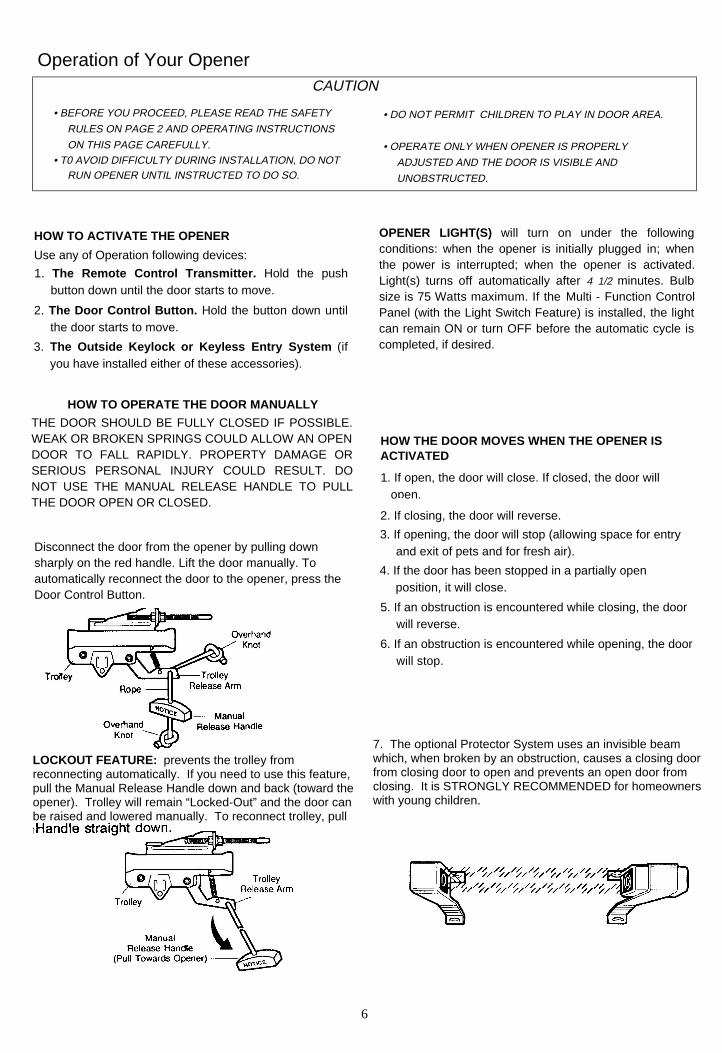
HOW TO OPERATE THE DOOR MANUALLY
THE DOOR SHOULD BE FULLY CLOSED IF POSSIBLE.WEAK OR BROKEN SPRINGS COULD ALLOW AN OPENDOOR TO FALL RAPIDLY. PROPERTY DAMAGE ORSERIOUS PERSONAL INJURY COULD RESULT. DONOT USE THE MANUAL RELEASE HANDLE TO PULLTHE DOOR OPEN OR CLOSED.
HOW THE DOOR MOVES WHEN THE OPENER ISACTIVATED
1. If open, the door will close. If closed, the door will open.
2. If closing, the door will reverse.
3. If opening, the door will stop (allowing space for entryand exit of pets and for fresh air).
4. If the door has been stopped in a partially openposition, it will close.
5. If an obstruction is encountered while closing, the doorwill reverse.
6. If an obstruction is encountered while opening, the doorwill stop.
Disconnect the door from the opener by pulling downsharply on the red handle. Lift the door manually. Toautomatically reconnect the door to the opener, press theDoor Control Button.
7. The optional Protector System uses an invisible beamwhich, when broken by an obstruction, causes a closing doorfrom closing door to open and prevents an open door fromclosing. It is STRONGLY RECOMMENDED for homeownerswith young children.
LOCKOUT FEATURE: prevents the trolley fromreconnecting automatically. If you need to use this feature,pull the Manual Release Handle down and back (toward theopener). Trolley will remain “Locked-Out” and the door canbe raised and lowered manually. To reconnect trolley, pullthe Manual Release Handle straight down.
CAUTION
6

CARE OF THE OPENER
When properly installed, opener will provide highperformance with a minimum of maintenance. The openerdoes not require additional lubrication.
Most complaints of unsatisfactory opener operation canbe traced to problems with the door itself. When operatedmanually, a properly balanced door will stay in any pointof travel while being supported entirely by its springs.
CHAIN TENSION ADJUSTMENT: After installation of theopener and adjustment of forces and limits, the chain mayappear loose. This is normal.
TO CHECK THE CHAIN TENSION: Disconnect the trolleyby pulling the red handle. If the chain returns to theposition described and illustrated in Step 3 page 9, DONOT make ANY further adjustments.
THE OPENER IS NOT INTENDED TO CORRECT ANY PROBLEMS THAT ARE CAUSED BY AN UNBALANCEDOR BINDING DOOR, BROKEN DOOR SPRINGS OR BYFAULTY DOOR HARDWARE.
REMOTE CONTROL TRANSMITTER: The portableremote control may be secured to a car sun visor with theclip provided. Additional remotes can be purchased at anytime for use in all vehicles using garage. Refer toAccessories on page 4.
Any new remotes must be set to the same code as theoriginal remote. Code setting procedures are described onpage 23.
LIMIT AND FORCE ADJUSTMENTS: These adjustments must be checked and properly set when opener is installed.Only a screwdriver is required. Pages 20 and 21 refer to thelimit and force adjustments. Follow the instructions carefully.
REMOTE CONTROL BATTERY: The 12 Volt batteryshould produce power for at least one year. As long asthere is adequate power, the transmitter battery test lightwill glow when the push button is pressed (and the openerwill operate). When the light becomes dim or does notcome on, replace the battery. If transmission rangelessens, check the battery test light.
TO CHANGE BATTERY: Slide the battery compartmentcover back. Discard the old battery and Position the newbattery as indicated on the case.
REPEAT THE SAFETY REVERSE TEST AFTER ANYADJUSTMENT. Weather conditions may cause someminor changes in the door operation, requiring somereadjustments, particularly during the first year ofoperation.
THE SAFETY REVERSE SYSTEM IS IMPORTANT (SEEGARAGE DOOR MUST REVERSE ON CONTACT WITHA 1-lNCH OBSTACLE PLACED ON THE FLOOR.FAILURE TO PROPERLY ADJUST OPENER MAYRESULT IN SERIOUS PERSONAL INJURY FROM ACLOSING GARAGE DOOR.
MAINTENANCE OF YOUR OPENER
TWICE A YEAR
MANUALLY OPERATED DOOR. If it is unbalanced orbinding, call for professional garage door service.CHECK TO BE SURE DOOR OPENS & CLOSES FULLY.Adjust Limits and/or Force if necessary.REPEAT SAFETY REVERSE TEST. Make any necessaryadjustments (See Page 22).
CHECK CHAIN TENSION. Adjust if necessary.
ONCE A YEAROIL DOOR ROLLERS, BEARINGS AND HINGES.
ONCE A MONTH
7

ASSEMBLY STEP 1Attach T-Rail To Opener
TO AVOID INSTALLATION DIFFICULTIES,DO NOT RUN OPENER UNTIL YOU AREINSTRUCTED TO DO SO.
USE ONLY THOSE SCREWS MOUNTED INTOP OF OPENER. FAILURE TO DO SOWILL CAUSE SERIOUS DAMAGE TO THEDOOR OPENER.
PROCEDURE: remove the two washered screws mountedin top of opener. Position T-Rail at a 45 degree angle toopener so one hole in T-rail and opener line up. Thread oneof the washered screws part way in.
CAUTION: USE ONLY THESE SCREWS! Use of any other screws will cause serious damage to door opener.
Align T-rail and styrofoam over opener sprocket. Cut tapefrom T-rail, chain and styrofoam.
REMOVE STYROFOAM. Proceed to Step 2.
ASSEMBLY STEP 2Attach Chain to Sprocket
PROCEDURE: Position chain over opener sprocket. Ifnecessary, loosen inner nut on trolley to obtain morechain slack. Insert second washered screw.
CAUTION: Use only the screw previously removed from opener
Tighten both screws securely through the T-rail intoopener as shown.
Insert back tab of sprocket cover in slot; then bend thecover forward and insert front tab in slot provided onmounting Plate.
8

ASSEMBLY STEP 3Tighten the Chain Assembly
CAUTION: Keep the chain from twisting as nuts are turned
PROCEDURE: Thread inner nut on the trolley in thedirection shown. Loosen outer nut, if necessary.
Tension is correct when the chain is approximately 1/2"above the base of the T-rail, midway between the pulleybracket and the opener.
To maintain proper tension, tighten outer nut as shown
Sprocket noise can result if chain Is either too looseor too tight.
CAUTION: Do not overtighten the chain. Refer toPage 7.
ASSEMBLY OF YOUR GARAGE DOOR OPENER IS NOW COMPLETE
BEFORE BEGINNING THE INSTALLATION OF YOUR GARAGE DOOR OPENER, BE SURE TOCOMPLY WITH ALL THE SAFETY RULES.
KEEP GARAGE DOOR BALANCED.STICKING OR BINDING DOORS MUST BEREPAIRED. THE GARAGE DOOR, DOORSPRINGS, CABLES, PULLEYS, BRACKETSAND THEIR HARDWARE ARE UNDEREXTREME TENSION AND CAN CAUSESERIOUS PERSONAL INJURY. DO NOTATTEMPT TO LOOSEN, MOVE ORADJUST THEM. CALL FOR GARAGEDOOR SERVICE
DO NOT WEAR WATCHES, RINGS ORLOOSE CLOTHING WHILE INSTALLINGOR SERVICING A GARAGE DOOROPENER.
IT IS RECOMMENDED THAT THE GARAGE DOOR OPENER BE INSTALLED 7 FEET OR MORE ABOVE THEFLOOR. WHERE SPACE PERMITS.
9

INSTALLATION STEP 1Position and Install Header BracketInstallation procedures vary according to garagedoor types. Follow the instructions which apply toyour door.
THE HEADER BRACKET MUST BE RIGIDLYFASTENED TO HEADER WALL. REINFORCEWALL WITH A 2x4 IF NECESSARY. FAILURE TOCOMPLY MAY RESULT IN IMPROPEROPERATION OF SAFETY REVERSE SYSTEM(SEE PAGE 22).
SECTIONAL DOOR & 1-PIECE DOOR WITH TRACK
1. Close door and mark the inside vertical centerline ofgarage door. Extend the line onto header wall abovedoor.
2. Open door to highest point of travel as shown. Drawan intersecting horizontal line on header wall 2" abovehigh point. This height will provide travel clearance fortop edge of door.
NOTE: When the headroom is not sufficient for 2"clearance, the bottom edge of bracket may be placedin line with the door's high point of travel.
3. Position bracket as shown (centered on verticalguideline with bottom edge of bracket on horizontalline).
Mark either top and bottom or left and right bracketholes. Drill 3/16" pilot holes and fasten bracket.

ONE-PIECE DOOR WITHOUT TRACKPLEASE READ AND COMPLY WITH THE WARNINGS ON PAGE 10. THEY APPLY TO THE INSTALLATION OFTHE HEADER BRACKET REGARDLESS OF DOOR TYPE.
1. Close door and mark inside vertical centerline of garage door. Extend line onto header wall above door.
2. Open door to highest point of travel as shown. Measure the distance from top of door to floor. Subtract actual height of door. Add 8" to remainder (See Example).
EXAMPLE
Distance from top of door (athighest point of travel) to floor................................................................................92”
Actual height of door ..............................................-88”
Remainder.................................................................4"
Add .........................................................................+8
Bracket height on header wall ...............................=12”
(Measure UP from top of CLOSED door.)
NOTE: If the total number of inches exceeds heightavailable In garage, use the maximum heightpossible. On finished ceilings, do not position thebracket closer than 1/2" from ceiling. POSITION AND FASTEN HEADER BRACKET AS
DESCRIBED AND SHOWN IN NO. 3 ON PAGE 10.
INSTALLATION STEP 2Attach the T-Rail to Header Bracket
PROCEDURE: Position opener on garage floor below header bracket. Use packing material as a protective base.
NOTE: To enable T-rail to clear sectional doorsprings, it may be necessary to lift opener onto atemporary support.
CAUTION: The opener must either be secured to asupport or held firmly In place by another person.
Raise T-rail until pulley and header brackets cometogether. Align bracket holes and join with clevis pin asshown. Insert ring fastener to secure.
11

INSTALLATION STEP 3Position the OpenerFollow instructions which apply to your doortype as illustrated.
TO PREVENT DAMAGE TO LIGHT WEIGHTDOORS AND/OR DOORS WITH WINDOWS, DONOT REST THE OPENER ON THE DOOR.
INSTALLATION-SECTIONAL DOOR & 1-PIECE DOOR WITH TRACK
NOTE: A 2 x4 is convenient for setting an ideal doorto T-rail distance. It is not necessary whereheadroom is insufficient.
PROCEDURE: Raise the opener onto a stepladder. Opengarage door. Place a 2x4 on the top section of door nearcenterline as shown. Rest T-rail on 2x4 as shown.
INSTALLATION - 1-PIECE DOOR WITHOUT TRACK
PROCEDURE: Measure the distance from floor to top ofdoor (in fully open position and parallel to the floor). Usinga stepladder as a support, raise opener to the samedistance from the floor (it will have a slight angle asshown).
The top of the door should be level with the top ofopener. For maximum efficiency, do not position openermore than 2 inches above this point.
12

INSTALLATION STEP 4Hang the Opener
THE OPENER MUST BE SECURELYFASTENED TO A STRUCTURAL SUPPORTOF THE GARAGE.
Three representative installations are shown. Yours may be different. Hanging brackets shouldbe angled (Fig.1) or crossed (Fig.2) to provide rigid support. On finished ceilings (Fig.3) , attach asturdy metal bracket (not supplied) to ceiling joists before installing opener.
PROCEDURE: Measure the distance from EACH side ofthe opener to the structural support.
Cut both pieces of the hanging bracket to requiredlengths. Flatten one end of each bracket and bend ortwist to fit the fastening angles. Do not bend at thebracket holes. Drill 3/16" pilot holes in structuralsupports. Attach flattened ends of brackets to thesupports with 5/16"x1-7/8" lag screws.
Lift opener and fasten to hanging bracket as shown.Check to make sure the T-rail is centered overdoor. REMOVE the 2x4.
Operate the door manually. If door hits the rail, raiseheader bracket.
Grease the top and underside of rail surface onwhich trolley slides. A tube of grease is supplied.
13

LOCATE DOOR CONTROL BUTTON (OR ANY ADDITIONAL PUSH BUTTONS) WHERE THE GARAGE DOOR IS VISIBLE.AWAY FROM DOOR AND DOOR HARDWARE AND OUT OF THE REACH OF CHILDREN.
SERIOUS PERSONAL INJURY FROM A MOVING GARAGE DOOR MAY RESULT FROM MISUSE OF OPENER.ALL OW CHILDREN TO OPERATE DOOR CONTROL BUTTON(S) or REMOTE CONTROL TRANSMITTER.
FASTEN THE CAUTION LABEL ON THE WALL NEAR DOOR CONTROL BUTTON AS A REMINDER OF SAFE OPERATINGPROCEDURES.
INSTALLATION STEP 5Install Lighted Door Control ButtonModels 1156,1155, 1146,1145,1140
OPERATION OF WIRING INSTRUCTIONS FOR ACCESSORIES LIGHTED DOOR CONTROL BUTTON
The Protector System Press to open or close door. Press again toREVERSE door during the CLOSING cycle or toSTOP door during OPENING cycle.
To white and black opener terminals
Outside Keylock
To red and white opener terminals
INSTALLING LIGHT: Install a 75 watt maximum lightbulb in socket as shown. The light will turn on andremain lit for 4-1/2 minutes when power is connected.After 4-1/2 minutes it will turn off.
If light bulb burns out prematurely due to vibration,replace with bulb specifically packaged for "GarageDoor Openers".
INSTALLING LENS (Models shown above except1140): Locate (and loosen approximately 1/8") the twoscrews near top of opener front panel. Position lensagainst panel with slotted tabs directly below screws.Slide lens up to seat tabs behind screws. Snap bottomtabs of lens into panel slots. Retighten top panel screwsto secure lens.
14

Install Multi-Function Door Control Panel
Models 1160 and 1150 ONLY
There are 4 screw terminals on the back of the Multi
Function Control. Connect bell wire by color; yellow
to yellow, white to white, red to red and black to black.
Install the Multi-Function Control on an inside garage wall asshown. Use anchors if installing into drywall a convenient place isalongside the service door.
LOCATE OUT OF THE REACH OF CHILDREN.
Run bell wire up the wall and across the ceiling to opener. Secure
with insulated staples.
Receiver terminals and antenna are Located on back panel of
opener. Position antenna wire as shown. Then connect the wire by
color to the red, white, black and yellow opener terminal screws.
OPERATION OF THE
MULTI-FUNCTION CONTROL PANEL
DOOR CONTROL PUSH BUTTON
Press to open or close door. Press again to REVERSE doorduring CLOSING cycle or to STOP door while OPENING.
LOCK SWITCH : Activate ONLY when door is closed. TheLOCK Switch is designed to prevent operation of door fromportable remote control transmitters. Door will OPEN from DoorControl Button, Key Switch and Keyless Entry Systems. Doorwill CLOSE if door control button is pressed and held until thedoor closes fully. If button is released before down travel iscompleted, door will reverse.
TO ACTIVATE: Press Lock Switch button. Indicator light willturn ON. TO TURN OFF: Press Lock Switch button again.Indicator light will turn OFF. Normal operation will
LIGHT SWITCHTO ACTIVATE: Press Light Switch button. Indicator light willturn ON. Opener light will turn on (or remain on if opener is stillin 41/2 minute automatic cycle). TO TURN OFF: Press LightSwitch button again. Opener light will turn OFF.
NOTE: To turn light OFF during 4-1/2 minute automaticcycle, press Light Switch button twice • to activate andthen to turn off Light Switch Feature. Light will turn OFFimmediately.
INSTALL THE LIGHTS
Install a 75 Watt maximum light bulb in each socket. Lights will turnON and remain lit for 4-1/2 minutes when power is connected. Thenthey will turn OFF. If bulbs burn out prematurely due tovibration, replace with "Garage Door Opener" bulbs.
INSTALL THE LENSES
Slide lens into guides as shown. Snap bottom tabs into lens slots.
For convenience, lenses may be installed after AdjustmentStep 3, Page 22.
WIRING INSTRUCTIONS FOR ACCESSORIES
The Protector SystemTo white and black opener terminals
Outdoor Key Switch:
To red and white opener terminals
15
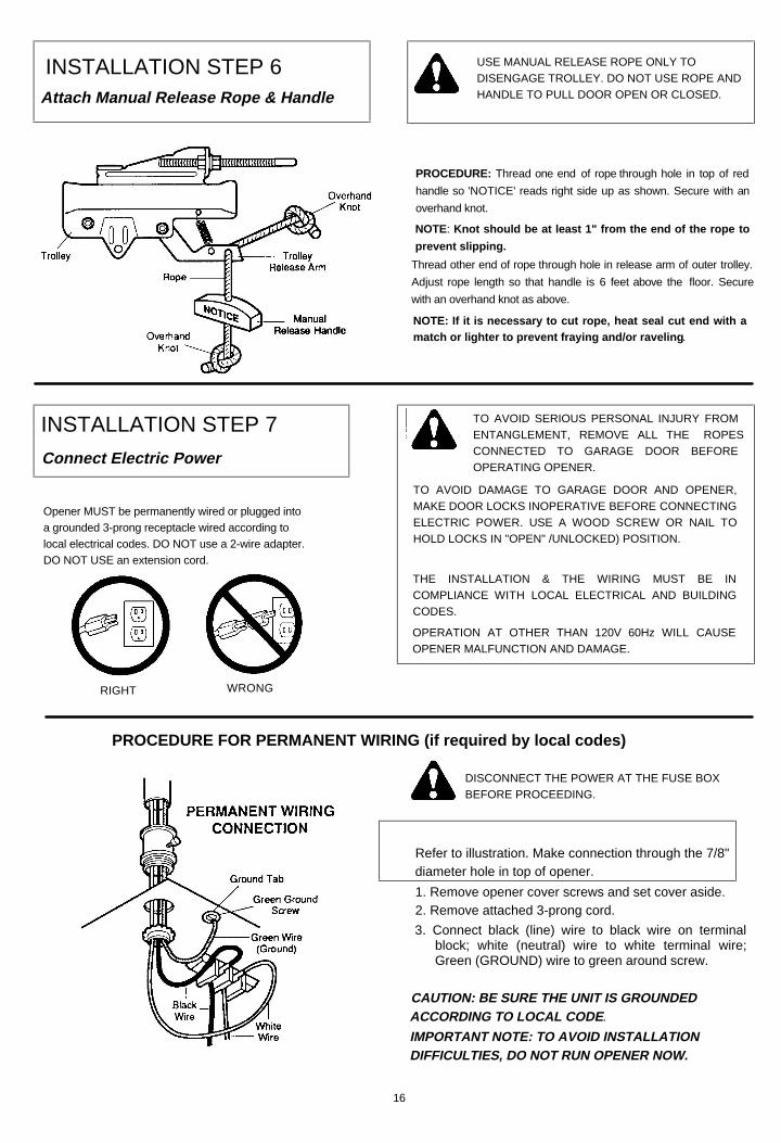
INSTALLATION STEP 6Attach Manual Release Rope & Handle
USE MANUAL RELEASE ROPE ONLY TODISENGAGE TROLLEY. DO NOT USE ROPE ANDHANDLE TO PULL DOOR OPEN OR CLOSED.
PROCEDURE: Thread one end of rope through hole in top of red
handle so 'NOTICE' reads right side up as shown. Secure with an
overhand knot.
NOTE: Knot should be at least 1" from the end of the rope to
prevent slipping.
Thread other end of rope through hole in release arm of outer trolley.
Adjust rope length so that handle is 6 feet above the floor. Secure
with an overhand knot as above.
NOTE: If it is necessary to cut rope, heat seal cut end with amatch or lighter to prevent fraying and/or raveling .
INSTALLATION STEP 7
Connect Electric Power
TO AVOID SERIOUS PERSONAL INJURY FROMENTANGLEMENT, REMOVE ALL THE ROPESCONNECTED TO GARAGE DOOR BEFOREOPERATING OPENER.
TO AVOID DAMAGE TO GARAGE DOOR AND OPENER,MAKE DOOR LOCKS INOPERATIVE BEFORE CONNECTINGELECTRIC POWER. USE A WOOD SCREW OR NAIL TOHOLD LOCKS IN "OPEN" /UNLOCKED) POSITION.
THE INSTALLATION & THE WIRING MUST BE INCOMPLIANCE WITH LOCAL ELECTRICAL AND BUILDINGCODES.
OPERATION AT OTHER THAN 120V 60Hz WILL CAUSEOPENER MALFUNCTION AND DAMAGE.
Opener MUST be permanently wired or plugged into a grounded 3-prong receptacle wired according to local electrical codes. DO NOT use a 2-wire adapter. DO NOT USE an extension cord.
RIGHT WRONG
PROCEDURE FOR PERMANENT WIRING (if required by local codes)
DISCONNECT THE POWER AT THE FUSE BOXBEFORE PROCEEDING.
Refer to illustration. Make connection through the 7/8" diameter hole in top of opener.
1. Remove opener cover screws and set cover aside.2. Remove attached 3-prong cord.
3. Connect black (line) wire to black wire on terminalblock; white (neutral) wire to white terminal wire;Green (GROUND) wire to green around screw.
CAUTION: BE SURE THE UNIT IS GROUNDEDACCORDING TO LOCAL CODE .
IMPORTANT NOTE: TO AVOID INSTALLATIONDIFFICULTIES, DO NOT RUN OPENER NOW.
16

INSTALLATION STEP 8Fasten Door Bracket and PlateFollow instructions which apply to your door typeas illustrated below.
TO PREVENT DAMAGE TO LIGHTWEIGHTAND METAL GARAGE DOORS (OR THOSEWITH GLASS PANELS),
ALWAYS REINFORCE THE INSIDE OF DOOR—BOTH VERTICALLY AND HORIZONTALLY—WITH2X4 BOARDS OR ANGLE IRON.
The horizontal brace should be at least six feet long. The vertical brace should cover height of top panel. The best solutionis to check with the garage door manufacturer for a door reinforcement kit to be used with an opener installation.
: :
Sectional Door Installation ProcedurePosition door bracket and plate assembly against door
within the following limits according to your requirements (and centered on vertical guideline— or to one toot left or right of center, if necessary):
A) Top edge of bracket 2" - 4" below top edge of door.
B) Directly below any structural support across top ofdoor.
Mark and drill 5/16" TOP and BOTTOM fastening holes.Secure bracket assembly as shown.
17
All One-Piece Door Installation Procedure
NOTE: The door bracket has left and right sidefastening holes. Assemble and Install the doorbracket and plate if your installation requires top andbottom fastening holes.
Center bracket (with or without plate as required) at thetop of the inside face of door as shown. Mark holes.
Drill 5/16" holes and fasten the door bracket withhardware supplied.

INSTALLATION STEP 9Connect Door Arm to TrolleyFollow instructions which apply to your doortype as illustrated.
SECTIONAL DOORS INSTALLATIONMake sure garage door is closed tight. Pull the manual release handle to disconnect the trolley. Manuallymove outer trolley back to the center of inner trolley as shown in Figures A, B and C.
FIG A: Fasten straight door arm section to outer trolleywith a clevis pin. Secure the connection with a ringfastener.
FIG B: Bring arm sections together. Find two pairs ofholes that line up and join sections. Select holes as farapart as possible to increase door arm rigidity.
Fasten curved section to the door bracket in the sameway.
FIG C: If holes in curved arm are ABOVE holes instraight arm, disconnect straight arm. Cut about 6"from the solid end. Reconnect to trolley with CUT ENDDOWN as shown.
Bring arm sections together. Find two pairs of holesthat line up and join with screws, lock washers andnuts.
Proceed to Step 1, page 20. Trolley will re-engage automatically when opener is operated.
18

ALL ONE-PIECE DOORS
ASSEMBLE DOOR ARM: Fasten straight and curveddoor arm sections together to their longest possiblelength. With door closed, connect straight door armsection to door bracket with a clevis pin. Secure with aring fastener.
Before connecting door arm to trolley, limits of travel must be adjusted on one-piece doors. Limitadjustment screws are located on left side panel as shown in illustration on Page 20. Follow proceduresbelow.
ADJUSTMENT PROCEDURES
OPEN DOOR ADJUSTMENT CLOSED DOOR ADJUSTMENT
Decrease UP limit. Turn UP limit adjustment screwcounterclockwise 4 complete turns.
Press door control button. Trolley will travel to full openposition.
Manually raise door arm to open position (parallel tofloor) and lift door arm to trolley. The arm should touchtrolley just in back of door arm connector hole asshown in solid line drawing. If arm does not extend farenough, adjust limit further. One full turn equals 2" ofdoor travel.
Decrease DOWN limit. Turn DOWN limit adjustmentscrew clockwise 8 complete turns.
Press door control button. Trolley will travel to fullclosed position.
Manually close door and lift door arm to trolley. Thearm should touch trolley just ahead of door armconnector hole as shown in dotted line drawing. If armis behind the connector hole, adjust limit further. Onefull turn equals 2" of door travel.
CONNECT DOOR ARM TO TROLLEY: With door closed, join curved arm to connector hole in trolley with remainingclevis pin. Secure with ring fastener. NOTE: It may be necessary to lift door slightly to make connection.
Run opener through a complete travel cycle. If door has a slight 'backward' slant in full open position, decrease UPlimits until door is parallel to floor.
19

THE FOLLOWING CHART OUTLINES ADJUSTMENT PROCEDURES. RUN THE OPENER THROUGH ACOMPLETE TRAVEL CYCLE AFTER EACH ADJUSTMENT .
NOTE: REPEATED OPERATION OF THE OPENER DURING ADJUSTMENT PROCEDURES MAY CAUSEMOTOR TO OVERHEAT AND SHUT OFF. SIMPLY WAIT 15 MINUTES AND TRY AGAIN.Read the chart carefully before proceeding to Step 2. Use a screwdriver to make limit adjustments.
LIMIT ADJUSTMENT CHART
IF DOOR DOES NOT OPEN COMPLETELYBUT OPENS AT LEAST FIVE FEET
IF ONE-PIECE DOOR DOES NOTCLOSE COMPLETELY
Increase UP travel. Turn the UP LIMIT adjustmentscrew clockwise. One turn equals 2" of travel.
If door does not open at least 5 feet: adjust UP(OPEN) FORCE as explained in Step 2.
IF DOOR DOES NOT CLOSE COMPLETELY
Increase DOWN travel. Turn down limit adjustmentscrew counterclockwise. One turn equals 2" of travel.
If the door still will not close completely, the headerbracket is positioned too high. See Step 1, page 10.
Increase DOWN travel. Turn down limit adjustmentscrew counterclockwise. One turn equals 2 inches oftravel.
IF OPENER REVERSES IN FULLYCLOSED POSITION.
Decrease DOWN travel. Turn down limit adjustmentscrew clockwise. One turn equals 2 inches of travel.
IF DOOR REVERSES WHEN CLOSING AND THEREIS NO INTERFERENCE TO TRAVEL CYCLE
Test door for binding: Pull manual release handle.Manually open and close door. If door is binding, call adoor serviceman. If door is not binding or unbalanced,adjust DOWN (CLOSE) FORCE. See Step 2.
LIMIT ADJUSTMENT settings regulate the points atwhich the door will stop when moving up or down.
NOTE: Door STOPS in the UP direction if anythinginterferes with door travel. Door REVERSES in theDOWN direction if anything interferes with the doortravel (including binding or unbalanced doors).
PROCEDURE: To operate the opener, press the DoorControl Button. Run the opener through a COMPLETETRAVEL CYCLE. No limit adjustments are necessarywhen the door opens and closes completely and doesn'treverse unintentionally when fully closed.
ADJUSTMENT STEP 1Adjust UP and DOWN Limits
20
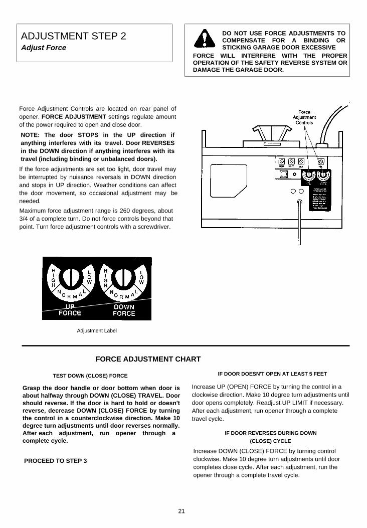
ADJUSTMENT STEP 2Adjust Force
DO NOT USE FORCE ADJUSTMENTS TOCOMPENSATE FOR A BINDING ORSTICKING GARAGE DOOR EXCESSIVE
FORCE WILL INTERFERE WITH THE PROPEROPERATION OF THE SAFETY REVERSE SYSTEM ORDAMAGE THE GARAGE DOOR.
Force Adjustment Controls are located on rear panel ofopener. FORCE ADJUSTMENT settings regulate amountof the power required to open and close door.
NOTE: The door STOPS in the UP direction ifanything interferes with its travel. Door REVERSESin the DOWN direction if anything interferes with itstravel (including binding or unbalanced doors).
If the force adjustments are set too light, door travel maybe interrupted by nuisance reversals in DOWN directionand stops in UP direction. Weather conditions can affectthe door movement, so occasional adjustment may beneeded.
Maximum force adjustment range is 260 degrees, about3/4 of a complete turn. Do not force controls beyond thatpoint. Turn force adjustment controls with a screwdriver.
Adjustment Label
FORCE ADJUSTMENT CHART
TEST DOWN (CLOSE) FORCE
Grasp the door handle or door bottom when door isabout halfway through DOWN (CLOSE) TRAVEL. Doorshould reverse. If the door is hard to hold or doesn'treverse, decrease DOWN (CLOSE) FORCE by turningthe control in a counterclockwise direction. Make 10degree turn adjustments until door reverses normally.After each adjustment, run opener through acomplete cycle.
PROCEED TO STEP 3
IF DOOR DOESN'T OPEN AT LEAST 5 FEET
Increase UP (OPEN) FORCE by turning the control in aclockwise direction. Make 10 degree turn adjustments untildoor opens completely. Readjust UP LIMIT if necessary.After each adjustment, run opener through a completetravel cycle.
IF DOOR REVERSES DURING DOWN
(CLOSE) CYCLE
Increase DOWN (CLOSE) FORCE by turning controlclockwise. Make 10 degree turn adjustments until doorcompletes close cycle. After each adjustment, run theopener through a complete travel cycle.
21

ADJUSTMENT STEP 3Test Safety Reverse System
THE SAFETY REVERSE SYSTEM TEST ISIMPORTANT. GARAGE DOOR MUST RE-VERSE ON CONTACT WITH A ONE-INCH
OBSTACLE PLACED ON THE FLOOR. FAILURE TOPROPERLY ADJUST OPENER MAY RESULT INSERIOUS PERSONAL INJURY FROM A CLOSINGGARAGE DOOR. REPEAT TEST ONCE A MONTH ANDADJUST AS NEEDED.PROCEDURE: Place-a one-inch obstacle on the floor
under the garage door. Operate door in DOWN direction.The door MUST reverse on the obstruction.
If the door STOPS on the obstruction, it is not travelingfar enough in the DOWN direction. Increase the DOWNlimit by turning DOWN limit adjustment screwcounterclockwise 1/4 turn. REPEAT TEST.
NOTE: Make sure limit adjustments do not force thedoor arm beyond a straight up and down position.See the illustration on Page 18/19.
When the door reverses on the one-inch obstacle,remove the obstruction and run the opener through acomplete travel cycle.
Door MUST NOT reverse in closed position. RepeatAdjustment Steps 1, 2 and 3 if necessary.
REPEAT ADJUSTMENT STEP 3 AFTER:
• EACH ADJUSTMENT OF DOOR ARM LENGTH, CLOSE
FORCE OR DOWN LIMIT.
• ANY REPAIR OR ADJUSTMENT OF GARAGE DOOR
(INCLUDING SPRINGS AND HARDWARE).
• ANY REPAIR OR BUCKLING OF THE GARAGE FLOOR R.
• ANY REPAIR OR ADJUSTMENT OF THE GARAGE DOOR
OPENER.
THE PROTECTOR SYSTEMInstallation of Optional Safety Feature
THE PROTECTOR SYSTEM PROVIDES AN ADDITIONALMEASURE OF SAFETY AGAINST A SMALL CHILD BEINGCAUGHT UNDER A GARAGE DOOR. It uses an invisible beamwhich, when broken by an obstruction, causes a closing door toopen and prevents an open door from closing. STRONGLYRECOMMENDED FOR HOMEOWNERS WITH YOUNGCHILDREN.
After opener has been installed and adjusted, THEPROTECTOR SYSTEM accessory can be installed.
Instructions are included with this optionaldevice.
22

Radio ControlsF.C.C. rules prohibit adjustments to or modification ofreceiver and/or remote control transmitter circuitryexcept for changing code setting and replacing remotecontrol transmitter battery. NO USER SERVICEABLEPARTS.
Manufactured under 1 or more of the following U.S. patents: RE29,525; 4,750,118; 4,8e8,930. Other Patents Pending.
ACTIVATE THE OPENER ONLY WHENDOOR IS IN FULL VIEW, FREE OFOBSTRUCTION AND PROPERLY
ADJUSTED. NO ONE SHOULD ENTER OR LEAVEGARAGE WHILE DOOR IS IN MOTION. DO NOTALLOW CHILDREN TO OPERATE REMOTES ORDOOR CONTROL BUTTONS. DO NOT ALLOWCHILDREN TO PLAY NEAR THE DOOR.
Your garage door opener receiver and remote control transmitter have been factory set to a matching code. If youwant to CHANGE your code or purchase additional remotes, follow the Instructions below. The code in any NEW remotecontrol must be set to match the code in the original remote control.
MATCH/CHANGE THE CODE IN REMOTE CONTROL(S)1. Slide battery compartment cover back to access code switches in your single function remote and any new remote control.
2. Place remotes side by side as shown and set switches in ALL remotes to matching positions (+, -, 0). Use a pen or screwdriver to slide the code switches.
NOTE: Instructions for matching the code switches in two-channel and multi-function remote controltransmitters are Included with those accessories.
MATCH/CHANGE THE CODE IN THE RECEIVER
GARAGE DOOR OPENERSWITH RECEIVER "SMART" CODE BUTTON
3. Press the RECEIVER Smart Button on the back panelof the opener as shown. The adjacent indicator lightwill turn ON.
CAUTION: Door will begin to move Immediately If anytransmitter has been activated.If this occurs, wait until the door has completed Its UPor DOWN cycle. Then begin again at Step 3.
4. STAND AWAY FROM THE DOOR and press theremote control transmitter push button. The indicatorlight will turn OFF and the door will move. Receiverand remote control(s) codes now match. The openerwill operate when either the door control button or theremote control transmitter push button is pressed.
NOTE: If the remote control transmitter push button isnot pressed within 30 seconds, the indicator light willturn OFF. In that case, begin again at steps 3.
23

Having a Problem? Review Pages 2 and 3 Before Proceeding
SITUATION PROBABLE CAUSE & SOLUTION
OPENER DOESN'T OPERATEFROM EITHER THE DOORCONTROL BUTTON OR REMOTECONTROL TRANSMITTER
1. Have you disengaged all door locks? Review Step 7, page 16.
2. Does the opener have electric power? Plug a lamp into the outlet. If it doesn't light, check fuse box or circuit breaker. (Some outlets are controlled by a wall switch.)
3. Repeated operation may have tripped the overload protector in the motor. Wait 15 minutes. Try again.
4. Is there a build-up of ice or snow under door? Door may be frozen to ground. Remove any obstruction.
5. Remove bell wire from opener terminals. Short red and white terminals by touching both terminals at same time with a piece of metal (screwdriver or coin). If opener runs, check for a faulty wire connection at door control button or a short under staples.
OPENER OPERATES FROMREMOTE CONTROL BUTNOT FROM DOOR CONTROLBUTTON
1. Is door control push button lit? If not, refer to No. 5 above and follow same procedure.
2. Are wiring connections correct? Review Step 5, page 14 or 15.
DOOR OPERATES FROMDOOR CONTROL PUSH BUTTONBUT NOT FROM THE REMOTECONTROL TRANSMITTER
1. Is the LOCK Switch ON? (Models 1160 and 1150) Turn it OFF.
2. Does the battery test light glow when remote control push button is pressed? If not, replace the battery.
3. If you have two remote controls and only one operates, review the code setting procedures on page 23. ALL remote controls must be set to same code.
REMOTE CONTROL TRANSMITTERHAS SHORT RANGE
1. Check battery test light. If the light is dim, change the battery.
2. Change the location of the remote control in the car.
3. A metal garage door or foil-backed insulation or metal siding will reduce the transmission range.
4. Check to be sure antenna on the back panel of opener extends fully downward.
THE GARAGE DOOR OPENSAND CLOSES BY ITSELF
1. Is there a neighbor with a garage door opener using the same frequency code? Change your code. Review page 23.
2. Check to be sure that the remote control push button is not stuck in the 'down' position.
3. Remove bell wire from opener terminals and operate from remote control only. If this solves the problem, the door control is faulty (replace), or there is a short or broken wire between door control button and opener.
DOOR DOESN'T OPENCOMPLETELY
1. Is something obstructing the door?
2. If door opens at least 5 feet, travel limits may need to be increased. One turn equals 2 inches of travel. See page 20. REPEAT SAFETY REVERSE TEST after the adjustment is complete.
3. If door has been working properly but now doesn't open all the way, increase the UP FORCE See page 21. REPEAT SAFETY REVERSE TEST after the adjustment is complete.
DOOR DOESN'T CLOSECOMPLETELY
1. Is something obstructing the door?
2. Review the Travel Limits Adjustment Chart on page 20. REPEAT SAFETY REVERSE TEST after any adjustment of door arm length, close force or down limit.
DOOR WON'T CLOSE 1. Check the Protector System (if you have installed this accessory). If the light is blinking, correct alignment.
24

Having a Problem? (continued)
SITUATION PROBABLE CAUSE & SOLUTION
DOOR REVERSES FORNO APPARENT REASON
1. Pull red manual release handle. Operate door manually. If it is unbalanced or binding, call a garage door serviceman to correct the problem.
2. Clear any ice or snow from garage floor area where garage door closes.
3. Review the Force Adjustment Chart on page 21. REPEAT SAFETY REVERSE TEST after adjustment is complete.
4. If door reverses in FULLY CLOSED position, decrease travel limits (Page 20). REPEAT SAFETY REVERSE TEST after the adjustment is complete. THE NEED FOR OCCASIONAL ADJUSTMENT OF THE FORCE AND LIMIT SETTINGS IS NORMAL. WEATHER CONDITIONS IN PARTICULAR CAN AFFECT DOOR TRAVEL.
5. Check the Protector System (if you have installed this accessory). If the light is blinking. correct alignment.
OPENER LIGHT(S) DOESN'T TURN ON1. Replace the light bulb (75 watts maximum). Use a "garage door opener bulb" if standard bulb burns out prematurely due to vibration. Vibration may be caused by loose end panel. Retighten screws.
DOESN'T TURN OFF
1. There may be a defective ground at ceiling or wall receptacle. UNIT MUST BE GROUNDED.
2. Is the Light Feature ON ? Turn it OFF.
OPENER STRAINS ORMAXIMUM FORCE IS NEEDEDTO OPERATE DOOR
1. Door may be out of balance or springs are broken. Close door and use manual release rope and handle to disconnect trolley. Open and close door manually. A properly balanced door will stay in any point of travel while being supported entirely by its springs. If it does not, call a garage door serviceman to correct the problem .
OPENER MOTOR HUMSBRIEFLY, THEN WON'T WORK
1. Garage door springs are broken. SEE ABOVE.
2. The trolley may be jammed into stop bolts. Pull or push on door while motor is humming to release jammed condition. Re-adjust door limits (page 20) to prevent over-travel.
REPEAT SAFETY REVERSE TEST after adjustment is complete.
3. If the problem occurs on first operation of the opener, door is locked. DISABLE DOOR LOCK. If chain was removed and reinstalled, motor may be out of phase. Remove chain; cycle motor to the down position. Observe drive sprocket. When it turns in clockwise direction and stops in down position, reinstall chain.
REPEAT SAFETY REVERSE TEST after adjustment is complete.
OPENER WON'T OPERATEDUE TO POWER FAILURE
1. Use manual release rope and handle to disconnect trolley. Door can be opened and closed manually. When the power is restored, press the door control button and trolley will automatically reconnect.2. The Outside Quick Release Lock accessory (for use on garages with no service door) disconnects the trolley from outside the garage in case of power failure.
CHAIN DROOPS OR SAGS 1. It is normal for chain to droop slightly in the closed door position. Use manual release rope and handle to disconnect trolley. If chain returns to normal height when the trolley is disengaged and door reverses on a one-inch obstruction, no adjustments are needed {see page 9).
OPENER NOISE IS DISTURBINGIN LIVING QUARTERS OF HOME
1. If operational noise is a problem because of proximity of the opener to the living quarters, Vibration Isolator Kit 41A3263 can be installed. This kit was designed to eliminate the 'sounding board effect' and is easy to install
25

RAIL ASSEMBLY PARTS LIST
INSTALLATION PARTS LIST
Lighted PushButton Assembly
41 A2756
Remote Control TransmitterCase, Cover & Screw Assembly
(circuit board not included)41 A3593
12V Battery10A14
2 Strand 4 StrandBell Wire Bell Wire217A238 217A241
Multi-FunctionControl Panel
41A3586
Remote ControlTransmitterVisor Clip29C128
Curved DoorArm Section
178B35
Door BracketPlate 12B380
Door Bracket12B374
Manual Release& Handle Assembly
41 A2828
Header Bracket PlusClevis and Fastener
41 A2829
Straight DoorArm Section 1178B34
26
1
2
3
4
5
6
7
8
9
11
10
12
15
13
14
16
17
18
19

Chassis Assembly Parts List
Repair Parts
27
KEY PARTNO. NO. DESCRIPTION
1 31C290 Sprocket cover2 41A2827 Gear and sprocket assy.
Complete with:Spring washerThrust washerRetaining ringBearing plateRoll pins (2)Drive gearWorm gearHelical gear w/retainerGrease
3 41A2817 Drive/worm gear kit w/ greaseRoll pins (2)
4 41B2991-1 Line cord5 143D100 End panel (Model 1145)
41A2916 End panel (Model 1160, 1150)6 175B88 Light socket7 108D36 Lens (Model 1145)
108D34 Lens (Models 1160, 1150)8 30B363 Capacitor - 1/2HP
30B387 Capacitor - 1/3HP9 12A373 Capacitor baracket
KEY PARTNO. NO. DESCRIPTION
10 41A3150 Terminal block w/screws11 41D3058 Universal replacement motor
/bracket assy. (Includesmotor, worm, bracket, bearingassy. and RPM sensor)
12 51R370 Cover (Specify model)13 41A2818 Helical gear & retainer w/grease14 41D3452 Limit switch assembly15 41C3005 RPM sensor assembly16 41C2726 Wire harness assy. w/plug17 41A2826 Shaft bearing kit18 41A2822 Interrupter cup assy.19 41A3627 Receiver logic board assy. (Model 1145)
41A3626 (Models 1160 and 1150)Complete with:Logic boardEnd panel w/all labels
20 41A3712 End panel w/all labels (Model 1145)41A3673 End panel w/all labels (1160 and 1150)
NOT SHOWN41A2825 Chassis assy. hardware kit (includes
screws not designated by a number inillustration)

LIFT-MASTER SERVICEIS ON CALL
HOW TO ORDERREPAIR PARTS
OUR LARGE SERVICE OrganizationSPANS THE UNITED STATES AND CANADA
Selling prices will be furnished on request or parts will beshipped at prevailing prices and you will be billed
INSTALLATION AND SERVICE INFORMATION IS ASNEAR AS YOUR TELEPHONE SIX DAYS A WEEK.SIMPLY DIAL OUR TOLL FREE NUMBER:
WHEN ORDERING REPAIR PARTS ALWAYS GIVE THEFOLLOWING INFORMATION:
• PART NUMBER
• PART NAME
• MODEL NUMBER1-800-654-4736
HOURS: 7:00 a.m. TO 3:30 p.m.(Mountain Std. Time)
MONDAY through SATURDAY
ADDRESS ORDERS TO:CHAMBERLAIN MFG., CANADA INC.
Unit 11 230 Bayview DriveBarrie Ont. Canada L4N 5E9
For professional installation parts and service contact yourlocal LIFT-MASTER/CHAMBERLAIN dealer. Look for him inthe Yellow Pages or call our Service number for a list ofdealers in your area.
SERVICE INFORMATION
TOLL FREE NUMBER:
1-800-654-4736
LIFTMASTER GARAGE DOOR OPENER ONE-YEAR LIMITED WARRANTY
The Chamberlain/Lift-Master warrants to the first retail purchaser of this product that it will be free from any defect in materials and/orworkmanship for a period of twelve full months from the date of purchase. The product must be used in complete accordance with Lift-Master's instructions for installation. or operation and care.
LIMITED WARRANTY ON MOTOR
Model 1160: The motor is warranteed to be free from any defect in materials and/or workmanship for a period of 60 full months (5 years)from the date of purchase.Models 1150 and 1145: The motor is warranteed to be free from any defect in materials and/or workmanship for a period of 36 full months(3 years) from the date of purchase.This warranty does not cover non-defect damage caused by unreasonable use (including abuse failure to provide reasonable andnecessary maintenance or any alterations to the product), labor charges for dismantling or reinstalling of a repaired or replaced unit orreplacement batteries.If during the warranty period the product appears as though it may be defective CALL OUR TOLL FREE SERVICE NUMBER BEFOREDISMANTLING IT (1-800-654-4736). If the product is then alleged to be defective please send it pre-paid and insured to our ServiceCenter to obtain warranty repair You will be advised of shipping instructions when you call the number listed above.Please be sure to include a brief description of the problem and a dated proof-of-purchase receipt with any product that is returned forwarranty repair.Product under warranty which upon receipt by Chamberlain/LiftMaster is determined to be defective in materials and/or workmanship will berepaired or replaced (Chamberlain's option) at no cost to you and returned pre-paid. Defective parts will be repaired or replaced with new orfactory rebuilt parts at Chamberlain's option.THE DURATION OF IMPLIED WARRANTIES OF MERCHANTABILITY AND FITNESS FOR A PARTICULAR PURPOSE IS LIMITEDTO THE DURATION OF THIS WRITTEN WARRANTY. SOME PROVINCES MAY NOT ALLOW LIMITATIONS ON HOW LONG ANIMPLIED WARRANTY LASTS SO THE ABOVE LIMITATION MAY NOT APPLY TO YOU.All claims for consequential or incidental damages for breach of this warranty are excluded and in no event shall manufacturer's liability forbreach of warranty negligence strict liability or breach of contract exceed the cost of the product covered herein but the purchaser is entitledto the remedies expressly provided in this policy. Some provinces do not allow the exclusion or limitation of incidental or consequentialdamages so the above limitation or exclusion may not apply to you.
No representative or person is authorized to assume for us any other liability in connection with the sale of this product. This warranty givesyou specific legal rights and you may also have other rights which may vary from province to province.
1990, Chamberlain Mfg. CanadaInc. All rights reserved
114A1297 Printed in Mexico