Embed Size (px)
DESCRIPTION
GDE Baseline Workshop #2 - Overview. Motivation and Background behind the proposals to revise the RDR baseline. Marc Ross , (Fermilab) Nick Walker, (DESY) and Akira Yamamoto (KEK). Workshop Program – BAW-2. Reduced Beam Parameter set n_b reduced 2x from 2625 to 1312 (‘low beam power’) - PowerPoint PPT Presentation
Citation preview

GDE Baseline Workshop #2 - Overview
Marc Ross, (Fermilab)
Nick Walker, (DESY)
and Akira Yamamoto (KEK)
BAW-2, SLAC, 18 January 2011 Marc Ross, Fermilab 1
Motivation and Background behind the proposals to revise the RDR baseline

Workshop Program – BAW-2
1. Reduced Beam Parameter set– n_b reduced 2x from 2625 to 1312 (‘low beam power’)
2. Positron Source Relocation– Source moved from the 2/3 point to the end of the linac
Objectives of the Workshop:• Assess technical implication• Including impact across system interfaces• Discuss with community • Prepare recommendations for ‘Top-Level’ Change
Control (TLCC)
BAW-2, SLAC, 18 January 2011 Marc Ross, Fermilab 2

Workshop Scheme:
• Open meeting• Presenters:
– GDE PMs (Chair) – GDE ADI team / TAG leaders – Physics/Detector Representatives
• Registered: 68– (22 Asia, 17 EU, 29 Americas)
• Workshop Dinner Wednesday• Thank you very much to SLAC for hosting
BAW-2, SLAC, 18 January 2011 Marc Ross, Fermilab 3

Overview
• Changing the ILC Baseline – TLCC / BAW Process
• Background: Motivation for Cost Containment– TDR will have updated cost estimates for SRF and
CFS
1. Reduced Beam Parameter Set
2. Positron Source Relocation – (Ewan Paterson, Thursday Jan 20)
• Summary
BAW-2, SLAC, 18 January 2011 Marc Ross, Fermilab 4

Topics
• Reduced Beam Parameter set– Day 1 (18 Jan): Accelerator and Technical– Day 2: Cost and Impact (Physics Performance)
• Positron Source Relocation– Day 3: Accelerator and Technical– Day 4: Cost and Wrap-up
• Independent Proposals… with a few common issues
BAW-2, SLAC, 18 January 2011 Marc Ross, Fermilab 5
SB2009 ThemesHLRF:Klystron Cluster – KCSDistributed RF - DRFS
BAW-2, SLAC, 18 January 2011 Marc Ross, Fermilab 6

TLCC Themes
BAW-2, SLAC, 18 January 2011 Marc Ross, Fermilab 7

TLCC Themes
Potential Physics Impact
BAW-2, SLAC, 18 January 2011 Marc Ross, Fermilab 8
HLRF System Impact

BAW-1: Recommendations
1. Gradient– Remain at 31.5 MV/m average accelerating gradient
• → fixed tunnel length
– Additional RF power to accommodate a spread in gradient (±20%)• → higher mass-production yield expected cost effective⇒
– TDP2 R&D remains ≥35 MV/m low-power vertical test (90% yield)• infers <G> ~38 MV/m VT (additional margin)
2. Single-Tunnel (Main Linac)– Go forward with SB2009 proposal– Both KCS and DRFS R&D have significantly progressed– Inclusion of RDR HLRF Technology option as back-up
solution
9
Approx. 58 participants
physics & detector reps.
http://ilcagenda.linearcollider.org/conferenceTimeTable.py?confId=4593
Now formally accepted as baseline!
BAW-2, SLAC, 18 January 2011 Marc Ross, Fermilab

BAW-2 Themes• Reduction of # bunches (2625 → 1312)
– Reduced beam power → reduced RF– Smaller damping rings (6.4 km → 3.2 km)– Regain luminosity via stronger focusing at IP
• Re-location of e+ source to end of Main Linac– Better integration (central campus) – higher overhead (at
500 GeV running) reduced risk⇒– Issues of running for Ecm < 300 GeV
Parameter Table link

BAW-2 Themes• Reduction of # bunches (2625 → 1312)
– Reduced beam power → reduced RF– Smaller damping rings (6.4 km → 3.2 km)– Regain luminosity via strong focusing at IP
• Re-location of e+ source to end on Main Linac– Better integration (central campus) – higher overhead (at
500 GeV running) reduced risk⇒– Issues of running for Ecm < 300 GeV
10 Hz alternate pulse mode

TLCC Process
Issue Identification• Planning• Identify further studies• Canvas input from stakeholders• …
Baseline Assessment Workshops• Face to face meetings• Open to all stakeholders• Plenary
Formal Director Approval• Change evaluation panel• Chaired by Director
keywords: open, transparent
Process covered by B. Barish
BAW-2, SLAC, 18 January 2011 Marc Ross, Fermilab 12
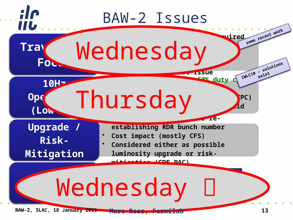
BAW-2 Issues• More detailed simulations required• Stability issues → impact on feedback and
tolerances• considered higher-risk option• Inclusion not a cost issue
Travelling Focus
• Positron damping ring 50% duty cycle• RF solution (this workshop)• Understanding cost impact (1.9% TPC)• Other emerging options (high-field undulator)
10Hz Operation (Low Ecm)
• Understand scenarios for re-establishing RDR bunch number
• Cost impact (mostly CFS)• Considered either as possible luminosity
upgrade or risk-mitigation (GDE PAC)
Upgrade / Risk-Mitigation
Physics impactWorking with Physics & Detector groups as part of the TLCC process
some recent work
IWLC10 – solutions existWednesday
Thursday
Wednesday BAW-2, SLAC, 18 January 2011 Marc Ross, Fermilab 13

BAW-2 Agenda – ‘Low Power’
• Overview• Technical:
– HLRF – Chris N. and Shigeki– Cryo / CFS – Tom and Vic
• Accelerator– DR – Susanna and Mark– BDS - Andrei– Other AS – Axel and Nikolay
• Cost – Peter• Physics Impact • Summary and Proposal development – Nick
BAW-2, SLAC, 18 January 2011 Marc Ross, Fermilab 14

Physics Impact: Agenda
• Wednesday Afternoon (19.01)– Organized with help from Jim Brau
BAW-2, SLAC, 18 January 2011 Marc Ross, Fermilab 15

PAC Review* – 11.2010
PAC Comments on SCRF: (color added)• The PAC is very pleased to note that the GDE’s approach to
cavity production in the ILC construction phase intends to follow the successful example of the LHC in the industrialization of complex superconducting components, rather than that of the much smaller-scale XFEL project.
• The PAC is very impressed by the recent progress on SCRF cavity gradients; 9 out of 10 cavities from one manufacturer meeting the nominal ILC gradient requirement is an outstanding achievement.
• There is a need to pay attention to the issue of field emission in the SCRF cavities.
* Project Advisory Committee – reports to ILCSC
BAW-2, SLAC, 18 January 2011 Marc Ross, Fermilab 16

PAC Review – 11.2010 (2)
PAC Comments on Baseline Assessment: (color added)• The PAC endorses the methodology for GDE design
change control which is now in place, and which appears to be working well. The Committee also notes positively the membership of a detector physicist on the GDE Change Evaluation Panel.
• The PAC sees significant progress in addressing the issues raised by the SB2009 proposals, including progress towards resolution of several hardware questions following from the proposals. The Committee is gratified to observe the greatly improved collaboration with the detector community in SB2009 discussions.
BAW-2, SLAC, 18 January 2011 Marc Ross, Fermilab 17

• Changing the ILC Baseline – TLCC• Background: Motivation for Cost
Containment– TDR will have updated cost estimates for
SRF and CFS• Reduced Beam Parameter Set• Positron Source Relocation
– (Ewan Paterson, Thursday Jan 20)
• Summary
BAW-2, SLAC, 18 January 2011 Marc Ross, Fermilab 18
Overview

Costing effort: 2011-2012
• TDR will reflect SCRF and CFS progress– (beyond RDR 2007)– Technical advancement (esp. R & D)– Project strategy (design, industrialization, siting)– AND COST
• Balance performance scope and accelerator system design against these cost drivers
• Motivation for Cost – Containment– Development of SCRF 2007– Siting 2010
BAW-2, SLAC, 18 January 2011 Marc Ross, Fermilab 19

ILC10 Opening Joint Plenary - PM
RDR 2012 Technical Design
• Strong Basis for SCRF technology in each ILC region– Cavity fabrication and test: Each region– Global Cryomodule: KEK +
• Large scale Costed technology demonstration– EU XFEL (5% of ILC); first beam mid-2014
• Siting: adaptation to best suit potential hosts• Beam – based studies and demonstrations
– High power SCRF linac operation: DESY +– Electron-cloud beam dynamics: Cornell +– Beam delivery technology: KEK +
20BAW-2, SLAC, 18 January 2011 Marc Ross, Fermilab
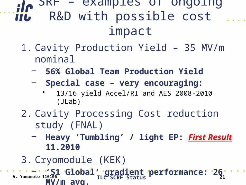
SRF – examples of ongoing R&D with possible cost impact
1. Cavity Production Yield – 35 MV/m nominal– 56% Global Team Production Yield– Special case – very encouraging:
• 13/16 yield Accel/RI and AES 2008-2010 (JLab)
2. Cavity Processing Cost reduction study (FNAL)– Heavy ‘Tumbling’ / light EP: First Result 11.2010
3. Cryomodule (KEK)– ‘S1 Global’ gradient performance: 26 MV/m avg.
4. EU-XFEL (DESY)– 584 cavities ordered: complete 02.14 (2 x 25 M €)
A. Yamamoto 110106 ILC SCRF Status 21

Rongli Geng ILC Visit, 1/6-7, 2011, Jefferson Lab 22
Hpk 160-180 mT
Cavity Gradient R & D – Rongli Geng, Jefferson Lab

Rongli Geng ILC Visit, 1/6-7, 2011, Jefferson Lab 23
Cavity Gradient R & D – Rongli Geng, Jefferson Lab

Rongli Geng ILC Visit, 1/6-7, 2011, Jefferson Lab 24
55
A possible Gradient Yield Curve by 2015?Cavity Gradient R & D – Rongli Geng, Jefferson Lab

Tumbled Cavity (CBP) – re-Process & Test
25
Cavity Process R & D – Cooley / Cooper FNAL

S1-G: 7 Cavity-String Operation
Average field gradient achieved:
VT: 30 MV/m S1G-Single: 27 MV/m, 7-string 26 MV/m
26BAW-2, SLAC, 18 January 2011 Marc Ross, Fermilab
Cryomodule Assembly and Test – Kako, KEK

BAW-2, SLAC, 18 January 2011 Marc Ross, Fermilab 27
XFEL Cavity Procurement – Eckhard Elsen, DESY

Siting Process - CFS
• RDR: Deep-Rock sites with similar characteristics
• TDP:– Specific sites with geotechnical /
environmental constraints– (e.g. Two Japanese mountainous region sites)– Preparation for Site Selection
• Adaptation of technical criteria to facilitate siting process• Supported through R & D and Design work
A. Yamamoto 110106 ILC SCRF Status 29

Siting – Site Selection Process (IL-2)
Step-D: Process of narrowing-down the site candidates through an inter- governmental level consultation, including discussions on general political aspects
Pre-ILC Lab. ILC Lab.
- - - 2011 - - - - - - - -| - - - - - 2012 - - - - - | - - - - - - 2013 - - - - -
Step-D
30
Site-Selection Procedurestarts soon.
Atsuto Suzuki, KEK DG (BAW -1)

ILC in a Mountainous Region
31BAW-2, SLAC, 18 January 2011 Marc Ross, Fermilab 31
How to make the ILC design suitable for a variety of sites?
There is an encouraging possibility Japan will bid to host the ILC…
It is up to us to interpret RDR CFS criteria to clearly show that such a site would work and would be cost-effective…

Costing Effort: Summary
• SCRF:– Interaction with Industries in each region – 2011– XFEL Contract exposure 01.2011 (after 6 months)– Impact of allowing Gradient Spread - 2010
• CFS + HLRF:– Engineering and Design Contracts - 2011– Mountain site and DRFS preliminary cost – mid
2011
BAW-2, SLAC, 18 January 2011 Marc Ross, Fermilab 32

Cost Containment Estimated Impact:
• RDR ML Technical Cost:– 2/3 cold SCRF– 1/3 Modulator/infrastructure, Klystron, Power
Distribution• ½ Modulator• ¼ Klystron• ¼ PDS
• Half-Power ~ 16% ML technical reduction• Could offset ~25% cold SCRF ‘increase’• TDR cost breakdown will differ 2011• (see talks by Peter Garbincius, Wed/Fri)
BAW-2, SLAC, 18 January 2011 Marc Ross, Fermilab 33
• Changing the ILC Baseline – TLCC• Background: Motivation for Cost
Containment– TDR will have updated cost estimates for SRF and
CFS
• Reduced Beam Parameter Set– HLRF, DR, other Accel. Sys. and CFS/Cryo
• Positron Source Relocation – (Ewan Paterson, Thursday Jan 20)
• Summary
BAW-2, SLAC, 18 January 2011 Marc Ross, Fermilab 34
Overview
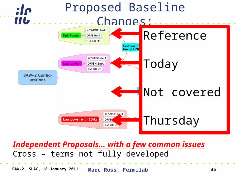
Proposed Baseline Changes:
BAW-2, SLAC, 18 January 2011 Marc Ross, Fermilab 35
Independent Proposals… with a few common issuesCross – terms not fully developed
Reference
Today
Not covered
Thursday

1. A reduction of the number of bunches per pulse (nb) by a factor of two from 2625 to 1312.
2. A corresponding reduction in Main Linac beam current, and therefore beam power, and an associated reduction in the number of klystrons, modulators and power supplies (primary cost saving).
Key conventional facilities support for the full RDR RF power will be installed upfront during construction, in support of future possible upgrade to higher bunch numbers (risk mitigation).
3. A corresponding reduction in the circumference of the damping rings from 6476 m to 3238 m (i.e. 50%), while maintaining the DR current approximately constant. This includes the associated reduction in DR RF power by approximately 50% (primary cost saving).
4. An increase in the DR tunnel diameter to accommodate the possibility of installing a third damping ring (second positron damping ring) at some later date, if required (risk mitigation).
5. Adoption of stronger focusing at the interaction point (enhanced beam-beam) – including the possibility of travelling focus – to provide the required luminosity (maintaining performance at higher risk).
Reduced beam parameter set - Proposal

Positron Source Relocation - Proposal
• Ewan Paterson – Thursday– some overlap Technical presentations
1) A relocation of the positron source systems from the nominal 150 GeV point of the electron Main Linac to the exit of the electron Main Linac (≤250 GeV depending on physics scenario), integrated into the beginning of the Beam Delivery System.
2) The new baseline proposal includes a description of a possible low energy operational scheme. The scheme (10 Hz running alternate pulse) is consistent with the RDR: “Physics runs are possible for every energy above √𝑠 = 200 GeV”. The positron yield is ≥1.5 over this energy range and enables operation with the RDR parameters or the ‘Reduced Beam Parameter Set.’

Reduced Bunch Number - Introduction
As outlined in the SB2009 report. • reduce cost with fewer ML HLRF stations and a half the
damping ring circumference. • Luminosity performance is restored either in-part or
completely through stronger interaction region focusing, including possible use of the ‘travelling focus’ scheme.
• key addition to the original SB2009 proposal is the explicit inclusion of support for increasing the number of bunches at a later
• Include ‘gradient spread’ and KCS / DRFS (‘single tunnel HLRF’)
• (Key high-power systems, such as beam dumps, would not be reduced and would retain nominal RDR performance)
BAW-2, SLAC, 18 January 2011 Marc Ross, Fermilab 38

Low Power Parameters
Parameter unit RDR (nom.) TLCC
Ecm GeV 500 500
Rep. rate Hz 5 5
Qbunch nC 3.2 3.2
Bunches/pulse 2625 1312
LINAC RF parameters:
RF pulse length ms 1.6 KCS: 1.6DRFS: 2.2
Beam current mA 9 KCS: 6DRFS: 4.5
Damping Ring:
Circumference m 6476 3238
Avg. Current mA 388 390
Damping time ms 21 24
RF power MW 3.97 1.76
• Focus on 500 GeV centre-of-mass– Low Ecm cf
‘Positron Source Relocation’
• Different parameters for DRFS and KCS
• 2x3.2km DR with reduced bunch number (@5Hz)
BAW-2, SLAC, 18 January 2011 Marc Ross, Fermilab 39

Since RDR / SB2009:
• Gradient Spread (BAW 1)– RDR design: each cavity set to 31.5 MV/m– TDR baseline: 31.5 avg +/- 20%– Penalty: Increased HLRF overhead (10 - 15%)– (offset by decreased cavity cost; model dependent)
• Single Tunnel (BAW 1)– Facilitate siting through flexible HLRF technology– Penalty: different criteria for CFS / Cryo design
• Consider restoration of full beam parameters– Penalty: Identify and reserve space / support
equipment needs
BAW-2, SLAC, 18 January 2011 Marc Ross, Fermilab 40

Gradient Spread: HLRF overhead
BAW-2, SLAC, 18 January 2011 Marc Ross, Fermilab 41
RF Power Installed capacity #'d pg 81 slide 44 slide 9
RDR 2.6-2 RDR 2.6-2 KCS KCS DRFSNo gradient spreadw/ gradient spreadequal CTO power tailored CTO power
beam current 9 9 9 9 9 mAgradient 31.5 31.5 31.5 31.5 31.5 MV/mpower to beam 294.3 294.3 294.3 294.3 294.3 KWcavity spread - limited tuning ability 1 1.06 1.06 1.06 1cavity spread statistics - excess for high power combination 1.00 1.00 1.06 1.00 1.21cavities/RF unit 26 26 26 26 2local dist loss 0.93 0.93 0.95 0.95 0.975peak power / RF unit 8227 8721 9058 8529 728 KWRF unit assemblies 1 1 28 28 1Additional losses 1 1 0.86 0.86 1total power/ unit 8,227 8,721 294,742 277,535 728 KWControls overhead 1.16 1.14 1.07 1.07 1.09required power 9,543 9,941 315,374 296,963 794 KWnominal available klystron power 10000 10000 10000 10000 800 KWnumber of klystrons 1 1 32 30 1 additional overhead (in fractional klystrons) 4.6% 0.6% 46.3% 30.4% 0.8%
9 mA – Full beam parameters

KCS HLRF Overhead SummaryThere are multiple reasons for the increase in required klystrons per 28 rf units:
klystrons:
28 equivalent to the RDR requirement, 1 per rf unit.
+2 7% more for long range distribution for eliminating service tunnel.
+2 for redundancy (allowing one failure). In the RDR, such failures had to be covered by including additional rf units.
+2 to recover enough for 5(7)% LLRF overhead after a 12.5% hit due to cavity gradient spread (flat gradient w/ common timing andfeed statistics). Most of this hit would exist in the RDR scheme.
34
NOTE: The preceding calculations could well be off by ~2-3 percent, depending on actual cavity distribution and error margins in loss estimates.
Nantista, SLAC
9 mA – Full beam parameters

HLRF – two technical options
• Both options subject to R & D; – both to be included in TDR if resp. R & D successful
• Different optimum bunch parameters– Both have reduced plug–to-beam efficiency
BAW-2, SLAC, 18 January 2011 Marc Ross, Fermilab 43
Key Main Linac HLRF parameters at 500 GeV centre-of-mass (approximate numbers)
Parameter unit RDR (nominal) KCS DRFS Beam current mA 9 6 4.5 Bunch spacing ns 369 535 738 Beam pulse length sμ 969 702 969 RF fill time sμ 595 862 1190 RF pulse sμ 1564 1564 2159

SRF Linac Matched Condition – • Minimal CW losses + matched condition: all power to the
beam• lower current --- less power needed during pulse• less power available --- longer filling time (before pulse) –
could be offset by additional peak power• explore trade-off between peak power / average power• mismatch may actually help reduce plug power needs
BAW-2, SLAC, 18 January 2011 Marc Ross, Fermilab 44
half beam current
full beam current
Cavity Voltagehalf currentfull current
In the matched condition, the power in and coupling exactly compensate power extracted by a single bunch – no reflected power during beam pulse
738 ns
KCS – optimum bunch parameters
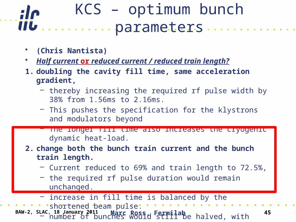
• (Chris Nantista)• Half current or reduced current / reduced train length?
1. doubling the cavity fill time, same acceleration gradient,– thereby increasing the required rf pulse width by 38% from 1.56ms
to 2.16ms. – This pushes the specification for the klystrons and modulators
beyond – The longer fill time also increases the cryogenic dynamic heat-load.
2. change both the bunch train current and the bunch train length. – Current reduced to 69% and train length to 72.5%, – the required rf pulse duration would remain unchanged. – increase in fill time is balanced by the shortened beam pulse. – number of bunches would still be halved, with their spacing
increased by a factor of 1.45, rather than doubled.
BAW-2, SLAC, 18 January 2011 Marc Ross, Fermilab 45

BAW-2, SLAC, 18 January 2011 Marc Ross, Fermilab 46
KCS Surface Buildings
Presentation Scope of DRFS in BAW-2
47Jan. 7 2011
DRFS Scheme
(Shigeki Fukuda)• Consider upgrade process for HLRF
hardware in the tunnel – It is necessary to develop a model ILC
Construction/Operation Schedule
• Consistent model and scheme is invaluable for all over the periods of ILC schedule.
• Layout and cost are depends on this consistent model.
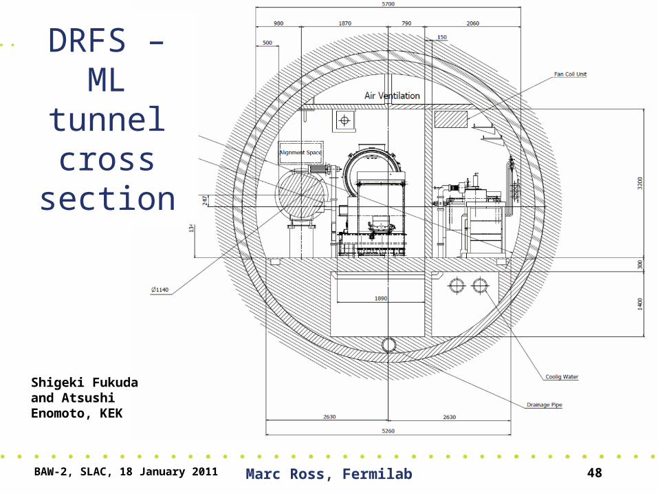
DRFS – ML tunnel
cross section
BAW-2, SLAC, 18 January 2011 Marc Ross, Fermilab 48
Shigeki Fukuda and Atsushi Enomoto, KEK

Presentation Scope of DRFS in BAW-2
49Jan. 7 2011
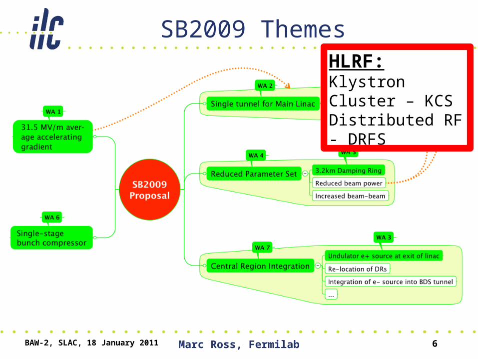
ILC Construction/Operation Scheme and DRFS
Revised schedule scheme and base of the presentation for BAW-2
Energy(GeV) Rep(Hz) Energy(GeV) Rep(Hz)
0 ? Operation Low Energy Option 250 4.5 125 5 125 5 0.250-0 Upgrade
Low Energy Option 150 510 Hz 125 5 125 5
0-2 Operation 300 GeV Operation 300 4.5 150 5 150 5 0.30-3…… ↓ ↓ ↓ ↓ ↓ ↓ ↓ ↓1-0 Upgarde
Low Power OptionSB2009
2-0 Upgrade
250 5
250 5
Rel. Beam
PowerStep Status
Electron PositronMode
Center of Mass
Energy(GeV)
Current
(mA)
4000 RF Sources are installed
2-1 Operation RDR 500 9 5 1250
<0.5
Revised from 10Hz Operation Mode to SB2009
1-1 Operation 500 4.5 5 0.5250
0-1 Operation 250 4.5
Shigeki Fukuda, KEK
Presentation Scope of DRFS in BAW-2
50Jan. 7 2011
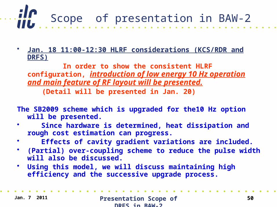
Scope of presentation in BAW-2
• Jan. 18 11:00-12:30 HLRF considerations (KCS/RDR and DRFS)
In order to show the consistent HLRF configuration, introduction of low energy 10 Hz operation and main feature of RF layout will be presented.
(Detail will be presented in Jan. 20) The SB2009 scheme which is upgraded for the10 Hz option will be
presented. • Since hardware is determined, heat dissipation and rough
cost estimation can progress. • Effects of cavity gradient variations are included.• (Partial) over-coupling scheme to reduce the pulse width will also be
discussed. • Using this model, we will discuss maintaining high efficiency and the
successive upgrade process.

Damping Ring
(Susanna, Mark and Junji)
Reduce Circumference 2x:• Design of 3.2 km DR • (including component counts, cost savings and
upgrade path configurations with 2 and 3 rings)
Evaluate e+ instability thresholds for • increasing the number of bunches at a later stage• Electron cloud issues at 1312 and 2625 bunches
• DR cost ~ 10% RDR (1/3 CFS)– Technical cost does not scale some component counts are
fixed
BAW-2, SLAC, 18 January 2011 Marc Ross, Fermilab 51

BDS• 50% reduction Pbeam ×2 ⇒ L recovery via enhanced
beam-beam (BDS)– stronger focusing (tighter tolerances, see below)– higher disruption / beamstrahlung etc.– travelling focus– Collimation depth issues– Modular FD concept (for low Ecm running)
• Cost neutral– travelling focus hardware has negligible cost
• Concern with operational aspects and tighter tolerances– Collision (luminosity) stability– more demands on beam-beam feedback– Emittance preservation in RTML, ML and BDS– Overall tuning strategies and integrated luminosity performanceBAW-2, SLAC, 18 January 2011 Marc Ross, Fermilab 52
A higher risk scenario?
Note reduced average beam power reduces risk in many subsystems
Andrei

CFS – KCS Power Load
Diagram Courtesy E. HuedemInformation Courtesy of C. Nantista

54
CFS – KCS/DRFS Power Summary
• Changing the ILC Baseline – TLCC• Cost Containment
– TDR will have updated cost estimates for SRF and CFS
• Reduced Beam Parameter Set• Positron Source Relocation
– (Ewan Paterson, Thursday Jan 20)
• Summary
BAW-2, SLAC, 18 January 2011 Marc Ross, Fermilab 55
Overview

Bunch number “restoration”
• Scenarios for increasing the bunch number 1300→2600– At some later date, after initial construction.
• Damping Ring:– Additional 3.2km ring for positrons → no parameter changes– 2625 bunches in single (existing) electron ring
• 780 mA avg. current• 4.84 MW power
– Tunnel/alcoves spec’d for 3 stacked rings.
• HLRF– Add klystrons/modulators/power supplies– Scenarios for CFS support
• what must we invest in up-front to support this
• Complete studies left for TDP-2– but qualitatively, scenarios need to be discussed at BAW-2
BAW-2, SLAC, 18 January 2011 Marc Ross, Fermilab 56

+ / - Reduced Beam Parameters
• Pro’s:– Largest single-item cost impact– Minimum technical risk for the change itself– Manageable restoration path
• KCS, DRFS, DR
• Con’s:– Luminosity reduction to be compensated in BDS– Reduced ML efficiency– Significant cost penalty to maintain restoration
path• DR, CFS
BAW-2, SLAC, 18 January 2011 Marc Ross, Fermilab 57

Summary
• HLRF system / DR cost reduction intended to offset possible SRF / CFS cost increase– Second only to cavity R & D
• R & D on HLRF – KCS, DRFS and System test (FLASH)– KCS components under test at SLAC– DRFS now being connected to S1 Global– FLASH high current beam studies in Feb 2011
• From ALCPG11 – SRF/CFS Costing 2011
BAW-2, SLAC, 18 January 2011 Marc Ross, Fermilab 58