Embed Size (px)
Citation preview
Report ONR-NR-AR-16-007 TRIM Ref: 2016/274994
Office for Nuclear Regulation Page 1 of 21
New Reactors Programme
GDA close-out for the AP1000 reactor
GDA Issue GI-AP1000-FD-02 Tolerability of Depressurisation Forces in LBLOCA
Assessment Report: ONR-NR-AR-16-007 Revision 0
March 2017

Report ONR-NR-AR-16-007 TRIM Ref: 2016/274994
Office for Nuclear Regulation Page 2 of 21
© Office for Nuclear Regulation, 2017 If you wish to reuse this information visit www.onr.org.uk/copyright for details. Published 03/17 For published documents, the electronic copy on the ONR website remains the most current publicly available version and copying or printing renders this document uncontrolled.
Report ONR-NR-AR-16-007 TRIM Ref: 2016/274994
Office for Nuclear Regulation Page 3 of 21
EXECUTIVE SUMMARY
Westinghouse Electric Company LLP is the reactor design company for the AP1000® reactor. Westinghouse completed Generic Design Assessment (GDA) Step 4 in 2011 and then paused the regulatory process. It achieved an Interim Design Acceptance Confirmation which had 51 GDA issues attached to it. These issues require resolution prior to award of a Design Acceptance Confirmation (DAC) and before any nuclear safety related construction can begin on site. Westinghouse re-entered GDA in 2014 to close the 51 issues.
This report is part of the Office for Nuclear Regulation’s (ONR’s) assessment of the Westinghouse AP1000 reactor design in the area of Fuel Design. Specifically this report addresses GDA Issue GI-AP1000-FD-02 – Tolerability of Depressurisation Forces in LBLOCA. This GDA issue arose in Step 4 due to the absence of analysis to demonstrate the tolerability of forces associated with the rapid depressurisation of the primary-circuit in the event of a postulated large loss-of-coolant accident in the main primary circuit pipework.
The Westinghouse GDA Issue Resolution Plan stated that its approach to closing the issues was:
Determine a mechanistic (but conservative) pipe break opening time. This did not rely on pipe material properties, but rather emphasized the effect of inertia.
With the above considerations, calculate a hydrodynamic load for input to the core plate motion analysis.
On the basis of the predicted core-plate motions, calculate impact loads on fuel assemblies and compare with criteria for assembly damage.
These loads were found to remain below the acceptance criteria for critical components within the core.
My assessment conclusion is:
I am satisfied that the analysis carried out provides a reasonable representation of the likely outcome of the postulated fault, with a level of conservatism consistent with a graded approach to safety assessment. In essence Westinghouse has shown that the barrel motion does not impact the fault progression.
My judgement is based upon the following factors:
The likelihood of the postulated fault is low and I judge that the break opening time is conservative;
The consequences of limited buckling of the fuel assembly grid straps is uncertain and excluding buckling from fuel assemblies in high-power locations is a conservative approach to safety justification, consistent with the precautionary principle;
The computer codes used for the analysis are known to ONR and well established; and
The assumptions made during the analysis have been adequately documented and justified.
I found no significant shortcomings in the submission and some of the documentation was of a high standard. I have reservations about the coherence of the code qualification documentation and judge that this would benefit from revision, but on the basis that the user base is limited to Westinghouse experts who are likely to be familiar with them, this is not a significant shortfall in this case.
This matter does not undermine the generic safety submission and remains for a future licensee to consider and take forward in its site-specific safety submissions.
The documentation which describes and qualifies the assessment methodology used by Westinghouse is a set of documents dating back over the entire period of the development of the analysis codes and is more a description of the history of the code qualification than a
Report ONR-NR-AR-16-007 TRIM Ref: 2016/274994
Office for Nuclear Regulation Page 4 of 21
coherent justification of the current position. In the circumstances, this is acceptable, but the documentation would benefit from revision.
In summary I am satisfied that GDA Issue GI-AP1000-FD-02 can be closed.
Report ONR-NR-AR-16-007 TRIM Ref: 2016/274994
Office for Nuclear Regulation Page 5 of 21
LIST OF ABBREVIATIONS
ALARP As Low As Reasonably Practicable
GDA Generic Design Assessment
IAEA The International Atomic Energy Agency
LB-LOCA Large-break Loss-of-coolant Accident
LOCA Loss-of-coolant Accident
ONR Office for Nuclear Regulation
PCSR Pre-construction Safety Report
PSR Preliminary Safety Report
MULTIFLEX Westinghouse blowdown code
SAPs Safety-Assessment Principles
RESM Reactor Equipment Simulation Model
TAG Technical Assessment Guide
TSC Technical Support Contractor
WEGAP Westinghouse Grid Analysis Program
Report ONR-NR-AR-16-007 TRIM Ref: 2016/274994
Office for Nuclear Regulation Page 6 of 21
TABLE OF CONTENTS 1 INTRODUCTION ................................................................................................................ 7
1.1 Background ............................................................................................................... 7 1.2 Scope ........................................................................................................................ 7 1.3 Method ...................................................................................................................... 7
2 ASSESSMENT STRATEGY ............................................................................................... 8 2.1 Pre-Construction Safety Report (PCSR) .................................................................... 8 2.2 Standards and Criteria ............................................................................................... 8 2.3 National and International Standards and Guidance .................................................. 9 2.4 Use of Technical Support Contractors (TSCs) ........................................................... 9 2.5 Integration with Other Assessment Topics ............................................................... 10
3 REQUESTING PARTY’S SAFETY CASE ......................................................................... 11 3.1 Break-opening Time ................................................................................................ 11 3.2 Vessel Hydraulic Loads ........................................................................................... 11 3.3 Core Barrel Motion .................................................................................................. 12 3.4 Fuel Assembly Structural Analysis ........................................................................... 12 3.5 Results of Analysis .................................................................................................. 13
4 ONR ASSESSMENT OF GDA ISSUE GI-AP1000-FD-02 ................................................ 14 4.1 Scope of Assessment Undertaken ........................................................................... 14 4.2 Assessment ............................................................................................................. 14 4.3 Fuel Assembly Structural Analysis ........................................................................... 17 4.4 Comparison with Standards, Guidance and Relevant Good Practice ....................... 18
5 CONCLUSIONS................................................................................................................ 18 6 REFERENCES ................................................................................................................. 20 Tables Table 1: Relevant Safety Assessment Principles Table 2: Relevant Technical Assessment Guides Table 3: Relevant Standards Annex Assessment Findings to be addressed during the Forward Programme
Report ONR-NR-AR-16-007 TRIM Ref: 2016/274994
Office for Nuclear Regulation Page 7 of 21
1. Westinghouse completed GDA Step 4 in 2011 and then paused the regulatory process. It achieved an Interim Design Acceptance Confirmation which had 51 GDA issues attached to it. These issues require resolution prior to award of Design Acceptance Confirmation and before any nuclear safety related construction can begin on site. Westinghouse re-entered GDA in 2014 to close the 51 issues.
2. This report is part of the ONR’s assessment of the Westinghouse AP1000 reactor design in the area of Fuel Design. Specifically this report addresses GDA Issue GI-AP1000-FD-02 - Tolerability of Depressurisation Forces in LB-LOCA.
3. The related GDA Step 4 report is published on our website (http://www.onr.org.uk/new-reactors/AP1000/reports.htm), and this provides the assessment underpinning the GDA issue. Further information on the GDA process in general is also available on our website (http://www.onr.org.uk/new-reactors/index.htm).
4. The scope of this assessment is detailed in my assessment plan Ref. 1. The assessment focused on the adequacy of the justification of the length of the assumed time period in which a breach in the primary circuit could develop and the adequacy of the methods and assumptions used to determine the consequences for the fuel. It did not consider the analysis of fuel performance in LOCA generally. I have considered this previously during GDA Step 4.
5. The scope of assessment is appropriate for GDA because the depressurisation of the primary circuit potentially constrains the design of the reactor internals and the thickness of fuel-assembly spacer grids, which are important features of the design.
6. This assessment complies with internal guidance on the mechanics of assessment within ONR (Ref. 2).
7. It is rarely possible or necessary to assess a safety submission in its entirety, and therefore ONR adopts an assessment strategy of sampling. The sampling strategy for this assessment was to examine in detail the assumptions for primary-circuit break-opening times and the model used to determine the propagation of pressure waves through the primary circuit.
8. The model of core-plate motions was examined, but at a higher level due to the use of established generic codes and methods for this.
Report ONR-NR-AR-16-007 TRIM Ref: 2016/274994
Office for Nuclear Regulation Page 8 of 21
9. ONR’s GDA Guidance to Requesting Parties (http://www.onr.org.uk/new-reactors/ngn03.pdf) states that the information required for GDA may be in the form of a PCSR, and Technical Assessment Guide (TAG) NS-TAST-GD-051 sets out regulatory expectations for a PCSR (http://www.onr.org.uk/operational/tech_asst_guides/ns-tast-gd-051.pdf).
10. At the end of Step 4, ONR and the Environment Agency raised GDA Issue CC-02 (http://www.onr.org.uk/new-reactors/reports/step-four/westinghouse-gda-issues/gi-AP1000-cc-02.pdf) requiring that Westinghouse submit a consolidated PCSR and associated references to provide the claims, arguments and evidence to substantiate the adequacy of the AP1000 design reference point.
11. A separate regulatory assessment report is provided to consider the adequacy of the PCSR and closure of GDA Issue CC-02, and therefore this report does not discuss the Fuel Design aspects of the PCSR. This assessment focused on the supporting documents and evidence specific to GDA issue GI-AP1000-FD-02.
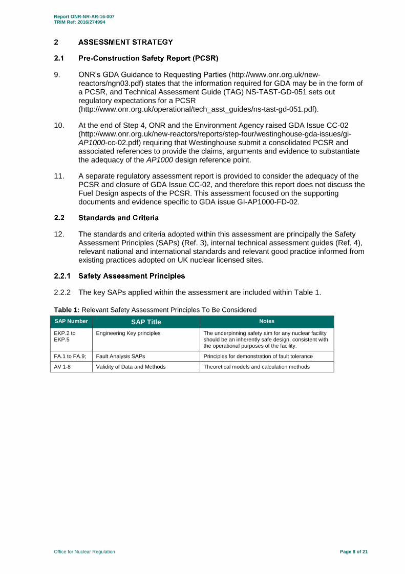
12. The standards and criteria adopted within this assessment are principally the Safety Assessment Principles (SAPs) (Ref. 3), internal technical assessment guides (Ref. 4), relevant national and international standards and relevant good practice informed from existing practices adopted on UK nuclear licensed sites.
2.2.2 The key SAPs applied within the assessment are included within Table 1.
Table 1: Relevant Safety Assessment Principles To Be Considered
SAP Number SAP Title Notes
EKP.2 to EKP.5
Engineering Key principles The underpinning safety aim for any nuclear facility should be an inherently safe design, consistent with the operational purposes of the facility.
FA.1 to FA.9; Fault Analysis SAPs Principles for demonstration of fault tolerance
AV 1-8 Validity of Data and Methods Theoretical models and calculation methods
Report ONR-NR-AR-16-007 TRIM Ref: 2016/274994
Office for Nuclear Regulation Page 9 of 21
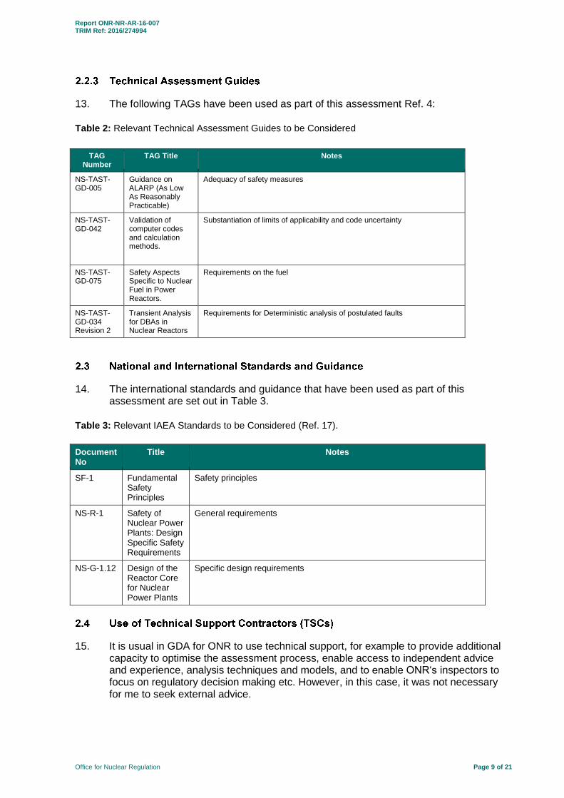
13. The following TAGs have been used as part of this assessment Ref. 4:
Table 2: Relevant Technical Assessment Guides to be Considered
TAG Number
TAG Title Notes
NS-TAST-GD-005
Guidance on ALARP (As Low As Reasonably Practicable)
Adequacy of safety measures
NS-TAST-GD-042
Validation of computer codes and calculation methods.
Substantiation of limits of applicability and code uncertainty
NS-TAST-GD-075
Safety Aspects Specific to Nuclear Fuel in Power Reactors.
Requirements on the fuel
NS-TAST-GD-034 Revision 2
Transient Analysis for DBAs in Nuclear Reactors
Requirements for Deterministic analysis of postulated faults
14. The international standards and guidance that have been used as part of this assessment are set out in Table 3.
Table 3: Relevant IAEA Standards to be Considered (Ref. 17).
Document No
Title Notes
SF-1 Fundamental Safety Principles
Safety principles
NS-R-1 Safety of Nuclear Power Plants: Design Specific Safety Requirements
General requirements
NS-G-1.12 Design of the Reactor Core for Nuclear Power Plants
Specific design requirements
15. It is usual in GDA for ONR to use technical support, for example to provide additional capacity to optimise the assessment process, enable access to independent advice and experience, analysis techniques and models, and to enable ONR‘s inspectors to focus on regulatory decision making etc. However, in this case, it was not necessary for me to seek external advice.
Report ONR-NR-AR-16-007 TRIM Ref: 2016/274994
Office for Nuclear Regulation Page 10 of 21
16. GDA requires the submission of an adequate, coherent and holistic generic safety case. Regulatory assessment cannot therefore be carried out in isolation as there are often safety issues of a multi-topic or cross-cutting nature. The following cross-cutting issues have been considered within this assessment:
17. Confirmation that guillotine fracture of the pipework is considered foreseeable within the design-basis of the plant required consultation with experts in Fault Studies and Structural Integrity disciplines.
18. The issue of break-opening times involved judgements on appropriate assumptions relating to material toughness and fracture mechanics. This required consultation with structural integrity experts to support my judgements.
Report ONR-NR-AR-16-007 TRIM Ref: 2016/274994
Office for Nuclear Regulation Page 11 of 21
19. The Westinghouse safety case for GDA issue GI-AP1000-FD-03 is outlined in Ref. 14.
20. Due to the high integrity classification of the AP1000 plant reactor cold leg inlet nozzle weld, a double-ended guillotine break at this location is classified as a low probability design-basis fault. This fault classification places such a break between the majority of design basis faults and beyond design basis faults. In order to provide adequate evidence to support Westinghouse’s claim that coolable geometry will be maintained in the core following a large-break loss-of-coolant accident (LB-LOCA), a detailed analysis has been completed using realistic operating assumptions applied to the standard Westinghouse LOCA analysis process.
21. The process undertaken consists of application of a sequence of four discrete modelling programs. Each uses input from the previous analysis to ultimately model the complete core response to the transient.
22. Westinghouse justified its assumptions for break-opening time based on a previous study Ref. 7. They argued that the break-opening time for circumferential breaks consists of two components:
The first component is the time interval it takes for a crack to propagate around the circumference of the pipe.
The second consists of the time it takes for the severed ends of the pipe to move away from each other.
23. Westinghouse argued that the break-opening time for longitudinal flaws is dependent primarily on crack propagation speed, while for circumferential breaks, the rate of separation of the severed ends is potentially the dominant factor.
24. Westinghouse has proposed a model relating break-opening area to time after the critical size is reached; based on test data for longitudinal breaks. Experiments on pressurized carbon and stainless steel pipes with artificial, longitudinal flaws were conducted. These tests measured crack propagation speeds along and perpendicular to the crack and permitted the development of a correlation for a break opening area as a function of time.
25. For circumferential cracks, Westinghouse has developed a method of evaluating break-opening time based on the inertia, hydraulic loads and stiffness of the system. The approach neglects the time taken for the crack to propagate around the circumference of the pipe. Westinghouse argued that the break opening time used in the analysis is suitably conservative.
26. Westinghouse have applied this analysis to the reactor vessel inlet and outlet nozzle welds and determined plant-specific opening times in the region of 20 ms. The vessel inlet nozzle failure is more limiting.
27. Westinghouse summarised its analysis of hydraulic loads in LOCA transients in Ref. 6.
28. The primary purpose of LOCA hydraulic-forces analysis is to generate the forcing functions and loads that occur as a result of a postulated LOCA. These hydraulic forcing functions and loads are calculated through the use of the MULTIFLEX evaluation model.
Report ONR-NR-AR-16-007 TRIM Ref: 2016/274994
Office for Nuclear Regulation Page 12 of 21
29. MULTIFLEX computes the pressure response of a system during a decompression transient. The transient pressure response can then be used to evaluate the system's overall dynamic structural response. The asymmetric pressure field in the downcomer annulus region of a PWR (due to a LOCA) can be calculated. This pressure field is integrated over the core support barrel area to obtain the total dynamic load on the core support barrel.
30. MULTIFLEX’s thermal-hydraulic system is modelled with an equivalent pipe network consisting of one-dimensional hydraulic channels, which define the actual system geometry. The actual system parameters of length, area, and volume are represented with the channel network.
31. The thermal-hydraulic portion of MULTIFLEX is based on the one-dimensional homogeneous-flow model; which is expressed as a set of mass, momentum, and energy conservation equations. These equations are quasi-linear first-order partial differential equations which are solved by the method of characteristics.
32. Coupled fluid-structure interaction is considered by accounting for the deflection of constraining boundaries, which are represented by separate spring-mass oscillator systems.
33. The models and correlations are described in documents generated over a number of decades and the qualification of the code has taken place as a result of a process of engagement with US Nuclear Regulatory Commission staff.
34. The loads on structural components are evaluated using a number of interface codes and the movement of the core barrel is predicted using the RESM model. The following components are represented in RESM:
The upper and lower heads, reactor vessel and the reactor vessel supports;
Lower reactor internal components: Core Barrel, Core Shroud, Lower Core Support Plate, Secondary Core Support Structure, and inserts, keys, and studs;
Upper reactor internal components: Upper Support Plate, Upper Core Plate, Upper Guide Tube, Lower Guide Tube, and Upper Support Column;
Super-element representation of the reactor coolant loop piping, pressurizer, and steam generators; and
The Integrated head package assembly.
35. Many complex three-dimensional structures are represented by assemblies of fundamental element types to simulate the stiffness, mass, damping, clearances, preloads and non-linear behaviour in the reactor vessel internals.
36. The core plate motions output by RESM provide the necessary input to the Westinghouse Grid Analysis Program (WEGAP) to assess resulting fuel assembly grid crush from the transient. Additionally, the core plate motions are used as input to the ANSYS model used to determine the maximum vertical force applied to a fuel assembly in the core.
37. WEGAP is a special-purpose mechanical analysis code; developed by Westinghouse to perform a time-history transient dynamic response analysis of a reactor core structure. WEGAP can perform a transient response analysis of a row of fuel
Report ONR-NR-AR-16-007 TRIM Ref: 2016/274994
Office for Nuclear Regulation Page 13 of 21
assemblies under various dynamic events. Impact forces at the core grid elevations can be computed from this program.
38. For the reported analysis, WEGAP was used to model the horizontal impact forces at each grid elevation, for each fuel assembly in the reactor core, during the transient. The maximum impact force for each grid in the core was identified and then compared to the known grid strength, to determine whether the grid would deform (crush) (potentially resulting in reduced coolant flow through the channels).
39. Westinghouse predicted that the depressurisation of the coolant results in loads sufficient to cause deformation on some components of the core barrel (notably alignment plates). This results in these components exceeding ASME design criteria, but not component ductility. On this basis, the components are judged to have been damaged but on balance are likely to continue to perform their safety function.
40. The loads on the fuel assemblies are calculated to cause buckling of the thin strips of the fuel-pin spacer grids, but only in certain fuel assemblies immediately adjacent to the core barrel. These assemblies experience the highest impact loads as a result of core barrel movement.
41. Westinghouse argued that buckling of the spacer grid straps in these assemblies is a benign event because the assemblies operate at lower-than-average power levels and therefore are not adversely affected by a small reduction in flow area. Westinghouse judged that corresponding increases in flow area adjacent to high-power assemblies are likely to benefit heat transfer.
42. Overall, Westinghouse concluded that core barrel movement in response to blow-down forces, is unlikely to have a significant impact on fuel performance in the worst-case LB-LOCA the AP1000 can credibly experience.
Report ONR-NR-AR-16-007 TRIM Ref: 2016/274994
Office for Nuclear Regulation Page 14 of 21
GI-AP1000-FD-02
43. This assessment has been carried out in accordance with HOW2 guide NS-PER-GD-014, “Purpose and Scope of Permissioning” (Ref. 2).
44. The scope of the assessment is outlined in my assessment plan (Ref. 1).
45. The cold-leg nozzle weld receives significant attention to ensure adequate quality and Westinghouse considered that it might be possible to make arguments to exclude the analysis of the consequences of failure from the design basis of the plant, but ONR does not encourage this approach (see SAP because the burden of in-service inspection necessary to support this approach would involve operator exposure to radiation. Moreover from a defence-in-depth perspective, we prefer the plant to be engineered to be fault tolerant (SAP .
46. In the AP1000-FD-02 case, the question being addressed by the GDA issue is whether the core barrel is stiff enough to adequately resist the pressure forces associated with primary circuit depressurisation and whether the fuel assembly grid straps are thick enough to resist buckling due to impact loads caused by core barrel movement.
47. The determination of whether there is a need for design-basis fault assessment of a LOCA (caused by fracture of one of the large pipes within the primary circuit) is beyond the scope of this assessment. I have taken the accepted position that the fault is within the design basis and not assessed the estimate of the likely event frequency, except that I accept such an event is likely to be low frequency (in the region of 1E-5/yr). This is significant to my assessment because NS-TAST-GD-34 (Ref. 4) recognises that the level of confidence required in the analysis is dependent on the frequency of the fault sequence under consideration.
48. I have therefore examined the analysis to determine whether it meets the requirements of SAPs FA.1-9 and demonstrates that there is high confidence that the fuel is likely to be protected during the fault (taking the likely fault frequency into account).
49. It is ONR’s expectation that the computer codes used in the analysis must have been adequately verified and validated to a satisfactory standard prior to their use in plant safety analyses (see SAP AV.1 to 4). I take some comfort from the fact that the methods have been used in license submissions within the USA. However, I have carried out my own sampling of the modelling. Moreover I have sampled the documentation for the computer codes used in the analysis of the hydraulics against the expectations of SAP AV.5.
50. I judge that the codes used for the analysis of dynamic loading on mechanical structures employ straightforward principles of mechanics and therefore I have considered the codes themselves in less detail and I have focused on whether the assumptions employed are reasonable.
51. The original safety case presented in GDA Step 4 for the consequences of a large-break loss-of-coolant accident (LB-LOCA) analysed the cladding temperatures expected in the fault on the assumption that the core geometry was unaffected by the fault. I observed that this assumption was not adequately demonstrated and raised issue GI-AP1000-FD-02 expecting a suitable justification (potentially based on changes to core components).
52. The justification has taken the form of deterministic analysis of the most limiting condition postulated within the design basis of the plant: An offset guillotine break of
Report ONR-NR-AR-16-007 TRIM Ref: 2016/274994
Office for Nuclear Regulation Page 15 of 21
the cold leg of the primary circuit at the vessel inlet nozzle weld. The hot-leg break has been omitted from consideration on the basis that should it break, the offset of the pipes is limited by constraints on the structures, so that the opening would be significantly smaller (Ref. 14). This argument appears reasonable. I also note that hot-leg breaks are not as severe a challenge to fuel coolability and it is my experience that the hot-leg nozzle welds have been found to suffer fewer problems during operation.
53. The analysis used to answer the GDA issue has a number of technical components:
The magnitude of the pressure disturbance passing through the reactor depends upon the time taken for the break to open.
The impact loads experienced by the fuel assemblies depend upon the modelling of the elastic and plastic response of the core barrel when subjected to the transient hydraulic forces.
The effect on core geometry depends upon the modelling of fuel assembly buckling.
54. These topics are addressed in turn below.
55. I have examined the arguments on break opening time presented in Ref. 8. Westinghouse considers the opening of a longitudinal crack to be determined principally by the crack propagation speed and Westinghouse bases its estimate of this on limited experimental data. However, this data are sufficient to confirm that this type of crack is not likely to be limiting. I also judge that significant longitudinal defects in the cold leg are unlikely.
56. The more limiting case is a circumferential crack; there is the potential for the crack to propagate in regions of less certain metallurgy and residual stress (in particular the heat-affected zone adjacent to the nozzle weld). In this case, Westinghouse has not taken credit for the time in which the crack propagates and has based the case on the inertia of the primary-circuit components and the jet forces (Ref. 8). I judge that this approach is substantially conservative and therefore acceptable.
57. The analysis of the hydraulic loads experienced by the core barrel was carried out by Westinghouse using the MULTIFLEX computer code (Ref. 9). This code has been used in the past for analysis of loading on the Sizewell B core barrel and I have previously compared MULTIFLEX predictions for Sizewell B with those of the RELAP 5 computer code (which is used for the modelling of LOCA more generally). However, I judged that this analysis is sufficiently important for me to sample the code qualification. I therefore raised RQ-AP1000-1401 requesting Westinghouse to provide all necessary supplementary information to justify that the analysis adequately represents the physical processes and provides a realistic representation of the AP1000 plant. Westinghouse’s response is provided in Ref. 6 and further supporting information is found in Refs. 7 and 8.
58. The bulk of the description and justification of the MULTIFLEX model is found in Ref. 9. The model is applied for the first few seconds of the primary-circuit depressurisation. The hydraulic model is relatively simple and employs the homogeneous equilibrium flow approximation. I judge that at the Reynolds Numbers of concern, the use of homogeneous two-phase flow modelling is likely to be adequate to represent flows remote from the break. I judge that a one-dimensional approach is likely to be adequate over the bulk of the solution domain used in the model.
Report ONR-NR-AR-16-007 TRIM Ref: 2016/274994
Office for Nuclear Regulation Page 16 of 21
59. The calculation for previous reactor designs has historically used pessimised fuel assembly pressure loss data, but in an attempt to be more realistic, Ref. 5 uses nominal values. I have examined the uncertainty allowances traditionally applied and I judge that these are excessive given current knowledge. In practice, the pressure loss associated with a fuel assembly is reasonably well known due to the need to ensure compatibility between fuel designs co-resident in core (see for example the results of ONR research presented in Ref. 15). Westinghouse has not explicitly accounted for the uncertainty in pressure loss and implicitly argues that this can be traded off against significant pessimisms in other aspects of the calculation.
60. I judge that the uncertainty associated with the new model is not large compared with the pessimism introduced by use of a conservative break-opening time and therefore I consider the approach reasonable given the fault return frequency.
61. The flow solution employs the method of characteristics and is explicit in the time domain and therefore I asked about the influence of time step length. Initial calculations suffered from a degree of numerical noise. However, Westinghouse carried out nodalisation studies to see if the noise was related to node spacing and the time step sizes (Ref. 6 & 7). They also introduced an element of damping into the modelling of the core barrel which helped reduce the oscillations. This was less than the damping justified for modelling core components and therefore remains conservative (Ref. 10).
62. Since the MULTIFLEX model is essentially 1D, it introduces some approximations into the 2D pressure field present in the downcomer. A review by US Nuclear Regulatory Commission is included in Ref. 9. It concluded that the 1D model neglected the dissipation of the pressure wave as it travelled down the downcomer and is therefore conservative. I take comfort from this finding.
63. In view of potential inherent conservatisms in the methodology and the employment of sensitivity studies to demonstrate numerically accurate solutions, I judge that the approach is adequate when compared to the expectations on numerical accuracy set out in NS-TAST-GD-42 and SAP AV.2.
64. I focused my attention on the modelling of the region of the pipe adjacent to the break because I judge that the physics of the model in this region is likely to be important. The model employed is a conservative fit to critical flow data based on a discharge coefficient and a defined “back pressure”. This model is relatively crude and not well documented, in the material supplied, so I asked regulatory query RQ-AP1000-1674; requesting supplementary information to justify parametric data currently used, including information on qualification of the model parameters.
65. In Ref. 9, Westinghouse claims that the calculated sonic velocity is consistent with that of ASME steam tables. The supplementary information supplied in Ref 16 shows reasonable agreement between the downcomer pressure response seen in integral tests and MULTIFLEX predictions. This confirms that the modelling is adequate.
66. Overall, I accept that the model is adequate to represent the physical process occurring in the fault in line with the requirement of SAP AV.2.
67. The response to the calculated pressure loads is evaluated by the Reactor Equipment System Model (RESM). This is a finite-element model executed within the ANSYS® code system Ref. 11.
Report ONR-NR-AR-16-007 TRIM Ref: 2016/274994
Office for Nuclear Regulation Page 17 of 21
68. The model represents the internals as a set of shells and beam elements, with stiffness responses derived from more detailed finite-element models of components. This appears to be a reasonable approach. The model represents the reactor internals in a reasonable amount of detail, but omits the vessel shell itself.
69. Westinghouse have performed sensitivity studies and conclude that it is conservative to exclude reactor pressure-vessel shell deflection from the study because any interaction will be one of nullification of the pressure wave (through cancelling effects) as the wave resolves itself in the system. This justification appears reasonable and I regard the approach adopted to address the issue as consistent with my expectations.
70. Based on my sampling, I judge that the stiffness of individual elements is represented in the level of detail required, including a reasonable representation of non-linear response to load where required.
71. The analysis does not demonstrate that the failure of individual components in the core barrel is precluded by compliance with code, but demonstrates that safety margins to component ductility limits are preserved. Westinghouse has examined the loads on dowels and pins in particular, and where the component has been shown to fail, its confinement function has conservatively been removed from the model.
72. I consider this practice acceptable based on the low-frequency of the event and also I judge that avoiding the possibility of limited damage to the core barrel in this fault is not absolutely necessary to avoiding a degraded core.
73. Overall, I am impressed with the detail of the RESM model and Westinghouse’s systematic approach to its application.
74. The analysis of loads on fuel assemblies is carried out using models of rows of fuel assemblies (Ref. 12, 14). I considered whether the analysis includes representation of component degradation during exposure. Account is taken of fuel assembly spacer-grid relaxation with irradiation and the analysis does contain a degree of conservatism because it does not represent the irradiation growth of fuel assembly spaced grids; which has the effect of reducing the spacing between fuel assemblies and hence the room to move. Additionally, Westinghouse gave particular consideration to the beginning of life condition; which it models appropriately using the as-manufactured data.
75. The structural analysis of the fuel assembly aims at determining the margin between the load transmitted by the fuel assembly spacer grids and the load required to buckle a row of spacer grid straps or to snap a fuel pin. The load limits for spacer grids are bounding.
76. I accept that the objective of preventing plastic deformation of spacer-grid straps does not extend to precluding spacer buckling in fuel assemblies placed on the periphery of the core. These assemblies are too low powered to experience significant fuel damage in the fault and a modest loss of flow area, caused by buckling of the spacers, is unlikely to challenge safety limits. This argument has been made in the past for Sizewell B and ONR has considered it acceptable. I therefore accept that buckling in these assemblies is likely to be benign.
77. The preliminary analysis breached the axial loads for which the fuel assembly had been qualified and Westinghouse demonstrated that a safety margin existed to fuel damage by testing a fuel assembly at higher axial loads (Ref. 13). In essence Westinghouse has shown that the barrel motion does not impact the fault progression. This meets my expectations.
Report ONR-NR-AR-16-007 TRIM Ref: 2016/274994
Office for Nuclear Regulation Page 18 of 21
78. Westinghouse has demonstrated that the plant can tolerate the depressurisation of the primary coolant and the resulting movement of the core barrel without unacceptable levels of damage to the reactor internals and the fuel (Ref. 12).
79. The safety margins in this analysis are reduced compared to that normally accepted for this type of assessment, but I judge that a number of key conservatisms remain sufficient to have an adequate level of confidence in the results (bearing in mind the low likelihood of the event).
80. I also note that should Westinghouse have predicted buckling of spacer grids in high-power assemblies, the option of demonstrating that this is tolerable would have remained. The approach has been to assume the worst in the absence of detailed information to justify otherwise. This is referred to as application of the precautionary principle and is appropriate in consideration of major hazards.
81. Based on the above, I conclude that modifications to the core barrel or fuel assembly spacer grids are not required to reduce the risk to reasonable levels.
82. This analysis was incorporated into the safety case in the appropriate chapters of the PCSR. See Ref. 18. The calculations are not sensitive to the core design and therefore have no impact on the core reload provided that the fuel assembly mechanical design is not significantly changed. Ref. 14 is cited from topical reports; supporting the fault study arguments in Chapter 9 of the PCSR. I am therefore satisfied that it has been incorporated into the UK AP1000 safety case.
83. This analysis is extremely specialist and therefore is mostly not subject to codes and standards. However, the structural analysis of the core components has been carried out in accordance with ASME design criteria (Ref. 12) as an initial sift to determine whether there is a likelihood of component failure.
84. These criteria relate allowable bending, membrane and local stresses to yield and failure stresses. They are widely applied in the nuclear industry internationally and the approach meets my expectations.
85. The code documentation has been considered in the context of NS-TAST-GD-51. It is essential that the safety case documentation is clear and logically structured so that the information is easily accessible to those who need to use it. This includes designers, operations and maintenance staff, technical personnel and managers who are accountable for safety.
86. The high-level documentation provided a good description of the issues and generally an adequate map of the lower-level documents. I judge that overall it meets the requirements of SAP. AV.5. However, some of the material presented is old and had been subject to additions and commentaries (including by the US Nuclear Regulatory Commission) which brought it up to an adequate technical standard. Some of these documents would benefit from revision and restructuring, but on the basis that the user base is limited to Westinghouse experts who are likely to be familiar with the issues, this is not a significant shortfall in this case.
87. This report presents the findings of the assessment of GDA Issue GI-AP1000-FD-02 relating to the AP1000 GDA closure phase.
Report ONR-NR-AR-16-007 TRIM Ref: 2016/274994
Office for Nuclear Regulation Page 19 of 21
88. Westinghouse have completed the analysis of the effect of the coolant flow during a primary-circuit depressurisation; caused by a postulated guillotine failure of the main pipework.
89. I am satisfied that the methods employed are appropriate and am content that they have demonstrated that the fuel and core components will not suffer impact damage sufficient to lead to a significant increment in safety hazard.
90. I found no significant shortcomings in the submission and some of the documentation was of a high standard. I have reservations about the coherence of the code qualification documentation and judge that this would benefit from revision, but on the basis that the user base is limited to Westinghouse experts who are likely to be familiar with them, this is not a significant shortfall in this case.
91. To conclude, I find that this aspect of the AP1000 safety case is adequate and GDA issue GI-AP1000-FD-02 can be closed.
Report ONR-NR-AR-16-007 TRIM Ref: 2016/274994
Office for Nuclear Regulation Page 20 of 21
1. UK AP1000 Assessment Plan for Closure GDA Fuel Design Issues 1 to 3, April
2015. TRIM REF 2015/149262. 2. ONR HOW2 Guide NS-PER-GD-014 Revision 4 - Purpose and Scope of
Permissioning. July 2014. http://www.onr.org.uk/operational/assessment/index.htm
3. Safety Assessment Principles for Nuclear Facilities. 2014 Edition Revision 0.
http://www.onr.org.uk/saps/saps2014.pdf.
4. Technical Assessment Guides Guidance on ALARP (As Low As Reasonably Practicable), NS-TAST-GD-005. Transient Analysis for DBAs in Nuclear Reactors, NS-TAST-GD-034 Validation of Computer Codes and Calculation Methods, NS-TAST-GD-042 Rev 2. Safety Aspects Specific to Nuclear Fuel in Power Reactors, NS-TAST-GD-075.
http://www.onr.org.uk/operational/tech_asst_guides/index.htm
5. AP1000-UK LBLOCA Forces for FD.02, UKP-SSAR-GSC-013, Revision 1, 2016, TRIM REF 2015/406884.
6. LOCA Forces Overview (Response to RQ-AP1000-1401), FORCES-1 Rev 2,
30th October 2015. TRIM REF 2015/406850.
7. Hydrodynamic Forces for a Postulated Reactor Coolant Pump Locked Rotor Transient Using the MULTIFLEX Code, APP-SSAR-GSC-197, February 2015. TRIM REF 2015/406876.
8. Justification for Increasing Postulated Break Opening Times in Westinghouse
Pressurized Water Reactors, WCAP-14748-P-A Revision 1, August 2001, TRIM REF 2014/449963.
9. MULTIFLEX A Fortran IV Computer Program for Analyzing Thermal Hydraulic
Structure System Dynamics, WCAP-8708-PA-V1, Westinghouse 1977, TRIM REF 2011/183543.
10. LOCA Forces Guidance on the Use of Damping in MULTIFLEX Analysis
(Response to RQ-AP1000-1401), LTR-LIS-15-247, 30th October 2015, TRIM REF 2015/406863.
11. AP1000 UK RESM - Large Break (LB) Loss-of Coolant Accident (LOCA) Analysis,
UKP-MI01-S3C-001, 20 July 2016, TRIM REF 2016/291908.
12. AP1000 Fuel Assembly Seismic/LOCA Analysis in Support of the UK LBLOCA Project, CN-NRFE-16-2, - 20 July 2016, TRIM REF 2016/291934.
13. AP1000 Fuel Assembly Vertical LOCA Forces Evaluation in Support of the UK
LBLOCA Project, CN-NRFE-15-3, 20 July 2016, TRIM REF 2016/291924.
14. UK AP1000 Fuel Tolerability of Depressurisation of the Primary Circuit Assessment, UKP-GW-GLR-035, August 2016, TRIM REF 2016/323268.
Report ONR-NR-AR-16-007 TRIM Ref: 2016/274994
Office for Nuclear Regulation Page 21 of 21
15. Study of local heat transfer coefficient on peripheral PWR assembly fuel in the event of touching spacer grids, ONR RRR-013 TSG Final Report, November 2016, TRIM REF 2016/455411.
16. Analysis of HDR Blowdown Experiment for Fluid-Structure Interactions with
MULTIFLEX (Response to RQ-AP1000-1710), NNP-JNE-001387, November 2016, TRIM REF 2016/439936.
17. IAEA guidance:
Fundamental Safety Principles. Safety Fundamentals. IAEA Safety Standards Series No. SF-1. . IAEA. Vienna, 2006.
Safety of Nuclear Power Plants: Design. Safety Requirements. International Atomic Energy Agency (IAEA). Safety Standards Series No. NS-R-1. IAEA. Vienna, 2000.
Design of the Reactor Core for Nuclear Power Plant, IAEA Safety Guide, NS-G- 1.12, IAEA Vienna 2005.
www.iaea.org
18. PCSR Markups, UKP-GW-GLR-035_Revision 0, August 2016, TRIM REF 2016/323276