Embed Size (px)
Citation preview
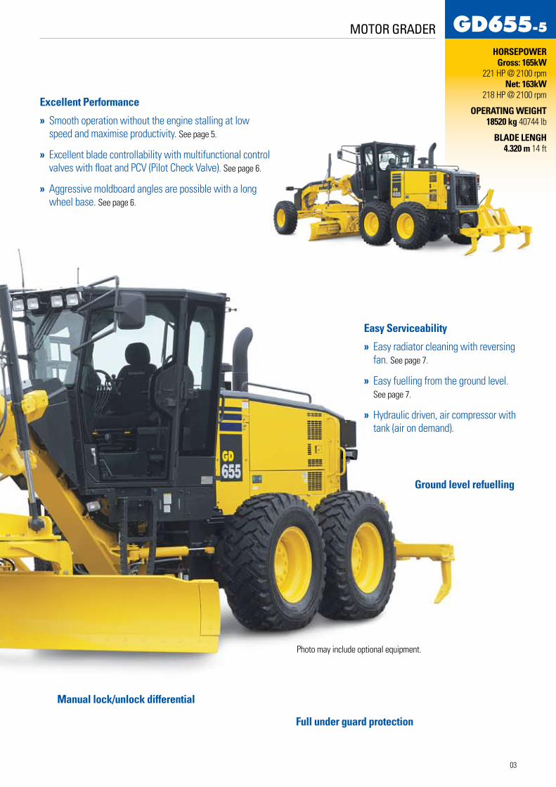
HORSEPOWER Gross: 165kW 221 HP @ 2100 rpm
Net: 163kW 218 HP @ 2100 rpm
OPERATING WEIGHT 18520 kg 40744 lb
BLADE LENGH 4.320 m 14 ft
MO
TOR
GR
AD
ER
GD 655
Photo may include optional equipment.
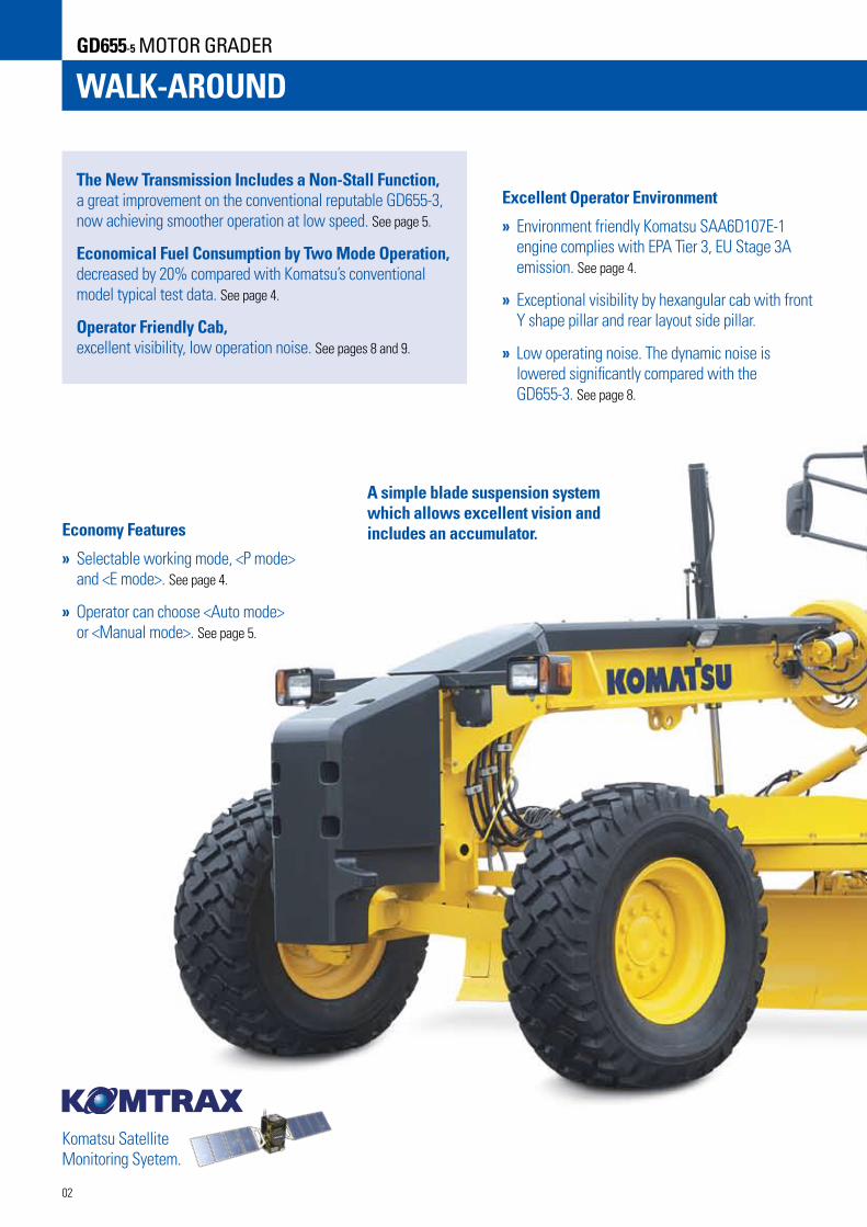
WALK-AROUNDGD655-5 MOTOR GRADER
The New Transmission Includes a Non-Stall Function, a great improvement on the conventional reputable GD655-3, now achieving smoother operation at low speed. See page 5.
Economical Fuel Consumption by Two Mode Operation, decreased by 20% compared with Komatsu’s conventional model typical test data. See page 4.
Operator Friendly Cab, excellent visibility, low operation noise. See pages 8 and 9.
Excellent Operator Environment
» Environment friendly Komatsu SAA6D107E-1 engine complies with EPA Tier 3, EU Stage 3A emission. See page 4.
» Exceptional visibility by hexangular cab with front Y shape pillar and rear layout side pillar.
» Low operating noise. The dynamic noise is lowered significantly compared with the GD655-3. See page 8.
Economy Features
» Selectable working mode, <P mode> and <E mode>. See page 4.
» Operator can choose <Auto mode> or <Manual mode>. See page 5.
A simple blade suspension system which allows excellent vision and includes an accumulator.
Komatsu Satellite Monitoring Syetem.
02
MOTOR GRADER
Excellent Performance
» Smooth operation without the engine stalling at low speed and maximise productivity. See page 5.
» Excellent blade controllability with multifunctional control valves with float and PCV (Pilot Check Valve). See page 6.
» Aggressive moldboard angles are possible with a long wheel base. See page 6.
Easy Serviceability
» Easy radiator cleaning with reversing fan. See page 7.
» Easy fuelling from the ground level. See page 7.
» Hydraulic driven, air compressor with tank (air on demand).
Manual lock/unlock differential
Full under guard protection
Ground level refuelling
Photo may include optional equipment.
HORSEPOWER Gross: 165kW
221 HP @ 2100 rpm Net: 163kW
218 HP @ 2100 rpm
OPERATING WEIGHT 18520 kg 40744 lb
BLADE LENGH 4.320 m 14 ft
03
F1
F2
F3
F4
F5
F6
F7
F8
R1
R2
R3
R4
AUTO
180
200
218
180
200
MANU.
180
200
218
180
200
AUTO
145
180
200
145
180
MANU.
145
180
200
145
180
P E
F1F2F3F4F5F6F7F8R1R2R3R4
AUTO MANU. AUTO MANU.P E
kW (HP)
: In lockup state (torque converter is not in use) : As the machine speed increases, torque converter state changes to lockup state. : In torque converter state : Automatic gear shift
Position of gear shift lever
F-1 F-2 F-3 F-4 R-1
R-1
R-2
R-3
R-4
R-2 R-3 R-4F-5 F-6 F-7 F-8
118 (158)
131(176)
144(193)
118 (158)
131(176)
118 (158)
131(176)
118 (158)
104(140)
118 (158)
104(140)
131(176)
118 (158)
104(140)
118 (158)
104(140)
131(176)
144(193)
118 (158)
131(176)
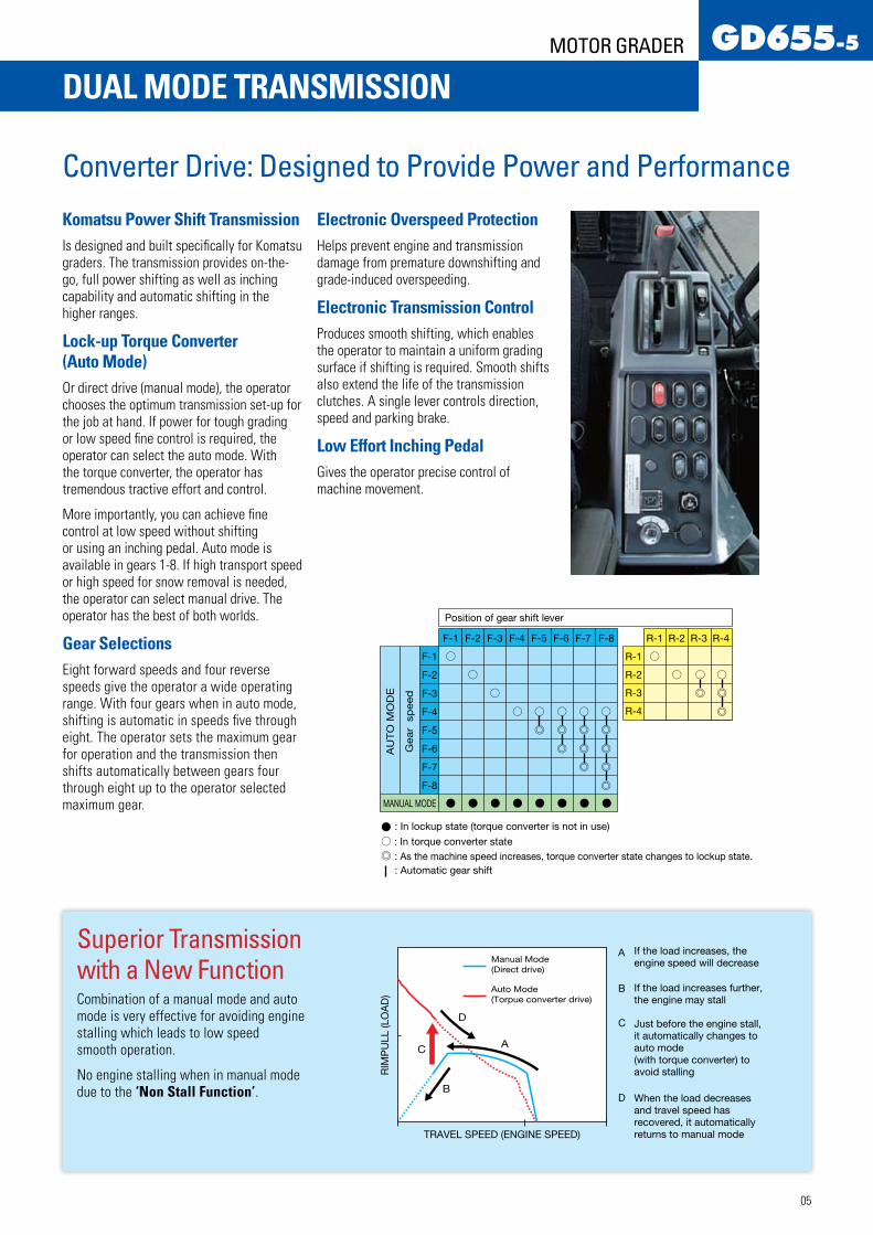
Manual Mode(Direct drive)
If the load increases, theengine speed will decrease
If the load increases further,the engine may stall
Just before the engine stall, it automatically changes to auto mode (with torque converter) to avoid stalling
When the load decreases and travel speed hasrecovered, it automatically returns to manual mode
Auto Mode(Torpue converter drive)
TRAVEL SPEED (ENGINE SPEED)
RIM
PU
LL (L
OA
D)
A
A
B
B
C
C
D
D
MANUAL MODE
F-1
F-2
F-3
F-4
F-5
F-6
F-7
F-8
AU
TO
MO
DE
Gear
sp
eed
ECOLOGY FEATURES
Komatsu TechnologyKomatsu develops and produces all major components, such as engines, electronics and hydraulic components in house.
Since all components can be matched, efficiencies are increased achieving high levels of productivity and ecology. With this “Komatsu Technology”, and through customer feedback, Komatsu is achieving great advancements in technology.
The result is a new generation of high performance and environment friendly machines.
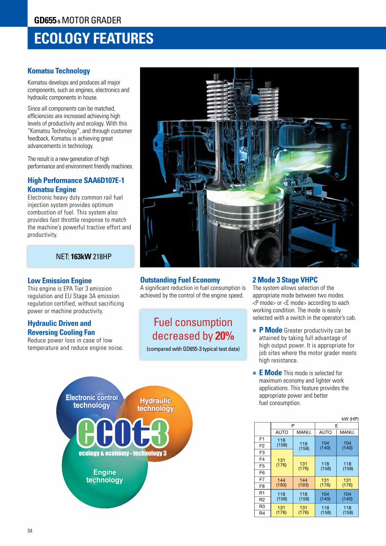
High Performance SAA6D107E-1 Komatsu Engine Electronic heavy duty common rail fuel injection system provides optimum combustion of fuel. This system also provides fast throttle response to match the machine’s powerful tractive effort and productivity. NET: 163kW 218HP Low Emission Engine This engine is EPA Tier 3 emission regulation and EU Stage 3A emission regulation certified, without sacrificing power or machine productivity.
Hydraulic Driven and Reversing Cooling Fan Reduce power loss in case of low temperature and reduce engine noise.
Outstanding Fuel Economy A significant reduction in fuel consumption is achieved by the control of the engine speed.
2 Mode 3 Stage VHPC The system allows selection of the appropriate mode between two modes <P mode> or <E mode> according to each working condition. The mode is easily selected with a switch in the operator’s cab.
» P Mode Greater productivity can be attained by taking full advantage of high output power. It is appropriate for job sites where the motor grader meets high resistance.
» E Mode This mode is selected for maximum economy and lighter work applications. This feature provides the appropriate power and better fuel consumption.
Fuel consumption decreased by 20%
(compared with GD655-3 typical test data)
04
GD655-5 MOTOR GRADER
DUAL MODE TRANSMISSION
Converter Drive: Designed to Provide Power and Performance
Komatsu Power Shift TransmissionIs designed and built specifically for Komatsu graders. The transmission provides on-the-go, full power shifting as well as inching capability and automatic shifting in the higher ranges.
Lock-up Torque Converter (Auto Mode)Or direct drive (manual mode), the operator chooses the optimum transmission set-up for the job at hand. If power for tough grading or low speed fine control is required, the operator can select the auto mode. With the torque converter, the operator has tremendous tractive effort and control.
More importantly, you can achieve fine control at low speed without shifting or using an inching pedal. Auto mode is available in gears 1-8. If high transport speed or high speed for snow removal is needed, the operator can select manual drive. The operator has the best of both worlds.
Gear SelectionsEight forward speeds and four reverse speeds give the operator a wide operating range. With four gears when in auto mode, shifting is automatic in speeds five through eight. The operator sets the maximum gear for operation and the transmission then shifts automatically between gears four through eight up to the operator selected maximum gear.
Electronic Overspeed ProtectionHelps prevent engine and transmission damage from premature downshifting and grade-induced overspeeding.
Electronic Transmission ControlProduces smooth shifting, which enables the operator to maintain a uniform grading surface if shifting is required. Smooth shifts also extend the life of the transmission clutches. A single lever controls direction, speed and parking brake.
Low Effort Inching PedalGives the operator precise control of machine movement.
Superior Transmission with a New FunctionCombination of a manual mode and auto mode is very effective for avoiding engine stalling which leads to low speed smooth operation.
No engine stalling when in manual mode due to the ‘Non Stall Function’.
F1
F2
F3
F4
F5
F6
F7
F8
R1
R2
R3
R4
AUTO
180
200
218
180
200
MANU.
180
200
218
180
200
AUTO
145
180
200
145
180
MANU.
145
180
200
145
180
P E
F1F2F3F4F5F6F7F8R1R2R3R4
AUTO MANU. AUTO MANU.P E
kW (HP)
: In lockup state (torque converter is not in use) : As the machine speed increases, torque converter state changes to lockup state. : In torque converter state : Automatic gear shift
Position of gear shift lever
F-1 F-2 F-3 F-4 R-1
R-1
R-2
R-3
R-4
R-2 R-3 R-4F-5 F-6 F-7 F-8
118 (158)
131(176)
144(193)
118 (158)
131(176)
118 (158)
131(176)
118 (158)
104(140)
118 (158)
104(140)
131(176)
118 (158)
104(140)
118 (158)
104(140)
131(176)
144(193)
118 (158)
131(176)
Manual Mode(Direct drive)
If the load increases, theengine speed will decrease
If the load increases further,the engine may stall
Just before the engine stall, it automatically changes to auto mode (with torque converter) to avoid stalling
When the load decreases and travel speed hasrecovered, it automatically returns to manual mode
Auto Mode(Torpue converter drive)
TRAVEL SPEED (ENGINE SPEED)
RIM
PU
LL (L
OA
D)
A
A
B
B
C
C
D
D
MANUAL MODE
F-1
F-2
F-3
F-4
F-5
F-6
F-7
F-8
AU
TO
MO
DE
Gear
sp
eed
05
MOTOR GRADER
F1
F2
F3
F4
F5
F6
F7
F8
R1
R2
R3
R4
AUTO
180
200
218
180
200
MANU.
180
200
218
180
200
AUTO
145
180
200
145
180
MANU.
145
180
200
145
180
P E
F1F2F3F4F5F6F7F8R1R2R3R4
AUTO MANU. AUTO MANU.P E
kW (HP)
: In lockup state (torque converter is not in use) : As the machine speed increases, torque converter state changes to lockup state. : In torque converter state : Automatic gear shift
Position of gear shift lever
F-1 F-2 F-3 F-4 R-1
R-1
R-2
R-3
R-4
R-2 R-3 R-4F-5 F-6 F-7 F-8
118 (158)
131(176)
144(193)
118 (158)
131(176)
118 (158)
131(176)
118 (158)
104(140)
118 (158)
104(140)
131(176)
118 (158)
104(140)
118 (158)
104(140)
131(176)
144(193)
118 (158)
131(176)
Manual Mode(Direct drive)
If the load increases, theengine speed will decrease
If the load increases further,the engine may stall
Just before the engine stall, it automatically changes to auto mode (with torque converter) to avoid stalling
When the load decreases and travel speed hasrecovered, it automatically returns to manual mode
Auto Mode(Torpue converter drive)
TRAVEL SPEED (ENGINE SPEED)
RIM
PU
LL (L
OA
D)
A
A
B
B
C
C
D
D
MANUAL MODE
F-1
F-2
F-3
F-4
F-5
F-6
F-7
F-8
AU
TO
MO
DE
Gear
sp
eed
ADVANCED CONTROL FEATURES
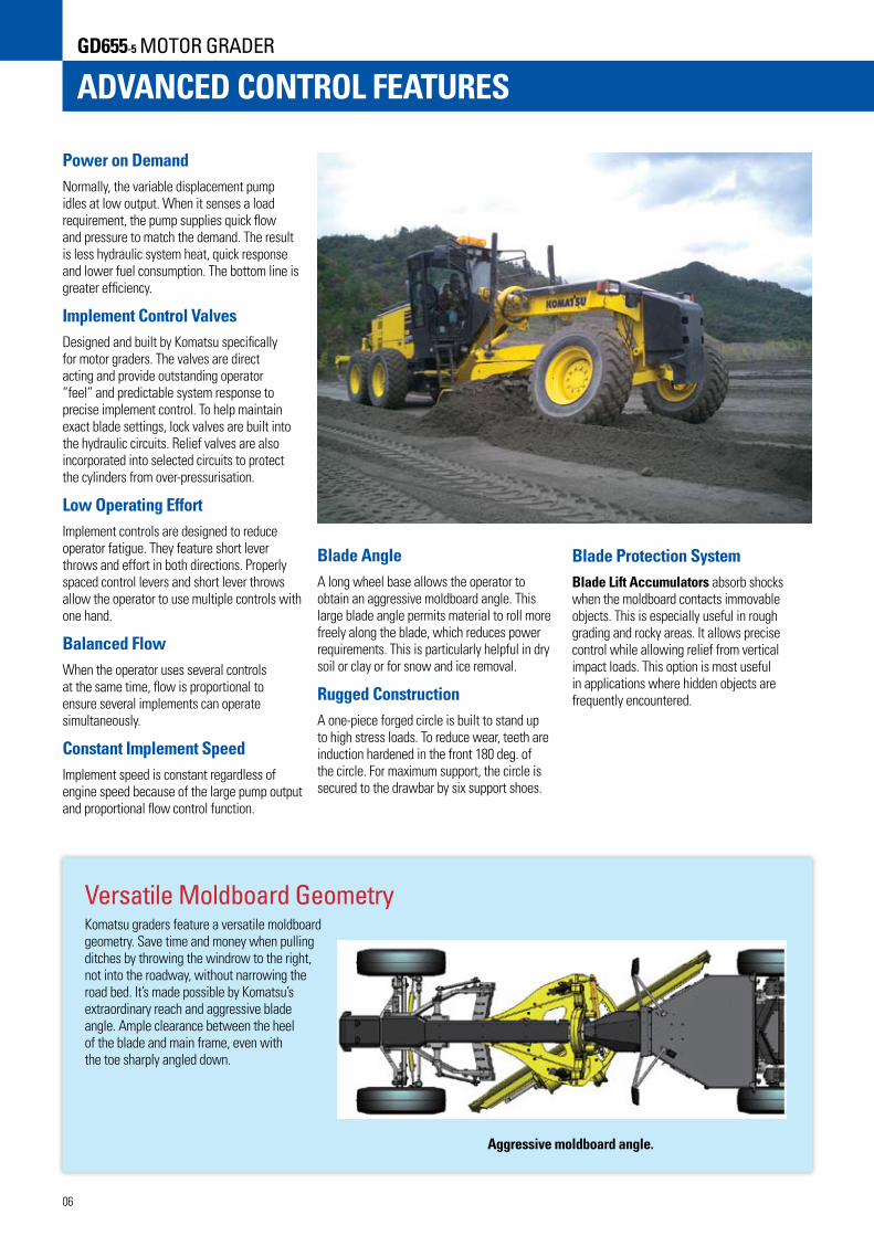
Power on DemandNormally, the variable displacement pump idles at low output. When it senses a load requirement, the pump supplies quick flow and pressure to match the demand. The result is less hydraulic system heat, quick response and lower fuel consumption. The bottom line is greater efficiency.
Implement Control ValvesDesigned and built by Komatsu specifically for motor graders. The valves are direct acting and provide outstanding operator “feel” and predictable system response to precise implement control. To help maintain exact blade settings, lock valves are built into the hydraulic circuits. Relief valves are also incorporated into selected circuits to protect the cylinders from over-pressurisation.
Low Operating EffortImplement controls are designed to reduce operator fatigue. They feature short lever throws and effort in both directions. Properly spaced control levers and short lever throws allow the operator to use multiple controls with one hand.
Balanced FlowWhen the operator uses several controls at the same time, flow is proportional to ensure several implements can operate simultaneously.
Constant Implement SpeedImplement speed is constant regardless of engine speed because of the large pump output and proportional flow control function.
Blade AngleA long wheel base allows the operator to obtain an aggressive moldboard angle. This large blade angle permits material to roll more freely along the blade, which reduces power requirements. This is particularly helpful in dry soil or clay or for snow and ice removal.
Rugged ConstructionA one-piece forged circle is built to stand up to high stress loads. To reduce wear, teeth are induction hardened in the front 180 deg. of the circle. For maximum support, the circle is secured to the drawbar by six support shoes.
Blade Protection SystemBlade Lift Accumulators absorb shocks when the moldboard contacts immovable objects. This is especially useful in rough grading and rocky areas. It allows precise control while allowing relief from vertical impact loads. This option is most useful in applications where hidden objects are frequently encountered.
Versatile Moldboard GeometryKomatsu graders feature a versatile moldboard geometry. Save time and money when pulling ditches by throwing the windrow to the right, not into the roadway, without narrowing the road bed. It’s made possible by Komatsu’s extraordinary reach and aggressive blade angle. Ample clearance between the heel of the blade and main frame, even with the toe sharply angled down.
06
GD655-5 MOTOR GRADER
Aggressive moldboard angle.

MAINTENANCE FEATURES
Superior Serviceability
Easy Access to Service Areas» Large hinged lockable doors are standard
and provide easy access to the engine and radiator service points. Spin-on filters can be changed quickly.
» The fuse panel is located in the cab. Circuits and fuse sizes are clearly identified.
» The tandem oil check point is conveniently located at the end of the tandem.
» The service meter is located in the electronic monitoring system.
» Refuelling from the ground is easy.
» Engine oil, hydraulic oil and coolant drains are eco friendly positioned with excellent accessibility.
Easy Radiator Cleaning with Reversing FanDust stuck to the radiator and cooler fins is blown off with reversal of the hydraulic drive fan.
Power Train ComponentsWith a modular design, you can remove the engine, transmission or final drives independently for quick service.
Character Display is Easy to SeeDuring normal operation, the service meter/odometer is displayed in this area. If abnormality or machine overload occurs, or if machine maintenance and inspection are required, action codes appear on the display to allow the operator to take appropriate action.
Adjustment-free Oil Disc BrakesKomatsu designs and builds multiple-disc brakes that are completely sealed and adjustment-free. The brakes are immersed in oil, and are hydraulically actuated. A fully hydraulic brake system eliminates problems associated with air systems. The large braking surface provides dependable braking capability and increased life before a rebuild is required.
Friendly EnvironmentThe engine and transmission are rubber-mounted to transmit less engine noise and vibtration to the operator and extend component life. A lead-free aluminium core is used for the radiator to comply with global environmental requirements.
Tool Box
Spin-on Transmission Filter
Console with central warning lamp. Internal monitoring system with error codes appearing in the display screen.
07
MOTOR GRADER
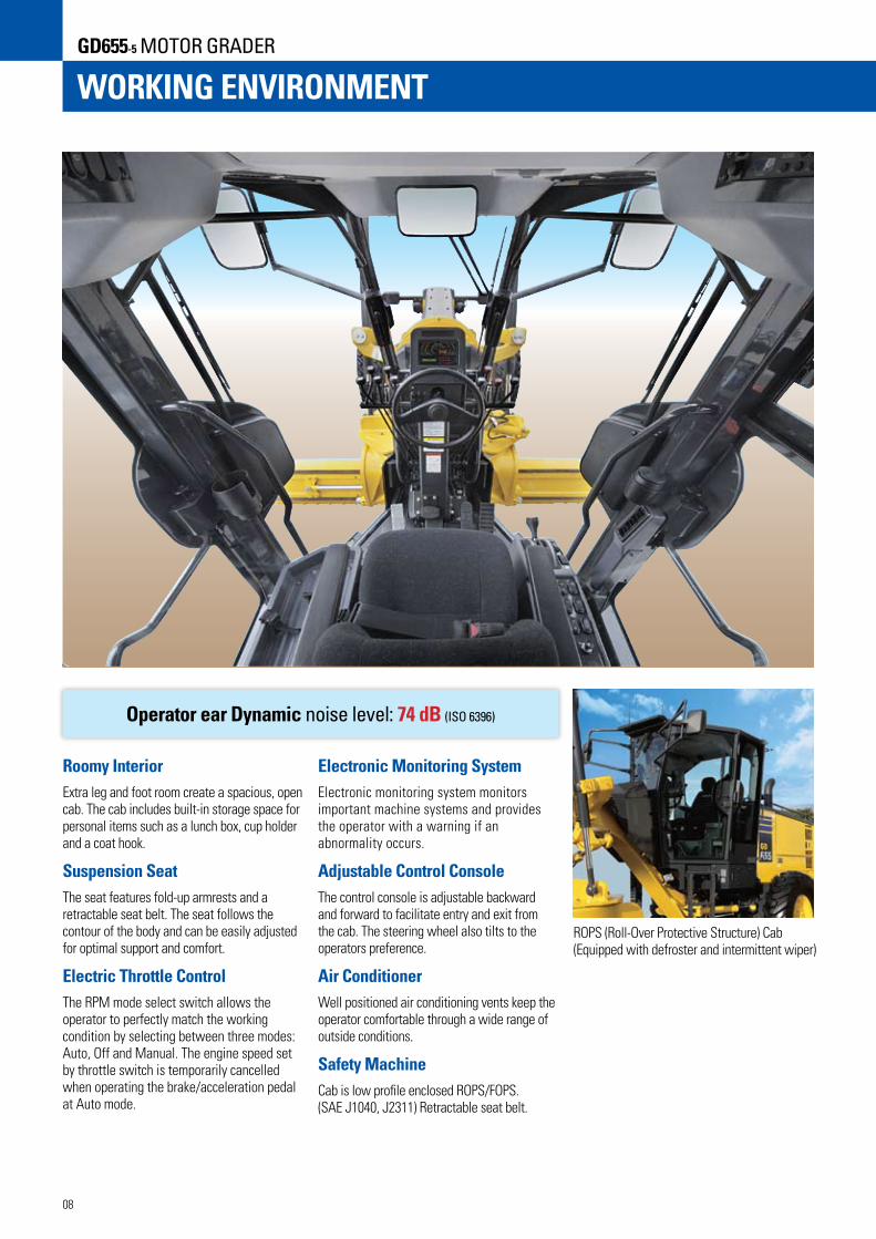
WORKING ENVIRONMENT
Roomy InteriorExtra leg and foot room create a spacious, open cab. The cab includes built-in storage space for personal items such as a lunch box, cup holder and a coat hook.
Suspension SeatThe seat features fold-up armrests and a retractable seat belt. The seat follows the contour of the body and can be easily adjusted for optimal support and comfort.
Electric Throttle ControlThe RPM mode select switch allows the operator to perfectly match the working condition by selecting between three modes: Auto, Off and Manual. The engine speed set by throttle switch is temporarily cancelled when operating the brake/acceleration pedal at Auto mode.
Operator ear Dynamic noise level: 74 dB (ISO 6396)
Electronic Monitoring SystemElectronic monitoring system monitors important machine systems and provides the operator with a warning if an abnormality occurs.
Adjustable Control ConsoleThe control console is adjustable backward and forward to facilitate entry and exit from the cab. The steering wheel also tilts to the operators preference.
Air ConditionerWell positioned air conditioning vents keep the operator comfortable through a wide range of outside conditions.
Safety MachineCab is low profile enclosed ROPS/FOPS. (SAE J1040, J2311) Retractable seat belt.
ROPS (Roll-Over Protective Structure) Cab (Equipped with defroster and intermittent wiper)
08
GD655-5 MOTOR GRADER

Excellent Visibility from cab.Excellent VisibilityExceptional visibility by hexangular cab with front Y shape pillar and rear layout side pillar (patent pending) helps increase operator confidence and productivity in all grader applications. The well positioned blade linkage provides an unobstructed view of the moldboard and front tyers. The tapered engine hood provides good visibility to the rear of the machine, especially the rear ripper.
09
MOTOR GRADER
SPECIFICATIONS
ENGINE Model . . . . . . . . . . . . . . . . . . . . . KOMATSU SAA6D107E-1 Type . . . . . . . . . . . . . . . Water-cooled, 4 cycle, direct injection Aspiration . . . . . . . . . . . .Turbocharged and air to air aftercooled Number of cylinders . . . . . . . . . . . . . . . . . . . . . . . . . . . 6 Bore . . . . . . . . . . . . . . . . . . . . . . . . . . .107 mm 4.21” Stroke . . . . . . . . . . . . . . . . . . . . . . . . . . . 124 mm 4.88” Piston displacement . . . . . . . . . . . . . . . . . . . 6.69 ltr 408 in3
Gross horsepower (Manual mode) P-mode Gear 1-3 . . . . . . . . . . . . . . . . . . 136 kW 183 HP@2000 rpm Gear 4-6 . . . . . . . . . . . . . . . . . . 151 kW 203 HP@2000 rpm Gear 7-8 . . . . . . . . . . . . . . . . . . .165 kW 221 HP@2100 rpm E-mode Gear 1-3 . . . . . . . . . . . . . . . . . . 110 kW 148 HP@2000 rpm Gear 4-6 . . . . . . . . . . . . . . . . . . 136 kW 183 HP@2000 rpm Gear 7-8 . . . . . . . . . . . . . . . . . . 151 kW 203 HP@2000 rpm Net flywheel horsepower* (Manual mode) P-mode Gear 1-3 . . . . . . . . . . . . . . . . . . 134 kW 180 HP@2000 rpm Gear 4-6 . . . . . . . . . . . . . . . . . . 149 kW 200 HP@2000 rpm Gear 7-8 . . . . . . . . . . . . . . . . . . . 163 kW 218 HP@2100 rpm E-mode Gear 1-3 . . . . . . . . . . . . . . . . . . 108 kW 145 HP@2000 rpm Gear 4-6 . . . . . . . . . . . . . . . . . . .134 kW 180 HP@2000 rpm Gear 7-8 . . . . . . . . . . . . . . . . . . .149 kW 203 HP@2000 rpm Max. torque . . . . . . . . . . 941 Nm 96.0 kg.m 694 Ib.ft@1450 rpm Torque rise . . . . . . . . . . . . . . . . . . . . . . . . . . . . . . 31% Fan speed . . . . . . . . . . . . . . . . . . . . . . . Max. 1500 rpm Air cleaner . . . . . . . . . . . . . . . . . . . . . . . .2-stage, dry-type Electrical . . . . . . . . . . . . . . . . . 24 volt with 90 amp alternator Battery . . . . . . . . . . . 2, low maintenance plus, 12 volt, 1146 cca
* Net flywheel HP output for standard (SAE J1349) including air cleaner, alternator (not charging), water pump, lubricating oil, fuel pump, muffler and fan running at minimum speed.
TRANSMISSION & TORQUE CONVERTER Full power shift transmission with integral free wheeling stator torque converter and lock-up.
Speeds (at rated engine speed)
TANDEM DRIVE Oscillating welded box section . . . . . . . 520 mm x 202 mm 1’8” x 8” Side wall thickness: Inner . . . . . . . . . . . . . . . . . . . 22 mm 0.87” Outer . . . . . . . . . . . . . . . . . . . . . . . . . . . . . . 19 mm 0.75” Wheel axle spacing . . . . . . . . . . . . . . . . . . . . . .1525 mm 5’0” Tandem oscillation . . . . . . . . . . . . . . . . 11° forward, 13 ° reverse
FRONT AXLE Type . . . . . . . . . . . . . Solid bar construction welded steel sections Ground clearance at pivot . . . . . . . . . . . . . . . . . . . 620 mm 2’0” Wheel lean angle, right or left . . . . . . . . . . . . . . . . . . . . . 20 ° Oscillation, total . . . . . . . . . . . . . . . . . . . . . . . . . . . . . 32 °
REAR AXLE Alloy steel, heat treated, full floating axle with lock/unlock differential.
WHEELS, FRONT & REAR Bearings . . . . . . . . . . . . . . . . . . . . . . . . . . . . Tapered roller Tyres . . . . . . . . . . . . . . . . . . . . . . . . . . . . . .17.5 - 25 radial Tyre rims (demountable) . . . . . . . . . . . . . . . . 14” three piece rims
STEERING Hydraulic power steering providing stopped engine steering complies with SAE J23 and J1151.
Minimum turning radius . . . . . . . . . . . . . . . . . . . . 7.4 m 24’3” Maximum steering range, right or left . . . . . . . . . . . . . . . . . 49 ° Articulation . . . . . . . . . . . . . . . . . . . . . . . . . . . . . . . . 25 °
BRAKES Service brake . . . .Foot operated, oil disc brakes, hydraulically actuated on four tandem wheels, 13691 cm2 2122 in2 total braking surface Parking brake . . . .Manually actuated, spring applied, hydraulically released caliper with transmission interlock
FRAME Front Frame Structure - Height . . . . . . . . . . . . . . . .300 mm 11.8” Front Frame Structure - Width . . . . . . . . . . . . . . . .300 mm 11.8” Front Frame Structure - Thickness . . . . . . . . . . . . . .14 mm 0.47”
Gear Forward Reverse
1st 3.4 km/h 2.1 mph 4.5 km/h 2.8 mph
2nd 5.0 km/h 3.1 mph 9.2 km/h 5.7 mph
3rd 7.0 km/h 4.3 mph 20.3 km/h 12.6 mph
4th 10.2 km/h 6.3 mph 40.3 km/h 25.0 mph
5th 15.4 km/h 9.6 mph
6th 22.3 km/h 13.9 mph
7th 30.6 km/h 19.0 mph
8th 44.3 km/h 27.5 mph
10
GD655-5 MOTOR GRADER
DRAWBAR A-shaped, u-section press formed and welded construction for maximum strength with a replaceable drawbar ball.
Drawbar frame . . . . . . . . . . . . . . . . . . . 210 x 25 mm 8.3” x 1”
CIRCLE Single piece rolled ring forging. Six circle support shoes with replaceable wear surface. Circle teeth hardened on front 180° of circle.
Diameter (outside) . . . . . . . . . . . . . . . . . . . . . . 1530 mm 5’0” Circle reversing control hydraulic rotation . . . . . . . . . . . . . . . 360 °
MOLDBOARD Hydraulic power shift fabricated from high carbon steel. Includes replaceable metal inserts, cutting edge and end bits. Cutting edge and end bits are hardened.
Dimensions . . . . . . . . . . . 4320 x 645 x 25 mm 14’2” x 2’1” x 0.98” Arc radius . . . . . . . . . . . . . . . . . . . . . . . . . . . . 329 mm 1’1” Cutting Edge . . . . . . . . . . . . . . . . . . . . 152 x 16 mm 6” x 0.63”
BLADE RANGE Circle center shift: Right . . . . . . . . . . . . . . . . . . . . . . . . . . . .. . 590 mm 1’11” Left . . . . . . . . . . . . . . . . . . . . . . . . . . . . . . 590 mm 1’11” Moldboard side shift: Right . . . . . . . . . . . . . . . . . . . . . . . . . . . . . . 820 mm 2’8” Left . . . . . . . . . . . . . . . . . . . . . . . . . . . . . . . 820 mm 2’8” Maximum shoulder reach outside rear tyres (frame straight): Right . . . . . . . . . . . . . . . . . . . . . . . . . . . . . 2000 mm 6’7” Left . . . . . . . . . . . . . . . . . . . . . . . . . . . . . 2000 mm 6’7” Maximum lift above ground . . . . . . . . . . . . . . . . . 480 mm 1’7” Maximum cutting depth . . . . . . . . . . . . . . . . . . . . 615 mm 2’0” Maximum blade angle, right or left . . . . . . . . . . . . . . . . . . . 90 ° Blade tip angle . . . . . . . . . . . . . . . . . 40 ° forward, 5 ° backward
HYDRAULICS Load-sending closed center hydraulics with variable displacement piston pump. Short stroke/low effort direct acting control valves with preselected maximum flow setting to each function. Double acting anti-drift check valves on blade lift, tip, circle shift, articulation and leaning wheels.
Output . . . . . . . . . . . . . .200 ltr/min 52.8 U.S.gal/min@ 2000 rpm Standby pressure . . . . . . . . . . . . . . . . 3.4 MPa 35 kg/cm2 500 psi Maximum system pressure . . . . . . . .20.6 MPa 210 kg/cm2 3,000 psi
INSTRUMENT Electronic monitoring system with diagnostics: Gauges: Articulation, engine coolant temperature, fuel level, speed meter, T/M shift indicator, engine tachometer, torque converter oil temperature. Warning lights/indicator: Battery charge, brake oil pressure, blade float, brake oil pressure, inching temperature, directional indicator, engine oil pressure, hydraulic oil temperature, heater signal, lift arm lock, parking brake, differential lock, torque converter oil temperature, eco, P mode, fan reverse, rpm set, high beam, working lights
CAPACITIES (refilling) Fuel tank . . . . . . . . . . . . . . . . . . . . . . . . 416 ltr 109.9 U.S gal Cooling system . . . . . . . . . . . . . . . . . . . . . 24.9 ltr 6.6 U.S gal Crank case . . . . . . . . . . . . . . . . . . . . . . . . 23.1 ltr 6.1 U.S gal Transmission . . . . . . . . . . . . . . . . . . . . . . . 45 ltr 11.9 U.S gal Final Drive . . . . . . . . . . . . . . . . . . . . . . . . . 17 ltr 4.5 U.S gal Tandem Housing (each) . . . . . . . . . . . . . . . . . 57 ltr 15.1 U.S gal Hydraulic system . . . . . . . . . . . . . . . . . . . . . 69 ltr 18.2 U.S gal Circle reverse housing . . . . . . . . . . . . . . . . . . . 7 ltr 1.8 U.S gal
OPERATING WEIGHT (approx) Includes lubricants, coolant, full fuel tank Total . . . . . . . . . . . . . . . . . . . . . . . . . . .18520 kg 40, 744 Ib On rear wheels . . . . . . . . . . . . . . . . . . . . . 13150 kg 28, 930 Ib On front wheels . . . . . . . . . . . . . . . . . . . . . 5370 kg 11, 814 Ib
11
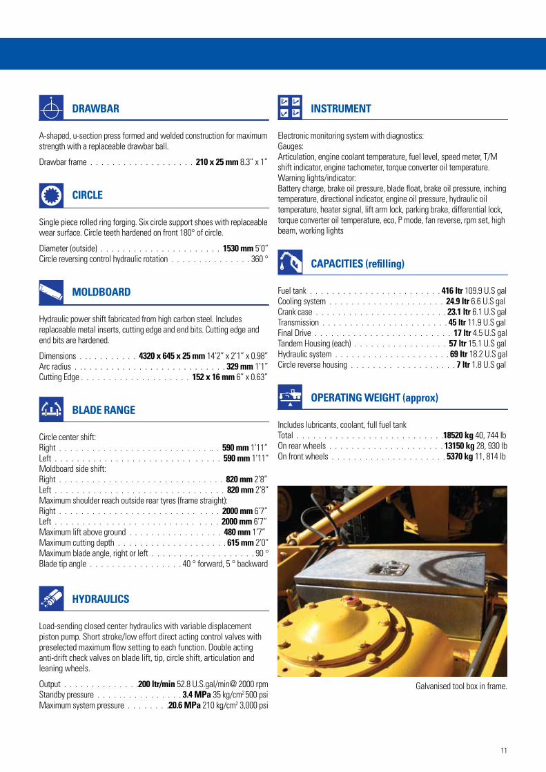
Galvanised tool box in frame.
I
J
K
L*
F
G* D
E
H*
A
C B*
N
M*
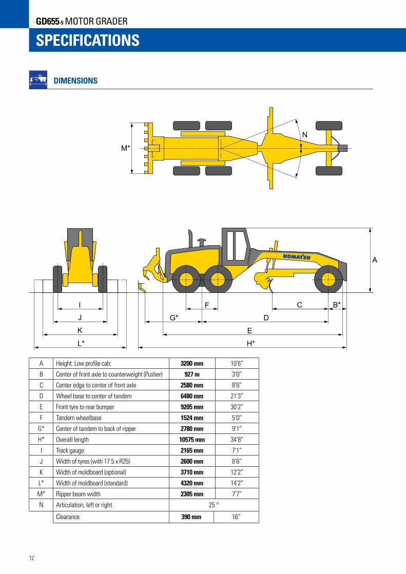
DIMENSIONS
A Height: Low profile cab: 3200 mm 10’6”
B Center of front axle to counterweight (Pusher) 927 m 3’0”
C Center edge to center of front axle 2580 mm 8’6”
D Wheel base to center of tandem 6480 mm 21’3”
E Front tyre to rear bumper 9205 mm 30’2”
F Tandem wheelbase 1524 mm 5’0”
G* Center of tandem to back of ripper 2780 mm 9’1”
H* Overall length 10575 mm 34’8”
I Track gauge 2165 mm 7’1”
J Width of tyres (with 17.5 x R25) 2600 mm 8’6”
K Width of moldboard (optional) 3710 mm 12’2”
L* Width of moldboard (standard) 4320 mm 14’2”
M* Ripper beam width 2305 mm 7’7”
N Articulation, left or right 25 °
Clearance 390 mm 16”
12
SPECIFICATIONSGD655-5 MOTOR GRADER
13
STANDARD EQUIPMENT
Engine and Related Items » Double element air cleaner and dust indicator» Engine: Komatsu SAA6D107E-1, EPA Tier-3 certified, turbocharged and
air-to-air aftercooled, standard VHPC, 145-218 net horsepower
» Fuel line pre-filter» Hood-sides for engine compartment» Air intake extension» Pre-cleaner, Turbo II Electrical Systems » Reverse alarm » Alternator, 90 amp, 24 V» Battery, extreme duty, 1146 cca each» Dome light cab» Horn, electric» Lights: back-up, stop, tail, directional, headlights (2) halogen type,
front bar mounted» Work lamps: front (4), rear (2)» Cab mount work lamps (4) » Warning light, amber coloured rotating beacon, cab roof mounted (2)» Speedometer» Indicators: parking brake, differential lock, blade float, lift arm lock,
high beam, eco, engine P mode, cooling fan reverse, rpm set, engine oil pressure, battery charge, brake oil pressure, differential oil temperature
Operator Environment » Cab: low profile enclosed ROPS/FOPS (SAE J1040, J2311) with safety
tinted glass windows with wiper and washer» Air conditioner (R134a) » Console, adjustable with instrumental panel
monitoring system» Mirrors: interior cab, right and left exterior mirrors» Seat, deluxe adjustable cloth with retractable seat belt» Sound Suppression, cab and floor mat» Wipers, front, doors and rear» 12V (10A) power port
Power Train » Dual mode Transmission (8F-4R) power shift, direct drive and torque
converter with auto shift» Axle, rear full floating, planetary type» Service brakes, fully hydraulic wet disc» Brake, parking, spring applied, hydraulic release, disc type» Differential, lock/unlock Work Equipment and Hydraulics » Circle, drawbar mounted, 360° rotation hydraulic blade lift and circle
side shift» Circle slip clutch» Hydraulic system, closed center, load sensing» Accumulators, anti-shock for blade lift» Moldboard: 4320 mm x 645 mm x 25 mm 14’2” x 2’1” x 0.98”,
hydraulic blade side shift and hydraulic tilt with anti-drift check valves. Maximum moldboard angle position 90° right and left.
» Steering, full hydraulic with tilt steering wheel plus leaning front wheels and frame articulation w/anti-drift check valves
» 10 section hydraulic control valve» Blade lift float detent style, LH and RH» Ripper, assembly, rear mounted» Ripper shanks and points (3)» Scarifier, shanks and points (9) Other Standard Equipment » Painting, Komatsu standard colour scheme» Steps and handrails, rear, right and left side» Vandalism protection includes lockable access to fuel tank, battery
cover, and engine side covers» Tool box with lock on tandem» Large galvanised tool box in ‘Y’ frame» Fuel tank, ground level access» Battery disconnect switch» Push plate» KOMTRAX» AM/FM radio» Hydraulic driven air compressor with tank» Tyres: 17.5-25 radial on 3 piece 13” rims
OPTIONAL EQUIPMENT
» Moldboard: 3710 mm x 645 mm x 22 mm 12’2” x 2’1” x 0.86» Front blade » Air suspension seat » Tyres: 14.00-24 radial on 3 piece 10” rims (width 2,490 mm; deduct 100 kg for 6 tyres and rims)» Spare cutting edge corner » Spare scarifier carrier» Spare tyre carrier
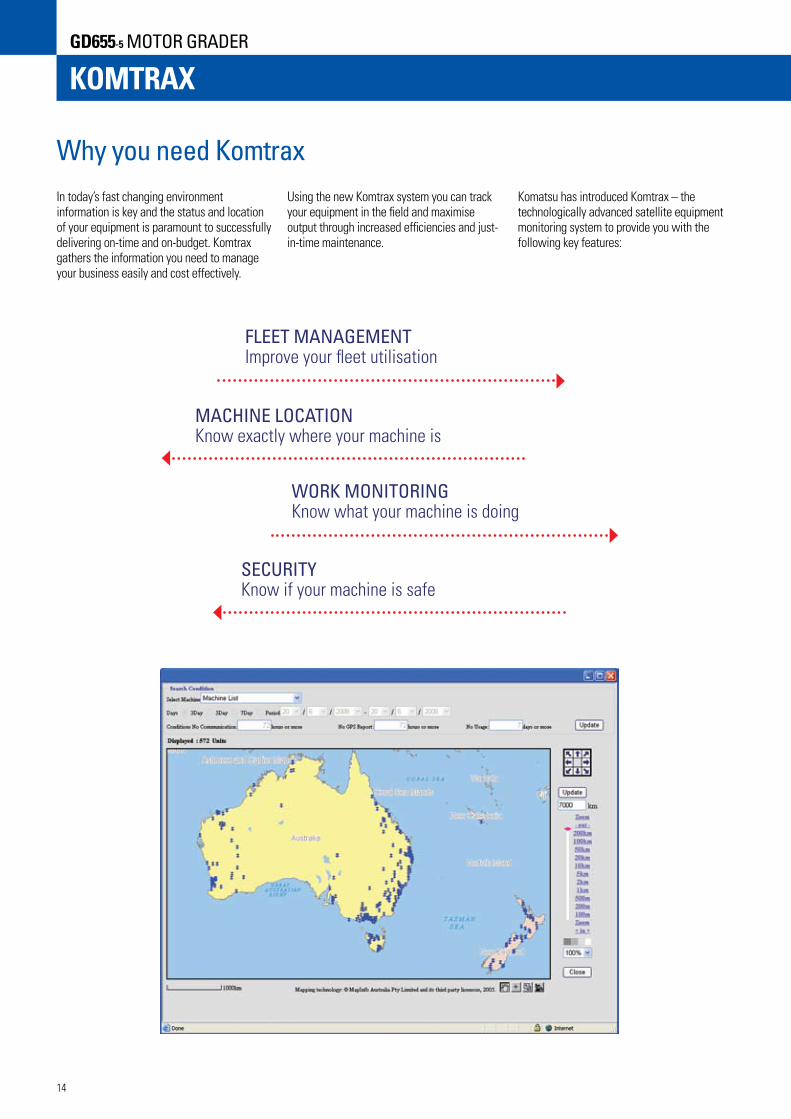
Why you need KomtraxIn today’s fast changing environment information is key and the status and location of your equipment is paramount to successfully delivering on-time and on-budget. Komtrax gathers the information you need to manage your business easily and cost effectively.
FLEET MANAGEMENT Improve your fleet utilisation
MACHINE LOCATION Know exactly where your machine is
WORK MONITORING Know what your machine is doing
SECURITY Know if your machine is safe
Using the new Komtrax system you can track your equipment in the field and maximise output through increased efficiencies and just-in-time maintenance.
Komatsu has introduced Komtrax – the technologically advanced satellite equipment monitoring system to provide you with the following key features:
KOMTRAXGD655-5 MOTOR GRADER
14

MOTOR GRADER
How does Komtrax work?Komtrax is a system which allows you to view all the information about your Komatsu equipment directly on your computer.
This information is downloaded via satellite and you can view what the operator sees on his monitor panel and the type of work the machine is doing.
The Komtrax information format is universal and allows you to see your complete Komtrax equipped fleet on one system.
Komtrax can be easily accessed through a generic web browser.
1. GPS satellite provides position information to your equipment in the field.
2. The Komtrax unit in your machine gathers engine data and position, and sends this information to the satellite.
3. The communication satellite transmits information to the Komtrax data centre.
5. You can access the information gathered from your machine directly via the Internet from the Komtrax data centre.
4. The Komtrax data centre stores and distributes the information throughout the machine life.
15