Embed Size (px)
Citation preview

GCSE Electronic Products
Revision Flashcards

555 timer
•8 pin Integrated Circuit (I.C.)•Analog•can be used as an astable or monostable•Low cost

Monostable(the egg timer)
•Has a single (mono) stable state• when it is timing
•The output is normally off
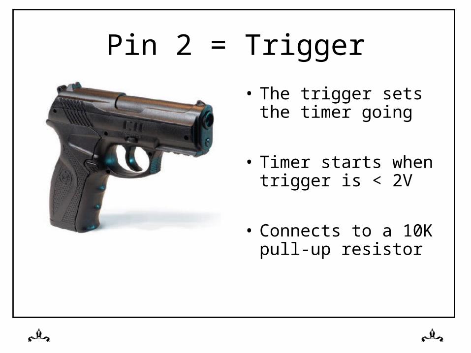
Pin 2 = Trigger
• The trigger sets the timer going
• Timer starts when trigger is < 2V
• Connects to a 10K pull-up resistor

Pull-up resistor
• Pulls the voltage up on a wire to supply voltage
• Makes a “nice” logic high

Pull Down Resistor
• Pulls the voltage on a wire down to 0V
• Gives a “nice” logic 0

Pin 6 = Threshold• Detects when the bucket
(capacitor) is 2/3rds full
• The capacitor fills up through a resistor
• Time to fill to 2/3rds full = Resistor Value x Capacitor Value (T = RC)

Pin 7 = discharge
• Empties the bucket (capacitor)

Astable(The “flasher” circuit)
• Has no stable states
• Keeps on flashing forever
• Number of flashes per second = frequency
• Automatically triggers

The Op-Amp• - input = inverting
• + input = non-inverting
• used as an inverting amplifier or a comparator
• An analog device
• A 741 I.C. is an example of an op-amp

Inverting
• Means it turns the signal upside down

Gain• The ability of a device
to make a signal bigger
• Op-amps have huge “open loop” gain
• Transistors also have gain

Feedback• Gain can be reduced by
using feedback
• Some of the output is taken away and added to the input
• We use resistors to do this

Comparator(Which input is bigger)
• If “+” is bigger than “-” we get a logic 1
• If “+” is smaller than “-” then we get a logic 0
• A simple analog to digital converter
+ -

Ohms Law
• As resistance increases, current decreases
• As resistance increases, voltage increases

Sources of power

P.I.C.(Peripheral Interface Controller)
• Digital• A mini-computer in a
single Integrated Circuit• Programmable using
flowcharts• Can be programmed many
times• Remembers program even
when the power is off

Diode(A one way valve)
• Current flows from anode to cathode
• Prevents current flowing the wrong way
• Protects circuits if the power supply is connected up wrong

Transducer(A device for converting energy
from one form to another• Motor – converts electrical
energy to kinetic energy• LED – converts electrical
energy to light• Microphone - converts
sound energy to electrical energy

Transducer Drivers(Things that provide power to output transducers)
• Bipolar Transistors• FET’s• Darlington Pairs

Tolerance
• The amount of “spread” in a components value
• 100Ω and 10% tolerance gives a spread between 90Ω and 110Ω

E12 Series
• The values that 10% tolerance resistors are made in to avoid value overlap
• 10, 12, 15, 18, 22 etc• 100, 120, 150, 180 etc

Polymorph – Smart Material
• Used to rapidly model complex shapes
• Granules put in hot water turn solid and can be immediately shaped
+

clock
• A digital signal that has a regular repeating on/off pattern
• Often generated by an astable
• Used by PICs & counters

HIPS
• Plastic material used for vacuum forming
• Available in different colours
• Used to make complex 3d shapes
• Boxes must have angled sides to get the mold out

Breadboard
• Used to model circuit using real component
• No soldering• Easy to change
connections• Components can be re-
used

CAD(Computer Aided Design)
• Testing by simulation
• Links to CAM (Computer Aided Manufacture)
• Easy to share designs with others and keep track of changes
• Making changes is a quick & easy process

Latch Circuit• Can be made using a
thyristor
• Can be made with NOR or NAND gates
• When activated, stays activated until reset– Remembers that it has
been activated

Thyristor• Used in latch circuits
• A pulse on the gate causes current to flow from Anode to Cathode until reset
• Reset by making the Anode voltage the same as the Cathode

Potential Divider
• A circuit for dividing voltages
• Voltage splits based upon the ratio of two resistors

Schmitt Trigger
• A type of circuit used to remove switch bounce

Thermistor• Device for measuring
temperature
• As temperature increases, resistance decreases
• Often used as part of a potential divider

LDR(Light Dependent Resistor)
• As light increases, resistance decreases
• Often used as part of a potential divider

Multimeter
• Device for measuring:– Current– Voltage– Resistance
• Has red & black probes

The 3 R’s(Helping The Environment)
• Reducecut the materials you use
• Reusemake use of existing products
• Recyclestop the product going to landfill when obsolete

Resistors• Measured in Ohms
(Ω)
• Used to reduce current
• Colour bands indicate the value

Integrated Circuits
• Pin 1 is to the left of the notch
• Lots of components on a single piece of silicon
• Examples are:– PICS– 555’s– 741’s

Switch Bounce
• A problem with mechanical PTM & PTB switches
• One press of the switch generates more than one pulse

AND Gate
• Both inputs must be at logic 1 to get a logic 1 out
• A = 1 AND B= 1

OR GATE
• Either one of the two inputs can be at logic 1 to create a 1 on the output
• A=1 OR B=1

Relay
• A device that allows one circuit to turn on another circuit that works at a different voltage
• Uses electro-magnets

Variable Resistor
• Used for– volume controls
– Changing astable frequencies
– Changing mono-stable time periods

4017• Output 0 is on• When a clock pulse is
received:– Output0 turns off– Output1 turns on
• On next clock pulse– Output1 turns off– Output2 turns on

SPDT SWITCH(Single Pole Double Throw)
• One circuit• Two positions• Three pins• Two different sets of
components can be switched into one circuit

Life Cycle Analysis
• What happens to a product when it is disposed of:
– Reused in a new product
– Recycled– Goes to landfill

Multipliers
1,000,000,000 = 1G = 1 x 10⁹
1,000,000 = 1M = 1 x 10⁶
1,000 = 1K = 1 x 10³
1 = 1 = 1 x 101
0.001 = 1m = 1 x 10⁻³
0.000,001 = 1µ = 1 x 10⁻⁶
0.000,000,001 = 1n = 1 x 10⁻⁹
0.000,000,000,001 = 1p = 1 x 10-12

Units of MeasureMeasurement Unit Symbol
Resistance Ohms Ω
Capacitance Farads F
Voltage Volts V
Current Amps I
Power Watts W
Time Seconds S


![UNIVERSITY OF CALCUTTA · Circuit, Frequency Response, Input and Output Impedance, Current and Voltage ... Astable and Monostable Multivibrator Circuits. [2 Lectures] Number System](https://img.pdfslide.us/doc/110x75/5e78cc61be82a533263558a8/university-of-calcutta-circuit-frequency-response-input-and-output-impedance.jpg)