Embed Size (px)
Citation preview
© G
uldm
ann
GB
/US
-09/
2012
• #
553
211_
2
GB/US . . . . .Free-standing .rail .system, .adjustable .
Vers . .2 .00
2
© G
uldm
ann
GB
/US
-09/
2012
• #
553
211_
2
© G
uldm
ann
GB
/US
-09/
2012
• #
553
211_
2
© G
uldm
ann
GB
/US
-09/
2012
• #
553
211_
2
© G
uldm
ann
GB
/US
-09/
2012
• #
553
211_
2
. Free-standing .rail .systems, .adjustable
Item .no:553000
1 .00 . . . . . . . . . .Purpose .and .use . . . . . . . . . . . . . . . . . . . . . . . . . . . . . . . . . . . . . . . . . . . . . . . 31.01 . . . . . . . . . Manufacturer . . . . . . . . . . . . . . . . . . . . . . . . . . . . . . . . . . . . . . . . . . . . . . . . . . 31.02 . . . . . . . . . Intended use and description. . . . . . . . . . . . . . . . . . . . . . . . . . . . . . . . . . . . . . 31.03 . . . . . . . . . Important precautions . . . . . . . . . . . . . . . . . . . . . . . . . . . . . . . . . . . . . . . . . . . 31.04 . . . . . . . . . Hoists made by other manufacturers . . . . . . . . . . . . . . . . . . . . . . . . . . . . . . . . 31.05 . . . . . . . . . Unpacking . . . . . . . . . . . . . . . . . . . . . . . . . . . . . . . . . . . . . . . . . . . . . . . . . . . . 41.06 . . . . . . . . . Setting up the system . . . . . . . . . . . . . . . . . . . . . . . . . . . . . . . . . . . . . . . . . . . 5
2 .00 . . . . . . . . . .Description .of .functions . . . . . . . . . . . . . . . . . . . . . . . . . . . . . . . . . . . . . . . . . 92.01 . . . . . . . . . Operation . . . . . . . . . . . . . . . . . . . . . . . . . . . . . . . . . . . . . . . . . . . . . . . . . . . . . 92.02 . . . . . . . . . Length and height adjustment . . . . . . . . . . . . . . . . . . . . . . . . . . . . . . . . . . . . 9
3 .00 . . . . . . . . . .Demounting .and .transportation . . . . . . . . . . . . . . . . . . . . . . . . . . . . . . . . . . . 93.01 . . . . . . . . . Demounting the system . . . . . . . . . . . . . . . . . . . . . . . . . . . . . . . . . . . . . . . . . . 93.02 . . . . . . . . . Transporting the system . . . . . . . . . . . . . . . . . . . . . . . . . . . . . . . . . . . . . . . . 10
4 .00 . . . . . . . . . .Maintenance .and .storage . . . . . . . . . . . . . . . . . . . . . . . . . . . . . . . . . . . . . . . 104.01 . . . . . . . . . Cleaning . . . . . . . . . . . . . . . . . . . . . . . . . . . . . . . . . . . . . . . . . . . . . . . . . . . . . 104.02 . . . . . . . . . Storage . . . . . . . . . . . . . . . . . . . . . . . . . . . . . . . . . . . . . . . . . . . . . . . . . . . . . 104.03 . . . . . . . . . Maintenance . . . . . . . . . . . . . . . . . . . . . . . . . . . . . . . . . . . . . . . . . . . . . . . . . 10
5 .00 . . . . . . . . . .Service .and .life .span . . . . . . . . . . . . . . . . . . . . . . . . . . . . . . . . . . . . . . . . . . . 105.01 . . . . . . . . . Life span . . . . . . . . . . . . . . . . . . . . . . . . . . . . . . . . . . . . . . . . . . . . . . . . . . . . 105.02 . . . . . . . . . Troubleshooting . . . . . . . . . . . . . . . . . . . . . . . . . . . . . . . . . . . . . . . . . . . . . . . 11
6 .00 . . . . . . . . . . Technical .specifications . . . . . . . . . . . . . . . . . . . . . . . . . . . . . . . . . . . . . . . . 11
7 .00 . . . . . . . . . .EC-Declaration .of .conformity . . . . . . . . . . . . . . . . . . . . . . . . . . . . . . . . . . . . 11
. . . . . . . . . . . . . . . . . . . . . . . . .USA .and .countries .outside .the .EU . . . . . . . . . . . . . . . . . . . . . . . . . . . . . . . 12A. . . . . . . . . . . .Users guide . . . . . . . . . . . . . . . . . . . . . . . . . . . . . . . . . . . . . . . . . . . . . . . . . . 12B. . . . . . . . . . .WARRANTY . . . . . . . . . . . . . . . . . . . . . . . . . . . . . . . . . . . . . . . . . . . . . . . . . . 12
3
© G
uldm
ann
GB
/US
-09/
2012
• #
553
211_
2
© G
uldm
ann
GB
/US
-09/
2012
• #
553
211_
2
© G
uldm
ann
GB
/US
-09/
2012
• #
553
211_
2
© G
uldm
ann
GB
/US
-09/
2012
• #
553
211_
2
1 .00 . Purpose .and .use
1 .01 . ManufacturerV. Guldmann A/SGraham Bells Vej 21-23A DK-8200 Aarhus NTel. + 45 8741 3100Fax + 45 8741 3131
1 .02 . Intended .use .and .descriptionThe free-standing rail system together with the GH1 hoist shall be used for transferring an elderly or a disabled person; e.g. in private homes.
The free-standing rail system is a portable rail system which can be set up practically anywhere and requires no mounting on walls, ceiling or floors. The free-standing rail system is length and height adjustable.
1 .03 . Important .precautionsRead the entire user manual prior to setting up and starting to use the free-standing rail system.
The free-standing system can be set up and taken down by one person only.
The maximum load of 250 kg must not be exceeded.
In case of damage to the free-standing rail system, the operation of it should be discontinued immediately.
The free-standing rail system should be set up on a plane surface.
The end stops have to be properly installed and locked with spring pins, and the 2 yellow thumb screws on the top brackets have to be properly tightened before the system must be used.
The free-standing rail system must not be used for any other purpose than that stated in this user manual; that is, neither as a playground or a swing device.
1 .04 . Hoists .made .by .other .manufacturersGuldmann is not liable for defects or accidents caused by the application of hoists/lifting modules made by other manufacturers.
4
c
�
�
�
���������������������������������������������
����������
d
a
b
© G
uldm
ann
GB
/US
-09/
2012
• #
553
211_
2
© G
uldm
ann
GB
/US
-09/
2012
• #
553
211_
2
© G
uldm
ann
GB
/US
-09/
2012
• #
553
211_
2
© G
uldm
ann
GB
/US
-09/
2012
• #
553
211_
2
1 .05 . Unpacking
Inspection .before .unpackingIf the packaging is damaged upon receipt, the components of the free-standing rail system should be carefully checked for noticeable imperfections, defects or flaws.
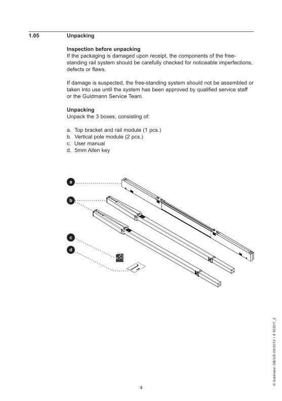
If damage is suspected, the free-standing system should not be assembled or taken into use until the system has been approved by qualified service staff or the Guldmann Service Team. UnpackingUnpack the 3 boxes, consisting of:
a. Top bracket and rail module (1 pcs.) b. Vertical pole module (2 pcs.)c. User manuald. 5mm Allen key
5
Fig . .1
Fig . .3
Fig . .2
Fig . .4
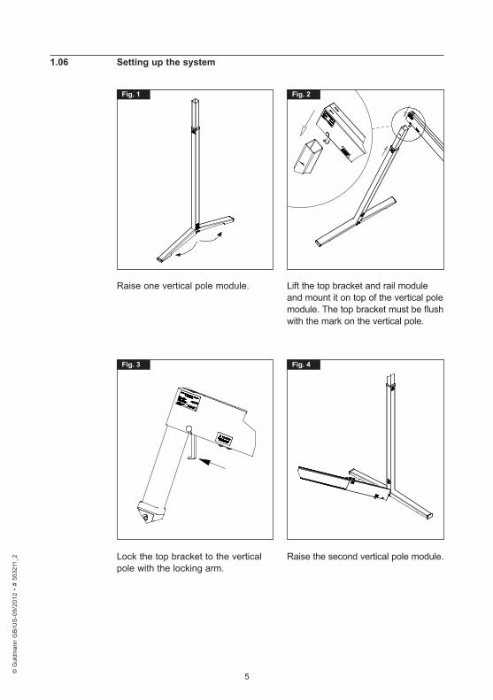
Raise one vertical pole module. Lift the top bracket and rail module and mount it on top of the vertical pole module. The top bracket must be flush with the mark on the vertical pole.
Lock the top bracket to the vertical pole with the locking arm.
Raise the second vertical pole module.
© G
uldm
ann
GB
/US
-09/
2012
• #
553
211_
2
© G
uldm
ann
GB
/US
-09/
2012
• #
553
211_
2
© G
uldm
ann
GB
/US
-09/
2012
• #
553
211_
2
© G
uldm
ann
GB
/US
-09/
2012
• #
553
211_
2
1 .06 . Setting .up .the .system
6
Fig . .5
Fig . .7
Fig . .6
Fig . .8
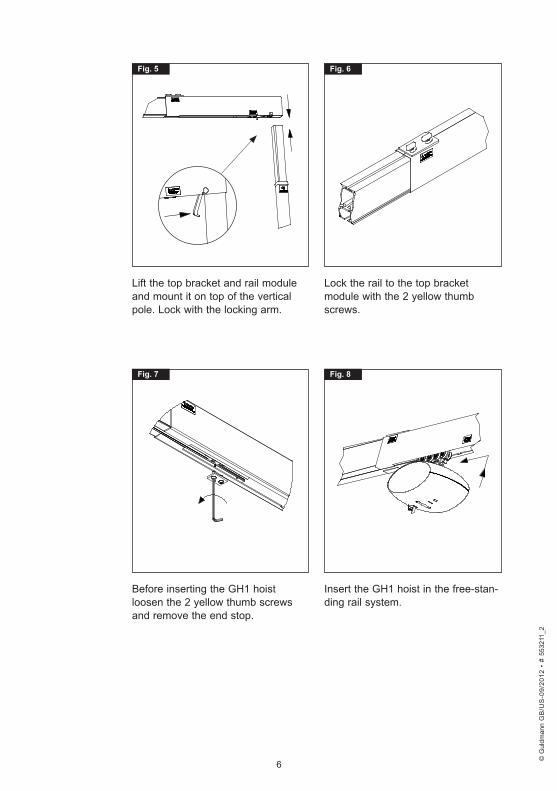
Lift the top bracket and rail module and mount it on top of the vertical pole. Lock with the locking arm.
Lock the rail to the top bracket module with the 2 yellow thumb screws.
Before inserting the GH1 hoist loosen the 2 yellow thumb screws and remove the end stop.
Insert the GH1 hoist in the free-stan-ding rail system.
© G
uldm
ann
GB
/US
-09/
2012
• #
553
211_
2
© G
uldm
ann
GB
/US
-09/
2012
• #
553
211_
2
© G
uldm
ann
GB
/US
-09/
2012
• #
553
211_
2
© G
uldm
ann
GB
/US
-09/
2012
• #
553
211_
2
7
Fig . .9
Fig . .11
Fig . .10
Fig . .12
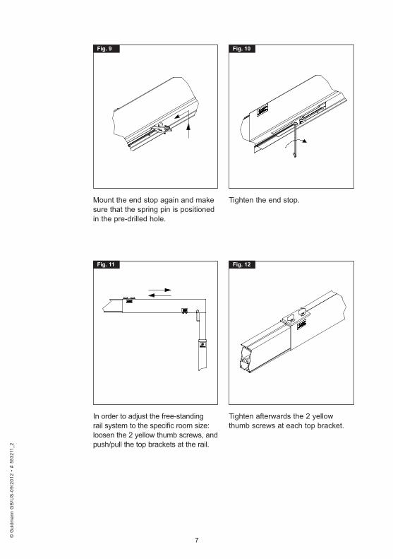
Mount the end stop again and make sure that the spring pin is positioned in the pre-drilled hole.
Tighten the end stop.
In order to adjust the free-standing rail system to the specific room size: loosen the 2 yellow thumb screws, and push/pull the top brackets at the rail.
Tighten afterwards the 2 yellow thumb screws at each top bracket.
© G
uldm
ann
GB
/US
-09/
2012
• #
553
211_
2
© G
uldm
ann
GB
/US
-09/
2012
• #
553
211_
2
© G
uldm
ann
GB
/US
-09/
2012
• #
553
211_
2
© G
uldm
ann
GB
/US
-09/
2012
• #
553
211_
2
8
Fig . .13
Fig . .15
Fig . .14
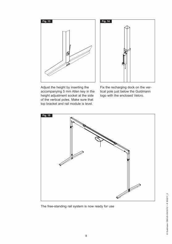
Adjust the height by inserting the accompanying 5 mm Allen key in the height adjustment socket at the side of the vertical poles. Make sure that top bracket and rail module is level.
Fix the recharging dock on the ver-tical pole just below the Guldmann logo with the enclosed Velcro.
The free-standing rail system is now ready for use
© G
uldm
ann
GB
/US
-09/
2012
• #
553
211_
2
© G
uldm
ann
GB
/US
-09/
2012
• #
553
211_
2
© G
uldm
ann
GB
/US
-09/
2012
• #
553
211_
2
© G
uldm
ann
GB
/US
-09/
2012
• #
553
211_
2
9
© G
uldm
ann
GB
/US
-09/
2012
• #
553
211_
2
© G
uldm
ann
GB
/US
-09/
2012
• #
553
211_
2
© G
uldm
ann
GB
/US
-09/
2012
• #
553
211_
2
© G
uldm
ann
GB
/US
-09/
2012
• #
553
211_
2
2 .00 . Description .of .functions
2 .01 . OperationThe free-standing rail system, adjustable, is a portable system that, once installed, does not require any further operation.
2 .02 . Length .and .height .adjustment .
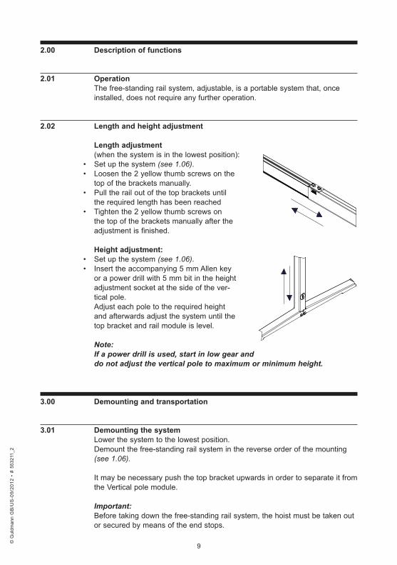
Length .adjustment (when the system is in the lowest position):
• Set up the system (see 1.06).• Loosen the 2 yellow thumb screws on the
top of the brackets manually.• Pull the rail out of the top brackets until
the required length has been reached• Tighten the 2 yellow thumb screws on
the top of the brackets manually after the adjustment is finished.
Height .adjustment:• Set up the system (see 1.06).• Insert the accompanying 5 mm Allen key
or a power drill with 5 mm bit in the height adjustment socket at the side of the ver-tical pole. Adjust each pole to the required height and afterwards adjust the system until the top bracket and rail module is level.
Note: If a power drill is used, start in low gear anddo not adjust the vertical pole to maximum or minimum height.
3 .00 . Demounting .and .transportation .
3 .01 . Demounting .the .systemLower the system to the lowest position.Demount the free-standing rail system in the reverse order of the mounting (see 1.06).
It may be necessary push the top bracket upwards in order to separate it from the Vertical pole module.
Important:Before taking down the free-standing rail system, the hoist must be taken out or secured by means of the end stops.
10
© G
uldm
ann
GB
/US
-09/
2012
• #
553
211_
2
© G
uldm
ann
GB
/US
-09/
2012
• #
553
211_
2
© G
uldm
ann
GB
/US
-09/
2012
• #
553
211_
2
© G
uldm
ann
GB
/US
-09/
2012
• #
553
211_
2
3 .02 . Transporting .the .system .As a minimum, the free-standing rail system should be taken apart so that the vertical pole modules are separated from the top brackets and rail (see 3.01).
During transportation, Guldmann recommends that system, after it has been demounted, is always transported in the Guldmann Bag carrier portable, item No. 553225.
4 .00 . Maintenance .and .storage
4 .01 . CleaningClean the free-standing system with a damp cloth using ordinary household detergents. Chemicals or an autoclave must not be used when cleaning the free-standing rail system.
4 .02 . StorageThe free-standing rail system should be stored in a room where the humidity does not exceed 70%. The system free-standing rail system must not be stored in bathrooms or the like.
4 .03 . MaintenanceCheck regularly that the system is stable.
5 .00 . Service .and .life .span
5 .01 . Life .spanThe Free-standing rail system, adjustable, has an expected life span of 15 years, on the condition of correct use and correct service inspections (see 4.04).
Spare parts drawings can be obtained from the manufacturer or supplier.
11
© G
uldm
ann
GB
/US
-09/
2012
• #
553
211_
2
© G
uldm
ann
GB
/US
-09/
2012
• #
553
211_
2
© G
uldm
ann
GB
/US
-09/
2012
• #
553
211_
2
© G
uldm
ann
GB
/US
-09/
2012
• #
553
211_
2
5 .02 . Troubleshooting
1 . . The .system .is .not .stable• Check that the feet is mounted correctly• Check the Vertical poles have been pushed securely in the Top bracket• Check that the top brackets are tightened• Check that the top brackets have been positioned correctly• Check the top brackets for defects or deformities?• Check that the Yellow thumb screws are tightened
2 . . The .vertical .height .adjustment .is .not .working .Check carefully with a 5mm Allen key that the system is not stuck in the far end position.
If the top part of the Vertical pole is not moving when turning the 5mm Allen key, stop using the system and contact the distributor or the manufacturer.
6 .00 . Technical .specifications
Free-standing .rail .systemDimensions min. (HxW) . . . . . . . . . . . . . . . . . . . . . . . . . . . . . 2020 x 2720 mm Dimensions in extended pos. max. (HxW) . . . . . . . . . . . . . . 2820 x 3890 mmMaximum lifting capacity . . . . . . . . . . . . . . . . . . . . . . . . . . . . . . . . . . . . 250 kg
Total .weight .without .hoistFree-standing rail system . . . . . . . . . . . . . . . . . . . . . . . . . . . . . . . . . . .52,0 kg Vertical pole, each . . . . . . . . . . . . . . . . . . . . . . . . . . . . . . . . . . . . . . . . .13,5 kg Top brackets and rail . . . . . . . . . . . . . . . . . . . . . . . . . . . . . . . . . . . . . . .25,0 kg
MaterialsRails and posts : . . . . . . . . . . . . . . . . . . . . . . . . . . . . . . . Anodized aluminiumFeet : . . . . . . . . . . . . . . . . . . . . . . . . . . . . . . . . . . . . . . Powder varnished steelBrackets: . . . . . . . . . . . . . . . . . . . . . . . . . . . . . . . . . . . Powder varnished steel
7 .00 . EC-Declaration .of .conformity
The products are manufactured in compliance with the Council Directive 93/42/EEC of 14 June 1993 – with amendments, as medical device class 1.
12
© G
uldm
ann
GB
/US
-09/
2012
• #
553
211_
2
© G
uldm
ann
GB
/US
-09/
2012
• #
553
211_
2
© G
uldm
ann
GB
/US
-09/
2012
• #
553
211_
2
© G
uldm
ann
GB
/US
-09/
2012
• #
553
211_
2
. USA .and .countries .outside .the .EU
A . . Users .guideBefore using the product, read the entire operation manual including warranty.
B . . . WARRANTYGuldmann warrants its equipment is free from material defects under normal use, and will perform substantially in accordance with the specifications set forth in documentation provided with the equipment.
This express warranty shall be in effect for one year from the date of original purchase and installation (the “Warranty Period”). If a valid claim is made during the Warranty Period for malfunction or equipment defect, Guldmann will repair or replace the equipment at no additional cost to you. Guldmann retains sole discretion as to whether the equipment will be repaired or replaced.
This warranty shall be null and void if the equipment is operated and main-tained in any manner inconsistent with its intended use or the instructions provided with the product. Further, in order for the warranty to remain in effect for the full Warranty Period, all service to the equipment must be provided by a Guldmann designated technician. Any parts or components repaired or replaced by a Guldmann designated technician will be guaranteed for the remainder of the Warranty Period.
The warranty does not cover any part of the equipment which has been sub-ject to damage or abuse by the user or others. The warranty does not cover any part of the equipment which has been altered or changed in any way by the user or others. Guldmann does not warrant that the lifting device functions will meet your requirements, be uninterrupted or error free.
The warranty set forth is in lieu of all other express and implied warranties, whether oral, written or implied, and the remedies set forth above are your sole and exclusive remedies. Only an authorized officer of Guldmann may make modifications to this warranty, or additional warranties binding on Guld-mann. Accordingly, additional statements such as advertising or presentati-ons, whether oral or written, do not constitute warranties by Guldmann.
Service .or .RepairContact Guldmann Repair for an authorization to return any defective item during the Warranty Period. You will be provided with a return authorization number and address for returning the item for warranty service or replace-ment. Do not return items to Guldmann under warranty without receiving a Return Authorization Number.
If mailing the item, pack it carefully in a sturdy carton to prevent damage. Include your Return Authorization Number, a brief description of the problem and your return address and phone number. Guldmann does not assume the risk of loss or damage while in transit, so it is recommended you insure the package.

13
© G
uldm
ann
GB
/US
-09/
2012
• #
553
211_
2
© G
uldm
ann
GB
/US
-09/
2012
• #
553
211_
2
© G
uldm
ann
GB
/US
-09/
2012
• #
553
211_
2
© G
uldm
ann
GB
/US
-09/
2012
• #
553
211_
2

14
© G
uldm
ann
GB
/US
-09/
2012
• #
553
211_
2
© G
uldm
ann
GB
/US
-09/
2012
• #
553
211_
2
© G
uldm
ann
GB
/US
-09/
2012
• #
553
211_
2
© G
uldm
ann
GB
/US
-09/
2012
• #
553
211_
2

15
© G
uldm
ann
GB
/US
-09/
2012
• #
553
211_
2
© G
uldm
ann
GB
/US
-09/
2012
• #
553
211_
2
© G
uldm
ann
GB
/US
-09/
2012
• #
553
211_
2
© G
uldm
ann
GB
/US
-09/
2012
• #
553
211_
2

V . .Guldmann .A/SCorporate Office:Graham Bells Vej 21-23ADK-8200 Aarhus NTlf. +45 8741 3100Fax +45 8741 [email protected]
Guldmann .Inc .14401 McCormick Drive, Unit ATampa, FL 33626Tel. 800 664 8834Tel. 813 880 0619Fax 813 880 [email protected]
© G
uldm
ann
GB
/US
-09/
2012
• #
553
211_
2


![Adjustable weldable double rail clip WDM20R Weldable adjustable rail clamp base S355J2 self coloured WDM20RB m = 0,524 [kg] Item Discription Material Type / Dimensions Norm Comments](https://img.pdfslide.us/doc/110x75/5ea77a7b0719564221428ecf/adjustable-weldable-double-rail-clip-wdm20r-weldable-adjustable-rail-clamp-base.jpg)