Embed Size (px)
Citation preview

GB704 INSTALLATION TOOL
GAGE BILT
MADE IN U.S.A.
GAGE BILT Inc. 44766 Centre Court (586) 226-1500
Clinton Twp. MI 48038 (586) 226-1505 Fax e-mail: [email protected] / www.gagebilt.com
GAGE BILT TOOLS ARE AVAILABLE WORLDWIDE E-MAIL US FOR A DISTRIBUTOR NEAR YOU.

2 6/11 Rev. 8/11
TABLE OF CONTENTS Description Page Warnings ............................................................................................................................................... 3 Principle of Operation .......................................................................................................................... 4 How to use the GB704 .......................................................................................................................... 5 Description, Operation and Maintenance ........................................................................................... 6 Filling, Bleeding and Troubleshooting................................................................................................ 7 Overhaul, Disassembly and Parts Lists ........................................................................................... 8-9 DEXRON ® III Oil Safety Data ............................................................................................................ 10 Nose Assembly Selection Chart ........................................................................................................ 11 EU Conformity and Warranty ............................................................................................................. 12
SPECIFICATIONS
Hand Held Weight - 4.30 lbs. Air pressure req'd - 90-100 p.s.i. Air consumption - 3.9 CFM at 20 Cycles a minute Hydraulic fluid - Automatic Transmission Fluid, Dexron III, or equivalent. Setting stroke - .540" Rated pull load - 3,300 lbs. Noise level - 81.5 dB (A) Vibration - Tested– No hazards found.
1.56 Ø
(39.6mm)
1.14 Ø
(29.9mm)
1.78
(45.2mm)1.25
(31.8mm)
3.88 Ø
(98.6mm)5.07
(128.8mm)
11.16
(283.4mm)
4.15
(105.4mm)
6.21
(157.7mm)
1.92
(48.8mm)
4.15
(105.4mm)

3 6/11 Rev. 8/11
WARNING
Do not pull fastener unless it is placed in an assembly, pin will eject forcibly when pintail breaks
off. Severe personal injury may result.
WARNING
Do not operate without Stat-O-Seal (S572) and cap screw (402482). Pressurized hydraulic fluid may
cause severe personal injury.
WARNING
When operating, repairing or overhauling tool, wear approved eye protection. Do not look in front of
nose assembly or rear of tool when installing fastener.
WARNING
Always disconnect tool from power before performing any maintenance to any tool or nose assembly. Ensure that all connections are proper and there are no visible leaks from tool or hoses
before connecting to power.
WARNING
Do not operate if deflector, bottle, catcher bag or vacuum tube is removed or damaged, broken
pintails may eject forcibly from rear of tool. Severe personal injury may result.
CAUTION
Ensure that nose assembly and tip are properly matched for the fastener being installed.
CAUTION
Keep Nose Assemblies clean and free of chips and debris.
WARNING
Be sure there is adequate clearance for tool and operator's hands before proceeding. Keep fingers clear of any moving parts. Keep fingers clear from
fasteners and installed materials. Severe personal injury may result.
WARNING
It is required to use hearing protection. A test was carried out in a simulated work environment where
the background level was 73.2 DBA. In this condition the max level was 81.5 DBA. Therefore, it
is required where prolonged use, hearing protection be used.
CAUTION
Do not use beyond the design intent.
WARNING
Tool must be maintained in a safe working condition at all times and examined on a regular
daily basis for damage or wear. Any repair should be done by qualified personnel trained on Gage Bilt
procedures.
SAFETY WARNINGS
WARNING
Where prolonged use is foreseen, it is recommended a tool balancer be used. Check suspension device to ensure that it is secure.
WARNING
Do no use tool in explosive atmosphere.
CAUTION
Tool is not to be used as a hammer.
WARNING
Risk of crushing exists if nose assembly is not attached.
NOTE: PLEASE READ THIS MANUAL BEFORE SERVICING OR USING THIS TOOL.
REVIEW ALL WARNINGS AND CAUTIONS TO PREVENT SEVERE PERSONAL INJURY OR DAMAGE THE TOOL.
WARNING
It is recommended tool be operated 50 out of every 60 minutes, where prolonged use is expected.
WARNING Shock:
It is recommended operator wear a suitable glove during operation where prolonged use is expected.
WARNING Air pressure not to exceed 100 psi., except where noted.

4 6/11 Rev. 8/11
AIR
PRESSURE
AIR
PRESSURE
AIR
PISTON
AIR
PRESSURE
AIR
PRESSURE
AIR
PRESSURE
PRINCIPLE OF OPERATION When the trigger is depressed, the pressurized air inside of the tool is released allowing spring pressure to move the valve spool causing the air to be redirected. The air is directed to the top of the air piston, moving it in a downward direction. The air below the air piston is then directed through the valve sleeve and exhausted out of the bottom of the tool. Simultaneously, the piston rod connected to the air piston is also moving down, forcing hydraulic oil up and into the front side of the cylinder head, causing the piston to move to the rear of the cylinder head. The internal components of the attached nose assembly are also moving with the piston to start the fastener installation. When the fastener installation is completed, the trigger is released. Air pressure is then built up inside of the handle causing the valve spool to return to its original position and reversing the sequence directing air pressure to the rear of the cylinder head, causing the piston to move to the forward position.
OIL
PRESSURE
AIR
PRESSURE
AIR
PRESSURE
EXHAUST
AIR
PISTON
VALVE
SPOOL
PISTON
ROD
CYLINDER
HEADHEAD
PISTON

5 6/11 Rev. 8/11
HOW TO USE THE GB704
WARNING: OPERATOR MUST READ AND UNDERSTAND ALL WARNINGS AND CAUTIONS.
WARNING: IT IS REQUIRED THAT EYE PROTECTION AND HEARING PROTECTION BE WORN DURING OPERATION.
WARNING: DO NOT PULL RIVET IN THE AIR. PERSONAL INJURY FROM FASTENER EJECTING MAY OCCUR.
WARNING: AIR IS EXHAUSTED FROM THE BOTTOM OF THE TOOL. DIRECT BOTTOM OF THE TOOL (EXHAUSTED AIR) AWAY FROM OPERATOR, OTHER PERSONS WORKING IN THE VICINITY, FOREIGN MATTER AND LIQUID.
CAUTION: DO NOT USE BEYOND THE DESIGN INTENT. The tool is shipped with a plastic plug in the air inlet connector. The connector has a 1/4-18 female pipe thread to accept end-user air hose fitting. The tool comes with oil and is ready to use. 1. Remove plastic shipping plug from Swivel (A-249) and screw in your air fitting. 2. Attach Deflector (200232) to rear of Cylinder Head Assembly (704108).
WARNING: ROTATE DEFLECTOR AWAY FROM OPERATOR AND OTHER PERSONS WORKING IN THE VICINITY. 3. Connect air hose with 90 psi. to tool (3/8 minimum diameter air line is mandatory, 90 p.s.i. is recommended) and
cycle tool a few times by depressing and releasing trigger. (Clean dry air is mandatory). WARNING: ENSURE AIR HOSE IS SECURELY CONNECTED TO AVOID POSSIBLE HOSE WHIPPING. 4. Disconnect air hose from tool. 5. Select proper Nose Assembly, screw collet and anvil onto the tool and attach securely. (See proper data sheet for
further instructions.)
6. Connect air supply.
7. Insert rivet into Nose Assembly and the application then depress trigger. Upon releasing the trigger the stem will eject to the rear of the tool.
DEFLECTOR
CYLINDER
HEAD
NOSE
ASSEMBLY
RIVETWORK
RED
SHIPPING
PLUG
QUICK
DISCONNECT
FITTING
TRIGGER

6 6/11 Rev. 8/11
DESCRIPTION
WARNING: THE BALANCE OF THIS TOOL IS DESIGNED FOR HORIZONTAL USE AND IS NOT SUITED FOR
ANY OTHER APPLICATIONS. GAGE BILT WILL BE PLEASED TO ADVISE FOR YOUR SPECIFIC APPLICATION.
The GB704 is a pneumatic-hydraulic tool designed specifically for the efficient installation of a wide range of blind rivets. It weighs 4.30 lbs. and can be operated in any position with one hand. It has a .540" rivet setting stroke and a rated pull load of 3300 pounds with 90 psi air pressure at the air inlet. The GB704 riveter is designed to operate on a range of air pressure, with 90 to 100 psi providing the maximum efficiency. At 90 psi air pressure, the GB704 does not exceed 81.5 db (A) and consumes 3.9 cfm at 20 cycles a minute. The air inlet is provided with 1/4-18 female pipe threads to accept the users air hose fitting. NOSE ASSEMBLIES ARE NOT FURNISHED WITH TOOL AND MUST BE ORDERED SEPARATELY. (See page 8 for nose assembly recommendations.)
MAINTENANCE
WARNING: EXCESSIVE CONTACT WITH HYDRAULIC FLUID AND LUBRICANTS SHOULD BE AVOIDED.
WARNING: MAINTENANCE PERSONNEL MUST READ AND UNDERSTAND ALL WARNINGS AND CAUTIONS.
The performance of any tool depends upon good maintenance practices. Following these minimal requirements for service and care will extend the life of your tool. *Only use an air supply set at 90-100 p.s.i. equipped with a filter-regulator to prevent wear. *The tool will eventually lose some hydraulic oil. Keep the hydraulic system full (only use Dexron III, or equivalent)
and free of air by using the air bleeder (704153) on a weekly basis. *Proper care by operator is necessary in maintaining full productivity and reducing downtime. Read all applicable tool manuals and nose assembly data sheets prior to operating tools. *Keep nose assemblies, especially jaws, clean and free of chips and debris. Lube jaws and collet surfaces that
jaws ride on with light machine oil on a daily basis. *All Screwed End Caps, Base Covers, Air Fittings, Triggers, Screws and Nose Assemblies are to be examined at
the end of each working shift to check that they are secure. *Check daily all Hoses, Couplings, and Tools for damage or air/hydraulic leaks. Tighten or replace (if necessary).
*For a complete overhaul, tool kit GB704TK is recommended (see page 8).
CLEANING AND LUBRICATING PROCEDURE Daily cleaning and lubrication of nose assembly will greatly reduce downtime and increase life of components. Using sewing machine oil, or an equivalent cleaner/lubricant, follow instructions below.
1. Disconnect tool vacuum line (if equipped). 2. Point nose assembly into oil as shown (Fig. A).
3. Cycle tool 8-10 times and wipe dry.
TORQUE SPECIFICATIONS Button Head Cap Screws (A-928) = 40 inch lbs. Flexlock Nut (400559) = 40 inch lbs. Packing Plug (704118) = 45 foot lbs. End Cap (704112) = 45 foot lbs. Button Head Cap Screws (402482) = 35-40 inch lbs. (Do NOT over-tighten)
Fig A.

7 6/11 Rev. 8/11
FILLING AND BLEEDING TOOL
WARNING: DO NOT CYCLE TOOL WITHOUT AIR BLEEDER, OR THE SCREW AND STAT-O-SEAL, INSTALLED IN TOOL HEAD. SEVERE PERSONAL INJURY MAY RESULT. CAUTION: BEFORE FILLING HANDLE, AIR PISTON SHOULD BE ALL THE WAY DOWN. CAUTION: WHEN FORCING PISTON ROD ASSEMBLY DOWNWARD WITH HEAD CYLINDER ASSEMBLY REMOVED, HYDRAULIC FLUID WILL EJECT FORCIBLY FROM HANDLE.
To replace a small amount of oil in the tool, attach the air bleeder and connect tool to air line. Cycle a number of times. Disconnect air, remove the air bleeder, and reinstall the cap screw. This will ensure the removal of any air from the hydraulic system and its replacement with fluid.
* FILLING & BLEEDING VIDEO AVAILABLE AT: www.gagebilt.com/bleeding.htm
Should it become necessary to completely refill the tool (such as would be required after tool has been dismantled and reassembled), take the following steps after depressing trigger AND DISCONNECTING THE AIR SUPPLY: 1. Remove head assembly from handle assembly. Slowly push piston completely forward. 2. Fill handle and the oil passage on top of handle with automatic transmission fluid, Dexron III or equivalent. When looking
at the top of the handle, the oil passage is the hole that is counterbored for S832 o'ring. 3. Replace head assembly with care, ensuring gasket (704129) and o'ring (S832) are properly installed. Tighten cap screws (A-928 uniformly to prevent leakage around gasket. 4. Remove screw (402482) and stat-o-seal (S572) install bleeder bottle (704153) and connect tool to air line, cycle ten to twenty times to fully circulate fluid through hydraulic system. 5. DISCONNECT AIR FROM TOOL. Remove bleeder bottle (704153) install screw (402482) and stat-o-seal (S572). Reconnect air and cycle tool 10 more times. Check tool stroke, if stroke doesn’t check .540" min. (See figures below) repeat steps 4 & 5.
TROUBLESHOOTING Providing all maintenance conditions have been met, follow this systematic approach to diagnosis. 1. MORE THAN ONE PULL IS REQUIRED TO BREAK RIVET.
a) Tool needs to be bled. (See filling and bleeding instructions.) b) Spring has fatigued, replace. c) Jaws are stripped or packed with chips. Clean or replace. d) Incorrect nose tip.
2. SLOW OR PARTIAL OPERATION WHEN THE TRIGGER IS DEPRESSED a) Head Piston Rings (A-1118) and (400789) could be worn or damaged. Replace. b) Piston Rod Rings (401102) and (S945) could be worn or damaged. Replace. c) Muffler (704146) or filter inside spool (704143) may be plugged with dirt. Clean thoroughly and back-blow with
compressed air. d) Hole in metering screw in valve spool (704143) may be blocked or damaged. Hole diameter should be .028". Clear
and size or replace. 3. NO OPERATION WHEN TRIGGER IS DEPRESSED
a) Tool seized due to mechanical failure or damaged parts. 4. OIL LEAKAGE
a) DO NOT OPERATE WITH OIL LEAKING FROM TOOL. HIGH PRESSURE OIL MAY CAUSE SEVERE PERSONAL INJURY. b) Any oil leaking externally should be traced to its source. An o'ring or seal that leaks should be replaced. 5. AIR BYPASS FROM VALVE HOUSING
a) If the spring (704141) breaks or dislodges, air will flow freely through the muffler (704146). Replace or reset. Valve spring installation tool (704162) is recommended.
b) Check o'rings on valve sleeve (704140), valve spool (704143), and valve plug (704145). If worn or damaged, replace. Valve sleeve removal tool (704163) is recommended.
6. FASTENER STEM JAMMED IN NOSE ASSEMBLY a) Nose assembly components require service. DISCONNECT AIR FROM TOOL, remove the nose from the tool and disassemble. Replace worn or broken parts. Clean the surface the jaws ride on. b) Stems lodged side by side in the follower. Disassemble, remove stems, and reassemble. c) Incorrect follower.
.740 (18.8mm)'B'
.200 (5.1mm)

8 6/11 Rev. 8/11
OVERHAUL The disassembly and re-assembly procedure can be accomplished by utilizing the following instructions and drawings. Use extreme care during disassembly and re-assembly not to damage, mar or nick any smooth surface that comes in contact with seals. Before installing seals, always apply a good lubricant, such as Lubriplate®, to the surfaces. It is recommended that tool kit (GB704TK) be used to facilitate overhaul. A complete overhaul can be achieved by the use of Service Kit 704033 which contains a complete set of o'rings, back-up rings, screws, washers and gasket. It is recommended that this service kit be kept available for spare parts.
GB704TK Service Tool Kit Includes:
704149 Piston Rod Wrench Assembly
704150 Packing Plug Wrench Assembly
704151 Power Cylinder Tool
704152 Seal Guide
S1178 Valve Extractor
704162 Valve Spring Installation Tool
704163 Valve Sleeve Removal Tool
Part No. Description
HEAD Remove nose assembly and adapter from tool before attempting disassembly of head assembly. Remove end cap (704112). Push against threaded end of head piston (704507) to slide it out of head cylinder (704108). Be careful not to damage threads or cause burrs on polished piston rod surface.
WARNING: DISPOSE OF HYDRAULIC FLUID IN ACCORDANCE WITH ALL ENVIRONMENTAL LAWS AND REGULATIONS
APPLICABLE TO YOUR AREA.
The re-assembly sequence is the opposite of disassembly. (See Filling and Bleeding instructions.) Apply Loctite® #242 and torque the button head cap screws (A-928) uniformly to 40 inch lbs. to prevent leakage around the gasket.
704101
NOSE FITTING
A-193 - O'RING
401086 - BACK-UP RING
704507 - PISTON
S829 - O'RING
200232
DEFLECTORA-193 - O'RING
A-1118 - POLYSEAL
704112 - CAP
704108
HEAD CYLINDER
ASSEMBLY
402482 - BUTTON HEAD CAP SCREW
S572
STAT-O-SEAL
400789 - O'RING
400789 - O'RING
(O'RING IN POLSYSEAL
MUST FACE IN
THIS DIRECTION)
WARNING: DEPRESS TRIGGER AND DISCONNECT FROM AIR WITH HEAD PISTON IN THE REAR POSITION BEFORE
OVERHAUL. SEVERE PERSONAL INJURY MAY OCCUR IF AIR HOSE IS NOT DISCONNECTED. USE CAUTION WHEN FORCING PISTON ROD ASSEMBLY DOWNWARD WITH HEAD CYLINDER ASSEMBLY REMOVED, HYDRAULIC FLUID WILL EJECT FORCIBLY FROM HANDLE.
704214
STEM CATCHER BAG
704149
PISTON ROD WRENCH
704151
POWER CYLINDER TOOL
704152
SEAL GUIDE
704150
PACKING PLUG WRENCH
704153
BLEEDER BOTTLE
704162
VALVE SPRING
INSTALLATION TOOL
704163
VALVE SLEEVE
REMOVAL TOOL
S1178
VALVE EXTRACTOR
(704214 CATCHER BAG SHOWN ABOVE IS SOLD SEPARATELY)

9 6/11 Rev. 8/11
HANDLE To inspect air cylinder bore, remove base cover (704125). Any further disassembly will require removal of the cylinder head (704108) first. For complete disassembly, start by removing base cover (704125). Next, holding tool upright, remove four button-head cap screws (A-928). Lift cylinder head (704108) from handle (704132) and set aside O-ring (S832) and gasket (704129). Empty all hydraulic fluid into a container. Place piston rod wrench (704149) down into top of power cylinder (751131), into the hex of piston rod assy. (704138). While holding this wrench, remove flexlock nut (400559) using a 7/16" socket wrench. Still holding piston rod wrench, remove air piston (704121) using packing plug wrench (704150), by turning counterclockwise. When air piston is completely free from piston rod, tap or push on the piston rod wrench to eject air piston from bottom of handle. After removal of air piston, slide piston rod (704138) back up to the end of its travel. Using packing plug wrench (704150) remove packing plug (704118). With packing plug removed, power cylinder (751131) can be removed by pushing on power cylinder tool (704151) when inserted into top of power cylinder. To reassemble the handle, reverse the above procedure, being certain that all o'rings are properly lubricated before installation. Torque packing plug (704118) to 45 foot lbs. Attach the seal guide (704152) to the piston rod (704138) and tap the piston rod through the packing plug (704118). Attach air piston (704121) and flexlock nut (400559) torque flexlock nut to 40 inch lbs. Attach air piston (704121) to piston rod (704138). With the piston rod in the down position, fill oil passage on top of handle with automatic transmission fluid, Dexron III or equivalent, when looking at top of handle the oil passage is the hole that has a counterbore for (S832) o'ring. Replace gasket (704129) and o'ring (S832), just prior to replacing cylinder head (704108). (See Filling & Bleeding instructions.)
AIR VALVE
WARNING: DISCONNECT TOOL FROM ITS AIR SOURCE BEFORE DISASSEMBLY.
To disassemble, disconnect tool from its air source. Remove pin (704244) and muffler (704146). Insert valve extractor (S1178) into end of valve plug (704145) and pull it out. Using the same procedure, pull out spool (704143). NOTE: It should never be necessary to remove valve sleeve (704140) unless the ports in the sleeve are plugged from contaminated air. If ports are plugged, use needle nose pliers to grasp end of spring (704141), turning clockwise and pulling to dislodge from groove in casting. NOTE: 704162 valve spring tool will facilitate the proper installation of the spring (704141), valve sleeve (704140) can be pulled out using valve sleeve removal tool 704163.
704143 - VALVE SPOOL
ASSEMBLY
400781 - O'RING
704140 - VALVE SLEEVE
704141 - SPRING
400778 - O'RING
400783 - O'RING
704145 - VALVE PLUG
400783 - O'RING
704146 - MUFFLER
704244 - PIN
S730 - QUAD RING
A-287 - O'RING
S115 - BACK-UP RING
704118 - PACKING PLUG
405757 - O'RING
S115 - BACK-UP RING
A-287 - O'RING
S731 - BACK-UP RING
S731 - BACK-UP RING
704121 - AIR PISTON
ASSEMBLY
400559 - FLEXLOCK NUT
S725 - O'RING
704125 - BASE COVER
S734 - RETAINING RING
751131 - POWER CYLINDER
403805 - O'RING
401102 - BACK-UP RING
S945 - O'RING
704138
PISTON ROD ASSEMBLY
(INCLUDES 401102 & S945)
704132 - HANDLE
704130 - TRIGGER
ASSEMBLY
704129 - GASKET
S832 - O'RING
A-249 - SWIVEL
A-928 - BUTTON
HEAD CAP SCREW (4)
10 6/11 Rev. 8/11
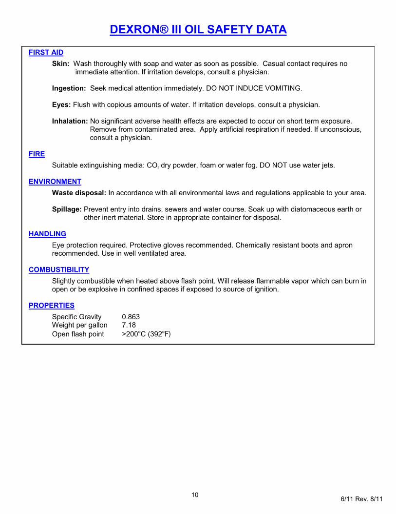
FIRST AID
Skin: Wash thoroughly with soap and water as soon as possible. Casual contact requires no immediate attention. If irritation develops, consult a physician. Ingestion: Seek medical attention immediately. DO NOT INDUCE VOMITING. Eyes: Flush with copious amounts of water. If irritation develops, consult a physician. Inhalation: No significant adverse health effects are expected to occur on short term exposure. Remove from contaminated area. Apply artificial respiration if needed. If unconscious, consult a physician. FIRE
Suitable extinguishing media: CO2 dry powder, foam or water fog. DO NOT use water jets. ENVIRONMENT
Waste disposal: In accordance with all environmental laws and regulations applicable to your area. Spillage: Prevent entry into drains, sewers and water course. Soak up with diatomaceous earth or
other inert material. Store in appropriate container for disposal.
HANDLING
Eye protection required. Protective gloves recommended. Chemically resistant boots and apron recommended. Use in well ventilated area.
COMBUSTIBILITY
Slightly combustible when heated above flash point. Will release flammable vapor which can burn in open or be explosive in confined spaces if exposed to source of ignition.
PROPERTIES
Specific Gravity 0.863 Weight per gallon 7.18
Open flash point >200°C (392°F)
DEXRON® III OIL SAFETY DATA

11 6/11 Rev. 8/11
GB704 - SELECTION CHART
FASTENER DIAMETER STRAIGHT RIGHT ANGLE (3) OFFSET
1/8 456MAX-701-17 (2) 456MAX-753A-54 (2) 456MAX-704-43OS (2)
5/32 456MAX-704-35 (2)
3/16 456MAX-749-35 (4,2)
3/32 3C-704-16 3C-704-54RA 3C-715-40OS (1)
1/8 4C-704-16 4C-704-54RA 4C-715-40OS (1)
5/32 5C-704-16 5C-704-54RA 5C-715-40OS (1)
3/16 6C-704-16 6C-704-54RA 6C-715-40OS (1)
3/32 3A-704-16 3A-704-54RA 3A-715-40OS (1)
1/8 4A-704-16 4A-704-54RA 4A-715-40OS (1)
5/32 5A-704-16 5A-704-54RA 5A-715-40OS (1)
3/16 6A-704-16 6A-704-54RA 6A-715-40OS (1)
8/32 GS8-704-16 GS8-704-54RA GS8-715-40OS (1)
CHERRYMAX® and MBC® are registered trademarks of Cherry Aerospace Fasteners.
NUT PLATE RIVETS
MS20600 SERIES
CCR244/264/274
MS/9SP/PT
BACR15CC/CF/DA/DR
GROUND STUD
M83454
BACS53B1EA1/2
'A' CODE
NAS1398A
NAS1399A
CHERRYMAX®,
CHERRYMAX® 'AB',
MBC® LOCK CREATOR
BACR15FR/FP,
BACR15GF/GK,
GAGE BILT CERTIFIES THE GB704 WILL INSTALL THE ABOVE FASTENERS
4) FRONT END EJECTING NOSE ASSEMBLY.
NOTE: THE LAST 2 DIGITS OF THE NOSE ASSEMBLY REPRESENTS THE LENGTH THE NOSE
1) 715 SERIES NOSE ASSEMBLIES REQUIRE 704001 ADAPTER.
2) INSTALLS 1/8", 5/32", AND 3/16" DIAMETERS
3) RIGHT ANGLE NOSE ASSEMBLIES MAY REQUIRE MORE THAN ONE PULL
EXTENDS FROM THE TOOL I.E. -20 = 2.0 INCHES 9/13

12 6/11 Rev. 8/11
Seller warrants that all goods covered by this catalog will conform to applicable specifications and will replace or repair, F.O.B. our plant, any goods providing defective from faulty workmanship, or material, for 6
months from date of shipment. Said warranty to remain in effect if, and only if, such goods are used in accordance with all instructions as to maintenance, operation and use, set forth in manuals and instruction sheets furnished by seller. Sellers obligation under this warranty shall be limited to the repair or rework of the goods supplied or replacement thereof, at Seller’s option, and in no case is to exceed the invoice value of said goods. Under no circumstances will the seller be liable for incidental or consequential damages or for damages incurred by the buyer or subsequent user in repairing or replacing defective goods or if the goods covered by this warranty are reworked or subjected to any type of additional processing. This warranty is void if Seller is not notified in writing of any rejections or defects within 6 months after the receipt of the material by the customer. THIS WARRANTY IS MADE IN LIEU OF ALL OTHER WARRANTIES EXPRESSED OR IMPLIED, INCLUDING MERCHANTABILITY.
WARRANTY
DECLARATION OF CONFORMITY
WE DECLARE THAT THE EQUIPMENT SPECIFIED HEREIN CONFORMS TO THE FOLLOWING STANDARDS AND DIRECTIVES.
EN12100-1 & EN12100-2
EN13849 EN792-1:2000+A1
COUNCIL DIRECTIVE: MACHINE DIRECTIVE 2006/42/EC
EQUIPMENT DESCRIPTION:
GB704 FASTENER INSTALLATION TOOL
MANUFACTURER: GAGE BILT Inc.
SIGNATURE:
NAME: BRIAN LEIGH PRODUCT MANAGER CLINTON TWP., MI U.S.A. MAY 2010 (586) 226-1500
GAGE BILT
DEXRON® IS A REGISTERED TRADEMARK OF GENERAL MOTORS CORPORATION. LUBRIPLATE® IS A REGISTERED TRADEMARK OF FISKE BROTHERS REFINING. .