Embed Size (px)
Citation preview
Gauge Face Wear Caused with Vehicle/Track Interaction
Makoto ISHIDA*, Mitsunobu TAKIKAWA, Ying JIN
Railway Technical Research Institute2-8-38 Hikari-cho, Kokubunji-shi, Tokyo 185-8540, Japan
Tel: +81-42-573-7291, Fax: +81-42-573-7360E-mail*: [email protected]
Abstract The authors are focussing on the influence of vehicle/track interaction such as attack angle ofwheelset and lateral force interacting between wheel and rail on gauge face wear of rails and flangevertical wear of wheels. So several track site dynamic measurements have been carried out for twoyears at Shinkansen sharp curved tracks to understand the actual vehicle/track lateral and verticalinteractions and to estimate the influence of gauge face wear on the vehicle/track interaction. Also,the experiments of gauge face wear have been carried out using a large twin-disc machine to studythe effect of attack angle and lateral force on the amount of wear. Then, 3-D FEM analysis ofcontact stresses has been performed to estimate the possibility of plastic deformation and weartaking place at rail gauge corner and wheel flange contact. In this study, the large variations of vehicle/track interaction with types of bogies and the greatinfluence of gauge face wear shape on the vehicle track interactions were obtained from the tracksite measurements. Also, the significant effect of attack angle on the amount of gauge face wear wasobtained in the experiments using a large twin-disc machine, which meant the increase of attackangle let the contact point between wheel and rail specimens moved toward the increase of slidingspeed. In general, sliding speed is roughly proportional to wear amount. From the FEM analysis,the possibility of very large plastic deformation and wear on the contact surface between wheel andrail was identified so that the effect of profile on reducing the amount of wear was estimated.
Keyword: Gauge face wear, Attack angle, Contact stress, 3-D FEM analysis, Sharp curve
1. Introduction Renewing worn high rails at sharp curved tracks relatively has a significant influence onmaintenance costs. Because preventive grinding has a great effect on reducing rolling contactfatigue defects called squats [1][2]. It is important to clarify some factors that progress the wear ofhigh rails, and predict and estimate the gauge face wear based on the effect of those factors [3]. It isexpected that the prediction of gauge face wear will effectively reduce the scheduled maintenancework and costs. The authors are focusing on the effect of dynamic vehicle/track interaction, such aslateral force, attack angle, and others, on the amount of wear. Then, the authors measured the vehicle/track interaction when cars ran on new rails and wornrails at sharp curved tracks of Shinkansen to understand the actual rail/wheel behaviors. Also theauthors carried out FEM contact stress analyses and laboratory experiments to study wearphenomenon. This paper describes discussions on the results and information obtained from theseanalyses and experiments.
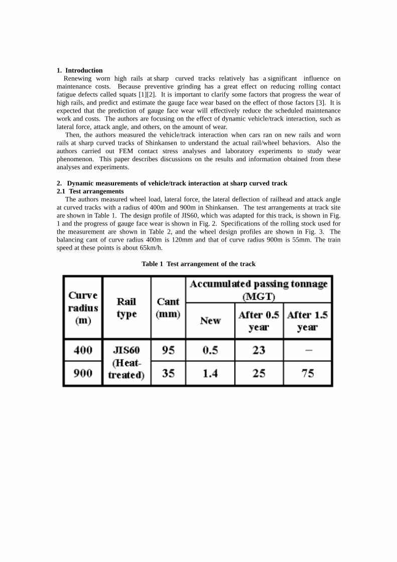
2. Dynamic measurements of vehicle/track interaction at sharp curved track2.1 Test arrangements The authors measured wheel load, lateral force, the lateral deflection of railhead and attack angleat curved tracks with a radius of 400m and 900m in Shinkansen. The test arrangements at track siteare shown in Table 1. The design profile of JIS60, which was adapted for this track, is shown in Fig.1 and the progress of gauge face wear is shown in Fig. 2. Specifications of the rolling stock used forthe measurement are shown in Table 2, and the wheel design profiles are shown in Fig. 3. Thebalancing cant of curve radius 400m is 120mm and that of curve radius 900m is 55mm. The trainspeed at these points is about 65km/h.
Table 1 Test arrangement of the track
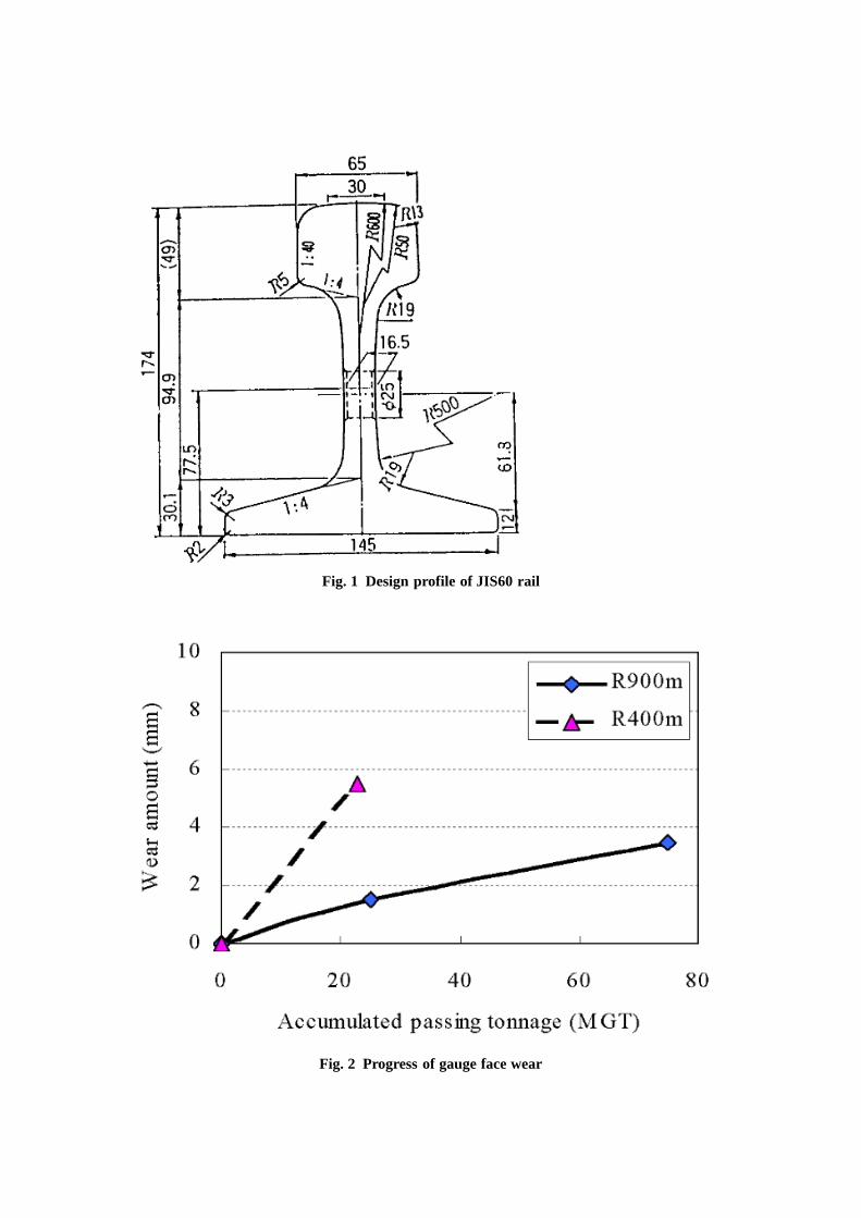
Fig. 1 Design profile of JIS60 rail
Fig. 2 Progress of gauge face wear
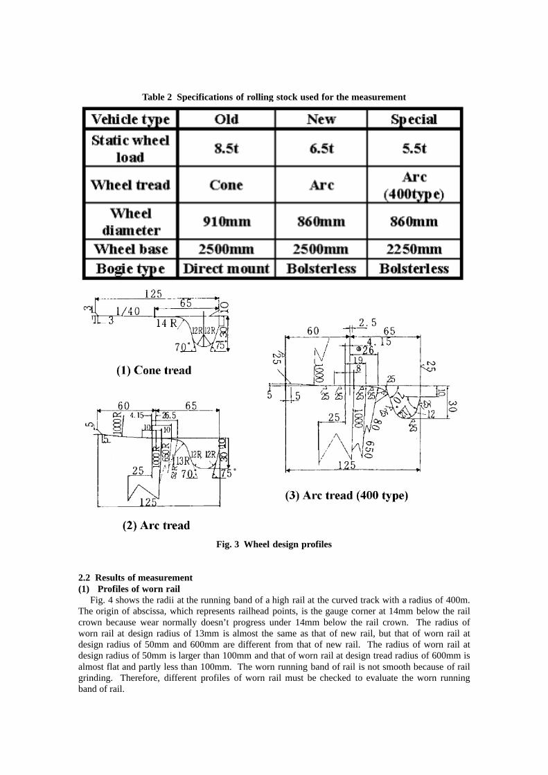
Table 2 Specifications of rolling stock used for the measurement
Fig. 3 Wheel design profiles
2.2 Results of measurement(1) Profiles of worn rail Fig. 4 shows the radii at the running band of a high rail at the curved track with a radius of 400m.The origin of abscissa, which represents railhead points, is the gauge corner at 14mm below the railcrown because wear normally doesn’t progress under 14mm below the rail crown. The radius ofworn rail at design radius of 13mm is almost the same as that of new rail, but that of worn rail atdesign radius of 50mm and 600mm are different from that of new rail. The radius of worn rail atdesign radius of 50mm is larger than 100mm and that of worn rail at design tread radius of 600mm isalmost flat and partly less than 100mm. The worn running band of rail is not smooth because of railgrinding. Therefore, different profiles of worn rail must be checked to evaluate the worn runningband of rail.
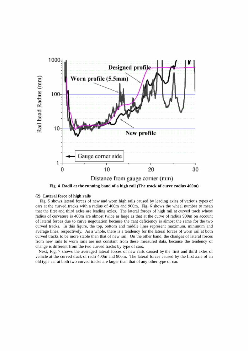
Fig. 4 Radii at the running band of a high rail (The track of curve radius 400m)
(2) Lateral force of high rails Fig. 5 shows lateral forces of new and worn high rails caused by leading axles of various types ofcars at the curved tracks with a radius of 400m and 900m. Fig. 6 shows the wheel number to meanthat the first and third axles are leading axles. The lateral forces of high rail at curved track whoseradius of curvature is 400m are almost twice as large as that at the curve of radius 900m on accountof lateral forces due to curve negotiation because the cant deficiency is almost the same for the twocurved tracks. In this figure, the top, bottom and middle lines represent maximum, minimum andaverage lines, respectively. As a whole, there is a tendency for the lateral forces of worn rail at bothcurved tracks to be more stable than that of new rail. On the other hand, the changes of lateral forcesfrom new rails to worn rails are not constant from these measured data, because the tendency ofchange is different from the two curved tracks by type of cars. Next, Fig. 7 shows the averaged lateral forces of new rails caused by the first and third axles ofvehicle at the curved track of radii 400m and 900m. The lateral forces caused by the first axle of anold type car at both two curved tracks are larger than that of any other type of car.
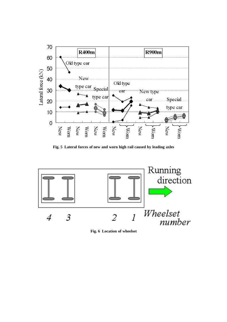
Fig. 5 Lateral forces of new and worn high rail caused by leading axles
Fig. 6 Location of wheelset
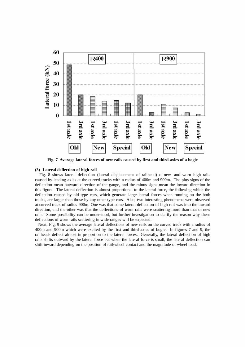
Fig. 7 Average lateral forces of new rails caused by first and third axles of a bogie
(3) Lateral deflection of high rail Fig. 8 shows lateral deflection (lateral displacement of railhead) of new and worn high railscaused by leading axles at the curved tracks with a radius of 400m and 900m. The plus signs of thedeflection mean outward direction of the gauge, and the minus signs mean the inward direction inthis figure. The lateral deflection is almost proportional to the lateral force, the following which thedeflection caused by old type cars, which generate large lateral forces when running on the bothtracks, are larger than those by any other type cars. Also, two interesting phenomena were observedat curved track of radius 900m. One was that some lateral deflection of high rail was into the inwarddirection, and the other was that the deflections of worn rails were scattering more than that of newrails. Some possibility can be understood, but further investigation to clarify the reason why thesedeflections of worn rails scattering in wide ranges will be expected. Next, Fig. 9 shows the average lateral deflections of new rails on the curved track with a radius of400m and 900m which were excited by the first and third axles of bogie. In figures 7 and 9, therailheads deflect almost in proportion to the lateral forces. Generally, the lateral deflection of highrails shifts outward by the lateral force but when the lateral force is small, the lateral deflection canshift inward depending on the position of rail/wheel contact and the magnitude of wheel load.
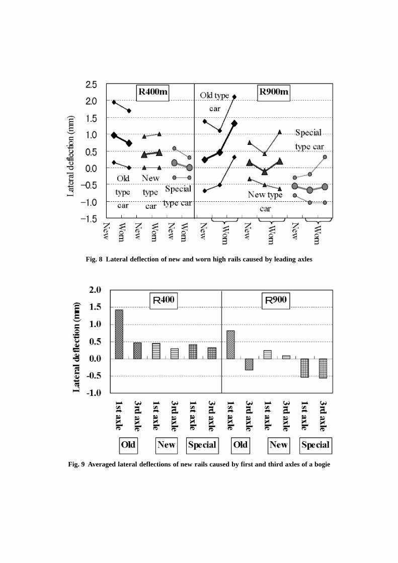
Fig. 8 Lateral deflection of new and worn high rails caused by leading axles
Fig. 9 Averaged lateral deflections of new rails caused by first and third axles of a bogie
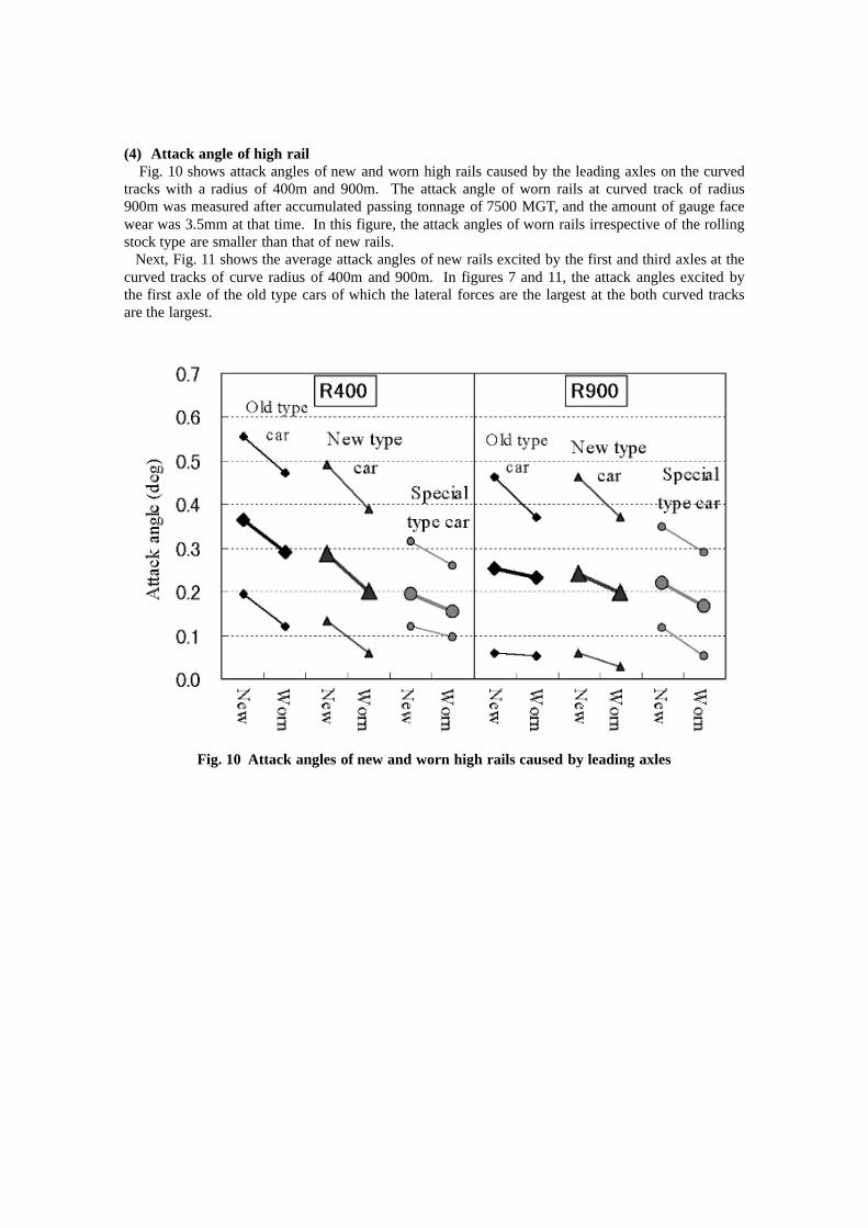
(4) Attack angle of high rail Fig. 10 shows attack angles of new and worn high rails caused by the leading axles on the curvedtracks with a radius of 400m and 900m. The attack angle of worn rails at curved track of radius900m was measured after accumulated passing tonnage of 7500 MGT, and the amount of gauge facewear was 3.5mm at that time. In this figure, the attack angles of worn rails irrespective of the rollingstock type are smaller than that of new rails. Next, Fig. 11 shows the average attack angles of new rails excited by the first and third axles at thecurved tracks of curve radius of 400m and 900m. In figures 7 and 11, the attack angles excited bythe first axle of the old type cars of which the lateral forces are the largest at the both curved tracksare the largest.
Fig. 10 Attack angles of new and worn high rails caused by leading axles
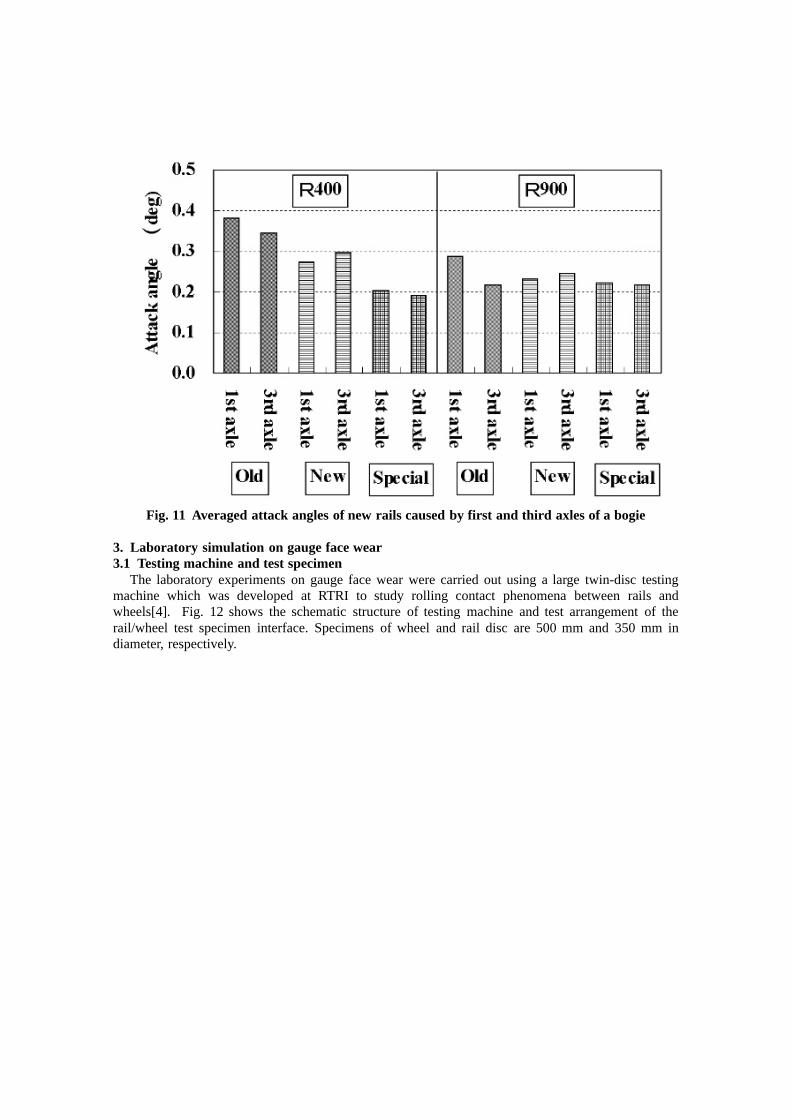
Fig. 11 Averaged attack angles of new rails caused by first and third axles of a bogie
3. Laboratory simulation on gauge face wear3.1 Testing machine and test specimen The laboratory experiments on gauge face wear were carried out using a large twin-disc testingmachine which was developed at RTRI to study rolling contact phenomena between rails andwheels[4]. Fig. 12 shows the schematic structure of testing machine and test arrangement of therail/wheel test specimen interface. Specimens of wheel and rail disc are 500 mm and 350 mm indiameter, respectively.
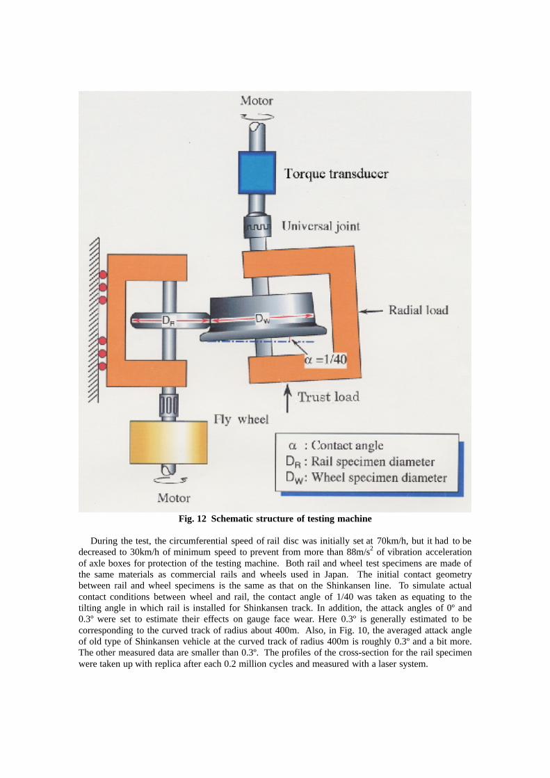
Fig. 12 Schematic structure of testing machine
During the test, the circumferential speed of rail disc was initially set at 70km/h, but it had to bedecreased to 30km/h of minimum speed to prevent from more than 88m/s2 of vibration accelerationof axle boxes for protection of the testing machine. Both rail and wheel test specimens are made ofthe same materials as commercial rails and wheels used in Japan. The initial contact geometrybetween rail and wheel specimens is the same as that on the Shinkansen line. To simulate actualcontact conditions between wheel and rail, the contact angle of 1/40 was taken as equating to thetilting angle in which rail is installed for Shinkansen track. In addition, the attack angles of 0º and0.3º were set to estimate their effects on gauge face wear. Here 0.3º is generally estimated to becorresponding to the curved track of radius about 400m. Also, in Fig. 10, the averaged attack angleof old type of Shinkansen vehicle at the curved track of radius 400m is roughly 0.3º and a bit more.The other measured data are smaller than 0.3º. The profiles of the cross-section for the rail specimenwere taken up with replica after each 0.2 million cycles and measured with a laser system.
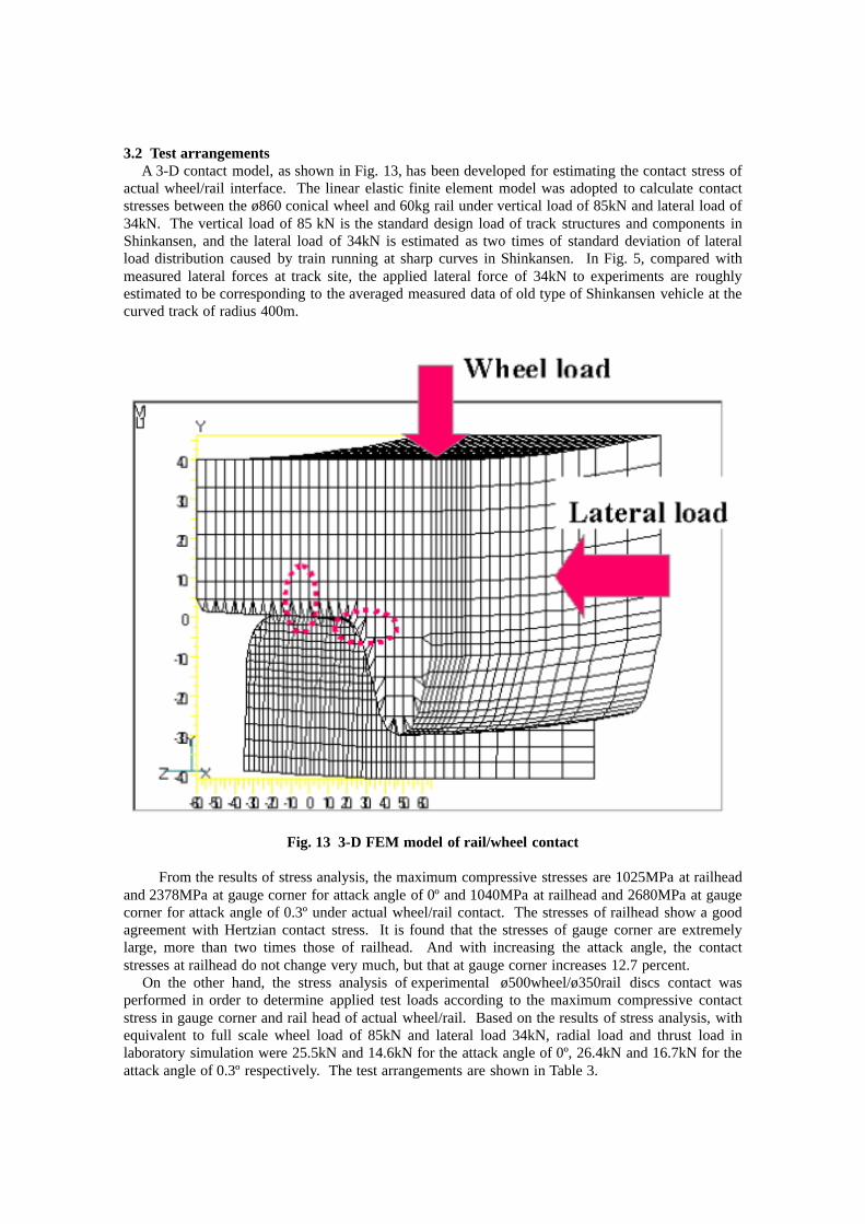
3.2 Test arrangements A 3-D contact model, as shown in Fig. 13, has been developed for estimating the contact stress ofactual wheel/rail interface. The linear elastic finite element model was adopted to calculate contactstresses between the ø860 conical wheel and 60kg rail under vertical load of 85kN and lateral load of34kN. The vertical load of 85 kN is the standard design load of track structures and components inShinkansen, and the lateral load of 34kN is estimated as two times of standard deviation of lateralload distribution caused by train running at sharp curves in Shinkansen. In Fig. 5, compared withmeasured lateral forces at track site, the applied lateral force of 34kN to experiments are roughlyestimated to be corresponding to the averaged measured data of old type of Shinkansen vehicle at thecurved track of radius 400m.
Fig. 13 3-D FEM model of rail/wheel contact
From the results of stress analysis, the maximum compressive stresses are 1025MPa at railheadand 2378MPa at gauge corner for attack angle of 0º and 1040MPa at railhead and 2680MPa at gaugecorner for attack angle of 0.3º under actual wheel/rail contact. The stresses of railhead show a goodagreement with Hertzian contact stress. It is found that the stresses of gauge corner are extremelylarge, more than two times those of railhead. And with increasing the attack angle, the contactstresses at railhead do not change very much, but that at gauge corner increases 12.7 percent. On the other hand, the stress analysis of experimental ø500wheel/ø350rail discs contact wasperformed in order to determine applied test loads according to the maximum compressive contactstress in gauge corner and rail head of actual wheel/rail. Based on the results of stress analysis, withequivalent to full scale wheel load of 85kN and lateral load 34kN, radial load and thrust load inlaboratory simulation were 25.5kN and 14.6kN for the attack angle of 0º, 26.4kN and 16.7kN for theattack angle of 0.3º respectively. The test arrangements are shown in Table 3.
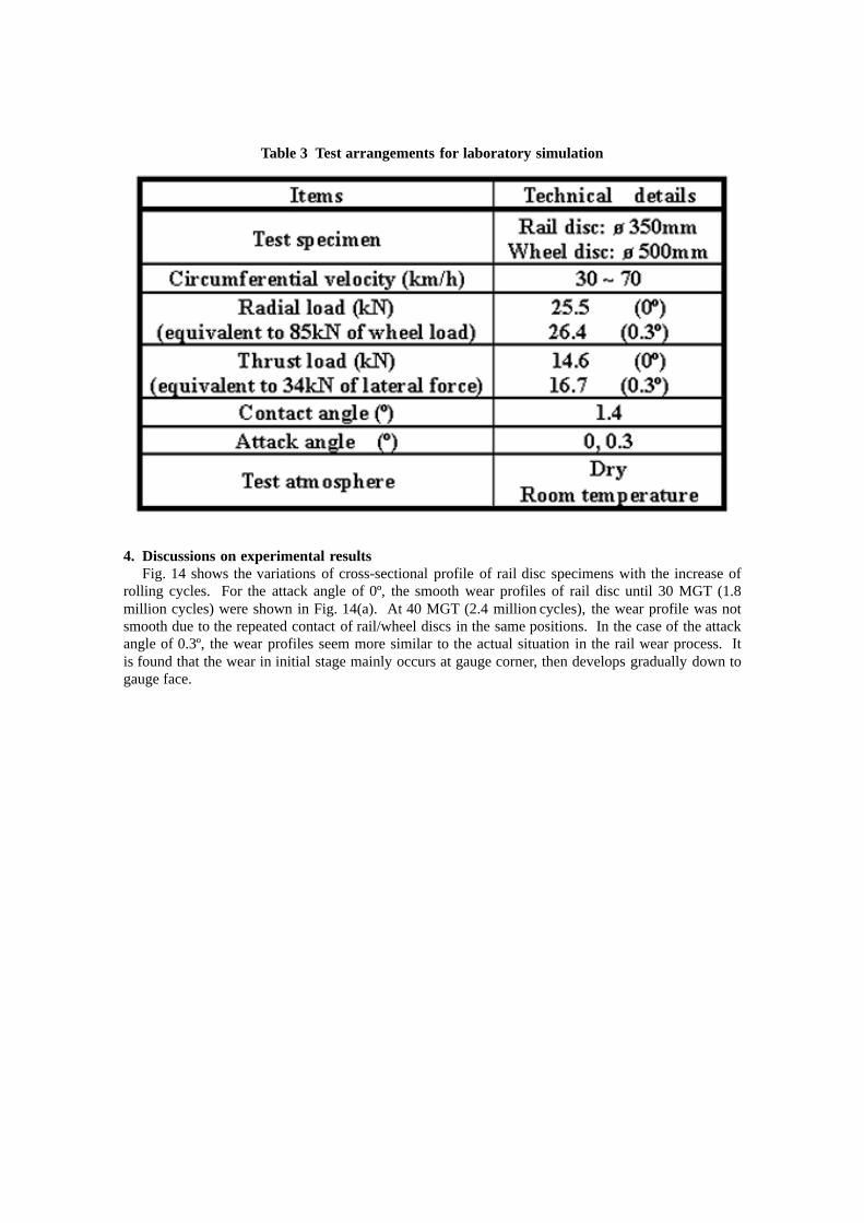
Table 3 Test arrangements for laboratory simulation
4. Discussions on experimental results Fig. 14 shows the variations of cross-sectional profile of rail disc specimens with the increase ofrolling cycles. For the attack angle of 0º, the smooth wear profiles of rail disc until 30 MGT (1.8million cycles) were shown in Fig. 14(a). At 40 MGT (2.4 million cycles), the wear profile was notsmooth due to the repeated contact of rail/wheel discs in the same positions. In the case of the attackangle of 0.3º, the wear profiles seem more similar to the actual situation in the rail wear process. Itis found that the wear in initial stage mainly occurs at gauge corner, then develops gradually down togauge face.
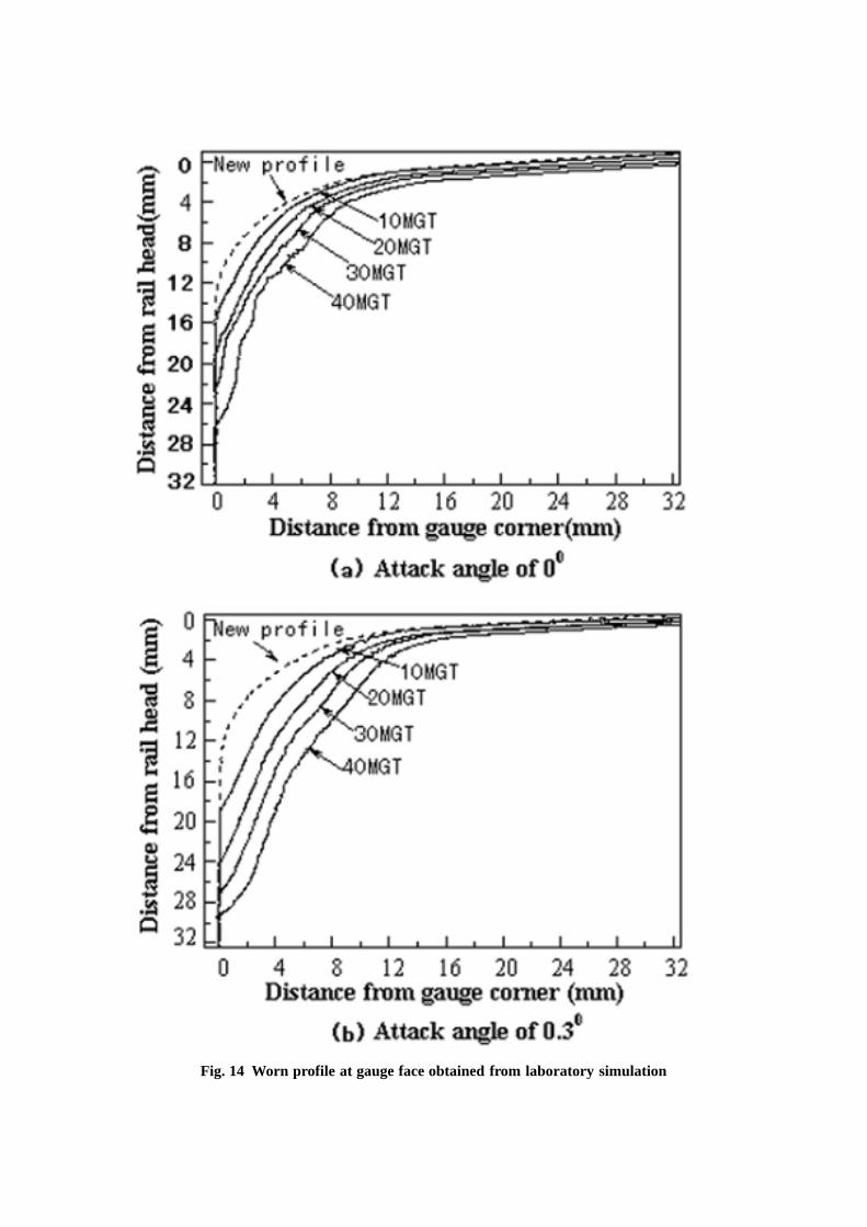
Fig. 14 Worn profile at gauge face obtained from laboratory simulation
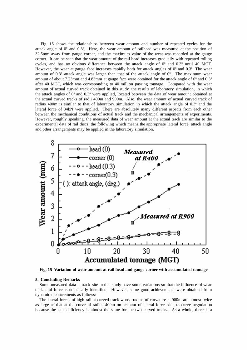
Fig. 15 shows the relationships between wear amount and number of repeated cycles for theattack angle of 0º and 0.3º. Here, the wear amount of railhead was measured at the position of32.5mm away from gauge corner, and the maximum value of the wear was recorded at the gaugecorner. It can be seen that the wear amount of the rail head increases gradually with repeated rollingcycles, and has no obvious difference between the attack angle of 0º and 0.3º until 40 MGT.However, the wear at gauge face increases rapidly both for attack angles of 0º and 0.3º. The wearamount of 0.3º attack angle was larger than that of the attack angle of 0º. The maximum wearamount of about 7.23mm and 4.83mm at gauge face were obtained for the attack angle of 0º and 0.3ºafter 40 MGT, which was corresponding to 40 million passing tonnage. Compared with the wearamount of actual curved track obtained in this study, the results of laboratory simulation, in whichthe attack angles of 0º and 0.3º were applied, located between the data of wear amount obtained atthe actual curved tracks of radii 400m and 900m. Also, the wear amount of actual curved track ofradius 400m is similar to that of laboratory simulation in which the attack angle of 0.3º and thelateral force of 34kN were applied. There are absolutely many different aspects from each otherbetween the mechanical conditions of actual track and the mechanical arrangements of experiments.However, roughly speaking, the measured data of wear amount at the actual track are similar to theexperimental data of rail discs, the following which means the appropriate lateral force, attack angleand other arrangements may be applied in the laboratory simulation.
Fig. 15 Variation of wear amount at rail head and gauge corner with accumulated tonnage
5. Concluding Remarks Some measured data at track site in this study have some variations so that the influence of wearon lateral force is not clearly identified. However, some good achievements were obtained fromdynamic measurements as follows: The lateral forces of high rail at curved track whose radius of curvature is 900m are almost twiceas large as that at the curve of radius 400m on account of lateral forces due to curve negotiationbecause the cant deficiency is almost the same for the two curved tracks. As a whole, there is a
tendency for the lateral forces of worn rail at both curved tracks to be more stable than that of newrail. The lateral deflection is almost proportional to the lateral force, the following which thedeflection caused by old type cars, which generate large lateral forces when running on the bothtracks, are larger than those by any other type cars. Generally, the lateral deflection of high railsshifts outward by the lateral force but when the lateral force is small, the lateral deflection can shiftinward depending on the position of rail/wheel contact and the magnitude of wheel load. The attackangle of worn rails irrespective of the vehicle types is smaller than that of new rails. The attackangles excited by the first axle of the old type cars of which the lateral forces are the largest at theboth curved tracks are the largest. Roughly speaking, the measured data of wear amount at actual tracks are similar to theexperimental data of rail discs, the following which means the appropriate lateral force, attack angleand other arrangements may be applied in the laboratory simulation. In this study, the influence of vehicle/track interaction on gauge face wear was investigated androughly understood. Then, the possibility of prediction of gauge face wear based on vehicle/trackinteraction can be identified form the achievements of this study. Further study will be expected.
6. Acknowledgements The authors thank East Japan Railways for their co-operation with the dynamic measurements at atrack site and field investigation.
Reference
[1] Grassie, S. L. and Kalousek, J., Rolling Contact Fatigue of Rails: Characteristics, Causes and
Treatments, in Proc. 6th. Int. Heavy Haul Conference, Cape Town, (1997)381-404[2] Ishida, M. and Abe, N., Experimental Study on the Effect of Preventive Grinding for Shinkansen
Rail, Proc. 6th. Int. Heavy Haul Conference, Cape Town, (1997)565-575[3] Clayton, P., Predicting the wear of rails on the curves from laboratory data, Wear, 181-183
(1995) 11-19.[4] Ishida, M. and Abe, N., Experimental Study on Rolling Contact Fatigue from the Aspect of
Residual Stress, Wear, 191 (1996) 65-71.

![Hokuriku Shinkansen(via Nagano)Timetable …[Tōkyō→Kanazawa] Hokuriku Shinkansen(via Nagano)Timetable From January 6th, 2020 to February 29th Tsurugi701 Tsurugi703 Hakutaka591](https://img.pdfslide.us/doc/110x75/5e6fa285aaf29f59f73bda16/hokuriku-shinkansenivia-naganoitimetable-tkyakanazawa-hokuriku-shinkansenivia.jpg)


![Hokuriku Shinkansen(for Kanazawa) Timetable[Tōkyō→Kanazawa] Hokuriku Shinkansen(for Kanazawa) Timetable After October 25, 2019 Tsurugi701 Tsurugi703 Hakutaka591 Tsurugi705](https://img.pdfslide.us/doc/110x75/5e6f9f755ee5d125e548c0d1/hokuriku-shinkansenifor-kanazawai-timetable-tkyakanazawa-hokuriku-shinkansenifor.jpg)


![New Hokuriku Shinkansen(for Kanazawa)Timetable · 2019. 11. 15. · [Tōkyō→Kanazawa] Hokuriku Shinkansen(for Kanazawa)Timetable After November 30,2019 Tsurugi701 Tsurugi703](https://img.pdfslide.us/doc/110x75/6076841772461b2ffa67b2c7/new-hokuriku-shinkansenifor-kanazawaitimetable-2019-11-15-tkyakanazawa.jpg)
![Hokuriku Shinkansen(for Kanazawa)Timetable[Tōkyō→Kanazawa] Hokuriku Shinkansen(for Kanazawa)Timetable From November 30th, 2019 to January 5th, 2020 Asama605 Kagayaki507](https://img.pdfslide.us/doc/110x75/5e6f9f755ee5d125e548c0cf/hokuriku-shinkansenifor-kanazawaitimetable-tkyakanazawa-hokuriku-shinkansenifor.jpg)